secure data center for enterprise— threat management with nextgen ips
TRANSCRIPT

Secure Data Center for Enterprise— Threat Management with NextGen IPSDesign Guide—Last Updated: August 26, 2014

About the Authors
Tom Hogue
Mike Storm
Bart McGlothin
2
Matt Kaneko
About the Authors
Tom Hogue, Security Solutions Manager, Security Business Group, Cisco
Tom is the Data Center Security Solutions Manager at Cisco with over 20 years in
developing integrated solutions with Cisco and previous roles in the industry. Tom led
the development of the industry leading data center solutions such as the FlexPods,
Vblocks, and Secure Multi-tenancy. In his current role, he leads the solution
development for the Secure Data Center for the Enterprise Solution portfolio and
co-authored the Single Site Clustering with TrustSec Cisco Validated Design Guide.
Mike Storm, Sr. Technical Engineering Leader, Security Business Group, Cisco CCIE Security #13847
Mike leads the global security community at Cisco Systems for competitive
architectures and insight. One of his primary disciplines is Security in the Data Center;
and develops architectures focused on tightly integrating Next-Generation Security
Services with Data Center and Virtualization technologies for enterprise organizations.
Storm has over 20 years in the networking and cyber security industry as an
Enterprise Consultant and Technical Writer, as well as a Professional Speaker on such
topics. Storm is the author of several relevant papers, including the Secure Data
Center Design Field Guide and co-author of the Single Site Clustering with TrustSec
Cisco Validated Design Guide.
Bart McGlothin, Security Systems Architect, Security Business Group, Cisco
Bart is a Security Solutions Architect at Cisco with over 15 years of industry solutions
experience. Bart leads Cisco's involvement with the National Retail Federation's
Association for Retail Technology Standards Committee. Prior to Cisco, Bart worked
as the Network Architect at Safeway, Inc.
Matt Kaneko, Security Systems Architect, Security Business Group, Cisco
Matt Kaneko is the solution technical lead for Secure Data Center Solution team. In this role, Matt and his team work closely with product marketing teams of various business groups along with customer’s feedback to create solution architecture. Prior to this role, Matt has worked as a Technical Marketing Manager for various Cisco Security Product lines which includes Cisco ASA Next Generation Firewall, Cisco Intrusion Protection System, Cisco AnyConnect and associated Management products line.

C O N T E N T S
Introduction 5Goal of this Document 5Intended Audience 6
Secure Data Center for the Enterprise Solution Overview 6Executive Summary 6
Solution Design Overview 7Threat Management with NextGen IPS 7
Cyber Threats Affecting the DC 8Attack Chain 10Indicators of Compromise 11The Evolving and Expanding Threat Landscape 12A Security Model that Leverages Integrated Threat Defenses 13
Threat Management System Capabilities 15Threat Containment and Remediation 16Access Control and Segmentation 16Identity Management 17Application Visibility 17Logging and Traceability Management 17Strategic Imperatives to Implement Integrated Threat Defenses 18
Threat Management Enabling Technologies 19Retrospective Security—Beyond the Event Horizon 19Key Technology for Retrospection—Trajectory 20Network File and Device Trajectory 21
Threat Management Capabilities Along Entire Path 29Validated Components 30
Threat Management with NextGen IPS Design Considerations 31FirePOWER Appliance and Management Platform Integration 31
Platform Management—FireSIGHT Management Center 31Using Redundant FireSIGHT Management Centers 32License Considerations 33NextGen IPS Fabric Integration 35Threat Management with NextGen IPS Design 36
Threat Management System Capabilities—Design Considerations 54Threat Containment and Remediation 55
3Secure Data Center for the Enterprise—Threat Management with NextGen IPS

Access Control and Segmentation 60Identity Management 62Application Visibility and Control 63Logging and Traceability Management 66
Validation Results 68
Summary 68
References 69
4Secure Data Center for the Enterprise—Threat Management with NextGen IPS

Introduction
Goal of this DocumentThe Cisco Secure Data Center for the Enterprise is a portfolio of solutions that provides design and implementation guidance for enterprises that want to deploy physical and virtualized workloads in their data centers while providing the best protection available to address today’s advanced data security threats. This document is specifically focused on providing design guidance for adding Threat Management with NextGen IPS into the Secure Data Center for the Enterprise Solution Portfolio. This document builds on top of the design and deployment guidance provided in the associated solutions, as illustrated in the solution map shown in Figure 1.
Figure 1 Cisco Secure Data Center for the Enterprise Solution Portfolio
For additional content that lies outside the scope of this document, see the additional content on the Secure Data Center Solution Portal at the following URL: http://www.cisco.com/c/en/us/solutions/enterprise/design-zone-secure-data-center-portfolio/index.html
3479
30
Cisco Secure EnclaveArchitecture
Single-Site Clusteringwith Cisco TrustSec
Cisco Threat Managementwith NextGen IPS
Cisco Cyber Threat Defensefor the Data Center
Converged Infrastructure• Compute• Storage• Hyperviso (Flexpod, Vblock, VSPEX)
VirtualizationInfrastructure Mgmt. Access LayerSecure Enclaves
Firewall ClusteringIntrusion PreventionReal-time UpdatesManagement
TrustSec• SXP• Secure Group Tags• Policy Enforcement• SGACLs • FWACLs
NextGen IPS in ASA Cluster Defense CenterFireSightApplication Visibility
Network AMPFireAMPRetrospectionFile TrajectoryNetwork Trajectory
Lancope StealthWatch• FlowCollector• FlowSensor
NetFlowNSEL
CISCO SECURE DATA CENTER FOR THE ENTERPRISE SOLUTION PORTFOLIO
Corporate Headquarters:
Copyright © 2014 Cisco Systems, Inc. All rights reserved
Cisco Systems, Inc., 170 West Tasman Drive, San Jose, CA 95134-1706 USA

Secure Data Center for the Enterprise Solution Overview
Intended AudienceThis document is intended for, but not limited to, security architects, system architects, network design engineers, system engineers, field consultants, advanced services specialists, and customers who want to understand how to deploy a robust security architecture in a data center to address today’s advanced threats; with the continued flexibility to operate virtualized and physical workloads; and function in traditional modes or have migrated towards cloud operational models. This document also leverages additional complementary solutions that are documented in separate design and deployment guides. This design guide assumes that the reader is familiar with the basic concepts of IP protocols, quality of service (QoS), high availability (HA), and security technologies. This guide also assumes that the reader is aware of general system requirements and has knowledge of enterprise network and data center architectures.
Secure Data Center for the Enterprise Solution Overview
Executive SummaryThe Secure Data Center for the Enterprise Portfolio evolved from a single design guide that provided customers guidance on implementing the Cisco ASA Firewalls into the data center fabric. In November of 2013, the single design guide was updated with a modular approach to creating a comprehensive set of design guides for customers. The Single Site Clustering with TrustSec solution introduced ASA 5585-X clustering for scalability, TrustSec for policy aggregation, and Intrusion Prevention for threat protection. When this solution is combined with the Secure Enclaves Reference Architecture and the Cyber Threat Defense for Data Center, the combination becomes a very powerful security solution portfolio for our customers; and as such, the collection is referred to as the Secure Data Center for the Enterprise Portfolio, with the intention to grow the solution portfolio for future capabilities.
The Threat Management with NextGen IPS is the next Cisco Validated Design to be added to the Secure Data Center for the Enterprise Solution Portfolio. This new Cisco Validated Design builds on top of Single Site Clustering with TrustSec by showing customers how to integrate the FirePOWER NextGen IPS into the architecture, and how the solution provides a comprehensive set of capabilities for a threat management system. The design guide takes a different approach by providing a perspective from a cyber attacker’s point of view by looking at their “Attack Chain” where they develop their capabilities to execute a successful attack. By taking this approach, it becomes clear that “Cyber Defenders” need to develop new capabilities and then implement those capabilities to create a threat management system. This Cisco Validated Design does not go into the “foundational” steps to securing the data center, such as making sure that default passwords are not used, so organizations are strongly encouraged to select their industry compliance of choice and implement the security controls as appropriate. This document discusses a new set of capabilities and describes how to integrate the new FirePOWER NextGen IPS platform into the fabric.
6

Solution Design Overview
Solution Design Overview
Threat Management with NextGen IPSFigure 2 shows the architectural framework for the Threat Management with NextGen IPS solution. As a reminder, this solution builds on top of the Secure Data Center Single Site Clustering with TrustSec as a foundation, and should be treated as a pre-requisite for this design guide.
Figure 2 The Threat Management with NextGen IPS
The Threat Management with NextGen IPS leverages the design guidance of the Single Site Clustering with TrustSec that used technologies that enable deeper security capabilities throughout the data center, provided the following design guidance:
VPCPeer
VPCPeer
QFPQFP
WAN
FireSIGHTMgmntCenter
NetFlowCollector
NetFlowGenerationAppliance
IdentityServicesEngine
Tier1
Tier2
TierN
DefenseCenter
StealthWatchConsole
Cisco SecurityManager
ISE AdminPortal
UCS Director
Role basedoperations
Advanced MalwareProtection
User and Flow ContextReal Time Threat
Management ApplicationVisibility
URL Control
Managementand Operations
NetFlow BasedThreat Defense
Behavior AnalysisUser and Flow
Context AnalysisIncident Response
ManagementNetwork Forensics
Access Control PolicyManagement
User OnboardingDevice Posturing
Policy AggregationManagement
Workload and SecurityServices Automation
Converged IntegratedInfrastructureManagement
3479
31
ASA 5585-X Cluster with SourcefireNGIPS up to 16 ASA 5585-X Nodes
up to (16) Sourcefire 8250 or 8350 Stacks
(2) 10GE links
Cisco SIOAdvanced Real-Time
Threat Defense
DC Core Layer
DC Aggregationand Service Layer
North-South ProtectionsServices for server farmsNetwork Malware Protection
Note: CCL = Cluster Data LinkRedundant Links to theNexus 7000s
Virtual Network and Access
East-West Protections Zone-based filtering
PhysicalAccess
PhysicalAccess
Compute
Storage
ConvergedNetwork Stack
Rack Server Deployment
Physical-Virtual-Mixed Workload Environments
CCLCCL
7

Solution Design Overview
• ASA firewall clustering for scalability
• Fabric integration with virtual port channels (vPCs)
• Link aggregation for simplified operations
• Intrusion protection and application visibility
• Real-time signature updates
• Secure Group Tags (SGTs) for policy aggregation
The Threat Management with NextGen IPS design guide extends the Single Site Clustering with TrustSec solution by providing guidance on how to integrate the FirePOWER NextGen IPS platform into the architecture from both a physical and virtual perspective. The FirePOWER appliance provides for threat protection capabilities that are far beyond what a traditional IPS offers. When these capabilities are combined with the capabilities that were included across the Secure Data Center for the Enterprise Portfolio, the result is a comprehensive solution to offer customers a highly effective response to today’s cyber threats using highly capable threat management workflows.
Cyber Threats Affecting the DC
A typical data center for any organization is the location where the most critical and valuable assets of an organization can be found. This data can be in the form of proprietary information, customers’ contacts, customer credit cards, company financials, company banking accounts, employees information, and so on. If the data in the data center is valuable to the organization, it is also valuable to cyber criminals, whether for financial gain, espionage, or other unknown motivations. There is little doubt that the data centers are a critical asset to protect, and most organizations have in place some level of segmentation with access control policies to ensure that only authorized users are able to access information in the data center on a “need to know” basis. Unfortunately, this approach is based on some outdated assumptions, which requires a re-thinking of data centers are being secured. Many organizations have relied solely on access control lists and enforcement as the only method of protecting the data center. A primary assumption is that the “authorized” user is really who they say they are, or that the authorized user is in control of their device that is accessing the data center. One of the easiest ways for a cyber attacker to get a foothold into an enterprise organization’s network is by installing a rootkit onto a user’s end device. This can easily be accomplished when the unsuspecting user browses a malicious website when they are at home and not connected to the corporate network. (See Figure 3.)
Figure 3 Exploit Kits
Once the malware is dropped on the end user device and the user returns back to work, the malware can
3479
32
Malware server dropsmalware on client
Webserver redirects clientto malware server
CompromisedWeb server
User
Client iscompromised
8

Solution Design Overview
assume the identity of the end user, and has access to all the data center assets that the user would normally be able to access. At this point, those security access control lists will allow the malware to traverse the network into the data center (see Figure 4). This approach does not even take into account when credentials are stolen and the cyber attackers are able to gain access to data center assets with simple authorization.
Figure 4 Compromised Server
Virtual Machine Based Rootkits
When the cyber attacker has direct access to the data center, they begin to attempt to compromise the servers and applications in the data center. A relatively newer set of exploits that are directly targeting the data centers are virtual machine-based rootkits (VMBR), as shown in Figure 5. Successful VMBR exploits such as Blue Pill, Vitriol, and SubVirt have been demonstrated at Black Hat by researchers. Whether or not the exploits are in use by the cyber attacker community, the threat is real.
Figure 5 VMBR Rootkit
The fundamental question needs to be answered, “Is access control enforcement secure enough to protect the data center assets?” While there is no doubt that the cyber attacks are targeting the data center, it is the combination of legacy security models and the new cyber threats that represent a new real threat to data centers.
While the above examples are rather simplistic, the threats affecting the data center are highly complex. The next section discusses the attack chain, a new security model, and how to map the new model into sub-functions in the sections that follow.
3479
33CompromisedClient
Malware GainsKernel Access
VM
VM
VM
VM
VM
VM
3479
34Malware hasKernel Access
VirtualMachineMonitor
Compromised
Malware ContactsHome Server
VMs underCyber Attacker
ControlVM
VM
VM
VM
VM
VM
9

Solution Design Overview
Attack Chain
The previous section briefly introduced how a rootkit works, but to continue challenging previous assumptions on how to secure the data center, a deeper look at the challenges being addressed is needed. It is critically important to recognize that the more successful cyber attacks are highly targeted. The more sophisticated cyber attacks can be divided into phases using the Attack Chain model from the cyber attacker’s perspective (see Figure 6).
Figure 6 Attack Chain
John A. Tirpak’s article “Find, Track, Target, Engage, Assess” posted in July 2000 in Air Force Magazine, proposes that the concept of a kill chain originated in the speech in October of 1996 where Gen. Ronald R. Fogleman, the Air Force Chief of Staff, declared, “it will be possible to find, fix, or track anything that moves on the surface of the earth.” The concepts in the speech eventual evolved into the kill chain of “Find, Fix, Target, Engage, Assess.” Over time, several branches of the military have modified the kill chain to fit their use cases. This paper proposes yet another modified version of the kill chain concept in a way that maps closer to a software developer (or hacker) mindset. Note that the attack chain is not mapped to a specific timeline, because some cyber attackers work their targets for well over a year to avoid detection. In other cases, the attacks can come swiftly in a matter of minutes. Many organizations have used the kill chain concept in creating cyber threat defense models.
Survey
In preparation for any attack, it is important to understand what the environment looks like:
• What ports are open, and will the rootkit need to work over multiple ports?
• What operating systems are identifiable?
• What kind of counter measures and evasion techniques will the cyber attacker need to deploy.
• What are the primary defenses that the target organization has put into place?
• How far will using default passwords get the cyber attacker?
• Can a set of users email addresses be identified to send out a phishing campaign?
Unfortunately phishing campaigns are still highly successful, as reported in the Verizon 2014 Data Breech Report, where it was shown that there is still a 90 percent chance of success with just ten emails sent to end users.
Develop
After as successful survey phase of the cyber attack is complete, the cyber attacker begins by developing the capabilities for a successful attack. It is important to note that the word develop does not necessarily mean to write new malware from scratch. There are plenty of malware options for a cyber attacker to choose from without ever having to write code. Although it is well known, it is still hard to believe that one can license malware and purchase a support contract. If the attacker wants to create customized malware for their target, there is plenty of open source code that can be modified. This
3479
35Survey TestDevelop Execute Accomplish
10

Solution Design Overview
creates an incredibly efficient process for the cyber attacker community.
Test
With the proper tools in hand, the cyber attacker moves on to the test and validate stage. It is very important for the cyber attacker to be able to gain access to the target assets without detection. If they are detected too early in the attack chain, they must start all over again because the target will deploy new counter measures. Attackers need to validate that their evasion techniques are effective. Their objective is to gain access, remain undetected, and take their time to accomplish their goal.
Execute
Once the validation is complete, they are ready to establish a foothold on the target’s assets. This can be by dropping malware onto the end user devices; or gaining access to web application servers, email servers, and any other device that allows them to move laterally in the network. Once they have the foothold, they then seek to establish a secondary access method in case their primary target has deployed counter measures. This is an important step to remember, as is discussed later in this document.
Accomplish
Now that the cyber attacker has access to the target network, it is time to complete the mission by extracting valuable data, destroying data, planting evidence, and any other action that achieves their goal for the cyber attack. The cyber attacker also finds places to hide their malware for future cyber attacks.
Indicators of Compromise
In many cases, the time between the execute and accomplish phases can be over a year. Many cyber attackers use a “lie and wait” technique to maximize their return on investment in their attack. These “lie in wait” techniques generate very few if any indicators of compromise. When you consider that this approach produces so few indications of compromise when compared to the thousands of alerts generated by legacy threat systems, it is no wonder that these kinds of attacks are incredibly difficult to detect. Before the indicators of compromise were identified, the industry relied on indicators of an attack. Traditional intrusion prevention systems provided indications of attack by triggering alerts based on the matching of a signature based on a point-in-time disposition. The IPS systems were unfortunately subject to large numbers of false positives based on traffic flows that match signatures but were benign traffic. Operators then identified signatures that matched the benign traffic from particular hosts so that those traffic flows would not generate alerts. The remaining alerts were treated as indicators of attacks as identified by the IPS system, and unfortunately these false alerts were so large in number that real alerts were often drowned out and easily overlooked. When the organization had identified a credible indication of compromise, they then had to do tedious and incredibly difficult analysis to answer the following questions:
• What was the method and point of entry?
• What systems were affected?
• What did the threat do?
• Can I stop the threat and root causes?
• How do we recover from it?
• How do we prevent it from happening again?
Cyber security teams needed a new approach based on a broad set of accurate data to produce reliable
11

Solution Design Overview
indicators of compromise. Elements of such an approach that would make up a broader, yet more exact analysis of what was being seen, could include the following:
• What is this attack? Such as a known type or category.
• What are the attack specifics? Such as how it is/was executed? What may have changed on the target endpoint, and so on?
• Where did the attack come from?
• How was hostility determined?
• What is the target endpoint? Its OS?
• Is the target vulnerable to this threat?
• Has this endpoint been compromised by this or other attacks now or in the past?
• What other machines has this device contacted?
• What is the targeted application (for example, Client or Web)?
• Does the target have a chance to be impacted by this event?
• Is this a new issue or was it delivered via an outside source, such as bring-your-own-device (BYOD)?
• Is the attacking host currently in the network or outside the network?
• What was/is the root cause?
• Can the system identify immediately how many hosts or network devices may be vulnerable to this threat?
• If this attack is blocked, how can the system determine whether it is a false-positive or true-positive?
An example of a strong indicator of compromise would be if a Java application started installing and executing applications, which should never happen. Unfortunately, Java is a common threat vector and it remains a favorite for many cyber attackers. This type of attack can easily comply with any access control lists as well as be overlooked by a traditional IPS because the file signature does not trigger an alert. To achieve an advanced indication of compromise capability, events must be correlated from the following:
• Malware activities
• Intrusion detections
• Network connections
• Network file trajectories
• Device trajectories
• Device network flows; including but not limited to lateral movements, parent-child relationship, or context
The goal would be for all of the above to be correlated with network, endpoint, application, and user context. The resultant data set provides the unique ability to provide indications of compromise throughout the entire network that are accurate enough to be confidently and immediately actionable.
The Evolving and Expanding Threat Landscape
Modern extended networks and their components constantly evolve and spawn new attack vectors including: mobile devices, web-enabled and mobile applications, hypervisors, social media, web browsers, embedded computers, as well as a proliferation of devices only beginning to be imagined, brought on by the Internet of Everything.
12

Solution Design Overview
People are inside and outside the network, on any device, accessing any application, and in many different clouds. This is the any-to-any challenge, and while these dynamics have enhanced communications, they have also increased the points and ways in which hackers are getting in. Unfortunately, the way most organizations approach security has not evolved in lock-step. The majority of organizations secure extended networks using disparate technologies that do not, and cannot, work together. They also may rely too much on service providers for security in the cloud and hosting companies to protect Internet infrastructure. In this new reality, security administrators all too often have little visibility or control over the devices and applications accessing the corporate network, and limited ability to keep pace with new threats
Faced with the combination of advanced attacks and any-to-any infrastructure, security professionals are asking themselves three big questions:
1. With new business models and attack vectors, how do we maintain security and compliance as our IT landscape continues to change?
Organizations transitioning to the cloud, virtualization, or mobile devices for the productivity, agility, and efficiency these technologies provide must align their security infrastructure accordingly.
2. In an evolving threat landscape, how do we improve our ability to continuously protect against new attack vectors and increasingly sophisticated threats?
Attackers do not discriminate; they will seize on any weak link in the chain. They relentlessly drive their attacks home, frequently using tools that have been developed specifically to circumvent the target’s chosen security infrastructure. They go to great lengths to remain undetected, using technologies and methods that result in nearly imperceptible indicators of compromise.
3. How are we going to address the first two questions and reduce complexity and fragmentation of security solutions at the same time?
Organizations cannot afford to leave gaps in protection that today’s sophisticated attackers exploit. At the same time, adding complexity with disparate security solutions that are not integrated will not deliver the level of protection required against advanced threats.
A Security Model that Leverages Integrated Threat Defenses
As discussed above, new tools and technologies are needed to develop a comprehensive response to today’s threats affecting not only the data center, but also the entire enterprise. This must be done using a model that minimizes complexity and helps protect the business assets in a continuous fashion, while addressing the changes in business models, such as any-to-any. The security system should be integrated directly into the network fabric to maximize its efficiency and capability, while minimizing the risk normally associated with adding the disparate, non-network-aware security controls. To design such a system, a new model is needed to ensure that this integration can properly take place, especially in the data center, where the margin of error is so small. This new model is a useful reference when developing a comprehensive security solution for any type of network. The new model showcases a key component known as the attack continuum, which identifies each of the critical mechanisms and processes that are integral to the complete security system. (See Figure 7.)
13

Solution Design Overview
Figure 7 Integrating Threat Defenses using the Attack Continuum
This model addresses the threat problem by looking at the actions you must take before, during, and after an attack, as well as across the broad range of attack vectors such as endpoints, mobile devices, data center assets, virtual machines, and even in the cloud. Where most security solutions tend to address the threat in a point in time, it is important to look at it as a continuous cycle.
Before an Attack
Context-aware attackers require context-aware security. Organizations are fighting against attackers that have more information about the infrastructure defenders are trying to protect than defenders often have themselves. To defend before an attack occurs, organizations need total visibility of their environment—including, but not limited to, physical and virtual hosts, operating systems, applications, services, protocols, users, content, and network behavior—to achieve information superiority over attackers. Defenders need to understand the risks to their infrastructure, based on target value, legitimacy of an attack, and history. If defenders do not understand what they are trying to protect, they will be unprepared to configure security technologies for defense. Visibility needs to span the entirety of the network, endpoints, email and web gateways, virtual environments, and mobile devices, as well as to the data center. In addition, from this visibility actionable alerts must be generated so that defenders can make informed decisions.
During an Attack
Relentless attacks and blended threats do not occur in a single point of time; they are an ongoing activity and demand continuous security. Traditional security technologies can evaluate an attack only at a point in time, based on a single data point of the attack itself. This approach is no match against advanced attacks.
Instead, what is needed is a security infrastructure based on the concept of awareness; one that can aggregate and correlate data from across the extended network with historical patterns and global attack intelligence to provide context and discriminate between active attacks, exfiltration, and reconnaissance versus simply background activity. This evolves security from an exercise at a point in time to one of continual analysis and decision-making. If a file that was thought to be safe passes through but later demonstrates malicious behavior, organizations can take action. With this real-time insight security, professionals can employ intelligent automation to enforce security policies without manual intervention.
3479
36
The New Security Model
Attack Continuum
Mobile CloudVirtualEndpointNetwork
Point-In-Time Continuous
BeforeDiscoverEnforceHarden
DuringDetectBlock
Defend
AfterScope
ContainRemediate
14

Solution Design Overview
After an Attack
To address the full attack continuum, organizations need retrospective security. Retrospective security is a big data challenge, and a capability that few are able to deliver. With an infrastructure that can continuously gather and analyze data to create security intelligence, security teams can, through automation, identify indicators of compromise, detect malware that is sophisticated enough to alter its behavior to avoid detection, and then remediate.
Compromises that would have gone undetected for weeks or months can be rapidly identified, scoped, contained, and remediated. This threat-centric model of security lets organizations address the full attack continuum across all attack vectors, and to respond at any time, all the time, and in real time.
Threat Management System CapabilitiesThe attack continuum model provides a view of how address threats, and helps build a framework of capabilities so that you can start implementing security controls. For example, NIST Special Publication 800-53, “Security and Privacy Controls for Federal Information Systems and Organizations” states that “organizations can consider defining a set of security capabilities as a precursor to the security control selection process.”
The NIST publication also defines the concept of security capability as a “construct that recognizes that the protection of information being processed, stored, or transmitted by information systems, seldom derives from a single safeguard or counter measure (i.e., security control)”. Every organization should strive to achieve compliance with their relevant industry standards. While demonstrating a particular compliance to a standard is out of scope of this document, the concept of capabilities is the core of a Threat Management System and of this document. Table 1 maps the Threat Management System capabilities and descriptions to the attack continuum phases and associated products. Some products span multiple capabilities, so it is not always a 1:1 mapping.
Table 1 Threat Management System Capabilities
Threat Management System Capabilities Description Before During After ProductsThreat containment and remediation
File, packet, and flow-based inspection and analysis for threats
Endpoint protection agents, network-based flow protection
Cloud-based endpoint analysis, network-based file analysis, network-based flow analysis, signature-based analysis, sandbox analysis
Connections and flows analysis and remediation
Sourcefire FireSIGHT, intrusion protection, network-based AMP, email AMP, CWS AMP, FireAMP for end user and mobile
Access control and segmentation
Access control policies, segmentation, secure separation
Endpoint group assignments, security zones, user to asset access policies
Fabric enforcement, firewall policy enforcements, traffic normalization and protocol compliance
Policy enforcement and logging
ASA 5585-X, SGTs, SGACLs, SXP, and TrustSec capable switching fabric or ACI fabric with ASAv
15

Solution Design Overview
Threat Containment and Remediation
You need the ability to identify cyber threats and to remediate those threats in the shortest amount of time possible. This is not a point-in-time function, but a continuous function that uses retrospection so that if a piece of malware is not initially identified, the system can still locate that malware at a later point in time and remediate the compromise.
Access Control and Segmentation
Access control policies and enforcement have been the foundation for network security, and will continue to be a key foundational element. Segmentation has also been a critical element to separating traffic, but organizations have not fully use this technique to its fullest capability. These two capabilities are typically considered as separate capabilities and are broken out into separate controls in most, if not all, compliance standards. They are combined here because they are interrelated when designing and deploying the network. Every network that has deployed a proper segmentation strategy should also be deploying relevant access control policies to define their security domains. Large security domains tend to expose organizations to significant risk in the event of a data breech. New segmentation techniques are available to reduce the size of those security domains and make them easier to manage.
Identity Management
User identity and access posturing, network-based user context
User mapping to groups, resources, and acceptable access locations
User context analysis
User access and threat origination analysis and remediation
Active Directory, Cisco ISE, Sourcefire FireSIGHT
Application visibility and control
File control and trajectory, network file trajectory, application quarantine, data loss prevention
Policies to limit and control access to internal and external applications
Enforcement of application control policies, sensitive data inspection
Visibility into all applications being accessed and running on network
Sourcefire Access Control, Sourcefire NGFW
Logging and traceability management
Threat forensics and compliance
Proper configuration of threat management system reporting
Active out of band logging
Immediate access by proper threat function management platform. Consolidation of logs into central repository for further forensics and compliance
FireSIGHT Management Center for short term logs, Lancope StealthWatch for longer term NetFlow analysis logs, SIEM for log management compliance (SIEM is out of scope for project)
Table 1 Threat Management System Capabilities (continued)
Threat Management System Capabilities Description Before During After Products
16

Solution Design Overview
Identity Management
Every organization has some form of identity management and authorization capability such as Active Directory for user authentication. Unfortunately, not all organizations have deployed the capability to get a posture assessment against the user during authentication, and to map the user into the appropriate security policy based the user’s end device or location or other relevant criteria. It is also a critical capability to attach user context to traffic flows, file analysis, network connections, and any other network activity for a robust threat management capability.
Application Visibility
Application visibility across the network is a critical capability for every organization to have in their arsenal against the cyber threats. Applications are still a primary attack vector, so it is critical to be able to analyze their anomalous behaviors as they access data center assets and their communication flows.
Logging and Traceability Management
Having the ability to capture detailed logs of all aspects of network and end point activity continues to remain a critical capability. Traceability is more than just having time stamps on alerts; it is also about being able to determine a file trajectory as the malware traverses the network. The organization needs to have the ability to be able to perform an in-depth forensics investigation if a breach is discovered.
Mapping Capabilities to NIST Controls
Although compliance control mapping is out of scope of this document, a brief discussion is appropriate for completeness. A brief look at the NIST SP 800-53 Publication and the SANs Top 20 Critical Security Controls provides a mapping of the capabilities discussed above to the controls in these two publications. As shown in Table 2, not all of the controls map, but most of the Cyber Security controls are addressed.
Table 2 Threat Capability Mapping to Controls
Threat Containment
Access Control and Segmentation
Identity Management
Application Management
Logging and Traceability
Capability File, packet, and flow-based inspection and analysis for threats
Access control and segmentation
User identity and access and posturing, network-based user context
Application visibility and control
Threat forensics and compliance
17
Solution Design Overview
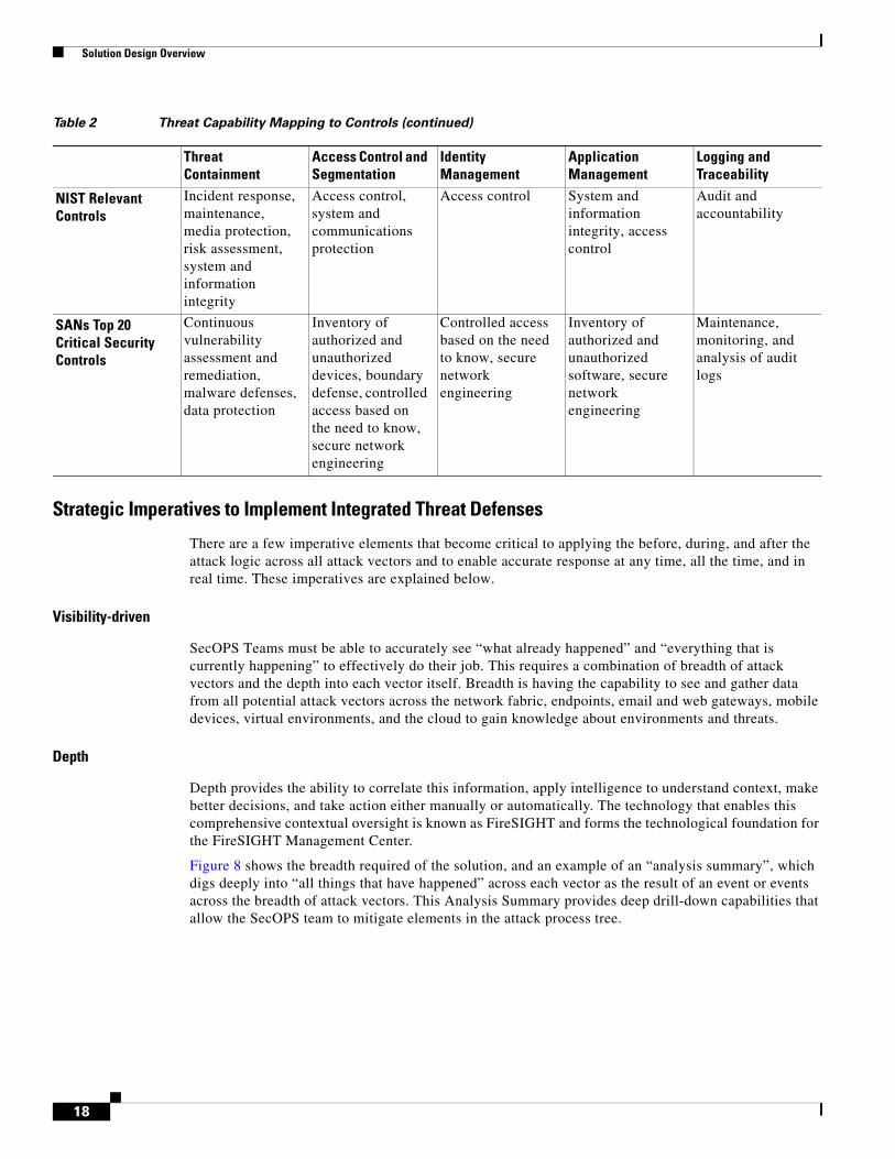
Strategic Imperatives to Implement Integrated Threat Defenses
There are a few imperative elements that become critical to applying the before, during, and after the attack logic across all attack vectors and to enable accurate response at any time, all the time, and in real time. These imperatives are explained below.
Visibility-driven
SecOPS Teams must be able to accurately see “what already happened” and “everything that is currently happening” to effectively do their job. This requires a combination of breadth of attack vectors and the depth into each vector itself. Breadth is having the capability to see and gather data from all potential attack vectors across the network fabric, endpoints, email and web gateways, mobile devices, virtual environments, and the cloud to gain knowledge about environments and threats.
Depth
Depth provides the ability to correlate this information, apply intelligence to understand context, make better decisions, and take action either manually or automatically. The technology that enables this comprehensive contextual oversight is known as FireSIGHT and forms the technological foundation for the FireSIGHT Management Center.
Figure 8 shows the breadth required of the solution, and an example of an “analysis summary”, which digs deeply into “all things that have happened” across each vector as the result of an event or events across the breadth of attack vectors. This Analysis Summary provides deep drill-down capabilities that allow the SecOPS team to mitigate elements in the attack process tree.
NIST Relevant Controls
Incident response, maintenance, media protection, risk assessment, system and information integrity
Access control, system and communications protection
Access control System and information integrity, access control
Audit and accountability
SANs Top 20 Critical Security Controls
Continuous vulnerability assessment and remediation, malware defenses, data protection
Inventory of authorized and unauthorized devices, boundary defense, controlled access based on the need to know, secure network engineering
Controlled access based on the need to know, secure network engineering
Inventory of authorized and unauthorized software, secure network engineering
Maintenance, monitoring, and analysis of audit logs
Table 2 Threat Capability Mapping to Controls (continued)
Threat Containment
Access Control and Segmentation
Identity Management
Application Management
Logging and Traceability
18

Solution Design Overview
Figure 8 Demonstrating an Example of Breadth and Depth—Everything that Happened
Threat-focused
Today’s networks extend to wherever employees are, wherever data is, and from wherever data can be accessed. Despite best efforts, keeping pace with constantly evolving attack vectors is a challenge for everyone involved and an obvious opportunity for attackers. Attackers make their living exploiting gaps that exist in the system. Policies and controls are essential to reduce the surface area of attack, but some threats will inevitably still get through. As a result, technologies also must focus on detecting, understanding, and stopping threats. Being threat-focused means thinking like an attacker, applying visibility and context to understand and adapt to changes in the environment, and then evolving protections to take action and stop threats. With advanced malware and zero-day attacks, this is an on-going process that requires continuous analysis and real-time security intelligence, delivered from local intelligence and the cloud and shared across all products for improved efficacy.
Threat Management Enabling Technologies
Retrospective Security—Beyond the Event Horizon
Retrospective security is unique to the Cisco security solution and is fundamental in combating advanced threats and modern malware. Retrospective security uses a continuous capability that consumes big data analytics to aggregate data and events across the extended network for constant tracking and analysis, to alert on and remediate items such as files, initially deemed safe that are now known to be malicious. If a file that initially passes through the detection system(s) and is thought to be good or unknown, but is later identified as malicious, the file can be retrospectively identified, the scope of the outbreak understood and contained, and ultimately the clock can be turned back to automatically remediate malware. Before to this construct was introduced and successfully implemented, there had been no way to track an attack beyond the event horizon—for example, the “point of no return” for tracking files—the moment when the file enters into the network with a “Good” disposition and immediately conceals and embeds itself for further actions.
Figure 9 shows an example of retrospection beyond the event horizon and compares point-in-time detection to the retrospective continuous analysis using a few common anti-malware techniques such as AV, IPS, and sandboxing that are considered key parts of a threat management system. Especially with modern threats being potentially “sandbox-aware”, this functionality becomes even more critical. The
19

Solution Design Overview
top portion of Figure 9 demonstrates the inadequacies of typical point-in-time detection without retrospection, while the lower portion adds continuous analysis to the point-in-time “initial disposition” to show why retrospection is required to catch modern malware and defend against advanced attacks. The lower portion also showcases why visibility of the target is so key to understanding how the threat management system can provide an accurate ‘scope’ of the potential outbreak, beyond the event horizon, and can accurately apply measures to dynamically prevent further outbreaks.
Figure 9 Event Horizon—Comparing Point-in-time Detection with Continuous Analysis
Key Technology for Retrospection—Trajectory
Trajectory is a Cisco unique technology that prevents the security solution from losing sight of malware beyond the event horizon, making it a critical component of the event or threat-centric security model that should be leveraged in the modern data center. In addition to the added visibility that Trajectory brings, Trajectory also inherently allows the SecOPS team to determine the scope of an outbreak, when it occurs, and to be able to track malware or suspicious files across the network and at the system or endpoint level. Trajectory is a function that is extended across the entire Advanced Malware Protection solution portfolio.
Trajectory is analogous to having a network flight recorder for malware, recording everything it does and everywhere it goes. Today’s malware is dynamic and can enter a network or endpoint through a variety of attack vectors and, once executed on an intended target, typically performs a number of malicious and/or seemingly benign activities, including downloading additional malware. By leveraging the power of big data analytics, the solution captures and creates a visual map of these file activities, providing visibility of all network, endpoint, and system level activity, enabling security personnel to quickly locate malware point-of-entry, propagation, and behavior. This provides
3479
37
Point-In-TimeDetection
Antivirus
Sandboxing
Initial Disposition = Clean Actual Disposition = Bad = Too Late!!
Analysis Stops
Blind to scope ofcompromise
Turns back time
Visibility andControl are Key
Sleep TechniquesUnknown ProtocolsEncryptionPolymorphism
Not 100%
Retrospective(Continuous)Detection
Initial Disposition = Clean Actual Disposition = Bad = Blocked
Analysis Continues
20

Solution Design Overview
unprecedented visibility into malware attack activity, ultimately bridging the gap from detection to remediation to control of a malware outbreak. This is a key enabler of retrospective security, which only Cisco can do.
Network File and Device Trajectory
Security personnel struggle to understand the broader impact, context, and spread of malware across the network and endpoints. Knowing whether or not the malware detection was an isolated incident or whether multiple systems were affected is critical information to have. File Trajectory delivers the ability to track malware across the network using existing FirePOWER appliances or FireAMP connectors; providing detailed information on point of entry, propagation, protocols used, and which users or endpoints are involved (see Figure 10 and Figure 11.)
Network File Trajectory looks across the entire organization and answers:
• What systems were infected?
• Who was infected first (“patient 0”) and when did it happen?
• What was the entry point?
• When did it happen?
• What else did it bring in?
Figure 10 File Trajectory across the Network
21

Solution Design Overview
Figure 11 Dynamic File Analysis Summary
The file-based capability provided by File Trajectory and Device Trajectory further enhances Cisco’s ability to provide a deeper level of data capture and visualization of malware and file activity at the system level. This delivers critical analysis capabilities for security and incident response teams to conduct root cause analysis and trace the exact relationship between malware on compromised systems and broader infections that may exist. Device Trajectory allows the system to break the reinfection lifecycle with fast root cause analysis.
Device Trajectory traces the exact relationship between malware on compromised systems and broader infections through robust search and filtering capabilities that look for suspicious activity across all systems, and even deeper analysis on systems that have FireAMP installed. It lets customers quickly find suspicious and malicious activity on one system and then very quickly search across all systems for similar indicators. Device Trajectory tracks activity and data such as the parent and child lineage and relationship: which files or applications were created by which files and which files downloaded other files, or vice-versa. Device Trajectory also looks at originating processes such as the process that spawned or executed another process. Additionally, it tracks communications, including IP addresses, ports, protocols, and URLs. (See Figure 12.)
In addition, having the dynamic trajectory information provides the ability to quickly identify potential indicators of compromise, which are changes and other behaviors indicating that compromise has happened and a breach has most likely occurred. Device Trajectory looks deeply into each device and helps to answer:
• How did the threat get onto the system?
• How bad is my infection on a given device?
• What communications were made?
• What do I not know?
• What is the chain of events?
22

Solution Design Overview
Figure 12 File and Device Trajectory
Similar to the attack chain described above, the FireSIGHT Management Center has a natural flow to how you would walk through the screens to address an intrusion or an indication of compromise. The flow diagram in Figure 13 highlights a sample flow that an operator would follow in the analysis of potential threats. The following section gives some screen capture examples in each step of the way to get to the root cause analysis step.
Note This is just a sample workflow; the example flow discussed in this section does not demonstrate the full power and capability of the FirePOWER Management System.
Figure 13 Cyber Defender Analysis Workflow Sample
From the Context Explorer screen, the operators can drill down from here for further analysis. (See Figure 14.)
ContextExplorer
Indicators ofCompromise
IntrusionInformation
FileInformation
HostProfiles
MalwareEvent
Attributes
RootCause
Analysis
ContextExplorer
Indicators ofCompromise
IntrusionInformation
FileInformation
HostProfiles
MalwareEvent
Attributes
RootCause
Analysis
3479
38
23
Solution Design Overview
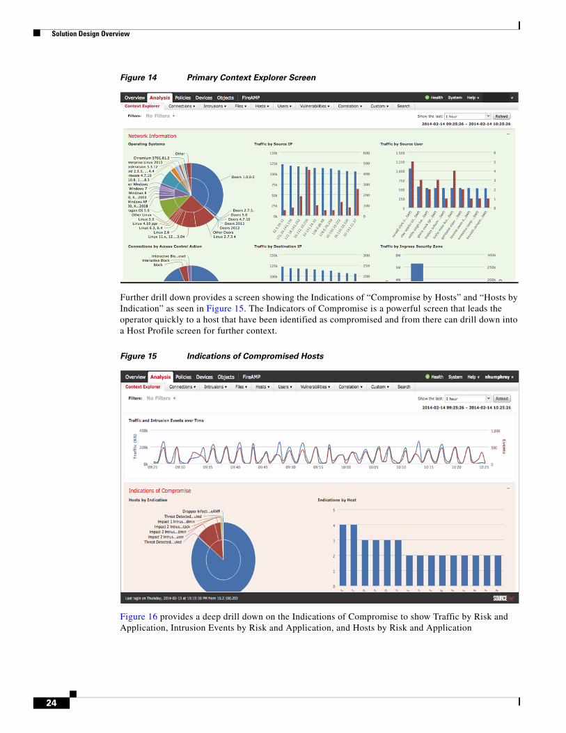
Figure 14 Primary Context Explorer Screen
Further drill down provides a screen showing the Indications of “Compromise by Hosts” and “Hosts by Indication” as seen in Figure 15. The Indicators of Compromise is a powerful screen that leads the operator quickly to a host that have been identified as compromised and from there can drill down into a Host Profile screen for further context.
Figure 15 Indications of Compromised Hosts
Figure 16 provides a deep drill down on the Indications of Compromise to show Traffic by Risk and Application, Intrusion Events by Risk and Application, and Hosts by Risk and Application
24

Solution Design Overview
Figure 16 Indications of Compromise by Client Application
Figure 17 provides a detailed Intrusion Information screen that provides Intrusion by Impact and Priority information so that the operator can focus activities on the most critical issues first. Also note that a drilldown is available to view each of the malware that has been identified.
Figure 17 Detailed Intrusion Information
25

Solution Design Overview
Further drill down into the intrusion brings to the Verified Threats Default Workflow (see Figure 18) and the Intrusion Event Specifics (see Figure 19) screens.
Figure 18 Verified Threats
Further drill down leads to the Malware Event Attributes step with the Event Specifics screen in Figure 19.
Figure 19 Event Specifics
Having completed a deep dive on the intrusion specifics, further understanding of the targeted files would be the next step in the workflow.
The File Information screen (see Figure 20) begins to map the malware to the corrupted files that have either been seen by the Network AMP or the FireAMP clients. Now the operation can see the file names, hosts, and malware mappings. It is important to note the network perspective in this view, because it is likely that more than one host will be involved in the malware detection.
26

Solution Design Overview
Figure 20 Malware and File Details
As seen in the sections above, the Network File Trajectory capability provides a network wide view on the devices and files that have been compromised. Figure 21 shows the Network File Trajectory screen with and additional drill down in to the Host Profile screen that maps the Indication of Compromise to the host.
Figure 21 Network Trajectory and Host Profile
27

Solution Design Overview
Selecting the Malware Detected IoC allows detailed attributes about of this host’s malware detections to be seen and acted upon, as seen in Figure 22. This screen provides contextual information around a malware event in such a way that an operator can assess the risk the suspected file(s) pose to the organization, even before an operator may choose to send the file to the Cisco-Sourcefire cloud for sandboxing of the file(s). Security Intelligence feeds leverage the Cisco-Sourcefire cloud, VRT, and other big data sources to enable policies to be configured based on traffic source and destination. This screen also leverages the URL reputation as provided by the Cisco-Sourcefire cloud. By leveraging multiple sources of threat events, the operator can have a full context of the threats.
Figure 22 Context-based Verified Threats
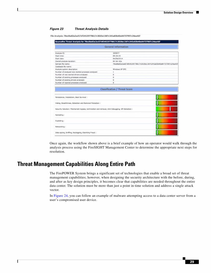
Figure 23 shows the details of a final analysis that results in a series of classifications/scorings of the suspected files. At this stage of the workflow, the operator can choose to take the appropriate action against the file.
28
Solution Design Overview
Figure 23 Threat Analysis Details
Once again, the workflow shown above is a brief example of how an operator would walk through the analysis process using the FireSIGHT Management Center to determine the appropriate next steps for resolution.
Threat Management Capabilities Along Entire PathThe FirePOWER System brings a significant set of technologies that enable a broad set of threat management capabilities; however, when designing the security architecture with the before, during, and after as key design principles, it becomes clear that capabilities are needed throughout the entire data center. The solution must be more than just a point in time solution and address a single attack vector.
In Figure 24, you can follow an example of malware attempting access to a data center server from a user’s compromised user device.
29

Solution Design Overview
Figure 24 Before, During, After Model in Action
1. FireAMP on the client performs file analysis on the client to identify and remove malware. The ISE performs user and device posturing with white listing of applications. User activity is sent to the FireSIGHT Management Center. FireAMP reports its findings to the FireSIGHT Management Center.
2. The Cisco switching fabric enforces the SGACLs and sends NetFlow records to the FireSIGHT Management Center and Lancope StealthWatch for traffic analysis.
3. Nexus 7000 to ASA/FirePOWER appliance cluster fabric connectivity prevents data black hole and inspection bypass.
4. Malware packets enter the ASA Cluster for extended access control list enforcement, traffic normalization, and protocol inspection.
5. Malware packets enter the FirePOWER appliance for Intrusion Prevention, Network AMP File Analysis, Application Detection and Control, File Trajectory, Network Trajectory, DLP on Sensitive Data.
6. The Secure Enclave Architecture provides for secure application tiering, east-west hypervisor layer security, east-west enclave security, automated secure workload provisioning, and service chaining. Leveraging the ASAv and the virtual FirePOWER appliance in the Secure Enclave Architecture further enhances protection.
Validated ComponentsSingle Site Clustering with TrustSec was a foundation for this validation. Additional components validated in this solution are listed in Table 3.
On CampusUser
PhysicalAccess
Compute
Storage
ConvergedNetwork Stack
Data Center Servers/Assets
ASA 55853D8250Cluster
DefenseCenter
Mgmt
SXPSXP &SGACLs
DC Core/AggCampus Core
Mobile User
Device PosturingFireAMP for fileAnalysisUser Logging
SGACLEnforcementNetFlowAnalysis
Policy ConsolidationTraffic NormalizationAsymetric TrafficFlow RedundancyASA Cluster
FireAMP on ServersSecure ApplicationTieringPort Profile SGTAssignmentsEast-West Protection
Intrusion PreventionNetwork AMP file AnalysisApplication Detectionand ControlIndications of CompromiseRetrospectionConnection IntelligenceFile TrajectoryNetwork Trajectory
SGACL EnforcementTrustSec SXPData Black HolePreventionOperationalEfficiency
UserIdentity
UserIdentity
3479
41
1 2
2
3 4 5
5
6
634
1
30

Threat Management with NextGen IPS Design Considerations
Threat Management with NextGen IPS Design ConsiderationsAs discussed above, it is critically important to keep threat capabilities uppermost in mind to build a system that can provide an effective response to the threats affecting the data center. This next section provides guidance on how to integrate the FirePOWER NextGen IPS appliance into the fabric. Next are discussed the capabilities provided by the advanced technologies and features of the FirePOWER appliance, as well as Advanced Malware Protection (AMP) for the endpoints. The goal is to show how to deploy the comprehensive set of Threat Management System capabilities to create a highly effective response to secure the data center.
FirePOWER Appliance and Management Platform Integration
Platform Management—FireSIGHT Management Center
A FireSIGHT Management Center provides a centralized management point and event database for the FirePOWER appliance deployment. FireSIGHT Management Centers aggregate and correlate intrusion, file, malware, discovery, connection, and performance data. This provides the capability to monitor the information that the FirePOWER appliances report in relation to one another, and to assess and control the overall activity that occurs on the network.
Key features of the FireSIGHT Management Center include:
• Device, license, and policy management
• Display of event and contextual information using tables, graphs, and charts
• Health and performance monitoring
• External notification and alerting
• Correlation, indications of compromise, and remediation features for real-time threat response
• Reporting
Table 3 Validated Components
Component Role Hardware ReleaseCisco Adaptive Security Appliance (ASA)
Data center firewall cluster
Cisco ASA 5585-SSP60
Cisco ASA Software Release 9.2
FirePOWER appliance NextGen IPS Platform 3D8250 5.3
FireSIGHT Management Center Appliance
NextGen IPS Platform Management
DC3500 5.3
FireAMP Endpoint Malware Protection
N/A Version XX
Cisco Nexus 7000 Aggregation and FlexPod access switch
Cisco 7004 NX-OS version 6.1(2)
Note Cisco FireSIGHT Management Center included licensing for FireSIGHT, Protection, Malware, Application and URL Control, so that these capabilities would be enabled on the FirePOWER appliance.
31

Threat Management with NextGen IPS Design Considerations
• High Availability (redundancy) feature can ensure continuity of operations
The FireSIGHT Management Center management of the FirePOWER physical and virtual appliances requires network connectivity for proper communication flows. Figure 25 demonstrates the information flows between the FirePOWER physical and virtual appliances and the FireSIGHT Management Center.
Figure 25 FireSIGHT Management Center and FirePOWER Appliance Flows
Using Redundant FireSIGHT Management Centers
Two FireSIGHT Management Centers can operate as a high availability pair to ensure redundant functionality in case one of the FireSIGHT Management Centers fails. Policies, user accounts, and more are shared between the two FireSIGHT Management Centers. Events are automatically sent to both FireSIGHT Management Centers.
FireSIGHT Management Centers periodically update each other on changes to their configurations, and any change made to one FireSIGHT Management Center should be applied on the other FireSIGHT Management Center within ten minutes. Each FireSIGHT Management Center has a five-minute synchronization cycle, but the cycles themselves can be out of synchronization by as much as five minutes, so changes appear within two five-minute cycles. During this ten-minute window, configurations may appear differently on the FireSIGHT Management Centers.
FireSIGHT Management Centers in a high availability pair share the following information:
• User account attributes
• Authentication configurations
• Custom user roles
• Authentication objects for user accounts and user awareness, as well as the users and groups that are available to user conditions in access control rules
• Custom dashboards
• Custom workflows and tables
3479
42
Device StatisticsCPUTrafficDiskMemory
PoliciesIntrusionNetwork DiscoveryAccess ControlSystemHealthFireSIGHT Management Center
Managed DeviceDiscovery DataHostApplicationUser Activity
EventsIntrusionDiscoveryHealthConnection Data
32

Threat Management with NextGen IPS Design Considerations
• Device attributes, such as the device’s host name, where events generated by the device are stored, and the group in which the device resides
• Intrusion policies and their associated rule states
• File policies
• Access control policies and their associated rules
• Local rules
• Custom intrusion rule classifications
• Variable values and user-defined variables
• Network discovery policies
• User-defined application protocol detectors and the applications they detect
• Activated custom fingerprints
• Host attributes
• Network discovery user feedback, including notes and host criticality; the deletion of hosts, applications, and networks from the network map; and the deactivation or modification of vulnerabilities
• Correlation policies and rules, compliance white lists, and traffic profiles
• Change reconciliation snapshots and report settings
• Intrusion rule, geolocation database (GeoDB), and vulnerability database (VDB) updates
The FireSIGHT Management Center appliances come in three models and have the performance ratings shown in Table 4.
Note Virtual FireSIGHT Management Center is available, and it supports managing up to 25 physical and/or virtual appliances. It is compatible with VMware ESX4.5/5.x or greater and requires at least four CPU cores and a minimum of 4GB of memory.
License Considerations
The topic of licensing products and applications is not typically covered in Cisco Validated Designs, but because the FirePOWER appliances support a comprehensive set of technologies and capabilities, a
Table 4 FireSIGHT Management Center Performance
DC750 DC1500 DC3500
Max devices managed 10 35 150
Max IPS events 20M 30M 150M
Event storage 100 GB 125 GB 400 GB
Max network map (hosts/users)
2k/2k 50k/50k 300k/300k
Max flow rate 2000 fps 6000 fps 10000 fps
High availability features
Lights-out Management (LOM)
RAID1, LOM, High Availability pairing (HA)
RAID 5, LOM, HA, Redundant AC power
33

Threat Management with NextGen IPS Design Considerations
brief discussion on licensing seemed appropriate for completeness of this document.
FireSIGHT
A FireSIGHT license is included with FireSIGHT Management Center and is required to perform host, application, and user discovery. The FireSIGHT license on FireSIGHT Management Center determines how many individual hosts and users can be monitored with the FireSIGHT Management Center and its managed devices, as well as how many users can be used to perform user control. (See Table 5.) Cisco recommends that licenses are added during the initial setup of FireSIGHT Management Center. Otherwise, any devices registered during initial setup are added to the FireSIGHT Management Center as unlicensed. After initial setup, licenses must be enabled individually on each device after the initial setup process is over.
Protection
A Protection license allows managed devices to perform intrusion detection and prevention, file control, and security intelligence filtering.
Control
A Control license allows managed devices to perform user and application control. It also allows devices to perform switching and routing (including DHCP relay), Network Address Translation (NAT), and to cluster devices and stacks. A Control license requires a Protection license.
URL Filtering
A URL Filtering license allows managed devices to use regularly updated cloud-based category and reputation data to determine which traffic can traverse the network, based on the URLs requested by monitored hosts. A URL Filtering license requires a Protection license.
Malware
A Malware license allows managed devices to perform network-based advanced malware protection (AMP). This capability enables the platform to detect, capture, and block malware files transmitted over the network and to submit those files for dynamic analysis. This capability allows the operator to view file trajectories, which track files transmitted over the network. A Malware license requires a Protection license.
Table 5 FireSIGHT Limits by FireSIGHT Management Center Model
FireSIGHT Management Center Model FireSIGHT Host and User LimitVirtual FireSIGHT Management Center 50,000
DC500 1000 (no user control)
DC750 2000
DC1000 20,000
DC1500 50,000
DC3000 100,000
DC3500 300,000
34

Threat Management with NextGen IPS Design Considerations
NextGen IPS Fabric Integration
When the FirePOWER appliances are deployed inline, the appliances can be used to affect the flow of traffic based on multiple criteria. The FirePOWER appliances offer threat management capabilities that far exceed those offered by traditional IPS devices. These capabilities are described in greater detail throughout the remainder of this document.
ASA Cluster Integration
The Single Site Clustering with TrustSec CVD provides extensive detailed information on design and deployment considerations for integrating the ASA 5585-X operating in the cluster mode. Since the release of that CVD, the ASA operating system has had a new release of version 9.2. The recent 9.2 release provides for increased scalability by supporting up to 16 active links with EtherChannel. This allows customers to scale up to 16 ASA 5585-Xs in the cluster for up to 640Gbps of bandwidth.
When deploying the ASA Cluster, all of the ASAs must have the exact same configurations for the ASA system to work properly. In addition, they should be deployed in a consistent manner. This applies to using the same type of ports on each unit to connect to the fabric. Use the same ports for the Cluster Control Link to the switching fabric and the same with the Data links. When the ASA Cluster is deployed properly, the master unit of the cluster replicates its configuration to the other units in the cluster, and so the cluster must have a consistent deployment across all the units.
ASA Cluster Performance
Adding a new ASA 5585-X into the cluster contributes to an increase of overall system throughput of about 70 percent of total processing capability of that unit. Throughput of an ASA 5585-X-SSP60 is 40Gbps of optimal traffic, jumbo frame or UDP, and approximately 20Gbps of IMIX/EMIX traffic. Maximum connections and connections per second have a scaling factor or 60 percent and 50 percent respectively. (See Table 6.)
ASA Cluster Health Status
The master unit monitors every unit in the cluster by sending keep alive messages over the cluster link. When the ASA interfaces are operating in spanned EtherChannel mode, the unit monitors the cLACP messages and reports a link status back to the master. With health monitoring enabled, the failed units are removed from the cluster automatically. If the master unit fails, another member of the cluster with the highest priority assumes the master role.
ASA to Traditional Cisco IPS Traffic Flow
As stated throughout this document, this solution is building on top of the Single Site with TrustSec architecture, and so it is critical that the integration of the FirePOWER appliances into the ASA
Table 6 ASA Cluster Performance
Function PerformanceASA 5585-X Firewall Throughput - Multiprotocol 20Gbps
ASA 5585-X 16 Node Cluster (IMIX/EMIX) 224Gbps
TCP Connections Per Second (1 chassis) 350K cps
ASA 5585-X 16 Node Cluster TCP cps 2.8M cps
Concurrent (Max) TCP Connections (1 chassis) 10M Max
ASA 5585-X Node Cluster Max Connections 96M Max
35
Threat Management with NextGen IPS Design Considerations
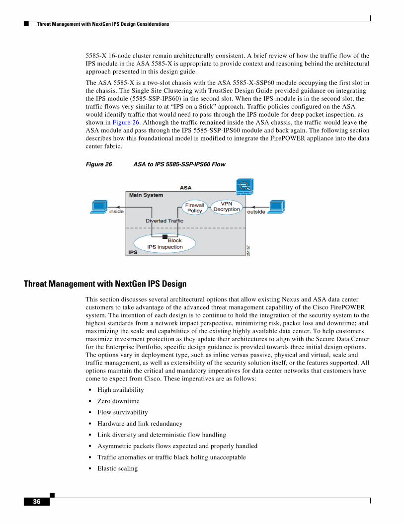
5585-X 16-node cluster remain architecturally consistent. A brief review of how the traffic flow of the IPS module in the ASA 5585-X is appropriate to provide context and reasoning behind the architectural approach presented in this design guide.
The ASA 5585-X is a two-slot chassis with the ASA 5585-X-SSP60 module occupying the first slot in the chassis. The Single Site Clustering with TrustSec Design Guide provided guidance on integrating the IPS module (5585-SSP-IPS60) in the second slot. When the IPS module is in the second slot, the traffic flows very similar to at “IPS on a Stick” approach. Traffic policies configured on the ASA would identify traffic that would need to pass through the IPS module for deep packet inspection, as shown in Figure 26. Although the traffic remained inside the ASA chassis, the traffic would leave the ASA module and pass through the IPS 5585-SSP-IPS60 module and back again. The following section describes how this foundational model is modified to integrate the FirePOWER appliance into the data center fabric.
Figure 26 ASA to IPS 5585-SSP-IPS60 Flow
Threat Management with NextGen IPS Design
This section discusses several architectural options that allow existing Nexus and ASA data center customers to take advantage of the advanced threat management capability of the Cisco FirePOWER system. The intention of each design is to continue to hold the integration of the security system to the highest standards from a network impact perspective, minimizing risk, packet loss and downtime; and maximizing the scale and capabilities of the existing highly available data center. To help customers maximize investment protection as they update their architectures to align with the Secure Data Center for the Enterprise Portfolio, specific design guidance is provided towards three initial design options. The options vary in deployment type, such as inline versus passive, physical and virtual, scale and traffic management, as well as extensibility of the security solution itself, or the features supported. All options maintain the critical and mandatory imperatives for data center networks that customers have come to expect from Cisco. These imperatives are as follows:
• High availability
• Zero downtime
• Flow survivability
• Hardware and link redundancy
• Link diversity and deterministic flow handling
• Asymmetric packets flows expected and properly handled
• Traffic anomalies or traffic black holing unacceptable
• Elastic scaling
36
Threat Management with NextGen IPS Design Considerations
• Low latency
• No default packet loss penalties for services
• Manageability/visibility/orchestration
• Security and regulatory compliance
The Threat Management with NextGen IPS options will be discussed in detail below and include:
• Option 1—FirePOWER in an inline design (ASA Cluster Context Pairing)
• Option 2—FirePOWER in a passive design
• Option 3—Virtual FirePOWER and virtual ASA design
On the following pages, each option is discussed in further detail, and a threat flow diagram is applied to show how the threat-centric approach is leveraged before, during, and after an attack.
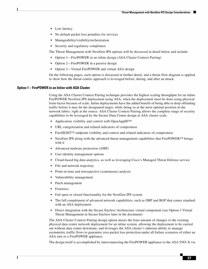
Option 1 – FirePOWER in an Inline with ASA Cluster
Using the ASA Cluster Context Pairing technique provides the highest scaling throughput for an inline FirePOWER NextGen IPS deployment using ASA, when the deployment must be done using physical form-factor because of scale. Inline deployments have the added benefit of being able to drop offending traffic before it may hit the designated target, while doing so at the most optimal position in the network fabric: right at the source. ASA Cluster Context Pairing allows the complete range of security capabilities to be leveraged by the Secure Data Center design at ASA cluster scale.
• Application visibility and control with OpenAppID™
• URL categorization and related indicators of compromise
• FireSIGHT™ endpoint visibility and context and related indicators of compromise
• NextGen IPS along with the advanced threat management capabilities that FirePOWER™ brings with it
• Advanced malware protection (AMP)
• User identity management options
• Cloud-based big data analytics, as well as leveraging Cisco’s Managed Threat Defense service
• File and network trajectory
• Point-in-time and retrospective (continuous) analysis
• Vulnerability management
• Patch management
• Forensics
• Fail open or closed functionality for the NextGen IPS system
• The full complement of advanced network capabilities, such as DRP and BGP that comes standard with an ASA deployment
• Direct integration with the Secure Enclave Architecture virtual component (see Option 3 Virtual Threat Management in Secure Enclave later in the document)
The ASA Cluster Context Pairing design option incurs the least amount of changes to the existing physical data center network deployment for an inline system, allowing the deployment to be carried out without data center downtime, and leverages the ASA cluster’s inherent ability to manage asymmetric traffic flows to guarantee zero packet loss protection under all failure scenarios of either an ASA unit or a FirePOWER appliance.
The design itself is accomplished by interconnecting the FirePOWER appliance to the ASA 5585-X via
37
Threat Management with NextGen IPS Design Considerations
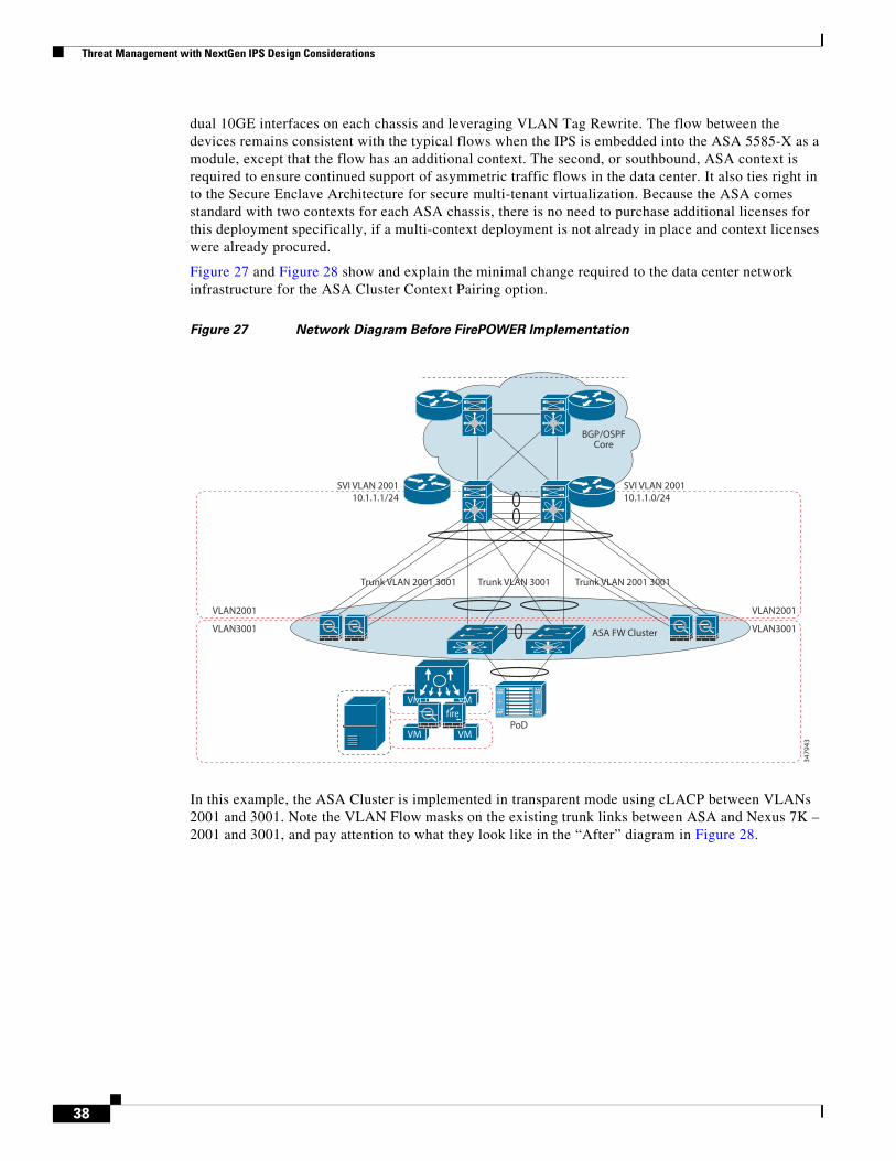
dual 10GE interfaces on each chassis and leveraging VLAN Tag Rewrite. The flow between the devices remains consistent with the typical flows when the IPS is embedded into the ASA 5585-X as a module, except that the flow has an additional context. The second, or southbound, ASA context is required to ensure continued support of asymmetric traffic flows in the data center. It also ties right in to the Secure Enclave Architecture for secure multi-tenant virtualization. Because the ASA comes standard with two contexts for each ASA chassis, there is no need to purchase additional licenses for this deployment specifically, if a multi-context deployment is not already in place and context licenses were already procured.
Figure 27 and Figure 28 show and explain the minimal change required to the data center network infrastructure for the ASA Cluster Context Pairing option.
Figure 27 Network Diagram Before FirePOWER Implementation
In this example, the ASA Cluster is implemented in transparent mode using cLACP between VLANs 2001 and 3001. Note the VLAN Flow masks on the existing trunk links between ASA and Nexus 7K – 2001 and 3001, and pay attention to what they look like in the “After” diagram in Figure 28.
VM VM
VM VM
Trunk VLAN 2001 3001 Trunk VLAN 2001 3001
ASA FW Cluster
3479
43
BGP/OSPFCore
Trunk VLAN 3001
SVI VLAN 2001SVI VLAN 200110.1.1.0/2410.1.1.1/24
VLAN2001
VLAN3001
VLAN2001
VLAN3001
PoD
38

Threat Management with NextGen IPS Design Considerations
Figure 28 Network Design ‘After’ FirePOWER Implemented
In Figure 28, the “After” diagram shows the minor changes are applied to the ASA Cluster Master. The ASAs will use a second (South) context to enable the asymmetric traffic handling to and from the FirePOWER appliances in both directions. VLAN 2001 will remain in the original context (unless multiple contexts were already in use); in such case, it will become a member of North Context (note: the North naming is arbitrary). VLAN 3001 will become a member of new South Context South (once again the South naming is arbitrary). A new VLAN will be added to each of these contexts 2101 to North and 3101 to South. You will notice that there are no gateway or VLAN changes on hosts, no trunk flow mask changes (pruning), and the solution will leverage the existing links on the ASA cluster that are already in place to attach to the Nexus 7K switches with no changes required.
The two new VLANs will be used to incorporate the FirePOWER appliance into the flow, effectively sandwiching the FirePOWER appliance between the North and South ASA Contexts. This is done to ensure that asymmetric traffic flow management will happen on both sides of the FirePOWER appliances by leveraging the inherent capabilities of the ASA Cluster CCL asymmetric reassembly. The FirePOWER appliance will be added to a new physical 10G port on each ASA and assigned to each ASA context, providing a network backplane-style flow that leverages the highly optimized flow semantics of the ASA cluster.
FirePOWER Appliance VLAN Tag Switching
The FirePOWER appliances can be configured for a Layer 2 deployment so that it provides packet switching between two or more network segments. In the ASA Cluster Context Pairing deployment, you configure switched interfaces and virtual switches on managed devices to operate as standalone broadcast domains. A virtual switch uses the MAC address from a host to determine where to send packets. In this case, the ASA is the host referenced. This Layer 2 deployment of the FirePOWER appliance is used to switch the VLAN tags between the two 10G Ethernet interfaces on FirePOWER appliance to the dedicated 10G interfaces on the local ASA. (See Figure 29.)
VM VM
VM VM
Trunk VLAN 2001 3001
South Context 3001, 3101
North Context 2001, 2101
South Context 3001, 3101
North Context 2001, 2101
Trunk VLAN 2001 3001
ASA FWCluster
3479
44
BGP/OSPFCore
DC Edge
Trunk VLAN 3001
SVI VLAN 2001SVI VLAN 200110.1.1.0/2410.1.1.1/24
VLAN2001
VLAN3001
VLAN2001
VLAN3001
PoD
39

Threat Management with NextGen IPS Design Considerations
Figure 29 ASA 5585-X to 3D8250 Flow
Figure 30 demonstrates the communication through the ASA 5585-X Cluster with the FirePOWER appliance integrated as follows.
Packet Flow
1. Packet arrives on SVI VLAN 2001–ARP request to server 10.11.1.88–ASA replies with outside interface MAC address
2. Passes through ASA North Context 1 to FirePOWER VLAN 2101 using physical interface destined to ASA South Context 2–packet arriving on VLAN 2001 on ASA are policy processed on ASA – (Clustering Owner/Director) and so on. Maintains symmetric flow for this session.
3. Packet inspected by FirePOWER appliance forwarded to (outside/inside) ASA context 2 interface –switches VLAN TAG to 3101
4. ASA Context 2 processes policy, retags packet on trunk to VL3001–sent back to Nexus7K with VLAN 3001
5. Nexus7K forwards packet to server over VLAN 3001
6. Packet reaches server 10.11.1.88
3479
39
ASA 5585-X
inside outside
FirewallPolicy
FirewallPolicy
SouthContext
10GE 10GE
Sourcefire3D 8250 Sensor
NorthContext
VLAN 2101VLAN 3101
VLAN 2001VLAN 3001
Flow Inspection
VPNDecryption
40

Threat Management with NextGen IPS Design Considerations
Figure 30 Packet Flow
Asymmetric Traffic Flow Handling for Secure Flows
In a properly designed highly available data center, asymmetric traffic flows are not only expected, but in many cases, desirable so that one may take full advantage of their significant investment in data center network switching components and most granular use of scalable (up)links. Because sessions are always two-way, there is always a possibility that even traffic from the same source and destination, based upon symmetric LACP hashes, will take a different physical path on the return trip. From a security standpoint, accuracy always rules the game, whereby a system such as a NextGen IPS cannot provide you with complete visibility nor can it take appropriate action on packets it does not see. This kind of accuracy does not have a very high tolerance for missing packets that took an alternate path. Leveraging ASA Cluster Context Pairing effectively sandwiches the FirePOWER appliance between two logical ASA clusters. This allows the inherent asymmetric traffic flow handling that the cluster provides to be used to guarantee that every packet in a session is always seen by the correct FirePOWER appliance. This holds true regardless of the direction of travel between source and destination for a given application session. When the FirePOWER appliance sees every packet in a session without exception, the accuracy required to provide complete security proficiency is the result. Figure 31 shows an example of traffic flow asymmetry between source and destination and how the ASA Cluster Context Pair guarantees the stickiness of each session by using the ASA CCL.
VLAN 3001 10.1.1.88
6VM VM
VM VM
Trunk VLAN 2001 3001 Trunk VLAN 2001 3001
3479
46
DC Edge
BGP/OSPFCore
ASA 1 ASA N
Context 1- North
Trunk VLAN 3001
Context 2- South
SVI VLAN 2001 10.1.1.1/24SVI VLAN 2001 10.1.1.1/24
VLAN2001
VLAN3101
VLAN2101
VLAN3001
VLAN2001
VLAN3101
VLAN2101
VLAN3001
PoD
1
3
4
5
2
41

Threat Management with NextGen IPS Design Considerations
Figure 31 Asymmetric Flow Handling within ASA Cluster Context Pair
Packet Flow
1. Packet originating from Source host is sent by local switch across a path to ASA A1 for policy processing and, assuming the policy is allowed and the initial disposition is presumed clean by the FirePOWER appliance, is forwarded.
2. Clean packet arrives on Destination host following expected path.
3. Destination host sends return trip packet.
4. Local switch chooses a path that eventually allows the packet to arrive on ASA A2.
5. ASA A2, using the CCL semantics for asymmetric reassembly, forwards the packet across the CCL, where packet arrives on the correct ASA A1 for processing.
6. Packet is sent through the Context Pair using the correct path so the FirePOWER appliance is able to see all packets in the session and provide accurate security assessment of flow.
7. Clean packet arrives on Source as expected.
Design Option – ASA Cluster Pair with No Additional VLANs
If the Secure Enclave Architecture for Multi-Tenant virtualization is not in use or is not planned, it is possible to deploy the ASA Cluster pair by using just the two previous VLANS, in this case 2001 and 3001. In this design option, as shown in Figure 32, the interfaces that connect to the FirePOWER appliance from the ASA are dedicated physical interfaces assigned to the North and South context with no VLAN Tags assigned. This design option also does not require that the FirePOWER appliance perform any VLAN Tag Switching. The EEM configuration still applies to this design option.
A1A1
2
A2
61
73 4
5A2
3479
47
ASA 5585-X
inside outside
SourceDestination
SouthContext
10GE 10GE
Sourcefire3D 8250 Sensor
NorthContext
VLAN 2001VLAN 3001
VLAN 2101VLAN 3101Flow Inspection
ASA 5585-X
inside outside
CCL
FirewallPolicy
FirewallPolicy
SouthContext
10GE 10GE
Sourcefire3D 8250 Sensor
NorthContext
VLAN 2001VLAN 3001
VLAN 2101VLAN 3101Flow Inspection
VPNDecryption
FirewallPolicy
FirewallPolicy
VPNDecryption
42

Threat Management with NextGen IPS Design Considerations
Figure 32 ASA Cluster Context Pair without Additional VLANs
Figure 33 demonstrates the communication flow through the ASA 5585-X Cluster with the FirePOWER appliance when deployed without additional VLAN tags assigned.
Note This option would not be validated in the deployment guides.
Packet Flow
1. Packet arrives on SVI VLAN 2001–ARP request to server 10.1.1.88–ASA replies with outside interface MAC address.
2. Passes through ASA North Context 1 to SF using physical interface destined to ASA South Context 2–Packet arriving on VLAN 2001 on ASA are policy processed on ASA–(Clustering Owner/Director) and so on. Maintains symmetric flow for this session.
3. Packet inspected by FirePOWER appliance forwarded to (outside/inside) ASA context 2 interface.
4. ASA Context 2 processes policy, retags packet on trunk to VL3001–sent back to Nexus7K with VLAN 3001.
5. Nexus 7K forwards packet to server over VLAN 3001.
6. Packet reaches server 10.1.1.88.
3479
48
ASA 5585-X
inside outside
FirewallPolicy
FirewallPolicy
SouthContext
10GE 10GE
Sourcefire3D 8250 Sensor
NorthContext
VLAN 2001VLAN 3001
Flow Inspection
VPNDecryption
43

Threat Management with NextGen IPS Design Considerations
Figure 33 Packet Flow for ASA Cluster Context Pair without Additional VLANs
IPS Fail Open
It is very important to ensure that traffic is not blocked in the event of a device failure. The following module type was selected because of the ability of the interface module to be able to fail “open” to that traffic is not blocked. The bandwidth of the interface was selected because of the port configurations of the ASA 5585-X as well as the port configurations on the associated Nexus 7000:
• Dual-port 10GBASE MM fiber interfaces with configurable bypass capability
Additional interfaces with configurable bypass are available but may not match the throughput of this design are as follows:
• Quad-port 1000BASE-T copper interface with configurable bypass capability
• Quad-port 1000BASE-SX fiber interface with configurable bypass capability
• Dual-port 40GBASE-SR4 fiber interface with configurable bypass capability (2U devices only)
Note that the 8200 Series platforms have Quad 10G modules available but they do not support the bypass capability.
Embedded Event Manager Optional Deployment
In the event of a FirePOWER appliance failure or link failure between the ASA and the FirePOWER appliance, there could potentially be a delay of nine seconds in the ASA Cluster’s Health Status checks prior to the ASA pulling itself and the FirePOWER appliance from the cluster. This delay exists because of an EtherChannel recovery mechanism that exists on the ASA. Even though the interfaces connecting the ASA VLAN 2101 (North) and ASA VLAN 3101 (South) to the FirePOWER appliance are both single, dedicated interfaces, a requirement of configuring ASA Cluster Data Plane interfaces is
VLAN 3001 10.1.1.88
6VM VM
VM VM
Trunk VLAN 2001 3001 Trunk VLAN 2001 3001
3479
49
DC Edge
BGP/OSPFCore
ASA 1 ASA N
Context 1- North
Trunk VLAN 3001
Context 2- South
SVI VLAN 2001 10.1.1.1/24SVI VLAN 2001 10.1.1.1/24
VLAN2001
VLAN3001
VLAN2001
VLAN3001
PoD
1
3
4
5
2
44

Threat Management with NextGen IPS Design Considerations
to put them into an EtherChannel. This is an EtherChannel of one, but an EtherChannel nonetheless. Because EtherChannel recovery mechanisms on the ASA use timers to allow a failed link to recover and to rejoin the bundle, the timers still apply. The default (and minimum) timer value is 9 seconds for EtherChannel link recovery on the ASA at this time. While work is progressing to modify this timer in future versions of ASA code, this delay can easily be eliminated completely by leveraging EEM to monitor the interface. The recommendation is to establish a secondary links of any speed on the ASA and FirePOWER appliance into the Nexus 7000 using an isolated VLAN where an EEM script can monitor for failures and provide immediate recovery of this single-link EtherChannel.
EEM offers the ability to monitor events and take informational or corrective action when the monitored events occur or when a threshold is reached. An EEM policy is an entity that defines an event and the actions to be taken when that event occurs (see Figure 34). There are two types of EEM policies: an applet or a script. An applet is a simple form of policy that is defined within the CLI configuration. A script is a form of policy that is written in Tool Command Language (Tcl).
Figure 34 EEM Policy
Note Although the ASA has implemented a lite version of EEM, this solution is using the EEM on the Nexus 7000 that has a full implementation of EEM.
Figure 35 shows the FirePOWER appliance between the North and Southbound contexts for Enclave 1, with additional connectivity to the Nexus 7000 into a dedicated EEM VLAN. Once the connectivity is established, configuring the Nexus 7000 with an EEM script such as the one in the diagram removes the nine-second delay in the case of a failure of the FirePOWER appliance.
45

Threat Management with NextGen IPS Design Considerations
Figure 35 EEM Deployment
The Flow Associated with Integrated Threat Defenses—Before, During, After the Attack
Figure 36 is an example of malware attempting access to a data center server from a user’s compromised user device through the ASA Cluster Context Pairing option. In the figure, you can follow the elements of Before, During, and After as they apply to the ASA Cluster Context Pairing deployment option. The process assumes that a connection from North of the DC Edge is attempting to access a file or application on a target server in the data center access layer.
Packet Flow
1. Server request to 10.1.1.88 arrives on Nexus 7000. Normal Layer 3 and Layer 2 processes are followed that directs the request to arrive on North Context ASA for policy processing on VLAN 2001.
2. The ASA executes policy checks, reducing the attack surface by checking allowed source/destination, protocol, ports, SGT information, and so on. Once request is confirmed as allowed, packet(s) are retagged to VLAN 2101 and packet(s) forwarded towards the South cluster pair using MAC address of NextGen IPS.
3. Packet(s) in the request are processed by the NextGen IPS, providing the complete battery of inline security checks, scanning, and management. This step includes all of the elements of the threat management system, including, but not limited to, application visibility, geolocation policies, advanced malware protection, IoC, device context(s), trajectory, and so on. If initial disposition is good, packet(s) are retagged to VLAN 3101and forwarded to South ASA Context MAC address.
4. Packet(s) arrive on South ASA Context and any additional policy checks could be completed.
5. Once policies are confirmed, South Context ASA retags packet(s) to VLAN 3001 and forwards to Nexus 7000 for delivery to destination server 10.1.1.88.
3479
51
ASA 5585-X (ASA1)Enclave 1
North Context
ASA 5585-X (ASA1)Enclave 1
South Context
VLAN 2001
VLAN 2101
VLAN 3101
VLAN 3001
Same Physical ASARepeated for eachASA in Cluster
(Applet Script Per ASA in Cluster)
event manager applet Track_SF1_ASA1_Down event track 1 state down action 1 syslog msg EEM applet Track_SF1_ASA1_Down shutting down ASA1 CCL action 2 cli conf term action 3 cli interface port-channel 40 action 4 cli shut
event manager applet Track_SF2_ASA2_Down event track 2 state down action 1 syslog msg EEM applet Track_SF2_ASA2_Down shutting down po41 action 2 cli conf term action 3 cli interface port-channel 41 action 4 cli shut
10GE PhysicalInterfaces on ASA &3D8250
EEM VLAN
Nexus 7K
46

Threat Management with NextGen IPS Design Considerations
6. Once packet arrives in the Access Layer, the Secure Enclave Architecture can provide for secure application tiering, east-west hypervisor layer security, east-west enclave security via the ASAv and Virtual FirePOWER appliance, automated secure workload provisioning and service chaining. AMP on endpoints may also play a role here. Port profile SGT assignments can also be leveraged if using Nexus 1000v. For more information on this step, see the Secure Enclave Architecture Design Guide.
Figure 36 Threat Flow in ASA Cluster Context Pairing – Before, During, and After
For additional detail on each of the before, during, and after components, see the Threat Management System Capabilities later in this document.
Option 2—FirePOWER Appliances in Passive Design
Option 2, using the FirePOWER system in a passive design model, provides the highest scaling throughput with minimal latency impacts when the deployment must be done using physical form-factor due to scale requirements. Additionally, it may be desirable to monitor traffic flows at the virtualization layer and this design option provides for that as well.
Passive deployments do not have the ability to drop offending traffic before it may hit the designated target, but they do provide a high degree of confidence when threat visibility is the primary concern and it is acceptable to take manual action against outbreak. The passive design still allows a formidable
VM VM
VM VM
Trunk VLAN 2001 3001 Trunk VLAN 2001 3001
3479
52
DC Edge
BGP/OSPFCore
ASA 1 ASA N
Context 1- North
Trunk VLAN 3001
Context 2- South
SVI VLAN 2001 10.11.1.1/24SVI VLAN 2001 10.11.1.1/24
VLAN2001
VLAN3101
VLAN2101
VLAN3001
VLAN 3001 10.1.1.88
VLAN2001
VLAN3101
VLAN2101
VLAN3001
PoD
1
2
3
4
5
6
- Security Policy Consolidation- Reduced Attack Surface- Traffic Normalization- Asymmetric Traffic Mitigation- Security Flow Redundancy- ASA Cluster Scaling
- FireAMP on Servers- Secure Application Tiering- Port Profile SGT Assignments- East-West Protection- Server Policy Consolidation- Next Gen Intrusion Prevention
Before
- Next-Gen Intrusion Prevention- Network AMP file Analysis- Application Detection and Control- Indications of Compromise- Retrospection- Connection Intelligence- Network File Trajectory- Device Trajectory
Fire Control Policies
Host Profiles
White Lists
Device Posture Assessment
Device Compliance Checks
Application Control
During
Application Detection
SSL Detection
Sensitive Data Detection and Control
Network File Trajectory
After
Network File Trajectory
SSL Detection
Sensitive Data Detection and Control
Client File Trajectory
Enforcement User Notification
47

Threat Management with NextGen IPS Design Considerations
set of security capabilities to be leveraged by the Secure Data Center design at ASA Cluster scale:
• Application visibility and control with OpenAppID™
• URL categorization and related indicators of compromise
• FireSIGHT™ endpoint visibility and context and related indicators of compromise
• Anti-virus and anti-malware
• NextGen IPS along with the advanced threat management capabilities that FirePOWER™ brings with it
• Advanced malware protection (AMP)
• User identity management options
• Cloud-based big data analytics, as well as leveraging Cisco’s Managed Threat Defense service
• File and network trajectory
• Point-in-time and retrospective (continuous) analysis
• Vulnerability management
• Patch management
• Forensics
In Figure 37, a redundant pair of FirePOWER appliances is implemented in an active/standby configuration. A SPAN monitor session is created on each of the core Nexus 7000 switches. Nexus 7000 allows up to 48 monitor sessions, and like most other Cisco switches, allows both multiple source interfaces/VLANs and multiple destination interfaces/VLANs as well as monitoring traffic flows TX, RX or traffic in ‘both’ directions. The option, as laid out in Figure 37, will have visibility into all traffic that crosses through the core to/from any aggregation layer or the edge. Optionally, virtual FirePOWER appliances may be configured in monitor mode to allow visibility into East/West traffic from the access layer. FireSIGHT Management Center monitors all of these systems and provides a single-source of truth for all data collected. The example below accounts for several failure scenarios including: Nexus 7000 Chassis, any uplink between core and aggregation, FirePOWER appliance failure, or a failure of any interface in the equation. A basic configuration is provided in Figure 37. More details on configuring Nexus 7000 SPAN can be found at the following URL: http://www.cisco.com/c/en/us/support/docs/switches/nexus-7000-series-switches/113038-span-nexus-config.html.
Figure 37 shows both physical north-south and virtualization layer east-west flows being monitored.
48
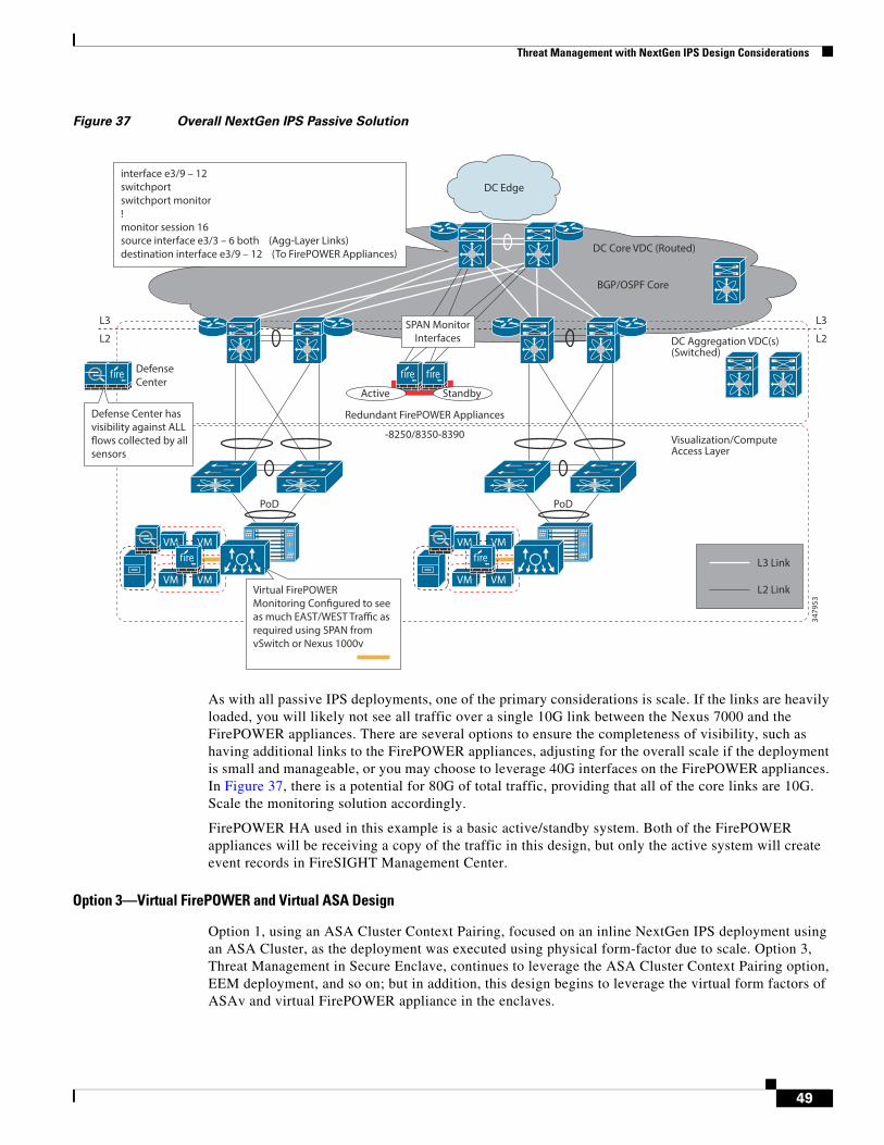
Threat Management with NextGen IPS Design Considerations
Figure 37 Overall NextGen IPS Passive Solution
As with all passive IPS deployments, one of the primary considerations is scale. If the links are heavily loaded, you will likely not see all traffic over a single 10G link between the Nexus 7000 and the FirePOWER appliances. There are several options to ensure the completeness of visibility, such as having additional links to the FirePOWER appliances, adjusting for the overall scale if the deployment is small and manageable, or you may choose to leverage 40G interfaces on the FirePOWER appliances. In Figure 37, there is a potential for 80G of total traffic, providing that all of the core links are 10G. Scale the monitoring solution accordingly.
FirePOWER HA used in this example is a basic active/standby system. Both of the FirePOWER appliances will be receiving a copy of the traffic in this design, but only the active system will create event records in FireSIGHT Management Center.
Option 3—Virtual FirePOWER and Virtual ASA Design
Option 1, using an ASA Cluster Context Pairing, focused on an inline NextGen IPS deployment using an ASA Cluster, as the deployment was executed using physical form-factor due to scale. Option 3, Threat Management in Secure Enclave, continues to leverage the ASA Cluster Context Pairing option, EEM deployment, and so on; but in addition, this design begins to leverage the virtual form factors of ASAv and virtual FirePOWER appliance in the enclaves.
VM VM
VM VM
StandbyActive
VM
VM
VM
VM
3479
53
DC Edge
BGP/OSPF Core
DC Core VDC (Routed)
DC Aggregation VDC(s)(Switched)
L2
L3
L2
L3
Visualization/ComputeAccess Layer
PoD
interface e3/9 – 12switchportswitchport monitor!monitor session 16source interface e3/3 – 6 both (Agg-Layer Links)destination interface e3/9 – 12 (To FirePOWER Appliances)
SPAN MonitorInterfaces
L3 Link
L2 Link
Redundant FirePOWER Appliances
-8250/8350-8390
DefenseCenter
PoD
Virtual FirePOWER Monitoring Configured to see as much EAST/WEST Traffic as required using SPAN from vSwitch or Nexus 1000v
Defense Center has visibility against ALL flows collected by all sensors
49

Threat Management with NextGen IPS Design Considerations
Note Complete details of the Secure Enclave Architecture is provided in the Cisco Validated Design: Secure Data Center for the Enterprise: Secure Enclaves Architecture.
This section provides a summary of the option because it leverages the ASA Cluster Context Pairing, and both the ASAv and virtual FirePOWER appliances are capable of exactly the same integrated threat defenses and, in the case of virtual FirePOWER appliance, all threat management workflows are managed by a central FireSIGHT Management Center Management Platform. Like the ASA Cluster Context Pairing option, the Virtual FirePOWER and Virtual ASA Design Option takes advantage of a similar collection of integrated threat functions:
• Application visibility and control with OpenAppID™
• URL categorization and related indicators of compromise
• FireSIGHT™ endpoint visibility and context and related indicators of compromise
• Anti-virus and anti-malware
• NextGen IPS along with the advanced threat management capabilities that FirePOWER™ brings with it
• Advanced malware protection (AMP)
• User identity management options
• Cloud-based big data analytics, as well as leveraging Cisco’s Managed Threat Defense service
• File and network trajectory
• Point-in-time and retrospective (continuous) analysis
• Vulnerability management
• Patch management
• Forensics
• Fail open or closed functionality for the NextGen IPS system
• The full complement of advanced network capabilities, such as DRP and BGP that comes standard with an ASA deployment
• Direct integration with the Secure Enclave Architecture virtual component
In addition, this design option provides integration with virtualization platforms:
• VXLAN
• Service Chaining
• vMotion
• Secure Group Tag mapping in port profiles
Figure 38 shows an example of the Virtual Threat Management in the Secure Enclave Architecture. You will notice that there are VLAN pairs for each Enclave, some routed and some transparent, and there is an emphasis on the virtualization component.
50

Threat Management with NextGen IPS Design Considerations
Figure 38 ASA Cluster Context Pairing Tied to Secure Enclave Architecture
FirePOWER Appliance Performance Design Considerations
Table 7 provides a foundation for the FirePOWER appliance performance as advertised. Although a single 3D8250 throughput is advertised for 10Gbps, by integrating the device into the ASA Cluster, maximum throughput has a range from 10Gbps up to 160Gbps, thus allowing a customer to scale the system as the business grows.
3479
54
To Core and Clients
Enclave 1Transparent
VLAN 2001
VLAN 2101
VLAN 3101
VLAN 3001
Enclave 2Transparent
VLAN 2002
VLAN 2102
VLAN 3102
VLAN 3002
Enclave 3Routed
cLACP
North Context
South Context
FirePOWER
VLAN 2003 VLAN 200310.11.3.192
VLAN 300310.11.3.254
VLAN 210310.11.103.194/30
VLAN 310310.11.103.193/30
VLAN 2103
VLAN 3103
VLAN 3003
VLAN 2001 10.11.255.254/24VLAN 2001 10.11.2.254/24VLAN 2001 10.11.3.254/24
OSPF AREA 2000 NSSA
ASA Cluster Data Plane EtherChannel
To Enclave ServersVLAN 3001 VLAN 3002 VLAN 3003
Table 7 FirePOWER Appliance Performance
Function PerformanceIPS throughput 10Gbps
IPS throughput when in ASA 5585-X 16-node cluster 160Gbps
Firewall only (No IPS) 20Gbps
TCP connections per second 180,000
TCP connection/second in ASA 5585-X 16-node cluster 2,800,000
51

Threat Management with NextGen IPS Design Considerations
Low Latency Implementation
While the ultimate lowest latency deployment would be the Passive deployment option as discussed above, the FirePOWER appliances can be tuned for lower latency. A balance of security with the need to maintain latency at an acceptable level can be achieved by enabling rule latency thresholding. Rule latency thresholding measures the elapsed time each rule takes to process an individual packet, suspends the violating rule along with a group of related rules for a specified time if the processing time exceeds the rule latency threshold a configurable consecutive number of times, and restores the rules when the suspension expires.
Rule latency thresholding measures elapsed time, not just processing time, to more accurately reflect the actual time required for the rule to process a packet. However, latency thresholding is a software-based latency implementation that does not enforce strict timing.
When you enable packet latency thresholding, a timer starts for each packet when decoder processing begins. Timing continues either until all processing ends for the packet or until the processing time exceeds the threshold at a timing test point.
As illustrated in Figure 39, packet latency timing is tested at the following test points:
• After the completion of all decoder and preprocessor processing and before rule processing begins.
• After processing by each rule. If the processing time exceeds the threshold at any test point, packet inspection ceases.
Figure 39 Packet Latency
Packet latency thresholding can improve system performance in both passive and inline deployments, and can reduce latency in inline deployments, by stopping inspection of packets that require excessive processing time. These performance benefits might occur when, for example:
• For both passive and inline deployments, sequential inspection of a packet by multiple rules requires an excessive amount of time
• For inline deployments, a period of poor network performance, such as when someone downloads an extremely large file, slows packet processing
Concurrent TCP connections 12,000,000
Concurrent TCP connections in an ASA 5585-X 16-node cluster 96,000,000
Table 7 FirePOWER Appliance Performance
Rule 1 Rule 2 Rule n
3479
55
EventDatabase
Preprocessors
Rules Engine
Managed Device
Packet Latency TimerStart Test Test Test Test
PacketDecoder
52

Threat Management with NextGen IPS Design Considerations
Communication Ports Requirements
Specific features of the FirePOWER appliances require an Internet connection and are configured by default to directly connect to the Internet.
Additionally, the FirePOWER appliances require that certain ports remain open for two-way communications between FirePOWER appliances. This two-way communication is an SSL-encrypted communication channel and uses port 8305/TCP. In general, feature-related ports remain closed until enabled or the associated feature is configured.
While the FirePOWER appliances allow for the modification of communication ports, care should be taken when making changes because this can have negative impacts on the deployment. For example, closing port 25/TCP (SMTP) outbound on a managed device blocks the device from sending email notifications for individual intrusion events.
As another example, access to a physical managed device’s web interface can be disabled by closing port 443/TCP (HTTPS), but this also prevents the device from submitting suspected malware files to the cloud for dynamic analysis.
Custom ports can be configured for LDAP and RADIUS authentication when a connection is configured between the system and the authentication server. The management port (8305/TCP) can be changed; however; Cisco strongly recommends that the default setting is kept. If the management port is changed, it must be changed for all of the FirePOWER appliances in the network that need to communicate with each other. Port 32137/TCP can be used to allow upgraded FireSIGHT Management Centers to communicate with the Sourcefire Cloud. However, Cisco recommends that the communications port be switched to port 443.
For more information, see the “Default Communication Ports for Sourcefire 3D System Features and Operations Table” in the Sourcefire 3D System Users Guide.
Management Network
To safeguard the FireSIGHT Management Center, the appliance should be installed on a protected management network. Although the FireSIGHT Management Center is configured to have only the necessary services and ports available, steps must be taken to make sure that attacks cannot reach it (or any managed devices) from outside the firewall. If the FireSIGHT Management Center and its managed devices reside on the same network, the management interfaces on the devices can be connected to the same protected management network as the FireSIGHT Management Center. Steps must be taken ensure that communications between FirePOWER appliances cannot be interrupted, blocked, or tampered with; for example, with a distributed denial of service (DDoS) or man-in-the-middle attack.
SNMP
Simple Network Management Protocol (SNMP) polling of an appliance can be enabled using the system policy. The SNMP feature supports use of versions 1, 2, and 3 of the SNMP protocol. Enabling the system policy SNMP feature does not cause the appliance to send SNMP traps; it only makes the information in the MIBs available for polling by the network management system. SNMP access must be added for any computer that will poll the appliance. The SNMP MIB contains information that could be used to attack the FirePOWER appliances. Cisco recommends limiting the access list for SNMP access to the specific hosts that will be used to poll for the MIB. Sourcefire also recommends the use of SNMPv3 and use strong passwords for network management access.
Cisco-Sourcefire Cloud Communications
The FirePOWER appliance contacts the Cisco-Sourcefire cloud to obtain various types of information:
53

Threat Management with NextGen IPS Design Considerations
• If the organization has a FireAMP subscription, the system can receive endpoint-based malware events.
• File policies associated with access control rules allow managed devices to detect files transmitted in network traffic.
• The FireSIGHT Management Center uses data from the Cisco-Sourcefire cloud to determine whether the files represent malware.
• When URL filtering is enabled, the FireSIGHT Management Center can retrieve category and reputation data for many commonly visited URLs, as well as perform lookups for uncategorized URLs.
Automatic Updates
Automatic updates allow the system to contact the Cisco-Sourcefire cloud on a regular basis to obtain updates to the URL data in the FirePOWER appliance local data sets. Although the cloud typically updates its data once per day, enabling automatic updates forces the FireSIGHT Management Center to check every 30 minutes to make sure that the system always has up-to-date information. Although daily updates tend to be small, if it has been more than five days since the last update, new URL filtering data may take up to 20 minutes to download, depending on bandwidth. Then, it may take up to 30 minutes to perform the update itself.
Note Cisco recommends that automatic updates are used, or the scheduler is used to schedule updates on a regular basis to provide the most up-to-date, relevant URL data.
Share URI Information
Optionally, FireSIGHT Management Centers can send information about the files detected in network traffic to the Cisco-Sourcefire cloud. This information includes URI information associated with detected files and their SHA-256 hash values. Although sharing is opt-in, transmitting this information to Cisco will help with future efforts to identify and track malware.
Internet Access and High Availability
The system uses ports 80/HTTP and 443/HTTPS to contact the Cisco-Sourcefire cloud and also supports use of a proxy. Although all URL filtering configurations and information are synchronized between FireSIGHT Management Centers in a high availability deployment, only the primary FireSIGHT Management Center downloads URL filtering data. If the primary FireSIGHT Management Center fails, make sure that the secondary FireSIGHT Management Center has direct access to the Internet, and use the web interface on the secondary FireSIGHT Management Center to promote it to Active.
FireSIGHT Management Centers in a high availability pair do not share cloud connections nor malware dispositions. To ensure continuity of operations, and to ensure that detected files’ malware dispositions are the same on both FireSIGHT Management Centers, both primary and secondary FireSIGHT Management Centers must have access to the cloud.
Threat Management System Capabilities—Design ConsiderationsWith the FirePOWER appliance properly integrated into the fabric, the focus is now on enabling those capabilities and looking at how they provide a threat response across the attack continuum. The following sections provide design guidance on capabilities with a mapping of each capability to the
54

Threat Management with NextGen IPS Design Considerations
phases in the attack continuum. Some capabilities span across multiple phases, as indicated in the mapping.
Threat Containment and Remediation
Security Intelligence Lists and Feeds—Attack Continuum Mapping: Before, During
The Security Intelligence feature allows, on a per access control policy, specified traffic that can traverse the network based on the source or destination IP address. This is especially useful to blacklist specific IP addresses, before the traffic is subjected to analysis by access control rules. Similarly, IP addresses can be added to the whitelist to force the system to handle their connections using access control.
A global whitelist and global blacklist are included by default in every access control policy, and apply to any zone. Additionally, within each access control policy, a separate whitelist and blacklist can be created using a combination of network objects and groups as well as Security Intelligence lists and feeds, all of which can be constrained by security zone.
A Security Intelligence feed is a dynamic collection of IP addresses that the FireSIGHT Management Center downloads from an HTTP or HTTPS server at configurable intervals. Because feeds are regularly updated, the FirePOWER system can use up-to-date information to filter the network traffic. To help build blacklists, Cisco provides the Security Intelligence Feed, which represents IP addresses determined by the Sourcefire VRT to have a poor reputation.
Network-Based Advanced Malware Protection—Attack Continuum Mapping: Before, During
Network-based advanced malware protection (AMP) allows the system to inspect network traffic for malware in several types of files. Appliances can store detected files for further analysis, either to their hard drive or a malware storage pack. Regardless of whether a detected file is stored, it can be submitted to the Cisco-Sourcefire cloud for a simple known-disposition lookup using the file’s SHA-256 hash value. Files can also be submitted for dynamic analysis, which produces a threat score as discussed later in this section. Using this contextual information, the system can configured the system to block or allow specific files. Malware protection is configured as part of the overall access control configuration; file policies associated with access control rules inspect network traffic that meets rule conditions. Figure 40 demonstrates the communication flows between the Cisco-Sourcefire cloud, FireSIGHT Management Center, Network AMP, and the endpoints.
55

Threat Management with NextGen IPS Design Considerations
Figure 40 Malware Information Flow
FireAMP—Attack Continuum Mapping: Before, During
Although the endpoint protection is considered outside of the scope of the data center architecture design, the topic is included because these devices are accessing the data center assets, so it is critical that these devices are included in the overall discussion.
FireAMP is Cisco’s enterprise-class, advanced malware analysis and protection solution that discovers, understands, and blocks advanced malware outbreaks, advanced persistent threats, and targeted attacks. If the organization has a FireAMP subscription, individual users install FireAMP Connectors on their computers and mobile devices (also called endpoints). These lightweight agents communicate with the Cisco-Sourcefire cloud, which in turn communicates with the FireSIGHT Management Center. After the FireSIGHT Management Center is configured to connect to the cloud, the FireSIGHT Management Center web interface is used to view endpoint-based malware events generated as a result of scans, detections, and quarantines on the endpoints. The FireSIGHT Management Center also uses FireAMP data to generate and track indications of compromise on hosts, as well as display network file trajectories.
Use the FireAMP portal (http://amp.sourcefire.com/) to configure a FireAMP deployment. The portal helps to quickly identify and quarantine malware. Compromises can be identified when they occur, track their trajectories, understand their effects, and learn how to successfully recover. FireAMP can also be used to create custom protections, block execution of certain applications based on group policy, and create custom whitelists.
Network AMP versus Endpoint-Based FireAMP
Note that because FireAMP malware detection is performed at the endpoint at download or execution time, although managed devices detect malware in network traffic, the information in the two types of malware events is different. For example, endpoint-based malware events contain information on file path, invoking client application, and so on; while malware detections in network traffic contain port, application protocol, and originating IP address information about the connection used to transmit the file.
As another example, for network-based malware events, user information represents the user most recently logged into the host where the malware was destined, as determined by network discovery. On the other hand, FireAMP-reported users represent the user currently logged into the endpoint where the
SourcefireCloud
Malwarecloud
lookup
Users onMonitoredNetwork
3479
56
ManagedDevices
Networktraffic
fileinfo
DefenseCenter
FireAMPAgent Users
Security Analyst
fileinformation
malwareinformation
file andmalware events
56

Threat Management with NextGen IPS Design Considerations
malware was detected, as determined by the local connector.
Note The IP addresses reported in endpoint-based malware events may not be in the network map, and may not even be monitored in the network depending on the deployment, network architecture, level of compliance, and other factors, the endpoints where connectors are installed may not be the same hosts as those monitored by the managed devices.
Intrusion Detection and Prevention—Attack Continuum Mapping: During
Intrusion detection and prevention is a policy-based feature, integrated into access control that allows the monitoring of network traffic for security violations to block or alter malicious traffic, when deployed inline. An intrusion policy contains a variety of components, including the following:
• Rules that inspect the protocol header values, payload content, and certain packet size characteristics
• Rule state configuration based on FireSIGHT recommendations
• Advanced settings, such as preprocessors and other detection and performance features
• Preprocessor rules that can generate events for associated preprocessors and preprocessor options
The system uses award-winning Snort® technology to analyze network traffic and generate intrusion events, which are records of the traffic that violates the intrusion policy applied to the device that is monitoring a specific network segment. Figure 41 demonstrates a basic inspection flow path.
Figure 41 Basic Inspection Flow Path
Operators can review the events and determine whether they are important in the context of the network. Intrusion events can be generated by the following:
• Link layer decoder, such as the Ethernet II decoder
• Network layer decoder, such as the IP decoder
• Transport layer decoder such, as the TCP decoder
3479
57
Managed Device
Decoders
Preprocessors
CapturedPackets
RulesEngine
Alerting
Incidents
Intrusion EventViews
EventDatabase
57
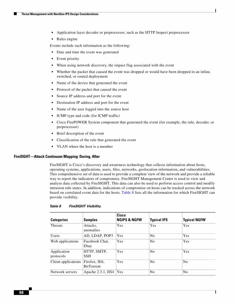
Threat Management with NextGen IPS Design Considerations
• Application layer decoder or preprocessor, such as the HTTP Inspect preprocessor
• Rules engine
Events include such information as the following:
• Date and time the event was generated
• Event priority
• When using network discovery, the impact flag associated with the event
• Whether the packet that caused the event was dropped or would have been dropped in an inline, switched, or routed deployment
• Name of the device that generated the event
• Protocol of the packet that caused the event
• Source IP address and port for the event
• Destination IP address and port for the event
• Name of the user logged into the source host
• ICMP type and code (for ICMP traffic)
• Cisco FirePOWER System component that generated the event (for example, the rule, decoder, or preprocessor)
• Brief description of the event
• Classification of the rule that generated the event
• VLAN where the host is a member
FireSIGHT—Attack Continuum Mapping: During, After
FireSIGHT is Cisco’s discovery and awareness technology that collects information about hosts, operating systems, applications, users, files, networks, geolocation information, and vulnerabilities. This comprehensive set of data is used to provide a complete view of the network and provide a reliable way to report the indicators of compromise. FireSIGHT Management Center is used to view and analyze data collected by FireSIGHT. This data can also be used to perform access control and modify intrusion rule states. In addition, indications of compromise on hosts can be tracked across the network based on correlated event data for the hosts. Table 8 lists all the information for which FireSIGHT can provide visibility.
Table 8 FireSIGHT Visibility
Categories SamplesCisco NGIPS & NGFW Typical IPS Typical NGFW
Threats Attacks, anomalies
Yes Yes Yes
Users AD, LDAP, POP3 Yes No Yes
Web applications Facebook Chat, Ebay
Yes No Yes
Application protocols
HTTP, SMTP, SSH
Yes No Yes
Client applications Firefox, IE6, BitTorrent
Yes No No
Network servers Apache 2.3.1, IIS4 Yes No No
58

Threat Management with NextGen IPS Design Considerations
Indicators of Compromise—Attack Continuum Mapping: During, After
The system can correlate certain types of intrusion, malware, and other events occurring on hosts on the network to determine when hosts are potentially compromised, tagging those hosts with indications of compromise (IOC) tags. IOC data can give a clear, direct picture of the threats of the monitored network as they relate to its hosts.
The system uses all of this information to help with forensic analysis, behavioral profiling, access control, and mitigating and responding to the vulnerabilities and exploits to which the organization is susceptible.
Dynamic File Analysis (Sandboxing)—Attack Continuum Mapping: During, After
For additional malware analysis and threat identification on files, eligible captured files can be submitted to the Sourcefire Cloud for dynamic analysis. The Cisco-Sourcefire cloud runs the file in a test environment, and based on the results, returns a threat score and dynamic analysis summary report to the FireSIGHT Management Center. Eligible files can also be submitted to the Cisco-Sourcefire cloud for Spero analysis, which examines the file’s structure to supplement the malware identification. Submitting a file to the cloud for dynamic analysis depends on the type of file captured, as well as the allowable minimum and maximum file sizes configured in the access control policy. Files can be submitted as follows:
• Automatically for dynamic analysis if a file rule performs a malware cloud lookup on an executable file and the file disposition is Unknown
• Up to twenty-five files at once manually for dynamic analysis if stored and a supported file type, such as PDFs, Microsoft Office documents, and others.
Once submitted, the files are queued for analysis in the cloud. The captured files and a file’s trajectory can be viewed to determine whether a file has been submitted for dynamic analysis. Each time a file is submitted for dynamic analysis, the cloud analyzes the file, even if the first analysis generated results. The cloud performs dynamic analysis by running the file in a sandbox environment. The cloud analysis returns the following:
• Threat score, which details the likelihood a file contains malware
• A dynamic analysis summary report, which details why the cloud assigned the threat score
Based on the file policy configuration, files whose threat score falls above a defined threshold can automatically be blocked. Further review of the dynamic analysis summary report can help better identify malware and fine-tune detection capabilities.
Operating systems Windows, Linux Yes No No
Routers and switches
Cisco, Nortel, Wireless
Yes No No
Wireless Access Points
Linksys, Netgear Yes No No
Mobile devices iPhone, Android Yes No No
Printers HP, Xerox, Canon Yes No No
VoIP phones Avaya, Polycom Yes No No
Virtual machines VMware, Xen Yes No No
Table 8 FireSIGHT Visibility (continued)
Categories SamplesCisco NGIPS & NGFW Typical IPS Typical NGFW
59

Threat Management with NextGen IPS Design Considerations
Connection Data—Attack Continuum Mapping: During, After
FirePOWER appliances continuously monitor traffic generated by the hosts on the network. The access control feature can be used to generate connection events when network traffic matches specific conditions. Connection events contain data about the detected sessions, including timestamps, IP addresses, geolocation, applications, and so on. Access control policies to log connection events when:
• Network traffic is blacklisted or monitored by Security Intelligence; this also creates Security Intelligence events
• Network traffic meets the conditions of a non-Monitor access control rule
• Network traffic is handled by an access control policy’s default action
• Network traffic meets the conditions of at least one Monitor rule (automatically enabled)
• An intrusion policy associated with an access control rule generates an event (automatically enabled)
• A file policy associated with an access control rule detects or blocks a file, or discovers or blocks malware (automatically enabled)
Tying connection logging to individual access control rules, policies, and configurations give granular control over the connections to be logged.
Connection Summaries—Attack Continuum Mapping: After
The Cisco FirePOWER System aggregates connection data collected over five-minute intervals into connection summaries, which the system uses to generate connection graphs and traffic profiles. Optionally, custom workflows based on connection summary data can be created, which are used in the same way as workflows based on individual connection events. There are no connection summaries specifically for Security Intelligence events, although corresponding end-of-connection events can be aggregated into connection summary data. To be aggregated, multiple connections must:
• Represent the end of connections
• Have the same source and destination IP addresses, and use the same port on the responder (destination) host
• Use the same protocol (TCP or UDP)
• Use the same application protocol
• Either be detected by the same FireSIGHT-managed device, or be exported by the same NetFlow-enabled device. Each connection summary includes total traffic statistics, as well as the number of connections in the summary.
Note that connection summaries do not contain all of the information associated with the summaries’ aggregated connections. For example, because client information is not used to aggregate connections into connection summaries, summaries do not contain client information.
Access Control and Segmentation
The Single Site Clustering with TrustSec in combination with the Secure Enclaves Architecture provides for an extensive set of Access Control and Segmentation Capabilities.
Access Control—Attack Continuum Mapping: Before, During
An access control policy determines how the system handles traffic on the network. One or more access control policies can be configured, which can then be applied to one or more FirePOWER appliances.
60

Threat Management with NextGen IPS Design Considerations
Each device can have one currently applied policy.
A simple access control policy can filter traffic based on Security Intelligence data, then use the policy’s default action to handle non-blacklisted traffic in one of the following ways:
• Block all traffic from entering the network
• Trust all traffic to enter the network without further inspection
• Allow all traffic to enter the network, and inspect the traffic with a Network Discovery Policy only
• Allow all traffic to enter the network, and inspect the traffic with Intrusion and Network Discovery Policies
Optionally, access control rules can be added to a policy, which provide granular control over how network traffic is handle and logged. For each rule, a rule action is specified as to whether to trust, monitor, block, or inspect matching traffic with an intrusion or file policy. Each rule contains a set of conditions that identify the specific traffic to control. Rules can be simple or complex, matching traffic by any combination of security zone, network, VLAN, source or destination country or continent, Active Directory LDAP user or group, application, transport protocol port, or URL.
Figure 42 illustrates traffic flow through the FirePOWER appliance and provides some details on the types of inspection performed on that traffic. Notice that the system does not inspect fastpathed or blacklisted traffic. For traffic handled by an access control rule or default action, flow and inspection depend on the rule action. Although rule actions are not shown in the diagram for simplicity, the system does not perform any kind of inspection on trusted or blocked traffic. Additionally, file inspection is not supported with the default action.
Figure 42 Access Control Policy Flow Diagram
HTTP Response Page—Attack Continuum Mapping: After
When an access control rule blocks a user’s HTTP request, what the user sees in a web browser depends on how the system is configured to block the session. When choosing a rule action, select:
• Block or Block with reset to deny the connection. A blocked session times out; the system resets Block with reset connections. For both blocking actions, the default browser or server page can be overridden with a custom page that explains that the connection was denied.
• Interactive Block or Interactive Block with reset to display an HTTP response page that warns users, but also allows them to click a button to continue or refresh the page to load the originally requested site.
IncomingPacket
Fast-PathRules
SecurityIntelligence
Traffic allowedIntrusion InspectionFile InspectionDiscovery
Traffic blockedIntrusion InspectionFile InspectionDiscovery
notfast-
pathed
fast-pathed
Traffic flow andinspection depend
on rule action
blacklisted
Traffic flow andinspection dependon default action
first non-Monitorrule matched
notblack-
listeded
AccessControl
Rules
Access Control Policy
matches norules or only
Monitor rules
Access ControlDefault Action
61

Threat Management with NextGen IPS Design Considerations
Notifying the end users of policy enforcement action can significantly reduce the frustration of users and administrators by providing an easy way to determine why traffic was blocked.
Note that HTTP response pages do not appear for traffic blocked because of a Security Intelligence blacklist or an application detected based on a Secure Sockets Layer (SSL) certificate.
Identity Management
When a FirePOWER appliance detects a login, it sends the following information to the FireSIGHT Management Center to be logged as user activity:
• User name identified in the login
• Time of the login
• IP address involved in the login
• User’s email address (for POP3, IMAP, and SMTP logins)
• Name of the device that detected the login. If the user was previously detected, the FireSIGHT Management Center updates that user’s login history.
FireSIGHT Management Center can use the email addresses in POP3 and IMAP logins to correlate with LDAP users. For example, if FireSIGHT Management Center detects a new IMAP login, and the email address in the IMAP login matches that for an existing LDAP user, the IMAP login does not create a new user; rather, it updates the LDAP user’s history. If the user has never been detected before, the FireSIGHT Management Center adds the user to the users database. Unique AIM, SIP, and Oracle logins always create new user records, because there is no data in those login events that the FireSIGHT Management Center can correlate with other login types.
The FireSIGHT Management Center does not log user activity or user identities in the following cases:
• If the network discovery policy is configured to ignore that login type
• If a managed device detects an SMTP login, but the users database does not contain a previously detected LDAP, POP3, or IMAP user with a matching email address
Cisco recommends that Sourcefire User Agents be installed onto any Microsoft Active Directory LDAP servers to monitor user activity via the Active Directory servers. To enable the user control capability, the Sourcefire User Agents must be installed so that users can be associated with IP addresses. This allows access control rules with user conditions to trigger.
One Sourcefire User Agent can be used to monitor user activity on up to five Active Directory servers. To use an agent, configure a connection between each FireSIGHT Management Center connected to the agent and the monitored LDAP servers. This connection not only allows retrieval of metadata for the users whose logins and logoffs were detected by User Agents, but also is used to specify the users and groups to use in access control rules.
From the LDAP server, the FireSIGHT Management Center obtains the following information and metadata about each user:
• LDAP user name
• First and last names
• Email address
• Department
• Telephone number
The User Activity Database contains records of user activity on the network, either from a connection to an Active Directory LDAP server that is also monitored by a Sourcefire User Agent, or though
62

Threat Management with NextGen IPS Design Considerations
network discovery. The system logs events in the following circumstances:
• When it detects individual logins or logoffs
• When it detects a new user
• When manually deleting a user
• When the system detects a user that is not in the database, but cannot add the user because the FireSIGHT licensed limit has been reached
Application Visibility and Control
Host Profiles—Attack Continuum Mapping: Before, During
A host profile provides a complete view of all the information the FireSIGHT Management system has gathered about a single host such as the MAC address, host name, and operating system. Host attributes are user-defined descriptions that can be applied to a host are also listed in the host profile. For example, a host attribute could be assigned that indicates the building where the host is located. From a host profile, you can view the existing host attributes applied to that host and can modify the host attribute values. Host profiles also provide information about the servers, clients, and host protocols running on a particular host, including whether they are in compliance with a compliance white list. Servers can be removed from the white list, and details viewed for those servers.
Additional information can be viewed such as connection events for servers, log information about the session where server traffic was detected as well as connection events for clients, and deleted servers, clients, or host protocols from the host profile. User history information for a host can be viewed if the system has been configured to track it. The host profile provides a list of vulnerabilities that can be modified, and this capability provides information on which vulnerabilities have been addressed for the host.
File Control—Attack Continuum Mapping: Before, During
File control allows managed devices to detect and block users from uploading (sending) or downloading (receiving) files of specific types over specific application protocols. File control can be configured as part of the overall access control configuration with file policies that are associated with access control rules. A file policy is a set of configurations that the system uses to perform advanced malware protection and file control, as part of the overall access control configuration. Figure 43 shows a simple access control policy in an inline deployment.
63

Threat Management with NextGen IPS Design Considerations
Figure 43 Simple Access Control Policy
A file policy, like its parent access control policy, contains rules that determine how the system handles files that match the conditions of each rule. Separate file rules can be configured to take different actions for different file types, application protocols, or directions of transfer. Once a file matches a rule, the rule can:
• Allow or block files based on simple file type matching
• Block files based on malware file disposition
• Store captured files to the device
• Submit captured files for dynamic analysis
In addition, the file policy can:
• Automatically treat a file as if it is clean or malware based on entries in the clean list or custom detection list
• Treat a file as if it is malware if the file’s threat score exceeds a configurable threshold
Table 9 lists the file rule components.
Rule 1: Allow
network traffic
matchingtraffic
matchingtraffic
files allowed/blockedper File Policy A
traffic allowed withoutfile inspection
Access Control Policy
Rule 2: Allow
File Policy A
files allowed/blockedper File Policy A
Default Action:Allow
File Policy B
no match
no match
3479
59
Table 9 File Rule Components
File Rule Component DescriptionApplication protocol
The system can detect and inspect files transmitted via FTP, HTTP, SMTP, IMAP, POP3, and NetBIOS-ssn (SMB).
Direction of Transfer
The system can inspect incoming FTP, HTTP, IMAP, POP3, and NetBIOS-ssn (SMB) traffic for downloaded files. As well as inspect outgoing FTP, HTTP, SMTP, and NetBIOS-ssn (SMB) traffic for uploaded files.
File categories and types
The system can detect various types of files that are grouped into basic categories such as multimedia (swf, mp3), executables (exe, torrent), and PDFs.
File rule action A file rule’s action determines how the system handles traffic that matches the conditions of the rule. File rules are evaluated in rule-action, not numerical, order.
64

Threat Management with NextGen IPS Design Considerations
SSL Application Detection—Attack Continuum Mapping: During
The FirePOWER System provides detectors that can use session information from a Secure Socket Layers (SSL) session to identify the application protocol, client application, or web application in the session.
When the system detects an encrypted connection, it marks that connection as either a generic HTTPS connection or as a more specific secure protocol, such as SMTPS. When the system detects an SSL session, it adds SSL client to the client field in connection events for the session. If it identifies a web application for the session, the system generates discovery events for the traffic.
For SSL application traffic, managed devices running Version 5.2 or later can also detect the common name from the server certificate and match that against a client or web application from an SSL host pattern. When the system identifies a specific client, it replaces SSL client with the name of the client. Because the SSL application traffic is encrypted, the system can use only information in the certificate for identification and not the application data within the encrypted stream. For this reason, SSL host patterns can sometimes identify only the company that authored the application, so SSL applications produced by the same company may have the same identification.
Network File Trajectory—Attack Continuum Mapping: During, After
The network file trajectory feature uses SHA-256 hash values to track a file’s transmission path across a network.
To track a file transmission across the network, the system must either:
• Calculate the file’s SHA-256 hash value and perform a malware cloud lookup using that value
• Receive endpoint-based threat and quarantine data about that file, using the FireSIGHT Management Center’s integration with the organization’s FireAMP subscription
Each file has an associated trajectory map, which contains a visual display of the file’s transfers over time as well as additional information about the file.
Application Detection—Attack Continuum Mapping: During, After
When the FireSIGHT Management System analyzes IP traffic, it attempts to identify the commonly used applications on the network. Application awareness is crucial to performing application-based access control. There are three types of applications that the system detects:
• Application protocols such as HTTP and SSH
• Clients such as web browsers and email clients
• Web applications such as MPEG video and Facebook
The system identifies applications in network traffic flows either using ASCII or hexadecimal patterns in the packet headers, or the port that the traffic uses. Some application detectors use both port and pattern detection to increase the likelihood of correctly identifying traffic for a particular application.
There are two sources of application detectors in the FireSIGHT System:
• Sourcefire-provided detectors, which detect web applications, clients, and application protocols
• User-defined application protocol detectors, which can be created to enhance the system’s application protocol detection capabilities
Application protocols can also be detected through implied application protocol detection, which implies the existence of an application protocol based on the detection of a client. The FireSIGHT Management system uses a set of characteristics to create application filters that can be used to create to perform access control, as well as to constrain searches, reports, and dashboard widgets.
65

Threat Management with NextGen IPS Design Considerations
Detecting Sensitive Data—Attack Continuum Mapping: During, After
Sensitive data such as Social Security numbers, credit card numbers, driver’s license numbers, and so on may be leaked onto the Internet, intentionally or accidentally. The system provides a sensitive data preprocessor that can detect and generate events on sensitive data in ASCII text, which can be particularly useful in detecting accidental data leaks.
The system does not detect encrypted or obfuscated sensitive data, or sensitive data in a compressed or encoded format such as a Base64-encoded email attachment. The system detects sensitive data per TCP session by matching individual data types against traffic. Default settings can be modified for each data type and for global options that apply to all data types in the intrusion policy. The FireSIGHT Management System provides predefined, commonly used data types as well as allows the creation of custom data types. A sensitive data preprocessor rule is associated with each data type. Sensitive data detection and event generation can be enabled for each data type by enabling the corresponding preprocessor rule for the data type. Because the system uses TCP stream preprocessing to establish monitored sessions, TCP stream preprocessing must be enabled to use sensitive data detection in the policy.
Note Sensitive data detection can have a high impact on performance. Additional guidance on deploying this feature can be found in the Sourcefire FirePOWER System User Guide.
Logging and Traceability Management
Enabling Access to the Database
The FireSIGHT Management Center can be configured to allow read-only access to the database to a third-party client or applications. Note that when connecting to the database from an external client, a username and password that match those for an administrator or external database user on the FireSIGHT Management Center must be used.
Configuring Database Event Limits
To improve performance, the maximum number of each type of events that can be stored should be configured. Use the Database page to specify the maximum number of each type of event that the FireSIGHT Management Center can store. If the number of events in the intrusion event database exceeds the maximum, the oldest events and packet files are pruned until the database is back within the event limits. The discovery and user databases can be manually pruned as well. In addition, email address can be configured that will receive notifications when intrusion events and audit records are pruned from the database. Table 10 lists the minimum and maximum number of records that can be stored for each event type.
66

Threat Management with NextGen IPS Design Considerations
System Audit Logs
The appliances that are part of the FirePOWER System generate an audit record for each user interaction with the web interface, and also record system status messages in the system log.
FireSIGHT Management appliances and managed FirePOWER appliances also provide full reporting
Table 10 Database Event Limits
Event Type Upper Event Limit Lower Event LimitIntrusion events 2.5 million (DC500)
10 million (DC1000, virtual FireSIGHT Management Center) 20 million (DC750) 30 million (DC1500) 100 million (DC3000) 150 million (DC3500)
10,000
Discovery events 10 million zero (disables storage)
Connection events/ Security Intelligence events
10 million (DC500, DC1000, virtual FireSIGHT Management Center) 50 million (DC750) 100 million (DC1500, DC3000) 500 million (DC3500) Upper event limit is shared between connection events and Security Intelligence events; the sum of configured maximums for the two events cannot exceed the upper event limit.
zero (disables storage)
Connection summaries/ (Aggregated connection events)
10 million (DC500, DC1000, virtual FireSIGHT Management Center) 50 million (DC750) 100 million (DC1500, DC3000) 500 million (DC3500)
zero (disables storage)
Correlation and compliance whitelist events
1 million one
Malware events 10 million 10,000
File events 10 million zero (disables storage)
Health events 1 million zero (disables storage)
Audit records 100,000 one
Remediation status events
10 million one
Whitelist violation history of the hosts on your network
30-day history of violations one day’s history
User activity (user events)
10 million one
User logins (user history)
10 million one
Rule update import log records
1 million one
67

Validation Results
features that allow reports to be generated for almost any type of data accessible in an event view, including auditing data. The audit log stores a maximum of 100,000 entries. When the number of audit log entries exceeds 100,000, the appliance prunes the oldest records from the database to reduce the number to 100,000.
Streaming Audit Log
A system policy can be configured so that the appliance streams an audit log to an external host. It is important that the external host is functional and accessible from the appliance sending the audit log. Note that if the computer that is configured to receive an audit log is not set up to accept remote messages, the host will not accept the audit log.
System Log
The System Log (syslog) page provides system log information for the appliance. The system log displays each message generated by the system, which are listed in the following order:
• Date that the message was generated
• Time that the message was generated
• Host that generated the message
• The message itself
Note System log information is local. For example, FireSIGHT Management Center cannot be used to view system status messages in the system logs on the FirePOWER appliances. System log messages can be viewed for specific components by using the filter feature.
NetFlow
For the networks specified, the FirePOWER appliances detect the records exported by NetFlow-enabled devices, generate connection events based on the data in those records, and finally send those events to the FireSIGHT Management Center to be logged in the database.
The Secure Data Center for the Enterprise includes the Cyber Threat Defense for the Data Center Cisco Validated Design, which is a Lancope Stealthwatch-based solution that is optimized for NetFlow-based threat analysis. Additional recommendations for using NetFlow with the FireSIGHT Management and FirePOWER appliances are out of scope of this design guide.
Validation ResultsThis solution has been validated for each of the various deployment options as described in this document. Each deployment option will be discussed in separate implementation guides with validation result details included.
SummaryData Center Operation Teams have a cyber security challenge facing them unlike any other in the history of IT. The cyber attacker community has spent years developing their capabilities to be able to breach any network and any device at any time. The Secure Data Center: Threat Management with
68

References
NextGen IPS is part of a larger solution portfolio that is focused on giving the cyber defenders a full set of capabilities to protect their data centers while still being operationally efficient for scalability.
References • Secure Data Center for the Enterprise: Single Site Clustering with TrustSec—
http://www.cisco.com/en/US/solutions/collateral/ns340/ns414/ns742/ns744/docs/sdc-dg.pdf
• Secure Data Center for the Enterprise: Secure Enclaves Architecture
• Secure Data Center for the Enterprise: Cyber Threat Defense for the Data Center— http://www.cisco.com/c/dam/en/us/solutions/collateral/enterprise/design-zone-secure-data-center-portfolio/sea_ctd.pdf
• Sourcefire 3D System User Guide 60
• Sourcefire 3D System Installation Guide
• Cisco Nexus 7000 Series NX-OS System Management Configuration Guide— http://www.cisco.com/c/en/us/td/docs/switches/datacenter/sw/5_x/nx-os/system_management/configuration/guide/sm_nx_os_cg.pdf
• NIST Special Publication 800-53 Revision 4, “Security and Privacy Controls for Federal Information Systems and Organizations”— http://www.nist.gov/manuscript-publication-search.cfm?pub_id=915447
• “Subvirt: Implementing Malware with Virtual Machines” Presentation, Samuel T. King, Peter M. Chen, University of Michigan— http://www.cse.psu.edu/~mcdaniel/cse544/slides/cse544-subvirt-sawani.pdf
• “Top 20 Critical Security Controls - Version 5”, SANS Institute— http://www.sans.org/critical-security-controls/
• “Find, Fix, Track, Target, Engage, Assess”, John A. Tirpak— www.airforcemag.com/magazinearchive/pages/2000/july%202000/0700find.aspx
69

References
70