section iii sanitary sewer systems - slwsd.com · sanitary sewer systems ... and sewers. x ground...
TRANSCRIPT
SECTION III
SANITARY SEWER SYSTEMS
SANITARY SEWER SYSTEMS
TABLE OF CONTENTS
Page
1. Objective ............................................................................................................. 12. General ................................................................................................................ 13. General Requirements .......................................................................................... 34. Materials .............................................................................................................. 55. Side Sewer Lateral ............................................................................................. 106. Testing Gravity Sewers for Acceptance.............................................................. 117. Televised Inspection .......................................................................................... 138. Adjustment of New and Existing Utility Structures to Grade .............................. 159. Final Acceptance ............................................................................................... 1710. Private Side Sewers ........................................................................................... 17
(4/2017) III-1
III. SANITARY SEWER SYSTEMS - GENERAL STANDARDS 1. OBJECTIVE:
Section III is intended to present information and provide an outline of the minimum general standards required by Silver Lake Water & Sewer District for Developer constructed sanitary sewerline facilities and improvements which are to be acquired and operated by the District.
2. GENERAL:
Detailed plans shall be submitted for the District’s review, which provide the location, size, type and direction of flow of the proposed sewers and the connection with existing sewers. These plans shall be separate from Water Plans and shall conform to District Drafting Standards. All sewer system design submittals with drainage basins serving to Alderwood Water and Wastewater District for conveyance to King County facilities requires King County design review and acceptance prior to acceptance by Silver Lake Water & Sewer District.
Project plans should have a horizontal scale of 1 inch = 50 feet and a vertical scale of 1 inch = 5 feet. Plan and profile views for any give section of gravity sewer or force main shall be drawn on the same sheet. Plans and profiles shall show:
Locations of streets, right-of-ways, existing utilities, and sewers.
Ground surface, pipe type, class and size, manhole stationing, invert and surface elevation at each manhole, and grade of sewer between adjacent manholes. Elevations shall be based on the NAVD 88 datum, with a conversion factor to the NGVD 29 datum noted on the plans, as further described in the General Drafting Standards. All manholes shall be numbered on the plans and correspondingly numbered on the profile. Where there is any question of the sewer being sufficiently deep to serve any residence, the elevation and location of the basement floor, if basements are served, shall be plotted on the profile of the sewer that is to serve the house in question. The Developer shall state that all sewers are sufficiently deep to serve adjacent basements, except where otherwise noted on the plans.
All known existing structures, both above and below ground, which might interfere with the proposed construction, particularly water mains, gas mains, storm drains, overhead and underground power lines, telephones lines, and television cables.
III. SANITARY SEWER SYSTEMS - GENERAL STANDARDS - Continued
(4/2017) III-2
All utility easements.
District Approval Block
Details in scale drawings, which clearly show special sewer joints and cross-sections, and sewer appurtenances such as manholes and related items.
Construction of new sewer systems or extensions of existing systems will be allowed only if the existing receiving system is capable of supporting the added hydraulic load. Collection and interceptor sewers shall be designed for the ultimate development of the tributary areas. Sewer systems shall be designed and constructed to achieve total containment of sanitary wastes and maximum exclusion of infiltration and inflow. Computations and other data used for design of the sewer system shall be submitted to the District for approval. The sewage facilities shall be constructed in conformance with the current WSDOT Standard Specifications for Road, Bridge, & Municipal Construction, and current amendments thereto, revised as to form to make reference to Local Governments, and as modified by the District’s requirements and standards. Material and installation specifications shall contain appropriate requirements that have been established by the industry in its technical publications, such as ASTM, AWWA, WEF, and APWA standards. Requirements shall be set forth in the specifications for the pipe and methods of bedding and backfilling so as not to damage the pipe or its joints, impede cleaning operations and future tapping, nor create excessive side fill pressure or deformation of the pipe, nor seriously impair flow capacity. All sewers shall be designed to prevent damage from superimposed loads. Proper allowance for loads on the sewer because of the width and depth of trench should be made. When standard-strength sewer pipe is not sufficient, extra-strength pipe shall be used. After all other work is completed and before final acceptance, the entire roadway, including the roadbed, planting, sidewalk areas, shoulders, driveways, alley and side street approaches, slopes, ditches, utility trenches, and construction areas shall be neatly finished to the lines, grades and cross sections for a new roadway consistent with the original section.
III. SANITARY SEWER SYSTEMS - GENERAL STANDARDS - Continued
(4/2017) III-3
3. GENERAL REQUIREMENTS:
1. Prior to construction, the sewer plans shall be reviewed and approved by the Department of Ecology with an affidavit stating such on file at the District’s office, unless the review and approval is waived by Ecology.
2. Work shall be performed only by contractors experienced in laying public
sewer mains. 3. Prior to any work being performed, the Developer shall contact the
District’s Engineer to set forth his proposed schedule. 4. All materials shall be new and undamaged.
5. Developer shall obtain approval of materials to be used from the District
prior to ordering of materials. 6. Sewer mains shall be laid only in dedicated streets or in easements that
have been granted to the District. A street is normally not considered until the plat, which created it, has been filed with the County Auditor.
7. All service connections to the District sewer system shall be a gravity
connection. If service lines to structures or lots to be served are over 200 feet (not including panhandle), the Developer shall install an 8-inch sewer main within 100 feet of the farthest lot with a manhole at the end in an easement granted to the District. Parallel side sewers shall be separated by a minimum of 5 feet horizontally from each sewer service and 10 feet from parallel water services.
8. The sewer mains shall run parallel to and 5 feet southerly or westerly of
street centerline where possible. The sewer main shall maintain a minimum 10-foot horizontal separation from proposed or existing water mains.
9. The minimum slope for 8-inch gravity mains shall be 0.5 percent (except
the minimum slope for dead end runs shall be 1.0 percent for 8-inch gravity mains). The minimum slope for 6-inch side sewer laterals shall be 2.0 percent and the maximum shall be 100 percent (45°).
10. The maximum distance between manholes shall be 400 feet unless
approved by the District. 11. Manholes shall be a minimum of 8-feet deep unless approved by the
District.
III. SANITARY SEWER SYSTEMS - GENERAL STANDARDS - Continued
(4/2017) III-4
12. Manholes greater than 20-feet deep shall be a minimum of 54-inches inside diameter.
13. Manholes greater than 25-feet deep should not be submitted for review
without prior approval of deep design concept by the District. Deep designs will not be approved if alternative service can be provided with shallower gravity service, even if the property developing will have to delay development.
14. Manholes shall be provided with a 0.10-foot drop across the channel.
15. Terminating manholes, where sewer extension may occur, shall be
channeled accordingly. 16. Locking lids shall be provided for all manholes and all manhole lids shall
have the word “sewer” cast integrally onto its surface.
17. All manholes shall be accessible to maintenance vehicles.
18. Manholes in easements shall be provided with a green fiberglass locator marker post with the footage to the manhole stenciled on with 2-inch letters.
19. All side sewer laterals shall be of the same material as the main line unless
approved by the District.
20. Front lot corners and a property line stake shall be staked prior to construction for side sewer tee location.
21. Side sewers are normally extended to the lowest property corner and
located a minimum of 10 feet from the side lot line and are extended past dry utilities unless prior approval from District for alternate location.
22. Side sewer connections allowed directly into manholes shall be
constructed to match the sewer main crown and the manhole channeled accordingly.
23. All commercial, industrial or school food establishments shall be equipped
with an approved grease interceptor located outside the building, as required by the District, prior to discharging to the sewer main. Sizing to be confirmed by a Professional Engineer licensed in the State of Washington.
24. Provide the District a copy of the cut sheets prior to construction.
III. SANITARY SEWER SYSTEMS - GENERAL STANDARDS - Continued
(4/2017) III-5
25. Pipe trenches shall not be backfilled until pipe and bedding installation has been inspected by the District.
26. Final air testing shall not be accepted until all underground utilities have
been installed, compaction is completed, and the lines have been flushed, cleaned, deflection tested and television inspected.
27. Road restoration shall be per Snohomish County, City and/or State design
and construction standards. The Developer shall become familiar with all County, City and State conditions of required permits, and shall adhere to all conditions and requirements.
28. Manhole rim, sewer location, and invert elevations shall be field verified
after construction by the Developer’s engineer(s) and the “as constructed” drawings individually stamped by a Professional Engineer licensed in the State of Washington which shall attest to the fact that the information is correct.
4. MATERIALS:
SEWER MAINS AND LATERALS (See sewage lift station Section IV for force mains.) Sewer mains to be installed shall be of material noted below:
Purpose Material Cover Max. Slope Gravity Sewer & Laterals PVC 5'-18' 18% Ductile Iron 3' - 5' -- Ductile Iron 18' --
PVC AWWA C900 Class 200 18' 18%
Force Mains Ductile Iron 4' --
PVC pipe shall be a minimum Class S.D.R. 35 and be manufactured in accordance with ASTM D3034. The pipe and fittings shall be furnished with bells and spigots, which are integral with the pipe wall. Pipe and fittings shall be of the same material. Pipe joints shall use flexible elastomeric gaskets conforming to ASTM D3212. Nominal laying lengths shall be 20 feet and 13 feet. PVC C900 pipe shall conform to AWWA C900 and will be allowed in deep trench construction at the discretion of the District.
The ductile iron pipe shall conform to AWWA C151 and shall be Class 52. Pipe and fittings shall be of the same material. Grade of iron shall be a minimum of 60-42-10. The pipe shall be polyethylene or epoxy lined to a nominal thickness of 40 mils. Minimum lining thickness shall be 30 mils. Products meeting the
III. SANITARY SEWER SYSTEMS - GENERAL STANDARDS - Continued
(4/2017) III-6
standard are US Pipe “Polylined,” “Protecto 401,” and American Pipe “Polyband,” or equal. The exterior shall be coated with an asphaltic coating.
Each length shall be plainly marked with the manufacturer’s identification, year cast, thickness, class of pipe and weight. The pipe shall be furnished with mechanical joint or push-on type joint, except where plans call for flanged ends. Joints shall conform to AWWA C111. Restrained joint pipe shall be push-on joint pipe with FIELD LOK® or TR FLEX® gaskets as furnished by U.S. Pipe. All pipe shall be jointed by the manufacturer’s standard coupling, be all of one manufacturer, be carefully installed in complete compliance with the manufacturer’s recommendations. All fittings shall be short-bodied, ductile iron complying with AWWA C110 or C153 for 350 psi pressure rated mechanical joint fittings and 250 psi pressure rated flanged fittings. All fittings shall be polyethylene or epoxy lined per the ductile iron pipe specifications and either mechanical joint or flanged, as indicated on the Plans.
Fittings in areas requiring restrained joints shall be mechanical joint fittings with a mechanical joint restraint device. The mechanical joint restraint device shall have a working pressure of at least 250 psi with a minimum safety factor of 2:1 and shall be EBAA Iron, Inc., MEGALUG, or approved equal.
All couplings shall be ductile iron mechanical joint sleeves.
The sewer pipe, unless otherwise approved by the District shall be laid upgrade from point of connection on the existing sewer or from a designated starting point. The sewer pipe shall be installed with the bell end forward or upgrade. When pipe laying is not in progress, the forward end of the pipe shall be kept tightly closed with an approved temporary plug. Wherever movable shoring (steel box) is used in the ditch, pipe shall be restrained by use of a winch mounted in the downstream manhole and a line of sufficient strength threaded through the pipe and set tight before each move. Any indication that joints are not being held shall be sufficient reason for the District to require restraints, whether or not movable shoring is being used.
All gravity pipe shall be laid in straight lines and at uniform rate of grade between manholes. Variance from established line and grade shall not be greater than 1/2 inch, provided that such variation does not result in a level or reverse sloping invert; provided, also, that variation in the invert elevation between adjoining ends of pipe, due to non-concentricity of joining surface and pipe interior surfaces, does not exceed 1/64 of an inch per inch of pipe diameter, or 1/2-inch
III. SANITARY SEWER SYSTEMS - GENERAL STANDARDS - Continued
(4/2017) III-7
maximum. Any corrections required in line and grade shall be reviewed with the District and shall be made at the expense of the Developer.
All extensions, additions and revisions to the sewer system, unless otherwise indicated, shall be made with sewer pipe jointed by means of a flexible gasket, which shall be fabricated and installed in accordance with the manufacturer’s specifications. All joints shall be made up in strict compliance with the manufacturer’s recommendations and all sewer pipe manufacture and handling shall meet or exceed the ASTM recommended specifications. Pipe handling after the gasket has been affixed shall be carefully controlled to avoid disturbing the gasket and knocking it out of position, or loading it with dirt or other foreign material. Any gaskets so disturbed shall be removed, cleaned, relubricated if required, and replaced before the rejoining is attempted. Care shall be taken to properly align the pipe before joints are entirely forced home. During insertion of the tongue or spigot, the pipe shall be partially supported by hand, sling or crane to minimize unequal lateral pressure on the gasket and to maintain concentricity until the gasket is properly positioned. Since most flexible gasketed joints tend to creep apart when the end pipe is deflected and straightened, such movement shall be held to a minimum once the joint is home. Sufficient pressure shall be applied in making the joint to assure that it is home, as described in the installation instructions provided by the pipe manufacturer. Sufficient restraint shall be applied to the line to assure that joints once home are held so, until fill material under and alongside the pipe has been sufficiently compacted. At the end of the work day, the last pipe laid shall be blocked in an effective way to prevent creep during “down time.” For the joining of dissimilar pipes suitable adapter couplings shall be used which have been approved by the District.
All gravity sewer pipe shall be bedded with pea gravel. The PVC pipe shall be bedded from a depth of 4-inches below the pipe to 12 inches above the pipe and ductile iron gravity sewer pipe shall be bedded from a depth of 4 inches below the pipe to the springline of the pipe. The bedding material shall extend across the full width of the trench and shall be compacted under the haunches of the pipe.
Special concrete bedding shall consist of a pipe cradle constructed of Portland cement concrete containing not less than four sacks of cement per cubic yard. Sand, gravel and water proportions are subject to approval by the District. Maximum aggregate size shall be 1-1/2 inches. Maximum slump shall be 4 inches. The bottom of the trench shall be fully compacted before the placement
III. SANITARY SEWER SYSTEMS - GENERAL STANDARDS - Continued
(4/2017) III-8
of pipe cradle. The Developer shall protect pipe against flotation and disturbing the horizontal alignment of the pipe during the pouring of the concrete.
Clay or Bentonite dams shall be installed across the trench and to the full depth of the granular material in all areas of steep slopes, stream crossings and wetland to prevent migration of water along the pipeline.
All backfill in roadway sections shall be placed and compacted in accordance with Snohomish County, City and/or State requirements and copies of the compaction results shall be provided to the District. All backfill in easements shall be placed and compacted to a minimum of 90 percent of the Modified Proctor dry maximum density per ASTM D1557. Copies of compaction results for all sewer system trenches shall be provided to the District. Recycled concrete is not allowed for use in District trench sections, no exceptions.
MANHOLES:
Manholes shall be of the offset type and shall be precast concrete sections with either a cast in place base, or a precast base made from a 3,000 psi structural concrete. Joints between precast wall sections shall be confined O-ring or as otherwise specified. The minimum diameter for manholes shall be 48 inches to a depth of 20 feet, and 54 inches for depths of 20 feet and greater. The District may require the diameter to be increased beyond the minimum based on future needs. For connections to existing systems, a concrete coring machine, suitable for this type of work, shall be utilized in making the connection. The existing manhole shall be rechanneled as required. The new pipe connection shall be plugged (water tight) until the new pipe system has been installed and approved. The Developer shall be responsible for any existing defects in the existing manhole unless these defects are witnessed by a representative of the District prior to any work being performed to make the connection. The Contractor shall be required to remove any and all deleterious material in the existing manhole and downstream reaches as a result of this work. Manholes located in easements or outside of paved areas shall have concrete collars with a minimum size of 48 inches diameter by 12 inches thick and marked with a green carsonite marker.
Manhole Sections
Manhole sections shall be placed and aligned so as to provide vertical sides and vertical alignment of the ladder steps. The completed manhole shall be rigid, true to dimension, and be water tight. Rough, uneven surfaces will not be permitted.
III. SANITARY SEWER SYSTEMS - GENERAL STANDARDS - Continued
(4/2017) III-9
Manhole Steps and Ladders Manhole steps shall be polypropylene, Lane International Corp. No. P13938 or equal. Ladders shall be polypropylene Lane International Corp. or equal, and shall be compatible with steps.
Grade Adjustment The manhole shall be set to provide not less than 14-inches or more than 26 inches of adjustment between the top of the cone or slab and the top of the manhole frame.
Masonry units (manhole adjusting rings) shall conform to the ASTM C2, Grade MA. The outside and inside of manhole adjusting rings and the joints of precast concrete sections shall be plastered and troweled smooth with 1/2 inch (minimum) of mortar in order to attain a watertight surface. No wood shall be used for adjustment.
Channels Channels shall be made to conform accurately to the sewer grade and shall be brought together smoothly with well rounded junctions, satisfactory to the District. The channels shall be field poured with concrete, no other fillers are permitted, after the inlet and outlet pipes have been laid and firmly grouted into place at the proper elevation. Allowances shall be made for a 0.1-foot drop in elevation across the manhole in the direction of flow. Channel sides shall be carried up vertically from the invert to three-quarters of the diameter of the various pipes. The concrete shelf shall be warped evenly and sloped 3/8 inch per foot to drain. Rough, uneven surfaces will not be permitted. Channels shall be constructed to allow the installation and use of a mechanical plug or flow meter of the appropriate size.
Drop Manholes Drop manholes on new construction require District approval and shall be constructed with outside drop(s). Approval will be limited to future extensions from deep sewers. Where extension from deep sewers is concurrent with deep sewer construction, drop manholes will not be allowed. Drop manholes shall, in all respects, be constructed as a standard manhole with the exception of the drop connection. Connection to existing District sewers may be allowed to use inside drop with prior District approval.
III. SANITARY SEWER SYSTEMS - GENERAL STANDARDS - Continued
(4/2017) III-10
Lift Holes and Steel Loops All lift holes shall be completely filled with expanding mortar, smoothed both inside and outside, to insure water tightness. All steel loops shall be removed, flush with the manhole wall. The stubs shall be covered with mortar and smoothed. Rough, uneven surfaces will not be permitted.
Frames and Covers Frames shall be cast iron and covers shall be ductile iron. Castings shall be free of porosity, shrink cavities, cold shuts or cracks, or any surface defects, which would impair serviceability. Repair of defects by welding, or by the use of “smooth-on” or similar material, will not be permitted. Frames and covers shall be machine finished or ground on seating surfaces so as to assure non-rocking fit in any position and interchangeability of covers. Frames and covers shall be provided with three bolt locking lids. Rings and covers shall be positioned so one of the three locking bolts is located over the manhole steps and shall be adjusted to conform to the final finished surface grade of the street or easement to the satisfaction of the District. Manhole frames and covers shall be as manufactured by East Jordan Iron Works Model 00371564, or equal. Must meet the (AASHTO) M306 specification and have replaceable lock down nuts.
Manhole Marker Posts A fiberglass manhole marker post shall be located adjacent to all manholes located in easement areas. The marker post shall be green in color, 3.75 inches wide (flat), 60-inches long and furnished with a 3-inch by 3-inch high intensity white reflector (250 Candle Power) and a flexible anchor barb. Each post shall include the following decal: “Caution Sewer Manhole. Before digging, Call 1-800-424-5555, Utility Underground Location Center.” Manhole markers shall be Carsonite Utility Marker CUM 375. The marker posts shall be set so as to leave 36 inches of the post exposed above grade. Distance from the marker to the manhole shall be stenciled on the marker with 2-inch letters.
5. SIDE SEWER LATERAL:
A side sewer lateral is considered to be that portion of a sewer line that will be constructed between a main sewer line and a property line or easement limit line. All applicable specifications given herein for sewer construction shall be held to apply to side sewer laterals.
III. SANITARY SEWER SYSTEMS - GENERAL STANDARDS - Continued
(4/2017) III-11
Side sewers shall be for a single connection only and be a minimum 6-inch-diameter pipe. Side sewers shall be connected to the tee, provided in the sewer main where such is available, utilizing approved fittings or adapters. The side sewer shall rise at a maximum of 45 degrees and a minimum of 2 percent, from the sewer main. Where there are no basements, the minimum side sewer depth shall be 6 feet below existing curb line and 5 feet below ground at the property line, except where existing improvements, proposed improvements or topography may dictate additional depth. The elevations of the side sewer connections shall be of sufficient depth to serve all existing and potential future basements.
Each 6-inch side sewer service shall be provided with a 12-foot-long 2 x 4 wooden post, which extends from the invert of the end of the 6 inch pipe to above the existing ground. The exposed area of this post shall be painted white and shall have stenciled thereon in 2 inch letters (black paint) “SEWER” and shall also indicate the total length of the 2 x 4. A 12-gauge (minimum) wire shall be wrapped around and stapled the full length of the 2 x 4. Where no tee or wye is provided or available, connection shall be made by machine-made tap and saddle. Inserta Tee, Fowler Manufacturing Company or approved equal may be utilized on concrete pipe only. Romac Style “CB” Sewer Saddle shall be utilized on PVC pipe. The maximum bend permissible at any one fitting shall not exceed 45 degrees. The maximum bend of any combination of two adjacent fittings shall not exceed 45 degrees (one-eighth bend) unless straight pipe of not less than 3 feet in length is installed between such adjacent fittings, or unless one of the fittings is a wye branch with a cleanout provided on the straight leg. Standing side sewers shall be constructed only with pre-approval of the District. Standing side sewers may be required, or allowed, at the sole discretion of the District. When allowed, standing side sewer tees will be constructed of the same material as the main line sewer.
6. TESTING GRAVITY SEWERS FOR ACCEPTANCE:
The Developer shall furnish all facilities and personnel for conducting tests. Methods other than Low Pressure Air Test shall be subject to the approval of the District. Pressure gauge to be oil filled to 0 to 30 psi read range.
Preparation for Testing for Leakage The Developer shall be required, prior to testing, to clean and flush all gravity sewer lines. The completed gravity sewer, including side sewer stubs, after completion of backfill and cleaning shall be televised. This will be permitted
III. SANITARY SEWER SYSTEMS - GENERAL STANDARDS - Continued
(4/2017) III-12
prior to paving. The sewer shall then be tested by the low pressure air test method and/or an infiltration test. Except, however, that in certain conditions an exfiltration test may be required by the District. The first section of pipe not less than 300 feet in length installed by each crew shall be tested, in order to qualify the crew and/or the material. A successful installation of this first section shall be a prerequisite to further pipe installation by the crew. At the Developer’s option, crew and/or material qualification testing may be performed at any time during the construction process after at least 2 feet of backfill has been placed over the pipe. Low Pressure Air Test The sewer pipe shall be tested for leaks through the use of air (unless exfiltration test is approved) in the following manner: Following the pipe cleaning, utility installation, and paving, the pipe installation shall be tested with low pressure air. Air shall be slowly supplied to the plugged pipe installation until the internal air pressure reaches 4.0 pounds per square inch greater than the average back pressure of any ground water that may submerge the pipe. 0.4 pounds per square inch to be added per 1 foot of water table over the pipe to a max. of 6 psi. At least 2 minutes shall be allowed for temperature stabilization before proceeding further. The rate of air loss shall then be determined by measuring the time interval required for the internal pressure to decrease from 3.5 to 2.5 pounds per square inch while maintaining the stipulated pressure greater than the pipe section’s average adjacent groundwater back pressure.
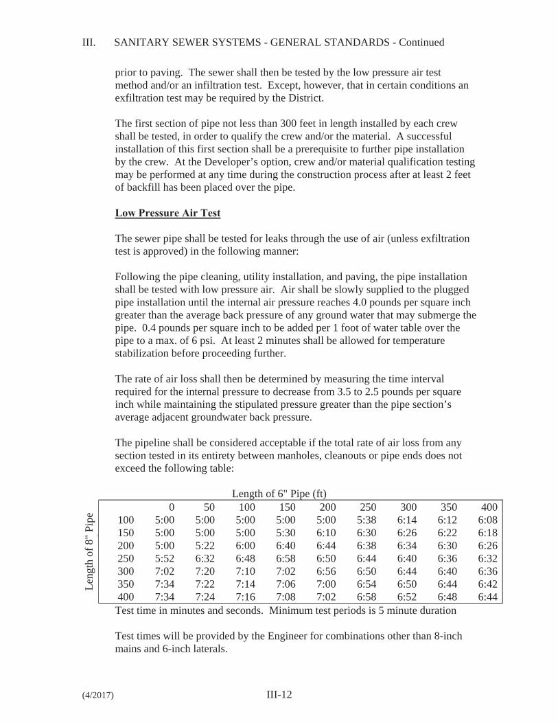
The pipeline shall be considered acceptable if the total rate of air loss from any section tested in its entirety between manholes, cleanouts or pipe ends does not exceed the following table:
Length of 6" Pipe (ft)
Leng
th o
f 8"
Pipe
(f
)
0 50 100 150 200 250 300 350 400100 5:00 5:00 5:00 5:00 5:00 5:38 6:14 6:12 6:08150 5:00 5:00 5:00 5:30 6:10 6:30 6:26 6:22 6:18200 5:00 5:22 6:00 6:40 6:44 6:38 6:34 6:30 6:26250 5:52 6:32 6:48 6:58 6:50 6:44 6:40 6:36 6:32300 7:02 7:20 7:10 7:02 6:56 6:50 6:44 6:40 6:36350 7:34 7:22 7:14 7:06 7:00 6:54 6:50 6:44 6:42400 7:34 7:24 7:16 7:08 7:02 6:58 6:52 6:48 6:44Test time in minutes and seconds. Minimum test periods is 5 minute duration
Test times will be provided by the Engineer for combinations other than 8-inch mains and 6-inch laterals.
III. SANITARY SEWER SYSTEMS - GENERAL STANDARDS - Continued
(4/2017) III-13
If the pipe installation fails to meet these requirements, the Developer shall determine at his own expense the source or sources of leakage, and shall repair (if the extent and type of repairs proposed by the Developer appear reasonable to the District) or replace all defective materials or workmanship. The completed pipe installation shall meet the requirements of this low pressure air test or the alternative water exfiltration test before being considered for acceptance. Plugs used to close the sewer pipe for the air test shall be securely braced to prevent the unintentional release of a plug. Gauges, air piping manifolds and valves shall be located at the top of the ground. No one shall be permitted to enter a manhole where a plugged pipe is under pressure. Air testing apparatus shall be equipped with a pressure release device such as a rupture disk or a pressure relief valve designed to relieve pressure on the pipe under test at 6 psi.
Deflection Test
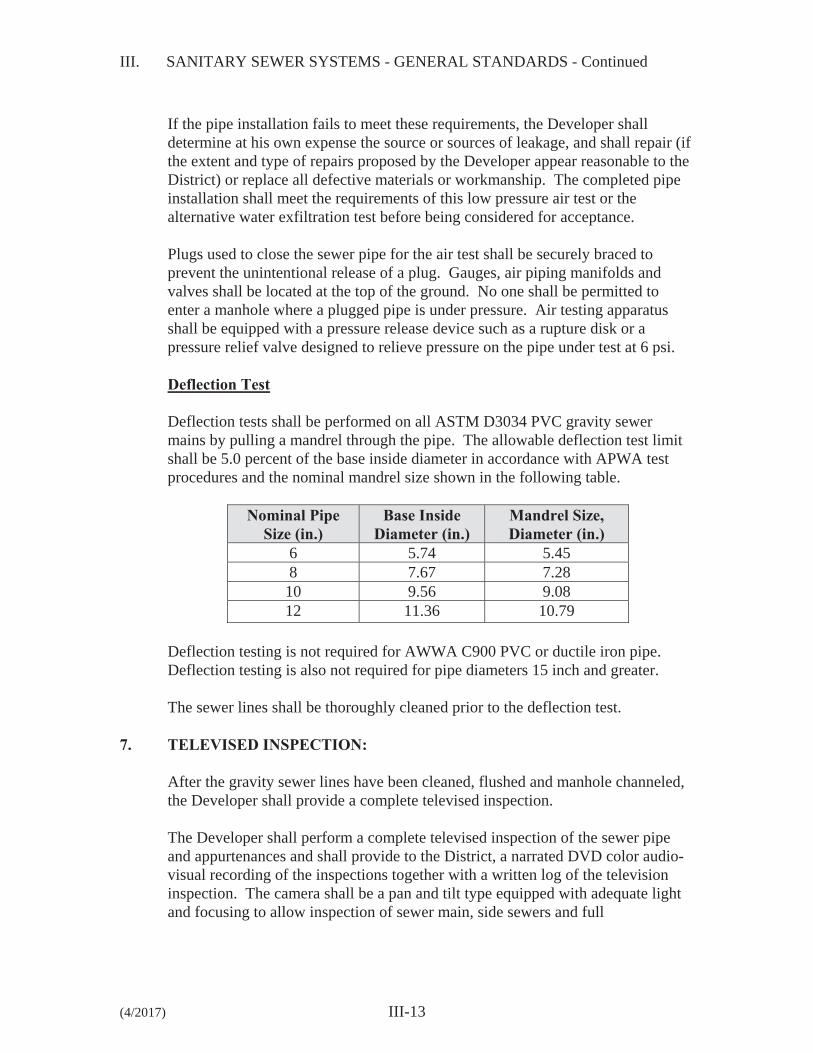
Deflection tests shall be performed on all ASTM D3034 PVC gravity sewer mains by pulling a mandrel through the pipe. The allowable deflection test limit shall be 5.0 percent of the base inside diameter in accordance with APWA test procedures and the nominal mandrel size shown in the following table.
Nominal Pipe Size (in.)
Base Inside Diameter (in.)
Mandrel Size, Diameter (in.)
6 5.74 5.45 8 7.67 7.28 10 9.56 9.08 12 11.36 10.79
Deflection testing is not required for AWWA C900 PVC or ductile iron pipe. Deflection testing is also not required for pipe diameters 15 inch and greater. The sewer lines shall be thoroughly cleaned prior to the deflection test.
7. TELEVISED INSPECTION:
After the gravity sewer lines have been cleaned, flushed and manhole channeled, the Developer shall provide a complete televised inspection. The Developer shall perform a complete televised inspection of the sewer pipe and appurtenances and shall provide to the District, a narrated DVD color audio-visual recording of the inspections together with a written log of the television inspection. The camera shall be a pan and tilt type equipped with adequate light and focusing to allow inspection of sewer main, side sewers and full
III. SANITARY SEWER SYSTEMS - GENERAL STANDARDS - Continued
(4/2017) III-14
circumference inspection of main line joints and fittings. The District shall determine if the quality of the televising is acceptable. Immediately prior to the televised inspection, the Developer shall run water through each sewer line for 5- to 10-minutes to provide water for detection of any adverse grade sections visible by the presence of ponded water. The camera shall be stopped periodically at the ponded areas and the depth of water shall be measured with a ball of known diameter on the pull line. During the inspection, all tees and other fittings shall be logged as to exact location within 1 percent maximum error in measurement, wherein accuracy is checked with various fittings and the terminating manhole. The District shall be notified 48 hours prior to any television inspection and this work shall be performed on a schedule to allow the District to witness the inspection. Any defects in material or installation identified by the television inspection shall be repaired as required by the District at the Developer’s expense. Sewer Video Requirements 1. Start videoing from the downstream manhole to upstream manhole.
2. The center of the downstream manhole will start at zero and the uphill
manhole footage will be finished at the center of the upstream manhole. Verbalize the side sewer with a station such at 1+64 along with writing on the screen to make it permanent on the video log.
3. Control the lighting power to best visualize the system including side
sewers. 4. Stop and video all fittings including the side sewer connections. Visualize
any joints that appear to not be normal such as wide gaps require video around the connection point to see if any gasket is showing. Verbalize and document on the video the fittings or any abnormalities.
5. Document ponding verbally as well as typing onto the screen which will
then be on the video log. Document the start of the pond to the end of the pond along with depth of the pond.
6. Video train to include 1-inch visible ball with graduated 1/8-inch indicator
rings.
III. SANITARY SEWER SYSTEMS - GENERAL STANDARDS - Continued
(4/2017) III-15
7. Make sure the selected camera is appropriate to the pipe material and diameter to create the best video record. The camera needs to be stabilized. The lack of traction from the camera creating a jumping video is not acceptable.
8. When videoing the inside of a manhole focus on the joints along with the
risers for the ring and cover. Turn the camera lights up when looking inside the manhole.
9. When looking up side sewers use the zoom and focus on any apparent
defects. 10. The video along with the manhole logs assist with verification of side
sewers for our as-builts. 11. Camera tractor speed needs to be kept at a consistent pace and not too fast. 12. When documenting on the video and video log, use stations for the tees
from the downstream manhole. 13. When documenting a tee for a side sewer use “tee left” or “tee right”
along with the stationing from the downstream manhole. 14. Verbalize on the recording anything documented on the log.
8. ADJUSTMENT OF NEW AND EXISTING UTILITY STRUCTURES TO GRADE:
This work consists of constructing and/or adjusting all new and existing utility structures encountered on the project to finished grade.
Asphalt Concrete Paving On asphalt concrete paving projects, the manholes shall not be adjusted until the final pavement is completed, at which time the center of each manhole lid shall be relocated from references previously established by the Developer. The pavement shall be cut as further described and base material removed to permit removal of the cover. The manhole shall then be brought to proper grade. Prior to commencing adjustment, a plywood and visqueen cover as approved by the District shall be placed over the manhole base and channel to protect them from debris.
III. SANITARY SEWER SYSTEMS - GENERAL STANDARDS - Continued
(4/2017) III-16
The asphalt concrete pavement shall be cut and removed to a neat circle, the diameter of which shall not exceed 48 inches or 14 inches from the outside diameter of the ductile iron frame, whichever is smaller. The ductile iron frame shall be brought up to desired grade, which shall conform to surrounding road surface. Adjustment to desired grade shall be made with the use of concrete adjustment rings or bricks. No cast or ductile iron adjustment rings will be allowed. An approved class of mortar (one part cement to two parts of plaster sand) shall be placed between adjustment rings or bricks and ductile iron frame to completely fill all voids and to provide a watertight seal. No rough or uneven surfaces will be permitted inside or out. Adjustment rings or brick shall be placed and aligned so as to provide vertical sides and vertical alignment of manhole steps and ladder. Adjustments in excess of 26 inches of depth of the 24-inch manhole neck shall require manhole section rings to raise the eccentric cone to within the adjustment ring tolerances. Check manhole specifications for minimum and maximum manhole adjustment and step requirements. Special care shall be exercised in all operations in order not to damage the manhole, frames and lids or other existing facilities. The annular spaces of the manhole frames shall be filled with 5/8-inch minus crushed gravel and compacted with hand tamper to within 2 inches of the top of the frame. Asphalt concrete patching shall not be carried out during wet ground conditions or when air temperature is below 50 degrees F. Asphalt concrete mix shall be at required temperature when placed. Before making the asphalt concrete repair, the edges of the existing asphalt concrete pavement and the outer edge of the casting shall be tack coated with hot asphalt cement. The remaining 2 inches shall then be filled with HMA and compacted with hand tampers and a patching roller.
The completed patch shall match the existing paved surface for texture, density and uniformity of grade. The joint between the patch and the existing pavement shall then be carefully painted with hot asphalt cement or asphalt emulsion and shall be immediately covered with dry paving sand before asphalt cement solidifies. All debris such as asphalt pavement, cement bags, etc., shall be removed and disposed of by Developer. Prior to acceptance of a project, manholes shall be cleaned of all debris and foreign material. All manhole steps and ladders shall be cleaned free of grout. Any damage occurring to the existing facilities due to the Developer’s operations shall be repaired at his own expense.
III. SANITARY SEWER SYSTEMS - GENERAL STANDARDS - Continued
(4/2017) III-17
Adjustment of Manholes in Easements Manholes in easement areas shall be adjusted to ensure drainage away from the manhole frame and cover. Pour a 4'-0" diameter by 12-inch-thick broom finished concrete collar around the manhole frame and cover, and marked with a green carsonite marker.
Adjustment of Valve Box Castings Adjustment of valve box castings shall be made in the same manner as for manholes.
9. FINAL ACCEPTANCE:
Prior to final inspection, all pipelines shall be flushed and cleaned and all debris removed. At the District’s discretion, gravity sewer lines shall be inspected for line and grade by checking each section between manholes for alignment. A full circle of light shall be seen by looking through the pipe at a light held in the manhole at the opposite end of the section of sewer line being inspected. Any corrections required in line and grade shall be made at the expense of the Developer. Visual confirmation will require confined space entry compliance and will normally be considered where settlement is suspected.
10. PRIVATE SIDE SEWERS:
Private side sewers are the extension of side sewer laterals located outside of the public rights-of-way or easements granted to the Silver Lake Water & Sewer District.
1. All sewer service connections to District facilities shall be gravity service.
2. The sewer pipe in the street right-of-way and District easements shall be
6-inch diameter, and shall have a 2 percent minimum grade. Construction in street rights-of-way shall be performed by a licensed side sewer contractor and requires a right-of-way use permit.
3. Private side sewer pipe for residential property shall be 4 inches or larger. Side sewer pipe for duplexes, multi-family, industrial, commercial, etc., shall be 6 inches or larger. Pipe material shall be ductile iron or PVC ASTM D3034, and shall be installed at 2 percent minimum grade (1/4-inch fall per foot). Construction on private property may be performed by owner, but requires a permit.
III. SANITARY SEWER SYSTEMS - GENERAL STANDARDS - Continued
(4/2017) III-18
4. Pipe shall be bedded with pea gravel or clean free draining sand.
5. Side sewer shall be inspected by the District prior to backfilling. Side sewer shall be plugged and tested in the presence of the District Inspector by filling with water. Leakage rate shall not exceed 0.31 gal./hr. for 4-inch pipe and 0.47 gal./hr. for 6-inch pipe, per 100 feet of pipe. Existing homes served by septic systems converting to District sewer service are to demonstrate proper abandonment of septic tank to Snohomish County Health Department Standards and WAC 246-272A-0300. The Contractor shall provide a copy of documentation regarding sewage pumping to the District.
6. On private property, minimum cover shall be 18 inches over top of pipe
from a point 30 inches out from house and continuing to the connection with the District sewer system.
7. Parallel water and sewer lines shall be 10-feet apart horizontally wherever
possible and have a vertical separation of 18 inches if a vertical crossing is necessary.
8. No more than 100 feet is allowed between cleanouts. Cleanouts are
required for bends equal to or greater than 90 degrees. Cleanout shall be a plugged tee or plugged wye lateral.
9. All pipe joints shall be rubber gasket type. 10. When required, “grease interceptor” to be outside the building and be of a
size and type certified by a professional engineer licensed in the State of Washington and reviewed by the District.
11. Backwater valves are required on all side sewers where potential occurs for flow to back into the private service. These valves shall be installed in a riser pipe, meter box, vault or manhole as necessary to allow access for maintenance.
12. Dwelling units defined by food preparation, bedroom and bathroom areas contained in a structure are primary connections. Secondary connections require preapproval by the District before sewer service can be offered.
a. Auxiliary dwelling units constructed on an existing served
property within an existing structure may be allowed subject to payment of connection charges.
b. Auxiliary dwelling units constructed on an existing served property in separate structures require separate side sewer connections to District mainline facilities.
III. SANITARY SEWER SYSTEMS - GENERAL STANDARDS - Continued
(4/2017) III-19
c. Recreational vehicle dumps are not allowed.
d. Small utility sink and toilet facilities in out buildings may be
allowed to connect to existing side sewers.
13. Side sewer installs to existing District mainline facilities in right-of-way are subject to special requirements:
a. Right-of-way permit required. Owner to pay all costs of obtaining
the permit and for any costs associated with full compliance with all permit obligations.
b. Owner to pay all costs of installation of side sewer.
c. The Owner shall enter into a Developer Extension Agreement (DEA) with the District, and will be required to meet the following conditions:
i. All District or District incurred inspection fees are to be
paid prior to and as a condition of connection.
ii. Comply with all District Standards, Conditions, Specifications, and requirements are applicable.
iii. Comply with all state, local and federal requirements apply.
iv. Preconstruction meeting with owner, owner contractor, and District is to be scheduled with the District prior to initiation of construction.
v. No connection to District facilities can be made without District or District Representative onsite.