section a – general information · end of pipe storm water management facilities (b-3) b2.04 ....
TRANSCRIPT
July 2011 Town of Whitby
TABLE OF CONTENTS
SECTION A – GENERAL INFORMATION A1.00 INTRODUCTIONS .....................................................................................................A – 1 A2.00 ENGINEERING DRAWINGS .....................................................................................A – 2 A2.01 General (A-2) A2.02 Drawing Requirements (A-3) A3.00 SUBMISSIONS AND APPROVALS – NEW DEVELOPMENT...................................A – 4 A3.01 First Submission (A-4) A3.02 Second and Subsequent Submissions (A-4) A3.03 Final Submissions (A-5) A4.00 ENGINEERING DRAWINGS – CAPITAL PROJECTS ..............................................A – 6 A4.01 General (A-6) A4.02 Drawing Requirements (A-6) A5.00 SUBMISSIONS AND APPROVALS – CAPITAL PROJECTS....................................A – 7 A5.01 General (A-7) A6.00 CONSTRUCTION ......................................................................................................A – 8 A6.01 General (A-8) A6.02 Project Meetings (A-8) A6.03 Construction Layout (A-9) A6.04 Tree and Plant Protection (A-9) A6.05 Material Testing (A-9) A6.06 Approved Materials (A-10) A6.07 Erosions and Sediment Control (A-10) A7.00 RECORD DRAWINGS.............................................................................................A – 11 A8.00 DEVELOPMENT ON PRIVATE SERVICES ............................................................A – 12 A8.01 General (A-12) A8.02 Private Water Supply and Sewage Disposal (A-12) A8.03 Driveways and Culverts (A-12) A8.04 Lot Grading (A-12)
July 2011 Town of Whitby
SECTION B – STORM DESIGN AND STORM WATER MANAGEMENT B1.00 GENERAL..................................................................................................................B – 1 B2.00 WATERSHED PLANNING/STORM WATER MANAGEMENT ..................................B – 1 B2.01 Lot Level Controls (B-2) B2.02 Conveyance Controls (B-2) B2.03 End of Pipe Storm Water Management Facilities (B-3) B2.04 Storm Water Quality Treatment Facility Requirements (B-4)
B3.00 HYDROLOGY AND DESIGN FLOW ......................................................................... B - 6 B3.01 Sub-Watershed Drainage Areas (B-6) B3.02 Major/Minor System (B-7) B3.03 Runoff Quantity (B-9) B3.04 Pipe Capacity (B-11) B3.05 Roughness Coefficients (B-14) B3.06 Velocity (B-14) B3.07 Minimum Sizes of Pipe (B-14) B3.08 Minimum Depth (B-14) B3.09 Maintenance Holes (B-14) B3.10 Catchbasins (B-16) B3.11 Pipe (B-17) B3.12 Inlet and Outlet Structures (B-17) B3.13 Storm Drain Connections (B-17) B3.14 Construction (B-19) B3.15 Materials (B-19) B4.00 WATER COURSE PROTECTION ...........................................................................B – 20
July 2011 Town of Whitby
SECTION C – ROADWAYS C1.00 GENERAL................................................................................................................. C – 1 C2.00 ROAD CLASSIFICATION AND PAVEMENT DESIGN ............................................. C – 1 C2.01 Road Classification(C-1) C2.02 Minimum Pavement Design (C-1) C3.00 GEOMETRIC DESIGN ............................................................................................. C – 2 C3.01 Minimum Geometric Design Criteria (C-2) C3.02 Horizontal Alignment (C-3) C3.03 Vertical Alignment (C-3) C3.04 Industrial Roads (C-4) C3.05 Roadside Ditches (C-4) C3.06 Subdivision Emergency Access (C-4) C4.00 ROAD PAVEMENT DESIGN.................................................................................... C – 5
C4.01 Geotechnical Report (C-5) C4.02 Splining Details for Eyebrows and Bulbs (C-6) C4.04 Temporary Turning Circle (C-6) C4.05 Intersections (C-6) C4.06 Location of Utilities (C-7) C4.07 Location of Community Super Mailboxes (C-7) C5.00 BOULEVARDS, SIDEWALKS AND WALKWAYS .................................................... C – 7 C5.01 Sidewalks (C-7) C5.02 Boulevards (C-8) C5.03 Walkways (C-8) C5.04 Multi-use Pathways (C-8) C6.00 DRIVEWAYS AND ENTRANCES............................................................................. C – 8 C6.01 Driveways (C-8) C6.02 Concrete Curb and Gutter (C-10) C7.00 ROADWAY CYCLING FACILITIES ........................................................................ C – 10 C7.01 Boulevard Multi-Use Paths (C-10) C7.02 Shared Use Lanes (C-10) C7.03 Bike Lanes (C-11) C7.04 Paved Shoulders (C-11) C8.00 CONSTRUCTION................................................................................................... C – 11
July 2011 Town of Whitby
SECTION D – LOT GRADING D1.00 GENERAL................................................................................................................. D – 1 D2.00 DESIGN.................................................................................................................... D – 1 D2.01 Lot Grading Design (D-1) D2.02 Drainage Swale Design (D-2) D3.00 DRAWING REQUIREMENTS................................................................................... D – 2 D4.00 INDIVIDUAL HOUSE SITING PLANS ...................................................................... D – 4 D4.01 Foundation Walls (D-4) D5.00 LOT GRADING REQUIREMENTS FOR INFILL HOUSING ...................................... D - 4 D5.01 Introduction (D-4) D5.02 Responsibility of the Grading Consultant (D-6) D5.03 Lot Grading Certificate (D-7) D5.04 Lot Grading Criteria for Infill Housing (D-8) D6.00 CONSTRUCTION REQUIREMENTS ....................................................................... D – 9 D7.00 “AS – CONSTRUCTED” CERTIFICATION............................................................... D – 9 D7.01 Foundation Control Certification (D-9) D7.02 Foundation Control Certificate (D-11) D7.03 As built Certification (D-12) SECTION E – STRUCTURES E1.00 GENERAL..................................................................................................................E – 1 E2.00 RETAINING WALLS ..................................................................................................E – 1 E3.00 CULVERTS AND BRIDGES ......................................................................................E – 2 E4.00 NOISE FENCE AND WALLS.....................................................................................E – 2
July 2011 Town of Whitby
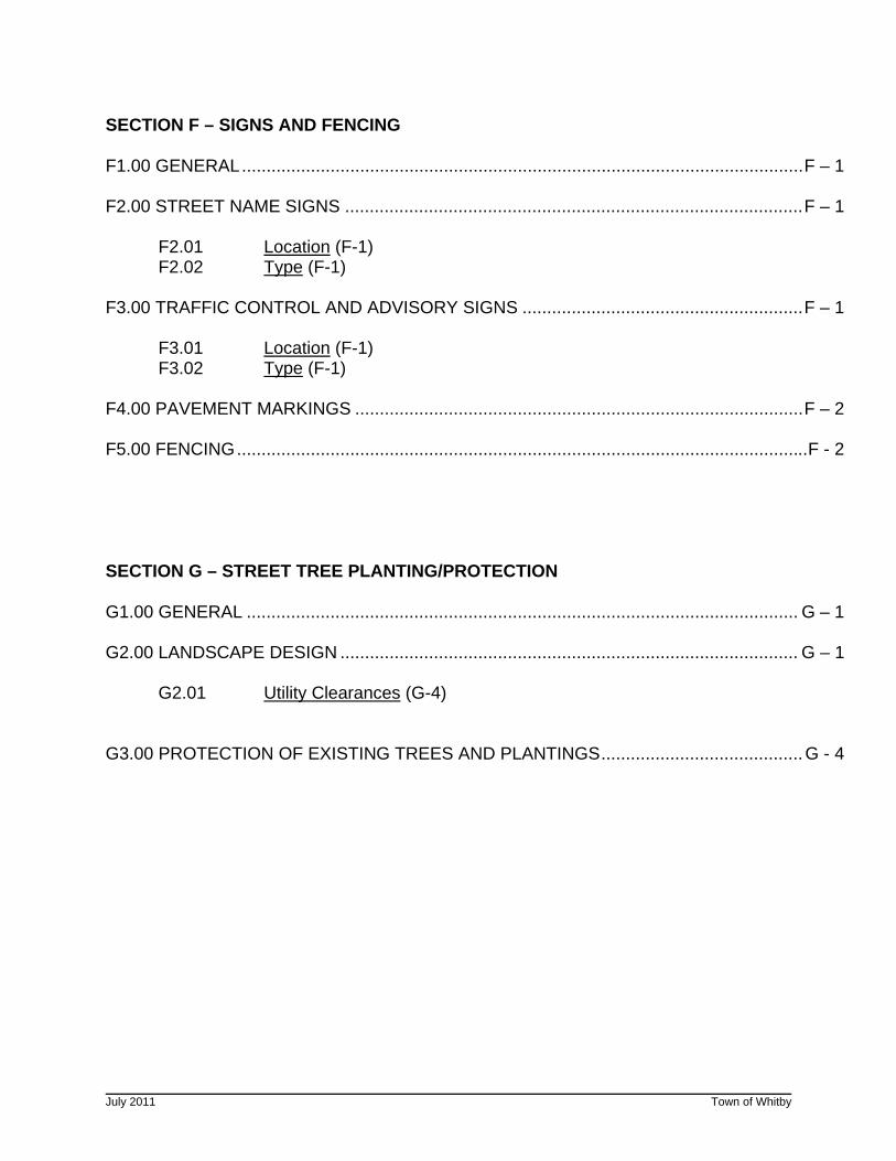
SECTION F – SIGNS AND FENCING F1.00 GENERAL..................................................................................................................F – 1 F2.00 STREET NAME SIGNS .............................................................................................F – 1 F2.01 Location (F-1) F2.02 Type (F-1) F3.00 TRAFFIC CONTROL AND ADVISORY SIGNS .........................................................F – 1 F3.01 Location (F-1) F3.02 Type (F-1) F4.00 PAVEMENT MARKINGS ...........................................................................................F – 2 F5.00 FENCING....................................................................................................................F - 2 SECTION G – STREET TREE PLANTING/PROTECTION G1.00 GENERAL ................................................................................................................ G – 1 G2.00 LANDSCAPE DESIGN ............................................................................................. G – 1 G2.01 Utility Clearances (G-4) G3.00 PROTECTION OF EXISTING TREES AND PLANTINGS.........................................G - 4
July 2011 Town of Whitby
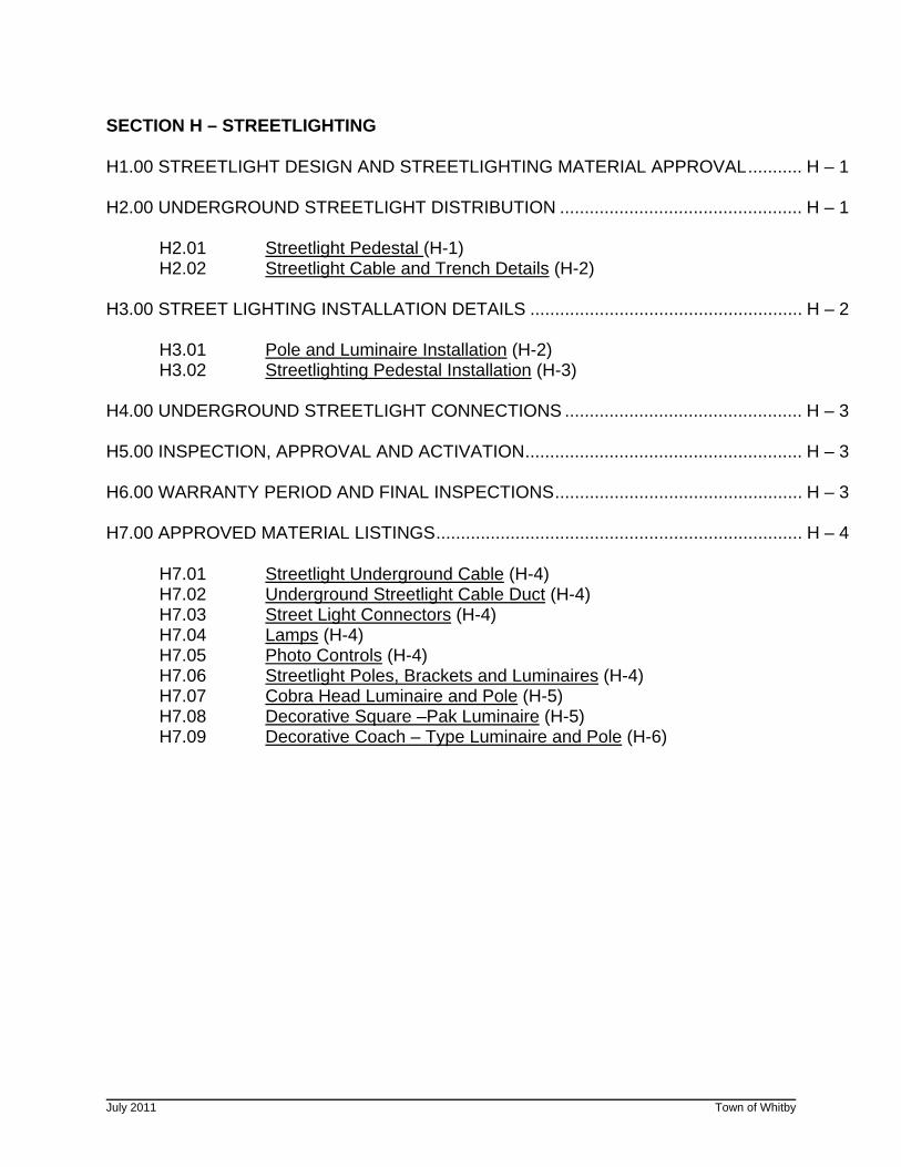
SECTION H – STREETLIGHTING H1.00 STREETLIGHT DESIGN AND STREETLIGHTING MATERIAL APPROVAL........... H – 1 H2.00 UNDERGROUND STREETLIGHT DISTRIBUTION ................................................. H – 1 H2.01 Streetlight Pedestal (H-1) H2.02 Streetlight Cable and Trench Details (H-2) H3.00 STREET LIGHTING INSTALLATION DETAILS ....................................................... H – 2 H3.01 Pole and Luminaire Installation (H-2) H3.02 Streetlighting Pedestal Installation (H-3) H4.00 UNDERGROUND STREETLIGHT CONNECTIONS ................................................ H – 3 H5.00 INSPECTION, APPROVAL AND ACTIVATION........................................................ H – 3 H6.00 WARRANTY PERIOD AND FINAL INSPECTIONS.................................................. H – 3 H7.00 APPROVED MATERIAL LISTINGS.......................................................................... H – 4 H7.01 Streetlight Underground Cable (H-4) H7.02 Underground Streetlight Cable Duct (H-4) H7.03 Street Light Connectors (H-4) H7.04 Lamps (H-4) H7.05 Photo Controls (H-4) H7.06 Streetlight Poles, Brackets and Luminaires (H-4) H7.07 Cobra Head Luminaire and Pole (H-5) H7.08 Decorative Square –Pak Luminaire (H-5) H7.09 Decorative Coach – Type Luminaire and Pole (H-6)
July 2011 Town of Whitby
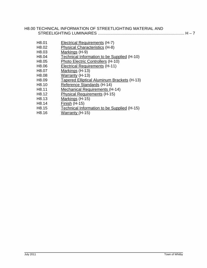
H8.00 TECHNICAL INFORMATION OF STREETLIGHTING MATERIAL AND STREELIGHTING LUMINAIRES ............................................................................ H – 7 H8.01 Electrical Requirements (H-7) H8.02 Physical Characteristics (H-8) H8.03 Markings (H-9) H8.04 Technical Information to be Supplied (H-10) H8.05 Photo Electric Controllers (H-10) H8.06 Electrical Requirements (H-11) H8.07 Markings (H-13) H8.08 Warranty (H-13) H8.09 Tapered Elliptical Aluminum Brackets (H-13) H8.10 Reference Standards (H-14) H8.11 Mechanical Requirements (H-14) H8.12 Physical Requirements (H-15) H8.13 Markings (H-15) H8.14 Finish (H-15) H8.15 Technical Information to be Supplied (H-15) H8.16 Warranty (H-15)
July 2011 Town of Whitby
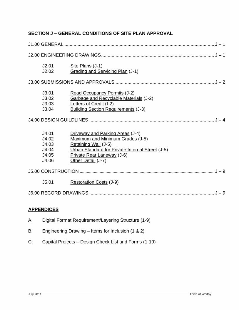
SECTION J – GENERAL CONDITIONS OF SITE PLAN APPROVAL J1.00 GENERAL .................................................................................................................. J – 1 J2.00 ENGINEERING DRAWINGS...................................................................................... J – 1 J2.01 Site Plans (J-1) J2.02 Grading and Servicing Plan (J-1) J3.00 SUBMISSIONS AND APPROVALS ........................................................................... J – 2 J3.01 Road Occupancy Permits (J-2) J3.02 Garbage and Recyclable Materials (J-2) J3.03 Letters of Credit (I-2) J3.04 Building Section Requirements (J-3) J4.00 DESIGN GUILDLINES ............................................................................................... J – 4
J4.01 Driveway and Parking Areas (J-4) J4.02 Maximum and Minimum Grades (J-5) J4.03 Retaining Wall (J-5) J4.04 Urban Standard for Private Internal Street (J-5) J4.05 Private Rear Laneway (J-6) J4.06 Other Detail (J-7) J5.00 CONSTRUCTION ...................................................................................................................J – 9 J5.01 Restoration Costs (J-9) J6.00 RECORD DRAWINGS ............................................................................................... J – 9 APPENDICES A. Digital Format Requirement/Layering Structure (1-9) B. Engineering Drawing – Items for Inclusion (1 & 2) C. Capital Projects – Design Check List and Forms (1-19)
Engineering Design Criteria Page A-1
July 2011 Town of Whitby
SECTION A - GENERAL INFORMATION A1.00 INTRODUCTION
The following engineering design criteria and requirements provide guidance to consulting engineers on design issues under the jurisdiction of the Town of Whitby Works Department. This includes storm drainage, Town of Whitby roads, lot grading, fencing, and street lighting. Separate design criteria and guidelines which may apply to a particular project are available from: Regional Municipality of Durham (Sanitary Sewer, Watermains and Regional Roads), Whitby Hydro (Electrical Distribution) Town of Whitby Planning Department, Region of Durham Planning Department, CLOCA/MNR (Watercourses and Environmentally Sensitive Areas), MTO (Provincial Highways), Railroads and other authorities when required.
These design criteria make reference to the Town of Whitby Standard Drawings found in Part 2 of this manual. They provide details on certain areas to clarify the design intent and are indexed as follows:
Section 100 - Storm Sewers
Section 200 - Curbs/Sidewalks
Section 300 - Grading
Section 400 - Geometrics
Section 500 - Miscellaneous
Engineering Design Criteria Page A-2
July 2011 Town of Whitby
A2.00 ENGINEERING DRAWINGS A2.01 General
A CD with Colour Tables, Line Tables, Sample Drawings, Symbols, Tables and Template Drawings is available upon request for the creations of all engineering drawing sets for subdivisions. Engineering drawing requirements for site plans are described in Section I and individual house siting plan requirements are described in Section D.
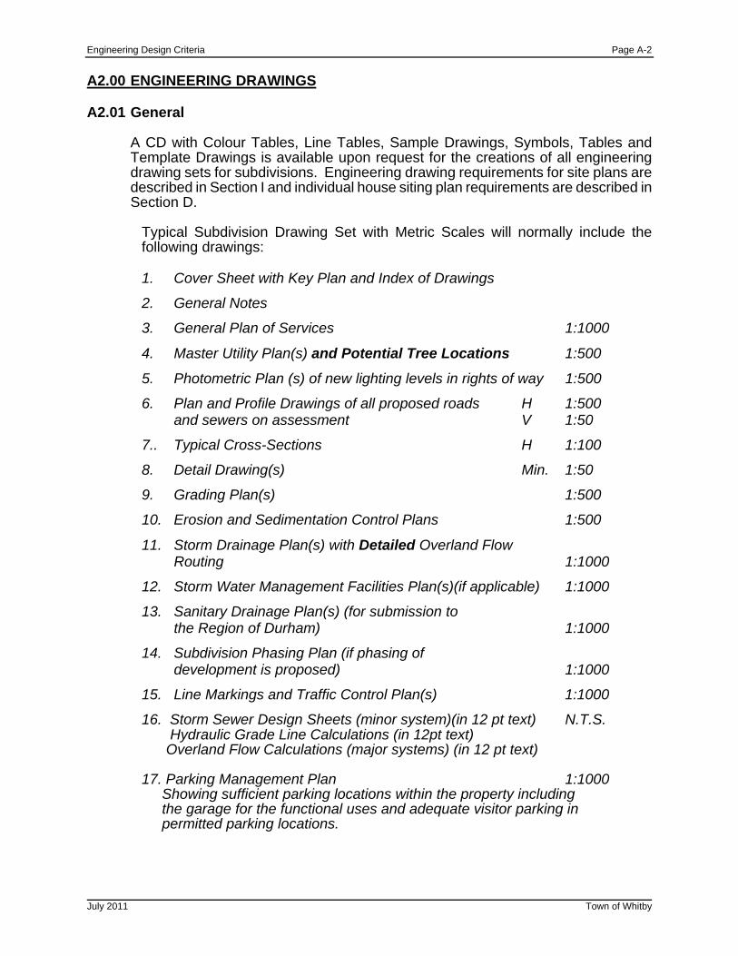
Typical Subdivision Drawing Set with Metric Scales will normally include the following drawings:
1. Cover Sheet with Key Plan and Index of Drawings
2. General Notes
3. General Plan of Services 1:1000
4. Master Utility Plan(s) and Potential Tree Locations 1:500
5. Photometric Plan (s) of new lighting levels in rights of way 1:500
6. Plan and Profile Drawings of all proposed roads H 1:500 and sewers on assessment V 1:50
7.. Typical Cross-Sections H 1:100
8. Detail Drawing(s) Min. 1:50
9. Grading Plan(s) 1:500
10. Erosion and Sedimentation Control Plans 1:500
11. Storm Drainage Plan(s) with Detailed Overland Flow Routing 1:1000
12. Storm Water Management Facilities Plan(s)(if applicable) 1:1000
13. Sanitary Drainage Plan(s) (for submission to the Region of Durham) 1:1000
14. Subdivision Phasing Plan (if phasing of development is proposed) 1:1000
15. Line Markings and Traffic Control Plan(s) 1:1000
16. Storm Sewer Design Sheets (minor system)(in 12 pt text) N.T.S. Hydraulic Grade Line Calculations (in 12pt text) Overland Flow Calculations (major systems) (in 12 pt text) 17. Parking Management Plan 1:1000 Showing sufficient parking locations within the property including the garage for the functional uses and adequate visitor parking in permitted parking locations.
Engineering Design Criteria Page A-3
July 2011 Town of Whitby
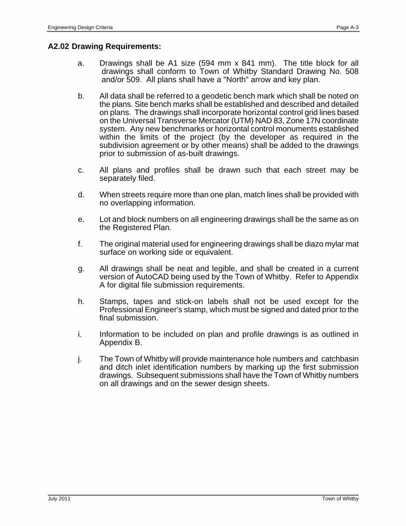
A2.02 Drawing Requirements:
a. Drawings shall be A1 size (594 mm x 841 mm). The title block for all drawings shall conform to Town of Whitby Standard Drawing No. 508 and/or 509. All plans shall have a "North" arrow and key plan.
b. All data shall be referred to a geodetic bench mark which shall be noted on
the plans. Site bench marks shall be established and described and detailed on plans. The drawings shall incorporate horizontal control grid lines based on the Universal Transverse Mercator (UTM) NAD 83, Zone 17N coordinate system. Any new benchmarks or horizontal control monuments established within the limits of the project (by the developer as required in the subdivision agreement or by other means) shall be added to the drawings prior to submission of as-built drawings.
c. All plans and profiles shall be drawn such that each street may be
separately filed. d. When streets require more than one plan, match lines shall be provided with
no overlapping information.
e. Lot and block numbers on all engineering drawings shall be the same as on the Registered Plan.
f. The original material used for engineering drawings shall be diazo mylar mat
surface on working side or equivalent.
g. All drawings shall be neat and legible, and shall be created in a current version of AutoCAD being used by the Town of Whitby. Refer to Appendix A for digital file submission requirements.
h. Stamps, tapes and stick-on labels shall not be used except for the
Professional Engineer's stamp, which must be signed and dated prior to the final submission.
i. Information to be included on plan and profile drawings is as outlined in
Appendix B.
j. The Town of Whitby will provide maintenance hole numbers and catchbasin and ditch inlet identification numbers by marking up the first submission drawings. Subsequent submissions shall have the Town of Whitby numbers on all drawings and on the sewer design sheets.
Engineering Design Criteria Page A-4
July 2011 Town of Whitby
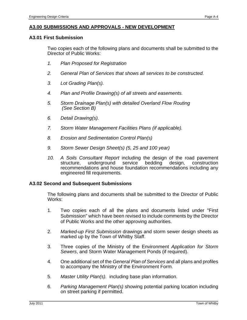
A3.00 SUBMISSIONS AND APPROVALS - NEW DEVELOPMENT A3.01 First Submission
Two copies each of the following plans and documents shall be submitted to the Director of Public Works:
1. Plan Proposed for Registration
2. General Plan of Services that shows all services to be constructed.
3. Lot Grading Plan(s).
4. Plan and Profile Drawing(s) of all streets and easements.
5. Storm Drainage Plan(s) with detailed Overland Flow Routing (See Section B)
6. Detail Drawing(s).
7. Storm Water Management Facilities Plans (if applicable).
8. Erosion and Sedimentation Control Plan(s)
9. Storm Sewer Design Sheet(s) (5, 25 and 100 year)
10. A Soils Consultant Report including the design of the road pavement
structure, underground service bedding design, construction recommendations and house foundation recommendations including any engineered fill requirements.
A3.02 Second and Subsequent Submissions
The following plans and documents shall be submitted to the Director of Public Works:
1. Two copies each of all the plans and documents listed under "First
Submission" which have been revised to include comments by the Director of Public Works and the other approving authorities.
2. Marked-up First Submission drawings and storm sewer design sheets as
marked up by the Town of Whitby Staff. 3. Three copies of the Ministry of the Environment Application for Storm
Sewers, and Storm Water Management Ponds (if required). 4. One additional set of the General Plan of Services and all plans and profiles
to accompany the Ministry of the Environment Form. 5. Master Utility Plan(s). including base plan information. 6. Parking Management Plan(s) showing potential parking location including
on street parking if permitted.
Engineering Design Criteria Page A-5
July 2011 Town of Whitby
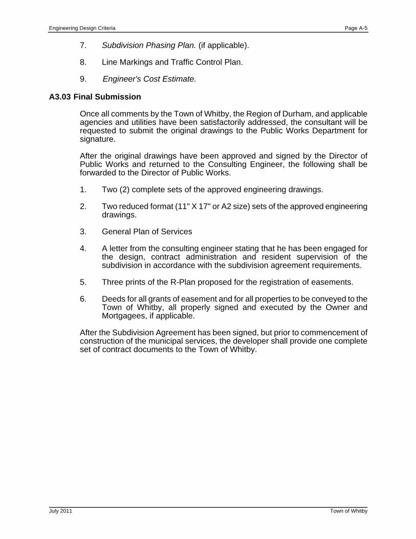
7. Subdivision Phasing Plan. (if applicable). 8. Line Markings and Traffic Control Plan. 9. Engineer's Cost Estimate.
A3.03 Final Submission
Once all comments by the Town of Whitby, the Region of Durham, and applicable agencies and utilities have been satisfactorily addressed, the consultant will be requested to submit the original drawings to the Public Works Department for signature.
After the original drawings have been approved and signed by the Director of Public Works and returned to the Consulting Engineer, the following shall be forwarded to the Director of Public Works.
1. Two (2) complete sets of the approved engineering drawings.
2. Two reduced format (11" X 17" or A2 size) sets of the approved engineering
drawings.
3. General Plan of Services
4. A letter from the consulting engineer stating that he has been engaged for the design, contract administration and resident supervision of the subdivision in accordance with the subdivision agreement requirements.
5. Three prints of the R-Plan proposed for the registration of easements.
6. Deeds for all grants of easement and for all properties to be conveyed to the
Town of Whitby, all properly signed and executed by the Owner and Mortgagees, if applicable.
After the Subdivision Agreement has been signed, but prior to commencement of construction of the municipal services, the developer shall provide one complete set of contract documents to the Town of Whitby.
Engineering Design Criteria Page A-6
July 2011 Town of Whitby
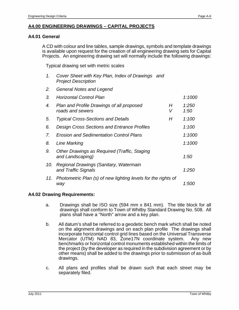
A4.00 ENGINEERING DRAWINGS – CAPITAL PROJECTS A4.01 General
A CD with colour and line tables, sample drawings, symbols and template drawings is available upon request for the creation of all engineering drawing sets for Capital Projects. An engineering drawing set will normally include the following drawings:
Typical drawing set with metric scales
1. Cover Sheet with Key Plan, Index of Drawings and Project Description
2. General Notes and Legend
3. Horizontal Control Plan 1:1000
4. Plan and Profile Drawings of all proposed H 1:250 roads and sewers V 1:50
5. Typical Cross-Sections and Details H 1:100
6. Design Cross Sections and Entrance Profiles 1:100
7. Erosion and Sedimentation Control Plans 1:1000
8. Line Marking 1:1000
9. Other Drawings as Required (Traffic, Staging and Landscaping) 1:50
10. Regional Drawings (Sanitary, Watermain and Traffic Signals 1:250
11. Photometric Plan (s) of new lighting levels for the rights of way 1:500
A4.02 Drawing Requirements:
a. Drawings shall be ISO size (594 mm x 841 mm). The title block for all drawings shall conform to Town of Whitby Standard Drawing No. 508. All plans shall have a "North" arrow and a key plan.
b. All datum’s shall be referred to a geodetic bench mark which shall be noted
on the alignment drawings and on each plan profile The drawings shall incorporate horizontal control grid lines based on the Universal Transverse Mercator (UTM) NAD 83, Zone17N coordinate system. Any new benchmarks or horizontal control monuments established within the limits of the project (by the developer as required in the subdivision agreement or by other means) shall be added to the drawings prior to submission of as-built drawings.
c. All plans and profiles shall be drawn such that each street may be
separately filed.
Engineering Design Criteria Page A-7
July 2011 Town of Whitby
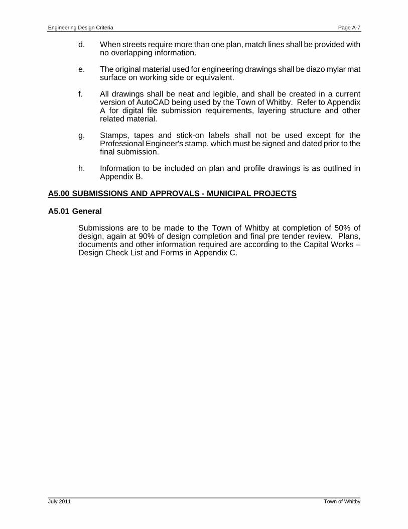
d. When streets require more than one plan, match lines shall be provided with
no overlapping information. e. The original material used for engineering drawings shall be diazo mylar mat
surface on working side or equivalent.
f. All drawings shall be neat and legible, and shall be created in a current version of AutoCAD being used by the Town of Whitby. Refer to Appendix A for digital file submission requirements, layering structure and other related material.
g. Stamps, tapes and stick-on labels shall not be used except for the
Professional Engineer's stamp, which must be signed and dated prior to the final submission.
h. Information to be included on plan and profile drawings is as outlined in
Appendix B. A5.00 SUBMISSIONS AND APPROVALS - MUNICIPAL PROJECTS A5.01 General
Submissions are to be made to the Town of Whitby at completion of 50% of design, again at 90% of design completion and final pre tender review. Plans, documents and other information required are according to the Capital Works – Design Check List and Forms in Appendix C.

Engineering Design Criteria Page A-8
July 2011 Town of Whitby
A6.00 CONSTRUCTION A6.01 General
Construction for new development works shall be arranged by the developer directly with any contractor who has proper experience and who shall provide Worker's Compensation Board clearance certificates initially and upon request as the work proceeds and prior to release of holdbacks. The developer shall retain a consulting engineer and qualified inspection and testing consultant(s) to oversee construction and certify that it is in accordance with applicable standards.
For construction of municipal works, the Town of Whitby will retain a qualified contractor directly and provide inspection services with Town of Whitby staff or a consulting engineer retained by the Town of Whitby.
Construction of all works in the Town of Whitby shall be in accordance with the current " Occupational Health and Safety Act and Regulations for Construction Projects" and other applicable legislation as well as " Traffic Control Manual for Roadway Work Operations". Construction shall generally conform to Ontario Provincial Standard Specifications and the Town of Whitby and Ontario Provincial Standard Drawings, as well as the specific contract specifications and drawings prepared for the work and approved by the Director of Public Works.
Construction of sanitary sewers and watermains in the Town of Whitby shall be done in accordance with Regional Municipality of Durham Standard Specifications for Construction of Watermains and Sanitary Sewers (Schedules C and D - latest edition). Note that other specifications and standards may apply in specific contracts as outlined in the contract documents.
A6.02 Project Meetings
The consulting engineer, contractor and Town of Whitby inspection staff shall meet at the construction site at regular intervals as determined by the Town of Whitby inspection staff during the course of construction to: monitor construction progress, discuss planned construction activity and potential problems, discuss outstanding questions or problems related to the work, and discuss any other business related to the work such as payments, change notices, etc.
Engineering Design Criteria Page A-9
July 2011 Town of Whitby
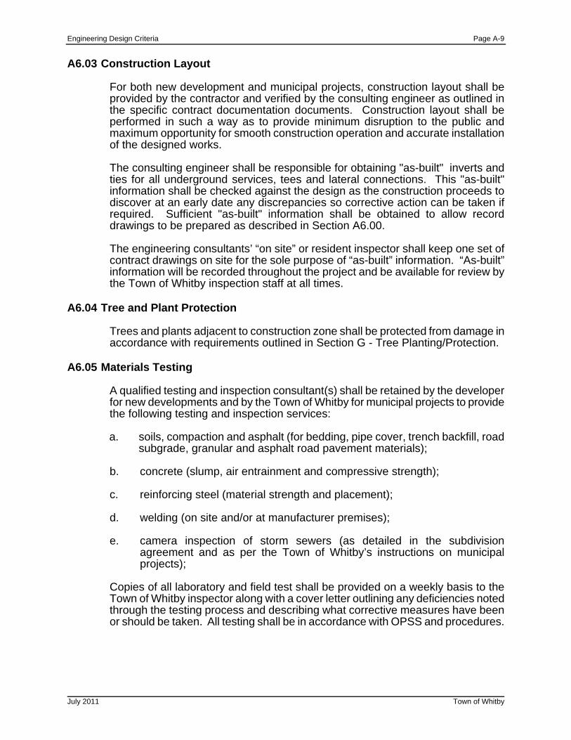
A6.03 Construction Layout
For both new development and municipal projects, construction layout shall be provided by the contractor and verified by the consulting engineer as outlined in the specific contract documentation documents. Construction layout shall be performed in such a way as to provide minimum disruption to the public and maximum opportunity for smooth construction operation and accurate installation of the designed works.
The consulting engineer shall be responsible for obtaining "as-built" inverts and ties for all underground services, tees and lateral connections. This "as-built" information shall be checked against the design as the construction proceeds to discover at an early date any discrepancies so corrective action can be taken if required. Sufficient "as-built" information shall be obtained to allow record drawings to be prepared as described in Section A6.00.
The engineering consultants’ “on site” or resident inspector shall keep one set of contract drawings on site for the sole purpose of “as-built” information. “As-built” information will be recorded throughout the project and be available for review by the Town of Whitby inspection staff at all times.
A6.04 Tree and Plant Protection
Trees and plants adjacent to construction zone shall be protected from damage in accordance with requirements outlined in Section G - Tree Planting/Protection.
A6.05 Materials Testing
A qualified testing and inspection consultant(s) shall be retained by the developer for new developments and by the Town of Whitby for municipal projects to provide the following testing and inspection services:
a. soils, compaction and asphalt (for bedding, pipe cover, trench backfill, road
subgrade, granular and asphalt road pavement materials);
b. concrete (slump, air entrainment and compressive strength);
c. reinforcing steel (material strength and placement);
d. welding (on site and/or at manufacturer premises);
e. camera inspection of storm sewers (as detailed in the subdivision agreement and as per the Town of Whitby’s instructions on municipal projects);
Copies of all laboratory and field test shall be provided on a weekly basis to the Town of Whitby inspector along with a cover letter outlining any deficiencies noted through the testing process and describing what corrective measures have been or should be taken. All testing shall be in accordance with OPSS and procedures.
Engineering Design Criteria Page A-10
July 2011 Town of Whitby
A6.06 Approved Materials
All construction in the Town of Whitby shall be done with materials which are on the Town of Whitby's Approved Products List, the Region of Durham's Approved Products List or Whitby Hydro’s Approved Products List. Each list is available upon request from the appropriate agency. The Town of Whitby Approved Products List is available at www.roadauthority.com . Materials must also meet specific requirements outlined in the contract drawings and specifications and are subject to acceptance testing by the developer or the Town of Whitby.
A6.07 Erosion and Sediment Control
General
Prior to the commencement of any on site work, the developer for the subdivision or the contractor for the municipal project must implement a site control and management plan to effectively reduce on site erosion and minimize the transport of silt off site, either overland or via the municipal storm sewer system, or into treed and/or environmentally sensitive areas within the development or project. It shall include provision to minimize wind blown dust and mud tracking onto adjacent roads. Details of this plan/drawings shall be prepared by the consulting engineer for the development and be included with the engineering submission(s) for approval by the Town of Whitby Public Works Department. For municipal projects similar plans are required (where applicable) with erosion and sediment control drawings required as part of the contract document.
Site Control and Management Plan/Drawings
This plan must address specific requirements for each stage of the construction as follows:
- clearing and grubbing - rough grading and servicing - street and building construction.
Typical accepted measures to mitigate erosion during construction are listed as follows: silt fencing, mud mats, interceptor swales, rock check dams, catchbasin buffers, sediment traps and sediment ponds with associated emergency spillways and extended detention outflow devices.
Other requirements may be necessary where creek or stream crossings for sewers and water mains; bridge or culvert construction across active streams; channel diversions; and outfalls to active streams are encountered. Plans shall outline measures to reduce the impact on the streams including the timing of construction activities to minimize disruption as required by other agencies.
The phasing of the subdivision development or municipal project must be taken into account during the design of the temporary erosion and sediment control measures including the location(s) for topsoil stockpiles. A primary consideration shall be to expose the smallest possible area of land to erosion for the shortest possible time.
Engineering Design Criteria Page A-11
July 2011 Town of Whitby
A7.00 RECORD DRAWINGS
Upon completion of construction and prior to assumption of services by the Town of Whitby, the original engineering drawings which have been revised to include as-built conditions, shall be submitted to the Department of Public Works for their permanent records. These drawings shall also be submitted in digital format in a current version of AutoCAD used by the Town of Whitby. Any other files and/or specifications required for plotting should be included with submission. "As-built" storm sewer design sheets should also be provided in digital spreadsheet format.
All digital files shall conform to the layering system and other requirements described in Appendix `A' - Digital Format Requirements. In addition to "as-built" drawings, the consultant shall also provide "as-built" service connection records as per Standard Drawings No. 510 and 511 which document the location and inverts of all buried service connection stubs.
All plan drawings shall incorporate the NAD 83, Zone 17 UTM co-ordinate grid and shall show the "as-built" locations of new benchmarks and horizontal control monuments.
The "as-built" engineering drawings shall be prepared using the final survey of the subdivision services and construction records.
Information required for the "as-built" engineering drawings include:
(a) Verification of location, survey of invert elevations of all sewers,
maintenance holes, catchbasins, and rear yard catchbasins. In the case of maintenance holes in easements, ditch inlet catchbasins and rear yard catchbasins and all sodded areas the rim elevation is also required.
(b) Distance between sewer maintenance holes, including pipe sizes and
calculated sewer grades. Sewer lengths are to be shown to the nearest 0.1m and sewer grades calculated to two decimal places. Text for "as-built" inverts, lengths and grades shall be drafted in boxes beside original design text, which shall be displayed in legible "strikeout" text.
(c) Verification of location of all curbs, sidewalks, light poles, tree planting and
fencing where applicable.
(d) Verification of location of transformers, utility pedestals, super mailboxes (if installed), transit pads, and utility crossings on the utility co-ordination plan(s).
(e) Verification of invert elevations and widths in overland flow routes and
capacity at outlets including curb heights, sidewalk elevation, boulevard slopes and unobstructed widths.
Where there is a major difference between the design and "as-built" data, the Consultant is required, in writing, to explain the discrepancy and verify that the "as-built" discrepancy does not adversely affect the intent of the services.
Engineering Design Criteria Page A-12
July 2011 Town of Whitby
Within five years after final acceptance, the Town of Whitby may request the Consultant to revise and recheck the "as-built" drawings if discrepancies between the "as-built" drawings and the field conditions are found.
A8.00 DEVELOPMENT WITH PRIVATE SERVICES A8.01 General
As mentioned in Section A1.00 - General, these engineering design criteria specifically relate to issues under the jurisdiction of the Town of Whitby Public Works Department. Other agencies and bodies also govern developments with private services and the Town of Whitby Planning Department should be contacted for site plan approval requirements. The Public Works Department will review site plans and reports supporting the development.
A8.02 Private Water Supply and Sewage Disposal
Where development is proposed on privately serviced lots, the developer shall retain qualified consultant(s) who specialize in the design of private wells and sewage systems. The private water supply system (wells) shall be constructed in accordance with the Ontario Water Resources Act, Durham Region Department of Health and applicable Ontario Regulations.
All private waste disposal systems shall be constructed in accordance with the Ontario Environmental Protection Act, Durham Region Department of Health and applicable Ontario Regulations.
A8.03 Driveways and Culverts
Where the developer is servicing lots along an existing ditched roadway, arrangements must be made with the applicable road authority (Town of Whitby, Region of Durham or Ministry of Transportation of Ontario) to have the driveway location approved and to have driveway culverts installed in the existing roadside ditch.
Driveway design shall match the grade at the back of the existing shoulder and shall provide a minimum 6.0m long level (-1% to +3%) platform behind the shoulder.
A8.04 Lot Grading
Grading design shall be in accordance with Section D - Lot Grading as applicable and shall also be in accordance with requirements of the planning department for tree and natural environment preservation and shall implement the design requirements for the sewage disposal system.
Lot grading certification shall be provided by the developer's Consulting Engineer and/or sewage system consultant who shall certify that the "as-built" grading is in conformity with the approved site plan and that the sewage disposal system has been installed properly and in accordance with the approved design. Where “as-built” conditions are not in conformity with the approved design, a detailed letter
Engineering Design Criteria Page A-13
July 2011 Town of Whitby
outlining differences, reasons and any impacts shall be provided by the Consulting Engineer.
Lot grading requirements for 'Infill' lots are detailed in Section D5.0
SECTION B - STORM DESIGN AND STORM WATER MANAGEMENT B1.00 GENERAL
Storm drainage design and storm water management are relatively dynamic areas of engineering design. This chapter is intended to provide guidance to the designer but is not intended to inhibit newer standard practice or carefully thought out innovation. Designers are encouraged to discuss their design plans with the Director of Public Works early in the design process so that all efforts can be productive.
B2.00 WATERSHED PLANNING/STORM WATER MANAGEMENT
The Town of Whitby drains into 4 different watersheds. Sub-watershed plans have been prepared for the Lynde Creek and Oshawa Creek and a master drainage plan has been prepared for Pringle Creek. Storm drainage facilities within these watersheds must conform to these plans.
Since no reports have yet been prepared for the Corbett Creek , specific attention and prior consultation with the Director of Public Works and Central Lake Ontario Conservation Authority (CLOCA) must be arranged when designing storm drainage systems tributary to these watercourses.
CLOCA has also endorsed “Technical Guidelines for Storm Water Management Submissions” June 2007, and this document shall be referred to (or latest editions) when preparing a storm water management submissions to the Town of Whitby. For all new development, a storm water management (SWM) report shall be prepared which addresses the following, in general;
(a) storm water quantity
(b) storm water quality
(c) erosion potential (new outfalls, channels and along existing stream banks)
(d) baseflow maintenance (water balance/budget)
The SWM report should address these issues within the framework of the sub-watershed plan, where one exists. The Storm Water Management Practices - Planning and Design Manual (MOE; March 2003 or latest edition) provides extensive guidelines for SWM plan selection in the absence of a sub-watershed plan. The SWM plan must address all of the concerns of the other governing agencies (e.g. MOE, MNR, CLOCA, DFO, MTO etc.). Where appropriate MTO Drainage Design Standards January 2008 or as amended shall be referenced.
The SWM plan must address the issues outlined in Sections B2.01 to B2.04.
Engineering Design Criteria Page B-2
July 2011 Town of Whitby
B2.01 Lot Level Controls
(a) Minimum lot grades shall be 2.0%. (b) Rear roof leaders for townhouses shall be connected to storm sewers, other
rear roof leaders shall not be connected to storm sewers but will discharge to splash pads draining to sodded portions of the lot. Roof leaders discharging to the front yard shall be connected to the storm sewer. The use of rainwater harvesting (e.g. rain barrels, cisterns, etc.) where the roof leaders are allowed to be disconnected shall be encouraged wherever feasible to not only reduce storm water runoff but to conserve the potable water supply as the captured rain water can be used for irrigation purposes.
(c) Roof top and parking lot storage shall be provided on non-residential
developments so that post-development flows do not exceed pre-development flows up to the 5 year storm. If downstream SWM controls are in place (e.g. end of pipe controls) and the receiving storm sewers have been sized appropriately, then it shall be demonstrated that the 100 year storm does not exceed the allotted minor system flows for the site (e.g. major system control). Note that for specific sites with downstream constraints, more stringent requirements may be established by the Director of Public Works.
(d) Underground storage shall be permitted to achieve quantity control of post-
development flows. Only roof top flows and pre-treated flows shall be permitted to infiltrate from underground storage chambers
B2.02 Conveyance Controls
(a) Grassed swales shall be used wherever practical.
(b) Foundation drains shall drain via gravity to the storm sewers wherever practical. Calculations shall be provided to demonstrate that the hydraulic grade line (HGL) does not get higher than 0.5m below underside of basement floor elevations during a 100 year storm. While it is recognized that storm sewers and catchbasin spacing designed using the Town of Whitby criteria may or may not capture the 100 year event, the onus is on the consultant to demonstrate the actual flow capture within the proposed storm sewer system using the Town of Whitby’s 100 year design event. Alternatively, the 100 year flow can be assumed to be captured. These flows shall then be used in the HGL calculations. Inlet Control Devices (ICD’s) will be considered to limit the flows into the storm sewer system if necessary. The starting elevation for the HGL calculation shall be the higher of the 100 year water surface elevation within the receiving system (downstream SWM Pond, floodplain, etc.) or the obvert of the outlet pipe from the system. The HGL is to be plotted on all plan and profile drawings and calculations provided.
Engineering Design Criteria Page B-3
July 2011 Town of Whitby
(c) Sufficient calculations shall be provided to demonstrate that the overland
flow resulting from a 100 year storm is contained within the road right-of-way and conveyance routes are designed for this purpose. The design of the major system shall not be less than the difference between 1.25 times the 100 year design flow and the 5 year design flow. Catchbasin and ditch inlet capture flows shall be based on MTO recommendations for the depths of overland flow.
(d) Required infliltration/exfilitration galleries shall be provided with effective
pre-treatment of incoming storm water flows (if applicable) to limit the potential clogging of the galleries.
(e) Oil-Grit Separators (OGS) are required on sites where there is a potential
for hazardous spills (e.g. fuel filling areas). On other site plans, OGS’s will be assessed on a site by site basis as deemed necessary based on the watershed constraints. Where OGS’s are deemed unwarranted, a cash in lieu contribution may be considered, subject to the approval of the Director of Public Works.
B2.03 End-of-Pipe Storm Water Management Facilities
(a) The Storm Water Management Practices - Planning and Design Manual (MOE; March 2003 or latest edition) outlines several alternative end-of-pipe SWM facilities. Wet ponds are the preferred method for storm water quality and quantity control.
(b) The required storage volume for storm water quality control will be based on
enhanced protection (formerly Level 1 protection) and the 24 hour extended detention of the runoff generated by a short duration 4 hour 25mm storm event. For stream bank erosion protection, the aforementioned extended detention criteria shall be used, unless there is a requirement for an additional analysis as determined by the Director of Public Works or CLOCA.
(c) The required storage volume for storm water quantity control will be based
on the control of peak post development runoff rates to the peak pre-development runoff rate for the 2 through 100 year storms unless otherwise approved by the Town of Whitby and/or CLOCA. OTTHYMO or equivalent simulations shall be conducted to quantify the pre and post development runoff rates and the required storage volume. A range of design storms (e.g. 2 to 100 year return period) shall be analyzed in order to identify the operation of the system over a range of flows.
(d) the SWM report shall also address the following issues:
! landscaping, ! operation and maintenance, ! erosion and sediment control (both during and after construction), ! and safety.
Engineering Design Criteria Page B-4
July 2011 Town of Whitby
B2.04 Storm Water Quality Treatment Facility Requirements
Stormwater quality facilities shall, as minimum requirements, include design and maintenance enhancements as outlined 'The Storm Water Management Practices Planning and Design Manual; (MOE; March 2003 or latest edition) and as follows:
(a) Access - 4.0m wide maintenance roads with a maximum 8.0% longitudinal
slope and a maximum 2.0% crossfall shall be provided to access pond inlet and outlet structures, by-pass maintenance holes, the bottom of forebays and the main cell. The roads shall be designed for heavy equipment required for sediment removal and depending on grade, may be paved with asphalt, granular surface or open cell concrete block. Special attention is to be paid to the access roads above and below the normal water level (permanent pool) to account for the freeze/thaw effect of the normal water level. Turnaround areas shall be provided as required and a minimum centerline radius of 12.0m. Removable bollards are to be placed at the maintenance access point from the public right of way. Bollards to be locked with a Master Lock Pro Series High Security Model #6327, body with 2 5/8”, shackle clearance 3/4” and shackle diameter is 7/16”. Locks to be purchased from and installed by the Town of Whitby’s Operations Centre.
(b) Forebay - shall be provided to facilitate maintenance by concentrating
sedimentation at the inlet area of the pond. The forebay area should have a length to width ratio greater than 2, be greater than 1.0 m deep to minimize bottom scouring activity; be less than 1/3 the total pond area, have less than 20% of the total permanent pool required and be designed to accommodate 10 years sediment accumulation. The forebay berm shall be set at the normal water level and be a minimum of 2.0 m wide and have flow through culverts and inverts set at the predicted 10 year sediment level or 0.6m, whichever is greater and have a minimum of 0.3 m cover to the top of the forebay berm.
(c) Sediment drying area - where feasible, a sediment drying area is to be
located adjacent to the forebay area to facilitate dewatering of sediment prior to its removal from the site to an approved disposal area. This area is to be sized based on the predicted 10 year sediment volume piled 1.0 m high, have a minimum 2.0% and maximum 5.0% crossfall directed back into the pond and have a surface treatment consistent with maintenance access road.
(d) Maintenance/draw down pipe - shall be provided with valve control to permit
gravity draining of the pond to 0.5 m of the pond bottom for routine pond maintenance and sediment removal. If gravity flow is not feasible, a suitable pumping protocol and associated structures are to be designed and detailed on the pond drawings.
(e) Inlet Structure – storm sewer inlets into the pond are to be designed such
that the invert is at or above the normal water lever (permanent pool elevation). The Town of Whitby will not entertain submerged inlets.
(f) Outlet structures – bottom draw outlet structures shall be used in all
instances and shall be located a minimum of 1.0 m off the pond bottom.
Engineering Design Criteria Page B-5
July 2011 Town of Whitby
(g) Shut off capability - shall be provided to stop the extended detention portion
of the flow out of the pond (if feasible) in the event of a spill in the drainage area.
(h) Winter drainage outlet - shall be a design consideration to allow pond
drainage above the pond ice level in the event of significant runoff due to winter thaws. Elements d), e) and g) shall be contained in a concrete pre-cast maintenance hole.
(i) Maintenance bypass – details on the methodology of by-passing flows shall
be provided to divert all flow from the pond during maintenance and sediment removal procedures.
(j) Pond bottom - the pond shall be provided with a hard bottom if native soils
are not strong enough to support sediment removal activities and equipment. This shall be confirmed by a qualified Soils Consultant and submitted to the Town of Whitby.
(k) Pond liner – a geotechnical investigation for the pond shall be completed
detailing the need for liners and/or construction related methodologies in the event groundwater is encountered.
(l) Side slopes - for safety reasons a 2.0 m wide safety platform with a
maximum 5% crossfall is to be provided above the normal water level. Side slopes above the safety platform are to be maximum 4:1. Side slopes below the normal water level are to be maximum 4:1.
(m) Top of berm – perimeter berms shall be a minimum of 3.0 m wide where
trail or maintenance access is not located on the berm. Anything narrower shall be substantiated by a Soils Consultant.
(n) Overflow spillway – shall be incorporated to provide relief to the system in
the event of a severe storm event or blockage of the drainage system. The 100 year storm flows or maximum pond design storm flows, shall be used in the overflow design assuming the pond is full and all outlets from the pond are 100% blocked. A 0.15 m freeboard to the top of slope around the perimeter of the pond from the emergency water level elevation shall be maintained. The invert of the spillway shall be at or above the 100 year or highest design water level within the pond.
(o) Warning signage – warning signage is to be installed near pedestrian traffic
routes or walkways located adjacent to or within the storm water management block. The number of signs to be provided will be determined by the Town of Whitby on a site by site basis. Signs are to conform to the Town of Whitby standard and shall be provided by the developer. Signs shall be purchased from the Town of Whitby Operations Centre.
(p) Fencing –fencing will be required around the perimeter of the storm water
management block unless otherwise deemed by the Town of Whitby. Fencing to be as per the Town of Whitby standard drawings and criteria.
Engineering Design Criteria Page B-6
July 2011 Town of Whitby
(q) Provision for Algae Control – Excessive algae growth can be a problem in
some SWM facilities, particularly in catchment areas subject to high nutrient loads. Excessive algae growth can compromise the quality of water within the pond as well as the functional effectiveness of the pond. Algae can clog outlet structures and can render a pond unsightly. Dead and decaying algae can yield an odour which is offensive to neighbouring residents. To control algae growth, barley straw bags should be installed around the perimeter of the pond prior to commissioning. A kilogram of barley straw is required for each 1,000m2 of pond surface area. The straw should be distributed at a minimum rate of 3kg/bag. The bags are to be installed off shore of the pond edge and anchored with concrete blocks. Fresh barley straw bags are to be installed in the pond in the spring of each of the two years prior to assumption and finally upon assumption of the facility.
(r) As-built certification – prior to assumption of the subdivision all design
aspects of the SWM pond shall be certified by the consulting engineer including, but not limited to, storage volumes and elevations, both permanent pool and active requirements, control structures sizes and inverts, all storm pipe sizes and inverts, etc.. any hydrologic modeling used in the design of the pond shall be updated based on the as-built conditions and submitted to the Town of Whitby for review. Sediment accumulations shall be removed to the original pond design volume and disposed of off site to an approved disposal location. A revised storm water management report shall be prepared to reflect the as-built condition.
B3.00 HYDROLOGY AND DESIGN FLOWS B3.01 Sub-Watershed Drainage Areas
The sub-watershed area shall be determined from contour plans and verified in the field where necessary and shall include all areas that naturally drain into the system and any fringe areas not provided for in adjacent storm drainage areas, as well as other areas which may become tributary by reason of regrading. Further information may be obtained from the Public Works Department.
A plan of the sub-watershed area shall be prepared, to scale 1:1000 or as appropriate, depending on the size of the area, and shall show all streets, lots and watercourses affected. The intended storm sewer system shall be shown on this plan including each maintenance hole numbered consecutively* for design reference. Maintenance holes shall be located at each and every change of pipe size, grade and alignment.
Maintenance holes shall be the tributary points in design and areas tributary to each maintenance hole shall be clearly outlined on the storm drainage area plan and the area in hectares (to two decimal places) clearly shown, preferably in a circle 15 mm in diameter with the runoff coefficient also shown.
for example: 4.67 ha
0.5
* see A2.02 (j) for Town of Whitby maintenance hole numbering
Engineering Design Criteria Page B-7
July 2011 Town of Whitby
In cases where areas of different runoff coefficients may be tributary to one maintenance hole, the areas tributary to the maintenance hole shall be individually outlined with small arrows from the boundary line of the area showing the direction to the maintenance hole. In determining tributary areas to maintenance holes, the proposed grading of lots must be considered and taken into account in order to maintain consistency in design. Catchment areas tributary to catchbasins and other inlets shall also be used where the detailed interaction of the major and minor system flows is being analyzed.
In the case of large areas under single ownership, such as shopping centres, apartment developments, schools, etc., the design shall be prepared on the basis of the whole area being tributary to a maintenance hole in an abutting storm sewer unless more than one sewer connection will be necessary to serve the property in question, in which case the appropriate area tributary to each sewer connection shall be clearly shown and taken into account in the design of the storm sewer.
In lieu of precise information on development on the whole or any part of a watershed area, reference shall be made to the latest zoning plan issued by the Planning Department in order to select the correct values of runoff coefficient to be used in the design and the areas to which they shall be applied.
B3.02 Major/Minor System B3.02.1 Overland Flow Routing Plan
A detailed plan shall be provided that shows the overland flow routing, including major system maximum flow rates, maximum depths of flow in the gutter, maximum extents of flows, maximum velocities on landscaped areas and direction of flows. These values shall be shown for all significant changes in direction or slope and at all outlets for combinations of overland flows. The capacity of the overland flow routes shall be demonstrated by calculations acceptable to the Director of Public Works. Overland flow shall be designed to be on public property or dedicated easements. Overland flow shall be contained within the right of way and shall discharge to public parks and open space blocks wherever possible. Where it is not possible to contain the overland flow on public property, easements for overland flow inundation on private property shall be provided. The extent of overland flow inundation shall include the flow depth as well as the static ponding depth. The energy grade line of the flow shall be used as the minimum elevation for the protection of private property.
Engineering Design Criteria Page B-8
July 2011 Town of Whitby
B3.02.2 Major/Minor System Design
The storm drainage system shall be designed with the minor, or storm sewer system sized to convey the 1:5 year storm and the major or overland system designed to convey the 100 year storm. To account for a decrease in the imperviousness during major storms, the recommended safety factors as identified within MTO’s Drainage Design Standards 2008 as amended shall be used. For the 100 year storm, the factor shall be 1.25 times the calculated peak flow using the peak intensity factor of the 100 year storm. The design flow of the major system shall not be less than the difference between 1:25 times the 100 year design flow and the 5 year design flow (assumed to be captured by the minor system). Q(major) = 1.25 * Q(100) – Q (5) All overland flow calculations shall be based on this flow rate.
B3.02.3 Maximum Depth of Overland Flow For all Town of Whitby roads, the maximum gutter depth from the overland flow depth and static ponding shall not be more than 0.40m. The maximum centre line depth of overland flow on the Town of Whitby roads shall be as per the following: Local Streets 0.20 m Collector Roads 0.15 m Arterial Roads 0.10 m Under no circumstances shall the maximum centre line depth of an overland flow exceed 0.30 m on routes determined to be Emergency Accesses. The maximum depth of flow and the maximum velocity on other roads shall be as directed by the road authority having jurisdiction. Static ponding depth shall be either to the minimum spill elevation or the calculated depth for the ponding volume for the worst case storm event duration and intensity plus 0.05 m. Flow depth shall be based on accepted hydraulic principles such as Manning’s open channel calculations or weir flow depth. Downstream flow depths during peak events may be reduced to account for upstream storage in the overland flow route.
B3.02.4 Sanitary Sewer Infiltration Sanitary sewer maintenance hole covers in the overland flow route shall be protected from infiltration as per Regional standards.
Engineering Design Criteria Page B-9
July 2011 Town of Whitby
B3.02.5 Inlet Protection
To determine if inlet protection is required, the unrestricted capacity of a catchbasin or ditch inlet in the 1:100 year design flow shall be compared to the maximum 1:5 year design flow for the local inlet catchment area. The unrestricted capacity of the inlet at the calculated depth of flow shall be based on the MTO Drainage Management Manual Design Charts. Where the minor system is not designed to handle the 1:100 year design flow, the inlets shall be protected against surcharge by inlet control devices wherever the unrestricted inlet capacity exceeds the 1:5 year design flow for the inlet. The allowable 1:5 year design flow for the inlet must be adjusted to account for flows from directly connected downspouts and other inlets in the local inlet catchment area. Inlet control devices used for inlet protection to the 1:5 year design flow on public property shall have framed inlet controls with removable orifice plates to permit maintenance and cleaning. All inlet control devices used for quantity control on private property that restrict flows to less than the 1:5 year design flow shall be tamper proof. Orifices smaller than 75 mm in diameter (or equivalent area) shall be protected from blockage as a result of the possible accumulation of debris.
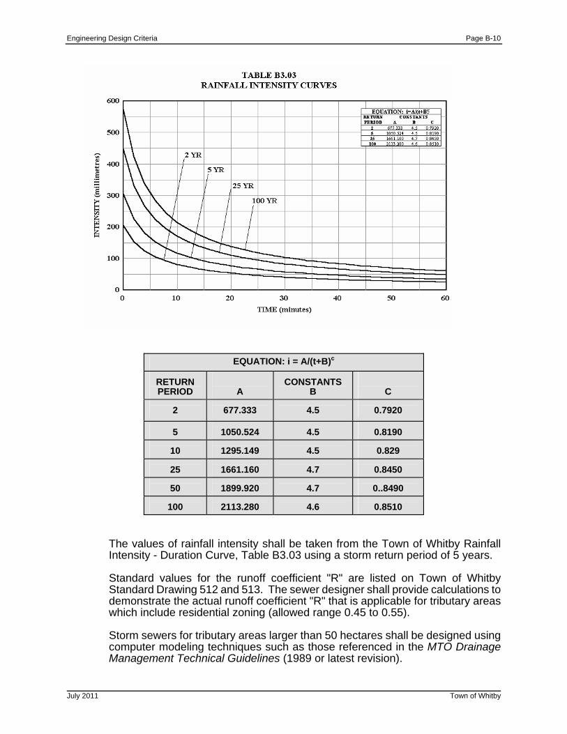
B3.03 Runoff Quantity
The design of the storm sewers shall be computed on the Town of Whitby Storm Sewer Design Sheets, Standard Drawing No. 513 format. All storm sewers draining tributary areas less than 5 hectares shall be designed according to the Modified Rational Formula where:
Q = 2.78 * A * I * R
A = Area (hectares) I = Average rainfall intensity - (mm/hr) R = Runoff coefficient Q = Runoff quantity (litres/sec.)
Engineering Design Criteria Page B-10
EQUATION: i = A/(t+B)c
RETURN PERIOD
A
CONSTANTS
B
C
2
677.333
4.5
0.7920
5
1050.524
4.5
0.8190
10
1295.149
4.5
0.829
25
1661.160
4.7
0.8450
50
1899.920
4.7
0..8490
100
2113.280
4.6
0.8510
The values of rainfall intensity shall be taken from the Town of Whitby Rainfall Intensity - Duration Curve, Table B3.03 using a storm return period of 5 years. Standard values for the runoff coefficient "R" are listed on Town of Whitby Standard Drawing 512 and 513. The sewer designer shall provide calculations to demonstrate the actual runoff coefficient "R" that is applicable for tributary areas which include residential zoning (allowed range 0.45 to 0.55).
Storm sewers for tributary areas larger than 50 hectares shall be designed using computer modeling techniques such as those referenced in the MTO Drainage Management Technical Guidelines (1989 or latest revision).
July 2011 Town of Whitby
Engineering Design Criteria Page B-11
July 2011 Town of Whitby
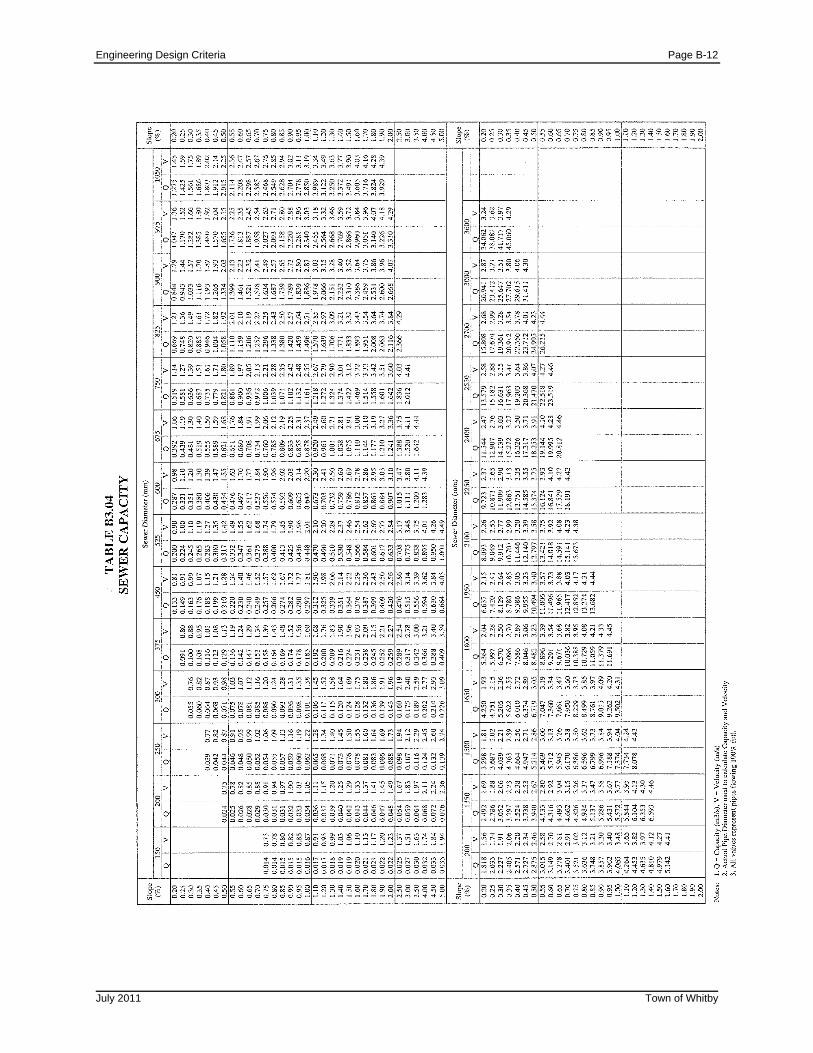
B3.04 Pipe Capacity
Manning's Formula shall be used to compute the capacity of storm sewers such that Qpeak flow < 0.8 Qpipe flowing full. For urbanized residential areas, a 15 minute entry time shall be used at the upstream end of the system. For urbanized commercial and industrial areas a 5 minute entry time shall be used. In the existing downtown core area, a 10 minute entry time shall be used. If another time is more appropriate, this may be proposed to the Director of Public Works, who shall make a final determination. Refer to Table B3.04 for Discharge and Velocity Pipe Capacity Charts. Critical Slope criteria shall be met such that Qpeak flow < Q at Sc where Sc is critical slope determined by the formula,
Sc = 9/ (D1/3) x (n/0.013)2 D= pipe diameter in mm.
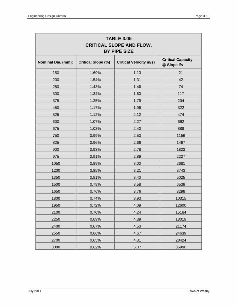
Adjustments to design pipe slope and/or diameter shall be made, if necessary, in order to satisfy this criteria, refer to Table 3.05. 100 Year Hydraulic Grade Line calculations shall be performed and adjustments to the five (5) year design pipe slope and/or diameter shall be made, if necessary, in order to satisfy the criteria that all underside of basement slab elevations will be a minimum of 0.50 m above the 100 year hydraulic grade line. While it is recognized that storm sewers and catchbasin spacing designed using the Town’s criteria may not capture the 100 year event, the onus is on the consultant to demonstrate the actual flow capture within the proposed storm sewer system using the Town’s 100 year design event. Alternatively, the 100 year design flow can be assumed to be captured. These flows shall then be used in the HGL calculations. Inlet Control Devices (ICD’s) will be considered to limit the flows into the storm sewer system if necessary. The starting elevation for the HGL calculation shall be the higher of: the 100 year water surface elevation within the receiving system (downstream SWM Pond, floodplain, etc.) or the obvert of the outlet pipe from the system. The HGL is to be plotted on all plan and profile drawings and calculations provided.
Where external drainage is captured, the peak flow used on the storm sewer design sheet shall be the maximum peak flow for the combined theoretical hydrographs for the external and internal system. External entry time and contributing area for the peak flow shall be calculated using industry standard equations (i.e. Uplands, Airport or Bransby Williams equations for instance). The minimum slope for storm sewers shall be 0.5%. Slopes less than this must be approved by the Director of Public Works.
Engineering Design Criteria Page B-12
July 2011 Town of Whitby
Engineering Design Criteria Page B-13
TABLE 3.05
CRITICAL SLOPE AND FLOW, BY PIPE SIZE
Nominal Dia. (mm): Critical Slope (%) Critical Velocity m/s) Critical Capacity @ Slope l/s
150 1.69% 1.13 21
200 1.54% 1.31 42
250 1.43% 1.46 74
300 1.34% 1.60 117
375 1.25% 1.79 204
450 1.17% 1.96 322
525 1.12% 2.12 474
600 1.07% 2.27 662
675 1.03% 2.40 888
750 0.99% 2.53 1156
825 0.96% 2.66 1467
900 0.93% 2.78 1823
975 0.91% 2.89 2227
1050 0.89% 3.00 2681
1200 0.85% 3.21 3743
1350 0.81% 3.40 5025
1500 0.79% 3.58 6539
1650 0.76% 3.76 8298
1800 0.74% 3.93 10315
1950 0.72% 4.09 12600
2100 0.70% 4.24 15164
2250 0.69% 4.39 18019
2400 0.67% 4.53 21174
2550 0.66% 4.67 24639
2700 0.65% 4.81 28424
3000 0.62% 5.07 36990
July 2011 Town of Whitby
Engineering Design Criteria Page B-14
July 2011 Town of Whitby
B3.05 Roughness Coefficients
The roughness coefficients to be used for storm sewer pipes shall be:
(a) Concrete pipe: n = 0.013 for all sizes of pipes.
(b) Vitrified Tile: n = 0.013 for all sizes of pipes.
(c) Polyvinyl Chloride (PVC) pipe: n = 0.013 for all sizes of pipe.
(d) Corrugated Metal: According to manufacturers specifications.
B3.06 Velocity
The velocity in storm sewers shall be limited to a minimum value of 0.75 m/s and a maximum value of 4.5m/s.
B3.07 Minimum Sizes of Pipe
Sewer Mains - 300 mm Catchbasin Connections - Single Catchbasin - 250 mm
- Double Catchbasin - 300 mm
- Rear Yard Catchbasin Leads - 300 mm
B3.08 Minimum Depth
The depth as measured from the final centerline road elevation to the sewer invert shall be a minimum of 1.8 m or sufficient to provide a suitable outlet for the building foundation weeping tile with provision for the 100 year hydraulic grade line to be a minimum of 0.5 m below underside of basement floor elevations. The minimum cover to the pipe obvert shall be 1.2 m.
B3.09 Maintenance Holes
(a) Maintenance holes shall be provided at each change in alignment, grade, material and at all junctions.
(b) Maintenance holes shall be spaced at a maximum of 100 m; for sewers
1200 mm diameter and greater the spacing may be increased to 150 m.
(c) Type and size of maintenance hole shall be specified on the profiles and a detail of the benching to be shown on the plan portion of the drawing for cases where the benching differs from the Town of Whitby Standard Drawing No. 100.
Engineering Design Criteria Page B-15
July 2011 Town of Whitby
(d) Maximum pipe sizes for typical inlet and outlet pipe configuration for precast
maintenance holes of 1200, 1500, 1800, and 2400 mm diameter are shown on Town of Whitby Standard Drawing No.100.
(e) The maximum change in direction of flow in maintenance holes for sewer
sizes 1200 mm diameter and over shall be 45°.
(f) The change in direction of flow in any maintenance hole will not be permitted at acute interior angles.
(g) Maintenance holes shall be designed with sufficient drop to compensate for
energy loss due to changes in direction, velocity and depth of flow. The minimum drop across the maintenance hole for all straight runs – 30 mm, all other – 60 mm.
(h) Hydraulic calculations shall be submitted if requested. Wherever possible,
the velocity change across a maintenance hole should not exceed 0.6 m/s. Where the difference in invert elevation between the inlet and outlet pipes exceeds 0.9 m, a drop structure shall be provided as detailed in Town of Whitby Standard Drawing No. 101.
(i) In any maintenance hole the inlet pipe obverts shall be higher than or equal
to the obvert of the outlet pipe.
(j) All maintenance holes shall be benched to the spring line of all pipes.
(k) All benching inside maintenance holes shall be a minimum of 225 mm in width.
(l) No maintenance hole shall be located closer than 1.5 m from any curb face
or other utility to outside of barrel of 1200 mm diameter chimney portion.
(m) Although the Town of Whitby Standard Drawings provide details for maintenance holes up to certain maximum depths; the Consulting Engineer shall analyze individually each application of the standards related to soil conditions, loading and other pertinent factors to determine structure stability. In all cases where the standards are not applicable, maintenance holes must be individually designed and detailed.
(n) When any horizontal dimension of a maintenance hole exceeds 3.6 m, the
maintenance hole must be individually designed and sufficiently detailed to permit poured in place construction.
(o) A minimum clearance of 0.2 m shall be provided between the outside of all
pipe barrels at all points of pipe crossings. Concrete encasement may be required.
(p) Safety gratings shall be required on all maintenance holes when their depth
exceeds 5.0 m. Maximum spacing between safety grates is 5.0 m as per OPSD 404.020. Platforms to be installed at the half way point.

Engineering Design Criteria Page B-16
July 2011 Town of Whitby
B3.10 Catchbasins
(a) Standard catchbasin designs are detailed in the Ontario Provincial Standard Drawings OPSD 705.010, 705.020 and grate 400.010 for roads and OPSD 705.030 and grate 400.020 for rear yards.
(b) Special catchbasins and inlet structures shall be fully designed and detailed.
(c) Catchbasins shall be selected, located and spaced in accordance with the
conditions of design. The design of catchbasin location and type shall take into consideration the contributing drainage areas, lot grades, pavement widths, road grades and intersection locations. The acceptable spacing requirements shall be as follows:
Maximum Spacing Maximum Spacing
Pavement Width 4% Grade or Less Greater than 4%
8.5 m 90 m 60 m 10.0 m 80 m 55 m 15.0 m 60 m 40 m
The catchbasin spacing may be altered for grades over 4.0% for special cases by using side inlet catchbasins or special grates. Double catchbasins are required where drainage is received from more than one direction.
(d) Catchbasins shall be located immediately upstream of sidewalk crossings at intersections and upstream of all pedestrian crossings. Where possible, catchbasins shall not be located in driveway curb depressions.
(e) Catchbasin grate and connection shall provide for the expected maximum
minor system (5 year return period storm) flow.
For Single Catchbasins- the connection shall not be less than 250 mm diameter pipe laid at 1.0% minimum grade.
For Double Catchbasins- the connection shall not be less than 300 mm
diameter pipe laid at 1.0% minimum grade.
(f) Catchbasin leads shall be installed in accordance with Town of Whitby Standard Drawing No. 107. Rear yard catchbasin leads shall be installed entirely on one lot offset 0.5 m from the lot line. A 3.0 m wide easement centered on the lot line and containing the lead and catchbasin shall be dedicated to the Town of Whitby. Concrete encasement (15-20 MPa) shall be utilized as per Town of Whitby Standard Drawing No. 107.10.
(g) Road subdrain as per Town of Whitby Standard Drawings No. 108 and No.
109 shall be connected to catchbasins as outlined in these drawings.
Engineering Design Criteria Page B-17
July 2011 Town of Whitby
(h) Not withstanding any requirements for spacing of inlets, the maximum
impervious area calculated by multiplying the area times the runoff coefficient to be connected to a single catchbasin inlet shall be 0.18 impervious hectares (example 0.2 ha at 0.9 runoff coefficient). Similarly, the maximum impervious area for a double catchbasin shall be 0.36 impervious hectares.
B3.11 Pipe
(a) Pipe bedding and class shall be designed to suit loading conditions. The class or strength, size and bedding shall be shown on the profiles.
(b) All storm sewers shall be located as shown on the appropriate road cross-
section standard. Refer to Town of Whitby Standard Drawing No’s 400, 401, 401.10, 402 and 403.
(c) All storm sewers shall be laid in a straight line between maintenance holes
except where radius pipe is permitted (see (e) below).
(d) The pipe size shall not decrease from a larger size upstream to a smaller size downstream regardless of any increase in grade. A decrease in pipe size from upstream to downstream will only be permitted where the larger pipe is designed for storm water detention.
(e) Radius pipe will be permitted in sizes 1050 mm diameter and over. The
minimum radius shall be in accordance with the pipe manufacturer. Radius pipe sections shall be designed with at least one maintenance hole at one end of the section.
B3.12 Inlet and Outfall Structures
(a) Inlet and outfall structures, including head walls, shall be fully designed and submitted in detail. Where possible, structures shall conform to applicable Ontario Provincial Standard Drawings. In each case, existing topography should be shown as well as the protective works necessary to prevent erosion of the site around the structures, including erosion from the outfall flows.
(b) In general, inlet grates shall consist of inclined parallel bars or rods set in a
plane sloping approximately 45° away from and in the direction of the flow. Outfall grates shall consist of horizontal bars or rods. Spacing of bars or rods shall not exceed 150 mm clear. All metal parts shall be hot dip galvanized or stainless steel. When the vertical face of any structure exceeds 0.60 m high it shall be fitted with a handrail in accordance with Town of Whitby Standard Drawing No. 103.
B3.13 Storm Drain Connections B3.13.1 General
(a) Storm service connections shall be installed to service each lot, block and unit in the subdivision and shall extend 1.5 m to 3.0 m inside the property line.
Engineering Design Criteria Page B-18
July 2011 Town of Whitby
(b) The services shall be installed in accordance with the Town of Whitby
Standard Drawings.
(c) Service connections shall not, in general, be made to a trunk sewer.
(d) Risers shall be constructed when the invert of a sewer exceeds 4.5 m in depth. No riser shall exceed 3.0 m in height unless approved by the Director of Public Works.
(e) Front roof leaders shall connect directly to the storm system. Single family
and semi-detached rear roof leaders must discharge to the ground surface via a splash pad. Street townhouses roof leaders shall connect to the storm system unless otherwise directed. Refer to Town of Whitby standard drawing No.106.10 for storm drain under basement floor if needed.
(f) PVC pipe for storm drain connections is to be white in colour.
B3.13.2 Single Family, Semi-detached and Street Townhouses
(a) Storm drain connections shall be designed in accordance with Town of Whitby Standard Drawings No’s. 104, 105 and 106. The designer shall confirm that pipe loading conditions and soil conditions are suitable for standard strength pipe and standard bedding details.
(b) The connection to the main sewer shall be made with an approved
manufacturer's tee for main sewer sizes up to and including 375 mm diameter and in accordance with the details on Town of Whitby Standard Drawings for larger sizes.
(c) Storm connections for Single Family, Semi-Detached & Street Townhouse
units shall be PVC SDR 28 with a minimum 2.0% grade. A 50mm x 100 mm wooden marker shall be placed at the end of the connection and shall have the top 600 mm painted green & above the lot grade
(d) Storm connections for Single Family, Semi-Detached & Street Townhouse
Units shall be PVC SDR 28 with a minimum 2.0% grade. A 50 mm x 100 mm wooden marker shall be placed at the end of the connection and shall have the top 600 mm painted green and above the lot grade.
(e) The minimum depth at the street line shall be 1.8 m and the maximum depth
3.1 m, measured from the final centerline road elevation. Risers shall be used when the invert depth of the sewer main exceeds 4.5 m. Risers shall not exceed 3.0 m in height without approval of the Director of Public Works.
(f) Service connections shall not connect into a catchbasin, or maintenance
hole.
(g) Joints and bedding for connections shall be equivalent to joints and bedding on the main sewer.
Engineering Design Criteria Page B-19
July 2011 Town of Whitby
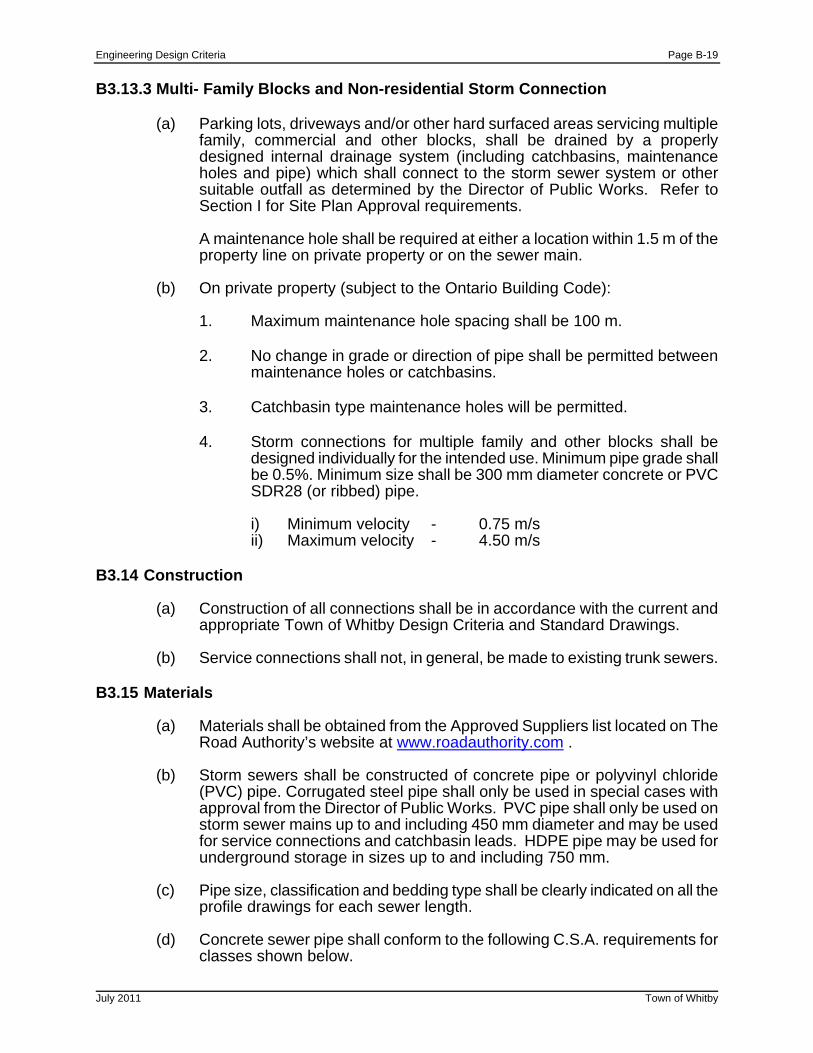
B3.13.3 Multi- Family Blocks and Non-residential Storm Connection
(a) Parking lots, driveways and/or other hard surfaced areas servicing multiple family, commercial and other blocks, shall be drained by a properly designed internal drainage system (including catchbasins, maintenance holes and pipe) which shall connect to the storm sewer system or other suitable outfall as determined by the Director of Public Works. Refer to Section I for Site Plan Approval requirements.
A maintenance hole shall be required at either a location within 1.5 m of the property line on private property or on the sewer main.
(b) On private property (subject to the Ontario Building Code):
1. Maximum maintenance hole spacing shall be 100 m.
2. No change in grade or direction of pipe shall be permitted between
maintenance holes or catchbasins.
3. Catchbasin type maintenance holes will be permitted.
4. Storm connections for multiple family and other blocks shall be designed individually for the intended use. Minimum pipe grade shall be 0.5%. Minimum size shall be 300 mm diameter concrete or PVC SDR28 (or ribbed) pipe.
i) Minimum velocity - 0.75 m/s ii) Maximum velocity - 4.50 m/s
B3.14 Construction
(a) Construction of all connections shall be in accordance with the current and appropriate Town of Whitby Design Criteria and Standard Drawings.
(b) Service connections shall not, in general, be made to existing trunk sewers.
B3.15 Materials
(a) Materials shall be obtained from the Approved Suppliers list located on The Road Authority’s website at www.roadauthority.com .
(b) Storm sewers shall be constructed of concrete pipe or polyvinyl chloride
(PVC) pipe. Corrugated steel pipe shall only be used in special cases with approval from the Director of Public Works. PVC pipe shall only be used on storm sewer mains up to and including 450 mm diameter and may be used for service connections and catchbasin leads. HDPE pipe may be used for underground storage in sizes up to and including 750 mm.
(c) Pipe size, classification and bedding type shall be clearly indicated on all the
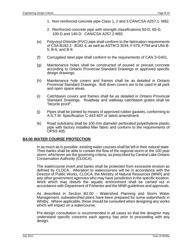
profile drawings for each sewer length. (d) Concrete sewer pipe shall conform to the following C.S.A. requirements for
classes shown below.
Engineering Design Criteria Page B-20
July 2011 Town of Whitby
1. Non-reinforced concrete pipe Class 1, 2 and 3 CAN/CSA A257.1- M92.
2. Reinforced concrete pipe with strength classifications 50-D, 65-D, 100-D and 140-D. CAN/CSA A257.2-M92.
(e) Polyvinyl Chloride (PVC) pipe shall conform to the fabrication requirements
of CSA B182.2 - B182.4, as well as ASTM D 3034, F 679, F794 and UNI-B-5, B-6, and B-9.
(f) Corrugated steel pipe shall conform to the requirements of CAN 3-G401. (g) Maintenance holes shall be constructed of poured or precast concrete
according to Ontario Provincial Standard Drawings or approved specific design drawings.
(h) Maintenance hole covers and frames shall be as detailed in Ontario
Provincial Standard Drawings. Bolt down covers are to be used in all park and open space areas.
(i) Catchbasin covers and frames shall be as detailed in Ontario Provincial
Standard Drawings. Roadway and walkway catchbasin grates shall be "bicycle proof".
(j) Pipes shall be jointed by means of approved rubber gaskets, conforming to
A.S.T.M. Specification C-443-60T or latest amendment.
(k) Road subdrains shall be 100 mm diameter perforated polyethylene plastic pipe with factory installed filter fabric and conform to the requirements of OPSS 405.
B4.00 WATER COURSE PROTECTION
In as much as is possible, existing water courses shall be left in their natural state. Their banks shall be able to contain the flow of the regional storm or the 100 year storm, whichever are the governing criteria, as prescribed by Central Lake Ontario Conservation Authority (CLOCA).
The watercourse invert and banks shall be protected from excessive erosion as defined by CLOCA. Alteration to watercourses will be in accordance with the Director of Public Works, CLOCA, the Ministry of Natural Resources (MNR) and any other government agencies who may have jurisdiction in the specific location. Work which may disturb the aquatic environment shall be carried out in accordance with Department of Fisheries and the MNR guidelines and approvals.
As described in Section B2.00 - Watershed Planning and Storm Water Management, subwatershed plans have been prepared for some watersheds in Whitby. Where applicable, these should be consulted when designing any works which will impact on a watercourse. Pre-design consultation is recommended in all cases so that the designer may understand specific concerns each agency has prior to proceeding with any design.
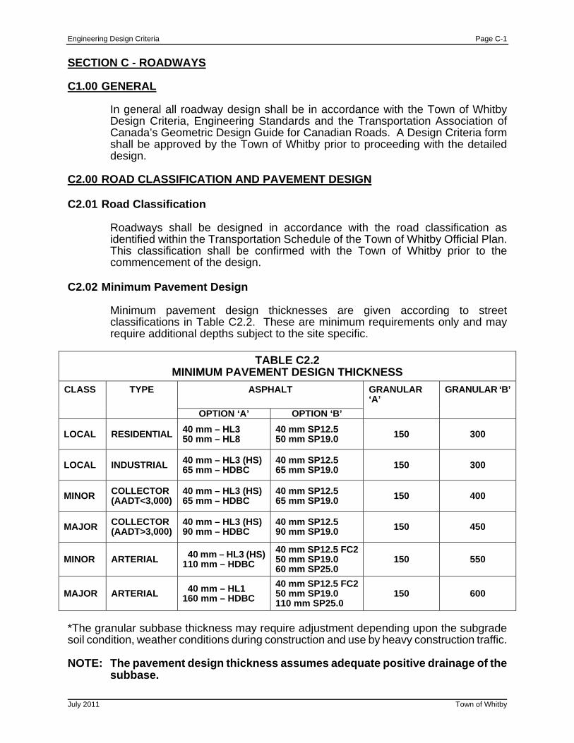
Engineering Design Criteria Page C-1
July 2011 Town of Whitby
SECTION C - ROADWAYS C1.00 GENERAL
In general all roadway design shall be in accordance with the Town of Whitby Design Criteria, Engineering Standards and the Transportation Association of Canada’s Geometric Design Guide for Canadian Roads. A Design Criteria form shall be approved by the Town of Whitby prior to proceeding with the detailed design.
C2.00 ROAD CLASSIFICATION AND PAVEMENT DESIGN C2.01 Road Classification
Roadways shall be designed in accordance with the road classification as identified within the Transportation Schedule of the Town of Whitby Official Plan. This classification shall be confirmed with the Town of Whitby prior to the commencement of the design.
C2.02 Minimum Pavement Design
Minimum pavement design thicknesses are given according to street classifications in Table C2.2. These are minimum requirements only and may require additional depths subject to the site specific.
TABLE C2.2
MINIMUM PAVEMENT DESIGN THICKNESS
ASPHALT CLASS TYPE
OPTION ‘A’ OPTION ‘B’
GRANULAR ‘A’
GRANULAR ‘B’
LOCAL RESIDENTIAL 40 mm – HL3 50 mm – HL8
40 mm SP12.5 50 mm SP19.0 150 300
LOCAL INDUSTRIAL 40 mm – HL3 (HS) 65 mm – HDBC
40 mm SP12.5 65 mm SP19.0 150 300
MINOR COLLECTOR (AADT<3,000)
40 mm – HL3 (HS) 65 mm – HDBC
40 mm SP12.5 65 mm SP19.0 150 400
MAJOR COLLECTOR (AADT>3,000)
40 mm – HL3 (HS) 90 mm – HDBC
40 mm SP12.5 90 mm SP19.0 150 450
MINOR ARTERIAL 40 mm – HL3 (HS)110 mm – HDBC
40 mm SP12.5 FC250 mm SP19.0 60 mm SP25.0
150 550
MAJOR ARTERIAL 40 mm – HL1 160 mm – HDBC
40 mm SP12.5 FC250 mm SP19.0 110 mm SP25.0
150 600
*The granular subbase thickness may require adjustment depending upon the subgrade soil condition, weather conditions during construction and use by heavy construction traffic. NOTE: The pavement design thickness assumes adequate positive drainage of the
subbase.
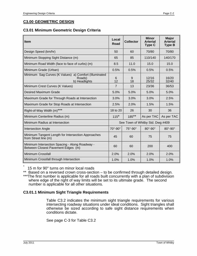
Engineering Design Criteria Page C-2
July 2011 Town of Whitby
C3.00 GEOMETRIC DESIGN C3.01 Minimum Geometric Design Criteria
Item Local Road
Collector Minor
Arterial Type C
Major Arterial Type B
Design Speed (km/hr) 50 60 70/80 70/80
Minimum Stopping Sight Distance (m) 65 85 110/140 140/170
Minimum Road Width (face to face of curbs) (m) 8.5 11.0 15.0 15.0
Minimum Grade (Urban) 0.5% 0.5% 0.5% 0.5%
Minimum Sag Curves (K Values) a) Comfort (Illuminated Roads) b) Headlights
6 12
9 18
12/16 25/32
16/20 32/40
Minimum Crest Curves (K Values) 7 13 23/36 36/53
Desired Maximum Grade 5.0% 5.0% 5.0% 5.0%
Maximum Grade for Through Roads at Intersection 3.0% 3.0% 3.0% 2.5%
Maximum Grade for Stop Roads at Intersection 2.5% 2.0% 1.5% 1.5%
Right-of-Way Width (m)*** 18 to 20 26 30 36
Minimum Centerline Radius (m) 115* 185** As per TAC As per TAC
Minimum Radius at Intersection See Town of Whitby Std. Dwg #409
Intersection Angle 70°-90° 75°-90° 80°-90° 80°-90°
Minimum Tangent Length for Intersection Approaches from Street line (m) 45 60 75 75
Minimum Intersection Spacing - Along Roadway - Between Closest Pavement Edges (m) 60 60 200 400
Minimum Crossfall 2.0% 2.0% 2.0% 2.0%
Minimum Crossfall through Intersection 1.0% 1.0% 1.0% 1.0%
* 15 m for 90° turns on minor local roads ** Based on a reversed crown cross-section – to be confirmed through detailed design. ***The first number is applicable for all roads built concurrently with a plan of subdivision where edge of the right of way limits will be set to its ultimate grade. The second number is applicable for all other situations. C3.01.1 Minimum Sight Triangle Requirements
Table C3.2 indicates the minimum sight triangle requirements for various intersecting roadway situations under ideal conditions. Sight triangles shall otherwise be sized according to safe sight distance requirements when conditions dictate. See page C-3 for Table C3.2
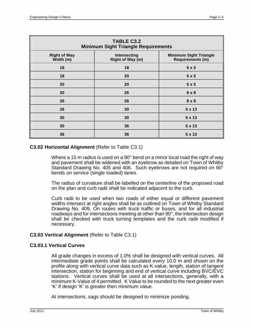
Engineering Design Criteria Page C-3
July 2011 Town of Whitby
TABLE C3.2 Minimum Sight Triangle Requirements
Right of Way
Width (m)
Intersecting
Right of Way (m)
Minimum Sight Triangle
Requirements (m)
18
18
5 x 5
18
20
5 x 5
20
20
5 x 5
20
26
8 x 8
26
26
8 x 8
26
30
5 x 13
30
30
5 x 13
30
36
5 x 13
36
36
5 x 13
C3.02 Horizontal Alignment (Refer to Table C3.1)
Where a 15 m radius is used on a 90° bend on a minor local road the right of way and pavement shall be widened with an eyebrow as detailed on Town of Whitby Standard Drawing No. 405 and 406. Such eyebrows are not required on 90° bends on service (single loaded) lanes.
The radius of curvature shall be labelled on the centerline of the proposed road on the plan and curb radii shall be indicated adjacent to the curb.
Curb radii to be used when two roads of either equal or different pavement widths intersect at right angles shall be as outlined on Town of Whitby Standard Drawing No. 409. On routes with truck traffic or buses, and for all industrial roadways and for intersections meeting at other than 90°, the intersection design shall be checked with truck turning templates and the curb radii modified if necessary.
C3.03 Vertical Alignment (Refer to Table C3.1) C3.03.1 Vertical Curves
All grade changes in excess of 1.0% shall be designed with vertical curves. All intermediate grade points shall be calculated every 10.0 m and shown on the profile along with vertical curve data such as K-value, length, station of tangent intersection, station for beginning and end of vertical curve including BVC/EVC stations. Vertical curves shall be used at all intersections, generally, with a minimum K-Value of 4 permitted. K Value to be rounded to the next greater even ‘K’ if design ‘K’ is greater then minimum value. At intersections, sags should be designed to minimize ponding.
Engineering Design Criteria Page C-4
July 2011 Town of Whitby
C3.03.2 Minimum/Maximum Grades
Vertical alignment requirements are shown in Table C3.1. Minimum grades are to be avoided in superelevated urban roadways. Minimum gutter grade of 1.0% are to be maintained.
C3.03.3 Minimum Gutter Grades
The minimum gutter grade shall be 0.5% except for bulbs and turning circles where it shall be 1.0%. Where 1.0% cannot be achieved in turning circles, catchbasins shall be placed at the direction of the Public Works Department.
C3.04 Industrial Roads
The geometric criteria for industrial roads shall be determined on a site specific basis with approval required from the Director of Public Works. Generally, local industrial roads shall have a 10 m pavement width (face of curb to face of curb), a 20 m R.O.W. with utilities located as detailed on Town of Whitby Standard Drawing No. 400.
Industrial road design must take into account specific turning and vertical alignment requirements of trucks and buses. For example, minimum sag curves shall be K=8.
C3.05 Roadside Ditches All new urban roads shall be curb and gutter unless approved by the Director of Public Works.
Rural roadside ditches shall be designed with 3:1 front slope and minimum 2:1 backslope (3:1 desirable). Ditch inverts shall be minimum 150 mm below the granular/sub-grade interface where it daylights into the ditch unless an invert subdrain is designed to pick up subgrade drainage. Rural roads shall conform to Town of Whitby Standard Drawing No. 403 unless otherwise approved by the Director of Public Works.
Desirable minimum longitudinal ditch grade shall be 1.0% with absolute minimum being 0.3%. Ditch grades greater than 3.0% shall have staked sod protection. Ditches greater than 5.0% shall have hand laid rip rap protection.
C3.06 Subdivision Emergency Access 1. The following criteria shall be used for the approval of urban subdivision developments: (l) Cul de sacs should not exceed 230 metres in length. (m) The entrance portion to P-Loops and B-Loops shall not exceed 90 metres. (n) Where the circumference of a P-Loop (or one half of a B-Loop) exceeds
490 metres, the entrance portion shall have a minimum road width of 12 metres, exclusive of any medium required or incorporated.
Engineering Design Criteria Page C-5
July 2011 Town of Whitby
(o) The maximum circumference of a P-Loop (or one half of a B-Loop), or any
combination of street pattern, shall not exceed 700 metres and (p) For the purpose of this policy it is assumed that in the case of items (c), (d)
and (e) that any P-Loop or B- Loop shall include a service lane adjacent to a collector or arterial road. Where a service lane is not included in the design of a P-Loop or B-Loop, a permanent walkway providing emergency access shall be required where a P-Loop or B-Loop exceeds 430 metres, subject to the following minimum design standards.
2. Where the limits of the items in Section 1 of this policy procedure are exceeded, a second means of access shall be provided. 3. Where an emergency access walkway or a temporary access is to be installed then the following design criteria shall be used:
Minimum width of 4.0 metres; Maximum slope of 8.0%; 12.0 metres minimum centerline turning radius; 5.0 metre minimum overhead clearance from grade; Asphalt or other permanent surface; Barrier consisting of bollards and chain or other acceptable measures;
and, Adherence to the Ontario Building Code.
4. Prior to the issuance of a building permit the emergency access will be required to be fully constructed and operational.
NOTE: 1. Circumference is measure at centre line of road. 2. Road width – face of curb to face of curb.
C4.00 ROAD PAVEMENT DESIGN C4.01 Geotechnical Report
Pavement design for local, collector and arterial roads will be considered on an individual basis. Minimum pavement design thickness for different road classifications are shown on Table C2.2. The composition and construction thickness of the road pavement shall be designed based upon the following factors:
(a) Mechanical analysis of the sub-grade soil;
(b) Drainage;
(c) Frost susceptibility;
(d) Future volume and class of traffic expected to use the pavement; and,
(e) Construction loading considerations.
Engineering Design Criteria Page C-6
July 2011 Town of Whitby
Sub-grade samples for mechanical analysis laboratory testing shall be taken at a maximum of 50 m intervals along all road alignments and at any locations judged to be lower in bearing capacity. California Bearing Ratio (C.B.R.) tests shall be performed for each representative soils type. All tests must be conducted by a qualified soils consultant. Copies of all tests and the road design proposed by the soils consultant shall be submitted for the approval of the Director of Public Works.
Where the construction will involve trenching for installation of sewers and water mains, the soils report shall comment on trenching, pipe bedding, cover, backfill and compaction requirements. It shall provide recommendations with respect to construction methods to be employed to reduce risk of settlement occurring.
For reconstruction projects, the report shall include analysis of existing granular and asphalt materials and include recommendations regarding reuse.
C4.02 Splining Details for Eyebrows and Bulbs
All eyebrows and cul-de-sacs shall be detailed at a larger scale than the road plan. The details shall show crossfall and gutter, crown and other grades sufficient to determine that the road will properly drain and to be used as a basis for layout.
The minimum gutter grade shall be 1.0% maintained along the flow line of all gutters around eyebrows and cul-de-sac bulbs. On reconstruction projects or when constraints prevent achieving 1.0% grade, consideration should be given to installing catchbasins.
C4.04 Temporary Turning Circles
Temporary turning circles are required where a road will be continued for future phasing of development, but currently dead ends. Land easements within the subdivision must be dedicated to the Town of Whitby to facilitate installation of temporary turning circles.
Requirements - R.O.W. radius as dictated by temporary grading requirements
- Curb radius 13.25 m
Permanent sidewalk shall terminate short of the temporary turning circle with a temporary asphalt ramp connecting the sidewalk to the bulb.
Permanent stage 1 of 2 stage curb and gutter shall be installed through the temporary bulb, and the permanent portion of roadway paved with normal crown elevation and crossfall. Temporary asphalt curb or concrete barrier curb (no gutter) may be utilized for the bulb portion.
C4.05 Intersections
Curb radii requirements for intersecting pavements are shown on Town of Whitby Standard Drawing No. 409. At the intersection of two roads, the transition of the minor classification road shall not interfere with the normal cross-fall of the major road.
Engineering Design Criteria Page C-7
July 2011 Town of Whitby
A 1.0% to 2.0% backfall shall be provided on all road profiles. This requirement will not necessarily require the use of a double catchbasin. A larger scale splining detail showing crossfall, gutter, crown and other grades, sufficient to determine that the intersection will drain properly and sufficient for layout, shall be provided. Catchbasins shall generally be located upstream of pedestrian crosswalks. Intersection design for Collector/Collector, Collector/Arterial and Arterial/Arterial shall be designed according to TAC Section 2.3.2.3, Vertical Alignment and Cross-Slope.
C4.06 Location of Utilities
The utility locations within the road allowance shall be as detailed in the Town of Whitby Standard Drawings No. 400 to 404.30. Master Utility Plans showing all proposed utility locations must be prepared and shall be submitted to the Town of Whitby Public Works Department for approval. A 1.0m minimum clearance is required between edge of driveways and any above ground utility excluding fire hydrants.
C4.07 Locations of Community Super Mailboxes
Community mail boxes shall be placed according to the Canada Post Corporation requirements and Standard Drawing No. 308. Design locations for super mail boxes should incorporate factors such as pedestrian safety, driveway locations, traffic flow and aesthetics. Community mail box locations shall be indicated on the Master Utility Plans.
C5.00 BOULEVARDS, SIDEWALKS AND WALKWAYS C5.01 Sidewalks
Sidewalks are generally required on at least one side of all local streets and on both sides of collector and arterial roadways. Local streets may require sidewalks on both sides of the street when located near schools, parks, churches, hospitals, etc. The Director of Public Works will advise when sidewalks are required on both sides.
All sidewalks are to be designed in accordance with the Town of Whitby Standard Drawing No. 208 and shall be installed at locations shown on the typical road cross-sections.
At all driveway locations the sidewalk thickness shall be increased to 175mm for both residential and commercial driveways. On commercial driveways, a 150mm x 150mm wire mesh shall also be placed in accordance with Town of Whitby Standard Drawing No. 208.
A curb keyway shall be incorporated into the curb where sidewalks are constructed adjacent to curbs as detailed on Town of Whitby Standard Drawing No. 206 and OPSD 600.404.
Requirements for temporary asphalt sidewalks are shown in the Town of Whitby Standard Drawing No. 210.
Engineering Design Criteria Page C-8
July 2011 Town of Whitby
C5.02 Boulevards
Boulevards are to be graded according to the Town of Whitby Standard Drawing No. 208. On new construction the grade of the boulevard shall be constant from the back of the curb to the street limit or sidewalk.
Where required boulevards will be constructed to incorporate tree well and grate according to the Town of Whitby Standard Drawings No. 212 and 213. Brick Pavers are to be installed as per Town of Whitby Standard Drawing No. 211.
C5.03 Walkways
Walkways shall be constructed in accordance with Town of Whitby Standard Drawing No. 209 to promote proper circulation of pedestrian traffic and also to provide an overland flow route for storm flows greater than the pipe capacity.
C5.04 Multi-use Pathways
Multi-use Asphalt Pathways shall be constructed in accordance with Town of Whitby Standard Drawing No. 214.
C6.00 DRIVEWAYS AND ENTRANCES C6.01 Driveways C6.01.1 Residential Driveways
Where paved driveways are installed within either the public right of way or on private property, between the curb and garage floor the top of driveway shall be flush with curb, sidewalk and garage floor. The minimum depth for residential driveway shall be: (a) Residential Driveways
50 mm hot-mix, hot-laid asphalt HL3A to be placed in one lift only. 150 mm crusher run limestone or Granular "A".
The maximum design grade for an access driveway shall be 6.0%. Maximum as-built grade shall be 8.0%. The minimum grade shall be 2.0%. Refer to Town of Whitby Standard Drawing No.’s 304 and 305 for driveway profile and layout.
Engineering Design Criteria Page C-9
July 2011 Town of Whitby
C6.01.2 Industrial, Commercial and Institutional Driveways
Paved driveway entrances are required between the curb and sidewalk. The following are minimum depth requirements:
(a) Light Industrial, Commercial and Apartment Driveways
50 mm hot mix, hot laid HL3 to be placed in one lift. 50 mm hot mix, hot laid HL8 to be placed in one lift. 200 mm crusher run limestone; or 150 mm Granular "A"; and 225 mm Granular ‘B’.
(b) Heavy Industrial Driveways
50 mm hot mix, hot laid HL3 to be placed in one lift. 75 mm hot mix, hot laid HL8. 300 mm crusher run limestone or 150 mm Granular "A"; and 300 mm Granular "B"
Equivalent depths of “deep” strength asphalt will be permitted as a substitute for the pavement specified above provided frost susceptibility is addressed in the design.
C6.01.3 Rural Driveways
On rural roads where sidewalks are not required, driveway entrances are to be minimum 150 mm of Granular ‘A’ or 19 mm crusher run limestone.
C6.02 Concrete Curb and Gutter C6.02.1 Curb Standard - Development
Full height curbs and gutters as per Town of Whitby Standard Drawing No. 206 are required on both sides of all urban streets and roads with pavement width of 10.0 m or greater. Local urban roads with pavement widths of 8.5 m require curb and gutter as per OPSD Drawing No. 600.04 and may be of two stage construction as per Town of Whitby Standard Drawing No. 206. For 15.0 m service lanes, full height curb and gutter shall be utilized on the side of the roadway adjacent to the higher order road. Any deviation from these standards must be approved by the Director of Public Works.
Barrier curb as per OPSD Drawing No. 600.110 may be used for the bulb portion of temporary turning circles where a gutter is not required and for site plans associated with building permits as outlined Section I.
C6.02.2 Curb Standard - Reconstruction Concrete curb and gutter as per OPSD Drawing No. 600.040 to be used on Reconstruction Capital Projects unless approved otherwise by the Director of Public Works. Concrete curb and gutter on the high side of superelevated urban roadways to be according to OPSD 600.040 Tangent.
Engineering Design Criteria Page C-10
July 2011 Town of Whitby
C6.02.3 Driveway Entrances
The width of curb depression for residential driveways shall be as detailed on Town of Whitby Standard Drawing No. 305. The width of curb depression for apartment, commercial and industrial driveways shall take into account the basic width of the driveway and the radius of curvature as further outlined below. Where mutual driveways are constructed between two adjoining properties, the curb depression shall be continuous. Driveways on cul-de-sacs shall be in accordance with Town of Whitby Standard No. 411.
The radius of curvature from the road into apartment, commercial and industrial driveways shall be designed to accommodate the anticipated vehicular traffic without causing undue interference with the traffic flow on the street. The maximum curb radius shall be
(a) 7.5 m for apartment and residential block developments,
(b) 15.2 m for heavy industrial and commercial entrances off 2-lane roads and 4-lane roads.
Details for apartment, commercial and industrial entrances shall be shown on the plans.
All apartments, commercial and industrial driveways shall be provided with curb constructed in accordance with details as outlined on Town of Whitby Standard Drawing No. 410.
C7.00 ROADWAY CYCLING FACILITIES
Roadway Cycling Facilities should be incorporated in accordance with the “Town of Whitby Cycling and Leisure Trail Plan”. While this study has identified the preferred routes and facility types, confirmation is to be provided by the Public Works Department prior to implementation. This study has identified the following cycling facility types.
C7.01 Boulevard Multi-Use Paths
Boulevard multi-use paths are 3.0 m wide asphalt paved paths located within the road boulevard and are generally parallel to the road. These paths are separated from the road by a grassed or landscaped buffer. Refer to Town of Whitby Standard drawing No. 214. Due to safety issues associated with frequent driveways and side streets, boulevard multi-use paths should be implemented along roadways where driveways and site streets intersections are spaced at more than 300 m or more.
C7.02 Shared Use Lanes
These are traffic lanes marked with “shared use lane” pavement marking or “sharrows. They are recommended for low speed roadway (50kn/h or less) where there is insufficient pavement width for bike lanes. Bicycle symbols and double chevrons are provided every 200 m, and “share the road” signage at every 300 m.
Engineering Design Criteria Page C-11
July 2011 Town of Whitby
C7.03 Bike Lanes
Bike lanes on urban roadways (i.e. roads with curb and gutter) provide dedicated lanes for cyclists on higher speed/volume roads. Bike lanes are typically 1.5 m wide separated from traffic lanes by a 10 cm white solid line. Bicycle symbols and diamonds are provided at every 200 m, and “bike lane” signage at every 300 m.
C7.04 Paved Shoulders
Paved shoulders on rural roadways (i.e. roads with ditches) provide dedicated lanes for cyclists on higher speed/volume roads. Paved shoulders are typically 1.5 m wide separated from traffic lanes by two 10 cm white solid lines. Bicycle symbols and diamonds are provided at every 200 m, and “bike lane” signage at every 300 m.
C8.00 CONSTRUCTION
The construction of all roads in the Town of Whitby shall be in accordance with current Town of Whitby and Ontario Provincial Standard Drawings and Ontario Provincial Standard Specifications unless otherwise outlined in the contract drawings and specifications and approved by the Director of Public Works.
Engineering Design Criteria Page D-1
July 2011 Town of Whitby
SECTION D - LOT GRADING D1.00 GENERAL
The following lot grading design criteria shall be used in the preparation of all lot grading plans for new urban residential developments. These criteria will have to be implemented and/or exempted on a case by case basis when infill lot grading is undertaken or as part of a Municipal project.
Lot grading requirements for infill housing are detailed in Section D5.00. Grading design criteria includes proper surface drainage, overland flow routing, maximization of useable land area, preservation of existing trees, and consideration of impacts to abutting properties. All proposed sodded areas to be completely top soiled with 150 mm minimum uniform depth of topsoil and No. 1 nursery sod. (Isolated depth of 100 mm topsoil may be approved by the Director of Public Works)
D2.00 DESIGN D2.01 Lot Grading Design
The front yard of all lots shall be graded to drain towards the street. No front yard catchbasins shall be allowed in new developments.
All drainage shall be directed away from the houses in defined swales. Lot grading design shall conform to Town of Whitby Standard Drawings Section 300 Grading:
All lot surfaces shall be constructed to:
(a) 2.0% minimum lot grade; (b) 5.0% maximum lot grade, if maximum lot grade exceeds 5.0% and no
redesign alternative exists then the difference shall be made up with an embankment;
(c) maximum embankment slope 3:1, maximum embankment height 1.0 m, if embankment height exceeds 1.0 m then the difference shall be made up with a retaining wall;
(d) Retaining wall that is over 0.6 m in height requires free standing wall or fence that is a minimum of 1.2 m high; and,
(e) The maximum height of any wall/fence combination shall be 3.0 m. A minimum 0.6m maintenance strip shall be provided adjacent to that wall. Terraced walls shall have a horizontal separation equal to the height of the lower wall, no less than 1.0 m.
(f) Where adjacent to hazard lands, open spaces, storm water management blocks, parks or other public property the height of any wall should not exceed 0.6m.
All rear lot catchbasins and storm sewer leads shall be constructed on one lot. The centre of the catchbasins and storm sewer pipe shall be at least 0.5 m from the lot line.
Engineering Design Criteria Page D-2
July 2011 Town of Whitby
A 0.6 m strip shall be left undisturbed along the boundary of the subdivision next to adjacent properties unless grading is required to address drainage problems on adjacent properties. Such grading must be stipulated on the approved lot grading plan and ‘permission-to-enter’ agreements must be obtained for the affected property.
The lot grading plan shall include interim (prior to development) contours and ultimate grading details for all blocks of land shown on the registered plan. Prior to development all blocks are further subject to site plan agreement and approval by the Director of Public Works. Any blocks not developed by the time all other obligations of the Subdivision Agreement have been fulfilled, shall be graded to facilitate the drainage pattern shown on the lot grading plan prior to final assumption of the services.
D2.02 Drainage Swale Design
All rear yard drainage directed around houses shall be directed away from houses in defined swales which outlet at the curb or sidewalk. Driveways shall not be used as outlets for any swales.
Longitudinal slope to be 2.0% minimum.
Side slopes 3:1 maximum (if steeper than 3:1 side slopes are required, retaining walls shall be constructed to the satisfaction of the Town of Whitby). See Section E2.00 for Retaining Walls.
Rear and side yard swale depth 150mm minimum and 450 mm maximum
The maximum area permitted to discharge via a single swale directly onto a road allowance or into one rear yard catchbasin shall be from 8 rear yards or a maximum of 0.2 ha. All swales or ditches having a velocity exceeding 1.5 m/sec. will require erosion protection
Maximum length of swale between drainage outlets – 100 m. Drainage outlets shall be designed to outlet at the earliest opportunity, swale outlet locations shall be shown on the lot grading plans.
Grading shall be designed so that the maximum depth of ponding for blocked RYCB's shall be 0.4 m (i.e. an overflow route must be designed for each RYCB so that in the case of blockage, the depth of water over at the RYCB shall not exceed 0.4 m). This possible ponding shall not be within 0.1 m of any adjacent top of foundation or unprotected (no window well) window opening.
D3.00 DRAWING REQUIREMENTS
A Grading Plan shall be prepared at a scale of not less than 1:500, and shall be submitted to the Director of Public Works for approval along with the Engineering Drawings. All grading design elevations shall refer to a Town of Whitby geodetic benchmark, which shall be labelled on the plan.
Engineering Design Criteria Page D-3
July 2011 Town of Whitby
All applicable drawing requirements outlined in Section A2.00 shall be followed with the addition of the following information:
(a) All lot numbers, blocks and proposed easements shall be shown as per the
Registered Plan for the Subdivision;
(b) Existing contours shall be shown at a maximum of 0.5m interval within and outside the subdivision limits as required to demonstrate the prevailing drainage pattern;
(c) Location of hydrants, utility poles, transformers, community mail boxes and
driveways, where applicable;
(d) Proposed road grades, lengths and elevations at 25 m intervals on all streets with symbols at grade changes indicating direction of slope;
(e) Existing and proposed elevation at all lot corners and intermediate points of
grade change required to illustrate the lot grading concept and drainage patterns. Property corner elevations at street line shall be in accordance with Table D -1;
(f) The proposed house grade at the front and rear of a nominal building
envelope (defined by zoning setbacks or intended construction, if known) in the middle of the lot;
(g) The direction of the surface water runoff for each lot is to be shown by
arrows
(h) All terracing required shall be shown with the intermediate grades specified;
(i) All rear lot catchbasins shall be shown along with the rim elevation and the invert of the outlet pipe;
(j) All drainage swales shall be shown with % grade, length and elevations at
regular intervals;
(k) Indicate all house types on plans as per Town of Whitby Standard Drawings No’s.300, 301, and 302. (i.e. walkout, backsplit, raised ranch);
(l) Standard Notes for Lot Grading Plans - Town of Whitby Standard Drawing
No. 303;
(m) Identify by means of an asterisk all lots or blocks on which a foundation control certificate will be required to verify critical engineering elevations for flood protection (such as Top of Foundation Wall and Minimum Basement Elevation), or other structural requirements (for example, Maximum Underside of Footing);
(n) In addition to architectural control, the Planning Department stamp and
Consultant’s Engineering stamp are required on the drawing on the back or face of drawing. Provide sufficient blank space for a signed and dated approval stamp on the face of the drawing that is not less than 32 mm high and 60mm wide; and,
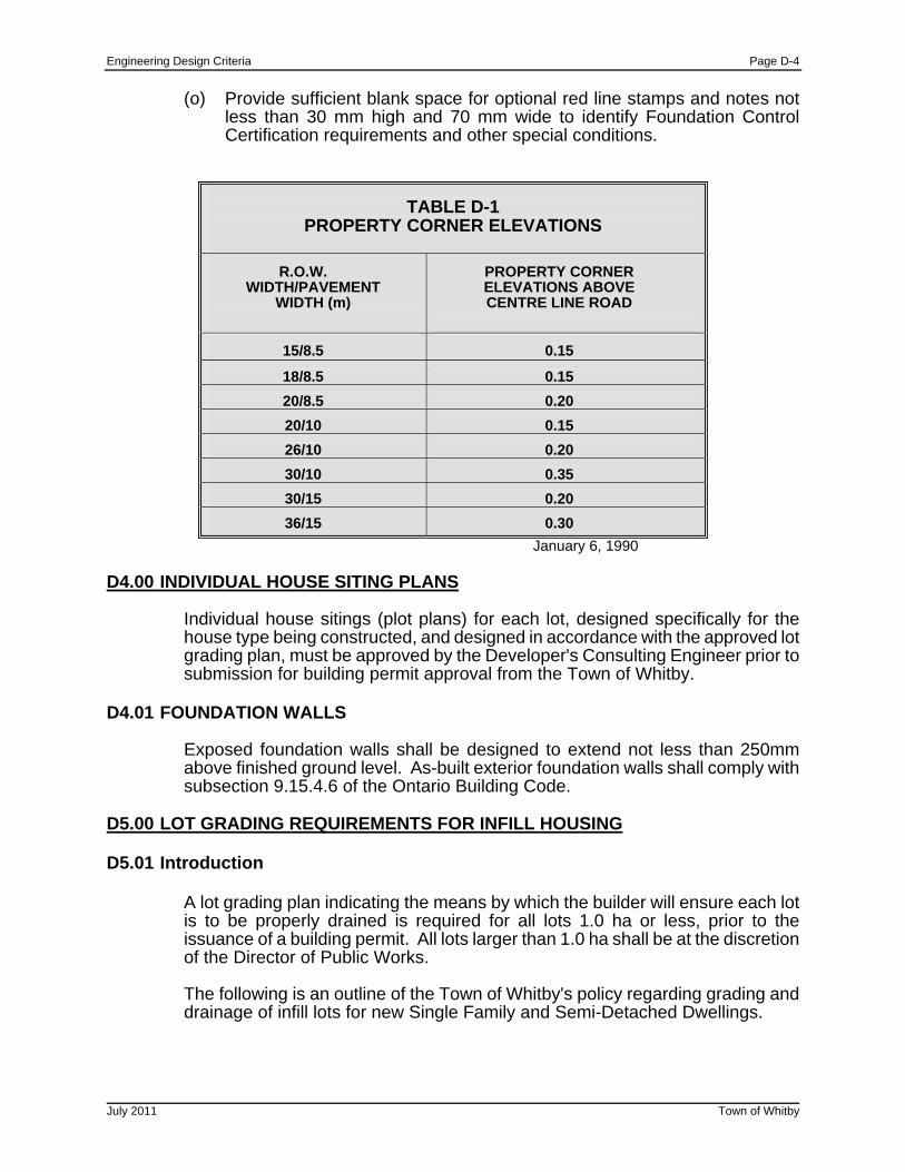
Engineering Design Criteria Page D-4
July 2011 Town of Whitby
(o) Provide sufficient blank space for optional red line stamps and notes not
less than 30 mm high and 70 mm wide to identify Foundation Control Certification requirements and other special conditions.
TABLE D-1
PROPERTY CORNER ELEVATIONS
R.O.W.
WIDTH/PAVEMENT WIDTH (m)
PROPERTY CORNER ELEVATIONS ABOVE CENTRE LINE ROAD
15/8.5
0.15
18/8.5
0.15
20/8.5
0.20
20/10
0.15
26/10
0.20
30/10
0.35
30/15
0.20
36/15
0.30
January 6, 1990 D4.00 INDIVIDUAL HOUSE SITING PLANS
Individual house sitings (plot plans) for each lot, designed specifically for the house type being constructed, and designed in accordance with the approved lot grading plan, must be approved by the Developer's Consulting Engineer prior to submission for building permit approval from the Town of Whitby.
D4.01 FOUNDATION WALLS Exposed foundation walls shall be designed to extend not less than 250mm above finished ground level. As-built exterior foundation walls shall comply with subsection 9.15.4.6 of the Ontario Building Code.
D5.00 LOT GRADING REQUIREMENTS FOR INFILL HOUSING D5.01 Introduction
A lot grading plan indicating the means by which the builder will ensure each lot is to be properly drained is required for all lots 1.0 ha or less, prior to the issuance of a building permit. All lots larger than 1.0 ha shall be at the discretion of the Director of Public Works. The following is an outline of the Town of Whitby's policy regarding grading and drainage of infill lots for new Single Family and Semi-Detached Dwellings.
Engineering Design Criteria Page D-5
July 2011 Town of Whitby
Sentence 9.14.6.1 of the Ontario Building Code requires that a site be graded “so that water will not accumulate at or near the building and will not adversely affect adjacent properties”.
It is the owner’s responsibility to retain a Grading Consultant with experience in site grading and drainage to:
(a) Prepare and sign a site grading plan for inclusion with the building permit
application,
(b) Provide field review to ensure compliance with the site grading plan, and,
(c) Issue a final grading certificate to the Engineering Department upon completion of the final grades.
The grading consultant will ensure that no new instances of ponding will occur as a result of construction. Pre-construction problem may still exist as the ramifications of the existing grade are still felt. As such, the grading consultant is required to maintain the intent of the existing grading, not improve it as a requirement, unless noted otherwise at the discretion of the Director of Public Works.
Please be advised that 3 copies of the site plan must be included with all submissions for building permit.
A 'Grading Consultant' must be one of the following:
! A Professional Engineer registered in Ontario;
! An Architect registered in Ontario; or,
! An Ontario Land Surveyor.
Engineering Design Criteria Page D-6
July 2011 Town of Whitby
D5.02 Responsibility of the Grading Consultant
The following concerns must be addressed and included by the grading consultant, as a minimum, in preparing the grading plan:
(a) A north arrow shall be shown. All drawings received shall be to scale,
1:250 or 1:200 and drawn in ink. Freehand drawings are not acceptable.
(b) Grading must meet or exceed the minimum requirements set forth in the Lot Grading Criteria, and the Town of Whitby Standards No. 300 to 304. Indicate both existing and proposed grade elevations at all corners of the house, property lines and lot corners.
(c) Note any concerns with respect to the overall performance of the existing
drainage system in the neighbourhood.
(d) Show the location of downspouts, splash pads, area drains, discharge from sump pumps, window wells, walkouts, etc. for both the infill and houses on adjacent lots.
(e) Show the location of hard surfaces such as driveways, walkways, porches,
retaining walls, etc.
(f) Show the location and diameter of all trees on Town of Whitby property in front of, adjacent to and within 7.5 m either side of the subject lot.
(g) Provide the elevations of the crown of the road at the centre line of the lot,
proposed finished basement, first floor, garage floor, sufficient driveway elevations to establish the slope, as well as elevations of porches, decks, curbs and sidewalks and the number of steps or risers at all entrances. Invert elevations of Municipal service connections are required.
(h) Indicate all existing and proposed work in the Town of Whitby road
allowance, such as existing/proposed driveway, curbs, sidewalks, culverts, all utilities, etc., on the Site Grading Plan.
(i) Show the location and dimensions of all structures on the lot, including their
setbacks to all lot lines. The lot area and building length for irregular shaped lots must be provided.
(j) A 600 mm wide strip around the lot perimeter is required to remain
undisturbed. This requirement may be waived by the Director of Public Works where warranted; however all grades must meet existing on lot lines unless written permission of adjacent property owner is attached.
(k) Provide a field review as required and submit a Sealed Final Grading
Certificate to the Town of Whitby, Engineering Section. The form shall be as per Section D5.03, page D-7 or may be obtained in the Building Department.
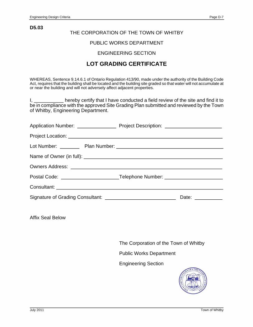
Engineering Design Criteria Page D-7
D5.03
THE CORPORATION OF THE TOWN OF WHITBY
PUBLIC WORKS DEPARTMENT
ENGINEERING SECTION
LOT GRADING CERTIFICATE
WHEREAS, Sentence 9.14.6.1 of Ontario Regulation 413/90, made under the authority of the Building Code Act, requires that the building shall be located and the building site graded so that water will not accumulate at or near the building and will not adversely affect adjacent properties.
I, hereby certify that I have conducted a field review of the site and find it to be in compliance with the approved Site Grading Plan submitted and reviewed by the Town of Whitby, Engineering Department. Application Number: Project Description: Project Location: Lot Number: Plan Number: Name of Owner (in full): Owners Address: Postal Code: Telephone Number: Consultant: Signature of Grading Consultant: Date: Affix Seal Below
The Corporation of the Town of Whitby
Public Works Department
Engineering Section
July 2011 Town of Whitby

Engineering Design Criteria Page D-8
July 2011 Town of Whitby
D5.04 Lot Grading Criteria for Infill Housing
1. The intent of the existing drainage pattern in the area of the site should be maintained.
2. Side yards should be drained at surface slopes not less than 2.0% to one or
more existing positive drainage outlets connected to public drainage systems, or if necessary to proposed positive drainage outlets.
3. Drainage swale longitudinal slopes should not be less than 2.0%.
4. Terrace and drainage swale side slopes should not exceed 33.0% (3:1)
5. Elevations at the property line fronting the street should be such that the
average slope down to the top of the roadway curb should be between 2.0% and 8.0%.
6. Rear yard slope should not exceed 5.0% except where existing grades are
not being altered.
7. Retaining walls are permitted where desired grading cannot be achieved; however, specific drawings and details must meet Town of Whitby standards or be approved by an Engineer.
8. During construction, siltation control methods should be used around the lot
perimeter in order to prevent erosion or siltation on adjacent properties.
9. In compliance with 9.14.6.1 of the Ontario Building Code the site is to be graded so that water will not accumulate at or near the building under construction and will not adversely affect any adjacent properties.
10. In compliance with subsection 9.14.6.4 of the Ontario Building Code, where
a storm sewer is not available to which downspouts may be connected, provisions shall be made to prevent soil erosion. ie: splash pads to a side yard swale.
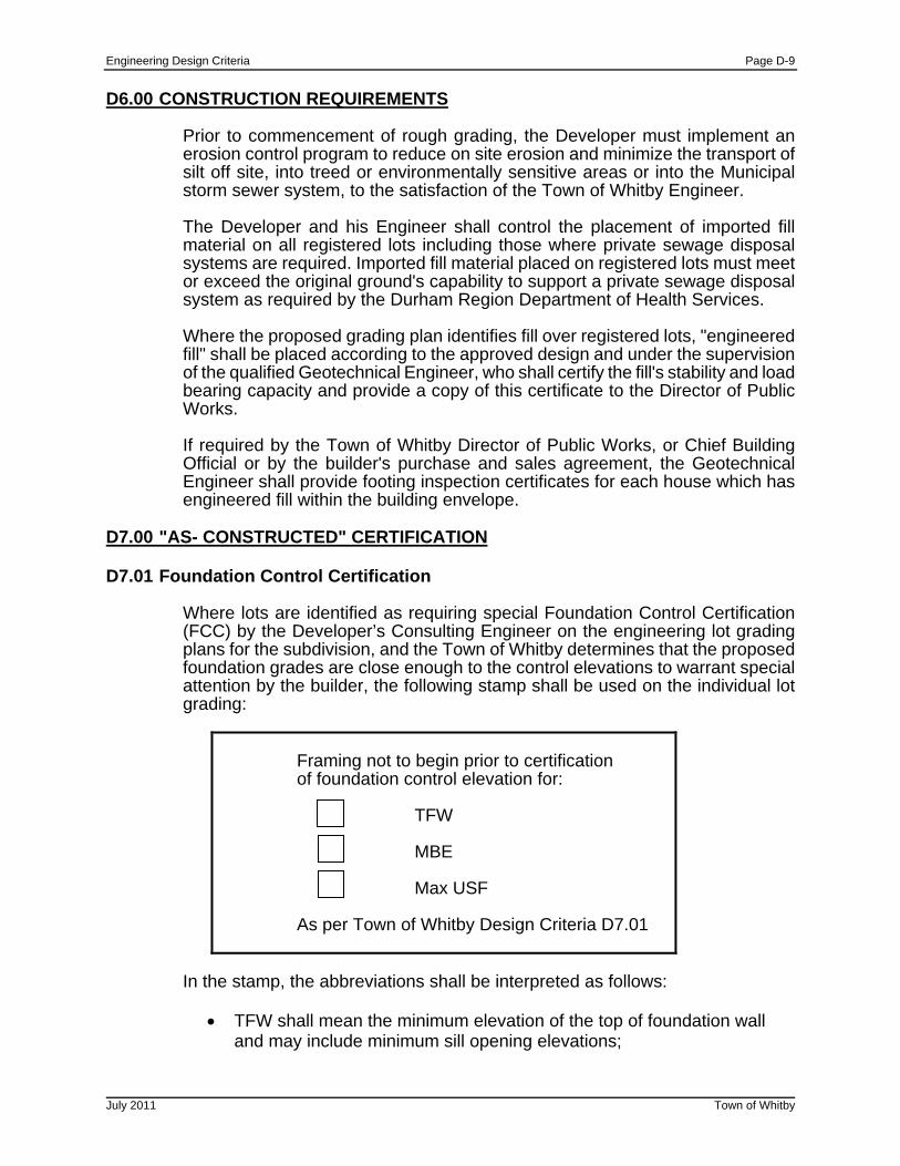
Engineering Design Criteria Page D-9
D6.00 CONSTRUCTION REQUIREMENTS
Prior to commencement of rough grading, the Developer must implement an erosion control program to reduce on site erosion and minimize the transport of silt off site, into treed or environmentally sensitive areas or into the Municipal storm sewer system, to the satisfaction of the Town of Whitby Engineer.
The Developer and his Engineer shall control the placement of imported fill material on all registered lots including those where private sewage disposal systems are required. Imported fill material placed on registered lots must meet or exceed the original ground's capability to support a private sewage disposal system as required by the Durham Region Department of Health Services.
Where the proposed grading plan identifies fill over registered lots, "engineered fill" shall be placed according to the approved design and under the supervision of the qualified Geotechnical Engineer, who shall certify the fill's stability and load bearing capacity and provide a copy of this certificate to the Director of Public Works.
If required by the Town of Whitby Director of Public Works, or Chief Building Official or by the builder's purchase and sales agreement, the Geotechnical Engineer shall provide footing inspection certificates for each house which has engineered fill within the building envelope.
D7.00 "AS- CONSTRUCTED" CERTIFICATION D7.01 Foundation Control Certification
Where lots are identified as requiring special Foundation Control Certification (FCC) by the Developer’s Consulting Engineer on the engineering lot grading plans for the subdivision, and the Town of Whitby determines that the proposed foundation grades are close enough to the control elevations to warrant special attention by the builder, the following stamp shall be used on the individual lot grading:
Framing not to begin prior to certification of foundation control elevation for: TFW MBE Max USF As per Town of Whitby Design Criteria D7.01
In the stamp, the abbreviations shall be interpreted as follows:
TFW shall mean the minimum elevation of the top of foundation wall and may include minimum sill opening elevations;
July 2011 Town of Whitby

Engineering Design Criteria Page D-10
July 2011 Town of Whitby
MBE shall mean the minimum basement elevations and shall be
interpreted to mean the control elevation of the placement of foundation drains; and
Max USF shall mean the maximum underside of footing and shall be interpreted to indicate the depth to which footings shall be extended.
The builder shall have the FCC prepared prior to beginning the framing of the unit for lots identified with the above stamp. Where the TFW, MBE or Max USF has been identified as a critical elevation for a lot or block, either a partial building permit, a conditional building permit or a separate foundation building permit only shall be permitted to be issued and subject to the approval of the Chief Building Official, construction shall not continue until a satisfactory Foundation Control Certification (FCC) has been received. For this purpose the FCC shall indicate that the required elevations are within permitted tolerances. Foundation Control Certification shall be done only by a Professional Engineer Ontario, an Ontario Land Surveyor or recognized equivalent acceptable to the Chief Building Official. The format of the Foundation Control Certificate shall be as shown in Section D7.01.
Prior to proceeding with framing of structures over registered lots, builders must provide the Town of Whitby Works Department and Developers Consulting Engineer with a Foundation Control Certification as per Town of Whitby Design Criteria Section D7.01, identifying "As-Built" underside of footing, top of foundation elevations (all locations), garage door sill elevations and actual setback distances as specified under the appropriate Zoning By-law. If a variance exists between these "As-Built" elevations and the approved house siting plan, the Consulting Engineer shall provide details of the variance from the approved plans and shall include his recommendations for rectification of the problem, if required. The special FCC shall be provided prior to framing, all other as-built elevations shall be provided as part of the final lot grading certification.
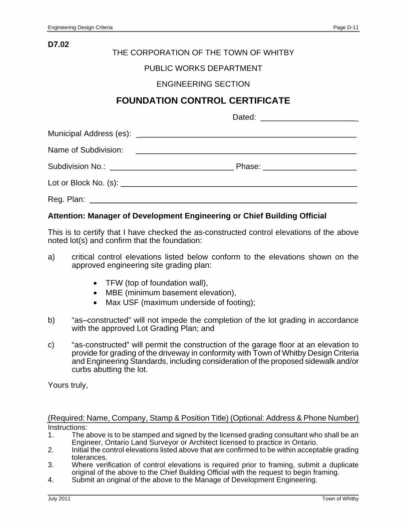
Engineering Design Criteria Page D-11
July 2011 Town of Whitby
D7.02
THE CORPORATION OF THE TOWN OF WHITBY
PUBLIC WORKS DEPARTMENT
ENGINEERING SECTION
FOUNDATION CONTROL CERTIFICATE
Dated: _ Municipal Address (es): _ Name of Subdivision: Subdivision No.: Phase: Lot or Block No. (s): Reg. Plan: Attention: Manager of Development Engineering or Chief Building Official This is to certify that I have checked the as-constructed control elevations of the above noted lot(s) and confirm that the foundation: a) critical control elevations listed below conform to the elevations shown on the approved engineering site grading plan:
TFW (top of foundation wall), MBE (minimum basement elevation), Max USF (maximum underside of footing);
b) “as–constructed” will not impede the completion of the lot grading in accordance with the approved Lot Grading Plan; and c) “as-constructed” will permit the construction of the garage floor at an elevation to provide for grading of the driveway in conformity with Town of Whitby Design Criteria and Engineering Standards, including consideration of the proposed sidewalk and/or curbs abutting the lot. Yours truly, (Required: Name, Company, Stamp & Position Title) (Optional: Address & Phone Number) Instructions: 1. The above is to be stamped and signed by the licensed grading consultant who shall be an Engineer, Ontario Land Surveyor or Architect licensed to practice in Ontario. 2. Initial the control elevations listed above that are confirmed to be within acceptable grading tolerances. 3. Where verification of control elevations is required prior to framing, submit a duplicate original of the above to the Chief Building Official with the request to begin framing. 4. Submit an original of the above to the Manage of Development Engineering.
Engineering Design Criteria Page D-12
July 2011 Town of Whitby
D7.03 As-Built Certification
Prior to the release of any lot from the conditions of the Subdivision Agreement, the Developer’s Consulting Engineer shall provide written certification to the Town of Whitby that the grading and drainage of the lot is in accordance with the approved lot grading and drainage plans. If a variance exists between these “As-Constructed” elevations and the approved house siting plan, the Consulting Engineer shall provide details of the variance from the approved plans and shall include his recommendations for rectification of the problem, if required Final lot grading certification by the Consulting Engineer shall be preceded by a pre-sodding site inspection by the Consulting Engineer and builder who will jointly determine which lots are certifiable and ready for sodding based on visual inspection, which lots the Consulting Engineer must survey to confirm the grading functions and is in accordance with the approved design, and which lots require deficiency repairs and the nature of those repairs. In all instances, "As-Constructed" geodetic elevations must be recorded on approved siting plan after sodding (typically 15 ground elevation shots per lot) and forwarded to the Town of Whitby, with the lot grading certificate. (See Section D5.03 for Certificate) which shall note any variation from original design elevations. The Town of Whitby will then review the certified lots and arrange for the release of the security deposit(s), if acceptable.

Engineering Design Criteria Page E-1
July 2011 Town of Whitby
SECTION E - STRUCTURES E1.00 GENERAL
All structures shall be fully designed and detailed on engineering drawings and shall be protected against possible erosion during and after construction. Where applicable, structures shall conform to Ontario Provincial Standard Drawings. All other structures not noted below may require certification by a qualified Engineer at the sole discretion of the Director of Public Works.
For channel, culverts, bridges and/or erosion control projects the proponent is responsible for obtaining all necessary approvals from the appropriate approval agencies such as the Conservation Authority, Ministry of Natural Resources, the Ministry of Environment and Energy and Ministry of Transportation of Ontario.
E2.00 RETAINING WALLS
All retaining walls are to be constructed of durable materials such as stone, cast in place or precast concrete. Retaining walls are to be constructed entirely within the property limits such that the benefitting property can maintain the wall without encroaching on adjacent properties. Retaining walls attached to or part of a building are subject to the requirements of the Ontario Building code and are thus excluded from the review under this standard. i) Where the retaining wall is less than 0.6 m in height, shop drawings or precast concrete manufacturer’s standard details shall be provided at the time of siting approval prior to issuance of a building permit. Certification is not required for walls less than 0.6m in height. ii) Where the retaining wall exceeds 0.6m in height, an engineering design or pre-engineered design shall be stamped by an Engineer experienced in the design and construction of retaining walls. The required engineering design shall be submitted to the Town of Whitby Engineering Department, Development Section for approval at the time of siting approval prior to the issuance of a building permit. During construction, the retaining wall shall be inspected and upon completion certified by an Engineer experienced in the design and construction of retaining walls. A fence or safety railing will be required for all retaining wall in excess of 0.6 m in height. Regardless of height, the top of any retaining wall shall not be less than 1.0 m from the toe of adjacent higher retaining wall and the maximum horizontal slope between the walls shall not be more than 5.0%.
Engineering Design Criteria Page E-2
July 2011 Town of Whitby
E3.00 CULVERTS AND BRIDGES
Driveway culverts shall be specified as Helical CSPA, 450 mm x 340 mm, 68 mm x 13 mm corrugation, 1.6 mm wall thickness. Culverts must be sized to accommodate 5 year return period storm flows unless direction for another sizing has been given by the Director of Public Works. Rural driveway culverts shall have a minimum length of 6.0 m.
Generally, driveway culverts on existing roads must be installed by or in accordance with criteria and approvals established by the road authority that has jurisdiction over the road allowance (MTO, Region of Durham or Town of Whitby).
Detailed design drawings shall be required for all reinforced concrete structures
that are poured in place. This includes all head walls, outfalls, maintenance holes and culverts where OPSS and OPSD do not specifically detail the structure. Bridges and other major drainage structures shall require special designs as determined by the Public Works Department in consultation with MTO, CLOCA and MNR. Hydraulic calculations will be required to show the hydraulic capacity of the proposed channel and what level of service or flood frequency the roadway is protected for. Generally, unless directed by a sub-watershed plan or other approved document, Arterial and Collector roads shall be protected up to the 100 year design storm. Urban local roads shall be protected up to the 50 year design storm and rural local roads shall be protected up to the 25 year storm. Temporary detour culverts should be sized to convey the 10 year storm.
E4.00 NOISE FENCES AND WALLS
All noise fences and walls are to be constructed as shown on the design drawings per Town of Whitby Standards or otherwise approved. The noise fences/wall shall be certified by a qualified Engineer prior to assumption of the subdivision. The certification shall include the section of fence being certified, materials used, construction method, structural integrity, and certification that the required noise abatement levels for the noise fences and/or walls have been met.
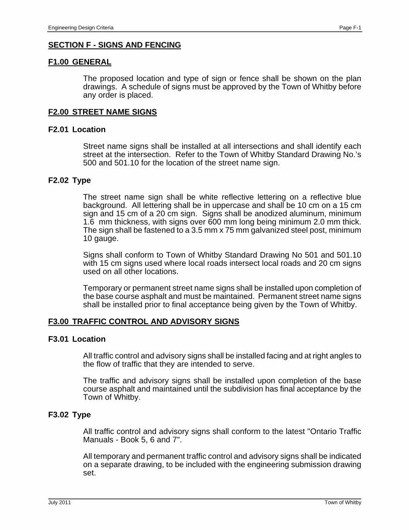
Engineering Design Criteria Page F-1
July 2011 Town of Whitby
SECTION F - SIGNS AND FENCING F1.00 GENERAL
The proposed location and type of sign or fence shall be shown on the plan drawings. A schedule of signs must be approved by the Town of Whitby before any order is placed.
F2.00 STREET NAME SIGNS F2.01 Location
Street name signs shall be installed at all intersections and shall identify each street at the intersection. Refer to the Town of Whitby Standard Drawing No.’s 500 and 501.10 for the location of the street name sign.
F2.02 Type
The street name sign shall be white reflective lettering on a reflective blue background. All lettering shall be in uppercase and shall be 10 cm on a 15 cm sign and 15 cm of a 20 cm sign. Signs shall be anodized aluminum, minimum 1.6 mm thickness, with signs over 600 mm long being minimum 2.0 mm thick. The sign shall be fastened to a 3.5 mm x 75 mm galvanized steel post, minimum 10 gauge.
Signs shall conform to Town of Whitby Standard Drawing No 501 and 501.10 with 15 cm signs used where local roads intersect local roads and 20 cm signs used on all other locations.
Temporary or permanent street name signs shall be installed upon completion of the base course asphalt and must be maintained. Permanent street name signs shall be installed prior to final acceptance being given by the Town of Whitby.
F3.00 TRAFFIC CONTROL AND ADVISORY SIGNS F3.01 Location
All traffic control and advisory signs shall be installed facing and at right angles to the flow of traffic that they are intended to serve.
The traffic and advisory signs shall be installed upon completion of the base course asphalt and maintained until the subdivision has final acceptance by the Town of Whitby.
F3.02 Type
All traffic control and advisory signs shall conform to the latest "Ontario Traffic Manuals - Book 5, 6 and 7". All temporary and permanent traffic control and advisory signs shall be indicated on a separate drawing, to be included with the engineering submission drawing set.
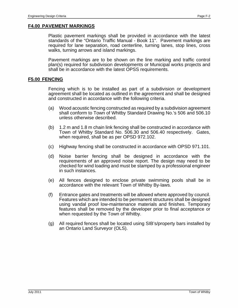
Engineering Design Criteria Page F-2
July 2011 Town of Whitby
F4.00 PAVEMENT MARKINGS
Plastic pavement markings shall be provided in accordance with the latest standards of the “Ontario Traffic Manual - Book 11". Pavement markings are required for lane separation, road centerline, turning lanes, stop lines, cross walks, turning arrows and island markings.
Pavement markings are to be shown on the line marking and traffic control plan(s) required for subdivision developments or Municipal works projects and shall be in accordance with the latest OPSS requirements.
F5.00 FENCING
Fencing which is to be installed as part of a subdivision or development agreement shall be located as outlined in the agreement and shall be designed and constructed in accordance with the following criteria.
(a) Wood acoustic fencing constructed as required by a subdivision agreement
shall conform to Town of Whitby Standard Drawing No.’s 506 and 506.10 unless otherwise described.
(b) 1.2 m and 1.8 m chain link fencing shall be constructed in accordance with
Town of Whitby Standard No. 506.30 and 506.40 respectively. Gates, when required, shall be as per OPSD 972.102.
(c) Highway fencing shall be constructed in accordance with OPSD 971.101.
(d) Noise barrier fencing shall be designed in accordance with the
requirements of an approved noise report. The design may need to be checked for wind loading and must be stamped by a professional engineer in such instances.
(e) All fences designed to enclose private swimming pools shall be in
accordance with the relevant Town of Whitby By-laws.
(f) Entrance gates and treatments will be allowed where approved by council. Features which are intended to be permanent structures shall be designed using vandal proof low-maintenance materials and finishes. Temporary features shall be removed by the developer prior to final acceptance or when requested by the Town of Whitby.
(g) All required fences shall be located using SIB’s/property bars installed by
an Ontario Land Surveyor (OLS).
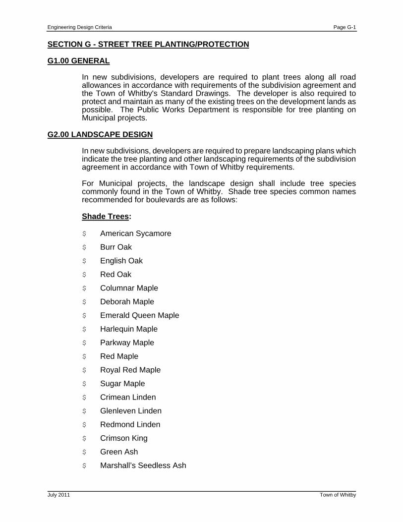
Engineering Design Criteria Page G-1
July 2011 Town of Whitby
SECTION G - STREET TREE PLANTING/PROTECTION G1.00 GENERAL
In new subdivisions, developers are required to plant trees along all road allowances in accordance with requirements of the subdivision agreement and the Town of Whitby's Standard Drawings. The developer is also required to protect and maintain as many of the existing trees on the development lands as possible. The Public Works Department is responsible for tree planting on Municipal projects.
G2.00 LANDSCAPE DESIGN
In new subdivisions, developers are required to prepare landscaping plans which indicate the tree planting and other landscaping requirements of the subdivision agreement in accordance with Town of Whitby requirements.
For Municipal projects, the landscape design shall include tree species commonly found in the Town of Whitby. Shade tree species common names recommended for boulevards are as follows: Shade Trees: $ American Sycamore
$ Burr Oak
$ English Oak
$ Red Oak
$ Columnar Maple
$ Deborah Maple
$ Emerald Queen Maple
$ Harlequin Maple
$ Parkway Maple
$ Red Maple
$ Royal Red Maple
$ Sugar Maple
$ Crimean Linden
$ Glenleven Linden
$ Redmond Linden
$ Crimson King
$ Green Ash
$ Marshall’s Seedless Ash
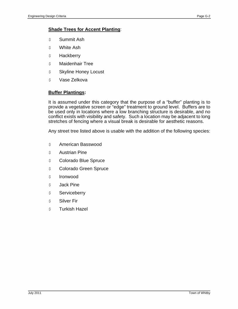
Engineering Design Criteria Page G-2
July 2011 Town of Whitby
Shade Trees for Accent Planting:
$ Summit Ash
$ White Ash
$ Hackberry
$ Maidenhair Tree
$ Skyline Honey Locust
$ Vase Zelkova
Buffer Plantings:
It is assumed under this category that the purpose of a “buffer” planting is to provide a vegetative screen or “edge” treatment to ground level. Buffers are to be used only in locations where a low branching structure is desirable, and no conflict exists with visibility and safety. Such a location may be adjacent to long stretches of fencing where a visual break is desirable for aesthetic reasons. Any street tree listed above is usable with the addition of the following species:
$ American Basswood
$ Austrian Pine
$ Colorado Blue Spruce
$ Colorado Green Spruce
$ Ironwood
$ Jack Pine
$ Serviceberry
$ Silver Fir
$ Turkish Hazel
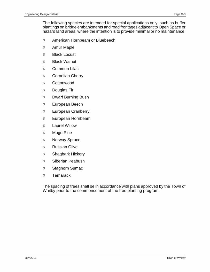
Engineering Design Criteria Page G-3
July 2011 Town of Whitby
The following species are intended for special applications only, such as buffer plantings on bridge embankments and road frontages adjacent to Open Space or hazard land areas, where the intention is to provide minimal or no maintenance.
$ American Hornbeam or Bluebeech
$ Amur Maple
$ Black Locust
$ Black Walnut
$ Common Lilac
$ Cornelian Cherry
$ Cottonwood
$ Douglas Fir
$ Dwarf Burning Bush
$ European Beech
$ European Cranberry
$ European Hornbeam
$ Laurel Willow
$ Mugo Pine
$ Norway Spruce
$ Russian Olive
$ Shagbark Hickory
$ Siberian Peabush
$ Staghorn Sumac
$ Tamarack
The spacing of trees shall be in accordance with plans approved by the Town of Whitby prior to the commencement of the tree planting program.
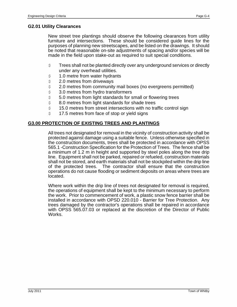
Engineering Design Criteria Page G-4
July 2011 Town of Whitby
G2.01 Utility Clearances
New street tree plantings should observe the following clearances from utility furniture and intersections. These should be considered guide lines for the purposes of planning new streetscapes, and be listed on the drawings. It should be noted that reasonable on-site adjustments of spacing and/or species will be made in the field upon stake-out as required to suit special conditions. $ Trees shall not be planted directly over any underground services or directly
under any overhead utilities. $ 1.0 metre from water hydrants $ 2.0 metres from driveways $ 2.0 metres from community mail boxes (no evergreens permitted) $ 3.0 metres from hydro transformers $ 5.0 metres from light standards for small or flowering trees $ 8.0 metres from light standards for shade trees $ 15.0 metres from street intersections with no traffic control sign $ 17.5 metres from face of stop or yield signs
G3.00 PROTECTION OF EXISTING TREES AND PLANTINGS
All trees not designated for removal in the vicinity of construction activity shall be protected against damage using a suitable fence. Unless otherwise specified in the construction documents, trees shall be protected in accordance with OPSS 565.1 -Construction Specification for the Protection of Trees. The fence shall be a minimum of 1.2 m in height and supported by steel poles along the tree drip line. Equipment shall not be parked, repaired or refueled, construction materials shall not be stored, and earth materials shall not be stockpiled within the drip line of the protected trees. The contractor shall ensure that the construction operations do not cause flooding or sediment deposits on areas where trees are located.
Where work within the drip line of trees not designated for removal is required, the operations of equipment shall be kept to the minimum necessary to perform the work. Prior to commencement of work, a plastic snow fence barrier shall be installed in accordance with OPSD 220.010 - Barrier for Tree Protection. Any trees damaged by the contractor's operations shall be repaired in accordance with OPSS 565.07.03 or replaced at the discretion of the Director of Public Works.
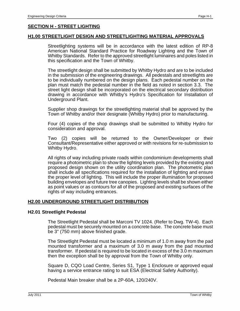
Engineering Design Criteria Page H-1
July 2011 Town of Whitby
SECTION H - STREET LIGHTING H1.00 STREETLIGHT DESIGN AND STREETLIGHTING MATERIAL APPROVALS
Streetlighting systems will be in accordance with the latest edition of RP-8 American National Standard Practice for Roadway Lighting and the Town of Whitby Standards. Refer to the approved streetlight luminaires and poles listed in this specification and the Town of Whitby. The streetlight design shall be submitted by Whitby Hydro and are to be included in the submission of the engineering drawings. All pedestals and streetlights are to be individually numbered on the design plans. Each pedestal number on the plan must match the pedestal number in the field as noted in section 3.3. The street light design shall be incorporated on the electrical secondary distribution drawing in accordance with Whitby’s Hydro’s Specification for Installation of Underground Plant.
Supplier shop drawings for the streetlighting material shall be approved by the Town of Whitby and/or their designate (Whitby Hydro) prior to manufacturing.
Four (4) copies of the shop drawings shall be submitted to Whitby Hydro for consideration and approval.
Two (2) copies will be returned to the Owner/Developer or their Consultant/Representative either approved or with revisions for re-submission to Whitby Hydro. All rights of way including private roads within condominium developments shall require a photometric plan to show the lighting levels provided by the existing and proposed design shown on the utility coordination plan. The photometric plan shall include all specifications required for the installation of lighting and ensure the proper level of lighting. This will include the proper illumination for proposed building envelopes and future tree canopies. Lighting levels shall be shown either as point values or as contours for all of the proposed and existing surfaces of the rights of way including entrances.
H2.00 UNDERGROUND STREETLIGHT DISTRIBUTION H2.01 Streetlight Pedestal
The Streetlight Pedestal shall be Marconi TV 1024. (Refer to Dwg. TW-4). Each pedestal must be securely mounted on a concrete base. The concrete base must be 3" (750 mm) above finished grade.
The Streetlight Pedestal must be located a minimum of 1.0 m away from the pad mounted transformer and a maximum of 3.0 m away from the pad mounted transformer. If pedestal is required to be located in excess of the 3.0 m maximum then the exception shall be by approval from the Town of Whitby only.
Square D, CQO Load Centre, Series S1, Type 1 Enclosure or approved equal having a service entrance rating to suit ESA (Electrical Safety Authority).
Pedestal Main breaker shall be a 2P-60A, 120/240V.
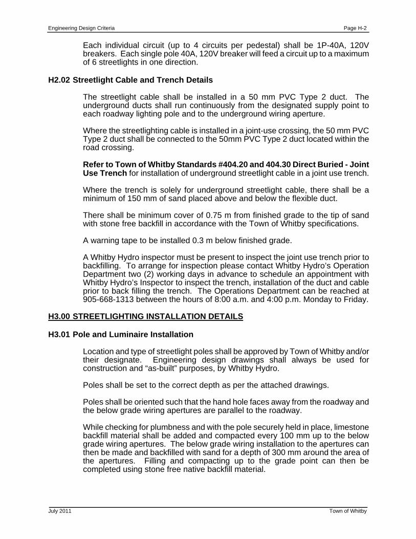
Engineering Design Criteria Page H-2
July 2011 Town of Whitby
Each individual circuit (up to 4 circuits per pedestal) shall be 1P-40A, 120V breakers. Each single pole 40A, 120V breaker will feed a circuit up to a maximum of 6 streetlights in one direction.
H2.02 Streetlight Cable and Trench Details
The streetlight cable shall be installed in a 50 mm PVC Type 2 duct. The underground ducts shall run continuously from the designated supply point to each roadway lighting pole and to the underground wiring aperture.
Where the streetlighting cable is installed in a joint-use crossing, the 50 mm PVC Type 2 duct shall be connected to the 50mm PVC Type 2 duct located within the road crossing.
Refer to Town of Whitby Standards #404.20 and 404.30 Direct Buried - Joint Use Trench for installation of underground streetlight cable in a joint use trench.
Where the trench is solely for underground streetlight cable, there shall be a minimum of 150 mm of sand placed above and below the flexible duct.
There shall be minimum cover of 0.75 m from finished grade to the tip of sand with stone free backfill in accordance with the Town of Whitby specifications.
A warning tape to be installed 0.3 m below finished grade.
A Whitby Hydro inspector must be present to inspect the joint use trench prior to backfilling. To arrange for inspection please contact Whitby Hydro’s Operation Department two (2) working days in advance to schedule an appointment with Whitby Hydro’s Inspector to inspect the trench, installation of the duct and cable prior to back filling the trench. The Operations Department can be reached at 905-668-1313 between the hours of 8:00 a.m. and 4:00 p.m. Monday to Friday.
H3.00 STREETLIGHTING INSTALLATION DETAILS H3.01 Pole and Luminaire Installation
Location and type of streetlight poles shall be approved by Town of Whitby and/or their designate. Engineering design drawings shall always be used for construction and “as-built” purposes, by Whitby Hydro.
Poles shall be set to the correct depth as per the attached drawings.
Poles shall be oriented such that the hand hole faces away from the roadway and the below grade wiring apertures are parallel to the roadway.
While checking for plumbness and with the pole securely held in place, limestone backfill material shall be added and compacted every 100 mm up to the below grade wiring apertures. The below grade wiring installation to the apertures can then be made and backfilled with sand for a depth of 300 mm around the area of the apertures. Filling and compacting up to the grade point can then be completed using stone free native backfill material.
Engineering Design Criteria Page H-3
July 2011 Town of Whitby
H3.02 Streetlighting Pedestal Installation
All wiring must conform to the latest edition of the Ontario Electrical Safety Code and is subject to ESA (Electrical Safety Authority) Inspection. Each streetlight pedestal shall be energized at 120/240 volts. Up to four (4) individual single pole, 40 amps, 120 volt circuits per pedestal location.
All streetlight pedestals are to be numbered to match the numbers on the streetlight plans by the electrical contractor. The circuit breakers shall be identified in each pedestal. The Whitby Hydro Intergraph pole number identification for each streetlight pole and its corresponding circuit breaker shall be identified in each pedestal. On the inside of each hand hole plate of each streetlight pole the supply pedestal number and corresponding circuit breaker for that pole shall be listed.
Please refer to the Town of Whitby Standard Drawings 504.10, 504.20 and 504.30 in conjunction with these specifications.
H4.00 STREETLIGHT CONNECTIONS
Electrical contractor will supply and complete all electrical connections within the streetlight pedestal. Whitby Hydro will complete the final connections in the streetlight pole and energize the streetlights.
H5.00 INSPECTION, APPROVAL AND ACTIVATION
It is the responsibility of the Electrical Contractor to make arrangements with ESA (Electrical Safety Authority) for permits and inspections of both the above ground works and the below ground works. Copies of the permits and the ESA inspection reports must be forwarded to Whitby Hydro.
Whitby Hydro shall inspect the initial installation of the streetlight; lamp and photocell must be dated. The streetlight pole must be straight and hand hole cover plates installed complete with tamperproof screws. Any deficiencies shall be recorded and the contractor will be notified in writing.
H6.00 WARRANTY PERIOD AND FINAL INSPECTION
The owner/developer will be responsible to maintain the street lighting for a minimum period of two (2) years from the date of energization of the streetlights. Prior to the expiry of the warranty period the Town of Whitby and/or its representative will perform a final inspection of the streetlights and notify the consultant and/or Developer in writing of any deficiencies. All deficiencies must be corrected prior to the Town of Whitby accepting the streetlight plant.
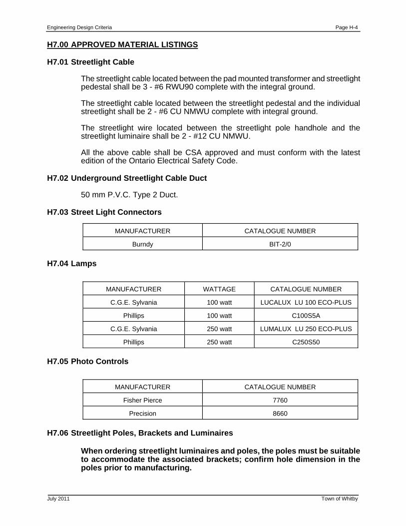
Engineering Design Criteria Page H-4
July 2011 Town of Whitby
H7.00 APPROVED MATERIAL LISTINGS H7.01 Streetlight Cable
The streetlight cable located between the pad mounted transformer and streetlight pedestal shall be 3 - #6 RWU90 complete with the integral ground.
The streetlight cable located between the streetlight pedestal and the individual streetlight shall be 2 - #6 CU NMWU complete with integral ground.
The streetlight wire located between the streetlight pole handhole and the streetlight luminaire shall be 2 - #12 CU NMWU.
All the above cable shall be CSA approved and must conform with the latest edition of the Ontario Electrical Safety Code.
H7.02 Underground Streetlight Cable Duct
50 mm P.V.C. Type 2 Duct. H7.03 Street Light Connectors
MANUFACTURER
CATALOGUE NUMBER
Burndy
BIT-2/0
H7.04 Lamps
MANUFACTURER
WATTAGE
CATALOGUE NUMBER
C.G.E. Sylvania
100 watt
LUCALUX LU 100 ECO-PLUS
Phillips
100 watt
C100S5A
C.G.E. Sylvania
250 watt
LUMALUX LU 250 ECO-PLUS
Phillips
250 watt
C250S50
H7.05 Photo Controls
MANUFACTURER
CATALOGUE NUMBER
Fisher Pierce
7760
Precision
8660
H7.06 Streetlight Poles, Brackets and Luminaires
When ordering streetlight luminaires and poles, the poles must be suitable to accommodate the associated brackets; confirm hole dimension in the poles prior to manufacturing.
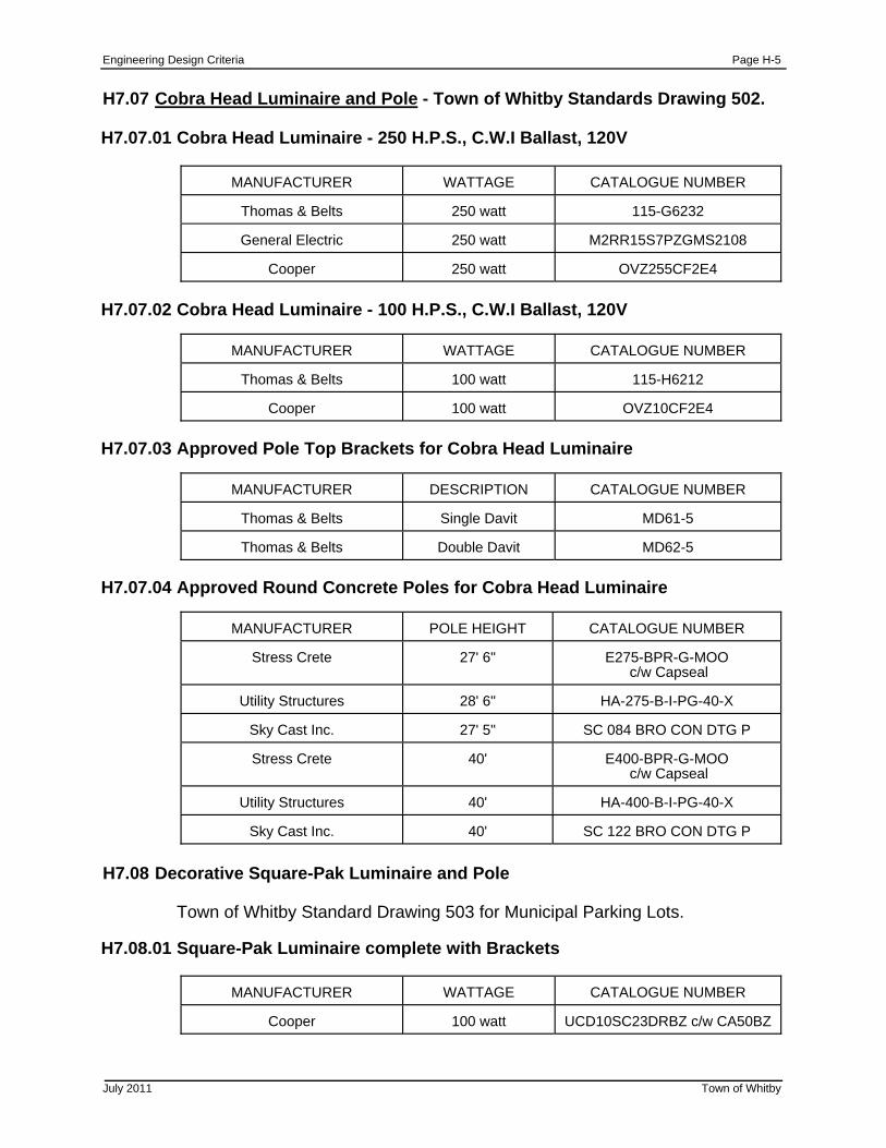
Engineering Design Criteria Page H-5
July 2011 Town of Whitby
H7.07 Cobra Head Luminaire and Pole - Town of Whitby Standards Drawing 502. H7.07.01 Cobra Head Luminaire - 250 H.P.S., C.W.I Ballast, 120V
MANUFACTURER
WATTAGE
CATALOGUE NUMBER
Thomas & Belts
250 watt
115-G6232
General Electric
250 watt
M2RR15S7PZGMS2108
Cooper
250 watt
OVZ255CF2E4
H7.07.02 Cobra Head Luminaire - 100 H.P.S., C.W.I Ballast, 120V
MANUFACTURER
WATTAGE
CATALOGUE NUMBER
Thomas & Belts
100 watt
115-H6212
Cooper
100 watt
OVZ10CF2E4
H7.07.03 Approved Pole Top Brackets for Cobra Head Luminaire
MANUFACTURER
DESCRIPTION
CATALOGUE NUMBER
Thomas & Belts
Single Davit
MD61-5
Thomas & Belts
Double Davit
MD62-5
H7.07.04 Approved Round Concrete Poles for Cobra Head Luminaire
MANUFACTURER
POLE HEIGHT
CATALOGUE NUMBER
Stress Crete
27' 6"
E275-BPR-G-MOO
c/w Capseal
Utility Structures
28' 6"
HA-275-B-I-PG-40-X
Sky Cast Inc.
27' 5"
SC 084 BRO CON DTG P
Stress Crete
40'
E400-BPR-G-MOO c/w Capseal
Utility Structures
40'
HA-400-B-I-PG-40-X
Sky Cast Inc.
40'
SC 122 BRO CON DTG P
H7.08 Decorative Square-Pak Luminaire and Pole Town of Whitby Standard Drawing 503 for Municipal Parking Lots. H7.08.01 Square-Pak Luminaire complete with Brackets
MANUFACTURER
WATTAGE
CATALOGUE NUMBER
Cooper
100 watt
UCD10SC23DRBZ c/w CA50BZ
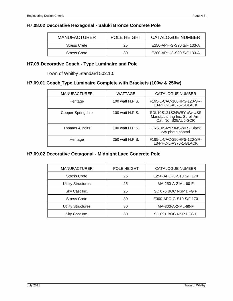
Engineering Design Criteria Page H-6
July 2011 Town of Whitby
H7.08.02 Decorative Hexagonal - Saluki Bronze Concrete Pole
MANUFACTURER
POLE HEIGHT
CATALOGUE NUMBER
Stress Crete
25'
E250-APH-G-S90 S/F 133-A
Stress Crete
30'
E300-APH-G-S90 S/F 133-A
H7.09 Decorative Coach - Type Luminaire and Pole Town of Whitby Standard 502.10. H7.09.01 Coach Type Luminaire Complete with Brackets (100w & 250w)
MANUFACTURER
WATTAGE
CATALOGUE NUMBER
Heritage
100 watt H.P.S.
F195-L-CAC-100HPS-120-SR-
L3-PHC-L-A376-1-BLACK
Cooper-Springdale
100 watt H.P.S. SDL10S121S24WBY c/w USS Manufacturing Inc. Scroll Arm
Cat. No. S25AU5-SCR
Thomas & Belts
100 watt H.P.S.
GRS10S4YP3MSWIR - Black c/w photo control
Heritage
250 watt H.P.S.
F195-L-CAC-250HPS-120-SR-
L3-PHC-L-A376-1-BLACK
H7.09.02 Decorative Octagonal - Midnight Lace Concrete Pole
MANUFACTURER
POLE HEIGHT
CATALOGUE NUMBER
Stress Crete
25'
E250-APO-G-S10 S/F 170
Utility Structures
25'
MA-250-A-2-ML-60-F
Sky Cast Inc.
25'
SC 076 BOC NSP DFG P
Stress Crete
30'
E300-APO-G-S10 S/F 170
Utility Structures
30'
MA-300-A-2-ML-60-F
Sky Cast Inc.
30'
SC 091 BOC NSP DFG P
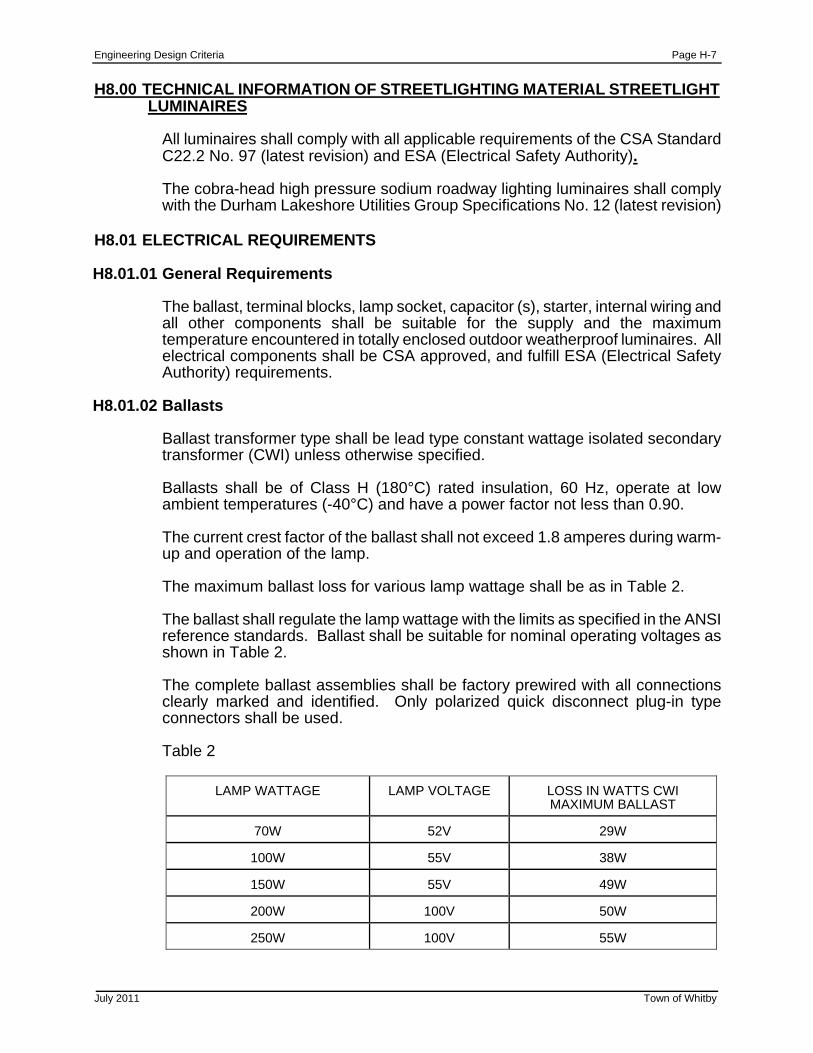
Engineering Design Criteria Page H-7
July 2011 Town of Whitby
H8.00 TECHNICAL INFORMATION OF STREETLIGHTING MATERIAL STREETLIGHT LUMINAIRES
All luminaires shall comply with all applicable requirements of the CSA Standard C22.2 No. 97 (latest revision) and ESA (Electrical Safety Authority).
The cobra-head high pressure sodium roadway lighting luminaires shall comply with the Durham Lakeshore Utilities Group Specifications No. 12 (latest revision)
H8.01 ELECTRICAL REQUIREMENTS H8.01.01 General Requirements
The ballast, terminal blocks, lamp socket, capacitor (s), starter, internal wiring and all other components shall be suitable for the supply and the maximum temperature encountered in totally enclosed outdoor weatherproof luminaires. All electrical components shall be CSA approved, and fulfill ESA (Electrical Safety Authority) requirements.
H8.01.02 Ballasts
Ballast transformer type shall be lead type constant wattage isolated secondary transformer (CWI) unless otherwise specified.
Ballasts shall be of Class H (180°C) rated insulation, 60 Hz, operate at low ambient temperatures (-40°C) and have a power factor not less than 0.90.
The current crest factor of the ballast shall not exceed 1.8 amperes during warm-up and operation of the lamp.
The maximum ballast loss for various lamp wattage shall be as in Table 2. The ballast shall regulate the lamp wattage with the limits as specified in the ANSI reference standards. Ballast shall be suitable for nominal operating voltages as shown in Table 2.
The complete ballast assemblies shall be factory prewired with all connections clearly marked and identified. Only polarized quick disconnect plug-in type connectors shall be used.
Table 2
LAMP WATTAGE
LAMP VOLTAGE
LOSS IN WATTS CWI MAXIMUM BALLAST
70W
52V
29W
100W
55V
38W
150W
55V
49W
200W
100V
50W
250W
100V
55W
Engineering Design Criteria Page H-8
July 2011 Town of Whitby
H8.01.03 Capacitors
The capacitors shall be non PCB. The terminals shall be polarized, quick disconnect, plug-in type. All capacitors shall be supplied with a removable cover made of insulating type material over the terminals.
H8.01.04 Starter
The starter shall be a self-contained, sealed, moisture proof unit. The terminals shall be polarized, quick disconnect, plug-in type. The starter shall provide starting pulses within the limits specified in the individual ANSI Reference Standards for High Pressure Sodium Lamps.
H8.01.05 Terminal Block
A terminal block shall be provided for the connection of the supply wires to the ballast leads. Screws used on the terminal block shall be captive and suitable for copper and aluminum wire sizes ranging from #10 AWG to #16 AWG. The terminal block shall be placed adjacent to the wire entry location in a readily accessible location with sufficient space to accommodation ease of wire termination.
H8.02 PHYSICAL CHARACTERISTICS H8.02.01 General
The luminaire housing shall be cast aluminum with corrosion resistant hardware.
The reflector shall be fabricated of polished, chemically brightened anodized aluminum not subject to distortion and shall be securely fastened.
The optical system of the luminaire shall be designed to avoid reflecting energy to the arc tube appendage.
The luminaire shall be designed in a manner to ensure the lamp voltage of new High Pressure Sodium lamps does not increase more than specified in the individual ANSI Reference Standards for High Pressure Sodium Lamps, when going from stabilized bare-lamp operation to stabilized operation with the closed luminaire.
Gaskets shall be provided between the reflector and refractor and between the reflector and lamp socket to prevent ingress of dirt, insects, etc.
The lamp sockets shall be cold-molded porcelain and pulse rated for use with UPS lamps. The lamp sockets shall be fitted with a corrosion resistant Mogul Screw shell suitable for outdoor applications.
The luminaire assembly when closed and in the operating position shall not be subject to damage by vibration.
All component parts in the luminaire shall be secured using screws and if required, metal brackets. No tape, Velcro or glue shall be used. All screws in the luminaire shall be o one type, preferable hexagonal head.
Engineering Design Criteria Page H-9
July 2011 Town of Whitby
H8.02.02 Cobra Head Luminaires
The bottom section of the housing shall be hinged to the top section and shall allow the lower housing and refractor to hang freely in the vertical position when open to provide easy access to all component parts including the slip fitter. The bottom section shall remain secure when in the open position.
The slip fitter mounting assembly shall be totally enclosed within the luminaire and shall provide a safe clamping mechanism for a 51 mm IPS diameter pipe and vertical adjustment of ±3° minimum.
The luminaire shall be equipped with a refractor type lens unless otherwise specified.
The refractor shall be hear-resistant glass with high resistance to breakage from thermal shock and shall be securely attached to the frame of the lower housing.
The lamp socket position shall be preset at the factory to provide the specified IES light distribution patterns when using clear lamps in accordance with ANSI/IBS RP-8.
The luminaire shall be equipped with twist lock (complete with shorting cap) receptacle unless otherwise specified, in accordance with ANSI Standard Cq36, located on tip of the housing for mounting a photoelectric control.
A leveling surface shall be provided and identified on the top of each luminaire.
Each luminaire shall be supplied complete with a bird stop in place.
H8.03 MARKING H8.03.01 Luminaire
A permanently attached corrosion resistant label shall be provided on the interior of the luminaire indicating:
(a) the manufacturer’s name or trade mark (b) catalogue number (c) wattage (d) suitable supply voltage and frequency (e) input current (f) nominal operating voltage of the lamp (g) date of manufacture A permanently attached corrosion resistant label indicating the socket positions required to provide the various photo-metric distribution patterns obtainable by use of various lamps shall be provided and attached to the interior of the cobra head luminaire so that it is clearly visible during maintenance operations.
Engineering Design Criteria Page H-10
July 2011 Town of Whitby
H8.03.02 Ballast
A permanently attached corrosion resistant nameplate shall be provided on each ballast clearly indicating:
(a) the manufacturer’s name or trade mark (b) catalogue number (c) ballast type (d) wattage (e) suitable supply voltage and frequency (f) input current (g) nominal operating voltage of the lamp (h) ballast schematic wiring diagram
H8.03.03 Paint Finish
Luminaires fabricated of steel shall have a hop dip galvanized coating prior to painting.
Luminaires fabricated of steel and specified to be finished with a high grade baked enamel paint shall be prime painted with a good quality primer.
Luminaires fabricated of sheet aluminum and specified to have a paint finish shall be finished with a baked polyester powder coating.
Luminaires made of cast aluminum and specified to have a paint finish shall only be finished with a high grade backed enamel paint.
H8.04 TECHNICAL INFORMATION TO BE SUPPLIED
Nominal line voltage Ballast type Lamp Wattage PC Receptacle provision Lamp type Luminaire classification Finish Housing Type
H8.05 PHOTO ELECTRIC CONTROLLERS H8.05.01 Size and Weight
(a) outside diameter shall be no less than 75 mm (b) height above socket when mounted shall be 60 mm or less (c) net weight shall be 25 kg or less
H8.05.02 Plug
The plug shall fit the standard three terminal locking-type receptacles as per ANSI Specification C136.10. The plug blades shall be composed of solid brass.
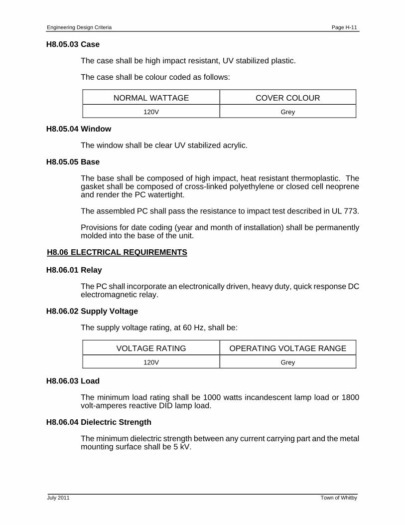
Engineering Design Criteria Page H-11
July 2011 Town of Whitby
H8.05.03 Case
The case shall be high impact resistant, UV stabilized plastic.
The case shall be colour coded as follows:
NORMAL WATTAGE
COVER COLOUR
120V
Grey
H8.05.04 Window
The window shall be clear UV stabilized acrylic. H8.05.05 Base
The base shall be composed of high impact, heat resistant thermoplastic. The gasket shall be composed of cross-linked polyethylene or closed cell neoprene and render the PC watertight.
The assembled PC shall pass the resistance to impact test described in UL 773.
Provisions for date coding (year and month of installation) shall be permanently molded into the base of the unit.
H8.06 ELECTRICAL REQUIREMENTS H8.06.01 Relay
The PC shall incorporate an electronically driven, heavy duty, quick response DC electromagnetic relay.
H8.06.02 Supply Voltage
The supply voltage rating, at 60 Hz, shall be:
VOLTAGE RATING
OPERATING VOLTAGE RANGE
120V
Grey
H8.06.03 Load
The minimum load rating shall be 1000 watts incandescent lamp load or 1800 volt-amperes reactive DID lamp load.
H8.06.04 Dielectric Strength
The minimum dielectric strength between any current carrying part and the metal mounting surface shall be 5 kV.
Engineering Design Criteria Page H-12
July 2011 Town of Whitby
H8.06.05 Surge/Lighting Protection
Surge protection shall consist of a metal oxide varister (MOV) wired line to neutral. The MOV shall have a 160J, 6500A and a 320 RMS rating. The clamping voltage shall be a maximum of 810V.
H8.06.06 Temperature Range
Each PC shall operate reliably within an ambient temperature range f -40°C to +65°C.
H8.06.07 Humidity
Each PC shall operate normally at relative humidity up through 96% at 50°C for 168 hours when subjected to rated voltage and frequency.
H8.06.08 Weatherproof Base
The weatherproof mounting, when properly attached to its mounting receptacle, shall exclude beating rain, snow, dust and insects from the receptacle.
H8.06.09 Rainproof Case
The waterproof case shall remain operative when subjected to water delivered at an angle of 45° to the vertical in the direction (s) most likely to cause water to enter.
H8.06.10 Photoelectric Sensor
The PC shall be equipped with a cadmium sulphide cell hermetically sealed to prevent damage due to moisture and chemical pollutant.
H8.06.11 Factory Set Operation
TURN-ON 1.0 fc (=/-20%) nominal TURN-OFF 1.2 fc maximum RATIO OFF/ON 2:1 nominal
H8.06.12 Failure Mode
Each PC shall have normally closed contact (i.e.: fail on). H8.06.13 Time Delay Thermal Switch
A time delay of 2 to 5 seconds for switching off shall be incorporated to prevent false operation from lightning flashes and other transitory light. There shall be no time delay feature during the day time in which turn-on will be instantaneous allowing for quick glove testing for installation and maintenance purposes.
H8.06.14 Rated Life
The rated life shall be a minimum of 5000 On-Off operations at rated load with no chattering of the relay contacts upon opening and closing.
Engineering Design Criteria Page H-13
July 2011 Town of Whitby
H8.07 MARKING
Each PC shall be clearly and permanently marked indicating:
(a) the manufacturer’s name or trademark (b) catalogue number (c) date of manufacture (d) north reference mark (e) voltage (f) load rating
Provision shall be made for date coding (year and month of installation) either on the base or on the cover of the PC.
H8.08 WARRANTY
The manufacturer shall warrant that the photoelectric controller, inclusive of all component parts furnished shall conform to all the requirements and conditions of this specification.
The manufacturer shall replace or repair, at no expense to the utility, defects due to faulty workmanship, material or design for the period of five (5) years after installation, but in no case for more than six (6) years after receipt of the unit by the utility.
All shipping charges shall be the responsibility of the supplier.
The manufacturer shall provide a further warranty for a minimum period of five (5) years on all replacement PC’s from the date of installation.
H8.09 TAPERED ELLIPTICAL ALUMINUM BRACKETS
The tapered elliptical aluminum bracket shall comply with the Durham Lakeshore Utilities Group Specification No. 14 (Latest Revision).
Engineering Design Criteria Page H-14
July 2011 Town of Whitby
H8.10 REFERENCE STANDARDS
Brackets shall comply with all applicable requirements in the latest issues of the following standards:
ANSI Standard C 136.13 Metal Bracket for wood poles used in road lighting
ASTM Standard B221 Aluminum alloy extruded bars, rods, wires,
shapes and tubes
ASTM Standard B241 Aluminum alloy seamless pipe and seamless extruded tube
CSA HA Series Aluminum and aluminum alloys
CSA Standard S244 Welded aluminum design and workmanship (inert
gas shielded arc processes)
CSA Standard S157 Strength design in aluminum
CSA Stand W59.2 Welded aluminum construction H8.11 MECHANICAL REQUIREMENT H8.11.01 Strength
The bracket arm shall be one piece seamless tubing, fabricated from aluminum alloy No. 6063-T6 one piece seamless tubing as per ASTM Standards B22 1 and B24 1.
The Alloy 6063-T6 shall have a minimum yield strength if 165 MPa (24,000 psi) and a minimum ultimate tensile strength of 193 Mpa (28,000 psi) after fabrication and any subsequent tempering.
The bracket shall not be torn apart or otherwise when subjected to an applied load of 115 kg applied vertically and 25 kg applied horizontally, each load being applied separately for ten (10) minutes duration at a point not more than 150 mm from the luminaire end of the bracket.
H8.11.02 Load Test
The bracket, while supporting a luminaire under Class C loading, shall withstand, without permanent deformation, a wind load of 3.6 kg (approx. 88 km/h or 44 mph) and an ice load of 1.27 cm or alternatively, and 18 kg wind load (approx. 130 km/h or 80 mph) without ice.
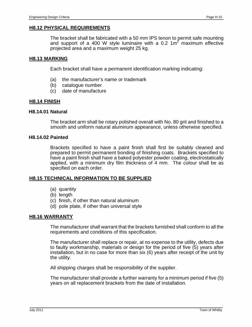
Engineering Design Criteria Page H-15
July 2011 Town of Whitby
H8.12 PHYSICAL REQUIREMENTS
The bracket shall be fabricated with a 50 mm IPS tenon to permit safe mounting and support of a 400 W style luminaire with a 0.2 1m2 maximum effective projected area and a maximum weight 25 kg.
H8.13 MARKING
Each bracket shall have a permanent identification marking indicating:
(a) the manufacturer’s name or trademark (b) catalogue number (c) date of manufacture
H8.14 FINISH H8.14.01 Natural
The bracket arm shall be rotary polished overall with No. 80 grit and finished to a smooth and uniform natural aluminum appearance, unless otherwise specified.
H8.14.02 Painted
Brackets specified to have a paint finish shall first be suitably cleaned and prepared to permit permanent bonding of finishing coats. Brackets specified to have a paint finish shall have a baked polyester powder coating, electrostatically applied, with a minimum dry film thickness of 4 mm. The colour shall be as specified on each order.
H8.15 TECHNICAL INFORMATION TO BE SUPPLIED
(a) quantity (b) length (c) finish, if other than natural aluminum (d) pole plate, if other than universal style
H8.16 WARRANTY
The manufacturer shall warrant that the brackets furnished shall conform to all the requirements and conditions of this specification.
The manufacturer shall replace or repair, at no expense to the utility, defects due to faulty workmanship, materials or design for the period of five (5) years after installation, but in no case for more than six (6) years after receipt of the unit by the utility.
All shipping charges shall be responsibility of the supplier.
The manufacturer shall provide a further warranty for a minimum period if five (5) years on all replacement brackets from the date of installation.
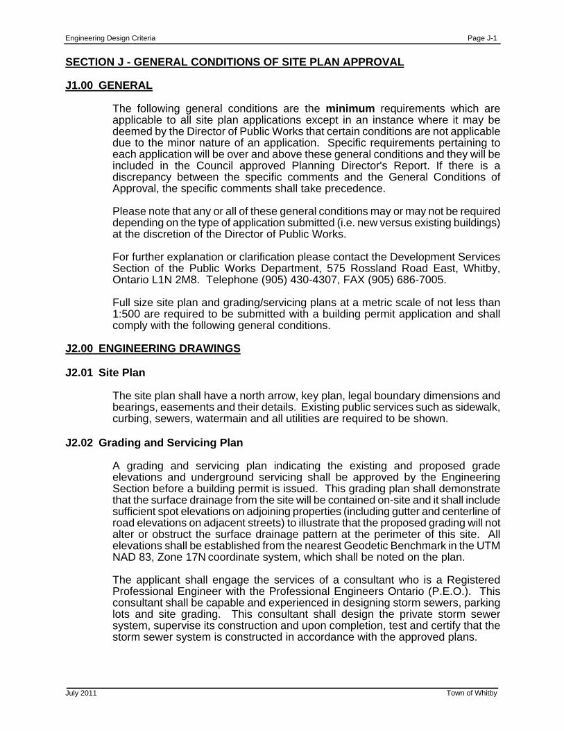
Engineering Design Criteria Page J-1
July 2011 Town of Whitby
SECTION J - GENERAL CONDITIONS OF SITE PLAN APPROVAL J1.00 GENERAL
The following general conditions are the minimum requirements which are applicable to all site plan applications except in an instance where it may be deemed by the Director of Public Works that certain conditions are not applicable due to the minor nature of an application. Specific requirements pertaining to each application will be over and above these general conditions and they will be included in the Council approved Planning Director's Report. If there is a discrepancy between the specific comments and the General Conditions of Approval, the specific comments shall take precedence.
Please note that any or all of these general conditions may or may not be required depending on the type of application submitted (i.e. new versus existing buildings) at the discretion of the Director of Public Works.
For further explanation or clarification please contact the Development Services Section of the Public Works Department, 575 Rossland Road East, Whitby, Ontario L1N 2M8. Telephone (905) 430-4307, FAX (905) 686-7005.
Full size site plan and grading/servicing plans at a metric scale of not less than 1:500 are required to be submitted with a building permit application and shall comply with the following general conditions.
J2.00 ENGINEERING DRAWINGS J2.01 Site Plan
The site plan shall have a north arrow, key plan, legal boundary dimensions and bearings, easements and their details. Existing public services such as sidewalk, curbing, sewers, watermain and all utilities are required to be shown.
J2.02 Grading and Servicing Plan
A grading and servicing plan indicating the existing and proposed grade elevations and underground servicing shall be approved by the Engineering Section before a building permit is issued. This grading plan shall demonstrate that the surface drainage from the site will be contained on-site and it shall include sufficient spot elevations on adjoining properties (including gutter and centerline of road elevations on adjacent streets) to illustrate that the proposed grading will not alter or obstruct the surface drainage pattern at the perimeter of this site. All elevations shall be established from the nearest Geodetic Benchmark in the UTM NAD 83, Zone 17N coordinate system, which shall be noted on the plan.
The applicant shall engage the services of a consultant who is a Registered Professional Engineer with the Professional Engineers Ontario (P.E.O.). This consultant shall be capable and experienced in designing storm sewers, parking lots and site grading. This consultant shall design the private storm sewer system, supervise its construction and upon completion, test and certify that the storm sewer system is constructed in accordance with the approved plans.
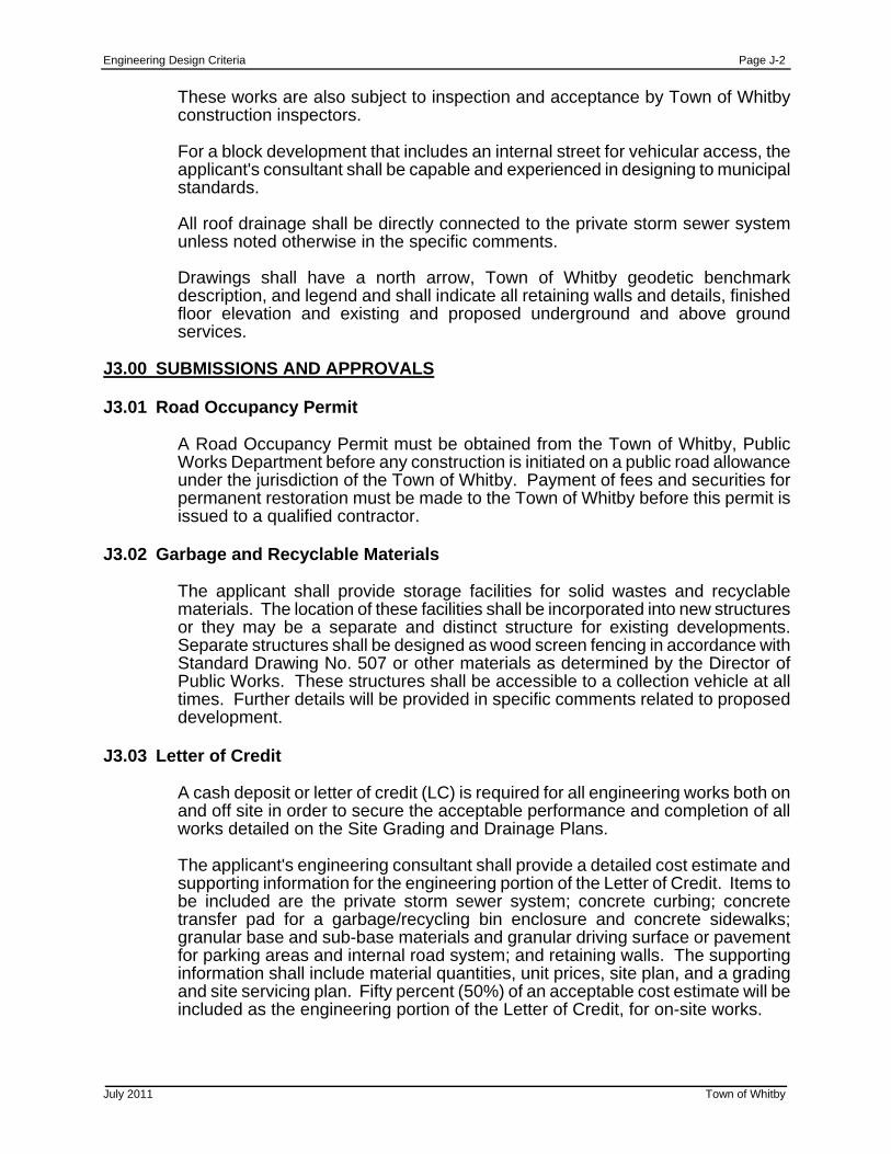
Engineering Design Criteria Page J-2
July 2011 Town of Whitby
These works are also subject to inspection and acceptance by Town of Whitby construction inspectors.
For a block development that includes an internal street for vehicular access, the applicant's consultant shall be capable and experienced in designing to municipal standards.
All roof drainage shall be directly connected to the private storm sewer system unless noted otherwise in the specific comments.
Drawings shall have a north arrow, Town of Whitby geodetic benchmark description, and legend and shall indicate all retaining walls and details, finished floor elevation and existing and proposed underground and above ground services.
J3.00 SUBMISSIONS AND APPROVALS J3.01 Road Occupancy Permit
A Road Occupancy Permit must be obtained from the Town of Whitby, Public Works Department before any construction is initiated on a public road allowance under the jurisdiction of the Town of Whitby. Payment of fees and securities for permanent restoration must be made to the Town of Whitby before this permit is issued to a qualified contractor.
J3.02 Garbage and Recyclable Materials
The applicant shall provide storage facilities for solid wastes and recyclable materials. The location of these facilities shall be incorporated into new structures or they may be a separate and distinct structure for existing developments. Separate structures shall be designed as wood screen fencing in accordance with Standard Drawing No. 507 or other materials as determined by the Director of Public Works. These structures shall be accessible to a collection vehicle at all times. Further details will be provided in specific comments related to proposed development.
J3.03 Letter of Credit
A cash deposit or letter of credit (LC) is required for all engineering works both on and off site in order to secure the acceptable performance and completion of all works detailed on the Site Grading and Drainage Plans.
The applicant's engineering consultant shall provide a detailed cost estimate and supporting information for the engineering portion of the Letter of Credit. Items to be included are the private storm sewer system; concrete curbing; concrete transfer pad for a garbage/recycling bin enclosure and concrete sidewalks; granular base and sub-base materials and granular driving surface or pavement for parking areas and internal road system; and retaining walls. The supporting information shall include material quantities, unit prices, site plan, and a grading and site servicing plan. Fifty percent (50%) of an acceptable cost estimate will be included as the engineering portion of the Letter of Credit, for on-site works.
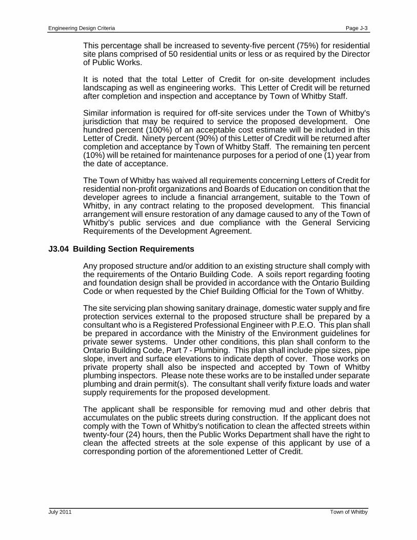
Engineering Design Criteria Page J-3
July 2011 Town of Whitby
This percentage shall be increased to seventy-five percent (75%) for residential site plans comprised of 50 residential units or less or as required by the Director of Public Works. It is noted that the total Letter of Credit for on-site development includes landscaping as well as engineering works. This Letter of Credit will be returned after completion and inspection and acceptance by Town of Whitby Staff.
Similar information is required for off-site services under the Town of Whitby's jurisdiction that may be required to service the proposed development. One hundred percent (100%) of an acceptable cost estimate will be included in this Letter of Credit. Ninety percent (90%) of this Letter of Credit will be returned after completion and acceptance by Town of Whitby Staff. The remaining ten percent (10%) will be retained for maintenance purposes for a period of one (1) year from the date of acceptance.
The Town of Whitby has waived all requirements concerning Letters of Credit for residential non-profit organizations and Boards of Education on condition that the developer agrees to include a financial arrangement, suitable to the Town of Whitby, in any contract relating to the proposed development. This financial arrangement will ensure restoration of any damage caused to any of the Town of Whitby’s public services and due compliance with the General Servicing Requirements of the Development Agreement.
J3.04 Building Section Requirements
Any proposed structure and/or addition to an existing structure shall comply with the requirements of the Ontario Building Code. A soils report regarding footing and foundation design shall be provided in accordance with the Ontario Building Code or when requested by the Chief Building Official for the Town of Whitby.
The site servicing plan showing sanitary drainage, domestic water supply and fire protection services external to the proposed structure shall be prepared by a consultant who is a Registered Professional Engineer with P.E.O. This plan shall be prepared in accordance with the Ministry of the Environment guidelines for private sewer systems. Under other conditions, this plan shall conform to the Ontario Building Code, Part 7 - Plumbing. This plan shall include pipe sizes, pipe slope, invert and surface elevations to indicate depth of cover. Those works on private property shall also be inspected and accepted by Town of Whitby plumbing inspectors. Please note these works are to be installed under separate plumbing and drain permit(s). The consultant shall verify fixture loads and water supply requirements for the proposed development.
The applicant shall be responsible for removing mud and other debris that accumulates on the public streets during construction. If the applicant does not comply with the Town of Whitby's notification to clean the affected streets within twenty-four (24) hours, then the Public Works Department shall have the right to clean the affected streets at the sole expense of this applicant by use of a corresponding portion of the aforementioned Letter of Credit.
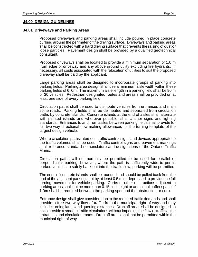
Engineering Design Criteria Page J-4
July 2011 Town of Whitby
J4.00 DESIGN GUIDELINES J4.01 Driveways and Parking Areas
Proposed driveways and parking areas shall include poured in place concrete curbing around the perimeter of the driving surface. Driveways and parking areas shall be constructed with a hard driving surface that prevents the raising of dust or loose particles. Pavement design shall be provided by a qualified geotechnical consultant.
Proposed driveways shall be located to provide a minimum separation of 1.0 m from edge of driveway and any above ground utility excluding fire hydrants. If necessary, all costs associated with the relocation of utilities to suit the proposed driveway shall be paid by the applicant. Large parking areas shall be designed to incorporate groups of parking into parking fields. Parking area design shall use a minimum aisle width within these parking fields of 6. 0m. The maximum aisle length in a parking field shall be 90 m or 30 vehicles. Pedestrian designated routes and areas shall be provided on at least one side of every parking field. Circulation paths shall be used to distribute vehicles from entrances and main spine roads. Parking fields shall be delineated and separated from circulation paths by concrete islands. Concrete islands at the end of aisles shall alternate with painted islands and wherever possible, shall anchor signs and lighting standards. Entrances to and from aisles between parking fields shall provide for full two-way directional flow making allowances for the turning template of the largest design vehicle. Where circulation paths intersect, traffic control signs and devices appropriate to the traffic volumes shall be used. Traffic control signs and pavement markings shall reference standard nomenclature and designations of the Ontario Traffic Manual. Circulation paths will not normally be permitted to be used for parallel or perpendicular parking, however, where the path is sufficiently wide to permit parked vehicles to safely back out into the traffic flow, parking will be permitted. The ends of concrete islands shall be rounded and should be pulled back from the end of the adjacent parking spot by at least 0.5 m or depressed to provide the full turning movement for vehicle parking. Curbs or other obstructions adjacent to parking areas shall not be more than 0.15m in height or additional buffer space of 1.0m shall be required between the parking spot and the obstruction or curb. Entrance design shall give consideration to the required traffic demands and shall provide a free two way flow of traffic from the municipal right of way and may include turning lanes and queuing distances. Drop off areas shall be designed so as to provide a smooth traffic circulations without impeding the flow of traffic at the entrances and circulation roads. Drop off areas shall not be permitted within the municipal right of way.

Engineering Design Criteria Page J-5
July 2011 Town of Whitby
Accessible parking shall be as per Town of Whitby Standard #413 and the Town of Whitby Accessibility Plan. Where possible, the accessible parking shall be located next to the building. The accessible parking must have a 1.5 m to 2.0 m pedestrian sidewalk leading to an accessible building entrance or an unobstructed designated pedestrian crosswalk. A clear horizontal space between a bollard and any other obstacle shall be a minimum of 1.5 m. Required accessible sidewalks and paths shall not be depressed perpendicular to the required direction of travel but shall provide a level path with a maximum combined slope of 8% when measured in any direction and a maximum slope 2% perpendicular to the direction of travel. The design of underground parking shall use the same principles as surface parking. Column locations within underground parking areas shall be designed to minimize conflicts with the turning movements of the design vehicles. Column locations within underground parking areas shall not obstruct the operation of vehicle doors.
J4.02 Maximum and Minimum Grades
Residential driveways - refer to section C6.01.1. Driveway entrances - minimum 2.0% and maximum 8.0%. Service roads - minimum 0.5% and maximum 8.0% (cross fall required). Paved parking areas - minimum 0.5% and maximum 8.0%. Paved commercial parking areas (with possible use of shopping carts) – minimum 0.5% and maximum 3.0%. Sodded areas - maximum 3:1.
J4.03 Retaining Walls
Retaining walls shall be designed by a Professional Engineer. The applicant shall provide the following site specific details that have been prepared by the engineer before any building permit is issued: typical cross section showing minimum and maximum heights, safety railing where exposed height is 0.6 metres or more, method of anchoring safety railing to retaining wall, engineering analysis that retaining walls will support earth loads and live
loads
This Engineer shall certify that the retaining walls have been constructed in accordance with the accepted plans.
J4.04 Urban Standard for Private Internal Street
Any internal street shall be designed and constructed to the following minimum standards Road Width 6.5 m (face of curb to face of curb) 8.5 m (on street parking allowed on one side, F/C to F/C) Concrete Curb and Gutter
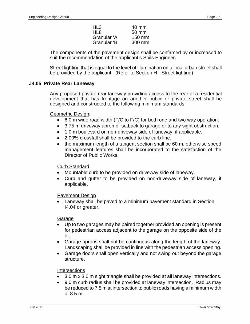
Engineering Design Criteria Page J-6
July 2011 Town of Whitby
HL3 40 mm HL8 50 mm Granular ‘A’ 150 mm Granular ‘B’ 300 mm The components of the pavement design shall be confirmed by or increased to suit the recommendation of the applicant’s Soils Engineer. Street lighting that is equal to the level of illumination on a local urban street shall be provided by the applicant. (Refer to Section H - Street lighting)
J4.05 Private Rear Laneway
Any proposed private rear laneway providing access to the rear of a residential development that has frontage on another public or private street shall be designed and constructed to the following minimum standards: Geometric Design:
6.0 m wide road width (F/C to F/C) for both one and two way operation. 3.75 m driveway apron or setback to garage or to any sight obstruction. 1.0 m boulevard on non-driveway side of laneway, if applicable. 2.00% crossfall shall be provided to the curb line. the maximum length of a tangent section shall be 60 m, otherwise speed
management features shall be incorporated to the satisfaction of the Director of Public Works.
Curb Standard Mountable curb to be provided on driveway side of laneway. Curb and gutter to be provided on non-driveway side of laneway, if
applicable. Pavement Design Laneway shall be paved to a minimum pavement standard in Section
I4.04 or greater. Garage Up to two garages may be paired together provided an opening is present
for pedestrian access adjacent to the garage on the opposite side of the lot.
Garage aprons shall not be continuous along the length of the laneway. Landscaping shall be provided in line with the pedestrian access opening.
Garage doors shall open vertically and not swing out beyond the garage structure.
Intersections 3.0 m x 3.0 m sight triangle shall be provided at all laneway intersections. 9.0 m curb radius shall be provided at laneway intersection. Radius may
be reduced to 7.5 m at intersection to public roads having a minimum width of 8.5 m.
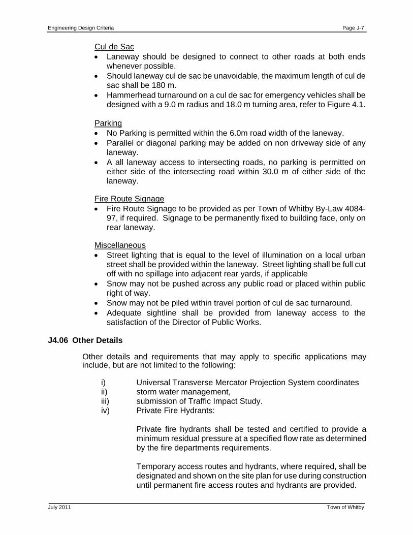
Engineering Design Criteria Page J-7
July 2011 Town of Whitby
Cul de Sac Laneway should be designed to connect to other roads at both ends
whenever possible. Should laneway cul de sac be unavoidable, the maximum length of cul de
sac shall be 180 m. Hammerhead turnaround on a cul de sac for emergency vehicles shall be
designed with a 9.0 m radius and 18.0 m turning area, refer to Figure 4.1. Parking No Parking is permitted within the 6.0m road width of the laneway. Parallel or diagonal parking may be added on non driveway side of any
laneway. A all laneway access to intersecting roads, no parking is permitted on
either side of the intersecting road within 30.0 m of either side of the laneway.
Fire Route Signage Fire Route Signage to be provided as per Town of Whitby By-Law 4084-
97, if required. Signage to be permanently fixed to building face, only on rear laneway.
Miscellaneous Street lighting that is equal to the level of illumination on a local urban
street shall be provided within the laneway. Street lighting shall be full cut off with no spillage into adjacent rear yards, if applicable
Snow may not be pushed across any public road or placed within public right of way.
Snow may not be piled within travel portion of cul de sac turnaround. Adequate sightline shall be provided from laneway access to the
satisfaction of the Director of Public Works.
J4.06 Other Details
Other details and requirements that may apply to specific applications may include, but are not limited to the following:
i) Universal Transverse Mercator Projection System coordinates ii) storm water management, iii) submission of Traffic Impact Study. iv) Private Fire Hydrants: Private fire hydrants shall be tested and certified to provide a
minimum residual pressure at a specified flow rate as determined by the fire departments requirements.
Temporary access routes and hydrants, where required, shall be
designated and shown on the site plan for use during construction until permanent fire access routes and hydrants are provided.
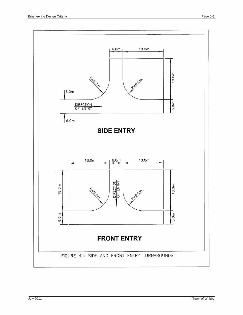
Engineering Design Criteria Page J-8
July 2011 Town of Whitby
Engineering Design Criteria Page J-9
July 2011 Town of Whitby
J5.00 CONSTRUCTION J5.01 Restoration Costs
The applicant will be responsible for all costs to restore all areas within the Town of Whitby public road allowance that are disturbed during the construction of any underground services that are required. Current charges, as amended, for permanent restoration of the public road allowance will apply. See Town of Whitby By-law #6289-10 for restoration rates.
J6.00 RECORD DRAWINGS
Upon completion of construction, and prior to first release of cash deposit or letter of credit securities, the consultant shall provide acceptable “as-built” storm, sanitary and water service connection records to the Director of Public Works for his permanent records.
Where there is a major difference between the design and “as built” data, the consultant is required, in writing, to explain the discrepancy and verify that the "as-built" discrepancy does not adversely affect the intent of the initial design. The final decision regarding deficiency correction or mitigation will be made by the Director of Public Works.
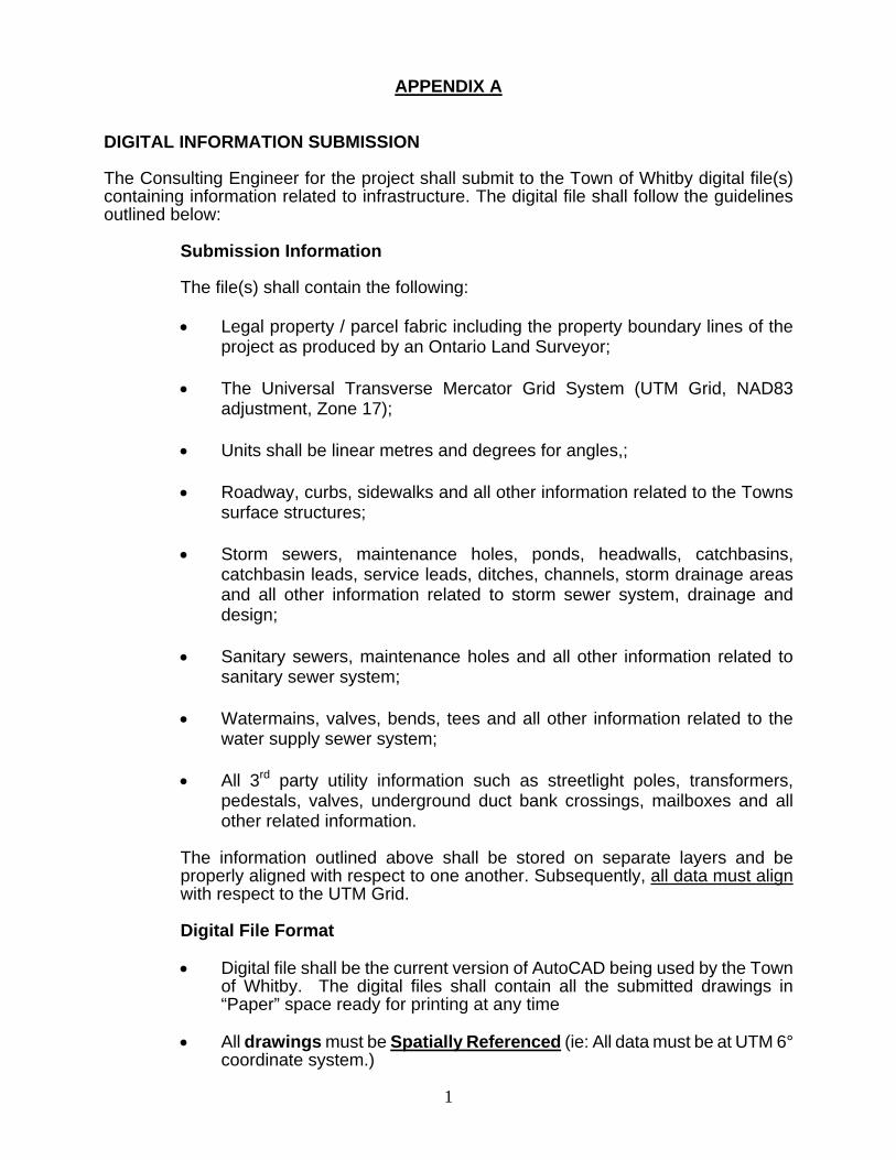
1
APPENDIX A
DIGITAL INFORMATION SUBMISSION The Consulting Engineer for the project shall submit to the Town of Whitby digital file(s) containing information related to infrastructure. The digital file shall follow the guidelines outlined below:
Submission Information The file(s) shall contain the following:
Legal property / parcel fabric including the property boundary lines of the
project as produced by an Ontario Land Surveyor; The Universal Transverse Mercator Grid System (UTM Grid, NAD83
adjustment, Zone 17); Units shall be linear metres and degrees for angles,; Roadway, curbs, sidewalks and all other information related to the Towns
surface structures; Storm sewers, maintenance holes, ponds, headwalls, catchbasins,
catchbasin leads, service leads, ditches, channels, storm drainage areas and all other information related to storm sewer system, drainage and design;
Sanitary sewers, maintenance holes and all other information related to
sanitary sewer system; Watermains, valves, bends, tees and all other information related to the
water supply sewer system; All 3rd party utility information such as streetlight poles, transformers,
pedestals, valves, underground duct bank crossings, mailboxes and all other related information.
The information outlined above shall be stored on separate layers and be properly aligned with respect to one another. Subsequently, all data must align with respect to the UTM Grid.
Digital File Format Digital file shall be the current version of AutoCAD being used by the Town
of Whitby. The digital files shall contain all the submitted drawings in “Paper” space ready for printing at any time
All drawings must be Spatially Referenced (ie: All data must be at UTM 6°
coordinate system.)
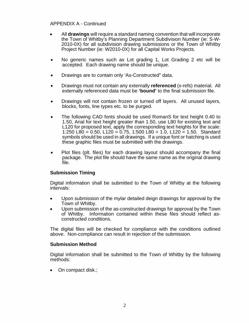
2
APPENDIX A - Continued All drawings will require a standard naming convention that will incorporate
the Town of Whitby’s Planning Department Subdivision Number (ie: S-W-2010-0X) for all subdivision drawing submissions or the Town of Whitby Project Number (ie: W2010-0X) for all Capital Works Projects.
No generic names such as Lot grading 1, Lot Grading 2 etc will be
accepted. Each drawing name should be unique. Drawings are to contain only ‘As-Constructed” data. Drawings must not contain any externally referenced (x-refs) material. All
externally referenced data must be ‘bound’ to the final submission file. Drawings will not contain frozen or turned off layers. All unused layers,
blocks, fonts, line types etc. to be purged. The following CAD fonts should be used RomanS for text height 0.40 to
1.50, Arial for text height greater than 1.50, use L80 for existing text and L120 for proposed text, apply the corresponding text heights for the scale: 1:250 L80 = 0.50, L120 = 0.75, 1:500 L80 = 1.0, L120 = 1.50. Standard symbols should be used in all drawings. If a unique font or hatching is used these graphic files must be submitted with the drawings.
Plot files (plt. files) for each drawing layout should accompany the final
package. The plot file should have the same name as the original drawing file.
Submission Timing Digital information shall be submitted to the Town of Whitby at the following
intervals: Upon submission of the mylar detailed deign drawings for approval by the
Town of Whitby. Upon submission of the as-constructed drawings for approval by the Town
of Whitby. Information contained within these files should reflect as-constructed conditions.
The digital files will be checked for compliance with the conditions outlined
above. Non-compliance can result in rejection of the submission. Submission Method Digital information shall be submitted to the Town of Whitby by the following
methods:
On compact disk.;
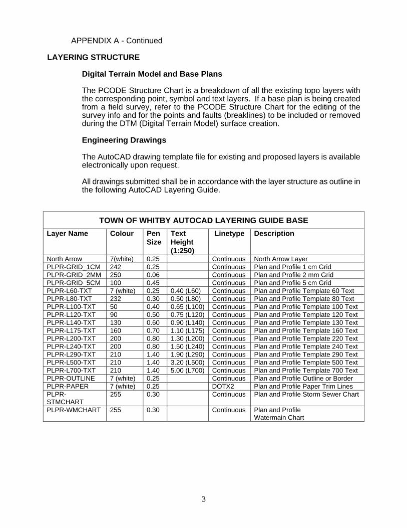
3
APPENDIX A - Continued
LAYERING STRUCTURE
Digital Terrain Model and Base Plans
The PCODE Structure Chart is a breakdown of all the existing topo layers with the corresponding point, symbol and text layers. If a base plan is being created from a field survey, refer to the PCODE Structure Chart for the editing of the survey info and for the points and faults (breaklines) to be included or removed during the DTM (Digital Terrain Model) surface creation. Engineering Drawings The AutoCAD drawing template file for existing and proposed layers is available electronically upon request. All drawings submitted shall be in accordance with the layer structure as outline in the following AutoCAD Layering Guide.
TOWN OF WHITBY AUTOCAD LAYERING GUIDE BASE
Layer Name Colour Pen Size
Text Height (1:250)
Linetype Description
North Arrow 7(white) 0.25 Continuous North Arrow Layer PLPR-GRID_1CM 242 0.25 Continuous Plan and Profile 1 cm Grid PLPR-GRID_2MM 250 0.06 Continuous Plan and Profile 2 mm Grid PLPR-GRID_5CM 100 0.45 Continuous Plan and Profile 5 cm Grid PLPR-L60-TXT 7 (white) 0.25 0.40 (L60) Continuous Plan and Profile Template 60 Text PLPR-L80-TXT 232 0.30 0.50 (L80) Continuous Plan and Profile Template 80 Text PLPR-L100-TXT 50 0.40 0.65 (L100) Continuous Plan and Profile Template 100 Text PLPR-L120-TXT 90 0.50 0.75 (L120) Continuous Plan and Profile Template 120 Text PLPR-L140-TXT 130 0.60 0.90 (L140) Continuous Plan and Profile Template 130 Text PLPR-L175-TXT 160 0.70 1.10 (L175) Continuous Plan and Profile Template 160 Text PLPR-L200-TXT 200 0.80 1.30 (L200) Continuous Plan and Profile Template 220 Text PLPR-L240-TXT 200 0.80 1.50 (L240) Continuous Plan and Profile Template 240 Text PLPR-L290-TXT 210 1.40 1.90 (L290) Continuous Plan and Profile Template 290 Text PLPR-L500-TXT 210 1.40 3.20 (L500) Continuous Plan and Profile Template 500 Text PLPR-L700-TXT 210 1.40 5.00 (L700) Continuous Plan and Profile Template 700 Text PLPR-OUTLINE 7 (white) 0.25 Continuous Plan and Profile Outline or Border PLPR-PAPER 7 (white) 0.25 DOTX2 Plan and Profile Paper Trim Lines PLPR-STMCHART
255 0.30 Continuous Plan and Profile Storm Sewer Chart
PLPR-WMCHART 255 0.30 Continuous Plan and Profile Watermain Chart
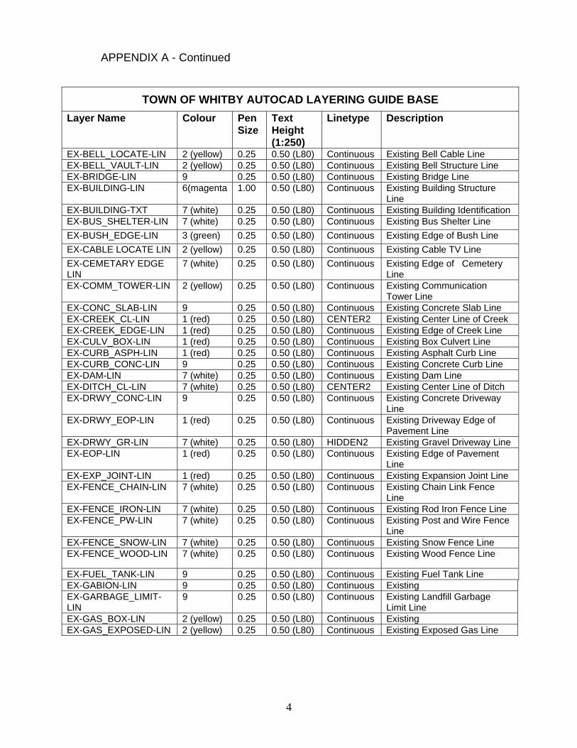
4
APPENDIX A - Continued
TOWN OF WHITBY AUTOCAD LAYERING GUIDE BASE
Layer Name Colour Pen Size
Text Height (1:250)
Linetype Description
EX-BELL_LOCATE-LIN 2 (yellow) 0.25 0.50 (L80) Continuous Existing Bell Cable Line EX-BELL_VAULT-LIN 2 (yellow) 0.25 0.50 (L80) Continuous Existing Bell Structure Line EX-BRIDGE-LIN 9 0.25 0.50 (L80) Continuous Existing Bridge Line EX-BUILDING-LIN 6(magenta 1.00 0.50 (L80) Continuous Existing Building Structure
Line EX-BUILDING-TXT 7 (white) 0.25 0.50 (L80) Continuous Existing Building Identification EX-BUS_SHELTER-LIN 7 (white) 0.25 0.50 (L80) Continuous Existing Bus Shelter Line
EX-BUSH_EDGE-LIN 3 (green) 0.25 0.50 (L80) Continuous Existing Edge of Bush Line
EX-CABLE LOCATE LIN 2 (yellow) 0.25 0.50 (L80) Continuous Existing Cable TV Line
EX-CEMETARY EDGE LIN
7 (white) 0.25 0.50 (L80) Continuous Existing Edge of Cemetery Line
EX-COMM_TOWER-LIN 2 (yellow)
0.25 0.50 (L80) Continuous Existing Communication Tower Line
EX-CONC_SLAB-LIN 9 0.25 0.50 (L80) Continuous Existing Concrete Slab Line EX-CREEK_CL-LIN 1 (red) 0.25 0.50 (L80) CENTER2 Existing Center Line of Creek EX-CREEK_EDGE-LIN 1 (red) 0.25 0.50 (L80) Continuous Existing Edge of Creek Line EX-CULV_BOX-LIN 1 (red) 0.25 0.50 (L80) Continuous Existing Box Culvert Line EX-CURB_ASPH-LIN 1 (red) 0.25 0.50 (L80) Continuous Existing Asphalt Curb Line EX-CURB_CONC-LIN 9 0.25 0.50 (L80) Continuous Existing Concrete Curb Line EX-DAM-LIN 7 (white) 0.25 0.50 (L80) Continuous Existing Dam Line EX-DITCH_CL-LIN 7 (white) 0.25 0.50 (L80) CENTER2 Existing Center Line of Ditch EX-DRWY_CONC-LIN 9 0.25 0.50 (L80) Continuous Existing Concrete Driveway
Line EX-DRWY_EOP-LIN 1 (red) 0.25 0.50 (L80) Continuous Existing Driveway Edge of
Pavement Line EX-DRWY_GR-LIN 7 (white) 0.25 0.50 (L80) HIDDEN2 Existing Gravel Driveway Line EX-EOP-LIN 1 (red) 0.25 0.50 (L80) Continuous Existing Edge of Pavement
Line EX-EXP_JOINT-LIN 1 (red) 0.25 0.50 (L80) Continuous Existing Expansion Joint Line EX-FENCE_CHAIN-LIN 7 (white) 0.25 0.50 (L80) Continuous Existing Chain Link Fence
Line EX-FENCE_IRON-LIN 7 (white) 0.25 0.50 (L80) Continuous Existing Rod Iron Fence Line EX-FENCE_PW-LIN 7 (white) 0.25 0.50 (L80) Continuous Existing Post and Wire Fence
Line EX-FENCE_SNOW-LIN 7 (white) 0.25 0.50 (L80) Continuous Existing Snow Fence Line EX-FENCE_WOOD-LIN 7 (white) 0.25 0.50 (L80) Continuous Existing Wood Fence Line
EX-FUEL_TANK-LIN 9 0.25 0.50 (L80) Continuous Existing Fuel Tank Line EX-GABION-LIN 9 0.25 0.50 (L80) Continuous Existing EX-GARBAGE_LIMIT-LIN
9 0.25 0.50 (L80) Continuous Existing Landfill Garbage Limit Line
EX-GAS_BOX-LIN 2 (yellow) 0.25 0.50 (L80) Continuous Existing EX-GAS_EXPOSED-LIN 2 (yellow) 0.25 0.50 (L80) Continuous Existing Exposed Gas Line
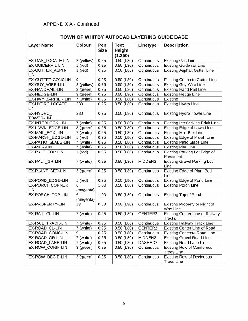
5
APPENDIX A - Continued
TOWN OF WHITBY AUTOCAD LAYERING GUIDE BASE
Layer Name Colour Pen Size
Text Height (1:250)
Linetype Description
EX-GAS_LOCATE-LIN 2 (yellow) 0.25 0.50 (L80) Continuous Existing Gas Line EX-GUIDERAIL-LIN 1 (red) 0.25 0.50 (L80) Continuous Existing Guide rail Line EX-GUTTER_ASPH-LIN
1 (red) 0.25 0.50 (L80) Continuous Existing Asphalt Gutter Line
EX-GUTTER CONCLIN 9 0.25 0.50 (L80) Continuous Existing Concrete Gutter Line EX-GUY_WIRE-LIN 2 (yellow) 0.25 0.50 (L80) Continuous Existing Guy Wire Line EX-HANDRAIL-LIN 3 (green) 0.25 0.50 (L80) Continuous Existing Hand Rail Line EX-HEDGE-LIN 3 (green) 0.25 0.50 (L80) Continuous Existing Hedge Line EX-HWY BARRIER LIN 7 (white) 0.25 0.50 (L80) Continuous Existing EX-HYDRO LOCATE LIN
230 0.25 0.50 (L80) Continuous Existing Hydro Line
EX-HYDRO_ TOWER-LIN
230 0.25 0.50 (L80) Continuous Existing Hydro Tower Line
EX-INTERLOCK-LIN 7 (white) 0.25 0.50 (L80) Continuous Existing Interlocking Brick Line EX-LAWN_EDGE-LIN 3 (green) 0.25 0.50 (L80) Continuous Existing Edge of Lawn Line EX-MAIL_BOX-LIN 7 (white) 0.25 0.50 (L80) Continuous Existing Mail Box Line EX-MARSH_EDGE-LIN 1 (red) 0.25 0.50 (L80) Continuous Existing Edge of Marsh Line EX-PATIO_SLABS-LIN 7 (white) 0.25 0.50 (L80) Continuous Existing Patio Slabs Line EX-PIER-LIN 7 (white) 0.25 0.50 (L80) Continuous Existing Pier Line EX-PKLT_EOP-LIN 1 (red) 0.25 0.50 (L80) Continuous Existing Parking Lot Edge of
Pavement EX-PKLT_GR-LIN 7 (white) 0.25 0.50 (L80) HIDDEN2 Existing Gravel Parking Lot
Line EX-PLANT_BED-LIN 3 (green) 0.25 0.50 (L80) Continuous Existing Edge of Plant Bed
Line EX-POND_EDGE-LIN 1 (red) 0.25 0.50 (L80) Continuous Existing Edge of Pond Line EX-PORCH CORNER LIN
6 (magenta)
1.00 0.50 (L80) Continuous Existing Porch Line
EX-PORCH_TOP-LIN 6 (magenta)
1.00 0.50 (L80) Continuous Existing Top of Porch
EX-PROPERTY-LIN 13 0.50 0.50 (L80) Continuous Existing Property or Right of Way Line
EX-RAIL_CL-LIN 7 (white) 0.25 0.50 (L80) CENTER2 Existing Center Line of Railway Tracks
EX-RAIL_TRACK-LIN 7 (white) 0.25 0.50 (L80) Continuous Existing Railway Track Line EX-ROAD_CL-LIN 7 (white) 0.25 0.50 (L80) CENTER2 Existing Center Line of Road EX-ROAD_CONC-LIN 9 0.25 0.50 (L80) Continuous Existing Concrete Road Line EX-ROAD_GR-LIN 7 (white) 0.25 0.50 (L80) HIDDEN2 Existing Gravel Road Line EX-ROAD_LANE-LIN 7 (white) 0.25 0.50 (L80) DASHED2 Existing Road Lane Line EX-ROW_CONIF-LIN 3 (green) 0.25 0.50 (L80) Continuous Existing Row of Coniferous
Trees Line EX-ROW_DECID-LIN 3 (green) 0.25 0.50 (L80) Continuous Existing Row of Deciduous
Trees Line
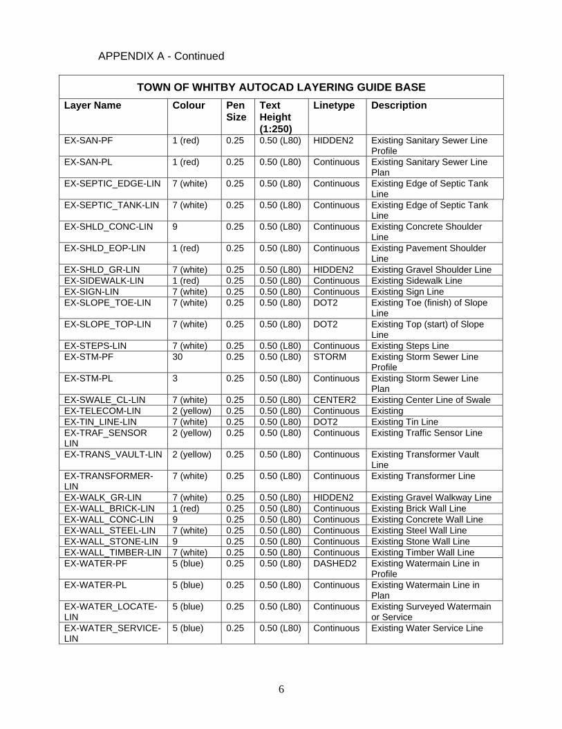
6
APPENDIX A - Continued
TOWN OF WHITBY AUTOCAD LAYERING GUIDE BASE
Layer Name Colour Pen Size
Text Height (1:250)
Linetype Description
EX-SAN-PF 1 (red) 0.25 0.50 (L80) HIDDEN2 Existing Sanitary Sewer Line Profile
EX-SAN-PL 1 (red) 0.25 0.50 (L80) Continuous Existing Sanitary Sewer Line Plan
EX-SEPTIC_EDGE-LIN 7 (white) 0.25 0.50 (L80) Continuous Existing Edge of Septic Tank Line
EX-SEPTIC_TANK-LIN 7 (white) 0.25 0.50 (L80) Continuous Existing Edge of Septic Tank Line
EX-SHLD_CONC-LIN 9 0.25 0.50 (L80) Continuous Existing Concrete Shoulder Line
EX-SHLD_EOP-LIN 1 (red) 0.25 0.50 (L80) Continuous Existing Pavement Shoulder Line
EX-SHLD_GR-LIN 7 (white) 0.25 0.50 (L80) HIDDEN2 Existing Gravel Shoulder Line EX-SIDEWALK-LIN 1 (red) 0.25 0.50 (L80) Continuous Existing Sidewalk Line EX-SIGN-LIN 7 (white) 0.25 0.50 (L80) Continuous Existing Sign Line EX-SLOPE_TOE-LIN 7 (white) 0.25 0.50 (L80) DOT2 Existing Toe (finish) of Slope
Line EX-SLOPE_TOP-LIN 7 (white) 0.25 0.50 (L80) DOT2 Existing Top (start) of Slope
Line EX-STEPS-LIN 7 (white) 0.25 0.50 (L80) Continuous Existing Steps Line EX-STM-PF 30 0.25 0.50 (L80) STORM Existing Storm Sewer Line
Profile EX-STM-PL 3 0.25 0.50 (L80) Continuous Existing Storm Sewer Line
Plan EX-SWALE_CL-LIN 7 (white) 0.25 0.50 (L80) CENTER2 Existing Center Line of Swale EX-TELECOM-LIN 2 (yellow) 0.25 0.50 (L80) Continuous Existing EX-TIN_LINE-LIN 7 (white) 0.25 0.50 (L80) DOT2 Existing Tin Line EX-TRAF_SENSOR LIN
2 (yellow) 0.25 0.50 (L80) Continuous Existing Traffic Sensor Line
EX-TRANS_VAULT-LIN 2 (yellow) 0.25 0.50 (L80) Continuous Existing Transformer Vault Line
EX-TRANSFORMER-LIN
7 (white) 0.25 0.50 (L80) Continuous Existing Transformer Line
EX-WALK_GR-LIN 7 (white) 0.25 0.50 (L80) HIDDEN2 Existing Gravel Walkway Line EX-WALL_BRICK-LIN 1 (red) 0.25 0.50 (L80) Continuous Existing Brick Wall Line EX-WALL_CONC-LIN 9 0.25 0.50 (L80) Continuous Existing Concrete Wall Line EX-WALL_STEEL-LIN 7 (white) 0.25 0.50 (L80) Continuous Existing Steel Wall Line EX-WALL_STONE-LIN 9 0.25 0.50 (L80) Continuous Existing Stone Wall Line EX-WALL_TIMBER-LIN 7 (white) 0.25 0.50 (L80) Continuous Existing Timber Wall Line EX-WATER-PF 5 (blue) 0.25 0.50 (L80) DASHED2 Existing Watermain Line in
Profile EX-WATER-PL 5 (blue) 0.25 0.50 (L80) Continuous Existing Watermain Line in
Plan EX-WATER_LOCATE-LIN
5 (blue) 0.25 0.50 (L80) Continuous Existing Surveyed Watermain or Service
EX-WATER_SERVICE-LIN
5 (blue) 0.25 0.50 (L80) Continuous Existing Water Service Line
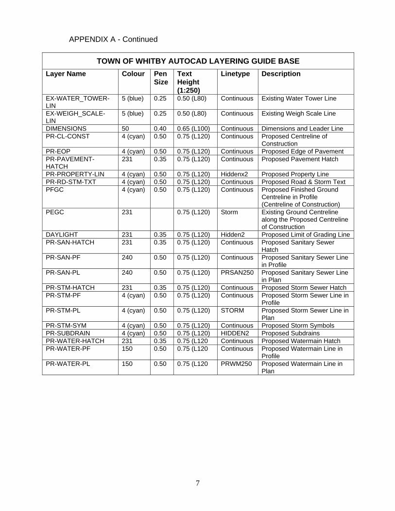
7
APPENDIX A - Continued
TOWN OF WHITBY AUTOCAD LAYERING GUIDE BASE
Layer Name Colour Pen Size
Text Height (1:250)
Linetype Description
EX-WATER_TOWER-LIN
5 (blue) 0.25 0.50 (L80) Continuous Existing Water Tower Line
EX-WEIGH_SCALE-LIN
5 (blue) 0.25 0.50 (L80) Continuous Existing Weigh Scale Line
DIMENSIONS 50 0.40 0.65 (L100) Continuous Dimensions and Leader Line PR-CL-CONST 4 (cyan) 0.50 0.75 (L120) Continuous Proposed Centreline of
Construction PR-EOP 4 (cyan) 0.50 0.75 (L120) Continuous Proposed Edge of Pavement PR-PAVEMENT-HATCH
231 0.35 0.75 (L120) Continuous Proposed Pavement Hatch
PR-PROPERTY-LIN 4 (cyan) 0.50 0.75 (L120) Hiddenx2 Proposed Property Line PR-RD-STM-TXT 4 (cyan) 0.50 0.75 (L120) Continuous Proposed Road & Storm Text PFGC 4 (cyan) 0.50 0.75 (L120) Continuous Proposed Finished Ground
Centreline in Profile (Centreline of Construction)
PEGC 231 0.75 (L120) Storm Existing Ground Centreline along the Proposed Centreline of Construction
DAYLIGHT 231 0.35 0.75 (L120) Hidden2 Proposed Limit of Grading Line PR-SAN-HATCH 231 0.35 0.75 (L120) Continuous Proposed Sanitary Sewer
Hatch PR-SAN-PF 240 0.50 0.75 (L120) Continuous Proposed Sanitary Sewer Line
in Profile PR-SAN-PL 240 0.50 0.75 (L120) PRSAN250 Proposed Sanitary Sewer Line
in Plan PR-STM-HATCH 231 0.35 0.75 (L120) Continuous Proposed Storm Sewer Hatch PR-STM-PF 4 (cyan) 0.50 0.75 (L120) Continuous Proposed Storm Sewer Line in
Profile PR-STM-PL 4 (cyan) 0.50 0.75 (L120) STORM Proposed Storm Sewer Line in
Plan PR-STM-SYM 4 (cyan) 0.50 0.75 (L120) Continuous Proposed Storm Symbols PR-SUBDRAIN 4 (cyan) 0.50 0.75 (L120) HIDDEN2 Proposed Subdrains PR-WATER-HATCH 231 0.35 0.75 (L120 Continuous Proposed Watermain Hatch PR-WATER-PF 150 0.50 0.75 (L120 Continuous Proposed Watermain Line in
Profile PR-WATER-PL 150 0.50 0.75 (L120 PRWM250 Proposed Watermain Line in
Plan
8
APPENDIX A - Continued
Text Styles and Height The AutoCAD Layering Guide gives text height examples for a 1:250 scale drawing. For drawings at 1:500 scale the text heights are multiplied by a factor of 2.
Line Types All custom Town of Whitby line types are available electronically upon request through the Engineering Department. Symbols All Town of Whitby standard symbols are available electronically upon request through the Engineering Department.
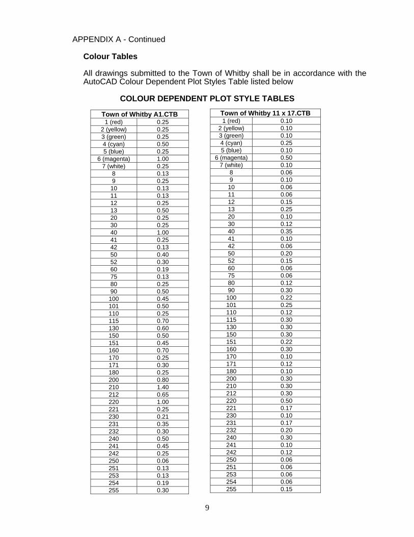
9
APPENDIX A - Continued
Colour Tables All drawings submitted to the Town of Whitby shall be in accordance with the AutoCAD Colour Dependent Plot Styles Table listed below
COLOUR DEPENDENT PLOT STYLE TABLES
Town of Whitby A1.CTB 1 (red) 0.25
2 (yellow) 0.25 3 (green) 0.25 4 (cyan) 0.50 5 (blue) 0.25
6 (magenta) 1.00 7 (white) 0.25
8 0.13 9 0.25 10 0.13 11 0.13 12 0.25 13 0.50 20 0.25 30 0.25 40 1.00 41 0.25 42 0.13 50 0.40 52 0.30 60 0.19 75 0.13 80 0.25 90 0.50
100 0.45 101 0.50 110 0.25 115 0.70 130 0.60 150 0.50 151 0.45 160 0.70 170 0.25 171 0.30 180 0.25 200 0.80 210 1.40 212 0.65 220 1.00 221 0.25 230 0.21 231 0.35 232 0.30 240 0.50 241 0.45 242 0.25 250 0.06 251 0.13 253 0.13 254 0.19 255 0.30
Town of Whitby 11 x 17.CTB 1 (red) 0.10
2 (yellow) 0.10 3 (green) 0.10 4 (cyan) 0.25 5 (blue) 0.10
6 (magenta) 0.50 7 (white) 0.10
8 0.06 9 0.10
10 0.06 11 0.06 12 0.15 13 0.25 20 0.10 30 0.12 40 0.35 41 0.10 42 0.06 50 0.20 52 0.15 60 0.06 75 0.06 80 0.12 90 0.30 100 0.22 101 0.25 110 0.12 115 0.30 130 0.30 150 0.30 151 0.22 160 0.30 170 0.10 171 0.12 180 0.10 200 0.30 210 0.30 212 0.30 220 0.50 221 0.17 230 0.10 231 0.17 232 0.20 240 0.30 241 0.10 242 0.12 250 0.06 251 0.06 253 0.06 254 0.06 255 0.15

1
APPENDIX B ENGINEERING DRAWINGS: ITEMS FOR INCLUSION Drawings forming part of engineering drawing sets as described in Section A shall include, as a minimum, the items listed following:
Plan and Profile Drawings: Miscellaneous: Key Pan Scale(s) Title, revision and signature block Street names, lot and block numbering Lot lines, street lines Lot dimensions North arrow Match lines and chainage Geodetic bench mark information Sidewalk, driveway, street light, hydrant, transformer and community
mailbox locations Watermain and sanitary information for Regional requirements All easements for servicing
Storm Sewer Information: Maintenance holes with side, standard and identification number Pipe diameter, length, grade, material, class and bedding Inverts at maintenance holes Service connections Catchbasins including street, rear yard and ditch inlet 25 year H.G.L. Drop structures Benching details Inlet Control Device Table with ID, Type/Size, Invert Elevation (m), Grate
Elevation (m), Design Head (m), Design Controlled Flow (L/s), 1:5 Year Peak Flow (L/s)
Roadway Information: Existing ground and finished grade profiles Centre line road grade with distances between change in grade Centre line elevations every 25 m and at all low points, high point,
intersections, changes in grade, at P.I., beginning and end of vertical curves
Chainage indication on centre line, every 50 m Beginning and end of horizontal curves
2
APPENDIX B - Continued Roadway Information – Continued:
Curb and gutter Gutter elevations details on bends and cul de sacs at 5 m intervals Pavement structure design with curb type Pavement right of way and boulevard widths Traffic control Grading Plans: (Not applicable to Municipal Projects) Key Plan Scale North arrow Lot numbers, street names Curb, sidewalk transformer, hydrant, street light, driveway and community
mailbox locations Maintenance hole and catchbasins including street, rear yard and ditch inlet Original ground contours Original ground and proposed elevations at all lot corners Road centre line profile data with distances and slope between grade
changes, elevations every 25 m and at all low points, high point, intersections
Centre line chainage indicator every 50 m Lot elevations at all breaks in grade Swale direction and location indicators with arrow Front and rear lot specified grade elevation Retaining wall locations with top and bottom elevations Any sloping Existing trees to be removed and/or preserved
Master Utility Plan: (Not applicable to Municipal Projects) Key Plan Scale North arrow Lot numbers, street names and right of ways/property lines Curb, sidewalk transformer, hydrant, street light, driveway and
community mailbox locations Signature/approval block for each utility, Town of Whitby and Region of
Durham Standard No’s 400 to 403 – Utility Locations Potential tree locations
1
APPENDIX C
The Corporation of the Town of Whitby
Capital Projects - Design Check List and Forms
Index Roadway Design Criteria .....................................................................................3 Pages Intersection Design Criteria…………………………………………………………… 1 Page Form A: 50% Detailed Design Submission / Review Check List .........................5 Pages Form B: 90% Detailed Design Submission / Review Check List .........................4 Pages Form C: Pre-Tender Package Submission / Review Check List .........................3 Pages Form D: Tender Package Check List ..................................................................2 Pages
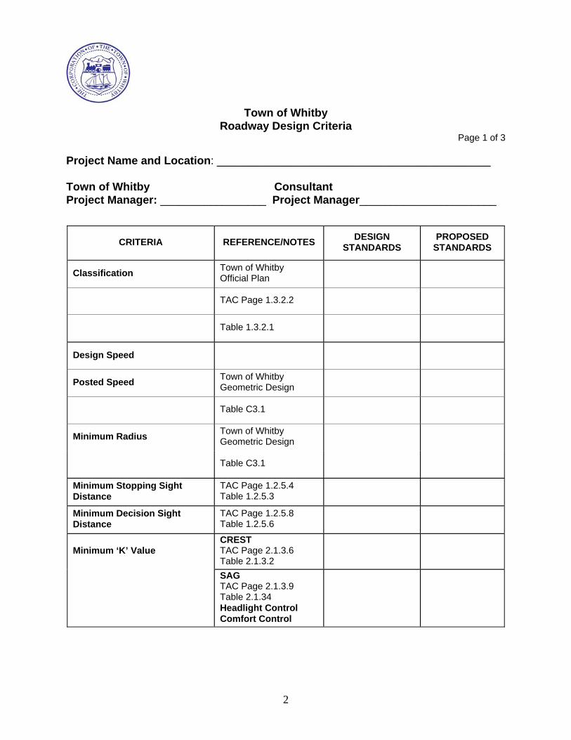
2
Town of Whitby
Roadway Design Criteria Page 1 of 3
Project Name and Location: ____________________________________________ Town of Whitby Consultant Project Manager: _________________ Project Manager______________________
CRITERIA REFERENCE/NOTES DESIGN
STANDARDS PROPOSED
STANDARDS
Classification Town of Whitby Official Plan
TAC Page 1.3.2.2
Table 1.3.2.1
Design Speed
Posted Speed Town of Whitby Geometric Design
Table C3.1
Minimum Radius Town of Whitby Geometric Design
Table C3.1
Minimum Stopping Sight Distance
TAC Page 1.2.5.4 Table 1.2.5.3
Minimum Decision Sight Distance
TAC Page 1.2.5.8 Table 1.2.5.6
Minimum ‘K’ Value CREST TAC Page 2.1.3.6 Table 2.1.3.2
SAG TAC Page 2.1.3.9 Table 2.1.34 Headlight Control Comfort Control
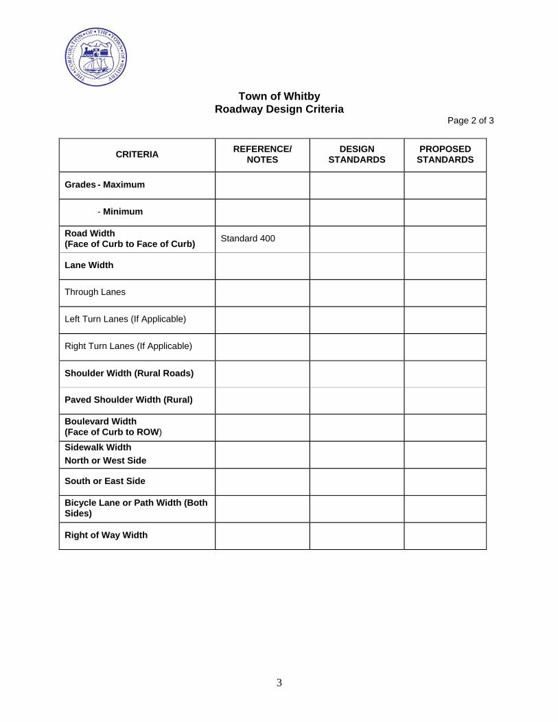
3
Town of Whitby
Roadway Design Criteria Page 2 of 3
CRITERIA REFERENCE/
NOTES DESIGN
STANDARDS PROPOSED
STANDARDS
Grades - Maximum
- Minimum
Road Width (Face of Curb to Face of Curb)
Standard 400
Lane Width
Through Lanes
Left Turn Lanes (If Applicable)
Right Turn Lanes (If Applicable)
Shoulder Width (Rural Roads)
Paved Shoulder Width (Rural)
Boulevard Width (Face of Curb to ROW)
Sidewalk Width
North or West Side
South or East Side
Bicycle Lane or Path Width (Both Sides)
Right of Way Width
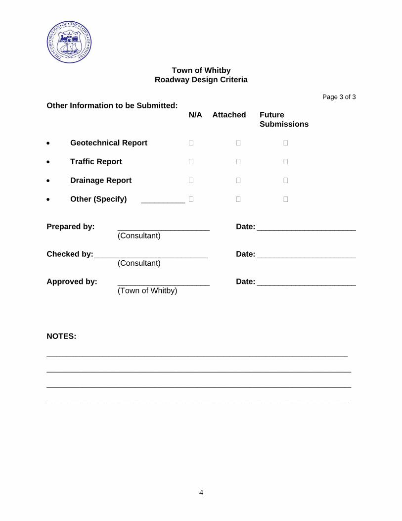
4
Town of Whitby
Roadway Design Criteria
Page 3 of 3 Other Information to be Submitted:
N/A Attached Future Submissions
Geotechnical Report Traffic Report Drainage Report Other (Specify) __________ Prepared by: _____________________ Date: _______________________
(Consultant) Checked by: __________________________ Date: _______________________
(Consultant) Approved by: _____________________ Date: _______________________
(Town of Whitby) NOTES: ____________________________________________________________________________________________ _____________________________________________________________________________________________ _____________________________________________________________________________________________ _____________________________________________________________________________________________

5
Town of Whitby Roadway/Intersection Design Criteria
Page 1 of 1
DETAIL CRITERIAL REFERENCE/NOTES
MAIN ROAD (ARTERIAL) SIDEROADS
(COLLECTORS)
LEG 1 LEG 2 LEG 3 LEG 4
CLASSIFICATION
DESIGN SPEED
STOPPING SIGHT DISTANCE
TAC Pg 1.2.5.4 Table 1.2.5.3.
ROAD TURNING RADIUS
DESIGN VEHICLE
LANE WIDTH – THRU LANES
LEFT TURN
RIGHT TURN
SHOULDER WIDTH
BOULEVARD WIDTH
LEFT TURN LANE TAC Pg 1.2.5.4
Table 1.2.5.3
SET BACK
STORAGE
PARALLEL
TAPER TAC Pg 2.3.8.2
Table 2.3.8.1
RIGHT TURN LANES TAC Pg 2.3.5.5
Figure 2.3.5.3
TAC Pg 2.3.5.2
PARALLEL
TAPER
ISLANDS (MEDIAN) REGION STD S-502
Prepared by: ______________ Checked by:____________ Approved by:____________
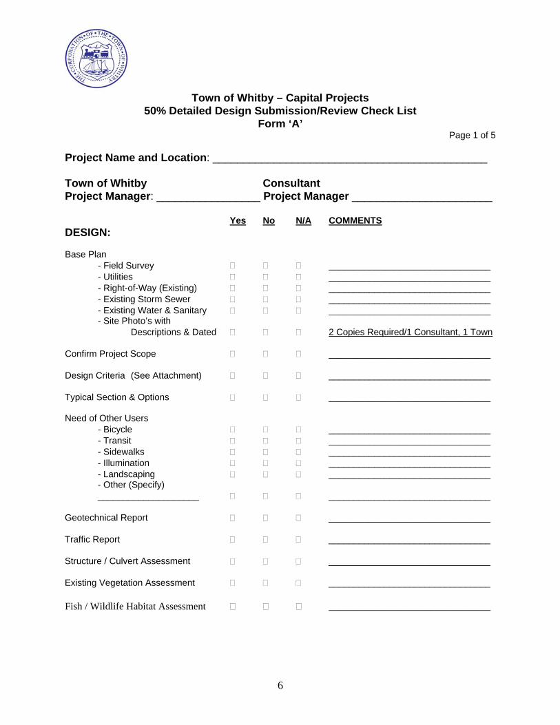
6
Town of Whitby – Capital Projects
50% Detailed Design Submission/Review Check List Form ‘A’
Page 1 of 5
Project Name and Location: _____________________________________________ Town of Whitby Consultant Project Manager: _________________ Project Manager _______________________
Yes No N/A COMMENTS DESIGN: Base Plan
- Field Survey ________________________________ - Utilities ________________________________ - Right-of-Way (Existing) ________________________________ - Existing Storm Sewer ________________________________ - Existing Water & Sanitary ________________________________ - Site Photo’s with
Descriptions & Dated 2 Copies Required/1 Consultant, 1 Town Confirm Project Scope ________________________________ Design Criteria (See Attachment) ________________________________ Typical Section & Options ________________________________ Need of Other Users
- Bicycle ________________________________ - Transit ________________________________ - Sidewalks ________________________________ - Illumination ________________________________ - Landscaping ________________________________ - Other (Specify) ____________________ ________________________________
Geotechnical Report ________________________________ Traffic Report ________________________________ Structure / Culvert Assessment ________________________________ Existing Vegetation Assessment ________________________________ Fish / Wildlife Habitat Assessment ________________________________
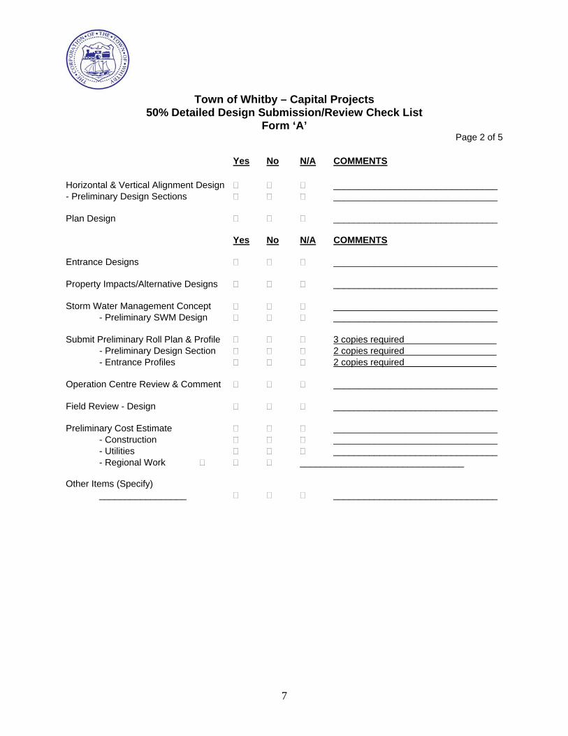
7
Town of Whitby – Capital Projects
50% Detailed Design Submission/Review Check List Form ‘A’
Page 2 of 5
Yes No N/A COMMENTS Horizontal & Vertical Alignment Design ________________________________ - Preliminary Design Sections ________________________________ Plan Design ________________________________
Yes No N/A COMMENTS Entrance Designs ________________________________ Property Impacts/Alternative Designs ________________________________ Storm Water Management Concept ________________________________
- Preliminary SWM Design ________________________________ Submit Preliminary Roll Plan & Profile 3 copies required
- Preliminary Design Section 2 copies required - Entrance Profiles 2 copies required
Operation Centre Review & Comment ________________________________ Field Review - Design ________________________________ Preliminary Cost Estimate ________________________________
- Construction ________________________________ - Utilities ________________________________ - Regional Work ________________________________
Other Items (Specify)
_________________ ________________________________
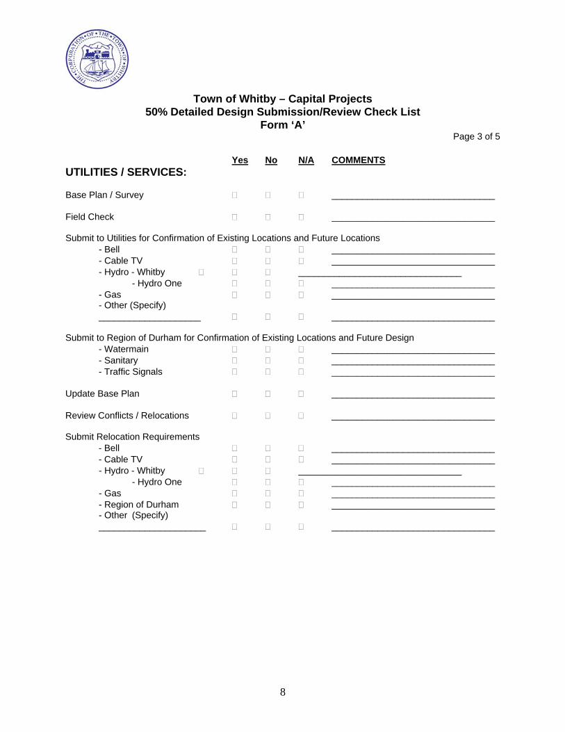
8
Town of Whitby – Capital Projects
50% Detailed Design Submission/Review Check List Form ‘A’
Page 3 of 5
Yes No N/A COMMENTS UTILITIES / SERVICES: Base Plan / Survey ________________________________ Field Check ________________________________ Submit to Utilities for Confirmation of Existing Locations and Future Locations
- Bell ________________________________ - Cable TV ________________________________ - Hydro - Whitby ________________________________
- Hydro One ________________________________ - Gas ________________________________ - Other (Specify) ____________________ ________________________________
Submit to Region of Durham for Confirmation of Existing Locations and Future Design
- Watermain ________________________________ - Sanitary ________________________________ - Traffic Signals ________________________________
Update Base Plan ________________________________ Review Conflicts / Relocations ________________________________ Submit Relocation Requirements
- Bell ________________________________ - Cable TV ________________________________ - Hydro - Whitby ________________________________
- Hydro One ________________________________ - Gas ________________________________ - Region of Durham ________________________________ - Other (Specify) _____________________ ________________________________
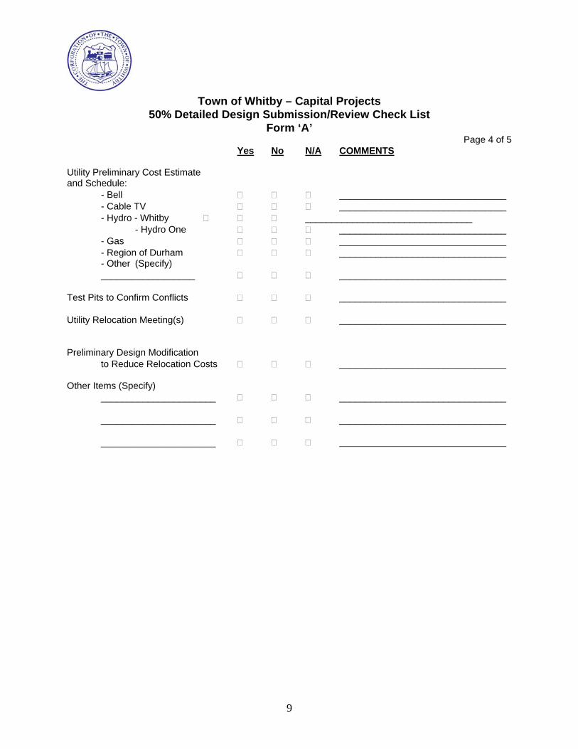
9
Town of Whitby – Capital Projects
50% Detailed Design Submission/Review Check List Form ‘A’
Page 4 of 5 Yes No N/A COMMENTS
Utility Preliminary Cost Estimate and Schedule:
- Bell ________________________________ - Cable TV ________________________________ - Hydro - Whitby ________________________________
- Hydro One ________________________________ - Gas ________________________________ - Region of Durham ________________________________ - Other (Specify) __________________ ________________________________
Test Pits to Confirm Conflicts ________________________________ Utility Relocation Meeting(s) ________________________________ Preliminary Design Modification
to Reduce Relocation Costs ________________________________ Other Items (Specify)
______________________ ________________________________
______________________ ________________________________
______________________ ________________________________

10
Town of Whitby – Capital Projects
50% Detailed Design Submission/Review Check List Form ‘A’
Page 5 of 5 50% REVIEW APPROVAL: Project Manager: ________________________________ Date: __________________________
(Consultant) Project Engineer: _______________________________ Date: __________________________
(Consultant) COMMENTS: TOWN OF WHITBY Public Works Department _____________________________ Date ______________________
(Project Manager) COMMENTS:
Proceed to 90% Design Stage.
Address Comments and Resubmit
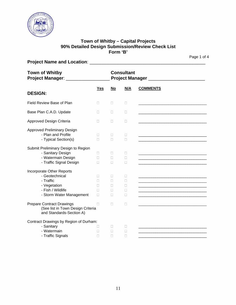
11
Town of Whitby – Capital Projects
90% Detailed Design Submission/Review Check List Form ‘B’
Page 1 of 4 Project Name and Location: _____________________________________________ Town of Whitby Consultant Project Manager: _________________ Project Manager ______________________
Yes No N/A COMMENTS DESIGN: Field Review Base of Plan ________________________________ Base Plan C.A.D. Update ________________________________ Approved Design Criteria ________________________________ Approved Preliminary Design
- Plan and Profile ________________________________ - Typical Section(s) ________________________________
Submit Preliminary Design to Region
- Sanitary Design ________________________________ - Watermain Design ________________________________ - Traffic Signal Design ________________________________
Incorporate Other Reports
- Geotechnical ________________________________ - Traffic ________________________________ - Vegetation ________________________________ - Fish / Wildlife ________________________________ - Storm Water Management ________________________________
Prepare Contract Drawings ________________________________
(See list in Town Design Criteria and Standards-Section A)
Contract Drawings by Region of Durham:
- Sanitary ________________________________ - Watermain ________________________________ - Traffic Signals ________________________________
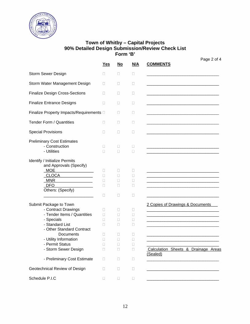
12
Town of Whitby – Capital Projects
90% Detailed Design Submission/Review Check List Form ‘B’
Page 2 of 4 Yes No N/A COMMENTS
Storm Sewer Design ________________________________ Storm Water Management Design ________________________________ Finalize Design Cross-Sections ________________________________ Finalize Entrance Designs ________________________________ Finalize Property Impacts/Requirements ________________________________ Tender Form / Quantities ________________________________ Special Provisions ________________________________ Preliminary Cost Estimates
- Construction ________________________________ - Utilities ________________________________
Identify / Initialize Permits
and Approvals (Specify) MOE ________________________________ CLOCA ________________________________ MNR ________________________________ DFO ________________________________ Others: (Specify) ______________________ ________________________________
Submit Package to Town 2 Copies of Drawings & Documents
- Contract Drawings ________________________________ - Tender Items / Quantities ________________________________ - Specials ________________________________ - Standard List ________________________________ - Other Standard Contract
Documents ________________________________ - Utility Information ________________________________ - Permit Status ________________________________ - Storm Sewer Design Calculation Sheets & Drainage Areas
(Sealed) - Preliminary Cost Estimate ________________________________
Geotechnical Review of Design ________________________________ Schedule P.I.C ________________________________
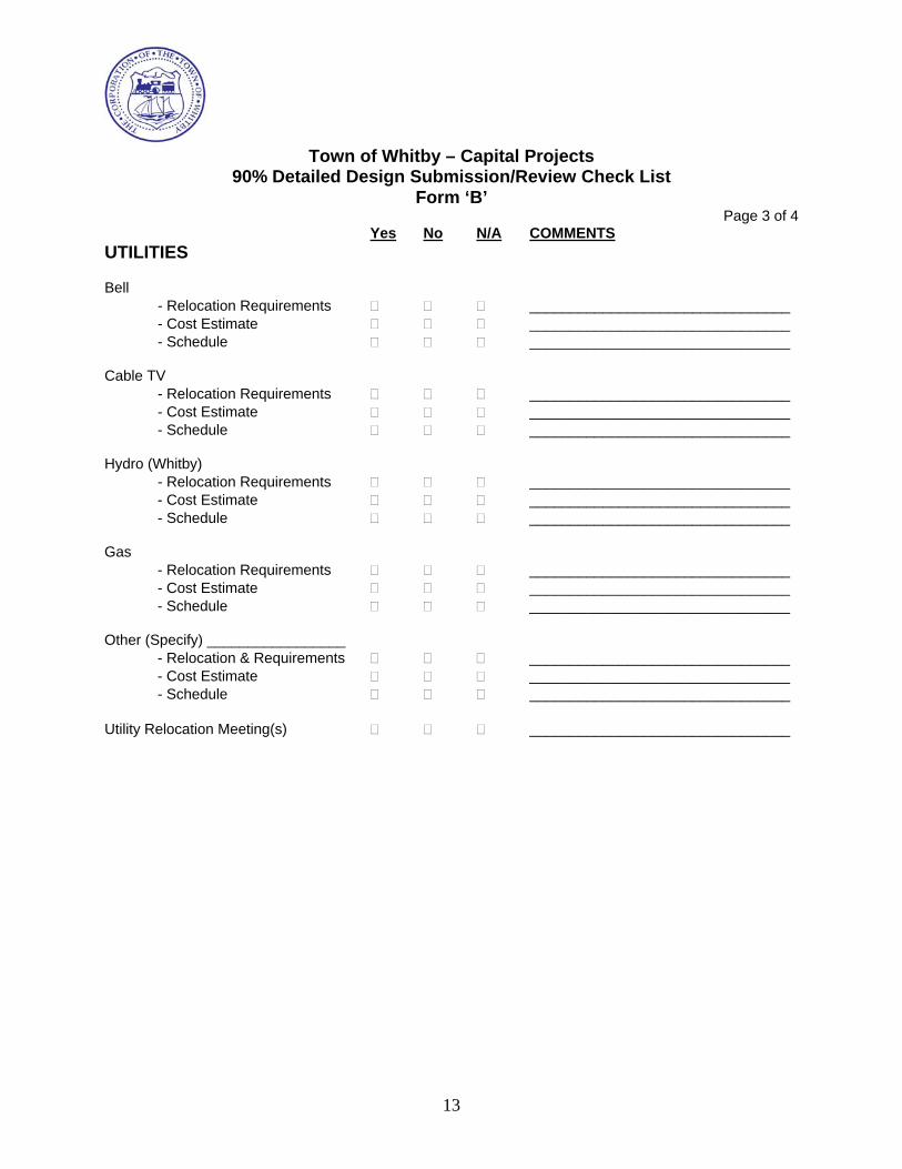
13
Town of Whitby – Capital Projects
90% Detailed Design Submission/Review Check List Form ‘B’
Page 3 of 4 Yes No N/A COMMENTS
UTILITIES Bell
- Relocation Requirements ________________________________ - Cost Estimate ________________________________ - Schedule ________________________________
Cable TV
- Relocation Requirements ________________________________ - Cost Estimate ________________________________ - Schedule ________________________________
Hydro (Whitby)
- Relocation Requirements ________________________________ - Cost Estimate ________________________________ - Schedule ________________________________
Gas
- Relocation Requirements ________________________________ - Cost Estimate ________________________________ - Schedule ________________________________
Other (Specify) _________________
- Relocation & Requirements ________________________________ - Cost Estimate ________________________________ - Schedule ________________________________
Utility Relocation Meeting(s) ________________________________

14
Town of Whitby – Capital Projects
90% Detailed Design Submission/Review Check List Form ‘B’
Page 4 of 4
90% REVIEW APPROVAL: Project Manager: _______________________________ Date: ___________________________
(Consultant) Project Engineer: _______________________________ Date: ___________________________
(Consultant) COMMENTS: TOWN OF WHITBY Public Works Department __________________________ Date: ______________________
(Project Manager) COMMENTS:
Proceed to Pre-Tender Stage.
Address Comments and Resubmit
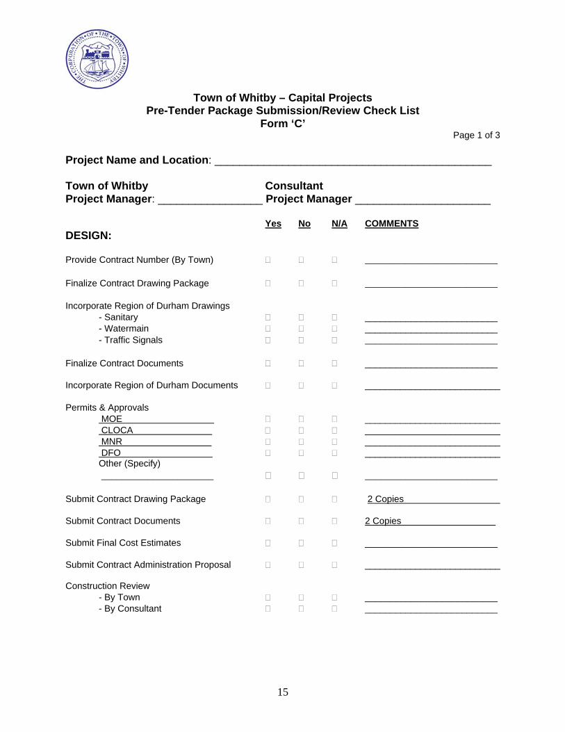
15
Town of Whitby – Capital Projects
Pre-Tender Package Submission/Review Check List Form ‘C’
Page 1 of 3
Project Name and Location: _____________________________________________ Town of Whitby Consultant Project Manager: _________________ Project Manager ______________________
Yes No N/A COMMENTS DESIGN: Provide Contract Number (By Town) __________________________ Finalize Contract Drawing Package __________________________ Incorporate Region of Durham Drawings
- Sanitary __________________________ - Watermain __________________________ - Traffic Signals __________________________
Finalize Contract Documents __________________________
Incorporate Region of Durham Documents ___________________________ Permits & Approvals
MOE ___________________________ CLOCA ___________________________ MNR ___________________________ DFO ___________________________ Other (Specify) ______________________ __________________________
Submit Contract Drawing Package 2 Copies Submit Contract Documents 2 Copies Submit Final Cost Estimates __________________________ Submit Contract Administration Proposal ___________________________ Construction Review
- By Town __________________________ - By Consultant __________________________
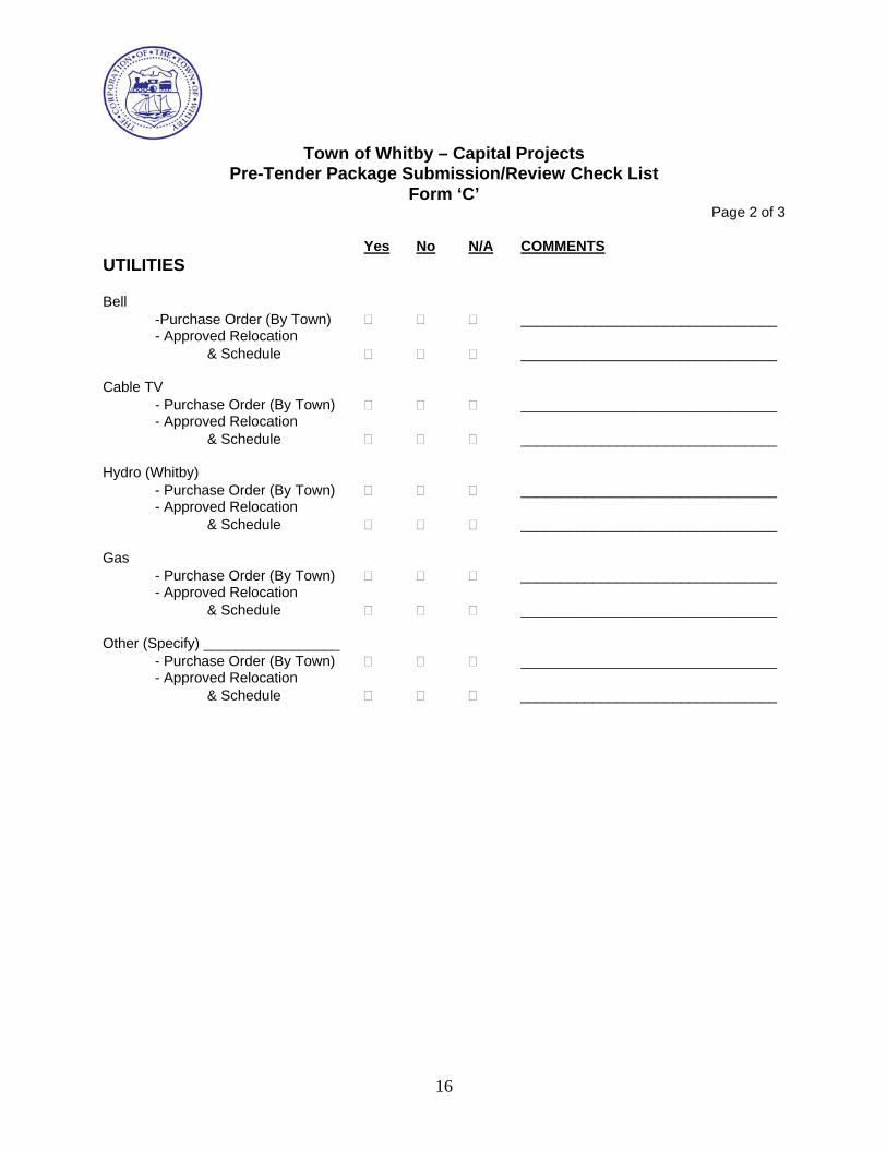
16
Town of Whitby – Capital Projects
Pre-Tender Package Submission/Review Check List Form ‘C’
Page 2 of 3 Yes No N/A COMMENTS
UTILITIES Bell
-Purchase Order (By Town) ________________________________ - Approved Relocation
& Schedule ________________________________ Cable TV
- Purchase Order (By Town) ________________________________ - Approved Relocation
& Schedule ________________________________ Hydro (Whitby)
- Purchase Order (By Town) ________________________________ - Approved Relocation
& Schedule ________________________________ Gas
- Purchase Order (By Town) ________________________________ - Approved Relocation
& Schedule ________________________________ Other (Specify) _________________
- Purchase Order (By Town) ________________________________ - Approved Relocation
& Schedule ________________________________

17
Town of Whitby – Capital Projects
Pre-Tender Package Submission/Review Check List Form ‘C’
Page 3 of 3
PRE-TENDER APPROVAL: Project Manager: _______________________________ Date: ___________________________
(Consultant) Project Engineer: _______________________________ Date: ____________________________
(Consultant) COMMENTS: TOWN OF WHITBY Public Works Department ________________________ Date: ___________________________
(Project Manager) COMMENTS:
Prepare Tender Package
Address Comments and Resubmit
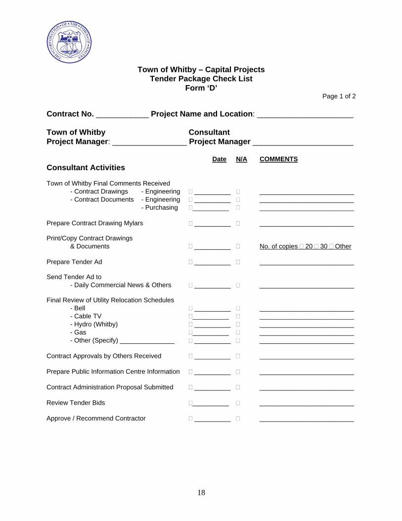
18
Town of Whitby – Capital Projects
Tender Package Check List Form ‘D’
Page 1 of 2 Contract No. ____________ Project Name and Location: ______________________ Town of Whitby Consultant Project Manager: _________________ Project Manager _______________________
Date N/A COMMENTS Consultant Activities Town of Whitby Final Comments Received
- Contract Drawings - Engineering __________ __________________________ - Contract Documents - Engineering __________ __________________________
- Purchasing __________ __________________________ Prepare Contract Drawing Mylars __________ __________________________ Print/Copy Contract Drawings
& Documents __________ No. of copies 20 30 Other Prepare Tender Ad __________ __________________________ Send Tender Ad to
- Daily Commercial News & Others __________ __________________________ Final Review of Utility Relocation Schedules
- Bell __________ __________________________ - Cable TV __________ __________________________ - Hydro (Whitby) __________ __________________________ - Gas __________ __________________________ - Other (Specify) _______________ __________ __________________________
Contract Approvals by Others Received __________ __________________________ Prepare Public Information Centre Information __________ __________________________ Contract Administration Proposal Submitted __________ __________________________ Review Tender Bids __________ __________________________ Approve / Recommend Contractor __________ __________________________
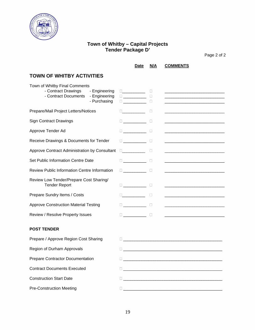
19
Town of Whitby – Capital Projects
Tender Package D’ Page 2 of 2
Date N/A COMMENTS
TOWN OF WHITBY ACTIVITIES Town of Whitby Final Comments
- Contract Drawings - Engineering __________ __________________________ - Contract Documents - Engineering __________ __________________________
- Purchasing __________ __________________________ Prepare/Mail Project Letters/Notices __________ __________________________ Sign Contract Drawings __________ __________________________ Approve Tender Ad __________ __________________________ Receive Drawings & Documents for Tender __________ __________________________ Approve Contract Administration by Consultant __________ __________________________ Set Public Information Centre Date __________ __________________________ Review Public Information Centre Information __________ __________________________ Review Low Tender/Prepare Cost Sharing/
Tender Report __________ __________________________ Prepare Sundry Items / Costs __________ __________________________ Approve Construction Material Testing __________ __________________________ Review / Resolve Property Issues __________ __________________________ POST TENDER Prepare / Approve Region Cost Sharing ___________________________________________ Region of Durham Approvals ___________________________________________ Prepare Contractor Documentation ___________________________________________ Contract Documents Executed ___________________________________________ Construction Start Date ___________________________________________ Pre-Construction Meeting ___________________________________________