section 7 constant strain triangular elements.pptacademic.csuohio.edu/duffy_s/cve_512_7.pdf · ·...
TRANSCRIPT
Section 7: CONSTANT STRAIN TRIANGULAR ELEMENTS
Washkewicz College of Engineering
IntroductionWe have considered “line” elements up to this point, i.e., springs, rods and beams. Grid elements could be added to that category. Line elements have geometric properties associated with the position along the line, for example cross sectional area and moments of inertia. Hence, a local coordinate axis along the line of the element is a necessity.
Now two dimensional planar elements are considered. These elements require two coordinate axes to define the deformation at a position within the element. At first it is quite easy to utilize the global coordinate system for element formulations – at least for constant strain elements. For linear strain elements the use of the global coordinate system is extremely difficult, and we will resort to utilizing a local coordinate system.
With two dimensional elements we will be able to analyze components that can be classified as plane stress problems, or plane strain problems.
The stiffness matrix for the constant strain element is derived and a simple stress problem is considered to illustrate assembling the global stiffness matrix for a component as well as how externally applied tractions are modeled for a component.
1
Washkewicz College of Engineering
Section 7: CONSTANT STRAIN TRIANGULAR ELEMENTS
Discretizing a Linear RegionThe initial objective is the division of a one dimensional region into linear elements and then deriving an equation for each element. The element equation is then generalized so that a continuous piecewise equation can be written along the length of the region. The linear element is used to obtain the approximate solution to the governing differential equation for the problem
02
2
Q
dxydD
The division into elements is straight forward. The elements do not have to be equal in length. For instance consider the cantilever beam subjected to the following temperature profile along the top of the beam
Washkewicz College of Engineering
Section 7: CONSTANT STRAIN TRIANGULAR ELEMENTS
There are rules that guide the placement of nodes. They are
1. Place the nodes closer together in regions where the unknown parameter (in this case temperature throughout the beam) changes rapidly and further apart where the unknown is relatively constant.
2. Place a node wherever there is a stepped change in the differential equation coefficients D and Q. Consider the beam deflection problem where
0MQEID
When there is an abrupt change in the cross sectional area a node is required. In addition nodes are required at the point of application of loads. Consider the uniaxially loaded bar subjected to a uniform temperature all around the surface.
3. Finally place the nodes where you need the value of something.
Washkewicz College of Engineering
Section 7: CONSTANT STRAIN TRIANGULAR ELEMENTS
Discretization
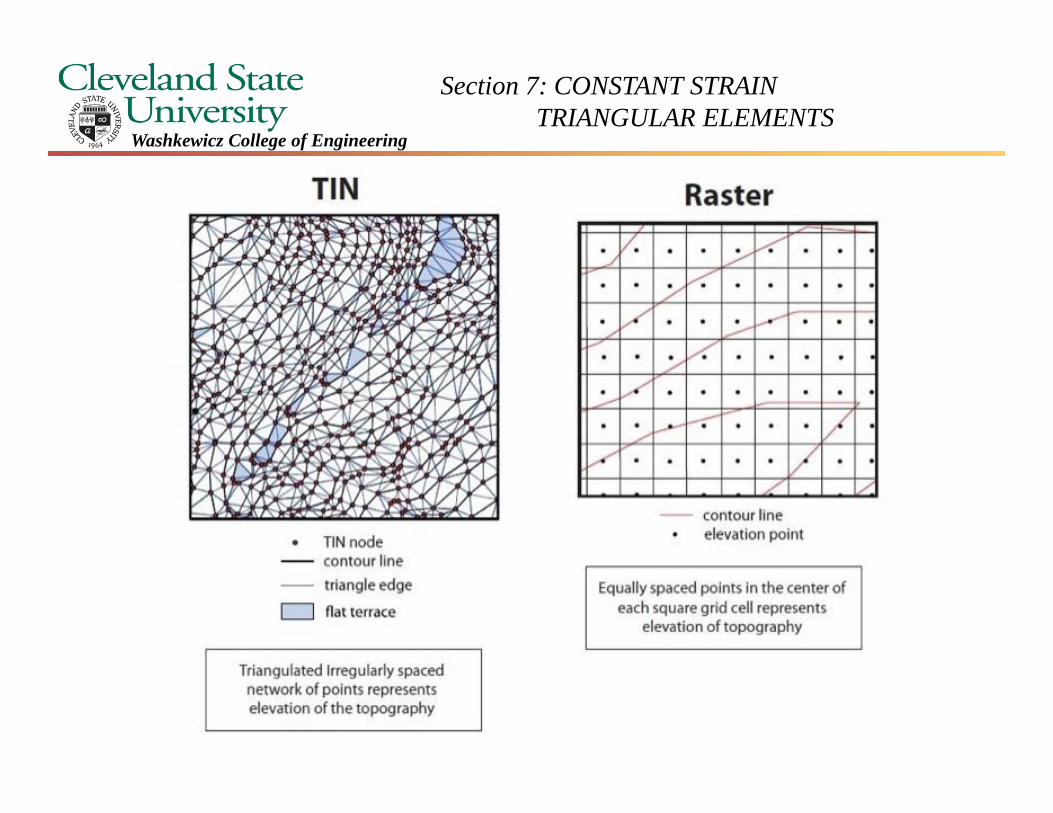
The concepts associated with finite element analysis are strongly tied to the use of meshes (information networks really). The Civil Engineering student has been exposed to information and mesh networks early on in their studies when surveying principles are introduced. The Civil Engineer understands how contour (terrain) plots are generated from grid (raster) field data or from a triangulated irregular network (TIN) of elevation data. Examples of both are depicted on the next overhead.
Washkewicz College of Engineering
Section 7: CONSTANT STRAIN TRIANGULAR ELEMENTS
Washkewicz College of Engineering
Section 7: CONSTANT STRAIN TRIANGULAR ELEMENTS
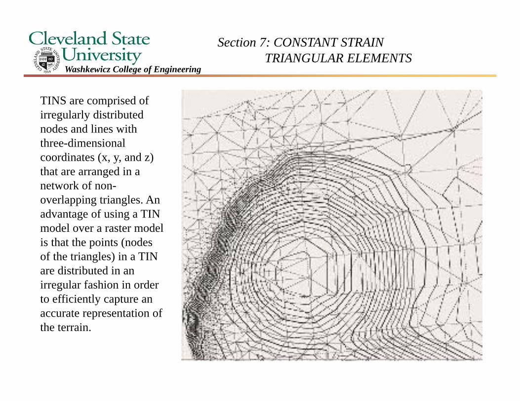
TINS are comprised of irregularly distributed nodes and lines with three-dimensional coordinates (x, y, and z) that are arranged in a network of non-overlapping triangles. An advantage of using a TIN model over a raster model is that the points (nodes of the triangles) in a TIN are distributed in an irregular fashion in order to efficiently capture an accurate representation of the terrain.
Washkewicz College of Engineering
Section 7: CONSTANT STRAIN TRIANGULAR ELEMENTS
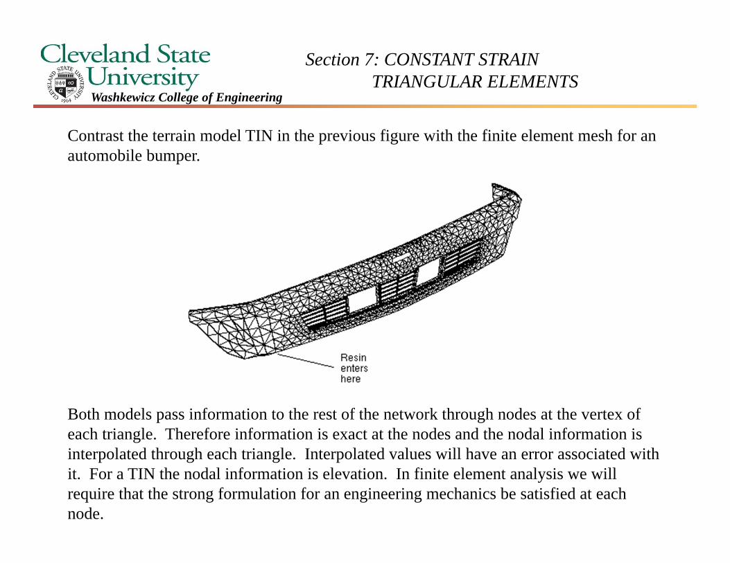
Contrast the terrain model TIN in the previous figure with the finite element mesh for an automobile bumper.
Both models pass information to the rest of the network through nodes at the vertex of each triangle. Therefore information is exact at the nodes and the nodal information is interpolated through each triangle. Interpolated values will have an error associated with it. For a TIN the nodal information is elevation. In finite element analysis we will require that the strong formulation for an engineering mechanics be satisfied at each node.
Section 7: CONSTANT STRAIN TRIANGULAR ELEMENTS
Washkewicz College of Engineering
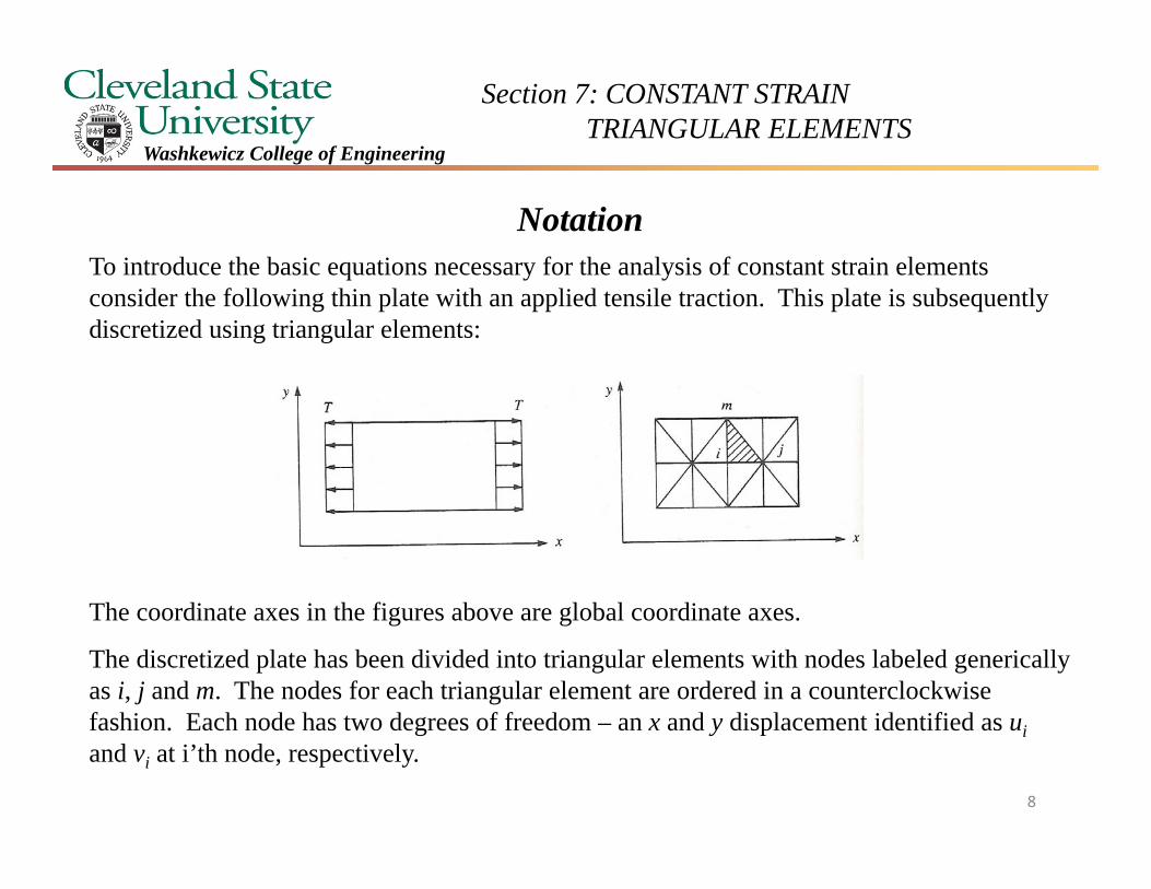
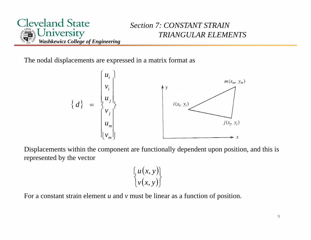
NotationTo introduce the basic equations necessary for the analysis of constant strain elements consider the following thin plate with an applied tensile traction. This plate is subsequently discretized using triangular elements:
The coordinate axes in the figures above are global coordinate axes.
The discretized plate has been divided into triangular elements with nodes labeled generically as i, j and m. The nodes for each triangular element are ordered in a counterclockwise fashion. Each node has two degrees of freedom – an x and y displacement identified as uiand vi at i’th node, respectively.
8
Section 7: CONSTANT STRAIN TRIANGULAR ELEMENTS
Washkewicz College of Engineering
The nodal displacements are expressed in a matrix format as
Displacements within the component are functionally dependent upon position, and this is represented by the vector
For a constant strain element u and v must be linear as a function of position.
m
m
j
j
i
i
vu
v
uvu
d
yxvyxu
,,
9
Section 7: CONSTANT STRAIN TRIANGULAR ELEMENTS
Washkewicz College of Engineering
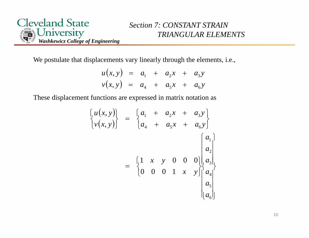
We postulate that displacements vary linearly through the elements, i.e.,
These displacement functions are expressed in matrix notation as
yaxaayxv
yaxaayxu
654
321
,,
6
5
4
3
2
1
654
321
10000001
,,
aaaaaa
yxyx
yaxaayaxaa
yxvyxu
10
Section 7: CONSTANT STRAIN TRIANGULAR ELEMENTS
Washkewicz College of Engineering
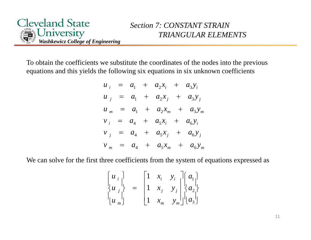
To obtain the coefficients we substitute the coordinates of the nodes into the previous equations and this yields the following six equations in six unknown coefficients
We can solve for the first three coefficients from the system of equations expressed as
mmm
jjj
iii
mmm
jjj
iii
yaxaav
yaxaavyaxaavyaxaau
yaxaauyaxaau
654
654
654
321
321
321
3
2
1
1
11
aaa
yx
yxyx
u
uu
mm
jj
ii
m
j
i
11
Section 7: CONSTANT STRAIN TRIANGULAR ELEMENTS
Washkewicz College of Engineering
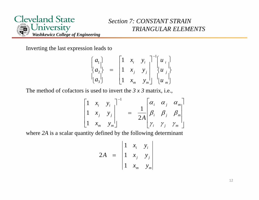
Inverting the last expression leads to
The method of cofactors is used to invert the 3 x 3 matrix, i.e.,
where 2A is a scalar quantity defined by the following determinant
m
j
i
mm
jj
ii
u
uu
yx
yxyx
aaa
1
3
2
1
1
11
mji
mji
mji
mm
jj
ii
Ayx
yxyx
21
1
11
1
mm
jj
ii
yx
yxyx
A
1
11
2
12
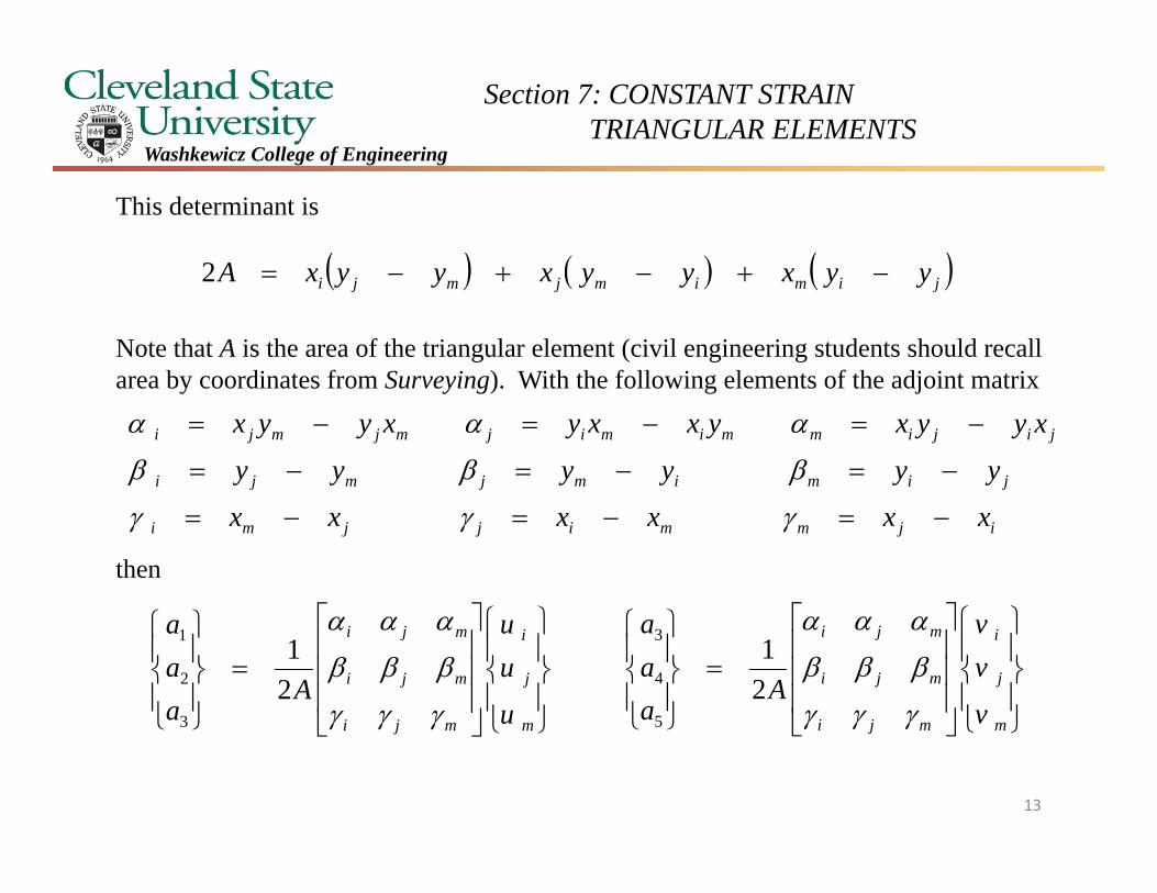
Section 7: CONSTANT STRAIN TRIANGULAR ELEMENTS
Washkewicz College of Engineering
This determinant is
Note that A is the area of the triangular element (civil engineering students should recall area by coordinates from Surveying). With the following elements of the adjoint matrix
then
jimimjmji yyxyyxyyxA 2
ijmmijjmi
jimimjmji
jijimmimijmjmji
xxxxxx
yyyyyy
xyyxyxxyxyyx
m
j
i
mji
mji
mji
u
uu
Aaaa
21
3
2
1
m
j
i
mji
mji
mji
v
vv
Aaaa
21
5
4
3
13
Section 7: CONSTANT STRAIN TRIANGULAR ELEMENTS
Washkewicz College of Engineering
Utilizing the last two matrix expressions we formulate a linear displacement function for the displacement u(x,y) as follows
mmjjii
mmjjii
mmjjii
m
j
i
mji
mji
mji
uuu
uuu
uuu
Ayx
u
uu
Ayx
aaa
yx
yaxaayxu
211
211
1
,
3
2
1
321
14
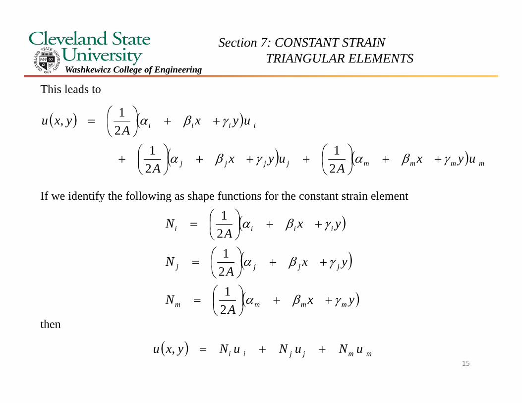
Section 7: CONSTANT STRAIN TRIANGULAR ELEMENTS
Washkewicz College of Engineering
This leads to
If we identify the following as shape functions for the constant strain element
then
mmmmjjjj
iiii
uyxA
uyxA
uyxA
yxu
21
21
21,
yxA
N
yxA
N
yxA
N
mmmm
jjjj
iiii
21
21
21
mmjjii uNuNuNyxu ,15
Section 7: CONSTANT STRAIN TRIANGULAR ELEMENTS
Washkewicz College of Engineering
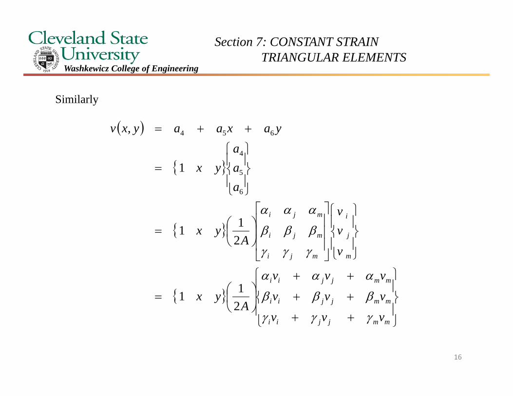
Similarly
mmjjii
mmjjii
mmjjii
m
j
i
mji
mji
mji
vvv
vvv
vvv
Ayx
v
vv
Ayx
aaa
yx
yaxaayxv
211
211
1
,
6
5
4
654
16
Section 7: CONSTANT STRAIN TRIANGULAR ELEMENTS
Washkewicz College of Engineering
and
Once again
These are the same shape functions developed for u(x,y). Using the shape function notation leads to
mmmmjjjj
iiii
vyxA
vyxA
vyxA
yxv
21
21
21,
yxA
N
yxA
N
yxA
N
mmmm
jjjj
iiii
21
21
21
mmjjii vNvNvNyxv , 17
Section 7: CONSTANT STRAIN TRIANGULAR ELEMENTS
Washkewicz College of Engineering
m
m
j
j
i
i
mji
mji
mmjjii
mmjjii
vu
v
uvu
NNN
NNN
vNvNvN
uNuNuN
yxvyxu
000
000
,,
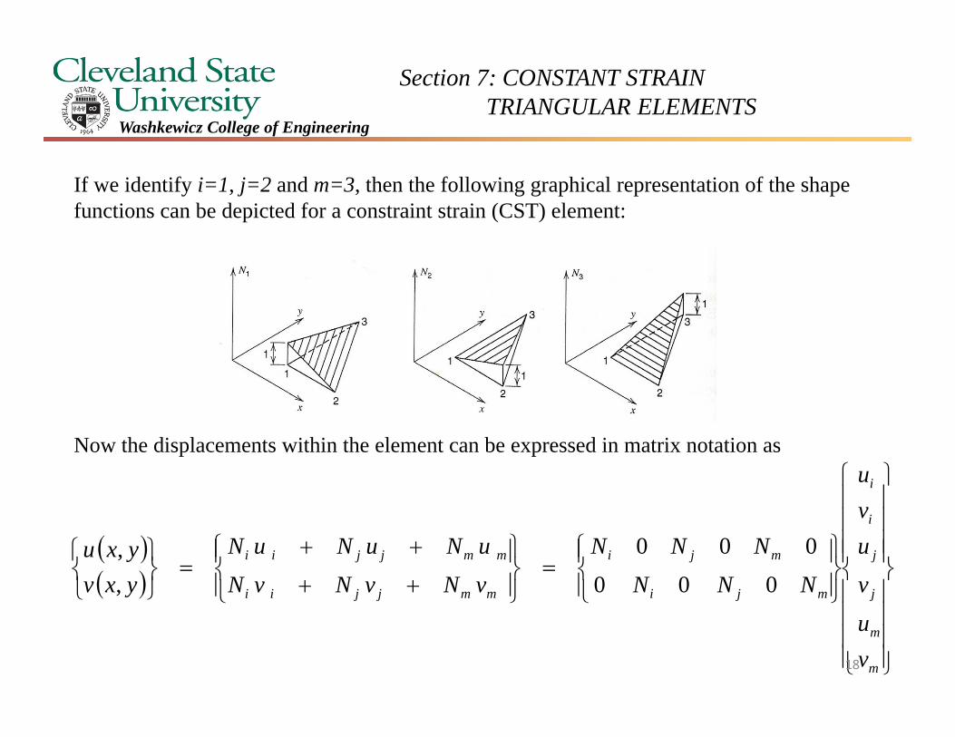
If we identify i=1, j=2 and m=3, then the following graphical representation of the shape functions can be depicted for a constraint strain (CST) element:
Now the displacements within the element can be expressed in matrix notation as
18
Section 7: CONSTANT STRAIN TRIANGULAR ELEMENTS
Washkewicz College of Engineering
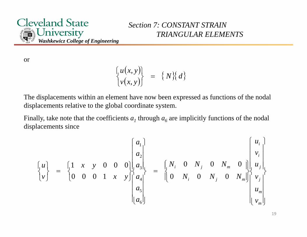
or
The displacements within an element have now been expressed as functions of the nodal displacements relative to the global coordinate system.
Finally, take note that the coefficients a1 through a6 are implicitly functions of the nodal displacements since
dN
yxvyxu
,,
m
m
j
j
i
i
mji
mji
vu
v
uvu
NNN
NNN
aaaaaa
yxyx
vu
000
000
10000001
6
5
4
3
2
1
19
Section 7: CONSTANT STRAIN TRIANGULAR ELEMENTS
Washkewicz College of Engineering
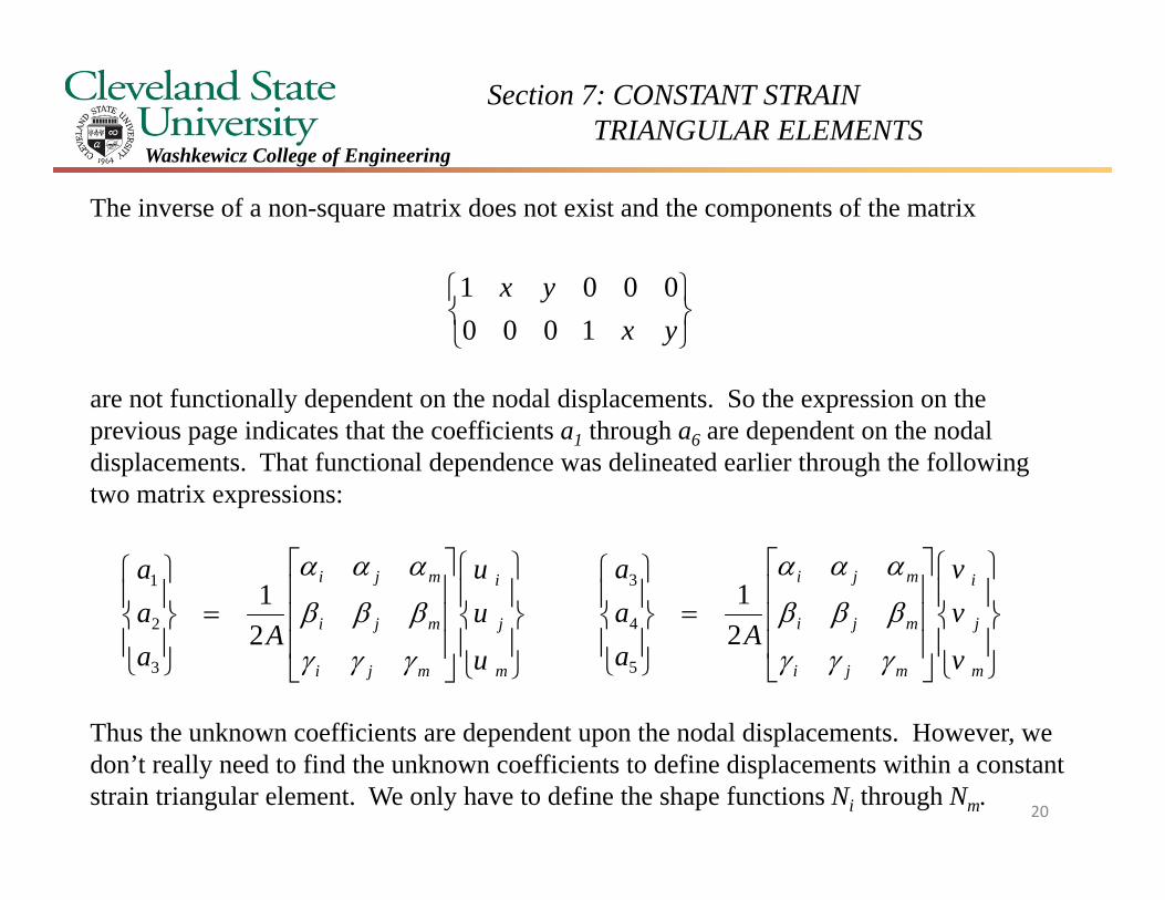
The inverse of a non-square matrix does not exist and the components of the matrix
are not functionally dependent on the nodal displacements. So the expression on the previous page indicates that the coefficients a1 through a6 are dependent on the nodal displacements. That functional dependence was delineated earlier through the following two matrix expressions:
Thus the unknown coefficients are dependent upon the nodal displacements. However, we don’t really need to find the unknown coefficients to define displacements within a constant strain triangular element. We only have to define the shape functions Ni through Nm.
yxyx
10000001
m
j
i
mji
mji
mji
u
uu
Aaaa
21
3
2
1
m
j
i
mji
mji
mji
v
vv
Aaaa
21
5
4
3
20
Section 7: CONSTANT STRAIN TRIANGULAR ELEMENTS
Washkewicz College of Engineering
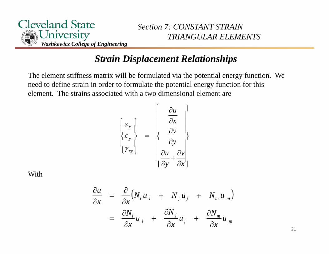
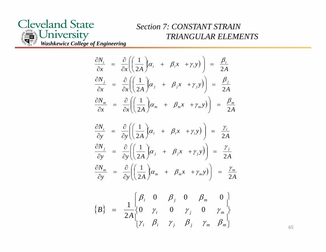
Strain Displacement Relationships The element stiffness matrix will be formulated via the potential energy function. We need to define strain in order to formulate the potential energy function for this element. The strains associated with a two dimensional element are
With
xv
yu
yvxu
xy
y
x
mm
jj
ii
mmjjii
ux
Nux
Nu
xN
uNuNuNxx
u
21

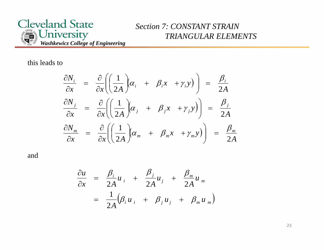
Section 7: CONSTANT STRAIN TRIANGULAR ELEMENTS
Washkewicz College of Engineering
this leads to
and
A
yxAxx
N
Ayx
AxxN
Ayx
AxxN
mmmm
m
jjjj
j
iiii
i
221
221
221
mmjjii
mm
jj
ii
uuuA
uA
uA
uAx
u
21
222
22
Section 7: CONSTANT STRAIN TRIANGULAR ELEMENTS
Washkewicz College of Engineering
this leads to
and
A
yxAxx
N
Ayx
AxxN
Ayx
AxxN
mmmm
m
jjjj
j
iiii
i
221
221
221
mmjjii
mm
jj
ii
uuuA
uA
uA
uAx
u
21
222
23
Section 7: CONSTANT STRAIN TRIANGULAR ELEMENTS
Washkewicz College of Engineering
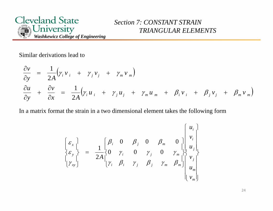
Similar derivations lead to
In a matrix format the strain in a two dimensional element takes the following form
mmjjiimmjjii
mmjjii
vvvuuuAx
vyu
vvvAy
v
21
21
m
m
j
j
i
i
mmjjii
mji
mji
xy
y
x
vu
v
uvu
A
000
000
21
24
Section 7: CONSTANT STRAIN TRIANGULAR ELEMENTS
Washkewicz College of Engineering
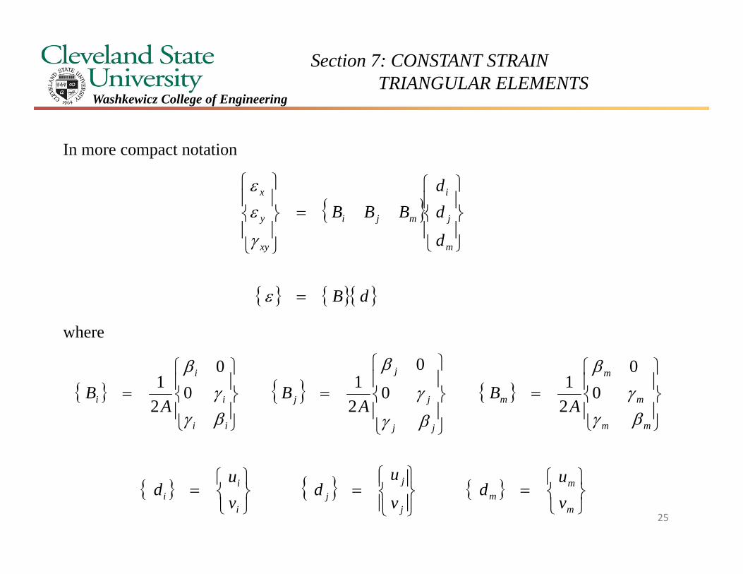
In more compact notation
where
dB
d
dd
BBB
m
j
i
mji
xy
y
x
mm
m
m
m
jj
j
j
j
ii
i
i
i AB
AB
AB
0
0
210
0
210
0
21
m
mm
j
jj
i
ii v
ud
v
ud
vu
d25
Section 7: CONSTANT STRAIN TRIANGULAR ELEMENTS
Washkewicz College of Engineering
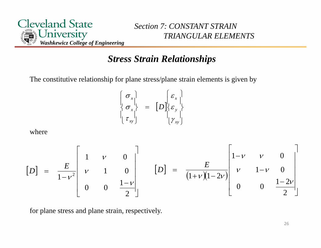
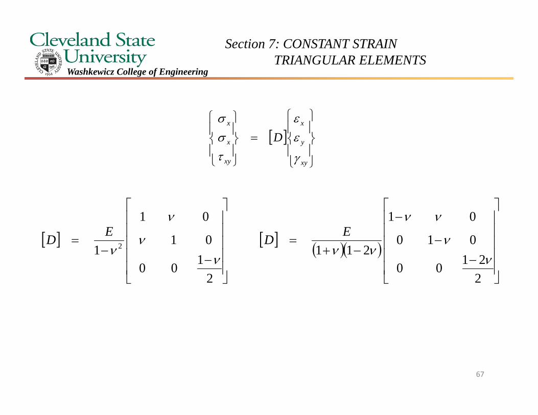
Stress Strain Relationships
The constitutive relationship for plane stress/plane strain elements is given by
where
for plane stress and plane strain, respectively.
xy
y
x
xy
x
x
D
2100
01
01
1 2
ED
26
22100
01
01
211
ED
Section 7: CONSTANT STRAIN TRIANGULAR ELEMENTS
Washkewicz College of Engineering
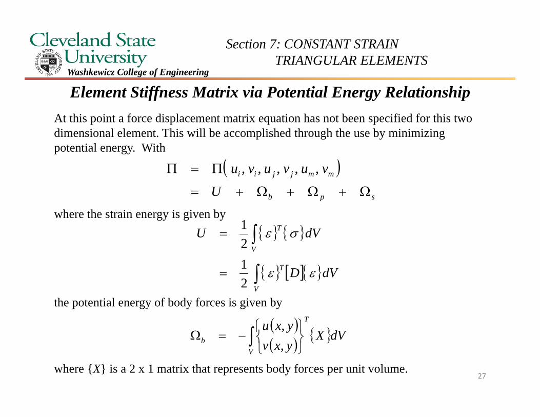
Element Stiffness Matrix via Potential Energy RelationshipAt this point a force displacement matrix equation has not been specified for this two dimensional element. This will be accomplished through the use by minimizing potential energy. With
where the strain energy is given by
the potential energy of body forces is given by
where {X} is a 2 x 1 matrix that represents body forces per unit volume.
spb
mmjjii
U
vuvuvu
,,,,,
V
T
V
T
dVD
dVU
2121
V
T
b dVXyxvyxu
,,
27
Section 7: CONSTANT STRAIN TRIANGULAR ELEMENTS
Washkewicz College of Engineering
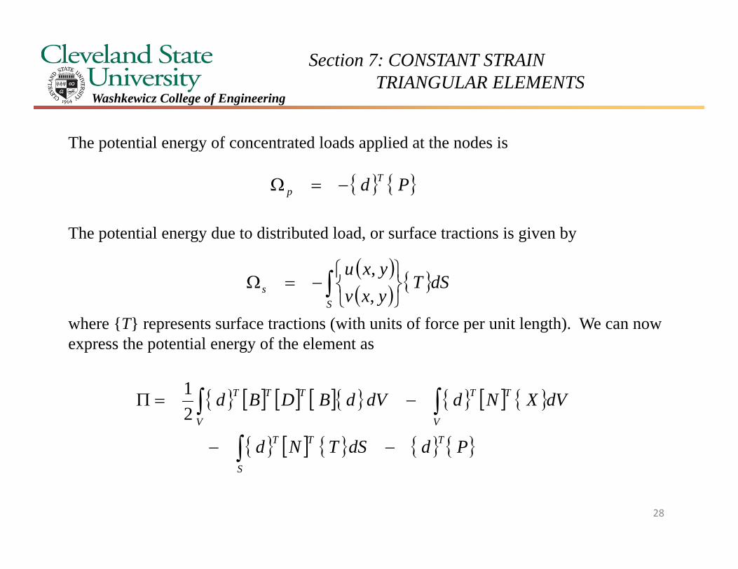
The potential energy of concentrated loads applied at the nodes is
The potential energy due to distributed load, or surface tractions is given by
where {T} represents surface tractions (with units of force per unit length). We can now express the potential energy of the element as
Pd Tp
S
s dSTyxvyxu
,,
PddSTNd
dVXNddVdBDBd
T
S
TT
V
TT
V
TTT
21
28
Section 7: CONSTANT STRAIN TRIANGULAR ELEMENTS
Washkewicz College of Engineering
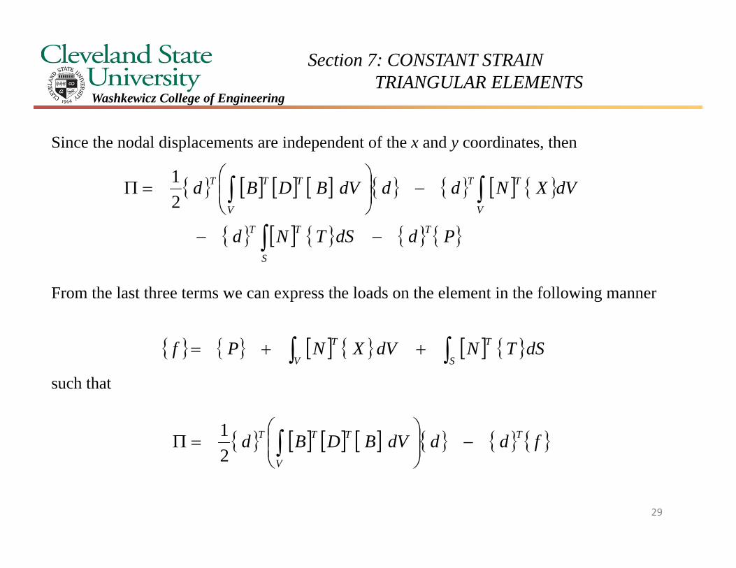
Since the nodal displacements are independent of the x and y coordinates, then
From the last three terms we can express the loads on the element in the following manner
such that
PddSTNd
dVXNdddVBDBd
T
S
TT
V
TT
V
TTT
21
S
T
V
T dSTNdVXNPf
fdddVBDBd T
V
TTT
2
1
29

Section 7: CONSTANT STRAIN TRIANGULAR ELEMENTS
Washkewicz College of Engineering
Taking the partial derivative of the potential energy with respect to the nodal displacements leads to
Setting this expression equal to zero leads to
This is the relevant force displacement relationship where the element stiffness matrix is
fddVBDB
fdddVBDBddd
V
TT
T
V
TTT
21
dkddVBDBf
fddVBDB
V
TT
V
TT
0
V
TT dVBDBk30
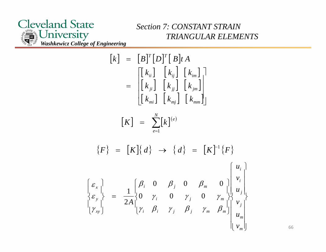
Section 7: CONSTANT STRAIN TRIANGULAR ELEMENTS
Washkewicz College of Engineering
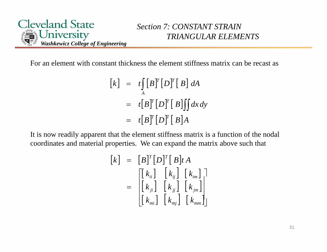
For an element with constant thickness the element stiffness matrix can be recast as
It is now readily apparent that the element stiffness matrix is a function of the nodal coordinates and material properties. We can expand the matrix above such that
ABDBt
dydxBDBt
dABDBtk
TT
TT
A
TT
mmmjmi
jmjjji
imijii
TT
kkk
kkk
kkk
AtBDBk
31
Section 7: CONSTANT STRAIN TRIANGULAR ELEMENTS
Washkewicz College of Engineering
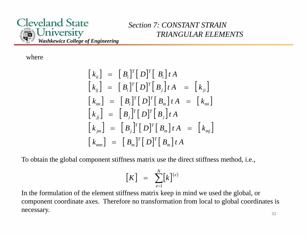
where
AtBDBk
kAtBDBk
AtBDBk
kAtBDBk
kAtBDBk
AtBDBk
mTT
mmm
mjmTT
jjm
jTT
jjj
mimTT
iim
jijTT
iij
iTT
iii
To obtain the global component stiffness matrix use the direct stiffness method, i.e.,
In the formulation of the element stiffness matrix keep in mind we used the global, or component coordinate axes. Therefore no transformation from local to global coordinates is necessary.
N
e
ekK1
32

Section 7: CONSTANT STRAIN TRIANGULAR ELEMENTS
Washkewicz College of Engineering
In class example
33
Section 7: CONSTANT STRAIN TRIANGULAR ELEMENTS
Washkewicz College of Engineering
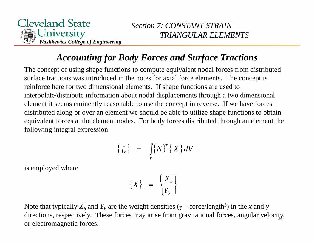
Accounting for Body Forces and Surface TractionsThe concept of using shape functions to compute equivalent nodal forces from distributed surface tractions was introduced in the notes for axial force elements. The concept is reinforce here for two dimensional elements. If shape functions are used to interpolate/distribute information about nodal displacements through a two dimensional element it seems eminently reasonable to use the concept in reverse. If we have forces distributed along or over an element we should be able to utilize shape functions to obtain equivalent forces at the element nodes. For body forces distributed through an element the following integral expression
is employed where
Note that typically Xb and Yb are the weight densities ( force/length3) in the x and ydirections, respectively. These forces may arise from gravitational forces, angular velocity, or electromagnetic forces.
dVXNfV
Tb
b
b
YX
X
34
Section 7: CONSTANT STRAIN TRIANGULAR ELEMENTS
Washkewicz College of Engineering
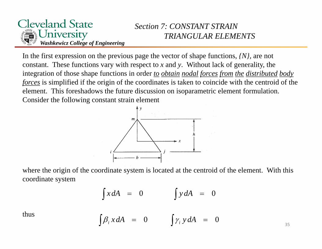
In the first expression on the previous page the vector of shape functions, {N}, are not constant. These functions vary with respect to x and y. Without lack of generality, the integration of those shape functions in order to obtain nodal forces from the distributed bodyforces is simplified if the origin of the coordinates is taken to coincide with the centroid of the element. This foreshadows the future discussion on isoparametric element formulation. Consider the following constant strain element
where the origin of the coordinate system is located at the centroid of the element. With this coordinate system
thus
00 dAydAx
00 dAydAx ii 35
Section 7: CONSTANT STRAIN TRIANGULAR ELEMENTS
Washkewicz College of Engineering
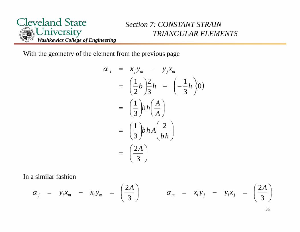
With the geometry of the element from the previous page
In a similar fashion
32
231
31
031
32
21
A
hbAhb
AAhb
hhb
xyyx mjmji
32
32 AxyyxAyxxy jijimmimij
36
Section 7: CONSTANT STRAIN TRIANGULAR ELEMENTS
Washkewicz College of Engineering
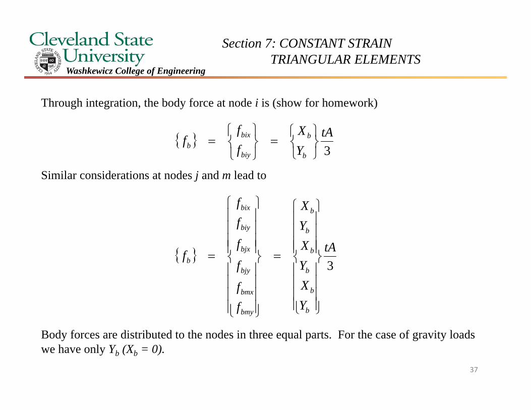
Through integration, the body force at node i is (show for homework)
Similar considerations at nodes j and m lead to
Body forces are distributed to the nodes in three equal parts. For the case of gravity loads we have only Yb (Xb = 0).
3tA
YX
ff
fb
b
biy
bixb
3tA
YXYXYX
ff
f
f
ff
f
b
b
b
b
b
b
bmy
bmx
bjy
bjx
biy
bix
b
37
Section 7: CONSTANT STRAIN TRIANGULAR ELEMENTS
Washkewicz College of Engineering
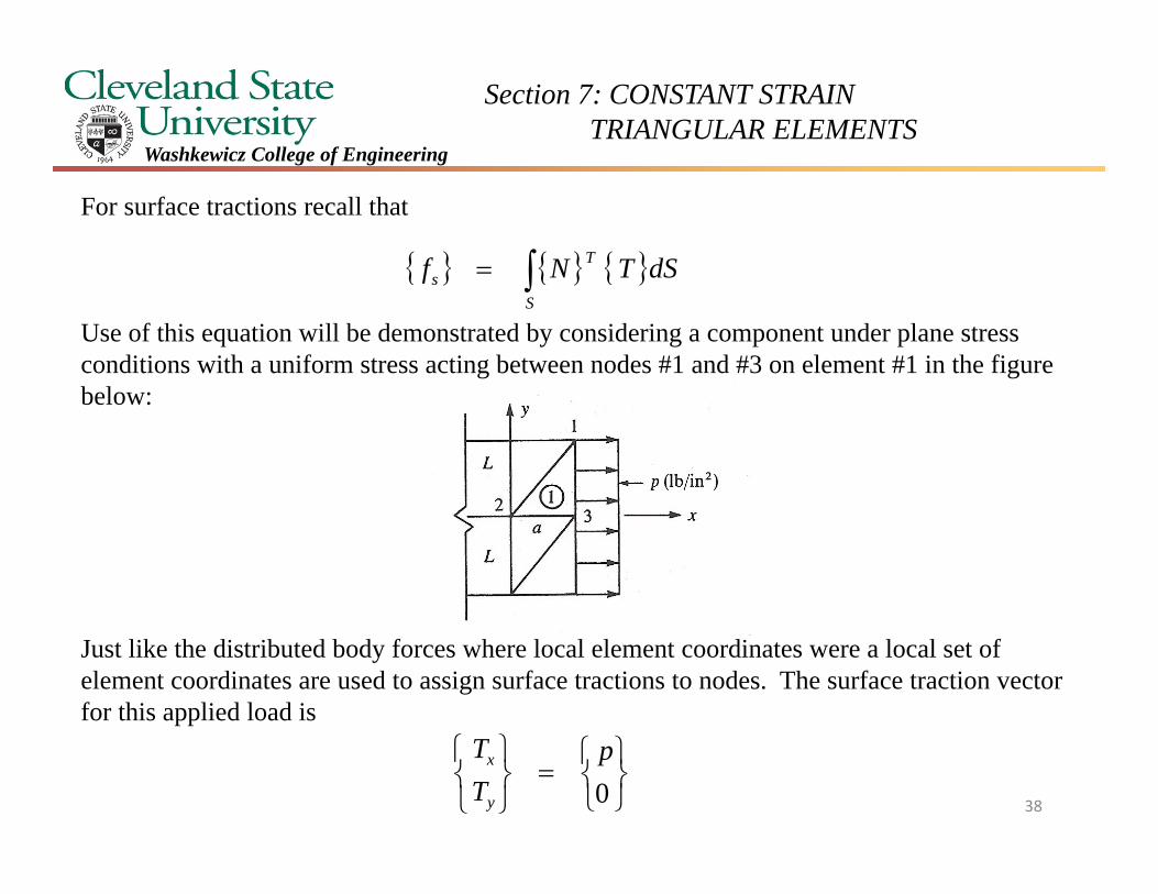
For surface tractions recall that
Use of this equation will be demonstrated by considering a component under plane stress conditions with a uniform stress acting between nodes #1 and #3 on element #1 in the figure below:
Just like the distributed body forces where local element coordinates were a local set of element coordinates are used to assign surface tractions to nodes. The surface traction vector for this applied load is
0p
TT
y
x
S
Ts dSTNf
38
Section 7: CONSTANT STRAIN TRIANGULAR ELEMENTS
Washkewicz College of Engineering
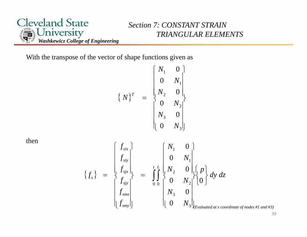
With the transpose of the vector of shape functions given as
then
3
3
2
2
1
1
00
00
00
NN
NN
NN
N T
t L
smy
smx
sjy
sjx
siy
six
s dzdyp
NN
NN
NN
ffffff
f0 0
3
3
2
2
1
1
0
00
00
00
(Evaluated at x coordinate of nodes #1 and #3)39
Section 7: CONSTANT STRAIN TRIANGULAR ELEMENTS
Washkewicz College of Engineering
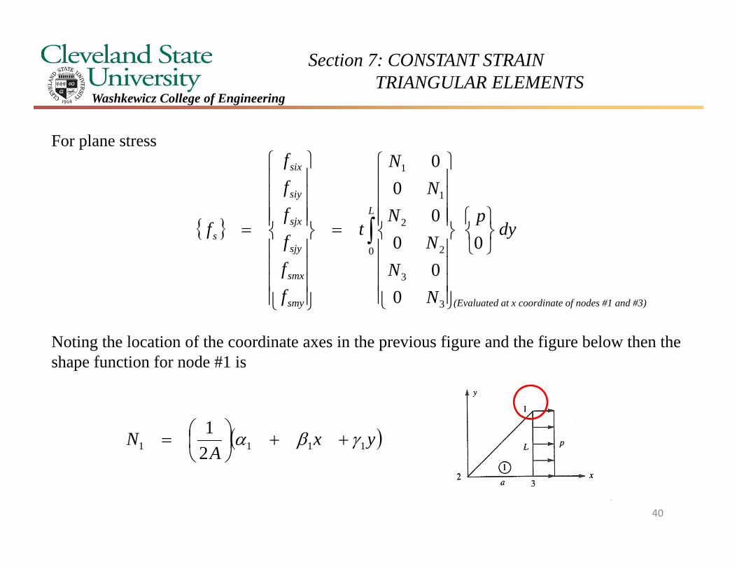
For plane stress
Noting the location of the coordinate axes in the previous figure and the figure below then the shape function for node #1 is
L
smy
smx
sjy
sjx
siy
six
s dyp
NN
NN
NN
t
ffffff
f0
3
3
2
2
1
1
0
00
00
00
yxA
N 1111 21
(Evaluated at x coordinate of nodes #1 and #3)
40
Section 7: CONSTANT STRAIN TRIANGULAR ELEMENTS
Washkewicz College of Engineering
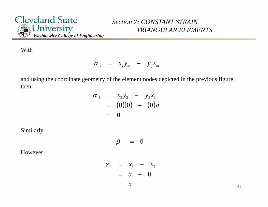
With
and using the coordinate geometry of the element nodes depicted in the previous figure, then
Similarly
However
mjmji xyyx
0
00032321
axyyx
01
aa
xx
0231
41
Section 7: CONSTANT STRAIN TRIANGULAR ELEMENTS
Washkewicz College of Engineering
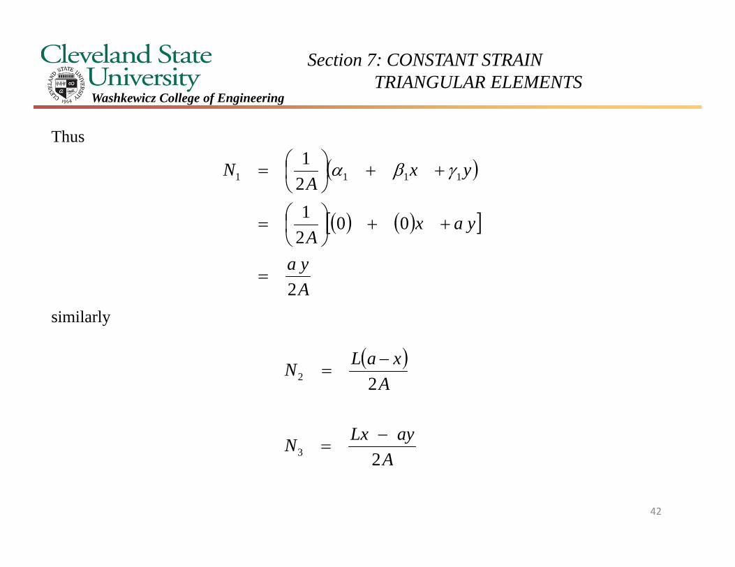
Thus
similarly
Aya
yaxA
yxA
N
2
0021
21
1111
AayLxN
AxaLN
2
2
3
2
42
Section 7: CONSTANT STRAIN TRIANGULAR ELEMENTS
Washkewicz College of Engineering
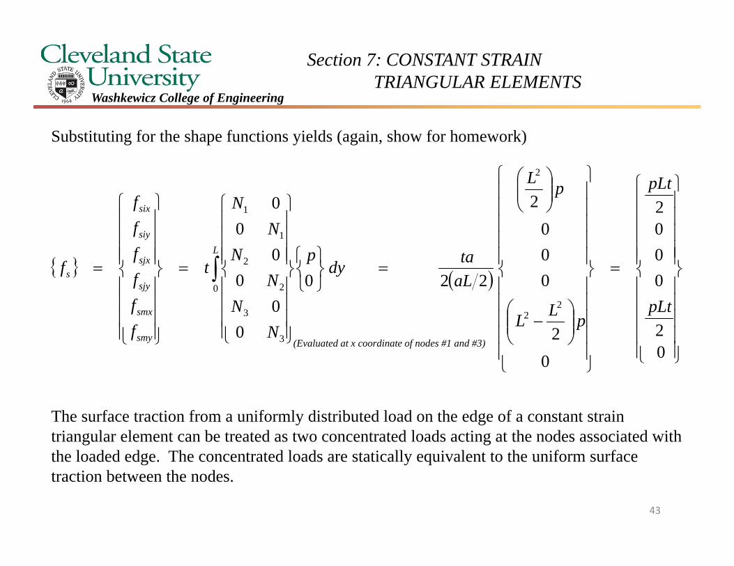
Substituting for the shape functions yields (again, show for homework)
The surface traction from a uniformly distributed load on the edge of a constant strain triangular element can be treated as two concentrated loads acting at the nodes associated with the loaded edge. The concentrated loads are statically equivalent to the uniform surface traction between the nodes.
02
0002
02
000
2
220
00
00
00
22
2
0
3
3
2
2
1
1
pLt
pLt
pLL
pL
aLtady
p
NN
NN
NN
t
ffffff
fL
smy
smx
sjy
sjx
siy
six
s
(Evaluated at x coordinate of nodes #1 and #3)
43
Section 7: CONSTANT STRAIN TRIANGULAR ELEMENTS
Washkewicz College of Engineering
In class example
44
Section 7: CONSTANT STRAIN TRIANGULAR ELEMENTS
Washkewicz College of Engineering
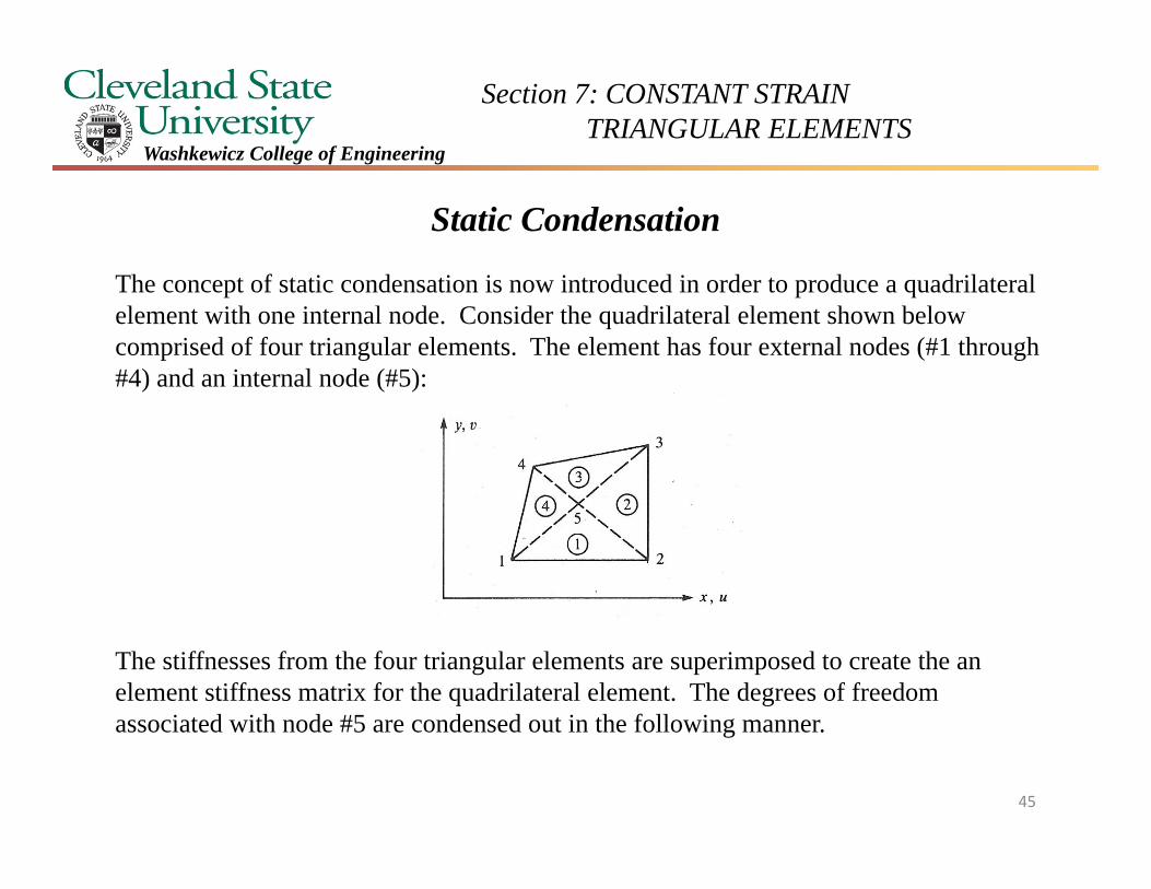
Static Condensation
The concept of static condensation is now introduced in order to produce a quadrilateral element with one internal node. Consider the quadrilateral element shown below comprised of four triangular elements. The element has four external nodes (#1 through #4) and an internal node (#5):
The stiffnesses from the four triangular elements are superimposed to create the an element stiffness matrix for the quadrilateral element. The degrees of freedom associated with node #5 are condensed out in the following manner.
45
Section 7: CONSTANT STRAIN TRIANGULAR ELEMENTS
Washkewicz College of Engineering
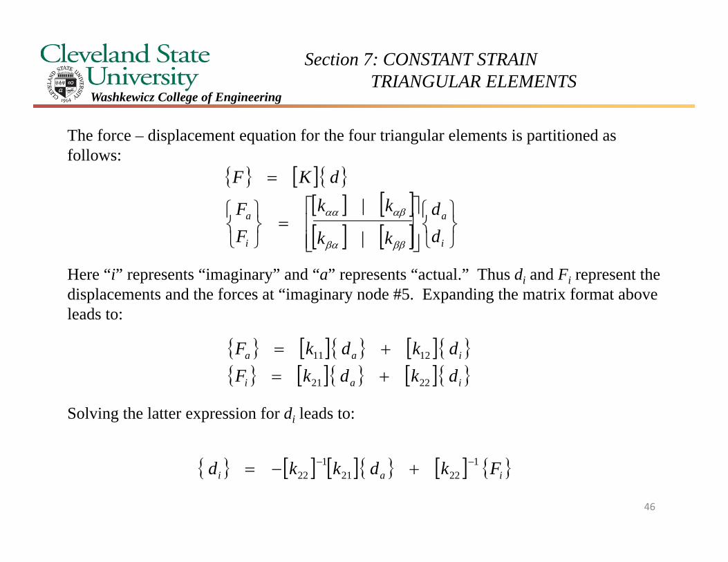
The force – displacement equation for the four triangular elements is partitioned as follows:
Here “i” represents “imaginary” and “a” represents “actual.” Thus di and Fi represent the displacements and the forces at “imaginary node #5. Expanding the matrix format above leads to:
Solving the latter expression for di leads to:
i
a
i
a
dd
kk
kk
FF
dKF
|
|
iai
iaa
dkdkFdkdkF
2221
1211
iai Fkdkkd 12221
122
46
Section 7: CONSTANT STRAIN TRIANGULAR ELEMENTS
Washkewicz College of Engineering
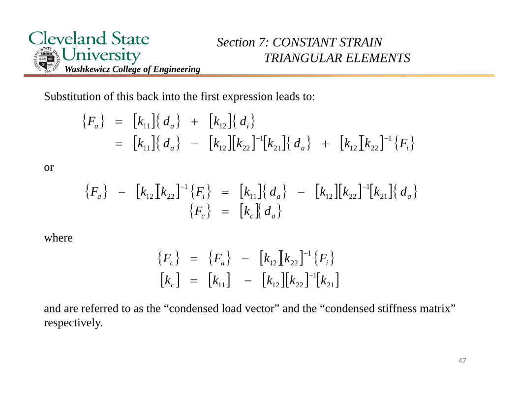
Substitution of this back into the first expression leads to:
or
where
and are referred to as the “condensed load vector” and the “condensed stiffness matrix” respectively.
iaa
iaa
Fkkdkkkdk
dkdkF1
2212211
221211
1211
acc
aaia
dkFdkkkdkFkkF
211
2212111
2212
21
1221211
12212
kkkkk
FkkFF
c
iac
47
Section 7: CONSTANT STRAIN TRIANGULAR ELEMENTS
Washkewicz College of Engineering
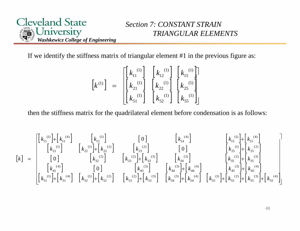
If we identify the stiffness matrix of triangular element #1 in the previous figure as:
then the stiffness matrix for the quadrilateral element before condensation is as follows:
)1(
55)1(
52)1(
51
)1(25
)1(22
)1(21
)1(15
)1(12
)1(11
)1(
kkk
kkk
kkk
k
)4(55
)3(55
)2(55
)1(55
)4(54
)3(54
)3(53
)2(53
)2(52
)1(52
)4(51
)1(51
)4(45
)3(45
)4(44
)3(44
)3(43
)4(41
)3(35
)2(35
)3(34
)3(33
)2(33
)2(32
)2(25
)1(25
)2(23
)2(22
)1(22
)1(21
)4(15
)1(15
)4(14
)1(12
)4(11
)1(11
0
0
0
0
kkkkkkkkkkkk
kkkkkk
kkkkkk
kkkkkk
kkkkkk
k
48
Section 7: CONSTANT STRAIN TRIANGULAR ELEMENTS
Washkewicz College of Engineering
)4(44
)3(44
)3(43
)4(41
)3(34
)3(33
)2(33
)2(32
)2(23
)2(22
)1(22
)1(21
)4(14
)1(12
)4(11
)1(11
0
0
0
0
kkkk
kkkk
kkkk
kkkk
kc
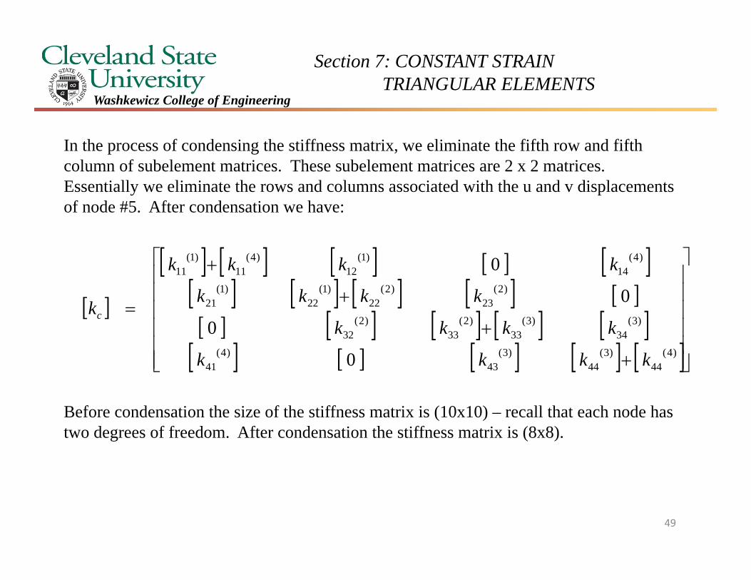
In the process of condensing the stiffness matrix, we eliminate the fifth row and fifth column of subelement matrices. These subelement matrices are 2 x 2 matrices. Essentially we eliminate the rows and columns associated with the u and v displacements of node #5. After condensation we have:
Before condensation the size of the stiffness matrix is (10x10) – recall that each node has two degrees of freedom. After condensation the stiffness matrix is (8x8).
49
Section 7: CONSTANT STRAIN TRIANGULAR ELEMENTS
Washkewicz College of Engineering
Equilibrium &Compatibility of Strains and Displacements
An approximate solution for the stress analysis of a component using finite element analysis does not produce a “perfect” distribution of stresses that an exact solution from elasticity theory would produce. One should also be cognizant that there are a limited number of exact elasticity solutions available.
The finite element method will yield approximate, but reasonable solutions. The following list describes issues associated with the fidelity of a solution obtained from a finite element analysis.
1. Equilibrium of nodal forces is satisfied. The reason for this is that the solution for displacements from the global force displacement equation
imposes equilibrium at each node. As we saw earlier structural reactions, i.e., free body diagram reaction forces, are explicitly included in the global force displacement equation above. So boundary conditions are incorporated
dKF
50
Section 7: CONSTANT STRAIN TRIANGULAR ELEMENTS
Washkewicz College of Engineering
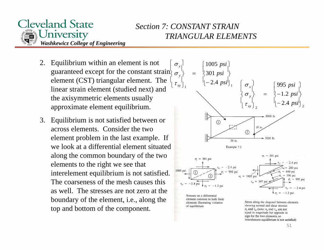
2. Equilibrium within an element is not guaranteed except for the constant strain element (CST) triangular element. The linear strain element (studied next) and the axisymmetric elements usually approximate element equilibrium.
3. Equilibrium is not satisfied between or across elements. Consider the two element problem in the last example. If we look at a differential element situated along the common boundary of the two elements to the right we see that interelement equilibrium is not satisfied. The coarseness of the mesh causes this as well. The stresses are not zero at the boundary of the element, i.e., along the top and bottom of the component.
114.2
3011005
psipsipsi
xy
y
x
224.22.1
995
psipsi
psi
xy
y
x
51
Section 7: CONSTANT STRAIN TRIANGULAR ELEMENTS
Washkewicz College of Engineering
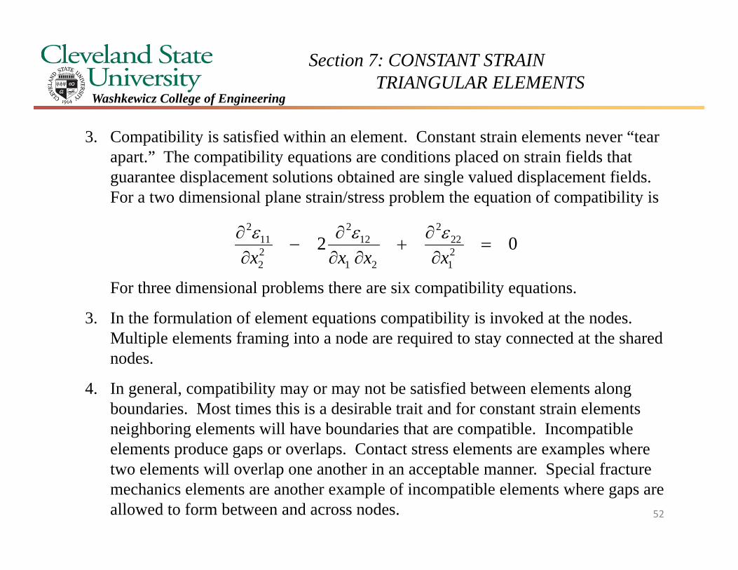
3. Compatibility is satisfied within an element. Constant strain elements never “tear apart.” The compatibility equations are conditions placed on strain fields that guarantee displacement solutions obtained are single valued displacement fields. For a two dimensional plane strain/stress problem the equation of compatibility is
For three dimensional problems there are six compatibility equations.
3. In the formulation of element equations compatibility is invoked at the nodes. Multiple elements framing into a node are required to stay connected at the shared nodes.
4. In general, compatibility may or may not be satisfied between elements along boundaries. Most times this is a desirable trait and for constant strain elements neighboring elements will have boundaries that are compatible. Incompatible elements produce gaps or overlaps. Contact stress elements are examples where two elements will overlap one another in an acceptable manner. Special fracture mechanics elements are another example of incompatible elements where gaps are allowed to form between and across nodes. 52
02 21
222
21
122
22
112
xxxx
Section 7: CONSTANT STRAIN TRIANGULAR ELEMENTS
Washkewicz College of Engineering
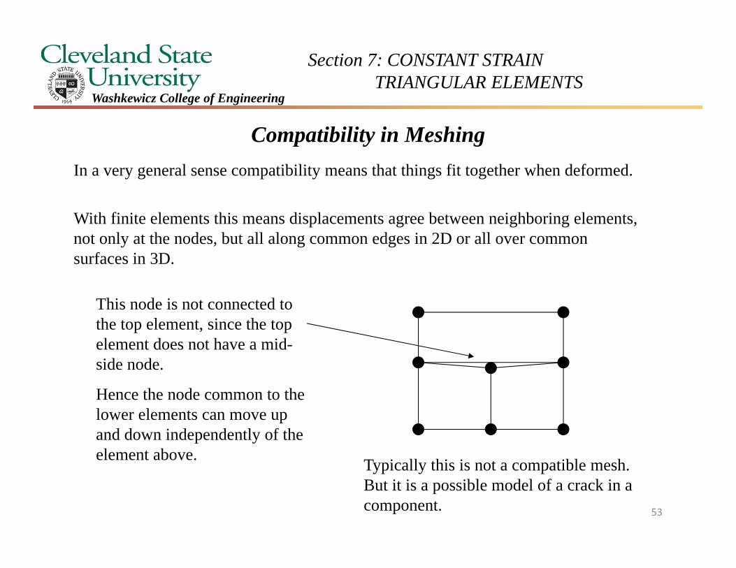
Compatibility in MeshingIn a very general sense compatibility means that things fit together when deformed.
With finite elements this means displacements agree between neighboring elements, not only at the nodes, but all along common edges in 2D or all over common surfaces in 3D.
This node is not connected to the top element, since the top element does not have a mid-side node.
Hence the node common to the lower elements can move up and down independently of the element above. Typically this is not a compatible mesh.
But it is a possible model of a crack in a component. 53
Section 7: CONSTANT STRAIN TRIANGULAR ELEMENTS
Washkewicz College of Engineering
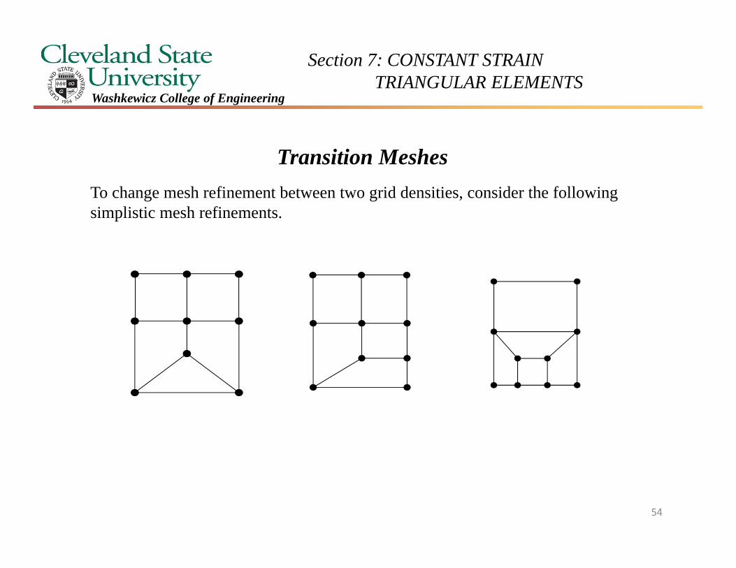
Transition MeshesTo change mesh refinement between two grid densities, consider the following simplistic mesh refinements.
54
Washkewicz College of Engineering
Section 7: CONSTANT STRAIN TRIANGULAR ELEMENTS
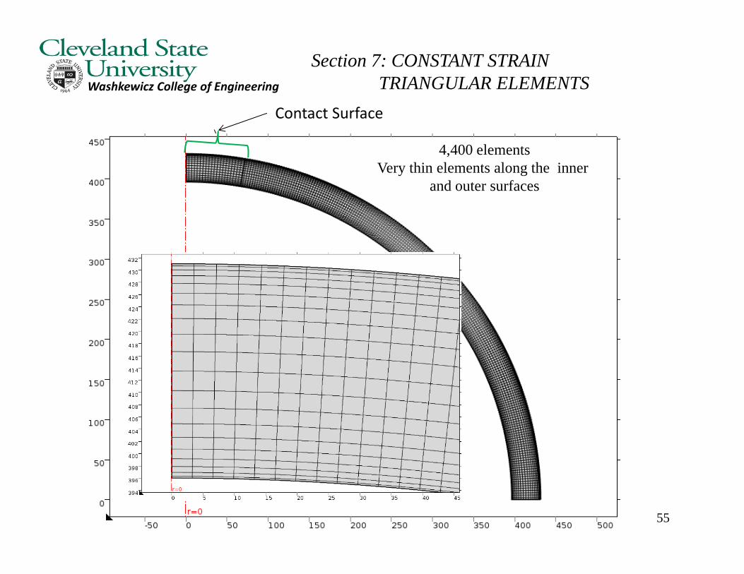
55
4,400 elementsVery thin elements along the inner
and outer surfaces
Contact Surface
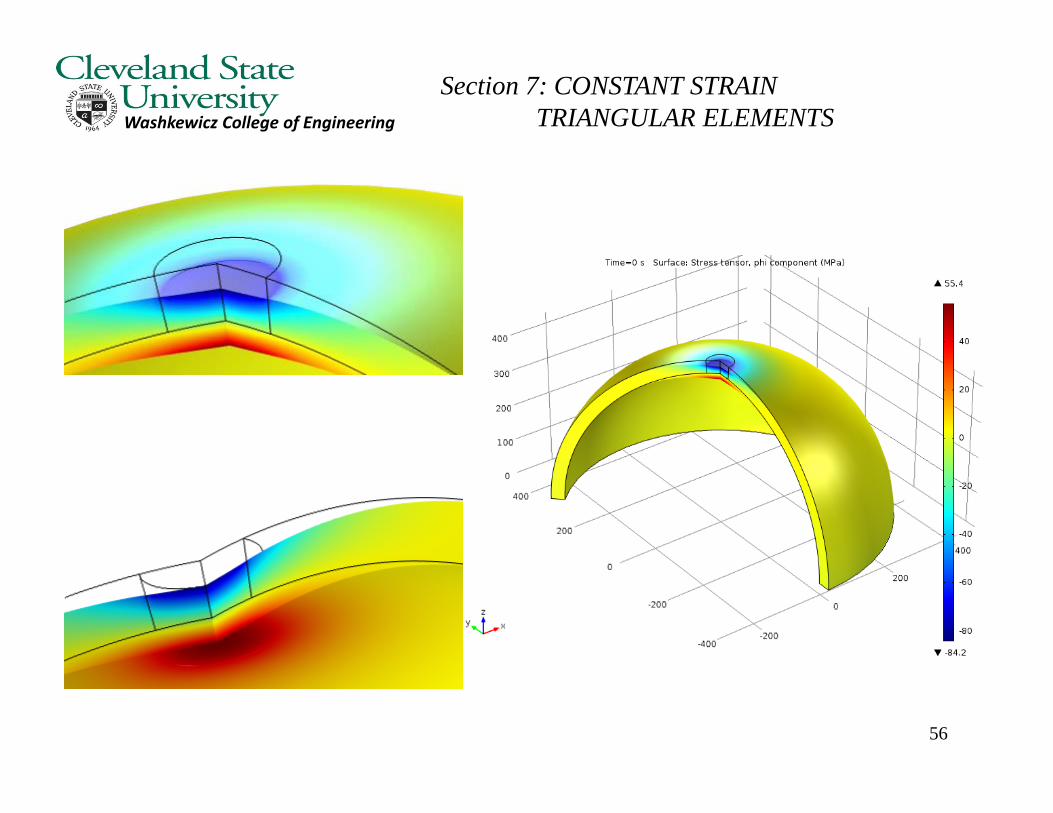
Washkewicz College of Engineering
Section 7: CONSTANT STRAIN TRIANGULAR ELEMENTS
56
Section 7: CONSTANT STRAIN TRIANGULAR ELEMENTS
Washkewicz College of Engineering
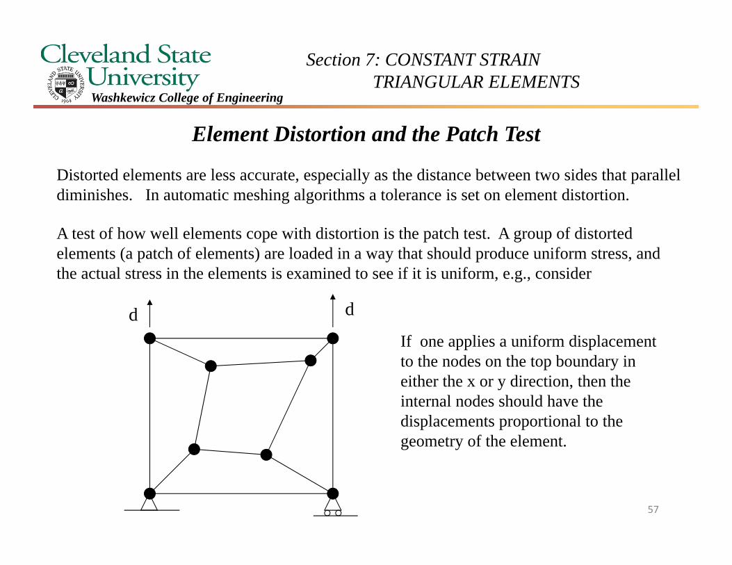
Element Distortion and the Patch Test
Distorted elements are less accurate, especially as the distance between two sides that parallel diminishes. In automatic meshing algorithms a tolerance is set on element distortion.
A test of how well elements cope with distortion is the patch test. A group of distorted elements (a patch of elements) are loaded in a way that should produce uniform stress, and the actual stress in the elements is examined to see if it is uniform, e.g., consider
ddIf one applies a uniform displacement to the nodes on the top boundary in either the x or y direction, then the internal nodes should have the displacements proportional to the geometry of the element.
57
Section 7: CONSTANT STRAIN TRIANGULAR ELEMENTS
Washkewicz College of Engineering
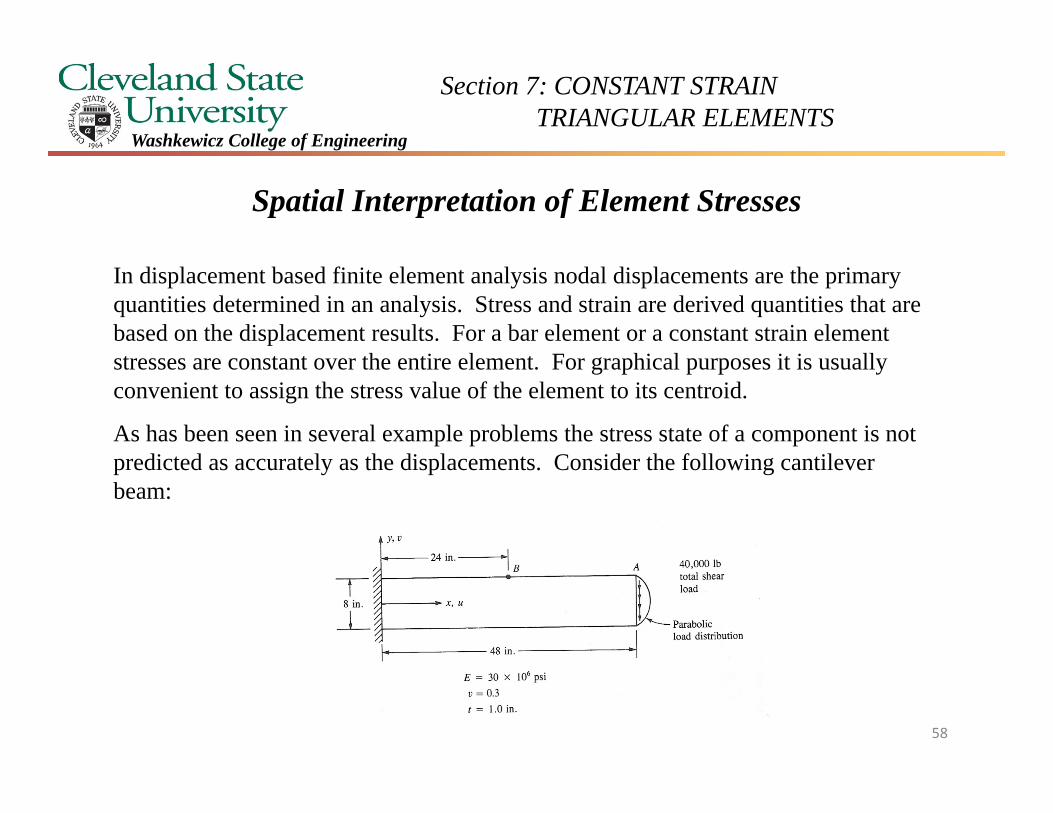
Spatial Interpretation of Element Stresses
In displacement based finite element analysis nodal displacements are the primary quantities determined in an analysis. Stress and strain are derived quantities that are based on the displacement results. For a bar element or a constant strain element stresses are constant over the entire element. For graphical purposes it is usually convenient to assign the stress value of the element to its centroid.
As has been seen in several example problems the stress state of a component is not predicted as accurately as the displacements. Consider the following cantilever beam:
58
Section 7: CONSTANT STRAIN TRIANGULAR ELEMENTS
Washkewicz College of Engineering
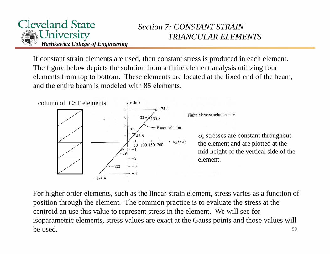
If constant strain elements are used, then constant stress is produced in each element. The figure below depicts the solution from a finite element analysis utilizing four elements from top to bottom. These elements are located at the fixed end of the beam, and the entire beam is modeled with 85 elements.
For higher order elements, such as the linear strain element, stress varies as a function of position through the element. The common practice is to evaluate the stress at the centroid an use this value to represent stress in the element. We will see for isoparametric elements, stress values are exact at the Gauss points and those values will be used.
x stresses are constant throughout the element and are plotted at the mid height of the vertical side of the element.
column of CST elements
59
Section 7: CONSTANT STRAIN TRIANGULAR ELEMENTS
Washkewicz College of Engineering
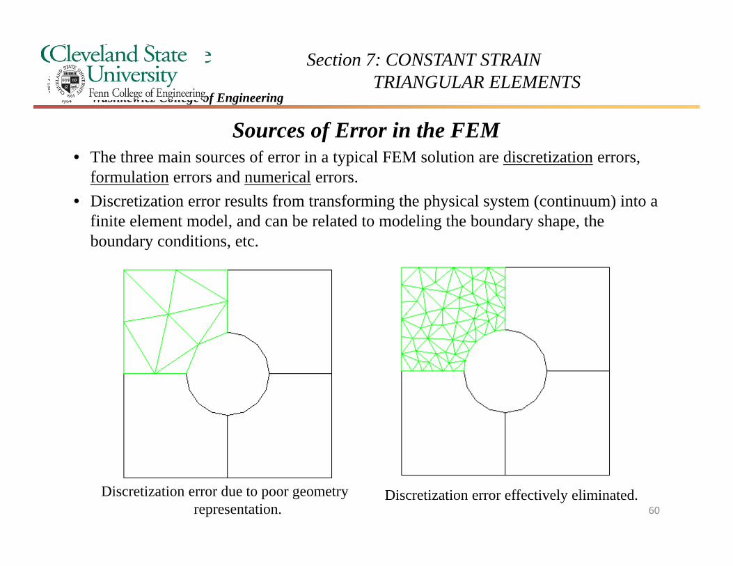
Sources of Error in the FEM• The three main sources of error in a typical FEM solution are discretization errors,
formulation errors and numerical errors.• Discretization error results from transforming the physical system (continuum) into a
finite element model, and can be related to modeling the boundary shape, the boundary conditions, etc.
Discretization error due to poor geometryrepresentation.
Discretization error effectively eliminated.60
Section 7: CONSTANT STRAIN TRIANGULAR ELEMENTS
Washkewicz College of Engineering
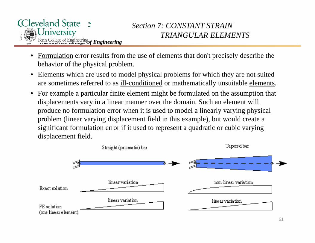
• Formulation error results from the use of elements that don't precisely describe the behavior of the physical problem.
• Elements which are used to model physical problems for which they are not suited are sometimes referred to as ill-conditioned or mathematically unsuitable elements.
• For example a particular finite element might be formulated on the assumption that displacements vary in a linear manner over the domain. Such an element will produce no formulation error when it is used to model a linearly varying physical problem (linear varying displacement field in this example), but would create a significant formulation error if it used to represent a quadratic or cubic varying displacement field.
61
Section 7: CONSTANT STRAIN TRIANGULAR ELEMENTS
Washkewicz College of Engineering
• Numerical error occurs as a result of numerical calculation procedures, and includes truncation errors and round off errors.
• Numerical error is therefore a problem mainly concerning the FEM vendors and developers.
• The user can also contribute to the numerical accuracy, for example, by specifying a physical quantity, say Young’s modulus, E, to an inadequate number of decimal places.
62

Section 7: CONSTANT STRAIN TRIANGULAR ELEMENTS
Washkewicz College of Engineering
Basic Scorecard – CST Element
yxA
N
yxA
N
yxA
N
mmmm
jjjj
iiii
21
21
21
ijmmijjmi
jimimjmji
jijimmimijmjmji
xxxxxx
yyyyyy
xyyxyxxyxyyx
jimimjmji yyxyyxyyxA 2
63
Section 7: CONSTANT STRAIN TRIANGULAR ELEMENTS
Washkewicz College of Engineering
Basic Scorecard – CST Element
yxA
N
yxA
N
yxA
N
mmmm
jjjj
iiii
21
21
21
ijmmijjmi
jimimjmji
jijimmimijmjmji
xxxxxx
yyyyyy
xyyxyxxyxyyx
jimimjmji yyxyyxyyxA 2
64
Section 7: CONSTANT STRAIN TRIANGULAR ELEMENTS
Washkewicz College of Engineering
A
yxAxx
N
Ayx
AxxN
Ayx
AxxN
mmmm
m
jjjj
j
iiii
i
221
221
221
mmjjii
mji
mji
AB
000
000
21
A
yxAyy
N
Ayx
AyyN
Ayx
AyyN
mmmm
m
jjjj
j
iiii
i
221
221
221
65
Section 7: CONSTANT STRAIN TRIANGULAR ELEMENTS
Washkewicz College of Engineering
FKddKF 1
N
e
ekK1
mmmjmi
jmjjji
imijii
TT
kkk
kkk
kkk
AtBDBk
m
m
j
j
i
i
mmjjii
mji
mji
xy
y
x
vu
v
uvu
A
000
000
21
66
Section 7: CONSTANT STRAIN TRIANGULAR ELEMENTS
Washkewicz College of Engineering
xy
y
x
xy
x
x
D
2100
01
01
1 2
ED
22100
010
01
211
ED
67