section 233300 - air duct accessories
TRANSCRIPT
Copyright 2013 AIA MasterSpec Premium 03/13PRODUCT MASTERSPEC LICENSED BY ARCOM TO CL WARD & FAMILY INC.
Copyright 2013 by The American Institute of Architects (AIA)
Exclusively published and distributed by Architectural Computer Services, Inc. (ARCOM) for the AIA
This Product MasterSpec Section is licensed by ARCOM to CL Ward & Family Inc, ("Licensee").
This Product MasterSpec Section modifies the original MasterSpec text, and does not include the full content of the original MasterSpec Section.
Revisions made to the original MasterSpec text are made solely by the Licensee and are not endorsed by, or representative of the opinions of, ARCOM or The American Institute of Architects (AIA). Neither AIA nor ARCOM are liable in any way for such revisions or for the use of this Product MasterSpec Section by any end user. A qualified design professional should review and edit the document to suit project requirements.
For more information, contact CL Ward & Family Inc., 1100 Ashwood Drive, Suite 1102, Canonsburg, PA 15317; Phone: (724) 743-5903; Fax: (724) 743-5904; Website: www.clward.com ; Email: [email protected].
For information about MasterSpec contact ARCOM at (800) 424-5080 or visit www.MasterSpec.com.
SECTION 233300 - AIR DUCT ACCESSORIES
TIPS:
To view non-printing Editor's Notes that provide guidance for editing, click on Masterworks/Single-File Formatting/Toggle/Editor's Notes.
To read detailed research, technical information about products and materials, and coordination checklists, click on Masterworks/Supporting Information.
Revise this Section by deleting and inserting text to meet Project-specific requirements.
This Section uses the term "Architect." Change this term to match that used to identify the design professional as defined in the General and Supplementary Conditions.
Verify that Section titles referenced in this Section are correct for this Project's Specifications; Section titles may have changed.
PART 1 - GENERAL
1.1 RELATED DOCUMENTS
Retain or delete this article in all Sections of Project Manual.
A. Drawings and general provisions of the Contract, including General and Supplementary Conditions and Division 01 Specification Sections, apply to this Section.
AIR DUCT ACCESSORIES 233300 - 1
Copyright 2013 AIA MasterSpec Premium 03/13PRODUCT MASTERSPEC LICENSED BY ARCOM TO CL WARD & FAMILY INC.
1.2 SUMMARY
A. Section Includes:
1. Backdraft and pressure relief dampers.2. Barometric relief dampers.3. Manual volume dampers.4. Control dampers.5. Fire dampers.6. Ceiling radiation dampers.7. Smoke dampers.8. Combination fire and smoke dampers.9. Corridor dampers.10. Flange connectors.11. Duct silencers.12. Turning vanes.13. Remote damper operators.14. Duct-mounted access doors.15. Flexible connectors.16. Flexible ducts.17. Duct security bars.18. Duct accessory hardware.
B. Related Requirements:
Retain subparagraphs below to cross-reference requirements Contractor might expect to find in this Section but are specified in other Sections.
1. Section 233723 "HVAC Gravity Ventilators" for roof-mounted ventilator caps.
Retain one of two subparagraphs below.2. Section 283111 "Digital, Addressable Fire-Alarm System" for duct-mounted fire and
smoke detectors.3. Section 283112 "Zoned (DC-Loop) Fire-Alarm System" for duct-mounted fire and smoke
detectors.
1.3 ACTION SUBMITTALS
A. Product Data: For each type of product.
1. For duct silencers, include pressure drop and dynamic insertion loss data. Include breakout noise calculations for high transmission loss casings.
B. LEED Submittals:
1. Product Data for Prerequisite IEQ 1: Documentation indicating that units comply with ASHRAE 62.1, Section 5 - "Systems and Equipment."
2. Product Data for Prerequisite EA 2: Documentation indicating that duct insulation R-values comply with tables in ASHRAE/IESNA 90.1, Section 6 - "Heating, Ventilating, and Air Conditioning."
AIR DUCT ACCESSORIES 233300 - 2
Copyright 2013 AIA MasterSpec Premium 03/13PRODUCT MASTERSPEC LICENSED BY ARCOM TO CL WARD & FAMILY INC.
C. Shop Drawings: For duct accessories. Include plans, elevations, sections, details and attachments to other work.
1. Detail duct accessories fabrication and installation in ducts and other construction. Include dimensions, weights, loads, and required clearances; and method of field assembly into duct systems and other construction. Include the following:
a. Special fittings.b. Manual volume damper installations.c. Control-damper installations.d. Fire-damper, smoke-damper, combination fire- and smoke-damper, ceiling, and
corridor damper installations, including sleeves; and duct-mounted access doors and remote damper operators.
e. Duct security bars.
Retain "Wiring Diagrams" Subparagraph below if equipment includes wiring.f. Wiring Diagrams: For power, signal, and control wiring.
1.4 INFORMATIONAL SUBMITTALS
Retain "Coordination Drawings" Paragraph below for situations where limited space necessitates maximum utilization for efficient installation of different components or if coordination is required for installation of products and materials by separate installers. Preparation of coordination drawings requires the participation of each trade involved in installations within the limited space.
A. Coordination Drawings: Reflected ceiling plans, drawn to scale, on which ceiling-mounted access panels and access doors required for access to duct accessories are shown and coordinated with each other, using input from Installers of the items involved.
Retain "Source quality-control reports" Paragraph below if retaining "Source Quality Control" Paragraph in "Duct Silencers" Article.
B. Source quality-control reports.
1.5 CLOSEOUT SUBMITTALS
A. Operation and Maintenance Data: For air duct accessories to include in operation and maintenance manuals.
1.6 MAINTENANCE MATERIAL SUBMITTALS
A. Furnish extra materials that match products installed and that are packaged with protective covering for storage and identified with labels describing contents.
1. Fusible Links: Furnish quantity equal to [10] <Insert number> percent of amount installed.
AIR DUCT ACCESSORIES 233300 - 3
Copyright 2013 AIA MasterSpec Premium 03/13PRODUCT MASTERSPEC LICENSED BY ARCOM TO CL WARD & FAMILY INC.
PART 2 - PRODUCTS
See Editing Instruction No. 1 in the Evaluations for cautions about named manufacturers and products. For an explanation of options and Contractor's product selection procedures, see Section 016000 "Product Requirements."
2.1 ASSEMBLY DESCRIPTION
A. Comply with NFPA 90A, "Installation of Air Conditioning and Ventilating Systems," and with NFPA 90B, "Installation of Warm Air Heating and Air Conditioning Systems."
B. Comply with SMACNA's "HVAC Duct Construction Standards - Metal and Flexible" for acceptable materials, material thicknesses, and duct construction methods unless otherwise indicated. Sheet metal materials shall be free of pitting, seam marks, roller marks, stains, discolorations, and other imperfections.
2.2 MATERIALS
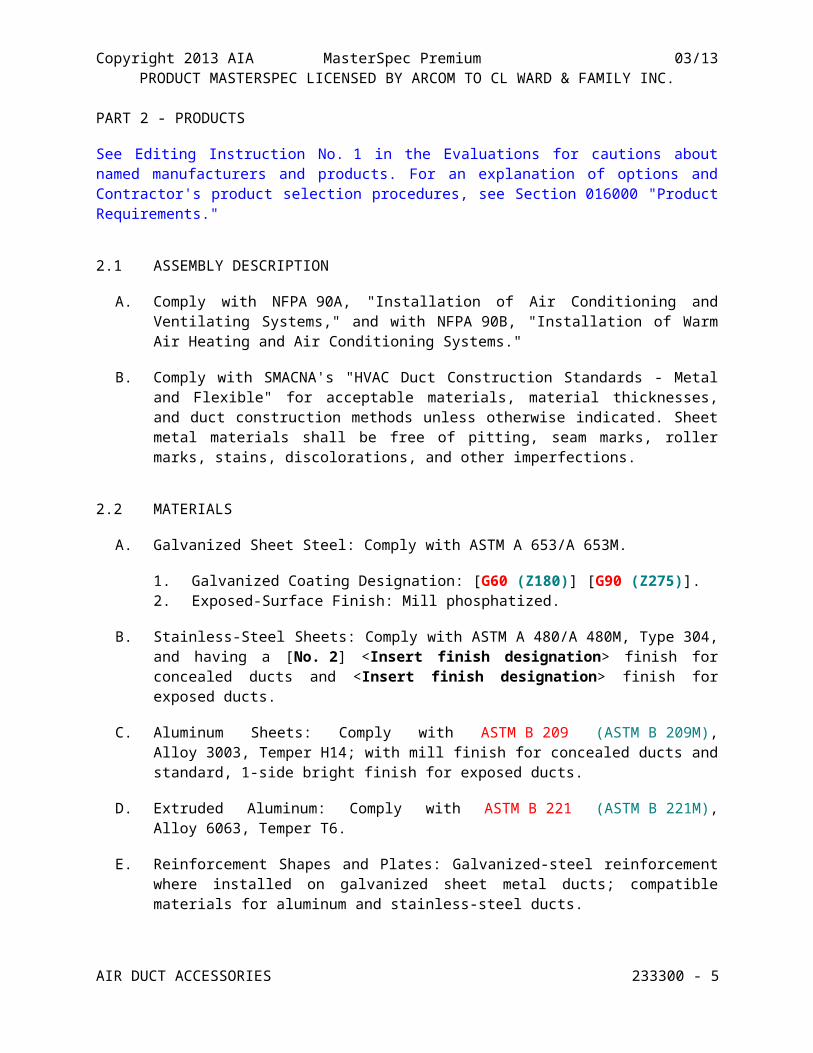
A. Galvanized Sheet Steel: Comply with ASTM A 653/A 653M.
1. Galvanized Coating Designation: [G60 (Z180)] [G90 (Z275)].2. Exposed-Surface Finish: Mill phosphatized.
B. Stainless-Steel Sheets: Comply with ASTM A 480/A 480M, Type 304, and having a [No. 2] <Insert finish designation> finish for concealed ducts and <Insert finish designation> finish for exposed ducts.
C. Aluminum Sheets: Comply with ASTM B 209 (ASTM B 209M), Alloy 3003, Temper H14; with mill finish for concealed ducts and standard, 1-side bright finish for exposed ducts.
D. Extruded Aluminum: Comply with ASTM B 221 (ASTM B 221M), Alloy 6063, Temper T6.
E. Reinforcement Shapes and Plates: Galvanized-steel reinforcement where installed on galvanized sheet metal ducts; compatible materials for aluminum and stainless-steel ducts.
F. Tie Rods: Galvanized steel, 1/4-inch (6-mm) minimum diameter for lengths 36 inches (900 mm) or less; 3/8-inch (10-mm) minimum diameter for lengths longer than 36 inches (900 mm).
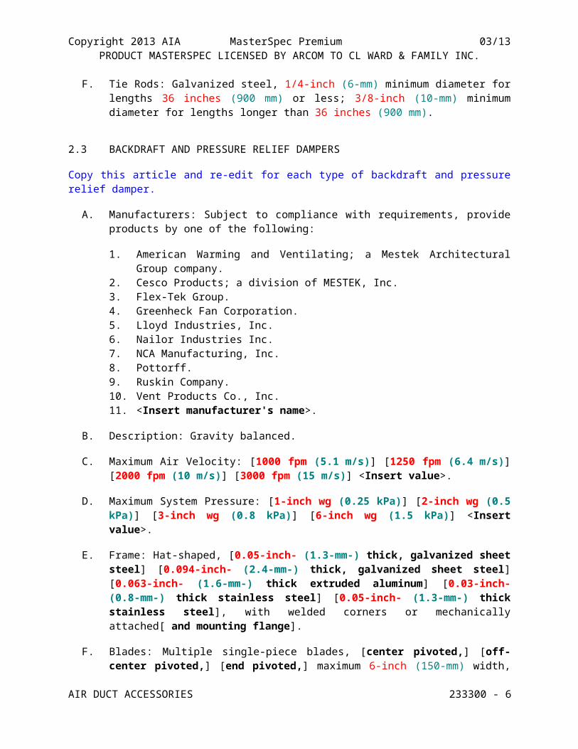
2.3 BACKDRAFT AND PRESSURE RELIEF DAMPERS
Copy this article and re-edit for each type of backdraft and pressure relief damper.
A. Manufacturers: Subject to compliance with requirements, provide products by one of the following:
1. American Warming and Ventilating; a Mestek Architectural Group company.2. Cesco Products; a division of MESTEK, Inc.3. Flex-Tek Group.4. Greenheck Fan Corporation.
AIR DUCT ACCESSORIES 233300 - 4
Copyright 2013 AIA MasterSpec Premium 03/13PRODUCT MASTERSPEC LICENSED BY ARCOM TO CL WARD & FAMILY INC.
5. Lloyd Industries, Inc.6. Nailor Industries Inc.7. NCA Manufacturing, Inc.8. Pottorff.9. Ruskin Company.10. Vent Products Co., Inc.11. <Insert manufacturer's name>.
B. Description: Gravity balanced.
C. Maximum Air Velocity: [1000 fpm (5.1 m/s)] [1250 fpm (6.4 m/s)] [2000 fpm (10 m/s)] [3000 fpm (15 m/s)] <Insert value>.
D. Maximum System Pressure: [1-inch wg (0.25 kPa)] [2-inch wg (0.5 kPa)] [3-inch wg (0.8 kPa)] [6-inch wg (1.5 kPa)] <Insert value>.
E. Frame: Hat-shaped, [0.05-inch- (1.3-mm-) thick, galvanized sheet steel] [0.094-inch- (2.4-mm-) thick, galvanized sheet steel] [0.063-inch- (1.6-mm-) thick extruded aluminum] [0.03-inch- (0.8-mm-) thick stainless steel] [0.05-inch- (1.3-mm-) thick stainless steel], with welded corners or mechanically attached[ and mounting flange].
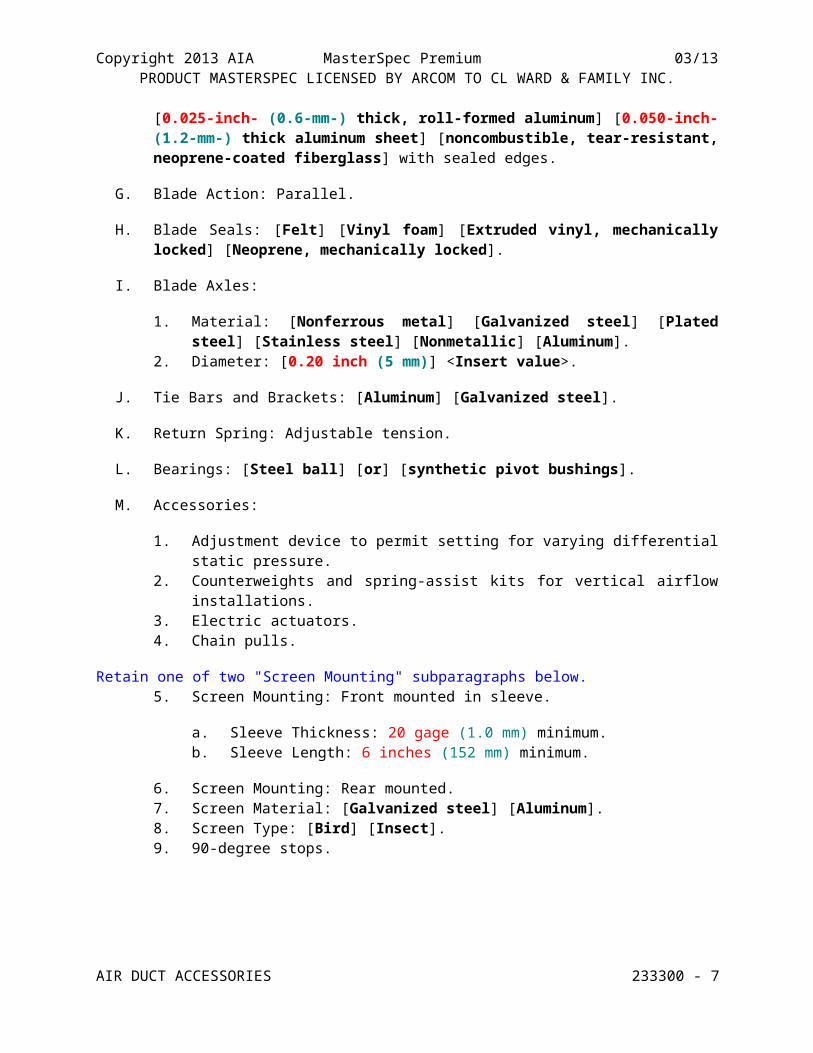
F. Blades: Multiple single-piece blades, [center pivoted,] [off-center pivoted,] [end pivoted,] maximum 6-inch (150-mm) width, [0.025-inch- (0.6-mm-) thick, roll-formed aluminum] [0.050-inch- (1.2-mm-) thick aluminum sheet] [noncombustible, tear-resistant, neoprene-coated fiberglass] with sealed edges.
G. Blade Action: Parallel.
H. Blade Seals: [Felt] [Vinyl foam] [Extruded vinyl, mechanically locked] [Neoprene, mechanically locked].
I. Blade Axles:
1. Material: [Nonferrous metal] [Galvanized steel] [Plated steel] [Stainless steel] [Nonmetallic] [Aluminum].
2. Diameter: [0.20 inch (5 mm)] <Insert value>.
J. Tie Bars and Brackets: [Aluminum] [Galvanized steel].
K. Return Spring: Adjustable tension.
L. Bearings: [Steel ball] [or] [synthetic pivot bushings].
M. Accessories:
1. Adjustment device to permit setting for varying differential static pressure.2. Counterweights and spring-assist kits for vertical airflow installations.3. Electric actuators.4. Chain pulls.
Retain one of two "Screen Mounting" subparagraphs below.
AIR DUCT ACCESSORIES 233300 - 5
Copyright 2013 AIA MasterSpec Premium 03/13PRODUCT MASTERSPEC LICENSED BY ARCOM TO CL WARD & FAMILY INC.
5. Screen Mounting: Front mounted in sleeve.
a. Sleeve Thickness: 20 gage (1.0 mm) minimum.b. Sleeve Length: 6 inches (152 mm) minimum.
6. Screen Mounting: Rear mounted.7. Screen Material: [Galvanized steel] [Aluminum].8. Screen Type: [Bird] [Insect].9. 90-degree stops.
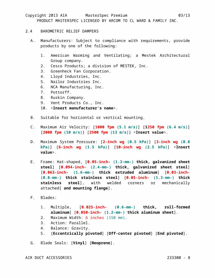
2.4 BAROMETRIC RELIEF DAMPERS
A. Manufacturers: Subject to compliance with requirements, provide products by one of the following:
1. American Warming and Ventilating; a Mestek Architectural Group company.2. Cesco Products; a division of MESTEK, Inc.3. Greenheck Fan Corporation.4. Lloyd Industries, Inc.5. Nailor Industries Inc.6. NCA Manufacturing, Inc.7. Pottorff.8. Ruskin Company.9. Vent Products Co., Inc.10. <Insert manufacturer's name>.
B. Suitable for horizontal or vertical mounting.
C. Maximum Air Velocity: [1000 fpm (5.1 m/s)] [1250 fpm (6.4 m/s)] [2000 fpm (10 m/s)] [2500 fpm (13 m/s)] <Insert value>.
D. Maximum System Pressure: [2-inch wg (0.5 kPa)] [3-inch wg (0.8 kPa)] [6-inch wg (1.5 kPa)] [10-inch wg (2.5 kPa)] <Insert value>.
E. Frame: Hat-shaped, [0.05-inch- (1.3-mm-) thick, galvanized sheet steel] [0.094-inch- (2.4-mm-) thick, galvanized sheet steel] [0.063-inch- (1.6-mm-) thick extruded aluminum] [0.03-inch- (0.8-mm-) thick stainless steel] [0.05-inch- (1.3-mm-) thick stainless steel], with welded corners or mechanically attached[ and mounting flange].
F. Blades:
1. Multiple, [0.025-inch- (0.6-mm-) thick, roll-formed aluminum] [0.050-inch- (1.2-mm-) thick aluminum sheet].
2. Maximum Width: 6 inches (150 mm).3. Action: Parallel.4. Balance: Gravity.5. [Eccentrically pivoted] [Off-center pivoted] [End pivoted].
G. Blade Seals: [Vinyl] [Neoprene].
AIR DUCT ACCESSORIES 233300 - 6
Copyright 2013 AIA MasterSpec Premium 03/13PRODUCT MASTERSPEC LICENSED BY ARCOM TO CL WARD & FAMILY INC.
H. Blade Axles: [Galvanized steel] [Nonferrous metal] [Plated steel] [Stainless steel] [Nonmetallic].
I. Tie Bars and Brackets:
1. Material: [Aluminum] [Galvanized steel].2. Rattle free with 90-degree stop.
J. Return Spring: Adjustable tension.
K. Bearings: [Synthetic] [Stainless steel] [Bronze].
L. Accessories:
1. Flange on intake.2. Adjustment device to permit setting for varying differential static pressures.3. <Insert accessories>.
2.5 MANUAL VOLUME DAMPERS
Show dampers on Drawings. If both standard and low-leakage volume dampers are required, identify each damper type on Drawings.
A. Standard, Steel, Manual Volume Dampers:
1. Manufacturers: Subject to compliance with requirements, provide products by one of the following:
a. Aire Technologies.b. American Warming and Ventilating; a Mestek Architectural Group company.c. Flexmaster U.S.A., Inc.d. Flex-Tek Group.e. McGill AirFlow LLC.f. Nailor Industries Inc.g. Pottorff.h. Ruskin Company.i. Trox USA Inc.j. Vent Products Co., Inc.k. <Insert manufacturer's name>.
2. Standard leakage rating[, with linkage outside airstream].3. Suitable for horizontal or vertical applications.4. Frames:
a. Frame: Hat-shaped, [0.094-inch- (2.4-mm-) thick, galvanized sheet steel] [0.05-inch- (1.3-mm-) thick stainless steel].
b. Mitered and welded corners.c. Flanges for attaching to walls and flangeless frames for installing in ducts.
5. Blades:
AIR DUCT ACCESSORIES 233300 - 7
Copyright 2013 AIA MasterSpec Premium 03/13PRODUCT MASTERSPEC LICENSED BY ARCOM TO CL WARD & FAMILY INC.
a. Multiple or single blade.b. Parallel- or opposed-blade design.c. Stiffen damper blades for stability.d. [Galvanized] [Stainless]-steel, 0.064 inch (1.62 mm) thick.
6. Blade Axles: [Galvanized steel] [Stainless steel] [Nonferrous metal].7. Bearings:
a. [Oil-impregnated bronze] [Molded synthetic] [Oil-impregnated stainless-steel sleeve] [Stainless-steel sleeve].
b. Dampers in ducts with pressure classes of 3-inch wg (750 Pa) or less shall have axles full length of damper blades and bearings at both ends of operating shaft.
8. Tie Bars and Brackets: Galvanized steel.
Retain "Standard, Aluminum, Manual Volume Dampers" Paragraph below for aluminum ducts. Coordinate with "Installation" Article and Section 233113 "Metal Ducts."
B. Standard, Aluminum, Manual Volume Dampers:
1. Manufacturers: Subject to compliance with requirements, provide products by one of the following:
a. American Warming and Ventilating; a Mestek Architectural Group company.b. McGill AirFlow LLC.c. Nailor Industries Inc.d. Pottorff.e. Ruskin Company.f. Trox USA Inc.g. Vent Products Co., Inc.h. <Insert manufacturer's name>.
2. Standard leakage rating[, with linkage outside airstream].3. Suitable for horizontal or vertical applications.4. Frames: Hat-shaped, 0.10-inch- (2.5-mm-) thick, aluminum sheet channels; frames with
flanges for attaching to walls and flangeless frames for installing in ducts.5. Blades:
a. Multiple or single blade.b. Parallel- or opposed-blade design.c. Stiffen damper blades for stability.
Retain "Roll-Formed Aluminum Blades" or "Extruded-Aluminum Blades" Subparagraph below.d. Roll-Formed Aluminum Blades: 0.10-inch- (2.5-mm-) thick aluminum sheet.e. Extruded-Aluminum Blades: 0.050-inch- (1.2-mm-) thick extruded aluminum.
6. Blade Axles: [Galvanized steel] [Stainless steel] [Nonferrous metal].7. Bearings:
a. [Oil-impregnated bronze] [Molded synthetic] [Stainless-steel sleeve].
AIR DUCT ACCESSORIES 233300 - 8
Copyright 2013 AIA MasterSpec Premium 03/13PRODUCT MASTERSPEC LICENSED BY ARCOM TO CL WARD & FAMILY INC.
b. Dampers in ducts with pressure classes of 3-inch wg (750 Pa) or less shall have axles full length of damper blades and bearings at both ends of operating shaft.
8. Tie Bars and Brackets: Aluminum.
C. Low-Leakage, Steel, Manual Volume Dampers:
1. Manufacturers: Subject to compliance with requirements, provide products by one of the following:
a. American Warming and Ventilating; a Mestek Architectural Group company.b. Flex-Tek Group.c. McGill AirFlow LLC.d. Nailor Industries Inc.e. Pottorff.f. Ruskin Company.g. Trox USA Inc.h. Vent Products Co., Inc.i. <Insert manufacturer's name>.
2. Comply with AMCA 500-D testing for damper rating.
Manufacturers having products tested in AMCA-accredited laboratories, with test results verified by AMCA staff, and having obtained the proper license from AMCA, can offer products bearing AMCA's Certified Ratings Seal for air performance or air leakage, or both. Verify availability with manufacturers retained in list above.
3. Low-leakage rating[, with linkage outside airstream,] and bearing AMCA's Certified Ratings Seal for both air performance and air leakage.
4. Suitable for horizontal or vertical applications.5. Frames:
a. [Hat] [U] [Angle] shaped.b. [0.094-inch- (2.4-mm-) thick, galvanized sheet steel] [0.05-inch- (1.3-mm-)
thick stainless steel].c. Mitered and welded corners.d. Flanges for attaching to walls and flangeless frames for installing in ducts.
6. Blades:
a. Multiple or single blade.b. Parallel- or opposed-blade design.c. Stiffen damper blades for stability.d. [Galvanized] [Stainless], roll-formed steel, 0.064 inch (1.62 mm) thick.
7. Blade Axles: [Galvanized steel] [Stainless steel] [Nonferrous metal].8. Bearings:
a. [Oil-impregnated bronze] [Molded synthetic] [Oil-impregnated stainless-steel sleeve] [Stainless-steel sleeve].
b. Dampers in ducts with pressure classes of 3-inch wg (750 Pa) or less shall have axles full length of damper blades and bearings at both ends of operating shaft.
AIR DUCT ACCESSORIES 233300 - 9
Copyright 2013 AIA MasterSpec Premium 03/13PRODUCT MASTERSPEC LICENSED BY ARCOM TO CL WARD & FAMILY INC.
9. Blade Seals: [Felt] [Vinyl] [Neoprene].10. Jamb Seals: Cambered [stainless steel] [aluminum].11. Tie Bars and Brackets: [Galvanized steel] [Aluminum].12. Accessories:
a. Include locking device to hold single-blade dampers in a fixed position without vibration.
Retain "Low-Leakage, Aluminum, Manual Volume Dampers" Paragraph below for aluminum ducts. Coordinate with "Installation" Article and Section 233113 "Metal Ducts."
D. Low-Leakage, Aluminum, Manual Volume Dampers:
1. Manufacturers: Subject to compliance with requirements, provide products by one of the following:
a. American Warming and Ventilating; a Mestek Architectural Group company.b. McGill AirFlow LLC.c. Nailor Industries Inc.d. Pottorff.e. Ruskin Company.f. Trox USA Inc.g. Vent Products Co., Inc.h. <Insert manufacturer's name>.
2. Comply with AMCA 500-D testing for damper rating.
Manufacturers having products tested in AMCA-accredited laboratories, with test results verified by AMCA staff, and having obtained the proper license from AMCA, can offer products bearing AMCA's Certified Ratings Seal for air performance or air leakage, or both. Verify availability with manufacturers retained in list above.
3. Low-leakage rating[, with linkage outside airstream,] and bearing AMCA's Certified Ratings Seal for both air performance and air leakage.
4. Suitable for horizontal or vertical applications.5. Frames: [Hat] [U] [Angle]-shaped, 0.10-inch- (2.5-mm-) thick, aluminum sheet
channels; frames with flanges for attaching to walls and flangeless frames for installing in ducts.
6. Blades:
a. Multiple or single blade.b. Parallel- or opposed-blade design.
Retain "Roll-Formed Aluminum Blades" or "Extruded-Aluminum Blades" Subparagraph below.c. Roll-Formed Aluminum Blades: 0.10-inch- (2.5-mm-) thick aluminum sheet.d. Extruded-Aluminum Blades: 0.050-inch- (1.2-mm-) thick extruded aluminum.
7. Blade Axles: [Galvanized steel] [Stainless steel] [Nonferrous metal].8. Bearings:
a. [Oil-impregnated bronze] [Molded synthetic] [Oil-impregnated stainless-steel sleeve] [Stainless-steel sleeve].
AIR DUCT ACCESSORIES 233300 - 10
Copyright 2013 AIA MasterSpec Premium 03/13PRODUCT MASTERSPEC LICENSED BY ARCOM TO CL WARD & FAMILY INC.
b. Dampers in ducts with pressure classes of 3-inch wg (750 Pa) or less shall have axles full length of damper blades and bearings at both ends of operating shaft.
9. Blade Seals: [Felt] [Vinyl] [Neoprene].10. Jamb Seals: Cambered [stainless steel] [aluminum].11. Tie Bars and Brackets: [Galvanized steel] [Aluminum].12. Accessories:
a. Include locking device to hold single-blade dampers in a fixed position without vibration.
E. Jackshaft:
1. Size: [0.5-inch (13-mm)] [1-inch (25-mm)] diameter.2. Material: Galvanized-steel pipe rotating within pipe-bearing assembly mounted on
supports at each mullion and at each end of multiple-damper assemblies.3. Length and Number of Mountings: As required to connect linkage of each damper in
multiple-damper assembly.
F. Damper Hardware:
1. Zinc-plated, die-cast core with dial and handle made of 3/32-inch- (2.4-mm-) thick zinc-plated steel, and a 3/4-inch (19-mm) hexagon locking nut.
2. Include center hole to suit damper operating-rod size.3. Include elevated platform for insulated duct mounting.
2.6 CONTROL DAMPERS
Retain this article if motorized volume-control dampers are not specified in Section 230923.12 "Control Dampers."
If multiple control-damper types are required, copy this article and re-edit for each type; assign each type a drawing designation and indicate each type on Drawings.
A. Manufacturers: Subject to compliance with requirements, provide products by one of the following:
1. American Warming and Ventilating; a Mestek Architectural Group company.2. Arrow United Industries.3. Cesco Products; a division of MESTEK, Inc.4. Flex-Tek Group.5. Greenheck Fan Corporation.6. Lloyd Industries, Inc.7. McGill AirFlow LLC.8. Metal Form Manufacturing, Inc.9. Nailor Industries Inc.10. NCA Manufacturing, Inc.11. Pottorff.12. Ruskin Company.13. Vent Products Co., Inc.
AIR DUCT ACCESSORIES 233300 - 11
Copyright 2013 AIA MasterSpec Premium 03/13PRODUCT MASTERSPEC LICENSED BY ARCOM TO CL WARD & FAMILY INC.
14. Young Regulator Company.15. <Insert manufacturer's name>.
Manufacturers having products tested in AMCA-accredited laboratories, with test results verified by AMCA staff, and having obtained the proper license from AMCA, can offer products bearing AMCA's Certified Ratings Seal for air performance or air leakage, or both. Verify availability with manufacturers retained in the list above.
B. Low-leakage rating[, with linkage outside airstream,] and bearing AMCA's Certified Ratings Seal for both air performance and air leakage.
C. Frames:
1. [Hat] [U] [Angle] shaped.2. [0.094-inch- (2.4-mm-) thick, galvanized sheet steel] [0.05-inch- (1.3-mm-) thick
stainless steel].3. [Mitered and welded] [Interlocking, gusseted] corners.
D. Blades:
1. Multiple blade with maximum blade width of [6 inches (152 mm)] [8 inches (200 mm)].
If retaining second option in first subparagraph below, indicate location of each on Drawings.2. [Parallel] [Parallel- and opposed] [Opposed]-blade design.3. [Galvanized-steel] [Stainless steel] [Aluminum].4. [0.064 inch (1.62 mm) thick single skin] [or] [0.0747-inch- (1.9-mm-) thick dual
skin].
Retain one of two "Blade Edging" subparagraphs below.5. Blade Edging: [Closed-cell neoprene] [PVC].6. Blade Edging: Inflatable seal blade edging, or replaceable rubber seals.
E. Blade Axles: 1/2-inch- (13-mm-) diameter; [galvanized steel] [stainless steel] [nonferrous metal]; blade-linkage hardware of zinc-plated steel and brass; ends sealed against blade bearings.
1. Operating Temperature Range: From minus 40 to plus 200 deg F (minus 40 to plus 93 deg C).
F. Bearings:
1. [Oil-impregnated bronze] [Molded synthetic] [Oil-impregnated stainless-steel sleeve] [Stainless-steel sleeve].
2. Dampers in ducts with pressure classes of 3-inch wg (750 Pa) or less shall have axles full length of damper blades and bearings at both ends of operating shaft.
3. Thrust bearings at each end of every blade.
AIR DUCT ACCESSORIES 233300 - 12
Copyright 2013 AIA MasterSpec Premium 03/13PRODUCT MASTERSPEC LICENSED BY ARCOM TO CL WARD & FAMILY INC.
2.7 FIRE DAMPERS
A. Manufacturers: Subject to compliance with requirements, provide products by one of the following:
1. Aire Technologies.2. American Warming and Ventilating; a Mestek Architectural Group company.3. Arrow United Industries.4. Cesco Products; a division of MESTEK, Inc.5. Greenheck Fan Corporation.6. Nailor Industries Inc.7. NCA Manufacturing, Inc.8. Pottorff.9. Prefco.10. Ruskin Company.11. Vent Products Co., Inc.12. Ward Industries, Inc.13. <Insert manufacturer's name>.
If both types of dampers are required in "Type" Paragraph below, indicate location of each on Drawings.
B. Type: [Static] [Dynamic] [Static and dynamic]; rated and labeled according to UL 555 by an NRTL.
Retain first paragraph below for dynamic fire dampers.
C. Closing rating in ducts up to [4-inch wg (1-kPa)] <Insert value> static pressure class and minimum [2000-fpm (10-m/s)] <Insert value> velocity.
If both 1-1/2- and 3-hour ratings are required in "Fire Rating" Paragraph below, indicate location of each rating on Drawings.
D. Fire Rating: [1-1/2] [and] [3] hours.
Type 304, stainless-steel dampers are available for corrosive atmospheres.
E. Frame: [Curtain type with blades inside airstream] [Curtain type with blades outside airstream] [Multiple-blade type] [Curtain type with blades outside airstream except when located behind grille where blades may be inside airstream]; fabricated with roll-formed, 0.034-inch- (0.85-mm-) thick galvanized steel; with mitered and interlocking corners.
F. Mounting Sleeve: Factory- or field-installed, galvanized sheet steel.
1. Minimum Thickness: [0.05 (1.3 mm)] [0.138 inch (3.5 mm)] [or] [0.39 inch (9.9 mm)] thick, as indicated, and of length to suit application.
2. Exception: Omit sleeve where damper-frame width permits direct attachment of perimeter mounting angles on each side of wall or floor; thickness of damper frame must comply with sleeve requirements.
G. Mounting Orientation: Vertical or horizontal as indicated.
AIR DUCT ACCESSORIES 233300 - 13
Copyright 2013 AIA MasterSpec Premium 03/13PRODUCT MASTERSPEC LICENSED BY ARCOM TO CL WARD & FAMILY INC.
H. Blades: Roll-formed, interlocking, [0.024-inch- (0.61-mm)] [0.034-inch- (0.85-mm-)] thick, galvanized sheet steel. In place of interlocking blades, use full-length, 0.034-inch- (0.85-mm-) thick, galvanized-steel blade connectors.
Not all manufacturers use blade locks for horizontal units.
I. Horizontal Dampers: Include blade lock and stainless-steel closure spring.
Retain one of two "Heat-Responsive Device" paragraphs below. If multiple temperature ratings are required, indicate location of each heat-responsive-device rating on Drawings.
J. Heat-Responsive Device: Replaceable, [165 deg F (74 deg C)] [212 deg F (100 deg C)] <Insert temperature> rated, fusible links.
K. Heat-Responsive Device: [Electric] [Pneumatic], [resettable] [replaceable] link and switch package, factory installed, [165 deg F (74 deg C)] [and] [212 deg F (100 deg C)] <Insert temperature> rated.
2.8 CEILING RADIATION DAMPERS
A. Manufacturers: Subject to compliance with requirements, provide products by one of the following:
1. Aire Technologies.2. American Warming and Ventilating; a Mestek Architectural Group company.3. Cesco Products; a division of MESTEK, Inc.4. Nailor Industries Inc.5. Pottorff.6. Prefco.7. Ruskin Company.8. Ward Industries, Inc.9. <Insert manufacturer's name>.
B. General Requirements:
1. Labeled according to UL 555C by an NRTL.2. Comply with construction details for tested floor- and roof-ceiling assemblies as
indicated in UL's "Fire Resistance Directory."
C. Frame: Galvanized sheet steel, round or rectangular, style to suit ceiling construction.
D. Blades: Galvanized sheet steel with refractory insulation.
If multiple temperature ratings are required in "Heat-Responsive Device" Paragraph below, indicate location of each heat-responsive-device rating on Drawings.
E. Heat-Responsive Device: Replaceable, [165 deg F (74 deg C)] [212 deg F (100 deg C)] <Insert temperature> rated, fusible links.
AIR DUCT ACCESSORIES 233300 - 14
Copyright 2013 AIA MasterSpec Premium 03/13PRODUCT MASTERSPEC LICENSED BY ARCOM TO CL WARD & FAMILY INC.
UL has classified many damper designs ranging from 1/2 to 5 hours. Common values are included in "Fire Rating" Paragraph below. Select damper to match specific ceiling system. If multiple ratings are required, indicate location of each heat-responsive-device rating on Drawings.
F. Fire Rating: [1] [2] [3] <Insert number> hours.
2.9 SMOKE DAMPERS
A. Manufacturers: Subject to compliance with requirements, provide products by one of the following:
1. Aire Technologies.2. American Warming and Ventilating; a Mestek Architectural Group company.3. Cesco Products; a division of MESTEK, Inc.4. Greenheck Fan Corporation.5. Nailor Industries Inc.6. Pottorff.7. Ruskin Company.8. <Insert manufacturer's name>.
Manufacturers offer additional features for engineered smoke-control system dampers.
B. General Requirements: Label according to UL 555S by an NRTL.
C. Smoke Detector: Integral, factory wired for single-point connection.
D. Frame: Hat-shaped, 0.094-inch- (2.4-mm-) thick, galvanized sheet steel, with [welded] [interlocking, gusseted] [or] [mechanically attached] corners[ and mounting flange].
Vertical blades are available for special applications.
E. Blades: Roll-formed, horizontal, [interlocking] [overlapping], [0.034-inch- (0.85-mm-)] [0.063-inch- (1.6-mm)] thick, galvanized sheet steel.
F. Leakage: [Class I] [Class II] <Insert class>.
G. Rated pressure and velocity to exceed design airflow conditions.
H. Mounting Sleeve: Factory-installed, [0.039-inch- (1.0-mm-)] [0.05-inch- (1.3-mm-)] thick, galvanized sheet steel; length to suit wall or floor application[ with factory-furnished silicone calking].
I. Damper Motors: [Modulating] [or] [two-position] action.
Default motor characteristics are specified in Section 230513 "Common Motor Requirements for HVAC Equipment."
J. Comply with NEMA designation, temperature rating, service factor, enclosure type, and efficiency requirements for motors specified in Section 230513 "Common Motor Requirements for HVAC Equipment."
AIR DUCT ACCESSORIES 233300 - 15
Copyright 2013 AIA MasterSpec Premium 03/13PRODUCT MASTERSPEC LICENSED BY ARCOM TO CL WARD & FAMILY INC.
1. Motor Sizes: Minimum size as indicated. If not indicated, large enough so driven load will not require motor to operate in service factor range above 1.0.
2. Controllers, Electrical Devices, and Wiring: Comply with requirements for electrical devices and connections specified in Section 230923 "Direct Digital Control (DDC) System for HVAC."
3. Permanent-Split-Capacitor or Shaded-Pole Motors: With oil-immersed and sealed gear trains.
4. Spring-Return Motors: Equip with an integral spiral-spring mechanism where indicated. Enclose entire spring mechanism in a removable housing designed for service or adjustments. Size for running torque rating of 150 in. x lbf (17 N x m) and breakaway torque rating of 150 in. x lbf (17 N x m).
5. Outdoor Motors and Motors in Outdoor-Air Intakes: Equip with O-ring gaskets designed to make motors weatherproof. Equip motors with internal heaters to permit normal operation at minus 40 deg F (minus 40 deg C).
6. Nonspring-Return Motors: For dampers larger than 25 sq. ft. (2.3 sq. m), size motor for running torque rating of 150 in. x lbf (17 N x m) and breakaway torque rating of 300 in. x lbf (34 N x m).
7. Electrical Connection: [115 V, single phase, 60 Hz] <Insert values>.
K. Accessories:
Retain applicable features in subparagraphs below.
1. Auxiliary switches for [signaling] [fan control] [or] [position indication].2. [Momentary test switch] [Test and reset switches], [damper] [remote] mounted.
2.10 COMBINATION FIRE AND SMOKE DAMPERS
A. Manufacturers: Subject to compliance with requirements, provide products by one of the following:
1. Aire Technologies.2. American Warming and Ventilating; a Mestek Architectural Group company.3. Cesco Products; a division of MESTEK, Inc.4. Greenheck Fan Corporation.5. Nailor Industries Inc.6. Pottorff.7. Ruskin Company.8. <Insert manufacturer's name>.
B. Type: Dynamic; rated and labeled according to UL 555 and UL 555S by an NRTL.
Available combination fire and smoke dampers include automatic-reopening types and types with electrothermal links that require link replacement after activation. Manufacturers offer additional features for engineered smoke-control system dampers.
Retain first paragraph below for dynamic fire dampers.
C. Closing rating in ducts up to [4-inch wg (1-kPa)] <Insert value> static pressure class and minimum [2000-fpm (10-m/s)] <Insert value> velocity.
AIR DUCT ACCESSORIES 233300 - 16
Copyright 2013 AIA MasterSpec Premium 03/13PRODUCT MASTERSPEC LICENSED BY ARCOM TO CL WARD & FAMILY INC.
If both 1-1/2- and 3-hour ratings are required in "Fire-Rating" Paragraph below, indicate location of each rating on Drawings.
D. Fire Rating: [1-1/2] [and] [3] hours.
Type 304, stainless-steel dampers are available for corrosive atmospheres.
E. Frame: Hat-shaped, 0.094-inch- (2.4-mm-) thick, galvanized sheet steel, with [welded] [interlocking, gusseted] [or] [mechanically attached] corners[ and mounting flange].
Retain one of two "Heat-Responsive Device" paragraphs below for either fusible or resettable links.
Retain one of two temperature options in first "Heat-Responsive Device" Paragraph below for temperature-rated links to suit application requirements. Second option is standard.
F. Heat-Responsive Device: [Resettable] [Replaceable], [165 deg F (74 deg C)] [212 deg F (100 deg C)] rated, [fusible links] [fire-closure device].
G. Heat-Responsive Device: [Electric] [Pneumatic] resettable [link] [device] and switch package, factory installed, rated.
H. Smoke Detector: Integral, factory wired for single-point connection.
Vertical blades are available for special applications.
I. Blades: Roll-formed, horizontal, [interlocking] [overlapping], [0.063-inch- (1.6-mm-)] [0.034-inch- (0.85-mm-)] thick, galvanized sheet steel.
J. Leakage: [Class I] [Class II] <Insert class>.
K. Rated pressure and velocity to exceed design airflow conditions.
L. Mounting Sleeve: Factory-installed, [0.039-inch- (1.0-mm-)] [0.05-inch- (1.3-mm-)] thick, galvanized sheet steel; length to suit wall or floor application[ with factory-furnished silicone calking].
M. Master control panel for use in dynamic smoke-management systems.
N. Damper Motors: [Modulating] [or] [two-position] action.
Default motor characteristics are specified in Section 230513 "Common Motor Requirements for HVAC Equipment."
O. Comply with NEMA designation, temperature rating, service factor, enclosure type, and efficiency requirements for motors specified in Section 230513 "Common Motor Requirements for HVAC Equipment."
1. Motor Sizes: Minimum size as indicated. If not indicated, large enough so driven load will not require motor to operate in service factor range above 1.0.
AIR DUCT ACCESSORIES 233300 - 17
Copyright 2013 AIA MasterSpec Premium 03/13PRODUCT MASTERSPEC LICENSED BY ARCOM TO CL WARD & FAMILY INC.
2. Controllers, Electrical Devices, and Wiring: Comply with requirements for electrical devices and connections specified in Section 230923 "Direct Digital Control (DDC) System for HVAC."
3. Permanent-Split-Capacitor or Shaded-Pole Motors: With oil-immersed and sealed gear trains.
4. Spring-Return Motors: Equip with an integral spiral-spring mechanism where indicated. Enclose entire spring mechanism in a removable housing designed for service or adjustments. Size for running torque rating of 150 in. x lbf (17 N x m) and breakaway torque rating of 150 in. x lbf (17 N x m).
5. Outdoor Motors and Motors in Outdoor-Air Intakes: Equip with O-ring gaskets designed to make motors weatherproof. Equip motors with internal heaters to permit normal operation at minus 40 deg F (minus 40 deg C).
6. Nonspring-Return Motors: For dampers larger than 25 sq. ft. (2.3 sq. m), size motor for running torque rating of 150 in. x lbf (17 N x m) and breakaway torque rating of 300 in. x lbf (34 N x m).
7. Electrical Connection: 115 V, single phase, 60 Hz.
P. Accessories:
Retain applicable features in subparagraphs below.
1. Auxiliary switches for [signaling] [fan control] [or] [position indication].2. [Momentary test switch] [Test and reset switches], [damper] [remote] mounted.
2.11 CORRIDOR DAMPERS
A. Manufacturers: Subject to compliance with requirements, provide products by one of the following:
1. American Warming and Ventilating; a Mestek Architectural Group company.2. Cesco Products; a division of MESTEK, Inc.3. Nailor Industries Inc.4. Pottorff.5. Ruskin Company.6. <Insert manufacturer's name>.
Available combination fire and smoke dampers include automatic-reopening types and types with electrothermal links that require link replacement after activation. Manufacturers offer additional features for engineered smoke-control system dampers.
B. General Requirements: Label combination fire and smoke dampers according to UL 555 for 1-hour or 1-1/2-hour rating by an NRTL.
Retain one of two "Heat-Responsive Device" paragraphs below for either fusible or resettable links.
Retain one of two options in first "Heat-Responsive Device" Paragraph for temperature-rated links to suit application requirements. Second option is standard.
C. Heat-Responsive Device: Replaceable, [165 deg F (74 deg C)] [212 deg F (100 deg C)] rated, fusible links.
AIR DUCT ACCESSORIES 233300 - 18
Copyright 2013 AIA MasterSpec Premium 03/13PRODUCT MASTERSPEC LICENSED BY ARCOM TO CL WARD & FAMILY INC.
D. Heat-Responsive Device: [Electric] [Pneumatic] resettable [link] [device] and switch package, factory installed, rated.
E. Frame: Hat-shaped, 0.094-inch- (2.4-mm-) thick, galvanized sheet steel, with [welded] [interlocking, gusseted] [or] [mechanically attached] corners[ and mounting flange].
Vertical blades are available for special applications.
F. Blades: Roll-formed, horizontal, [interlocking] [overlapping], 0.034-inch- (0.85-mm-) thick, galvanized sheet steel.
G. Mounting Sleeve: Factory-installed, [0.039-inch- (1.0-mm-)] [0.05-inch- (1.3-mm-)] thick, galvanized sheet steel; length to suit wall or floor application.
H. Damper Motors: [Modulating] [or] [two-position] action.
Default motor characteristics are specified in Section 230513 "Common Motor Requirements for HVAC Equipment."
I. Comply with NEMA designation, temperature rating, service factor, enclosure type, and efficiency requirements for motors specified in Section 230513 "Common Motor Requirements for HVAC Equipment."
1. Motor Sizes: Minimum size as indicated. If not indicated, large enough so driven load will not require motor to operate in service factor range above 1.0.
2. Controllers, Electrical Devices, and Wiring: Comply with requirements for electrical devices and connections specified in Section 230923 "Direct Digital Control (DDC) System for HVAC."
3. Permanent-Split-Capacitor or Shaded-Pole Motors: With oil-immersed and sealed gear trains.
4. Spring-Return Motors: Equip with an integral spiral-spring mechanism where indicated. Enclose entire spring mechanism in a removable housing designed for service or adjustments. Size for running torque rating of 150 in. x lbf (17 N x m) and breakaway torque rating of 150 in. x lbf (17 N x m).
5. Outdoor Motors and Motors in Outdoor-Air Intakes: Equip with O-ring gaskets designed to make motors weatherproof. Equip motors with internal heaters to permit normal operation at minus 40 deg F (minus 40 deg C).
6. Nonspring-Return Motors: For dampers larger than 25 sq. ft. (2.3 sq. m), size motor for running torque rating of 150 in. x lbf (17 N x m) and breakaway torque rating of 300 in. x lbf (34 N x m).
7. Electrical Connection: 115 V, single phase, 60 Hz.
2.12 FLANGE CONNECTORS
If permitted by authorities having jurisdiction, flange connectors can substitute for slip-and-drive connections for smoke and combination fire and smoke dampers.
A. Basis-of-Design Product: Subject to compliance with requirements, provide CL WARD & Family Inc.; [CL WARD H Flange] [CL Ward J Flange] or a comparable product by one of the following:
AIR DUCT ACCESSORIES 233300 - 19
Copyright 2013 AIA MasterSpec Premium 03/13PRODUCT MASTERSPEC LICENSED BY ARCOM TO CL WARD & FAMILY INC.
1. Ductmate Industries, Inc.2. Hardcast, Inc.3. Nexus PDQ.4. Ward Industries, Inc.5. <Insert manufacturer's name>.
Retain "22 gauge" option to specify H Flange. Retain "20 gauge" option to specify J Flange.
B. Description: [Add-on] [or] [roll-formed] from [22 gauge (H Flange)] [20 gauge (J Flange)], factory-fabricated, slide-on transverse flange connectors, gaskets, and components. Refer to CL Ward Duct Construction Standards for installation.
C. Material: [Galvanized steel] [Stainless Steel] [Aluminum] [Galvanneal] [Aluminized].
D. Gauge and Shape: Match connecting ductwork.
2.13 DUCT SILENCERS
Duct silencers, with testing-verified performance, can attenuate sound better than many duct design features where performance is only approximated. See Evaluations.
A. Manufacturers: Subject to compliance with requirements, provide products by one of the following:
1. Dynasonics.2. Flex-Tek Group.3. Industrial Noise Control, Inc.4. McGill AirFlow LLC.5. Ruskin Company.6. Vibro-Acoustics.7. <Insert manufacturer's name>.
B. General Requirements:
1. Factory fabricated.2. Fire-Performance Characteristics: Adhesives, sealants, packing materials, and accessory
materials shall have flame-spread index not exceeding 25 and smoke-developed index not exceeding 50 when tested according to ASTM E 84.
Retain "Airstream Surfaces" Subparagraph below to comply with LEED Prerequisite IEQ 1.3. Airstream Surfaces: Surfaces in contact with the airstream shall comply with
requirements in ASHRAE 62.1.
C. Shape:
1. Rectangular straight with splitters or baffles.2. Round straight with center bodies or pods.3. Rectangular elbow with splitters or baffles.4. Round elbow with center bodies or pods.5. Rectangular transitional with splitters or baffles.
AIR DUCT ACCESSORIES 233300 - 20
Copyright 2013 AIA MasterSpec Premium 03/13PRODUCT MASTERSPEC LICENSED BY ARCOM TO CL WARD & FAMILY INC.
D. Rectangular Silencer Outer Casing: ASTM A 653/A 653M, [G90 (Z275)] [G60 (Z180)], galvanized sheet steel, [0.034 inch (0.85 mm)] [0.040 inch (1.02 mm)] thick.
E. Round Silencer Outer Casing: ASTM A 653/A 653M, [G90 (Z275)] [G60 (Z180)], galvanized sheet steel.
1. Sheet Metal Thickness for Units up to 24 Inches (600 mm) in Diameter: 0.034 inch (0.85 mm) thick.
2. Sheet Metal Thickness for Units 26 through 40 Inches (660 through 1000 mm) in Diameter: 0.040 inch (1.02 mm) thick.
3. Sheet Metal Thickness for Units 42 through 52 Inches (1060 through 1300 mm) in Diameter: 0.05 inch (1.3 mm) thick.
4. Sheet Metal Thickness for Units 54 through 60 Inches (1370 through 1500 mm) in Diameter: 0.064 inch (1.62 mm) thick.
F. Inner Casing and Baffles: ASTM A 653/A 653M, [G90 (Z275)] [G60 (Z180)] galvanized sheet metal, 0.034 inch (0.85 mm) thick, and with 1/8-inch- (3-mm-) diameter perforations.
G. Special Construction:
1. Suitable for outdoor use.2. High transmission loss[ to achieve STC 45].
H. Connection Sizes: Match connecting ductwork unless otherwise indicated.
I. Principal Sound-Absorbing Mechanism:
1. Controlled impedance membranes and broadly tuned resonators without absorptive media.
2. [Dissipative] [Film-lined] type with fill material.
a. Fill Material: [Inert and vermin-proof fibrous material, packed under not less than 5 percent compression] [Inert and vermin-proof fibrous material, packed under not less than 15 percent compression] [Moisture-proof nonfibrous material].
b. Erosion Barrier: Polymer bag enclosing fill, and heat sealed before assembly.
In "Lining" Subparagraph below, Mylar and Tedlar are brand names of products manufactured by E.I. du Pont de Nemours and Co.
3. Lining: [None] [Mylar] [Tedlar] [Fiberglas cloth] <Insert material>.
J. Fabricate silencers to form rigid units that will not pulsate, vibrate, rattle, or otherwise react to system pressure variations. Do not use mechanical fasteners for unit assemblies.
1. Joints: [Lock formed and sealed] [continuously welded] [or] [flanged connections].2. Suspended Units: Factory-installed suspension hooks or lugs attached to frame in
quantities and spaced to prevent deflection or distortion.3. Reinforcement: Cross or trapeze angles for rigid suspension.
K. Accessories:
AIR DUCT ACCESSORIES 233300 - 21
Copyright 2013 AIA MasterSpec Premium 03/13PRODUCT MASTERSPEC LICENSED BY ARCOM TO CL WARD & FAMILY INC.
If multiple ratings are required in first subparagraph below, indicate location of each rating on Drawings.
1. Integral [1-1/2] [3]-hour fire damper with access door.[ Access door to be high transmission loss to match silencer.]
2. Factory-installed end caps to prevent contamination during shipping.3. Removable splitters.4. Airflow measuring devices.
L. Source Quality Control: Test according to ASTM E 477.
1. Testing [of mockups ]to be witnessed by [Architect] [Owner].2. Record acoustic ratings, including dynamic insertion loss and generated-noise power
levels with an airflow of at least 2000-fpm (10-m/s) face velocity.3. Leak Test: Test units for airtightness at 200 percent of associated fan static pressure or 6-
inch wg (1500-Pa) static pressure, whichever is greater.
If Project has more than one type or configuration of duct silencer, delete "Capacities and Characteristics" Paragraph below and schedule duct silencers on Drawings.
M. Capacities and Characteristics:
1. Configuration: [Straight] [90-degree elbow] <Insert configuration>.2. Shape: [Rectangular] [Round].3. Attenuation Mechanism: [Acoustical glass fiber] [Acoustical glass fiber with
protective film liner] [Helmholtz resonator mechanism with no internal media].4. Maximum Pressure Drop: [0.35-inch wg (0.09 kPa)] <Insert value>.5. Casing:
a. Attenuation: [Standard] [High transmission loss].b. Outer Material: [Galvanized steel] [Stainless steel] [Aluminum].c. Inner Material: [Galvanized steel] [Stainless steel] [Aluminum].
6. Velocity Range: <Insert fps (L/s)> to <Insert fps (L/s)>.7. End Connection: [1-inch (25-mm) slip joint] [Flange].8. Length: <Insert inches (mm)>.9. Face Dimension:
a. Width: <Insert inches (mm)>.b. Height: <Insert inches (mm)>.
10. Face Velocity: <Insert fpm (m/s)>.11. Dynamic Insertion Loss: <Insert dBA>.12. Generated Noise: <Insert dBA>.13. Accessories:
a. Access door.b. Birdscreen.
AIR DUCT ACCESSORIES 233300 - 22
Copyright 2013 AIA MasterSpec Premium 03/13PRODUCT MASTERSPEC LICENSED BY ARCOM TO CL WARD & FAMILY INC.
2.14 TURNING VANES
A. Basis-of-Design Product: Subject to compliance with requirements, provide CL WARD & Family Inc.; CL WARD Turning Vane/Rail. or a comparable product by one of the following:
1. Ductmate Industries, Inc.2. Duro Dyne Inc.3. Hardcast, Inc.4. METALAIRE, Inc.5. SEMCO Incorporated.6. Ward Industries, Inc.7. <Insert manufacturer's name>.
B. Manufactured Turning Vanes for Metal Ducts: Curved blades of galvanized sheet steel; support with bars perpendicular to blades set; set into vane runners suitable for duct mounting.
1. Acoustic Turning Vanes: Curved blades of galvanized sheet steel; inner blade is perforated galvanized sheet steel. Between the curved blades is 1.3 lb insulation.
C. General Requirements: Comply with SMACNA's "HVAC Duct Construction Standards - Metal and Flexible"; Figures 4-3, "Vanes and Vane Runners," and 4-4, "Vane Support in Elbows."
D. Vane Construction: Roll formed, 24 gauge, Double wall with crimping every 1 inch (25 mm) to ensure a solid vane.
2.15 REMOTE DAMPER OPERATORS
A. Manufacturers: Subject to compliance with requirements, provide products by one of the following:
1. Pottorff.2. Ventfabrics, Inc.3. Young Regulator Company.4. <Insert manufacturer's name>.
B. Description: Cable system designed for remote manual damper adjustment.
C. Tubing: [Brass] [Copper] [Aluminum].
D. Cable: [Stainless steel] [Steel].
E. Wall-Box Mounting: [Recessed] [Surface].
F. Wall-Box Cover-Plate Material: [Steel] [Stainless steel].
AIR DUCT ACCESSORIES 233300 - 23
Copyright 2013 AIA MasterSpec Premium 03/13PRODUCT MASTERSPEC LICENSED BY ARCOM TO CL WARD & FAMILY INC.
2.16 DUCT-MOUNTED ACCESS DOORS
A. Basis-of-Design Product: Subject to compliance with requirements, provide CL WARD & Family Inc.; CL WARD Framed Access Doors or a comparable product by one of the following:
1. American Warming and Ventilating; a Mestek Architectural Group company.2. Cesco Products; a division of MESTEK, Inc.3. Ductmate Industries, Inc.4. Flexmaster U.S.A., Inc.5. Greenheck Fan Corporation.6. McGill AirFlow LLC.7. Nailor Industries Inc.8. Pottorff.9. Ventfabrics, Inc.10. <Insert manufacturer's name>.
B. Duct-Mounted Access Doors: Fabricate access panels according to SMACNA's "HVAC Duct Construction Standards - Metal and Flexible"; Figures 7-2 (7-2M), "Duct Access Doors and Panels," and 7-3, "Access Doors - Round Duct."
1. Door:
a. Double wall, rectangular.b. Galvanized sheet metal with insulation fill and thickness as indicated for duct
pressure class.c. Vision panel.d. Hinges and Latches: 1-by-1-inch (25-by-25-mm) butt or piano hinge and cam
latches.e. Fabricate doors airtight and suitable for duct pressure class.
2. Frame: Galvanized sheet steel, with bend-over tabs and closed cell foam gaskets.3. Number of Hinges and Locks:
a. Access Doors Less Than 12 Inches (300 mm) Square: Continuous hinge and [one] [or] [two] sash locks.
b. Access Doors up to 18 Inches (460 mm) Square: Continuous and two sash locks.c. Access Doors up to 24 by 48 Inches (600 by 1200 mm): Continuous and two sash
locks. d. Access Doors Larger Than 24 by 48 Inches (600 by 1200 mm): Continuous and
two sash locks.
C. Pressure Relief Access Door:
1. Door and Frame Material: Galvanized sheet steel.2. Door: [Single wall] [Double wall with insulation fill] with metal thickness applicable
for duct pressure class.3. Operation: Open outward for positive-pressure ducts and inward for negative-pressure
ducts.
Retain first subparagraph below if pressure is not indicated on Drawings.
AIR DUCT ACCESSORIES 233300 - 24
Copyright 2013 AIA MasterSpec Premium 03/13PRODUCT MASTERSPEC LICENSED BY ARCOM TO CL WARD & FAMILY INC.
4. Factory set at [3.0- to 8.0-inch wg (800 to 2000 Pa)] [10-inch wg (2500 Pa)] <Insert value>.
5. Doors close when pressures are within set-point range.6. Hinge: Continuous piano.7. Latches: Cam.8. Seal: Neoprene or foam rubber.9. Insulation Fill: 1-inch- (25-mm-) thick, fibrous-glass or polystyrene-foam board.
2.17 DUCT ACCESS PANEL ASSEMBLIES
Retain this article for access panels in fire-rated duct systems, such as exhaust ducts for commercial kitchen hoods.
A. Manufacturers: Subject to compliance with requirements, provide products by one of the following:
1. 3M.2. Ductmate Industries, Inc.3. Flame Gard, Inc.4. <Insert manufacturer's name>.
B. Labeled according to UL 1978 by an NRTL.
C. Panel and Frame: Minimum thickness [0.0528-inch (1.3-mm) carbon] [0.0428-inch (1.1-mm) stainless] steel.
D. Fasteners: [Carbon] [Stainless] steel. Panel fasteners shall not penetrate duct wall.
E. Gasket: Comply with NFPA 96; grease-tight, high-temperature ceramic fiber, rated for minimum 2000 deg F (1093 deg C).
F. Minimum Pressure Rating: 10-inch wg (2500 Pa), positive or negative.
2.18 FLEXIBLE CONNECTORS
A. Basis-of-Design Product: Subject to compliance with requirements, provide CL WARD & Family Inc.; CL WARD Flexible Connectors or comparable product by one of the following:
1. Ductmate Industries, Inc.2. Duro Dyne Inc.3. Hardcast, Inc.4. JP Lamborn Co.5. Ventfabrics, Inc.6. <Insert manufacturer's name>.
B. Materials: Flame-retardant or noncombustible fabrics.
C. Coatings and Adhesives: Comply with UL 181, Class 1.
AIR DUCT ACCESSORIES 233300 - 25
Copyright 2013 AIA MasterSpec Premium 03/13PRODUCT MASTERSPEC LICENSED BY ARCOM TO CL WARD & FAMILY INC.
Coordinate first five paragraphs below with "Installation" Article. Delete "Metal-Edged Connectors" Paragraph if Contractor is allowed to shop fabricate metal-edged connector or if metal-edged connector is not necessary.
D. Metal-Edged Connectors: Factory fabricated with a fabric strip [3-1/2 inches (89 mm)] [4 inches (102 mm)] [6 inches (152 mm)] wide attached to two strips of [2-3/4-inch- (70-mm-)] [3 inch (76 mm)-] [4 inch (102 mm)-] wide, 0.028-inch- (0.7-mm-) thick, galvanized sheet steel. Provide metal compatible with connected ducts.
Connector fabric in "Indoor System, Flexible Connector Fabric" Paragraph below is not suitable for exposure to sun, weather, or corrosive environments. It is suitable for system temperatures from minus 10 to plus 200 deg F (minus 23 to plus 93 deg C).
E. Indoor System, Flexible Connector Fabric: Glass fabric double coated with neoprene.
1. Minimum Weight: 30 oz./sq. yd. (1015 g/sq. m).2. Tensile Strength: 475 lbf/inch (83 N/mm) in the warp and 375 lbf/inch (66 N/mm) in the
filling.3. Service Temperature: Minus 40 to plus 200 deg F (Minus 40 to plus 93 deg C).
Connector fabric in "Outdoor System, Flexible Connector Fabric" Paragraph below is suitable for exposure to sun, weather, and system temperatures from minus 50 to plus 250 deg F (minus 45 to plus 121 deg C).
F. Outdoor System, Flexible Connector Fabric: Glass fabric double coated with weatherproof, synthetic rubber resistant to UV rays and ozone.
1. Minimum Weight: 24 oz./sq. yd. (810 g/sq. m).2. Tensile Strength: 400 lbf/inch (70 N/mm) in the warp and 300 lbf/inch (53 N/mm) in the
filling.3. Service Temperature: Minus 50 to plus 250 deg F (Minus 45 to plus 121 deg C).
Connectors in "High-Temperature System, Flexible Connectors" Paragraph below are suitable for system temperatures from minus 25 to plus 500 deg F (minus 32 to plus 260 deg C).
G. High-Temperature System, Flexible Connectors: Glass fabric coated with silicone rubber.
1. Minimum Weight: 17.5 oz. /sq. yd. (593 g/sq. m).2. Tensile Strength: 200 lbf/inch (35 N/mm) in the warp and 150 lbf/inch (26 N/mm) in the
filling.3. Service Temperature: Minus 67 to plus 500 deg F (Minus 55 to plus 260 deg C).
Connectors in "High-Corrosive-Environment System, Flexible Connectors" Paragraph below are suitable for systems handling corrosive gases with temperatures from minus 20 to plus 500 deg F (minus 29 to plus 260 deg C).
H. High-Corrosive-Environment System, Flexible Connectors: Glass fabric with chemical-resistant coating.
1. Minimum Weight: 18 oz. /sq. yd. (609 g/sq. m).
AIR DUCT ACCESSORIES 233300 - 26
Copyright 2013 AIA MasterSpec Premium 03/13PRODUCT MASTERSPEC LICENSED BY ARCOM TO CL WARD & FAMILY INC.
2. Tensile Strength: 400 lbf/inch (70 N/mm) in the warp and 300 lbf/inch (53 N/mm) in the filling.
3. Service Temperature: Minus 67 to plus 500 deg F (Minus 55 to plus 260 deg C).
Retain "Thrust Limits" Paragraph below for flexible connection at high-pressure fan discharge.
I. Thrust Limits: Combination coil spring and elastomeric insert with spring and insert in compression, and with a load stop. Include rod and angle-iron brackets for attaching to fan discharge and duct.
1. Frame: Steel, fabricated for connection to threaded rods and to allow for a maximum of 30 degrees of angular rod misalignment without binding or reducing isolation efficiency.
2. Outdoor Spring Diameter: Not less than 80 percent of the compressed height of the spring at rated load.
3. Minimum Additional Travel: 50 percent of the required deflection at rated load.4. Lateral Stiffness: More than 80 percent of rated vertical stiffness.5. Overload Capacity: Support 200 percent of rated load, fully compressed, without
deformation or failure.6. Elastomeric Element: Molded, oil-resistant rubber or neoprene.7. Coil Spring: Factory set and field adjustable for a maximum of 1/4-inch (6-mm)
movement at start and stop.
2.19 FLEXIBLE DUCTS
UL 181 defines two categories of flexible ducts. Ducts listed according to UL 181 must pass all UL 181 tests. Air connectors listed according to UL 181 must pass most, but not all, UL 181 tests and are limited to lengths of 14 feet (4.3 m) or less.
A. Manufacturers: Subject to compliance with requirements, provide products by one of the following:
1. Flexmaster U.S.A., Inc.2. McGill AirFlow LLC.3. Ward Industries, Inc.; a division of Hart & Cooley, Inc.4. <Insert manufacturer's name>.
Retain one of five "Noninsulated, Flexible Duct" paragraphs below.
B. Noninsulated, Flexible Duct: UL 181, Class 1, 2-ply vinyl film supported by helically wound, spring-steel wire.
1. Pressure Rating: 10-inch wg (2500 Pa) positive and 1.0-inch wg (250 Pa) negative.2. Maximum Air Velocity: 4000 fpm (20 m/s).3. Temperature Range: Minus 10 to plus 160 deg F (Minus 23 to plus 71 deg C).
C. Noninsulated, Flexible Duct: UL 181, Class 1, black polymer film supported by helically wound, spring-steel wire.
1. Pressure Rating: 4-inch wg (1000 Pa) positive and 0.5-inch wg (125 Pa) negative.2. Maximum Air Velocity: 4000 fpm (20 m/s).
AIR DUCT ACCESSORIES 233300 - 27
Copyright 2013 AIA MasterSpec Premium 03/13PRODUCT MASTERSPEC LICENSED BY ARCOM TO CL WARD & FAMILY INC.
3. Temperature Range: Minus 20 to plus 175 deg F (Minus 29 to plus 79 deg C).
D. Noninsulated, Flexible Duct: UL 181, Class 1, multiple layers of aluminum laminate supported by helically wound, spring-steel wire.
1. Pressure Rating: 10-inch wg (2500 Pa) positive and 1.0-inch wg (250 Pa) negative.2. Maximum Air Velocity: 4000 fpm (20 m/s).3. Temperature Range: Minus 20 to plus 210 deg F (Minus 29 to plus 99 deg C).
E. Noninsulated, Flexible Duct: UL 181, Class 1, aluminum laminate and polyester film with latex adhesive supported by helically wound, spring-steel wire.
1. Pressure Rating: 10-inch wg (2500 Pa) positive and 1.0-inch wg (250 Pa) negative.2. Maximum Air Velocity: 4000 fpm (20 m/s).3. Temperature Range: Minus 20 to plus 210 deg F (Minus 29 to plus 99 deg C).
F. Noninsulated, Flexible Duct: UL 181, Class 0, interlocking spiral of aluminum foil.
1. Pressure Rating: 8-inch wg (2280 Pa) positive or negative.2. Maximum Air Velocity: 5000 fpm (25 m/s).3. Temperature Range: Minus 100 to plus 435 deg F (Minus 73 to plus 224 deg C).
Retain one of five "Insulated, Flexible Duct" paragraphs.
G. Insulated, Flexible Duct: UL 181, Class 1, 2-ply vinyl film supported by helically wound, spring-steel wire; fibrous-glass insulation; [polyethylene] [aluminized] vapor-barrier film.
1. Pressure Rating: 10-inch wg (2500 Pa) positive and 1.0-inch wg (250 Pa) negative.2. Maximum Air Velocity: 4000 fpm (20 m/s).3. Temperature Range: Minus 10 to plus 160 deg F (Minus 23 to plus 71 deg C).
LEED Prerequisite EA 2 requires that duct insulation R-value comply with ASHRAE/IESNA 90.1-2004 tables titled "Minimum Duct Insulation R-Value, Cooling and Heating Only Supply Ducts and Return Ducts" and "Minimum Duct Insulation R-Value, Combined Heating and Cooling Supply Ducts and Return Ducts."
4. Insulation R-value: [Comply with ASHRAE/IESNA 90.1] <Insert value>.
H. Insulated, Flexible Duct: UL 181, Class 1, black polymer film supported by helically wound, spring-steel wire; fibrous-glass insulation; [polyethylene] [aluminized] vapor-barrier film.
1. Pressure Rating: 4-inch wg (1000 Pa) positive and 0.5-inch wg (125 Pa) negative.2. Maximum Air Velocity: 4000 fpm (20 m/s).3. Temperature Range: Minus 20 to plus 175 deg F (Minus 29 to plus 79 deg C).
LEED Prerequisite EA 2 requires that duct insulation R-value comply with ASHRAE/IESNA 90.1-2004 tables titled "Minimum Duct Insulation R-Value, Cooling and Heating Only Supply Ducts and Return Ducts" and "Minimum Duct Insulation R-Value, Combined Heating and Cooling Supply Ducts and Return Ducts."
4. Insulation R-Value: [Comply with ASHRAE/IESNA 90.1] <Insert value>.
AIR DUCT ACCESSORIES 233300 - 28
Copyright 2013 AIA MasterSpec Premium 03/13PRODUCT MASTERSPEC LICENSED BY ARCOM TO CL WARD & FAMILY INC.
I. Insulated, Flexible Duct: UL 181, Class 1, multiple layers of aluminum laminate supported by helically wound, spring-steel wire; fibrous-glass insulation; [polyethylene] [aluminized] vapor-barrier film.
1. Pressure Rating: 10-inch wg (2500 Pa) positive and 1.0-inch wg (250 Pa) negative.2. Maximum Air Velocity: 4000 fpm (20 m/s).3. Temperature Range: Minus 20 to plus 210 deg F (Minus 29 to plus 99 deg C).
LEED Prerequisite EA 2 requires that duct insulation R-value comply with ASHRAE/IESNA 90.1-2004 tables titled "Minimum Duct Insulation R-Value, Cooling and Heating Only Supply Ducts and Return Ducts" and "Minimum Duct Insulation R-Value, Combined Heating and Cooling Supply Ducts and Return Ducts."
4. Insulation R-value: [Comply with ASHRAE/IESNA 90.1] <Insert value>.
J. Insulated, Flexible Duct: UL 181, Class 1, aluminum laminate and polyester film with latex adhesive supported by helically wound, spring-steel wire; fibrous-glass insulation; [polyethylene] [aluminized] vapor-barrier film.
1. Pressure Rating: 10-inch wg (2500 Pa) positive and 1.0-inch wg (250 Pa) negative.2. Maximum Air Velocity: 4000 fpm (20 m/s).3. Temperature Range: Minus 20 to plus 210 deg F (Minus 29 to plus 99 deg C).
LEED Prerequisite EA 2 requires that duct insulation R-value comply with ASHRAE/IESNA 90.1-2004 tables titled "Minimum Duct Insulation R-Value, Cooling and Heating Only Supply Ducts and Return Ducts" and "Minimum Duct Insulation R-Value, Combined Heating and Cooling Supply Ducts and Return Ducts."
4. Insulation R-value: [Comply with ASHRAE/IESNA 90.1] <Insert value>.
K. Insulated, Flexible Duct: UL 181, Class 0, interlocking spiral of aluminum foil; fibrous-glass insulation; [polyethylene] [aluminized] vapor-barrier film.
1. Pressure Rating: 8-inch wg (2280 Pa) positive or negative.2. Maximum Air Velocity: 5000 fpm (25 m/s).3. Temperature Range: Minus 20 to plus 250 deg F (Minus 29 to plus 121 deg C).
LEED Prerequisite EA 2 requires that duct insulation R-value comply with ASHRAE/IESNA 90.1-2004 tables titled "Minimum Duct Insulation R-Value, Cooling and Heating Only Supply Ducts and Return Ducts" and "Minimum Duct Insulation R-Value, Combined Heating and Cooling Supply Ducts and Return Ducts."
4. Insulation R-value: [Comply with ASHRAE/IESNA 90.1] <Insert value>.
L. Flexible Duct Connectors:
1. Clamps: [Stainless-steel band with cadmium-plated hex screw to tighten band with a worm-gear action] [Nylon strap] in sizes 3 through 18 inches (75 through 460 mm), to suit duct size.
2. Non-Clamp Connectors: [Adhesive] [Liquid adhesive plus tape] [Adhesive plus sheet metal screws].
AIR DUCT ACCESSORIES 233300 - 29
Copyright 2013 AIA MasterSpec Premium 03/13PRODUCT MASTERSPEC LICENSED BY ARCOM TO CL WARD & FAMILY INC.
2.20 DUCT SECURITY BARS
Detail duct security bars on Drawings regardless of field or factory fabrication.
A. Manufacturers: Subject to compliance with requirements, provide products by one of the following:
1. Carnes Company.2. Kees, Inc.3. Lloyd Industries, Inc.4. Metal Form Manufacturing, Inc.5. Price Industries.6. <Insert manufacturer's name>.
B. Description: [Field-fabricated] [Factory-fabricated and field-installed] [Field- or factory-fabricated and field-installed] duct security bars.
C. Configuration:
1. Frame: [2 by 1/4 inch (51 by 6 mm) flat frame] [2-1/2 by 2-1/2 by 1/4 inch (64 by 64 by 6 mm) angle] <Insert values>.
2. Sleeve: [0.1345-inch 3.4-mm] [3/16-inch (4.8-mm)] <Insert size>, [continuously welded] [bent] steel frames with [1-by-1-by-3/16-inch (25-by-25-by-4.8-mm)] [1-1/2-by-1-1/2-by-1/8-inch (38-by-38-by-3.2-mm)] <Insert size> angle frame [factory welded to 1 end] [furnished loose for field welding on other end]. To be poured in place or set with concrete block or welded or bolted to wall, one side only. Duct connections on both sides.
3. Horizontal Bars: [1/2 inch (13 mm)] [2 by 1/4 inch (50 by 6 mm)] <Insert values>.4. Vertical Bars: [1/2 inch (13 mm)] [3/4 inch (19 mm)] [1 inch (25 mm)] [2 by 1/4 inch
(51 by 6 mm)] <Insert value>.5. Bar Spacing: [6 inches (150 mm)] <Insert value>.6. Mounting: [Metal deck or roofing] [Bolted or welded] [Bolted or welded with
masonry anchors] [Ductwork or other framing] [Poured in place or set with concrete block] [Welded or bolted to one wall (one side only] [Bar extends 6 inches (150 mm) into wall].
2.21 DUCT ACCESSORY HARDWARE
A. Instrument Test Holes: Cast iron or cast aluminum to suit duct material, including screw cap and gasket. Size to allow insertion of pitot tube and other testing instruments and of length to suit duct-insulation thickness.
B. Adhesives: High strength, quick setting, neoprene based, waterproof, and resistant to gasoline and grease.
AIR DUCT ACCESSORIES 233300 - 30
Copyright 2013 AIA MasterSpec Premium 03/13PRODUCT MASTERSPEC LICENSED BY ARCOM TO CL WARD & FAMILY INC.
PART 3 - EXECUTION
3.1 INSTALLATION
A. Install duct accessories according to applicable details in SMACNA's "HVAC Duct Construction Standards - Metal and Flexible" for metal ducts and in NAIMA AH116, "Fibrous Glass Duct Construction Standards," for fibrous-glass ducts.
B. Install duct accessories of materials suited to duct materials; use galvanized-steel accessories in galvanized-steel and fibrous-glass ducts, stainless-steel accessories in stainless-steel ducts, and aluminum accessories in aluminum ducts.
LEED Prerequisite EA 2 requires compliance with ASHRAE/IESNA 90.1-2004, in which Section 6.4.3.3.3 - "Shutoff Damper Controls" restricts the use of backdraft dampers and requires control dampers for certain applications. If applying for LEED certification, retain option, in first paragraph below, required by ASHRAE/IESNA 90.1-2004.
C. Install [backdraft] [control] dampers at inlet of exhaust fans or exhaust ducts as close as possible to exhaust fan unless otherwise indicated.
To minimize duct noise generated by volume dampers, SMACNA recommends locating dampers at least two duct diameters from fittings and as far away as possible from outlets.
D. Install volume dampers at points on supply, return, and exhaust systems where branches extend from larger ducts. Where dampers are installed in ducts having duct liner, install dampers with hat channels of same depth as liner, and terminate liner with nosing at hat channel.
Coordinate subparagraphs below with Section 233113 "Metal Ducts."
1. Install steel volume dampers in steel ducts.2. Install aluminum volume dampers in aluminum ducts.
E. Set dampers to fully open position before testing, adjusting, and balancing.
F. Install test holes at fan inlets and outlets and elsewhere as indicated.
G. Install fire[ and smoke] dampers according to UL listing.
Retain first paragraph below.
H. Install duct security bars. Construct duct security bars from 0.164-inch (4.18-mm)steel sleeve, continuously welded at all joints and 1/2-inch- (13-mm-) diameter steel bars, 6 inches (150 mm) o.c. in each direction in center of sleeve. Weld each bar to steel sleeve and each crossing bar. Weld 2-1/2-by-2-1/2-by-1/4-inch (63-by-63-by-6-mm) steel angle to 4 sides and both ends of sleeve. Connect duct security bars to ducts with flexible connections. Provide 12-by-12-inch (300-by-300-mm) hinged access panel with cam lock in duct in each side of sleeve.
I. Connect ducts to duct silencers [with flexible duct connectors] [rigidly].
AIR DUCT ACCESSORIES 233300 - 31
Copyright 2013 AIA MasterSpec Premium 03/13PRODUCT MASTERSPEC LICENSED BY ARCOM TO CL WARD & FAMILY INC.
J. Install duct access doors on sides of ducts to allow for inspecting, adjusting, and maintaining accessories and equipment at the following locations:
1. On both sides of duct coils.2. Upstream[ and downstream] from duct filters.3. At outdoor-air intakes and mixed-air plenums.4. At drain pans and seals.5. Downstream from manual volume dampers, control dampers, backdraft dampers, and
equipment.6. Adjacent to and close enough to fire or smoke dampers, to reset or reinstall fusible links.
Access doors for access to fire or smoke dampers having fusible links shall be pressure relief access doors and shall be outward operation for access doors installed upstream from dampers and inward operation for access doors installed downstream from dampers.
Retain first three subparagraphs below to provide access for duct cleaning. LEED Prerequisite IEQ 1 requires compliance with ASHRAE 62.1-2004, in which Section 7.2.4 - "Ventilation System Start-Up" requires that distribution systems be clean of dirt and debris.
7. At each change in direction and at maximum 50-foot (15-m) spacing.8. Upstream[ and downstream] from turning vanes.9. Upstream or downstream from duct silencers.10. Control devices requiring inspection.11. Elsewhere as indicated.
K. Install access doors with swing against duct static pressure.
Sizes in "Access Door Sizes" Paragraph below are from one manufacturer's literature. SMACNA lists only three sizes, 12 by 12 inches (300 by 300 mm), 16 by 20 inches (400 by 500 mm), and 24 by 24 inches (600 by 600 mm), but makes no recommendations for applications. Indicate location and type of each access door on Drawings.
L. Access Door Sizes:
1. One-Hand or Inspection Access: 8 by 5 inches (200 by 125 mm).2. Two-Hand Access: 12 by 6 inches (300 by 150 mm).3. Head and Hand Access: 18 by 10 inches (460 by 250 mm).4. Head and Shoulders Access: 21 by 14 inches (530 by 355 mm).5. Body Access: 25 by 14 inches (635 by 355 mm).6. Body plus Ladder Access: 25 by 17 inches (635 by 430 mm).
Coordinate first paragraph below with Section 230553 "Identification for HVAC Piping and Equipment."
M. Label access doors according to Section 230553 "Identification for HVAC Piping and Equipment" to indicate the purpose of access door.
N. Install flexible connectors to connect ducts to equipment.
O. For fans developing static pressures of 5-inch wg (1250 Pa) and more, cover flexible connectors with loaded vinyl sheet held in place with metal straps.
Retain first paragraph below to allow use of flexible duct to connect terminal units to metal duct.
AIR DUCT ACCESSORIES 233300 - 32
Copyright 2013 AIA MasterSpec Premium 03/13PRODUCT MASTERSPEC LICENSED BY ARCOM TO CL WARD & FAMILY INC.
P. Connect terminal units to supply ducts[ directly or] with maximum [12-inch (300-mm)] <Insert value> lengths of flexible duct. Do not use flexible ducts to change directions.
Q. Connect diffusers or light troffer boots to ducts[ directly or] with maximum [60-inch (1500-mm)] <Insert value> lengths of flexible duct clamped or strapped in place.
R. Connect flexible ducts to metal ducts with [adhesive] [liquid adhesive plus tape] [draw bands] [adhesive plus sheet metal screws].
S. Install duct test holes where required for testing and balancing purposes.
Retain paragraph below for thrust limits on flexible connections for fans.
T. Install thrust limits at centerline of thrust, symmetrical on both sides of equipment. Attach thrust limits at centerline of thrust and adjust to a maximum of 1/4-inch (6-mm) movement during start and stop of fans.
3.2 FIELD QUALITY CONTROL
A. Tests and Inspections:
1. Operate dampers to verify full range of movement.2. Inspect locations of access doors and verify that purpose of access door can be
performed.3. Operate fire, smoke, and combination fire and smoke dampers to verify full range of
movement and verify that proper heat-response device is installed.4. Inspect turning vanes for proper and secure installation.5. Operate remote damper operators to verify full range of movement of operator and
damper.
END OF SECTION 233300
AIR DUCT ACCESSORIES 233300 - 33