secondary waste cast stone waste form qualification testing plan
TRANSCRIPT
PNNL-21656 Rev.1
Prepared for the U.S. Department of Energy under Contract DE-AC05-76RL01830
Secondary Waste Cast Stone Waste Form Qualification Testing Plan JH Westsik, Jr. RJ Serne September 2012
PNNL-21656 Rev.1
Secondary Waste Cast Stone Waste Form Qualification Testing Plan JH Westsik, Jr. RJ Serne September 2012 Prepared for the U.S. Department of Energy under Contract DE-AC05-76RL01830 Pacific Northwest National Laboratory Richland, Washington 99352

iii
Summary
The Hanford Tank Waste Treatment and Immobilization Plant (WTP) is being constructed to treat the 56 million gallons of radioactive waste stored in 177 underground tanks at the Hanford Site. The WTP includes a pretreatment facility to separate the wastes into high-level waste (HLW) and low-activity waste (LAW) fractions for vitrification and disposal. The LAW will be converted to glass for final disposal at the Integrated Disposal Facility (IDF). Cast Stone – a cementitious waste form, has been selected for solidification of this secondary waste stream after treatment in the ETF.
The secondary-waste Cast Stone waste form must be acceptable for disposal in the IDF. This secondary waste Cast Stone waste form qualification testing plan outlines the testing of the waste form and immobilization process to demonstrate that the Cast Stone waste form can comply with the disposal requirements.
Specifications for the secondary-waste Cast Stone waste form have not been established. For this testing plan, Cast Stone specifications are derived from specifications for the immobilized LAW glass in the WTP contract, the waste acceptance criteria for the IDF, and the waste acceptance criteria in the IDF portion of the Hanford Facility Resource and Recovery Act (RCRA) Permit issued by the State of Washington. This testing plan outlines the testing needed to demonstrate that the waste form can comply with these waste form specifications and acceptance criteria. The testing program must also demonstrate that the immobilization process can be controlled to consistently provide an acceptable waste form product. This testing plan also outlines the testing needed to provide the technical basis for understanding the long-term performance of the waste form in the disposal environment. These waste form performance data are needed to support performance assessment analyses of the long-term environmental impact of the secondary-waste Cast Stone waste form in the IDF.

v
Acknowledgments
The authors thank Rebecca Robbins at Washington River Protection Solutions (WRPS) for project funding and programmatic guidance. We acknowledge the technical reviews provided by Wooyong Um and Vicky Freedman from PNNL and Alan Carlson and Rebecca Robbins at WRPS. The efforts of Maura Zimmerschied, Andrea Currie, Carolyn Noonan and Megan Peters in editing and preparing the document are greatly appreciated.

vii
Acronyms and Abbreviations
3-D three-dimensional ANS American Nuclear Society ANSI American National Standards Institute ASME American Society of Mechanical Engineers ASTM ASTM International, a consensus standards organization B.E. binding energy BFS blast furnace slag BET Brunauer-Emmett-Teller CBP Cementitious Barriers Partnership CFR Code of Federal Regulations COC constituents of concern DOE U.S. Department of Energy DQO data quality objectives Ecology Washington State Department of Ecology ECKEChem Equilibrium-Conservation-Kinetic Equation Chemistry EDS energy-dispersive spectroscopy EPA U.S. Environmental Protection Agency ERDF Environmental Restoration and Disposal Facility ETF Effluent Treatment Facility EXAFS extended X-ray absorption fine structure FTIR Fourier transform infrared HASQARD Hanford Analytical Services Quality Assurance Requirements Document HLVIT land disposal restriction treatment standard for ILAW disposal to IDF HLW high-level waste HTWOS Hanford Tank Waste Operations Simulator IC ion chromatography ICP inductively coupled plasma IDF Integrated Disposal Facility IDFWAC Integrated Disposal Facility waste acceptance criteria ILAW immobilized low-activity waste ISO International Organization for Standardization LAW low-activity waste LDR land disposal restriction LERF Liquid Effluent Retention Facility LI leachability index MCC Materials Characterization Center MDL minimum detection limit ML minimum level of quantitation
viii
MS mass spectroscopy NMR nuclear magnetic resonance NRC U.S. Nuclear Regulatory Commission OES optical emission spectroscopy ORCHESTRA Objects Representing CHEmical Speciation and TRAnsport models ORP U.S. Department of Energy Office of River Protection PA performance assessment PCT Product Consistency Test PNNL Pacific Northwest National Laboratory psi pounds per square inch PUF pressurized unsaturated flow QA quality assurance QAP Quality Assurance Program RCRA Resource Conservation and Recovery Act RPP River Protection Project SEM scanning electron microscopy SPFT single-pass flow through STADIUM Software for Transport and Degradation in Unsaturated Materials SRNL Savannah River National Laboratory STEM scanning transmission electron microscopy STOMP Subsurface Transport Over Multiple Phases STORM Subsurface Transport Over Reactive Multiphases TCLP Toxicity Characteristic Leaching Procedure TEM transmission electron microscopy VHT Vapor Hydration Test VSI vertical scanning interferometry WAC Washington Administrative Code WF waste form WFQ waste form qualification WTP Hanford Tank Waste Treatment and Immobilization Plant XAFS X-ray absorption fine structure XANES X-ray absorption near edge structure XAS X-ray absorption spectroscopy XMT X-ray microtomography XPS X-ray photoelectron spectroscopy XRD X-ray diffraction XRF X-ray fluorescence
ix
Contents
Summary ........................................................................................................................................... iii Acknowledgments ............................................................................................................................... v Acronyms and Abbreviations ...........................................................................................................vii 1.0 Introduction ............................................................................................................................. 1.1 2.0 Cast Stone Description ............................................................................................................ 2.1
2.1 Cast Stone Product Description ....................................................................................... 2.1 2.2 Cast Stone Container Description ................................................................................... 2.2 2.3 Cast Stone Process Description ....................................................................................... 2.2
3.0 Waste Form Qualification Testing Objectives ........................................................................ 3.1 3.1 Provide for Acceptance of Waste Form at Integrated Disposal Facility ......................... 3.1 3.2 Optimize Waste Loading ................................................................................................. 3.2 3.3 Demonstrate Waste Form Over Expected Range of Wastes ........................................... 3.2 3.4 Define and Demonstrate Product Control Strategy ......................................................... 3.2 3.5 Provide Data to Support Risk and Performance Assessments ........................................ 3.2
3.5.1 Solid-Phase Characterization ............................................................................... 3.4 3.5.2 Waste Form Leach Testing................................................................................... 3.5 3.5.3 Waste Package Release Testing ........................................................................... 3.5 3.5.4 Physical Stability .................................................................................................. 3.5 3.5.5 Update Waste Form Release Conceptual Model and Code .................................. 3.5 3.5.6 Adsorption Tests with Waste Form Leachates and Hanford Formation
Sediments ............................................................................................................. 3.6 3.5.7 Performance Assessment Model Validation ........................................................ 3.6
4.0 Cast Stone Waste Form Qualification Testing Elements......................................................... 4.1 4.1 Waste Loading Tests ....................................................................................................... 4.4 4.2 Process Control Tests ...................................................................................................... 4.6 4.3 Full-Scale Aqueous Secondary Waste Form Package Tests ........................................... 4.8 4.4 Land Disposal Restrictions Compliance Testing ............................................................ 4.9 4.5 Cast Stone Physical and Chemical Properties (Laboratory Scale) ................................ 4.11
4.5.1 Cast Stone Processing Properties ....................................................................... 4.11 4.5.2 Cast Stone Waste Form Properties ..................................................................... 4.12
4.6 Physical Stability ........................................................................................................... 4.13 4.7 Waste Form Leaching Methods .................................................................................... 4.15 4.8 Radionuclide Inventory Calculations ............................................................................ 4.16 4.9 Cast Stone Solid-Phase Characterization ...................................................................... 4.17 4.10 Waste Form Leach Testing—PA Support ..................................................................... 4.19
4.10.1 Cast Stone Monolith Leach Testing ................................................................... 4.20 4.10.2 EPA 1313 and 1316 Batch Leach Tests Using Crushed Cast Stone Waste Forms4.22
x
4.10.3 EPA 1314 Flow-Through Leach Tests Using Crushed Cast Stone Waste Forms4.25 4.10.4 Single-Pass Flow-Through Testing .................................................................... 4.26 4.10.5 Pressurized Unsaturated Flow Tests ................................................................... 4.27
4.11 Waste Package Release Testing .................................................................................... 4.29 4.12 Waste Form Release Model .......................................................................................... 4.29 4.13 Batch Adsorption Tests ................................................................................................. 4.31
4.13.1 Batch Adsorption Tests ...................................................................................... 4.32 4.13.2 Saturated and Unsaturated Column Tests on Cast Stone Waste Form Solids
Embedded in Sediments ..................................................................................... 4.33 4.14 Validate PA Predictions ................................................................................................ 4.34
4.14.1 Reactive Transport Simulators for the Waste Form Calculations ...................... 4.38 4.14.2 Model Inputs ...................................................................................................... 4.39 4.14.3 Cementitious Barriers Partnership Modeling Suite ............................................ 4.40 4.14.4 Validation Support ............................................................................................. 4.42
5.0 Hanford Secondary Waste Simulants for Cast Stone Tests ..................................................... 5.1 5.1 Waste Feed Envelope Definition ..................................................................................... 5.2
5.1.1 WTP Secondary-Waste Simulants ....................................................................... 5.2 5.1.2 Simulants Based on ETF Flowsheet Modeling .................................................... 5.3 5.1.3 Other Simulants .................................................................................................... 5.3
5.2 Simulant Development .................................................................................................... 5.7 6.0 Schedule and Budget ............................................................................................................... 6.1 7.0 Quality Assurance.................................................................................................................... 7.1 8.0 References ............................................................................................................................... 8.1 Appendix A Comparison of Specifications Relevant to Low-Activity Waste Cast Stone Waste
Form ....................................................................................................................................... A.1 Appendix B Cast Stone Waste Form Testing Objectives and Approach Matrix ............................ B.1 Appendix C Cast Stone Test Facilities ........................................................................................... C.1 Appendix D Solution and Solid-Phase Analysis Techniques ......................................................... D.1
xi
Figures
2.1 Example of a Full-Height ISO Container. Secondary-Waste ¼-Height Container will be Shorter. .......................................................................................................................................... 2.2
2.2 Schematic of a Cast Stone Process Flowsheet .............................................................................. 2.4 4.1 Cast Stone WFQ Test Logic ......................................................................................................... 4.3 4.2. Schematic of Intermittent-Solution-Exchange Leach Test Methods Such as ANSI 16.1,
ASTM C-1308, or EPA 1315 Test Method .................................................................................. 4.22 4.3 Schematic of Batch Test EPA Method 1313 and Method 1316 ................................................... 4.23 4.4 Example Plot of Data Generated from EPA 1313 Method ........................................................... 4.24 4.5 Example Plot of EPA Method 1316 Data ..................................................................................... 4.25 4.6 Schematic of the EPA Method 1314 Up-Flow Column Test ........................................................ 4.26 4.7 Example Plot of EPA Method 1314 Data ..................................................................................... 4.27 4.8 Schematic and Photographs of the PUF System ........................................................................... 4.28 4.9 Flow-Through Column Configurations ........................................................................................ 4.35 4.10 Schematic of the IDF System PA Activities Logic Flow ............................................................. 4.36 4.11 Schematic Showing Relationship Between Characterization and Testing Methods and the
STORM/STOMP-W-R Simulators ............................................................................................... 4.37 4.12 Schematic Showing Relationship Between Characterization and Testing Methods and the
CBP Suite of Codes ...................................................................................................................... 4.41 6.1 Sequence of Activities for Secondary Waste Cast Stone Waste Form Qualification ................... 6.2
xii
Tables
4.1. Testing Activities Crosswalk between Cast Stone Technology Development Plan and Waste Form Qualification Plan ........................................................................................................... 4.2
4.2. Waste Loading Tests ................................................................................................................ 4.7 4.3. Cast Stone Process-Control Tests on Pilot-Scale Tests ........................................................... 4.8 4.4. Full-Scale Waste Form Package Testing ............................................................................... 4.10 4.5. Test Conditions for Cast Stone LDR Compliance Testing .................................................... 4.11 4.6. Cast Stone Chemical and Physical Properties Testing ........................................................... 4.14 4.7. Physical Stability Testing....................................................................................................... 4.15 4.8. Testing for Waste Form Leaching Methods........................................................................... 4.16 4.9. Testing for Waste Acceptance Criteria Based on Radionuclide Inventory ............................ 4.17 4.10. Composition of and Chemicals Used to Create IDF Vadose Zone Pore Water and LAW
Glass Leachate ....................................................................................................................... 4.22 5.1. Chemical Composition of WTP Liquid Secondary Waste Streams ......................................... 5.4 5.2. 2011 Secondary-Waste Test Compositions ............................................................................. 5.5 5.3. ETF Treated Waste Compositions ........................................................................................... 5.6 5.4. Spike Levels for Hazardous Constituents and Radionuclides for EFT Simulants ................... 5.7 6.1. Approximate Costs for Secondary Waste Cast Stone Waste Form Program ........................... 6.1
1.1
1.0 Introduction
The Hanford Site in southeastern Washington State has 56 million gallons of radioactive and chemically hazardous wastes stored in 177 underground tanks (DOE-ORP 2011). The U.S. Department of Energy (DOE) Office of River Protection (ORP), through its contractors, is constructing the Hanford Tank Waste Treatment and Immobilization Plant (WTP) to convert the radioactive and hazardous wastes into stable glass waste forms for disposal. Within the WTP, the pretreatment facility will receive the retrieved waste from the tank farms and separate it into two treated process streams. The pretreated high-level waste (HLW) mixture will be sent to the HLW Vitrification Facility, and the pretreated low-activity waste (LAW) stream will be sent to the LAW Vitrification Facility. The two WTP vitrification facilities will convert these process streams into glass, which will be poured directly into stainless steel canisters. The immobilized HLW (IHLW) canisters will ultimately be disposed of at an offsite federal repository. The immobilized LAW (ILAW) canisters will be disposed of onsite in the Integrated Disposal Facility (IDF). As part of the pretreatment and ILAW processing, liquid secondary wastes will be generated that will be transferred to the Effluent Treatment Facility (ETF) on the Hanford Site for further treatment. These liquid secondary wastes will be converted to stable solid waste forms that will be disposed of in the IDF. Liquid effluents from the ETF will be discharged through the State Approved Land Disposal Site (SALDS).
The ETF is an existing operating facility on the Hanford Site. It is a Resource Conservation and Recovery Act (RCRA)-permitted multi-waste treatment and storage facility that can accept Washington State-regulated dangerous, low-level, and mixed wastewaters for treatment. The ETF receives, treats, and disposes of liquid effluents from cleanup projects on the Hanford Site including:
Environmental Restoration and Disposal Facility (ERDF) leachates
Mixed-Waste Disposal Trench leachates
IDF leachates
242-A Evaporator condensates
Laboratory waste waters and other miscellaneous minor aqueous streams
The ETF handles treated effluent under the ETF State Wastewater Discharge Permit and solidified liquid effluents under the Washington State Department of Ecology (Ecology) Dangerous Waste Permit. The ETF lacks the capacity to treat the liquid process effluents from the WTP once the WTP comes on line for tank waste treatment and vitrification operations; a project is underway to upgrade the ETF to provide the needed capacity. Through an extensive testing and evaluation process, a cementitious waste form known as Cast Stone was selected for immobilizing the treated aqueous effluents from the ETF.
The Cast Stone waste form must be acceptable for disposal in the IDF. The Cast Stone waste form and immobilization process must be tested to demonstrate that the final Cast Stone waste form can comply with the waste acceptance criteria for the disposal facility and that the immobilization processes can be controlled to consistently provide an acceptable waste form product. Further, the waste form must be tested to provide the technical basis for understanding the long-term performance of the waste form in the disposal environment. These waste form performance data are needed to support risk assessment and performance assessment (PA) analyses of the long-term environmental impact of the waste disposal in the IDF.
1.2
A technology development plan has been prepared for the application of Cast Stone for the solidification of the liquid wastes currently treated and to be treated in the future at the ETF (Ramsey and Robbins 2012). The main elements of the Cast Stone technology development plan are
secondary liquid waste feed envelope definition and simulant development
waste form performance and formulation development
waste form qualification including IDF waste acceptance criteria (IDFWAC) compliance and IDF PA support
Cast Stone process development.
This Cast Stone waste form qualification plan provides further detail on the testing outlined in the technology development plan for the first three bullets above. A separate testing plan has been prepared for the Cast Stone process development work1.
This Cast Stone waste form qualification (WFQ) testing plan lays out the experimental work to be conducted to mature the Cast Stone waste form and immobilization process for Hanford aqueous secondary wastes treated at the ETF and to qualify the waste form for disposal on site at the IDF. The Cast Stone technology maturation and WFQ testing will include 1) refinement and optimization of the Cast Stone formulation for aqueous secondary wastes, 2) demonstration of the flexibility and robustness of the Cast Stone process to handle the range in composition of the Hanford tank and other site aqueous wastes to be immobilized, 3) engineering- and pilot-scale tests to demonstrate the integration of the Cast Stone immobilization system components, 4) resolution of design issues such that a detailed design can begin, and 5) measuring contaminant release rates and evaluating the long-term weathering of Cast Stone in the disposal environment. As appropriate, the WFQ testing will be conducted in conjunction with the technology maturation testing.
As the Cast Stone technology for treating and immobilizing the aqueous secondary wastes treated in ETF matures, the approach to qualifying the Cast Stone waste form will be refined. The final WFQ approach will be documented in a formal Secondary Waste Cast Stone Waste Form Qualification Plan. This Cast Stone WFQ testing plan anticipates the general approach and outlines the testing to be conducted to demonstrate that the Cast Stone waste form meets the IDFWAC and that the Cast Stone immobilization process can be controlled to consistently produce an acceptable waste form. Further, the testing plan addresses the testing needs to demonstrate that the Cast Stone product meets land disposal restrictions in Title 40 of the Code of Federal Regulations (CFR) Part 268 (40 CFR 268) and Washington Administrative Code (WAC) 173-303-140. This testing plan also describes the data and modeling needs to support risk assessments and PAs for the IDF.
In the sections that follow, the Cast Stone immobilization process and the resulting waste form are described in Section 2.0. Section 3.0 describes the specific WFQ testing objectives to be addressed. Section 4.0 outlines the specific elements of the testing program to complete the WFQ objectives. Section 5.0 describes waste simulants that have been used for secondary waste form and immobilization process testing. Section 6.0 provides an initial schedule and cost estimates. Section 7.0 lists the general quality assurance (QA) requirements. Section 8.0 provides references.
1 Ashley, T. 2012. Cast Stone Engineering Test Plan for Secondary Waste Treatment Project (T3W08), RPP-Plan-51770, Rev. B, ARES Corporation for Washington River Protection Solutions, LLC, Richland, Washington.
2.1
2.0 Cast Stone Description
The Cast Stone waste form includes the cementitious solidification material itself and a container for curing, handling, and disposing of the Cast Stone material. The following sections describe the Cast Stone waste form, its container and the production process for preparing the waste form. The Cast Stone data package prepared by Serne and Westsik (2011) provides a detailed compilation of work on the Cast Stone waste form.
2.1 Cast Stone Product Description
Cast Stone (also called “Containerized Cast Stone”) is a cementitious waste form that is a mixture of Class F fly ash, Grade 100 or 120 ground blast furnace slag (BFS),2 and Type I/II Portland cement. CH2M HILL Hanford Group, Inc., developed this waste form to solidify numerous waste streams, including secondary waste generated at the Hanford Site. The Cast Stone cementitious waste form is the current baseline for solidifying the liquid secondary wastes from WTP and other Hanford Site aqueous wastes in the ETF. A very similar waste form was developed earlier at Savannah River National Laboratory (SRNL) and is still actively used to solidify low-activity defense-waste liquids at the Savannah River Site. The term Saltstone is used at SRNL for this cementitious waste form.
Both of these waste forms rely on the same three major ingredients to form a final hardened product when mixed with liquid wastes currently stored in underground storage tanks at these two DOE defense sites. Other minor ingredients, such as lime (calcium hydroxide), clays, zeolites, and “getter” materials have been evaluated for addition to the Cast Stone or Saltstone dry blend mix to improve either physical stability or chemical properties (e.g., to improve retention of contaminants). For some formulations, either the fly ash or BFS is omitted from the dry blend or replaced by another material.
The key properties desired and accomplished by using Cast Stone or Saltstone are 1) a solid waste form that has adequate physical strength to withstand handling and transportation to a final disposal facility and to prevent subsidence in the disposal facility once it is closed, 2) constituents of concern (COCs) present in the liquid waste are retained by a combination of physical and chemical processes within the solidified waste form, and 3) resistance to dissolution/disintegration by recharge water or atmospheric gases percolating through the disposal facility. The basic process that occurs when the Cast Stone dry ingredients are mixed with liquid wastes is called hydration. This refers to chemical reactions between the compounds in the dry blend with water from the liquid waste that form new minerals and solids that bind together to form a cohesive but porous mass that both physically and chemically entraps waste species. By tailoring the dry blend proportions, the hardened cohesive solid contains mostly very small pores (nano- and micro-meter-sized) that are tortuously connected, which results in a solid with very low permeability or hydraulic conductivity. Thus, the flow of water through the Cast Stone solid is very slow or nonexistent and forces diffusion to be the main mechanism for dissolved species to migrate through the solid. In a similar fashion, atmospheric gases, such as oxygen and carbon dioxide, also migrate through the Cast Stone, predominantly controlled by diffusion.
The key attributes of the Portland and slag cements that make Cast Stone a good waste form candidate are 1) the high-pH environment of the cement matrix, which lowers the solubility of most 2 Ground blast furnace slag is now commonly referred to as slag cement rather than ground BFS.
2.2
metallic constituents, 2) good chemical and physical stabilization properties for most COCs present in the liquid waste, 3) the relatively low hydraulic conductivity (permeability) of the hardened paste to both water and gas transport, and 4) relatively long-term physical and chemical durability under near-surface environmental conditions. Although some contaminants can be incorporated into the structure of the hydrated calcium silicate phases, the precipitation of low-solubility metal hydroxides in the high-pH internal pore-water environment is the primary stabilization mechanism.
2.2 Cast Stone Container Description
The Cast Stone container/package provides both protection and containment for the waste form during production, transportation, and storage before final disposal in IDF. The conceptual design (RPP-RPT-50967) for the waste solidification unit to be added to the ETF identifies a ¼-height International Organization for Standardization (ISO) container for the secondary-waste Cast Stone waste form container. The container will be constructed of mild carbon steel and will have nominal external dimensions 19 ft. 10 in. (L) 3 ft. (H) 8 ft. (W) (6 m 0.91 m 2.4 m). Internal volume is 325 ft3 (9.2 m3). This is sufficient to receive three batches of Cast Stone from the mixer described in the next section. The container will be certified as an Industrial Package 2 to allow for shipment of low-specific-activity materials. The container will have three 20-in. (50.8 cm) ports in the lid. The center port will be used to fill the container and the two outer ports will be used for ventilation. Figure 2.1 shows an example of a full-size top-loading ISO container. The ¼-height container for the Cast Stone will be shorter.
Figure 2.1. Example of a Full-Height ISO Container. Secondary-Waste ¼-Height Container will be
Shorter.
2.3 Cast Stone Process Description
The Cast Stone preparation process is very simple, not unlike that used in the commercial concrete industry. The dry ingredients are transferred quantitatively from the individual storage silos and are blended in a separate dry-blend silo. The dry blend is then metered into a mixer where it is combined
2.3
with the aqueous waste stream. After mixing, the resulting slurry/paste is poured/pumped into the disposal container.
Within several hours, the Cast Stone slurry/paste gels so it does not flow under its own weight. The Cast Stone sets within several days. During these initial curing steps, the dry materials undergo hydration reactions with the water in the waste leading to the formation of the solid waste form matrix. Heat is generated from these hydration reactions that must be dissipated during the initial cure. The Cast Stone cures over times that can span years.
The key process systems include:
dry materials handling, storage, and blending
waste solution storage, transfer, and metering
process additives storage, transfer, and metering
Cast Stone dry blend/waste mixing
Cast Stone slurry/paste transfer/pumping
system flush/cleaning
process vent and air filtration
process control system.
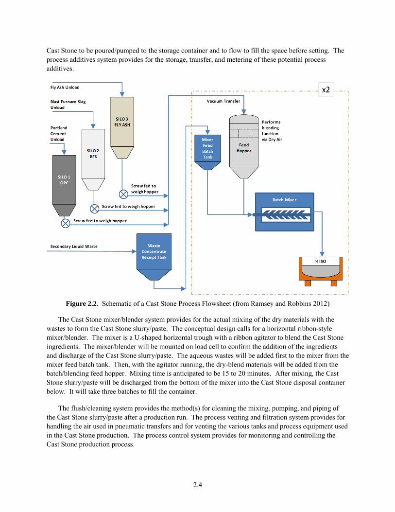
Figure 2.2 shows a simplified schematic of a Cast Stone process (Ramsey and Robbins 2012). The major equipment systems are described in detail in the ETF waste solidification unit conceptual design document (RPP-RPT-50967).
The dry materials handling, storage, and blending system is composed of storage silos for each of the individual dry materials including Portland cement, fly ash, and BFS. The dry materials are transferred pneumatically from the transport train/truck to the silos. From the individual silos, the dry materials are transferred mechanically by screw feeders to separate weigh hoppers where the individual dry components are weighed for each batch. From the weigh hoppers, the individual dry materials are moved using a vacuum pneumatic transfer system to one of two batch/blending feed hoppers where the dry materials are blended.
The waste storage, transfer and metering system receives waste from the upstream treatment/tank storage systems, maintains the wastes at the appropriate temperature and agitation, and provides for measured, quantitative transfers of the wastes to the Cast Stone mixer. The waste concentrate receipt tank receives waste from the ETF concentrate tanks and provides surge and feed capacity for the waste solidification unit. Two mixer feed batch tanks, one for each mixer, receive waste from the concentrate receipt tank and feed the wastes to the Cast Stone mixers. The feed batch tanks are sized to hold a single batch of waste feed for the Cast Stone mixer.
Under some conditions, it may be necessary to add some small quantities of chemicals to facilitate the mixing and pouring/pumping of the Cast Stone slurry/paste. These would be in the form of a fluidizer to reduce the viscosity of the slurry/paste, an air deentrainer to prevent excessive air entrainment that could lead to foaming or voids in the curing grout, and/or a set regulator to slow the curing process to allow the
2.4
Cast Stone to be poured/pumped to the storage container and to flow to fill the space before setting. The process additives system provides for the storage, transfer, and metering of these potential process additives.
Figure 2.2. Schematic of a Cast Stone Process Flowsheet (from Ramsey and Robbins 2012)
The Cast Stone mixer/blender system provides for the actual mixing of the dry materials with the wastes to form the Cast Stone slurry/paste. The conceptual design calls for a horizontal ribbon-style mixer/blender. The mixer is a U-shaped horizontal trough with a ribbon agitator to blend the Cast Stone ingredients. The mixer/blender will be mounted on load cell to confirm the addition of the ingredients and discharge of the Cast Stone slurry/paste. The aqueous wastes will be added first to the mixer from the mixer feed batch tank. Then, with the agitator running, the dry-blend materials will be added from the batch/blending feed hopper. Mixing time is anticipated to be 15 to 20 minutes. After mixing, the Cast Stone slurry/paste will be discharged from the bottom of the mixer into the Cast Stone disposal container below. It will take three batches to fill the container.
The flush/cleaning system provides the method(s) for cleaning the mixing, pumping, and piping of the Cast Stone slurry/paste after a production run. The process venting and filtration system provides for handling the air used in pneumatic transfers and for venting the various tanks and process equipment used in the Cast Stone production. The process control system provides for monitoring and controlling the Cast Stone production process.
3.1
3.0 Waste Form Qualification Testing Objectives
This section outlines the overall test objectives for a WFQ program for a secondary-waste Cast Stone waste form:
Provide for acceptance of the waste form at the Integrated Disposal Facility (IDF).
Optimize waste loading.
Demonstrate waste form over expected range of wastes.
Define and demonstrate the product control strategy.
Provide data to support risk and performance assessments.
The objectives are specific to qualification of the Cast Stone waste form for disposal in IDF. Although many test objectives for IDF disposal qualification and technology maturation coincide, this section does not include all of the testing required for technology maturation. In the discussions that follow, the “waste form” refers to the Cast Stone immobilization material itself. The “Cast Stone waste form package” refers to the Cast Stone waste form in a metal container and any fill material. A “Cast Stone disposal system" would include the Cast Stone waste form placed directly in a disposal vault that provides containment for the Cast Stone as it cures.
3.1 Provide for Acceptance of Waste Form at Integrated Disposal Facility
An important objective of waste form testing is to demonstrate that the waste form is acceptable for disposal in the IDF. Typically, a WFQ testing program includes activities before waste form production operations that demonstrate that the waste form will meet specifications and acceptance criteria. Then, during production operations, additional testing is conducted to confirm that the actual waste form meets the requirements.
To begin the WFQ process, it is necessary to identify relevant waste acceptance criteria and waste form specifications to outline the WFQ testing program. Draft waste acceptance criteria have been developed for the IDF for wastes to be accepted for disposal at the facility (RPP-8402, 2005). Also, the Washington State Department of Ecology, in Permit WA7890008967 (Ecology 2008), defines waste acceptance criteria for the IDF. Finally, the ILAW glass specifications in the WTP contract provide a source of waste form requirements. Appendix A provides the text of each requirement from the three sources and describes the strategy for demonstrating compliance with the requirements. Ultimately, a Secondary Waste Cast Stone Waste Form Compliance Plan will be prepared that provides detailed waste form and process qualification activities that will be conducted before and during production operations.
It is important to note that the current sources of relevant specifications for the ILAW all assume that the waste form is glass. In some cases, particularly those related to waste form leach testing, the equivalent performance and consistency specifications need to be developed for the Cast Stone waste form. The WFQ testing program will need to include testing within its scope to identify relevant test methods, precision and bias, and performance standards that can be used in establishing waste form requirements applicable to the Cast Stone waste form.
3.2
3.2 Optimize Waste Loading
To minimize total mission costs, one goal is to minimize the volume of the Cast Stone waste form to be disposed of in IDF. An objective of the waste form testing program is to then optimize the waste loading within the waste form while maintaining waste form properties to comply with specifications and acceptance criteria and to provide for efficient and controlled production of the waste form.
For the Cast Stone WFQ testing program, the waste loading will be optimized with respect to the amount of waste salts in the waste solution and the amount of waste water blended with the dry materials. The final disposal form (container versus vault) will impact this optimization. The ultimate objective is to reduce the number of waste units and total mass of the Cast Stone waste form while meeting waste form acceptance criteria and maintaining efficient operations.
3.3 Demonstrate Waste Form Over Expected Range of Wastes
The Hanford Site wastes to be solidified in the ETF vary in composition depending on the source. It is important to 1) understand how the range in waste compositions affects the Cast Stone process, 2) demonstrate that the process is sufficiently robust to handle the variability in the waste, and 3) identify any compositions or waste components that may have an adverse impact on the final waste form quality. This includes evaluating the products from treating a range of waste compositions and from processing over a range of operating conditions. An objective of the WFQ and technology maturation testing is to demonstrate that the Cast Stone process can accommodate the variations in waste composition.
3.4 Define and Demonstrate Product Control Strategy
Compliance with waste form specifications and land disposal restrictions can be demonstrated through direct waste form product sampling and characterization and/or through implementing a process/product control strategy that relies on controlling the Cast Stone process to produce an acceptable waste form product for disposal. Extensive, routine sampling of the Cast Stone product will be expensive and will increase risks to worker safety. Through a process control strategy, it may be feasible to achieve and demonstrate adequate waste form qualities without the risks associated with frequent direct sampling and testing of the final waste form. An important WFQ testing objective is then to define, develop, and demonstrate the product control strategies for the Cast Stone immobilization process.
3.5 Provide Data to Support Risk and Performance Assessments
Risk assessments and PAs are conducted to evaluate the potential impacts to the health and safety of the public, DOE and contractors’ employees, and the environment caused by the disposal of radioactive wastes. The secondary-waste Cast Stone waste form will be disposed of in the IDF on the Hanford Site. Data and updated source-term models are needed to support an IDF risk/PA that includes Cast Stone waste form disposal. Note that there will need to be iteration between the testing and predictive PA modeling as the program advances to the final licensing activities. Preliminary system PA sensitivity or probabilistic calculations will alert staff as to which parameters are most sensitive in controlling the risk or impact. This knowledge could require additional testing to improve the accuracy, reduce the range of
3.3
variation in the numerical values for the key parameters, and acquire more technically defensible “backup” or supporting information before the final PA is submitted to the regulators and stakeholders.
In conducting PAs, conceptual and computer models of the disposal system and surrounding environment are used to predict the movement of infiltration water, the evolution of the waste packages and repository components over time, and the fate of any leached contaminants through the vadose zone to the aquifer and ultimately back to the accessible environment. Once contaminants reach the accessible environment through various pathways, driven by chosen scenarios, doses or impacts are calculated and compared to various criteria. Sensitivity or probabilistic analyses are used to determine 1) a range of doses or impacts to account for variability in the myriad of input parameters, 2) limitations in the numerical algorithms (usually simplifications of controlling mechanisms) used to process the complex interactions that control the degradation or weathering of system components, and 3) scenario uncertainties that describe future conditions. Section 4.14 provides further descriptions of the IDF system PA conceptual models and codes that will be considered for performing the needed fate and transport predictions.
The various tests and solid-phase characterization activities used to support a PA identify the types and amounts of minerals and other solid phases that are present at the time of disposal and the changes in both as the waste packages weather in the long term. Therefore, more data and updated waste form release models are required to demonstrate the long-term performance of the Cast Stone waste form and the IDF repository.
The framework for modeling the long-term performance of cementitious waste forms has been treated in a fundamentally different manner than that for silicate-based glass and mineral forms (McGrail et al. 2003; Pierce et al. 2004). For glasses and mineral waste forms, the rate-controlling mechanism is matrix hydrolysis in which chemical bonds are broken and contaminants released. With cementitious waste forms, a physical model of contaminant diffusion has been almost universally adopted. Empirical effective diffusion coefficients measured in short-term laboratory experiments are widely used to model the long-term performance of cementitious waste forms (Albenesius 2001). The effective diffusion coefficients measured for each contaminant are used for a diffusion-controlled transport analysis in the continuous pore network of the Cast Stone coupled with diffusive-advective transport in idealized fractures. This approach is essentially equivalent to what has been performed for analysis of Saltstone at the Savannah River Site (Cook 2000).
The waste form tests required to support long-term risk assessment and PA start with well-constrained tests conducted on the Cast Stone waste form itself. These tests would include water leach tests and accelerated weathering tests that evaluate physical and mineralogical properties of the Cast Stone. Tests then progress to multicomponent tests that include the impacts of the waste container, other co-disposed waste forms, and the surrounding vadose zone sediments. Each test is used to a) identify the final solid phases and minerals formed by interaction of the starting solids with water and gases present in the surrounding sediment pores (i.e., the weathering process), b) identify a reaction network (the key minerals that form and the sequence of formation) for the Cast Stone waste form and waste package, or c) obtain the values for parameters required in the diffusive release or kinetic rate-law equations and the thermodynamic solubility and precipitation equations used by the waste form release algorithm to quantify the release of major and minor constituents in the Cast Stone waste form. Once the final solid phases and minerals that are formed by the weathering process are established and the kinetic rate-law and thermodynamic equilibrium equation parameters are established, a defensible conceptual model for
3.4
long-term waste form release can be constructed for the Cast Stone waste form. Predictions from the waste form release model will then be compared to the results of the multicomponent tests that include the waste container and IDF components and co-disposed wastes to verify that predictions are technically defensible. If the combined tests with waste form, container, co-disposed wastes, and sediments show that additional minerals form and control the release of contaminants from the Cast Stone waste form, these minerals will be included as end products in the overall IDF geochemical conceptual model.
The following subsections focus on describing the types of waste form characterization and tests needed to support predictive modeling of risk and long-term performance. In the early stages, the test specimens will be laboratory-scale specimens (mass ranging from tens to a few hundred grams, depending on the test) produced with simulated waste containing elevated concentrations of contaminants that facilitate their detection in both the solid-phase characterization and in the leachates obtained from the various leach tests. During the early stages of testing, a range of waste and “dry blend” masses and a range of waste loadings will be used to prepare test specimens. The resultant test specimens will be subjected to physical stability and contaminant leach testing to complement the efforts to optimize the Cast Stone waste form product. As the program progresses, the test samples will include products made from actual waste streams at the loadings expected to be used in final production of the optimized Cast Stone waste form. If required to make sure that leaching data can be obtained for all important contaminants, additional mass or radioactivity will be added to the actual wastes before solidification with optimized Cast Stone dry blend so that leachates contain concentrations above detection limits. Should field-scale, long-term testing of Cast Stone waste form monoliths be performed, it is recommended that intermediate-scale monoliths be placed in lysimeters that are backfilled with Hanford sediments. These intermediate-scale monoliths would be made from actual wastes at the optimum loading, if regulators allow, or otherwise with simulated wastes that are mixed with the optimized Cast Stone dry blend. Different field lysimeters should be subjected to various water infiltration rates, and all drainage should be collected as a function of time and analyzed for chemical and contaminant composition. At the end of all leach tests, the “weathered” Cast Stone waste form samples and surrounding sediment should be characterized and compared to unleached starting solids.
3.5.1 Solid-Phase Characterization
Detailed characterization of both unleached and leached Cast Stone waste form will be required to understand the starting mineralogy of the solids and the mineralogy present after exposure to leachants. Changes in physical properties such as total porosity, pore dimensions, tortuosity, compressive strength, hydraulic conductivity, and crack characteristics of the weathered Cast Stone will need to be measured and compared to the unweathered Cast Stone waste forms. Particular emphasis will be placed on determining the speciation of 99Tc and iodide (I−) in the Cast Stone product and the distribution of 99Tc and I− in the different Cast Stone solid and mineral phases and pore water. In particular, it will be determined whether the majority of the 99Tc is present in the weathered Cast Stone waste form in the reduced Tc(IV) state using synchrotron-based X-ray absorption spectroscopy (XAS) and whether the 99Tc is present in localized spots or homogeneously distributed using scanning electron microscopy–transmission electron microscopy–energy dispersive spectroscopy (SEM-TEM-EDS) microprobes.
By assimilating all the solid-phase characterization information and total chemical composition of unleached and leached Cast Stone waste form, one can better identify controlling mechanisms for species release and the solid-phase weathering sequence of the Cast Stone needed to support long-term
3.5
performance of the waste form. Should natural analogs for the Cast Stone waste form be found in the literature that are relevant to the expected weathering process in IDF, they will be compared and contrasted with the findings of this program to help support the discussion on long-term performance.
3.5.2 Waste Form Leach Testing
Leach tests are performed to evaluate the release of contaminants from the Cast Stone waste form. The tests provide data to aid in identifying the release mechanism and parameter values required in either diffusion-controlled rate-law equations or thermodynamic solubility-precipitation equations. The most appropriate leachants that will be encountered by IDF-disposed Cast Stone monoliths (and waste packages within metal containers) are vadose zone sediment pore water and co-disposed IDF-glass leachate. This assumes that the Cast Stone waste form will be co-disposed with IDF LAW glass, an assumption used in previous supplemental waste form risk assessments (Mann et al. 2003).
The main thrust needs to be leach testing of the multi-solid/mineral-phased optimized Cast Stone waste forms produced from pilot-scale tests that more truly reflect the thermal and curing environments under which the Cast Stone waste forms are generated. The multiphase leach testing will emphasize the study of the major constituents and the key contaminants of interest (Tc, I, nitrates, and RCRA metals).
3.5.3 Waste Package Release Testing
The chemical impacts of the presumed metal containers in which the Cast Stone waste form will be poured will be determined in similar tests as described in Section 3.5.2. In particular, the metal container will constrain water interactions with the Cast Stone waste form for some period of time and the reducing conditions initially present before the metal is totally weathered will slow transport of redox-sensitive contaminants such as Tc. In support of risk assessment and PA needs, the transport properties of contaminants within the entire Cast Stone waste package need to be understood to estimate release from the waste package to the disposal system.
3.5.4 Physical Stability
The long-term physical stability of the Cast Stone monolith once the outer metal container has deteriorated needs to be determined. The long-term physical stability of the monolith needs to be determined to evaluate landfill subsidence and the intruder scenarios as well as the possibility of cracks becoming frequent enough to change the system from diffusive-flux to advective-flux dominated. Traditionally, the long-term physical stability of Cast Stone monoliths has been evaluated with assumed crack degradation scenarios as opposed to direct long-term testing. As this program matures, the crack propagation issue will be evaluated to see whether a better long-term disposal test method can be developed.
3.5.5 Update Waste Form Release Conceptual Model and Code
A modified model for waste form release/radionuclide source terms must be developed and validated for inclusion in the future IDF PA codes. Cast Stone contaminant release conceptual models used at Hanford have been solely based on empirical diffusion-controlled release. Moving forward, these will be updated based on the combined chemical and physical conceptual models promoted by the Cementitious
3.6
Barriers Partnership (CBP) that incorporate physical cracking as well as solubility-precipitation chemical conceptual models along with diffusion-dominated mass transport. At this time it is not clear whether the CBP suite of computer codes (LeachXS-ORCHESTRA-STADIUM®-GoldSim) will be used or whether improvements will be made to the Subsurface Transport Over Multiphases (STOMP) code. Should the STOMP/eSTOMP code continue to be used, certain improvements will be added such as 1) thermodynamic data for key cementitious solid-solution phases available in the Objects Representing CHEmical Speciation and TRAnsport models (ORCHESTRA) thermodynamic database, and 2) the impacts of cracking, re-oxidation of redox sensitive COCs, oxidation of residual BFS, and carbonate weathering available in the Software for Transport and Degradation in Unsaturated Materials (STADIUM) code.
3.5.6 Adsorption Tests with Waste Form Leachates and Hanford Formation Sediments
The Cast Stone waste packages will be surrounded by other IDF waste packages (e.g., LAW glass) and Hanford formation sediments. The first tests will be classical batch adsorption tests and will be performed to investigate adsorption reactions among leachates from the Cast Stone waste form with the Hanford sediments. If warranted (based on system IDF PA predictions showing that the adsorption of key contaminants from Cast Stone waste packages is a sensitive process controlling the risk to groundwater and the accessible environment), flow-through column tests (both saturated and unsaturated water conditions) will be performed. If necessary and possible, surface complexation modeling and a sorption database, which accommodates the suspected varying background geochemical conditions, will be constructed from the adsorption experiments and literature.
3.5.7 Performance Assessment Model Validation
Model validation provides confidence that the computer code simulations are indicative of what is expected in the actual disposal environment. PA model validation work provides confidence that the predicted impacts of the disposal action are reasonable. To provide a basis for the validation effort, tests at laboratory and field scale are conducted to mimic the disposal system. Natural analog studies provide information on the weathering behavior of the waste form mineral phases in the environment over longer times than can be achieved in controlled experiments and testing.
4.1
4.0 Cast Stone Waste Form Qualification Testing Elements
To address the Cast Stone WFQ objectives outlined in Section 3.0, a testing program will be undertaken to provide the necessary data and process knowledge. A test matrix was developed identifying the WFQ objectives, the specific test objectives, and the testing and data to be obtained to meet those objectives. That matrix is provided in Appendix B. The test matrix identifies the specific scale of testing (laboratory, bench/engineering, pilot, or full scale); the types of simulants and the radionuclide and hazardous component spikes or actual wastes to use; and the specific product characterization tests to be conducted. There is some overlap in the test objectives, the scale, and the characterization tests outlined in the matrix. To facilitate test planning and scheduling, the various WFQ activities have been grouped into the following broad elements:
4.1 Cast Stone Waste Loading Tests 4.2 Cast Stone Process Control 4.3 Large-Scale Waste Form Package Tests 4.4 Land Disposal Restriction (LDR) Compliance Testing 4.5 Cast Stone Physical and Chemical Properties (Laboratory Scale) 4.6 Physical Stability 4.7 Waste Form Leaching Methods 4.8 Radionuclide Inventory Calculations 4.9 Cast Stone Solid-Phase Characterization 4.10 Waste Form Leach Testing – PA Support 4.11 Waste Package Release Testing 4.12 Waste Form Release Model 4.13 Batch Adsorption Tests 4.14 Validation of PA Predictions
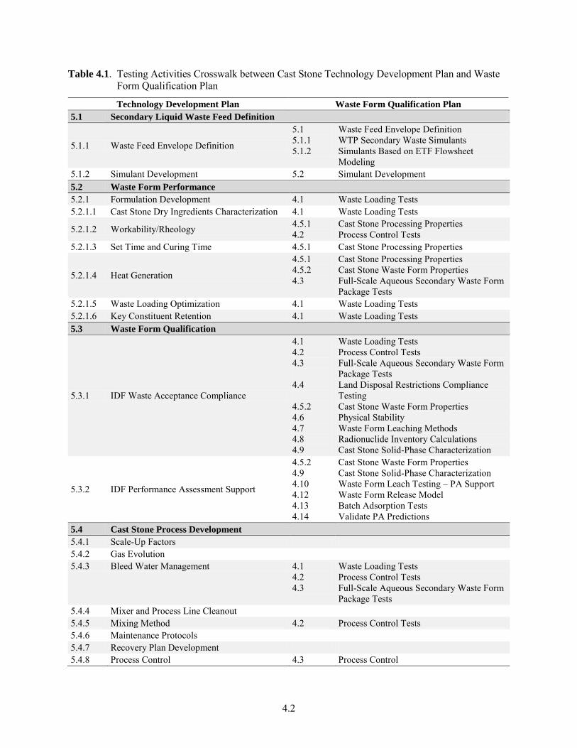
Each testing element is described in the sections that follow. Table 4.1 shows a crosswalk between the higher-level scope descriptions in the Secondary Liquid Waste Treatment Cast Stone Technology
Development Plan (Ramsey and Robbins 2012) and the testing elements above.
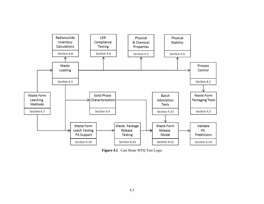
Figure 4.1 shows a general sequence for conducting the groups of tests. This is a higher level test logic. In conducting the testing, there will be iterations and feedback from larger-scale tests back to laboratory-scale tests where it may be more efficient to conduct specific tests to address specific questions as a result of the larger-scale testing. The focus of the diagram is the WFQ. The WFQ testing will be conducted within the larger technology maturation testing program. With the appropriate QA pedigree, testing conducted as part of the evaluation of supplemental treatment technologies and early technology maturation testing can be used to fulfill some of the WFQ testing objectives for the secondary-waste Cast Stone waste form.
In the discussions that follow, the Cast Stone product refers to the product from blending the aqueous secondary wastes with the dry materials and curing the resulting slurry/paste. The “waste form package” refers to the Cast Stone waste form in a metal container and any fill material or the Cast Stone poured and cured directly in a disposal vault.
4.2
Table 4.1. Testing Activities Crosswalk between Cast Stone Technology Development Plan and Waste Form Qualification Plan
Technology Development Plan Waste Form Qualification Plan
5.1 Secondary Liquid Waste Feed Definition
5.1.1 Waste Feed Envelope Definition
5.1 5.1.1 5.1.2
Waste Feed Envelope Definition WTP Secondary Waste Simulants Simulants Based on ETF Flowsheet Modeling
5.1.2 Simulant Development 5.2 Simulant Development 5.2 Waste Form Performance
5.2.1 Formulation Development 4.1 Waste Loading Tests 5.2.1.1 Cast Stone Dry Ingredients Characterization 4.1 Waste Loading Tests
5.2.1.2 Workability/Rheology 4.5.1 4.2
Cast Stone Processing Properties Process Control Tests
5.2.1.3 Set Time and Curing Time 4.5.1 Cast Stone Processing Properties
5.2.1.4 Heat Generation
4.5.1 4.5.2 4.3
Cast Stone Processing Properties Cast Stone Waste Form Properties Full-Scale Aqueous Secondary Waste Form Package Tests
5.2.1.5 Waste Loading Optimization 4.1 Waste Loading Tests 5.2.1.6 Key Constituent Retention 4.1 Waste Loading Tests 5.3 Waste Form Qualification
5.3.1 IDF Waste Acceptance Compliance
4.1 4.2 4.3 4.4 4.5.2 4.6 4.7 4.8 4.9
Waste Loading Tests Process Control Tests Full-Scale Aqueous Secondary Waste Form Package Tests Land Disposal Restrictions Compliance Testing Cast Stone Waste Form Properties Physical Stability Waste Form Leaching Methods Radionuclide Inventory Calculations Cast Stone Solid-Phase Characterization
5.3.2 IDF Performance Assessment Support
4.5.2 4.9 4.10 4.12 4.13 4.14
Cast Stone Waste Form Properties Cast Stone Solid-Phase Characterization Waste Form Leach Testing – PA Support Waste Form Release Model Batch Adsorption Tests Validate PA Predictions
5.4 Cast Stone Process Development
5.4.1 Scale-Up Factors 5.4.2 Gas Evolution 5.4.3 Bleed Water Management 4.1
4.2 4.3
Waste Loading Tests Process Control Tests Full-Scale Aqueous Secondary Waste Form Package Tests
5.4.4 Mixer and Process Line Cleanout 5.4.5 Mixing Method 4.2 Process Control Tests 5.4.6 Maintenance Protocols 5.4.7 Recovery Plan Development 5.4.8 Process Control 4.3 Process Control
4.3
Figure 4.1. Cast Stone WFQ Test Logic
4.4
The waste form testing objectives will be defined and characterized below as they relate to six primary testing scales. These are, in order of complexity, calculation or analysis, laboratory-scale testing, bench-scale testing, engineering- or pilot-scale testing, full-scale component testing, and production hot operations.
The calculation or analysis approach is intended to capture the research activities that are performed before testing on the laboratory or demonstration scale. These may include engineering calculations, literature reviews, dose calculations, and modeling and other paper studies with the emphasis on understanding the science and mechanisms of the objectives to be tested or demonstrated in the laboratory.
The laboratory-scale testing approach is intended to capture initial technology development and chemical analysis. This testing approach may include chemical analysis, measurement of heat of reaction, Cast Stone dry blend mix and waste/dry blend mix formulation, leach testing, and WFQ testing.
Bench-scale testing is intended to demonstrate that the basic components or operations will work together as a system to validate or achieve desired testing objectives. At this scale, the test platform could fit on a modified bench and provide Cast Stone specimens in the one- to five-gallon (four- to twenty-liter) size.
Pilot-scale testing is intended to validate the system in the relevant operating environment. This represents a major step in the technology’s demonstrated readiness. The pilot scale represents the step-up from laboratory scale to engineering scale. This prototype should be capable of performing all the functions that will be required of the system, as this prototype should be used to determine scaling factors that will be used in designing the final waste processing system. The operating environment of this testing platform should closely represent the actual operating environment. At this scale, the facility may be capable of generating 200 liters or more of Cast Stone product over a single day.
Full-scale testing demonstrates an actual system prototype. This test platform is virtually complete and will be used to validate the waste form immobilization processes under all operating conditions and environments.
Production hot operations demonstrate the actual system operating over the full range of expected conditions. The test platform is in its final form and will be operated with a full range of wastes in hot operations.
4.1 Waste Loading Tests
The Cast Stone waste loading test group is composed of the tests required to determine and demonstrate waste immobilization in the Cast Stone waste form. These tests may include laboratory-scale formulation of waste/dry blends for optimal waste loading and technology and process demonstration on a pilot-scale platform to validate waste loading. These tests will 1) emphasize the optimization of the concentration of waste in the Cast Stone product, 2) determine the impacts of waste components and waste variability on the Cast Stone product, and 3) demonstrate successful waste solidification over the expected range of waste compositions. Testing at this scale will also support PA analyses and will provide data to address LDRs.
4.5
The first test objective is to optimize the waste loading within the Cast Stone product. Initial formulation activities will be performed at the laboratory scale using a full range of simulants representing the expected variability in the secondary-waste feed. Bench and/or pilot-scale test activities may be performed on simulated and spiked aqueous ETF treated waste feeds to fully characterize the waste loading in the Cast Stone. All processing parameters affecting the Cast Stone product will be measured, and the Cast Stone waste form will be fully characterized and leach tested to verify immobilization of COCs at optimized loading formulations.
An important aspect of this first objective is to identify sources of Cast Stone dry materials (fly ash, BFS, and cement) and evaluate their availability, quality and variability. Testing will be conducted to determine the impacts of the variability on the properties of the resulting Cast Stone processing characteristics and final product quality.
The second objective is to determine acceptable curing conditions for the Cast Stone waste form. The effects of temperature, humidity conditions, and cure time will be evaluated. The heat of hydration/formation will be determined.
The third objective is to determine process control parameters for Cast Stone process testing at larger scales. Testing at a laboratory scale will evaluate the impacts of variability in controlling the mix ratios for the waste and dry material components. The goals in optimizing the Cast Stone formulation are to maximize the waste loading, achieve a minimum 500 psi compressive strength, and maintain slurry properties to allow for mixing, pumping, and flow into the waste form container or vault.
The Cast Stone waste form will have to meet LDR requirements. An important test objective will be to demonstrate that the Cast Stone waste form will pass Toxicity Characteristic Leaching Procedure (TCLP) tests for RCRA metals and underlying hazardous constituents. Initial WFQ activities will be performed at the bench scale using a range of simulants, spiked with RCRA metals and other hazardous constituents, representing variability in the waste feed. Selected representative actual waste samples will also be used in the laboratory-scale testing. The Cast Stone waste form will be fully characterized and leach tested to verify that the product will meet requirements for LDRs. This will include TCLP testing and may include additional characterization using new U.S. Environmental Protection Agency (EPA) methods including 1313 (EPA 2009a), 1314 (EPA 2009b), 1315 (EPA 2009c), and 1316 (EPA 2009d). Further details of testing to address LDR requirements are discussed in Section 4.4.
Pilot- and full-scale testing of the Cast Stone process and container filling may indicate the need for adjustments to the Cast Stone formulation to improve the rheology and flowability of the Cast Stone paste/slurry and/or to adjust the set and cure times. Should it be indicated by the testing, additives such as set retarders and superplasticizers may be evaluated to improve the processing characteristics of the Cast Stone. This iterative feedback loop between the waste loading/formulation work at lab/bench scale and the confirmatory testing done and engineering-scale is anticipated as part of the overall technology development plan (Ramsey and Robbins 2012).
Similarly, leach testing and radionuclide retention studies may indicate the need for additives to reduce the release rate of COCs. Should it be indicated by the testing, additives that control redox or pore size or otherwise act as getters may be evaluated to improve the retention of contaminants in the Cast Stone waste form.
4.6
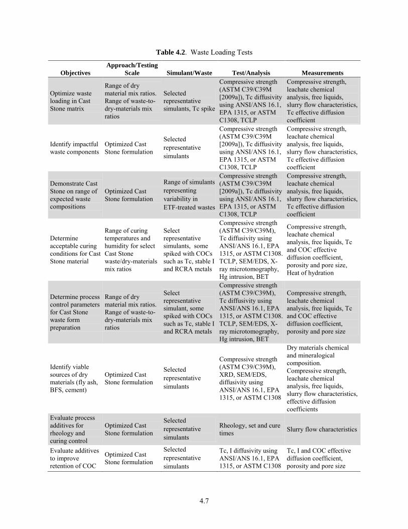
Table 4.2 summarizes the tests to be conducted to address the Cast Stone waste loading test objectives. This group of tests includes activities 1.1, 2.1, 3.1, 3.2, 3.3, and 14.1 in Table B.1 of Appendix B.
4.2 Process Control Tests
The Cast Stone process includes all the technologies and processes required for 1) handling and delivering dry materials components, and the waste solution, 2) mixing dry components and aqueous waste solution, 3) pouring slurry into storage containers, and 4) curing final waste forms. The test objectives described below represent a group of tests required to demonstrate the control of waste/dry-materials mixing, transfer, and slurry discharge into the final container and the control of the dry materials mix ratios and composition for the generation of waste forms that satisfy IDFWAC. The testing will be coordinated with the engineering-scale testing planned to support design activities for the Cast Stone waste solidification unit.3
These tests will be performed on a pilot-scale testing platform. The pilot-scale testing will validate the system in the relevant operating environments. This represents a major step in the technology’s demonstrated readiness. This prototype should be capable of performing all the functions that will be required of the system, as this prototype should be used to validate scaling factors that will be used to design the full-scale system. The operating environment of this testing platform should closely represent the actual operating environment.
A pilot-scale testing platform of the Cast Stone process will be used to demonstrate the control of container filling to prevent or minimize overfill and spillage while simultaneously minimizing gross void spaces within the finalized waste form.
This pilot-scale testing platform will be used to demonstrate the control of dry materials mix ratios and composition. Initial testing performed in the laboratory (see Section 4.1) will be used to optimize the Cast Stone formulation with respect to waste loading and to minimize free liquid formation during curing. Waste/dry-materials mix control testing on the pilot-scale platform will include examining filled containers during curing for the formation of free liquids.
An objective of the Cast Stone process-control strategy is to demonstrate the operating envelope for the Cast Stone immobilization process. The Cast Stone process operating envelope will be demonstrated on a range of waste compositions and waste/dry-materials mix ratios. The cured Cast Stone waste form will be characterized and those waste forms containing the key COCs will be leach tested to demonstrate predicted immobilization.
Related to the demonstration of the Cast Stone process operating envelope is the demonstration of Cast Stone slurry/paste flow characteristics. This test objective is concerned with demonstrating transfer, pumpability, and flow into the waste form package of the Cast Stone slurry (composed of aqueous waste solution and dry material mix). The slurry transfer will be demonstrated on a range of Cast Stone slurries consisting of various blend ratios of differing wastes and dry materials mixes.
3 Ashley, T. 2012. Cast Stone Engineering Test Plan for Secondary Waste Treatment Project (T3W08), RPP-Plan-51770, Rev. B, ARES Corporation for Washington River Protection Solutions, LLC, Richland, Washington.
4.7
Table 4.2. Waste Loading Tests
Objectives
Approach/Testing
Scale Simulant/Waste Test/Analysis Measurements
Optimize waste loading in Cast Stone matrix
Range of dry material mix ratios. Range of waste-to-dry-materials mix ratios
Selected representative simulants, Tc spike
Compressive strength (ASTM C39/C39M [2009a]), Tc diffusivity using ANSI/ANS 16.1, EPA 1315, or ASTM C1308, TCLP
Compressive strength, leachate chemical analysis, free liquids, slurry flow characteristics, Tc effective diffusion coefficient
Identify impactful waste components
Optimized Cast Stone formulation
Selected representative simulants
Compressive strength (ASTM C39/C39M [2009a]), Tc diffusivity using ANSI/ANS 16.1, EPA 1315, or ASTM C1308, TCLP
Compressive strength, leachate chemical analysis, free liquids, slurry flow characteristics, Tc effective diffusion coefficient
Demonstrate Cast Stone on range of expected waste compositions
Optimized Cast Stone formulation
Range of simulants representing variability in ETF-treated wastes
Compressive strength (ASTM C39/C39M [2009a]), Tc diffusivity using ANSI/ANS 16.1, EPA 1315, or ASTM C1308, TCLP
Compressive strength, leachate chemical analysis, free liquids, slurry flow characteristics, Tc effective diffusion coefficient
Determine acceptable curing conditions for Cast Stone material
Range of curing temperatures and humidity for select Cast Stone waste/dry-materials mix ratios
Select representative simulants, some spiked with COCs such as Tc, stable I and RCRA metals
Compressive strength (ASTM C39/C39M), Tc diffusivity using ANSI/ANS 16.1, EPA 1315, or ASTM C1308. TCLP, SEM/EDS, X-ray microtomography, Hg intrusion, BET
Compressive strength, leachate chemical analysis, free liquids, Tc and COC effective diffusion coefficient, porosity and pore size, Heat of hydration
Determine process control parameters for Cast Stone waste form preparation
Range of dry material mix ratios. Range of waste-to-dry-materials mix ratios
Select representative simulant, some spiked with COCs such as Tc, stable I and RCRA metals
Compressive strength (ASTM C39/C39M), Tc diffusivity using ANSI/ANS 16.1, EPA 1315, or ASTM C1308. TCLP, SEM/EDS, X-ray microtomography, Hg intrusion, BET
Compressive strength, leachate chemical analysis, free liquids, Tc and COC effective diffusion coefficient, porosity and pore size
Identify viable sources of dry materials (fly ash, BFS, cement)
Optimized Cast Stone formulation
Selected representative simulants
Compressive strength (ASTM C39/C39M), XRD, SEM/EDS, diffusivity using ANSI/ANS 16.1, EPA 1315, or ASTM C1308
Dry materials chemical and mineralogical composition. Compressive strength, leachate chemical analysis, free liquids, slurry flow characteristics, effective diffusion coefficients
Evaluate process additives for rheology and curing control
Optimized Cast Stone formulation
Selected representative simulants
Rheology, set and cure times Slurry flow characteristics
Evaluate additives to improve retention of COC
Optimized Cast Stone formulation
Selected representative simulants
Tc, I diffusivity using ANSI/ANS 16.1, EPA 1315, or ASTM C1308
Tc, I and COC effective diffusion coefficient, porosity and pore size
4.8
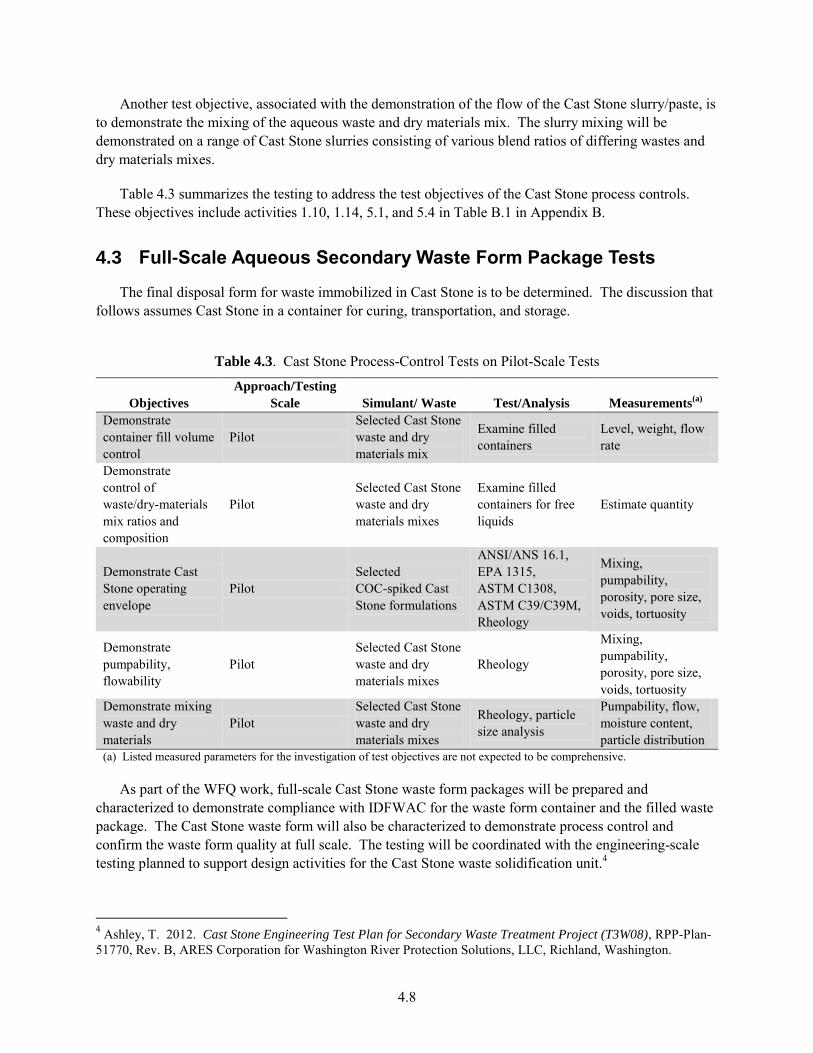
Another test objective, associated with the demonstration of the flow of the Cast Stone slurry/paste, is to demonstrate the mixing of the aqueous waste and dry materials mix. The slurry mixing will be demonstrated on a range of Cast Stone slurries consisting of various blend ratios of differing wastes and dry materials mixes.
Table 4.3 summarizes the testing to address the test objectives of the Cast Stone process controls. These objectives include activities 1.10, 1.14, 5.1, and 5.4 in Table B.1 in Appendix B.
4.3 Full-Scale Aqueous Secondary Waste Form Package Tests
The final disposal form for waste immobilized in Cast Stone is to be determined. The discussion that follows assumes Cast Stone in a container for curing, transportation, and storage.
Table 4.3. Cast Stone Process-Control Tests on Pilot-Scale Tests
Objectives
Approach/Testing
Scale Simulant/ Waste Test/Analysis Measurements(a)
Demonstrate container fill volume control
Pilot Selected Cast Stone waste and dry materials mix
Examine filled containers
Level, weight, flow rate
Demonstrate control of waste/dry-materials mix ratios and composition
Pilot Selected Cast Stone waste and dry materials mixes
Examine filled containers for free liquids
Estimate quantity
Demonstrate Cast Stone operating envelope
Pilot Selected COC-spiked Cast Stone formulations
ANSI/ANS 16.1, EPA 1315, ASTM C1308, ASTM C39/C39M, Rheology
Mixing, pumpability, porosity, pore size, voids, tortuosity
Demonstrate pumpability, flowability
Pilot Selected Cast Stone waste and dry materials mixes
Rheology
Mixing, pumpability, porosity, pore size, voids, tortuosity
Demonstrate mixing waste and dry materials
Pilot Selected Cast Stone waste and dry materials mixes
Rheology, particle size analysis
Pumpability, flow, moisture content, particle distribution
(a) Listed measured parameters for the investigation of test objectives are not expected to be comprehensive.
As part of the WFQ work, full-scale Cast Stone waste form packages will be prepared and characterized to demonstrate compliance with IDFWAC for the waste form container and the filled waste package. The Cast Stone waste form will also be characterized to demonstrate process control and confirm the waste form quality at full scale. The testing will be coordinated with the engineering-scale testing planned to support design activities for the Cast Stone waste solidification unit.4
4 Ashley, T. 2012. Cast Stone Engineering Test Plan for Secondary Waste Treatment Project (T3W08), RPP-Plan-51770, Rev. B, ARES Corporation for Washington River Protection Solutions, LLC, Richland, Washington.
4.9
The first objective is to demonstrate that the waste form container complies with IDFWAC. The container must meet requirements with respect to materials of construction, labeling, closure and sealing, and package lifting and handling. Prototypic waste form packages will be fabricated and filled as part of full-scale testing of the preparation process for the Cast Stone waste form. The functionality of the waste form container features will be demonstrated.
The second objective is to determine the gross characteristics of the filled waste package, including mass, fill height, and void space as well as the presence of any free liquids.
The third objective is to characterize the temperature profile in the waste package as the container is filled and as the Cast Stone cures. Temperatures will be measured at the container wall and various locations within the waste form to determine the wall temperature and cooling curves for the Cast Stone. The results will be compared with laboratory evaluations of curing conditions to confirm that the temperature profile does not affect waste form quality.
The fourth objective is to identify any macroscopic inhomogeneities in the Cast Stone waste form. The filled container will be destructively examined for large voids, bubbles, and cracking as well as for evidence of layering. Waste form samples from various locations will be examined for evidence of settling and segregation and for variation in porosity and pore size.
The fifth objective is to demonstrate consistency in the waste form characteristics throughout the full-scale waste form package. Samples of the Cast Stone waste form from various locations within the package will be characterized with respect to chemical and mineral composition and leachability.
Table 4.4 shows the WFQ testing to be conducted on full-scale prototypic Cast Stone waste form packages. This group of tests includes activities 1.4, 1.5, 1.10, 1.11, 1.12, 1.13, 1.14, 1.27, 7.6, 14.3, and 14.4 in Table B.1 in Appendix B.
4.4 Land Disposal Restrictions Compliance Testing
The Cast Stone waste form LDR compliance testing will provide the process demonstration and waste form product data to demonstrate that the Cast Stone waste form meets the land disposal restrictions in 40 CFR 268 and WAC 173-303-140. The Cast Stone waste solidification unit will solidify wastes from the Liquid Effluent Retention Facility (LERF) and ETF aqueous waste treatment system and from secondary wastes from the WTP pretreatment process condensates and LAW vitrification secondary off-gas treatment system condensates.
The LERF stores and treats the 242-A evaporator condensate and dilute aqueous waste streams from other Hanford Facility generating units until further treatment is conducted in ETF. These could include contaminated groundwater from pump-and-treat remediation activities, water from deactivation activities, laboratory aqueous waste from unused samples and sample analyses, and leachate from landfills such as the ERDF. The 242-A evaporator process condensate is regulated as a mixed waste because of the “derived from” rule from treating Double-Shell Tanks System waste (DOE-RL 1997). The LERF could receive multi-source leachate (F039), which is derived from nonspecific source wastes F001 through F005. The process condensate and/or other influent waste streams also could display the state-only criteria of toxicity (WT01 or WT02).
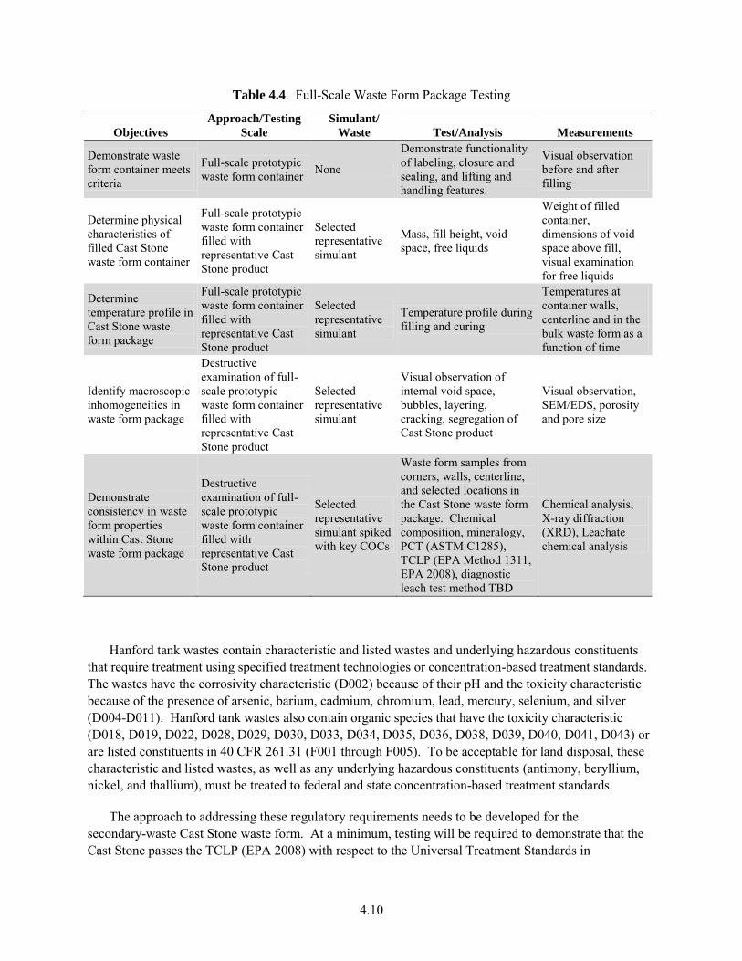
4.10
Table 4.4. Full-Scale Waste Form Package Testing
Objectives
Approach/Testing
Scale
Simulant/
Waste Test/Analysis Measurements
Demonstrate waste form container meets criteria
Full-scale prototypic waste form container None
Demonstrate functionality of labeling, closure and sealing, and lifting and handling features.
Visual observation before and after filling
Determine physical characteristics of filled Cast Stone waste form container
Full-scale prototypic waste form container filled with representative Cast Stone product
Selected representative simulant
Mass, fill height, void space, free liquids
Weight of filled container, dimensions of void space above fill, visual examination for free liquids
Determine temperature profile in Cast Stone waste form package
Full-scale prototypic waste form container filled with representative Cast Stone product
Selected representative simulant
Temperature profile during filling and curing
Temperatures at container walls, centerline and in the bulk waste form as a function of time
Identify macroscopic inhomogeneities in waste form package
Destructive examination of full-scale prototypic waste form container filled with representative Cast Stone product
Selected representative simulant
Visual observation of internal void space, bubbles, layering, cracking, segregation of Cast Stone product
Visual observation, SEM/EDS, porosity and pore size
Demonstrate consistency in waste form properties within Cast Stone waste form package
Destructive examination of full-scale prototypic waste form container filled with representative Cast Stone product
Selected representative simulant spiked with key COCs
Waste form samples from corners, walls, centerline, and selected locations in the Cast Stone waste form package. Chemical composition, mineralogy, PCT (ASTM C1285), TCLP (EPA Method 1311, EPA 2008), diagnostic leach test method TBD
Chemical analysis, X-ray diffraction (XRD), Leachate chemical analysis
Hanford tank wastes contain characteristic and listed wastes and underlying hazardous constituents that require treatment using specified treatment technologies or concentration-based treatment standards. The wastes have the corrosivity characteristic (D002) because of their pH and the toxicity characteristic because of the presence of arsenic, barium, cadmium, chromium, lead, mercury, selenium, and silver (D004-D011). Hanford tank wastes also contain organic species that have the toxicity characteristic (D018, D019, D022, D028, D029, D030, D033, D034, D035, D036, D038, D039, D040, D041, D043) or are listed constituents in 40 CFR 261.31 (F001 through F005). To be acceptable for land disposal, these characteristic and listed wastes, as well as any underlying hazardous constituents (antimony, beryllium, nickel, and thallium), must be treated to federal and state concentration-based treatment standards.
The approach to addressing these regulatory requirements needs to be developed for the secondary-waste Cast Stone waste form. At a minimum, testing will be required to demonstrate that the Cast Stone passes the TCLP (EPA 2008) with respect to the Universal Treatment Standards in
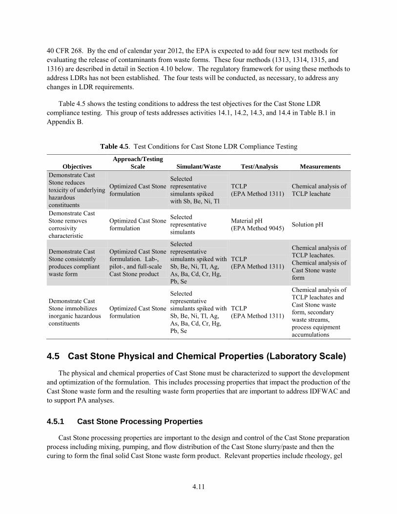
4.11
40 CFR 268. By the end of calendar year 2012, the EPA is expected to add four new test methods for evaluating the release of contaminants from waste forms. These four methods (1313, 1314, 1315, and 1316) are described in detail in Section 4.10 below. The regulatory framework for using these methods to address LDRs has not been established. The four tests will be conducted, as necessary, to address any changes in LDR requirements.
Table 4.5 shows the testing conditions to address the test objectives for the Cast Stone LDR compliance testing. This group of tests addresses activities 14.1, 14.2, 14.3, and 14.4 in Table B.1 in Appendix B.
Table 4.5. Test Conditions for Cast Stone LDR Compliance Testing
Objectives
Approach/Testing
Scale Simulant/Waste Test/Analysis Measurements
Demonstrate Cast Stone reduces toxicity of underlying hazardous constituents
Optimized Cast Stone formulation
Selected representative simulants spiked with Sb, Be, Ni, Tl
TCLP (EPA Method 1311)
Chemical analysis of TCLP leachate
Demonstrate Cast Stone removes corrosivity characteristic
Optimized Cast Stone formulation
Selected representative simulants
Material pH (EPA Method 9045) Solution pH
Demonstrate Cast Stone consistently produces compliant waste form
Optimized Cast Stone formulation. Lab-, pilot-, and full-scale Cast Stone product
Selected representative simulants spiked with Sb, Be, Ni, Tl, Ag, As, Ba, Cd, Cr, Hg, Pb, Se
TCLP (EPA Method 1311)
Chemical analysis of TCLP leachates. Chemical analysis of Cast Stone waste form
Demonstrate Cast Stone immobilizes inorganic hazardous constituents
Optimized Cast Stone formulation
Selected representative simulants spiked with Sb, Be, Ni, Tl, Ag, As, Ba, Cd, Cr, Hg, Pb, Se
TCLP (EPA Method 1311)
Chemical analysis of TCLP leachates and Cast Stone waste form, secondary waste streams, process equipment accumulations
4.5 Cast Stone Physical and Chemical Properties (Laboratory Scale)
The physical and chemical properties of Cast Stone must be characterized to support the development and optimization of the formulation. This includes processing properties that impact the production of the Cast Stone waste form and the resulting waste form properties that are important to address IDFWAC and to support PA analyses.
4.5.1 Cast Stone Processing Properties
Cast Stone processing properties are important to the design and control of the Cast Stone preparation process including mixing, pumping, and flow distribution of the Cast Stone slurry/paste and then the curing to form the final solid Cast Stone waste form product. Relevant properties include rheology, gel
4.12
and hardening time, temperature rise, and free/bleed water. The protocols for laboratory-, bench-, and engineering scale need to be aligned such that there is confidence that the results at the different scales are the same or the differences are understood.
The rheology of the Cast Stone slurry/paste is important for sizing the mixers and pumps used in preparing the Cast Stone. In the laboratory, the viscosity of the slurry/paste is measured with a rheometer. The viscosity and yield stress are measured over a period of time to determine how the rheological properties change as the Cast Stone hydration reactions proceed and the slurry/paste begins to stiffen. Larger-scale flow tests (see Section 4.2) demonstrate that the slurry/paste is sufficiently fluid to flow to the corners in the final disposal container.
Curing times for cementitious material are typically described in terms of an initial and final set time. The initial set time is the time when the paste begins to stiffen and retain its shape. The final set time is the time at which the paste has hardened sufficiently to resist a known pressure without deforming. Various simple slump and pour tests can be used to determine this gel time. ASTM C191 (ASTM 2008c) uses the Vicat needle test to determine both the initial and final set time. The slump and pour tests and the Vicat needle test provide indications of the stiffening process at discrete time intervals. A technique based on ultrasonic wave reflection has been used to provide continuous monitoring of the Cast Stone early hydration and stiffening (Sundaram et al. 2011).
The hydration reactions as the cement and fly ash interact with the aqueous wastes generate heat during the Cast Stone curing process. This heat must be dissipated during the curing process so that the Cast Stone does not reach temperatures that can be deleterious to the final waste form. Adiabatic and isothermal calorimetry are used to determine the amount of heat generated by the hydration reactions. Thermal conductivity and heat capacity are then needed to estimate the expected temperature rise. Alternatively, the temperature rise can be measured directly with thermocouples with corrections for heat loss from the specimens during the measurements.
Some bleed water or free water may form during the initial curing of the Cast Stone. Normally, this water is needed for the hydration/curing process and will disappear over a few days. Beyond that time, free liquids suggest that there is too much water in the formulation and adjustments must be made. Free water is typically observed visually.
4.5.2 Cast Stone Waste Form Properties
Characterization of the Cast Stone waste form properties and their changes due to weathering and other environmental conditions are addressed in several sections of the testing plan. This section addresses waste form properties that may be needed for various engineering calculations and other analyses. They include:
density
porosity/pore size
hydraulic conductivity
thermal conductivity
heat capacity
4.13
The physical and chemical properties of the Cast Stone must be characterized to address slurry/paste properties important to processing and final waste form properties to address waste acceptance criteria for the IDF and to support PA analyses. Many of these properties can be determined on Cast Stone samples prepared in the laboratory and from Cast Stone specimens cut from engineering- and pilot-scale tests. Table 4.6 summarizes the laboratory-scale testing to characterize the Cast Stone physical and chemical properties. This group of tests includes activities 1.4, 1.6, 1.13, 1.21, 1.22, 1.25, 7.4, 7.5, 7.6, and 10.1 in Table B.1 in Appendix B.
4.6 Physical Stability
There is an IDF acceptance requirement for compressive strength of the waste forms destined for final disposal in IDF. The requirement is: “The mean compressive strength of the waste form shall be determined by testing representative nonradioactive samples. The compressive strength shall be at least 3.45 MPa when tested in accordance with ASTM C39/C39M-99 or an equivalent method.” Waste or waste packages destined for burial in IDF must have structural stability. Structural stability can be provided by the waste form itself, by processing the waste to a stable form, or by placing the waste in a disposal container or structure that provides stability after disposal.
In support of both the IDF waste package acceptance criteria and long-term stability assessments, Cast Stone waste form monoliths made with un-spiked simulants and monoliths that have been subjected to accelerated weathering cycles (see discussions in NRC 1991 and Um et al. 2011) will be compression strength tested using ASTM C39/C39M methodology ASTM (2009a). The U.S. Nuclear Regulatory Commission (NRC) regulations for low-level nuclear waste [10 CFR 61.56(b)(1)] state that “a structurally stable waste package will generally maintain its physical dimensions and form, under the expected disposal conditions such as weight of overburden and compaction equipment, the presence of moisture and microbial activity, and internal factors such as radiation effects and chemical changes” for at least 300 years. The NRC branch technical position guidance (NRC 1991) recommends that waste packages have at least 3.45 MPa (500 psi) compressive strength and that after various stresses, such as freeze-thaw cycling, water immersion, biodegradation, and radiation exposure, the compressive strength does not diminish below 75% of its prestressed state. Of particular interest to this project will be impacts of carbonation (absorption and reaction of atmospheric CO2) and sulfates on the Cast Stone waste form. Several laboratory-scale Cast Stone waste form specimens will be alternately reacted in high CO2 atmospheres under relative humidity conditions conducive of accelerating carbon dioxide reactions and then drying for several cycles. The resultant monoliths will be tested for compressive strength and after specimens have been forced to fail, they will be profiled and detailed characterization of the mineralogy (using XRD), porosity, and pore throat size distributions (using microtomography, SEM, and Hg intrusion techniques) and depth profiles of the carbonation and pH fronts will be measured.
The compressive strength test protocol uses cylindrical monoliths, most commonly with dimensions 2-in. diameter by 4-in. length. The right-circular-cylinder monoliths are placed in the test apparatus, and a compressive axial load is applied at a rate that is within a prescribed range until failure occurs. Compression tests of moist Cast Stone waste form specimens should be made as soon as practicable after removal from the curing molds, or alternatively, test specimens shall be kept moist by any convenient method during the period between removal from the curing molds or accelerated weathering cycling processes and the compressive strength testing.
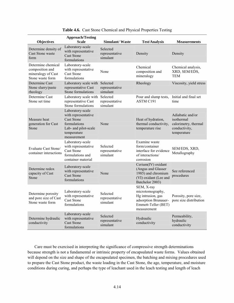
4.14
Table 4.6. Cast Stone Chemical and Physical Properties Testing
Objectives
Approach/Testing
Scale Simulant/ Waste Test/Analysis Measurements
Determine density of Cast Stone waste form
Laboratory-scale with representative Cast Stone formulations
Selected representative simulant
Density Density
Determine chemical composition and mineralogy of Cast Stone waste form
Laboratory-scale with representative Cast Stone formulations
None Chemical composition and mineralogy
Chemical analysis, XRD, SEM/EDS, TEM
Determine Cast Stone slurry/paste rheology
Laboratory scale with representative Cast Stone formulations
Selected representative simulant
Rheology Viscosity, yield stress
Determine Cast Stone set time
Laboratory scale with representative Cast Stone formulations
Selected representative simulant
Pour and slump tests, ASTM C191
Initial and final set time
Measure heat generation for Cast Stone
Laboratory-scale with representative Cast Stone formulations Lab- and pilot-scale temperature measurement
None Heat of hydration, thermal conductivity, temperature rise
Adiabatic and/or isothermal calorimetry, thermal conductivity, temperature
Evaluate Cast Stone/ container interactions
Laboratory-scale with representative Cast Stone formulations and container material
Selected representative simulant
Examine waste form/container interface for evidence of interactions/ corrosion
SEM/EDS, XRD, Metallography
Determine redox capacity of Cast Stone
Laboratory-scale with representative Cast Stone formulations
None
Cerium(IV) oxidant (Angus and Glasser 1985) and chromium (VI) oxidant (Lee and Batchelor 2003)
See referenced procedures
Determine porosity and pore size of Cast Stone waste form
Laboratory-scale with representative Cast Stone formulations
Selected representative simulant
SEM, X-ray microtomography, Hg intrusion, gas adsorption Brunauer-Emmett-Teller (BET) measurement
Porosity, pore size, pore size distribution
Determine hydraulic conductivity
Laboratory-scale with representative Cast Stone formulations
Selected representative simulant
Hydraulic conductivity
Permeability, hydraulic conductivity
Care must be exercised in interpreting the significance of compressive strength determinations because strength is not a fundamental or intrinsic property of encapsulated waste forms. Values obtained will depend on the size and shape of the encapsulated specimen, the batching and mixing procedures used to prepare the Cast Stone product, the waste loading in the Cast Stone, the age, temperature, and moisture conditions during curing, and perhaps the type of leachant used in the leach testing and length of leach
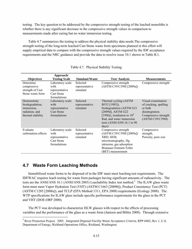
4.15
testing. The key question to be addressed by the compressive strength testing of the leached monoliths is whether there is any significant decrease in the compressive strength values in comparison to measurements made after curing but no water immersion testing.
Table 4.7 summarizes the testing to address the physical stability data needs.The compressive strength testing of the long-term leached Cast Stone waste form specimens planned in this effort will supply empirical data to compare with the compressive strength values required by the IDF acceptance requirements and the NRC guidance and provide the data to resolve issue 10.1 shown in Table B.1.
Table 4.7. Physical Stability Testing
Objectives
Approach/
Testing Scale Simulant/Waste Test/ Analysis Measurements
Determine compressive strength of Cast Stone waste form
Laboratory scale with representative Cast Stone formulations
Selected representative simulant
Compressive strength (ASTM C39/C39M [2009a])
Compressive strength
Demonstrate biodegradation, immersion, radiation, and thermal stability
Laboratory scale with representative Cast Stone formulations
Selected representative simulant
Thermal cycling (ASTM B553 [1985]), biodegradation (ASTM G21 [2009d], ASTM G22 [1996]), irradiation to 108 Rad, and water immersion tests (ANSI/ANS 16.1 to 90 days)
Visual examination of cracking, spalling or bulk disintegration. Compressive strength (ASTM C39/C39M)
Evaluate carbonation effects
Laboratory scale with representative Cast Stone formulations
Selected representative simulant
Compressive strength (ASTM C39/C39M [2009a]) XRD, SEM, microtomography, Hg intrusion, gas adsorption Brunauer-Emmett-Teller (BET) measurement
Compressive strength, Porosity, pore size
4.7 Waste Form Leaching Methods
Immobilized waste forms to be disposed of in the IDF must meet leaching test requirements. The IDFWAC requires leach testing for waste form packages having significant amounts of radioactivity. The tests are the ANSI/ANS 16.1 (ANSI/ANS 2003) Leachability Index test method.5 The ILAW glass waste form must meet Vapor Hydration Test (VHT) (ASTM C1663 [2009b]), Product Consistency Test (PCT) (ASTM C1285 [2008a]), and TCLP (EPA Method 1311, EPA 2008) requirements (Ecology 2008). The WTP specifications for ILAW glass include specific performance requirements for the glass in the PCT and VHT (DOE-ORP 2000).
The PCT was developed to characterize HLW glasses with respect to the effects of processing variables and the performance of the glass as a waste form (Jantzen and Bibler 2008). Through extensive 5 River Protection Project. 2005. Integrated Disposal Facility Waste Acceptance Criteria, RPP-8402, Rev 1, U.S. Department of Energy, Richland Operations Office, Richland, Washington.
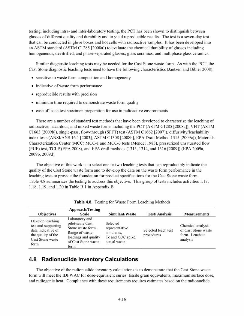
4.16
testing, including intra- and inter-laboratory testing, the PCT has been shown to distinguish between glasses of different quality and durability and to yield reproducible results. The test is a seven-day test that can be conducted in glove boxes and hot cells with radioactive samples. It has been developed into an ASTM standard (ASTM C1285 [2008a]) to evaluate the chemical durability of glasses including homogeneous, devitrified, and phase-separated glasses; glass ceramics; and multiphase glass ceramics.
Similar diagnostic leaching tests may be needed for the Cast Stone waste form. As with the PCT, the Cast Stone diagnostic leaching tests need to have the following characteristics (Jantzen and Bibler 2008):
sensitive to waste form composition and homogeneity
indicative of waste form performance
reproducible results with precision
minimum time required to demonstrate waste form quality
ease of leach test specimen preparation for use in radioactive environments
There are a number of standard test methods that have been developed to characterize the leaching of radioactive, hazardous, and mixed waste forms including the PCT (ASTM C1285 [2008a]), VHT (ASTM C1663 [2009b]), single-pass, flow-through (SPFT) test (ASTM C1662 [2007]), diffusivity/leachability index tests (ANSI/ANS 16.1 [2003], ASTM C1308 [2008b], EPA Draft Method 1315 [2009c]), Materials Characterization Center (MCC) MCC-1 and MCC-3 tests (Mendel 1983), pressurized unsaturated flow (PUF) test, TCLP (EPA 2008), and EPA draft methods (1313, 1314, and 1316 [2009]) (EPA 2009a, 2009b, 2009d).
The objective of this work is to select one or two leaching tests that can reproducibly indicate the quality of the Cast Stone waste form and to develop the data on the waste form performance in the leaching tests to provide the foundation for product specifications for the Cast Stone waste form. Table 4.8 summarizes the testing to address this objective. This group of tests includes activities 1.17, 1.18, 1.19, and 1.20 in Table B.1 in Appendix B.
Table 4.8. Testing for Waste Form Leaching Methods
Objectives
Approach/Testing
Scale Simulant/Waste Test/ Analysis Measurements
Develop leaching test and supporting data indicative of the quality of the Cast Stone waste form
Laboratory and pilot-scale Cast Stone waste form. Range of waste loadings and quality of Cast Stone waste form.
Selected representative simulants, Tc and COC spike, actual waste
Selected leach test procedures
Chemical analysis of Cast Stone waste form. Leachate analysis
4.8 Radionuclide Inventory Calculations
The objective of the radionuclide inventory calculations is to demonstrate that the Cast Stone waste form will meet the IDFWAC for dose-equivalent curies, fissile gram equivalents, maximum surface dose, and radiogenic heat. Compliance with these requirements requires estimates based on the radionuclide
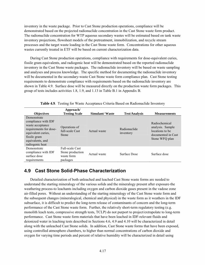
4.17
inventory in the waste package. Prior to Cast Stone production operations, compliance will be demonstrated based on the projected radionuclide concentration in the Cast Stone waste form product. The radionuclide concentration for WTP aqueous secondary wastes will be estimated based on tank waste inventory projections, flowsheet models of the pretreatment, immobilization, and recycle stream processes and the target waste loading in the Cast Stone waste form. Concentrations for other aqueous wastes currently treated in ETF will be based on current characterization data.
During Cast Stone production operations, compliance with requirements for dose-equivalent curies, fissile gram equivalents, and radiogenic heat will be demonstrated based on the reported radionuclide inventory in the Cast Stone waste packages. The radionuclide inventory will be based on waste sampling and analyses and process knowledge. The specific method for documenting the radionuclide inventory will be documented in the secondary-waste Cast Stone waste form compliance plan. Cast Stone testing requirements to demonstrate compliance with requirements based on the radionuclide inventory are shown in Table 4.9. Surface dose will be measured directly on the production waste form packages. This group of tests includes activities 1.8, 1.9, and 1.13 in Table B.1 in Appendix B.
Table 4.9. Testing for Waste Acceptance Criteria Based on Radionuclide Inventory
Objectives
Approach/
Testing Scale Simulant/ Waste Test/Analysis Measurements
Demonstrate compliance with IDF waste acceptance requirements for dose-equivalent curies, fissile gram equivalents, and radiogenic heat
Operations of full-scale Cast Stone
Actual waste Radionuclide inventory
Radiochemical analysis. Sample locations to be documented in Cast Stone WFQ plan
Demonstrate compliance with IDF surface dose requirements
Full-scale Cast Stone production waste form packages
Actual waste Surface Dose Surface dose
4.9 Cast Stone Solid-Phase Characterization
Detailed characterization of both unleached and leached Cast Stone waste forms are needed to understand the starting mineralogy of the various solids and the mineralogy present after exposure-the weathering process-to leachants including oxygen and carbon dioxide gases present in the vadose zone air-filled pores. Without an understanding of the starting mineralogy of the Cast Stone waste form and the subsequent changes (mineralogical, chemical and physical) in the waste form as it weathers in the IDF subsurface, it is difficult to predict the long-term release of contaminants of concern and the long-term performance of the Cast Stone waste form. Further, the relatively short-term regulatory testing (e.g. monolith leach tests, compressive strength tests, TCLP) do not purport to project/extrapolate to long-term performance. Cast Stone waste form materials that have been leached in IDF-relevant fluids and deionized water in leaching tests described in Sections 4.6, 4.9 and 4.10 will be characterized in detail along with the unleached Cast Stone solids. In addition, Cast Stone waste forms that have been exposed, using controlled atmosphere chambers, to higher than normal concentrations of carbon dioxide and oxygen for varying time periods and percent of relative humidity will be characterized in detail using
4.18
methods discussed in Um et al. (2011). The evolution of the mineralogy and physical/chemical properties of the Cast Stone waste form is needed to predict the long-term evolution of the disposed waste form as it weathers (see Table B.1 activity 7.3). Through knowledge of the starting Cast Stone mineralogy and physical/chemical properties and the weathered Cast Stone waste form mineralogy and changed physical/chemical properties, one can develop a combined physical and chemical conceptual model of the weathering process. Of particular interest in supporting the long-term projections of the fate of key contaminants is identification of the solid-phase speciation of 99Tc and 129I (stable iodide, 127I, will be used) in the Cast Stone waste form (see Table B.1 activities 7.1 and 7.2).
The solids characterization of selected samples will include determining
mineralogy using bulk powder X-ray diffraction (XRD) and micro-XRD of selected samples
mineralogy and particle size/shape using SEM and TEM equipped with chemical microprobe energy-dispersive X-ray fluorescence
porosity and pore structure (size distribution and pore throat shapes and sizes) and crack numbers and sizes using X-ray and neutron microtomography, Hg intrusion porosimetry, BET, and SEM
valence state and nearest neighbor atoms determination using synchrotron XAS (X-ray absorption near edge structure [XANES] and extended X-ray absorption fine structure [EXAFS])
redox capacity of individual dry materials and Cast Stone waste form product
specific surface area using N2 and/or Ar gas adsorption (BET)
bulk chemical composition
Brief descriptions of most of these characterization techniques are found in Appendix D.
Classical bulk XRD characterization often is hindered by microcrystalline-sized minerals yielding broad and non-distinct X-ray patterns. Further, bulk XRD generally requires that are 2 or more wt% of a mineral be present to be detected. Therefore, SEM and TEM aid in determining mineralogy via chemical composition and particle shape identification, especially for minerals at low abundance and small particle size. The synchrotron-based XANES techniques can identify the valence state of key redox-sensitive constituents such as 99Tc and 129I present in the solid, and EXAFS can identify molecular-scale information such as coordination number and interatomic distance between atoms. Knowledge of the molecular structure and bonding lengths can aid in determining how strongly the key contaminants are retained in the Cast Stone waste form. Micro-XRD and micro-X-ray fluorescence (XRF) techniques can be used to isolate very small regions or individual particles in mounted samples such that key areas can be located to optimize the XAS characterization efforts on locations with the highest concentrations of the key COCs. Using XRF and SEM mapping techniques, the location and distribution of each contaminant can be determined.
One key effort needed to allow quantitative mineralogy estimates for the Cast Stone product is to generate XRD calibrated spectra from mixtures of known masses standards of the known minerals present. Pure-phase solids of the minerals will either be procured from commercial sources or created using ceramic or hydrothermal synthesis from reagent-grade chemicals. The XRD spectra for the pure-phase minerals and known mixtures will be systematically prepared to allow empirical algorithms (XRD calibration curves) to be developed. The calibration curves will be used to devolve the spectra for the
4.19
Cast Stone product used in the leach testing and the final weathered solid phases to allow quantitative estimates of the mineralogy of unreacted and weathered Cast Stone solids.
The redox capacity of the unleached Cast Stone product will be measured to understand the capacity for the Cast Stone waste form to maintain redox-sensitive elements such as Tc in their less mobile (reduced) states (see Table B.1 activity 7.5). Redox capacity will be measured using two techniques (Lee and Batchelor 2003, Angus and Glasser 1985).
The BET surface area of the unleached crushed and sieved Cast Stone waste form material will also be measured by nitrogen gas absorption (Brunauer et al. 1938). The specific surface areas of the crushed and sieved Cast Stone waste form are required in order to calculate various leaching constants and rates in several of the leach tests described in Section 4.10.
The bulk chemical compositions of the dry materials and the final Cast Stone waste form need to be determined as input to some of the leach tests described below as well as to aid in mineral identification by the various solid-phase characterization techniques. Microwave digestion uses high temperatures and pressures to accelerate the digestion process of solid matrices with strong acids such as nitric, hydrochloric, and hydrofluoric. The use of hydrofluoric acid helps to achieve total dissolution of solid materials (EPA SW-846 Method 3052, Microwave Assisted Acid Digestion of Siliceous and Organically
Based Matrices). The resulting solution is then analyzed by inductively coupled plasma-optical emission spectroscopy (ICP-OES) for major elements such as Al, Ca, Fe, K, Mg, Mn, Na, Ni, P, Pb, S, Si, and Ti and inductively coupled plasma-mass spectroscopy (ICP-MS) for RCRA trace metals, Cs, Re, 99Tc and iodide. When iodide is present, a separate aliquot of the solids needs to be digested using an alkaline fusion as described in Brown et al. (2005). Anion content in the solids is determined from a sodium peroxide/sodium hydroxide fusion at 600°C followed by water dissolution of the fused material (ASTM C1463 [2000]). The resulting water solution is then analyzed by ion chromatography (IC) for NO3
−, F−, and Cl−, SO42− and PO4
3−. The total carbon and inorganic carbon content of the solids is directly measured by a total carbon analyzer using a few hundred mg of crushed solid (e.g., ASTM D4319-93 [2001]). Organic carbon is calculated from the difference between total and inorganic carbon.
Through assimilation of all the solid-phase characterization information and total chemical composition of unleached and leached Cast Stone waste form, one can better identify controlling mechanisms for species release and the mineral weathering sequence of the waste form needed to support long-term performance modeling of the waste form.
4.10 Waste Form Leach Testing—PA Support
The Cast Stone waste form needs to be studied to gain an understanding of the mechanisms that control the release of major constituents as well as the trace contaminants that cause the greatest risk to humans and groundwater. From knowledge of the controlling release mechanisms, one can build either mechanistic (physicochemical) or empirical algorithms that are needed by PA computer codes to generate long-term predictions on the fate of potential contaminants in the waste forms. Examples of the types of mechanistic and empirical algorithms and overall PA process are found in Bacon et al. (2000), Bacon and McGrail (2001), McGrail et al. (2001) and Mann et al. (2001).
The following activities are needed to study the release mechanisms of major and trace contaminant species from the Cast Stone waste form capable of meeting the IDF facility requirements. The main goals
4.20
of the tests are to provide insight into the chemical and mass transport processes that control the weathering, corrosion, or leaching of species from the solid waste forms and monoliths and to provide numerical data on key parameters that feed construction of algorithms used in PA codes used to predict the long-term fate of species within the waste forms/packages. The following subsections focus on describing the types of waste form characterization and tests needed to support risk and long-term performance predictive modeling.
4.10.1 Cast Stone Monolith Leach Testing
There is a proposed IDF waste package acceptance criterion that states that the waste form shall exhibit a sodium leachability index greater than 6.0 when tested in deionized water over a 90-day period using the American National Standards Institute/American Nuclear Society (ANSI/ANS) 16.1 testing procedure (ANSI/ANS 2003). For PA support, such monolith leach testing is performed for longer time periods and often uses more relevant leachants than deionized water. Further, there are at least two other very similar monolith leach test protocols, EPA 1315 (EPA 2009c) and ASTM C1308 (ASTM 2008b), that use the same equipment and basic test protocols with only slight variations in sampling times. The ASTM C1308 procedure has an accompanying computer code, Accelerated Leach Test (ALT) (Furhmann et al. 1990), that aids in data reduction and evaluation as to whether certain diffusion laws are evidenced in the raw data.
These intermittent solution-exchange monolith leach procedures generally are used to determine the apparent diffusion coefficient for specific contaminants out of monolithic waste forms. The test protocols, shown schematically in Figure 4.2, immerse monoliths (generally right circular cylinders) into a volume of leachant (measured in mL) that is 10 times larger than the geometric surface area measured in cm2. At set times, the monolithic waste form is moved to a second container with fresh leachant, and the diffusion leach testing continues. At the next designated time, the waste form is placed back in the first container that now contains fresh leachant. The process of alternating the placement of the monolithic waste form between the two containers continues for the duration of the test. The ANS-16.1 protocol has ten solution exchanges occurring after 2, 7, 24, 48, 72, 96, 120, 456, 1128, and 2160 hours (total of 90 days), but there is no requirement to stop the leach tests after 90 days when collecting data to support long-term PA algorithm development. The concentration of all contaminants of interest in each leachate is measured and used to calculate individual time increment (n) effective diffusion coefficients using Equation 4.1. Often major constituents in the leachates as well as pH and Eh are measured to allow geochemical speciation and saturation index calculations to be performed as an aid to understanding the leach mechanisms that might be controlling the release of specific contaminants out of the monolith.
De(n) = [(an/A0)/tn]2[V/S]2 [T] 4.1
where: De(n) = effective diffusivity coefficient (cm2/s) for leaching interval, tn – tn−1 an = activity or mass of contaminant leached during the leaching interval, tn – tn−1 A0 = total initial activity or mass of contaminant in the waste form monolith an/A0 = fraction of radionuclide leached during interval tn – tn−1 tn = duration of the nth leaching interval tn – tn−1 in s V = volume of specimen, cm3 S = geometric surface area of the specimen, cm2 T = mean leaching time = [1/2(tn + tn−1)]2 in s.
4.21
The leachability index (LI) for each time interval is defined in Equation 4.2 as
LIn = log (/De(n)) 4.2
where = a constant = 1 cm2/s, and De(n) is the effective diffusion coefficient for the contaminant for leach interval n.
An average of the sodium leachability indices for the ten individual ANS 16.1 solution exchanges is calculated as shown in Equation 4.3.
LI90-day = 10]))([log()(
10,1
neD
n
4.3
The EPA 1315 leach protocol (EPA 2009c), quite similar to the ANS-16.1 protocol, has been proposed to replace the ANS-16.1 method by slightly modifying the times at which the leachant solution replacements occur. The method also endorses carrying out the leach tests for time periods beyond 90 days and suggests that leachants other than deionized water be used that are more relevant to the waste form disposal environments. The ASTM C-1308 also recommends using more relevant leachants, various temperatures, and longer time periods to evaluate the appropriateness of relying on diffusion processes to model the raw data.
In support of risk assessment and PA needs, empirical effective diffusivities for key contaminants and major waste constituents will be measured in long-term leach tests using Cast Stone waste form monoliths. The intermittent-solution-exchange leach test will be extended well beyond the 90-day contact time typically used for regulatory purposes, and the two leachants more relevant to IDF, vadose zone pore water and IDF glass leachate, will be used for most tests. The chemical compositions of the latter two leachants are shown in (Table 4.10). After approximately one year of testing, select monoliths will be sectioned and characterized by the solid-phase techniques mentioned in Section 4.9 to understand the types of minerals that occur on the surface and within the weathering monolith. A pH and redox capacity profile from the outer edge to the interior of the monolith being characterized will be measured using a phenolpthalein indicator (Powers 2005) and the redox capacity methods (Lee and Batchelor 2003; Angus and Glasser 1985). These profiles will aid in understanding the pH buffering caused by carbon dioxide ingress and the oxidation caused by oxygen ingress. Both processes must be considered when estimating long-term performance of the waste forms disposed of in the IDF.
Other monolith leach tests will be continued beyond the one-year contact period as long as practical to continue collecting contaminant release data for longer time periods. Once leach testing is completed, similar solid-phase characterization and pH and Eh depth profiles will be performed, if found to be useful, to identify the minerals formed during the weathering process and the release mechanisms, and to quantify the effective diffusion of contaminants out of and reactants (e.g., oxygen and carbonate) into the monoliths. The tests and characterization described in this subsection will generate the necessary information and data to address issues 9.1 and 9.2 in Table B.1.
In a similar fashion Cast Stone waste form monoliths that have been weathered under accelerated atmospheres of carbon dioxide and oxygen will be leach tested to evaluate whether the release of key contaminants is changed after accelerated weathering.
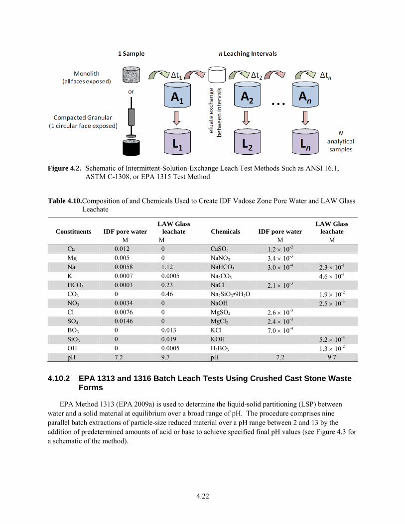
4.22
Figure 4.2. Schematic of Intermittent-Solution-Exchange Leach Test Methods Such as ANSI 16.1,
ASTM C-1308, or EPA 1315 Test Method
Table 4.10. Composition of and Chemicals Used to Create IDF Vadose Zone Pore Water and LAW Glass Leachate
Constituents IDF pore water
LAW Glass
leachate Chemicals IDF pore water
LAW Glass
leachate
M M M M Ca 0.012 0 CaSO4 1.2 10-2 Mg 0.005 0 NaNO3 3.4 10-3 Na 0.0058 1.12 NaHCO3 3.0 10-4 2.3 10-1 K 0.0007 0.0005 Na2CO3 4.6 10-1 HCO3 0.0003 0.23 NaCl 2.1 10-3 CO3 0 0.46 Na2SiO3•9H2O 1.9 10-2 NO3 0.0034 0 NaOH 2.5 10-3 Cl 0.0076 0 MgSO4 2.6 10-3 SO4 0.0146 0 MgCl2 2.4 10-3 BO3 0 0.013 KCl 7.0 10-4 SiO3 0 0.019 KOH 5.2 10-4 OH 0 0.0005 H3BO3 1.3 10-2 pH 7.2 9.7 pH 7.2 9.7
4.10.2 EPA 1313 and 1316 Batch Leach Tests Using Crushed Cast Stone Waste Forms
EPA Method 1313 (EPA 2009a) is used to determine the liquid-solid partitioning (LSP) between water and a solid material at equilibrium over a broad range of pH. The procedure comprises nine parallel batch extractions of particle-size reduced material over a pH range between 2 and 13 by the addition of predetermined amounts of acid or base to achieve specified final pH values (see Figure 4.3 for a schematic of the method).
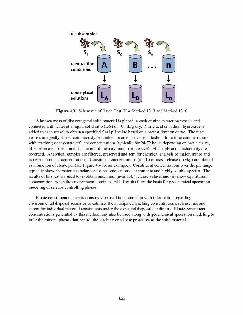
4.23
Figure 4.3. Schematic of Batch Test EPA Method 1313 and Method 1316
A known mass of disaggregated solid material is placed in each of nine extraction vessels and contacted with water at a liquid-solid ratio (L/S) of 10 mL/g-dry. Nitric acid or sodium hydroxide is added to each vessel to obtain a specified final pH value based on a pretest titration curve. The nine vessels are gently stirred continuously or tumbled in an end-over-end fashion for a time commensurate with reaching steady-state effluent concentrations (typically for 24-72 hours depending on particle size, often estimated based on diffusion out of the maximum particle size). Eluate pH and conductivity are recorded. Analytical samples are filtered, preserved and sent for chemical analysis of major, minor and trace contaminant concentrations. Constituent concentrations (mg/L) or mass release (mg/kg) are plotted as a function of eluate pH (see Figure 4.4 for an example). Constituent concentrations over the pH range typically show characteristic behavior for cationic, anionic, oxyanionic and highly soluble species. The results of this test are used to (i) obtain maximum (available) release values, and (ii) show equilibrium concentrations when the environment dominates pH. Results form the basis for geochemical speciation modeling of release-controlling phases.
Eluate constituent concentrations may be used in conjunction with information regarding environmental disposal scenarios to estimate the anticipated leaching concentrations, release rate and extent for individual material constituents under the expected disposal conditions. Eluate constituent concentrations generated by this method may also be used along with geochemical speciation modeling to infer the mineral phases that control the leaching or release processes of the solid material.
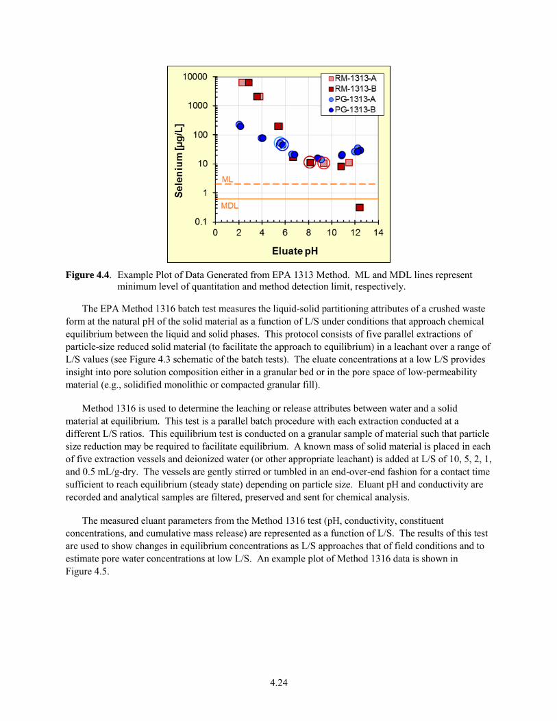
4.24
Figure 4.4. Example Plot of Data Generated from EPA 1313 Method. ML and MDL lines represent
minimum level of quantitation and method detection limit, respectively.
The EPA Method 1316 batch test measures the liquid-solid partitioning attributes of a crushed waste form at the natural pH of the solid material as a function of L/S under conditions that approach chemical equilibrium between the liquid and solid phases. This protocol consists of five parallel extractions of particle-size reduced solid material (to facilitate the approach to equilibrium) in a leachant over a range of L/S values (see Figure 4.3 schematic of the batch tests). The eluate concentrations at a low L/S provides insight into pore solution composition either in a granular bed or in the pore space of low-permeability material (e.g., solidified monolithic or compacted granular fill).
Method 1316 is used to determine the leaching or release attributes between water and a solid material at equilibrium. This test is a parallel batch procedure with each extraction conducted at a different L/S ratios. This equilibrium test is conducted on a granular sample of material such that particle size reduction may be required to facilitate equilibrium. A known mass of solid material is placed in each of five extraction vessels and deionized water (or other appropriate leachant) is added at L/S of 10, 5, 2, 1, and 0.5 mL/g-dry. The vessels are gently stirred or tumbled in an end-over-end fashion for a contact time sufficient to reach equilibrium (steady state) depending on particle size. Eluant pH and conductivity are recorded and analytical samples are filtered, preserved and sent for chemical analysis.
The measured eluant parameters from the Method 1316 test (pH, conductivity, constituent concentrations, and cumulative mass release) are represented as a function of L/S. The results of this test are used to show changes in equilibrium concentrations as L/S approaches that of field conditions and to estimate pore water concentrations at low L/S. An example plot of Method 1316 data is shown in Figure 4.5.
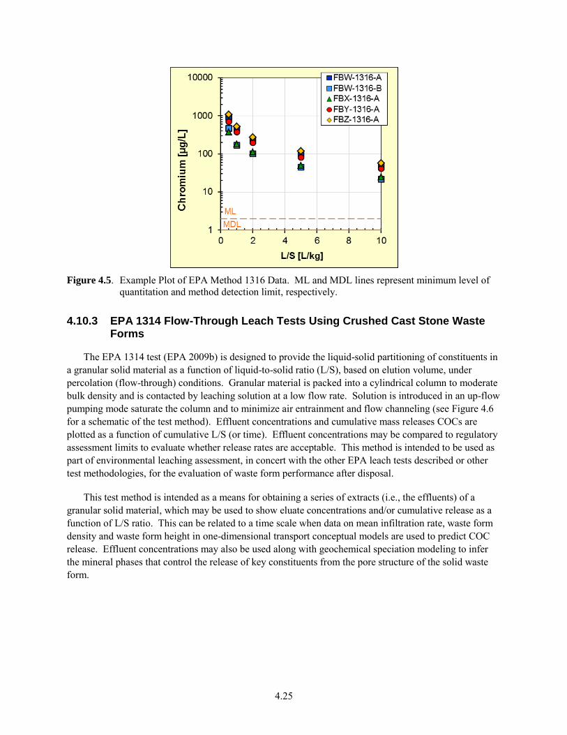
4.25
Figure 4.5. Example Plot of EPA Method 1316 Data. ML and MDL lines represent minimum level of
quantitation and method detection limit, respectively.
4.10.3 EPA 1314 Flow-Through Leach Tests Using Crushed Cast Stone Waste Forms
The EPA 1314 test (EPA 2009b) is designed to provide the liquid-solid partitioning of constituents in a granular solid material as a function of liquid-to-solid ratio (L/S), based on elution volume, under percolation (flow-through) conditions. Granular material is packed into a cylindrical column to moderate bulk density and is contacted by leaching solution at a low flow rate. Solution is introduced in an up-flow pumping mode saturate the column and to minimize air entrainment and flow channeling (see Figure 4.6 for a schematic of the test method). Effluent concentrations and cumulative mass releases COCs are plotted as a function of cumulative L/S (or time). Effluent concentrations may be compared to regulatory assessment limits to evaluate whether release rates are acceptable. This method is intended to be used as part of environmental leaching assessment, in concert with the other EPA leach tests described or other test methodologies, for the evaluation of waste form performance after disposal.
This test method is intended as a means for obtaining a series of extracts (i.e., the effluents) of a granular solid material, which may be used to show eluate concentrations and/or cumulative release as a function of L/S ratio. This can be related to a time scale when data on mean infiltration rate, waste form density and waste form height in one-dimensional transport conceptual models are used to predict COC release. Effluent concentrations may also be used along with geochemical speciation modeling to infer the mineral phases that control the release of key constituents from the pore structure of the solid waste form.
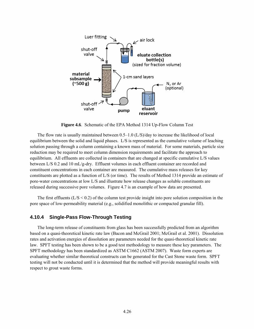
4.26
Figure 4.6. Schematic of the EPA Method 1314 Up-Flow Column Test
The flow rate is usually maintained between 0.5–1.0 (L/S)/day to increase the likelihood of local equilibrium between the solid and liquid phases. L/S is represented as the cumulative volume of leaching solution passing through a column containing a known mass of material. For some materials, particle size reduction may be required to meet column dimension requirements and facilitate the approach to equilibrium. All effluents are collected in containers that are changed at specific cumulative L/S values between L/S 0.2 and 10 mL/g-dry. Effluent volumes in each effluent container are recorded and constituent concentrations in each container are measured. The cumulative mass releases for key constituents are plotted as a function of L/S (or time). The results of Method 1314 provide an estimate of pore-water concentrations at low L/S and illustrate how release changes as soluble constituents are released during successive pore volumes. Figure 4.7 is an example of how data are presented.
The first effluents (L/S < 0.2) of the column test provide insight into pore solution composition in the pore space of low-permeability material (e.g., solidified monolithic or compacted granular fill).
4.10.4 Single-Pass Flow-Through Testing
The long-term release of constituents from glass has been successfully predicted from an algorithm based on a quasi-theoretical kinetic rate law (Bacon and McGrail 2001; McGrail et al. 2001). Dissolution rates and activation energies of dissolution are parameters needed for the quasi-theoretical kinetic rate law. SPFT testing has been shown to be a good test methodology to measure these key parameters. The SPFT methodology has been standardized as ASTM C1662 (ASTM 2007). Waste form experts are evaluating whether similar theoretical constructs can be generated for the Cast Stone waste form. SPFT testing will not be conducted until it is determined that the method will provide meaningful results with respect to grout waste forms.
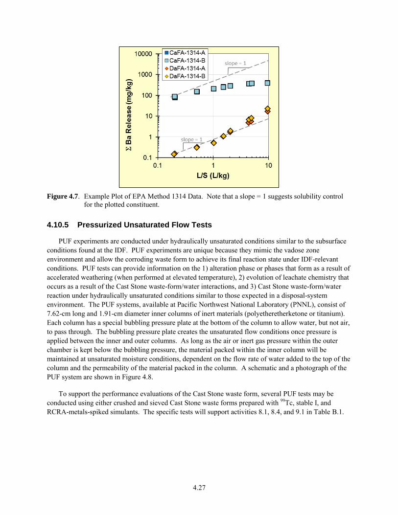
4.27
Figure 4.7. Example Plot of EPA Method 1314 Data. Note that a slope = 1 suggests solubility control
for the plotted constituent.
4.10.5 Pressurized Unsaturated Flow Tests
PUF experiments are conducted under hydraulically unsaturated conditions similar to the subsurface conditions found at the IDF. PUF experiments are unique because they mimic the vadose zone environment and allow the corroding waste form to achieve its final reaction state under IDF-relevant conditions. PUF tests can provide information on the 1) alteration phase or phases that form as a result of accelerated weathering (when performed at elevated temperature), 2) evolution of leachate chemistry that occurs as a result of the Cast Stone waste-form/water interactions, and 3) Cast Stone waste-form/water reaction under hydraulically unsaturated conditions similar to those expected in a disposal-system environment. The PUF systems, available at Pacific Northwest National Laboratory (PNNL), consist of 7.62-cm long and 1.91-cm diameter inner columns of inert materials (polyetheretherketone or titanium). Each column has a special bubbling pressure plate at the bottom of the column to allow water, but not air, to pass through. The bubbling pressure plate creates the unsaturated flow conditions once pressure is applied between the inner and outer columns. As long as the air or inert gas pressure within the outer chamber is kept below the bubbling pressure, the material packed within the inner column will be maintained at unsaturated moisture conditions, dependent on the flow rate of water added to the top of the column and the permeability of the material packed in the column. A schematic and a photograph of the PUF system are shown in Figure 4.8.
To support the performance evaluations of the Cast Stone waste form, several PUF tests may be conducted using either crushed and sieved Cast Stone waste forms prepared with 99Tc, stable I, and RCRA-metals-spiked simulants. The specific tests will support activities 8.1, 8.4, and 9.1 in Table B.1.
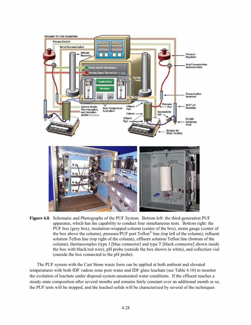
4.28
Figure 4.8. Schematic and Photographs of the PUF System. Bottom left: the third-generation PUF
apparatus, which has the capability to conduct four simultaneous tests. Bottom right: the PUF box (grey box), insulation-wrapped column (center of the box), strain gauge (center of the box above the column), pressure/PUF port Teflon® line (top left of the column), influent solution Teflon line (top right of the column), effluent solution Teflon line (bottom of the column), thermocouples (type J [blue connector] and type T [black connector] shown inside the box with black/red wire), pH probe (outside the box shown in white), and collection vial (outside the box connected to the pH probe).
The PUF system with the Cast Stone waste form can be applied at both ambient and elevated temperatures with both IDF vadose zone pore water and IDF glass leachate (see Table 4.10) to monitor the evolution of leachate under disposal-system unsaturated water conditions. If the effluent reaches a steady-state composition after several months and remains fairly constant over an additional month or so, the PUF tests will be stopped, and the leached solids will be characterized by several of the techniques
4.29
listed in Section 4.9 to identify the types and amounts of secondary minerals formed by weathering under unsaturated conditions. If the leachate chemical composition does not reach a steady state, PUF tests will be continued as long as feasible with a few terminated at set times to provide information on the amounts and types of secondary minerals that form during the weathering process. It may be possible to evaluate the weathering kinetics of Cast Stone weathering from PUF tests run at various temperatures.
4.11 Waste Package Release Testing
No full-scale waste package release tests are planned to be performed on the Cast Stone waste form within its metal container. Future PAs are not expected to take credit for container properties in minimizing contaminant releases, based on much slow release from the Cast Stone matrix and based on previous PA treatments of the containers’ role in long term release. However, some tests used to study the Cast Stone waste form to support the development of the release model needed in the systems PA code will include higher concentrations of ferrous iron and low redox conditions to quantify the impacts of corroding iron containers on mass transport out of the low-permeability Cast Stone monolith. This will allow the effects of the metal container and its corrosion products (e.g. iron oxides) on the leach rates of constituents from the Cast Stone waste form and re-adsorption of constituents onto the corrosion products to be estimated (see activity 9.1 in Table B.1).
Depending on the container selected, it may be necessary to investigate waste form/container interactions that could lead to premature degradation of the container. Another scenario would be the impacts of co-disposal of LAW glass and its leachates on the Cast Stone container’s outer surface corrosion.
4.12 Waste Form Release Model
Quantifying the rate and extent of element or contaminant release from pure minerals, glasses, mixtures of minerals and amorphous solids, such as the Cast Stone waste form, has been a challenge to predictive geochemistry modeling for decades. The early geochemistry studies relevant to creating release models of solids similar to nuclear waste forms have focused on understanding the weathering of primary minerals and basaltic glasses contained in the earth’s crust. Theories related to mineral and glass weathering developed within the geochemistry community, such as Transition State Theory of Chemical Kinetics (e.g., Lasaga 1998), have been used to predict the release of contaminants from nuclear waste forms and other engineered materials. The weathering of these materials is impacted by a series of sequential and/or simultaneous competing chemical and physical reactions/processes that control the mass transfer of contaminants from the waste form into solution. These reaction/processes include, but are not limited to, the following:
diffusion/advection
dissolution/precipitation
adsorption/absorption/desorption
complexation and ion exchange
oxidation/reduction
paragenetic mineral transformations.
4.30
The overall impact of individual or coupled reactions/processes on the long-term performance of the Cast Stone waste form will depend on a number of different variables, such as composition, the resistance of materials to physical and chemical degradation, the dominant mechanism controlling contaminant release, and the disposal-system environment. Therefore, performance testing must focus on the use of experiments that provide model parameters that explain the key processes and in some cases accelerate the weathering process to obtain the data needed to predict performance in a realistic time frame. The results produced from the laboratory-scale testing and experiments discussed in this test plan will be used to provide the parameters needed to predict performance and contaminant release over ~10,000 years, which is the expected period of performance needed for the IDF engineered system and the Hanford subsurface natural environment.
Performance testing must address the following issues:
Identify the key reactions and/or processes affecting waste form durability and contaminant release.
Quantify the extent and rate of these reactions and/or processes.
Obtain the model parameters needed to describe these reactions and/or processes and predict the behavior of the system.
Verify the derived model parameters.
The future enhanced source-term algorithm for Cast Stone is currently being evaluated with two different software suites being considered. One software suite was developed by Bacon and McGrail (2005) and Freedman et al. (2007). This suite of codes has been chosen for glass waste forms and may be applicable for Cast Stone if the following key additions/improvements are developed:
The release rates of the major components for each identifiable Cast Stone solid phase will be included (unless certain ones are found to be unimportant).
Updated thermodynamic data for the pure end-member and/or idealized solid-solution mineral phases that constitute Cast Stone will be either directly measured or estimated.
Common ion effects (Al, Si, Ca, and perhaps other species) obtained in preliminary leach experiments (perhaps using the SPFT method) will be explicitly incorporated in the Cast Stone waste form/waste package release model(s).
Mass transport properties/limitations (including physical changes to pore structures caused by cracks, carbonation, and other secondary mineral diagenesis) measured on Cast Stone waste form monoliths will be explicitly incorporated in the waste form/waste package release model(s).
Partitioning of 99Tc, 129I, and key RCRA metals among the Cast Stone freshly cured phases and the evolution as the Cast Stone continues to cure and weather will be explicitly incorporated in the waste form/waste package release model(s). Either mechanistically based or empirically based paragenetic reaction networks (i.e., element-specific release algorithms) for each of the key COCs will also be explicitly incorporated in the waste form/waste package release model(s).
The second software suite is tailored for cementitious waste forms such as Cast Stone and has been constructed by a consortium of organizations under a partnership named Cementitious Barriers Partnership (CBP) (see <http://cementbarriers.org/about/> for details). The CBP currently is constructing a linked suite (integrated framework) of computer codes that are state-of-the-art phenomenological tools
4.31
that describe the performance of cementitious waste forms and engineered barriers. These software codes require a significant amount of physical and chemical data as input, may involve a detailed computational grid as part of the solution, and describe a specific behavior of the cementitious entity (see Section 4.14 for additional details). Current and planned CBP software will offer:
a capability to predict physical and chemical properties of cementitious materials through time, and
the transport/leaching of contaminant species from cementitious waste forms and through concrete barriers.
Regardless of which suite of codes is chosen to model the long-term fate of contaminants for the Cast Stone waste form, the process for developing the improved waste form release model relies on the laboratory testing discussed in this testing plan to quantify the needed parameters used in the numerical predictive long-term PA models to simulate the key reactions and/or processes affecting release over long time frames. The technical defensibility of the release model is bolstered by showing allegiance to or similarity between the numerical release algorithms and basic thermodynamic and kinetic theories. A key tenet of supporting the technical defensibility of the process is reliance on determining the chemical durability of relevant pure-phase minerals. To accurately model the release of the key risk driver contaminants that may segregate into specific solid phases within the Cast Stone waste form, an understanding of dissolution kinetics of each dominant solid phase (be it mineral or a solid solution) is needed. Therefore, testing will evaluate the efficacy of using the forward rate of dissolution parameters as measured with the SPFT test method using both key cementitious individual phases and the bulk Cast Stone. Preliminary tests will be conducted as a function of pH, temperature, and solution composition on the bulk Cast Stone as well as a few key individual cementitious minerals to evaluate whether this approach is generating useful data. The predictability of the dissolution process of both the bulk Cast Stone and its key individual minerals will be compared with predictions from the selected code suite.
Basic thermodynamic properties of each pure reference phase will be found in the literature or experimentally determined if not available in the literature. For example, the solubility constant (Ksp) or Gibbs free energy of reaction for the dissolution of each reference phase may not be available. Solubility tests such as described in Yang and Steefel (2008) can be conveniently performed using the SPFT apparatus with stop-flow periods. Other basic thermodynamic parameters, such as heat capacity (∆cp), may need to be measured on some of the reference mineral phases to allow the enthalpy to be determined. Then using the van’t Hoff equation (see for example http://cube.case.edu/emac351/c9l3_hand.pdf), the solubility or log K at various temperatures can be calculated. Heat capacity measurements are performed using calorimetry, generally with a constant-pressure calorimeter.
4.13 Batch Adsorption Tests
Once contaminants leach from the waste package, they migrate with the leachate through the rest of the IDF subsurface components in the disposal system and Hanford sediments disturbed by construction activities. Currently the IDF PA, similar to most other repository PAs, does not give any credit to favorable interactions (e.g., adsorption) of the dissolved contaminants with materials, such as metallic container corrosion products, and degraded liners. The reason that metal container corrosion products, degraded liners, etc. are ignored is that they represent a very small mass compared to the waste packages themselves. Thus, their ability to either favorably or deleteriously affect the fate of dissolved contaminants has been deemed to be insignificant. Recent work in Europe related to the long-term
4.32
performance of waste buried in deep repositories includes the interactions of dissolved contaminants from waste packages with the container corrosion products, backfill materials (often clays), and structural concrete used in the tunnels and vaults (De Windt et al. 2006; Grambow and Giffaut 2006; Van Iseghem Iseghem et al. 2006; Mitsui et al. 2009). This literature on multicomponent impacts on waste form performance will be monitored to determine whether there are any significant differences in performance predictions when including such interactions in near-field release models versus the long-term predictions of contaminant fate in the current more simplistic PA conceptual models. Any significant differences in overall system performance discovered in the more detailed and inclusive near-field fate and transport modeling will need to be considered for future improvements in IDF PA models.
Another assumption used in the supplemental waste risk assessment (Mann et al. 2003) was that the co-disposed waste forms (LAW glass, Cast Stone, Fluidized Bed Steam Reforming (FBSR), and Bulk Vitrification) were separated in the IDF trenches by sufficient distances that the leachates from each did not mix with or affect each other within the near field. This simplification will be kept in mind when performing future PA predictions for the current effort where LAW glass and Cast Stone waste form will be co-disposed in the first IDF trench. Some of the proposed leach testing on the Cast Stone waste form will be performed using a simulated LAW glass leachate such that information will be available early in the contaminant-release data-collection process to assess whether the presence of the two waste forms in the same trench leads to deleterious or favorable interactions.
Until new information indicates otherwise, it will be assumed that LAW Cast Stone waste package leachates that migrate beyond the IDF-influenced “near-field” and reach the “far-field” will only interact with Hanford formation vadose zone sediments and aquifer sediments. The key far-field interaction considered is contaminant adsorption-desorption processes, although leachate pH buffering reactions with the sediment could induce some selected precipitation of contaminants or dissolution of additional major components from the Hanford sediments. Such pH-induced precipitation-dissolution reactions are already accommodated in simple reactions between the leachates and the model pure-phase minerals used to represent the near-field Hanford formation sediments surrounding the waste forms in the STOMP code. Therefore, the more significant need is to develop empirical adsorption parameters as well as surface complexation formation constants for the key contaminants in Cast Stone waste form leachates with both the near-field and far-field Hanford sediments for incorporation in transport algorithms.
4.13.1 Batch Adsorption Tests
The simple construct of the partitioning coefficient, Kd, will continue to be used in the next generation IDF PA conceptual model. The first tests will be simple batch Kd adsorption tests using Cast Stone waste form leachates or simulants based on the actual leachates from the various leach tests described in Sections 4.10 and 4.11 that have been spiked with additional concentrations of contaminants, if needed (because of concentrations that are low or below the detection limit), to allow contaminant-specific Kd values to be determined. Care will be taken to make sure that spike concentrations are stable and do not promote contaminant precipitation, which would inflate the calculated Kd value (see Relyea et al. 1980, ASTM D4319-93 [ASTM 2001], or EPA 1999) for details on how to properly conduct batch Kd tests. In addition the batch Kd tests will be performed in a systematic fashion that allows surface complexation models (SCM) to be developed that explicitly accommodate the effects of varying pH and macro constituent concentrations so that more sophisticated adsorption numerical models could be used. The proposed batch Kd tests will provide the necessary data to support activity 12.1 in Table B.1.
4.33
4.13.2 Saturated and Unsaturated Column Tests on Cast Stone Waste Form Solids Embedded in Sediments
Traditionally, risk assessment and PA codes rely solely on site-specific batch Kd tests to obtain necessary sorption values and often also make “worst case” predictions that assume there is no adsorption of key COCs from the waste package leachates (e.g., Mann et al. 2001 and 2003). Should the batch Kd test results for some specific contaminants show difficulties in quantification (such as very low sorption generally found for 99Tc and 129I) and if the preliminary IDF system PA predictions show that the adsorption of contaminants from the waste package leachates is a key process needed to show compliance with risk criteria, then laboratory-scale flow-through columns, under both saturated and unsaturated flow conditions, are proposed. Flow-through column tests are the most accurate method of determining Kd
values for contaminants that exhibit low adsorption. If the above situations prevail and flow-through tests are performed, the flow-through column tests would use both small monoliths and crushed and sieved Cast Stone waste form specimens that are sandwiched within Hanford formation sediment. The leachant that would be percolated through the packed columns would be the simulated vadose zone pore water in some cases and simulated LAW glass leachate in other tests. These tests allow the combined leaching and contaminant adsorption on sediment and transport processes to be conveniently studied. The effluent from the columns is monitored as a function of time or pore volume displaced, and the retardation factor (ratio of the velocity of the water flow to contaminant flow) is determined. The retardation factor can be converted to a Kd value with knowledge of the packed column’s water content, bulk density, and porosity. The retardation factor can be used as direct input to most transport codes to represent the entire suite of chemical reactions between the Cast Stone and the leachants and sediments.
These column tests allow sensitive measurement of the sorption tendencies of poorly sorbing contaminants such as 99Tc and 129I when compared with batch tests that rely on finding an appreciable difference in solution concentration before and after contact with the sediment. For poorly sorbing species, the small difference in concentrations before and after sediment contact leads to poor reproducibility in batch Kd measurements.
In addition, these types of packed-column experiments are useful alternatives to using the costly specialized PUF system described in Section 4.10.5. Because the PUF system often experiences colloid plugging problems where the effluent flow through the bubbling plate frit either slows or completely stops over time, these simpler flow-through column tests could be used to perform many of the Cast Stone waste form proposed leach tests (with or without the presence of the sediment). However, the Wierenga-style unsaturated column (Wierenga et al. 1993, Horton et al. 1982; http://www.soilmeasurement.com/column.html) devices also use bubbling pressure plates for exactly the same reasons as the PUF system to maintain unsaturated moisture conditions. So the colloid plugging problem could occur in them as well. The Wierenga-style unsaturated column devices are also less suited for higher temperature experiments that are often used in the PUF system to accelerate chemical reactions (weathering). Thus some decisions will be made as to which methodologies—PUF vs. more traditional flow-through packed columns—are most cost effective after preliminary data becomes available on Cast Stone waste form performance and preliminary risk assessment and PA predictions indicate which parameters require more data collection. A third option is to use a hanging water column flow through column system to study the “wetter” portion of water saturation conditions in the Hanford Site vadose zone (Dane and Hopmans 2007).
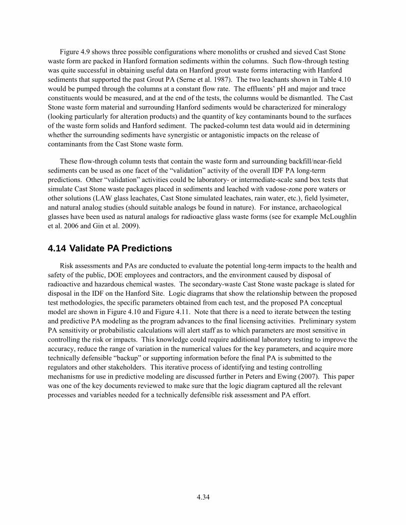
4.34
Figure 4.9 shows three possible configurations where monoliths or crushed and sieved Cast Stone waste form are packed in Hanford formation sediments within the columns. Such flow-through testing was quite successful in obtaining useful data on Hanford grout waste forms interacting with Hanford sediments that supported the past Grout PA (Serne et al. 1987). The two leachants shown in Table 4.10 would be pumped through the columns at a constant flow rate. The effluents’ pH and major and trace constituents would be measured, and at the end of the tests, the columns would be dismantled. The Cast Stone waste form material and surrounding Hanford sediments would be characterized for mineralogy (looking particularly for alteration products) and the quantity of key contaminants bound to the surfaces of the waste form solids and Hanford sediment. The packed-column test data would aid in determining whether the surrounding sediments have synergistic or antagonistic impacts on the release of contaminants from the Cast Stone waste form.
These flow-through column tests that contain the waste form and surrounding backfill/near-field sediments can be used as one facet of the “validation” activity of the overall IDF PA long-term predictions. Other “validation” activities could be laboratory- or intermediate-scale sand box tests that simulate Cast Stone waste packages placed in sediments and leached with vadose-zone pore waters or other solutions (LAW glass leachates, Cast Stone simulated leachates, rain water, etc.), field lysimeter, and natural analog studies (should suitable analogs be found in nature). For instance, archaeological glasses have been used as natural analogs for radioactive glass waste forms (see for example McLoughlin et al. 2006 and Gin et al. 2009).
4.14 Validate PA Predictions
Risk assessments and PAs are conducted to evaluate the potential long-term impacts to the health and safety of the public, DOE employees and contractors, and the environment caused by disposal of radioactive and hazardous chemical wastes. The secondary-waste Cast Stone waste package is slated for disposal in the IDF on the Hanford Site. Logic diagrams that show the relationship between the proposed test methodologies, the specific parameters obtained from each test, and the proposed PA conceptual model are shown in Figure 4.10 and Figure 4.11. Note that there is a need to iterate between the testing and predictive PA modeling as the program advances to the final licensing activities. Preliminary system PA sensitivity or probabilistic calculations will alert staff as to which parameters are most sensitive in controlling the risk or impacts. This knowledge could require additional laboratory testing to improve the accuracy, reduce the range of variation in the numerical values for the key parameters, and acquire more technically defensible “backup” or supporting information before the final PA is submitted to the regulators and other stakeholders. This iterative process of identifying and testing controlling mechanisms for use in predictive modeling are discussed further in Peters and Ewing (2007). This paper was one of the key documents reviewed to make sure that the logic diagram captured all the relevant processes and variables needed for a technically defensible risk assessment and PA effort.
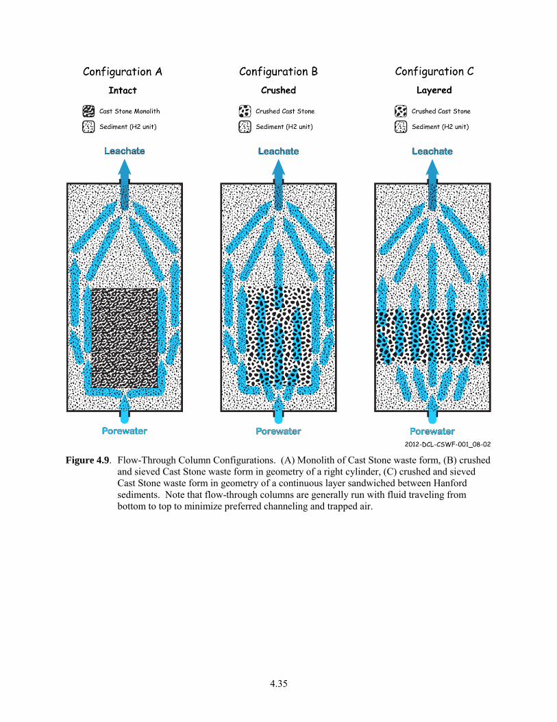
4.35
Figure 4.9. Flow-Through Column Configurations. (A) Monolith of Cast Stone waste form, (B) crushed
and sieved Cast Stone waste form in geometry of a right cylinder, (C) crushed and sieved Cast Stone waste form in geometry of a continuous layer sandwiched between Hanford sediments. Note that flow-through columns are generally run with fluid traveling from bottom to top to minimize preferred channeling and trapped air.
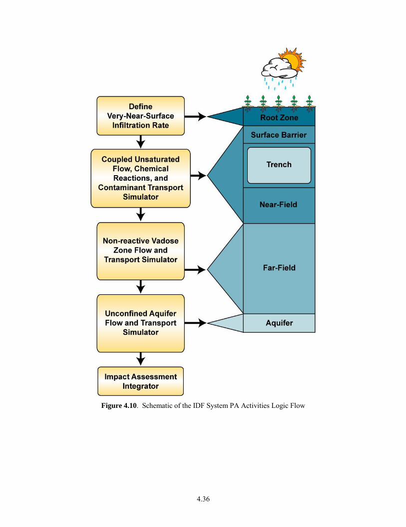
4.36
Figure 4.10. Schematic of the IDF System PA Activities Logic Flow
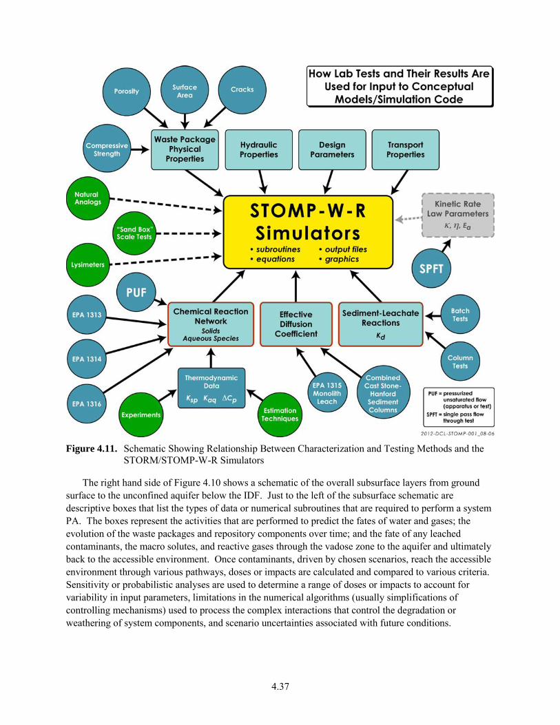
4.37
Figure 4.11. Schematic Showing Relationship Between Characterization and Testing Methods and the
STORM/STOMP-W-R Simulators
The right hand side of Figure 4.10 shows a schematic of the overall subsurface layers from ground surface to the unconfined aquifer below the IDF. Just to the left of the subsurface schematic are descriptive boxes that list the types of data or numerical subroutines that are required to perform a system PA. The boxes represent the activities that are performed to predict the fates of water and gases; the evolution of the waste packages and repository components over time; and the fate of any leached contaminants, the macro solutes, and reactive gases through the vadose zone to the aquifer and ultimately back to the accessible environment. Once contaminants, driven by chosen scenarios, reach the accessible environment through various pathways, doses or impacts are calculated and compared to various criteria. Sensitivity or probabilistic analyses are used to determine a range of doses or impacts to account for variability in input parameters, limitations in the numerical algorithms (usually simplifications of controlling mechanisms) used to process the complex interactions that control the degradation or weathering of system components, and scenario uncertainties associated with future conditions.
4.38
4.14.1 Reactive Transport Simulators for the Waste Form Calculations
The main focus of the testing described in this test plan fits into the second descriptive box in Figure 4.10 labeled Coupled, Unsaturated Flow, Chemical Reactions, and Contaminant Transport Simulator. The following subsections on PA codes are one example of how a detailed technically robust PA could be generated. Other codes and approaches exist and should be vetted by the Secondary Waste project team early in the project’s life so that close co-ordination between the data collectors and the PA modelers can be established. Historically, the IDF system PA has used the Subsurface Transport Over Reactive Multiphases (STORM) code (Bacon et al. 2000, 2004) to perform the calculations of radionuclide releases from the glass. STORM was developed by coupling STOMP, a nonisothermal multiphase flow simulator (White and Oostrom 2006), with AREST-CT Version 1.1, a reactive transport and porous medium alteration simulator (Chen et al. 1995, 1997). STORM represented subsurface flow and transport as a set of coupled, nonlinear, partial differential equations. The equations describe the rate of change of pore-water solute concentrations in variably water-unsaturated, nonisothermal porous media. STORM capabilities include kinetic dissolution of glass (or other waste forms), kinetically controlled precipitation and dissolution of secondary phases, equilibrium aqueous solutes speciation, gas-aqueous equilibria, two-phase flow (water and air), and dynamic updates to porosity and permeability as changes in mineral volumes occur. Most importantly, STORM simulates the waste form dissolution kinetic reaction in which equilibrium depends on only silica and aluminum. Reactive transport in STORM is coupled with unsaturated flow; the unsaturated flow field may be altered by mineral dissolution and precipitation reactions. STORM can also run efficiently in parallel on multi-core workstations and supercomputers, shortening execution times.
However, the STORM simulator limits reactive transport to two dimensions and cannot simulate three-dimensional flow and transport resulting from heterogeneities in the subsurface. Moreover, STORM is no longer under active development and has not received a Class C Safety and Hazard Analysis and Design Software classification. Therefore, under DOE Order 414.1C (DOE 2005), STORM cannot be used for future risk and PA analyses. More details on STORM can be found in Bacon et al. (2000, 2004), Bacon and McGrail (2001), McGrail et al. (2001), and Mann et al. (2001, 2003).
For reasons of continuity with past IDF PA activities, the new version of STORM, STOMP-W-R as described below, is one logical choice for performing future long-term IDF performance predictions. STOMP (White and Oostrom, 2000, 2006) can simulate flow and reactive transport in three dimensions, and adheres to rigorous quality assurance (QA) procedures that are compliant with DOE Order 414.1C, STOMP was updated with the waste form release calculations in fiscal year 2011 (report citation 2011). STOMP is a general purpose simulator that was developed at PNNL for modeling subsurface flow and transport under variably saturated conditions. The simulator uses a variable source code configuration that allows the execution memory and speed to be tailored to the problem specifics. Quantitative predictions from the STOMP simulator are generated from the numerical solution of partial differential equations that describe subsurface environment transport phenomena. Governing equations for solute mass conservation are solved sequentially, following the solution of the coupled flow equations. The ECKEChem (Equilibrium-Conservation-Kinetic Equation Chemistry) module (White and McGrail 2005) is used to simulate reactive geochemistry. Using the variable source code configuration of STOMP, simulations for the IDF PA use an executable designated as STOMP-W-R, which simulates the governing equations for flow, solute transport and reactive geochemistry.
4.39
STOMP development is managed under a Configuration Management Plan (CMP) in conjunction with a Software Test Plan (STP), that detail the procedures used to test, document and archive modifications to the source code. Formal procedures for software problem reporting and corrective actions for software errors and updates are maintained and rigorously implemented. Documentation of all verification and validation testing is publicly available.
Work is currently underway to update eSTOMP, the highly-scalable (parallel) version of STOMP, with the same waste form calculations that have already been incorporated into STOMP. The eSTOMP simulator was developed from STOMP using a component based approach. The key features of this conversion were 1) the definition of a data model to describe a grid that is distributed over multiple processors, 2) the definition of a grid component interface based on this model, and 3) the implementation of the grid component and the conversion of the remaining portions of the code using the Global Arrays toolkit (GA) (Nieplocha et al., 2006). The GA toolkit supports a one-sided communication, shared memory style programming model on both shared and distributed memory platforms. Because the eSTOMP simulator is highly scalable, it is ideally suited for running waste form calculations since long run times can result when they are executed with a serial code. However, the eSTOMP simulator still requires additional documentation and testing to bring it into NQA-1 compliance for Safety Software.
4.14.2 Model Inputs
Figure 4.11 is a schematic showing the relationship between various types of parameter property inputs and specific waste form and waste package leach tests needed for subsurface simulation. The solid-phase characterization activities and waste form and waste package tests described in Sections 4.10 through 4.13 provide the parameters that describe temporal weathering as well as the means to validate various portions of the system PA algorithms. The various tests and solid-phase characterization activities identify the types and amounts of minerals that are present at the time of disposal and the changes in both as the waste packages weather in the long term. Both STOMP and eSTOMP accommodate the interactions of the waste package leachates with the surrounding sediments. Both distribution coefficients (Kd) and solubility-precipitation constructs are used to predict the proportions of leached contaminants between the sediments and vadose zone pore waters. Tests described in Section 4.13 will generate the necessary Cast Stone waste form leachate-sediment–specific Kd values for each contaminant. Data sets will also be provided for validating predictions based on processes described in the light blue rectangular boxes in Figure 4.11.
Similar leachate-sediment interactions and subroutines are used for both far-field predictions, as well as fluxes to the water table (e.g., the third and fourth descriptive boxes in Figure 4.10). In zones where the pore water is still dominated by waste package leachates, the Kd parameter values are fed from the outputs from the STORM/STOMP-W-R simulator shown in Figure 4.11. Once the vadose zone and aquifer sediments and pore water properties are more similar to background conditions, the simulators used in the third and fourth descriptive boxes of Figure 4.10 will rely on data already tabulated for past IDF PAs (see Krupka et al. 2004).
4.40
4.14.3 Cementitious Barriers Partnership Modeling Suite
As noted in Section 4.12, a second software suite that is being considered to improve the Cast Stone release model is tailored for cementitious waste forms and has been constructed by a consortium of organizations under a partnership named Cementitious Barriers Partnership (CBP) (see <http://cementbarriers.org/about/> for details). The CBP currently is constructing a linked suite (integrated framework) of computer codes that are state-of-the-art phenomenological tools that describe important phenomena that describe the performance of cementitious waste forms and engineered barriers. These software codes require a significant amount of physical and chemical data as input, may involve a detailed computational grid as part of the solution, and describe a specific behavior of the cementitious entity. Current and planned CBP software will offer:
a capability to predict physical and chemical properties of cementitious materials through time, and
the transport/leaching of contaminant species from cementitious waste forms and through concrete barriers.
The software suite includes LeachXS, Objects Representing CHEmical Speciation and TRAnsport models (ORCHESTRA), STADIUM®, and in the future Thermodynamic Hydration And Microstructure Evolution Simulator (THAMES). LeachXS is a database/expert decision-support system for characterization and environmental impact assessment based on estimated contaminant release as derived from leaching tests. Databases used by LeachXS include leaching for 600+ materials, scenarios, and regulations to allow comparisons of test data versus specific utilization or disposal conditions. A logic diagram, similar to the STOMP diagram, that shows the relationship between each activity (test, measured parameter, or literature input) proposed in this test plan feeds the CBP suite of codes is shown in Figure 4.12.
ORCHESTRA is a modeling framework for defining state-of-the-art geochemical equilibrium models and combining these models with mass transport for user-defined processes. The ORCHESTRA chemical module can calculate chemical thermodynamic equilibrium in a way similar to well-known speciation codes, but is internally organized very differently. Instead of defining all model equations within source code, equations are defined in a separate user-accessible text file in ORCHESTRA. ORCHESTRA has been used in practice for a wide range of applications that include aqueous speciation, precipitation, different forms of surface complexation, ion exchange, diffusion (including radial and electroneutral), convection, solid solutions, colloid adsorption, and biota uptake.
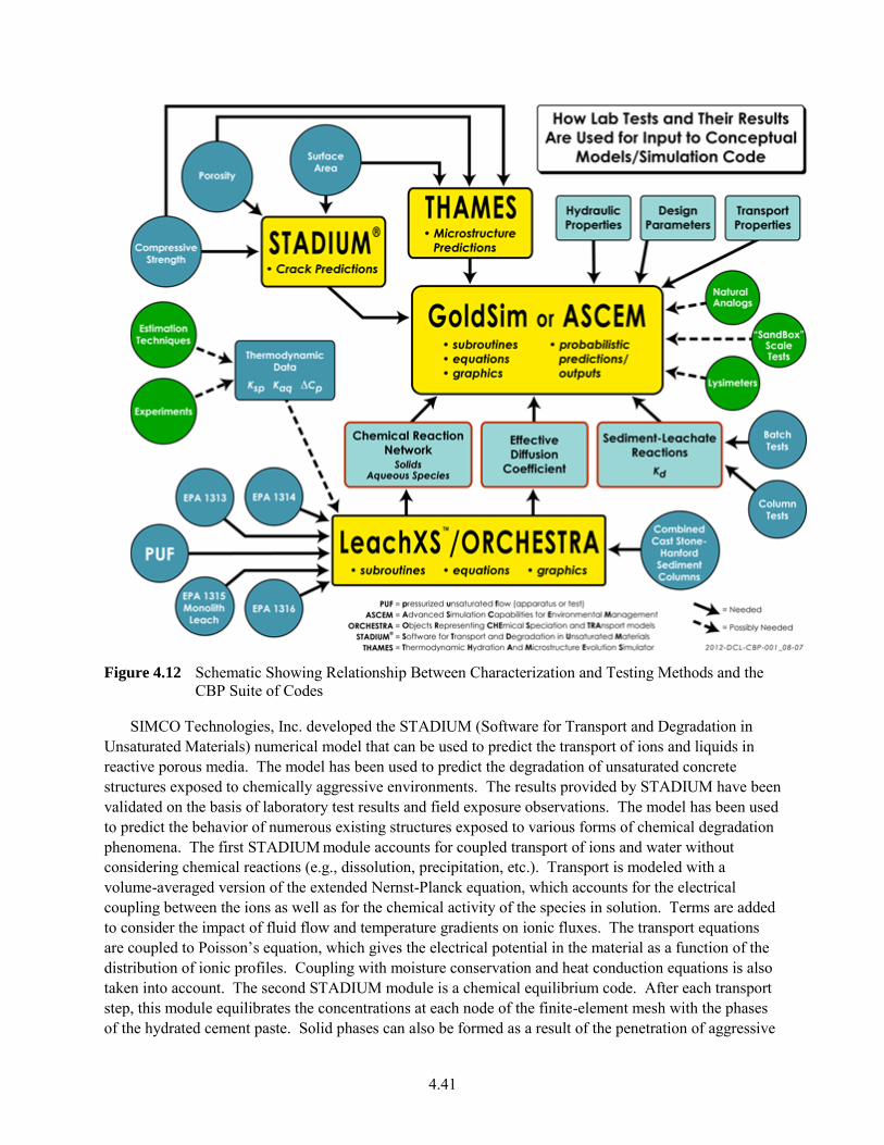
4.41
Figure 4.12 Schematic Showing Relationship Between Characterization and Testing Methods and the
CBP Suite of Codes
SIMCO Technologies, Inc. developed the STADIUM (Software for Transport and Degradation in Unsaturated Materials) numerical model that can be used to predict the transport of ions and liquids in reactive porous media. The model has been used to predict the degradation of unsaturated concrete structures exposed to chemically aggressive environments. The results provided by STADIUM have been validated on the basis of laboratory test results and field exposure observations. The model has been used to predict the behavior of numerous existing structures exposed to various forms of chemical degradation phenomena. The first STADIUM module accounts for coupled transport of ions and water without considering chemical reactions (e.g., dissolution, precipitation, etc.). Transport is modeled with a volume-averaged version of the extended Nernst-Planck equation, which accounts for the electrical coupling between the ions as well as for the chemical activity of the species in solution. Terms are added to consider the impact of fluid flow and temperature gradients on ionic fluxes. The transport equations are coupled to Poisson’s equation, which gives the electrical potential in the material as a function of the distribution of ionic profiles. Coupling with moisture conservation and heat conduction equations is also taken into account. The second STADIUM module is a chemical equilibrium code. After each transport step, this module equilibrates the concentrations at each node of the finite-element mesh with the phases of the hydrated cement paste. Solid phases can also be formed as a result of the penetration of aggressive
4.42
species into the porous network of the material. The variation of solid phases will lead to local variations in porosity. These variations are likely to affect the transport properties of the material locally. STADIUM takes this locally varying phenomenon into account in the transport module described above.
THAMES (Thermodynamic Hydration And Microstructure Evolution Simulator) is a model/code that describes cementitious binder microstructures and calculates important engineering properties during hydration and degradation. THAMES serves as a “microprobe” that will be called by other programs in the integrated CBP model to update microstructure (e.g. pore space volume and connectedness) and properties (e.g. diffusivity, elastic moduli) as hydration and degradation proceed through the projected lifetime of the barrier material. THAMES is built around a thermodynamic engine, which rapidly predicts bulk mineral phase volumes as a function of time in cement paste microstructures evolving by hydration or degradation phenomena. However, the bulk information alone is insufficient to make accurate predictions of transport properties and mechanical properties; microstructure information is also required. A model must predict not only the overall phase quantities, but also how these phases are distributed in space. THAMES ultimately will include 1) a module for generating a representative three-dimensional (3-D) initial microstructure of cementitious particles in water (GENMIC), 2) a module for simulating microstructure changes (THAMES) guided by the thermodynamic calculations (e.g., GEMS), and 3) a module for calculating the elastic moduli, DC conductivity/diffusivity, and permeability on the predicted cement paste and mortar/concrete microstructure
The CBP is generally focused on phenomena occurring in the near field, within and adjoining engineered structures and contaminant source zones, at the centimeter to meter scale. Software modules are expected to be developed by the CBP and used by the Advanced Simulation Capability for Environmental Management (ASCEM) system model for source zone material properties and/or contaminant flux.
Regardless of which of the two suites of codes is chosen to model the long-term fate of contaminants for the LAW Cast Stone waste form, the process for developing the improved waste form release model relies on the laboratory testing activities discussed in this test plan to quantify the needed parameters used in the numerical predictive long-term PA models to simulate the key reactions and/or processes affecting release over long time frames. The technical defensibility of the release model is bolstered by showing allegiance to or similarity between the numerical release algorithms to basic thermodynamic and kinetic theories.
4.14.4 Validation Support
The waste form leach tests required to support long-term risk assessment and PA start with well-constrained tests using leachants germane to the IDF (see Table 4.8) contacting Cast Stone. Leach tests then progress to multicomponent tests where the Cast Stone waste form is surrounded by the backfill Hanford formation sediments and perhaps canister metal and/or canister corrosion products. Each of the leach tests is used either to identify the final minerals formed by interaction of the starting solids with water (i.e., the weathering process) or to obtain the values for parameters required in the diffusion-based release rate-law used to quantify the release of major and minor constituents in the waste form/package. Once the final minerals that are formed by the weathering process are established, and the kinetic rate-law equation parameters or effective diffusion-controlled release rate for individual Cast Stone minerals/solid phases are established, a defensible conceptual model for long-term waste form release can be
4.43
constructed. Once there are acceptable predictions for the waste package release, other chemical processes germane to the entire IDF disposal system, such as the subsequent interactions of leachates with Hanford formation sediments, will be modeled. These predictions can be compared with actual packed-column, flow-through tests or two- and three-dimensional sand box tests or even decades or longer field-scale lysimeter tests if there is a need for longer-term validation. If relevant natural analogs can be found, findings from detailed characterization of their properties and surroundings can be used to further validate long-term predictions produced from the IDF system computer code.
The validation efforts will compare such natural analog results with predictions from the IDF system PA computer models. The PA code predictions use numerical representations of controlling mechanisms based as much as possible on known physicochemical theories or laws. The individual components (rectangular boxes in Figure 4.10) will be used with Cast Stone laboratory-test–derived input values tempered with results from flow-through “system tests” that include the Cast Stone waste form and surrounding sediments. The scale of the “system tests” may include laboratory columns, meter-sized sand boxes, and several meter-scaled field lysimeters. When practical, the “system tests” will be conducted so that reactions can be accelerated using appropriate higher temperatures, leachant flow rates, or other stressors. If found, relevant natural analogs will be the final method used to validate the IDF system PA predictions. These activities will support the resolution of issue 13.1 in Table B.1.

5.1
5.0 Hanford Secondary Waste Simulants for Cast Stone Tests
A number of simulants have been used for secondary-waste Cast Stone waste form product and process testing and for evaluation of alternative low-temperature waste forms for WTP secondary-waste solidification options. The simulants described below provide a starting point for the Cast Stone technology maturation and for the WFQ process. It is expected that, through the maturation process, the waste constituents most impactful to the Cast Stone immobilization process will be identified, and the simulants used for WFQ testing may be modified to demonstrate the robustness of the process and waste form for the expected range of those impactful components.
Most of the WFQ testing for Cast Stone can be conducted with nonradioactive simulants of the projected feeds for the Cast Stone immobilization process. The chemistry of the nonradioactive isotopes is the same as that of the radioisotopes. Technetium does not have a stable isotope. Though the concentration of 99Tc is relatively low in the secondary wastes, its long half-life (2.1 105 years) and relatively high mobility in the environment make it a significant contributor to the environmental impacts of waste disposal in the IDF.
Simulant development begins with identifying and defining the sources and compositions of the sources of wastes to be treated and solidified. The ETF will receive aqueous wastes from a number of sources for treatment and solidification. Waste compositions are available from existing sources including ERDF and mixed-waste disposal-trench leachates and the 242-A Evaporator condensates. The compositions of wastes from other sources such as the IDF leachates and WTP secondary wastes must be estimated by other means including flowsheet modeling.
Waste definition must also consider the treatment steps within the ETF before the wastes are ready for solidification. These treatment steps include (DOE-RL 1997):
surge tank – waste receipt and surge capacity
filtration – for suspended solids removal
ultraviolet light/hydrogen peroxide oxidation – organic destruction
pH adjustment with sulfuric acid or sodium hydroxide
hydrogen peroxide decomposition – removal of excess hydrogen peroxide
degasification – removal of carbon dioxide
reverse osmosis – removal of dissolved solids and radionuclides
ion exchange – removal of dissolved solids and radionuclides
The filter backwash, concentrate from the reverse osmosis and the regeneration waste from the ion exchange are collected and become the waste stream to be solidified in the Cast Stone. Flowsheet modeling and/or chemical analyses of this waste stream describe the final waste composition to the Cast Stone process. Simulants can then be developed for this final waste stream.
The following sections describe secondary-waste simulants that have been developed and used for evaluation of low-temperature waste forms for solidifying WTP secondary wastes. Spikes of 99Tc, RCRA
5.2
and underlying hazardous waste constituent metals and organics can be added as needed to address specific WFQ requirements. Also, as tests are conducted with actual wastes, simulants may need to be developed for those specific compositions for testing to demonstrate the correlation between the simulants and actual wastes to validate the simulant work.
5.1 Waste Feed Envelope Definition
The following sections describe flowsheet modeling to estimate WTP secondary-waste compositions and to estimate the impact of processing various current and future wastes through the ETF treatment process. Waste feed envelope definition is an ongoing activity as the WTP flowsheet matures and the tools to model the WTP and the ETF flowsheets are refined.
5.1.1 WTP Secondary-Waste Simulants
Because the WTP is still under construction, there are no actual secondary wastes to provide a basis for simulants. Therefore, flowsheet modeling is currently used to estimate the composition of the future WTP secondary waste to be treated and solidified in ETF. Two sets of secondary-waste effluent compositions have been identified through flowsheet modeling that would capture anticipated variations in composition over the course of the Hanford tank waste cleanup mission. The compositions are to be used for secondary waste form development and performance testing that would support selection, and subsequent optimization and qualification, of a preferred immobilized secondary waste form.
The first set of simulants was developed in 2010 by conducting a statistical cluster analysis of projected monthly average compositions provided by Washington River Protection Solutions (WRPS). These compositions were based on WTP G2 ASPEN flowsheet simulation. The flowsheet simulations provide estimated compositions of the WTP process streams and how the compositions would vary over the course of the WTP mission. The data sets represent sequential “batch” compositions of 10,000 to 100,000 gallons of secondary effluent representing several days to several weeks of WTP operation. Through a statistical evaluation of the data set, a baseline simulant based on medians and two simulants with high chloride and high nitrate and low chloride and low nitrate were selected. More details on the derivation of the WTP secondary-waste compositions can be found in the two previous Cast Stone reports (Pierce et al. 2010; Sundaram et al. 2011).
To date, the Cast Stone studies at PNNL have used five secondary-waste simulants, generally with a composition based on a 2-M sodium concentration as shown in Table 5.1. The compositions of the dissolved species in secondary-waste simulants in general are dominated by sodium and hydroxide with significant concentrations of nitrate and oxalate (representing all organic matter) present in many. The simulant S4, a caustic scrubber/submerged bed scrubber (SBS) blend, differs in that it contains significant amounts of ammonium and is neutral in pH (no free hydroxide) as shown in Table 5.1. In addition, the median composition caustic scrubber waste simulant, S1, was concentrated to sodium concentrations at 4 M and 6 M sodium for some of the tests in order to gather data on the impacts of total waste salt loading on Cast Stone performance. The concentrated simulants with suspended solids—a slurry—were used to make various Cast Stone waste forms (Mattigod et al. 2011).
The projected WTP secondary-waste compositions have varied over time as flowsheets and assumptions have changed. During late 2010 and early 2011, WRPS updated their WTP modeling using
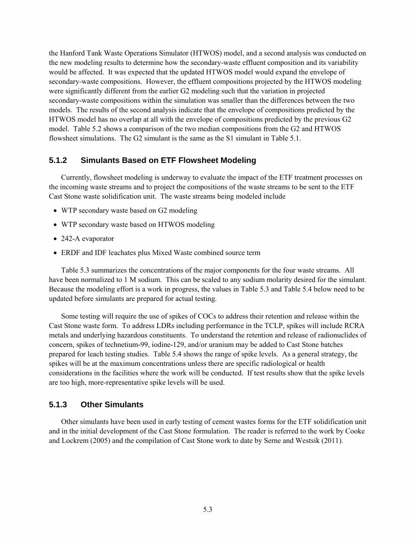
5.3
the Hanford Tank Waste Operations Simulator (HTWOS) model, and a second analysis was conducted on the new modeling results to determine how the secondary-waste effluent composition and its variability would be affected. It was expected that the updated HTWOS model would expand the envelope of secondary-waste compositions. However, the effluent compositions projected by the HTWOS modeling were significantly different from the earlier G2 modeling such that the variation in projected secondary-waste compositions within the simulation was smaller than the differences between the two models. The results of the second analysis indicate that the envelope of compositions predicted by the HTWOS model has no overlap at all with the envelope of compositions predicted by the previous G2 model. Table 5.2 shows a comparison of the two median compositions from the G2 and HTWOS flowsheet simulations. The G2 simulant is the same as the S1 simulant in Table 5.1.
5.1.2 Simulants Based on ETF Flowsheet Modeling
Currently, flowsheet modeling is underway to evaluate the impact of the ETF treatment processes on the incoming waste streams and to project the compositions of the waste streams to be sent to the ETF Cast Stone waste solidification unit. The waste streams being modeled include
WTP secondary waste based on G2 modeling
WTP secondary waste based on HTWOS modeling
242-A evaporator
ERDF and IDF leachates plus Mixed Waste combined source term
Table 5.3 summarizes the concentrations of the major components for the four waste streams. All have been normalized to 1 M sodium. This can be scaled to any sodium molarity desired for the simulant. Because the modeling effort is a work in progress, the values in Table 5.3 and Table 5.4 below need to be updated before simulants are prepared for actual testing.
Some testing will require the use of spikes of COCs to address their retention and release within the Cast Stone waste form. To address LDRs including performance in the TCLP, spikes will include RCRA metals and underlying hazardous constituents. To understand the retention and release of radionuclides of concern, spikes of technetium-99, iodine-129, and/or uranium may be added to Cast Stone batches prepared for leach testing studies. Table 5.4 shows the range of spike levels. As a general strategy, the spikes will be at the maximum concentrations unless there are specific radiological or health considerations in the facilities where the work will be conducted. If test results show that the spike levels are too high, more-representative spike levels will be used.
5.1.3 Other Simulants
Other simulants have been used in early testing of cement wastes forms for the ETF solidification unit and in the initial development of the Cast Stone formulation. The reader is referred to the work by Cooke and Lockrem (2005) and the compilation of Cast Stone work to date by Serne and Westsik (2011).
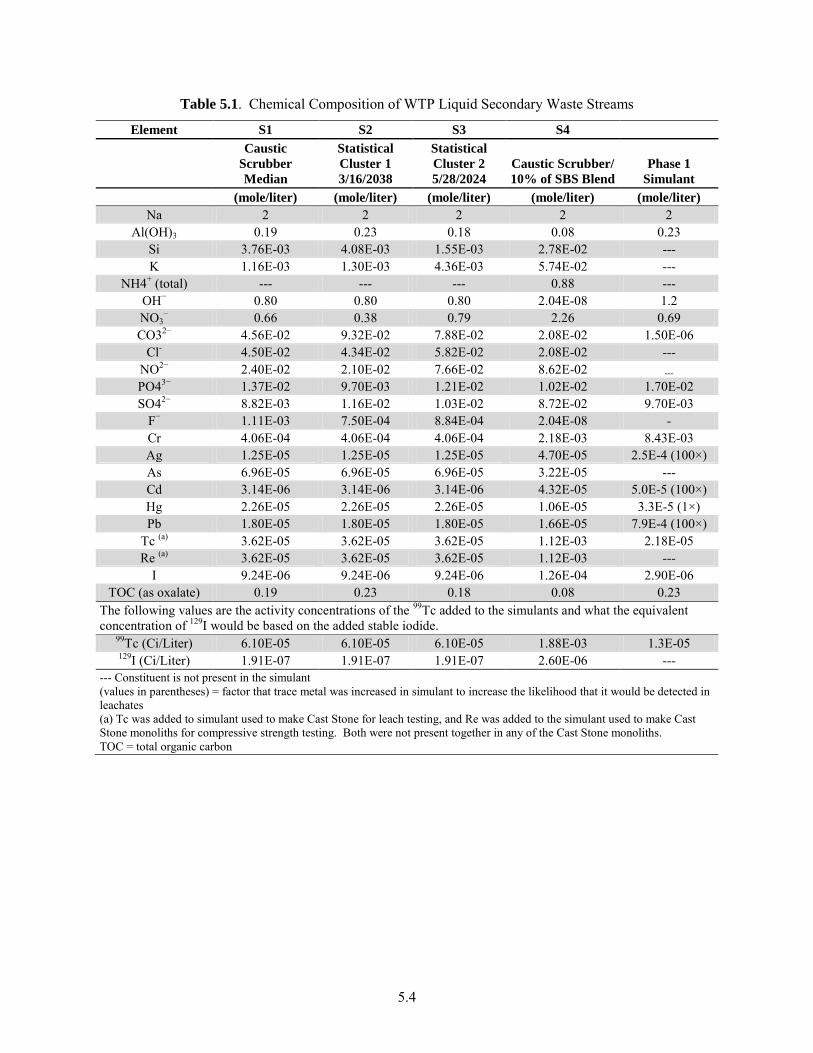
5.4
Table 5.1. Chemical Composition of WTP Liquid Secondary Waste Streams
Element S1 S2 S3 S4
Caustic
Scrubber
Median
Statistical
Cluster 1
3/16/2038
Statistical
Cluster 2
5/28/2024
Caustic Scrubber/
10% of SBS Blend
Phase 1
Simulant
(mole/liter) (mole/liter) (mole/liter) (mole/liter) (mole/liter)
Na 2 2 2 2 2 Al(OH)3 0.19 0.23 0.18 0.08 0.23
Si 3.76E-03 4.08E-03 1.55E-03 2.78E-02 --- K 1.16E-03 1.30E-03 4.36E-03 5.74E-02 ---
NH4+ (total) --- --- --- 0.88 --- OH− 0.80 0.80 0.80 2.04E-08 1.2 NO3
− 0.66 0.38 0.79 2.26 0.69
CO32− 4.56E-02 9.32E-02 7.88E-02 2.08E-02 1.50E-06 Cl- 4.50E-02 4.34E-02 5.82E-02 2.08E-02 ---
NO2− 2.40E-02 2.10E-02 7.66E-02 8.62E-02 ---
PO43− 1.37E-02 9.70E-03 1.21E-02 1.02E-02 1.70E-02 SO42− 8.82E-03 1.16E-02 1.03E-02 8.72E-02 9.70E-03
F− 1.11E-03 7.50E-04 8.84E-04 2.04E-08 - Cr 4.06E-04 4.06E-04 4.06E-04 2.18E-03 8.43E-03 Ag 1.25E-05 1.25E-05 1.25E-05 4.70E-05 2.5E-4 (100×) As 6.96E-05 6.96E-05 6.96E-05 3.22E-05 --- Cd 3.14E-06 3.14E-06 3.14E-06 4.32E-05 5.0E-5 (100×) Hg 2.26E-05 2.26E-05 2.26E-05 1.06E-05 3.3E-5 (1×) Pb 1.80E-05 1.80E-05 1.80E-05 1.66E-05 7.9E-4 (100×)
Tc (a) 3.62E-05 3.62E-05 3.62E-05 1.12E-03 2.18E-05 Re (a) 3.62E-05 3.62E-05 3.62E-05 1.12E-03 ---
I 9.24E-06 9.24E-06 9.24E-06 1.26E-04 2.90E-06 TOC (as oxalate) 0.19 0.23 0.18 0.08 0.23
The following values are the activity concentrations of the 99Tc added to the simulants and what the equivalent concentration of 129I would be based on the added stable iodide.
99Tc (Ci/Liter) 6.10E-05 6.10E-05 6.10E-05 1.88E-03 1.3E-05 129I (Ci/Liter) 1.91E-07 1.91E-07 1.91E-07 2.60E-06 ---
--- Constituent is not present in the simulant (values in parentheses) = factor that trace metal was increased in simulant to increase the likelihood that it would be detected in leachates (a) Tc was added to simulant used to make Cast Stone for leach testing, and Re was added to the simulant used to make Cast Stone monoliths for compressive strength testing. Both were not present together in any of the Cast Stone monoliths. TOC = total organic carbon
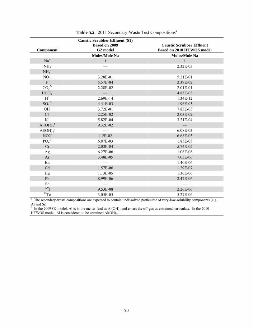
5.5
Table 5.2. 2011 Secondary-Waste Test Compositionsa
Component
Caustic Scrubber Effluent (S1)
Based on 2009
G2 model
Caustic Scrubber Effluent
Based on 2010 HTWOS model
Moles/Mole Na Moles/Mole Na
Na+ 1 1 NH3 — 2.32E-03 NH4
+ — — NO3
- 3.28E-01 5.21E-01 F- 5.57E-04 2.39E-02
CO32- 2.28E-02 2.01E-01
HCO3- — 4.85E-03
H+ 2.69E-14 1.34E-12 SO4
2- 4.41E-03 1.96E-03 OH- 3.72E-01 7.83E-03 Cl- 2.25E-02 2.03E-02 K+ 5.82E-04 3.21E-04
Al(OH)3b 9.32E-02 —
Al(OH)4- — 6.08E-03
NO2- 1.2E-02 6.68E-03 PO4
3- 6.87E-03 1.85E-03 Cr 2.03E-04 5.74E-05 Ag 6.27E-06 1.06E-06 As 3.48E-05 7.05E-06 Ba — 1.40E-06 Cd 1.57E-06 1.29E-07 Hg 1.13E-05 1.36E-06 Pb 8.99E-06 2.47E-06 Se — — 129I 9.53E-08 2.26E-06
99Tc 3.05E-05 5.27E-06 a The secondary-waste compositions are expected to contain undissolved particulate of very-low-solubility components (e.g., Al and Si). b In the 2009 G2 model, Al is in the melter feed as Al(OH)3 and enters the off-gas as entrained particulate. In the 2010 HTWOS model, Al is considered to be entrained Al(OH)4-.
5.6
Table 5.3. ETF Treated Waste Compositions
Chemicals
242-A
Evaporator
ERDF/IDF
Leachate/
Mixed Waste Aspen WTP HTWOS WTP
Moles per Mole Na
Al+3 0.630 — 0.001 — Al(OH)4
- — — — 0.007 Br- — 0.002 — —
Ca+2 0.012 0.359 — — Cl- 0.306 0.529 0.007 0.026
CO2(aq) 0.012 — 0.001 — F- 0.017 0.012 0.001 0.039
Fe+3 0.006 — — — H2O2 0.006 0.003 — 0.002
HCO3- 0.269 0.001 0.013 0.010
K+ 0.028 0.045 — 0.001 Mg+2 0.001 0.238 — —
MnO4- 0.014 — — —
Na+ 1.000 1.000 1.000 1.000 NH3 0.039 — — 0.128 NH4
+ 0.705 — 0.009 2.310 Ni+2 0.004 — — — NO2
- 0.931 0.007 0.006 0.008 NO3
- 10.763 0.392 0.014 0.521 Pb+2 0.015 — — —
PO43- 0.454 — — 0.002 Si+4 0.053 0.060 — 0.001
SO42- 6.278 0.417 0.474 1.428
Sr+2 0.001 — — — U(TOTAL) 0.002 0.001 — —
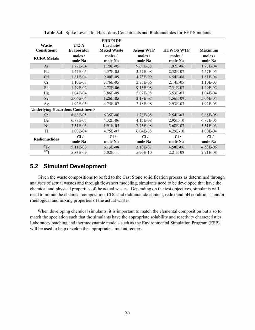
5.7
Table 5.4. Spike Levels for Hazardous Constituents and Radionuclides for EFT Simulants
Waste
Constituent
242-A
Evaporator
ERDF/IDF
Leachate/
Mixed Waste Aspen WTP HTWOS WTP Maximum
RCRA Metals moles /
mole Na
moles /
mole Na
moles /
mole Na
moles /
mole Na
moles /
mole Na
As 1.77E-04 1.29E-05 9.69E-08 1.92E-06 1.77E-04 Ba 1.47E-05 4.57E-05 3.52E-08 2.32E-07 4.57E-05 Cd 1.81E-04 9.00E-09 4.73E-09 4.54E-08 1.81E-04 Cr 1.10E-03 3.76E-05 2.75E-06 2.14E-05 1.10E-03 Pb 1.49E-02 2.72E-06 9.13E-08 7.31E-07 1.49E-02 Hg 1.04E-04 3.86E-09 5.07E-08 3.53E-07 1.04E-04 Se 5.06E-04 1.26E-05 2.18E-07 1.56E-09 5.06E-04 Ag 1.92E-05 4.75E-07 3.18E-08 2.93E-07 1.92E-05
Underlying Hazardous Constituents
Sb 8.68E-05 6.35E-06 1.28E-08 2.54E-07 8.68E-05 Be 6.87E-05 4.32E-06 4.15E-08 2.95E-10 6.87E-05 Ni 3.51E-03 1.91E-05 7.75E-08 5.68E-07 3.51E-03 Tl 1.00E-04 4.75E-07 6.04E-08 4.29E-10 1.00E-04
Radionuclides Ci /
mole Na
Ci /
mole Na
Ci /
mole Na
Ci /
mole Na
Ci /
mole Na 99Tc 5.11E-08 6.13E-08 3.10E-07 4.58E-06 4.58E-06 129I 5.83E-09 5.02E-11 5.90E-10 2.21E-08 2.21E-08
5.2 Simulant Development
Given the waste compositions to be fed to the Cast Stone solidification process as determined through analyses of actual wastes and through flowsheet modeling, simulants need to be developed that have the chemical and physical properties of the actual wastes. Depending on the test objectives, simulants will need to mimic the chemical composition, COC and radionuclide content, redox and pH conditions, and/or rheological and mixing properties of the actual wastes.
When developing chemical simulants, it is important to match the elemental composition but also to match the speciation such that the simulants have the appropriate solubility and reactivity characteristics. Laboratory batching and thermodynamic models such as the Environmental Simulation Program (ESP) will be used to help develop the appropriate simulant recipes.

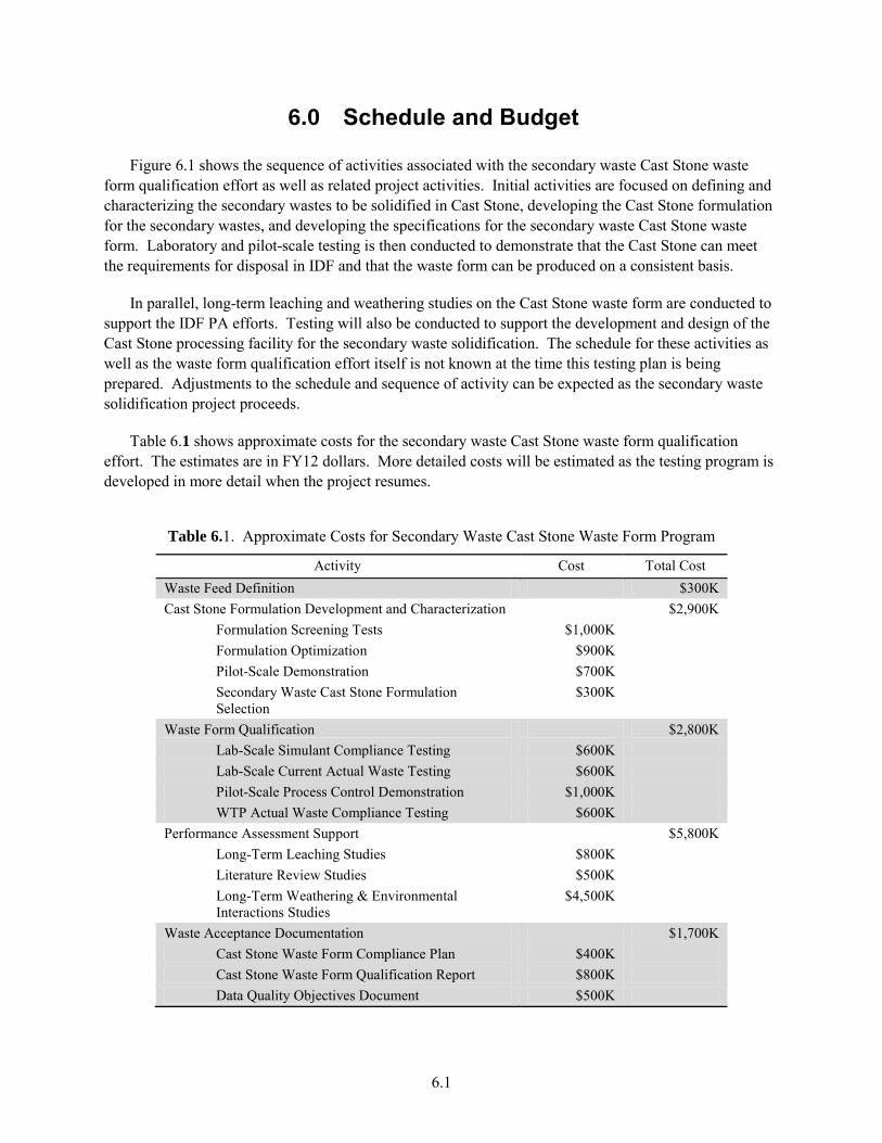
6.1
6.0 Schedule and Budget
Figure 6.1 shows the sequence of activities associated with the secondary waste Cast Stone waste form qualification effort as well as related project activities. Initial activities are focused on defining and characterizing the secondary wastes to be solidified in Cast Stone, developing the Cast Stone formulation for the secondary wastes, and developing the specifications for the secondary waste Cast Stone waste form. Laboratory and pilot-scale testing is then conducted to demonstrate that the Cast Stone can meet the requirements for disposal in IDF and that the waste form can be produced on a consistent basis.
In parallel, long-term leaching and weathering studies on the Cast Stone waste form are conducted to support the IDF PA efforts. Testing will also be conducted to support the development and design of the Cast Stone processing facility for the secondary waste solidification. The schedule for these activities as well as the waste form qualification effort itself is not known at the time this testing plan is being prepared. Adjustments to the schedule and sequence of activity can be expected as the secondary waste solidification project proceeds.
Table 6.1 shows approximate costs for the secondary waste Cast Stone waste form qualification effort. The estimates are in FY12 dollars. More detailed costs will be estimated as the testing program is developed in more detail when the project resumes.
Table 6.1. Approximate Costs for Secondary Waste Cast Stone Waste Form Program
Activity Cost Total Cost Waste Feed Definition $300K Cast Stone Formulation Development and Characterization $2,900K
Formulation Screening Tests $1,000K Formulation Optimization $900K Pilot-Scale Demonstration $700K Secondary Waste Cast Stone Formulation Selection
$300K
Waste Form Qualification $2,800K Lab-Scale Simulant Compliance Testing $600K Lab-Scale Current Actual Waste Testing $600K Pilot-Scale Process Control Demonstration $1,000K WTP Actual Waste Compliance Testing $600K
Performance Assessment Support $5,800K Long-Term Leaching Studies $800K Literature Review Studies $500K Long-Term Weathering & Environmental Interactions Studies
$4,500K
Waste Acceptance Documentation $1,700K Cast Stone Waste Form Compliance Plan $400K Cast Stone Waste Form Qualification Report $800K Data Quality Objectives Document $500K
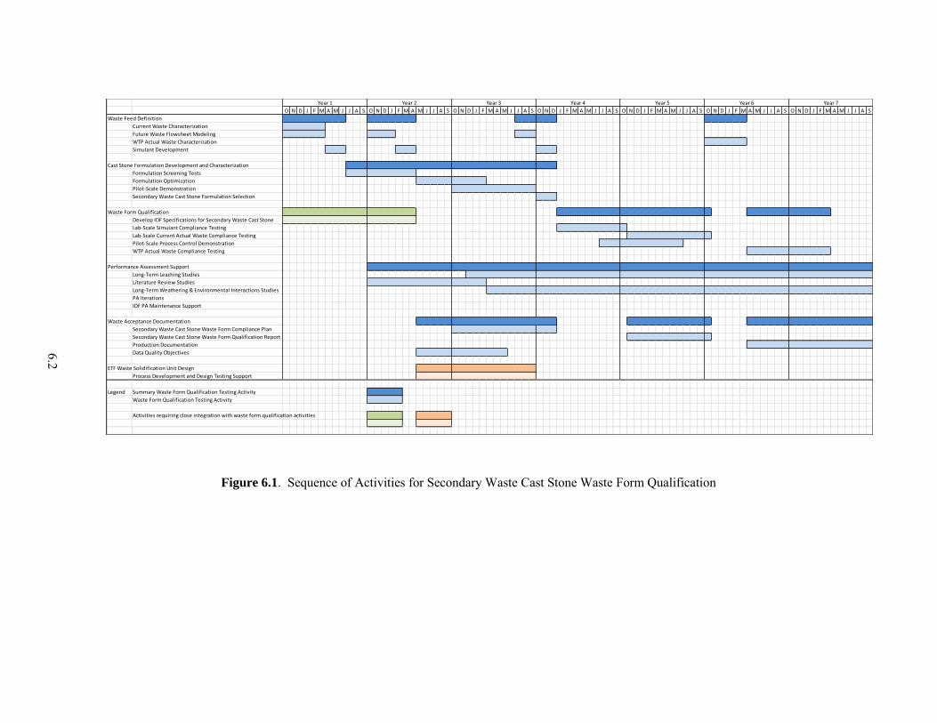
6.2
Figure 6.1. Sequence of Activities for Secondary Waste Cast Stone Waste Form Qualification
O N D J F M A M J J A S O N D J F M A M J J A S O N D J F M A M J J A S O N D J F M A M J J A S O N D J F M A M J J A S O N D J F M A M J J A S O N D J F M A M J J A S
Waste Feed Definition
Current Waste Characterization
Future Waste Flowsheet Modeling
WTP Actual Waste Characterization
Simulant Development
Cast Stone Formulation Development and Characterization
Formulation Screening Tests
Formulation Optimization
Pilot-Scale Demonstration
Secondary Waste Cast Stone Formulation Selection
Waste Form Qualification
Develop IDF Specifications for Secondary Waste Cast Stone
Lab-Scale Simulant Compliance Testing
Lab-Scale Current Actual Waste Compliance Testing
Pilot-Scale Process Control Demonstration
WTP Actual Waste Compliance Testing
Performance Assessment Support
Long-Term Leaching Studies
Literature Review Studies
Long-Term Weathering & Environmental Interactions Studies
PA Iterations
IDF PA Maintenance Support
Waste Acceptance Documentation
Secondary Waste Cast Stone Waste Form Compliance Plan
Secondary Waste Cast Stone Waste Form Qualification Report
Production Documentation
Data Quality Objectives
ETF Waste Solidification Unit Design
Process Development and Design Testing Support
Legend Summary Waste Form Qualification Testing Activity
Waste Form Qualification Testing Activity
Activities requiring close integration with waste form qualification activities
Year 6 Year 7Year 1 Year 2 Year 3 Year 4 Year 5
7.1
7.0 Quality Assurance
The WFQ work and testing to support PA analyses outlined in this testing plan will be performed in accordance with a project-specific Quality Assurance Program (QAP). The QAP will be based on the following requirements:
10 CFR 830, Subpart A, “Quality Assurance Requirements.”
DOE Order 414.1D (dated 4/25/2011, supersedes DOE O 414.1C) (DOE 2011), Quality Assurance.
The QAP will use the following consensus standards:
ASME NQA-1, Quality Assurance Requirements for Nuclear Facility Applications, Part 1,
Requirements for Quality Assurance Programs for Nuclear Facilities.
ASME NQA-1, Part II, Subpart 2.7, Quality Assurance Requirements for Computer Software for
Nuclear Facility Applications.
ASME NQA-1, Part IV, Subpart 4.2, Guidance on Graded Application of Quality Assurance (QA) for
Nuclear-Related Research and Development.
Further, for data collected in support of environmental regulatory activities, the QAP will address the QA/QC requirements specified in the Hanford Analytical Services Quality Assurance Requirements
Documents (HASQARD) (DOE-RL 1998). The PNNL document for implementing HASQARD is Conducting Analytical Work in Support of Regulatory Programs (CAWSRP). Data Quality Objectives established in CAWSRP were generated in accordance with HASQARD requirements.
Where appropriate, field experiment and sampling and analysis plans will be based on application of the data quality objectives process in accordance with the Guidance on Systematic Planning Using the
Data Quality Objectives Process (EPA QA/G-4) (EPA/240/B-06/001) (EPA 2000).
Subcontractors and suppliers will be required to develop and implement QA programs that meet the QA requirements of the project QAP.

8.1
8.0 References
10 CFR 61.56. 2009. “Waste Characteristics.” Code of Federal Regulations, U.S. Nuclear Regulatory Commission.
10 CFR 830. 2010. “Nuclear Safety Management.” Code of Federal Regulations, U.S. Department of Energy.
40 CFR 261. 2010. “Identification and Listing of Hazardous Waste.” Code of Federal Regulations, U.S. Environmental Protection Agency.
40 CFR 268. 2010. “Land Disposal Restrictions.” Code of Federal Regulations, U.S. Environmental Protection Agency.
Albenesius EL. 2001. Computer Modeling of Saltstone Landfills by Intera Environmental Consultants.
DPST-83-529, Savannah River Site, Aiken, South Carolina.
Angus MJ and FP Glasser. 1985. “The Chemical Environment in Cement Matrices.” In Materials
Research Society Symposium Proceedings, 50:547–556.
ANSI/ANS—American National Standards Institute/American Nuclear Society. 1992. Solid Radioactive
Waste Processing System for Light-Water-Cooled Reactor Plants; Appendix B - Testing for Free Liquids
in Solidified Matrices. ANSI/ANS-55.1, La Grange Park, Illinois.
ANSI/ANS—American National Standards Institute/American Nuclear Society. 2003. Measurement of
the Leachability of Solidified Low-Level Radioactive Wastes by a Short Term Test Procedure. ANSI/ANS-16.1, La Grange Park, Illinois.
ASME—American Society of Mechanical Engineers. 2000. Quality Assurance Requirements for
Nuclear Facility Applications. NQA-1, Washington, D.C.
ASTM—American Society for Testing and Materials. 1985. Standard Test Method for Thermocycling of
Electroplated Plastics. ASTM B553, West Conshohocken, Pennsylvania.
ASTM—American Society for Testing and Materials. 1996. Standard Practice for Determining
Resistance of Plastics to Bacteria. ASTM G22, West Conshohocken, Pennsylvania.
ASTM—American Society for Testing and Materials. 2000. Practice for Dissolving Glass Containing
Radioactive and Mixed Waste for Chemical and Radiochemical Analysis. ASTM C1463, West Conshohocken, Pennsylvania.
ASTM—American Society for Testing and Materials. 2001R. Standard Test Method for Distribution
Ratios by the Short-Term Batch Method. ASTM D4319–93, West Conshohocken, Pennsylvania.
ASTM—American Society for Testing and Materials. 2007. Standard Practice for Measurement of the
Glass Dissolution Rate Using the Single-Pass Flow-Through Test Containing Radioactive and Mixed
Waste for Chemical and Radiochemical Analysis. ASTM C1662, West Conshohocken, Pennsylvania.
8.2
ASTM—American Society for Testing and Materials. 2008a. Standard Test Methods for Determining
Chemical Durability of Nuclear, Hazardous, and Mixed Waste Glasses and Multiphase Glass Ceramics:
The Product Consistency Test (PCT). ASTM C1285, West Conshohocken, Pennsylvania.
ASTM—American Society for Testing and Materials. 2008b. Standard Test Method for Accelerated
Leach Test for Diffusive Releases from Solidified Waste and a Computer Program to Model Diffusive,
Fractional Leaching from Cylindrical Waste Forms. ASTM C1308, West Conshohocken, Pennsylvania.
ASTM—American Society for Testing and Materials. 2008c. Standard Test Methods for Time of Setting
of Hydraulic Cement by Vicat Needle. ASTM C191, West Conshohocken, Pennsylvania.
ASTM—American Society for Testing and Materials. 2009a. Standard Test Method for Compressive
Strength of Cylindrical Concrete Specimens. ASTM C39/C39M, West Conshohocken, Pennsylvania.
ASTM—American Society for Testing and Materials. 2009b. Standard Test Method for Measuring
Waste Glass or Glass Ceramic Durability by Vapor Hydration Test. ASTM C1663, West Conshohocken, Pennsylvania.
ASTM—American Society for Testing and Materials. 2009d. Standard Practice for Determining
Resistance of Synthetic Polymeric Materials to Fungi. ASTM G21, West Conshohocken, Pennsylvania.
Bacon DH and BP McGrail. 2001. Waste Form Release Calculations for the 2001 Immobilized Low-
Activity Waste Performance Assessment. PNNL-13369, Pacific Northwest National Laboratory, Richland, Washington.
Bacon DH, MD White, and BP McGrail. 2000. Subsurface Transport Over Reactive Multiphases
(STORM): A General, Coupled, Nonisothermal Multiphase Flow, Reactive Transport, and Porous
Medium Alteration Simulator, Version 2, User’s Guide. PNNL-13108, Pacific Northwest National Laboratory, Richland, Washington.
Bacon DH, MD White, and BP McGrail. 2004. Subsurface Transport Over Reactive Multiphases
(STORM): A Parallel, Coupled, Nonisothermal Multiphase Flow, Reactive Transport, and Porous
Medium Alteration Simulator, Version 3.0, User’s Guide. PNNL-14783, Pacific Northwest National Laboratory, Richland, Washington.
Bacon DH and BP McGrail. 2005. Waste Form Release Calculations for the 2005 Integrated Disposal
Facility Performance Assessment. PNNL-15198, Pacific Northwest National Laboratory, Richland, Washington.
Brown CF, KN Geiszler, and TS Vickerman. 2005. “Extraction and Quantitative Analysis of Iodine in Solid and Solution Matrixes” Analytical Chemistry 77(21):7062-7066, DOI: 10.1021/ac050972v.
Brunauer S, PH Emmett, and E Teller. 1938. “Adsorption of Gases in Multimolecular Layers.” Journal
of the American Chemical Society 60:309-319.
Crow RF and JD Connolly. 1973. “Atomic Absorption Analysis of Portland Cement and Raw Mix Using Lithium Metaborate Fusion.” J. Test. Evaluation 1:382.
CH2M HILL. 2005. Testing Plan to Support Determination of Equivalent Treatment for Bulk
Vitrification. RPP-Plan-28064, CH2M HILL Hanford Group, Inc., Richland, Washington.
8.3
Chen Y, DW Engel, BP McGrail, and KS Lessor. 1995. AREST-CT V1.0 Software Verification. PNL-10692, Pacific Northwest Laboratory, Richland, Washington.
Chen Y, BP McGrail, and DW Engel. 1997. “Source-term analysis for Hanford low-activity tank waste using the reaction-transport code AREST-CT.” In Scientific Basis for Nuclear Waste Management XX, Pittsburgh, Pennsylvania.
Cook JR. 2000. Radiological Performance Assessment for the E-Area Vaults Disposal Facility.
WSRC-RP-94-0218, Savannah River Site, Aiken, South Carolina.
Cooke, GA and LL Lockrem. 2005. Effluent Treatment Facility Waste Stream Stabilization Testing, RPP-RPT-26851, CH2M HILL Hanford Group, Inc., Richland, Washington.
Dane, JH, and JW Hopmans. 2007. “Hanging Water Column.” In: Encyclopedia of Water Science,
Second Edition, ed. SW Trimble, CRC Press.
De Windt L, S Leclercq, and J van der Lee. 2006. “Assessing the Durability of Nuclear Glass with Respect to Silica Controlling Processes in a Clayey Underground Disposal.” In Scientific Basis for
Nuclear Waste Management XXIX, Mater. Res. Soc. Symp. Proc. 932, ed. P Van Isheghem, September 12–16, 2005, Ghent, Belgium, Warrendale, Pennsylvania.
DOE-RL—U.S. Department of Energy, Richland Operations Office. 1997. Hanford Facility Dangerous
Waste Permit Application, Liquid Effluent Retention Facility and 200 Area Effluent Treatment Facility. DOE/RL-97-03, Richland, Washington.
DOE-ORP—U.S. Department of Energy, Office of River Protection. 2000. WTP Contract. Contract DE-AC27-01RV14136, Richland, Washington, as amended.
DOE-ORP--U.S. Department of Energy, Office of River Protection (DOE-ORP). 2011. River Protection
Project System Plan. ORP-11242, Revision 6, U.S. Department of Energy, Office of River Protection, Richland, Washington.
DOE O 414.1D. 2011. “Quality Assurance.” U.S. Department of Energy, Washington, D.C.
DOE-EM—U.S. Department of Energy Office of Environmental Management. 2008. Technology
Readiness Assessment (TRA) / Technology Maturation Plan (TMP) Process Guide, Washington, D.C.
DOE-RL—U.S. Department of Energy, Richland Operations Office. 1998. Hanford Analytical Services
Quality Assurance Requirements Documents. DOE/RL-96-68, Richland, Washington.
Ecology—Washington State Department of Ecology. 2008. Dangerous Waste Portion of the Resource
Conservation and Recovery Act Permit for the Treatment, Storage and Disposal of Dangerous Waste at
the Hanford Facility. WA 7890008967, as amended, Olympia, Washington.
EPA—U.S. Environmental Protection Agency. 1999. Understanding Variation in Partition Coefficient,
Kd, Values: Volume I. The Kd Model, Methods of Measurement, and Application of Chemical Reaction
Codes. EPA 402-R-99-004A, Washington, D.C.
EPA—U.S. Environmental Protection Agency. 2000. Guidance for the Data Quality Objectives Process. EPA QA/G-4, Washington, D.C.
8.4
EPA—U.S. Environmental Protection Agency. 2008. Methods for Evaluating Solid Waste,
Physical/Chemical Methods. SW-846, Washington, D.C.
EPA—U.S. Environmental Protection Agency. 2009a. Method 1313: Leaching Test (Liquid-Solid
Partitioning as a Function of Extract pH) of Constitutents in Solid Materials using a Parallel Batch
Extraction Test (DRAFT). U.S. Environmental Protection Agency, Washington, D.C.
EPA—U.S. Environmental Protection Agency. 2009b. Method 1314: Leaching Test (Liquid-Solid
Partitioning as a Function of Liquid-Solid Ratio) of Constituents in Solid Materials using an Up-Flow
Perculation Column (DRAFT). U.S. Environmental Protection Agency, Washington, D.C.
EPA—U.S. Environmental Protection Agency. 2009c. Mass Transfer Rates of Constituents in Monolith
or Compacted Granular Materials Using a Semi-Dynamic Tank Leaching Test. Draft Method 1315, Washington, D.C.
EPA—U.S. Environmental Protection Agency. 2009d. Method 1316: Leaching Test (Liquid-Solid
Partitioning as a Function of Liquid-to-Solid Ratio) of Constituents in Solid Materials using a Parallel
Batch Extraction Test (DRAFT). U.S. Environmental Protection Agency, Washington, D.C.
Freedman VL, ZF Zhang, JM Keller, and Y Chen. 2007. Development of Waste Acceptance Criteria at
221-U Building: Initial Flow and Transport Scoping Calculations. PNNL-16585, Pacific Northwest National Laboratory, Richland, Washington.
Freedman VL and MD White. 2007. STOMP Software Test Plan. PNNL-SA-54022, Pacific Northwest National Laboratory, Richland, Washington.
Furhmann M, JH Heiser, R Pietrzak, EM Franz, and P Colombo. 1990. Users’ Guide For the
Accelerated Leach Test Computer Program. BNL-52267, Brookhaven National Laboratory, Upton, New York.
Gin S, A Verney-Carron, and G Libourel. 2009. “Use of Archaeological Glass to Predict the Long-Term Behavior of HLW.” In Scientific Basis for Nuclear Waste Management XXXIII, Mater. Res. Soc. Symp. Proc. 1193, eds. BE Burakov and AS Aloy, May 24-29, 2009, St. Petersburg, Russia, Warrendale, Pennsylvania.
Grambow B and E Giffaut. 2006. “Coupling of Chemical Processes in the Near Field.” In Scientific
Basis for Nuclear Waste Management XXIX, Mater. Res. Soc. Symp. Proc. 932, ed. P Van Isheghem, September 12–16, 2005, Ghent, Belgium, Warrendale, Pennsylvania.
Horton R, PJ Wierenga, and DR Nielsen. 1982. “A Rapid Technique for Obtaining Uniform Water Content Distributions in Unsaturated Soil Columns.” Soil Sci. 133:397-399.
Jantzen CM and NE Bibler. 2008. The Product Consistency Test (PCT): How and Why It Was
Developed. SRNS-STI-2008-00110, Savannah River National Laboratory, Aiken, South Carolina.
Krupka KM, RJ Serne, and DI Kaplan. 2004. Geochemical Data Package for the 2005 Hanford
Integrated Disposal Facility Performance Assessment. PNNL-13037 Rev. 2, Pacific Northwest National Laboratory, Richland, Washington.
Lasaga AC. 1998. Kinetic Theory in the Earth Sciences. Princeton University Press, Princeton, New Jersey.
8.5
Lee W and B Batchelor. 2003. “Reductive Capacity of Natural Reductants.” Environmental Science
Technology 37:535-541.
Mann FM, KC Burgard, WR Root, RJ Puigh, SH Finfrock, R Khaleel, DH Bacon, EJ Freeman, BP McGrail, SK Wurstner, and PE LaMont. 2001. Hanford Immobilized Low-Activity Waste
Performance Assessment: 2001 Version. DOE/ORP-2000-24 Rev. 0., U.S. Department of Energy, Office of River Protection, Richland, Washington.
Mann FM, RJ Puigh, R Khaleel, S Finfrock, BP McGrail, DH Bacon, and RJ Serne. 2003. Risk
Assessment Supporting the Decision on the Initial Selection of Supplemental ILAW Technologies. RPP-17675 Rev. 0, CH2M HILL Hanford Group, Inc., Richland, Washington.
Mattigod SV, JH Westsik, Jr., CW Chung, MJ Lindberg, and KE Parker. 2011. Waste Acceptance
Testing of Secondary Waste Forms: Cast Stone, Ceramicrete and DuraLith. PNNL-20632, Pacific Northwest National Laboratory, Richland, Washington.
McGrail BP, DH Bacon, JP Icenhower, FM Mann, RJ Puigh, HT Schaef, and SV Mattigod. 2001. “Near-field performance assessment for a low-activity waste glass disposal system: Laboratory testing to modeling results.” Journal of Nuclear Materials 298:95–111.
McGrail BP, DH Bacon, RJ Serne, and EM Pierce. 2003. A Strategy to Assess Performance of Selected
Low-Activity Waste Forms in an Integrated Disposal Facility. PNNL-14362, Pacific Northwest National Laboratory, Richland, Washington.
McLoughlin SD, NC Hyatt, RJ Hand, and WE Lee. 2006. “Corrosion of Archaeological Model Glasses After 32 Years of Burial at Ballidon.” In Scientific Basis for Nuclear Waste Management XXIX, Mater. Res. Soc. Symp. Proc. 932, ed. P Van Isheghem, September 12–16, 2005, Ghent, Belgium, Warrendale, Pennsylvania.
Mendel JE. 1983. Nuclear Waste Materials Handbook – Waste Form Test Methods. DOE/TIC-11400, Materials Characterization Center, Battelle—Pacific Northwest Laboratories, Richland, Washington.
Mitsui S, H Makino, M Inagaki, and T Ebina. 2009. “Impact of Silicon Migration Through Buffer Material on the Lifetime of Vitrified Waste.” In Scientific Basis for Nuclear Waste Management XXXIII, Mater. Res. Soc. Symp. Proc. 1193, ed. BE Burakov and AS Aloy, May 24-29, 2009, St. Petersburg, Russia, Warrendale, Pennsylvania.
Nichols WE and MD White. 2007a. Project Management Plan for Subsurface Transport Over Multiple
Phases (STOMP) Software Maintenance and Development. PNNL-SA-54024, Pacific Northwest National Laboratory, Richland, Washington.
Nichols WE and MD White. 2007b. Software Design Description For Subsurface Transport Over
Multiple Phases (STOMP) Software. PNNL-SA-54078, Pacific Northwest National Laboratory, Richland, Washington.
NRC—U.S. Nuclear Regulatory Commission. 1991. Technical Position on Waste Form, Rev. 1, Low-Level Waste. Division Management Branch, Office of Nuclear Material Safety and Safeguards, Washington, D.C.
Peters MT and RC Ewing. 2007. “A Science-Based Approach to Understanding Waste Form Durability in Open and Closed Nuclear Fuel Cycles.” In Scientific Basis for Nuclear Waste Management XXX,
8.6
Mater. Res. Soc. Symp. Proc. 985, eds. D Dunn, C Poinssot, B Begg, Nov 27-Dec 1, 2006 Boston, Massachusetts, Warrendale, Pennsylvania.
Pierce EM, BP McGrail, EA Rodriguez, HT Schaef, KP Saripalli, RJ Serne, KM Krupk, PF Martin, SR Baum, KN Geiszler, LR Reed, and WJ Shaw. 2004. Waste Form Release Data Package for the 2005
Integrated Disposal Facility Performance Assessment. PNNL-14805, Pacific Northwest National Laboratory, Richland, Washington.
Pierce EM, U Um, KJ Cantrell, MM Valenta, JH Westsik, Jr., RJ Serne, and KE Parker. 2010. Secondary Waste Form Screening Test Results—Cast Stone and Alkali Alumino-Silicate Geopolymer. Draft report, Pacific Northwest National Laboratory, Richland, Washington.
Powers LJ. 2005. Petrographic Studies on Laboratory-Prepared Mortar Sample. WJE No. 2005.2034, Wiss, Janney, Elstner Associates, Inc., Northbrook, Illinois.
Ramsey AA and RA Robbins. 2012. Secondary Liquid Waste Treatment Cast Stone Technology
Development Plan. RPP-51790, Washington River Protection Solutions, Richland, Washington.
Relyea JF, RJ Serne, and D Rai. 1980. Methods for Determining Radionuclide Retardation Factors:
Status Report. PNL-3349, Pacific Northwest Laboratory Richland, Washington.
Serne RJ, WJ Martin, SB McLaurine, SP Airhart, VL LeGore, and RL Treat. 1987. Laboratory Leach
Tests of HFW Grout and Leachate Adsorption Tests Using Hanford Sediment. PNL-6019, Pacific Northwest Laboratory, Richland, Washington.
Serne RJ and JH Westsik, Jr. 2011. Data Package for Secondary Waste Form Down-Selection—Cast
Stone. PNNL-20706, Pacific Northwest National Laboratory, Richland, Washington.
Sundaram SK, CW Chung, KE Parker, ML Kimura, MM Valenta, CA Burns, SG Pitman, W Um, J Chun, and JH Westsik, Jr. 2011. Secondary Waste Form Development and Optimization—Cast
Stone. PNNL-20159 Rev. 1, Pacific Northwest National Laboratory, Richland, Washington.
Um W, MM Valenta, CW Chung, J Yang, MH Engelhard, RJ Serne, KE Parker, G Wang, KJ Cantrell, and JH Westsik, Jr. 2011. Radionuclide Retention Mechanisms in Secondary Waste-Form Testing:
Phase II. PNNL-20753, Pacific Northwest National Laboratory, Richland, WA.
Van Iseghem P, K Lemmens, M Aertsens, S Gin, I Ribet, B Grambow, JL Crovisier, M Del Nero, E Curti, B Schwyn, B Luckscheiter, and T McMenamin. 2006. “Chemical Durability of High-Level Waste Glass in Repository Environment: Main Conclusions and Remaining Uncertainties from the GLASTAB and GLAMOR Projects.” In Scientific Basis for Nuclear Waste Management XXIX, Mater. Res. Soc. Symp. Proc. 932, P Van Isheghem, September 12–16, 2005, Ghent, Belgium, Warrendale, Pennsylvania.
WAC 173-303. “Dangerous Waste Regulations.” Washington Administrative Code, Olympia, Washington.
White MD and BP McGrail. 2005. STOMP, Subsurface Transport Over Multiple Phases, Version 1.0,
Addendum: ECKEChem, Equilibrium-Conservation-Kinetic Equation Chemistry and Reactive Transport. PNNL-15482, Pacific Northwest National Laboratory, Richland, Washington.
White MD and M Oostrom. 2006. STOMP: Subsurface Transport Over Multiple Phases, Version 4.0,
User’s Guide. PNNL-15782, Pacific Northwest National Laboratory, Richland, Washington.
8.7
White MD and VL Freedman. 2007. STOMP Software Configuration Management Plan. PNNL-SA-54023, Pacific Northwest National Laboratory, Richland, Washington.
Wierenga PJ, MH Young, GW Gee, RG Hills, CT Kincaid, TJ Nicholson, and RE Cady. 1993. Soil
Characterization Methods for Unsaturated Low-Level Waste Sites. PNL-8480, Pacific Northwest Laboratory, Richland, Washington.
Yang L and CI Steefel. 2008. “Kaolinite Dissolution and Precipitation Kinetics at 22°C and pH 4.” Geochimica et Cosmochimica Acta 72:99–116.
Zhang ZF, VL Freedman, and MD White. 2007. Requirements for STOMP Subsurface Transport Over
Multiple Phases. PNNL-SA-54079, Pacific Northwest National Laboratory, Richland, Washington.

Appendix A
Comparison of Specifications Relevant to Low-Activity Waste Cast Stone Waste Form

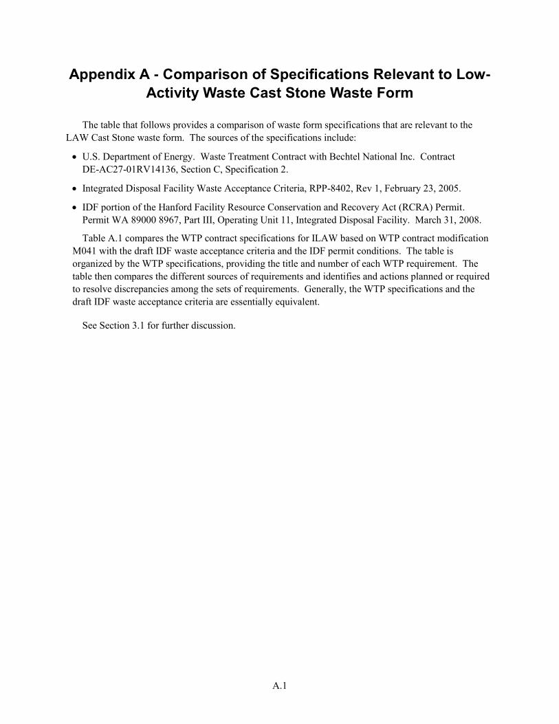
A.1
Appendix A - Comparison of Specifications Relevant to Low-
Activity Waste Cast Stone Waste Form
The table that follows provides a comparison of waste form specifications that are relevant to the LAW Cast Stone waste form. The sources of the specifications include:
U.S. Department of Energy. Waste Treatment Contract with Bechtel National Inc. Contract DE-AC27-01RV14136, Section C, Specification 2.
Integrated Disposal Facility Waste Acceptance Criteria, RPP-8402, Rev 1, February 23, 2005.
IDF portion of the Hanford Facility Resource Conservation and Recovery Act (RCRA) Permit. Permit WA 89000 8967, Part III, Operating Unit 11, Integrated Disposal Facility. March 31, 2008.
Table A.1 compares the WTP contract specifications for ILAW based on WTP contract modification M041 with the draft IDF waste acceptance criteria and the IDF permit conditions. The table is organized by the WTP specifications, providing the title and number of each WTP requirement. The table then compares the different sources of requirements and identifies and actions planned or required to resolve discrepancies among the sets of requirements. Generally, the WTP specifications and the draft IDF waste acceptance criteria are essentially equivalent.
See Section 3.1 for further discussion.
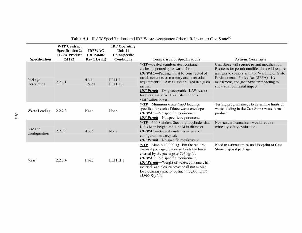
A
.2
Table A.1. ILAW Specifications and IDF Waste Acceptance Criteria Relevant to Cast Stone(a)
Specification
WTP Contract
Specification 2:
ILAW Product
(M152)
IDFWAC
(RPP-8402
Rev 1 Draft)
IDF Operating
Unit 11
Unit-Specific
Conditions Comparison of Specifications Actions/Comments
Package Description 2.2.2.1 4.3.1
1.5.2.1 III.11.I III.11.I.2
WTP—Sealed stainless steel container enclosing poured glass waste form. IDFWAC—Package must be constructed of metal, concrete, or masonry and meet other requirements. LAW is immobilized in a glass matrix. IDF Permit—Only acceptable ILAW waste form is glass in WTP canisters or bulk vitrification boxes.
Cast Stone will require permit modification. Requests for permit modifications will require analysis to comply with the Washington State Environmental Policy Act (SEPA), risk assessment, and groundwater modeling to show environmental impact.
Waste Loading 2.2.2.2 None None
WTP—Minimum waste Na2O loadings specified for each of three waste envelopes. IDFWAC—No specific requirement. IDF Permit—No specific requirement.
Testing program needs to determine limits of waste loading in the Cast Stone waste form product.
Size and Configuration 2.2.2.3 4.3.2 None
WTP—304 Stainless Steel, right cylinder that is 2.3 M in height and 1.22 M in diameter. IDFWAC—Several container sizes and configurations accepted. IDF Permit—No specific requirement.
Nonstandard containers would require critically safety evaluation.
Mass 2.2.2.4 None III.11.H.1
WTP—Mass < 10,000 kg. For the required disposal package, this mass limits the force exerted by the package to 796 kg/ft2. IDFWAC—No specific requirement. IDF Permit—Weight of waste, container, fill material, and closure cover shall not exceed load-bearing capacity of liner (13,000 lb/ft2) (5,900 Kg/ft2).
Need to estimate mass and footprint of Cast Stone disposal package.
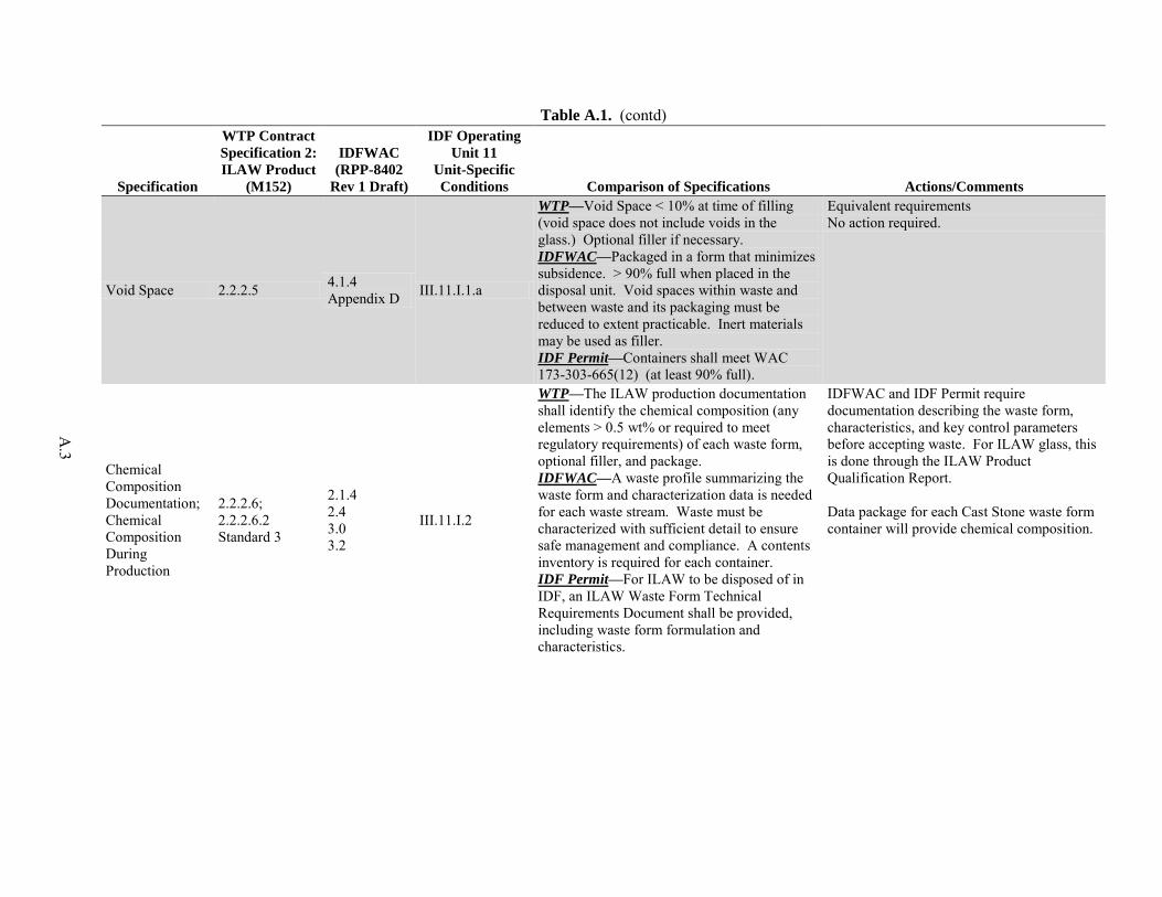
A
.3
Table A.1. (contd)
Specification
WTP Contract
Specification 2:
ILAW Product
(M152)
IDFWAC
(RPP-8402
Rev 1 Draft)
IDF Operating
Unit 11
Unit-Specific
Conditions Comparison of Specifications Actions/Comments
Void Space 2.2.2.5 4.1.4 Appendix D III.11.I.1.a
WTP—Void Space < 10% at time of filling (void space does not include voids in the glass.) Optional filler if necessary. IDFWAC—Packaged in a form that minimizes subsidence. > 90% full when placed in the disposal unit. Void spaces within waste and between waste and its packaging must be reduced to extent practicable. Inert materials may be used as filler. IDF Permit—Containers shall meet WAC 173-303-665(12) (at least 90% full).
Equivalent requirements No action required.
Chemical Composition Documentation; Chemical Composition During Production
2.2.2.6; 2.2.2.6.2 Standard 3
2.1.4 2.4 3.0 3.2
III.11.I.2
WTP—The ILAW production documentation shall identify the chemical composition (any elements > 0.5 wt% or required to meet regulatory requirements) of each waste form, optional filler, and package. IDFWAC—A waste profile summarizing the waste form and characterization data is needed for each waste stream. Waste must be characterized with sufficient detail to ensure safe management and compliance. A contents inventory is required for each container. IDF Permit—For ILAW to be disposed of in IDF, an ILAW Waste Form Technical Requirements Document shall be provided, including waste form formulation and characteristics.
IDFWAC and IDF Permit require documentation describing the waste form, characteristics, and key control parameters before accepting waste. For ILAW glass, this is done through the ILAW Product Qualification Report. Data package for each Cast Stone waste form container will provide chemical composition.
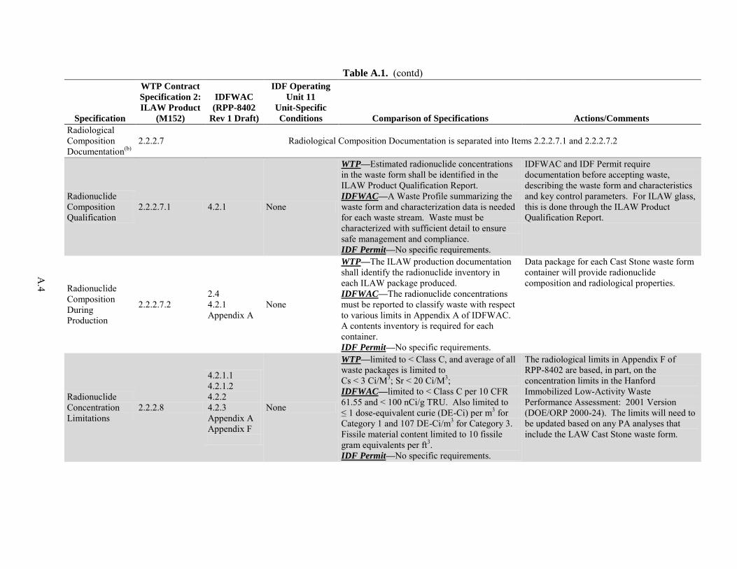
A
.4
Table A.1. (contd)
Specification
WTP Contract
Specification 2:
ILAW Product
(M152)
IDFWAC
(RPP-8402
Rev 1 Draft)
IDF Operating
Unit 11
Unit-Specific
Conditions Comparison of Specifications Actions/Comments
Radiological Composition Documentation(b)
2.2.2.7 Radiological Composition Documentation is separated into Items 2.2.2.7.1 and 2.2.2.7.2
Radionuclide Composition Qualification
2.2.2.7.1 4.2.1 None
WTP—Estimated radionuclide concentrations in the waste form shall be identified in the ILAW Product Qualification Report. IDFWAC—A Waste Profile summarizing the waste form and characterization data is needed for each waste stream. Waste must be characterized with sufficient detail to ensure safe management and compliance. IDF Permit—No specific requirements.
IDFWAC and IDF Permit require documentation before accepting waste, describing the waste form and characteristics and key control parameters. For ILAW glass, this is done through the ILAW Product Qualification Report.
Radionuclide Composition During Production
2.2.2.7.2 2.4 4.2.1 Appendix A
None
WTP—The ILAW production documentation shall identify the radionuclide inventory in each ILAW package produced. IDFWAC—The radionuclide concentrations must be reported to classify waste with respect to various limits in Appendix A of IDFWAC. A contents inventory is required for each container. IDF Permit—No specific requirements.
Data package for each Cast Stone waste form container will provide radionuclide composition and radiological properties.
Radionuclide Concentration Limitations
2.2.2.8
4.2.1.1 4.2.1.2 4.2.2 4.2.3 Appendix A Appendix F
None
WTP—limited to < Class C, and average of all waste packages is limited to Cs < 3 Ci/M3; Sr < 20 Ci/M3; IDFWAC—limited to < Class C per 10 CFR 61.55 and < 100 nCi/g TRU. Also limited to ≤ 1 dose-equivalent curie (DE-Ci) per m3 for Category 1 and 107 DE-Ci/m3 for Category 3. Fissile material content limited to 10 fissile gram equivalents per ft3. IDF Permit—No specific requirements.
The radiological limits in Appendix F of RPP-8402 are based, in part, on the concentration limits in the Hanford Immobilized Low-Activity Waste Performance Assessment: 2001 Version (DOE/ORP 2000-24). The limits will need to be updated based on any PA analyses that include the LAW Cast Stone waste form.
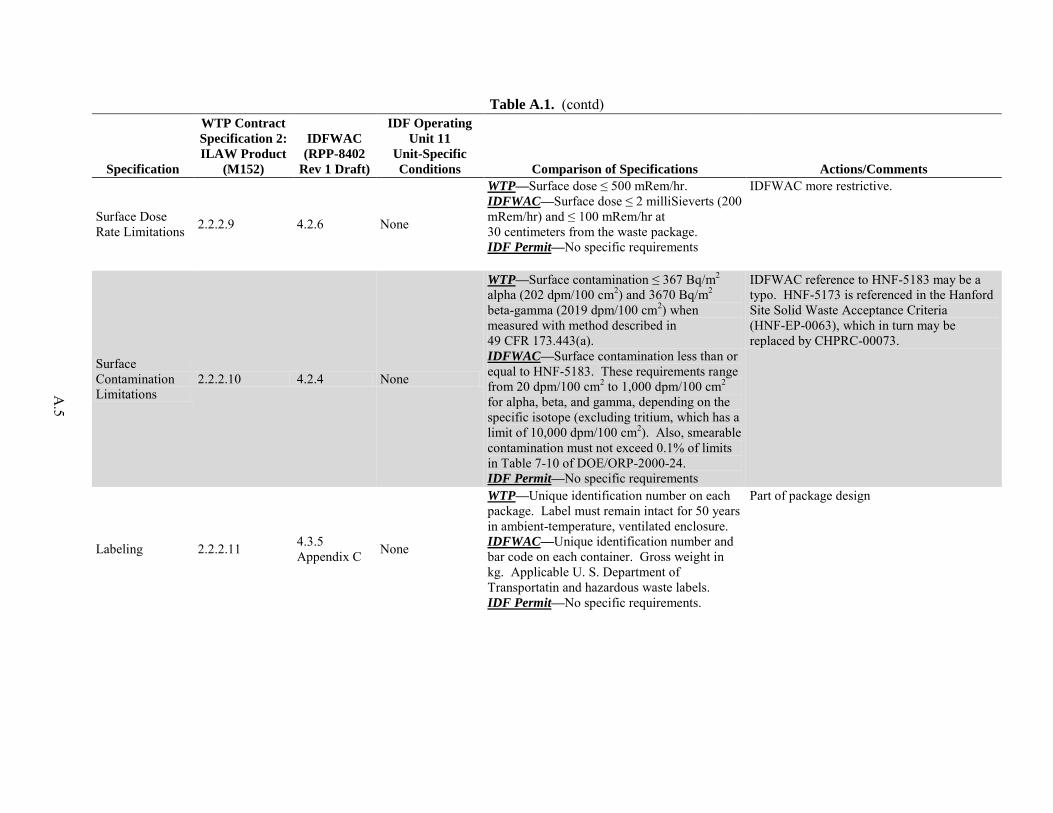
A
.5
Table A.1. (contd)
Specification
WTP Contract
Specification 2:
ILAW Product
(M152)
IDFWAC
(RPP-8402
Rev 1 Draft)
IDF Operating
Unit 11
Unit-Specific
Conditions Comparison of Specifications Actions/Comments
Surface Dose Rate Limitations 2.2.2.9 4.2.6 None
WTP—Surface dose ≤ 500 mRem/hr. IDFWAC—Surface dose ≤ 2 milliSieverts (200 mRem/hr) and ≤ 100 mRem/hr at 30 centimeters from the waste package. IDF Permit—No specific requirements
IDFWAC more restrictive.
Surface Contamination Limitations
2.2.2.10 4.2.4 None
WTP—Surface contamination ≤ 367 Bq/m2 alpha (202 dpm/100 cm2) and 3670 Bq/m2 beta-gamma (2019 dpm/100 cm2) when measured with method described in 49 CFR 173.443(a). IDFWAC—Surface contamination less than or equal to HNF-5183. These requirements range from 20 dpm/100 cm2 to 1,000 dpm/100 cm2
for alpha, beta, and gamma, depending on the specific isotope (excluding tritium, which has a limit of 10,000 dpm/100 cm2). Also, smearable contamination must not exceed 0.1% of limits in Table 7-10 of DOE/ORP-2000-24. IDF Permit—No specific requirements
IDFWAC reference to HNF-5183 may be a typo. HNF-5173 is referenced in the Hanford Site Solid Waste Acceptance Criteria (HNF-EP-0063), which in turn may be replaced by CHPRC-00073.
Labeling 2.2.2.11 4.3.5 Appendix C None
WTP—Unique identification number on each package. Label must remain intact for 50 years in ambient-temperature, ventilated enclosure. IDFWAC—Unique identification number and bar code on each container. Gross weight in kg. Applicable U. S. Department of Transportatin and hazardous waste labels. IDF Permit—No specific requirements.
Part of package design
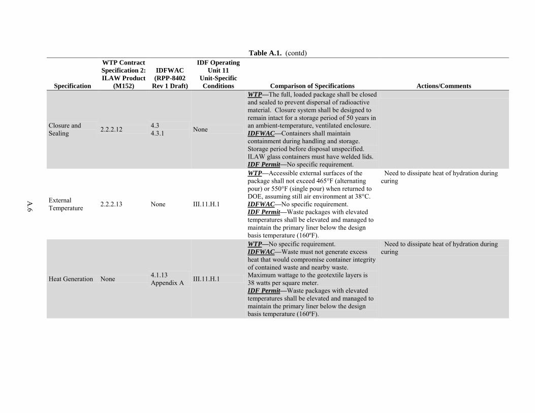
A
.6
Table A.1. (contd)
Specification
WTP Contract
Specification 2:
ILAW Product
(M152)
IDFWAC
(RPP-8402
Rev 1 Draft)
IDF Operating
Unit 11
Unit-Specific
Conditions Comparison of Specifications Actions/Comments
Closure and Sealing 2.2.2.12 4.3
4.3.1 None
WTP—The full, loaded package shall be closed and sealed to prevent dispersal of radioactive material. Closure system shall be designed to remain intact for a storage period of 50 years in an ambient-temperature, ventilated enclosure. IDFWAC—Containers shall maintain containment during handling and storage. Storage period before disposal unspecified. ILAW glass containers must have welded lids. IDF Permit—No specific requirement.
External Temperature 2.2.2.13 None III.11.H.1
WTP—Accessible external surfaces of the package shall not exceed 465°F (alternating pour) or 550°F (single pour) when returned to DOE, assuming still air environment at 38°C. IDFWAC—No specific requirement. IDF Permit—Waste packages with elevated temperatures shall be elevated and managed to maintain the primary liner below the design basis temperature (160ºF).
Need to dissipate heat of hydration during curing
Heat Generation None 4.1.13 Appendix A III.11.H.1
WTP—No specific requirement. IDFWAC—Waste must not generate excess heat that would compromise container integrity of contained waste and nearby waste. Maximum wattage to the geotextile layers is 38 watts per square meter. IDF Permit—Waste packages with elevated temperatures shall be elevated and managed to maintain the primary liner below the design basis temperature (160ºF).
Need to dissipate heat of hydration during curing
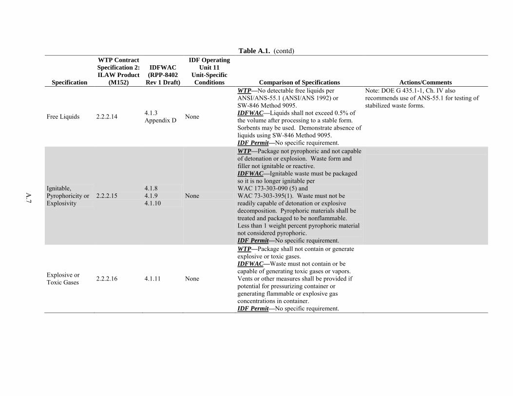
A
.7
Table A.1. (contd)
Specification
WTP Contract
Specification 2:
ILAW Product
(M152)
IDFWAC
(RPP-8402
Rev 1 Draft)
IDF Operating
Unit 11
Unit-Specific
Conditions Comparison of Specifications Actions/Comments
Free Liquids 2.2.2.14 4.1.3 Appendix D None
WTP—No detectable free liquids per ANSI/ANS-55.1 (ANSI/ANS 1992) or SW-846 Method 9095. IDFWAC—Liquids shall not exceed 0.5% of the volume after processing to a stable form. Sorbents may be used. Demonstrate absence of liquids using SW-846 Method 9095. IDF Permit—No specific requirement.
Note: DOE G 435.1-1, Ch. IV also recommends use of ANS-55.1 for testing of stabilized waste forms.
Ignitable, Pyrophoricity or Explosivity
2.2.2.15 4.1.8 4.1.9 4.1.10
None
WTP—Package not pyrophoric and not capable of detonation or explosion. Waste form and filler not ignitable or reactive. IDFWAC—Ignitable waste must be packaged so it is no longer ignitable per WAC 173-303-090 (5) and WAC 73-303-395(1). Waste must not be readily capable of detonation or explosive decomposition. Pyrophoric materials shall be treated and packaged to be nonflammable. Less than 1 weight percent pyrophoric material not considered pyrophoric. IDF Permit—No specific requirement.
Explosive or Toxic Gases 2.2.2.16 4.1.11 None
WTP—Package shall not contain or generate explosive or toxic gases. IDFWAC—Waste must not contain or be capable of generating toxic gases or vapors. Vents or other measures shall be provided if potential for pressurizing container or generating flammable or explosive gas concentrations in container. IDF Permit—No specific requirement.
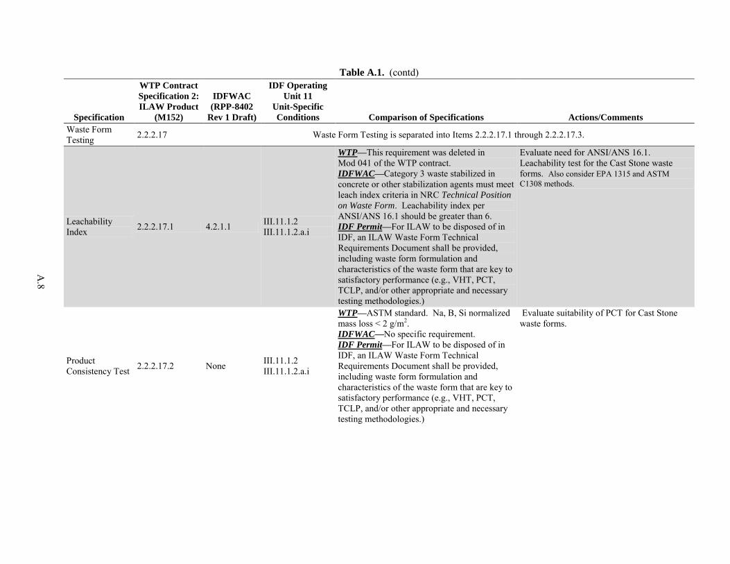
A
.8
Table A.1. (contd)
Specification
WTP Contract
Specification 2:
ILAW Product
(M152)
IDFWAC
(RPP-8402
Rev 1 Draft)
IDF Operating
Unit 11
Unit-Specific
Conditions Comparison of Specifications Actions/Comments
Waste Form Testing 2.2.2.17 Waste Form Testing is separated into Items 2.2.2.17.1 through 2.2.2.17.3.
Leachability Index 2.2.2.17.1 4.2.1.1 III.11.1.2
III.11.1.2.a.i
WTP—This requirement was deleted in Mod 041 of the WTP contract. IDFWAC—Category 3 waste stabilized in concrete or other stabilization agents must meet leach index criteria in NRC Technical Position
on Waste Form. Leachability index per ANSI/ANS 16.1 should be greater than 6. IDF Permit—For ILAW to be disposed of in IDF, an ILAW Waste Form Technical Requirements Document shall be provided, including waste form formulation and characteristics of the waste form that are key to satisfactory performance (e.g., VHT, PCT, TCLP, and/or other appropriate and necessary testing methodologies.)
Evaluate need for ANSI/ANS 16.1. Leachability test for the Cast Stone waste forms. Also consider EPA 1315 and ASTM C1308 methods.
Product Consistency Test 2.2.2.17.2 None III.11.1.2
III.11.1.2.a.i
WTP—ASTM standard. Na, B, Si normalized mass loss < 2 g/m2. IDFWAC—No specific requirement. IDF Permit—For ILAW to be disposed of in IDF, an ILAW Waste Form Technical Requirements Document shall be provided, including waste form formulation and characteristics of the waste form that are key to satisfactory performance (e.g., VHT, PCT, TCLP, and/or other appropriate and necessary testing methodologies.)
Evaluate suitability of PCT for Cast Stone waste forms.
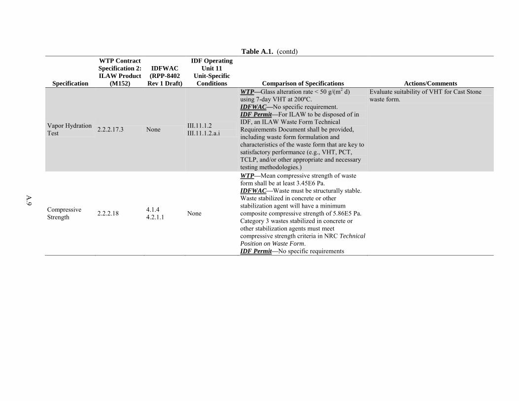
A
.9
Table A.1. (contd)
Specification
WTP Contract
Specification 2:
ILAW Product
(M152)
IDFWAC
(RPP-8402
Rev 1 Draft)
IDF Operating
Unit 11
Unit-Specific
Conditions Comparison of Specifications Actions/Comments
Vapor Hydration Test 2.2.2.17.3 None III.11.1.2
III.11.1.2.a.i
WTP—Glass alteration rate < 50 g/(m2 d) using 7-day VHT at 200ºC. IDFWAC—No specific requirement. IDF Permit—For ILAW to be disposed of in IDF, an ILAW Waste Form Technical Requirements Document shall be provided, including waste form formulation and characteristics of the waste form that are key to satisfactory performance (e.g., VHT, PCT, TCLP, and/or other appropriate and necessary testing methodologies.)
Evaluate suitability of VHT for Cast Stone waste form.
Compressive Strength 2.2.2.18 4.1.4
4.2.1.1 None
WTP—Mean compressive strength of waste form shall be at least 3.45E6 Pa. IDFWAC—Waste must be structurally stable. Waste stabilized in concrete or other stabilization agent will have a minimum composite compressive strength of 5.86E5 Pa. Category 3 wastes stabilized in concrete or other stabilization agents must meet compressive strength criteria in NRC Technical
Position on Waste Form. IDF Permit—No specific requirements
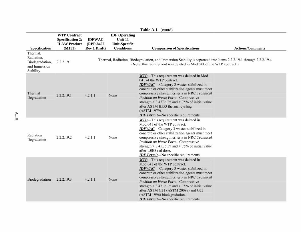
A
.10
Table A.1. (contd)
Specification
WTP Contract
Specification 2:
ILAW Product
(M152)
IDFWAC
(RPP-8402
Rev 1 Draft)
IDF Operating
Unit 11
Unit-Specific
Conditions Comparison of Specifications Actions/Comments
Thermal, Radiation, Biodegradation, and Immersion Stability
2.2.2.19 Thermal, Radiation, Biodegradation, and Immersion Stability is separated into Items 2.2.2.19.1 through 2.2.2.19.4 (Note: this requirement was deleted in Mod 041 of the WTP contract.)
Thermal Degradation 2.2.2.19.1 4.2.1.1 None
WTP—This requirement was deleted in Mod 041 of the WTP contract. IDFWAC— Category 3 wastes stabilized in concrete or other stabilization agents must meet compressive strength criteria in NRC Technical
Position on Waste Form. Compressive strength > 3.45E6 Pa and > 75% of initial value after ASTM B553 thermal cycling (ASTM 1979). IDF Permit—No specific requirements.
Radiation Degradation 2.2.2.19.2 4.2.1.1 None
WTP—This requirement was deleted in Mod 041 of the WTP contract. IDFWAC—Category 3 wastes stabilized in concrete or other stabilization agents must meet compressive strength criteria in NRC Technical
Position on Waste Form. Compressive strength > 3.45E6 Pa and > 75% of initial value after 1.0E8 rad dose. IDF Permit—No specific requirements.
Biodegradation 2.2.2.19.3 4.2.1.1 None
WTP—This requirement was deleted in Mod 041 of the WTP contract. IDFWAC— Category 3 wastes stabilized in concrete or other stabilization agents must meet compressive strength criteria in NRC Technical
Position on Waste Form. Compressive strength > 3.45E6 Pa and > 75% of initial value after ASTM G21 (ASTM 2009a) and G22 (ASTM 1996) biodegradation. IDF Permit—No specific requirements.
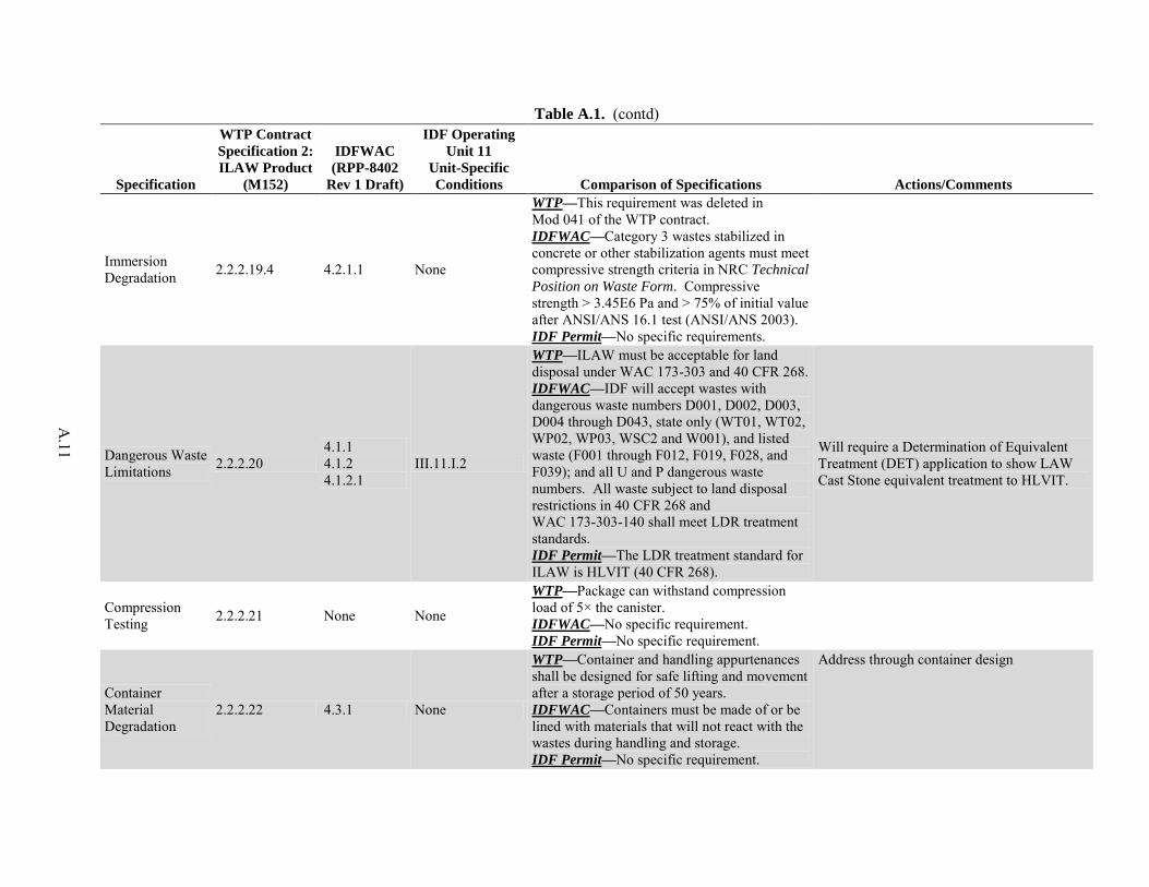
A
.11
Table A.1. (contd)
Specification
WTP Contract
Specification 2:
ILAW Product
(M152)
IDFWAC
(RPP-8402
Rev 1 Draft)
IDF Operating
Unit 11
Unit-Specific
Conditions Comparison of Specifications Actions/Comments
Immersion Degradation 2.2.2.19.4 4.2.1.1 None
WTP—This requirement was deleted in Mod 041 of the WTP contract. IDFWAC—Category 3 wastes stabilized in concrete or other stabilization agents must meet compressive strength criteria in NRC Technical
Position on Waste Form. Compressive strength > 3.45E6 Pa and > 75% of initial value after ANSI/ANS 16.1 test (ANSI/ANS 2003). IDF Permit—No specific requirements.
Dangerous Waste Limitations 2.2.2.20
4.1.1 4.1.2 4.1.2.1
III.11.I.2
WTP—ILAW must be acceptable for land disposal under WAC 173-303 and 40 CFR 268. IDFWAC—IDF will accept wastes with dangerous waste numbers D001, D002, D003, D004 through D043, state only (WT01, WT02, WP02, WP03, WSC2 and W001), and listed waste (F001 through F012, F019, F028, and F039); and all U and P dangerous waste numbers. All waste subject to land disposal restrictions in 40 CFR 268 and WAC 173-303-140 shall meet LDR treatment standards. IDF Permit—The LDR treatment standard for ILAW is HLVIT (40 CFR 268).
Will require a Determination of Equivalent Treatment (DET) application to show LAW Cast Stone equivalent treatment to HLVIT.
Compression Testing 2.2.2.21 None None
WTP—Package can withstand compression load of 5× the canister. IDFWAC—No specific requirement. IDF Permit—No specific requirement.
Container Material Degradation
2.2.2.22 4.3.1 None
WTP—Container and handling appurtenances shall be designed for safe lifting and movement after a storage period of 50 years. IDFWAC—Containers must be made of or be lined with materials that will not react with the wastes during handling and storage. IDF Permit—No specific requirement.
Address through container design
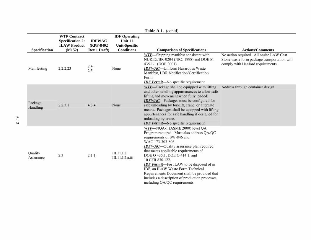
A
.12
Table A.1. (contd)
Specification
WTP Contract
Specification 2:
ILAW Product
(M152)
IDFWAC
(RPP-8402
Rev 1 Draft)
IDF Operating
Unit 11
Unit-Specific
Conditions Comparison of Specifications Actions/Comments
Manifesting 2.2.2.23 2.4 2.5 None
WTP—Shipping manifest consistent with NUREG/BR-0204 (NRC 1998) and DOE M 435.1-1 (DOE 2001). IDFWAC—Uniform Hazardous Waste Manifest, LDR Notification/Certification Form. IDF Permit—No specific requirement.
No action required. All onsite LAW Cast Stone waste form package transportation will comply with Hanford requirements.
Package Handling 2.2.3.1 4.3.4 None
WTP—Package shall be equipped with lifting and other handling appurtenances to allow safe lifting and movement when fully loaded. IDFWAC—Packages must be configured for safe unloading by forklift, crane, or alternate means. Packages shall be equipped with lifting appurtenances for safe handling if designed for unloading by crane. IDF Permit—No specific requirement.
Address through container design
Quality Assurance 2.3 2.1.1 III.11.I.2
III.11.I.2.a.iii
WTP—NQA-1 (ASME 2000) level QA Program required. Must also address QA/QC requirements of SW-846 and WAC 173-303-806. IDFWAC—Quality assurance plan required that meets applicable requirements of DOE O 435.1, DOE O 414.1, and 10 CFR 830.122. IDF Permit—For ILAW to be disposed of in IDF, an ILAW Waste Form Technical Requirements Document shall be provided that includes a description of production processes, including QA/QC requirements.
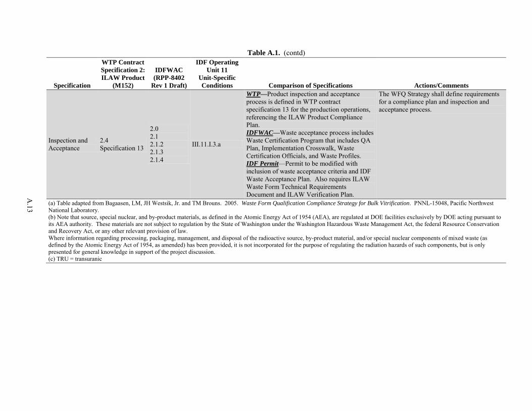
A
.13
Table A.1. (contd)
Specification
WTP Contract
Specification 2:
ILAW Product
(M152)
IDFWAC
(RPP-8402
Rev 1 Draft)
IDF Operating
Unit 11
Unit-Specific
Conditions Comparison of Specifications Actions/Comments
Inspection and Acceptance
2.4 Specification 13
2.0 2.1 2.1.2 2.1.3 2.1.4
III.11.I.3.a
WTP—Product inspection and acceptance process is defined in WTP contract specification 13 for the production operations, referencing the ILAW Product Compliance Plan. IDFWAC—Waste acceptance process includes Waste Certification Program that includes QA Plan, Implementation Crosswalk, Waste Certification Officials, and Waste Profiles. IDF Permit—Permit to be modified with inclusion of waste acceptance criteria and IDF Waste Acceptance Plan. Also requires ILAW Waste Form Technical Requirements Document and ILAW Verification Plan.
The WFQ Strategy shall define requirements for a compliance plan and inspection and acceptance process.
(a) Table adapted from Bagaasen, LM, JH Westsik, Jr. and TM Brouns. 2005. Waste Form Qualification Compliance Strategy for Bulk Vitrification. PNNL-15048, Pacific Northwest National Laboratory. (b) Note that source, special nuclear, and by-product materials, as defined in the Atomic Energy Act of 1954 (AEA), are regulated at DOE facilities exclusively by DOE acting pursuant to its AEA authority. These materials are not subject to regulation by the State of Washington under the Washington Hazardous Waste Management Act, the federal Resource Conservation and Recovery Act, or any other relevant provision of law. Where information regarding processing, packaging, management, and disposal of the radioactive source, by-product material, and/or special nuclear components of mixed waste (as defined by the Atomic Energy Act of 1954, as amended) has been provided, it is not incorporated for the purpose of regulating the radiation hazards of such components, but is only presented for general knowledge in support of the project discussion. (c) TRU = transuranic
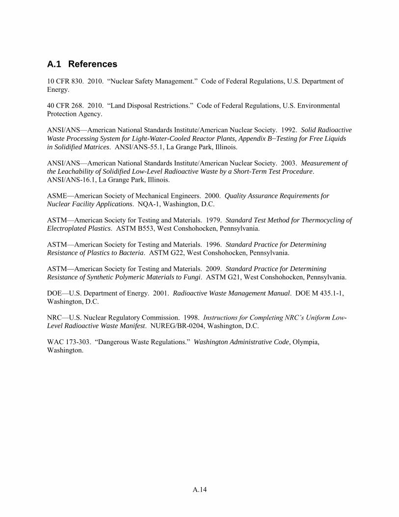
A.14
A.1 References
10 CFR 830. 2010. “Nuclear Safety Management.” Code of Federal Regulations, U.S. Department of Energy.
40 CFR 268. 2010. “Land Disposal Restrictions.” Code of Federal Regulations, U.S. Environmental Protection Agency.
ANSI/ANS—American National Standards Institute/American Nuclear Society. 1992. Solid Radioactive
Waste Processing System for Light-Water-Cooled Reactor Plants, Appendix B—Testing for Free Liquids
in Solidified Matrices. ANSI/ANS-55.1, La Grange Park, Illinois.
ANSI/ANS—American National Standards Institute/American Nuclear Society. 2003. Measurement of
the Leachability of Solidified Low-Level Radioactive Waste by a Short-Term Test Procedure. ANSI/ANS-16.1, La Grange Park, Illinois.
ASME—American Society of Mechanical Engineers. 2000. Quality Assurance Requirements for
Nuclear Facility Applications. NQA-1, Washington, D.C.
ASTM—American Society for Testing and Materials. 1979. Standard Test Method for Thermocycling of
Electroplated Plastics. ASTM B553, West Conshohocken, Pennsylvania.
ASTM—American Society for Testing and Materials. 1996. Standard Practice for Determining
Resistance of Plastics to Bacteria. ASTM G22, West Conshohocken, Pennsylvania.
ASTM—American Society for Testing and Materials. 2009. Standard Practice for Determining
Resistance of Synthetic Polymeric Materials to Fungi. ASTM G21, West Conshohocken, Pennsylvania.
DOE—U.S. Department of Energy. 2001. Radioactive Waste Management Manual. DOE M 435.1-1, Washington, D.C.
NRC—U.S. Nuclear Regulatory Commission. 1998. Instructions for Completing NRC’s Uniform Low-
Level Radioactive Waste Manifest. NUREG/BR-0204, Washington, D.C.
WAC 173-303. “Dangerous Waste Regulations.” Washington Administrative Code, Olympia, Washington.
Appendix B
Cast Stone Waste Form Testing Objectives and Approach Matrix

B.1
Appendix B - Cast Stone Waste Form Testing Objectives and
Approach Matrix
Table B.1 shows the objectives of the Cast Stone test program as outlined in Section 3 of this Secondary Waste Form Qualification Testing Plan. A separate testing plan has been prepared for the Cast Stone process development work6. In several cases, the testing objectives in the program plan are further defined to aid in defining the work scope as follows:
Provide for Acceptance of Waste Form at Integrated Disposal Facility
– 1.0 Provide for Acceptance of Waste Form at IDF
– 14.0 Provide Data to Meet Land Disposal Restrictions Requirements
Optimize Waste Loading
– 2.0 Optimize Waste Loading
Demonstrate Waste Form Over Expected Range of Wastes
– 3.0 Demonstrate Waste Form Over Expected Range of Wastes
Define and Demonstrate Product Control Strategy
– 4.0 Cast Stone Waste Immobilization
Provide Data to Support Risk and Performance Assessments
– 7.0 Solid-Phase Characterization
– 8.0 Waste Form Leach Testing
– 9.0 Waste Package Release Testing
– 10.0 Physical Stability
– 11.0 Waste Form Release Model
– 12.0 Batch Adsorption Tests
– 13.0 Validate PA Predictions
The Requirements column in Table B.1 describes the information needed to address the testing objective.
The next three columns in Table B.1 indicate how the ETF treated wastes should be represented in the testing to address the objective and information requirements. Most of the WFQ testing can be conducted with nonradioactive simulants. Some test objectives require some sort of demonstration that the Cast Stone process/waste form is applicable to the entire range of expected waste compositions. Other tests may require only selected representative simulants that highlight or emphasize specific characteristics of the waste that impact the Cast Stone process/waste form. Testing to address LDRs for the hazardous constituents in the waste, including the RCRA metals and underlying hazardous constituents and
6 Ashley, T. 2012. Cast Stone Engineering Test Plan for Secondary Waste Treatment Project (T3W08), RPP-Plan-51770, Rev. B, ARES Corporation for Washington River Protection Solutions, LLC, Richland, Washington.
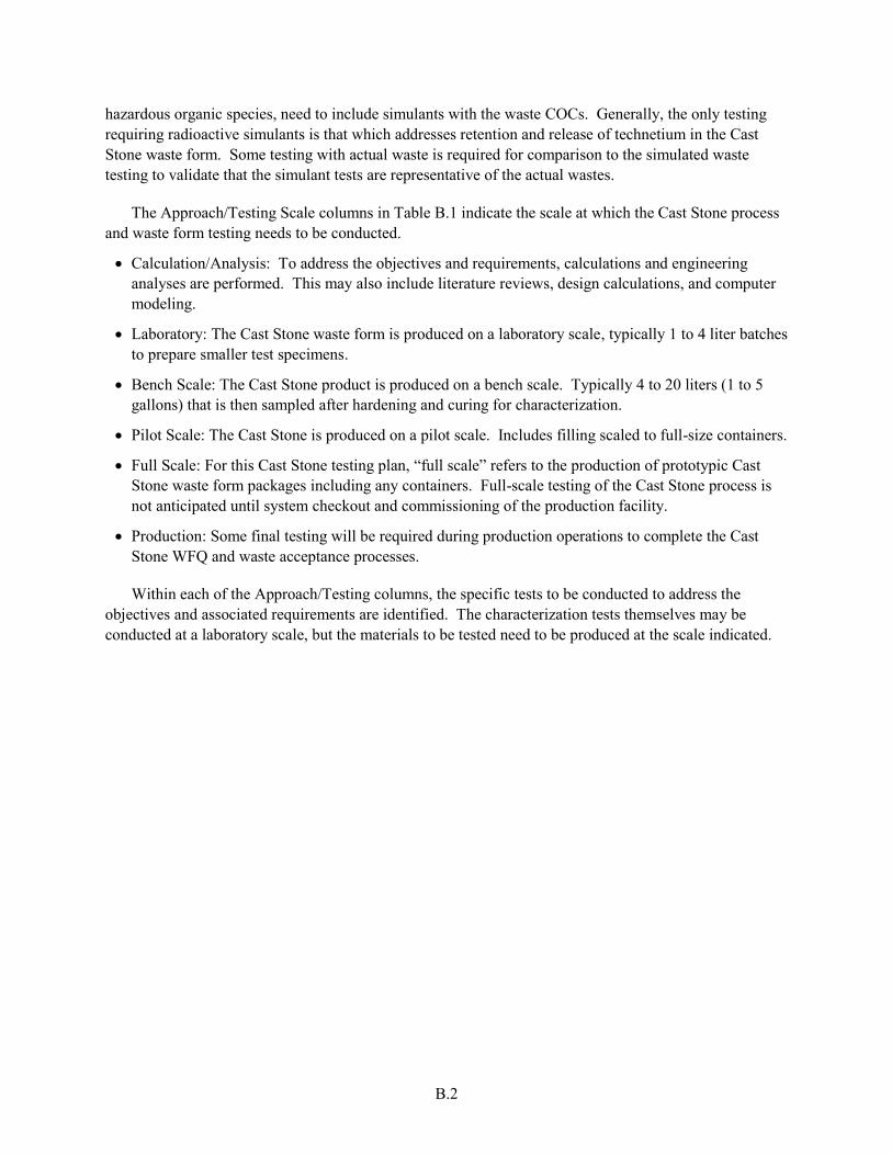
B.2
hazardous organic species, need to include simulants with the waste COCs. Generally, the only testing requiring radioactive simulants is that which addresses retention and release of technetium in the Cast Stone waste form. Some testing with actual waste is required for comparison to the simulated waste testing to validate that the simulant tests are representative of the actual wastes.
The Approach/Testing Scale columns in Table B.1 indicate the scale at which the Cast Stone process and waste form testing needs to be conducted.
Calculation/Analysis: To address the objectives and requirements, calculations and engineering analyses are performed. This may also include literature reviews, design calculations, and computer modeling.
Laboratory: The Cast Stone waste form is produced on a laboratory scale, typically 1 to 4 liter batches to prepare smaller test specimens.
Bench Scale: The Cast Stone product is produced on a bench scale. Typically 4 to 20 liters (1 to 5 gallons) that is then sampled after hardening and curing for characterization.
Pilot Scale: The Cast Stone is produced on a pilot scale. Includes filling scaled to full-size containers.
Full Scale: For this Cast Stone testing plan, “full scale” refers to the production of prototypic Cast Stone waste form packages including any containers. Full-scale testing of the Cast Stone process is not anticipated until system checkout and commissioning of the production facility.
Production: Some final testing will be required during production operations to complete the Cast Stone WFQ and waste acceptance processes.
Within each of the Approach/Testing columns, the specific tests to be conducted to address the objectives and associated requirements are identified. The characterization tests themselves may be conducted at a laboratory scale, but the materials to be tested need to be produced at the scale indicated.
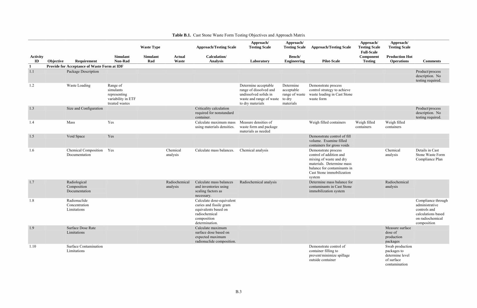
B.3
Table B.1. Cast Stone Waste Form Testing Objectives and Approach Matrix
Activity
ID Objective Requirement
Waste Type Approach/Testing Scale
Approach/
Testing Scale
Approach/
Testing Scale Approach/Testing Scale
Approach/
Testing Scale
Approach/
Testing Scale
Comments
Simulant
Non-Rad
Simulant
Rad
Actual
Waste
Calculation/
Analysis Laboratory
Bench/
Engineering Pilot-Scale
Full-Scale
Component
Testing
Production Hot
Operations
1 Provide for Acceptance of Waste Form at IDF 1.1 Package Description Product/process
description. No testing required.
1.2 Waste Loading Range of simulants representing variability in ETF treated wastes
Determine acceptable range of dissolved and undissolved solids in waste and range of waste to dry materials
Determine acceptable range of waste to dry materials
Demonstrate process control strategy to achieve waste loading in Cast Stone waste form
1.3 Size and Configuration Criticality calculation required for nonstandard container.
Product/process description. No testing required.
1.4 Mass Yes Calculate maximum mass using materials densities.
Measure densities of waste form and package materials as needed
Weigh filled containers Weigh filled containers
Weigh filled containers
1.5 Void Space Yes Demonstrate control of fill volume. Examine filled containers for gross voids
1.6 Chemical Composition Documentation
Yes Chemical analysis
Calculate mass balances. Chemical analysis Demonstrate process control of addition and mixing of waste and dry materials. Determine mass balance for contaminants in Cast Stone immobilization system
Chemical analysis
Details in Cast Stone Waste Form Compliance Plan
1.7 Radiological Composition Documentation
Radiochemical analysis
Calculate mass balances and inventories using scaling factors as necessary.
Radiochemical analysis Determine mass balance for contaminants in Cast Stone immobilization system
Radiochemical analysis
1.8 Radionuclide Concentration Limitations
Calculate dose-equivalent curies and fissile gram equivalents based on radiochemical composition determination.
Compliance through administrative controls and calculations based on radiochemical composition
1.9 Surface Dose Rate Limitations
Calculate maximum surface dose based on expected maximum radionuclide composition.
Measure surface dose of production packages
1.10 Surface Contamination Limitations
Demonstrate control of container filling to prevent/minimize spillage outside container
Swab production packages to determine level of surface contamination
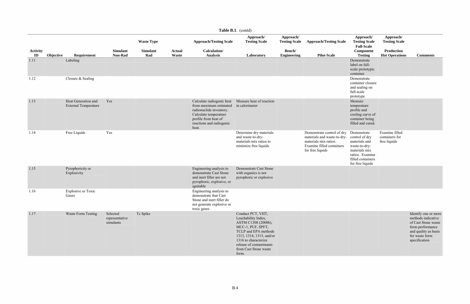
B.4
Table B.1. (contd)
Waste Type Approach/Testing Scale
Approach/
Testing Scale
Approach/
Testing Scale Approach/Testing Scale
Approach/
Testing Scale
Approach/
Testing Scale
Activity
ID Objective Requirement
Simulant
Non-Rad
Simulant
Rad
Actual
Waste
Calculation/
Analysis Laboratory
Bench/
Engineering Pilot-Scale
Full-Scale
Component
Testing
Production
Hot Operations Comments
1.11 Labeling Demonstrate label on full-scale prototypic container
1.12 Closure & Sealing Demonstrate container closure and sealing on full-scale prototype
1.13 Heat Generation and External Temperature
Yes Calculate radiogenic heat from maximum estimated radionuclide inventory. Calculate temperature profile from heat of reactions and radiogenic heat.
Measure heat of reaction in calorimeter
Measure temperature profile and cooling curve of container being filled and cured.
1.14 Free Liquids Yes Determine dry materials and waste-to-dry-materials mix ratios to minimize free liquids
Demonstrate control of dry materials and waste-to-dry-materials mix ratios. Examine filled containers for free liquids
Demonstrate control of dry materials and waste-to-dry-materials mix ratios. Examine filled containers for free liquids
Examine filled containers for free liquids
1.15 Pyrophoricity or Explosivity
Engineering analysis to demonstrate Cast Stone and inert filler are not pyrophoric, explosive, or ignitable
Demonstrate Cast Stone with organics is not pyrophoric or explosive
1.16 Explosive or Toxic Gases
Engineering analysis to demonstrate that Cast Stone and inert filler do not generate explosive or toxic gases
1.17 Waste Form Testing Selected representative simulants
Tc Spike Conduct PCT, VHT, Leachability Index, ASTM C1308 (2008b), MCC-1, PUF, SPFT, TCLP and EPA methods 1313, 1314, 1315, and/or 1316 to characterize release of contaminants from Cast Stone waste form.
Identify one or more methods indicative of Cast Stone waste form performance and quality as basis for waste form specification
B.5
Table B.1. (contd)
Waste Type Approach/Testing Scale
Approach/
Testing Scale
Approach/
Testing Scale Approach/Testing Scale
Approach/
Testing Scale
Approach/
Testing Scale
Activity
ID Objective Requirement
Simulant
Non-Rad
Simulant
Rad
Actual
Waste
Calculation/
Analysis Laboratory
Bench/
Engineering Pilot-Scale
Full-Scale
Component
Testing
Production
Hot Operations Comments
1.18 Leachability Index Selected representative simulants
Tc spike Selected representative actual waste samples
ANSI/ANS16.1 (2003) Leachability Index test on 2-in diameter 4-inch tall Cast Stone waste form cylinders
ANSI/ANS16.1 Leachability Index test on 2-in. diameter 4-in. tall Cast Stone waste form cylinders
1.19 Product Consistency Test
Selected representative simulants
Tc spike Selected representative actual waste samples
PCT per ASTM C1285 (2008a)
PCT per ASTM C1285 PCT as a specification for Cast Stone waste form needs to be evaluated
1.20 Vapor Hydration Test Selected representative simulants
VHT per ASTM C1663 (2009b)
VHT per ASTM C1663 VHT as a specification for Cast Stone waste form needs to be evaluated
1.21 Compressive Strength Selected representative simulants
Measure compressive strength on 2-in diameter 4-in. tall Cast Stone waste form cylinders. ASTM C39/C39M (2009a).
1.22 Thermal, Radiation, Biodegradation, and Immersion Stability
Selected representative simulants
Measure compressive strength (ASTM C39/C39M) on Cast Stone waste form cylinders after thermal cycling (ASTM B553 [1985]), biodegradation (ASTM G21 [2009d], ASTM G22 [1996]), irradiation, and water immersion tests (ANSI/ANS 16.1 [2003])
1.23 Dangerous Waste See Land Disposal Restrictions below
1.24 Compression Testing Conduct engineering calculations to demonstrate compliance with package integrity and handling requirements.
1.25 Container Material Degradation
Conduct engineering calculations to demonstrate compliance with package integrity and handling requirements.
Cast Stone interactions with waste form container studies
Demonstrate container lifting and handling on full-scale prototype.
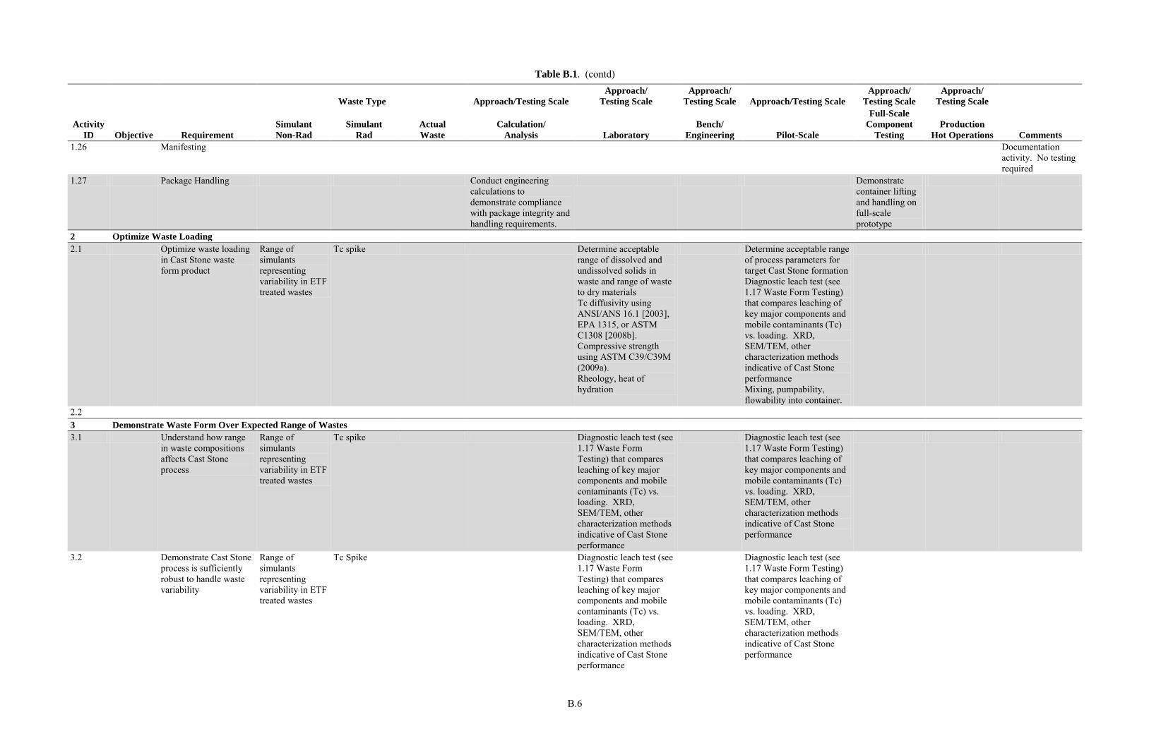
B.6
Table B.1. (contd)
Waste Type Approach/Testing Scale
Approach/
Testing Scale
Approach/
Testing Scale Approach/Testing Scale
Approach/
Testing Scale
Approach/
Testing Scale
Activity
ID Objective Requirement
Simulant
Non-Rad
Simulant
Rad
Actual
Waste
Calculation/
Analysis Laboratory
Bench/
Engineering Pilot-Scale
Full-Scale
Component
Testing
Production
Hot Operations Comments
1.26 Manifesting Documentation activity. No testing required
1.27 Package Handling Conduct engineering calculations to demonstrate compliance with package integrity and handling requirements.
Demonstrate container lifting and handling on full-scale prototype
2 Optimize Waste Loading
2.1 Optimize waste loading in Cast Stone waste form product
Range of simulants representing variability in ETF treated wastes
Tc spike Determine acceptable range of dissolved and undissolved solids in waste and range of waste to dry materials Tc diffusivity using ANSI/ANS 16.1 [2003], EPA 1315, or ASTM C1308 [2008b]. Compressive strength using ASTM C39/C39M (2009a). Rheology, heat of hydration
Determine acceptable range of process parameters for target Cast Stone formation Diagnostic leach test (see 1.17 Waste Form Testing) that compares leaching of key major components and mobile contaminants (Tc) vs. loading. XRD, SEM/TEM, other characterization methods indicative of Cast Stone performance Mixing, pumpability, flowability into container.
2.2 3 Demonstrate Waste Form Over Expected Range of Wastes
3.1 Understand how range in waste compositions affects Cast Stone process
Range of simulants representing variability in ETF treated wastes
Tc spike Diagnostic leach test (see 1.17 Waste Form Testing) that compares leaching of key major components and mobile contaminants (Tc) vs. loading. XRD, SEM/TEM, other characterization methods indicative of Cast Stone performance
Diagnostic leach test (see 1.17 Waste Form Testing) that compares leaching of key major components and mobile contaminants (Tc) vs. loading. XRD, SEM/TEM, other characterization methods indicative of Cast Stone performance
3.2 Demonstrate Cast Stone process is sufficiently robust to handle waste variability
Range of simulants representing variability in ETF treated wastes
Tc Spike Diagnostic leach test (see 1.17 Waste Form Testing) that compares leaching of key major components and mobile contaminants (Tc) vs. loading. XRD, SEM/TEM, other characterization methods indicative of Cast Stone performance
Diagnostic leach test (see 1.17 Waste Form Testing) that compares leaching of key major components and mobile contaminants (Tc) vs. loading. XRD, SEM/TEM, other characterization methods indicative of Cast Stone performance
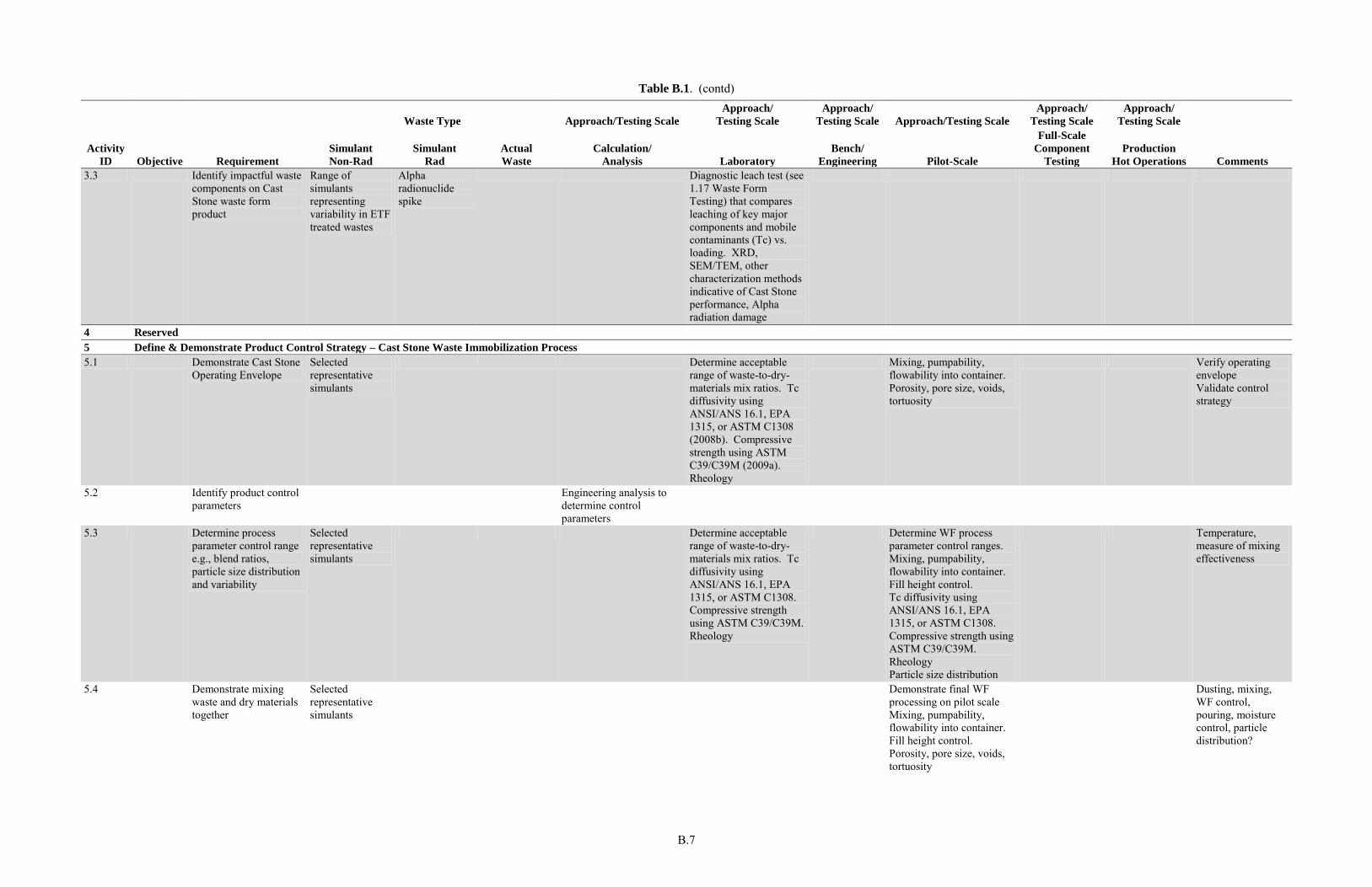
B.7
Table B.1. (contd)
Waste Type Approach/Testing Scale
Approach/
Testing Scale
Approach/
Testing Scale Approach/Testing Scale
Approach/
Testing Scale
Approach/
Testing Scale
Activity
ID Objective Requirement
Simulant
Non-Rad
Simulant
Rad
Actual
Waste
Calculation/
Analysis Laboratory
Bench/
Engineering Pilot-Scale
Full-Scale
Component
Testing
Production
Hot Operations Comments
3.3 Identify impactful waste components on Cast Stone waste form product
Range of simulants representing variability in ETF treated wastes
Alpha radionuclide spike
Diagnostic leach test (see 1.17 Waste Form Testing) that compares leaching of key major components and mobile contaminants (Tc) vs. loading. XRD, SEM/TEM, other characterization methods indicative of Cast Stone performance, Alpha radiation damage
4 Reserved
5 Define & Demonstrate Product Control Strategy – Cast Stone Waste Immobilization Process
5.1 Demonstrate Cast Stone Operating Envelope
Selected representative simulants
Determine acceptable range of waste-to-dry-materials mix ratios. Tc diffusivity using ANSI/ANS 16.1, EPA 1315, or ASTM C1308 (2008b). Compressive strength using ASTM C39/C39M (2009a). Rheology
Mixing, pumpability, flowability into container. Porosity, pore size, voids, tortuosity
Verify operating envelope Validate control strategy
5.2 Identify product control parameters
Engineering analysis to determine control parameters
5.3 Determine process parameter control range e.g., blend ratios, particle size distribution and variability
Selected representative simulants
Determine acceptable range of waste-to-dry-materials mix ratios. Tc diffusivity using ANSI/ANS 16.1, EPA 1315, or ASTM C1308. Compressive strength using ASTM C39/C39M. Rheology
Determine WF process parameter control ranges. Mixing, pumpability, flowability into container. Fill height control. Tc diffusivity using ANSI/ANS 16.1, EPA 1315, or ASTM C1308. Compressive strength using ASTM C39/C39M. Rheology Particle size distribution
Temperature, measure of mixing effectiveness
5.4 Demonstrate mixing waste and dry materials together
Selected representative simulants
Demonstrate final WF processing on pilot scale Mixing, pumpability, flowability into container. Fill height control. Porosity, pore size, voids, tortuosity
Dusting, mixing, WF control, pouring, moisture control, particle distribution?
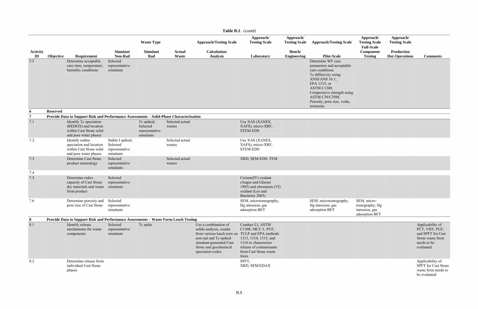
B.8
Table B.1. (contd)
Waste Type Approach/Testing Scale
Approach/
Testing Scale
Approach/
Testing Scale Approach/Testing Scale
Approach/
Testing Scale
Approach/
Testing Scale
Activity
ID Objective Requirement
Simulant
Non-Rad
Simulant
Rad
Actual
Waste
Calculation/
Analysis Laboratory
Bench/
Engineering Pilot-Scale
Full-Scale
Component
Testing
Production
Hot Operations Comments
5.5 Determine acceptable cure time, temperature, humidity conditions
Selected representative simulants
Determine WF cure parameters and acceptable cure conditions Tc diffusivity using ANSI/ANS 16.1, EPA 1315, or ASTM C1308. Compressive strength using ASTM C39/C39M. Porosity, pore size, voids, tortuosity
6 Reserved
7 Provide Data to Support Risk and Performance Assessments – Solid-Phase Characterization
7.1 Identify Tc speciation (REDOX) and location within Cast Stone solid and pore water phases
Tc spiked; Selected representative simulants
Selected actual wastes
Use XAS (XANES, XAFS), micro-XRF, STEM-EDS
7.2 Identify iodine speciation and location within Cast Stone solid and pore water phases
Stable I spiked; Selected representative simulants
Selected actual wastes
Use XAS (XANES, XAFS), micro-XRF, STEM-EDS
7.3 Determine Cast Stone product mineralogy
Selected representative simulants
Selected actual wastes
XRD, SEM-EDS, TEM
7.4 7.5 Determine redox
capacity of Cast Stone dry materials and waste form product
Selected representative simulants
Cerium(IV) oxidant (Angus and Glasser 1985) and chromium (VI) oxidant (Lee and Batchelor 2003)
7.6 Determine porosity and pore size of Cast Stone
Selected representative simulants
SEM, microtomography, Hg intrusion, gas adsorption BET
SEM, microtomography, Hg intrusion, gas adsorption BET
SEM, micro-tomography, Hg intrusion, gas adsorption BET
8 Provide Data to Support Risk and Performance Assessments – Waste Form Leach Testing
8.1 Identify release mechanisms for waste components
Selected representative simulants
Tc spike Use a combination of solids analysis, results from various leach tests on non-rad and Tc-spiked simulant-generated Cast Stone and geochemical speciation codes.
Conduct LI, ASTM C1308, MCC-1, PUF, TCLP and EPA methods 1313, 1314, 1315, and 1316 to characterize release of contaminants from Cast Stone waste form.
Applicability of PCT, VHT, PUF, and SPFT for Cast Stone waste form needs to be evaluated
8.2 Determine release from individual Cast Stone phases
SPFT, XRD, SEM/EDAX
Applicability of SPFT for Cast Stone waste form needs to be evaluated
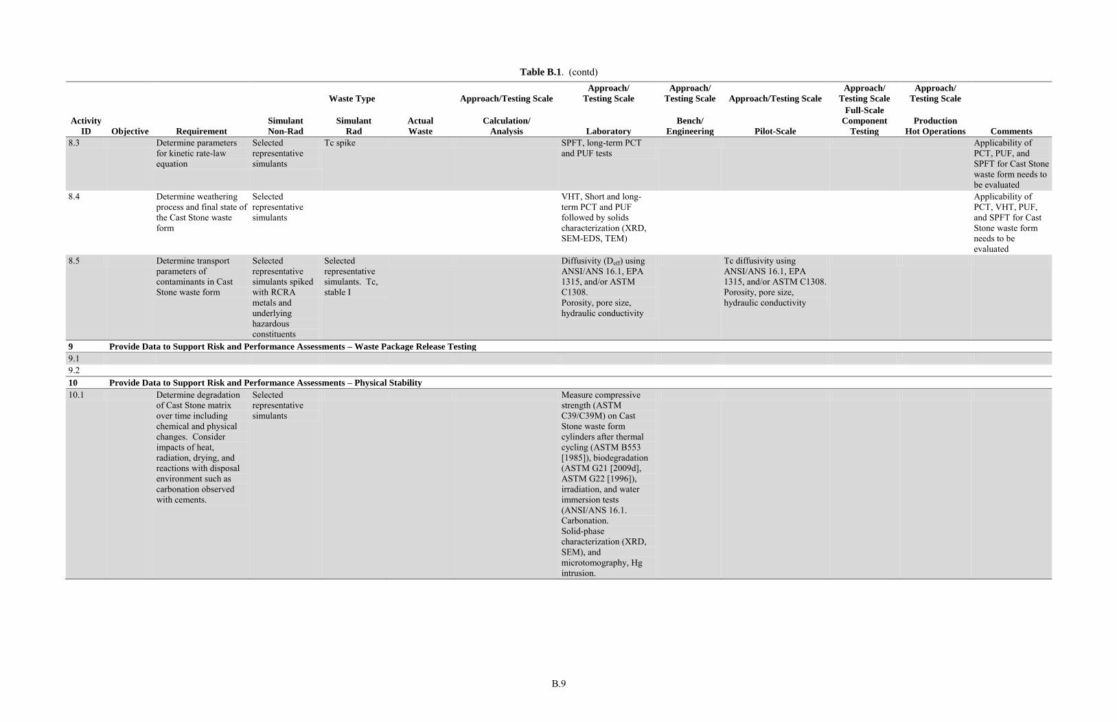
B.9
Table B.1. (contd)
Waste Type Approach/Testing Scale
Approach/
Testing Scale
Approach/
Testing Scale Approach/Testing Scale
Approach/
Testing Scale
Approach/
Testing Scale
Activity
ID Objective Requirement
Simulant
Non-Rad
Simulant
Rad
Actual
Waste
Calculation/
Analysis Laboratory
Bench/
Engineering Pilot-Scale
Full-Scale
Component
Testing
Production
Hot Operations Comments
8.3 Determine parameters for kinetic rate-law equation
Selected representative simulants
Tc spike SPFT, long-term PCT and PUF tests
Applicability of PCT, PUF, and SPFT for Cast Stone waste form needs to be evaluated
8.4 Determine weathering process and final state of the Cast Stone waste form
Selected representative simulants
VHT, Short and long-term PCT and PUF followed by solids characterization (XRD, SEM-EDS, TEM)
Applicability of PCT, VHT, PUF, and SPFT for Cast Stone waste form needs to be evaluated
8.5 Determine transport parameters of contaminants in Cast Stone waste form
Selected representative simulants spiked with RCRA metals and underlying hazardous constituents
Selected representative simulants. Tc, stable I
Diffusivity (Deff) using ANSI/ANS 16.1, EPA 1315, and/or ASTM C1308. Porosity, pore size, hydraulic conductivity
Tc diffusivity using ANSI/ANS 16.1, EPA 1315, and/or ASTM C1308. Porosity, pore size, hydraulic conductivity
9 Provide Data to Support Risk and Performance Assessments – Waste Package Release Testing
9.1 9.2 10 Provide Data to Support Risk and Performance Assessments – Physical Stability
10.1 Determine degradation of Cast Stone matrix over time including chemical and physical changes. Consider impacts of heat, radiation, drying, and reactions with disposal environment such as carbonation observed with cements.
Selected representative simulants
Measure compressive strength (ASTM C39/C39M) on Cast Stone waste form cylinders after thermal cycling (ASTM B553 [1985]), biodegradation (ASTM G21 [2009d], ASTM G22 [1996]), irradiation, and water immersion tests (ANSI/ANS 16.1. Carbonation. Solid-phase characterization (XRD, SEM), and microtomography, Hg intrusion.
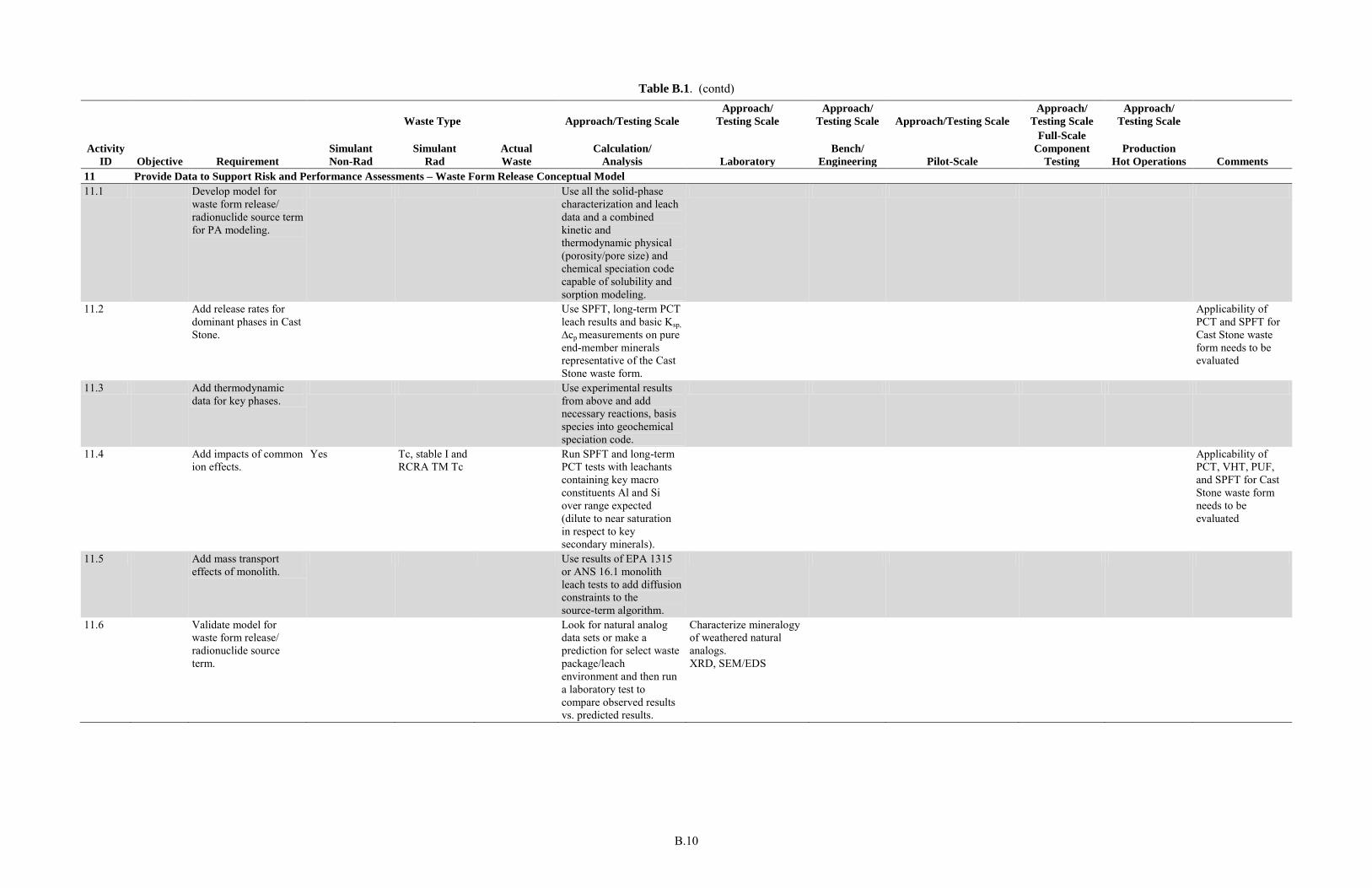
B.10
Table B.1. (contd)
Waste Type Approach/Testing Scale
Approach/
Testing Scale
Approach/
Testing Scale Approach/Testing Scale
Approach/
Testing Scale
Approach/
Testing Scale
Activity
ID Objective Requirement
Simulant
Non-Rad
Simulant
Rad
Actual
Waste
Calculation/
Analysis Laboratory
Bench/
Engineering Pilot-Scale
Full-Scale
Component
Testing
Production
Hot Operations Comments
11 Provide Data to Support Risk and Performance Assessments – Waste Form Release Conceptual Model
11.1 Develop model for waste form release/ radionuclide source term for PA modeling.
Use all the solid-phase characterization and leach data and a combined kinetic and thermodynamic physical (porosity/pore size) and chemical speciation code capable of solubility and sorption modeling.
11.2 Add release rates for dominant phases in Cast Stone.
Use SPFT, long-term PCT leach results and basic Ksp, ∆cp measurements on pure end-member minerals representative of the Cast Stone waste form.
Applicability of PCT and SPFT for Cast Stone waste form needs to be evaluated
11.3 Add thermodynamic data for key phases.
Use experimental results from above and add necessary reactions, basis species into geochemical speciation code.
11.4 Add impacts of common ion effects.
Yes Tc, stable I and RCRA TM Tc
Run SPFT and long-term PCT tests with leachants containing key macro constituents Al and Si over range expected (dilute to near saturation in respect to key secondary minerals).
Applicability of PCT, VHT, PUF, and SPFT for Cast Stone waste form needs to be evaluated
11.5 Add mass transport effects of monolith.
Use results of EPA 1315 or ANS 16.1 monolith leach tests to add diffusion constraints to the source-term algorithm.
11.6 Validate model for waste form release/ radionuclide source term.
Look for natural analog data sets or make a prediction for select waste package/leach environment and then run a laboratory test to compare observed results vs. predicted results.
Characterize mineralogy of weathered natural analogs. XRD, SEM/EDS
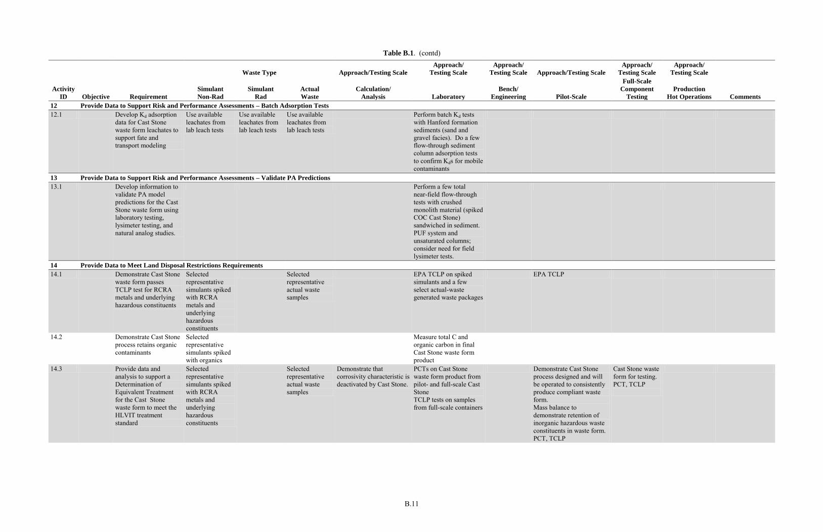
B.11
Table B.1. (contd)
Waste Type Approach/Testing Scale
Approach/
Testing Scale
Approach/
Testing Scale Approach/Testing Scale
Approach/
Testing Scale
Approach/
Testing Scale
Activity
ID Objective Requirement
Simulant
Non-Rad
Simulant
Rad
Actual
Waste
Calculation/
Analysis Laboratory
Bench/
Engineering Pilot-Scale
Full-Scale
Component
Testing
Production
Hot Operations Comments
12 Provide Data to Support Risk and Performance Assessments – Batch Adsorption Tests
12.1 Develop Kd adsorption data for Cast Stone waste form leachates to support fate and transport modeling
Use available leachates from lab leach tests
Use available leachates from lab leach tests
Use available leachates from lab leach tests
Perform batch Kd tests with Hanford formation sediments (sand and gravel facies). Do a few flow-through sediment column adsorption tests to confirm Kds for mobile contaminants
13 Provide Data to Support Risk and Performance Assessments – Validate PA Predictions
13.1 Develop information to validate PA model predictions for the Cast Stone waste form using laboratory testing, lysimeter testing, and natural analog studies.
Perform a few total near-field flow-through tests with crushed monolith material (spiked COC Cast Stone) sandwiched in sediment. PUF system and unsaturated columns; consider need for field lysimeter tests.
14 Provide Data to Meet Land Disposal Restrictions Requirements
14.1 Demonstrate Cast Stone waste form passes TCLP test for RCRA metals and underlying hazardous constituents
Selected representative simulants spiked with RCRA metals and underlying hazardous constituents
Selected representative actual waste samples
EPA TCLP on spiked simulants and a few select actual-waste generated waste packages
EPA TCLP
14.2 Demonstrate Cast Stone process retains organic contaminants
Selected representative simulants spiked with organics
Measure total C and organic carbon in final Cast Stone waste form product
14.3 Provide data and analysis to support a Determination of Equivalent Treatment for the Cast Stone waste form to meet the HLVIT treatment standard
Selected representative simulants spiked with RCRA metals and underlying hazardous constituents
Selected representative actual waste samples
Demonstrate that corrosivity characteristic is deactivated by Cast Stone.
PCTs on Cast Stone waste form product from pilot- and full-scale Cast Stone TCLP tests on samples from full-scale containers
Demonstrate Cast Stone process designed and will be operated to consistently produce compliant waste form. Mass balance to demonstrate retention of inorganic hazardous waste constituents in waste form. PCT, TCLP
Cast Stone waste form for testing. PCT, TCLP
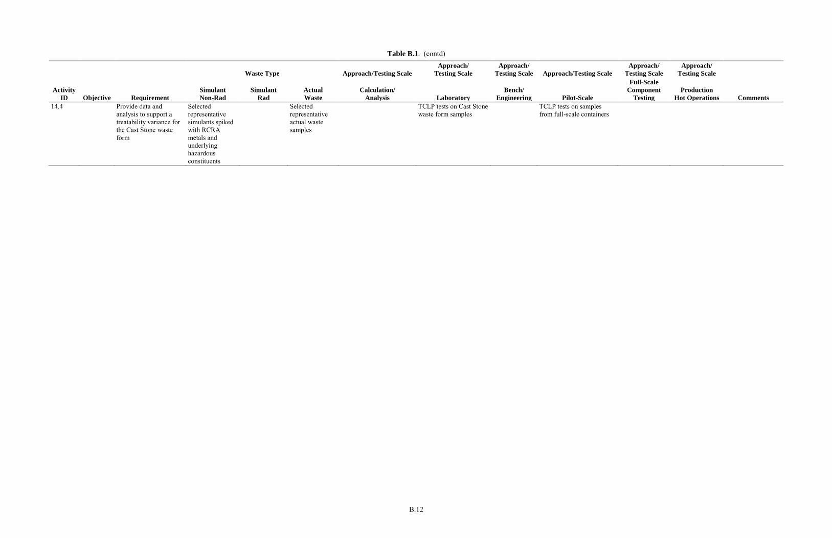
B.12
Table B.1. (contd)
Waste Type Approach/Testing Scale
Approach/
Testing Scale
Approach/
Testing Scale Approach/Testing Scale
Approach/
Testing Scale
Approach/
Testing Scale
Activity
ID Objective Requirement
Simulant
Non-Rad
Simulant
Rad
Actual
Waste
Calculation/
Analysis Laboratory
Bench/
Engineering Pilot-Scale
Full-Scale
Component
Testing
Production
Hot Operations Comments
14.4 Provide data and analysis to support a treatability variance for the Cast Stone waste form
Selected representative simulants spiked with RCRA metals and underlying hazardous constituents
Selected representative actual waste samples
TCLP tests on Cast Stone waste form samples
TCLP tests on samples from full-scale containers
B.13
B.1 References
Angus MJ and FP Glasser. 1985. “The Chemical Environment in Cement Matrices.” Mat. Res. Soc.
Symp. Proc. 50:547–556.
ANSI/ANS—American National Standards Institute/American Nuclear Society. 2003. Measurement of
the Leachability of Solidified Low-Level Radioactive Wastes by a Short Term Test Procedure. ANSI/ANS-16.1, La Grange Park, Illinois.
ASTM—American Society for Testing and Materials. 1985. Standard Test Method for Thermocycling of
Electroplated Plastics. ASTM B553, West Conshohocken, Pennsylvania.
ASTM—American Society for Testing and Materials. 1996. Standard Practice for Determining
Resistance of Plastics to Bacteria. ASTM G22, West Conshohocken, Pennsylvania.
ASTM—American Society for Testing and Materials. 2008a. Standard Test Methods for Determining
Chemical Durability of Nuclear, Hazardous, and Mixed Waste Glasses and Multiphase Glass Ceramics:
The Product Consistency Test (PCT). ASTM C1285, West Conshohocken, Pennsylvania.
ASTM—American Society for Testing and Materials. 2008b. Standard Test Method for Accelerated
Leach Test for Diffusive Releases from Solidified Waste and a Computer Program to Model Diffusive,
Fractional Leaching from Cylindrical Waste Forms. ASTM C1308, West Conshohocken, Pennsylvania.
ASTM—American Society for Testing and Materials. 2009a. Standard Test Method for Compressive
Strength of Cylindrical Concrete Specimens. ASTM C39/C39M, West Conshohocken, Pennsylvania.
ASTM—American Society for Testing and Materials. 2009b. Standard Test Method for Measuring
Waste Glass or Glass Ceramic Durability by Vapor Hydration Test. ASTM C1663, West Conshohocken, Pennsylvania.
ASTM—American Society for Testing and Materials. 2009d. Standard Practice for Determining
Resistance of Synthetic Polymeric Materials to Fungi. ASTM G21, West Conshohocken, Pennsylvania.
EPA—U.S. Environmental Protection Agency. 2009a. Method 1313: Leaching Test (Liquid-Solid
Partitioning as a Function of Extract pH) of Constitutents in Solid Materials using a Parallel Batch
Extraction Test (DRAFT). U.S. Environmental Protection Agency, Washington, D.C.
EPA—U.S. Environmental Protection Agency. 2009b. Method 1314: Leaching Test (Liquid-Solid
Partitioning as a Function of Liquid-Solid Ratio) of Constituents in Solid Materials using an Up-Flow
Perculation Column (DRAFT). U.S. Environmental Protection Agency, Washington, D.C.
EPA—U.S. Environmental Protection Agency. 2009c. Mass Transfer Rates of Constituents in Monolith
or Compacted Granular Materials Using a Semi-Dynamic Tank Leaching Test. Draft Method 1315, Washington, D.C.
EPA—U.S. Environmental Protection Agency. 2009d. Method 1316: Leaching Test (Liquid-Solid
Partitioning as a Function of Liquid-to-Solid Ratio) of Constituents in Solid Materials using a Parallel
Batch Extraction Test (DRAFT). U.S. Environmental Protection Agency, Washington, D.C.

B.14
Lee W and B Batchelor. 2003. “Reductive Capacity of Natural Reductants.” Environmental Science
Technology 37: 535-541.
Appendix C
Cast Stone Test Facilities

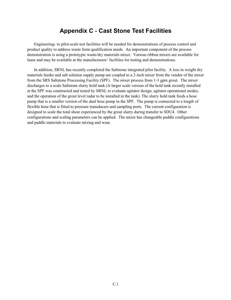
C.1
Appendix C - Cast Stone Test Facilities
Engineering- to pilot-scale test facilities will be needed for demonstrations of process control and product quality to address waste form qualification needs. An important component of the process demonstration is using a prototypic waste/dry materials mixer. Various ribbon mixers are available for lease and may be available at the manufacturers’ facilities for testing and demonstrations.
In addition, SRNL has recently completed the Saltstone integrated pilot facility. A loss in weight dry materials feeder and salt solution supply pump are coupled to a 2-inch mixer from the vendor of the mixer from the SRS Saltstone Processing Facility (SPF). The mixer process from 1-3 gpm grout. The mixer discharges to a scale Saltstone slurry hold tank (A larger scale version of the hold tank recently installed at the SPF was constructed and tested by SRNL to evaluate agitator design, agitator operational modes, and the operation of the grout level radar to be installed in the tank). The slurry hold tank feeds a hose pump that is a smaller version of the dual hose pump in the SPF. The pump is connected to a length of flexible hose that is fitted to pressure transducers and sampling ports. The current configuration is designed to scale the total shear experienced by the grout slurry during transfer to SDU4. Other configurations and scaling parameters can be applied. The mixer has changeable paddle configurations and paddle materials to evaluate mixing and wear.

D.1
Appendix D
Solution and Solid-Phase Analysis Techniques

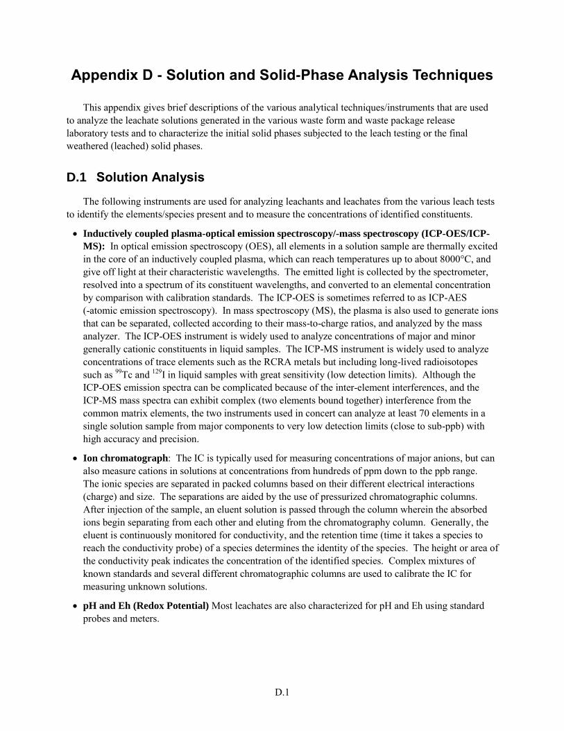
D.1
Appendix D - Solution and Solid-Phase Analysis Techniques
This appendix gives brief descriptions of the various analytical techniques/instruments that are used to analyze the leachate solutions generated in the various waste form and waste package release laboratory tests and to characterize the initial solid phases subjected to the leach testing or the final weathered (leached) solid phases.
D.1 Solution Analysis
The following instruments are used for analyzing leachants and leachates from the various leach tests to identify the elements/species present and to measure the concentrations of identified constituents.
Inductively coupled plasma-optical emission spectroscopy/-mass spectroscopy (ICP-OES/ICP-
MS): In optical emission spectroscopy (OES), all elements in a solution sample are thermally excited in the core of an inductively coupled plasma, which can reach temperatures up to about 8000°C, and give off light at their characteristic wavelengths. The emitted light is collected by the spectrometer, resolved into a spectrum of its constituent wavelengths, and converted to an elemental concentration by comparison with calibration standards. The ICP-OES is sometimes referred to as ICP-AES (-atomic emission spectroscopy). In mass spectroscopy (MS), the plasma is also used to generate ions that can be separated, collected according to their mass-to-charge ratios, and analyzed by the mass analyzer. The ICP-OES instrument is widely used to analyze concentrations of major and minor generally cationic constituents in liquid samples. The ICP-MS instrument is widely used to analyze concentrations of trace elements such as the RCRA metals but including long-lived radioisotopes such as 99Tc and 129I in liquid samples with great sensitivity (low detection limits). Although the ICP-OES emission spectra can be complicated because of the inter-element interferences, and the ICP-MS mass spectra can exhibit complex (two elements bound together) interference from the common matrix elements, the two instruments used in concert can analyze at least 70 elements in a single solution sample from major components to very low detection limits (close to sub-ppb) with high accuracy and precision.
Ion chromatograph: The IC is typically used for measuring concentrations of major anions, but can also measure cations in solutions at concentrations from hundreds of ppm down to the ppb range. The ionic species are separated in packed columns based on their different electrical interactions (charge) and size. The separations are aided by the use of pressurized chromatographic columns. After injection of the sample, an eluent solution is passed through the column wherein the absorbed ions begin separating from each other and eluting from the chromatography column. Generally, the eluent is continuously monitored for conductivity, and the retention time (time it takes a species to reach the conductivity probe) of a species determines the identity of the species. The height or area of the conductivity peak indicates the concentration of the identified species. Complex mixtures of known standards and several different chromatographic columns are used to calibrate the IC for measuring unknown solutions.
pH and Eh (Redox Potential) Most leachates are also characterized for pH and Eh using standard probes and meters.
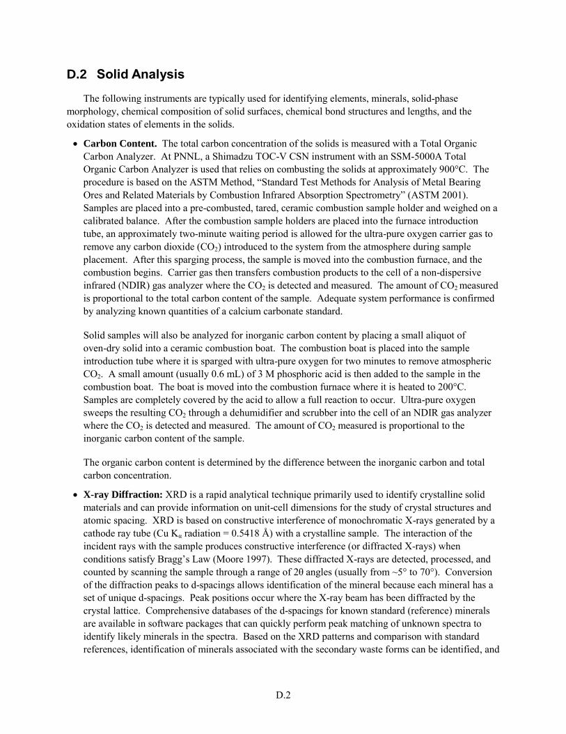
D.2
D.2 Solid Analysis
The following instruments are typically used for identifying elements, minerals, solid-phase morphology, chemical composition of solid surfaces, chemical bond structures and lengths, and the oxidation states of elements in the solids.
Carbon Content. The total carbon concentration of the solids is measured with a Total Organic Carbon Analyzer. At PNNL, a Shimadzu TOC-V CSN instrument with an SSM-5000A Total Organic Carbon Analyzer is used that relies on combusting the solids at approximately 900°C. The procedure is based on the ASTM Method, “Standard Test Methods for Analysis of Metal Bearing Ores and Related Materials by Combustion Infrared Absorption Spectrometry” (ASTM 2001). Samples are placed into a pre-combusted, tared, ceramic combustion sample holder and weighed on a calibrated balance. After the combustion sample holders are placed into the furnace introduction tube, an approximately two-minute waiting period is allowed for the ultra-pure oxygen carrier gas to remove any carbon dioxide (CO2) introduced to the system from the atmosphere during sample placement. After this sparging process, the sample is moved into the combustion furnace, and the combustion begins. Carrier gas then transfers combustion products to the cell of a non-dispersive infrared (NDIR) gas analyzer where the CO2 is detected and measured. The amount of CO2 measured is proportional to the total carbon content of the sample. Adequate system performance is confirmed by analyzing known quantities of a calcium carbonate standard.
Solid samples will also be analyzed for inorganic carbon content by placing a small aliquot of oven-dry solid into a ceramic combustion boat. The combustion boat is placed into the sample introduction tube where it is sparged with ultra-pure oxygen for two minutes to remove atmospheric CO2. A small amount (usually 0.6 mL) of 3 M phosphoric acid is then added to the sample in the combustion boat. The boat is moved into the combustion furnace where it is heated to 200°C. Samples are completely covered by the acid to allow a full reaction to occur. Ultra-pure oxygen sweeps the resulting CO2 through a dehumidifier and scrubber into the cell of an NDIR gas analyzer where the CO2 is detected and measured. The amount of CO2 measured is proportional to the inorganic carbon content of the sample.
The organic carbon content is determined by the difference between the inorganic carbon and total carbon concentration.
X-ray Diffraction: XRD is a rapid analytical technique primarily used to identify crystalline solid materials and can provide information on unit-cell dimensions for the study of crystal structures and atomic spacing. XRD is based on constructive interference of monochromatic X-rays generated by a cathode ray tube (Cu Kα radiation = 0.5418 Å) with a crystalline sample. The interaction of the incident rays with the sample produces constructive interference (or diffracted X-rays) when conditions satisfy Bragg’s Law (Moore 1997). These diffracted X-rays are detected, processed, and counted by scanning the sample through a range of 2θ angles (usually from ~5° to 70°). Conversion of the diffraction peaks to d-spacings allows identification of the mineral because each mineral has a set of unique d-spacings. Peak positions occur where the X-ray beam has been diffracted by the crystal lattice. Comprehensive databases of the d-spacings for known standard (reference) minerals are available in software packages that can quickly perform peak matching of unknown spectra to identify likely minerals in the spectra. Based on the XRD patterns and comparison with standard references, identification of minerals associated with the secondary waste forms can be identified, and
D.3
the average bulk composition of minerals is also determined semi-quantitatively based on the height of the identified peaks. In addition, the combination of a small angle X-ray scattering (SAXS) device with XRD can also reveal more information on the particle size distribution and pore size distribution of the samples.
X-ray Fluorescence: XRF is a nondestructive technique that is used to quantify the elemental composition of solid and liquid samples. XRF measures the emission of characteristic “secondary” (or fluorescent) X-rays from a sample that is being bombarded with high-energy X-rays or gamma rays. As photon energy (or an electron) is absorbed, a state of the target element changes from the ground state (lowest energy state) to an excited state (higher energy state). The excited state of the element then returns back to the normal ground state with the emission of a photon (fluorescence) or an electron in the outer shell of the orbital. Detection of the intensity and energy of emissions, which are characteristic of each element, is used for chemical elemental analysis. XRF is capable of detecting elements from aluminum to uranium in concentrations from ppm to 100 wt%. Through the use of appropriate reference standards, XRF can accurately quantify the elemental composition of both solid and liquid samples (Couture et al. 1993). XRF can analyze areas as small as 30 μm with a sampling depth as great at 10 μm. However, no elements lighter than Al can be measured by XRF without special thin window detectors. The XRF technique is generally part of an attachment to scanning electron microscopes (SEM) to allow chemical analysis of small regions of mounted solids. When combined with SEM, the common acronym is SEM-EDS (scanning electron microscopy–energy-dispersive spectroscopy).
Microscopes: Scanning electron microscopy rasters across a sample surface using a focused electron beam that provides high-resolution images of the sample surface. Transmission electron microscopy (TEM) and scanning transmission electron microscopy (STEM) are related techniques that use an electron beam to image a sample surface at even greater resolution (smaller sizes/areas probed). Using microscopes such as SEM, TEM, and STEM, the high-resolution images of surface morphology and particle size analysis in the solid waste form can be obtained. Analysis of surface morphology can be used for detecting cracks or any fractures that may develop in the waste forms. Compared to SEM, both TEM and STEM have better spatial resolution, even though they require significantly more sample preparation time and effort. However, in addition to outstanding image resolution, it is also possible to characterize crystallographic phase and crystallographic orientation by use of the diffraction mode in TEM.
SEM-EDS: Energy-dispersive X-ray spectroscopy (EDS or EDX) is an analytical technique used for the elemental analysis or chemical characterization of a sample. It is one of the variants of X-ray fluorescence spectroscopy that relies on the investigation of a sample through interactions between electromagnetic radiation and matter, analyzing X-rays emitted by the matter in response to being hit with charged particles. Its characterization capabilities are due in large part to the fundamental principle that each element has a unique atomic structure, allowing X-rays that are characteristic of an element's atomic structure to be identified uniquely from one another.
To stimulate the emission of characteristic X-rays from a specimen, a high-energy beam of charged particles such as electrons or protons, or a beam of X-rays, is focused into the sample being studied. At rest, an atom within the sample contains ground-state (or unexcited) electrons in discrete energy levels or electron shells bound to the nucleus. The incident beam may excite an electron in an inner shell, ejecting it from the shell while creating an electron hole where the electron was. An electron from an outer, higher-energy shell then fills the hole, and the difference in energy between the higher-
D.4
energy shell and the lower energy shell may be released in the form of an X-ray. The number and energy of the X-rays emitted from a specimen can be measured by an energy-dispersive spectrometer. The energy of the X-rays is characteristic of the difference in energy between the two shells and of the atomic structure of the element from which they were emitted, which allows the elemental composition of the specimen to be measured.
There are four primary components of the EDS setup: the beam source, the X-ray detector, the pulse processor, and the analyzer. A number of free-standing EDS systems exist. However, EDS systems are most commonly found on scanning electron microscopes (SEM-EDS) and electron microprobes. Scanning electron microscopes are equipped with a cathode and magnetic lenses to create and focus a beam of electrons, and since the 1960s they have been equipped with elemental analysis capabilities. A detector is used to convert X-ray energy into voltage signals; this information is sent to a pulse processor, which measures the signals and passes them on to an analyzer for data display and analysis.
Fourier Transform Infrared Spectroscopy (FTIR): FTIR provides specific information about chemical bonding and molecular structures, making it useful for analyzing organic materials and certain inorganic materials. Because chemical bonds vibrate at characteristic frequencies, a vibrational spectrum is also characteristic of a given sample, and individual vibration peaks are associated with the presence of particular structural groups within the sample, which can be used to infer the presence of particular phases or molecular groups. Vibrational spectra can be easily obtained for crystalline or amorphous solids, liquids, or gases and can be easily applied to systems involving elements of low atomic weight. Since a vibrational spectrum is dependent on the inter-atomic forces, temperature, and composition in a particular sample, it is a sensitive probe of the microscopic structure and bonding within the material. When the chemicals are exposed to infrared radiation, they absorb the radiation at frequencies that match their vibration modes. Measuring the radiation absorption as a function of frequency produces a spectrum that can be also used to identify functional groups and compounds.
Raman Spectroscopy (RS): RS also determines the chemical structure of a sample and identifies the compounds present by measuring molecular vibrations, similar to FTIR. However, the Raman method yields better spatial resolution and enables the analysis of smaller samples. Raman is a good technique for the qualitative analysis of organic and/or inorganic mixed materials and can also be employed for semi-quantitative and quantitative analysis. It can be used to identify inorganic compounds both in the bulk and in individual particles to 1) map the distribution of components in a sample through Raman imaging and depth profiling, 2) investigate the presence of different carbon types and their relative proportions, 3) determine inorganic oxides and their valence states, and 4) measure the stress and crystalline structure in weathered waste forms and other materials.
X-ray Photoelectron Spectroscopy (XPS): XPS is based on the photoelectric effect. When materials are bombarded with X-rays strong enough to eject electrons from the inner shell of atoms, the difference between the incoming photon energy and electron binding energy (B.E.) is converted to kinetic energy in the escaping photoelectron (Hochella 1988). A chemical shift, defined as the difference in B.E. between a particular line and the B.E. for the same line in a reference compound, can distinguish between two different oxidation states of an element in a given sample or between different coordination environments. Alternatively, XPS can be used to perform depth profiling of elemental composition to study alteration or dissolution of mineral (or waste form) surfaces. XPS is a surface-sensitive technique because it is based on detection of photoelectrons that have undergone no
D.5
inelastic collisions, and this can only happen near the surface. The depth of analysis is therefore typically between 10 and 50 Å. Because every element has a unique atomic structure, and the low-energy X-rays used can only excite a few atomic levels from each element, elements can be identified unambiguously in most cases. A wide-energy-range “survey” scan can be used to identify the elements present in the surface of a solid, but it is not used for quantification of elemental composition because it lacks resolution.
X-ray Absorption Spectroscopy: X-ray photon energy is used to eject a photoelectron from the core shell of an atom in the target material at the time of X-ray absorption. X-ray absorption occurs when an X-ray photon travels through solid matter. The intensity of the incident X-ray photon decreases by passing through the material, and the absorption coefficient is determined by the thickness of matter and the difference in intensities between incident and transmitted X-rays. As the energy of the photon increases, the absorption coefficient generally decreases until the incident energy reaches the threshold energy at which the absorption coefficient arises abruptly. The threshold energy is the minimum energy required to eject an electron from a core shell of an atomic orbital in the material. This sharp increment in the absorption coefficient is attributed to the photoelectron ejection and is referred to as the absorption edge. The absorption coefficient as a function of incident photon energy is used for the analysis of XAS. The photoelectron emitted by X-ray absorption is partially backscattered by the neighboring atoms before the ejection occurs (Teo 1986). Multiple scattering of ejected photoelectrons is used as the measuring technique in XANES, while a single scattering mainly occurs in extended X-ray absorption fine structure (EXAFS) measurement techniques. Both XANES and EXAFS spectroscopy probe only the local environment because of the low energy of photoelectrons. Both techniques are element selective and yield molecular local environmental information such as oxidation state, element identity, and bonding information (coordination numbers and bonding distance between the central and the nearest neighboring elements). The advantage of XAS is that most elements (except hydrogen) in the periodic table can be studied in all types of phases (crystalline, amorphous solids, liquids, gases, or mineral-water interfaces), even at low concentration levels (approximately 1 to 10 ppm). XAS is an in situ technique that does not need any special sample preparation like drying or vacuum conditions (Brown et al. 1988; Koningsberger and Prins 1988). The disadvantage of XAS techniques is that high-intensity X-ray sources (i.e., synchrotron radiation facility) are required, and the data collection and analysis processes are quite complicated/time consuming and expensive. Even though XAS is a short-range order probe (approximately 4 to 6 Å from the absorber) as compared to XRD, it provides remarkably unique information on the local structural environment in most materials so that it complements information from other spectroscopic methods to increase our understanding of binding and leaching mechanisms of contaminants from waste forms.
Gas Adsorption Analysis: Because the transport or diffusion processes of contaminants through porous materials are closely related to the specific surface area and the pore structure of the material, these physical characteristics need to be determined for waste forms/packages. The specific surface area is the amount of available surface area per unit weight of the solid material and can be measured at liquid nitrogen temperature (approximately 77 K) using the N2-BET method (Brunauer et al. 1938, Gregg and Sing 1982, Webb and Orr 1997). Pore information, including average pore diameter and pore volume (or area) distribution as a function of pore diameter, can be also obtained from the complete adsorption isotherm using the Barrett-Joyner-Halenda (BJH) method (Barrett et al. 1951).
D.6
Hg Porosimetry: The following web page has a good introduction: http://micromeritics3.reachlocal.com/coupon/?scid=1558580&cid=598524&tc=10090220270207283&rl_key=cea2debe12f833a3cb9abb5c05277bc9&kw=7605571&dynamic_proxy=1&primary_serv=micromeritics3.reachlocal.net&pub_cr_id=4701462369
Vertical Scanning Interferometry (VSI): VSI is an optical light technique in which minute changes in surface height can be detected (nanometer range), and the change in height can be correlated with a dissolution rate (Lüttge et al. 1999, Lasaga and Lüttge 2001, Lüttge and Conrad 2004, Green and Lüttge 2006, Koyunu et al. 2006). Before a dissolution test is run, a small portion of the test material is coated with a waterproof substance that protects the surface from reaction with water. During the test, the non-protected portion of the surface is subjected to dissolution, and the surface dissolves and retreats in height. After the test, the protective material is removed, and the protected area is used as a reference surface to which the height of the dissolved surface is compared. The difference in height is proportional to the dissolution rate. This technique is especially useful for quantifying dissolution rates of insoluble minerals, such as many glasses. In traditional dissolution tests, the test specimen is placed in a reactor filled with aqueous solution. Aliquots of solution are periodically collected, and the dissolution rate of the specimen is proportional to the concentration in the aliquot of dissolved elements released from the specimen. Because of the slow release of dissolved material to solution, concentrations of elements in solution that would normally quantify dissolution rates are very low, presenting analytical difficulties. However, by analyzing the change in height between the reference and reactive surface using the VSI technique, dissolution rates of sparingly soluble solids in solution can be easily quantified. Presently, the VSI technique is only available for use on nonradioactive samples.
X-ray MicroTomography (XMT): Different components of the solid lead to different X-ray absorption, such as denser elements showing stronger absorption. A visible-light image is generated by a fluorescent screen and then projected by an optical microscope onto a charge-coupled device (CCD) camera. The shadow projections of the object are recorded with a high-resolution CCD-based camera system. After correction and normalization of the projections, the tomograms can be reconstructed for 2-D and 3-D images using the filtered back-projection technique. Incoming X-ray energy of the synchrotron radiation is also controlled very precisely with the help of a double crystal monochromator set below and above the absorption edge of an element to be investigated. Only the distribution of the particular element becomes visible using this setup because the absorption of all other elements stays practically constant across the absorption edge (Tricart et al. 2000). The synchrotron-based XMT apparatus achieves spatial resolutions of 3 to 5 μm and can determine attenuation coefficients to about 5% accuracy for single voxels while the conventional tomography technique has 10- to 200-μm spatial resolution, depending on the size of the specimen and X-ray source. Because the brightness differences in the reconstructed tomograph slice are normally a replica of the material’s density distribution, chemical compositions can be distinguishable by creating image contrasts, which then allow specific elements to be distinguished. Use of this behavior also allows development of 3-D elemental distribution maps of the sample. Three-D images of the internal microstructure of mixed solids and pore structure characteristics of the Cast Stone are the key uses planned for XMT.
Nuclear magnetic resonance (NMR) spectroscopy: NMR spectroscopy is a technique to study the static structure and dynamic behavior of condensed phases because it directly examines the properties of specific elements located in solid matrices and often offers significant advantages over diffraction methods and vibrational spectroscopy (Kirkpatrick 1988). The nuclei of many elemental isotopes
D.7
have characteristic spins, such as integral spin, fractional spin, and zero spin. In the presence of an external magnetic field, two spin states exist in nuclei, +1/2 and −1/2, and the magnetic field causes the spin system to tip with respect to the applied magnetic field. Irradiation of a sample with radio frequency energy corresponding exactly to the spin state separation of a specific set of nuclei will cause excitation of those nuclei in the +1/2 state to the higher −1/2 spin state. An NMR spectrum can be acquired by varying or sweeping the magnetic field over a small range while observing the radio frequency signal from the sample (Stebbins 1988). Coordination information of species, bonding arrangements, and the diffusion coefficient of hydrogen can be determined using the NMR spectra, including chemical shift, chemical exchange, and nuclear spin relaxation in the waste forms.
Mössbauer Spectroscopy: Mössbauer spectroscopy involves the resonant emission and absorption of gamma radiation by specific atomic nuclei in solids (Hawthorne 1988). Mössbauer spectroscopy is similar to the NMR spectroscopy. In Mössbauer spectroscopy, a solid sample is exposed to a beam of gamma radiation, and a detector measures the intensity of the beam transmitted through the sample. The atoms in the source emitting the gamma rays must be of the same isotope as the atoms in the sample absorbing them. A significant fraction of the emitted gamma rays will not lose energy to recoil and thus will have approximately the right energy to be absorbed by the target atoms. In the resulting spectra, gamma-ray intensity is plotted as a function of the source velocity. At velocities corresponding to the resonant energy levels of the sample, some of the gamma rays are absorbed, resulting in a drop in the measured intensity and a corresponding dip in the spectrum. The number, positions, and intensities of the peaks provide information about the chemical environment of the absorbing nuclei and can be used to characterize solids. Because of extremely fine energy resolution, Mössbauer spectroscopy can detect even subtle changes in the nuclear environment of the relevant atoms, identify the presence of particular compounds and phase transformations (e.g., the ratio of Fe2+ to Fe3+), and provide the crystallite size and grain structure of a material.
Reduction Capacity Procedures: See Angus and Glasser (1985) and Lee and Batchelor (2003).
D.3 References
Angus MJ and FP Glasser. 1985. “The Chemical Environment in Cement Matrices.” Mat. Res. Soc.
Symp. Proc. 50:547–556.
ASTM—American Society for Testing and Materials. 2001. Standard Test Methods for Analysis of
Metal Bearing Ores and Related Materials by Combustion Infrared Absorption Spectrometry. E1915-01, West Conshohocken, Pennsylvania.
Barrett EP, LG Joyner, and PP Halenda. 1951. “The Determination of Pore Volume and Area Distributions in Porous Substances. I. Computations from Nitrogen Isotherms.” J. Am. Chem. Soc. 73:373–380.
Brown GE, G Calas, GA Waychunas, and J Petiau. 1988. “X-ray Absorption Spectroscopy and Its Applications in Mineralogy and Geochemistry.” In Spectroscopic Methods in Mineralogy and Geology, ed. FC Hawthorne. Mineralogy Society of America, Washington D. C.
Brunauer S, PH Emmett, and E Teller. 1938. “Adsorption of Gases in Multimolecular Layers.” Journal
of the American Chemical Society 60:309–319.
D.8
Couture RA, MS Smith, and RF Dymek. 1993. “X-ray fluorescence analysis of silicate rocks using fused glass discs and a side-window Rh source tube: accuracy, precision and reproducibility.” Chemical
Geology 110:315–328.
Gregg SJ and KSW Sing. 1982. Adsorption, Surface Area, and Porosity. 2nd ed. Academic Press, Inc., Orlando, Florida.
Green E, and A Lüttge. 2006. “Incongruent Dissolution of Wollastonite Measured with Vertical Scanning Interferometry.” American Mineralogist 91:430-434.
Hawthorne FC. 1988. “Mossbauer spectroscopy.” In Spectroscopic Methods in Mineralogy and
Geology, ed. FC Hawthorne. Reviews in Mineralogy 18:573–637.
Hochella MF, Jr. 1988. “Auger electron and X-ray photoelectron spectroscopies.” In: Spectroscopic
Methods in Mineralogy and Geology, ed. FC Hawthorne). Reviews in Mineralogy 18:573-637.
Kirkpatrick RJ. 1988. “MAS NMR spectroscopy of minerals and glasses.” In: Mineral-water Interface
Geochemistry, ed. FC Hawthorne. Mineralogical Society of America 18:431–512.
Koningsberger DC and R Prins. 1988. X-ray Absorption: Principles, Applications, Techniques of
EXAFS, SEXAFS, and XANES. Wiley, New York.
Koyuncu I, J Brant, A Lüttge, and MR Riesner. 2006. “A Comparison of Vertical Scanning Interferometry (VSI) and Atomic Force Microscopy (AFM) for Characterizing Membrane Surface Topography.” Journal of Membrane Science 278: 410-417.
Lasaga AC and A Lüttge. 2001. “Variation of Crystal Dissolution Rate Based on a Dissolution Stepwave Model.” Science 291(5512):2400–2404.
Lee W and B Batchelor. 2003. “Reductive Capacity of Natural Reductants.” Environmental Science
Technology 37:535-541.
Lüttge A, EW Bolton, and AC Lasaga. 1999. “An Interferometric Study of the Dissolution Kinetics of Anorthite: The Role of Reactive Surface Area.” American J. of Science 299: 652-678.
Lüttge A and PG Conrad. 2004. “Direct Observation of Microbial Inhibition of Calcite Dissolution.” Applied and Environmental Microbiology 70:1627-1632.
Moore DM and RC Reynolds, Jr. 1997. X-Ray diffraction and the Identification and Analysis of Clay
Minerals. 2nd ed. Oxford University Press, New York.
Stebbins JF. 1988. “NMR spectroscopy and dynamic process in mineralogy and geochemistry.” In Mineral-water Interface Geochemistry, ed. FC Hawthorne. Mineralogical Society of America 18:431–512.
Teo BK. 1986. “EXAFS: Basic Principles and Data Analysis.” Inorganic Chemistry Concepts. Springer-Verlag, New York.
Tricart JP, M Van Geet, and A Sasov. 2000. “Using Micro-CT for 3D characterization of geological materials.” Microscopy and Analysis 65:31.

D.9
Webb PA and C Orr. 1997. Analytical Methods in Fine Particle Technology. Micromeritics Instrument Corporation, Norcross, Georgia.


