sdi encoder + logger...the sdi-12 encoder+logger instruction manual and encoderset gui interface is...
TRANSCRIPT

www.stevenswater.com 1-1
SDI ENCODER + LOGGER
Operations Manual

www.stevenswater.com 1-2
Contents
1 SAFETY AND EQUIPMENT PROTECTION INFORMATION ....................................................1-3
2 SDI-12 ENCODER+LOGGER EQUIPMENT AND PARTS ............................................................2-5
2.1 SYSTEM REQUIREMENTS ......................................................................................................................2-5 2.2 USEFUL TOOLS AND PERIPHERALS.......................................................................................................2-5 2.3 GENERAL DESCRIPTION .......................................................................................................................2-5
3 BASIC PRINCIPLES OF OPERATION .............................................................................................3-6
3.1 POWER / GROUND TERMINALS .............................................................................................................3-6 3.2 USB CONNECTION ...............................................................................................................................3-7 3.3 SD CARD SOCKET ................................................................................................................................3-7 3.4 MEMORY..............................................................................................................................................3-7 3.5 VOLATILE MEMORY .............................................................................................................................3-7 3.6 NON-VOLATILE MEMORY .....................................................................................................................3-7
4 TECHNICAL SPECIFICATION .........................................................................................................4-1
5 INSTALLATION ...................................................................................................................................5-2
MECHANICAL INSTALLATION ...................................................................................................................5-2 5.1 .................................................................................................................................................................5-2 5.2 ELECTRICAL INSTALLATION ................................................................................................................5-3
5.2.1 Connecting Power .....................................................................................................................5-3 5.2.2 Grounding and Protection from Lightning ................................................................................5-3
5.3 FRONT PANEL OPERATION ...................................................................................................................5-4 5.4 LCD DISPLAY BACKUP BATTERY INSTALLATION ................................................................................5-5
6 SDI-12 ENCODER+LOGGER SET UP & CONFIGURATION ......................................................6-1
6.1 INSTALL ENCODERSET .........................................................................................................................6-1 6.2 ENCODERSET MAIN MENU ..................................................................................................................6-2
6.2.1 .........................................................................................................................................................6-2 #1 Com Port, #2 Connect and #3 Disconnect Connection .......................................................................6-2 6.2.2 Logger Configuration ................................................................................................................6-4 Shaft Encoder Channel .......................................................................................................................6-5
6.3 DATA MANAGEMENT 2.0 ...................................................................................................................6-16 6.3.1 RAW SD CARD DATA .............................................................................................................6-17
7 MAINTENANCE AND TROUBLE SHOOTING ............................................................................7-18
7.1 MAINTENANCE .............................................................................................................................7-18 7.1.1 Battery .....................................................................................................................................7-18 7.1.2 Moisture ...................................................................................................................................7-18 7.1.3 Cleaning ..................................................................................................................................7-18
7.2 TROUBLE SHOOTING ...................................................................................................................7-18 7.2.1 Common Troubleshooting Issues .............................................................................................7-19
7.3 MAC ADDRESSES AND ETHERNET CONNECTION ...............................................................................7-20 7.4 GROUNDING AND PROTECTION FROM LIGHTNING..............................................................................7-20
www.stevenswater.com 1-3
1 Safety and Equipment Protection Information Before performing any procedures in this manual, please read all applicable WARNINGS and CAUTIONS in this section. Power sources, including batteries, can be a particular hazard to the user. The SDI-12 ENCODER+LOGGER instruction manual and EncoderSet GUI interface is organized so that the experienced user can operate the instrument with the least amount of reading. WARNING! ELECTRICAL POWER CAN RESULT IN DEATH, PERSONAL INJURY OR CAN CAUSE DAMAGE TO EQUIPMENT. If the instrument is driven by an external power source, disconnect the instrument from that power source before attempting any repairs. WARNING! BATTERIES ARE DANGEROUS. IF HANDLED IMPROPERLY, THEY CAN RESULT IN DEATH, PERSONAL INJURY OR CAN CAUSE DAMAGE TO EQUIPMENT. Batteries can be hazardous when misused, mishandled, or disposed of improperly. Batteries contain potential energy, even when partially discharged. WARNING! ELECTRICAL SHOCK CAN RESULT IN DEATH OR PERSONAL INJURY. Use extreme caution when handling cables, connectors, or terminals; they may yield hazardous currents if inadvertently brought into contact with conductive materials, including water and the human body. CAUTION! Be aware of protective measures against environmentally caused electric current surges. In addition to the previous warnings and cautions, the following safety activities should be carefully observed. Children, Adolescents NEVER give batteries to young people who may not be aware of the hazards associated with batteries and their improper use or disposal. Jewelry, Watches, Metal Tags To avoid severe burns, NEVER wear rings, necklaces, metal watch bands, bracelets, or metal identification tags near exposed battery terminals. Heat, Fire

www.stevenswater.com 1-4
NEVER dispose of batteries in fire or locate them in excessively heated spaces. Observe the temperature limit listed in the instrument specifications. Charging NEVER charge “dry” cells or lithium batteries that are not designed to be charged. NEVER charge rechargeable batteries at currents higher than recommended ratings. NEVER recharge a frozen battery. Thaw it completely at room temperature before connecting charger. Unvented Container NEVER store or charge batteries in a gas-tight container. Doing so may lead to pressure buildup and explosive concentrations of hydrogen. Short circuits NEVER short circuit batteries. High current flow may cause internal battery heating and/or explosion. Damaged Batteries Personal injury may result from contact with hazardous materials from a damaged or open battery. NEVER attempt to open a battery enclosure. Wear appropriate protective clothing and handle damaged batteries carefully. Disposal ALWAYS dispose of batteries in a responsible manner. Observe all applicable federal, state, and local regulations for disposal of the specific type of battery involved. NOTICE Stevens makes no claims as to the immunity of its equipment against lightning strikes, either direct or nearby. The following statement is required by the Federal Communications Commission: WARNING - This equipment generates, uses, and can radiate radio frequency energy with the optional Wi-Fi module and, if not installed in accordance with the instructions manual, may cause interference to radio communications. It has been tested and found to comply with the limits for a Class A computing device pursuant to Subpart J of Part 15 of FCC Rules, which are designed to provide reasonable protection against such interference when operated in a commercial environment. USER INFORMATION Stevens makes no warranty as to the information furnished in these instructions and the reader assumes all risk in the use thereof. No liability is assumed for damages resulting from the use of these instructions. We reserve the right to make changes to products and/or publications without prior notice.

www.stevenswater.com 2-5
2 SDI-12 ENCODER+LOGGER Equipment and Parts Thank you for purchasing a SDI-12 ENCODER+LOGGER from Stevens Water Monitoring Systems Inc. (Stevens). Please unpack and examine the SDI-12 ENCODER+LOGGER parts carefully. If there is any apparent shipping damage, contact the shipper immediately. Also, contact the Stevens for replacement of the unit. In this package you will find the following parts: 1. SDI-12 ENCODER+LOGGER unit in a Nema4 enclosure with bearing housing and mounting
stand. 2. One power cable 3. USB A to B cable 4. Two Fast-on® terminal connectors and two spade lugs for battery power connection 5. A CD containing
a. Stevens’ EncoderSet Windows logger configuration software b. Data Management MS Excel macro program for data download in column format c. SDI-12 ENCODER+LOGGER manual d. SDI-12 ENCODER+LOGGER data sheet
6. One removable SD memory card (2 gigabyte)
2.1 System Requirements External power: either a 12V battery with at least 3 amp hours or a standard AC to DC power source. 1. USB cable or Stevens’ Shark™ Bluetooth RS232/RS485 adapter (a “wireless serial cable”) for
programming / configuration using a PDA or computer 2. A PC, or laptop computer equipped with:
a. USB-to-serial port adapter, or USB port b. Stevens’ EncoderSet loaded on laptop computer.
2.2 Useful Tools and Peripherals Small standard 3.0 x 100mm screwdriver for power connections
2.3 General Description The SDI-12 ENCODER+LOGGER is a programmable data logger / encoder instrument in a compact, rugged NEMA4 fiberglass enclosure, designed using the latest Digital Signal Processing (DSP) technology. The USB port is provided for communication, setup, and downloading of stored data. Programming / configuration data transfer rates is set at 38.4K BAUD. Reporting data transfer for telemetry purposes is user programmable between 1200 to 115,200 BAUD. Data format is 8 data bits, 1 stop bit, and no parity. The SDI-12 ENCODER+LOGGER provides for programmable flow measurements with standard flumes or weirs.

www.stevenswater.com 3-6
3 Basic Principles of Operation The SDI-12 ENCODER+LOGGER is designed for long-term, low power operation. At a specified time, usually corresponding to initiation of a recording interval or a report mode, the logger will wake up to perform the necessary operations, and then return to the sleep mode. Recording of sensor readings is on a time interval basis. Primary applications for the SDI-12 ENCODER+LOGGER are float operated datalogging system and those combining the unit with some form of telemetry. The unit can be optimized for the particular transmission method employed. The SDI-12 ENCODER+LOGGER can be programmed with various telemetry communication protocols including:
GOES or similar geostationary satellite data collection platform (DCP) applications.
Terrestrial applications include standard phone, cell phone, and line-of-sight radio links. Line-of-sight radio can either be one-way, with self-initiated transmissions, or two-way, with polled data access.
When a terminal or computer is attached to USB 1 the unit enters the Operational Mode automatically, once the user opens EncoderSet, selects the proper Com Port, and clicks “connect”. This allows full access to all setup commands needed to configure the logger and manually downloading data. The user can configure the SDI-12 ENCODER+LOGGER using EncoderSet. If the SDI-12 ENCODER+LOGGER is scheduled for a logging interval while connected using EncoderSet, the Logging interval will take priority and then EncoderSet will resume operations.
3.1 Power / Ground Terminals The power and ground terminals are used to supply 12Vdc power to the SDI-12 ENCODER+LOGGER. The SDI-12 ENCODER+LOGGER can operate between 9.6 – 16Vdc with a minimum current of 3mA and maximum current of 2200mA. However, when the primary power drops below 9.6Vdc for 10 seconds, the SDI-12 ENCODER+LOGGER will shut down by stopping the execution of logging procedures. Logged data will be automatically be transferred to the external SD card just prior to logger - shutting down as a result of low voltage input. The SDI-12 ENCODER+LOGGER will automatically restart when the power supply exceeds 9.6Vdc. Low power will be logged to the SDI-12 ENCODER+LOGGER internal Log (see section 1.10 on operational diagnosis & log)
In event of low power automatic shut down the SDI-12 ENCODER+LOGGER’s programming and stored data remain in flash memory, and the clock continues to keep time when power is disconnected. The clock is powered by an internal lithium battery. If the 3 V internal lithium battery drops below 1.1V, or is removed, the clock will no longer keep the correct time.
The SDI-12 ENCODER+LOGGER is diode protected against accidental reversal of positive and ground leads from the battery.

www.stevenswater.com 3-7
3.2 USB Connection The USB data transfer is compatible with both USB 1.0 and USB 2.0 protocols. The USB port is not a USB controller or hub. It is a downstream protocol. USB B connector standards indicated downstream protocol.
3.3 SD Card Socket The SDI-12 ENCODER+LOGGER utilizes a push to eject SD card socket. The user can simply push a SD memory card into the socket and push again to eject. The SDI-12 ENCODER+LOGGER is provided with an internal industrial grade SD Card – using the FAT or FAT16 format. The external SD card provided is a commercial grade rated at 0 to 70˚ C. An optional industrial grade external SD card can be provided for lower temperature ranges.
3.4 Memory The SDI-12 ENCODER+LOGGER contains both volatile and non-volatile memory subsystems.
3.5 Volatile memory For storage of information needed quickly, such as scratch pads used in calculations, the SDI-12 ENCODER+LOGGER has static RAM internal in each of its microprocessor chips.
3.6 Non-volatile memory The SDI-12 ENCODER+LOGGER programming and configuration file programmed using EncoderSet are store in the microprocessor chip’s flash memory.
In addition to the externally accessible 2 Gigabyte SD card, the SDI-12 ENCODER+LOGGER has an internal, permanently secured SD card that stores up to 2 Gigabytes of logged data.
This internal SD card contains all the logged data until it is erased. If the data file exceeds 2,000 megabytes, the SDI-12 ENCODER+LOGGER will overwrite the oldest data.
The SDI-12 ENCODER+LOGGER automatically transfers data it has collected since the top of the hour from the internal SD card to the external SD card. This data is stored in the file xxxxxxxB.csv on the external SD card. B is appending to the last time transfer. The xxxxxxx is the month and year , and the last four characters of the SDI-12 ENCODER+LOGGER’s MAC address. The file xxxxxxxA.csv is created when the data is manually transferred from the internal SD to external SD card using EncoderSet. If there is no external SD Card, or the SD Card is not clicked into place, the SDI-12 ENCODER+LOGGER will recognize the external SD Card is missing and will not attempt to write data to this external memory port.

www.stevenswater.com 4-1
4 Technical Specification SDI-12 ENCODER+LOGGER
Power Requirements
9.6 - 16 Vdc, 4 mA standby current (telemetry system may require additional power)
Processor
32-bit ARM (Ethernet), 16 bit TI MSP430 and two 16-bit dsPIC33 microprocessors from Microchip Inc.
On-Board Data Storage
FLASH storage, 2 Gigabytes internal plus removable 2 Gigabyte SD memory card
Recording (sampling) Interval
1 minute to 24 hours
Real-Time Clock
Accurate +/- 1 minute/month, leap year correction, temperature correction. Lithium battery backup
Non-Volatile Memory
All setup parameters – FLASH within the microprocessor
Message Size
Virtually no maximum
USB Port
USB 2.0 backwards compatible with USB 1.0
Communications
USB 2.0 (fully compatible with USB 1.0 devices)
Removable SD card
Watchdog Timer
System resets and “rights” itself after a microprocessor failure
Temperature and Humidity
Operating: -40 to 158 F (-40 to 70 C)
NEMA 4 enclosure: 100% condensing
Aluminum enclosure: 95% non-condensing
Sensor Input (Integrated)
Serial:
Input type: SDI-12
Sensor power: 12 VDC continuous, 12 VDC under firmware control (switched)
Physical Size (L x H x D) for outside dimensions of NEMA-4 enclosure with lid.
8.25 inch (includes the base) x 7.50 inch x 8.75 inch (includes shaft extension)
(20.96 cm x 19.05 cm x 22.23 cm)
www.stevenswater.com 5-2
5 Installation
5.1 Mechanical Installation Unpack and examine the SDI-12 ENCODER+LOGGER carefully. If there is any apparent shipping damage, contact the shipper immediately. Also contact the factory for replacement of the unit.
Position the SDI-12 ENCODER+LOGGER so it can be connected to a suitbable power source. Make sure that the external enclosure you have selected provides enough side room to accommodate any external cable connections.
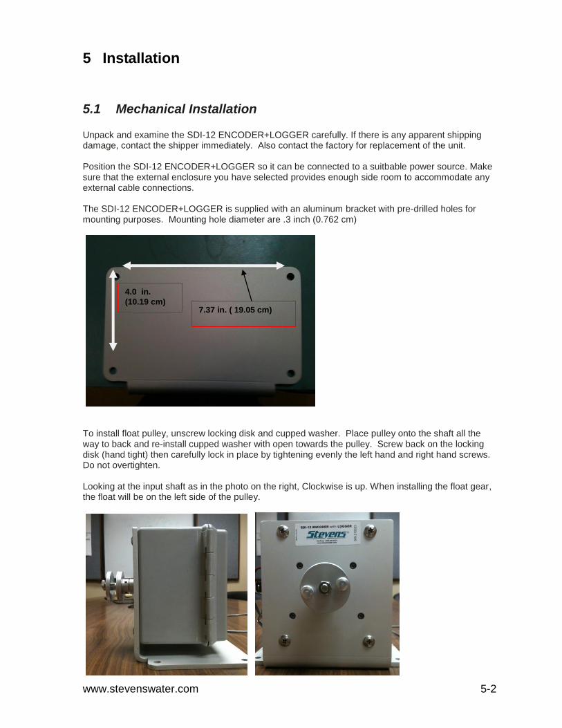
The SDI-12 ENCODER+LOGGER is supplied with an aluminum bracket with pre-drilled holes for mounting purposes. Mounting hole diameter are .3 inch (0.762 cm)
To install float pulley, unscrew locking disk and cupped washer. Place pulley onto the shaft all the way to back and re-install cupped washer with open towards the pulley. Screw back on the locking disk (hand tight) then carefully lock in place by tightening evenly the left hand and right hand screws. Do not overtighten. Looking at the input shaft as in the photo on the right, Clockwise is up. When installing the float gear, the float will be on the left side of the pulley.
7.37 in. ( 19.05 cm)
4.0 in.
(10.19 cm)

www.stevenswater.com 5-3
5.2 Electrical Installation
5.2.1 Connecting Power Connect the 12Vdc power cable to the SDI-12 ENCODER+LOGGER. (See section 1.8 on more information on Power supply). Barrier strip located on the side of the SDI-12 ENCODER+LOGGER provides the connections to Power and Ground. Plus (+) sign for Power and a negative Sign (-) for ground. Input power requirements: 12 VDC.
5.2.2 Grounding and Protection from Lightning Every remote environmental monitoring station should include a plan for an Earth Ground. For more information on this important topic when setting up your SDI-12 ENCODER+LOGGER, please see Ground and Protection section for additional reference information.

www.stevenswater.com 5-4
5.3 Front Panel Operation
Front panel consist of a display with an “UP” button, a “DOWN” button and LCD “ON” button, LED
Green light, SD Card Slot , USB host connection.
Pressing the “UP” button will increment the reading. Keeping the button depressed it will increment at
an increasing rate.
Pressing the “DOWN” button will decrement the reading. Keeping the button depressed will
decrement the reading at an increasing rate.
LED Green light. Solid green light indicates logger is busy either taking a reading or is connected to a
computer. Blinking light indicates the unit is active.
SD Card slot: accommodates a 2 GB SD card.
UP BUTTON
DOWN BUTTON
“LCD “ON” BUTTON BUTTON
USB CONNECTION
SD CARD SLOT
LED GREEN LIGHT

www.stevenswater.com 5-5
5.4 LCD Display Backup battery installation
The LCD display is supplied with a 9 VDC battery that is not installed. To install disconnect any
external power and remove the 4 mounting screws that hold the front panel in place. Open slowly so
as to not disturb any of the internal wiring connections.
Insert the battery and re-install the front panel taking care to make sure that no cables are pinched in
the process.
To test, disengage any external power and then press the LCD “ON” button. The display should turn
on showing zeros. If not, then check the 9 Volt Battery connection again to make sure it properly
installed.

www.stevenswater.com 6-1
6 SDI-12 Encoder+LOGGER Set Up & Configuration
6.1 Install EncoderSet Install EncoderSet from the CD that accompanied your SDI-12 ENCODER+LOGGER unit, or download it from Stevens’ website at http://www.stevenswater.com/software/downloads.aspx. If the software screen does not start automatically, go to “My Computer,” click on the CD drive, and click on the setup.exe file under the EncoderSet Desktop folder. EncoderSet works on computers with Windows 2000, XP, or Vista, or Windows 7 operating systems. Insert the CD into your computer and click on setup.exe. The program will automatically check to see if your computer has .NET Framework 3.5, and if not, it will be installed automatically. This download of .NET Framework 3.5 is approximatly15MB and may take some time to install on your computer. (Note: you do not need to be concerned whether your computer has MS Visual Studio or not). If your computer already has .NET Framework 3.5, or after loading this file, the EncoderSet and Data Management program will automatically install on your computer. By default this will be placed under your computer’s program files under Stevens then under EncoderSet. EncoderSet and Data Management will also appear as desktop icon. Data Management is a Microsoft Excel macro application. You can use this application to convert the stored raw data to readable table format. You are now ready to connect to a SDI-12 ENCODER+LOGGER. First connect a power supply to the SDI-12 ENCODER+LOGGER. When you connect to any SDI-12 ENCODER+LOGGER for the first time via a USB connection, the computer will ask for the USB hardware driver. This is located on the CD under USB Driver folder. Click on the file under the USB Driver folder called “CDM 2.04.06.exe.” You only have to load the driver once and it is best to load it before a SDI-12 ENCODER+LOGGER is connected to the computer via a USB port connection. If you connect via the RS232 serial port, no driver is required.

www.stevenswater.com 6-2
6.2 EncoderSet Main Menu
6.2.1
#1 Com Port, #2 Connect and #3 Disconnect Connection
The connection default between the SDI-12 ENCODER+LOGGER and PC is 38,400 baud and cannot be changed. This should not need any adjusting on your PC for USB connection. If you connect via a USB cable, EncoderSet will automatically detect the com port and show USB Serial Port (COM#). The USB Serial Port Number changes when you connect another SDI-12 ENCODER+LOGGER, so it is best to click on “refresh Com Port List” for EncoderSet to automatically detect the correct USB com port being used by your PC. Once the Com Port is established, click on the “Connect” button in the upper right hand side of the main menu (see Figure 3.1). A prompt will appear stating in a pop up screen “Do you want to download configuration for the logger ?, Yes or No. If you click yes, EncoderSet will download the SDI-12 ENCODER+LOGGER configuration setup into EncoderSet. You will see a time clock for a short period (less than 10
#1 #2
#3

www.stevenswater.com 6-3
seconds) while the configuration file is being copied from the SDI-12 ENCODER+LOGGER to the EncoderSet. If you click No, EncoderSet will have no configuration settings.
Figure 3.1 EncoderSet main screen Troubleshooting: If EncoderSet says “Logger cannot be connected”
Power to the SDI-12 ENCODER+LOGGER may not be on
Cable may not be firmly connect to the SDI-12 ENCODER+LOGGER or PC
Logger is busy transferring internal memory to external SD card.
Contact Stevens if you still have “SDI-12 ENCODER+LOGGER cannot be connected” problem.
Disconnection Procedures. It is important to either click disconnect or close EncoderSet, which will automatically disconnect EncoderSet from the SDI-12 ENCODER+LOGGER, and then remove the USB from the SDI-12 ENCODER+LOGGER. If the USB cable is removed before EncoderSet is disconnected, the SDI-12 ENCODER+LOGGER remains in EncoderSet mode and the USB and Comm 1 ports still assume a connection. If this is done, reconnect using the same cable that was removed prior to disconnecting EncoderSet. Then disconnect EncoderSet. Then remove the cables. NOTE: improper disconnect will not impact the logging and report of sensor data.

www.stevenswater.com 6-4
6.2.2 Logger Configuration On the main Menu screen, click on “Logger information tab “Logger Configuration” screen will appear.
a. Logger Name: Name given to the associated logger. Maximum b. Update Logger Name: Click to update logger name. c. MAC Address: This is automatically assigned by the SDI-12 ENCODER+LOGGER firmware
to be the last seven characters of the SDI-12 ENCODER+LOGGER’s globally unique MAC Address.
d. Firmware version: Firmware version that is running on the SDI-12 ENCODER+LOGGER e. New Password: User can select a password for access use. f. Update Password: Click to update the password. g. No Password: If no password is needed, check mark box to disable password. h. Computer Date: PC’s computer date.
#4
A B
F
G
H
I
E
D
J
K
L
C

www.stevenswater.com 6-5
i. Computer Time: EncoderSet reads and reports your PC’s configured date and time. j. Logger Date: SDI-12 ENCODER+LOGGER internal date. k. Logger time: EncoderSet automatically reads the SDI-12 ENCODER+LOGGER internal
date and time per the SDI-12 ENCODER+LOGGER’s internal clock when EncoderSet is connected to the SDI-12 ENCODER+LOGGER. The incremental time displayed is this field after the SDI-12 ENCODER+LOGGER time is received is based on the PC clock.
l. Update Logger Time: If you want to change the SDI-12 ENCODER+LOGGER date and/or time to the New SDI-12 ENCODER+LOGGER date and/or time, click on “Update SDI-12 ENCODER+LOGGER Time”. This updated date and/or time will appear in the SDI-12 ENCODER+LOGGER time and will automatically be saved by the SDI-12 ENCODER+LOGGER even if you don’t upload a new configuration file.
NOTE: It is recommend not to click on “Upload to Logger” until you have finished filling out all configuration screens. When you have finished the entire configuration that is required for your application, click on the “Upload to Logger” button to upload your configuration to logger. A copy of the current configuration will be automatically saved on your PC under C:\Program Files\Stevens\EncoderSet\Configuration\xxxxxxx-upload.lcf. xxxxxxx represents the last seven(7) characters of the SDI-12 ENCODER+LOGGER’s MAC address
6.2.2.1 Shaft Encoder Channel
a
b
c
d
e
f
g
h
i
j
#5
k

www.stevenswater.com 6-6
a. Battery Channel: User defined name that the battery voltage will be logged and identified by
– up to eight (8) characters b. Logging Interval: frequency of logging the battery voltage. If no logging is required, indicate
“Disabled” in this field.. c. Reporting Interval: frequency of reporting logged values if telemetry device is connected and
programmed with the SDI-12 ENCODER+LOGGER. If no telemetry device, indicate “Disabled” in this field.
d. Decimal Place: The logged value can be logged / reported up to four (4) decimal places e. Shaft Encoder Channel: User defined name that the encoder channel will be logged and
identified – up to eight (8) characters. f. Logging Time Offset: Logging interval is from the top of the hour. This feature will shift the
logging time. g. Logging Interval: Frequency of logging the encoder SDI-12. If no logging is required,
indicate “Disabled” in this field. h. Scale: a multiplier value of raw readings. Default is 1 ( Raw value X Scale ) + Offset i. Offset: offset of raw readings. Default is 0 ( Raw value X Scale ) + Offset j. Decimal place: The logged value can be logged / reported up to four (4) decimal places. k. Current readings. Will

www.stevenswater.com 6-7
6.2.2.2 Flow channel
a. Enable Flow Channel: b. Flow Unit: There are four different flow units. (Cubic feet per second, Gallons per second,
Gallons per minute, and Million gallons per day) c. Primary Device: Six different standard shapes of the flume or weir are selectable:
V-notch weir
Rectangular weir with end contractions
Rectangular weir without end contractions
Cipolletti (Trapezoidal) weir
Parshall flume
Palmer-Bowlus flume) d. Sampling Interval: frequency of sampling the selected channel to update the master
totalizer. e. Degree: Only if you select V-notch weir as the primary device. Otherwise, it will ask for the
crest length. f. Current Flow Value: Current flow measurement reading. g. Master Totalization (Gallons): Master totalization reading. h. Refresh Totalizer and Flow: Ask for the current flow measurement reading.
a
b
i
h
g
f
e
d
c

www.stevenswater.com 6-8
i. Reset Master Totalization: Reset Master totalization reading back to 0. Password is required (Call Stevens to obtain the password)

www.stevenswater.com 6-9
6.2.2.3 Telemetry
a. Serial Baud Rate: Adjust the serial port baud rate from 1200 to 115200. (Check the documentation for your telemetry devices to determine what baud rate to SDI-12 ENCODER+LOGGER use.
b. Transmit Header: Logger can transmit channel name, channel number, or both channel name and channel number along with the reporting data.
a
b

www.stevenswater.com 6-10
6.2.2.4 SDI-12 Transparent Mode
a. Command field: command that will send to the SDI-12 sensor (an exclamation mark (!) is required at the end of the command).
b. Send Command: send command to the SDI-12 sensor c. Clear result: clear the screen d. Screen information: return SDI-12 sensor’s response
a c b
d

www.stevenswater.com 6-11
SDI-12 COMMANDS:
The D and T commands return the setting in the response. After the C command, use the G command to get the setting.
aXI! - initialize the encoder to zero. aXC [float]! pulley circumference factor. aXD [int]! LCD timeout after button is pushed. Set to zero for always on. aXT [int]! internal sample rate in seconds. aXG! return value from last command.
SDI-12 command: 1XC! Response from sensor 1XOK
SDI-12 command: 1XG! Response from sensor 1X +1.0000
SDI-12 command: 1XD! Response from sensor 1XLCD 30
SDI-12 command: 1XT! Response from sensor 1XT 1
www.stevenswater.com 6-12
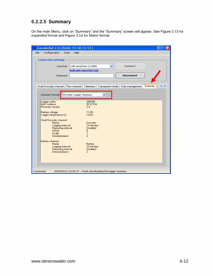
6.2.2.5 Summary On the main Menu, click on “Summary” and the “Summary” screen will appear. See Figure 3.13 for expanded format and Figure 3.14 for Matrix format.

www.stevenswater.com 6-13
ENCODER+LOGGER Summary: Channel settings summary. EncoderSet Summary Channel settings from EncoderSet which resides on the computer Immediately after you upload or download, the SDI-12 ENCODER+LOGGER summary and EncoderSet Summary will be the same.

www.stevenswater.com 6-14
6.2.2.6 Data Management .
a. Copy data to external SD Card: Manual command to copy the data from internal memory to the external SD card. Note: the SDI-12 ENCODER+LOGGER automatically transfers logged data from internal member to SD card once per hour.
b. Delete internal data: Clears the internal data file. Historical logged data will be deleted. c. Format internal memory: Format internal memory. Everything will be deleted. If this feature
is clicked on, a box will appear (See d) asking for a password to format internal memory. This should not be necessary as all memory cards are preformatted. Call Stevens to obtain the password.
a
b
c
d

www.stevenswater.com 6-15
6.2.2.7 Download Data
1.Clicking on the “Download logged Data” tab will enable a secondary screen that will all you to select a date range of logged data. Select range and click ok. A prompt will ask where you want to save the data. The file will be stored under C:\Program Files\Stevens\EncoderSet\Data by default. You can change the location using your PC’s browser.

www.stevenswater.com 6-16
Download the logged data from SDI-12 ENCODER+LOGGER to your computer. This logged data will be downloaded into a .csv file that you can open with a spreadsheet program such as MS Excel. The data will be presented in a single column format. Use the separately provided “Data Management” program to convert the raw data into readable table format. For more information on formatting your data using the “Data Management” program.
6.3 Data Management 2.0
Data Management is a separate program will be installed along with the EncoderSet from the setup file. You will find the Data Management icon on the desktop. Data Management is essential an MS Excel program with an executable macro. Above is an example screen shot. The data you download from the EncoderSet or from the external SD card is not in table format, so you can use Data Management to convert the raw data into a readable table format in which each column represents a sensor. In order to convert the data file, you have to first locate the data file (the data file is stored under C:\Program Files\Stevens\EncoderSet\Data by default), and then you can click on the “Run data conversion” button to convert the data.

www.stevenswater.com 6-17
6.3.1 RAW SD CARD DATA
TABLE FORMAT AFTER CONVERSION USING DATAMANAGMENT
Data Management Trouble Shooting:
The Microsoft Excel has a limitation on rows, if the data file (.csv) contains more than 65536 rows of data, Microsoft Excel would not take it. Therefore, you need to open the data file (.csv) in notepad, and cut the extra rows to a new data file (.csv). Remember to keep the file less than 65536 rows.

www.stevenswater.com 7-18
7 Maintenance and Trouble Shooting
7.1 MAINTENANCE
7.1.1 Battery Check battery voltage and condition during each visit to the Logger site.
a. System battery voltage: greater than 11.5 volts DC (12.0 VDC for a lead-acid battery). Note: Logging will be discontinued if battery voltage falls below 9.6 VDC.
b. Maintain a battery log. A well-documented record and long experience are the best
indicators of battery performance and condition. Battery life will be reduced with extended high temperature operation. Battery capacity will generally be reduced with extended periods of cold weather, but will recover when warmed up.
c. Rechargeable batteries will gradually lose capacity through multiple charge-discharge
cycles, with shorter operating time periods between charging cycles. Maximum operating life will be obtained when the battery and SDI-12 ENCODER+LOGGER are both connected to an appropriately filtered charger, such as the Stevens
d. Battery Charger. This provides the additional benefit of continued operation on the
battery supply, when there is intermittent power loss to the charger.
e. Observe good instrumentation grounding, shielding, and power sourcing practices to maintain maximum battery life and prolong the operating life of connected instruments.
f. Avoid using "switching" power supplies and "switching" battery chargers. Switching supplies and chargers are very noisy and can cause logging errors.
Solar Panel can also be used to obtain maximum battery life with minimum maintenance in remote field installations.
7.1.2 Moisture SDI-12 ENCODER+LOGGERWhen operating in extremely humid conditions or where there may be condensation, resistance to moisture effects can be enhanced by placing a bag or two of fresh desiccant inside of the enclosure that the SDI-12 ENCODER+LOGGER will be placed in.
7.1.3 Cleaning
If it becomes necessary to clean the SDI-12 ENCODER+LOGGER, debris or dirt should be carefully brushed off of the SDI-12 ENCODER+LOGGER with a dry, soft cloth. Avoid getting water into the logger, as it may damage the unit.
7.2 TROUBLE SHOOTING
The following is a guide to use for troubleshooting various operational problems with the SDI-12 ENCODER+LOGGER. These are conditions that should be checked before contacting the factory for assistance. If you cannot solve the problem in the field, call and ask for a Stevens Customer Technical Representative. The toll-free number for Stevens is 1-800-452-5272, and the call is free from Canada or the U.S.A. For calls outside of the U.S.A. or Canada, please dial 1-503-445-8000.

www.stevenswater.com 7-19
Customer support can also be reached via email at [email protected]. Please provide an instrument description and serial number, when possible. Many questions can be answered by telephone, or you may obtain an authorization for return of the equipment, should that be necessary. The factory is open Monday through Friday from 7 a.m. to 5 p.m., Pacific Time. If no one is available, leave a message at any time on the phone mail system; just clearly tell us your name, location, telephone number and how to reach you.
7.2.1 Common Troubleshooting Issues
Problem: EncoderSet cannot connect to SDI-12 ENCODER+LOGGER
Solutions: Power to the SDI-12 ENCODER+LOGGER may not be on.
Cable may not be firmly connect to the SDI-12 ENCODER+LOGGER or PC.
Logger is busy logging data – wait approximately 1 minute (depending on the number and type of sensors connected) and reconnect.
Logger is busy transferring internal memory to external SD card -
SDI-12 ENCODER+LOGGER was not disconnect from EncoderSet correctly. If the USB cable or Serial cable is disconnected from the computer or SDI-12 ENCODER+LOGGER before EncoderSet is disconnected by clicking on the respective EncoderSet button or if EncoderSet is not closed, the port on the SDI-12 ENCODER+LOGGER is kept open and assumes EncoderSet is still connected.
If Comm 1 cable is removed without properly disconnecting EncoderSet, connection to the USB port will not work until EncoderSet is reconnected via the Comm 1 port and properly disconnected.
Contact Stevens if you still have “SDI-12 ENCODER+LOGGER cannot be connected” problem
Problem: Data did not transfer to external SD card Solutions:
External SD card is not secured into the SD card slot properly – make sure to hear and/or feel the SD card click into place.
External SD card may be corrupted – try a different SD card.
Problem: Current readings are not showing up Solutions:
Sensor cable may not be firmly connect to SDI-12 ENCODER+LOGGER
Logger is busy logging data – wait approximately 1 minute (depending on the number and type of sensors connected) and click on current readings again.

www.stevenswater.com 7-20
Problem: EncoderSet indicates a Logger Time even thought SDI-12 ENCODER+LOGGER not connected :
USB cable and/or Serial cable was unplugged from the SDI-12 ENCODER+LOGGER without properly disconnected from the EncoderSet . This is not a problem, but user should reconnect with the SDI-12 ENCODER+LOGGER and then properly disconnect from EncoderSet. EncoderSet automatically retrieves the SDI-12 ENCODER+LOGGER clock time when connection is established. But than the Logger Time displayed updates on EncoderSet is based on the computer’s incremental time.
Problem: Light stays on solid after disconnected USB or Serial cable. EncoderSet connection was established with the SDI-12 ENCODER+LOGGER, but no
updates were executed and the USB or Serial cable were removed from the SDI-12 ENCODER+LOGGER without properly disconnecting from EncoderSet. Reconnect the to the SDI-12 ENCODER+LOGGER and then properly disconnect from EncoderSet.
7.3 MAC Addresses and Ethernet Connection
MAC addresses are also known as hardware addresses or physical addresses. A MAC address represents the physical identifier of a device on a network, while the IP address represents a logical device address on Internet Protocol networks. MAC addresses within the SDI-12 ENCODER+LOGGER are set to be either 48 bits or 64 bits in length if needed. This is done automatically through the SDI-12 ENCODER+LOGGER’s network processor. By convention, MAC addresses are usually written in one of the following two formats: MM:MM:MM:SS:SS:SS MM-MM-MM-SS-SS-SS The first half of a MAC address contains the ID number of the adapter manufacturer. These IDs are regulated by an Internet standards body’s extended unique identifier (EUI). The second half of a MAC address represents the serial number assigned to each device (in this case the SDI-12 ENCODER+LOGGER) by the manufacturer. In the example, 00:A0:C9:14:C8:29 The prefix 00A0C9 indicates the manufacturer is Intel Corporation.
7.4 Grounding and Protection from Lightning
Every remote environmental monitoring station should include a plan for an Earth Ground. All sensors, loggers and telemetry devices should be bonded, or connected, to the Earth Ground in order to protect instrument circuitry from damage due to changes in electric potential. Electric potential is defined as the difference in electrical energy between two points and is typically measured in volts and is more commonly referred to simply as voltage. Assuming a ground is not needed when using a battery is often not enough because all of the paths of electric current, not just the power supply or battery, should be considered. Current will flow to ground through the path of least resistance. In a monitoring station without a good Earth Ground system, this path will most likely be through the system equipment. Primary lightning strikes occur when lightning hits the data logger or sensors directly. Such direct

www.stevenswater.com 7-21
strikes and instruments surviving such a strike are both remote. Secondary strikes (or high transient surge currents) occur when lightning strikes somewhere near the system and induce a voltage in the wires. For example, a water level sensor in contact with the water is one path to ground. During a storm, the station’s telemetry antenna can become charged – either through nearby lightning activity or simply highly charged clouds passing overhead. This charge can cause current to flow in the system. The current will flow to ground through the antenna cable to the radio, then through the data logger and finally to the water and the water level sensor. All of these devices may be subject to damage by the high current flow. The Earth serves as a constant potential reference against which all other potentials can be measured. A ground system should have appropriate current carrying capacity in order to serve as an adequate zero-voltage reference. To establish a good Earth Ground, drive a grounding rod of at least four feet in length. To the grounding rod, connect solid heavy gauge grounding wire and run that to a copper grounding plate inside the system enclosure. Avoid any sharp bends greater than 45 degrees in the wire. Inside the enclosure, connect all equipment grounds to the copper grounding plate. Do not “daisy-chain” one ground to another – each piece of equipment should have its own direct path to the plate with as short a path as possible and no sharp bends in the wires. If using bare ground wire, don’t let the wires touch or cross each other as this could cause ground loops. In laboratory / industrial applications, locating a stable earth ground is not always obvious. Consult with the respective building superintendent and/or electrician to determine if the integrity of the AC power ground and building grounding system is adequate. Every terminal on the SDI-12 ENCODER+LOGGER wiring panel, with the exception of ground terminals, have Transient / Surge Absorbers designed for high transient surge currents from sources such as lighting, inductive load switching, or capacitor bank switching. In the Transient / Surge Absorbers will heal itself from such transient surge currents, and be available for future risks of high current surges and the SDI-12 ENCODER+LOGGER will continue operating. A Transient / Surge Absorbers cannot take a direct (primary) lightning strike.