screw-piles, helical anchors and soil mechanics – where …€¦ · · 2014-01-13screw-piles,...
TRANSCRIPT

Screw-Piles, Helical Anchors and Soil Mechanics – Where are We?
Kansas City ASCE Geotechnical Seminar January 10, 2014
Presented by
Dr. Alan J. Lutenegger, P.E. Professor of Civil Engineering University of Massachusetts
and Executive Director
International Society for Helical Foundations (ISHF) www.helicalfoundations.org
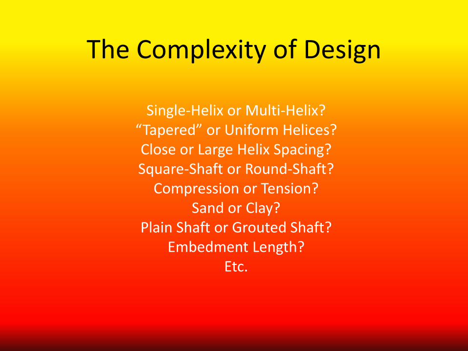
The Complexity of Design
Single-Helix or Multi-Helix? “Tapered” or Uniform Helices? Close or Large Helix Spacing? Square-Shaft or Round-Shaft?
Compression or Tension? Sand or Clay?
Plain Shaft or Grouted Shaft? Embedment Length?
Etc.
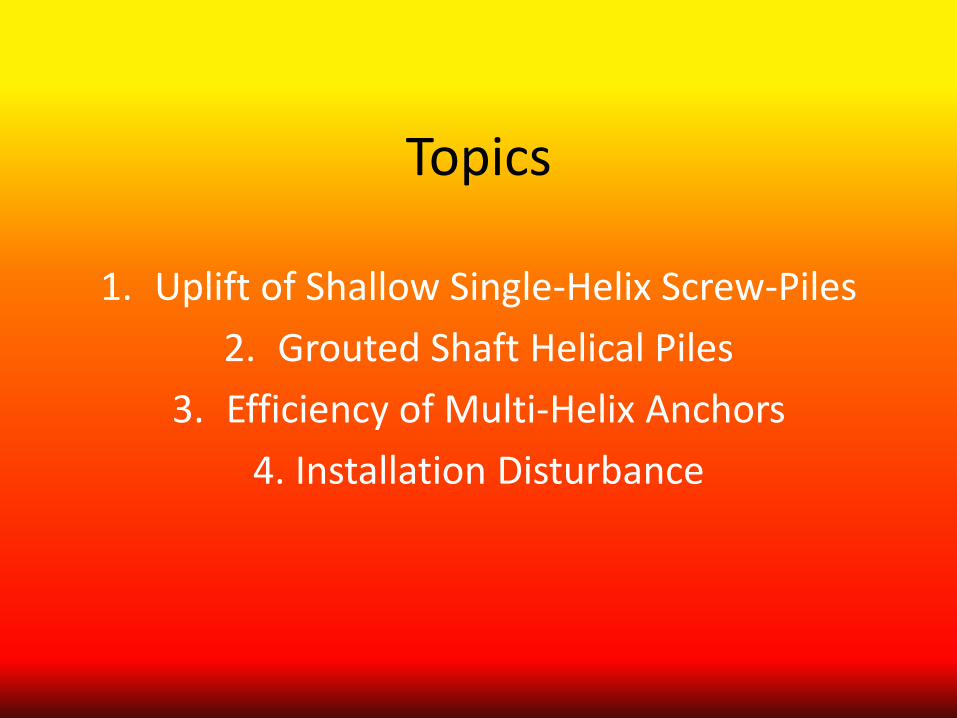
Topics
1. Uplift of Shallow Single-Helix Screw-Piles 2. Grouted Shaft Helical Piles
3. Efficiency of Multi-Helix Anchors 4. Installation Disturbance
1. Uplift Behavior of Shallow Single-Helix Screw-Piles

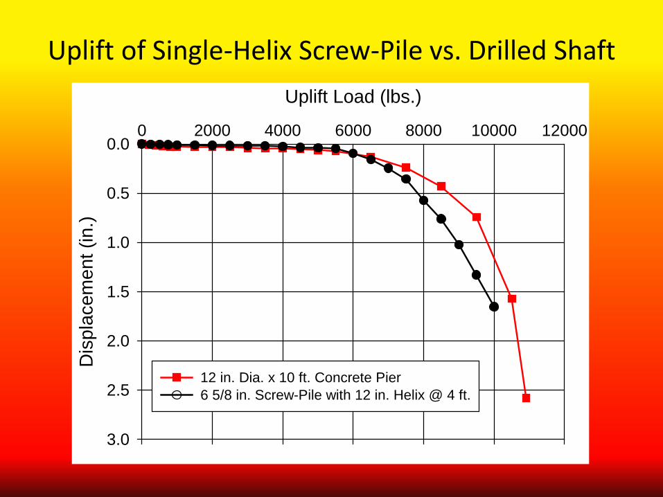
Uplift of Single-Helix Screw-Pile vs. Drilled Shaft Uplift Load (lbs.)
0 2000 4000 6000 8000 10000 12000
Dis
plac
emen
t (in
.)
0.0
0.5
1.0
1.5
2.0
2.5
3.0
12 in. Dia. x 10 ft. Concrete Pier6 5/8 in. Screw-Pile with 12 in. Helix @ 4 ft.
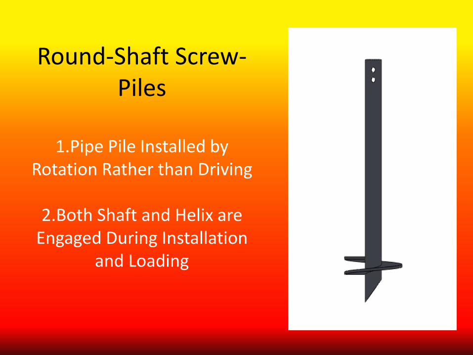
Round-Shaft Screw-Piles
1.Pipe Pile Installed by
Rotation Rather than Driving
2.Both Shaft and Helix are Engaged During Installation
and Loading
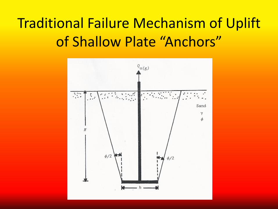
Traditional Failure Mechanism of Uplift of Shallow Plate “Anchors”
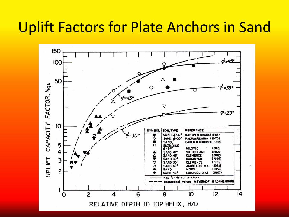
Uplift Factors for Plate Anchors in Sand
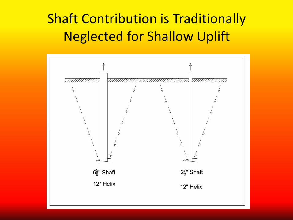
Shaft Contribution is Traditionally Neglected for Shallow Uplift
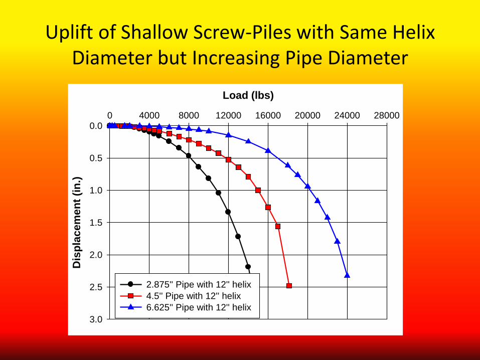
Uplift of Shallow Screw-Piles with Same Helix Diameter but Increasing Pipe Diameter
Load (lbs)
0 4000 8000 12000 16000 20000 24000 28000
Dis
plac
emen
t (in
.)
0.0
0.5
1.0
1.5
2.0
2.5
3.0
2.875'' Pipe with 12'' helix 4.5'' Pipe with 12'' helix 6.625'' Pipe with 12'' helix
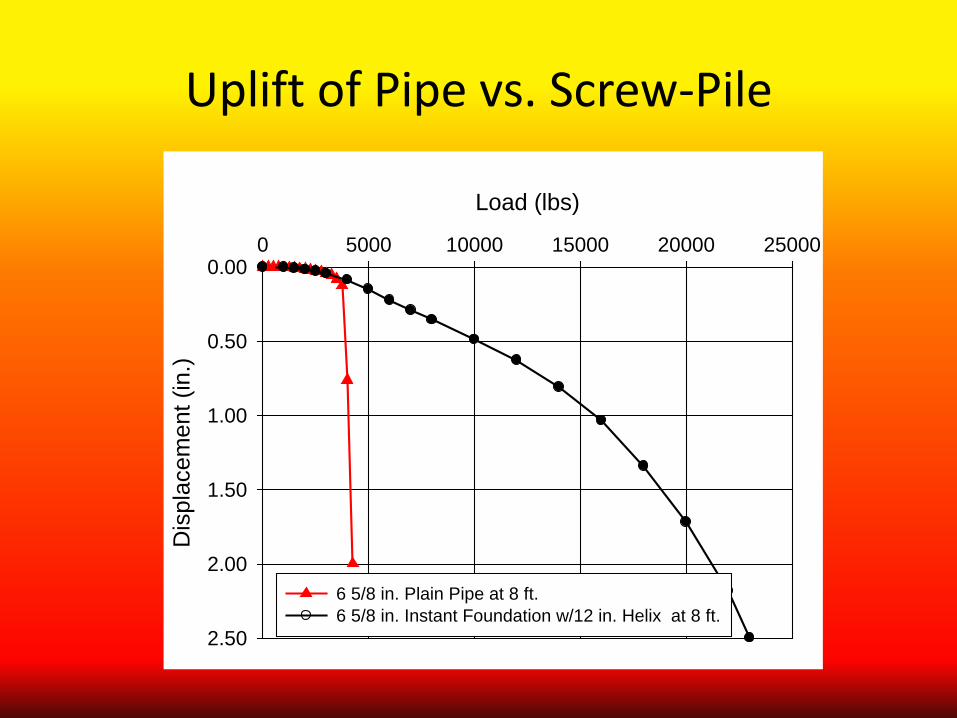
Uplift of Pipe vs. Screw-Pile
Load (lbs)
0 5000 10000 15000 20000 25000
Dis
plac
emen
t (in
.)
0.00
0.50
1.00
1.50
2.00
2.50
6 5/8 in. Plain Pipe at 8 ft. 6 5/8 in. Instant Foundation w/12 in. Helix at 8 ft.
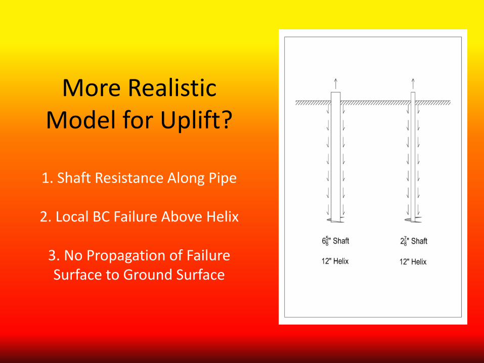
More Realistic Model for Uplift?
1. Shaft Resistance Along Pipe
2. Local BC Failure Above Helix
3. No Propagation of Failure Surface to Ground Surface
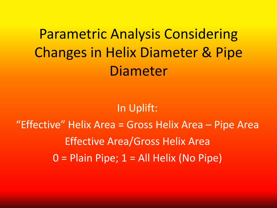
Parametric Analysis Considering Changes in Helix Diameter & Pipe
Diameter
In Uplift: “Effective” Helix Area = Gross Helix Area – Pipe Area
Effective Area/Gross Helix Area 0 = Plain Pipe; 1 = All Helix (No Pipe)
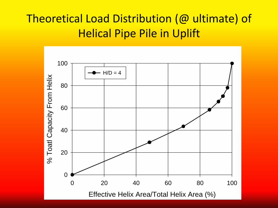
Theoretical Load Distribution (@ ultimate) of Helical Pipe Pile in Uplift
Effective Helix Area/Total Helix Area (%)0 20 40 60 80 100
% T
oatl
Cap
acity
Fro
m H
elix
0
20
40
60
80
100H/D = 4
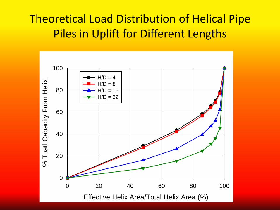
Theoretical Load Distribution of Helical Pipe Piles in Uplift for Different Lengths
Effective Helix Area/Total Helix Area (%)0 20 40 60 80 100
% T
oatl
Cap
acity
Fro
m H
elix
0
20
40
60
80
100H/D = 4 H/D = 8H/D = 16H/D = 32
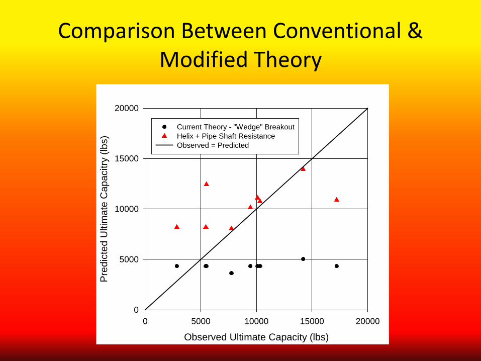
Comparison Between Conventional & Modified Theory
Observed Ultimate Capacity (lbs)0 5000 10000 15000 20000
Pred
icte
d U
ltim
ate
Cap
acitr
y (lb
s)
0
5000
10000
15000
20000
Current Theory - "Wedge" BreakoutHelix + Pipe Shaft ResistanceObserved = Predicted
Where are We Headed?
1. Refinement of Model for Shallow Uplift of Screw-Piles to Consider Shaft Resistance
2. Separation of Shaft and End Capacity at
Different Levels of Load
1. Summary We Need to Rethink How Round Shaft Screw-Piles
(Helical Pipe Piles) Behave in Uplift
1. Design the Helix Capacity Using Traditional Bearing Capacity Theory
2. Design the Shaft Capacity Using Traditional Approaches for Pipe Piles (e.g., Alpha or Beta
Methods) with Consideration for Pipe Plugging
2. Grouted Shaft Helical Piles
A Screw-Pile or Helical Anchor with a Central Steel Shaft Surrounded by PC Grout
Helical Pulldown Micropiles (HPMP)
& Helical Cast-in-Place Displacement Piles
(HCIPDP) (Similar to ACIPD Piles)
• What is the Contribution of the Shaft to Total Capacity? In Compression? In Tension?
• Can We Estimate Shaft Capacity from Installation Parameters?
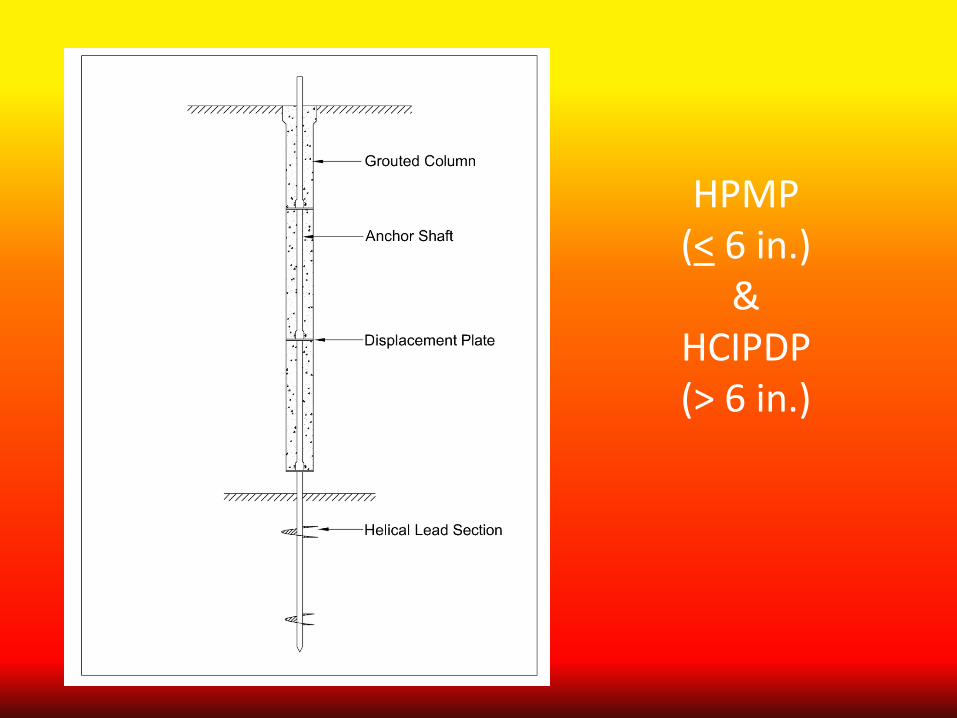
HPMP (< 6 in.)
& HCIPDP (> 6 in.)
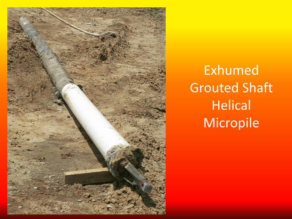
Exhumed Grouted Shaft
Helical Micropile

Is a Grouted Shaft Helical Pile/Anchor a Structural Element
or a Geotechnical Element?
Depends!
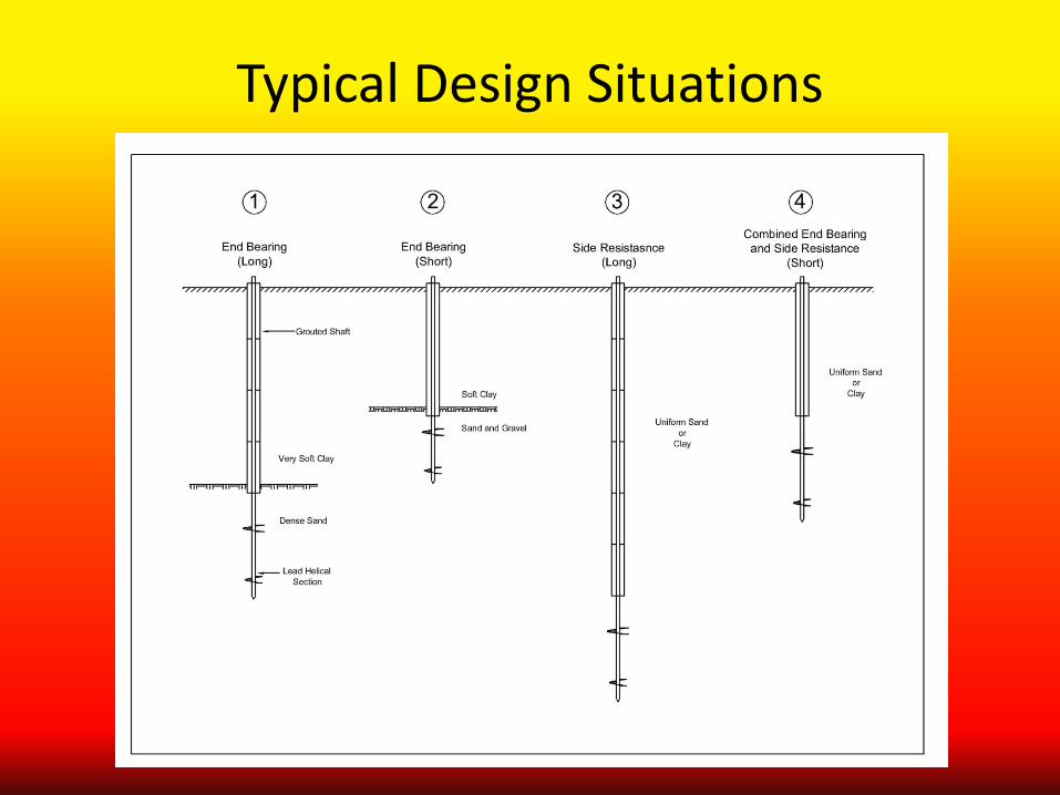
Typical Design Situations
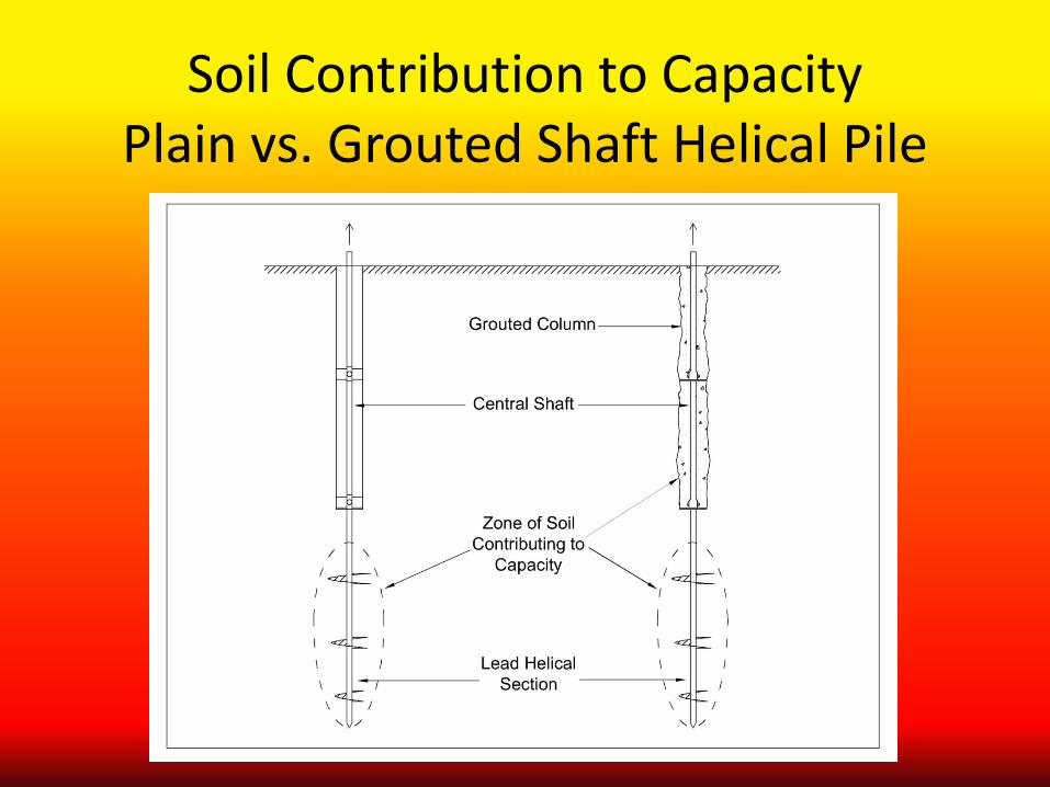
Soil Contribution to Capacity Plain vs. Grouted Shaft Helical Pile
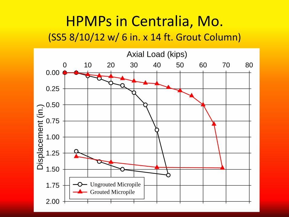
HPMPs in Centralia, Mo. (SS5 8/10/12 w/ 6 in. x 14 ft. Grout Column)
Axial Load (kips)0 10 20 30 40 50 60 70 80
Dis
plac
emen
t (in
.)
0.00
0.25
0.50
0.75
1.00
1.25
1.50
1.75
2.00
Ungrouted MicropileGrouted Micropile
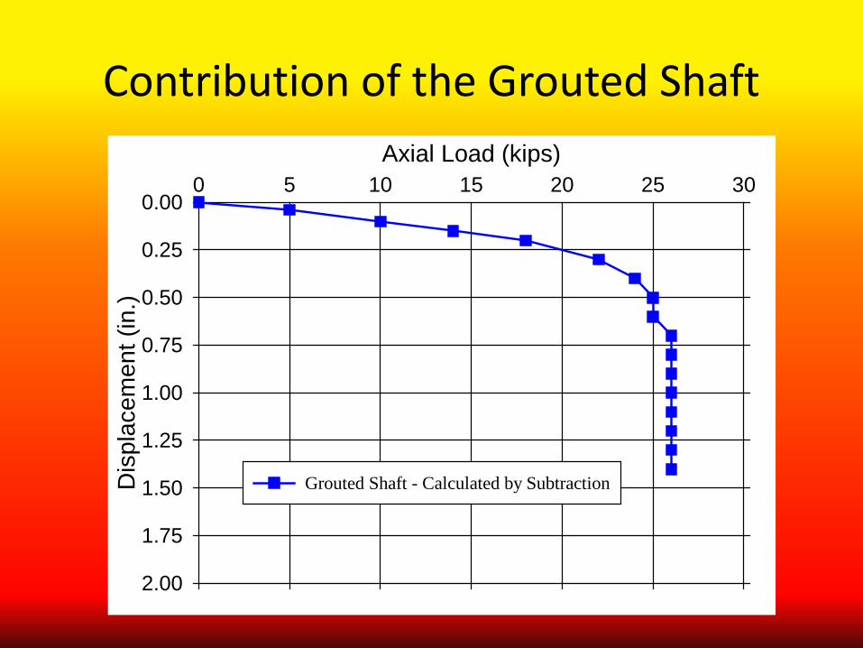
Contribution of the Grouted Shaft Axial Load (kips)
0 5 10 15 20 25 30
Dis
plac
emen
t (in
.)
0.00
0.25
0.50
0.75
1.00
1.25
1.50
1.75
2.00
Grouted Shaft - Calculated by Subtraction
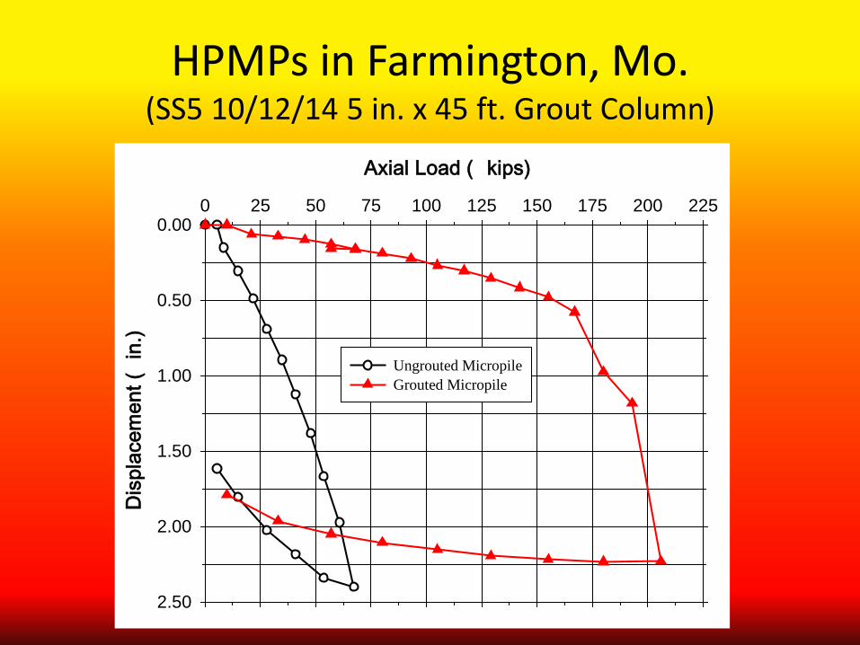
HPMPs in Farmington, Mo. (SS5 10/12/14 5 in. x 45 ft. Grout Column)
Axial Load ( kips)
0 25 50 75 100 125 150 175 200 225
Dis
plac
emen
t (in
.)
0.00
0.50
1.00
1.50
2.00
2.50
Ungrouted MicropileGrouted Micropile
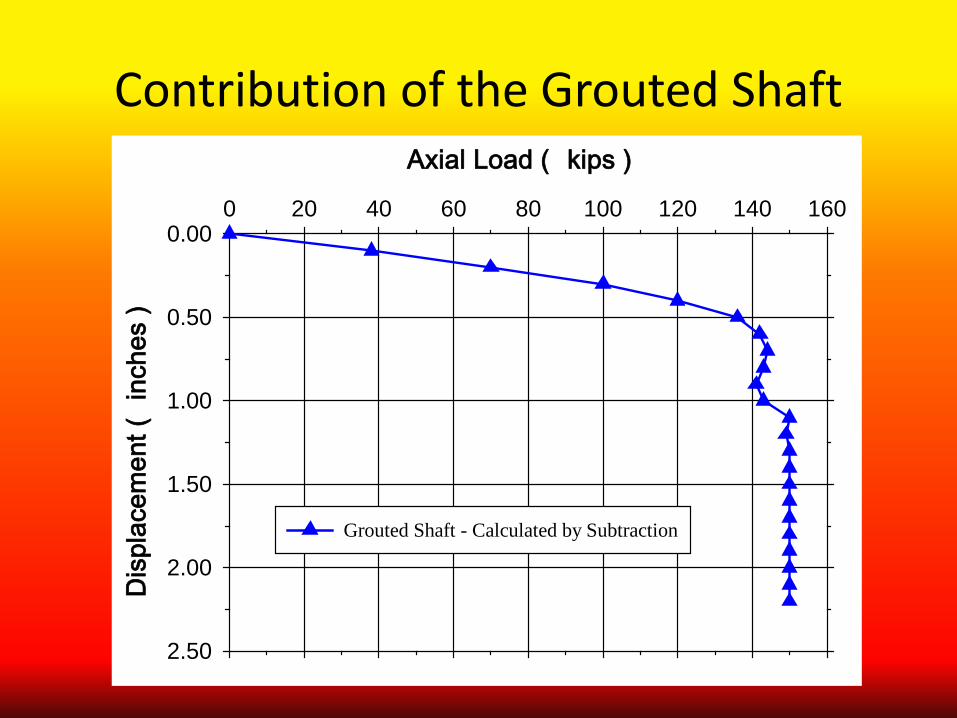
Contribution of the Grouted Shaft Axial Load ( kips )
0 20 40 60 80 100 120 140 160
Dis
plac
emen
t (in
ches
)
0.00
0.50
1.00
1.50
2.00
2.50
Grouted Shaft - Calculated by Subtraction
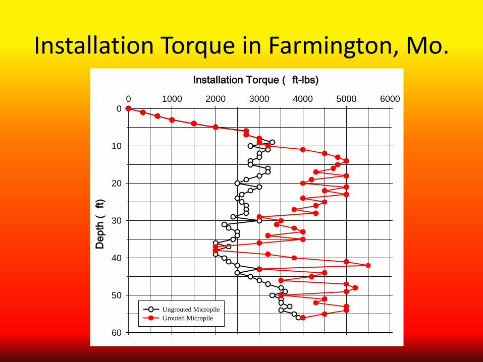
Installation Torque in Farmington, Mo. Installation Torque ( ft-lbs)
0 1000 2000 3000 4000 5000 6000D
epth
(ft)
0
10
20
30
40
50
60
Ungrouted MicropileGrouted Micropile
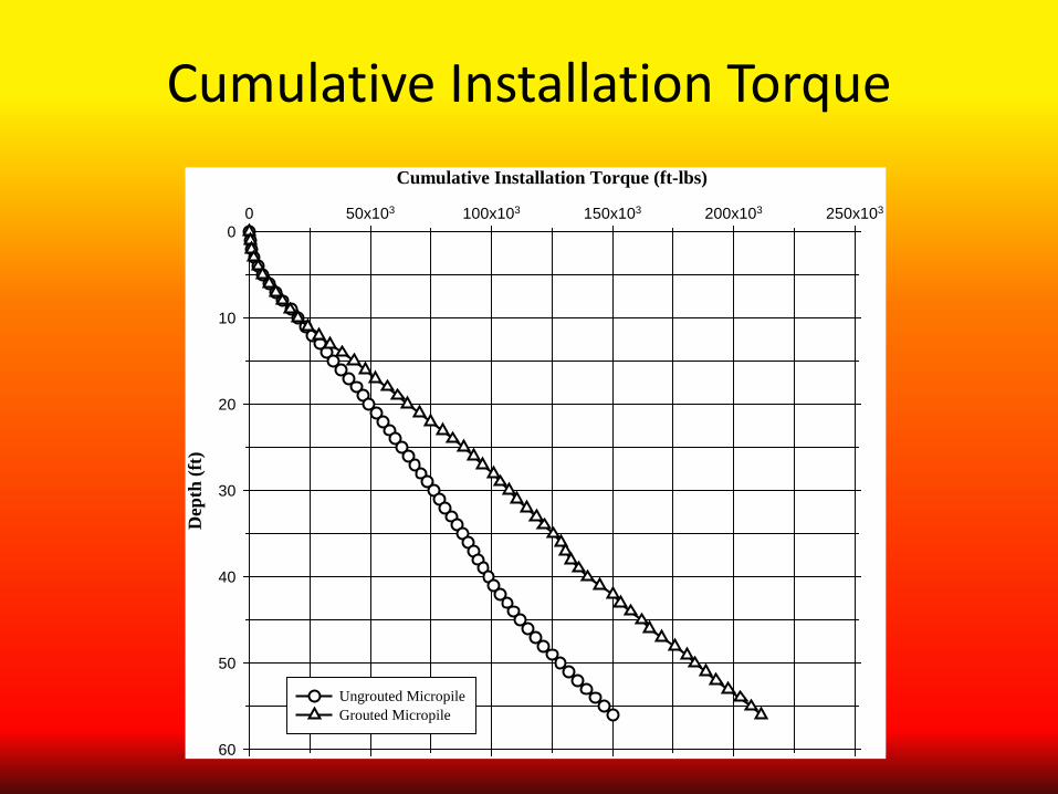
Cumulative Installation Torque Cumulative Installation Torque (ft-lbs)
0 50x103 100x103 150x103 200x103 250x103D
epth
(ft)
0
10
20
30
40
50
60
Ungrouted MicropileGrouted Micropile
Load Distribution in Deep Foundations (% End vs. % Side)
Depends on: Pile Type & Use
Installation Method Geometry (L/D)
Soil Type Stratigraphy
Load Level (Relative to Ultimate) End and Side Don’t Develop Capacity at the Same Rate
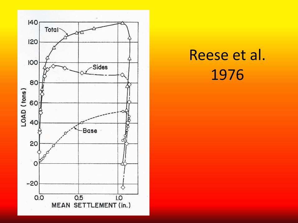
Reese et al. 1976
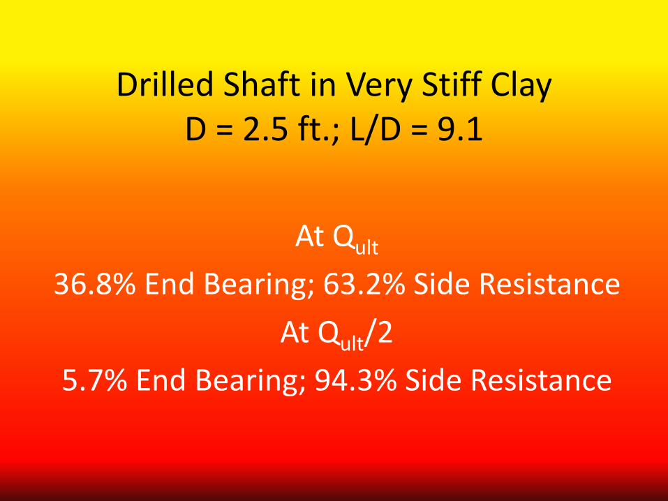
Drilled Shaft in Very Stiff Clay D = 2.5 ft.; L/D = 9.1
At Qult
36.8% End Bearing; 63.2% Side Resistance At Qult/2
5.7% End Bearing; 94.3% Side Resistance
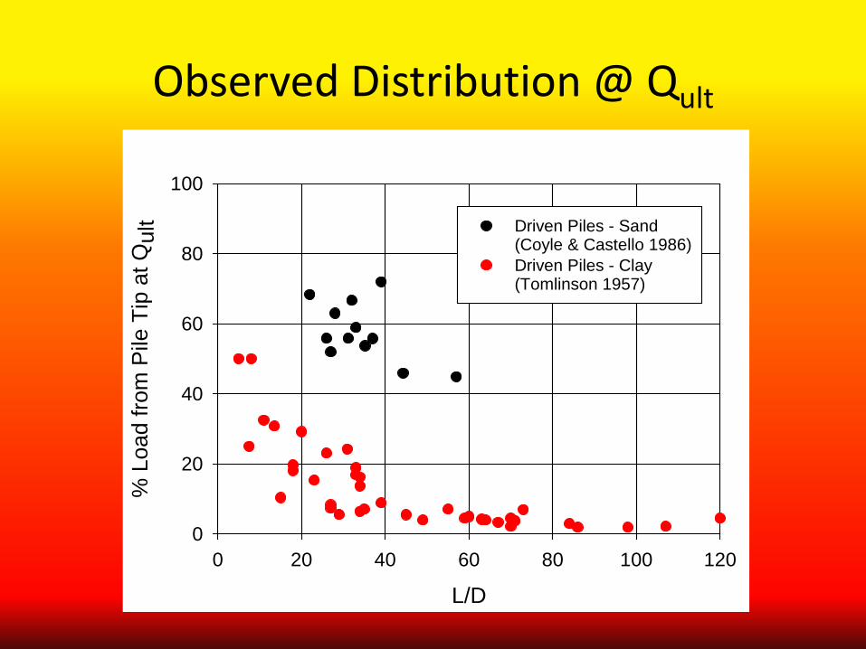
Observed Distribution @ Qult
L/D0 20 40 60 80 100 120
% L
oad
from
Pile
Tip
at Q
ult
0
20
40
60
80
100
Driven Piles - Sand(Coyle & Castello 1986)Driven Piles - Clay(Tomlinson 1957)
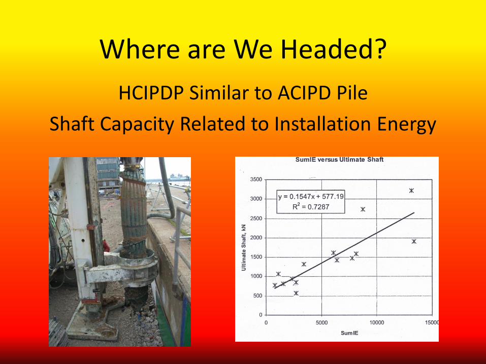
Where are We Headed? HCIPDP Similar to ACIPD Pile
Shaft Capacity Related to Installation Energy
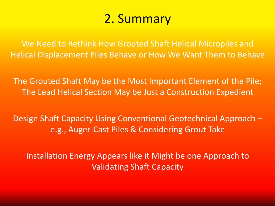
2. Summary
We Need to Rethink How Grouted Shaft Helical Micropiles and Helical Displacement Piles Behave or How We Want Them to Behave
The Grouted Shaft May be the Most Important Element of the Pile;
The Lead Helical Section May be Just a Construction Expedient
Design Shaft Capacity Using Conventional Geotechnical Approach – e.g., Auger-Cast Piles & Considering Grout Take
Installation Energy Appears like it Might be one Approach to
Validating Shaft Capacity
3. & 4. Efficiency of Multi-Helix Anchors & Installation Disturbance
Why do We Suspect that Colinear Multi-Helix Piles/Anchors May not be 100% Efficient?
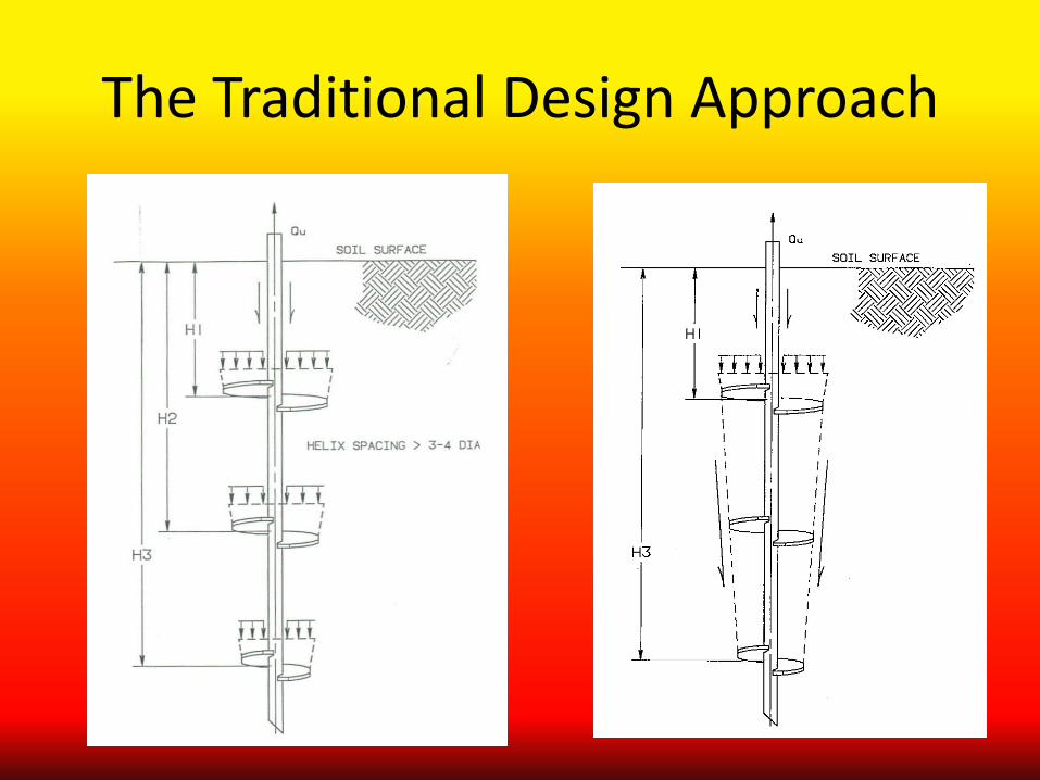
The Traditional Design Approach

e.g., Canadian Foundation Manual
Qh = Ah(suNu + γDbNq + 0.5γBNγ)
What’s Important in This Equation? Sands: Ø’ & γ
Clays: su
Qt = ∑Qh

Where Might we Expect Installation Disturbance and a Reduction in
Efficiency?
“Structured” Soils “Cemented” Soils “Sensitive” Soils
Dense Sands All Soils?
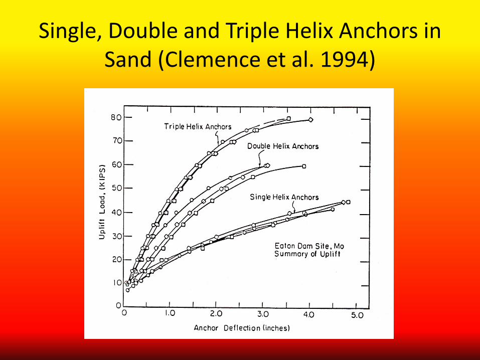
Single, Double and Triple Helix Anchors in Sand (Clemence et al. 1994)
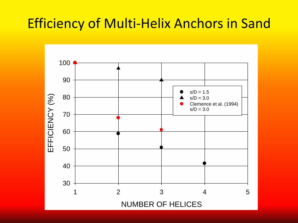
Efficiency of Multi-Helix Anchors in Sand
NUMBER OF HELICES1 2 3 4 5
EFF
ICIE
NC
Y (%
)
30
40
50
60
70
80
90
100
s/D = 1.5s/D = 3.0Clemence et al. (1994)s/D = 3.0
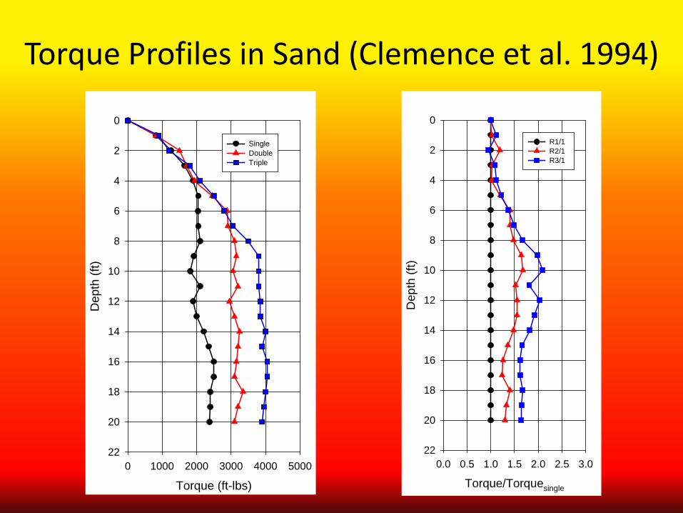
Torque Profiles in Sand (Clemence et al. 1994)
Torque (ft-lbs)0 1000 2000 3000 4000 5000
Dep
th (f
t)
0
2
4
6
8
10
12
14
16
18
20
22
Single DoubleTriple
Torque/Torquesingle
0.0 0.5 1.0 1.5 2.0 2.5 3.0
Dep
th (f
t)
0
2
4
6
8
10
12
14
16
18
20
22
R1/1 R2/1 R3/1
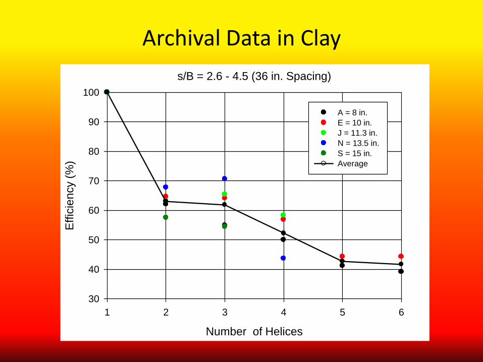
Archival Data in Clay s/B = 2.6 - 4.5 (36 in. Spacing)
Number of Helices
1 2 3 4 5 6
Effic
ienc
y (%
)
30
40
50
60
70
80
90
100
A = 8 in. E = 10 in. J = 11.3 in. N = 13.5 in. S = 15 in. Average
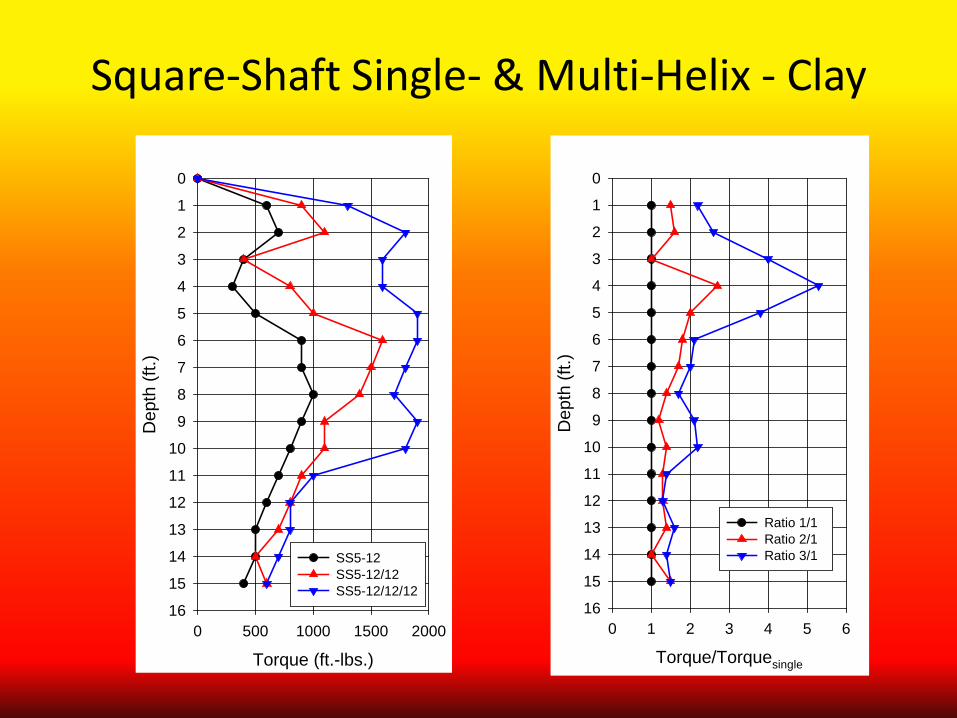
Square-Shaft Single- & Multi-Helix - Clay
Torque (ft.-lbs.)0 500 1000 1500 2000
Dep
th (f
t.)0
1
2
3
4
5
6
7
8
9
10
11
12
13
14
15
16
SS5-12SS5-12/12SS5-12/12/12
Torque/Torquesingle
0 1 2 3 4 5 6
Dep
th (f
t.)
0
1
2
3
4
5
6
7
8
9
10
11
12
13
14
15
16
Ratio 1/1 Ratio 2/1 Ratio 3/1
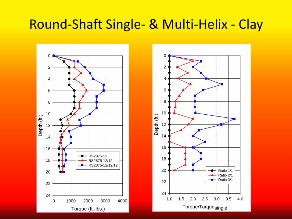
Round-Shaft Single- & Multi-Helix - Clay
Torque (ft.-lbs.)0 1000 2000 3000 4000
Dep
th (f
t.)
0
2
4
6
8
10
12
14
16
18
20
22
24
RS2875-12RS2875-12/12RS2875-12/12/12
Torque/Torquesingle
1.0 1.5 2.0 2.5 3.0 3.5 4.0
Dep
th (f
t.)
0
2
4
6
8
10
12
14
16
18
20
22
24
Ratio 1/1Ratio 2/1Ratio 3/1
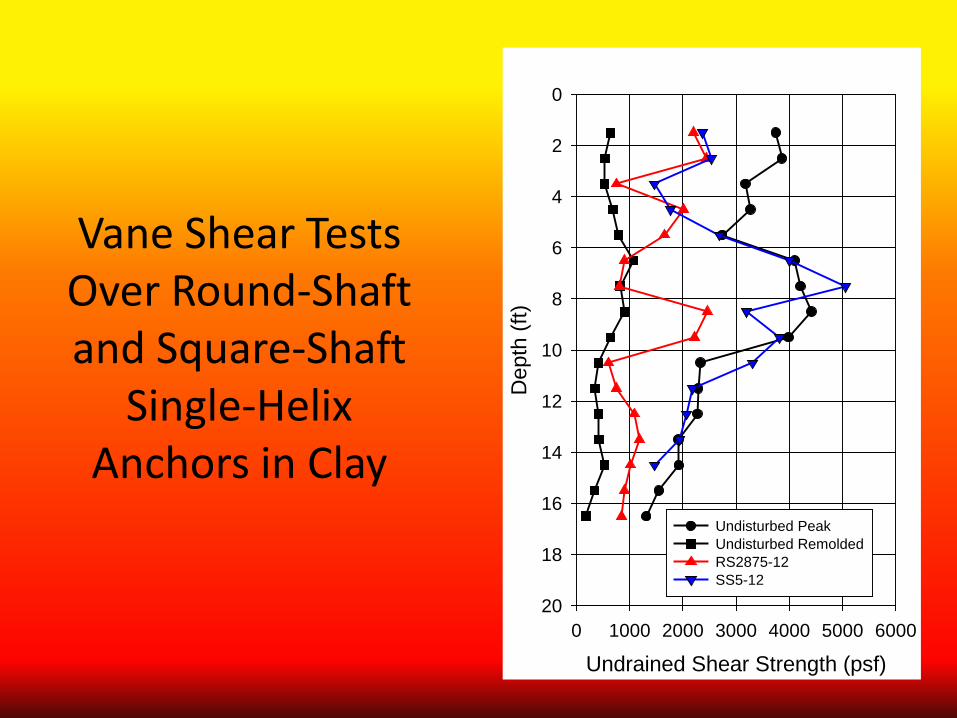
Vane Shear Tests Over Round-Shaft and Square-Shaft
Single-Helix Anchors in Clay
Undrained Shear Strength (psf)0 1000 2000 3000 4000 5000 6000
Dep
th (f
t)
0
2
4
6
8
10
12
14
16
18
20
Undisturbed PeakUndisturbed RemoldedRS2875-12 SS5-12
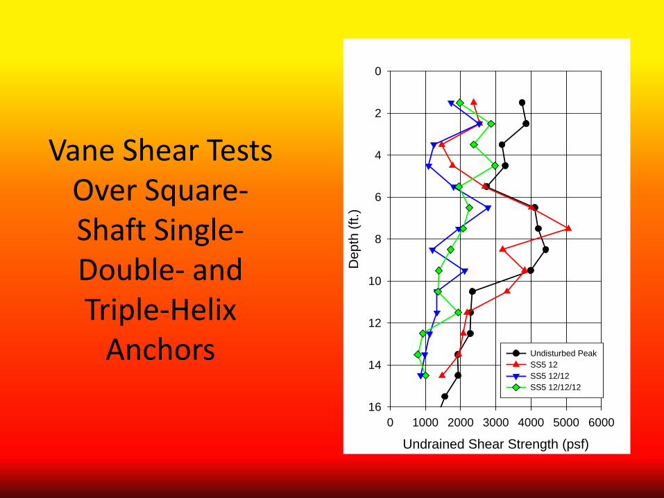
Vane Shear Tests Over Square-Shaft Single- Double- and Triple-Helix
Anchors
Undrained Shear Strength (psf)0 1000 2000 3000 4000 5000 6000
Dep
th (f
t.)
0
2
4
6
8
10
12
14
16
Undisturbed PeakSS5 12SS5 12/12 SS5 12/12/12

Canadian Foundation Manual
Qh = Ah(suNu + γDbNq + 0.5γBNγ)
For Clays We Need to Adjust su for Installation Disturbance if Everything Else is Constant
For Sands We May Need to Adjust Ø’
Or We Might Assign a “Local Efficiency” for Each Helix
Monitoring Installation
Installation Torque Installation Advance (rev/ft)
Installation Speed
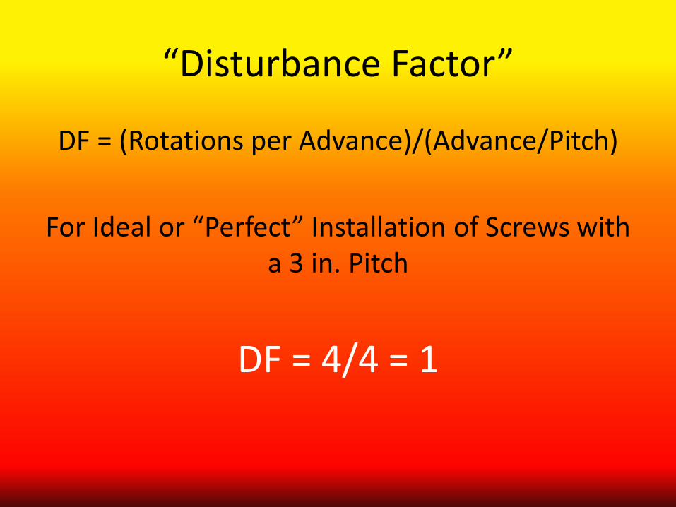
“Disturbance Factor”
DF = (Rotations per Advance)/(Advance/Pitch)
For Ideal or “Perfect” Installation of Screws with a 3 in. Pitch
DF = 4/4 = 1
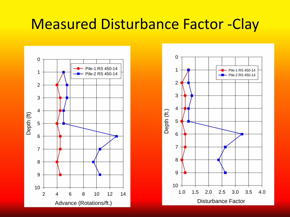
Measured Disturbance Factor -Clay
Disturbance Factor 1.0 1.5 2.0 2.5 3.0 3.5 4.0
Dep
th (f
t.)
0
1
2
3
4
5
6
7
8
9
10
Pile-1 RS 450-14Pile-2 RS 450-14
Advance (Rotations/ft.)2 4 6 8 10 12 14
Dep
th (f
t)
0
1
2
3
4
5
6
7
8
9
10
Pile-1 RS 450-14Pile-2 RS 450-14
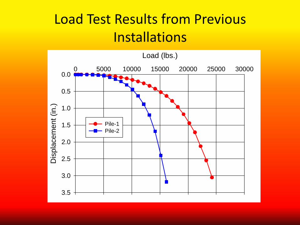
Load Test Results from Previous Installations
Load (lbs.)
0 5000 10000 15000 20000 25000 30000
Dis
plac
emen
t (in
.)
0.0
0.5
1.0
1.5
2.0
2.5
3.0
3.5
Pile-1Pile-2
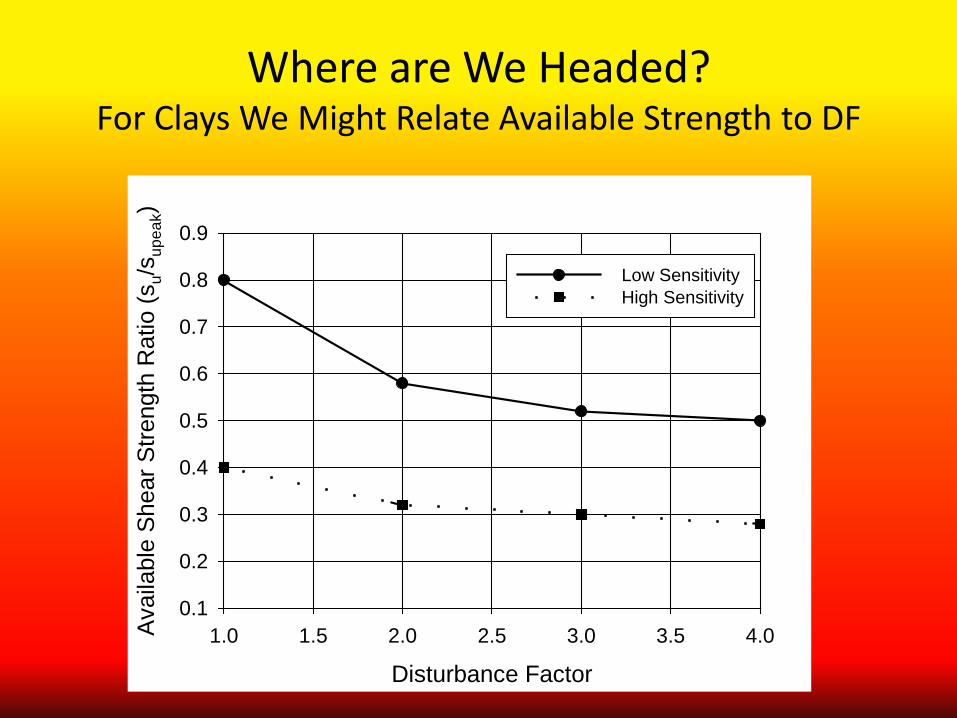
Where are We Headed? For Clays We Might Relate Available Strength to DF
Disturbance Factor1.0 1.5 2.0 2.5 3.0 3.5 4.0A
vaila
ble
She
ar S
treng
th R
atio
(su/s
upea
k)
0.1
0.2
0.3
0.4
0.5
0.6
0.7
0.8
0.9
Low SensitivityHigh Sensitivity
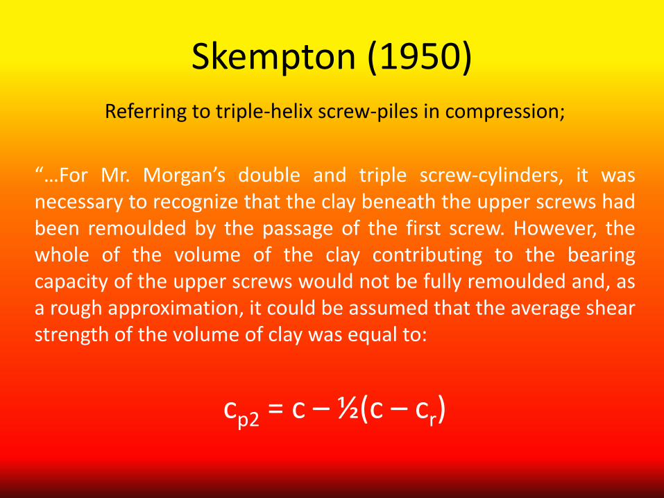
Skempton (1950) Referring to triple-helix screw-piles in compression;
“…For Mr. Morgan’s double and triple screw-cylinders, it was necessary to recognize that the clay beneath the upper screws had been remoulded by the passage of the first screw. However, the whole of the volume of the clay contributing to the bearing capacity of the upper screws would not be fully remoulded and, as a rough approximation, it could be assumed that the average shear strength of the volume of clay was equal to:
cp2 = c – ½(c – cr)

3. & 4. Summary
Installation of Screw-Piles and Helical Anchors Causes Disturbance to the Soil
The Degree of Disturbance will Depend on a Number of
Factors, Including: Soil Initial State
Sensitivity Installation Quality
Summary
1. The Behavior of Screw-Piles and Helical Anchors is More Complex that has Been Considered
2. The Failure Mechanisms Need to Consider the Specific Geometry and Soil Behavior
3. Installation Disturbance is Real and Should be Considered in Design
4. Design Methodologies will Need to Change to Reflect These Considerations
5. Installation Monitoring of both Torque and Advance is Essential

ISHF www.helicalfoundations.org