scenarios of earthquake and tsunami disaster including ... · scenarios of earthquake and tsunami...
TRANSCRIPT
SCENARIOS OF EARTHQUAKE AND TSUNAMI DISASTER INCLUDING DAMAGE TO ROAD BRIDGES
KATAOKA Shojiro1
Abstract
Disaster scenarios are now widely used for better understanding and disaster mitigation measures planning. There is, however, no established method of evaluating tsunami damage to road bridges that method can be used to develop a tsunami disaster scenario for road network. In this paper, a simple procedure is proposed for evaluation of tsunami damage to road bridges and its application to development of a disaster scenario is presented. The scenario includes damage to road bridges and embankments, and inundated road sections caused by a hypothetical Nankai earthquake and its tsunami. Introduction
Great earthquakes often have occurred at the boundaries of continental and oceanic plates around Japan. These earthquakes generate not only ground shaking but also tsunami and hence have caused severe disaster especially in the coastal area of Pacific Ocean. Scenarios of earthquake and tsunami disaster are useful for decision makers to plan disaster mitigation measures and for people to understand the disaster for which they must be prepared. Since there is limited but some time between earthquake occurrence and tsunami arrival, tsunami disaster scenarios are vital to consider in advance how to evacuate or response right after one feels ground shaking.
Disaster scenarios have been developed and widely used in local governments
these years but earthquake and tsunami damage to road networks are usually not taken into account. The reason is that there has been no established method of evaluating degree of damage to road bridges caused by tsunamis, whereas methods of evaluating seismic damage to road bridges and embankments, and tsunami damage to embankments are available (Kobayashi and Unjoh, 2005; Public Works Research Institute, 2003; Shuto, 1997).
In this paper, a simple procedure is proposed for evaluation of tsunami damage to
road bridges based on a series of wave channel experiments, followed by its application to development of an earthquake and tsunami disaster scenario. The scenario includes damage to road bridges and embankments, and inundated road sections caused by a hypothetical Nankai earthquake and its tsunami.
1 Senior Researcher, Earthquake Disaster Prevention Division, National Institute for Land and Infrastructure Management, Ministry of Land, Infrastructure and Transport
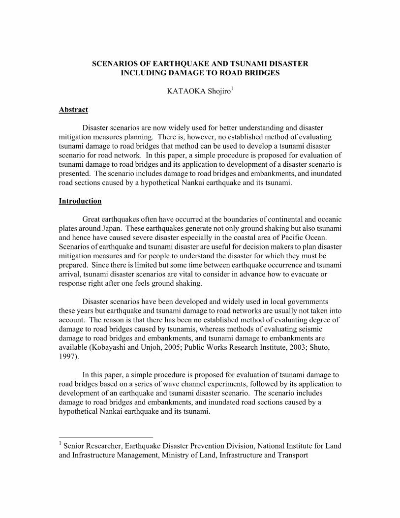
Wave Channel Experiments We conducted a series of experiment using a wave channel and bridge girder models to investigate wave force acts on a bridge girder struck by a tsunami. The experimental setup of one of the bridge girder models in the wave channel is shown in Figure 1. The wave channel is 140m long, 2m wide, and 5m deep. A fixed bed slope had been constructed and the bridge girder model, which is made of metal, was installed on the slope. As shown in Table 1, 15 combinations of still water level, h, and initial wave height, H0, of solitary wave are set and the experiment with each combination is executed three times.
Figure 1: Experimental setup of a bridge girder model in the wave channel (unit: mm).
Table 1: Still water level, h, set for each initial wave height, H0 H0 [cm] h [cm]
20 15, 30 30 7.5, 10, 12.5, 15, 30 40 7.5, 10, 12.5, 15, 17.5, 20, 22.5, 30
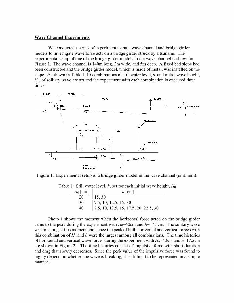
Photo 1 shows the moment when the horizontal force acted on the bridge girder came to the peak during the experiment with H0=40cm and h=17.5cm. The solitary wave was breaking at this moment and hence the peak of both horizontal and vertical forces with this combination of H0 and h were the largest among all combinations. The time histories of horizontal and vertical wave forces during the experiment with H0=40cm and h=17.5cm are shown in Figure 2. The time histories consist of impulsive force with short duration and drag that slowly decreases. Since the peak value of the impulsive force was found to highly depend on whether the wave is breaking, it is difficult to be represented in a simple manner.
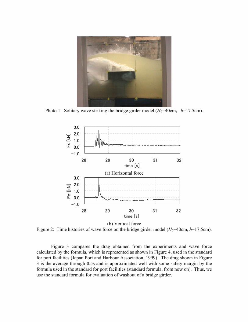
Photo 1: Solitary wave striking the bridge girder model (H0=40cm,h=17.5cm).
-1.0
0.0
1.0
2.0
3.0
28 29 30 31 32time [s]
Fx
[kN
]
(a) Horizontal force
-1.0
0.0
1.0
2.0
3.0
28 29 30 31 32time [s]
Fz [
kN]
(b) Vertical force
Figure 2: Time histories of wave force on the bridge girder model (H0=40cm, h=17.5cm).
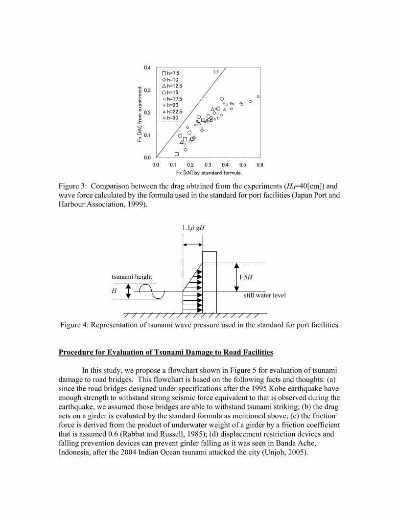
Figure 3 compares the drag obtained from the experiments and wave force calculated by the formula, which is represented as shown in Figure 4, used in the standard for port facilities (Japan Port and Harbour Association, 1999). The drag shown in Figure 3 is the average through 0.5s and is approximated well with some safety margin by the formula used in the standard for port facilities (standard formula, from now on). Thus, we use the standard formula for evaluation of washout of a bridge girder.
0.0
0.1
0.2
0.3
0.4
0.0 0.1 0.2 0.3 0.4 0.5 0.6
Fx [kN] by standard formula
Fx
[kN
] fr
om e
xper
imen
t
h=7.5h=10h=12.5h=15h=17.5h=20h=22.5h=30
1:1
Figure 3: Comparison between the drag obtained from the experiments (H0=40[cm]) and wave force calculated by the formula used in the standard for port facilities (Japan Port and Harbour Association, 1999).
H
1.5H
1.1ρ gH
still water level
tsunami height
Figure 4: Representation of tsunami wave pressure used in the standard for port facilities Procedure for Evaluation of Tsunami Damage to Road Facilities In this study, we propose a flowchart shown in Figure 5 for evaluation of tsunami damage to road bridges. This flowchart is based on the following facts and thoughts: (a) since the road bridges designed under specifications after the 1995 Kobe earthquake have enough strength to withstand strong seismic force equivalent to that is observed during the earthquake, we assumed those bridges are able to withstand tsunami striking; (b) the drag acts on a girder is evaluated by the standard formula as mentioned above; (c) the friction force is derived from the product of underwater weight of a girder by a friction coefficient that is assumed 0.6 (Rabbat and Russell, 1985); (d) displacement restriction devices and falling prevention devices can prevent girder falling as it was seen in Banda Ache, Indonesia, after the 2004 Indian Ocean tsunami attacked the city (Unjoh, 2005).
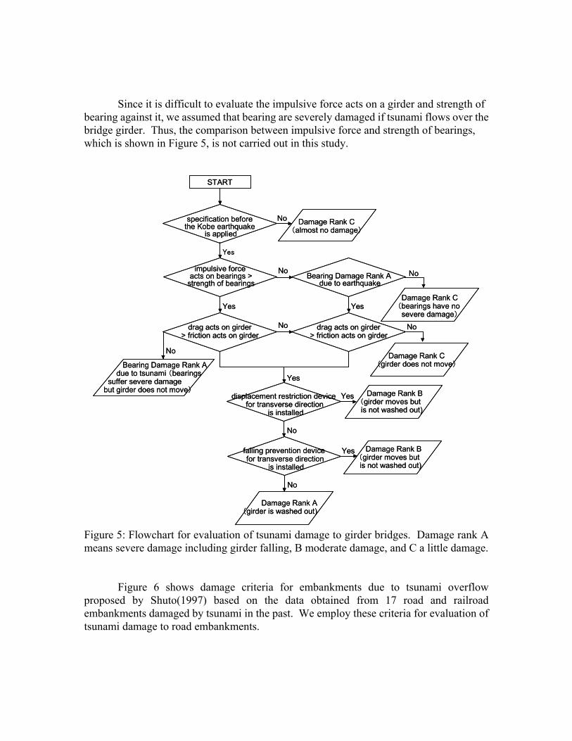
Since it is difficult to evaluate the impulsive force acts on a girder and strength of
bearing against it, we assumed that bearing are severely damaged if tsunami flows over the bridge girder. Thus, the comparison between impulsive force and strength of bearings, which is shown in Figure 5, is not carried out in this study.
impulsive force acts on bearings >
strength of bearingsNo
START
Bearing Damage Rank Adue to earthquake
Yes Yes
drag acts on girder> friction acts on girder
Yes
Yes
No
Yes
No
No
No
No
specification beforethe Kobe earthquake
is applied
Yes
No Damage Rank C(almost no damage)
Damage Rank C(bearings have no severe damage)
Bearing Damage Rank Adue to tsunami (bearings
suffer severe damagebut girder does not move)
drag acts on girder> friction acts on girder
Damage Rank C(girder does not move)
No
Damage Rank B(girder moves but is not washed out)
Damage Rank B(girder moves but is not washed out)
displacement restriction device for transverse direction
is installed
falling prevention device for transverse direction
is installed
Damage Rank A(girder is washed out)
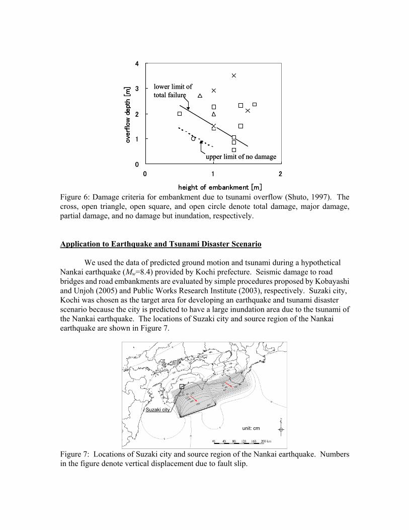
Figure 5: Flowchart for evaluation of tsunami damage to girder bridges. Damage rank A means severe damage including girder falling, B moderate damage, and C a little damage. Figure 6 shows damage criteria for embankments due to tsunami overflow proposed by Shuto(1997) based on the data obtained from 17 road and railroad embankments damaged by tsunami in the past. We employ these criteria for evaluation of tsunami damage to road embankments.
0
1
2
3
4
0 1 2
height of embankment [m]
overf
low
dept
h [
m] lower limit of
total failure
upper limit of no damage0
1
2
3
4
0 1 2
height of embankment [m]
overf
low
dept
h [
m] lower limit of
total failure
upper limit of no damage
Figure 6: Damage criteria for embankment due to tsunami overflow (Shuto, 1997). The cross, open triangle, open square, and open circle denote total damage, major damage, partial damage, and no damage but inundation, respectively. Application to Earthquake and Tsunami Disaster Scenario
We used the data of predicted ground motion and tsunami during a hypothetical Nankai earthquake (Mw=8.4) provided by Kochi prefecture. Seismic damage to road bridges and road embankments are evaluated by simple procedures proposed by Kobayashi and Unjoh (2005) and Public Works Research Institute (2003), respectively. Suzaki city, Kochi was chosen as the target area for developing an earthquake and tsunami disaster scenario because the city is predicted to have a large inundation area due to the tsunami of the Nankai earthquake. The locations of Suzaki city and source region of the Nankai earthquake are shown in Figure 7.
Suzaki city
unit: cm
Suzaki city
unit: cm
Figure 7: Locations of Suzaki city and source region of the Nankai earthquake. Numbers in the figure denote vertical displacement due to fault slip.
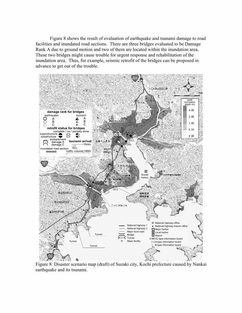
Figure 8 shows the result of evaluation of earthquake and tsunami damage to road facilities and inundated road sections. There are three bridges evaluated to be Damage Rank A due to ground motion and two of them are located within the inundation area. These two bridges might cause trouble for urgent response and rehabilitation of the inundation area. Thus, for example, seismic retrofit of the bridges can be proposed in advance to get out of the trouble.
damage rank for bridgesearthquake tsunami
ABC
ABC
retrofit status for bridges
superstructuresubstructure
complete / no / partially done
tsunami arrival10min.
00m
traffic volume(1999)inundated road section
embankment damage Adamage C
5m
10m
20m
20m
10m
25m
25m
<5m
20m
Tunnel
Tunnel
Tunnel
National highway 1National highway 2Major local roadBridgeTunnelMajor facility
National highway officeNational highway branch officeMajor harborLocal harborAirportHL-type information boardA-type information boardB-type information board
40m
5m
5m
15m 10m
5m
15m
peak inundation depth (m)
SuzakiHarbor
Figure 8: Disaster scenario map (draft) of Suzaki city, Kochi prefecture caused by Nankai earthquake and its tsunami.

Closing Remarks In this paper, an earthquake and tsunami disaster scenario that includes damage to a road network is presented. We have been studying the procedure for developing an integrated disaster scenario map that includes damage to coastal, port, and river facilities besides road facilities. The integrated map is expected to help us to develop a standard procedure for planning comprehensive earthquake and tsunami disaster measures, taking account of various possible problems. Acknowledgments
Risk Management Division of Kochi Prefecture provided the predicted ground motion and tsunami data. Shikoku Regional Development Bureau and Tosa National Highway Office provided the data of the road facilities under their administration. I deeply appreciate their kind cooperation. References Japan Port and Harbour Association (1999): Technical standards and commentaries of port
and harbour facilities. Kobayashi, H. and Unjoh, S. (2005): Development of simplified seismic damage
assessment method of road bridges based on past damage experiences, Doboku Gijutsu Shiryou (Civil Engineering Journal), Vol. 47, No. 12, pp. 48-53.
Public Works Research Institute (2003): A simple method for evaluation of seismic performance of road embankments (draft).
Rabbat, B. G. and Russell, H. G. (1985): Friction coefficient of steel on concrete or grout, J. Struct. Eng., ASCE, Vol. 111, No. 3, pp. 505-515.
Shuto, N. (1997): On traffic disorder after a tsunami attack, Tsunami Engineering Technical Report, No. 14, pp. 1-31.
Unjoh, S. (2005): Damage to transportation facilities, The damage induced by Sumatra earthquake and associated tsunami of December 26, 2004, pp. 66-76, http://www.jsce.or.jp/committee/2004sumatra/report.htm

KATAOKA Shojiro Senior Researcher, Earthquake Disaster Prevention Division National Institute for Land and Infrastructure Management Ministry of Land, Infrastructure and Transport Office Address: 1 Asahi Tsukuba 305-0804, Japan Ph: +81-29-864-7682 FAX: +81-29-864-0598 Email: [email protected] Research and Academic Interests Evaluation of: Design seismic ground motion, Seismic hazards (strong motion, surface fault rupture, tsunami), Earthquake and tsunami damage to public works Degrees and Recent Professional Experiences 1996 Doctor of Engineering, Tokyo Institute of Technology 1994-1997 Research Fellow of the Japan Society for the Promotion of Science 1996-1997 Postdoctoral Scholar, California Institute of Technology 1997-1998 Lecturer, Tokyo Institute of Technology 1998-2001 Research Engineer, Ground Vibration Division, PWRI, MOC 2001-2002 Researcher, Earthquake Disaster Prevention Division, NILIM, MLIT 2002- Senior Researcher, ditto. Professional Service (or Memberships and Affiliations) Member of Japan Society of Civil Engineers Member of Seismological Society of Japan Member of Japan Association for Earthquake Engineering Member of the Headquarters for Earthquake Research Promotion Honors and Awards -1998 Tejima Doctoral Dissertation Award, Tejima Seiichi Commemorative Foundation Selected Publications 1. Kataoka, S. (1999): A 3-D FE-BE method for dynamic response analysis of dam-foundation-
reservoir systems, UJNR/JSDE Workshop on Earthquake Engineering for Dams. 2. Kataoka, S. (2000): Modeling the ground motion during the 1995 Hyogo-ken Nanbu earthquake
by a 3-D BEM, Proc. 12th World Conf. Earthq. Eng. 3. Kataoka, S. et al. (2002): A practical procedure for formulating level 2 earthquake motions
based on scenario earthquakes, Proc. 34th Joint Meeting of U.S.-Japan Panel on Wind and Seismic Effects, UJNR.
4. Kataoka, S. and Kusakabe, T. (2005): Characteristics of surface fault rupture relating to magnitude and slip type of inland earthquakes, Proc. JSCE, No. 801/I-73.
5. Kataoka, S. et al. (2006): Attenuation relationships of ground motion intensity using short period level as a variable, Proc. JSCE A, Vol. 62, No. 4.