satellite communications · satellite introduction satellite: in astronomical terms, a satellite is...
TRANSCRIPT

IV B.TECH II Sem-ECE-R15
Prepared by
Ms.G.Bhavana, Asst.Professsor
Ms.U.Dhanalakshmi, Asst.Professsor
INSTITUTE OF AERONAUTICAL ENGINEERING
(Autonomous)
DUNDIGAL, HYDERABAD - 500043
Satellite Communications

UNIT 1
Communication satellites

Satellite CommunicationsIntroduction and Historical Background

Satellite Introduction
Satellite: In astronomical terms, asatellite is a celestial body that orbitsaround a planet.
Example: The moon is a satellite of Earth.
In aerospace terms, a satellite is a space vehicle launched by humans and orbits around Earth or another celestial body.

Introduction
Communications Satellite: It is a microwaverepeater in the sky that consists of a diversecombination of one or more components includingtransmitter, receiver, amplifier, regenerator, filteronboard computer, multiplexer, demultiplexer,antenna, waveguide etc.
A satellite radio repeater is also calledtransponder. This is usually a combination oftransmitter and receiver.

What is a satellite system?
A satellite system consists of one or more satellites, a ground-based station to control the operation of the system, and a user network earth stations that provides the interface facilities for the transmission and reception of terrestrial communications traffic.

How a satellite works?
A satellite stays in orbit because the gravitationalpull of the earth is balancedby the centripetal force of the revolvingsatellite.
One Earth station transmits the signals to thesatellite at Up link frequency. Up link frequencyis the frequency at which Earth station iscommunicating with a satellite.
The satellite transponder process the signal andsends it to the second Earth station at anotherfrequency called downlink frequency.


Advantages of Satellite Communications over Terrestrial Communications
The coverage area greatly exceeds.
Transmission cost of a satellite is independent of the distance from the center of the coverage area.
Satellite-to-satellite communication is very precise.
Higher bandwidths are available for use.

Disadvantages of Satellite Communications
Launching satellites into orbits is costly.
Satellite bandwidth is gradually becoming used up.
The propagation delay is larger.

Regions of Space
Space is defined as a place free from obstacles
It can be divided into three regions:
Air Space -> region below 100 km from earth’s surface
Outer Space -> also called cosmic space and ranges from 100 km up till 42, 000 km. It is mostly used by communication satellites.
Deep Space -> Regions beyond 42,000 km fall in this category

Active and Passive Satellites
Active satellites are used for linking and also for processing the signals.
The linkage is known as bent pipe technology where processing like frequency translation, power amplification etc take place.
Active satellites employ ‘Regenerative Technology’ which consists of demodulation, processing, frequency translation, switching and power amplification are carried out. Block used for this purpose is called transponder.
Passive satellites do-not have on-board processing and are just used to link two stations through space.
Low cost - Loss of power – not useful for communication applications.

Historical Overview
1945 Theorist named Clarke studied that satellite orbiting in equatorial
orbit at radius of approx. 42,000 km would look as if stationary if moving at a specific speed. 3 satellites at a space of 120 degree apart can cover the whole world. Evolution of the concept of GEO
1950’s –Putting the pieces together:
1956 -Trans-Atlantic cable opened (about 12 telephone channels per operator).
1957 First man-made satellite launched by former USSR (Sputnik-1, LEO). It was used to identify atmospheric density of various orbital layers. It provided data about radio signal distribution in ionosphere.
1958 First US satellite launched (SCORE). First voice communication established via satellite (LEO, lasted 35 days in orbit).

1960’s –First satellite communications: 1960 First passive communication satellite (Large
balloons, Echo I and II). 1962: First active communication satellite (Telstar I ,
MEO). 1963: First satellite into geostationary (GEO) orbit
(Syncom1, communication failed). 1964: International Telecomm. Satellite Organization
(INTELSAT) created. 1965 First successful communications GEO (Early Bird
/ INTELSAT 1).

1970’s –GEO Applications Development, DBS:
1972 First domestic satellite system operational (Canada).
1975 First successful direct broadcast experiment (USA-India).
1977 A plan for direct broadcast satellites (DBS) assigned by the ITU
1979 International Mobile Satellite Organization (Inmarsat) established.

1980’s –GEO Applications Expanded, Mobile: 1981 First reusable launch vehicle flight. 1982 International maritime communications
made operational. 1984 First direct-to-home broadcast system
operational (Japan). 1987 Successful trials of land-mobile
communications (Inmarsat). 1989-90 Global mobile communication service
extended to land mobile and aeronautical use (Inmarsat)

1990+’s NGSO applications development and GEO expansion
1990-95: Proposals of non-geostationary (NGSO) systems for mobile
communications. Continuing growth of VSATs around the world Spectrum allocation for non-GEO systems. Continuing growth of DBS. DirectTV created.1997:
Launch of first batch of LEO for hand-held terminals (Iridium).Voice-service portables and paging-service pocket size mobile terminals launched (Inmarsat).
1998-2000:Mobile LEO systems initiate service and fail afterwards (Iridium,Globalstar).

Motivation to use the Sky

Orbital Types

Satellites
Several types
LEOs - Low earth orbit
MEOs - Medium earth orbit
GEOs - Geostationary earth orbit

GEOs
Originally proposed by Arthur C. Clarke
Circular orbits above the equator
Angular separation about 2 degrees -allows 180 satellites
Orbital height above the earth about 23000 miles/35000km
Round trip time to satellite about 0.24 seconds

GEOs (2)
GEO satellites require more power for communications
The signal to noise ratio for GEOs is worse because of the distances involved
A few GEOs can cover most of the surface of the earth
Note that polar regions cannot be “seen” by GEOs

GEOs (3)
Since they appear stationary, GEOs do not require tracking
GEOs are good for broadcasting to wide areas

Early experiments
US Navy bounced messages off the moon
ECHO 1 “balloon” satellite - passive
ECHO 2 - 2nd passive satellite
All subsequent satellites used active communications

ECHO 1
Photo from NASA

Early satellites
Relay
4000 miles orbit
Telstar
Allowed live transmission across the Atlantic
Syncom 2
First Geosynchronous satellite

TELSTAR
Picture from NASA

SYNCOM 2
Picture from NASA

Major problems for satellites
Positioning in orbit
Stability
Power
Communications
Harsh environment

Positioning
This can be achieved by several methods
One method is to use small rocket motors
These use fuel - over half of the weight of most satellites is made up of fuel
Often it is the fuel availability which determines the lifetime of a satellite
Commercial life of a satellite typically 10-15 years

Satellite communications
Introduction

Satellites
Several types
LEOs - Low earth orbit
MEOs - Medium earth orbit
GEOs - Geostationary earth orbit

GEOs
Originally proposed by Arthur C. Clarke
Circular orbits above the equator
Angular separation about 2 degrees -allows 180 satellites
Orbital height above the earth about 23000 miles/35000km
Round trip time to satellite about 0.24 seconds

GEOs (2)
GEO satellites require more power for communications
The signal to noise ratio for GEOs is worse because of the distances involved
A few GEOs can cover most of the surface of the earth
Note that polar regions cannot be “seen” by GEOs

GEOs (3)
Since they appear stationary, GEOs do not require tracking
GEOs are good for broadcasting to wide areas

Early experiments
US Navy bounced messages off the moon
ECHO 1 “balloon” satellite - passive
ECHO 2 - 2nd passive satellite
All subsequent satellites used active communications

ECHO 1
Photo from NASA

Early satellites
Relay
4000 miles orbit
Telstar
Allowed live transmission across the Atlantic
Syncom 2
First Geosynchronous satellite

TELSTAR
Picture from NASA

SYNCOM 2
Picture from NASA

Major problems for satellites
Positioning in orbit
Stability
Power
Communications
Harsh environment

Positioning
This can be achieved by several methods
One method is to use small rocket motors
These use fuel - over half of the weight of most satellites is made up of fuel
Often it is the fuel availability which determines the lifetime of a satellite
Commercial life of a satellite typically 10-15 years

Stability
It is vital that satellites are stabilised
to ensure that solar panels are aligned properly
to ensure that communications antennae are aligned properly
Early satellites used spin stabilisation
Either this required an inefficient omni-directional aerial
Or antennae were precisely counter-rotated in order to provide stable communications

Stability (2)
Modern satellites use reaction wheel stabilisation - a form of gyroscopic stabilisation Other methods of stabilisation are also possible
including:
eddy currrent stabilisation
(forces act on the satellite as it moves through the earth’s magnetic field)

Reaction wheel stabilisation
Heavy wheels which rotate at high speed -often in groups of 4.
3 are orthogonal, and the 4th (spare) is a backup at an angle to the others
Driven by electric motors - as they speed up or slow down the satellite rotates
If the speed of the wheels is inappropriate, rocket motors must be used to stabilise the satellite - which uses fuel

Power
Modern satellites use a variety of power means
Solar panels are now quite efficient, so solar power is used to generate electricity
Batteries are needed as sometimes the satellites are behind the earth - this happens about half the time for a LEO satellite
Nuclear power has been used - but not recommended

Harsh Environment
Satellite components need to be specially “hardened”
Circuits which work on the ground will fail very rapidly in space
Temperature is also a problem - so satellites use electric heaters to keep circuits and other vital parts warmed up - they also need to control the temperature carefully

Alignment
There are a number of components which need alignment
Solar panels
Antennae
These have to point at different parts of the sky at different times, so the problem is not trivial

Antennae alignment
A parabolic dish can be used which is pointing in the correct general direction
Different feeder “horns” can be used to direct outgoing beams more precisely
Similarly for incoming beams
A modern satellite should be capable of at least 50 differently directed beams

Satellite - satellite communication
It is also possible for satellites to communicate with other satellites
Communication can be by microwave or by optical laser

LEOs
Low earth orbit satellites - say between 100 - 1500 miles
Signal to noise should be better with LEOs
Shorter delays - between 1 - 10 ms typical
Because LEOs move relative to the earth, they require tracking

Orbits
Circular orbits are simplest
Inclined orbits are useful for coverage of equatorial regions
Elliptical orbits can be used to give quasi stationary behaviour viewed from earth
using 3 or 4 satellites
Orbit changes can be used to extend the life of satellites

Communication frequencies
Microwave band terminology
L band 800 MHz - 2 GHz
S band 2-3 GHz
C band 3-6 GHz
X band 7-9 GHz
Ku band 10-17 GHz
Ka band 18-22 GHz
Early satellite communications
Used C band in the range 3.7-4.2 GHz
Could interfere with terrestrial communications
Beamwidth is narrower with higher frequencies

More recent communications
Greater use made of Ku band
Use is now being made of Ka band

Rain fade
Above 10 GHz rain and other disturbances can have a severe effect on reception
This can be countered by using larger receiver dishes so moderate rain will have less effect
In severe rainstorms reception can be lost
In some countries sandstorms can also be a problem

Ku band assignments

Satellite management
Satellites do not just “stay” in their orbits
They are pushed around by various forces
They require active management

Systems of satellites
Example - Iridium
Deploy many satellites to give world wide coverage - including polar regions
So far have not proved commercially viable
Other systems “coming along” -Teldesic

The future
Because Iridium has not been a commercial success the future of satellites is uncertain
Satellites still have major advantages for wide area distribution of data

Chronology
1945 Arthur C. Clarke Article: "Extra-Terrestrial Relays"
1955 John R. Pierce Article: "Orbital Radio Relays"
1956 First Trans-Atlantic Telephone Cable: TAT-1
1957 Sputnik: Russia launches the first earth satellite.
1962 TELSTAR and RELAY launched
1962 Communications Satellite Act (U.S.)
1963 SYNCOM launched
1965 COMSAT's EARLY BIRD: 1st commercial communications satellite
1969 INTELSAT-III series provides global coverage

Chronology (2)
1972 ANIK: 1st Domestic Communications Satellite (Canada)
1974 WESTAR: 1st U.S. Domestic Communications Satellite
1975 RCA SATCOM: 1st operational body-stabilized comm. satellite
1976 MARISAT: 1st mobile communications satellite
1988 TAT-8: 1st Fiber-Optic Trans-Atlantic telephone cable
1994 GPS system deployed by USAF
1998-2001 Iridium

UNIT 2
Satellite subsystems

SATELLITE’S ATTITUDEOrientation of satellite as perceived in a certain
frame of Reference

CHANGE IN ATTITUDE
Satellite tends to change its orientation because of environmental torques
Drag of residual atmosphere
Solar radiation pressure
Gravity gradient
Interaction of Satellite electronics with earth’s magnetic field

ATTITUDE CONTROL
Needed because-
Payload requirements
Eg. Focusing the satellite camera to a particular location on earth
Communication requirements
Pointing the antenna towards ground
Power system requirements
Tracking the sun to achieve maximum power generation

Components of ADCS
Sensors- To determine the orientation and position of the satellite
Algorithms-To calculate the deviation from the desired orientation and to generate actuation command to counter the deviation
Actuators-To act upon the signals given by the control algorithms and to produce the necessary torqes

SENSORS
Measure the attitude of the satellite
Types:
Gyroscopes:
Sense rotation in 3-D space without reliance on observation of external objects
Consists of a spinning mass, also includes laser gyros utilizing coherent light reflected around a closed path
Gyros require initialization by some other means as they can only measure “changes” in orientation

SENSORS contd…
All gyro instruments are subject to drift and can maintain orientation for limited times only (typically tens of hours or less)
Horizon indicators
Optical instrument that detects light at the horizon
Can be a scanning or staring instrument
Infrared is often used which can function even on the dark side of earth
Tends to be less precise than sensors based on stellar observation

SENSORS contd…
Orbital gyro compassing Uses a horizon sensor to sense the direction of
earth’s centre
Uses a gyro to sense rotation about an axis normal to orbital plane
Hence it provides pitch and roll measurements
Sun Sensor Senses the direction of Sun
Can be simple as solar cells and shades or complex as a steerable telescope

SENSORS contd…
Star Trackers Optical device measuring the direction to one or
more stars (using a photocell or solid state camera to observe the star)
Require high sensitivity ,may become confused by sunlight reflected from the exhaust gases emitted by thrusters
Global Positioning System(GPS) Required for position measurements
Determines position and speed of the satellite in space

CONTROL ALGORITHMS
Control Algorithms are computerprograms that receive input datafrom vehicle sensors and derivethe appropriate torque commandsto the actuators to rotate thevehicle to the desired attitude

Details of Control Algorithms
“actuator and sensor processing”
Establishes the interfaces to the sensors and the actuators needed for attitude control
Determines the necessary commanding for the actuators from the torques computed by the layer estimation prediction control
Performs the time critical communications with actuators and determinates the state of actuators


ACTUATORS
Apply the torques needed to re-orient the vehicle to the desired attitude
Types: Thrusters (often mono propellant rockets)
limitation:fuel
Spin -stabilization
Momentum wheels Electric motor driven rotors made to spin in the
direction opposite to that required to re-orient the vehicle

ACTUATORS
Make up a small fraction of the spacecraft’s
body, are computer controlled to give precise control
Momentum wheels are generally suspended on ‘magnetic bearings’ to avoid bearing friction and breakdown problem
To maintain orientation in 3D space , minimum of 2 must be used ,additional units provide single failure protection

ACTUATORS
Control Moment Gyros Include rotors spun at constant speed mounted on
Gimbals Provides control about the two axes orthogonal to
the gyro spin axes, triaxial control still requires 2 units
CMG is a bit more expensive in cost and mass since , gimbals and their drive motors must be provided
Max. torque exerted by CMG is greater than thanfor a momentum wheel (suitable for larger spacecraft)

ACTUATORS
Drawback: additional complexity increases failure points
Solar Sails Produce thrust as a reaction force induced
by reflecting incident light
Used to make small attitude control and velocity adjustments
Saves larger amounts of fuel by producing control moments

ACTUATORS
Pure passive Attitude Control
Gravity gradient Stabilization
Magnetic Field
Main advantage is that no power or fuel is required to achieve attitude control

REFERENCE SYSTEM
The three critical flight dynamics parameters are rotations in three dimensions around the vehicle’s coordinate system origin ,the centre of mass. These angles are pitch, roll and yaw.
Pitch: rotation around the lateral or transverse axis. Ex. Nose pitches up and the tail down or vice versa.
Roll: rotation around longitudinal axis.
Yaw: rotation about the vertical axis.

Orbit (translation):
Simple model: Kepler time equation
Complicated model:
Lagrange planetary equation
Newton 2nd law of motion
Attitude (rotation):
Kinematic eq.
Dynamic eq.: Euler rotational eq. of motion
Attitude/Orbit equations of motion

Orbital dynamics: two-body problemTwo-body problem: (point masses)
Conservation of energy (dot product with .)
Conservation of angular momentum (cross product with )
Kepler’s 1st law: the orbit of each planet around the sun is an ellipse, with the sun at one focus.
Kepler’s 2nd law: the radius vector from the sun to a planet sweeps out equal areas in equal time intervals.
Kepler’s 3rd law: the square of the orbital period of a planet is proportional to the cube of the semi-major axis of the ellipse.

Orbital dynamics: three-body problem
Circular restricted three-body problem: the motion of the two primary bodies is constrained to circular orbits about their barycenter. Sun-Earth-Moon
Lagrangian (or libration) points
Halo orbit (closed Lissajous trajectory: quasi-periodic orbit)
Elliptic restricted three-body problem Earth-Moon-Satellite

Orbital dynamics: Kepler’s time eq.
Kepler’s time eq.: find the position in an orbit as a function of time or vice versa. Applicable not only to
elliptic orbits, but all conic section families (parabola, hyperbola)
M: mean anomaly, E: eccentric anomalye: eccentricity, a: semimajor axis

Orbital dynamics: orbital elements
At a given time, we need 6 variables to describe the state in 3D translational motion (position+velocity)
6 orbital elements:
• Semimajor-axis, a• Eccentricity, e• Inclination, i• Right ascension of
ascending node, W• Argument of perigee, w
• Mean anomaly, M

Orbital dynamics: environmental perturbations
Conservative forces:
Asphericity of the Earth: zonal/tesseral harmonics
Third body gravitational field: Sun/Moon
Non-conservative forces:
Aerodrag: area-to-mass ratio
Solar wind

Orbital dynamics: Lagrange planetary equation
Variation of parameters in ODE
Singular at circular (eccentricity = 0) or stationary orbits (inclination = 0) equinoctial orbital elements
Application: sun-synchronous orbit

Orbital Maneuvers Launch vehicle trajectories:
Vertical flightFirst-stage powered flightFirst-stage separationSecond-stage powered flightSecond-stage separationCoasting flightThird-stage powered flightOrbit injection
Orbit injection Single-impulse maneuvers Hohmann transfer: two-impulse elliptic transfer (fuel
optimal among two-impulse maneuvers between two coplanar circular orbits)
Interplanetary flight: 1) Earth escape, 2) heliocentric orbital transfer, and 3) planet encounter
Orbital rendezvous: Clohessy-Wiltshire (or Hill’s) eq.

Attitude dynamics: rotational kinematics
Direction cosine matrix
Euler’s angles
Euler’s eigenaxis rotation: space-axis and body-axis rotation
Quaternions (or Euler parameters)
Kinematic differential equations

Rotational kinematics: direction cosine matrix (orthonormal)
Two reference frames with a right-hand set of three orthogonal bases:

Rotational kinematics: Euler’s angles
Body-axis/space-axis rotation: successively rotating three times about the axes of the rotated,
body-fixed/inertial reference frame. 1) any axis; 2)
about either of the two axes not used for the 1st
rotation; 3) about either of the two axes not used for the 2nd rotation.
each has 12 sets of Euler angles.
Ex:

Rotational kinematics: Euler’s eigenaxis rotation
Euler’s eigenaxis rotation: by rotating a rigid body about an axis that is fixed to the body and stationary in an inertial reference frame, the rigid-body attitude can be changed from any given orientation to any other orientation.

Rotational kinematics: quaternionsEuler parameters (quaternions):
Why quaternions?Quaternions have no inherent geometric singularity as do Euler
angles. Moreover, quaternions are well suited for onboard real-time computer because only products and no trigonometric relations exist in the quaternion kinematic
differential equations.

Rotational kinematics: kinematic differential equations
Reference: Kane, T.R., Likins, P.W., and Levinson, D.A., “Spacecraft Dynamics,” McGraw-Hill, New York, 1983.

Angular momentum of a rigid bodyThe rotational eq. of motion of a rigid body about an arbitrary
point O is given as
The absolute angular moment about point O is defined as
Euler’s rotational equations of motion
Attitude dynamics: rigid-body dynamics
if at the center of mass
if it is a rigid body J: moment of inertia matrix of a rigid body about a body-fixed reference frame with its origin at the center of mass.

Attitude dynamics: general torque-free motion (M=0)
Angular velocity vector must lie on 1) angular momentum ellipsoid, and 2) kinetic energy ellipsoid at the same time intersection: polhode (seen from body-fixed reference frame)
Analytical closed-form solution to the torque-free motion of an asymmetric rigid body is expressed in terms of Jacobi elliptic functions.
Stability of torque-free motion about principal axes: 1) major axis: stable; 2) intermediate axis: unstable; 3) minor axis: stable only if no energy dissipation.

Attitude dynamics: constant body-fixed torque (M=const.)
Spinning axisymmetric body Possesses a gyrostatic stiffness to external
disturbances (e.g., football)
The path of the tip of the axis of symmetry in space is an epicycloid.
Asymmetric rigid body About major or minor axis
About intermediate axis

Gravitational Orbit-Attitude Coupling
Why coupling? Because the rigid body is not a point mass.
Derivation: expand the Earth gravitational force in terms of Legendre polynomial, then the corresponding torque appears in higher order terms of the moment of inertia dyadic.
Significant when the characteristic size of the satellite is larger than 22 km.
Conclusion: don’t worry about this effect now.

Orbit: Newton’s 2nd law of motion
Attitude a): kinematic equation
Attitude b): dynamic equation
Solve Attitude/Orbit dynamics numerically
Cowell’s formulation (Encke’s method)

AOCS hardware
Sensors: Sun sensor Magnetometer (MAG) Star tracker Gyro GPS receiver
Actuators: Magnetorquer (torque rod) (MTQ) Reaction wheel (RW) Thruster

Comparison of attitude sensors
courtesy from Oliver L. de Weck: 16.684 Space System Product Development, Spring 2001Department of Aeronautics & Astronautics, Massachusetts Institute of Technology

AOCS hardware: gyro
Rate Gyros (Gyroscopes) Measure the angular rate of a spacecraft relative
to inertial space Need at least three. Usually use more for
redundancy. Can integrate to get angle. However,
DC bias errors in electronics will cause the output of the integrator to ramp and eventually saturate (drift)
Thus, need inertial update
Mechanical gyros (accurate, heavy); Fiber Optic Gyro (FOG); MEMS-gyros

AOCS hardware: MAG & MTQ
Sensor: magnetometer (MAG) Sensitive to field from spacecraft (electronics), mounted on
boom
Get attitude information by comparing measured B to modeled B
Tilted dipole model of earth’s field
Actuator: torque rod (MTQ) Often used for Low Earth Orbit (LEO) satellites
Useful for initial acquisition maneuvers
Commonly use for momentum desaturation (“dumping”) in reaction wheel systems
May cause harmful influence on star trackers

AOCS hardware: reaction wheel One creates torques on a spacecraft by creating
equal but opposite torques on Reaction Wheels (flywheels on motors).
For three-axes of torque, three wheels are necessary. Usually use four wheels for redundancy (use wheel speed biasing equation)
If external torques exist, wheels will angularly accelerate to counteract these torques. They will eventually reach an RPM limit (~3000-6000 RPM) at which time they must bedesaturated.
Static & dynamic imbalances can induce vibrations (mount on isolators) jitter.
Usually operate around some nominal spin rate to avoid stiction effects: avoid zero crossing.

AOCS hardware: thruster Thrust can be used to control attitude but at the
cost of consuming fuel Calculate required fuel using “Rocket Equation” Advances in micro-propulsion make this approach
more feasible. Typically want Isp> 1000 sec Use consumables such as Cold Gas (Freon, N2) or
Hydrazine (N2H4)� Must be ON/OFF operated; proportional control usually not
feasible: pulse width modulation (PWM)� Redundancy usually required, makes the system more
complex and expensive� Fast, powerful� Often introduces attitude/translation coupling� Standard equipment on manned spacecraft� May be used to “unload”accumulated angular momentum
on reaction-wheel controlled spacecraft.

Attitude Determination
IMU (Inertial Measurement unit): gyro + accelerometer
IRU (Inertial Reference Unit): gyro
Gyro-stellar system: gyro + star tracker
Gyro: rate output, but has bias need to estimate gyro drift: Kalman filter or a low pass filter; integrate to obtain angle.
Star tracker: angle output differentiate to obtain rate (will induce noise)

Orbit Determination
GPS receiver: obtain measurements
Extended Kalman Filter:1. State propagation (or prediction) (Cowell’s formulation:
nonlinear)
2. State residual covariance matrix propagation(linearized state transition matrix)
3. Kalman gain computation: steady-state gain can be solved from Riccati equation.
4. State update (or correction)
5. State residual covariance matrix update (or correction): use Joseph form to maintain symmetry.

Attitude control: some definitions

Attitude Control
The environmental effects
Spin stabilization
Dual-spin stabilization
Three-axis active control
Momentum exchange systems
Passive gravity gradient stabilization

Attitude control systems comparisons
Control actuator torque values
A comparison of various control systems

Attitude control: environmental effects
Solar radiation pressure Force
Torque: induced by CM & solar CP offset. Can compensate with differential reflectivity or reaction wheels.
Gravity gradient torque
Geo-Magnetic (near field) torque: model
spacecraft as a magnetic dipole
Aerodynamic torque: drag coeeficient CD=2.2 for a
spherical shape satellite; CD=3 for a cylinder. Only a factor for LEO.

Spin stabilization: Requires stable inertia ratio: Iz>Ix=Iy
Requires nutation damper: ball-in-tube, viscous ring, active damping
Requires torquers to control precession (spin axis drift) magnetically or with jets
Inertially oriented
Dual-spin stabilization Two bodies rotating at different rates about a common
axis Behave like simple spinners, but part is despun (antenna,
sensor) Requires torquers for momentum control and nutation
dampers for stability Allows relaxation of majar axis rule
Attitude control: spin/dual-spin stabilization

Attitude control: three-axis active control
Reaction wheels most common actuators
Fast; continuous feedback control
Moving parts
Internal torque only; external still need “momentum dumping” (off-loading)
Relatively high power, weight, cost
Control logic simple for independent axes

Attitude control: gravity gradient stabilization
Requires stable inertias: Iz<<Ix, Iy
Requires libration dampers: hysteresis rods Requires no torquers Earth oriented
courtesy from Oliver L. de Weck: 16.684 Space System Product Development, Spring 2001Department of Aeronautics & Astronautics, Massachusetts Institute of Technology

Attitude control: momentum exchange
Reaction wheel (RW) systems
Momentum bias systems: a single RW is aligned
along the pitch axis of the spacecraft which is oriented along the normal to the orbital plane.
Control moment gyro (CMG) systems
Single gimbal CMG
Double gimbal CMG
RW has smaller output than CMG; CMG has singularity in momentum envelope.

AOCS Design: spin stabilization
Suppose there is no thruster on the spacecraft.
Maintain current and accurate properties of the spacecraft and alternate configurations.
Determine the mass and balance of the spacecraft.
Provide adequate gyroscopic “stiffness” to prevent significant disturbance of the angular momentum vector. Approximate rule of thumb: 1.05<Ispin/Itrans<0.95
Keep track of inertia ratios and the location of the center of mass.
Consider nutation, spin-axis orientation, spin rate, and attitude perturbation.

AOCS Design: dual-spin stabilization1. Energy dissipation of the spacecraft should be managed.
2. The center of mass of the spinner should be as close to the bearing axis as possible.
3. The bearing axis should be the principal axis of the spinning part to prevent forced oscillations and nutation due to center of mass offset and cross products of inertia of the spinner.
4. The spinner should be dynamically symmetric (equal transverse moments of inertia) or the stability of spin about the minor principal axis of the spacecraft must be reevaluated by numerical simulation.
5. For the general case when the despun body has significant cross products of inertia or if its center of mass is not on the bearing axis, simulation of the system equations is recommended.

AOCS Design: three-axis active control
1. Ensure that all closed loop control systems exhibit acceptable transient response.
2. Control system torque capability must be sufficiently large to correct initial condition errors and maintain attitude limits within specified values in the presence of the maximum environmental disturbances.
3. The control logic must be consistent with the minimum impulse size and lifetime specification of the thrusters.
4. Evaluate system performance incorporating as many hardware elements in a simulation as possible,
5. Combine the normal tolerances statistically with the beginning and end-of-life center of mass location and moment of inertia characteristics.

FormoSat-2 follow-on animation
ASH (Acquisition Safe Hold) mode animation: one-axis stabilization SLO (Sun LOck)/STR (Sun TRack)
Normal mode animation: (active three-axis active attitude control) GAP (Geocentric Attitude Pointing) MAN (MANeuver) FIP (FIne Pointing) SUP (SUn Pointing) GAP

Link Budgets

It is a theoretical calculation of end-to-end performance for a communications path under a specific set of conditions.
Sometimes the conditions are stated; most often at least some of them are implied or assumed.
Every link budget implies everything not included is irrelevant.
Sometimes this is true
What Is a Link Budget

Why is a Link Budget Important
A link budget is used to predict performance before the link is established.
Show in advance if it will be acceptable
Show if one option is better than another
Provide a criterion to evaluate actual performance

Link Budget Components
A satellite link budget should include the following parts:
UPLINK
DOWNLINK
COMBINE 1 AND 2
DEFINE PERFORMANCE LIMIT(S)
COMPARE CALCULATED AND DESIRED PERFORMANCE

EXAMPLE PART 1
Parameter Value in dB
Uplink transmit EIRP 48.0
Net uplink losses -177.3
Satellite receive G/T -17.0
Boltzmann’s constant (-198.6)
Uplink receive C/N0 52.3

EXAMPLE PART 2
Parameter Value in dB
Downlink transmit EIRP 22.5
Net downlink losses -190.1
Satellite receive G/T 15.0
Boltzmann’s constant (-198.6)
Downlink receive C/N0 46.0

EXAMPLE PART 3
Parameter Value in dB
Uplink receive C/N0 52.3
Downlink receive C/N0 46.0
Combined C/N0 45.1
Data rate in dB (1200 bps) 30.8
Calculated link EB/N0 14.3

EXAMPLE PARTS 4 & 5
Parameter Value in dB
Calculated link EB/N0 14.3
Required EB/N0 11.7
Operating margin 2.6

LINK BUDGET EVALUATION
The basic question is: Is the operating margin large enough?
It must be positive to account for the items listed in the budget
It also must cover the variations caused by everything that was not explicitly included
Therefore a more useful question is: What was not included in the budget that might be a significant factor?

EVALUATION (continued)
Some factors I consider important are:
Satellite non-linearity (NPR)
Satellite transmit power for your signal
Interference (including CDMA if implemented)
Allowance for future (worse) conditions
Lifetime of the system under evaluation
How closely can it be maintained at the parameters used in the budget

Design of the Satellite Link
The satellite link is probably the most basic in microwave communications since a line-of-sight path typically exists between the Earth and space.
This means that an imaginary line extending between the transmitting or receiving Earth station and the satellite antenna passes only through the atmosphere and not ground obstacles.
Such a link is governed by free-space propagation with only limited variation with respect to time due to various constituents of the atmosphere.

Design of the Satellite Link
Free-space attenuation is determined by the inverse square law, which states that the power received is inversely proportional to the square of the distance.
The same law applies to the amount of light that reaches our eyes from a distant point source such as an automobile headlight or star.
There are, however, a number of additional effects that produce a significant amount of degradation and time variation.
These include rain, terrain effects such as absorption by trees and walls, and some less-obvious impairment produced by unstable conditions of the air and ionosphere.

Design of the Satellite Link
It is the job of the communication engineer to identify all of the significant contributions to performance and make sure that they are properly taken into account.
The required factors include the performance of the satellite itself, the configuration and performance of the uplink and downlink Earth stations, and the impact of the propagation medium in the frequency band of interest.

Design of the Satellite Link
Also important is the efficient transfer of user information across the relevant interfaces at the Earth stations, involving such issues as the precise nature of this information, data protocol, timing, and the telecommunications interface standards that apply to the service.
A proper engineering methodology guarantees that the application will go into operation as planned, meeting its objectives for quality and reliability.

Design of the Satellite Link The RF carrier in any microwave communications link
begins at the transmitting electronics and propagates from the transmitting antenna through the medium of free space and absorptive atmosphere to the receiving antenna, where it is recovered by the receiving electronics.
The carrier is modulated by a baseband signal that transfers information for the particular application.
The first step in designing the microwave link is to identify the overall requirements and the critical components that determine performance.
For this purpose, we use the basic arrangement of the link shown in Figure.

Design of the Satellite Link
Figure 2.1: Critical Elements of the Satellite Link

Design of the Satellite Link The example shows a large hub type Earth
station in the uplink and a small VSAT in the downlink; the satellite is represented by a simple frequency translating type repeater (e.g., a bent pipe).
Most geostationary satellites employ bent-pipe repeaters since these allow the widest range of services and communication techniques.

Design of the Satellite Link
Bidirectional (duplex) communication occurs with a separate transmission from each Earth station.
Due to the analog nature of the radio frequency link, each element contributes a gain or loss to the link and may add noise and interference as well.

Design of the Satellite Link
The result in the overall performance is presented in terms of the ratio of carrier power to noise (the carrier-to-noise ratio, C/N) and, ultimately, information quality (bit error rate, video impairment, or audio fidelity).
Done properly, this analysis can predict if the link will work with satisfactory quality based on the specifications of the ground and space components.
Any uncertainty can be covered by providing an appropriate amount of link margin, which is over and above the C/N needed to deal with propagation effects and nonlinearity in the Earth stations and satellite repeater.

Link Budget and their Interpretation
The link between the satellite and Earth station is governed by the basic microwave radio link equation:
where pr is the power received by the receiving antenna; pt is the power applied to the transmitting antenna; gt is the gain of the transmitting antenna; gr is the gain of the receiving antenna; c is the speed of light (i.e., approximately 300 × 106 m/s); R is the range (path length) in meters; and f is the frequency in hertz.

Link Budget and their Interpretation
Almost all link calculations are performed after converting from products and ratios to decibels.
The same formula, when converted into decibels, has the form of a power balance.

Link Budget and their Interpretation
The received power in this formula is measured in decibel relative to 1W, which is stated as dBW.
The last two terms represent the free-space path loss (A0) between the Earth station and the satellite.
If we assume that the frequency is 1 GHz and that the distance is simply the altitude of a GEO satellite (e.g., 35,778 km), then the path loss equals 183.5 dB; that is,
for f = 1000000000 Hz and R = 35,788,000 m.

Link Budget and their Interpretation
We can correct the path loss for other frequencies and path lengths using the formula:
where A0 is the free-space path loss in decibels, f is the frequency in gigahertz, and R is the path length in kilometers.
The term on the right can be expressed in terms of the elevation angle from the Earth station toward the satellite,

Link Budget and their Interpretation
The term on the right can be expressed in terms of the elevation angle from the Earth station toward the satellite. i.e.
where φ is the latitude and δ is the longitude of the Earth station minus that of the satellite (e.g., the relative longitude).

Link Budget and their Interpretation
Substituting for R in Ao we obtain the correction term in decibels to account for the actual path length.
This is referred to as the slant range adjustment and is a function of the elevation angle, θ as shown in Figure 2.3.

Link Budget and their Interpretation
Figure 2.3: Additional path loss due to slant range, versus ground elevation angle.

Atmospheric Effects on Link Budget and their Interpretation
A general quantitative review of ionospheric effects is provided in table below:

Atmospheric Effects on Link Budget and their Interpretation
Ionospheric effects include effects of: Faraday rotation,
time delay,
refraction, and
dispersion.
It is clear from the data that ionospheric effects are not significant at frequencies of 10 GHz and above,
but must be considered at L-, S-, and C-bands (L being the worst).

Atmospheric Effects on Link Budget and their Interpretation
Ionospheric effects: Faraday rotation of linear polarization (first line of
Table 2.2): This is most pronounced at L- and S-bands, with significant impact at C-band during the peak of sunspot activity. It is not a significant factor at Ku- and Ka bands.
Ionosphere scintillation (third and fourth lines of Table 2.2): This is most pronounced in the equatorial regions of the world (particularly along the geomagnetic equator). Like Faraday rotation, this source of fading decreases with increasing frequency, making it a factor for L-, S-, and C-band links.

Link Budget and their Interpretation
Tropospheric (gaseous atmosphere) effects: Absorption by air and water vapor (non-condensed): This is
nearly constant for higher elevation angles, adding only a few tenths of decibels to the path loss. It generally can be ignored at frequencies below 15 GHz.
Refractive bending and scintillation (rapid fluctuations of carrier power) at low elevation angles: Earth stations that must point within 10° of the horizon to view the satellite are subject to wider variations in received or transmitted signal and therefore require more link margin. Tropospheric scintillation is time varying signal attenuation (and enhancement) caused by combining of the direct path with the refracted path signal in the receiving antenna.

Link Budget and their Interpretation
Rain attenuation: This important factor increases with frequency and rain rate. Additional fade margin is required for Ku- and Ka-band links, based on the statistics of local rainfall. This will require careful study for services that demand high availability, as suggested in Figures 2.4 and 2.5. A standardized rain attenuation predictor, called the DAH model is available for this purpose [1]. Rain also introduces scintillation due to scattering of electromagnetic waves by raindrops, and in a later section we will see that the raindrops also radiate thermal noise—a factor that is easily modeled. In addition, rain beading on antenna surfaces scatters and in very heavy rains can puddle on feeds, temporarily providing high losses not accounted for in the DAH and thermal noise models.

Link Budget Example
Satellite application engineers need to assess and allocate performance for each source of gain and loss.
The link budget is the most effective means since it can address and display all of the components of the power balance equation, expressed in decibels.
In the past, each engineer was free to create a personalized methodology and format for their own link budgets.
This worked adequately as long as the same person continued to do the work.
Problems arose, however, when link budgets were exchanged between engineers, as formats and assumptions can vary.
A standardized link budget software tool should be used that performs all of the relevant calculations and presents the results in a clear and complete manner.

Link Budget Example
We will now evaluate a specific example using a simplified link budget containing the primary contributors.
This will provide a typical format and some guidelines for a practical approach.
Separate uplink and downlink budgets are provided; our evaluation of the total end-to-end link presumes the use of a bent-pipe repeater.
This is one that transfers both carrier and noise from the uplink to the downlink, with only a frequency translation and amplification.
The three constituents are often shown in a single table, but dividing them should make the development of the process clearer for readers.
The detailed engineering comes into play with the development of each entry of the table.
Several of the entries are calculated using straightforward mathematical equations; others must be obtained through actual measurements or at least estimates thereof.

Link Budget Example
This particular example is for a C-band digital video link at 40 Mbps, which is capable of transmitting 8 to 12 TV channels using the Motion Picture Experts Group 2 (MPEG 2) standard.

Link Budget Example:Downlink Budget
The following Table 2.3 presents the downlink budget in a manner that identifies the characteristics of the satellite transmitter and antenna, the path, the receiving antenna, and the expected performance of the Earth station receiver.
It contains the elements that select the desired radio signal (i.e., the carrier) and demodulates the useful information (i.e., the digital baseband containing the MPEG 2 “transport” bit stream).
Once converted back to baseband, the transmission can be applied to other processes, such as de-multiplexing, decryption, and digital-to-analog conversion (D/A conversion).

Link Budget Example:Downlink Budget

Link Budget Example:Downlink Budget
The following figure provides the horizontal downlink coverage of Telstar V, a typical C-band satellite that serves the United States.
Each contour shows a constant level of saturated effective isotropic radiated power (EIRP) (the value at saturation of the transponder power amplifier).
Assuming the receiving Earth station is in Los Angeles, it is possible to interpolate between the contours and estimate a value of 35.5 dBW.

Link Budget Example:Downlink Budget
Figure 2.6: The downlink coverage footprint of the Telstar V satellite, located at 97° W.
The contours are indicated with the saturated EIRP in decibels referred to 1W (0 dBW).

Link Budget Example:Downlink Budget
The following parameters relate to the significant elements in the link (Figure 2.1) and the power balance equation, all expressed in decibels.
Most are typically under the control of the satellite engineer: Transmit power (Pt);
Antenna gain at the peak (Gt) and beam width at the −3-dB point (θ3dB);
Feeder waveguide losses (Lt);
EIRP in the direction of the Earth station;
Receiver noise temperature (T0);
Noise figure (NF).

Link Budget Example:Downlink Budget
System noise temperature (Tsys) is the sum of T0
and the noise contribution of the receive antenna (Ta).
The overall Earth station figure of merit is defined as the ratio of receive gain to system noise temperature expressed in decibels per Kelvin—for example, G/T
The same can be said of EIRP for the transmit case. Reception is improved if either the gain is increased or the noise temperature is decreased; hence the use of a ratio.

Link Budget Example:Downlink Budget
Each of the link parameters relates to a specific piece of hardware or some property of the microwave path between space and ground.
A good way to develop the link budget is to prepare it with a spreadsheet program.
This permits the designer to include the various formulas directly in the budget, thus avoiding the problem of external calculation or the potential for arithmetic error (which still exists if the formulas are wrong or one adds losses instead of subtracting them).
Commercial link budget software, such as SatMaster Pro from Arrowe Technical Services, does the same job but in a standardized fashion.

Link Budget Example:Uplink Budget

Link Budget Example:Uplink Budget
The uplink coverage footprint of the Telstar V satellite, located at 97° WL. The contours
are indicated with the SFDM in the direction of the Earthstation.

Link Budget Example:Uplink Budget
The repeater in this design is a simple bent pipe that does not alter or recover data from the transmission from the uplink. The noise on the uplink (e.g., N in the denominator of C/N) will be transferred directly to the downlink and added to the downlink noise.
In a baseband processing type of repeater, the uplink carrier is demodulated within the satellite and only the bits themselves are transferred to the downlink.
In such case, the uplink noise only produces bit errors (and possibly frame errors, depending on the modulation and multiple access scheme) that transfer over the re-modulated carrier.
This is a complex process and can only be assessed for the particular transmission system design in a digital processing satellite.

Link Budget Example:Overall Link Budget
The last step in link budgeting for a bent-pipe repeater is to combine the two link performances and compare the result against a minimum requirement—also called the threshold. Table 2.5 presents a detailed evaluation of the overall link under the conditions of line-of-sight propagation in clear sky. We have included an allocation for interference coming from sources such as a cross-polarized transponder and adjacent satellites. This type of entry is necessary because all operating satellite networks are exposed to one or more sources of interference. The bottom line represents the margin that is available to counter rain attenuation and any other losses that were not included in the link budgets. Alternatively, rain margin can be allocated separately to the uplink and downlink, with the combined availability value being the arithmetic product of the two as a decimal value (e.g., if the uplink and downlink were each 99.9%, then the combined availability is 0.999 × 0.999 = 0.998 or 99.8%).

Link Budget Example:Overall Link Budget

Link Budget Summary
Over estimate link specification
Downlink Budget
Uplink Budget
Overall Link Budget
Multiple Access System
Applications employ multiple-access systems to allow two or more Earth stations to simultaneously share the resources of the same transponder or frequency channel.
These include the three familiar methods: FDMA, TDMA, and CDMA.
Another multiple access system called space division multiple access (SDMA) has been suggested in the past. In practice, SDMA is not really a multiple access method but rather a technique to reuse frequency spectrum through multiple spot beams on the satellite.
Because every satellite provides some form of frequency reuse (cross-polarization being included), SDMA is an inherent feature in all applications.

Multiple Access System
TDMA and FDMA require a degree of coordination among users: FDMA users cannot transmit on the same frequency and TDMA users can transmit on the same frequency but not at the
same time.
Capacity in either case can be calculated based on the total bandwidth and power available within the transponder or slice of a transponder.
CDMA is unique in that multiple users transmit on the same frequency at the same time (and in the same beam or polarization).
This is allowed because the transmissions use a different code either in terms of high-speed spreading sequence or frequency hopping sequence.

Multiple Access System
The capacity of a CDMA network is not unlimited, however, because at some point the channel becomes overloaded by self-interference from the multiple users who occupy it.
Furthermore, power level control is critical because a given CDMA carrier that is elevated in power will raise the noise level for all others carriers by a like amount.

Multiple Access System
Multiple access is always required in networks that involve two-way communications among multiple Earth stations.
The selection of the particular method depends heavily on the specific communication requirements, the types of Earth stations employed, and the experience base of the provider of the technology.
All three methods are now used for digital communications because this is the basis of a majority of satellite networks.

Multiple Access System
The digital form of a signal is easier to transmit and is less susceptible to the degrading effects of the noise, distortion from amplifiers and filters, and interference.
Once in digital form, the information can be compressed to reduce the bit rate, and FEC is usually provided to reduce the required carrier power even further.
The specific details of multiple access, modulation, and coding are often preselected as part of the application system and the equipment available on a commercial off-the-shelf (COTS) basis.

Multiple Access System
The only significant analog application at this time is the transmission of cable TV and broadcast TV.
These networks are undergoing a slow conversion to digital as well, which may in fact be complete within a few years.

FDMA
Nearly every terrestrial or satellite radio communications system employs some form of FDMA to divide up the available spectrum.
The areas where it has the strongest hold are in single channel per carrier (SCPC), intermediate data rate (IDR) links, voice telephone systems, VSAT data networks, and some video networking schemes.
Any of these networks can operate alongside other networks within the same transponder.
Users need only acquire the amount of bandwidth and power that they require to provide the needed connectivity and throughput.
Also, equipment operation is simplified since no coordination is needed other than assuring that each Earth station remains on its assigned frequency and that power levels are properly regulated.
However, inter-modulation distortion (IMD) present with multiple carriers in the same amplifier must be assessed and managed as well.

FDMA
The satellite operator divides up the power and bandwidth of the transponder and sells off the capacity in attractively priced segments.
Users pay for only the amount that they need. If the requirements increase, additional FDMA channels can be purchased.
The IMD that FDMA produces within a transponder must be accounted for in the link budget; otherwise, service quality and capacity will degrade rapidly as users attempt to compensate by increasing uplink power further.
The big advantage, however, is that each Earth station has its own independent frequency on which to operate.
A bandwidth segment can be assigned to a particular network of users, who subdivide the spectrum further based on individual needs.
Another feature, is to assign carrier frequencies when they are needed to satisfy a traffic requirement. This is the general class of demand assigned networks, also called demand-assigned multiple access (DAMA).
In general, DAMA can be applied to all three multiple access schemes previously described; however, the term is most often associated with FDMA.

Time Division Multiple Access and ALOHA
TDMA is a truly digital technology, requiring that all information be converted into bit streams or data packets before transmission to the satellite. (An analog form of TDMA is technically feasible but never reached the market due to the rapid acceptance of the digital form.)
Contrary to most other communication technologies, TDMA started out as a high-speed system for large Earth stations.
Systems that provided a total throughput of 60 to 250 Mbps were developed and fielded over the past 25 years.
However, it is the low-rate TDMA systems, operating at less than 10 Mbps, which provide the foundation of most VSAT networks.
As the cost and size of digital electronics came down, it became practical to build a TDMA Earth station into a compact package.

Time Division Multiple Access and ALOHA
Lower speed means that less power and bandwidth need to be acquired (e.g., a fraction of a transponder will suffice) with the following benefits: The uplink power from small terminals is
reduced, saving on the cost of transmitters.
The network capacity and quantity of equipment can grow incrementally, as demand grows.

Time Division Multiple Access and ALOHA
TDMA signals are restricted to assigned time slots and therefore must be transmitted in bursts.
The time frame is periodic, allowing stations to transfer a continuous stream of information on average.
Reference timing for start-of-frame is needed to synchronize the network and provide control and coordination information.
This can be provided either as an initial burst transmitted by a reference Earth station, or on a continuous basis from a central hub.
The Earth station equipment takes one or more continuous streams of data, stores them in a buffer memory, and then transfers the output toward the satellite in a burst at a higher compression speed.

Time Division Multiple Access and ALOHA
At the receiving Earth station, bursts from Earth stations are received in sequence, selected for recovery if addressed for this station, and then spread back out in time in an output expansion buffer.
It is vital that all bursts be synchronized to prevent overlap at the satellite; this is accomplished either with the synchronization burst (as shown) or externally using a separate carrier.
Individual time slots may be pre-assigned to particular stations or provided as a reservation, with both actions under control by a master station.
For traffic that requires consistent or constant timing (e.g., voice and TV), the time slots repeat at a constant rate.

Time Division Multiple Access and ALOHA
Computer data and other forms of packetized information can use dynamic assignment of bursts in a scheme much like a DAMA network.
There is an adaptation for data, called ALOHA, that uses burst transmission but eliminates the assignment function of a master control.
ALOHA is a powerful technique for low cost data networks that need minimum response time. Throughput must be less than 20% if the bursts come from stations that are completely uncoordinated because there is the potential for time overlap (called a collision).

Time Division Multiple Access and ALOHA
The most common implementation of ALOHA employs a hub station that receives all of these bursts and provides a positive acknowledgement to the sender if the particular burst is good.
If the sending station does not receive acknowledgment within a set “time window,” the packet is re-sent after a randomly selected period is added to prevent another collision.
This combined process of the window plus added random wait introduces time delay, but only in the case of a collision.
Throughput greater than 20% brings a high percentage of collisions and resulting retransmissions, introducing delay that is unacceptable to the application.

Time Division Multiple Access and ALOHA
An optimally and fully loaded TDMA network can achieve 90% throughput, the only reductions required for guard time between bursts and other burst overhead for synchronization and network management.
The corresponding time delay is approximately equal to one-half of the frame time, which is proportional to the number of stations sharing the same channel.
This is because each station must wait its turn to use the shared channel.
ALOHA, on the other hand, allows stations to transmit immediately upon need. Time delay is minimum, except when you consider the effect of collisions and the resulting retransmission times.

Time Division Multiple Access and ALOHA
TDMA is a good fit for all forms of digital communications and should be considered as one option during the design of a satellite application.
The complexity of maintaining synchronization and control has been overcome through miniaturization of the electronics and by way of improvements in network management systems.
With the rapid introduction of TDMA in terrestrial radio networks like the GSM standard, we will see greater economies of scale and corresponding price reductions in satellite TDMA equipment.

Code Division Multiple Access
CDMA, also called spread spectrum communication, differs from FDMA and TDMA because it allows users to literally transmit on top of each other.
This feature has allowed CDMA to gain attention in commercial satellite communication.
It was originally developed for use in military satellite communication where its inherent anti-jam and security features are highly desirable.
CDMA was adopted in cellular mobile telephone as an interference-tolerant communication technology that increases capacity above analog systems.

Code Division Multiple Access
It has not been proven that CDMA is universally superior as this depends on the specific requirements.
For example, an effective CDMA system requires contiguous bandwidth equal to at least the spread bandwidth.
Two forms of CDMA are applied in practice: (1) direct sequence spread spectrum (DSSS) and (2) frequency hopping spread spectrum (FHSS).
FHSS has been used by the OmniTracs and Eutel-Tracs mobile messaging systems for more than 10 years now, and only recently has it been applied in the consumer’s commercial world in the form of the Bluetooth wireless LAN standard. However, most CDMA applications over commercial satellites employ DSSS (as do the cellular networks developed by Qualcomm).

Code Division Multiple Access
Consider the following summary of the features of spread spectrum technology (whether DSSS or FHSS): Simplified multiple access: no requirement for coordination
among users;
Selective addressing capability if each station has a unique chip code sequence—provides authentication: alternatively, a common code may still perform the CDMA function adequately since the probability of stations happening to be in synch is approximately 1/n;
Relative security from eavesdroppers: the low spread power and relatively fast direct sequence modulation by the pseudorandom code make detection difficult;
Interference rejection: the spread-spectrum receiver treats the other DSSS signals as thermal noise and suppresses narrowband interference.

Code Division Multiple Access
A typical CDMA receiver must carry out the following functions in order to acquire the signal, maintain synchronization, and reliably recover the data: Synchronization with the incoming code through the
technique of correlation detection; De-spreading of the carrier; Tracking the spreading signal to maintain
synchronization; Demodulation of the basic data stream; Timing and bit detection; Forward error correction to reduce the effective error
rate;
Code Division Multiple Access
The first three functions are needed to extract the signal from the clutter of noise and other signals.
The processes of demodulation, bit timing and detection, and FEC are standard for a digital receiver, regardless of the multiple access method.
Multiple Access Summary
The bottom line in multiple access is that there is no single system that provides a universal answer.
FDMA, TDMA, and CDMA will each continue to have a place in building the applications of the future.
They can all be applied to digital communications and satellite links.
When a specific application is considered, it is recommended to perform the comparison to make the most intelligent selection.

Frequency Band Trade-Offs
Satellite communication is a form of radio or wireless communication and therefore must compete with other existing and potential uses of the radio spectrum.
During the initial 10 years of development of these applications, there appeared to be more or less ample bandwidth, limited only by what was physically or economically justified by the rather small and low powered satellites of the time.
In later years, as satellites grew in capability, the allocation of spectrum has become a domestic and international battlefield as service providers fight among themselves, joined by their respective governments when the battle extends across borders.
So, we must consider all of the factors when selecting a band for a particular application.

Frequency Band Trade-Offs
The most attractive portion of the radio spectrum for satellite communication lies between 1 and 30 GHz.
The relationship of frequency, bandwidth, and application are shown in Figure 2.9.
The scale along the x-axis is logarithmic in order to show all of the satellite bands; however, observe that the bandwidth available for applications increases in real terms as one moves toward the right (i.e., frequencies above 3 GHz).
Also, the precise amount of spectrum that is available for services in a given region or country is usually less than Figure 2.9 indicates.

Frequency Band Trade-Offs
Fig. 2.9: The general arrangement of the frequency spectrum that is applied to satellite communications and other radio-communication services. Indicated are the short-hand letter designations along with an explanation of typical applications.

Frequency Band Trade-Offs
The use of letters probably dates back to World War II as a form of shorthand and simple code for developers of early microwave hardware.
Two band designation systems are in use: adjectival (meaning the bands are identified by the following adjectives) and letter (which are codes to distinguish bands commonly used in space communications and radar).

Frequency Band Trade-Offs
Adjectival band designations, frequency in Gigahertz:
Very high frequency (VHF): 0.03–0.3;
Ultra high frequency (UHF): 0.3–3;
Super high frequency (SHF): 3–30;
Extremely high frequency (EHF): 30–300.

Frequency Band Trade-Offs
Letter band designations, frequency in Gigahertz: L: 1.0–2.0;
S: 2.0–4.0;
C: 4.0–8.0;
X: 8–12;
Ku: 12–18;
Ka: 18–40;
Q: 40–60;
V: 60–75;
W: 75–110.

Frequency Band Trade-Offs
Today, the letter designations continue to be the popular buzzwords that identify band segments that have commercial application in satellite communications.
The international regulatory process, maintained by the ITU, does not consider these letters but rather uses band allocations and service descriptors listed next and in the right-hand column of Figure 2.9.

Frequency Band Trade-Offs Fixed Satellite Service (FSS): between Earth stations at given
positions, when one or more satellites are used; the given position may be a specified fixed point or any fixed point within specified areas; in some cases this service includes satellite-to-satellite links, which may also be operated in the inter-satellite service; the FSS may also include feeder links for other services.
Mobile Satellite Service (MSS): between mobile Earth stations and one or more space stations (including multiple satellites using inter-satellite links). This service may also include feeder links necessary for its operation.
Broadcasting Satellite Service (BSS): A service in which signals transmitted or retransmitted by space stations are intended for direct reception by the general public. In the BSS, the term “direct reception” shall encompass both individual reception and community reception.
Inter-satellite Link (ISL): A service providing links between satellites.
Frequency Band Trade-Offs
The lower the band in frequency, the better the propagation characteristics. This is countered by the second general principle, which is that the higher the band, the more bandwidth that is available. The MSS is allocated to the L- and S-bands, where propagation is most forgiving.
Yet, the bandwidth available between 1 and 2.5 GHz, where MSS applications are authorized, must be shared not only among GEO and non-GEO applications, but with all kinds of mobile radio, fixed wireless, broadcast, and point-to-point services as well.
The competition is keen for this spectrum due to its excellent space and terrestrial propagation characteristics. The rollout of wireless services like cellular radiotelephone, PCS, wireless LANs, and 3G may conflict with advancing GEO and non-GEO MSS systems.
Generally, government users in North America and Europe, particularly in the military services, have employed selected bands such as S, X, and Ka to isolate themselves from commercial applications.
However, this segregation has disappeared as government users discover the features and attractive prices that commercial systems may offer.

Frequency Band Trade-Offs
On the other hand, wideband services like DTH and broadband data services can be accommodated at frequencies above 3 GHz, where there is more than 10 times the bandwidth available.
Add to this the benefit of using directional ground antennas that effectively multiply the unusable number of orbit positions. Some wideband services have begun their migration from the well-established world of C-band to Ku- and Ka-bands.
Higher satellite EIRP used at Ku-band allows the use of relatively small Earth station antennas. On the other hand, C-band should maintain its strength for video distribution to cable systems and TV stations, particularly because of the favorable propagation environment, extensive global coverage, and legacy investment in C-band antennas and electronic equipment.

Ultra High Frequency
While the standard definition of UHF is the range of 300 to 3,000 MHz (0.3 to 3 GHz), the custom is to relate this band to any effective satellite communication below 1 GHz.
Frequencies above 1 GHz are considered later on. The fact that the ionosphere provides a high degree of attenuation below 100 MHz makes this at the low end of acceptability (the blockage by the ionosphere at 10 MHz goes along with its ability to reflect radio waves, a benefit for ground-to-ground and air-to-ground communications using what is termed sky wave or “skip”).
UHF satellites employ circular polarization (CP) to avoid Faraday effect, wherein the ionosphere rotates any linear-polarized wave.
The UHF spectrum between 300 MHz and 1 GHz is exceedingly crowded on the ground and in the air because of numerous commercial, government, and other civil applications.
Principal among them is television broadcasting in the VHF and UHF bands, FM radio, and cellular radio telephone.
However, we cannot forget less obvious uses like vehicular and handheld radios used by police officers, firefighters, amateurs, the military, taxis and other commercial users, and a variety of unlicensed applications in the home.

UNIT 3
Propagation effects
Ground Segment
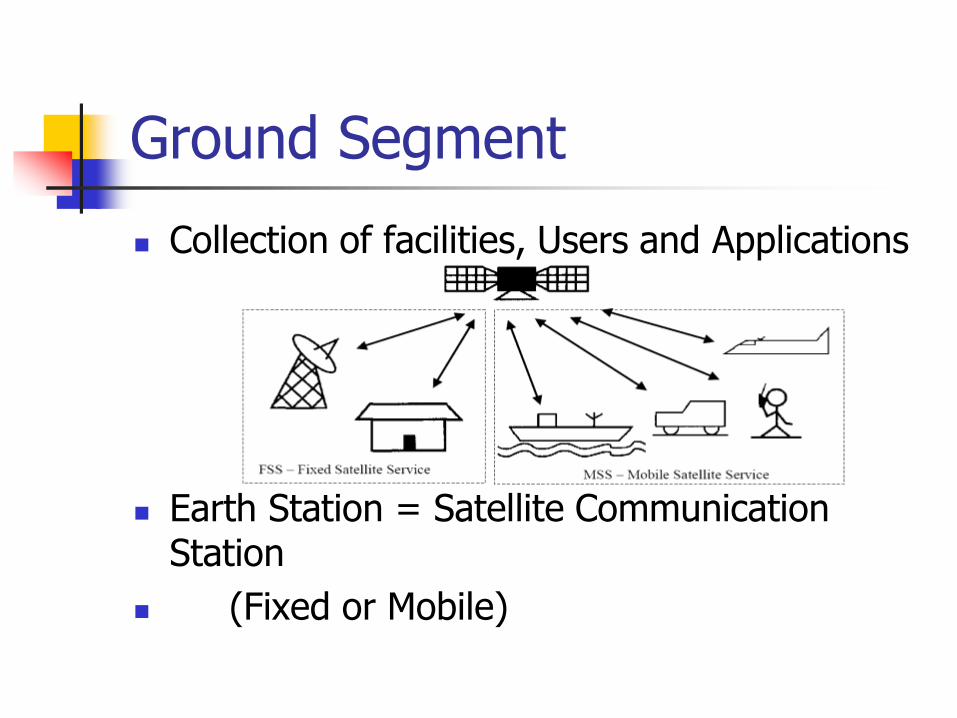
Collection of facilities, Users and Applications
Earth Station = Satellite Communication Station
(Fixed or Mobile)

Satellite Uplink and Downlink
Downlink The link from a satellite down to one or more ground stations or
receivers
Uplink The link from a ground station up to a satellite.
Some companies sell uplink and downlink services to television stations, corporations, and to other telecommunication
carriers.
A company can specialize in providing uplinks, downlinks, or both.

Why Two Frequencies for Uplink and Downlink in Satellite Com
The reason the uplink and downlink frequencies are different in satellites is because otherwise the satellite's transmitter and receiver would interfere with one another. The signals have to operate on different frequencies.
If you could send a signal, then wait, the receiver could be protected from the transmitted signal on the same frequency, but with high speed, continuous transmission, the receiver cannot be turned off while the transmitter is transmitting. (an example of something that transmits and receives on the same frequency is pulsed RADAR, where the transmitter sends out a pulse, and then the echo is picked up by the receiver)

Why Uplink Frequency is Higher than Downlink Frequency
The signals have to cross the atmosphere which presents a great deal of attenuation. The higher the frequency, the more is the signal loss and more power is needed for reliable transmission.
A satellite is a light-weight device which cannot support high-power transmitters on it. So, it transmits at a lower frequency (higher the frequency, higher is the transmitter power to accommodate losses) as compared to the stationary earth station which can afford to use very high-power transmitters. This is compensated by using highly sensitive receiver circuits on the earth station which is in the line-of-sight (LOS) of the satellite.

Uplink/Downlink Mobile/Satellite
A mobile is a portable device which cannot afford high-power transmission as it has a small battery with limited power. The 'free space path loss' comes to play. The higher the transmitting frequency, the higher is the loss. Since a mobile station (cellphone) cannot afford to transmit at high power to compensate for this loss, it must transmit on a lower frequency as a lower frequency presents lesser free space path loss. Therefore, mobile-to-base station (uplink) frequencies are lower than base station-to-mobile(downlink) frequencies.

Satellite Uplink and Downlink

Satellite Communication
When using a satellite for long distance communications, the satellite acts as a repeater.
An earth station transmits the signal up to the satellite (uplink), which in turn retransmits it to the receiving earth station (downlink).
Different frequencies are used for uplink/downlink.

Satellite Transmission Links
Earth stations Communicate by sending signals to the satellite on an uplink
The satellite then repeats those signals on a downlink
The broadcast nature of downlink makes it attractive for services such as the distribution of TV programs

Direct to User Services
One way Service (Broadcasting) Two way Service (Communication)

Satellite Signals
Used to transmit signals and data over long distances
Weather forecasting
Television broadcasting
Internet communication
Global Positioning Systems

Advantages of Satellite Communication
Can reach over large geographical area
Flexible (if transparent transponders)
Easy to install new circuits
Circuit costs independent of distance
Broadcast possibilities
Temporary applications (restoration)
Niche applications
Mobile applications (especially "fill-in")
Terrestrial network "by-pass"
Provision of service to remote or underdeveloped areas
User has control over own network
1-for-N multipoint standby possibilities

Disadvantages of Satellite Communication
Large up front capital costs (space segment and launch)
Terrestrial break even distance expanding (now approx. size of Europe)
Interference and propagation delay
Congestion of frequencies and orbits

When to use Satellites
When the unique features of satellite communications make it attractive
When the costs are lower than terrestrial routing
When it is the only solution
Examples:
Communications to ships and aircraft (especially safety communications)
TV services - contribution links, direct to cable head, direct to home
Data services - private networks
Overload traffic
Delaying terrestrial investments
1 for N diversity
Special events

When to use Terrestrial
PSTN - satellite is becoming increasingly uneconomic for most trunk telephony routes
but, there are still good reasons to use satellites for telephony such as: thin routes, diversity, very long distance traffic and remote locations.
Land mobile/personal communications - in urban areas of developed countries new terrestrial infrastructure is likely to dominate (e.g. GSM, etc.)
but, satellite can provide fill-in as terrestrial networks are implemented, also provide similar services in rural areas and underdeveloped countries

Frequency Bands Allocated to the FSS(Fixed service satellite)
Frequency bands are allocated to different services at World Radio-communication Conferences (WRCs).
Allocations are set out in Article S5 of the ITU Radio Regulations.
It is important to note that (with a few exceptions) bands are generally allocated to more than one radio services.
CONSTRAINTS
Bands have traditionally been divided into “commercial" and "government/military" bands, although this is not reflected in the Radio Regulations and is becoming less clear-cut as "commercial" operators move to utilize "government" bands.

Earth’s atmosphere
Source: All about GPS [www.kowoma.de]

Atmospheric Losses
Different types of atmospheric losses can disturb radio wave transmission in satellite systems:
Atmospheric absorption
Atmospheric attenuation
Traveling ionospheric disturbances

Atmospheric Absorption
Energy absorption by atmospheric gases, which varies with the frequency of the radio waves.
Two absorption peaks are observed (for 90º elevation angle):
22.3 GHz from resonance absorption in water vapour (H2O)
60 GHz from resonance absorption in oxygen (O2)
For other elevation angles:
[AA] = [AA]90 cosec

Atmospheric Attenuation
Rain is the main cause of atmospheric attenuation (hail, ice and snow have little effect on attenuation because of their low water content).
Total attenuation from rain can be determined by:
A = L [dB]
where [dB/km] is called the specific attenuation, and can
be calculated from specific attenuation coefficients in tabular form that can be found in a number of publications
where L [km] is the effective path length of the signal through the rain; note that this differs from the geometric path length due to fluctuations in the rain density.

Traveling Ionospheric Disturbances
Traveling ionospheric disturbances are clouds of electrons in the ionosphere that provoke radio signal fluctuations which can only be determined on a statistical basis.
The disturbances of major concern are:
Scintillation;
Polarisation rotation.
Scintillations are variations in the amplitude, phase, polarisation, or angle of arrival of radio waves, caused by irregularities in the ionosphere which change over time.
The main effect of scintillations is fading of the signal.

What is Polarisation?
Polarisation is the property of electromagnetic waves that describes the direction of the transverse electric field.
Since electromagnetic waves consist of an electric and a magnetic field vibrating at right angles to each other.
it is necessary to adopt a convention to determine the polarisation of the signal.
Conventionally, the magnetic field is ignored and the plane of the electric field is used.

Types of Polarisation Linear Polarisation (horizontal or
vertical):
the two orthogonal components of the electric field are in phase;
The direction of the line in the plane depends on the relative amplitudes of the two components.
Circular Polarisation:
The two components are exactly 90º out of phase and have exactly the same amplitude.
Elliptical Polarisation:
All other cases.Linear Polarisation Circular Polarisation

Satellite Communications
Alternating vertical and horizontal polarisation is widely used on satellite communications
This reduces interference between programs on the same frequency band transmitted from adjacent satellites (One uses vertical, the next horizontal, and so on)
Allows for reduced angular separation between the satellites.

Ways to CategorizeCommunications Satellites
Coverage area
Global, regional, national
Service type
Fixed service satellite (FSS)
Broadcast service satellite (BSS)
Mobile service satellite (MSS)
General usage
Commercial, military, amateur, experimental

Classification of Satellite Orbits
Circular or elliptical orbit Circular with center at earth’s center
Elliptical with one foci at earth’s center
Orbit around earth in different planes Equatorial orbit above earth’s equator
Polar orbit passes over both poles
Other orbits referred to as inclined orbits
Altitude of satellites Geostationary orbit (GEO)
Medium earth orbit (MEO)
Low earth orbit (LEO)

Minimum Elevation Angle
Reasons affecting minimum elevation angle of earth station’s antenna (>0o) Buildings, trees, and other terrestrial
objects block the line of sight
Atmospheric attenuation is greater at low elevation angles
Electrical noise generated by the earth's heat near its surface adversely affects reception

GEO Orbit
Advantages of the the GEO orbit No problem with frequency changes
Tracking of the satellite is simplified
High coverage area
Disadvantages of the GEO orbit Weak signal after traveling over 35,000 km
Polar regions are poorly served
Signal sending delay is substantial

LEO Satellite Characteristics
Circular/slightly elliptical orbit under 2000 km
Orbit period ranges from 1.5 to 2 hours
Diameter of coverage is about 8000 km
Round-trip signal propagation delay less than 20 ms
Maximum satellite visible time up to 20 min
System must cope with large Doppler shifts
Atmospheric drag results in orbital deterioration

LEO Categories
Little LEOs Frequencies below 1 GHz
5MHz of bandwidth
Data rates up to 10 kbps
Aimed at paging, tracking, and low-rate messaging
Big LEOs Frequencies above 1 GHz
Support data rates up to a few megabits per sec
Offer same services as little LEOs in addition to voice and positioning services

MEO Satellite Characteristics
Circular orbit at an altitude in the range of 5000 to 12,000 km
Orbit period of 6 hours
Diameter of coverage is 10,000 to 15,000 km
Round trip signal propagation delay less than 50 ms
Maximum satellite visible time is a few hours

Frequency Bands Available for Satellite Communications

Satellite Link Performance Factors
Distance between earth station antenna and satellite antenna
For downlink, terrestrial distance between earth station antenna and “aim point” of satellite
Displayed as a satellite footprint (Figure 9.6)
Atmospheric attenuation
Affected by oxygen, water, angle of elevation, and higher frequencies

Satellite Network Configurations

Capacity Allocation Strategies
Frequency division multiple access (FDMA)
Time division multiple access (TDMA)
Code division multiple access (CDMA)

Frequency-Division Multiplexing
Alternative uses of channels in point-to-point configuration
1200 voice-frequency (VF) voice channels
One 50-Mbps data stream
16 channels of 1.544 Mbps each
400 channels of 64 kbps each
600 channels of 40 kbps each
One analog video signal
Six to nine digital video signals

Frequency-Division Multiple Access
Factors which limit the number of subchannels provided within a satellite channel via FDMA
Thermal noise
Intermodulation noise
Crosstalk

Forms of FDMA
Fixed-assignment multiple access (FAMA)
The assignment of capacity is distributed in a fixed manner among multiple stations
Demand may fluctuate
Results in the significant underuse of capacity
Demand-assignment multiple access (DAMA)
Capacity assignment is changed as needed to respond optimally to demand changes among the multiple stations

FAMA-FDMA
FAMA – logical links between stations are preassigned
FAMA – multiple stations access the satellite by using different frequency bands
Uses considerable bandwidth

DAMA-FDMA
Single channel per carrier (SCPC) –bandwidth divided into individual VF channels Attractive for remote areas with few user stations
near each site
Suffers from inefficiency of fixed assignment
DAMA – set of subchannels in a channel is treated as a pool of available links For full-duplex between two earth stations, a pair
of subchannels is dynamically assigned on demand
Demand assignment performed in a distributed fashion by earth station using CSC

Reasons for Increasing Use of TDM Techniques
Cost of digital components continues to drop
Advantages of digital components
Use of error correction
Increased efficiency of TDM
Lack of intermodulation noise

FAMA-TDMA Operation
Transmission in the form of repetitive sequence of frames Each frame is divided into a number of time slots
Each slot is dedicated to a particular transmitter
Earth stations take turns using uplink channel Sends data in assigned time slot
Satellite repeats incoming transmissions Broadcast to all stations
Stations must know which slot to use for transmission and which to use for reception

FAMA-TDMA Uplink

FAMA-TDMA Downlink

Summary Requirement of Satellite Communication
Satellite UpLink and DownLink
Types of Satellites
Satellite Foot Print (Coverage Area)
Satellite Transmission Bands
UpLink and DownLink Frequencies
Signal Propagation Delay
Transponder
Effect of Rain on Satellite Communication
Microwave Communication (Why)
Satellite System Elements
Losses
Capacity Allocation Strategies

UNIT IV
Earth station technology

Contents
TC SES Terms of Reference
TC SES Working Groups
Harmonized Standard Working Groups
Specific System Working Groups
External Liaisons
Future Activity

Terms of Reference for Technical Committee for Satellite Earth Stations and Systems (TC SES)
Responsibility
the “Home” in ETSI for Satellite Earth Stations and Systems standardization
The scope includes
All types of satellite communication services and applications (including mobile and broadcasting),
All types of earth stations and earth station equipment, especially the radio frequency interfaces and network and/or user interfaces,
Protocols implemented in earth stations and satellite systems
Responsibility outside ETSI
Primary Committee for co-ordinating the position of ETSI with relevant ITU Study Groups.

Harmonised Standard Working Groups
Working groups dealing with Harmonized standards (R&TTE Directive):
Earth stations on board vessels and trains (MAR ESV)
Harmonisation (HARM)
Working groups dealing with specific systems
Broadband Satellite Multimedia (BSM)
GEO Mobile Radio Interface (GMR)
Satellite Component of IMT 2000 (S-UMTS)
Satellite Digital Radio (SDR)
other Working group
European Commission activity support (ECAS)

WG Earth Stations on board Vessels and Trains MAR ESV (1)
Passenger Communications
Voice Services
Internet Access
Video Broadcast
ATM Services
Global Newspaper Delivery
Cellular Services
Operational Services
Enterprise Data
Lan/Wan Capabilities
Remote Equipment Monitoring
Purchasing/Inventory
Distance Learning/Training
Customs Clearance
Responsibility of the WG is to produce Harmonised Standards for
all type of Earth Stations installed on ship or vessel (ESV), as well
as on trains (EST) operating in FSS frequencies

WG Earth Stations on board Vessels and Trains MAR ESV (2)
The WG has prepared candidate Harmonised Standards for Ku-
band & C-Band ESVs
present status:
• Harmonised Standard EN 302 340,
requirements for protection of FS & FSS in Ku-bandapproved
• Harmonised Standard EN 301 843 part 6 (with TC ERM)
requirements for EMC in maritime environment for ESVs
approved
• Harmonised Standard EN 301 447
requirements for protection of FS & FSS in C-bandpublic enquiry – closes 2 June 2006

WG Earth Stations on board Vessels and Trains MAR ESV (3)
Test systems are in operation in several
European countries – a harmonised EN is necessary.
Work begun in June, 2005, and draft EN should be completed by June, 2006 and submitted to TC SES for approval.
EN 302 448
Satellite Earth Stations on Trains

Working Group HarmonisationHARM (1)
Responsible for:
Maintenance of Harmonised Standards under the R&TTE Directive (99/5 EC).
On-going activities:
EN 301 447 Harmonized EN for satellite Earth Stations on board Vessels (ESVs) operating in the 4/6 GHz frequency bands allocated to the Fixed Satellite Service (FSS) covering essential requirements under article 3.2 of the R&TTE directive
EN 302 448Harmonised EN for tracking Earth Stations on Trains (ESTs) operating in the 14/12 GHz frequency bands covering essential requirements under article 3.2 of the R&TTE directive

Working Group HarmonisationHARM (2)
Other SES Harmonized Standards under the R&TTE Directive (99/5 EC):
EN 301 428 VSAT (Very Small Aperture Terminal) Ku-band satellite earth stations operating in the 11/12/14 GHz frequency bands
EN 301 459 SIT/SUT Ka-band for Satellite Interactive Terminals (SIT) and Satellite User Terminals (SUT) transmitting towards satellites in geo-stationary orbit in the 29.5 to 30.0 GHz frequency bands
EN 301 360 Satellite Interactive Terminals (SIT) and Satellite User Terminals (SUT) transmitting towards geostationary satellites in the 27.5 GHz to 29.5 GHz frequency bands
EN 301 443 Very Small Aperture Terminal (VSAT); transmit-only, transmit-and-receive, receive-only satellite earth stations operating in the 4 GHz and 6 GHz frequency bands
EN 301 430 Satellite News Gathering Transportable Earth Stations (SNG TES) operating in the 11-12/13-14 GHz frequency bands
EN 301 444 Land Mobile Earth Stations (LMES) operating in the 1.5 GHz and 1.6 GHz bands providing voice and/or data communications
EN 301 426 Low data rate Land Mobile satellite Earth Stations (LMES) and Maritime Mobile satellite Earth Stations (MMES) not intended for distress and safety communications operating in the 1.5/1.6 GHz frequency bands

Working Group HarmonisationHARM (3)
Harmonised ENs for Mobile Earth Stations (MES):
EN 301 681 MES for Geostationary mobile satellite systems, including handheld earth stations, for Satellite Personal Communications Networks (S-PCN) in the 1.5/1.6 GHz bands under the Mobile Satellite Service (MSS)
EN 301 721 MES providing Low Bit Rate Data Communications (LBRDC) using Low Earth Orbiting (LEO) satellites operating below 1 GHz
EN 301 441 MES including handheld earth stations, for Satellite Personal Communications Networks (S-PCN) in the 1.6/2.4 GHz bands under the Mobile Satellite Service (MSS)
EN 301 442 MES including handheld earth stations, for Satellite Personal Communications Networks (S-PCN) in the 2.0 GHz bands under the Mobile Satellite Service (MSS)
EN 301 427 Low data rate MES except aeronautical mobile satellite earth stations, operating in the 11/12/14 GHz frequency bands

WG on Broadband Satellite MultimediaBSM (1)
To produce specifications, standards and other ETSI deliverables for broadband satellite multimedia. This includes:
Definition of satellite system architectures supporting broadband services
Service requirements and descriptions for broadband communications systems
Definition of network architectures and interface protocols leading to air interface standards, interworking standards and other user terminal specifications
To liaise with relevant other standardization bodies (e.g. TIA, ITU) on satellite matters

External Bearer Service
SI-SAP and IP Interworking
BSM Bearer Services
TCP/IP services
SI-
SA
P
External
Bearer Service
End
System
End
System
IPInterworking
IPInterworking
BSM Satellite Network
Inte
rwo
rkin
g
Inte
rwo
rkin
g
ST/A ST/G
ST/A
ST/A
ST/G
Payload
PremisesNetwork
PremisesNetwork
PremisesNetwork
CoreNetwork
Satellite
End
System
End
System
End
System
End
System
End
System
End
System
End
System
SI-
SA
P
WG on Broadband Satellite Multimedia
BSM (2)
ST/Access ST/Gateway

BSM Overview
WG BSM has the following focus:
GSO satellites
Fixed satellite terminals
Access Networks
Internet Protocol
Work items organised using the BSM architecture:
Satellite Independent upper layer specifications
IP interworking specifications; dealing with QoS, Addressing, Multicast, Security etc.
Satellite Dependent families of lower layer specifications
Air interfaces and profiles for Transparent Satellite Star (TSS) and Regenerative Satellite Mesh (RSM) systems
Satellite Independent interface (SI-SAP)
Common interface between upper and lower layers
WG on Broadband Satellite Multimedia
BSM (3)

BSM Architecture The BSM architecture divides the air interface into 2 parts
Satellite independent upper layers
Satellite dependent lower layers
Satellite Independent Service Access Point (SI-SAP) defined as the interface between the upper and lower layers An abstract functional interface
Applicable to all satellite networks
The upper layers contain a set of common BSM defined IP interworking functions Define Satellite Independent Adaptation Functions (SIAF)
Common ways of handling Quality of Service (QoS); Addressing; Multicast and Security etc.
The lower layers contain the satellite specific functions The lower layers are closely tied to the payload capability of the satellite and
hence cannot be the same in all cases
The SI-SAP supports multiple air interface families
WG on Broadband Satellite Multimedia
BSM (4)

IP Interworking standards # 1 (TS completed)
SI-SAP specification [TS 102 357; TR 102 353] First release giving functional organisation of SI-SAP
TR provides SI-SAP guidelines
BSM functional architecture [TS 102 292] Generic functional architecture
Defines the SI-SAP and the associated adaptation functions for IP interworking
BSM multicast functional architecture [TS 102 294] Satellite specific functions for multicast services
IGMP adaptation [TS 102 293] Adaptation of IGMP messages
Can be combined with IGMP proxies and snooping
BSM Traffic Classes [TS 102 295] Common Traffic classes for IP interworking
WG on Broadband Satellite Multimedia
BSM (5)

ETSI/SES-BSM Liaisons with other bodies
TIA 34.1
Joint publication of air interface families
Contributions on IP interworking
ITU-R WP 4B
Collaboration on use of BSM architecture
ITU-T SG13 (WP2/13; Q10/13)
Liaison on Y.SatIP series recommendations
IETF
Collaboration with ipdvb WG
SatLabs
Collaboration with SatLabs DVB-RCS working groups
WG on Broadband Satellite Multimedia
BSM (6)

Working Group on Geo Mobile RadioGMR (1)
Geo-Mobile Radio (GMR) is a satellite-based extension of the GSM terrestrial cellular standard
The GMR air interface specifications describe requirements to support a mobile satellite service via geostationary earth orbit satellites
Document structure based on GSM specifications

Working Group on Geo Mobile RadioGMR (2)
The GMR specifications are organized into two releases
Release 1 specifications (Version V1.x.x) Defines the GMR circuit mode services, which are based on the GSM phase 2
circuit mode services.
published jointly in ETSI (TC SES) and in TIA (TR 34.1)
Release 2 specifications (Version V2.x.x) Defines the GMR packet mode services (GMPRS) which are based on the GSM
phase 2+ packet mode services (GPRS)
Release 1 and Release 2 coexist (2 parallel versions) Separate maintenance updates for Release 1 and Release 2

Working Group on Geo Mobile RadioGMR (3)
GSM (Phase 2)
Voice
Data up to 9.6 kbps
SMS, cell broadcast
GSM/GPRS (Phase 2+)
Packet data to 160
kbps
GSM/EDGE (Extended GPRS)
Packet data to 384
kbps
GMR Release 1
- based on GSM Phase 2
Voice
Data up to 9.6 kbps
SMS, cell broadcast
Position-based services
Single hopped TtT calls
GMR Release 2 (GMPRS)
- based on GSM Phase 2+
(GPRS)
Packet data to 144 kbps

Working Group on Geo Mobile RadioGMR (4)
GMR-1 publication history Release 1: GMR-1 V1.1.1 – Published March 2001
2 Maintenance updates:
GMR-1 V1.2.1 – Published March 2002
GMR-1 V1.3.1 – Published February 2005 Release 2: GMPRS-1 V2.1.1 – Published March 2003
1 Enhancement and maintenance update:
GMPRS-1 V2.2.1 – Published March 2005
GMR-2 publication history Release 1: GMR-2 V1.1.1 – Published March 2001

New Activities have been launched
New release of specification of S-UMTS Air Interface
6 new Work Items
Detailed specification of SDMB
6 Work Items
Technical report on OFDM waveform for SDMB
One work Item
Harmonisation of SW CDMA, SAT CDMA and WCDMA Satellite Radio Interface
This WI has been reactivated
Collaboration with ETRI
Several meetings to be held in 2006
Working Group S-UMTS/IMT2000 S-UMTS(1)

Working Group S-UMTS/IMT2000S-UMTS (2)
Current topics Study for Satellite UMTS (S-UMTS) Terminals in the 2.0 GHz bands
under the Mobile Satellite Service (MSS) Based on EN 301 908-1/2 :Electromagnetic compatibility and
Radio spectrum Matters (ERM); Base Stations (BS), Repeaters and User Equipment (UE) for IMT-2000 Third-Generation cellular networks
DEN/SES-00283 Satellite Component of UMTS/IMT-2000; Harmonized standard for Satellite earth Station for UMTS; Part 1: Intermediate Module Repeater (IMR) operating in the 1
980 MHz to 2 010 MHz (earth-to-space) and 2 170 MHz to 2 200 MHz (space-to-earth) frequency bands
Part 2: User Equipment (UE) operating in the 2170 to 2200 MHz (space-to-earth) and 1980 to 2010 MHz (earth-to-space) frequency bands
Proposed schedule TC SES Approval in 2006
Details on activity

Working Group Satellite Digital Radio SDR
SDR: Satellite broadcast to fixed and mobile receivers mainly for audio with or without terrestrial repeater network
Started work in December 2004 Work items:
Technical Report on SDR technologiesApproved, under publication process
Technical Specifications for the physical layer of the radio interface (air interface) of SDR broadcast receiversWork started, completion by 28 September 2006
Technical Specification for the complete radio interface (air interface) of SDR broadcast receiversFuture work
Members participating: Operators, CE manufacturers, satellite manufacturers Cooperation with SSP WG (Satellite Services to Portables) in the DVB forum

Working Group Satellite Emergency CommunicationsSEC
A new working group has been recently created to assess potential new standardization work dealing with satellite usage during emergency situations

European Commission Activity support in standardizationECAS
This work group is dedicated to support ESA standardization work in particular related to the Galileo satellite navigation project

ECAS WG The Galileo Navigation System
Galileo is an initiative of the European Space Agency (ESA) and the European Commission (EC)
Galileo will provide localisation and time information as free services and certified position and time stamping services on subscription basis
These services are candidates for maritime, aeronautical and road/rail/traveller applications
the introduction of Galileo allied with GSM or UMTS will provide the market with combined communication and position determination

ECAS WGGalileo Applications
Transport: Aviation; Rail; Roads; Maritime; Public Transport Telecommunications: Network Timing; Mobile Unit Location Energy, The Environment & Science Civil Engineering: Facilities Location; Positioning Safety & Civil Protection Finance & Insurance Agriculture & Fisheries People with disabilities Leisure

Galileo-GPS co-operation
users will be able to use Galileo and US GPS in a complementary way by receiving signals from both systems with the same receiver
US and EC agreed to adopt a common signal for certain services and to preserve national security capabilities
The Galileo project is expected to be operational around 2010

ETSI Standards for Galileo…
Need for an Open Standard for Galileo identified
Talks with Galileo Joint Undertaking (GJU) have been engaged
Basis for contribution to ICAO, Eurocae for Aeronautical applications
results of working groups responsible for the design of the Galileo system and user equipment are taken into account
Development of an Open Standard through ETSI Expertise and Publications
Approach based on annual Releases, in progression with the definition of the system design

TC-SES liaisons with external bodies
ITU R WP 4B (FSS)
ITU R WP 8D (MSS)
ITU R WP 8F (IMT2000)
ITU T SG 13 (QoS)
Eurocae (Aeronautical)
TIA TR 34.1.1 (BSM)
ITU ICG SAT (Satellite)
ASMS TF (S-UMTS)

CONCLUSION
TC SES is the focal point in Europe for activity covering satellite standardisation
TC SES activities cover all aspects of standardisation of satellite systems
TC SES stands ready to prepare an Open Standard for the Galileo Navigation System and to be involved in standardisation in the field of satellite use during emergency situations

UNIT V
Satellite packet
communications

Principle of Protocol Layering

Protocols supported by VSAT Networks
A summary of the protocols in general use and their support over typical VSAT networks is provided in Table 8.2.
When first introduced in the 1980s, VSATs played heavily on the traditional IBM proprietary protocol, Systems Network Architecture (SNA), which followed the same centralized approach as the VSAT star network.
While still in existence in some legacy environments, it has been replaced with the more open Internet Protocol suite (TCP/IP).
TCP/IP has its shortcomings, which are being addressed by standards bodies and major vendors like Cisco.
Employing TCP/IP in a private network is very straightforward and is well within the means of any organization or individual.

Protocols supported by VSAT Networks
Protocols supported by VSAT Networks
However, the complexity comes when an organization wishes to interconnect with the global Internet and with other organizations.
This is due to the somewhat complex nature of routing protocols like the Border Gateway Protocol (BGP) and a new scheme called Multi Protocol Label Switching (MPLS).
Frame Relay has been popular in WANs for more than a decade, thanks to its ease of interface at the router and availability in (and between) major countries.
It is capable of near-real-time transfer and can support voice services. With access speeds generally available at 2 Mbps or less.
Satellite provision of Frame Relay has been limited to point-to-point circuits as the protocol is not directly supported in VSATs currently on the market.
The best approach would be to use TCP/IP in lieu of Frame Relay when VSAT links are interfaced at the router.

Satellite Point to Point Connectivity
The first satellite networks to be implemented were employed for point-to-point connectivity to complement the cross-country microwave and undersea cable links of the time.
This topology remains an effective means of transferring information with minimum delay between pairs of points.
As illustrated in Figure 8.2, node 1 in a point-to-point service conducts a full-duplex conversation with node 2 (shown with heavy arrows), and node 3 does likewise with node 4 (shown with broken arrows).
For applications such as Fixed Telephony Satellite Services, Point-to-point connectivity between node 1 and node 3 can be changed on demand.
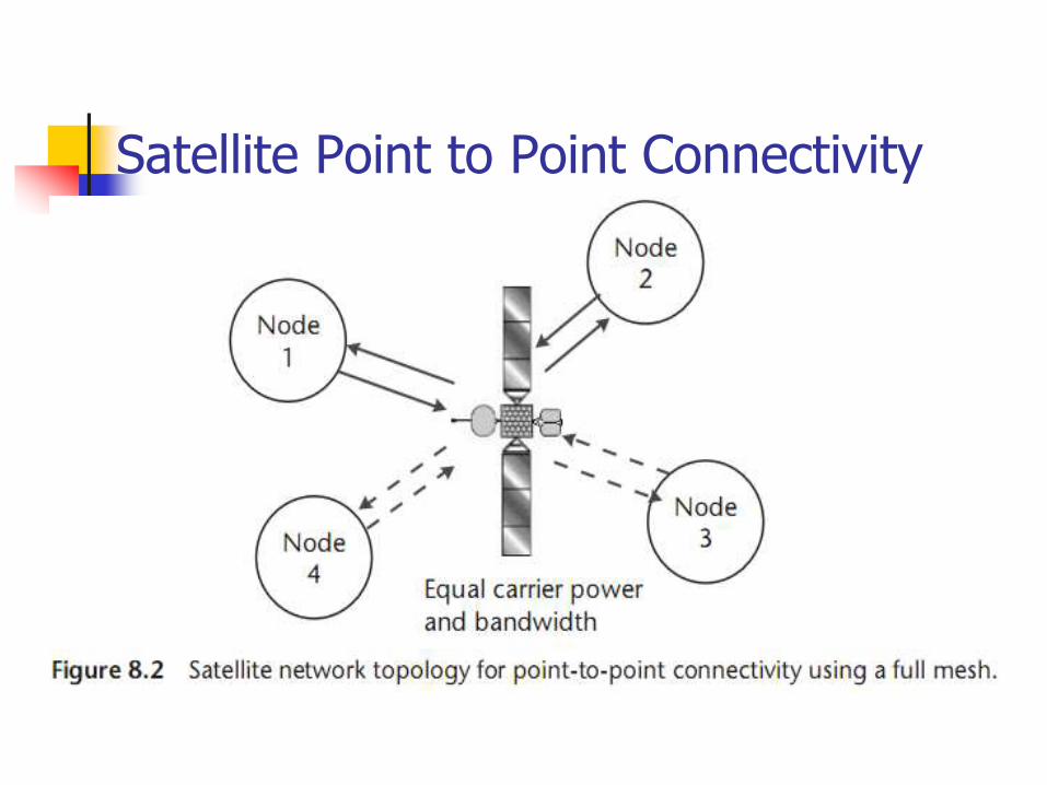
Satellite Point to Point Connectivity

Satellite Point to Multipoint Connectivity
The point-to-multipoint connectivity is illustrated in Figure 8.4.
The thick, shaded arrows represent the digital broadcast “outroute” from the hub to the remote nodes (other acceptable terms for the hub transmitted signal are “outbound,” “forward,” and “downstream”).
It contains all hub-originated data to be delivered to the VSATs throughout the network.
This transmission is received by all remotes within the satellite footprint; however, it would typically contain address information that allows only the desired remotes to select the information destined for them.
The thin lines represent the “inroutes” from the individual remote nodes (likewise, acceptable terms include “inbound,” “return,” and “upstream”).

Satellite Point to Multipoint Connectivity

VSAT Star Networks
Organizations employ VSATs primarily as replacements for terrestrial data networks using private lines in a variety of applications, including retailing, postal and package delivery, automobile sales and service, banking and finance, travel and lodging, and government administration and security.
Perhaps the first major installation was for Wal-Mart, the leading U.S. retailer with stores throughout the United States and other locations around the world.
Today, there are more than 250,000 two-way VSATs installed in the United States and over 600,000 worldwide.
Not included is the consumer VSAT designed to provide Internet access

VSAT Star Networks

VSAT Star Networks VSAT technology should only be used as a supplement to high-
quality digital fiber optic and wireless networks of the world. In fact, the best strategy is often to complement the terrestrial network infrastructure with VSATs so as to achieve an optimum and reliable mix.
For example, a European company needing to connect only five domestic locations to a data center would find that conventional VSATs may not be cost-effective.
Likewise, a large industrial organization that needs high-capacity links between major sites is not a candidate for existing VSATs.
This would clearly be a better application for fiber optic links, if that were feasible, or point-to-point satellite links.


VSAT Star Networks Applications
Many centralized companies build their IT systems around the host computer that is located at the headquarters or outsourced hosting facility.
This is an ideal starting point for VSAT network adoption since it is centralized.
Table 8.4 provides a listing of popular IT applications now provided over enterprise VSAT networks.
Examples include:
• Retail Marketing—Wal-Mart and JD Group
• Automotive—Daimler-Chrysler and Toyota
• US Postal Services
• Retail Banking—Banamex
The architecture of the typical VSAT star network is provided in Figure 8.6


VSAT Star Networks Applications
The architecture of the typical VSAT star network is provided in Figure 8.6 that depicts how the user connects computers, PCs and other terminals, PBX and telephone systems, and video equipment used in private broadcasting.
The hub of the star is shown on the right in the form of a complete Earth station facility with a relatively large antenna (typically 4.7m at Ku-band and 9m at C-band).
The most common implementations of the star network use TDMon the outroute and TDMA as well as a derivative called ALOHA on the inroute.

VSAT Star Networks Architecture

Personal Computer Integration with the VSAT
The PC is the ideal direct user interface with the VSAT in applications where on-line information delivery is required.
Typical telephone networks have a real throughput of about 40 Kbps; lower rates are common in areas where line quality is poor.
This was once adequate for applications such as on-line service connection, dial-up terminal access to e-mail, and fax.
With the growth of the World Wide Web and the increasing demand for the transfer of large files for graphics, database, and engineering applications, the analog telephone network ceases to be adequate.
The marketplace is provided with VSAT networks that have typical inbound throughputs in the range of 128 Kbps to 2Mbps.

Personal Computer Integration with the VSAT
An example of using the point-to-multipoint feature and the PC is shown in Figure 8.9.
The data files or streams are uplinked from a hub Earth station at the right.
A public ISP or content delivery network service would own and operate the hub.
Information is delivered to the hub over backhaul circuits from one or more servers or other information sources (e.g., a stock market ticker).
Subscribers purchase and install a receive-only VSAT, which need only receive the high-speed forward link broadcast from the hub.

Personal Computer Integration with the VSAT

Operation of Multiple Access Protocols in VSATs
The inbound channel is shared by multiple VSATs that transmit their data in bursts.
Two basic multiple access methods are used for this purpose:
• TDMA
• ALOHA

Operation of Multiple Access Protocols -TDMA
An example of a TDMA burst time frame lasting about 45 ms is provided in Figure 9.4.
As applied to the inbound channel, the transmissions from the VSATs are coordinated and highly synchronized so as to prevent overlap and a resulting loss of information.
Each station (numbered 1 through 10) is allotted a fixed interval of time in which to transmit data.
The frame repeats every 45 ms, producing an average delay per inbound channel burst due to multiple access of 45/2 = 22.5ms.
Obviously, the shorter the frame, the less the average delay.

Operation of Multiple Access Protocols - TDMA

Operation of Multiple Access Protocols - ALOHA
Another approach for separating the inbound channel transmissions in time is the ALOHA protocol.
The scheme is simpler in that the transmissions are uncoordinated; however, the complexity occurs because there are occasional overlaps that result in lost communication.
This is overcome by retransmissions from the affected VSATs.
For example, a slotted ALOHA channel with three users is shown in Figure 9.5.
Slotting refers to requiring that the ALOHA packets fall within timed periods, indicated by the vertical lines.
The upper three horizontal lines represent three VSAT uplinks; the bottom timeline depicts the downlink showing how the ALOHA packets appear after passing through the satellite repeater.

Operation of Multiple Access Protocols - ALOHA
Each VSAT remains in an idle state until there is data to be transmitted.
Lets assume that VSAT 1 is the first to need the channel and so transmits the block of data without waiting.
VSAT 2 transmits next, independently of what happens at users 1 and 3.
From the downlink timeline, we see that VSAT 1 and VSAT 2 do not overlap and hence get through in the clear.
The next packets from VSATs 1 and 3 have reached the satellite at approximately the same time and so have produced a collision.
In the event of such a time overlap, the signals jameach other and the information is lost (indicated by the presence of a dark block in the downlink).
Neither packet is received at the hub—a condition that is inferred by these VSATs because of non-acknowledgment by the hub over the outbound channel.

Operation of Multiple Access Protocols - ALOHA
The way that packets are ultimately transferred is through automatic retransmissions, as shown at the ends of the curved arrows in Figure 9.5.
The delay between the original and retransmitted packets is selected randomly by each VSAT to reduce the possibility of a second collision.
The result of this protocol is that the delay is as small as it can possibly be for a packet that does not experience a collision.
For one that does, the delay is lengthy since it includes at least two round-trip delays plus the delays of the random offset as well as from processing within the hub and VSAT.
In an acceptable operating situation, only 1 in 10 ALOHA packets will experience a collision.

Operation of Multiple Access Protocols - ALOHA

Mobile Satellite Services
Historically, GEO satellites have provided most of the MSS capabilities, in terms of land, sea, and air.
The economy and simplicity of a single satellite along with the ability to use fixed antennas on the ground have allowed GEO to become most suited for these applications.
In addition to the global capability of Inmarsat, a number of GEOMSS networks capable of serving handheld satellite telephones are in service.
The major benefit of the lower orbits is reduced time delay for voice services.
This factor is very important in terrestrial telephone networks, particularly with high-quality transmission as provided through fiber optic technology.
Table 11.3 provides a summary of key attributes of LEO, MEO and GEO Satellites.

Mobile Satellite Services

Mobile Satellite Services

Mobile Satellite Services
Figure 11.9: A selection of user terminal equipment for use with Mobile Satellite Services

Mobile Satellite Services