sans10160 loadings
DESCRIPTION
SABS 0160-1989South African StandardThe General Procedures and Loadings To Be Adopted in the Design of BuildingsTRANSCRIPT
ICS 91.010.30; 91.080.01 ISBN 0-626-09815-7 SABS 01 60-1 989
(As amended 1990, 1991 and 1993)
SOUTH AFRICAN STANDARD
Code of practice for
The general procedures and loadings to be adopted in the design of buildings
Reprint 1994 First Revision Published by THE COUNCIL OF THE SOUTH AFRICAN BUREAU OF STANDARDS Gr18

SABS 01 60-1 989
Amdt No. Date Text affected
I I
I I

ICS 91.010.30; 91.080.01 SABS 01 60-1 989 (As amended 1990,1991 and 1993)
SOUTH AFRICAN BUREAU OF STANDARDS
CODE OF PRACTICE
for
THE GENERAL PROCEDURES AND LOADINGS TO BE ADOPTED IN THE DESIGN OF BUILDINGS
Obtainable from the
South African Bureau of Standards Private Bag X191 Pretoria Republic of South Africa 0001
Telephone : (012) 428-791 1 Fax (012) 344-1568 E-mail : [email protected] Website : http:llwww.sabs.co.za
COPYRIGHT RESERVED
Printed in the Republic of South Africa by the South African Bureau of Standards
SABS 01 60-1 989 (As amended 1991 and 1993)
2
NOTICE
This code of practice was approved by the Council of the South African Bureau of Standards on 7 November 1989.
In terms of the regulations promulgated under the Standards Act, 1982 (Act 30 of 1982), it is a punishable offence for any person to falsely claim compliance with the provisions of a code of practice published by the South African Bureau of Standards.
Authorities who wish to incorporate any part of this code of practice into any legislation in the manner intended by section 33 of the Act should consult the South African Bureau of Standards regarding the implications.
This code will be revised when necessary in order to keep abreast of progress. Comment will be welcomed and will be considered when the code is revised.
First Revision November 1989 Incorporating Amendment No. 1: 15 May 1990 Reprint incorporating Amendment No. 2: 15 November 1991
No. 3: 18 October 1993 This code of practice supersedes SABS 0160-1980
ISBN 0-626-0981 5-7
3 SABS 01 60-1 989 (As amended 1990 and 1993)
CONTENTS
COMMITTEE
SECTION 1 .
SECTION 2 .
SECTION 3
3.1
3.1 . 1 3.1.2 3.1.3 3.1.4 3.1.5 3.1.6
SECTION 4 .
4.1 4.2 4.3 4.4
4.4.1 4.4.2
4.5
4.5.1 4.5.2
SECTION 5 .
5.1 5.2
5.2.1 5.2.2
5.3 5.4
5.4.1
5.4.2
5.4.3 5.4.4 5.4.5
5.5
5.5.1 5.5.2 5.5.3
. . . . . . . . . . . . . . . . . . . . . . . . . . . . . . . . . . . . . . . . . . . . . . . . . . . . . . . . 6
SCOPE . . . . . . . . . . . . . . . . . . . . . . . . . . . . . . . . . . . . . . . . . . . . . . . . . . . . 7
DEFINITIONS . . . . . . . . . . . . . . . . . . . . . . . . . . . . . . . . . . . . . . . . . . . . . . . 7
GENERAL DESIGN CONSIDERATIONS . . . . . . . . . . . . . . . . . . . . . . . . . . 10
Design Requirements . . . . . . . . . . . . . . . . . . . . . . . . . . . . . . . . . . . . . . . . . 10
General . . . . . . . . . . . . . . . . . . . . . . . . . . . . . . . . . . . . . . . . . . . . . . . . . . . . 10 Design procedure . . . . . . . . . . . . . . . . . . . . . . . . . . . . . . . . . . . . . . . . . . . . 10
Vibration . . . . . . . . . . . . . . . . . . . . . . . . . . . . . . . . . . . . . . . . . . . . . . . . . . . . 14 Stability . . . . . . . . . . . . . . . . . . . . . . . . . . . . . . . . . . . . . . . . . . . . . . . . . . . . 15 Integrity . . . . . . . . . . . . . . . . . . . . . . . . . . . . . . . . . . . . . . . . . . . . . . . . . . . . 15
GENERAL GUIDANCE ON LIMIT-STATES DESIGN LOADS . . . . . . . . . . 17
Deformations under service loads . . . . . . . . . . . . . . . . . . . . . . . . . . . . . . . 11
General . . . . . . . . . . . . . . . . . . . . . . . . . . . . . . . . . . . . . . . . . . . . . . . . . . . . 17 Limit-states Criterion of Failure . . . . . . . . . . . . . . . . . . . . . . . . . . . . . . . . . . 17 Limit-states Approach . . . . . . . . . . . . . . . . . . . . . . . . . . . . . . . . . . . . . . . . . 18 Uniform Load Factors and Load Combinations . . . . . . . . . . . . . . . . . . . . . 18
General . . . . . . . . . . . . . . . . . . . . . . . . . . . . . . . . . . . . . . . . . . . . . . . . . . . 18 Limit-states design loads . . . . . . . . . . . . . . . . . . . . . . . . . . . . . . . . . . . . . . 19
Design Codes for Individual Materials . . . . . . . . . . . . . . . . . . . . . . . . . . . . 23
General . . . . . . . . . . . . . . . . . . . . . . . . . . . . . . . . . . . . . . . . . . . . . . . . . . . 23 Assessment of partial material factors for material codes . . . . . . . . . . . . . 23
LOADS . . . . . . . . . . . . . . . . . . . . . . . . . . . . . . . . . . . . . . . . . . . . . . . . . . . . 24
General . . . . . . . . . . . . . . . . . . . . . . . . . . . . . . . . . . . . . . . . . . . . . . . . . . . 24 Load Factors and Load Combinations . . . . . . . . . . . . . . . . . . . . . . . . . . . . 24
Limit-states design methods . . . . . . . . . . . . . . . . . . . . . . . . . . . . . . . . . . . . 24 Working stress design methods . . . . . . . . . . . . . . . . . . . . . . . . . . . . . . . . . 25
Amdt 3. . . . . . . . . . . . . . . . . . . . . . . . . . . . . . . . . . . . NominalPermanentLoadsG, 25 Oct . 1993 NominallmposedLoadsQ, . . . . . . . . . . . . . . . . . . . . . . . . . . . . . . . . . . . . 25
Nominal imposed floor loads in buildings containing occupancies
Nominal imposed floor loads in buildings containing storage and
Nominal imposed roof loads . . . . . . . . . . . . . . . . . . . . . . . . . . . . . . . . . . . . 31
Wind Loads W, . . . . . . . . . . . . . . . . . . . . . . . . . . . . . . . . . . . . . . . . . . . . . 34
Determination of nominal wind loads . . . . . . . . . . . . . . . . . . . . . . . . . . . . . 34 Nominalwindspeed V, . . . . . . . . . . . . . . . . . . . . . . . . . . . . . . . . . . . . . . . 36 Nominal wind pressures and forces . . . . . . . . . . . . . . . . . . . . . . . . . . . . . . 41
other than industrial and storage occupancies . . . . . . . . . . . . . . . . . . . . . 25
. . . . . . . . . . . . . . . . . . . . . . . . . . . . . . . . . . . . . . . . industrialoccupancies 29 Amdt 3. Load reduction . . . . . . . . . . . . . . . . . . . . . . . . . . . . . . . . . . . . . . . . . . . . . . 30 993
Forces on walls, balustrades and glazing . . . . . . . . . . . . . . . . . . . . . . . . . . 32

SABS 01 60-1 989
Blank
4
5
CONTENTS (continued)
SABS 01 60-1 989 (As amended 1990)
5.5.4 Pressure and force coefficients . . . . . . . . . . . . . . . . . . . . . . . . . . . . . . . . . . 45
5.5.6 Simplified wind load design . . . . . . . . . . . . . . . . . . . . . . . . . . . . . . . . . . . . . 66
5.6.1 Seismic hazard zones . . . . . . . . . . . . . . . . . . . . . . . . . . . . . . . . . . . . . . . . . 67
5.6.3 Planning considerations for low-rise housing in Zone II . . . . . . . . . . . . . . . 71 5.6.4 Design load effect and load combinations . . . . . . . . . . . . . . . . . . . . . . . . . 72 5.6.5 Seismic base shear . . . . . . . . . . . . . . . . . . . . . . . . . . . . . . . . . . . . . . . . . . . 72 5.6.6 Distribution of seismic forces . . . . . . . . . . . . . . . . . . . . . . . . . . . . . . . . . . . 76 5.6.7 Structural component load effects . . . . . . . . . . . . . . . . . . . . . . . . . . . . . . . . 77
5.7 Loads due to Overhead Travelling Cranes . . . . . . . . . . . . . . . . . . . . . . . . . 78
5.5.5 Dynamiceffects . . . . . . . . . . . . . . . . . . . . . . . . . . . . . . . . . . . . . . . . . . . . . . 64
5.6 EarthquakeLoads . . . . . . . . . . . . . . . . . . . . . . . . . . . . . . . . . . . . . . . . . . . . 67
5.6.2 Design considerations for multistorey buildings in Zone I and Zone II . . . . 70
5.7.1 5.7.2 5.7.3 5.7.4 5.7.5 5.7.6 5.7.7 5.7.8 5.7.9
General . . . . . . . . . . . . . . . . . . . . . . . . . . . . . . . . . . . . . . . . . . . . . . . . . . . . Classification of travelling cranes . . . . . . . . . . . . . . . . . . . . . . . . . . . . . . . . Vertical wheel loads . . . . . . . . . . . . . . . . . . . . . . . . . . . . . . . . . . . . . . . . . . . Horizontal transverse forces. . . . . . . . . . . . . . . . . . . . . . . . . . . . . . . . . . . . . Horizontal longitudinal force . . . . . . . . . . . . . . . . . . . . . . . . . . . . . . . . . . . . Forcesonendstops . . . . . . . . . . . . . . . . . . . . . . . . . . . . . . . . . . . . . . . . . . Position of crane and crab More than one crane in a building Combination of crane lateral forces and wind load
. . . . . . . . . . . . . . . . . . . . . . . . . . . . . . . . . . . . . . . . . . . . . . . . . . . . . . . . . . . . . . . . . . . . . .
. . . . . . . . . . . . . . . . . . .
78 78 79 80 82 82 82 82 82
5.8 Otherloads . . . . . . . . . . . . . . . . . . . . . . . . . . . . . . . . . . . . . . . . . . . . . . . . . 82
5.8.1 Provision for impact and vibration . . . . . . . . . . . . . . . . . . . . . . . . . . . . . . . . 82 5.8.2 Lifting and handling equipment . . . . . . . . . . . . . . . . . . . . . . . . . . . . . . . . . . 83 5.8.3 Lateral and uplift forces . . . . . . . . . . . . . . . . . . . . . . . . . . . . . . . . . . . . . . . . 83 5.8.4 Inertia sway forces . . . . . . . . . . . . . . . . . . . . . . . . . . . . . . . . . . . . . . . . . . . 83 5.8.5 Ceilings, skylights and similar structures . . . . . . . . . . . . . . . . . . . . . . . . . . 83
SECTION 6 . IN-SITU LOAD TESTING OF BUILDINGS AND BUILDING ELEMENTS . . . . . . . . . . . . . . . . . . . . . . . . . . . . . . . . . . . . . . . . . . . . . . . 83
6.1 General . . . . . . . . . . . . . . . . . . . . . . . . . . . . . . . . . . . . . . . . . . . . . . . . . . . 83
6.1 . 1 Types of full scale load tests . . . . . . . . . . . . . . . . . . . . . . . . . . . . . . . . . . . . 83 6.1.2 Planning . . . . . . . . . . . . . . . . . . . . . . . . . . . . . . . . . . . . . . . . . . . . . . . . . . . 84
6.2 Testing Authority . . . . . . . . . . . . . . . . . . . . . . . . . . . . . . . . . . . . . . . . . . . . 84
6.3.1 Planning . . . . . . . . . . . . . . . . . . . . . . . . . . . . . . . . . . . . . . . . . . . . . . . . . . . 84 6.3.2 Conducting of tests . . . . . . . . . . . . . . . . . . . . . . . . . . . . . . . . . . . . . . . . . . 85 6.3.3 Test precautions . . . . . . . . . . . . . . . . . . . . . . . . . . . . . . . . . . . . . . . . . . . . 85
APPENDIX A . APPLICABLE PUBLICATIONS . . . . . . . . . . . . . . . . . . . . . . . . . . . . . . . . . . 88
APPENDIX B . NOMINAL UNIT MASSES CIF MATERIALS . . . . . . . . . . . . . . . . . . . . . . . . 90
APPENDIX C . NOMINAL IMPOSED LOADS . . . . . . . . . . . . . . . . . . . . . . . . . . . . . . . . . . . 95
APPENDIX D . WIND FORCES . . . . . . . . . . . . . . . . . . . . . . . . . . . . . . . . . . . . . . . . . . . . . 97
APPENDIX E . DEFORMATION OF BUILDINGS . . . . . . . . . . . . . . . . . . . . . . . . . . . . . . . . 105
APPENDIX F . RAINFALL INTENSITY . . . . . . . . . . . . . . . . . . . . . . . . . . . . . . . . . . . . . . . 119
6.3 Testprocedures . . . . . . . . . . . . . . . . . . . . . . . . . . . . . . . . . . . . . . . . . . . . 84

SABS 01 60-1 989 6
COMMITTEE
South African Bureau of Standards . . . . . . . . . . . . . . . . . . . . . . . . . . . . . . . . RH Watkins (Chairman) I Jablonski (Standards Writer) A van Wyk (Committee Clerk)
Bruinette, Kruger, Stoffberg Incorporated . . . . . . . . . . . . . . . . . . . . . . . . . . . HJ Maoc
Concrete Masonry Association . . . . . . . . . . . . . . . . . . . . . . . . . . . . . . . . . . . . JW Lane
CSlR Division of Building Technology . . . . . . . . . . . . . . . . . . . . . . . . . . . . . . . . . . JAP Laurie
RV Milford
Division of Processing and Chemical Manufacturing Technology . . . . . . . . MR Newham
South African Transport Services . . . . . . . . . . . . . . . . . . . . . . . . . . . . . . . . . . J Geldenhuys
Steel and Engineering Industries' Federation of South Africa . . . . . . . . . . . . FH Pienaar
The South African Association of Consulting Engineers . . . . . . . . . . . . . . . . DJW Wium
University of Pretoria . . . . . . . . . . . . . . . . . . . . . . . . . . . . . . . . . . . . . . . . . . . . BWJ van Rensburg
University of the Witwatersrand . . . . . . . . . . . . . . . . . . . . . . . . . . . . . . . . . . . AR Kemp A Goldstein
7 SABS 01 60-1 989
SOUTH AFRICAN BUREAU OF STANDARDS
CODE OF PRACTICE
for
1.
1 .I
1.2
1.3
2.
2.1
THE GENERAL PROCEDURES AND LOADINGS TO BE ADOPTED IN THE DESIGN OF BUILDINGS
SCOPE
This code of practice details the general structural design procedures and the minimum design loads to be adopted in the design of buildings or their structural members.
This code of practice does not cover the following:
a) Detailed design appropriate to particular construction materials or methods; b) loads on bridges; c) loads on earth-retaining structures and on structures subject to internal pressure from the contents (e.g. bunkers, silos, water tanks, etc.); and d) dynamic loadings due to plant and machinery (other than loadings covered in 5.4.2.3, 5.7, 5.8.1 and 5.8.2).
Loads incidental to construction c:annot, because of the wide variety and nature of the combinations, be specified. It is necessary, however, that the designer give conside- ration to the effects of such loads on a partly completed structure. (See also 5.1.2(b).)
NOTE a) The standards referred to in the code are listed in Appendix A-1 , and references that may be consulted for additional information are listed in Appendix A-2. b) Nominal unit masses of materials that may be used in the calculation of loadings are given in Appendix B. c) The assessment of floor loads in factories and warehouses is covered in Appendix C. d) Further information on wind forces is given in Appendix D. e) Guidance on acceptable limits for deformations of various types of buildings is given in Appendix E. f) Guidance on the design of rainwater disposal from roofs is given in Appendix F.
DEFINITIONS
NOTE: Where it is desired to use t e r m in addition to the terms listed below, these terms should be selected from IS0 8930.
For the purposes of this code of practice the following definitions shall apply:
- Act. The National Building Regulations and Building Standards Act, 1977 (Act 103 of
Action. Any cause (load or imposed deformation) leading to internal forces in, or deformation of, the members of a structure, or the structure as a whole. It may be a) a set of concentrated or distrihuted forces acting on the structure (direct action), or b) imposed or constrained deforrnations within the structure (indirect action). Symbols such as a, a, E, etc., must be chosen to designate each particular indirect action. NOTE: The term "load" may be used with essentially the same meaning as "action". Combination of actions. A set of values for the actions occurring in a structure, that is used for the verification of the structural reliability of a structure for a limit state under the simultaneous influence of differerit actions. Free action. Action which may have any distribution in space over the structure, within certain limits, e.g. action of vehicles on a bridge. Permanent action. Action which is likely to act throughout a given design situation
and for which the variation in magnitude with time is negligible in relation to the mean value, or for which the variation is always in the same direction until the action attains a certain limit value, e.g. self-weight, prestressing force.
1977).
SABS 01 60-1 989 8
Sustained action/Transient action. Terms used for a qualitative classification of actions, e.g. in a floor loading, the weight of the furniture represents the "sustained" action, and the weight of persons represents the "transient" action. Building. As defined in the Act. Code of practice. As defined in the Act. Deflection. Movement of a defined point in a defined direction.
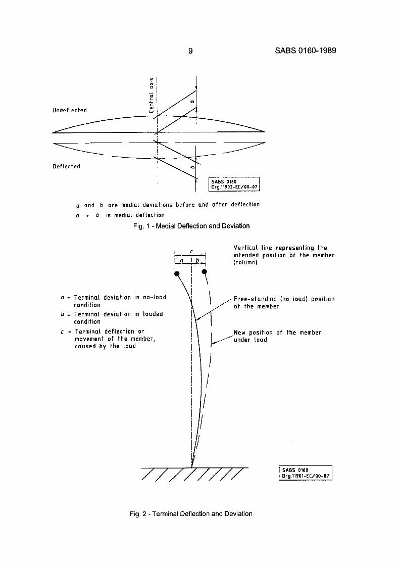
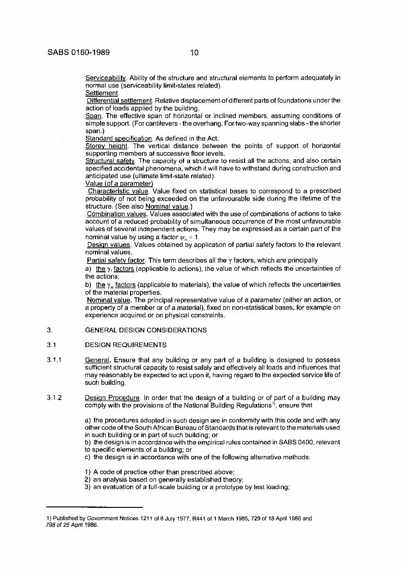
Medial deflection (Fig. 1). Deflection of the middle of a member relative and normal to the line joining its ends.
Terminal deflection (Fig. 2). Deflection of the end of a member relative and normal to the line through the opposite end parallel to its undeflected position. Desiqner. In relation to the erection of a building or of part of a building, a competent person appointed by the owner to be responsible for the design of such building or part. Deviation. The distance of a defined point from a defined datum. Medial deviation (Fig. 1). Deviation of the middle of a member from the straight line or
plane joining its ends. Terminal deviation (Fig. 2). Deviation of the end of a member from the straight line or plane, horizontal or vertical (as relevant) through the opposite end. Durabilitv. Ability of the structure and its members to maintain adequate performance in time. Dwellincl house. A building, together with any outbuildings appurtenant thereto, situated upon its own site and designed for occupation as a separate dwelling for one or more persons forming a household. Dwellins unit. A dwelling other than a dwelling house comprising one or more rooms which have living, sleeping, eating, cooking and sanitary facilities for one or more persons forming a household. Ground movement. Disturbance of foundations by influences not dependent on the loads applied by the building. Limit states. States beyond which the structure no longer satisfies the design (performance) requirements. Serviceabilitv limit states. Limit states related to normal use (often related to function). Ultimate limit state. Limit state corresponding to the maximum load-carrying capacity of a structure or of a part of the structure. Load (see also Action) Desian load. Design value of load. Imposed load (The term Preferred to "live load"). Load due to intended occupancy
(includes loads due to movable partitions and loads due to cranes), snow, ice and rain, earth and hydrostatic pressures, and horizontal components of static and inertia forces. Nominal load. Nominal value of load. Point-in-time load. The most-likely load which is on the structure at any instant in time
(not the lifetime maximum value). Self-weiqht (The term preferred to "dead load"). Load consists of the weight of all the members of the structure itself, plus the weight of all finishes, including permanent partitions, which are to be supported permanently by any member of the structure. Load arranqement. Arrangement of loads introduced into a calculation to allow for the variation in space of a free action, e.g. arrangement of traffic loads on a bridge. Load case. A load case is determined by fixing the arrangement of each of the free actions. Local authoritv. As defined in the Act. National Buildinq Reaulations. As defined in the Act. OccuDancv. The use or purpose to which a building or site is normally put or intended to be put. (See the National Building Regulations for clarification of the various types of occupancies.) Owner. As defined in the Act. Partition. An internal vertical structure that is employed solely for the purpose of subdividing any storey of a building into sections, and that supports no load other than its own weight.
9 SABS 0 1 60- 1 989
Undef lected
A
Def lected
SABS 0160 i Org.11902-EC/00-07
a and b are medial deviat ions be fo re and a f t e r def lect ion a + b is m e d i a l def lect ion
Fig. 1 - Medial Deflection and Deviation
V e r t i c a l l i ne r e p r e s e n t i n g t h e i n tended pos i t i on o f t h e member (column)
a = Te rm ina l dev ia t i on in no - load
b = Te rm ina l dev ia t i on in loaded
c = Terminal d e f l e c t i o n o r
\ condi t ion
condi t ion
movement o f t h e member, caused b y the l o a d
i Free-s tand ing (no load ) pos i t i on '/ o f the member
1 New pos i t i on o f the member under l o a d
I
Fig. 2 - Terminal Deflection and Deviation
SABS 01 60-1 989 10
3.
3.1
3.1.1
3.1.2
Serviceability. Ability of the structure and structural elements to perform adequately in normal use (serviceability limit-states related). Settlement Differential settlement. Relative displacement of different parts of foundations under the action of loads applied by the building. m. The effective span of horizontal or inclined members, assuming conditions of simple support. (For cantilevers - the overhang. For two-way spanning slabs - the shorter span.) Standard specification. As defined in the Act. Storev heiaht. The vertical distance between the points of support of horizontal supporting members at successive floor levels. Structural safety. The capacity of a structure to resist all the actions, and also certain specified accidental phenomena, which it will have to withstand during construction and anticipated use (ultimate limit-state related). Value (of a Darameter) Characteristic value. Value fixed on statistical bases to correspond to a prescribed
probability of not being exceeded on the unfavourable side during the lifetime of the structure. (See also Nominal value.) Combination values. Values associated with the use of combinations of actions to take account of a reduced probability of simultaneous occurrence of the most unfavourable values of several independent actions. They may be expressed as a certain part of the nominal value by using a factor y,, I 1. Desian values. Values obtained by application of partial safety factors to the relevant
nominal values. Partial safetv factor. This term describes all the y factors, which are principally
a) ?,factors (applicable to actions), the value of which reflects the uncertainties of the actions; b) the ym factors (applicable to materials), the value of which reflects the uncertainties of the material properties. Nominal value. The principal representative value of a parameter (either an action, or
a property of a member or of a material), fixed on non-statistical bases, for example on experience acquired or on physical constraints.
G EN ERAL DES I G N CONS I DERATIO N S
DESIGN REQUIREMENTS
General. Ensure that any building or any part of a building is designed to possess sufficient structural capacity to resist safely and effectively all loads and influences that may reasonably be expected to act upon it, having regard to the expected service life of such building.
Desian Procedure. In order that the design of a building or of part of a building may comply with the provisions of the National Building Regulations’), ensure that
a) the procedures adopted in such design are in conformity with this code and with any other code of the South African Bureau of Standards that is relevant to the materials used in such building or in part of such building; or b) the design is in accordance with the empirical rules contained in SABS 0400, relevant to specific elements of a building; or c) the design is in accordance with one of the following alternative methods:
1) A code of practice other than prescribed above; 2) an analysis based on generally established theory; 3) an evaluation of a full-scale building or a prototype by test loading;
1) Published by Government Notices 1211 of 6 July 1977, R441 of 1 March 1985, 729 of 18 April 1986 and 798 of 25 April 1986.
11 SABS 01 60-1 989
3.1.3
4) studies of model analogues; or 5) an authoritative document covering in detail the design of a building or a structural member for a specific purpose or a specific material or both, provided that where a material is used for which there is no SABS specification, the design is in accordance with a safe method applicable to such material.
In terms of the National Building Regulations, alternatives (a) and (b) above are deemed to satisfy the regulations and therefore must in all cases be accepted by the local authority. A design based on one of the methods given in (c) above may have to be justified by the designer to prove that it will ensure the level of safety and performance implicit in the regulations. The deemed-to-satisfy requirements for the use of specific materials employed in the construction of a building or of part of a building are given in
SABS 01 00 for structural concrete SABS 01 37 for glazing SABS 0161 for foundations SABS 0162 for structural steel SABS 0163 for structural timber SABS 0164 for structural masonry
The empirical rules contained in SABS 0400 relate to
Foundations (see Part H) Floors (see Part J) Walls (see Part K) Roofs (see Part L) Glazing (see Part N)
Deformations under Service Loads. So design structural members that their deforma- tions under expected service loads will be acceptable with regard to
a) the intended use of the building or member; b) possible damage to non-struct.ural members and materials; and c) possible damage to the building itself, taking account, where significant, of the additional effects of loads acting on the deformed building or member; and d) possible damage to the adjacent buildings.
NOTE: Table 1 is a summary of suggested deformation limits and should be read in conjunction with Appendix E.
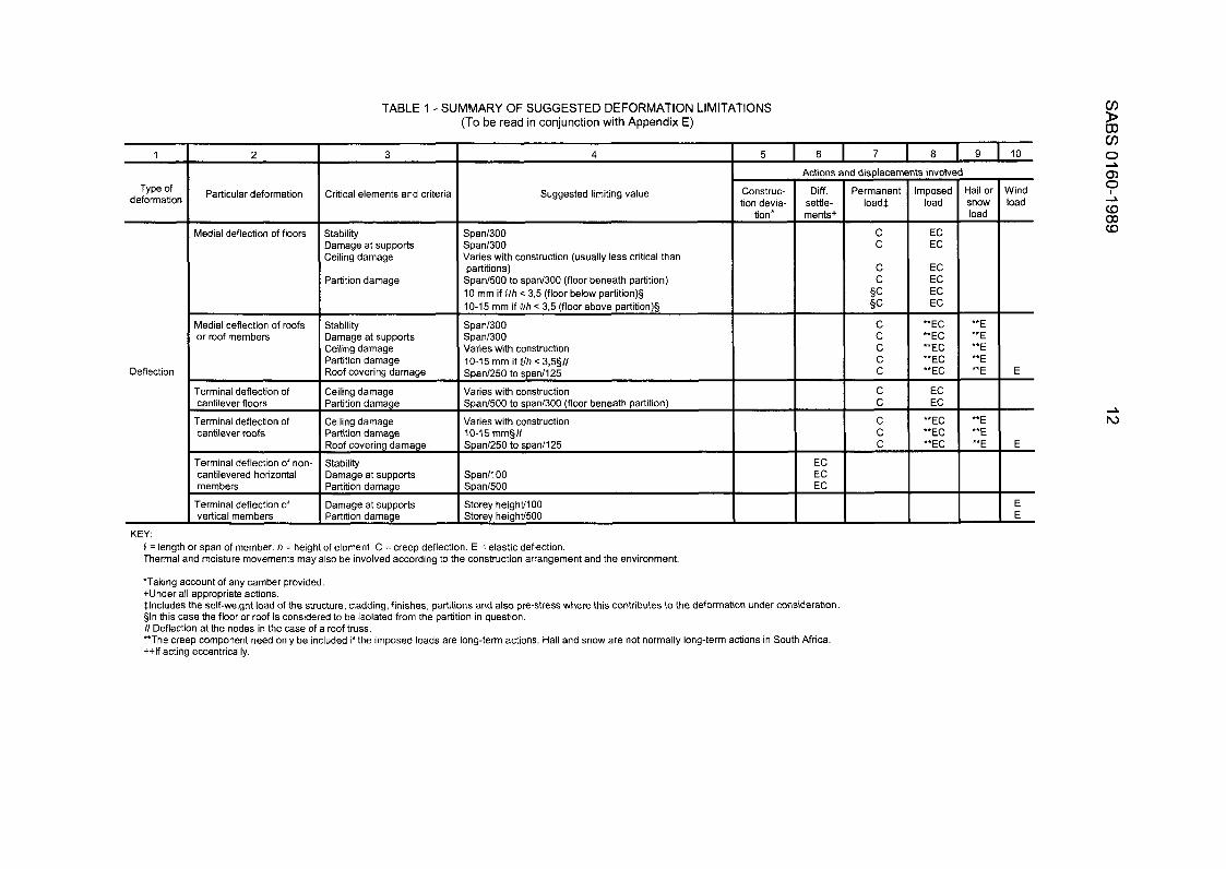
TABLE 1 - SUMMARY OF SUGGESTED DEFORMATION LIMITATIONS (To be read in conjunction with Appendix E)
1 ~~
Type of deformation
Deflection
Particular deformation Critical elements and criteri: I Medial deflection of floors
Medial deflection of roofs or roof members
Terminal deflection of cantilever floors
Terminal deflection of cantilever roofs
Terminal deflection of non- cantilevered horizontal members
Terminal deflection of vertical members
Stability Damage at supports Ceiling damage
Partition damage
Stability Damage at supports Ceiling damage Partition damage Roof covering damage
Ceiling damage Partition damage
Ceiling damage Partition damage
Damage at supports
Damage at supports
4
Suggested limiting value
Span1300 Span1300 Varies with construction (usually less critical than partitions)
Span1500 to span1300 (floor beneath partition) 10 mm if Clh < 3,5 (floor below partition)§ 10-15 mm if Qlh < 3.5 (floor above partition)§
Span1300 Span1300 Varies with construction 10-15 mm if Qlh < 3,5511 Span1250 to span1125
Varies with construction Span1500 to span1300 (floor beneath partition)
Varies with construction 10-1 5 mm§// Span1250 to span1125
Span1100 Span1500
Storey height1100 Storey height1500
5 6 7 a 9 10
Construc- tion devia-
tion*
Actions
Diff. settle- ments+ -
-
-
EC EC EC - -
KEY: Q = length or span of member. h = height of element. C = creep deflection. E = elastic deflection. Thermal and moisture movements may also be involved according to the construction arrangement and the environment.
'Taking account of any camber provided. +Under all appropriate actions. $Includes the self-weight load of the structure, cladding, finishes, partitions and also pre-stress where this contributes to the deformation under consideration §In this case the floor or roof is considered to be isolated from the partition in question. /I Deflection at the nodes in the case of a roof truss. **The creep component need only be included if the imposed loads are long-term actions. Hail and snow are not normally long-term actions in South Africa. ++If acting eccentrically.
I displacements involvc
load$
C I E
C I **EC
C *'EC
1
- iail or snow load -
** E **E "E **E **E
- Nind load -
E
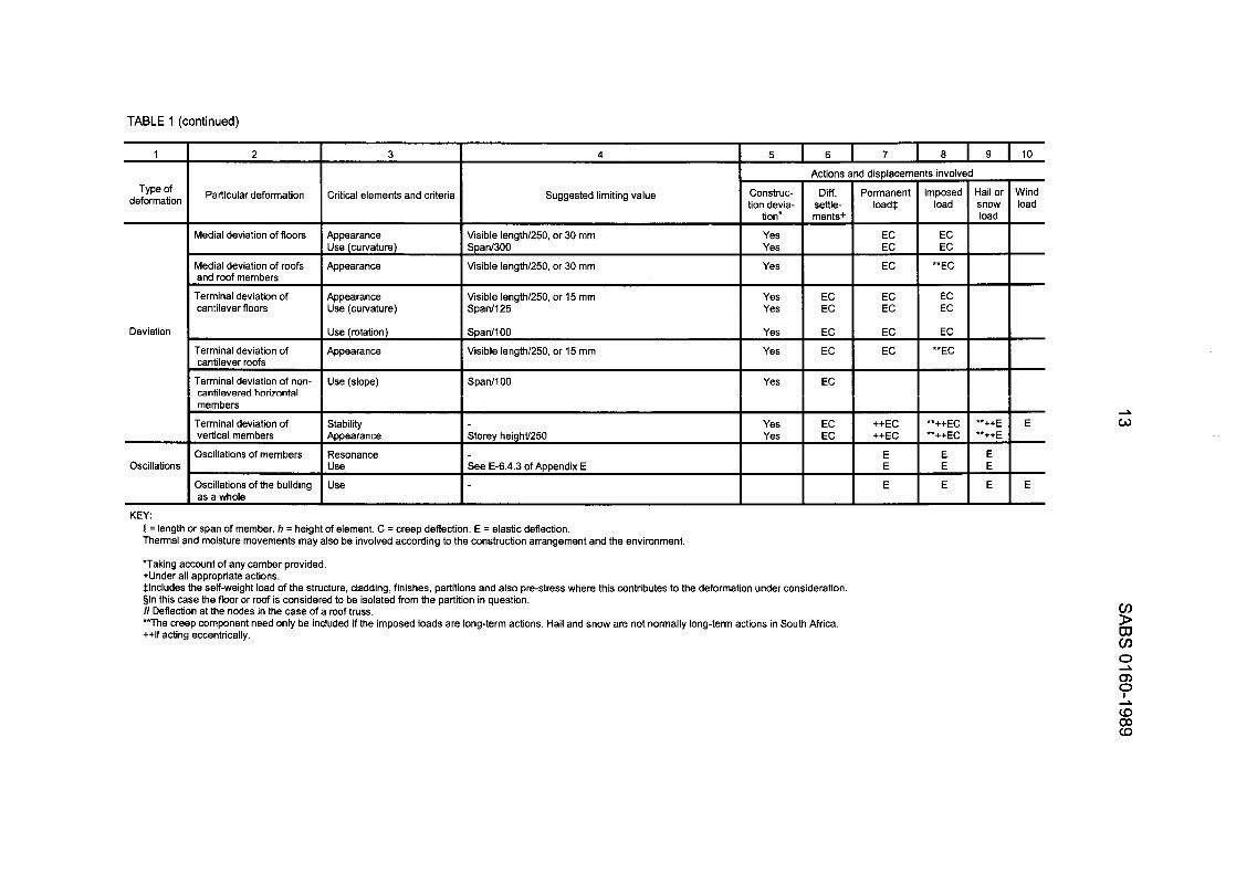
TABLE 1 (continued)
Medial deviation of floors
Medial deviation of roofs and roof members
Terminal deviation of cantilever floors
Terminal deviation of cantilever roofs
Terminal deviation of non- cantilevered horizontal members
Terminal deviation of vertical members
Oscillations of members
Oscillations of the building as a whole
1
Appearance Use (curvature)
Appearance
Appearance Use (curvature)
Use (rotation)
Appearance
Use (slope)
Stability Appearance
Resonance Use
Use
Type of deformation
Deviation
Oscillations
KEY:
I Particular deformation Critical elements and criteria
4 I 5
Suggested limiting value Construc- tion devia-
tion"
Visible length1250, or 30 mm Span1300 Yes
Visible length/250, or 30 mm Yes
Visible length1250, or 15 mm Span1125
Yes I Yes
Span11 00 Yes
Visible length1250, or 15 mm Yes
SDan1lOO I yes
6 7 0 9 10
++EC **++EC "++E ++EC **++EC **++E
P = length or span of member. h = height of element. C = creep deflection. E = elastic deflection. Thermal and moisture movements may also be involved according to the construction arrangement and the environment.
'Taking account of any camber provided. +Under all appropriate actions. $Includes the self-weight load of the structure, cladding, finishes, partitions and also pre-stress where this contributes to the deformation under consideration. §In this case the floor or roof is considered to be isolated from the partition in question. I / Deflection at the nodes in the case of a roof truss. **The creep component need only be included if the imposed loads are long-term actions. Hail and snow are not normally long-term actions in South Africa. ++If acting eccentrically.
SABS 01 60-1 989 14
3.1.4
Commentary: The deformation of a building or of any part of a building should not adversely affect the appearance or proper functioning of the building. The designer must satisfy himself that the deformations under service conditions will not be excessive, having regard to the particular characteristics of the building, including its size, type of cladding, partition construction, finishes and occupancy, as well as the foundation conditions and environmental conditions to which it is subject.
This consideration should cover the possible effects of differential axial deformations of members as a result of temperature, moisture and short- term or long-term loading effects, as well as effects due to deflection of members.
Where experience or analysis shows that movement or stress relief joints are necessary to avoid damage, overstressing or instability of elements of the building, such joints must be designed and suitably described in the de- sign documents.
Note that the deformation in question in a particular case is that due to the relevant portion of the loading or environmental effect, e.g. for control of cracking in partitions, it would be that portion of the elastic and creep de- flection of the supporting floor that occurs after construction of the partition (this will also depend on when the floor props are removed). Note also that a distinction is made in Table 1 between deflection, which is the movement of a defined point in a defined direction, and deviation, which is the distance of a defined point from a defined datum (e.g. out of straightness or out of plumbness, whether due to deflection or to initial distortion). Deviation limits are generally related to appearance factors but may in some cases involve use and stability.
Whilst it is undesirable that the deformations of a building damage adjacent buildings, or inconvenience their occupants or other members of the public, such matters are normally the subject of legislation and are not appropriate to this code. Nevertheless, attention may be drawn to the fact that the pro- vision of movement joints between adjacent buildings and the avoidance of interference with neighbouring foundations are normal good building prac- tice.
Vibration
a) Give special consideration to floor systems susceptible to vibration, to ensure that such vibration is acceptable for the intended occupancy of the building. b) Investigate unusually flexible buildings and, where necessary, check lateral accelerations of the building to ensure that such accelerations are acceptable for the intended occupancy of the building.
commentary: a) In the majority of buildings, the stiffness provided to conform to the deformation limit state will be such that no further consideration of vibration is necessary. Where specific consideration of vibration is required by virtue of known repeated loading, the following should be taken into account (See also Table 1 .):
1) The damping characteristics of the material; 2) the dynamic magnification effects on the structural members; and 3) the sensitivity of human beings to vibration.
15 SABS 0 1 60-1 989
3.1.5
3.1.6
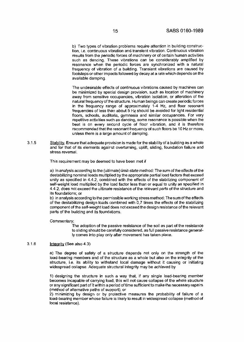
b) Two types of vibration problems require attention in building construc- tion, i.e. continuous vibration and transient vibration. Continuous vibration results from the periodic forces of machinery or of certain human activities such as dancing. These vibrations can be considerably amplified by resonance when the periodic forces are synchronized with a natural frequency of vibration of a building. Transient vibrations are caused by footsteps or other impiacts followed by decay at a rate which depends on the available damping.
The undesirable effects of continuous vibrations caused by machines can be minimized by special design provision, such as location of machinery away from sensitive occupancies, vibration isolation, or alteration of the natural frequency of the structure. Human beings can create periodic forces in the frequency rartge of approximately 1-4 Hz, and floor resonant frequencies of less than about 5 Hz should be avoided for light residential floors, schools, auditoria, gymnasia and similar occupancies. For very repetitive activities such as dancing, some resonance is possible when the beat is on every second cycle of floor vibration, and it is therefore recommended that the resonant frequency of such floors be 10 Hz or more, unless there is a largo amount of damping.
Stability. Ensure that adequate provision is made for the stability of a building as a whole and for that of its elements against overturning, uplift, sliding, foundation failure and stress reversal.
This requirement may be deemed to have been met if
a) in analysis according to the (ultimate) lirnit-state method: The sum of the effects of the destabilizing nominal loads multiplied by the appropriate partial load factors that exceed unity as specified in 4.4.2, combined with the effects of the stabilizing component of self-weight load multiplied by the load factor less than or equal to unity as specified in 4.4.2, does not exceed the ultimate resistance of the relevant parts of the structure and its foundations; or b) in analysis according to the permissible working stress method: The sum of the effects of the destabilizing design loads combined with 0,7 times the effects of the stabilizing component of the self-weight load does not exceed the design resistance of the relevant parts of the building and its foundations.
Commentary: The adoption of the passive resistance of the soil as part of the resistance to sliding should be carefully considered, as full passive resistance general- ly comes into play only after movement has taken place.
lntearity (See also 4.3)
a) The degree of safety of a structure depends not only on the strength of the load-bearing members and of the structure as a whole but also on the integrity of the structure, i.e. its ability to withstand local damage without it causing or initiating widespread collapse. Adequate structural integrity may be achieved by
1) designing the structure in such a way that, if any single load-bearing member becomes incapable of carrying load, this will not cause collapse of the whole structure or any significant part of it within a period of time sufficient to make the necessary repairs (method of alternative paths of support); or 2) minimizing by design or by protective measures the probability of failure of a load-bearing member whose failure is likely to result in widespread collapse (method of local resistance).
SABS 01 60-1 989 16
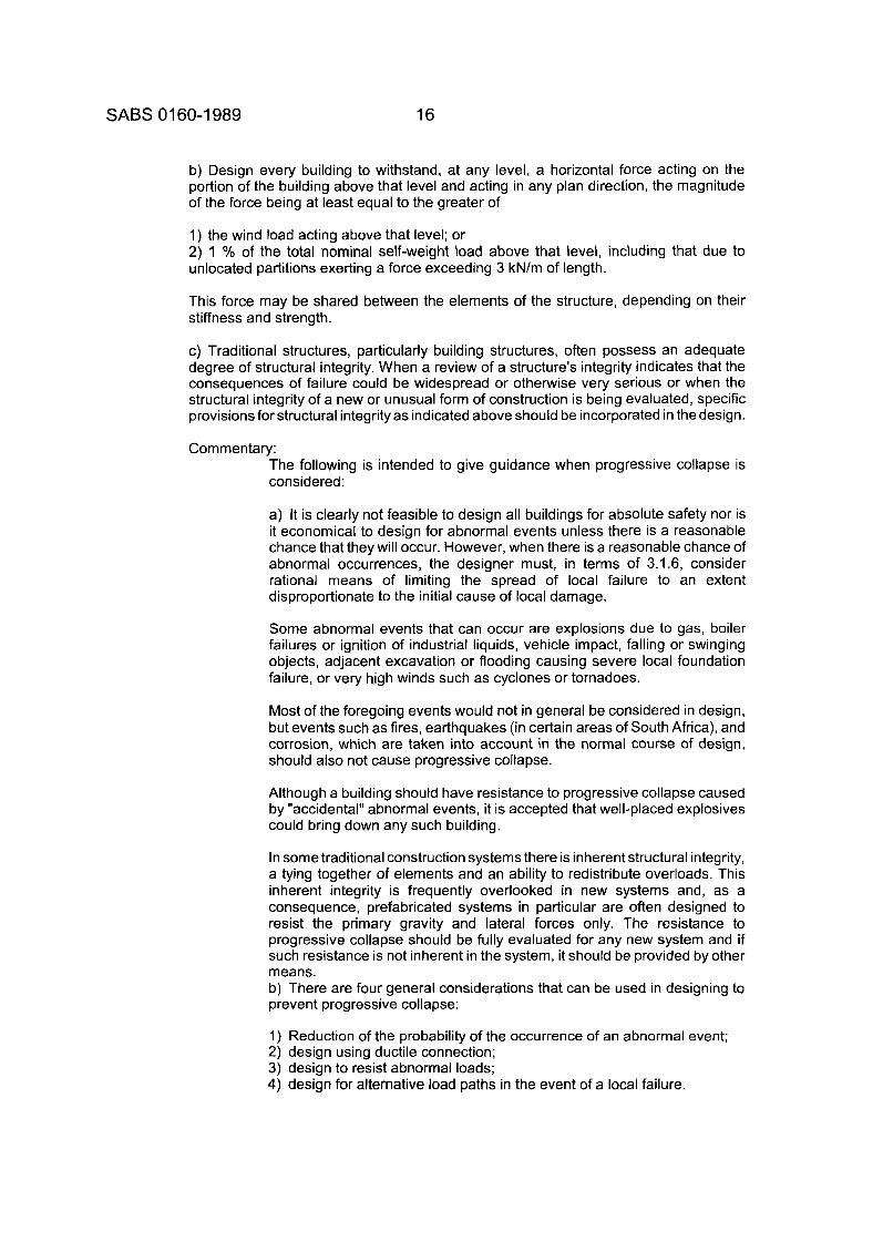
b) Design every building to withstand, at any level, a horizontal force acting on the portion of the building above that level and acting in any plan direction, the magnitude of the force being at least equal to the greater of
1) the wind load acting above that level; or 2) 1 '/o of the total nominal self-weight load above that level, including that due to unlocated partitions exerting a force exceeding 3 kN/m of length.
This force may be shared between the elements of the structure, depending on their stiffness and strength.
c) Traditional structures, particularly building structures, often possess an adequate degree of structural integrity. When a review of a structure's integrity indicates that the consequences of failure could be widespread or otherwise very serious or when the structural integrity of a new or unusual form of construction is being evaluated, specific provisions for structural integrity as indicated above should be incorporated in the design.
Commentary: The following is intended to give guidance when progressive collapse is considered:
a) It is clearly not feasible to design all buildings for absolute safety nor is it economical to design for abnormal events unless there is a reasonable chance that they will occur. However, when there is a reasonable chance of abnormal occurrences, the designer must, in terms of 3.1.6, consider rational means of limiting the spread of local failure to an extent disproportionate to the initial cause of local damage.
Some abnormal events that can occur are explosions due to gas, boiler failures or ignition of industrial liquids, vehicle impact, falling or swinging objects, adjacent excavation or flooding causing severe local foundation failure, or very high winds such as cyclones or tornadoes.
Most of the foregoing events would not in general be considered in design, but events such as fires, earthquakes (in certain areas of South Africa), and corrosion, which are taken into account in the normal course of design, should also not cause progressive collapse.
Although a building should have resistance to progressive collapse caused by "accidental" abnormal events, it is accepted that well-placed explosives could bring down any such building.
In some traditional construction systems there is inherent structural integrity, a tying together of elements and an ability to redistribute overloads. This inherent integrity is frequently overlooked in new systems and, as a consequence, prefabricated systems in particular are often designed to resist the primary gravity and lateral forces only. The resistance to progressive collapse should be fully evaluated for any new system and if such resistance is not inherent in the system, it should be provided by other means. b) There are four general considerations that can be used in designing to prevent progressive collapse:
1) Reduction of the probability of the occurrence of an abnormal event; 2) design using ductile connection; 3) design to resist abnormal loads; 4) design for alternative load paths in the event of a local failure.
17 SABS 01 60-1 989 (As amended 1993)
4.
4.1
4.2
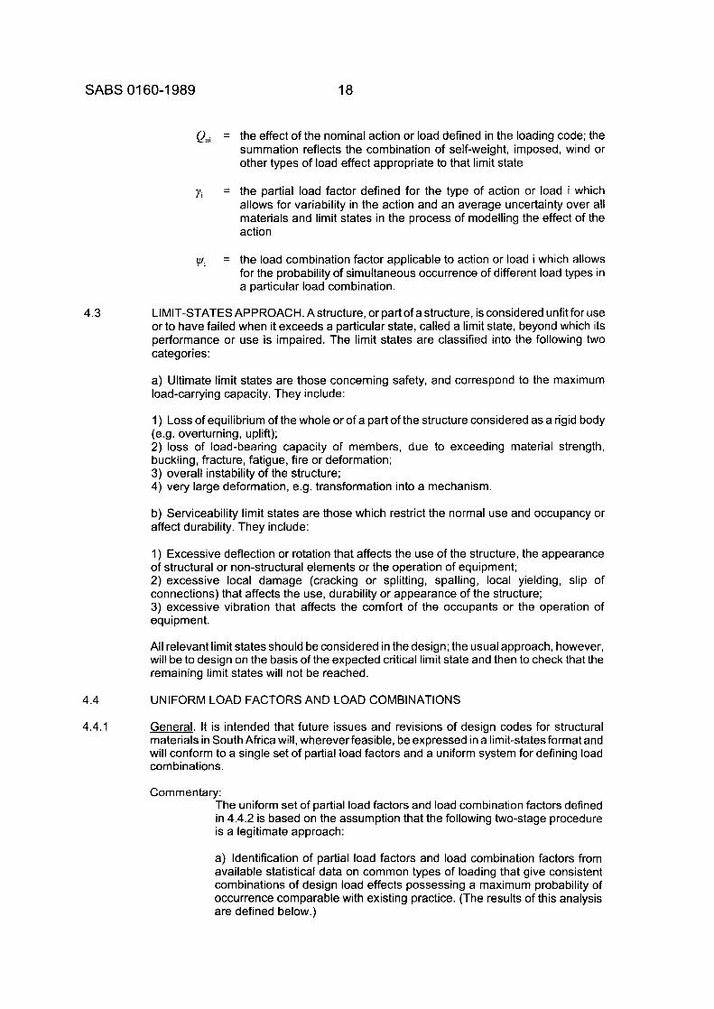
c) It is difficult to apply limits to collapse resulting from an abnormal event; however, it is suggested that collapse be limited,
1) where progression is vertical, to the storey where the event occurred and to the storeys immediately above and below; 2) where the progression is horizontal,
i) to the truss, beam, precast strip floor, or roof panel damaged, and to the one on either side; ii) to a single bay of a full bay-sized floor or roof slab except that where the principal support at one end of a slab is removed, two bay-sized panels may act together as a catenary.
d) Severe deformation is temporarily acceptable in the vicinity of the local failure at the ultimate conditions. A load combination of self-weight load plus one-third of the total of the specified imposed load plus wind load should be used in evaluating the ultimate stability and ultimate strength of the damaged building after the event.
GENERAL GUIDANCE ON LIMIT-STATES DESIGN LOADS
NOTE a) This section is not to be used unless there is a reference to it in the material code. b) See NOTE (b) to Section 5.
GENERAL. This section describes a standardized formulation for preparing limit-states codes for different structural materials. This is achieved through a two-phase process:
a) Acceptance of a set of partial load factors and a uniform system for defining load combinations which would be applicable to all structural materials, as described in 4.4.2. b) Subsequent evaluation of partial material factors, and resistance (or performance) factors appropriate to each limit state in each material code in order to achieve a consistent level of reliability, as described in 4.5.
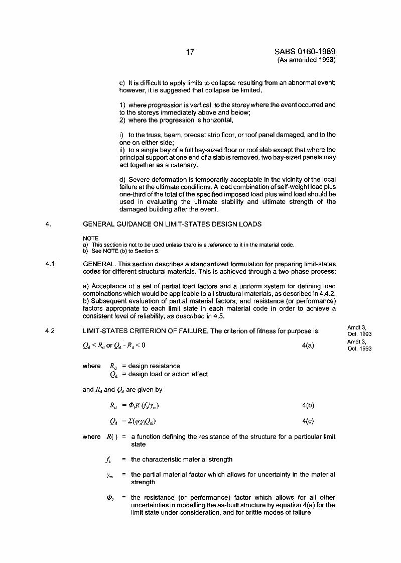
LIMIT-STATES CRITERION OF FAILURE. The criterion of fitness for purpose is: Amdt 3, Oct. 1993
where Rd = design resistance Qd = design load or action effect
and Rd and Qd are given by
where R( ) = a function defining the resistance of the structure for a particular limit state
fk = the characteristic: material strength
ym = the partial material factor which allows for uncertainty in the material strength
Amdt 3, Oct. 1993
@Q = the resistance (or performance) factor which allows for all other
uncertainties in modelling the as-built structure by equation 4(a) for the limit state under [consideration, and for brittle modes of failure
18 SABS 01 60-1 989
QnI =
YI =
4.3
4.4
4.4.1
v / I =
the effect of the nominal action or load defined in the loading code; the summation reflects the combination of self-weight, imposed, wind or other types of load effect appropriate to that limit state
the partial load factor defined for the type of action or load i which allows for variability in the action and an average uncertainty over all materials and limit states in the process of modelling the effect of the action
the load combination factor applicable to action or load i which allows for the probability of simultaneous occurrence of different load types in a particular load Combination.
LIMIT-STATES APPROACH. Astructure, or part of a structure, is considered unfit for use or to have failed when it exceeds a particular state, called a limit state, beyond which its performance or use is impaired. The limit states are classified into the following two categories:
a) Ultimate limit states are those concerning safety, and correspond to the maximum load-carrying capacity. They include:
1) Loss of equilibrium of the whole or of a part of the structure considered as a rigid body (e.g. overturning, uplift); 2) loss of load-bearing capacity of members, due to exceeding material strength, buckling, fracture, fatigue, fire or deformation; 3) overall instability of the structure; 4) very large deformation, e.g. transformation into a mechanism.
b) Serviceability limit states are those which restrict the normal use and occupancy or affect durability. They include:
1) Excessive deflection or rotation that affects the use of the structure, the appearance of structural or non-structural elements or the operation of equipment; 2) excessive local damage (cracking or splitting, spalling, local yielding, slip of connections) that affects the use, durability or appearance of the structure; 3) excessive vibration that affects the comfort of the occupants or the operation of equipment.
All relevant limit states should be considered in the design; the usual approach, however, will be to design on the basis of the expected critical limit state and then to check that the remaining limit states will not be reached.
UNIFORM LOAD FACTORS AND LOAD COMBINATIONS
General. It is intended that future issues and revisions of design codes for structural materials in South Africa will, whereverfeasible, be expressed in a limit-states format and will conform to a single set of partial load factors and a uniform system for defining load com binations.
Cornrnen tary: The uniform set of partial load factors and load combination factors defined in 4.4.2 is based on the assumption that the following two-stage procedure is a legitimate approach:
a) Identification of partial load factors and load combination factors from available statistical data on common types of loading that give consistent combinations of design load effects possessing a maximum probability of occurrence comparable with existing practice. (The results of this analysis are defined below.)
19 SABS 01 60-1 989 (As amended 1991 and 1993)
4.4.2
b) Identification of partial material factors for each structural material and partial resistance factors for each limit state that, from available statistical data on resistance of different limit states, give consistent probabilities of failure, using the loading information obtained from (a) above. (This assessment will be undertaken by the individual code committees for the different structural codes.)
This is different from the approach adopted in North America and Australia, where the assessment of each limit state and load combination is under- taken ab initio, allowing for variability in both load effect and resistance. A practical problem associated with a full reliability analysis of this type is that the statistics of both the load effect and the resistance of the member are required. In South Africa, statistics for member resistance, related to the relevant materials codes, are largely unavailable at present and it would be a lengthy process to collect the necessary information. A further problem is that several of the materials codes are still in the process of preparation and it is also anticipated that some of the existing codes may undergo major revisions in the future.
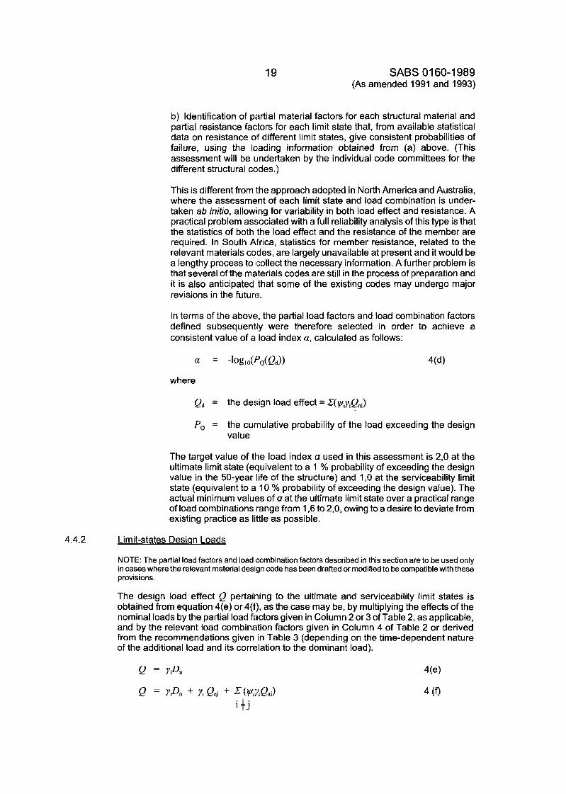
In terms of the above, the partial load factors and load combination factors defined subsequently were therefore selected in order to achieve a consistent value of a load index a, calculated as follows:
where
Qd = the design load effect = Z(wiyiQni)
PQ = the curnulative probability of the load exceeding the design value
The target value of the load index a used in this assessment is 2,O at the ultimate limit state (equivalent to a 1 % probability of exceeding the design value in the 50-year life of the structure) and 1 ,O at the serviceability limit state (equivalent to a 10 % probability of exceeding the design value). The actual minimum values of a at the ultimate limit state over a practical range of load combinations range from 1,6 to 2,0, owing to a desire to deviate from existing practice as little as possible.
Limit-states Desian Loads
NOTE: The partial load factors and load combination factors described in this section are to be used only in cases where the relevant material design code has been drafted or modified to be compatible with these provisions.
The design load effect Q pertaining to the ultimate and serviceability limit states is obtained from equation 4(e) or 4(f), as the case may be, by multiplying the effects of the nominal loads by the partial load factors given in Column 2 or 3 of Table 2, as applicable, and by the relevant load combination factors given in Column 4 of Table 2 or derived from the recommendations given in Table 3 (depending on the time-dependent nature of the additional load and its correlation to the dominant load).
SABS 1060-1 989 (As amended 1991 and 1993)
20
where
Amdt 3, Oct. 1993
Amdt 3, Oct. 1993
Amdt 3. Oct. 1993
yi = the partial load factors given in Table 2
D, = the nominal permanent load effect
Q, = the dominant imposed load effect for the load combinations and limit state under consideration
Qni = additional imposed load effects relevant and significant to the load combination and limit state under consideration
t,ui = the load combination factors given in Tables 2 and 3
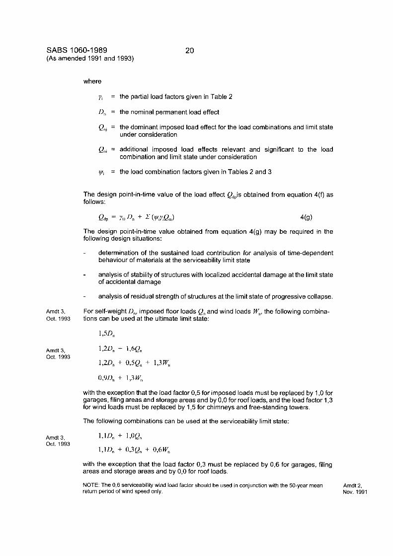
The design point-in-time value of the load effect Qdpis obtained from equation 4(f) as follows:
Qdp = YD Dn + 2 ( V i Y i Q n J 4(9)
The design point-in-time value obtained from equation 4(g) may be required in the following design situations:
- determination of the sustained load contribution for analysis of time-dependent behaviour of materials at the serviceability limit state
- analysis of stability of structures with localized accidental damage at the limit state of accidental damage
analysis of residual strength of structures at the limit state of progressive collapse. -
For self-weight D,, imposed floor loads Q, and wind loads W,, the following combina- tions can be used at the ultimate limit state:
with the exception that the load factor 0,5 for imposed loads must be replaced by 1 ,O for garages, filing areas and storage areas and by 0,O for roof loads, and the load factor 1,3 for wind loads must be replaced by 1,5 for chimneys and free-standing towers.
The following combinations can be used at the serviceability limit state:
171Dn + 1,OQn
l,lD, + 0,3Q, + 0,6W,
with the exception that the load factor 0,3 must be replaced by 0,6 for garages, filing areas and storage areas and by 0,O for roof loads.
NOTE: The 0,6 serviceability wind load factor should be used in conjunction with the 50-year mean return period of wind speed only.
Amdt 2, Nov. 1991
21 SABS 01 60-1 989 (As amended 1991 and 1993)
The sustained portion of the loads at the serviceability limit state is obtained from
1,lQ + 0,3Qn
with the same proviso on the factor 0,3 as above.
The design load effect may be adjusted at the discretion of the designer by multiplying the design load effect in equation 4(e) and 4(f) by an importance factor yc to allow for the consequences of failure. In the case of critical structural members of structures in which large numbers of the public gather and where there would be "very serious" con- sequences of a failure, a value of yc in the range 1,1-1,2 should be used. For structures with a very low degree of hazard to life and "not serious" consequences of failure, a value of yc of 0,9 would be appropriate.
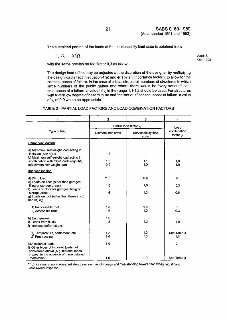
TABLE 2 - PARTIAL LOAD FACTORS AND LOAD COMBINATION FACTORS
1
Type of load
Permanent loadinq
a) Maximum self-weight load acting in isolation (eqn 4(e))
b) Maximum self-weight load acting in combination with other loads (eqn 4(9)
c)Minimum self-weight load
Imposed loading
d) Wind load e) Loads on floor (other than garages, filing or storage areas)
f) Loads on floor for garages, filing or storage areas
g) Loads on roof (other than those in (d) and (h)-(l))
1) Inaccessible roof 2) Accessible roof
h) Earthquakes i) Loads from fluids j) Imposed deformations
1) Temperature, settlement, etc. 2) Prestressing
k) Accidental loads I) Other types of imposed loads not considered above (e.g. material loads, cranes) in the absence of more detailed information
I
Partial load factor Y;
Ultimate limit state Serviceability limit state
1 ,o 1 .o
1 .o
4
Load combination
factor i,ui
1 ,o 1 ,o
0
0.3
0,6
See Table 3 1 ,o 0
See Table 3
Amdt 3, Oct. 1993
1 3 for slender non-redundant structures such as chimneys and free-standing towers that exhibit significant cross-wind response.
SABS 1060-1 989 (As amended 1991 and 1993)
22
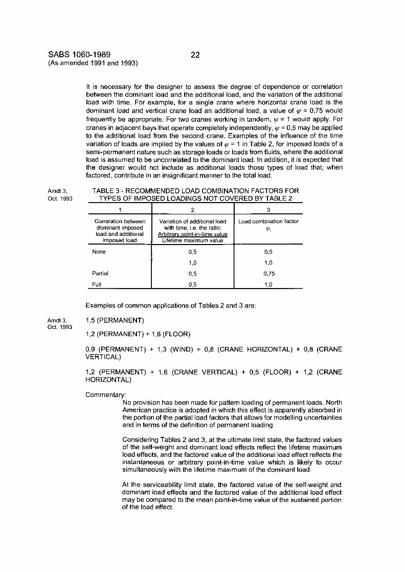
It is necessary for the designer to assess the degree of dependence or correlation between the dominant load and the additional load, and the variation of the additional load with time. For example, for a single crane where horizontal crane load is the dominant load and vertical crane load an additional load, a value of cy = 0,75 would frequently be appropriate. For two cranes working in tandem, cy = 1 would apply. For cranes in adjacent bays that operate completely independently, cy = 0,5 may be applied to the additional load from the second crane. Examples of the influence of the time variation of loads are implied by the values of cy = 1 in Table 2, for imposed loads of a semi-permanent nature such as storage loads or loads from fluids, where the additional load is assumed to be uncorrelated to the dominant load. In addition, it is expected that the designer would not include as additional loads those types of load that, when factored, contribute in an insignificant manner to the total load.
Amdt 3, TABLE 3 - RECOMMENDED LOAD COMBINATION FACTORS FOR Oct. 1993 TYPES OF IMPOSED LOADINGS NOT COVERED BY TABLE 2
I I
Correlation between dominant imposed load and additional
imposed load
None
Partial
Variation of additional load with time, i.e. the ratio:
Arbitrarv point-in-time value Lifetime maximum value
0,s
1 ,o 0 3
3
Load combination factor '+"i
Examples of common applications of Tables 2 and 3 are:
Amdt 3, 1 3 (PERMANENT) Oct. 1993
1,2 (PERMANENT) + 1,6 (FLOOR)
0,9 (PERMANENT) + 1,3 (WIND) + 0,8 (CRANE HORIZONTAL) + 0,8 (CRANE VERTICAL)
1,2 (PERMANENT) + 1,6 (CRANE VERTICAL) + 0,5 (FLOOR) + 1,2 (CRANE HORIZONTAL)
Commentary: No provision has been made for pattern loading of permanent loads. North American practice is adopted in which this effect is apparently absorbed in the portion of the partial load factors that allows for modelling uncertainties and in terms of the definition of permanent loading.
Considering Tables 2 and 3, at the ultimate limit state, the factored values of the self-weight and dominant load effects reflect the lifetime maximum load effects, and the factored value of the additional load effect reflects the instantaneous or arbitrary point-in-time value which is likely to occur simultaneously with the lifetime maximum of the dominant load.
At the serviceability limit state, the factored value of the self-weight and dominant load effects and the factored value of the additional load effect may be compared to the mean point-in-time value of the sustained portion of the load effect.
SABS 01 60-1 989 23
4.5
4.5.1
4.5.2
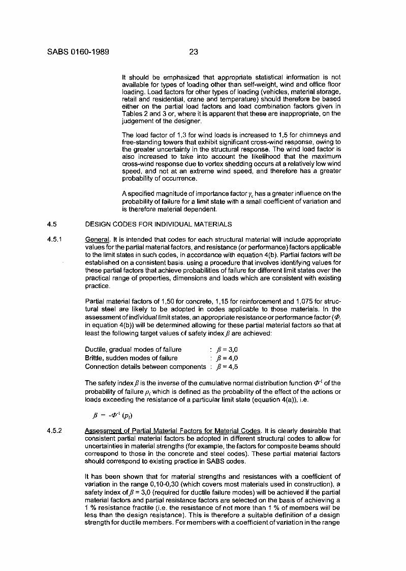
It should be emphasized that appropriate statistical information is not available for types of loading other than self-weight, wind and office floor loading. Load factors for other types of loading (vehicles, material storage, retail and residential, crane and temperature) should therefore be based either on the partial load factors and load combination factors given in Tables 2 and 3 or, where it is apparent that these are inappropriate, on the judgement of the designer.
The load factor of 1,3 for wind loads is increased to 1 3 for chimneys and free-standing towers that exhibit significant cross-wind response, owing to the greater uncertainty in the structural response. The wind load factor is also increased to take into account the likelihood that the maximum cross-wind response due to vortex shedding occurs at a relatively low wind speed, and not at an extreme wind speed, and therefore has a greater probability of occurrence.
A specified magnitude of importance factory, has a greater influence on the probability of failure for a limit state with a small coefficient of variation and is therefore material dependent.
DESIGN CODES FOR INDIVIDUAL MATERIALS
General. It is intended that codes for each structural material will include appropriate values for the partial material factors, and resistance (or performance) factors applicable to the limit states in such codes, in accordance with equation 4(b). Partial factors will be established on a consistent basis, using a procedure that involves identifying values for these partial factors that achieve probabilities of failure for different limit states over the practical range of properties, dimensions and loads which are consistent with existing practice.
Partial material factors of 1,50 for concrete, 1 ,I 5 for reinforcement and 1,075 for struc- tural steel are likely to be adopted in codes applicable to those materials. In the assessment of individual limit states, an appropriate resistance or performance factor (@@ in equation 4(b)) will be determined allowing for these partial material factors so that at least the following target values of safety index@ are achieved:
Ductile, gradual modes of failure : J'= 3,O Brittle, sudden modes of failure : @=4,0 Connection details between components : @ = 4 3
The safety index@ is the inverse of the cumulative normal distribution function @-' of the probability of failure pf which is defined as the probability of the effect of the actions or loads exceeding the resistance of a particular limit state (equation 4(a)), i.e.
Assessment of Partial Material Factors for Material Codes. It is clearly desirable that consistent partial material factors be adopted in different structural codes to allow for uncertainties in material strengths (for example, the factors for composite beams should correspond to those in the concrete and steel codes). These partial material factors should correspond to existing practice in SABS codes.
It has been shown that for material strengths and resistances with a coefficient of variation in the range 0,lO-0,30 (which covers most materials used in construction), a safety index of@ = 3,O (required for ductile failure modes) will be achieved if the partial material factors and partial resistance factors are selected on the basis of achieving a 1 % resistance fractile (i.e. the resistance of not more than 1 % of members will be less than the design resistance). This is therefore a suitable definition of a design strength for ductile members. For members with a coefficient of variation in the range
SABS 1060-1 989 24 (As amended 1991 and 1993)
5.
5.1
5.1 .I
5.1.2
5.2
5.2.1
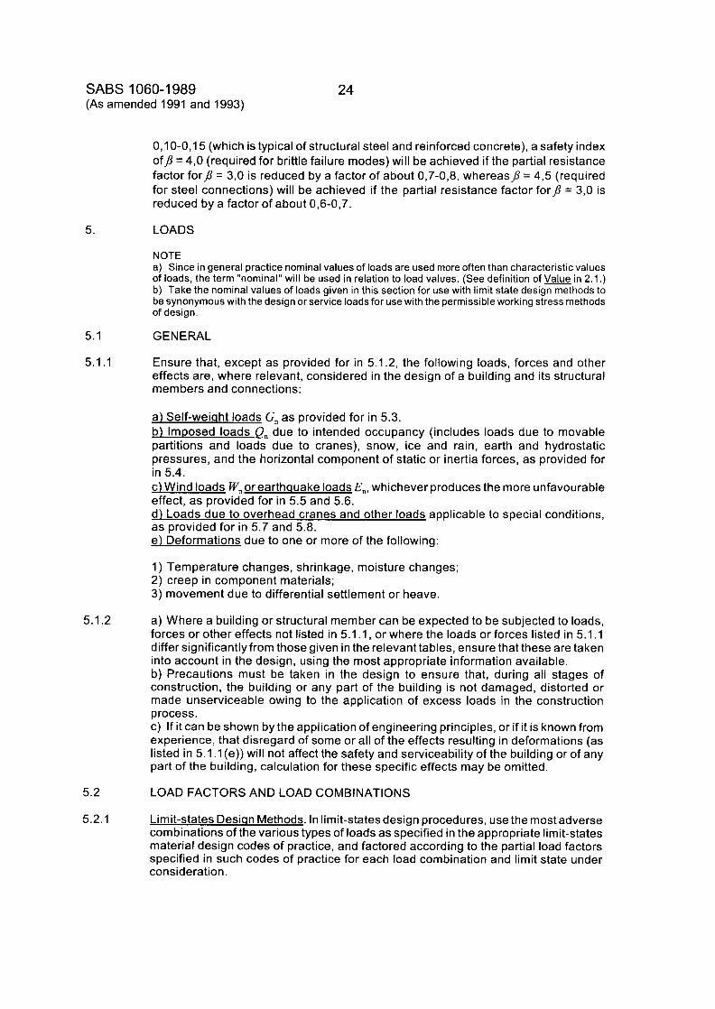
0,lO-0,15 (which is typical of structural steel and reinforced concrete), a safety index ofJ = 4,O (required for brittle failure modes) will be achieved if the partial resistance factor forJ = 3,O is reduced by a factor of about 0,7-0,8, whereasp = 4,5 (required for steel connections) will be achieved if the partial resistance factor forJ = 3,O is reduced by a factor of about 0,6-0,7.
LOADS
NOTE a) Since in general practice nominal values of loads are used more often than characteristic values of loads, the term "nominal" will be used in relation to load values. (See definition of in 2.1 .) b) Take the nominal values of loads given in this section for use with limit state design methods to be synonymous with the design or service loads for use with the permissible working stress methods of design .
GENERAL
Ensure that, except as provided for in 5.1.2, the following loads, forces and other effects are, where relevant, considered in the design of a building and its structural members and connections:
a) Self-weiuht loads G, as provided for in 5.3. b) ImDosed loads Q, due to intended occupancy (includes loads due to movable partitions and loads due to cranes), snow, ice and rain, earth and hydrostatic pressures, and the horizontal component of static or inertia forces, as provided for in 5.4. c) Wind loads W, or earthuuake loads E,, whichever produces the more unfavourable effect, as provided for in 5.5 and 5.6. d) Loads due to overhead cranes and other loads applicable to special conditions, as provided for in 5.7 and 5.8. e l Deformations due to one or more of the following:
1) Temperature changes, shrinkage, moisture changes; 2) creep in component materials; 3) movement due to differential settlement or heave.
a) Where a building or structural member can be expected to be subjected to loads, forces or other effects not listed in 5.1 . I , or where the loads or forces listed in 5.1 . I differ significantlyfrom those given in the relevant tables, ensure that these are taken into account in the design, using the most appropriate information available. b) Precautions must be taken in the design to ensure that, during all stages of construction, the building or any part of the building is not damaged, distorted or made unserviceable owing to the application of excess loads in the construction process. c) If it can be shown by the application of engineering principles, or if it is known from experience, that disregard of some or all of the effects resulting in deformations (as listed in 5.1 . I (e)) will not affect the safety and serviceability of the building or of any part of the building, calculation for these specific effects may be omitted.
LOAD FACTORS AND LOAD COMBINATIONS
Limit-states Desian Methods. In limit-states design procedures, use the most adverse combinations of the various types of loads as specified in the appropriate limit-states material design codes of practice, and factored according to the partial load factors specified in such codes of practice for each load combination and limit state under consideration.
25 SABS 01 60-1 989 (As amended 1993)
5.2.2
5.3
5.3.1
5.3.2
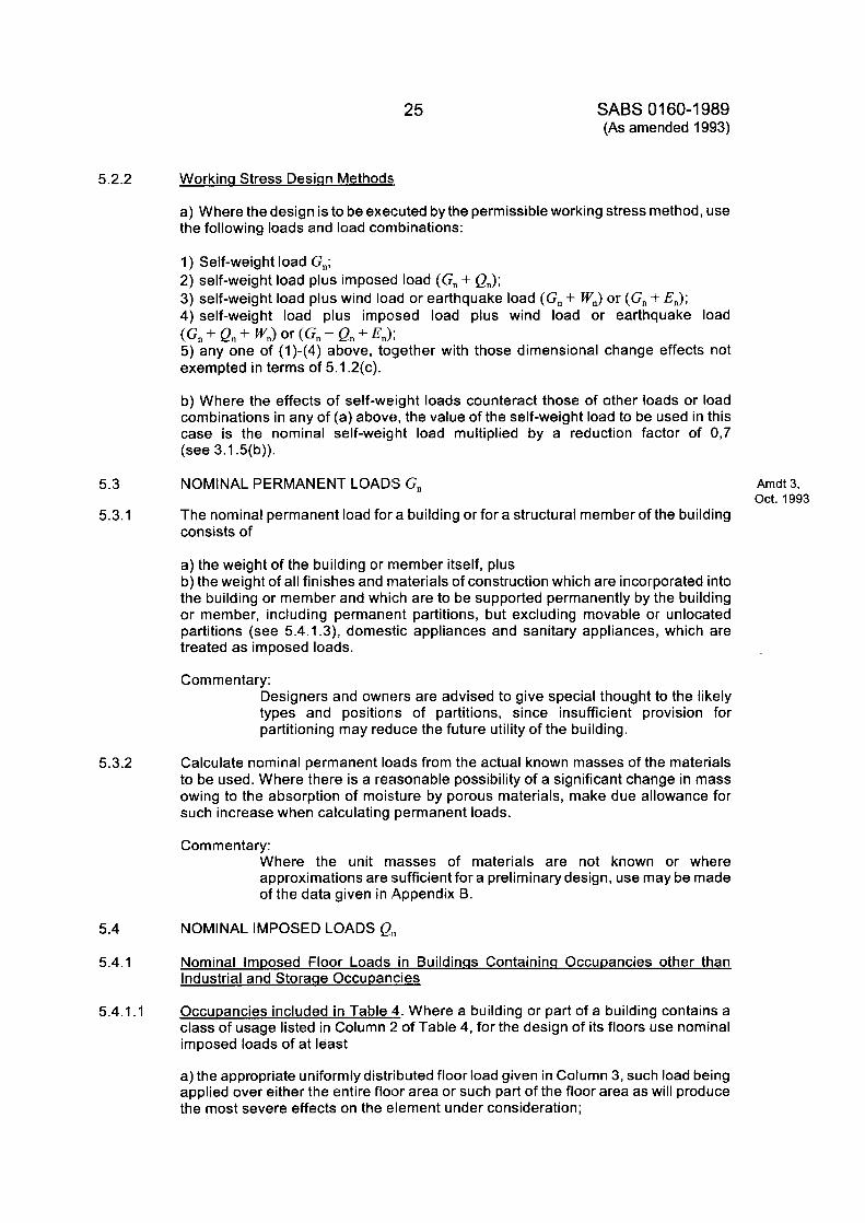
Workina Stress Desian Methods.
a) Where the design is to be executed by the permissible working stress method, use the following loads and load combinations:
1) Self-weight load G,; 2) self-weight load plus imposed load (G, + Q,J; 3) self-weight load plus wind load or earthquake load (G, + W,) or (G, + En); 4) self-weight load plus imposed load plus wind load or earthquake load
5) any one of (1)-(4) above, together with those dimensional change effects not exempted in terms of 5.1.2(c).
(Gn + Qn + W,J or (Gn + Qn + E,);
b) Where the effects of self-weight loads counteract those of other loads or load combinations in any of (a) above, the value of the self-weight load to be used in this case is the nominal self-weight load multiplied by a reduction factor of 0,7 (see 3.1.5(b)).
NOMINAL PERMANENT LOADS G,
The nominal permanent load for a building or for a structural member of the building consists of
Arndt 3, Oct. 1993
a) the weight of the building or rnember itself, plus b) the weight of all finishes and materials of construction which are incorporated into the building or member and which are to be supported permanently by the building or member, including permanent partitions, but excluding movable or unlocated partitions (see 5.4.1.3), domestic appliances and sanitary appliances, which are treated as imposed loads.
Commentary: Designers and owners are advised to give special thought to the likely types and positions of partitions, since insufficient provision for partitioning may reduce the future utility of the building.
Calculate nominal permanent loads from the actual known masses of the materials to be used. Where there is a reasonable possibility of a significant change in mass owing to the absorption of moisture by porous materials, make due allowance for such increase when calculating permanent loads.
Com men tary : Where the unit masses of materials are not known or where approximations are sufficient for a preliminarydesign, use may be made of the data given in Appendix B.
5.4 NOMINAL IMPOSED LOADS Q,,
5.4.1 Nominal Imposed Floor Loads in Buildinas Containinq Occupancies other than Industrial and Storaae Occupancies
5.4.1.1 Occupancies included in Table 4. Where a building or part of a building contains a class of usage listed in Column 2 of Table 4, for the design of its floors use nominal imposed loads of at least
a) the appropriate uniformly distributed floor load given in Column 3, such load being applied over either the entire floor area or such part of the floor area as will produce the most severe effects on the element under consideration;
SABS 01 60-1 989 (As amended 1993)
26
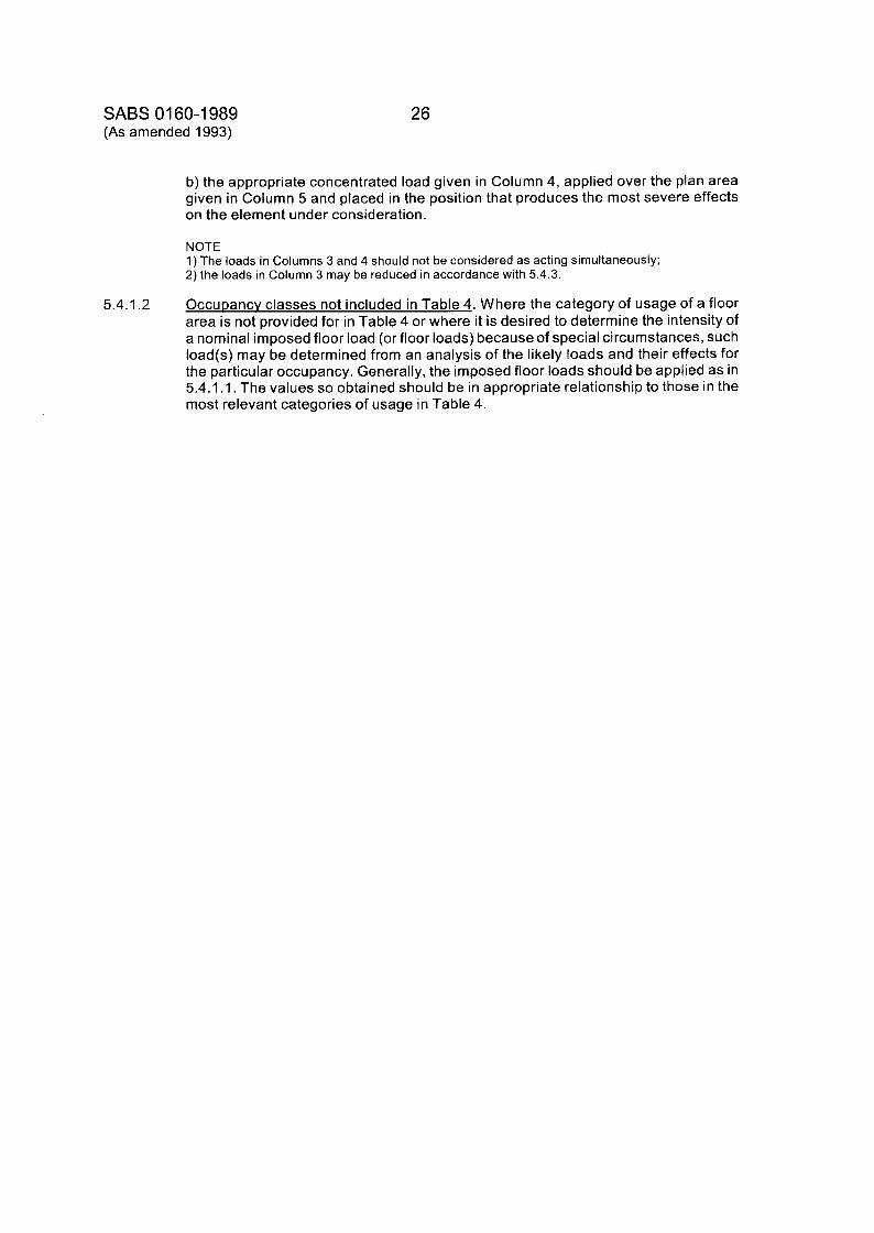
b) the appropriate concentrated load given in Column 4, applied over the plan area given in Column 5 and placed in the position that produces the most severe effects on the element under consideration.
NOTE 1) The loads in Columns 3 and 4 should not be considered as acting simultaneously; 2) the loads in Column 3 may be reduced in accordance with 5.4.3.
OccuDancv classes not included in Table 4. Where the category of usage of a floor area is not provided for in Table 4 or where it is desired to determine the intensity of a nominal imposed floor load (or floor loads) because of special circumstances, such load(s) may be determined from an analysis of the likely loads and their effects for the particular occupancy. Generally, the imposed floor loads should be applied as in 5.4.1 .I. The values so obtained should be in appropriate relationship to those in the most relevant categories of usage in Table 4.
5.4.1.2
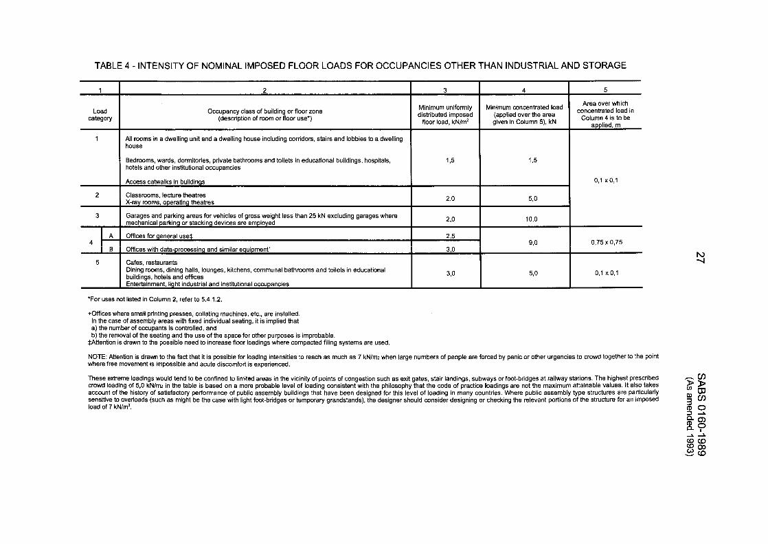
TABLE 4 - INTENSITY OF NOMINAL IMPOSED FLOOR LOADS FOR OCCUPANCIES OTHER THAN INDUSTRIAL AND STORAGE
2
3
A
€3 4
5
Load I category
Access catwalks in buildings 0, l x 0,l
2,o 5,O
2,o 10,o
Classrooms, lecture theatres X-ray rooms, operating theatres
Garages and parking areas for vehicles of gross weight less than 25 kN excluding garages where mechanical parking or stacking devices are employed
Offices for general use* 2 3 0,75 x 0,75
offices with data-processing and similar equipment*
Cafes, restaurants Dining rooms, dining halls, lounges, kitchens, communal bathrooms and toilets in educational buildings, hotels and offices Entertainment, light industrial and institutional occupancies
9,o 3,O
3,O 5,O 0,l x 0,l
Occupancy class of building or floor zone (description of room or floor use')
Minimum uniformly distributed imposed
floor load, kN/m2
I All rooms in a dwelling unit and a dwelling house including corridors, stairs and lobbies to a dwelling house I 1
I Bedrooms. wards, dormitories, private bathrooms and toilets in educational buildings, hospitals, hotels and other institutional occupancies I 1.5 15
ro -4
'For uses not listed in Column 2, refer to 5.4.1.2.
+Offices where small printing presses, collating machines, etc., are installed. In the case of assembly areas with fixed individual seating, it is implied that a) the number of occupants is controlled, and b) the removal of the seating and the use of the space for other purposes is improbable.
$Attention is drawn to the possible need to increase floor ioadings where compacted filing systems are used.
NOTE: Attention is drawn to the fact that it is possible for loading intensities to reach as much as 7 kNlm2 when large numbers of people are forced by panic or other urgencies to crowd together to the point where free movement is impossible and acute discomfort is experienced.
These extreme loadings would tend to be confined to limited areas in the vicinity of points of congestion such as exit gates, stair landings, subways or foot-bridges at railway stations. The highest prescribed crowd loading of 5,O kN/mz in the table is based on a more probable level of loading consistent with the philosophy that the code of practice loadings are not the maximum attainable values. It alSO takes
,cn 2g
load of 7 kN/m2. :a $6
account of the history of satisfactory performance of public assembly buildings that have been designed for this level of loading in many countries. Where public assembly type structures are PartiCUlarlY sensitive to overloads (such as might be the case with light foot-bridges or temporary grandstands), the designer should consider designing or checking the relevant portions of the structure for an imposed
Q ?
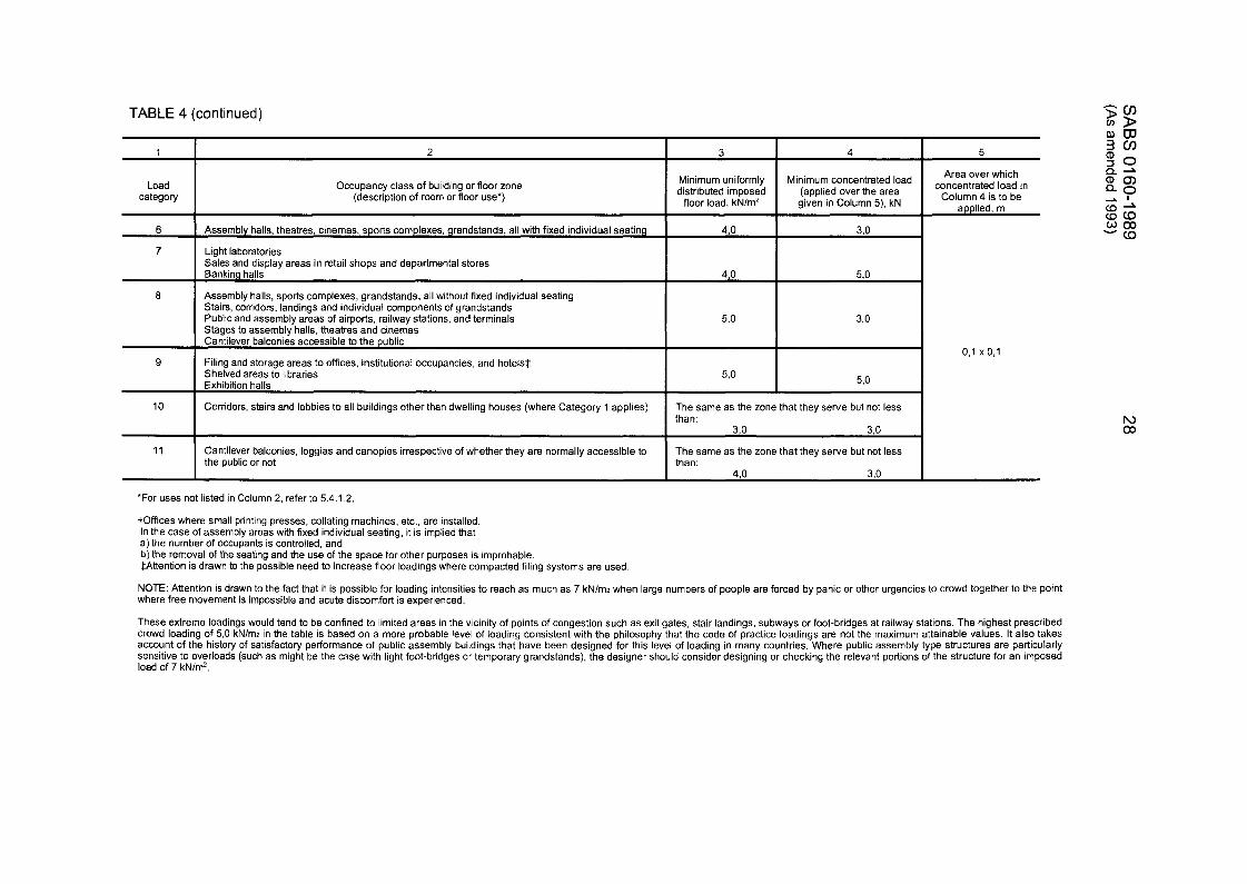
TABLE 4 (continued)
Load category
Area over which Minimum uniformly Minimum concentrated load concentrated load in distributed imposed (applied over the area
given in Column 5), kN Co'umn is to be floor load, kN/m2
Occupancy class of building or floor zone (description of room or floor use*)
applied, m
6
7
0
9
I 10 I Corridors, stairs and lobbies to all buildings other than dwelling houses (where Category 1 applies) The same as the zone that they serve but not less I than:
Assembly halls, theatres, cinemas, sports complexes, grandstands, all with fixed individual seating
Light laboratories Sales and display areas in retail shops and departmental stores Banking halls 4,O 5.0
Assembly halls, sports complexes, grandstands, all without fixed individual seating Stairs, corridors, landings and individual components of grandstands Public and assembly areas of airports, railway stations, and terminals Stages to assembly halls, theatres and cinemas Cantilever balconies accessible to the public
Filing and storage areas to offices, institutional occupancies, and hotels* Shelved areas to libraries 5 0 Exhibition halls
4.0 3,O
5.0 3,O
5,O
0,l x 0 , l
11 Cantilever balconies, loggias and canopies irrespective of whether they are normally accessible to the public or not than:
The same as the zone that they serve but not less
4,O 3,O
29 SABS 01 60-1 989 (As amended 1993)
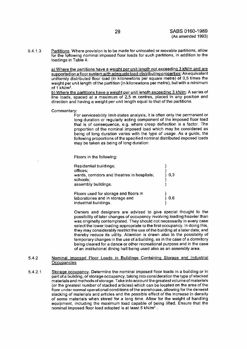
5.4.1.3 Partitions. Where provision is to be made for unlocated or movable partitions, allow for the following nominal imposed floor loads for such partitions, in addition to the loadings in Table 4:
a) Where the partitions have a weiaht Der unit lenqth not exceedina 3 kN/m and are SUDDOrted on a floor svstem with adeauate load-distributina DroDerties: An equivalent uniformly distributed floor load (in kilonewtons per square metre) of 0,5 times the weight per unit length of the partition (in kilonewtons per metre), but with a minimum of 1 kN/m2. b) Where the Dartitions have a weiqht Der unit lenqth exceedina 3 kN/m: A series of line loads, spaced at a maximum of 2,5 m centres, placed in any position and direction and having a weight per unit length equal to that of the partitions.
Commentary: For serviceability limit-states analysis, it is often only the permanent or long duration or regularly acting component of the imposed floor load that is of consequence, e.g. where creep deflection is a factor. The proportion of the nominal imposed load which may be considered as being of long duration varies with the type of usage. As a guide, the following proportions of the specified nominal distributed imposed loads may be taken as being of long duration:
Floors in the following:
Residential buildings; ) offices ; ) wards, corridors ancl theatres in hospitals; schools; ) assembly buildings. )
) 0,3
Floors used for storage and floors in ) laboratories and in storage and ) 0,6 industrial buildings. )
Owners and designers are advised to give special thought to the possibility of later changes of occupancy involving loading heavier than was originally contemplated. They should not necessarily in every case select the lower loading appropriate to the first occupancy. In doing this, they may considerably restrict the use of the building at a later date, and thereby reduce its utility. Attention is drawn also to the possibility of temporary changes in the use of a building, as in the case of a dormitory being cleared for a dance or other recreational purpose and in the case of an institutional dining hall being used also as an assembly area.
5.4.2 Nominal Imposed Floor Loads in Buildinas Containina Storage and Industrial OccuDancies
5.4.2.1 Storaae OccuDancv. Determine the nominal imposed floor loads in a building or in part of a building, of storage occupancy, taking into consideration the type of stacked materials and methods of storage. Take into account the greatest volume of materials (or the greatest number of stacked articles) which can be located on the area of the floor under normal operational conditions of the warehouse, allowing for the densest stacking of materials and articles and the possible effect of the increase in density of some materials when stored for a long time. Allow for the weight of handling equipment, including the maximum load capable of being lifted. Ensure that the nominal imposed floor load adopted is at least 5 kN/m2.
SABS 01 60-1 989 (As amended 1993)
30
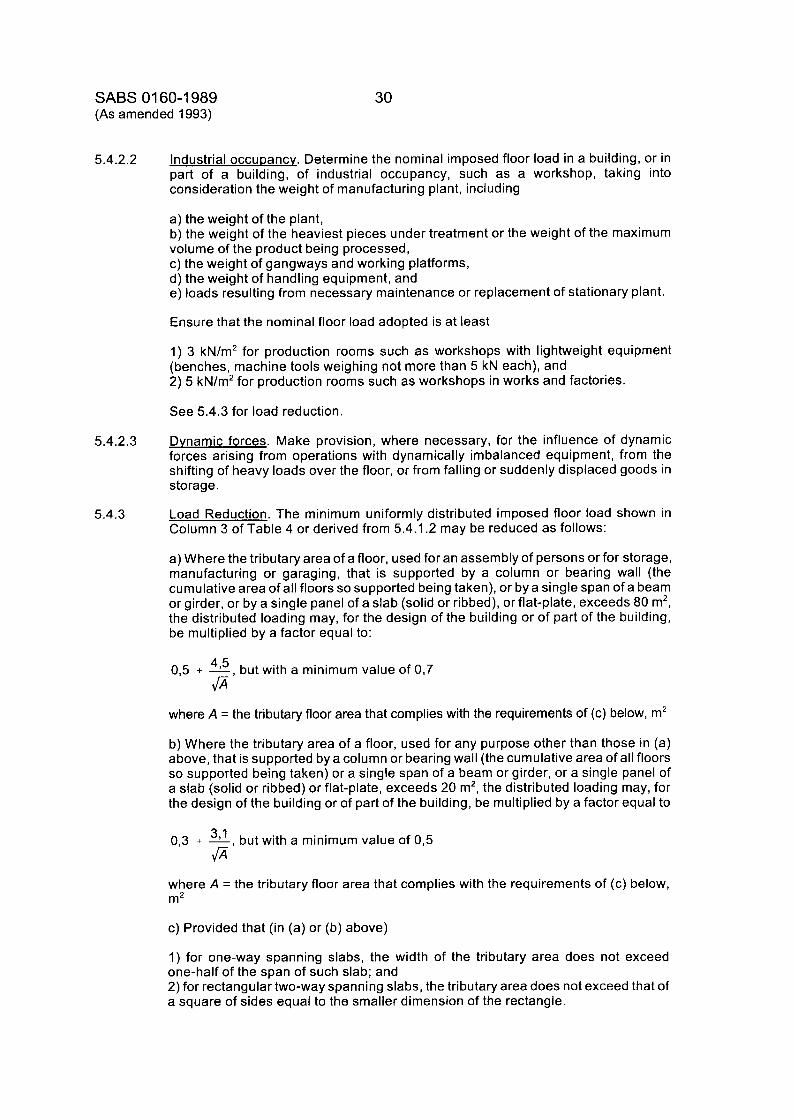
5.4.2.2 Industrial OccuDancv. Determine the nominal imposed floor load in a building, or in part of a building, of industrial occupancy, such as a workshop, taking into consideration the weight of manufacturing plant, including
a) the weight of the plant, b) the weight of the heaviest pieces under treatment or the weight of the maximum volume of the product being processed, c) the weight of gangways and working platforms, d) the weight of handling equipment, and e) loads resulting from necessary maintenance or replacement of stationary plant.
Ensure that the nominal floor load adopted is at least
1) 3 kN/m2 for production rooms such as workshops with lightweight equipment (benches, machine tools weighing not more than 5 kN each), and 2) 5 kN/m2 for production rooms such as workshops in works and factories.
See 5.4.3 for load reduction.
5.4.2.3 Dynamic forces. Make provision, where necessary, for the influence of dynamic forces arising from operations with dynamically imbalanced equipment, from the shifting of heavy loads over the floor, or from falling or suddenly displaced goods in storage.
5.4.3 Load Reduction. The minimum uniformly distributed imposed floor load shown in Column 3 of Table 4 or derived from 5.4.1.2 may be reduced as follows:
a) Where the tributary area of a floor, used for an assembly of persons or for storage, manufacturing or garaging, that is supported by a column or bearing wall (the cumulative area of all floors so supported being taken), or bya single span of a beam or girder, or by a single panel of a slab (solid or ribbed), or flat-plate, exceeds 80 m2, the distributed loading may, for the design of the building or of part of the building, be multiplied by a factor equal to:
0,5 + - 4’5, but with a minimum value of 0,7
where A = the tributary floor area that complies with the requirements of (c) below, m2
@
b) Where the tributary area of a floor, used for any purpose other than those in (a) above, that is supported by a column or bearing wall (the cumulative area of all floors so supported being taken) or a single span of a beam or girder, or a single panel of a slab (solid or ribbed) or flat-plate, exceeds 20 m2, the distributed loading may, for the design of the building or of part of the building, be multiplied by a factor equal to
0,3 + g, but with a minimum value of 0,5 @
where A = the tributary floor area that complies with the requirements of (c) below, m2
c) Provided that (in (a) or (b) above)
1) for one-way spanning slabs, the width of the tributary area does not exceed one-half of the span of such slab; and 2) for rectangular two-way spanning slabs, the tributary area does not exceed that of a square of sides equal to the smaller dimension of the rectangle.
31 SABS 01 60-1 989 (As amended 1993)
5.4.4 Nominal Imposed Roof Loads
NOTE: In this subsection, all roof slopes are measured from the horizontal and all imposed loads act in a vertical direction.
5.4.4.1 General. So design all roofs that they are capable of sustaining the relevant nominal imposed loads set out in 5.4.4.2-5.4.4.6 (inclusive) in addition to the wind loads detailed in 5.5, but:
a) for inaccessible roofs the nominal imposed roof loads and nominal wind loads shall not be taken as acting concurrently; and b) for accessible roofs 0,3 times the nominal imposed roof load shall be taken as acting concurrently with the nominal wind load.
Com m en tary: These are primarily maintenance or construction loads intended to represent the effects of workmen or stacked materials, etc. Alternatively, the distributed load will cater for limited accumulations of snow, hail or rainwater on roofs (approximately 250 mm depth of snow, 60 mm of hail or 50 mm of rainwater, measured vertically).
NOTE: Wind loading will usually be predominant where the roof slope is less than 30".
5.4.4.2 Accessible flat roof
a) Where access is provided to a flat roof (in addition to access necessary for cleaning and repair), allow for a uniformly distributed imposed load of 2,O kN/m2 measured on plan, or a concentrated load of 2,O kN applied over an area of 0 , l m x 0 , l m, whichever is more severe. b) When a roof has an intended use as a floor, design it in accordance with 5.4.1 or 5.4.2, as appropriate.
5.4.4.3 Inaccessible roof. Where no access is provided to a roof (other than that necessary for cleaning and repair), allow for one of the following nominal loads, whichever is the most severe:
a) A concentrated load of 0,9 kN, acting vertically downward and applied over an area of 0 , l m x 0 , l m in any position; or b) a uniformly distributed load, acting vertically downward, of
(0,3 + - 5-A) kN/m 60
where A = the tributary area for the member under consideration or the area of the roof slab confined by the perimeter of supporting members, measured on plan, m2, as appropriate
provided that the load has a maximum intensity of 0,5 kN/m2 where A is 3 m2 or less and a minimum value of 0,3 kN/m2 where A is 15 m2 or more; or
c) where it is known that snow of depth exceeding 250 mm could be expected to accumulate on a roof, a distributed load corresponding to the expected depth of snow.
Commentary: The above loading {makes no provision for impact effects or for brittle covering material. It is necessary that safety measures (such as gang boarding) be introduced when work is carried out.
SABS 01 60-1 989 (As amended 1993)
32
5.4.4.4 Curved roof. Calculate the nominal imposed load on a curved roof by dividing the roof into an appropriate number of segments and calculating the load on each, appropriate to its mean slope, in accordance with 5.4.4.3.
5.4.4.5 Provision for additional loadinqs on roof trusses or other members in buildinqs containinq industrial and storacre occupancies. Ensure that where a roof truss (or any of its elements) or any other member is designed to sustain a specific load at a specific location, such location is clearly identified by a suitable hook, shackle or similar device, and that the capacity is clearly indicated.
5.4.4.6 Loads due to snow, hail and rainwater. Where the designer deems it necessary, ensure that an allowance is made for loads (in excess of the distributed loads prescribed in 5.4.4.2, 5.4.4.3 and 5.4.4.4) caused by snow, hail or rainwater. The value of such loads must be based on a knowledge of the local weather conditions and on the layout of the building concerned.
Commentary: On flat, open surfaces, greater depths of snow or hail than those referred to in 5.4.4 will be uncommon in most parts of the Republic of South Africa. Local knowledge should be applied in cases where the values in 5.4.4 may be exceeded. Consideration should be given to the possibility of greater accumulations of snow or hail at changes in slope and in valleys and behind parapets or similar projections.
The possibility that gutters and downpipes may be blocked by hail or snow should be borne in mind. Wire mesh hail guards can be of value for this purpose but may not always be effective for fine hail. On flat roofs, particularly those subject to deflection, accumulation of rainwater is possible and the resultant ponding must be considered. Where flat roofs are provided with parapets, scuppers should be provided through the parapets to prevent an accumulation caused by blocked rainwater pipes. Refer to Appendix F for information on rainfall intensity.
5.4.5 Forces on Walls, Balustrades and Glazinq
5.4.5.1 ParaDet walls. balustrades and railinqs. Take the following loads into consideration:
a) For parapet walls, balustrades and railings that guard a drop of more than 750 mm, together with members that give them immediate support, the following nominal imposed loads (which may be assumed to be of short duration, i.e. a few minutes):
1) The appropriate wind forces, 2) the appropriate concentrated forces set out in (b)-(f) below, or 3) the appropriate distributed forces set out in (b)-(f) below,
whichever is the most severe.
b) For walls or railings guarding stairs, landings, gangways and balconies other than those in places of public assembly, and parapet walls or railings to all roofs to which there is no access other than for maintenance purposes:
1) A concentrated force of 1 kN acting in any direction between vertically downward and horizontally inward or outward, applied over a 100 mm length for beam elements and over a 100 mm x 100 mm area for plate elements and acting at the top or any other position of the guard, whichever is the most severe; or
33 SABS 01 60-1 989 (As amended 1993)
2) a distributed horizontal force of 500 N/m applied at the top of the guard and acting outward, except that, where the guard may be exposed to crowd surge loads from either side, the force must be taken as liable to act inward or outward.
c) For walls or railings to stairs, landings, gangways and balconies serving places of public assembly other than grandstands, and to roofs to which the public has access:
1) A concentrated force of 1 kN applied as in (b)( l) above, or 2) a distributed force of 1 3 kN/m applied as in (b)(2) above.
d) For ramps and forwalls or railings to stairs, landings, gangways and balconies that serve grandstands:
1) A concentrated force of 1 kN applied as in (b)( l ) above, or 2) a distributed force of 3 kN/m applied as in (b)(2) above.
e) For railings to catwalks and similar access areas in industrial buildings where crowding is unlikely: A concentrated force of 1 kN applied as in (b)(l) above. f) For guardrails in elevated or rnultistorey parking garages for vehicles of a gross mass not exceeding 2 500 kg: A horizontal load of 30 kN, distributed over any 1,5 m length of barrier, acting normal to the barrier and at a height of 550 mm above floor level.
5.4.5.2 Exterior walls, curtain walls and Dartv walls. Ensure that all external walls, curtain walls and party walls in buildings or, in the case of sheathed and framed walls, the framing to such walls, are capable of withstanding a nominal horizontal concentrated force of 500 N acting normal to the wall surface over an area of 0,l m x 0,l m at any point at a height of 1,3 m above floor level or such lesser height as may be more critical, or a nominal horizontal distributed force of 500 N/m at a height of 1,3 m, or the appropriate wind force, whichever is the most severe.
Boundarv. vard and aarden walls. Ensure that all concrete or masonry boundary, yard and garden walls higher than 1,5 m are capable of withstanding a nominal horizontal concentrated force of 1 ,O kN acting normal to the wall at any point at a height of 1,8 m or at the top of the wall if it is less than 1,8 m high, or a distributed horizontal force of 0,36 kN/m acting at a height of 1 ,I m, or the appropriate wind force, whichever is the most severe.
5.4.5.3
5.4.5.4 Partition walls. Ensure that all partition walls other than those of lightweight sheeted or boarded construction are capable of withstanding the forces (other than wind forces) specified in 5.4.5.2. Lightweight sheeted or boarded partitions shall be capable of withstanding a nominal horizontal distributed force of 0,5 kN/m acting at a height of 1,3 m above floor level.
5.4.5.5 ImDact forces in walls. Dartitions and alazina units. Ensure that all walls, curtain walls and partitions, and all large glazed panels within 500 mm of the floor that may be exposed to impacts from a person falling against or bumping into them, have a level of impact resistance which will prevent undue risk of injury resulting from failure, fracture or penetration of the wall, partition or glazed panel.
Commen tary: Reliable information on the calculation of resistance to human forces is not available, particularly in the case of brittle materials such as glass. Where it is possible to conduct impact tests, an impact of 400 J delivered by means of a 250 rnm diameter bag filled with dry sand to a mass of 30 kg may be considered representative of the most severe conditions likely to occur. For non-brittle materials and for masonry, the ability to withstand the forces specified in 5.4.5.2 with the normal safety factors for the materials concerned will generally ensure adequate resistance to human impact.
SABS 01 60-1 989 (As amended 1993)
34
5.4.5.6 Stackinq of materials aqainst walls. Where materials are to be stored against a wall or partition in such a manner that a horizontal thrust is transmitted to such wall or partition, the designer must ensure that due allowance is made for such thrust in the design procedure. In addition, the details of such loading must be recorded.
5.5 WIND LOADS W,
5.5.1 Determination of Nominal Wind Loads. Determine the nominal wind forces on a building or on part of a building by one of the following methods:
a) In accordance with the following formulae and the procedures given in 5.5.2, 5.5.3 and 5.5.4 for the determination of the nominal wind pressures on the relevant surfaces :
Pe = external nominal wind pressure on surface, N/m2
Pi = internal nominal wind pressure on surface, N/m2
kp = factor for converting wind speed into velocity pressure
- air density, kg/m3 2
V = regional basic wind (gust) speed, according to regional location, for a 50- year return period at height 10 m in Terrain Category 2, m/s
= factor for adjusting V to other return periods (risk factor) (see Fig. 4)
= factor for converting regional wind speed into nominal wind speed allowing for the variation of wind speed with height, according to terrain category and class or size of building or element
kr
k,
Cpe = external pressure coefficient
Cp, = internal pressure coefficient
V, = nominal wind speed at height z above local ground level for given building or element, m/s
q, = free stream velocity pressure of wind at height z, N/m2
F = resultant force on building or element, N
A = area of surface concerned, m2
C, = a force coefficient
A, = projected or effective area of building or element, m2
35 SABS 01 60-1 989
b) A simplified design method in accordance with 5.5.6, provided that the following limitations on the shape and dimensions of the building are complied with:
1) The building is rectangular in plan; 2) the overall height does not exceed 20 m; 3) the ratio of overall height to least plan dimension does not exceed 4.
c) A design approach complying with the procedure set out in 3.1.2.
Commentary: a) Section 5.5 is concerned with wind loading and the response of buildings to such loading. However, the effects of wind on a building may also influence non-structural aspects of its design and it is desirable that the designer familiarize himself with these possible effects so that, where a particular building is of such shape, size or location that special consideration of these effects is necessary, this can be given at an early stage of the design. For instance, the pattern of wind flow around and over a tall building or group of tall buildings should be investigated to ascertain its possible influence on ventilation, air conditioning and rain penetration, and to establish whether the airflow induced at ground level may not seriously inconvenience or endanger people at that level. Wind tunnel or similar tests may be required to evaluate these problems. (See also A-2(a) and (b) of Appendix A.) b) The nature of wind flow around a building is complex and a theoretical prediction is difficult.. Small variations in shape or in surface roughness or in wind direction (horizontally or vertically) can cause significant changes in the flow and hence in the magnitude and distribution of the resulting pressures on the building. Factors such as the scale and intensity of wind turbulence, the size of the building, the nature of the surrounding buildings, and topographical features also have a profound influence. A high degree of precision in the determination of pressure or force coefficients for individual buildings is therefore not generally possible without recourse to wind tunnel tests that model surroundings as well as the building itself. c) However, for the great majority of buildings with conventional shapes conforming to those covered in the various tables in this code, it is sufficient and more convenient to use the typical pressure or force coefficients tabulated in this code. Outside these limitations, it will be necessary to consult the specialist literature in this field or resort to tests, or both. (See also A-2(c) of Appendix A.) d) In many buildings of simple squat shape and limited height, wind loading is not a critical parameter in the design of the structure and an overestimate of the wind forces will not be of consequence. For these cases, the simplified rules in 5.5.4 have been incorporated. Since they are based on a combination of the most severe cases, they will generally give a rather conservative estimate of the wind forces. Where a more accurate prediction IS desired, the detailed procedure given in this code should be used. e) Wind is a dynamic phenomenon (i.e. it varies fairly rapidly with time) and since buildings are deformable to a greater or lesser degree, the fluctuations in the wind forces result in a dynamic response of the building. The magnitude of the response will depend on factors such as the turbulence of the wind and the shape, size, weight, stiffness and damping characteristics of the building.
1) For the majority of buildings, the dynamic response effects are small and a static wind loading design in which the wind forces are based on a peak gust speed with a limited probability of occurrence during the life of the building, as set out in the detailed procedure (and on which the simplified procedure is also based), will suffice. 2) However, for slender or flexible structures such as towers, masts, chimney stacks, and some tall buildings, the dynamic response effect may be significant and more refined methods of analysis should be employed.
SABS 01 60-1 989 (As amended 1993)
36
5.5.2
5.5.2.1
5.5.2.2
Amdt 3, Oct. 1993
Such methods are not covered in any detail in this code, but guidance can be found in appropriate specialist texts referred to in A-2(d)-(o), inclusive, of Appendix A. It should also be noted that wind-induced vibration of light, flexible roof structures or claddings can lead to loosening of fasteners and occasionally to fatigue failure. 3) In tall, slender buildings, the dynamic oscillations not only influence the design of the structure and the cladding but may also have a psychological effect on the inhabitants of the building. There is no fixed relationship between the nature of the motion and the human response to it, but some approximate guidelines are given in the reference quoted in A-2(i) of Appendix A.
f) The following comments are provided regarding wind tunnel testing:
1) Tests for mean and fluctuatina loads and pressures. Wind tunnel tests used to determine mean and fluctuating loads and pressures, and similar tests employing a fluid other than air, may be considered properly conducted only if
i) the natural wind has been modelled to take into account the scale and intensity of turbulence and the variation of wind speed with height, and ii) tests on curved shapes are conducted with due regard to the effects of Reynolds numbers.
2) Tests for dynamic response. Tests for determining the dynamic response of a structure may be considered properlyconducted only if the requirements of (f)( l) above are met and if, in addition, the model is scaled with due regard to mass, length, stiffness and damping.
Nominal Wind Speed V,
General
a) Use the nominal wind speed V, at height z above ground level to determine the wind forces on a building or part of it. b) Obtain the nominal wind speed V, from the appropriate regional basic wind speed V, determined in accordance with 5.5.2.2 and adjusted for
1) mean return period (see 5.5.2.3), 2) terrain category (see 5.5.2.4 and 5.5.2.6), 3) local effects (see 5.5.2.5), 4) height above ground (see 5.5.2.6), and 5) class of structure or element (see 5.5.2.6).
c) For buildings for which a 50-year mean return period is prescribed, the characteristic wind speed V, must be at least 24 m/s.
Reaional basic wind speed V. Determine the regional basic wind speed V for a building, according to its geographical location, from Fig. 3, which gives values of V for a 50-year mean return period (see 5.5.2.3 for other return periods).
Commentary: The background to the derivation of the wind speeds given in Fig. 3 is discussed in Milford, RV, 'Annual maximum wind speeds for South Africa' (The civil enaineer in South Africa, January 1987) and the values are based on a statistical analysis of data gathered by the Weather Bureau of the Department of Environment Affairs over many years and at a number of stations throughout the Republic. (See also A-2(b) of Appendix A.)
37 SABS 0 1 60-1 989
5.5.2.3 Mean return Deriod
a) Use a regional basic wind speed V having a mean return period as set out below or as selected by the designer for the particular nature or use of the building or element.
Nature of buildina or element Mean return period, vears
All buildings other than those given below
Buildings which have special post-disaster functions, e.g. hospitals,
50
corn mu n ica tions bu i Id i ng s , etc. 100
Buildings representing a low degree of hazard to life and property in the case of failure, e.g. isolated towers, farm buildings, etc.; side clad- ding to industrial buildings; and roof coverings to all buildings 25
For analysis of serviceability considerations
operations, e.g. formwork and falsework, site office, etc.
10
Buildings and temporary structures used only during construction
In instances where such temporary structures will remain in position for a considerable period of time (e.g. 6 months and over), the mean return period of 5 years may need to be increased and a value of ten times the period of exposure is suggested. b) For mean return periods other than 50 years, determine the regional basic wind speed Vby multiplying the value for 50 years obtained from Fig. 3 by the appropriate correction factor k, obtained from Fig. 4.
5
5.5.2.4 Terrain cateaories
a) General. A terrain category defines the characteristics of those surface irregularities of an area that arise from natural or constructed features and that create a surface roughness affecting the degree of turbulence and the variation of speed with height of the wind passing over the area.
In selecting a terrain category (see (b) below), take into account the permanence of the features constituting the surface roughness and the distance (in a direction upwind of the building under consideration) over which the terrain remains unchanged. (See also (d) below.) b) Cateaories. Assess the terrain in which the building stands as being of one of the following categories:
Cateaorv 1. Exposed smooth terrain with virtually no obstructions and in which the height of any obstruction is less than 1 3 m . This category includes open sea coasts, lake shores and flat, treeless plains with little vegetation other than short grass.
Cateaorv 2. Open terrain with widely spaced obstructions (more than 100 m apart) having heights and plan dimensions generally between 1,5 m and 10 m . This category includes large airfields, open parklands or farmlands and undeveloped outskirts of towns and suburbs, with few trees. This is the category on which the regional basic wind speed V is based.
Cateaorv 3. Terrain having numerous closely spaced obstructions generally having the size of domestic houses. This category includes wooded areas and suburbs, towns and industrial areas, fully or substantially developed.
Cateqorv 4. Terrain with numerous large, tall, closely-spaced obstructions. This category includes large city centres.
SABS 01 60-1 989 38
NOTE 1) It is expected that the majority of design situations will fall into Terrain Category 3 and that the selection of a more severe (Category 1 and 2) or less severe (Category 4) terrain category will be deliberate. 2) Owing to the large differences in wind speeds between Terrain Categories 2 and 3, and where there is doubt whether the terrain under consideration falls into Category2 or Category 3, the design wind speed may be obtained by interpolation between the values for these two categories.
c) Effect of wind direction. The terrain category used in the design of a building may vary according to the direction of the wind. However, the regional basic wind speed Vmay be varied only if for design purposes according to specific wind directions, sufficient meteorological information is available. (See also 5.5.2.2.) d) Chanue in terrain cateaorv. The wind speed profile for a given terrain category does not immediately develop to full height at the commencement of that terrain category but is gradually established, starting nearest the ground and extending upwards as the "fetch" (i.e. the distance the wind has blown over the new terrain) increases.
The relationship between the fully developed height h, of the wind speed profile and the fetch x (i.e. the distance in a direction upwind of the building under consideration over which the terrain remains unchanged) is given in Fig. 5 for each of the four terrain categories.
For a building of height h, or less, situated at a distance x from a change in terrain category, design the building for wind speeds determined for the terrain category in which the building is situated.
Fora building of height exceeding h,, situated at a distance xfrom a change in terrain category, design the building for wind speeds determined for the less rough (more severe) terrain category or adopt a combined wind profile determined from the respective profiles of the terrain categories involved.
Commentary: A procedure for the determination of a combined wind profile due to the presence of two or more terrain categories is given in D-2 of Appendix D.
5.5.2.5 Local effects on wind weed
a) Shieldinq. Make no allowance for shielding from adjacent objects other than that implied in 5.5.2.4 and 5.5.2.6. b) ExDosure. Take account, in accordance with 5.5.2.4(d), of the effects of exposure resulting from a fetch of open (more severe) terrain in an otherwise rougher (less severe) terrain category. c) Local toDouraDhy. Where the local topography is such that increases in wind speed may occur as a result of funnelling or other effects, adjust the design wind speed accordingly, on the basis of appropriate meteorological advice or tests.
Particular attention is drawn to the possibility that the wake flow from large buildings can lead to increased cladding pressures on buildings downwind of such structures and that funnelling of the wind between groups of large buildings in close proximity can give rise to increased wind speeds which will affect both overall and local wind pressures. d) Sudden chanae in uround level. Take account, in accordance with 5.5.2.6(c), of the increase in exposure due to situations on or near the edge of a cliff, bluff or escarpment. (See also D-3 of Appendix D.)
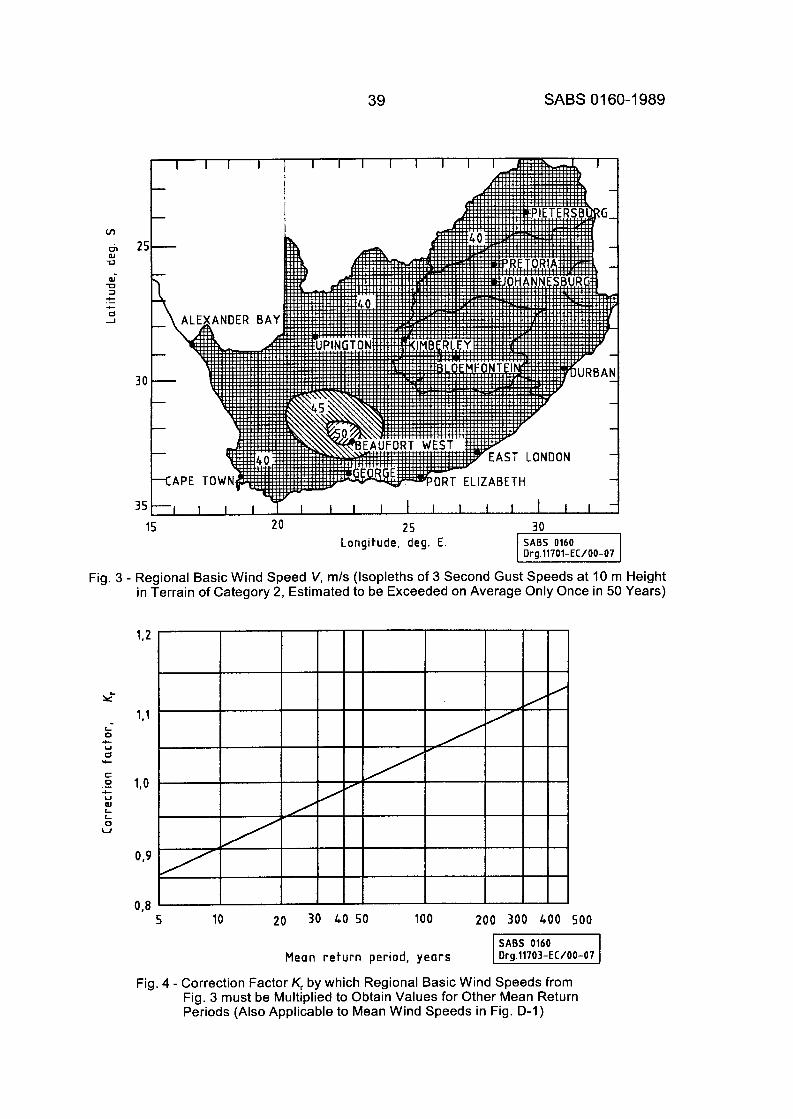
39 SABS 01 60-1 989
m aJ U
Fig. 3 - Regional Basic Wind Speed V, m/s (Isopleths of 3 Second Gust Speeds at 10 IT in Terrain of Category 2, Estimated to be Exceeded on Average Only Once in 5C
L 0 4- U 0 Lc
c 0 .- L U aJ L L 0 U
0.9
O J 5 10 20 30 40 50 100 200 300 400 500
Mean return period, years
Fig. 4 - Correction Factor K, by which Regional Basic Wind Speeds from Fig. 3 must be Multiplied to Obtain Values for Other Mean Return Periods (Also Applicable to Mean Wind Speeds in Fig. D-I)
1 Height 1 Years)
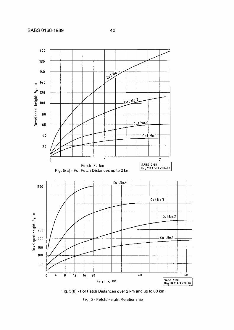
SABS 01 60-1 989 40
180
160
140 E
120
w 60
40
20
I I I I I
0 1 2 Fetch X , krn
Fig. 5(a) - For Fetch Distances up to 2 km
500
E
E
c c
x
'F 250 200
z 150
100
50
f
U
0
(U
D
-
0 Ir 8 12 16 20
Fetch x, k m
40 60
Fig. 5(b) - For Fetch Distances over 2 km and up to 60 km
Fig. 5 - Fetch/Height Relationship
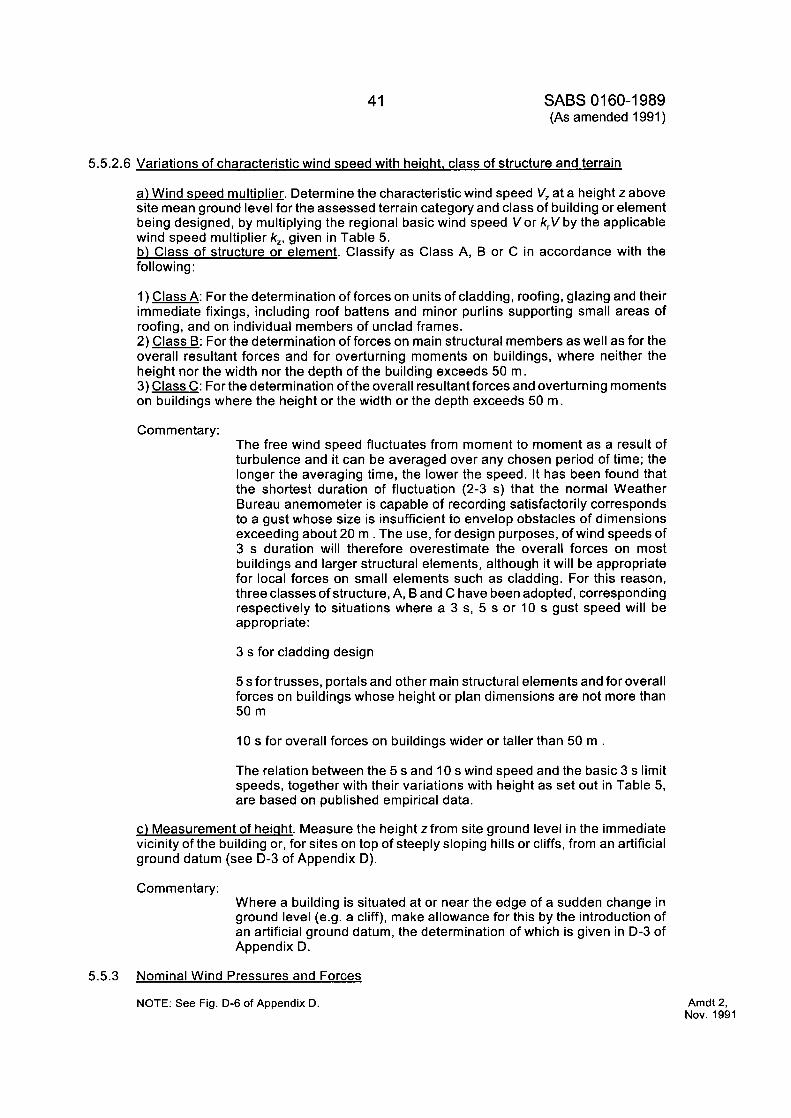
41 SABS 01 60-1 989 (As amended 1991)
5.5.2.6 Variations of characteristic wind speed with heiqht. class of structure and terrain
a) Wind speed multiplier. Determine the characteristic wind speed V, at a height z above site mean ground level for the assessed terrain category and class of building or element being designed, by multiplying the regional basic wind speed Vor k,V by the applicable wind speed multiplier k,, given in Table 5. b) Class of structure or element. Classify as Class A, B or C in accordance with the following:
1) Class A: For the determination of forces on units of cladding, roofing, glazing and their immediate fixings, including roof battens and minor purlins supporting small areas of roofing, and on individual members of unclad frames. 2) Class B: For the determination of forces on main structural members as well as for the overall resultant forces and for overturning moments on buildings, where neither the height nor the width nor the depth of the building exceeds 50 m. 3) Class C: For the determination of the overall resultant forces and overturning moments on buildings where the height or the width or the depth exceeds 50 m.
Commentary: The free wind speed fluctuates from moment to moment as a result of turbulence and it can be averaged over any chosen period of time; the longer the averaging time, the lower the speed. It has been found that the shortest duration of fluctuation (2-3 s) that the normal Weather Bureau anemometer is capable of recording satisfactorily corresponds to a gust whose size is insufficient to envelop obstacles of dimensions exceeding about 20 m . The use, for design purposes, of wind speeds of 3 s duration will therefore overestimate the overall forces on most buildings and larger structural elements, although it will be appropriate for local forces on small elements such as cladding. For this reason, three classes of structure, A, B and C have been adopted, corresponding respectively to situations where a 3 s, 5 s or 10 s gust speed will be appropriate :
3 s for cladding design
5 s for trusses, portals and other main structural elements and for overall forces on buildings whose height or plan dimensions are not more than 50 m
10 s for overall forces on buildings wider or taller than 50 m .
The relation between the 5 s and 10 s wind speed and the basic 3 s limit speeds, together with their variations with height as set out in Table 5, are based on published empirical data.
c) Measurement of heiaht. Measure the height zfrom site ground level in the immediate vicinity of the building or, for sites on top of steeply sloping hills or cliffs, from an artificial ground datum (see D-3 of Appendix D).
Commentary: Where a building is situated at or near the edge of a sudden change in ground level (e.g. a cliff), make allowance for this by the introduction of an artificial ground datum, the determination of which is given in D-3 of Appendix D.
5.5.3 Nominal Wind Pressures and Forces
NOTE: See Fig. D-6 of Appendix D. Amdt 2, Nov. 1991
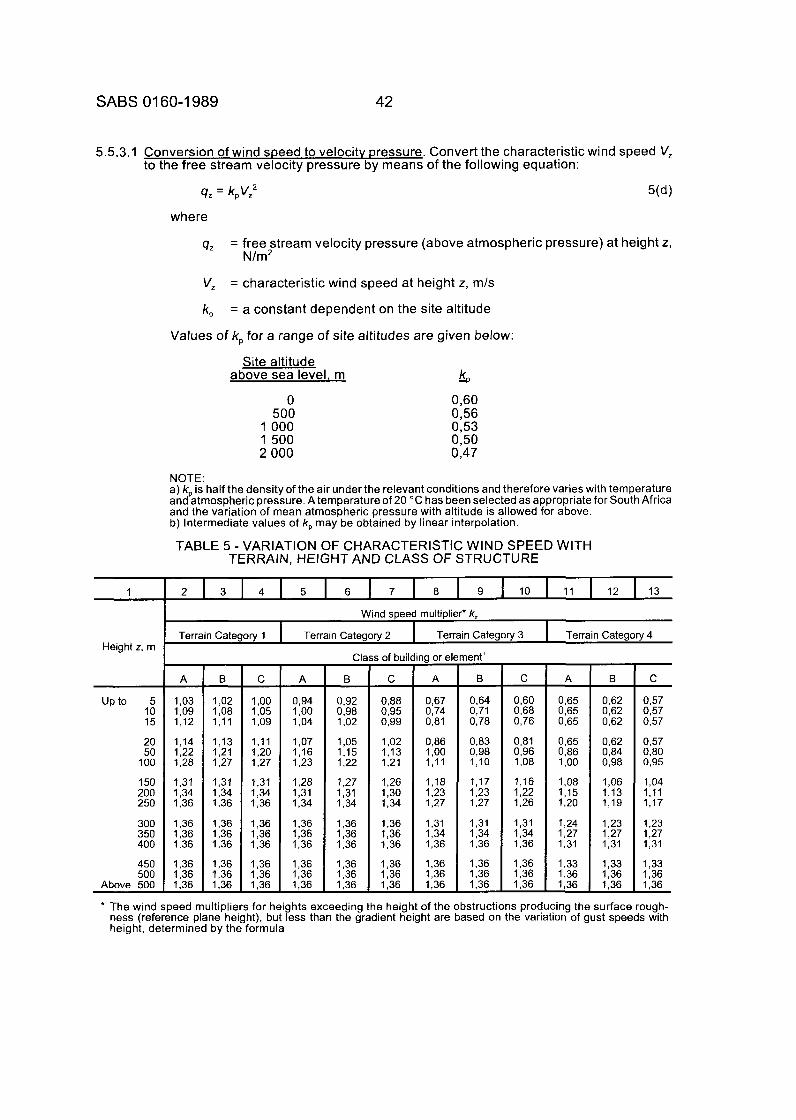
SABS 01 60-1 989 42
1
Height z, rn
5.5.3.1 Conversion of wind speed to velocity pressure. Convert the characteristic wind speed V, to the free stream velocity pressure by means of the following equation:
q z = k,V,2 5(d)
where
q, = free stream velocity pressure (above atmospheric pressure) at height z, N/m2
2 3 4 5 6 7 8 9 10 11 12 13
Wind speed multiplier. k,
Terrain Category 1 Terrain Category 2 Terrain Category 3 Terrain Category 4
V,
k,
= characteristic wind speed at height z, m/s
= a constant dependent on the site altitude
Values of k, for a range of site altitudes are given below:
Site altitude k above sea level, m -P
Up to 5 10 15
20 50
100
150 200 250
300 350 400
0 500
1000 1500 2 000
1,03 1,09 1,12
1,14 1,22 1,28
1,31 1,34 1.36
1,36 1,36 1,36
0,60 0,56 0,53 0,50 0,47
0,94 1,OO 1,04
1,07 1,16 1.23
1,28 1,31 1,34
1,36 1,36 1,36
1,36 1,36 1,36
NOTE: a) kp is half the density of the air under the relevant conditions and therefore varies with temperature and atmospheric pressure. A temperature of 20 " C has been selected as appropriate for South Africa and the variation of mean atmospheric pressure with altitude is allowed for above. b) Intermediate values of k, may be obtained by linear interpolation.
0,92 0,98 1,02
1,05 1,15 1,22
1,27 1,31 1,34
1,36 1,36 1,36
1.36 1,36 1,36
TABLE 5 -VARIATION OF CHARACTERISTIC WIND SPEED WITH TERRAIN, HEIGHT AND CLASS OF STRUCTURE
% I E: Above 500 1,36
- B
1,02 1,08 1,11
1,13 1,21 1,27
1,31 1,34 1,36
1,36 1,36 1,36
1,36 1,36 1,36 -
- C
1 ,oo 1,05 1.09
1,11 1,20 1,27
1,31 1,34 1,36
1,36 1,36 1,36
1,36 1,36 1,36 -
j of building or element'
0,88 0,67 0,64 0,951 0,74 0,71 0,99 0,81 0,78
1,02 0,86 0,83 1,13 1,OO 0,98 1,21 1,11 1,lO
1,26 1,18 1,17 1,30 1 1,23 1 1,23 1,34 1,27 1,27
C A B I
- C
0,57 0,557 0,57
0,57 0,80 0,95
1,04 1.11 1.17
1,23 1,27 1,31
1,33 1,36 1,36
-
- * The wind speed multipliers for heights exceeding the height of the obstructions producing the surface rough- ness (reference plane height), but less than the gradient height are based on the variation of gust speeds with height, determined by the formula
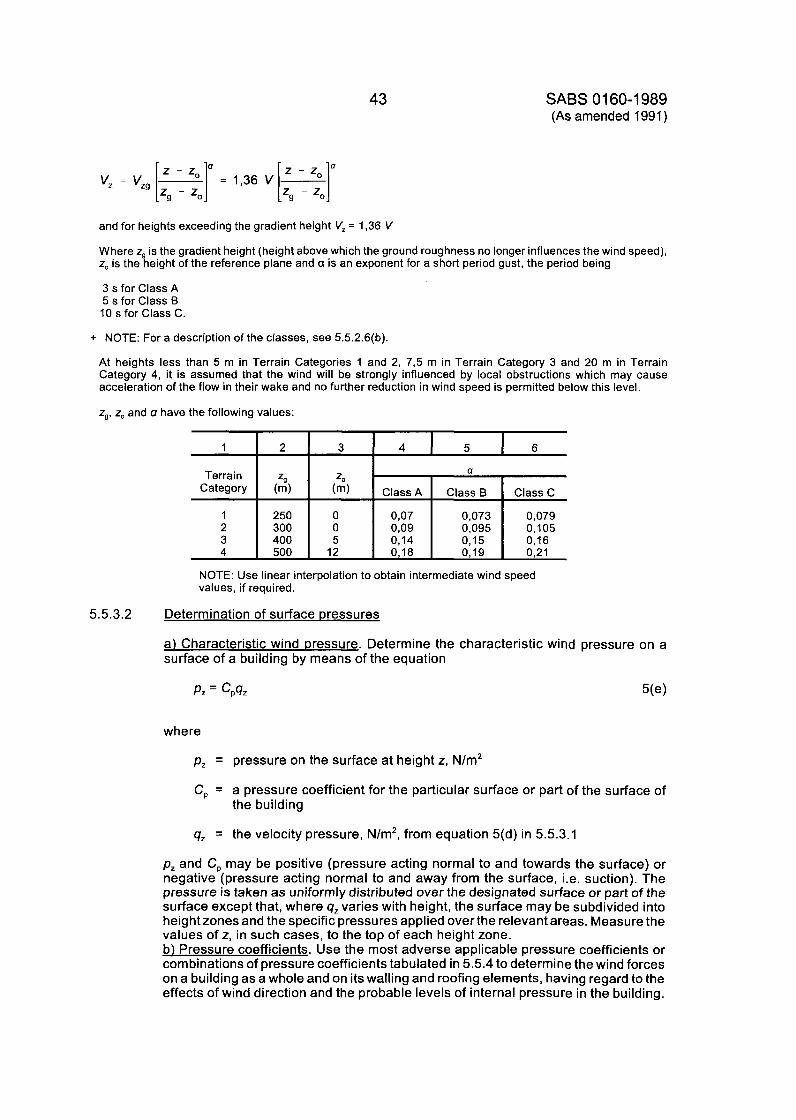
43
1 2
Terrain ZQ Category (rn)
1 250 2 300 3 400 4 500
SABS 01 60-1 989 (As amended 1991)
3 4 I 5 I 6
2, a
(m) C l a s s ~ Class B Classc
0 0,07 0,073 0,079 0 0,09 0,095 0,105 5 0,14 0,15 0,16
12 0,18 0,19 0,21
and for heights exceeding the gradient height V, = 1,36 V
Where zg is the gradient height (height above which the ground roughness no longer influences the wind speed), z, is the height of the reference plane and a is an exponent for a short period gust, the period being
3 s for Class A 5 s for Class B 10 s for Class C.
5.5.3.2 Determination of surface pressures
a) Characteristic wind pressure. Determine the characteristic wind pressure on a surface of a building by means of the equation
P z = c,qz 5(e)
where
p, = pressure on the surface at height z, N/m2
C, = a pressure coefficient for the particular surface or part of the surface of
q, = the velocity pressure, N/m2, from equation 5(d) in 5.5.3.1
the building
p, and C, may be positive (pressure acting normal to and towards the surface) or negative (pressure acting normal to and away from the surface, i.e. suction). The pressure is taken as uniformly distributed over the designated surface or part of the surface except that, where qz varies with height, the surface may be subdivided into height zones and the specific pressures applied over the relevant areas. Measure the values of z, in such cases, to the top of each height zone. b) Pressure coefficients. Use the most adverse applicable pressure coefficients or combinations of pressure coefficients tabulated in 5.5.4 to determine the wind forces on a building as a whole and on its walling and roofing elements, having regard to the effects of wind direction and the probable levels of internal pressure in the building.
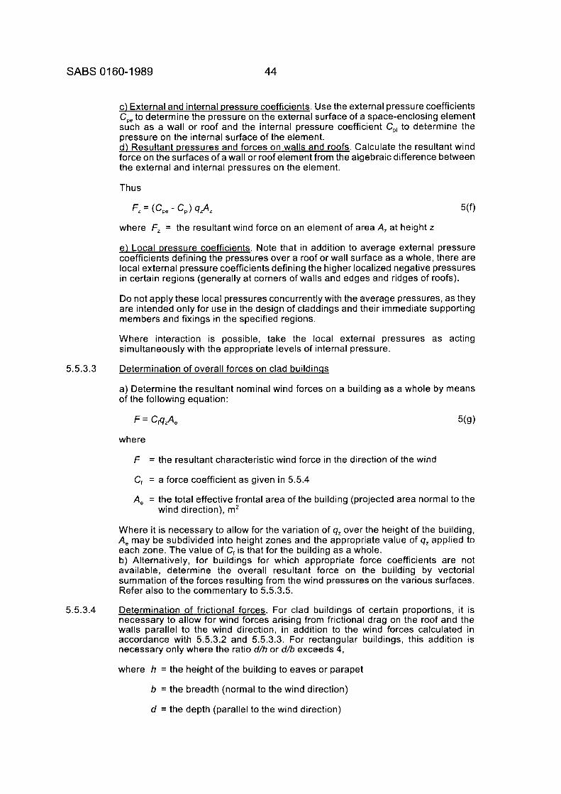
SABS 0160-1 989 44
c) External and internal pressure coefficients. Use the external pressure coefficients Cp, to determine the pressure on the external surface of a space-enclosing element such as a wall or roof and the internal pressure coefficient Cpi to determine the pressure on the internal surface of the element. d) Resultant pressures and forces on walls and roofs. Calculate the resultant wind force on the surfaces of a wall or roof element from the algebraic difference between the external and internal pressures on the element.
Thus
where f, = the resultant wind force on an element of area A, at height z
e) Local pressure coefficients. Note that in addition to average external pressure coefficients defining the pressures over a roof or wall surface as a whole, there are local external pressure coefficients defining the higher localized negative pressures in certain regions (generally at corners of walls and edges and ridges of roofs).
Do not apply these local pressures concurrently with the average pressures, as they are intended only for use in the design of claddings and their immediate supporting members and fixings in the specified regions.
Where interaction is possible, take the local external pressures as acting simultaneously with the appropriate levels of internal pressure.
Determination of overall forces on clad buildinss
a) Determine the resultant nominal wind forces on a building as a whole by means of the following equation:
5.5.3.3
where
f = the resultant characteristic wind force in the direction of the wind
C, = a force coefficient as given in 5.5.4
A, = the total effective frontal area of the building (projected area normal to the wind direction), m2
Where it is necessary to allow for the variation of 9, over the height of the building, A, may be subdivided into height zones and the appropriate value of 9, applied to each zone. The value of C, is that for the building as a whole. b) Alternatively, for buildings for which appropriate force coefficients are not available, determine the overall resultant force on the building by vectorial summation of the forces resulting from the wind pressures on the various surfaces. Refer also to the commentary to 5.5.3.5.
Determination of frictional forces. For clad buildings of certain proportions, it is necessary to allow for wind forces arising from frictional drag on the roof and the walls parallel to the wind direction, in addition to the wind forces calculated in accordance with 5.5.3.2 and 5.5.3.3. For rectangular buildings, this addition is necessary only where the ratio d/h or d/b exceeds 4,
where h = the height of the building to eaves or parapet
b = the breadth (normal to the wind direction)
d = the depth (parallel to the wind direction)
5.5.3.4
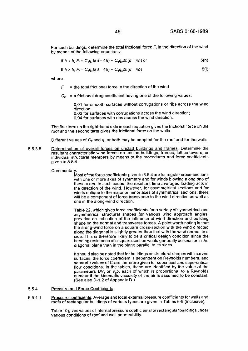
45 SABS 01 60-1 989
For such buildings, determine the total frictional force Ff in the direction of the wind by means of the following equations:
if h s b, Ff = Cf,a,b(d - 4h) + C,q,2h(d - 4h) or
if h > b, Ff = Cf,a,b(d - 4b) + C,q,2h(d - 4b)
5(h)
5(i)
where
Ff = the total frictional force in the direction of the wind
C, = a frictional drag coefficient having one of the following values:
0,Ol for smooth surfaces without corrugations or ribs across the wind direction; 0,02 for surfaces with corrugations across the wind direction; 0,04 for surfaces with ribs across the wind direction.
The first term on the right-hand side in each equation gives the frictional force on the roof and the second term gives the frictional force on the walls.
Different values of C, and q, or both may be adopted for the roof and for the walls.
Determination of overall forces on unclad buildinas and frames. Determine the resultant characteristic wind forces on unclad buildings, frames, lattice towers, or individual structural members by means of the procedures and force coefficients given in 5.5.4.
Com mentary:
5.5.3.5
Most of the force coefficients given in 5.5.4 are for regular cross-sections with one or more axes of symmetry and for winds blowing along one of these axes. In such cases, the resultant time averaged loading acts in the direction of the wind. However, for asymmetrical sections and for winds oblique to the major or minor axes of symmetrical sections, there will be a component of force transverse to the wind direction as well as one in the along-wind direction.
Table 22, which gives force coefficients for a variety of symmetrical and asymmetrical structural shapes for various wind approach angles, provides an indication of the influence of wind direction and building shape on the normal and transverse forces. A point worth noting is that the along-wind force on a square cross-section with the wind directed along the diagonal is slightly greater than that with the wind normal to a side. This is therefore likely to be a critical design condition since the bending resistance of a square section would generally be smaller in the diagonal plane than in the plane parallel to its sides.
It should also be noted that for buildings or structural shapes with curved surfaces, the force coefficient is dependent on Reynolds numbers, and separate values of C, are therefore given for subcritical and supercritical flow conditions. In the tables, these are identified by the value of the parameters DV, or V,b, each of which is proportional to a Reynolds number if the kinematic viscosity of the air is assumed to be constant. (See also D- I .2 of Appendix D.)
5.5.4 Pressure and Force Coefficients
5.5.4.1 Pressure coefficients. Average and local external pressure coefficients for walls and roofs of rectangular buildings of various types are given in Tables 6-9 (inclusive).
Table 10 gives values of internal pressure coefficients for rectangular buildings under various conditions of roof and wall permeability.
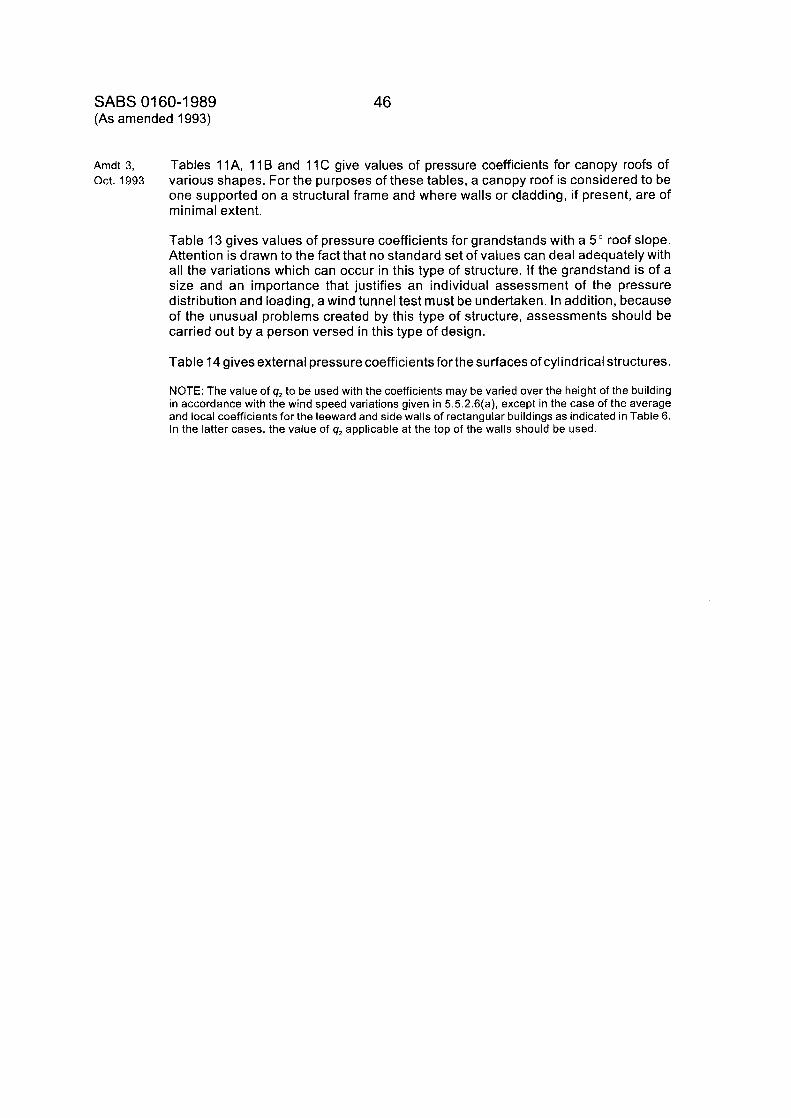
SABS 01 60-1 989 (As amended 1993)
46
Arndt 3, Oct. 1993
Tables 1 IA , 11 B and 11 C give values of pressure coefficients for canopy roofs of various shapes. For the purposes of these tables, a canopy roof is considered to be one supported on a structural frame and where walls or cladding, if present, are of minimal extent.
Table 13 gives values of pressure coefficients for grandstands with a 5 " roof slope. Attention is drawn to the fact that no standard set of values can deal adequately with all the variations which can occur in this type of structure. If the grandstand is of a size and an importance that justifies an individual assessment of the pressure distribution and loading, a wind tunnel test must be undertaken. In addition, because of the unusual problems created by this type of structure, assessments should be carried out by a person versed in this type of design.
Table 14 gives external pressure coefficients for the surfaces of cylindrical structures.
NOTE: The value of q, to be used with the coefficients may be varied over the height of the building in accordance with the wind speed variations given in 5.5.2.6(a), except in the case of the average and local coefficients for the leeward and side walls of rectangular buildings as indicated in Table 6. In the latter cases, the value of g, applicable at the top of the walls should be used.
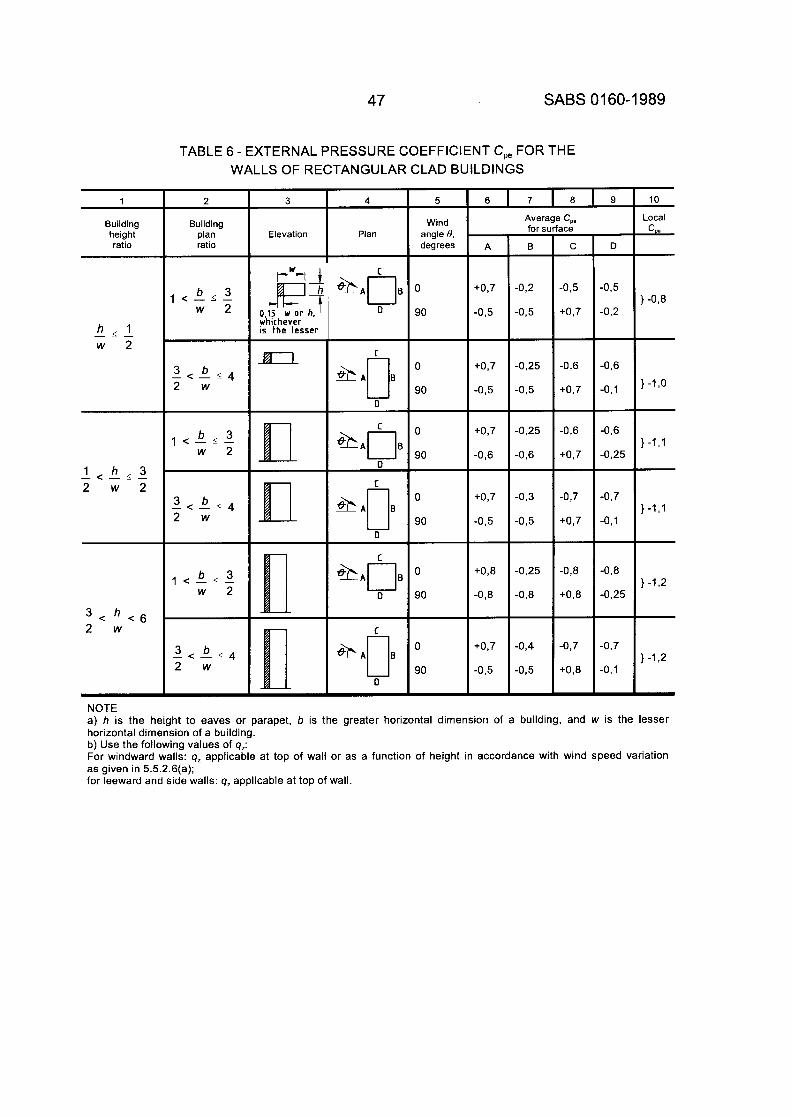
47 SABS 01 60-1 989
NOTE a) h is the height to eaves or parapet, b is the greater horizontal dimension of a building, and w is the lesser horizontal dimension of a building. b) Use the following values of q,: For windward walls: q, applicable at top of wall or as a function of height in accordance with wind speed variation as given in 5.5.2.6(a); for leeward and side walls: q, applicable at top of wall.
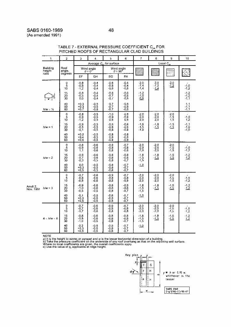
SABS 01 60-1 989 (As amended 1991)
48
TABLE 7 - EXTERNAL PRESSURE COEFFICIENT C,, FOR PITCHED ROOFS OF RECTANGULAR CLAD BUILDINGS
7 8 9 10 3 4 5 6 1 2
3oof ingle, legrees
Average C for surface Loc
R Building height ratio
Win 6 -
EF
igle I"
FH
ngle I"
GH
Win1 0 :
EG
_. .. I......
. ,:, . . . .. '.
-0,8 -0,9 -1,2 -0.8 -0.5 0 8
+0,3 +0,3 +0,7 -0,8 -0,9 -1,2 -0,9 -0,5 -0,l +0,2 +0,4 +0,6
-0,8 -0,9 -1,l -0,9 -0,7 -0,3 0,o
+0,3 +0.5
-
-
- -0,7 -0,8 -0,8 -0,9 -1 ,o -0,5 -0,l +0,3 +0,5 - -0,7 -0,7 -0,7 -0,8 -0,8 -1 ,Q -0,2 +0.3 +0,5 -
-2,o -1,4 -1,4 -1,2 -1 ,o -0-g
-2,0 -U -1 ,o -1,2 -1,2 -1,2 -1,1
-1,1 -1,1 -1.1
-2,o -1,2 -U
-2,o -2,o -2,o -1,8 -U
0 5 10 15 20 30
40 50 60 0 5 10 15 20 30 40 50 60
0 5 10 15 20 30 40 50 60
0 5 10 15 20 30 40 50 60
0 5 10 15 20 30 40 50 60
-
-
-
-0,8 -0,8 -0,8 -0,8
-0,7
-0,7 -0,7 -0,7
-1 ,o -0,9 -0,8 -0,8 -0,8 -0.8 -0,8 -0,8 -0,8 -0,9 -0,8 -0,8 -0,8 -0,8 -0,8 -0,a -0,8 -0,8 -0,9 -0,8 -0,8 -0,8
-0,8 -0,8 -0,8 -0,8 -0,9 -0,8 -0,8
-0,7
-
-0,8
-
-0,8 -0,8 -0,8 -0,8 -0,8 -0.8 -
-0,4 -0,4 -0,6 -0,6
-0,6
-0,6 -0,6 -0,6
-0,6
-0,6 -0,6 -0,6 -0,8
-0.6
-0,6
-0,8
-0,8 -0,8 - -0,7 -0,8 -0,8 -0,8 -0,8 -0,7 -0,7 -0.7 -0.7 -0,7 -0,8 -0,8 -0,8
-0,7 -0,7
-0,7
-0,7 -0.8
-0,8
-0,7
-0,8 -0,8 -0,8 -0,7 -0,7 -0,7 -0,7
-0,4 -0,4 -0,4 -0,4 -0,4 -0,4
-0,5 -0,5 -0,6
-0,5 -0,5 -0,5 -0,5 -0,5 -0.5 -0,5 -0,5 -0.5 -0,6 -0,6 -0,6 -0,6 -0,6 -0,5 -0,5 -0,5 -0,5 -0,6 -0,6 -0,6
-0,6 -0,6 -0,5 -0,5
-0,5 -0,6 -0,6
-0.5 - -0,6
-0,6 -0,6 -0,5 -0,5 -0,5 -0,5 -
h/w s ?4
h/w = 1
-2,o -2,o -2,o -1,8 -1,s -l,o
-1 ,o -1,2 -1,1 -1 ,o -1 ,o
-2,0 -13 -1,5 -1,5 -U
- -2,0 -1,5 -1,5 -1,5 -2
-2,0 -1,5 -1,5 -1,5 -G
-2,0 -1,5 -1,5 -1,5 -U
-2,o -2,o -2,o -1,8 -U
-1 ,o -1,2 -1,2 -U
-2,o -2,o -2,o -1,8 -1,5 -1,5 -U
-2,o -2,o -2,o -1,8 -1,5 -1,5 -U
-2,o -2,o -2,o -1,8 -1,5 -1,5 -U
h/w = 2
-2,o -2,o -2,o -1,8 -U
-1,5 -1,2 -1,2 -2 Amdt 2,
Nov. 1991 h/w =
-2,o -2,o -2,o -1,8 -U
-1 ,o -1,2 -1,2 -2 4 I h/w I 6
NOTE a h is the height to eaves or parapet and w is the lesser horizontal dimension of a building. b j Take the pressure coefficient on the underside of any roof overhang as that on the adjoining wall surface. Where no local coefficients are given, the overall coefficients apply. c) Use the value of q, applicable at ridge height.
y h o r 0.15 w, whichever is the lesse r
SABS 0160 1 Ora 12165-EC/00-07
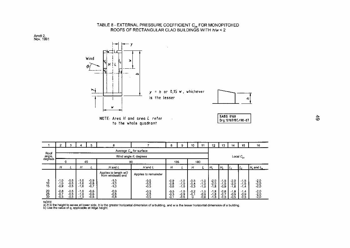
TABLE 8 - EXTERNAL PRESSURE COEFFICIENT C,, FOR MONOPITCHED ROOFS OF RECTANGULAR CLAD BUILDINGS WITH h/w e 2
Amdt 2, Nov. 1991
Wind
__
“1 y = h or 0,15 w , whichever b--7 is the l esser
NOTE: A r e a H and area L r e f e r t o the whole quadrant
20 -0,8 -05 -1,0 -0,6 -0,9 -0,5 -0,5 -1,0 -0,2 -1,0 - l ,8 -0,8 -1,8 -1,4 -2,O 25 -0,7 -0,5 -1 0 -0,6 -0,8 -0,5 -0,3 -0,9 -061 -0,9 -1,8 -0,7 -0,9 -0 9 -2 0 30 -05 -0,5 -1:O -0,6 -0,8 -0,5 -0,l -0,6 -0,6 -1,8 -0,5 -0,5 -0:5 -210
P CO
NOTE a h is the hei ht to eaves at lower side, b is the greater horizontal dimension of a building, and w is the lesser horizontal dimension of a building. b{ Use the “ a t e of g, applicable at ridge height.
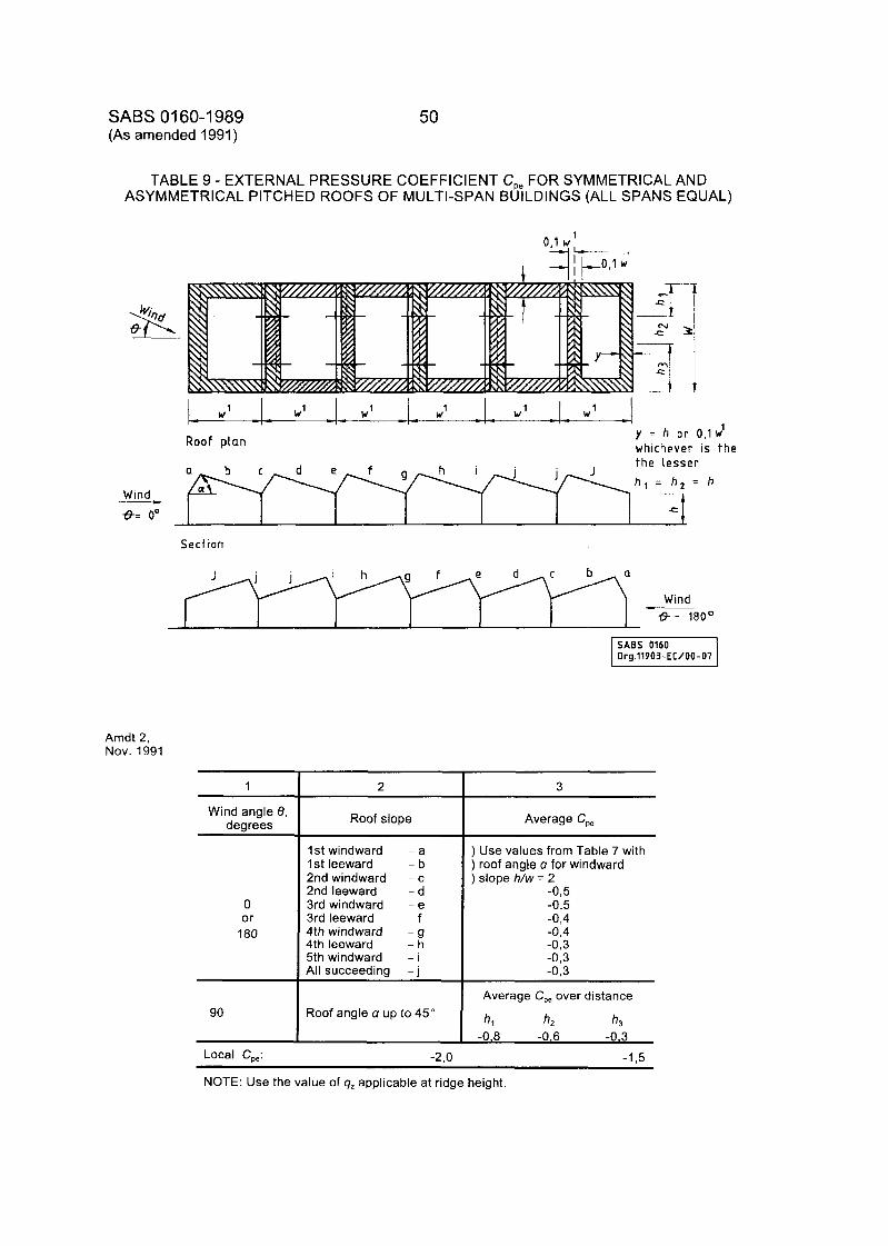
SABS 01 60-1 989 (As amended 1991 )
50
TABLE 9 - EXTERNAL PRESSURE COEFFICIENT C,, FOR SYMMETRICAL AND ASYMMETRICAL PITCHED ROOFS OF MULTI-SPAN BUILDINGS (ALL SPANS EQUAL)
w’ _I_ W ’ W 1 W 1 I w’ _ _ 1 y = h or 0,l w
whichever is t h e Roof plan
Wind ___)
the Lesser
h l = h , = h
-I=
Section
Wind c__
ff- 180°
SABS 0160 1 Drg.11903-EC/00-07
Amdt 2, Nov. 1991
1
Wind angle 8, degrees
0 or
180
90
2
Roof slope
1st windward 1st leeward 2nd windward 2nd leeward 3rd windward 3rd leeward 4th windward 4th leeward 5th windward All succeeding
- a - b - c - d - e - f - 9 - h - i - j
Roof angle a up to 45”
Local CO*: -2 0
3
Average C,,
) Use values from Table 7 with ) roof angle a for windward ) slope h/w = 2
-0,5 -0,5 -0,4 -0,4 -0,3 -0,3 -0,3
Average C,, over distance
h, h2 h3
-0.8 -0.6 -0.3 -1,5
NOTE: Use the value of 9, applicable at ridge height.
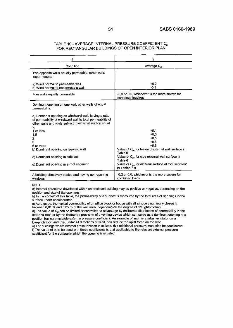
51 SABS 01 60-1 989
TABLE 10 - AVERAGE INTERNAL PRESSURE COEFFICIENT C,i FOR RECTANGULAR BUILDINGS OF OPEN INTERIOR PLAN
1
Condition
Two opposite walls equally permeable, other walls impermeable:
a) Wind normal to permeable wall b) Wind normal to impermeable wall
Four walls equally permeable
Dominant opening on one wall, other walls of equal permeability:
a) Dominant opening on windward wall, having a ratio of permeability of windward wall to total permeability of other walls and roofs subject to external suction equal to 1 or less 1 3 2 3 6 or more b) Dominant opening on leeward wall
c) Dominant opening in side wall
d) Dominant opening in a roof segment
A building effectively sealed and having non-opening windows
NOTE
Average CDi
+0,2
-0,3 or O,O, whichever is the more severe for combined loadings
+0,1 +0,3 +0,5 +0,6 +0,8
Value of C, for leeward external wall surface in Table 6 Value of C, for side external wall surface in Table 6 Value of C, for external surface of roof segment in Tables 7-9
-0,2 or O,O, whichever is the more severe for combined loads
a) Internal pressures developed within an enclosed building may be positive or negative, depending on the position and size of the openings. b) In the context of this table, the permeability of a surface is measured by the total area of openings in the surface under consideration. c) As a guide, the typical permeability of an office block or house with all windows nominally closed is between 0,Ol % and 0,05 % of the wall area, depending on the degree of draughtproofing. d) The value of Cpi can be limited or controlled to advantage by deliberate distribution of permeability in the wall and roof, or by the deliberate provision of a venting device which can serve as a dominant opening at a position having a suitable external pressure coefficient. An example of such is a ridge ventilator on a low-pitch roof, and this, under all directions of wind, can reduce the uplift force on the roof. e) For buildings where internal pressurization is utilized, this additional pressure must also be considered. f) The value of q, to be used with these coefficients is that applicable to the relevant external pressure coefficient for the surface in which the opening is situated.
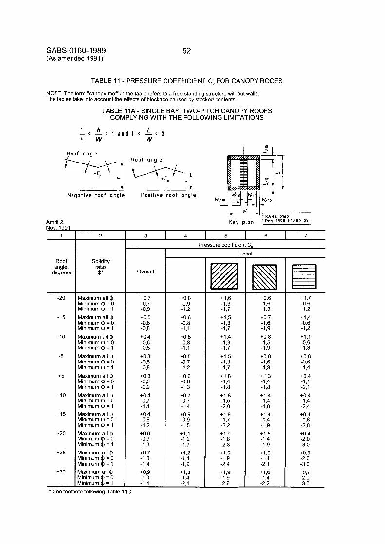
SABS 01 60-1 989 (As amended 1991 )
Amdt 2, Nov. 1991
1
Roof angle,
degrees
-20
-15
-10
-5
+5
+I0
+I5
+20
+25
+30
52
2
Solidity ratio @*
Maximum all @ Minimum = O Minimum $ = 1 Maximum all @ Minimum = 0 Minimum 8 = 1 Maximum all @ Minimum = O Minimum 8 = 1 Maximum all @ Minimum = O Minimum $ = 1 Maximum all @ Minimum = O Minimum = 1 Maximum all @ Minimum = O Minimum $ = 1 Maximum all @ Minimum = O Minimum 8 = 1 Maximum all @ Minimum = O Minimum $ = 1 Maximum all @ Minimum = O Minimum $ = 1 Maximum all @ Minimum = O Minimum $ = 1
TABLE 11 - PRESSURE COEFFICIENT C, FOR CANOPY ROOFS
Overall
-1,4
NOTE: The term "canopy root" in the table refers to a free-standing structure without walls. The tables take into account the effects of blockage caused by stacked contents.
-2,l
TABLE 11A - SINGLE BAY, TWO-PITCH CANOPY ROOFS COMPLYING WITH THE FOLLOWING LIMITATIONS
1 h L - - < - - < 1 a n d 1 -< - - < 3 4 w W 0
R o o f angle I 31.-
51
R o o f angle
Negative roof angle Positive r o o f angle
3 I 4 I 5 I 6 I 7 Pressure coefficient C-
+0,7 -0,7 -0,9 +0,5 -0,6 -0,8 +0,4 -0,6 -0,8
+0,3 -0,5 -0.8 +0,3 -0,6 -0,9 +0,4 -0,7 -1 ,I +0,4 -0,8 -1,2 +0,6 -0,9 -1,3 +0,7 -1 ,o -1,4 +0,9 -1 ,o
I
+0,8 -0,9 -1,2 +0,6 -0,8 -1 ,I +0,6 -0,8 -1 , I +0,5 -0,7 -1,2 +0,6 -0,6 -1,3 +0,7 -0,7 -1,4 +0,9 -0,9 -1,5 +1,1 -1,2 -1,7 +I ,2 -1,4 -1,9 + I ,3 -1,4
L
+I ,6 -1,3 -1,7 +1,5 -1,3 -1,7 +I ,4 -1,3 -1,7 +I ,5 -1,3 -1,7 +1,8 -1,4 -1,8 + I ,8 -1,5 -2,o +1,9 -1,7 -2,2 + I ,9 -1,8 -2,3 + I ,9 -1,9 -2,4 + I ,9 -1,9 -2,6
al
+0,6 -1,6 -1,9 +0,7 -1,6 -1,9 +0,8 -1,5 -1,9 +0,8 -1,6 -1,9 +I ,3 -1.4 -1,8 + I ,4 -1,4 -1,8 +I ,4 -1,4 -1,9 + I ,5 -1,4 -1,9 +I ,6 -1,4 -2.1 + I ,6 -1,4 -2,2
+I ,7 -0,6 -1,2 +I ,4 -0,6 -1,2 +I , I -0,6 -1,3 +0,8 -0,6 -1,4 +0,4 -1 , I -2,l +0,4 -1,4 -2,4 +0,4 -1,8 -2,8 +0,4 -2,o -3,O +0,5 -2,o -3,O +0,7 -2,o -3,O
* See footnote following Table 1 1 C.
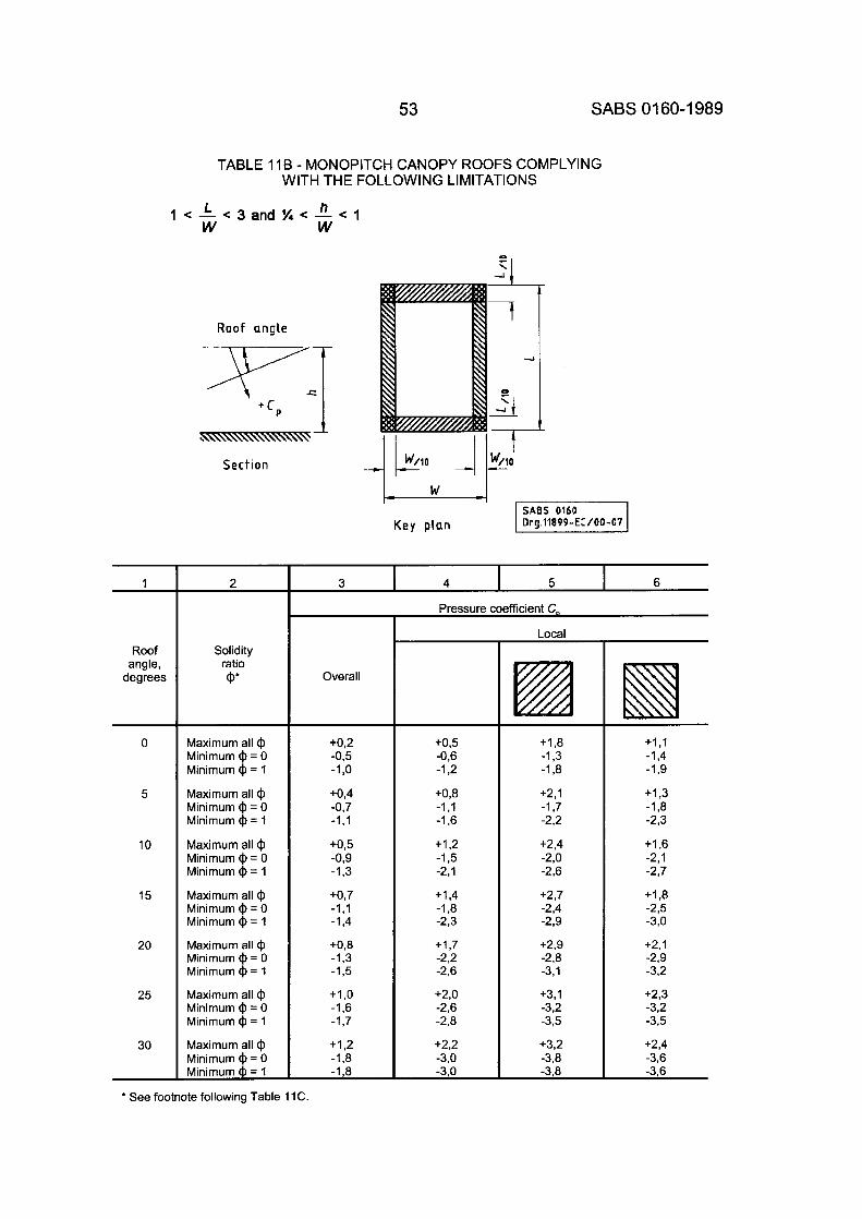
53 SABS 01 60-1 989
Solidity ratio (P
Maximum all @
Minimum ($ = 1 Minimum @ = 0
Maximum all @ Minimum @ = 0 Minimum @ = 1
Minimum @ = 0 Maximum all @
Minimum @ = 1
Maximum all @ Minimum @ = 0
Maximum all @
Minimum @ = 1
Minimum @ = 0 Minimum @ = 1
Maximum all @ Minimum @ = 0 Minimum @ = 1
Maximum all ($ Minimum @ = 0 Minimum @ = 1
TABLE 11 B - MONOPITCH CANOPY ROOFS COMPLYING WITH THE FOLLOWING LIMITATIONS
Overall
+0,2 -0,5 -1 ,o +0,4 -0,7 -1,l
+0,5 -0,9 -1.3
+0,7 -1,l -1,4
+0,8 -1,3 -1,5
+I ,o -1,6 -1,7
+I ,2 -1 ,a -1 ,a
L n 1 < - < 3 a n d % < - < l W W
Roof angle
Sect ion c W/lO -1 t
W/lO c
SABS 0160 K e y plan 1 Org.11899-EC/00-07
1
Roof angle,
degrees
0
5
10
15
20
25
30
* See foo
Pressure
+0,5 -0,6 -1,2
+O,B -1 ,I -1,6
+1,2 -1,5 -2,l
+1,4 -1 ,a -2,3
+ I ,7 -2,2 -2,6
+2,0 -2,6 -2,8
+2,2 -3,O -3,O
5 1 6
iefficient C,
Local
+I ,8 -1,3 -1 ,a +2,1 -1,7 -2.2
+2,4 -2,o -2,6
+2,7 -2,4 -2,9
+2,9 -2,8 -3,l
+3,1 -3,2 -3,5
+3,2 -3,B -3,8
-1,9
+I ,3 -1,B -2,3
+I ,6 -2,1 -2,7
+I ,a -2,5 -3,0
+2,1 -2,9 -3,2
+2,3 -3,2 -3.5
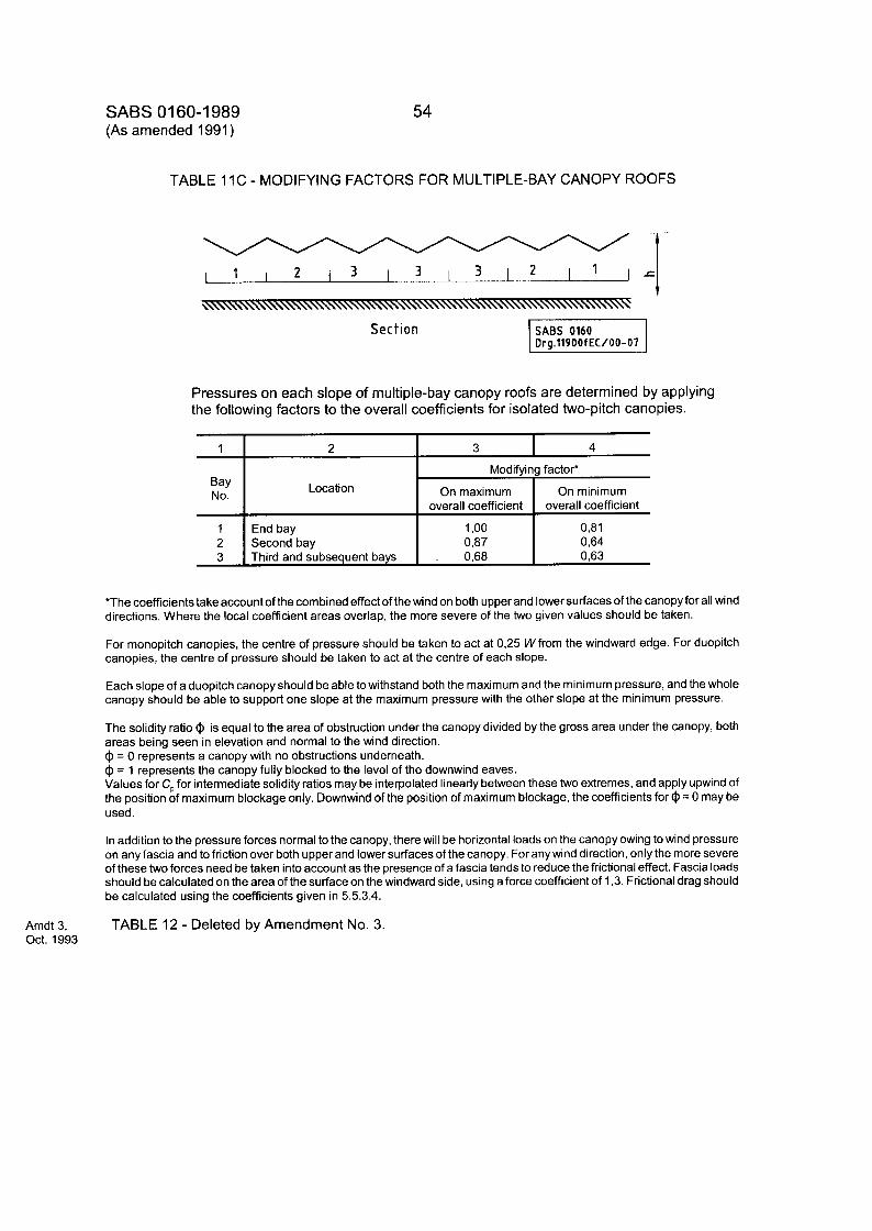
SABS 01 60-1 989 (As amended 1991 )
Location
End bay Second bay Third and subsequent bays
54
Modifying factor*
On maximum On minimum overall coefficient overall coefficient
1 ,oo 0,81 0,87 0,64
. 0,68 0,63
TABLE 11C - MODIFYING FACTORS FOR MULTIPLE-BAY CANOPY ROOFS
Pressures on each slope of multiple-bay canopy roofs are determined by applying the following factors to the overall coefficients for isolated two-pitch canopies. -
1
Bay No.
1 2 3
7 I 3 I 4
*The Coefficients take account of the combined effect of the wind on both upper and lower surfaces of the canopy for all wind directions. Where the local coefficient areas overlap, the more severe of the two given values should be taken.
For monopitch canopies, the centre of pressure should be taken to act at 0,25 Wfrom the windward edge. For duopitch canopies, the centre of pressure should be taken to act at the centre of each slope.
Each slope of a duopitch canopy should be able towithstand both the maximum and the minimum pressure, and the whole canopy should be able to support one slope at the maximum pressure with the other slope at the minimum pressure.
The solidity ratio @ is equal to the area of obstruction under the canopy divided by the gross area under the canopy, both areas being seen in elevation and normal to the wind direction. @ = 0 represents a canopy with no obstructions underneath. @ = 1 represents the canopy fully blocked to the level of the downwind eaves. Values for C, for intermediate solidity ratios may be interpolated linearly between these two extremes, and apply upwind of the position of maximum blockage only. Downwind of the position of maximum blockage, the coefficients for @ = 0 may be used.
In addition to the pressure forces normal to the canopy, there will be horizontal loads on the canopy owing to wind pressure on any fascia and to friction over both upper and lower surfaces of the canopy. For any wind direction, only the more severe of these two forces need be taken into account as the presence of a fascia tends to reduce the frictional effect. Fascia loads should be calculated on the area of the surface on the windward side, using a force coefficient of 1,3. Frictional drag should be calculated using the coefficients given in 5.5.3.4.
TABLE 12 - Deleted by Amendment No. 3. Amdt 3, Oct. 1993
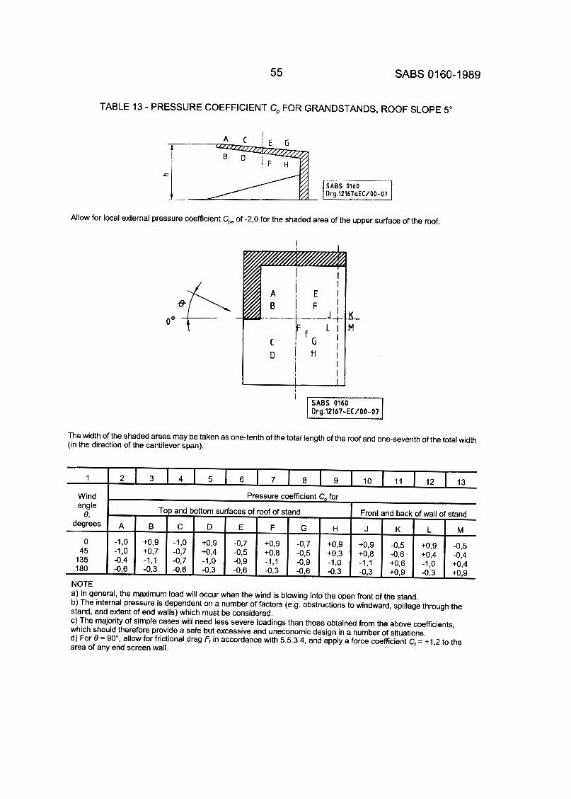
55 SABS 01 60-1 989
angle
degrees e,
0 45
135 180
TABLE 13 - PRESSURE COEFFICIENT C, FOR GRANDSTANDS, ROOF SLOPE 5"
Top and bottom surfaces of roof of stand Front and back of wall of stand
A B C D E F G H J K L M -1,O +O,9 -1,O +O,9 -0,7 +0,9 -0,7 +0,9 +0,9 -0.5 +0,9 -0,s -1,O +0,7 -0,7 +0,4 -0,5 +0,8 -0,5 +0,3 +0,8 -0,6 +0,4 -0,4 -0,6 -0.3 -0,6 -0,3 -0,6 -0,3 -0,6 -0,3 -0,3 +0,9 -0,3 +O,g -0,4 -1,l -0,7 -1,0 -0,9 -1,l -0,9 -1,0 -1,l +0,6 -1,o +0,4
Allow for local external pressure coefficient C,, of -2,O for the shaded area of the upper surface of the roof.
O0 t K M -
The width of the shaded areas may be taken as one-tenth of the total length of the roof and one-seventh of the total width (in the direction of the cantilever span).
3 4 6 7 8 9 10 11 12 13
Pressure coefficient C, for Wind
NOTE a) In general, the maximum load will occur when the wind is blowing into the open front of the stand. b) The internal pressure is dependent on a number of factors (e.g. obstructions to windward, spillage through the stand, and extent of end walls) which must be considered. c) The majority of simple cases will need less severe loadings than those obtained from the above coefficients, which should therefore provide a safe but excessive and uneconomic design in a number of situations. d) For 8 = go", allow for frictional drag Ff in accordance with 5.5.3.4, and apply a force coefficient C, = + I ,2 to the area of any end screen wall.
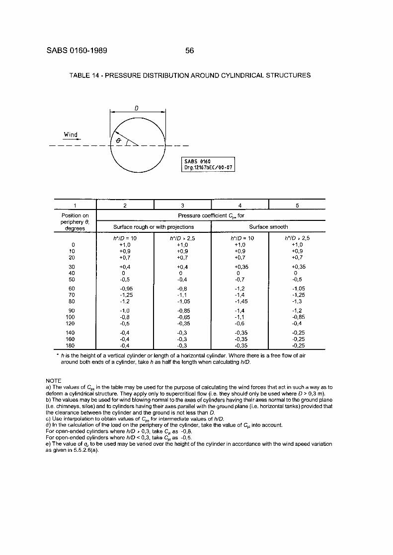
SABS 01 60-1 989 56
TABLE 14 - PRESSURE DISTRIBUTION AROUND CYLINDRICAL STRUCTURES
1
Position on periphery 8,
degrees
0 10 20 30 40 50 60 70 80 90 100 120 140 160 180
2 I 3 I 4 1 5 Pressure coefficient CO, for
Surface rough or with projections
h*ID = 10 +1,0 +0,9 +0,7
+0,4 0
-0,5
-0.95 -1,25 -1,2 -l,o -0,8 -0,5 -0,4 -0,4 -0,4
h*lD 1. 2,5 +I ,o +0,9 +0,7
+0,4 0 -0,4 -0,8 -1,l -1,05 -0,85 -0,65 -0,35 -0,3 -0.3 -0.3
Surface smooth
h*ID = 10 +I ,o +0,9 +0,7
+0,35 0
-0,7
-1,2 -1,4 -1,45 -1,4 -1,l -0,6 -0,35 -0,35 -0.35
h*lD 2 2,5 +1,0 +0,9 +0,7
+0,35 0 -0,5 -1,05 -1,25 -1,3 -1,2 -0,85 -0,4 -0,251 -0,25 -0,25
* h is the height of a vertical cylinder or length of a horizontal cylinder. Where there is a free flow of air around both ends of a cylinder, take h as half the length when calculating h/D.
NOTE a) The values of C,, in the table may be used for the purpose of calculating the wind forces that act in such a way as to deform a cylindrical structure. They apply only to supercritical flow (i.e. they should only be used where D > 0,3 m). b) The values may be used for wind blowing normal to the axes of cylinders having their axes normal to the ground plane (i.e. chimneys, silos) and to cylinders having their axes parallel with the ground plane (i.e. horizontal tanks) provided that the clearance between the cylinder and the ground is not less than D. c) Use interpolation to obtain values of C, for intermediate values of h/D. d) In the calculation of the load on the periphery of the cylinder, take the value of C,, into account. For open-ended cylinders where h/D 1. 0,3, take C,, as -0,8. For open-ended cylinders where h/D < 0,3, take C,, as -0,5. e) The value of q, to be used may be varied over the height of the cylinder in accordance with the wind speed variation as given in 5.5.2.6(a).
57 SABS 01 60-1 989
5.5.4.2 Force coefficients
a) Clad buildinas, free-standina walls, hoardinas and similar structures. Force coefficients for determining the overall resultant along-wind force in accordance with 5.5.3.3 are given in Fig. 6 for rectangular clad buildings, in Table 15 for clad buildings of uniform sections as shown, and in Table 16 for low walls or hoardings on or above the ground. In general, the value of 9, may be varied over the height of the building.
b) Unclad buildinas, frames, screens and lattice structures
1) Sinale frames. Calculate the resultant wind force on a single frame for the case where the wind direction is normal to the plane of the frame unless it can be shown that another wind angle is more appropriate. Determine the force by means of equation 5(g) in 5.5.3.3 but take A, as the net (i.e. solid) projected area, excluding the openings between members.
The relevant force coefficients are given in Table 17 for a single frame consisting of
i) members of flat-sided cross-section, or ii) members of circular cross-section,
in which all the members of the frame have DV, values less than 6 m2/s or all members have DV, values equal to or exceeding 6 m2/s.
When single frames are composed of members of circular cross-section, it is possible that the smaller members will be in the subcritical flow range (i.e. DV, < 6 m’/s) and the larger members will be in the supercritical flow range (i.e. DV, ~ 6 m2/s), and there may also be some details fabricated from flat-sided sections.
In this situation, the wind force acting on the composite frame should be calculated by using an effective force coefficient equal to:
- - Area of the frame in a supercritical flow where Z A,
Ae = the total effective frontal area of the frame (i.e. the net solid area)
= the force coefficient of the supercritical range for circular sections from Table 17 cf (S U P)
= the force coefficient of the subcritical range for circular sections from Table 17 cf(Sub)
= the force coefficient of the flat-sided sections from Table 22
= the effective area of the subcritical circular sections
= the effective area of the flat-sided sections
cf(Flat)
A(Circ. sub)
A (Flat) -
A (Sub) - A(Circ. sub) + A(Flat)
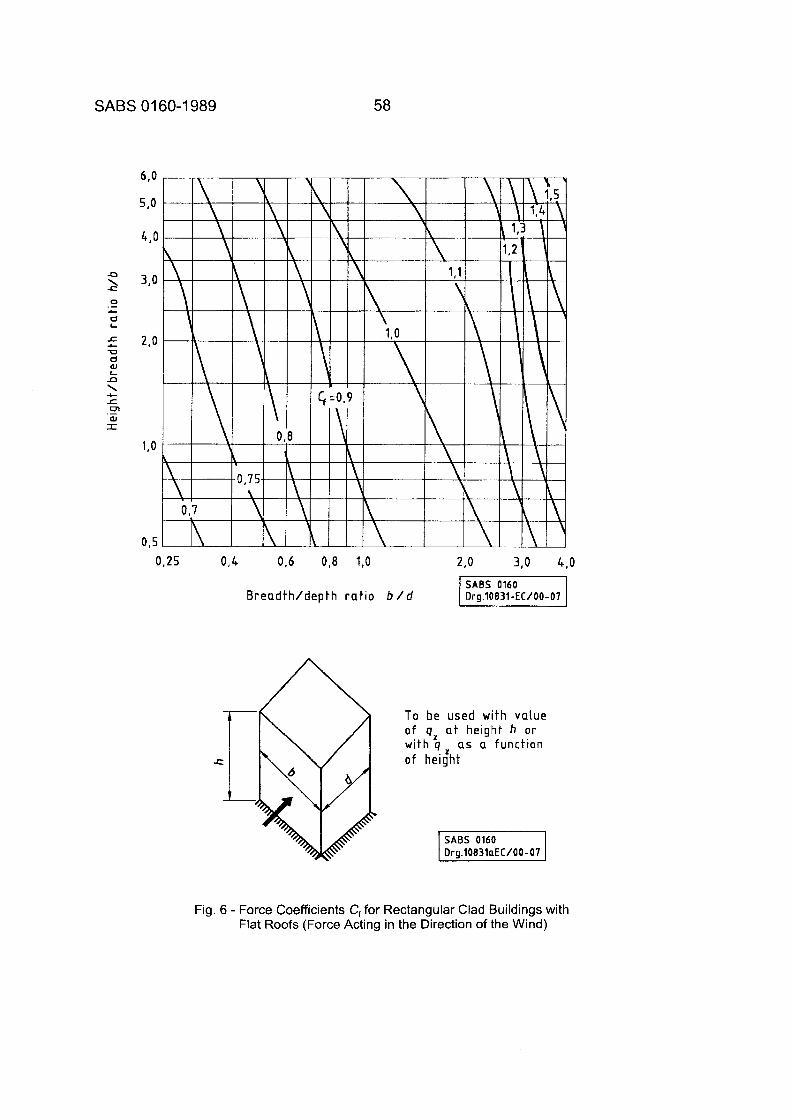
SABS 01 60-1 989
-a \ -E:
0 -I- d L
r U d 01 L
.-
c
n \ L: m aJ I
c
._
58
0,25 0,4 0,6 0,8 1,0 2,o 3,O 4,O
SABS 0160 Breadth/depth ratio b / d 71 Org.10831-EC/00-07
To be used wi th value o f 9, at height h o r with q as a function o f height
Fig. 6 - Force Coefficients C, for Rectangular Clad Buildings with Flat Roofs (Force Acting in the Direction of the Wind)
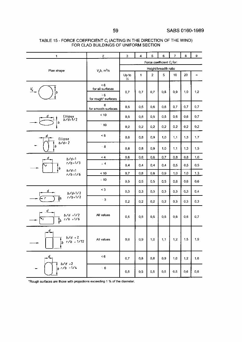
59 SABS 01 60-1 989
tio
10
0,9
0,7
0,6
0,2
1,l
1,l
0,8
0,5
l , o
0.6
0,3
0,3
0,6
1,2
l , o
0,5
TABLE 15 - FORCE COEFFICIENT C, (ACTING IN THE DIRECTION OF THE WIND) FOR CLAD BUILDINGS OF UNIFORM SECTION
20
l ,o
0,7
0,6
0,2
1,3
1,3
0,8
0,5
l , o
0,6
0,3
0,3
0,6
1,5
1,2
0,6
1
0,7
3 4 5 6 7 8 9
Force coefficient C, for:
0,8
2
V,b, m2/s eig hff breadtt I Plan shape
up to Y7 -
1 - 215
~6 for all surfaces
for rough' surtaces
for smooth surfaces
< 10
6
6
0.7
Ellipse
- Qb b / d = 1 / 2 - 10
- 8
< 4 b / d = l r / b =1/3
- rj16 b / d = l r / b = 1 / 6
- 4
< 10
10
< 3
- 3
d - All values
All values
c 6 0.7
6
*Rough surfaces are those with projections exceeding 1 % of the diameter.
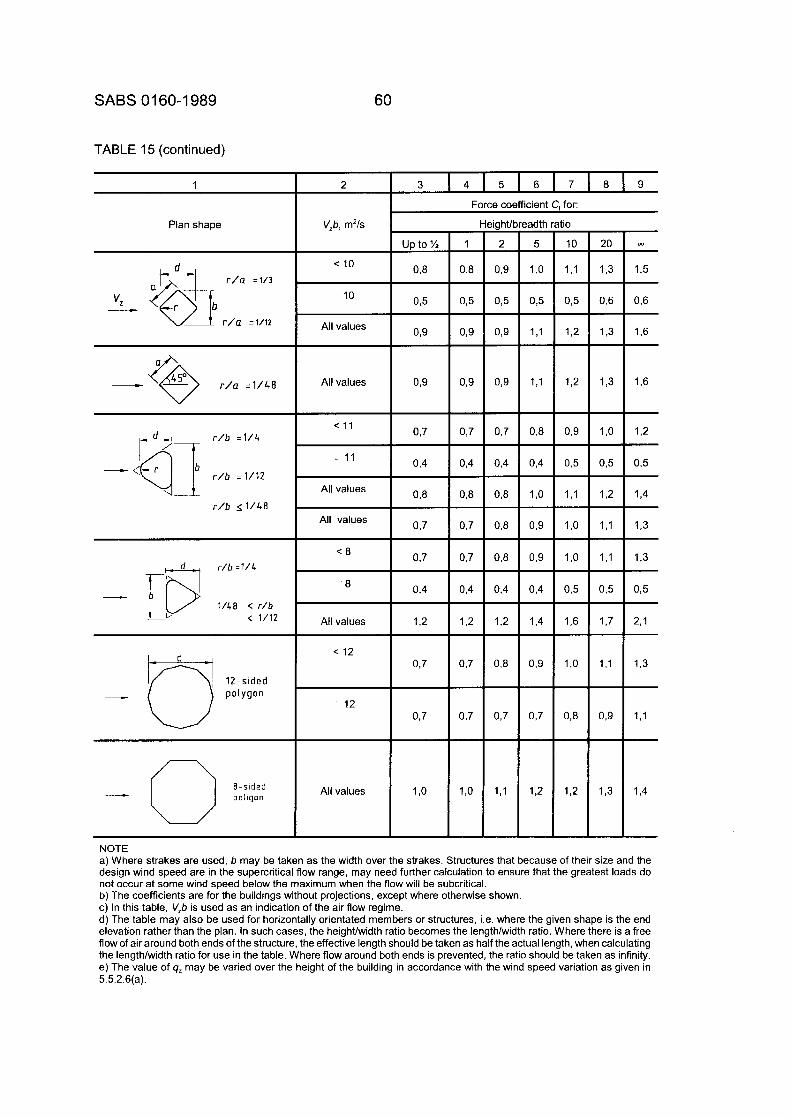
SABS 01 60-1 989 60
TABLE 15 (continued)
1 2 3 4 5 6 7 8 9
Force coefficient C+ for:
Plan shape V,b, m2/s Height
1 2
0,8 0,9
0,5 0,5
0,9 0,9
0,9 0,9
0,7 0,7
0,4 0,4
0,8 0,8
0,7 0,8
0,7 0,8
0,4 0,4
1,2 1,2
0,7 0,8
0,7 0,7
l,o 1,l
?adth ratio
5 10
l,o 1,l
0,5 0,5
1,l 1,2
1,l 1,2
0,8 0,9
0,4 0,5
l,o 1,l
0,9 1.0
0,9 l,o
0,4 0,5
1.4 1,6
0,9 l,o
0,7 0,8
1,2 1,2
- m u p to %
0 8 c 10
10
All values
- r / a =1/48 All values
c 1 1 r / b =1/4
r / b = 1 / 1 2
1 1
All values
r / b < I 1 4 0 All values
r / b : 1 / 4
1 / 4 0 < r / b < 1/12
-- 8
All values
c 12 0.7
12
1 ,o All values
NOTE a) Where strakes are used, b may be taken as the width over the strakes. Structures that because of their size and the design wind speed are in the supercritical flow range, may need further calculation to ensure that the greatest loads do not occur at some wind speed below the maximum when the flow will be subcritical. b) The coefficients are for the buildings without projections, except where otherwise shown. c) In this table, V,b is used as an indication of the air flow regime. d) The table may also be used for horizontally orientated members or structures, i.e. where the given shape is the end elevation rather than the plan. In such cases, the heighvwidth ratio becomes the length/width ratio. Where there is a free flow of air around both ends of the structure, the effective length should be taken as half the actual length, when calculating the lenath/width ratio for use in the table. Where flow around both ends is orevented. the ratio should be taken as infinitv. e) Theialue of q, may be varied over the height of the building in accordance with.the wind speed variation as given in 5.5.2.6(a).
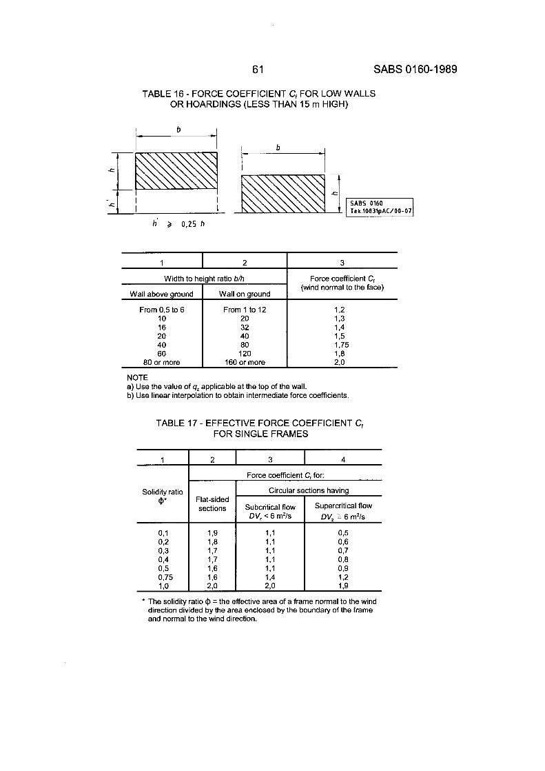
61 SABS 01 60-1 989
Width to height ratio b/h
Wall above around Wall on around
TABLE 16 - FORCE COEFFICIENT C, FOR LOW WALLS OR HOARDINGS (LESS THAN 15 rn HIGH)
Force coefficient C, (wind normal to the face)
I- b
From 0,5 to 6 10 16 20 40 60
80 or more
Tek.10831pAC/00-07
h' 3 0,25 h
From 1 to 12 1 2 20 1.3 32 1.4 40 1.5 80 1.75 120 1 8
160 or more 2.0
1 I 2 I 3
1 2 I 3 I 4
Force coefficient C, for: I
TABLE 17 - EFFECTIVE FORCE COEFFICIENT C, FOR SINGLE FRAMES
* The solidity ratio I$ = the effective area of a frame normal to the wind direction divided by the area enclosed by the boundary of the frame and normal to the wind direction.
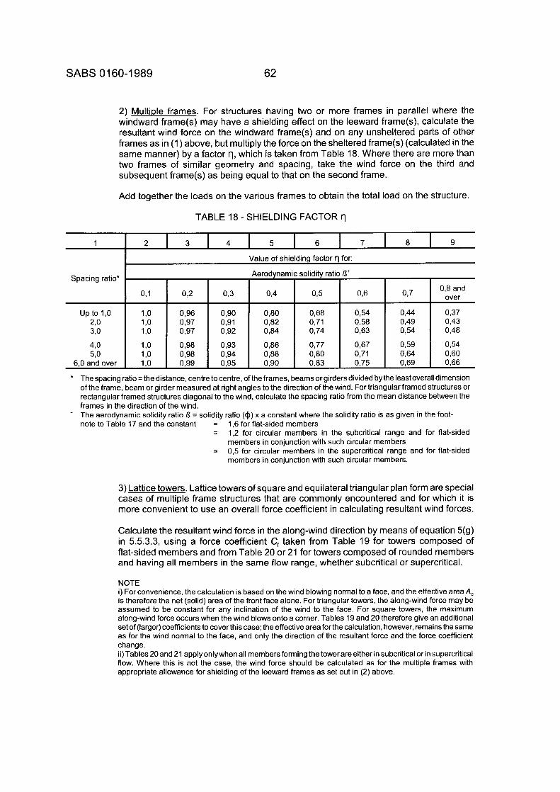
SABS 01 60-1 989 62
Spacing ratio*
u p to l , o 2.0 3,O
4 0 5,O
6,O and over
2) Multiple frames. For structures having two or more frames in parallel where the windward frame(s) may have a shielding effect on the leeward frame(s), calculate the resultant wind force on the windward frame(s) and on any unsheltered parts of other frames as in (1) above, but multiply the force on the sheltered frame(s) (calculated in the same manner) by a factor rl, which is taken from Table 18. Where there are more than two frames of similar geometry and spacing, take the wind force on the third and subsequent frame(s) as being equal to that on the second frame.
Add together the loads on the various frames to obtain the total load on the structure.
0,1 092 0 3
1 ,o 0,96 0,90 1 ,o 0,97 0,91 1 ,o 0,97 0,92
1 ,o o,ga 0,93 1 ,o 0,98 0.94 1 ,o 0,99 0,95
TABLE 18 - SHIELDING FACTOR tl
1 2 I 3 I 4 I 5 I 6 I 7 I a I 9
I Value of shielding factor r l for:
brodynan
0,4
o,ao o,a2 o,a4
o,a6 o,aa 0,90
solidity ratis
0 3
0,6a 0,71 0,74
0,77 o,ao o,a3
0,8 and
0,49 0,43 0,63
* The spacing ratio = the distance, centre to centre, of the frames, beams or girders divided bythe least overall dimension of the frame, beam or girder measured at right angles to the direction of the wind. For triangular framed structures or rectangular framed structures diagonal to the wind, calculate the spacing ratio from the mean distance between the frames in the direction of the wind. The aerodynamic solidity ratio f i = solidity ratio (a) x a constant where the solidity ratio is as given in the foot- note to Table 17 and the constant = 1,6 for flat-sided members
=
=
+
1,2 for circular members in the subcritical range and for flat-sided members in conjunction with such circular members 0,5 for circular members in the supercritical range and for flat-sided members in conjunction with such circular members.
3) Lattice towers. Lattice towers of square and equilateral triangular plan form are special cases of multiple frame structures that are commonly encountered and for which it is more convenient to use an overall force coefficient in calculating resultant wind forces.
Calculate the resultant wind force in the along-wind direction by means of equation 5(g) in 5.5.3.3, using a force coefficient C, taken from Table 19 for towers composed of flat-sided members and from Table 20 or 21 for towers composed of rounded members and having all members in the same flow range, whether subcritical or supercritical.
NOTE i) For convenience, the calculation is based on the wind blowing normal to a face, and the effective area A, is therefore the net (solid) area of the front face alone. For triangular towers, the along-wind force may be assumed to be constant for any inclination of the wind to the face. For square towers, the maximum along-wind force occurs when the wind blows onto a corner. Tables 19 and 20 therefore give an additional set of (larger) coefficients to cover this case; the effective area for the calculation, however, remains the same as for the wind normal to the face, and only the direction of the resultant force and the force coefficient change. ii)Tables20and 21 applyonlywhenall membersforming thetowerareeitherinsubcriticalor in supercritical flow. Where this is not the case, the wind force should be calculated as for the multiple frames with appropriate allowance for shielding of the leeward frames as set out in (2) above.
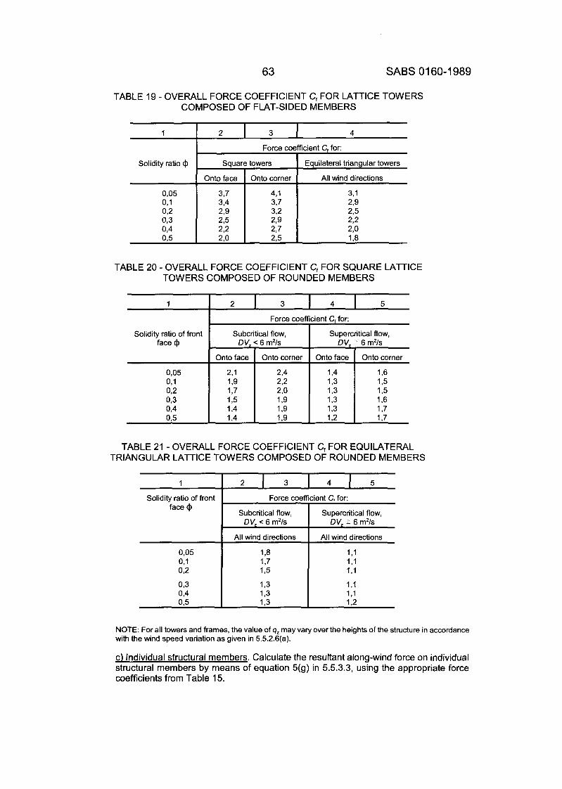
63 SABS 01 60-1 989
Kcient C, for:
Equilateral triangular towers
All wind directions
23 23 2 2 2,o 1 3
3,1
TABLE 19 - OVERALL FORCE COEFFICIENT Cf FOR LATTICE TOWERS COMPOSED OF FLAT-SIDED MEMBERS
1
Solidity ratio of front face @
0,05 0,l
03 0.2
0,4 03
1 I 2 I 3 I 4
2 1 3 I 4 I 5
Force coefficient C, for:
Subcritical flow, Supercritical flow,
Onto face Onto corner Onto face Onto corner
2,1 2,4 1,4 1.6 1,9 22 13 1.5
1 3 13 1,3 1,6
DV, < 6 m2/s DV, 1 6 m2/s
1,7 2,o 1,3 1,5
1,4 1,9 13 1,7 1,4 1,9 12 1,7
Solidity ratio @
Force coefficient C, for:
1 Subcritical flow, Supercritical flow, 1 DV, < 6 m2/s DV, ~ 6 m2/s
All wind directions All wind directions
13 1,1 1,7 1 ,I 1 3 1,l
13 1.1 13 1.1
Force cof
Square towers
2,9 2,9
2.2
TABLE 21 - OVERALL FORCE COEFFICIENT Cf FOR EQUILATERAL TRIANGULAR LATTICE TOWERS COMPOSED OF ROUNDED MEMBERS
1 I 2 I 3 I 4 I 5 Solidity ratio of front
face @
NOTE: For all towers and frames, the value of qz may vary over the heights of the structure in accordance with the wind speed variation as given in 5.5.2.6(a).
c) Individual structural members. Calculate the resultant along-wind force on individual structural members by means of equation 5(g) in 5.5.3.3, using the appropriate force coefficients from Table 15.
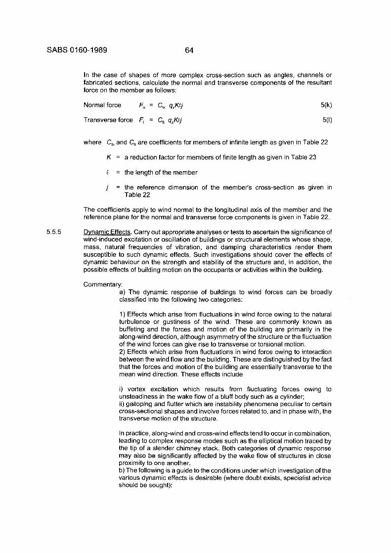
SABS 0 160-1 989 64
In the case of shapes of more complex cross-section such as angles, channels or fabricated sections, calculate the normal and transverse components of the resultant force on the member as follows:
Transverse force Ft = C, 9,KOj 5(1)
where C, and C, are coefficients for members of infinite length as given in Table 22
K = a reduction factor for members of finite length as given in Table 23
Q = the length of the member
j = the reference dimension of the member's cross-section as given in Table 22
The coefficients apply to wind normal to the longitudinal axis of the member and the reference plane for the normal and transverse force components is given in Table 22.
5.5.5 Dvnamic Effects. Carry out appropriate analyses or tests to ascertain the significance of windinduced excitation or oscillation of buildings or structural elements whose shape, mass, natural frequencies of vibration, and damping characteristics render them susceptible to such dynamic effects. Such investigations should cover the effects of dynamic behaviour on the strength and stability of the structure and, in addition, the possible effects of building motion on the occupants or activities within the building.
Commentary: a) The dynamic response of buildings to wind forces can be broadly classified into the following two categories:
1) Effects which arise from fluctuations in wind force owing to the natural turbulence or gustiness of the wind. These are commonly known as buffeting and the forces and motion of the building are primarily in the along-wind direction, although asymmetry of the structure or the fluctuation of the wind forces can give rise to transverse or torsional motion. 2) Effects which arise from fluctuations in wind force owing to interaction between the wind flow and the building. These are distinguished by the fact that the forces and motion of the building are essentially transverse to the mean wind direction. These effects include
i) vortex excitation which results from fluctuating forces owing to unsteadiness in the wake flow of a bluff body such as a cylinder; ii) galloping and flutter which are instability phenomena peculiar to certain cross-sectional shapes and involve forces related to, and in phase with, the transverse motion of the structure.
In practice, along-wind and cross-wind effects tend to occur in combination, leading to complex response modes such as the elliptical motion traced by the tip of a slender chimney stack. Both categories of dynamic response may also be significantly affected by the wake flow of structures in close proximity to one another. b) The following is a guide to the conditions under which investigation of the various dynamic effects is desirable (where doubt exists, specialist advice should be sought):
65 SABS 01 60-1 989
0 45 90
TABLE 22 - NORMAL AND TRANSVERSE FORCE COEFFICIENTS Cfn
LENGTH AND OF FLAT-SIDED CROSS-SECTION AND C, FOR INDIVIDUAL STRUCTURAL MEMBERS OF INFINITE
+1,6 0 +2,0 0 +2,1 0 +2.0 0 +1,4 0 +2,05 0 +1,2 +1,6 +1,95 +0,6 +1,5 +1,5 +1,8 +0,1 +1,4 +0,7 +1,55 +I,% +2,0 0 +2,2 +0,5 +0,9 0 +1,9 0 +0,1 0 +0,75 0
1 2 3
Lengthlfrontal width Qlis
5 10
K 0,6 0,70
NOTE: In this table the normal and transverse force coefficients C," and C,, are given in relation to the dimension j and not, as in other cases, in relation to the effective frontal area A.
4 5 6 7 8
20 30 50 100 00
0,80 0,85 0,90 0,95 1,0
TABLE 23 - REDUCTION FACTOR K FOR STRUCTURAL MEMBERS OF FINITE LENGTH AND SLENDERNESS
AND OF FLAT-SIDED CROSS-SECTION
SABS 01 60-1 989 66 (As amended 1991 and 1993)
1 ) Along-wind buffeting: Significant dynamic response may occur in tall buildings, masts, towers and stacks, or other slender structures exceeding 100 m in height or with a ratio of height to minimum effective width of 5 or more or with natural periods of vibration longer than 1 s . Some analytical methods for predicting the response of structures to buffeting, such as the so-called gust-energy methods, are based on the use of a maximum mean hourly wind speed rather than a maximum 3 s gust speed. D-I of Appendix D includes a map of mean hourly wind speeds with a 50-year return period. 2) Vortex excitation: Lightly damped, slender structures of circular or near circular cross-section such as unlined, welded steel chimney stacks are particularly prone to this form of excitation but slender concrete stacks, towers and unusually slender, tall buildings of similar cross-section may also require investigation. 3) Galloping: This tends to be confined to extremely slender, low mass, lightly damped structures or elements of triangular, rectangular, or D-shaped cross-section. The classical example is that of iced powerlines or iced stay cables, and it is seldom a problem in building structures. Wind tunnel testing may be required to determine the critical parameters. 4) Flutter: This is typically a problem with long-span bridge decks of low stiffness such as those in suspension bridges. Wind tunnel tests are commonly used to investigate the problem.
Reference should be made to A-2 of Appendix A for a list of publications in relation to the above phenomena.
5.5.6 Simplified Wind Load Desian. The simplified wind forces set out below may be adapted for design purposes, provided that the building complies with the following requirements:
- it is rectangular in plan, and - its overall height does not exceed 20 m, and -the ratio of its overall height to its lesser plan dimension does not exceed 4.
The values given allow for internal positive or negative pressurization resulting from a dominant opening in one wall. (Refer also to Subsection (a) of the Commentary to 5.5.1 .)
a) For the overall wind forces for stability analysis:
1) A horizontal force due to a pressure of 1 ,I q, N/m2 acting on the projected area of the building (including its roof) normal to the wind direction; 2) an upward force due to a pressure of 1,6 q, N/m2 acting on the plan area of the roof.
b) For the design of a wall as a whole and for the design of wall claddings and their fixings in regions other than those given in (c) below, a pressure on the external surFace of the wall of
+I ,6 q, N/m2 or -1,4 q, N/m2
Amdt 3, Oct. 1993
c) For the design of wall claddings and their fixings in areas within a distance h from the corners of the building, or 0,15 w (whichever is less), a pressure on the external surface of the wall of
+I ,6 q, N/m2 or -1 ,8q, N/m2
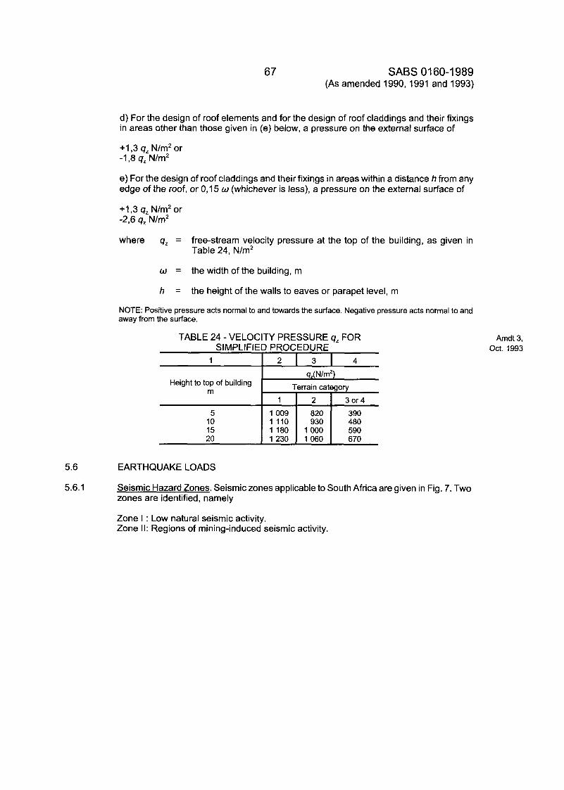
5.6
5.6.1
Height to top of building m
5 10 15 20
67 SABS 01 60-1 989 (As amended 1990,1991 and 1993)
4z(N/m2) Terrain category
1 2 3or4
1009 820 390 1 110 930 480 1 180 1000 590 1230 1060 670
d) For the design of roof elements and for the design of roof claddings and their fixings in areas other than those given in (e) below, a pressure on the external surface of
+I ,3 q, N/m2 or -1,8 q, N/m2
e) For the design of roof claddings and their fixings in areas within a distance h from any edge of the roof, or 0,15 w (whichever is less), a pressure on the external surface of
+I ,3 q, N/m2 or -2,6 q, N/m2
where q, = free-stream velocity pressure at the top of the building, as given in Table 24, N/m2
w = the width of the building, m
h = the height of the walls to eaves or parapet level, rn
NOTE: Positive pressure acts normal to and towards the surface. Negative pressure acts normal to and away from the surface.
TABLE 24 - VELOCITY PRESSURE q, FOR SIMPLIFIED PROCEDURE
EARTHQUAKE LOADS
Seismic Hazard Zones. Seismic zones applicable to South Africa are given in Fig. 7. Two zones are identified, namely
Zone I : Low natural seismic activity. Zone II: Regions of mining-induced seismic activity.
Amdt 3, Oct. 1993
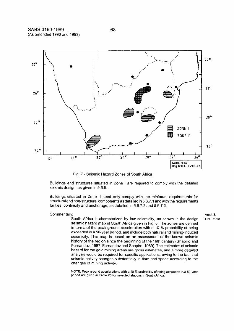
SABS 01 60-1 989 (As amended 1990 and 1993)
68
2 2'
2 6'
30'
34'
22'
2 6'
30'
34'
Fig. 7 - Seismic Hazard Zones of South Africa
Buildings and structures situated in Zone I are required to comply with the detailed seismic design, as given in 5.6.5.
Buildings situated in Zone II need only comply with the minimum requirements for structural and non-structural components as detailed in 5.6.7.1 and with the requirements for ties, continuity and anchorage, as detailed in 5.6.7.2 and 5.6.7.3.
Commentary: Amdt 3, South Africa is characterized by low seismicity, as shown in the design seismic hazard map of South Africa given in Fig. 8. The zones are defined in terms of the peak ground acceleration with a 10 % probability of being exceeded in a 50-year period, and include both natural and mining-induced seismicity. This map is based on an assessment of the known seismic history of the region since the beginning of the 19th century (Shapiro and Fernandez, 1987; Fernandez and Shapiro, 1989). The estimates of seismic hazard for the gold mining areas are gross estimates, and a more detailed analysis would be required for specific applications, owing to the fact that seismic activity changes substantially in time and space according to the changes of mining activity.
NOTE: Peak ground accelerations with a 10 % probability of being exceeded in a 50-year period are given in Table 25 for selected stations in South Africa.
Oct. 1993
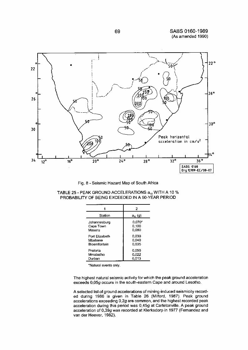
69
Station
Johannesburg Cape Town Maseru
Port Elizabeth Mbabane Bloemfontein
Pretoria Mmabatho Durban
SABS 01 60-1 989 (As amended 1990)
a10 (9) 0,070* 0,100 0,080
0,030 0,040 0,035
0,050 0,022 0,013
22
26
30
3 4
Fig. 8 - Seismic Hazard Map of South Africa
TABLE 25 - PEAK GROUND ACCELERATIONS a,, WITH A 10 % PROBABILITY OF BEING EXCEEDED IN A 50-YEAR PERIOD
1 I 2
‘Natural events only.
The highest natural seismic activity for which the peak ground acceleration exceeds 0,05g occurs in the south-eastern Cape and around Lesotho.
A selected list of ground accelerations of mining-induced seismicity record- ed during 1986 is given in Table 26 (Milford, 1987). Peak ground accelerations exceeding 0,2g are common, and the highest recorded peak acceleration during this period was 0,45g at Carletonville. A peak ground acceleration of 0,39g was recorded at Klerksdorp in 1977 (Fernandez and van der Heever, 1982).
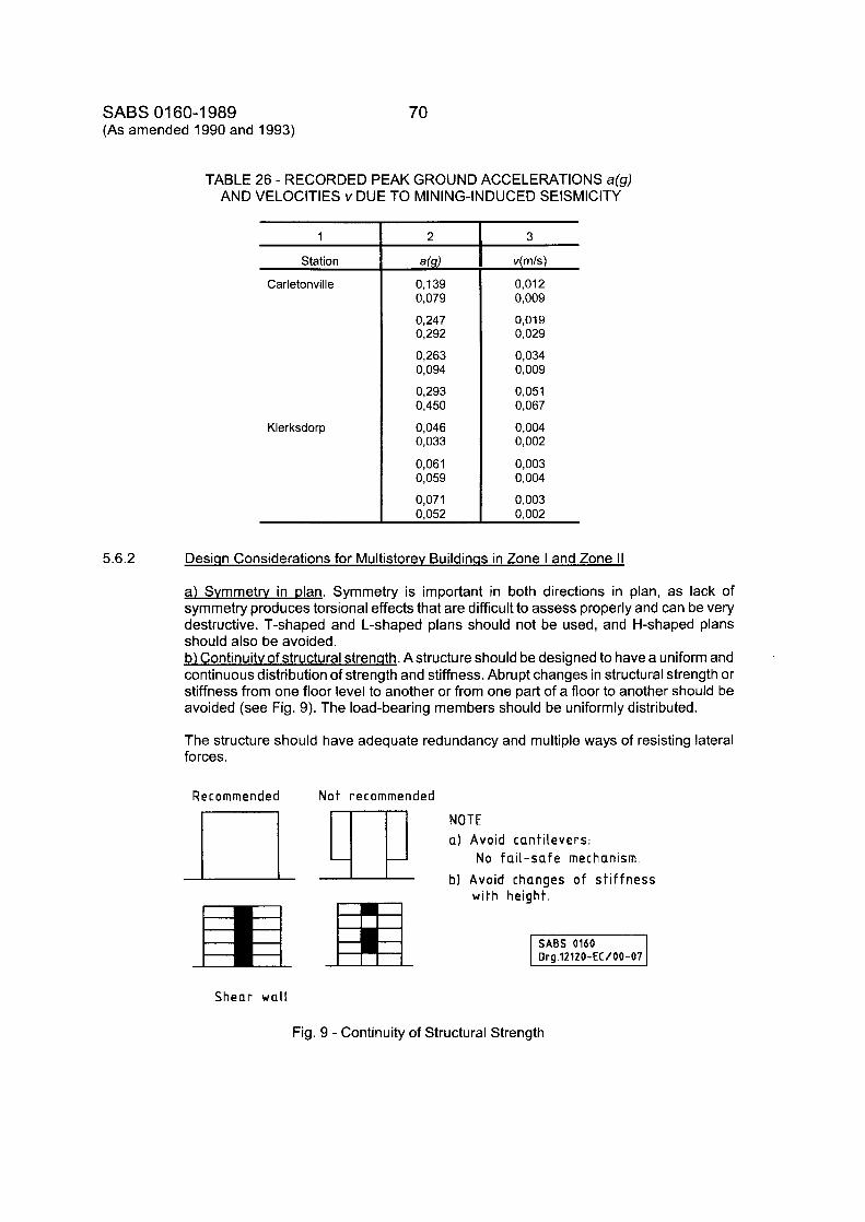
SABS 01 60-1 989 70 (As amended 1990 and 1993)
TABLE 26 - RECORDED PEAK GROUND ACCELERATIONS a(g) AND VELOCITIES v DUE TO MINING-INDUCED SElSMlClTY
1
Station
Carletonville
Klerksdorp
2
4 s ) 0,139 0,079
0,247 0,292
0,263 0,094
0,293 0,450
0,046 0,033
0,061 0,059
0,071 0,052
3
v( m/s)
0,012 0,009
0,019 0,029
0,034 0,009
0,051 0,067
0,004 0,002
0,003 0,004
0,003 0.002
5.6.2 Desiqn Considerations for Multistorev Buildinqs in Zone I and Zone II
a) Svmmetrv in plan. Symmetry is important in both directions in plan, as lack of symmetry produces torsional effects that are difficult to assess properly and can be very destructive. T-shaped and L-shaped plans should not be used, and H-shaped plans should also be avoided. b) Continuitv of structural strenath. Astructure should be designed to have a uniform and continuous distribution of strength and stiffness. Abrupt changes in structural strength or stiffness from one floor level to another or from one part of a floor to another should be avoided (see Fig. 9). The load-bearing members should be uniformly distributed.
The structure should have adequate redundancy and multiple ways of resisting lateral forces.
Recommended N o t recommended
a) Avoid cantilevers: No fail-safe mechanism
b) Avoid changes of stiffness wi th height
Shear wall
Fig. 9 - Continuity of Structural Strength
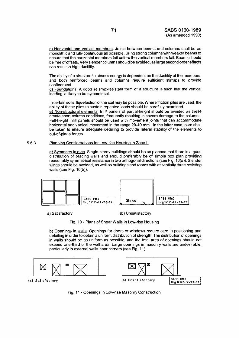
71 SABS 01 60-1 989 (As amended 1990)
5.6.3
c) Horizontal and vertical members. Joints between beams and columns shall be as monolithic and fully continuous as possible, using strong columns with weaker beams to ensure that the horizontal members fail before the vertical members fail. Beams should be free of offsets. Very slender columns should be avoided, as large second order effects can result in high ductility.
The ability of a structure to absorb energy is dependent on the ductility of the members, and both reinforced beams and columns require sufficient stirrups to provide confinement. d) Foundations. A good seismic-iresistant form of a structure is such that the vertical loading is likely to be symmetrical.
In certain soils, liquefaction of the :jail may be possible. Where friction piles are used, the ability of these piles to sustain repeated loads should be carefully examined. e) Non-structural elements. lnfill panels of partial-height should be avoided as these create short column conditions, frequently resulting in severe damage to the columns. Full-height infill panels should be used with movement joints that can accommodate horizontal and vertical movement in the range 20-40 mm . In the latter case, care shall be taken to ensure adequate detailing to provide lateral stability of the elements to out-of-plane forces.
Plannina Considerations for Low-rise Housina in Zone II
a) Svmmetrv in dan. Single-storey buildings should be so planned that there is a good distribution of bracing walls and should preferably be of simple box plan providing reasonably symmetrical resistance in two orthogonal directions (see Fig. 1 O(a)). Slender wings should be avoided, as well as buildings and rooms with essentially three resisting walls (see Fig. 10(b)).
iH7R a) Satisfactory (b) Unsatisfactory
Fig. 10 - Plans of Shear Walls in Low-rise Housing
b) ODeninqs in walls. Openings for doors or windows require care in positioning and detailing in order to obtain a uniform distribution of strength. The distribution of openings in walls should be as uniform as possible, and the total area of openings should not exceed one-third of the wall area. Large openings in masonry walls are undesirable, particularly in external walls near corners (see Fig. 11).
Org 12122-EC/00-07 (a) Satisfactory (b) unsatisfactory
Fig. 11 - Openings in Low-rise Masonry Construction
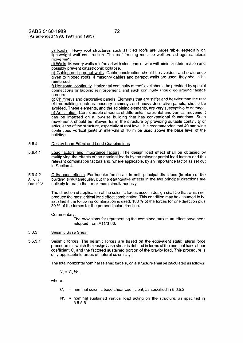
SABS 01 60-1 989 72 (As amended 1990,1991 and 1993)
c) Roofs. Heavy roof structures such as tiled roofs are undesirable, especially on lightweight wall construction. The roof framing must be well braced against lateral movement. d) Walls. Masonry walls reinforced with steel bars or wire will minimize deformation and possibly prevent catastrophic collapse. e) Gables and parapet walls. Gable construction should be avoided, and preference given to hipped roofs. If masonry gables and parapet walls are used, they should be reinforced. f) Horizontal continuity. Horizontal continuity at roof level should be provided by special connections or lapping reinforcement, and such continuity should go around facade corners. q) Chimneys and decorative panels. Elements that are stiffer and heavier than the rest of the building, such as masonry chimneys and heavy decorative panels, should be avoided. These elements, and the adjoining elements, are very susceptible to damage. h) Articulation. Considerable amounts of differential horizontal and vertical movement can be imposed on a low-rise building that has conventional foundations. Such movements should be allowed for in the structure by providing suitable continuity or articulation of the structure, especially at roof level. It is recommended that 40 mm wide continuous vertical joints at intervals of 10 m be used above the base level of the bu i Idi ng .
Desian Load Effect and Load Combinations
Load factors and importance factors. The design load effect shall be obtained by multiplying the effects of the nominal loads by the relevant partial load factors and the relevant combination factors and, where applicable, by an importance factor as set out in Section 4.
5.6.4
5.6.4.1
5.6.4.2 Arndt 3, Oct. 1993
Orthoaonal effects. Earthquake forces act in both principal directions (in plan) of the building simultaneously, but the earthquake effects in the two principal directions are unlikely to reach their maximum simultaneously.
The direction of application of the seismic forces used in design shall be that which will produce the most critical load effect combination. This condition may be assumed to be satisfied if the following combination is used: 100 % of the forces for one direction plus 30 % of the forces for the perpendicular direction.
Commentary: The provisions for representing the combined maximum effect have been adopted from ATC3-06.
5.6.5 Seismic Base Shear
5.6.5.1 Seismic forces. The seismic forces are based on the equivalent static lateral force procedure, in which the design base shear is defined in terms of the nominal base shear coefficient C, and the factored sustained portion of the gravity load. This procedure is only applicable to areas of natural seismicity.
The total horizontal nominal seismic force V,, on a structure shall be calculated as follows:
v,, = c,.w,, where
C, = nominal seismic base shear coefficient, as specified in 5.6.5.2
W,, = nominal sustained vertical load acting on the structure, as specified in 5.6.5.6
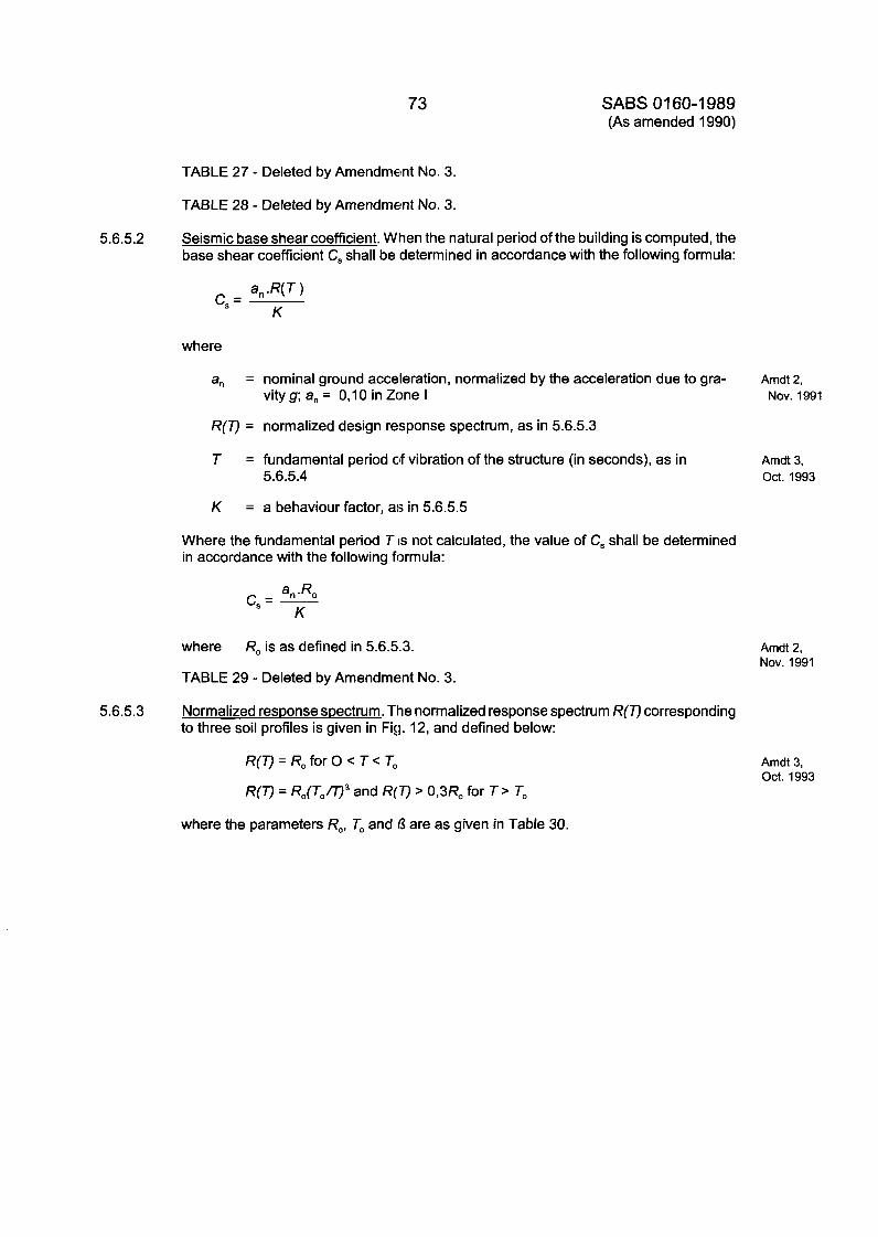
73 SABS 0 1 60- 1 989 (As amended 1990)
TABLE 27 - Deleted by Amendment No. 3.
TABLE 28 - Deleted by Amendment No. 3.
5.6.5.2 Seismic base shear coefficient. When the natural period of the building is computed, the base shear coefficient C, shall be determined in accordance with the following formula:
where
a,
R(T) = normalized design response spectrum, as in 5.6.5.3
= nominal ground acceleration, normalized by the acceleration due to gra- vity g; a, = 0,lO in Zone I
T = fundamental period of vibration of the structure (in seconds), as in 5.6.5.4
K = a behaviour factor, as in 5.6.5.5
Where the fundamental period T lis not calculated, the value of C, shall be determined in accordance with the following formula:
a" .Rcl c,= - K
where
TABLE 29 - Deleted by Amendment No. 3.
Ro is as defined in 5.6.5.3.
5.6.5.3 Normalized resDonse spectrum. The normalized response spectrum R(T) corresponding to three soil profiles is given in Fig. 12, and defined below:
R(T)=RoforO< T < To
R(V = Ro(T0mR and R(T) > 0,3R, for T > To
Amdt 2, Nov. 1991
Amdt 3, Oct. 1993
Amdt 2, Nov. 1991
Amdt 3, Oct. 1993
where the parameters Ro, To and 0 are as given in Table 30.
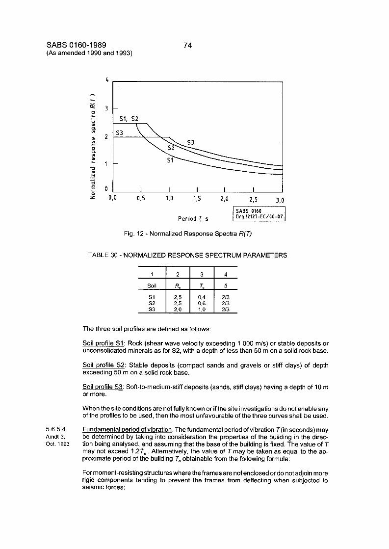
SABS 01 60-1 989 (As amended 1990 and 1993)
1
Soil
s1 s 2 s 3
5.6.5.4 Amdt 3 , Oct. 1993
2 3 4
R, To n 2 3 0,4 213 2,5 0,6 213 2 0 1 ,o 213
74
I s1. s2
rl 0,o 0,s
Drg.12127-EC/00-07 Period T s
Fig. 12 - Normalized Response Spectra R(T)
TABLE 30 - NORMALIZED RESPONSE SPECTRUM PARAMETERS
The three soil profiles are defined as follows:
Soil profile S1: Rock (shear wave velocity exceeding 1 000 m/s) or stable deposits or unconsolidated minerals as for S2, with a depth of less than 50 m on a solid rock base.
Soil profile S2: Stable deposits (compact sands and gravels or stiff clays) of depth exceeding 50 m on a solid rock base.
Soil profile S3: Soft-to-medium-stiff deposits (sands, stiff clays) having a depth of 10 m or more.
When the site conditions are not fully known or if the site investigations do not enable any of the profiles to be used, then the most unfavourable of the three curves shall be used.
Fundamental period of vibration. The fundamental period of vibration T(in seconds) may be determined by taking into consideration the properties of the building in the direc- tion being analysed, and assuming that the base of the building is fixed. The value of T may not exceed 1 ,2T, . Alternatively, the value of T may be taken as equal to the ap- proximate period of the building T, obtainable from the following formula:
For moment-resisting structures where the frames are not enclosed or do not adjoin more rigid components tending to prevent the frames from deflecting when subjected to seismic forces:
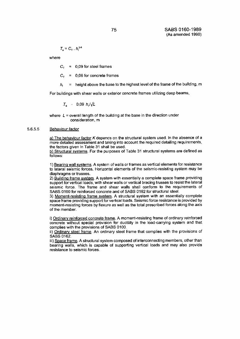
75
T, = C, . h,3’4
where
SABS 01 60-1 989 (As amended 1990)
C, = 0,09 for steel frames
C, = 0,06 for concrete frames
h, = height above the base to the highest level of the frame of the building, m
For buildings with shear walls or exterior concrete frames utilizing deep beams,
.T, = 0,09 h+ l f i
where L = overall length of the building at the base in the direction under consideration, m
5.6.5.5 Behaviour factor
a) The behaviour factor K depends on the structural system used. In the absence of a more detailed assessment and taking into account the required detailing requirements, the factors given in Table 31 shall be used. b l Structural svstems. For the purposes of Table 31 structural systems are defined as follows:
1) Bearincl wall svstems. A system of walls or frames as vertical elements for resistance to lateral seismic forces. Horizontal elements of the seismic-resisting system may be diaphragms or trusses. 2) Buildina frame svstem. A system with essentially a complete space frame providing support for vertical loads, with shear walls or vertical bracing trusses to resist the lateral seismic force. The frame and :shear walls shall conform to the requirements of SABS 0100 for reinforced concrete and of SABS 0162 for structural steel. 3) Moment-resistincl frame svstern. A structural system with an essentially complete space frame providing support for vertical loads. Seismic force resistance is provided by moment-resisting forces by flexure as well as the total prescribed forces along the axis of the member.
i) Ordinarv reinforced concrete frame. A moment-resisting frame of ordinary reinforced concrete without special provision for ductility in the load-carrying system and that complies with the provisions of SHBS 0100. ii) Ordinarv steel frame. An ordinary steel frame that complies with the provisions of SABS 0162. iii) Space frame. A structural system composed of interconnecting members, other than bearing walls, which is capable of supporting vertical loads and may also provide resistance to seismic forces.
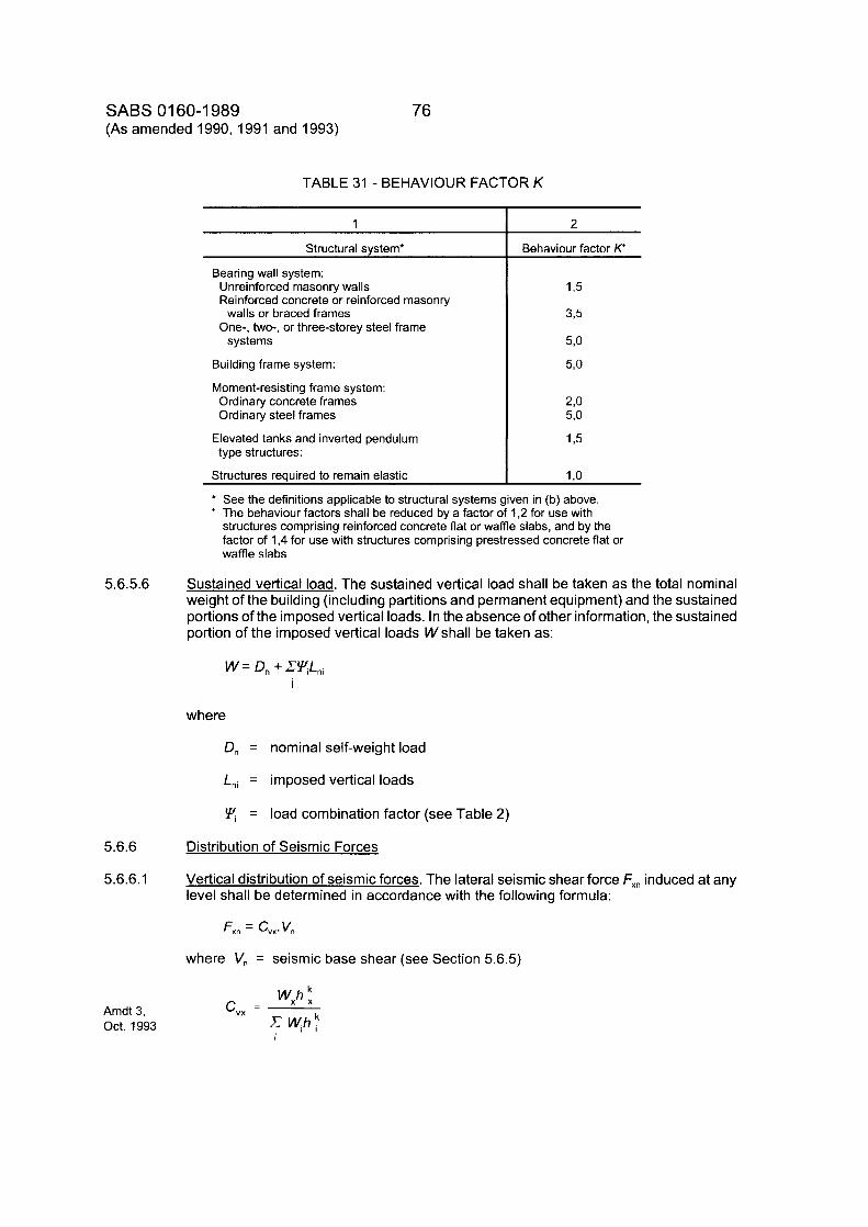
SABS 01 60-1 989 (As amended 1990,1991 and 1993)
76
TABLE 31 - BEHAVIOUR FACTOR K
1
Structural system*
Bearing wall system: Unreinforced masonry walls Reinforced concrete or reinforced masonry
One-, two-, or three-storey steel frame walls or braced frames
systems
Building frame system:
Moment-resisting frame system: Ordinary concrete frames Ordinary steel frames
type structures: Elevated tanks and inverted pendulum
Structures required to remain elastic
2
Behaviour factor K+
* See the definitions applicable to structural systems given in (b) above. + The behaviour factors shall be reduced by a factor of 1,2 for use with
structures comprising reinforced concrete flat or waffle slabs, and by the factor of 1,4 for use with structures comprising prestressed concrete flat or waffle slabs
5.6.5.6 Sustained vertical load. The sustained vertical load shall be taken as the total nominal weight of the building (including partitions and permanent equipment) and the sustained portions of the imposed vertical loads. In the absence of other information, the sustained portion of the imposed vertical loads W shall be taken as:
W = D, + CYL,, I
where
D, = nominal self-weight load
Lni = imposed vertical loads
= load combination factor (see Table 2)
5.6.6 Distribution of Seismic Forces
5.6.6.1 Vertical distribution of seismic forces. The lateral seismic shear force Fx, induced at any level shall be determined in accordance with the following formula:
where V,, = seismic base shear (see Section 5.6.5)
Amdt 3, Oct. 1993
Wxh : c,, = - Wihr
I
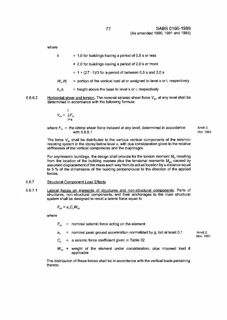
77 SABS 01 60-1989 (As amended 1990,1991 and 1993)
where
k = 1 ,O for buildings having a period of 0,5 s or less
= 2,O for buildings having a period of 2,O s or more
= 1 + (2T- 1)/3 for a period of between 0,5 s and 2,O s
W,,Wi
h,,hi
= portion of the vertical load at or assigned to level x or i, respectively
= height above the base to level x or i, respectively
5.6.6.2 Horizontal shear and torsion. The nominal seismic shear force V,,, at any level shall be determined in accordance with the following formula:
t V,, = ZFi,
I=x
where F,, = the lateral shear force induced at any level, determined in accordance
The force V,, shall be distributed to the various vertical components of the seismic- resisting system in the storey below level x, with due consideration given to the relative stiffnesses of the vertical components and the diaphragm.
For asymmetric buildings, the design shall provide for the torsion moment M,, resulting from the location of the building masses plus the tensional moments M,,, caused by assumed displacement of the mass each way from its actual location by a distance equal to 5 % of the dimensions of the Ixdding perpendicular to the direction of the applied forces.
Amdt 3, with 5.6.6.1 Oct. 1993
5.6.7 Structural ComDonent Load Effects
5.6.7.1 Lateral forces on elements of structures and non-structural comDonents. Parts of structures, non-structural components, and their anchorages to the main structural system shall be designed to resist a lateral force equal to
where
Fpn = nominal seismic force acting on the element
a, = nominal peak ground acceleration normalized by g, but at least 0,l Amdt 2,
C, = a seismic force coefficient given in Table 32 Nov. 1991
Wpn = weight of the element under consideration, plus imposed load if applicable
The distribution of these forces shall be in accordance with the vertical loads pertaining thereto.
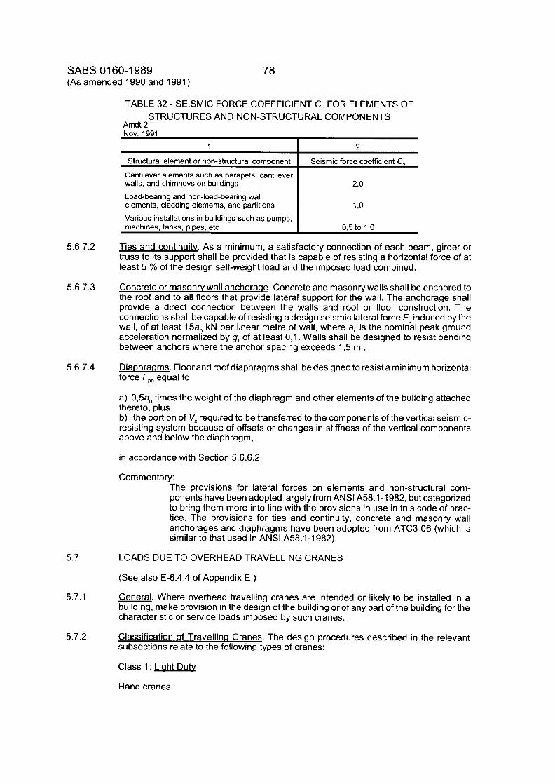
SABS 01 60-1 989 (As amended 1990 and 1991)
1
Structural element or non-structural component
Cantilever elements such as parapets, cantilever walls, and chimneys on buildings
Load-bearing and non-load-bearing wall elements, cladding elements, and partitions
Various installations in buildings such as pumps, machines, tanks, pipes, etc
78
2
Seismic force coefficient C,
2,o
1 ,o
O,5 to 1,O
TABLE 32 - SEISMIC FORCE COEFFICIENT C, FOR ELEMENTS OF STRUCTURES AND NON-STRUCTURAL COMPONENTS
Amdt 2, Nov. 1991
5.6.7.4 DiaDhraams. Floor and roof diaphragms shall be designed to resist a minimum horizontal force FDn equal to
a) 0,5a, times the weight of the diaphragm and other elements of the building attached thereto, plus b) the portion of V, required to be transferred to the components of the vertical seismic- resisting system because of offsets or changes in stiffness of the vertical components above and below the diaphragm,
in accordance with Section 5.6.6.2.
Commentary: The provisions for lateral forces on elements and non-structural com- ponents have been adopted largelyfrom ANSl A58.1-1982, but categorized to bring them more into line with the provisions in use in this code of prac- tice. The provisions for ties and continuity, concrete and masonry wall anchorages and diaphragms have been adopted from ATC3-06 (which is similar to that used in ANSl A58.1-1982).
5.7
5.7.1
5.7.2
LOADS DUE TO OVERHEAD TRAVELLING CRANES
(See also E-6.4.4 of Appendix E.)
General. Where overhead travelling cranes are intended or likely to be installed in a building, make provision in the design of the building or of any part of the building for the characteristic or service loads imposed by such cranes.
Classification of Travellina Cranes. The design procedures described in the relevant subsections relate to the following types of cranes:
Class 1: Liaht Dutv
Hand cranes
79
Class 2: Medium Dutv
SABS 01 60-1 989 (As amended 1990)
Cranes for general use in factories and workshops Warehouse cranes - intermittent operation Power station cranes Machine shop cranes Foundry cranes
Class 3: Heavv Dub
Warehouse cranes - continuous operation Scrapyard cranes
Rolling mill cranes Grab and magnet cranes - intermittent operation Ladle cranes in steelworks
Class 4: Extra Heavv Duty
Grab and magnet cranes - continuous operation Soaking pit cranes Ingot stripping cranes Furnace charging cranes Forging cranes Claw cranes
Commentary: The types of cranes listed cover most of those likely to be encountered in practice, but the list cannot be all-inclusive. In the case of crane types not covered, the owner should decide the class of crane, preferably in consul- tation with the crane supplier.
The designer or owner may, at his discretion, allocate to any crane a higher classification than is indicated in this subsection.
5.7.3 Vertical Wheel Loads. Take as the vertical wheel loads imposed on the gantry by a crane the values provided by the crane manufacturer or specified by the owner. These are referred to as the static wheel loads.
Make an allowance for impact and other dynamic effects in the vertical direction by multiplying the static wheel load by the appropriate of the following factors:
Class 1 cranes : 1 ,I 0 Class 2 cranes : 1,20 Class 3 cranes : 1,251 Class 4 cranes : 1,30
Commentary: It is important that crane loads be accurately ascertained as regards both the wheel loads and their spacings. Where it is necessary to use a preliminary assessment of crane loads in the design, this should be checked against the actual loads once these are finalized. It should never be assumed that incorrect loading information can be compensated for by the impact factor.
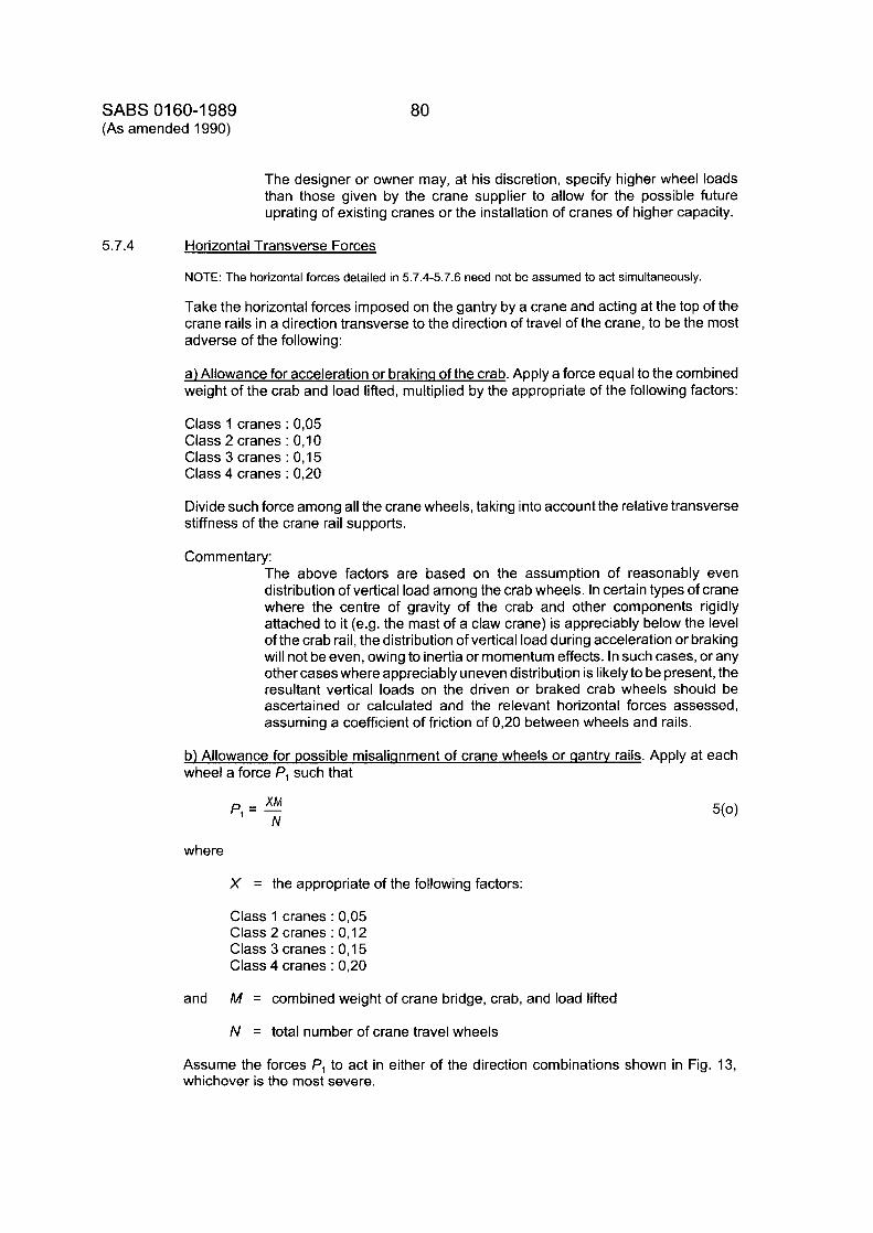
SABS 01 60-1 989 (As amended 1990)
80
5.7.4
The designer or owner may, at his discretion, specify higher wheel loads than those given by the crane supplier to allow for the possible future uprating of existing cranes or the installation of cranes of higher capacity.
Horizontal Transverse Forces
NOTE: The horizontal forces detailed in 5.7.4-5.7.6 need not be assumed to act simultaneously.
Take the horizontal forces imposed on the gantry by a crane and acting at the top of the crane rails in a direction transverse to the direction of travel of the crane, to be the most adverse of the following:
a) Allowance for acceleration or brakinq of the crab. Apply a force equal to the combined weight of the crab and load lifted, multiplied by the appropriate of the following factors:
Class 1 cranes : 0,05 Class 2 cranes : 0,lO Class 3 cranes : 0,15 Class 4 cranes : 0,20
Divide such force among all the crane wheels, taking into account the relative transverse stiffness of the crane rail supports.
Commentary: The above factors are based on the assumption of reasonably even distribution of vertical load among the crab wheels. In certain types of crane where the centre of gravity of the crab and other components rigidly attached to it (e.g. the mast of a claw crane) is appreciably below the level of the crab rail, the distribution of vertical load during acceleration or braking will not be even, owing to inertia or momentum effects. In such cases, or any other cases where appreciably uneven distribution is likely to be present, the resultant vertical loads on the driven or braked crab wheels should be ascertained or calculated and the relevant horizontal forces assessed, assuming a coefficient of friction of 0,20 between wheels and rails.
b) Allowance for Dossible misaliqnment of crane wheels or qantw rails. Apply at each wheel a force P, such that
X M p = - ' N
where
X = the appropriate of the following factors:
Class 1 cranes : 0,05 Class 2 cranes : 0,12 Class 3 cranes : 0,15 Class 4 cranes : 0,20
and M = combined weight of crane bridge, crab, and load lifted
N = total number of crane travel wheels
Assume the forces P, to act in either of the direction combinations shown in Fig. 13, whichever is the most severe.
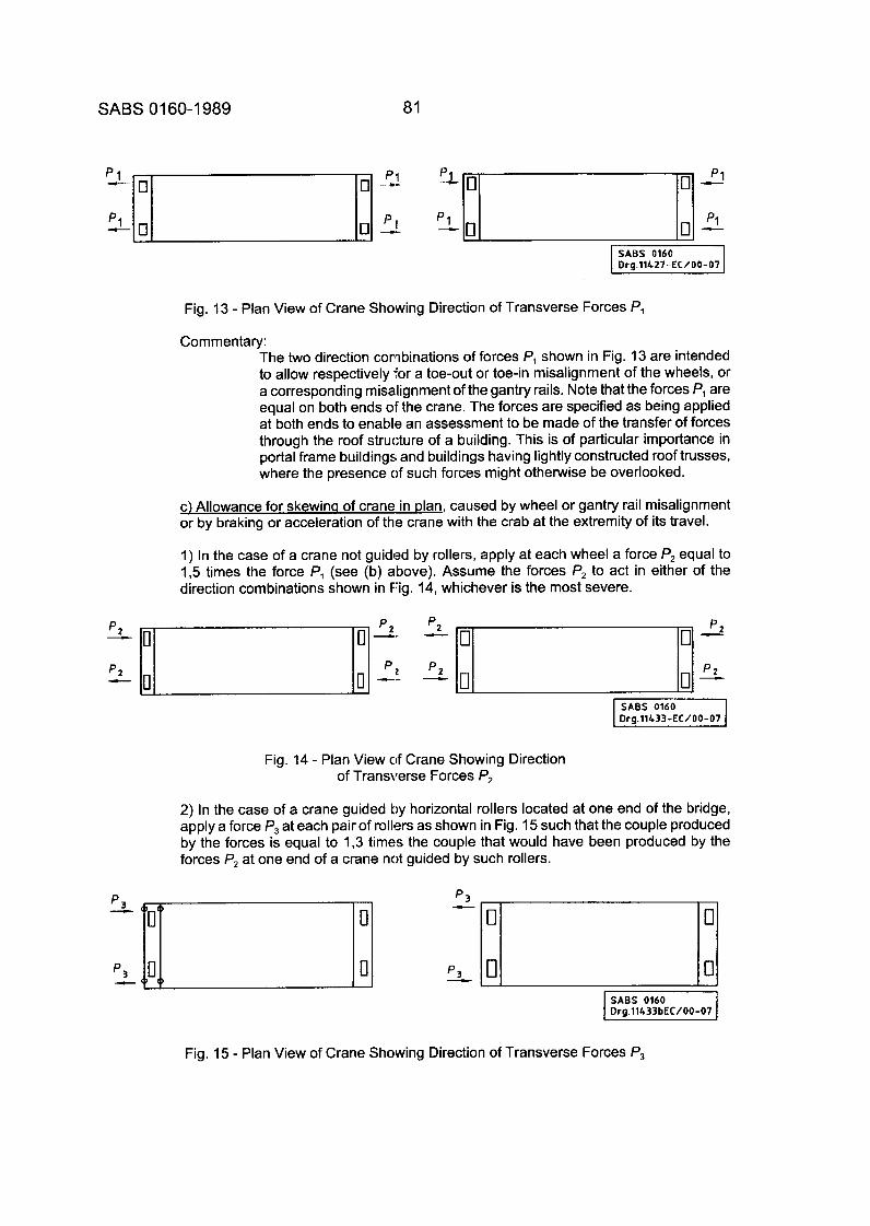
SABS 01 60-1 989 81
Fig. 13 - Plan View of Crane Showing Direction of Transverse Forces P,
Commentary: The two direction combinations of forces P, shown in Fig. 13 are intended to allow respectively for a toe-out or toe-in misalignment of the wheels, or a corresponding misalignment of the gantry rails. Note that the forces P, are equal on both ends of the crane. The forces are specified as being applied at both ends to enable an assessment to be made of the transfer of forces through the roof structure of a building. This is of particular importance in portal frame buildings and buildings having lightly constructed roof trusses, where the presence of such forces might otherwise be overlooked.
c) Allowance for skewinq of crane in plan, caused by wheel or gantry rail misalignment or by braking or acceleration of the crane with the crab at the extremity of its travel.
1) In the case of a crane not guided by rollers, apply at each wheel a force P2 equal to 1,5 times the force P, (see (b) above). Assume the forces P2 to act in either of the direction combinations shown in Fig. 14, whichever is the most severe.
SABS 0160 I Dra.ll&33-EC/00-07
Fig. 14 - Plan View of Crane Showing Direction of Transverse Forces P2
2) In the case of a crane guided by horizontal rollers located at one end of the bridge, apply a force P3 at each pair of rollers as shown in Fig. 15 such that the couple produced by the forces is equal to 1,3 times the couple that would have been produced by the forces P2 at one end of a crane not guided by such rollers.
I SABS 0160 I Drg.ll433bEC/00-07
Fig. 15 - Plan View of Crane Showing Direction of Transverse Forces P3
SABS 01 60-1 989 (As amended 1993)
82
5.7.5
5.7.6
5.7.7
5.7.8
5.7.9 Amdt 3, Oct. 1993
5.8
5.8.1
Commentary: The forces imposed by guide rollers are difficult to determine accurately but are known to be severe. This subsection makes provision, albeitempirically, for the action of guide rollers and is intended to ensure that gantry rails, their fixings, and the lateral support of the girders, are adequately catered for in the design.
The reason for relating the forces P3 to a couple and not directly to forces f2 is that the forces P3 depend upon the spacing of the guide rollers, the spacing of the wheels, and the number of wheels per end carriage, and therefore a direct relationship could not have been presented in a simple form.
Horizontal Lonqitudinal Force. Take the horizontal force imposed bya crane on each line of rails, acting longitudinally in the direction of travel and caused by acceleration or braking, to be 0,lO times the sum of the maximum static wheel loads on that line of rails.
Forces on End Stow. Take the horizontal force imposed on each end stop by a crane in the direction of travel to be the lesser of the following:
a) A force equal to the combined weight of the crane bridge and crab; b) a force calculated on the assumption that the crane strikes the end stop while travelling at its full rated speed, taking into account the resilience of the end stops and crane buffers.
NOTE: In (a) and (b) above, the weight of the load carried by the crane may be ignored unless it is restrained in a horizontal direction as in a mast or claw crane.
Position of Crane and Crab. In determining the crane loads set out in 5.7.4-5.7.6, assume the magnitude of the load lifted by a crane (up to its rated capacity), the position of the crab on the crane bridge, and the position of the crane on the gantry, to be such as will produce the most adverse effect upon the building or part of the building being designed.
More than One Crane in a Buildinq. Where more than one crane is to operate in a building, regardless of the number of bays, take the total forces imposed by such cranes to be as follows:
Static wheel loads from all cranes
Allowance for impact as given in 5.7.3 from any two cranes
Horizontal forces as given in any one of 5.7.4(a), 5.7.4(b), and 5.7.5
Horizontal forces as given in either of 5.7.4(c) or 5.7.6
Combination of Crane Lateral Forces and Wind Load. Where the effects of wind are to be considered in combination with the horizontal forces as given in any one of 5.7.4 - 5.7.6, then 0,5 times the nominal crane loads shall be taken as acting concurrently with the nominal wind load.
from any two cranes
from any one crane
OTHER LOADS
Provision for ImDact and Vibration. Ensure that where loads (arising from machinery runways, and other plant producing significant dynamic effects) are supported by or communicated to the framework, allowance is made for these dynamic loadings.
83 SABS 01 60-1 989
5.8.2 Liftina and Handlina Eauimnent. Where lifting or handling equipment, including forklift trucks and trolleys for heavy loads or cranes, is intended to be or is likely to be placed on any floor of a building and would result in loads in excess of those set out in 5.4.1 or 5.4.2 being imposed on any area of slab or on any beam, make provision in the design of the members concerned for the resultant maximum concentrated load or loads. Show in the documentation such maximum concentrated load or loads for which the members have been designed.
5.8.3
5.8.4
5.8.5
6.
6.1
6.1.1
Lateral and UDlift Forces
a) Basement walls. etc. In the design of basement walls and other similar members below ground level, due allowance must be made for the following forces:
1) The lateral force applied by adjacent soil; 2) fixed or moving loads on the surface of the adjacent soil; and 3) hydraulic force.
b) Basement floors, etc. In the design of basement floors and other similar members below ground level and below the level of a free water surface, due allowance must be made for upward hydraulic forces.
Inertia Swav Forces
a) Design all grandstands to resist the following inertia sway forces applied as indicated below to each row of seats or eac:h row of standing accommodation, as applicable:
300 N/m parallel to each row, ancl 150 N/m normal to each row.
b) Where, because of the occupancy of any building other than a grandstand, the activities within such building are liable to produce inertia effects, the designer must give consideration to such forces in the design process.
Ceilinas. Skvliahts and Similar Structures. Give consideration to the loads likely to be supported by joists and hangers for ceilings, ribs or skylights, frames, and coverings of ceiling access hatches, and any similar structures. Such loads can be derived from materials or workmen during construction and maintenance, and from electrical fittings, air-conditioning ducting and other services.
IN-SITU LOAD TESTING OF BUILDINGS AND BUILDING ELEMENTS
GENERAL
TvDes of Full Scale Load Tests. Full scale load tests fall into three main categories:
a) Tests, as provided for in 3.1.2, which are used as an aid to the design of a structure or series of structures yet to be built. b) Tests undertaken to monitor the quality or performance characteristics of serially produced buildings or components. c) In-situ tests applied to a specific building, a set of buildings, or parts of buildings, completed or under construction, in order to assess whether they are in accordance with the basic standards of safety or serviceability (or both) inherent in the national building regulations and the associated codes of practice, either because of alleged or known inadequacies in design, construction or materials, or because of an intended extension of or change in use, or because of possible impairment of load-bearing capacity as a result of fire, corrosion, or similar agencies.
Commentary: In-situ load testing is an aid to the assessment of the fitness of a building or of part of a building to support a specified set of loads within a prescribed
SABS 01 60-1 989 84
6.1.2
6.2
6.3
6.3.1
set of criteria. It is an adjunct to and not a substitute for engineering analysis or the exercise of competent professional judgement. This should be borne in mind in the planning, execution and interpretation of the results of load tests.
Load testing should normally not be undertaken until alternative avenues of investigation such as calculation, measurement, non-destructive material tests, core drilling and testing, etc., have been found insufficient. Load testing should be preceded by a thorough analysis of the nature and extent of the problem so that the objectives of the test or tests can be defined in detail and testing planned accordingly.
Tests of category 6.1 .l(a) are usually applied to specially constructed assemblies and are more in the nature of development or quasi-research activities, and each individual case should be treated on its merits by the designer or by the competent research or testing authority (or by both). Tests of category 6.1 . l (b) are part of the quality control specification for a contract and may therefore generally fall outside the scope of this code of practice.
Tests of category 6.1 . I (c) are the primary concern of this section, although some of its principles may also apply to tests of categories (a) and (b). Furthermore, the section is mainly concerned with tests on suspended floor and roof constructions which are the cases most commonly encountered and which are covered in the structural design codes for various building materials.
Probably the most significant difference between the three categories of load test is that, in general, the tests of categories (a) and (b) can be deliberately continued to failure to give a direct measure of the safety reserves of the structure, whereas in a category (c) test, the objective is to assess whether the building will support the service loads with an adequate margin of safety but without so overloading it as to cause serious damage or collapse since, if the structure is found to be satisfactory, it must still be capable of being placed in service after the test.
Planninq. The competent authority (see also 6.2) will plan, execute and evaluate a load test or load tests in accordance with the principles and guidelines contained in Section 6, where it is considered necessary to carry out such test or tests on a building or part of a building for any of the following reasons:
a) Doubts about the adequacy of the design or construction of an existing building or one that is under construction; b) damage or deterioration occasioned by fire or other agencies; c) changed loading conditions.
TESTING AUTHORITY. Ensure that the load test is designed, supervised and certified by a competent authority acting, whenever possible, in collaboration with the designer to ensure that the test effectively deals with those aspects of the construction that are in doubt.
TEST PROCEDURES
NOTE: Refer also to A-2(p), (q), and (r) of Appendix A.
Planninq. Ensure that at the planning stage of the test, there is, as far as possible, agreement between the parties concerned in regard to the following aspects:
a) The exact location, number and extent of the part(s) of the structure to be tested. (This will depend on the extent of the investigation.)
85 SABS 01 60-1 989
b) The test procedure to be adopted, including the following:
6.3.2
6.3.3
'I) The various stages of loading and unloading, including making up for any part of the self-weight which may still be missing in a partially completed structure; 2) the levels of loading at each stage; 3) the allowances or procedures to be adopted to cater for lateral interaction or load transfer between the loaded and adjacent unloaded parts of the structure or for loads transferred to non-structural elements, or both; 4) the duration of each stage of loading and unloading, having regard to the creep characteristics of the materials of construction involved and the short-term or long-term nature of the service loads being simulated; 5) the method of application of the load, having regard to the nature of the service load being simulated; 6) the response parameters to be measured, such as deflection, rotation, strain, or crack formation, and the positions and rnethods of measurement; 7) the possible influence of, and methods of allowing for, the external environmental factors (e.g. moisture or temperature changes) which may be in force during the test.
c) The criteria against which the results of the test and therefore the acceptability of the structure will be judged.
Conductina of Tests
a) Where the elements and materials concerned are designed in accordance with a specific code of practice and such code prescribes the load testing procedures and interpretations for such elements and materials, the competent authority must ensure that procedures and interpretations are carried out in accordance with such prescriptions.
b) Where the elements and materials concerned are not designed as set out in (a) above, follow the planning procedure as given in 6.3.1.
Test Precautions
a) Ensure that the condition of the structure and its materials (e.g. presence of floor screeds, maturity of concrete) is similar, within practical limits, to the minimum conditions assumed in the design. b) Adopt a method of loading that will ensure that the error in the applied load does not exceed 5 % of the applied load under service load conditions or 2 % of the maximum applied load in the overload test, whichever is the greater. c) Adopt methods of measuring the response of the structure that have an inherent accuracy of at least k 5 % of the maximum value expected in the test. d) Ensure that measurements of the deflection of members allow for settlement or elastic deformation of the supports of the members. e) Ensure that adequate safety precautions are taken to prevent injury to persons and to avoid damage to property during the test, especially with regard to the possibility of collapse of the element under test.
Commentary: When tests are conducted, attention should be given to the following:
a) The loading should preferably be applied in a sufficient number of increments (at least four) to enable a graph of load versus response (generally deflection) to be plotted during the test so that discontinuities or non-linearity in behaviour can be detected. b) For loads other than short-term transient loads (e.g. wind), creep behaviour should be allowed for by maintaining each increment of load until the response (deformation) has stabilized. The deformation may be considered to have stabilized when the increase in deformation under constant load during a given time interval (e.g. 5 min, or not more than one-quarter of the total time for which the load increment is maintained)
SABS 01 60-1 989 (As amended 1993)
86
Amdt 3, Oct. 1993
does not exceed 15 % of the increase in deformation in the preceding (equal) time increment at the same load. Generally, each increment of load should be maintained for at least 30 min . c) Unloading may be done in one step but more useful information can often be obtained if unloading is done in step-wise fashion, using the same incremental levels as for loading. Measurements of residual deformation after unloading should continue until the response has stabilized. d) Before the commencement of the loading test proper, a load to compensate for the effect of that portion (if any) of the self-weight load not already present in the assembly should be applied and maintained until all testing has been completed. The test proper should not commence until the deformation under the compensating load has stabilized. e) To allow for deformations of the structure and errors in measurement caused by temperature or other environmental changes, it is often advantageous, especially where the test extends over one or more days, to carry out a preliminary "dry run" during which no loads are applied but deformations are measured over a period of time corresponding to that over which the test will take place. If weather conditions, which should be monitored, remain reasonably stable, then the deformations obtained in the dry run may be used for correcting the deformations measured during the loading test proper. f) Lateral interaction or load sharing should be allowed for by loading a sufficient width of slab or panel or number of interconnected beams or trusses to ensure that all elements which are effectively interactive with the element under test are loaded. This may be determined by analysis in some cases; in others, the interactive width or number of elements may be determined by a preliminary load-sharing test up to a lower level of loading (not more than the characteristic or service load). For example, in such a test, the selected beam or strip of a one-way slab is loaded and its (midspan) deformation and those at the corresponding points of the potentially inter-acting beams or strips of slab on either side are measured. All beams or strips of slab that contribute more than 2,5 % to the sum of the deformations of the loaded and interacting elements are regarded as being effectively interactive.
For wide one-way spanning slabs, such an analysis may be dispensed with if a width of slab extending at least 1,5 times the span on either side of the portion under investigation is loaded in the test. For ribbed floors and similar constructions, it may sometimes be possible to separate a narrower test section from the adjacent floor by cutting. For two-way spanning floor panels, it will generally be necessary to load the whole panel. The number of one-way or two- way spans to be loaded will depend on whether the concern is with positive or negative moment behaviour (or both), shear strength, etc. Where non-load-bearing elements (such as partitions) with significant load-bearing properties are present, these may have to be removed or cut free of slabs to ensure that they do not influence the test. g) For checking the serviceability of the structure under working load conditions, the applied test load(s) should normally be the nominal value(s) of the imposed loading, i.e. the total load acting in the test is given by:
1,0 G, + 1,0 Q,
where
G, = nominal self-weight
0, = nominal imposed load
The load should be maintained until the response has been stabilized. At this stage it may be advantageous to unload the structure and repeat the
87 SABS 01 60-1 989
loading procedure to allow for "bedding in" of the structure and instrumentation and to provide a check on observational techniques before proceeding with the overload test for structural safety. h) For assessing the safety (ultimate strength) of the structure, the load levels should be sufficiently in excess of the nominal values to provide a reliable indication of the overload behaviour, but not so large as to be likely to cause failure of an acceptable structure. For example, in limit-state design terms, the total load appropriate for the test might reasonably be about 0,85 times the factored loads used in design for the ultimate limit state. On this basis, it is suggested that in the absence of other specific prescriptions, a maximum total load of 1,2 G, + 1,4 Q, be used during the test, to ensure safety. These values may need modification to allow for duration of load effects with materials whose strength is highly time dependent. The values should also be adjusted according to whether a single test is to serve as the basis for assessing a number of nominally similar structures or only the structure being tested. The load should be maintained until stabilization of deformation has occurred. i) The criteria for assessing compliance with the test for serviceability at working loads should normally be the design limits for deflection, deformation or cracking under service loads, reduced as may be necessary to allow for any part of the loading effects or time effects not covered by the test measurements. A distinction is necessary between pre-existing cracks or deformations (which may have led to the need for a test) and those arising or extending during the test. j) The structure under test may be deemed to have failed the test for safety or ultimate strength if one or more of the following conditions are attained:
1) The structure collapses or shows signs of distress or instability indicating that collapse is imminent. 2) The maximum deflection exceeds span/50. 3) Cracking or other local damage spreads significantly under constant load. 4) The increase of deformation under constant load that occurs during each of three successive equal time intervals shows no decrease. The duration of the intervals should be sufficient to enable the increments in deformation to be measured with sufficient accuracyfor a valid comparison to be made. 5) The recovery of deformation after removal of the test load (after allowing for stabilization to occur) is less than about 75 ?40 of the maximum deformation during the test. (This value may be increased to 85 % for metal structures, decreased to 70 % for timber structures and decreased to 60 % for plastics structures.) 6) The residual (permanent) deformation or cracking (under dead load only) arising from the test exceeds the values permitted in design for full service loading.
k) When tests are performed on very stiff structures, the deformations may be so small that they cannot be reliably determined and the criteria in (j)(4) and (5) above cannot reasonably be applied. I) When structures are tested that are likely to exhibit brittle failures or instability failures, the assessment of performance becomes difficult since the response measurements may give no indication of the imminence of fai I u re.
SABS 01 60-1 989 88 (As amended 1990 and 1993)
A- 1
A-2
Amdt 3, Oct. 1993
APPENDIX A. APPLICABLE PUBLICATIONS (This appendix does not form part of the provisions of the code)
Reference is made to the latest issues of the following standards:
ANSI A58.1 Design loads for buildings and other structures, minimum
ATC 3-06
IS0 2631
Applied Technology Council, 1978
Evaluation of human exposure to wholebody vibration
IS04356 Bases for the design of structures. Deformations of buildings at the serviceability limit states
IS0 8930 General principles on reliability for structures - List of equivalent terms
SABS 0100 The structural use of concrete
SABS 0137 The installation of glazing materials in buildings
SABS 0161 The design of foundations for buildings
SABS 01 62 The structural use of steel
SABS 0163 The design of timber structures
SABS 0164 Structural use of masonry
SABS 0400 The application of the National Building Regulations
The information contained in this code of practice is considered adequate for the design of the majority of buildings. For those buildings, structures or elements that are not adequately covered or where special conditions apply or where additional information is desired by the designer, the following publications should be consulted:
- Milford, RV 'Annual maximum wind speeds for South Africa', published in The civil enaineer in South Africa, January 1987.
a) NBRl Information Sheet WBOU 2-41, 'Wind flows around and pressures on buildings', published by the National Building Research Institute, CSIR, Pretoria, 1978. b) Weather Bureau Report WB 38, 'Climate of South Africa, Part 12, Surface winds', published by the Weather Bureau, Department of Environment Affairs, Pretoria, 1975. c) NEWBERRY and EATON, Wind loadina handbook, published by the Building Research Establishment, HMSO, London, 1974. d) The modern desiqn of wind sensitive structures, published by the Construction Industry Research and Information Association, London, 1971. (Wind characteristics, along-wind response, vortex excitation, galloping, flutter.) e) Commentaries on Part 4 of the national buildinq code of Canada 1977, published by the National Research Council of Canada, 1977. (Along-wind response: method and charts, vortex excitation, accelerations.) f) DAVENPORT, AG, Gust loadinq factors, published by the American Society of Civil Engineers, Structural Division, Journal, Vol. 93, June 1967. (Along-wind response: method and charts.) g) Australian Standard 11 70, Part2, 1975, 'SAA loading code: "Wind forces"', published by the Standards Association of Australia. (Along- and cross-wind response discussed in an appendix.)
89 SABS 01 60-1 989 (As amended 1990)
h) VICKERY, BJ, 'On the reliability of gust factors', Civil Enaineerina Transactions of the Institute of Engineers, Australia, L'ol. CE 13, No. 1, April, 1971. (Along-wind response: method and charts.) i) SIMIU, E and SCANLEN, RH, Wind effects on structures - an introduction to wind enqineering, published by John Wiley, New York, 1978. (Wind characteristics, along-wind response: method and charts, vortex excitation, galloping, flutter, wind-induced discomfort in and around buildings.) j) SIMIU, E and LOZIER, DW, The buffetina of tall structures bv strona winds, NBS Building Science Series 74, 1975, published by the National Bureau of Standards, US Dept. of Commerce, Washington, 1975. (Along-wind response: method and charts, corn pu ter program. ) k) PINFOLD, GM, Reinforced concrete chimnevs and towers, published by Viewpoint Publications, London, 1975. (Dynamic wind forces on chimneys, vortex excitation.) I) HOUGHTON, EL, and CARRUTHERS, NB, Wind forces on buildinas and structures: an introduction, published by Edward Arnold, London, 1976. (All aspectsofwind loading.) m) AYNSLEY RM, et al, Architectural aerodvnamics, published by Applied Science Publishers, London, 1977. (All aspects of wind loading and environmental effects of wind.) n) CHASTEAU, VAL, 'Wind effects on structures', published in The civil enaineer in South Africa, commenced in February, 1971 and concluded in March, 1971 issues. (Analysis for thunderstorm winds.) 0) DAVENPORT, AG and NOVAK, M, Vibrations of structures induced bv wind: Shock and vibration handbook, edited by Harris and Crede, published by McGraw-Hill, 1976. p) 'General recommendation for loading tests of load-bearing structures in situ', preliminary recommendations of the 20-TBS Committee of RILEM, published in Materials and structures, No. 53, September - October 1976. q) MENZIES, JB, 'Load testing of concrete building structures', published in The structural engineer, Vol 56A, December 1978. r) BARES, R and FITZSIMONS, N, 'Load tests of building structures', published by the American Society of Civil Engineers, Structural Division, Journal, Vol. 101, No. ST5, May 1975. s ) Earthquake enaineerinq, co-ordinating editor RL WIEGEL, published by Prentice Hall, USA. t) Geological Survey - Seismological Series, compiled by FERNANDEZ, LM and GUSMAN, JA: No. 9 'Seismic history of Southern Africa' No. 10 'Earthquake hazards in Southern Africa'. U) Weather Bureau Report WB 36, 'Climate of South Africa, Part 2, Extreme values of rainfall, temperature and wind for selected return periods', published by the Weather Bureau, Department of Environment Affairs, Pretoria, 1974. v) SCHWARTZ, HJ and CULLIGAN, PT, 'Roof drainage of large buildings in South Africa'. The civil enqineer in South Africa, August 1976. w) Hydrological Research Unit, Desian flood determination in South Africa, Report No. 1/72, University of the Witwatersrand, Johannesburg, 1972. x) CULLIGAN, PT, Compilation of a manual for the desian of roof drainaae svstems, M.Sc. Dissertation, University of the Witwatersrand, Johannesburg. y) Weather Bureau Report WB 20, 'Climate of South Africa, Part 2, Rainfall statistics'; published by the Weather Bureau, Department of Transport, Pretoria. z) DOWRICK, DJ, 'Earthquake resistant design', Wiley, 1977. aa) DOWRICK, DJ, 'Earthquake resistant design. A manual for engineers and architects', Wiley - lnterscience Publication, John Wiley & Sons, New York, 1977. bb) FERNANDEZ, LM and SHAPIRO, A, Maps of the probabilities of earthquake occurrence in South Africa. Geological Survey, Pretoria. (1989, In press). cc) SHAPIRO, A and FERNANDEZ, LM, Probabilities of exceedance for prescribed peak ground accelerations (PGA) at selected Southern Africa locations. Report No. 1987-01 00, Geological Survey, Pretoria, 1987.
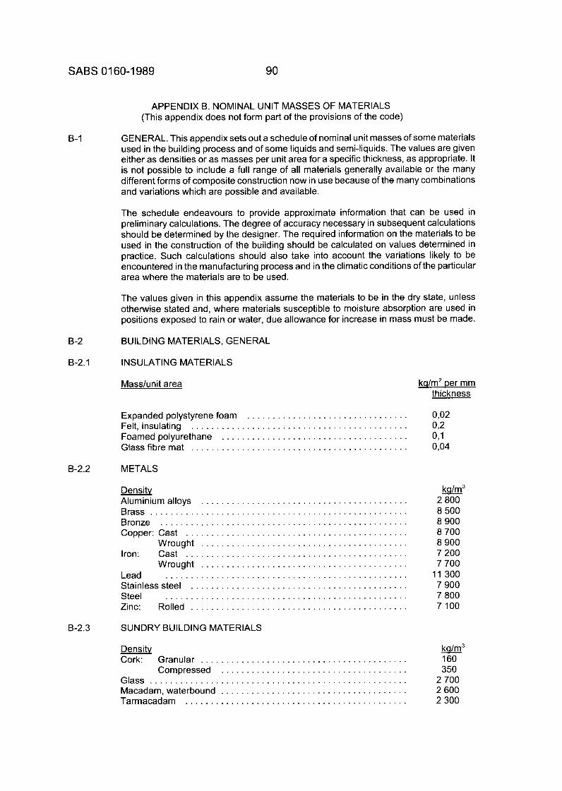
SABS 01 60-1 989 90
B-1
APPENDIX B. NOMINAL UNIT MASSES OF MATERIALS (This appendix does not form part of the provisions of the code)
GENERAL. This appendix sets out a schedule of nominal unit masses of some materials used in the building process and of some liquids and semi-liquids. The values are given either as densities or as masses per unit area for a specific thickness, as appropriate. It is not possible to include a full range of all materials generally available or the many different forms of composite construction now in use because of the many combinations and variations which are possible and available.
The schedule endeavours to provide approximate information that can be used in preliminary calculations. The degree of accuracy necessary in subsequent calculations should be determined by the designer. The required information on the materials to be used in the construction of the building should be calculated on values determined in practice. Such calculations should also take into account the variations likely to be encountered in the manufacturing process and in the climatic conditions of the particular area where the materials are to be used.
The values given in this appendix assume the materials to be in the dry state, unless otherwise stated and, where materials susceptible to moisture absorption are used in positions exposed to rain or water, due allowance for increase in mass must be made.
B-2 B U I L D I N G MAT ER I ALS , G E N E RAL
B-2.1 INSULATING MATERIALS
Masshnit area k q h 2 per mm thickness
Expanded polystyrene foam . . . . . . . . . . . . . . . . . . . . . . . . . . . . . . . . 0,02 Felt, insulating . . . . . . . . . . . . . . . . . . . . . . . . . . . . . . . . . . . . . . . . . . . 0 2 Foamed polyurethane . . . . . . . . . . . . . . . . . . . . . . . . . . . . . . . . . . . . . 0,1 Glassfibremat . . . . . . . . . . . . . . . . . . . . . . . . . . . . . . . . . . . . . . . . . . . 0,04
B-2.2 METALS
Densitv Aluminium alloys . . . . . . . . . . . . . . . . . . . . . . . . . . . . . . . . . . . . . . . . . Brass . . . . . . . . . . . . . . . . . . . . . . . . . . . . . . . . . . . . . . . . . . . . . . Bronze . . . . . . . . . . . . . . . . . . . . . . . . . . . . . . . . . . . . . . . . . . . . . . . . . Copper: Cast . . . . . . . . . . . . . . . . . . . . . . . . . . . . . .
Wrought . . . . . . . . . . . . . . . . . . . . . . . . . . . . . . . . . . . . . . . . . Iron: Cast . . . . . . . . . . . . . . . . . . . . . . . . . . . . . . . . . . . . . . . .
Wrought . . . . . . . . . . . . . . . . . . . . . . . . . . . . . . . . . . . . . . . . . Lead . . . . . . . . . . . . . . . . . . . . . . . . . . . . . . . . . . . . . . . . . . . . . . . . Stainless steel . . . . . . . . . . . . . . . . . . . . . . . . . . . . . . Steel . . . . . . . . . . . . . . . . . . . . . . . . . . . . . . . . . . . . . . . . . . . . Zinc: Rolled . . . . . . . . . . . . . . . . . . . . . . . . . . . . . . . . . . . . . . . . . . .
8-2.3 SUNDRY BUILDING MATERIALS
k n / m 3
2 800 8 500 8 900 8 700 8 900 7 200 7 700
11 300 7 900 7 800 7 100
Density U 3
Cork: Granular . . . . . . . . . . . . . . . . . . . . . . . . . . . . . . . . . . . . . . . . . 160 Compressed . . . . . . . . . . . . . . . . . . . . . . . . . . . . . . . . . . . . . 350
Glass 2 700 Macadarn,waterbound . . . . . . . . . . . . . . . . . . . . . . . . . . . . . . . . . . . . . 2 600 Tarmacadam . . . . . . . . . . . . . . . . . . . . . . . . . . . . . . . . . . . . . . . . . . . . 2 300
. . . . . . . . . . . . . . . . . . . . . . . . . . . . . . . . . . . . . . . . . . . . . . . . . . .
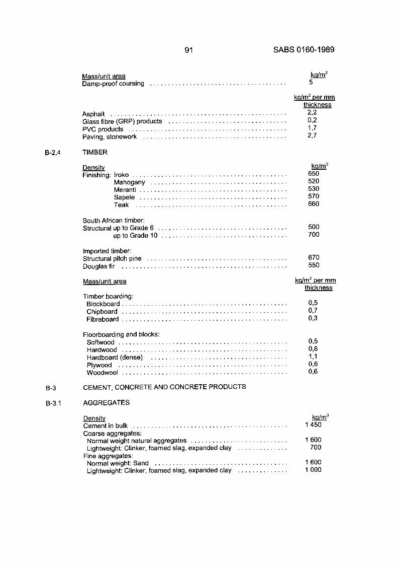
91 SABS 01 60-1 989
8-2.4
8-3
8-3.1
Mass/u n i t area Damp-proof coursing . . . . . . . . . . . . . . . . . . . . . . . . . . . . . . . . . . . . . .
Asphalt . . . . . . . . . . . . . . . . . . . . . . . . . . . . . . . . . . . . . . . . . . . . . . .
PVCproducts . . . . . . . . . . . . . . . . . . . . . . . . . . . . . . . . . . . . . . . . . . Glass fibre (GRP) products . . . . . . . . . . . . . . . . . . . . . . . . . . . . . . .
Paving, stonework . . . . . . . . . . . . . . . . . . . . . . . . . . . . . . . . . . . . . .
TIMBER
Densitv Finishing: lroko . . . . . . . . . . . . . . . . . . . . . . . . . . . . . . . . . . . . . . . . . . .
Mahogany . . . . . . . . . . . . . . . . . . . . . . . . . . . . . . . . . . . . . . Meranti . . . . . . . . . . . . . . . . . . . . . . . . . . . . . . . . . . . . . . . . . Sapele . . . . . . . . . . . . . . . . . . . . . . . . . . . . . . . . . . . . . . . . . Teak . . . . . . . . . . . . . . . . . . . . . . . . . . . . . . . . . . . . . . . . . .
South African timber: Structural up to Grade 6 . . . . . . . . . . . . . . . . . . . . . . . . . . . . . . . . . . . .
uptoGrade10 . . . . . . . . . . . . . . . . . . . . . . . . . . . . . . . . . . .
Imported timber:
Douglasfir . . . . . . . . . . . . . . . . . . . . . . . . . . . . . . . . . . . . . . . . . . . . . . Structural pitch pine . . . . . . . . . . . . . . . . . . . . . . . . . . . . . . . . . . . . . . .
Masslunit area
Timber boarding: Blockboard . . . . . . . . . . . . . . . . . . . . . . . . . . . . . . . . . . . . . . . . . . . . . . Chipboard . . . . . . . . . . . . . . . . . . . . . . . . . . . . . . . . . . . . . . . . . . . . . . Fibreboard . . . . . . . . . . . . . . . . . . . . . . . . . . . . . . . . . . . . . . . . . . . . . .
Floorboarding and blocks: Softwood . . . . . . . . . . . . . . . . . . . . . . . . . . . . . . . . . . . . . . . . . . . . . . . Hardwood . . . . . . . . . . . . . . . . . . . . . . . . . . . . . . . . . . . . . . . . . . . . . .
Plywood . . . . . . . . . . . . . . . . . . . . . . . . . . . . . . . . . . . . . . . . . . . . . . . Woodwool . . . . . . . . . . . . . . . . . . . . . . . . . . . . . . . . . . . . . . . . . . . . . .
Hardboard (dense) . . . . . . . . . . . . . . . . . . . . . . . . . . . . . . . . . . . . . .
CEMENT, CONCRETE AND CONCRETE PRODUCTS
AGGREGATES
k n / m 2
5
kdm2 per mm
2 2 0 2 177 2.7
thickness
k a / m 3
650 520 530 570 660
500 700
670 550
kdm2 per mm thickness
Densitv k n / m 3
1450
1 600 700
. . . . . . . . . . . . . . . . . . . . . . . . . . . . . . . . . . . . . 1 600 Normal weight: Sand 1000
Cementin bulk . . . . . . . . . . . . . . . . . . . . . . . . . . . . . . . . . . . . . . . . . . . Coarse aggregates: Normal weight natural aggregates . . . . . . . . . . . . . . . . . . . . . . . . . . . Lightweight: Clinker, foamed slag, expanded clay
Lightweight: Clinker, foamed slag, expanded clay
. . . . . . . . . . . . . . Fine aggregates:
. . . . . . . . . . . . . .
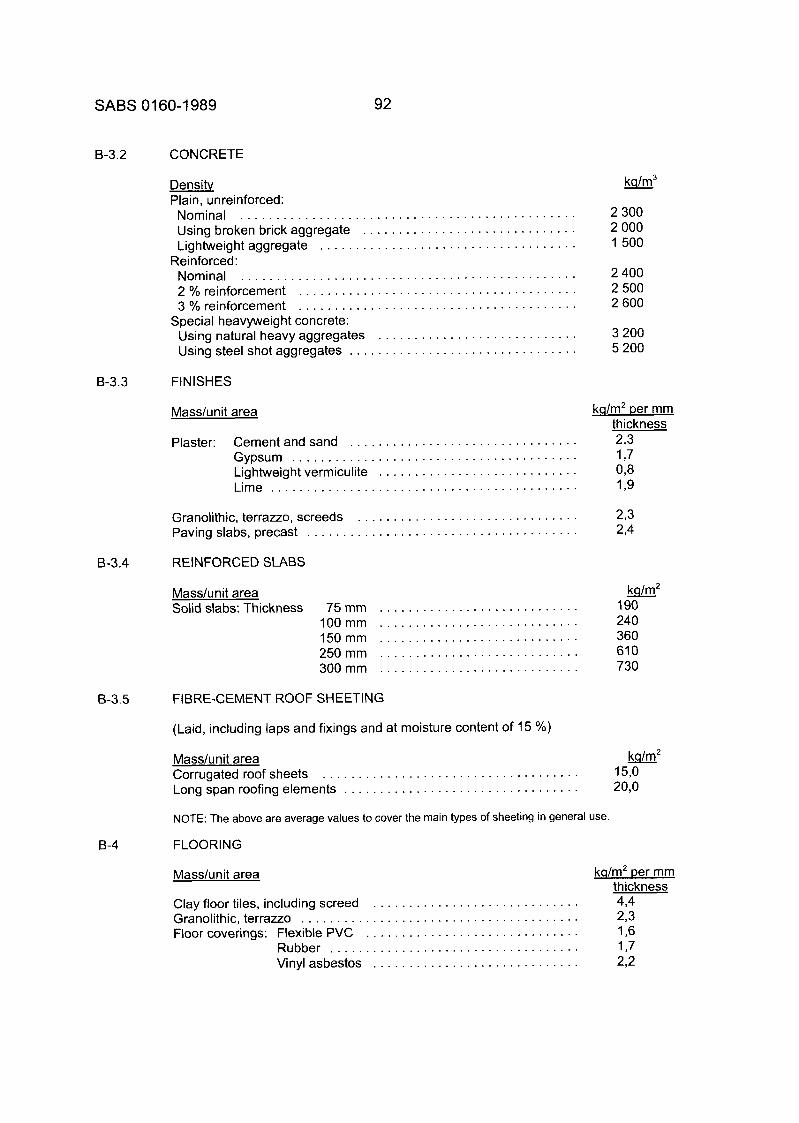
SABS 01 60-1 989 92
8-3.2 CONCRETE
Density Plain, unreinforced: Nominal . . . . . . . . . . . . . . . . . . . . . . . . . . . . . . . . . . . . . . . . . . . . . . . Using broken brick aggregate . . . . . . . . . . . . . . . . . . . . . . . . . . . . . . Lightweightaggregate . . . . . . . . . . . . . . . . . . . . . . . . . . . . . . . . . . . .
Nominal . . . . . . . . . . . . . . . . . . . . . . . . . . . . . . . . . . . . . . . . . . . . . . . 2 % reinforcement . . . . . . . . . . . . . . . . . . . . . . . . . . . . . . . . . . . . . . . 3 % reinforcement . . . . . . . . . . . . . . . . . . . . . . . . . . . . . . . . . . . . . . .
Reinforced:
Special heavyweight concrete: Using natural heavy aggregates . . . . . . . . . . . . . . . . . . . . . . . . . . . . Using steel shot aggregates . . . . . . . . . . . . . . . . . . . . . . . . . . . . . . . .
8-3.3 FINISHES
Mass/unit area
2 300 2 000 1500
2 400 2 500 2 600
3 200 5 200
kq/m2 per mm thickness 2 3
Gypsum 1,7 Lightweight vermiculite . . . . . . . . . . . . . . . . . . . . . . . . . . . . 0 3 Lime 1 3
Plaster: Cement and sand . . . . . . . . . . . . . . . . . . . . . . . . . . . . . . . . . . . . . . . . . . . . . . . . . . . . . . . . . . . . . . . . . . . . . . . .
. . . . . . . . . . . . . . . . . . . . . . . . . . . . . . . . . . . . . . . . . . .
Granolithic, terrazzo, screeds . . . . . . . . . . . . . . . . . . . . . . . . . . . . . . . 2,3 Paving slabs, precast . . . . . . . . . . . . . . . . . . . . . . . . . . . . . . . . . . . . . . 2,4
8-3.4 REINFORCED SLABS
Mass/unit area ks/m2 190
100mm 240 150mm 360 250mm 610 300mm 730
Solid slabs: Thickness 75 mm . . . . . . . . . . . . . . . . . . . . . . . . . . . . . . . . . . . . . . . . . . . . . . . . . . . . . . . . . . . . . . . . . . . . . . . . . . . . . . . . . . . . . . . . . . . . . . . . . . . . . . . . . . . . . . . . . . . . . . . . . . . . . . . . . . . . . . . . . . . .
B-3.5 FIBRE-CEMENT ROOF SHEETING
8-4
(Laid, including laps and fixings and at moisture content of 15 %)
Masdunit area k n / m 2
Corrugated roof sheets . . . . . . . . . . . . . . . . . . . . . . . . . . . . . . . . . . . . Long span roofing elements . . . . . . . . . . . . . . . . . . . . . . . . . . . . . . . . .
150 20,o
NOTE: The above are average values to cover the main types of sheeting in general use.
FLOORING
Mass/u nit area kq/m2 per mm thickness
Clay floor tiles, including screed . . . . . . . . . . . . . . . . . . . . . . . . . . . . . 4,4 Granolithic, terrazzo . . . . . . . . . . . . . . . . . . . . . . . . . . . . . . . . . . . . . . . 2 3 Floor coverings: Flexible PVC . . . . . . . . . . . . . . . . . . . . . . . . . . . . . . 1,6
Rubber 1,7 Vinyl asbestos . . . . . . . . . . . . . . . . . . . . . . . . . . . . . 2 2
. . . . . . . . . . . . . . . . . . . . . . . . . . . . . . . . . . .
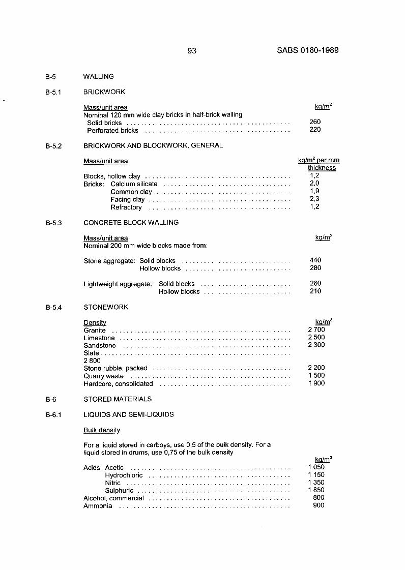
93 SABS 01 60-1 989
WALLING B-5
B-5.1
8-5.2
B-5.3
8-5.4
B -6
B-6.1
BRICKWORK
Mass/u n i t area Nominal 120 mm wide clay bricks in half-brick walling Solid bricks . . . . . . . . . . . . . . . . . . . . . . . . . . . . . . . . . . . . . . . . . . . Perforated bricks . . . . . . . . . . . . . . . . . . . . . . . . . . . . . . . . . . . . . .
BRICKWORK AND BLOCKWORK. GENERAL
Masshnit area
Blocks. hollow clay . . . . . . . . . . . . . . . . . . . . . . . . . . . . . . . . . . . . . . . . Bricks: Calcium silicate . . . . . . . . . . . . . . . . . . . . . . . . . . . . . . . . . . .
Commonclay . . . . . . . . . . . . . . . . . . . . . . . . . . . . . . . . . . . . . Facingclay . . . . . . . . . . . . . . . . . . . . . . . . . . . . . . . . . . . . . . . Refractory . . . . . . . . . . . . . . . . . . . . . . . . . . . . . . . . . . . . . . .
CONCRETE BLOCK WALLING
Mass/unit area Nominal 200 mm wide blocks made from:
Stone aggregate: Solid blocks . . . . . . . . . . . . . . . . . . . . . . . . . . . . . . Hollow blocks . . . . . . . . . . . . . . . . . . . . . . . . . . . . .
Lightweight aggregate: Solid blocks . . . . . . . . . . . . . . . . . . . . . . . . . Hollow blocks . . . . . . . . . . . . . . . . . . . . . . . .
STONEWORK
Densitv Granite . . . . . . . . . . . . . . . . . . . . . . . . . . . . . . . . . . . . . . . . . . . . . . . . . Limestone . . . . . . . . . . . . . . . . . . . . . . . . . . . . . . . . . . . . . . . . . . . . . . . Sandstone . . . . . . . . . . . . . . . . . . . . . . . . . . . . . . . . . . . . . . . . . . . . . . Slate . . . . . . . . . . . . . . . . . . . . . . . . . . . . . . . . . . . . . . . . . . . . . . . . . . . . 2 800 Stonerubble. packed . . . . . . . . . . . . . . . . . . . . . . . . . . . . . . . . . . . . . . Quarrywaste . . . . . . . . . . . . . . . . . . . . . . . . . . . . . . . . . . . . . . . . . . . . Hardcore. consolidated . . . . . . . . . . . . . . . . . . . . . . . . . . . . . . . . . . . .
STORED MATERIALS
LIQUIDS AND SEMI-LIQUIDS
Bulk densitv
For a liquid stored in carboys. use 0. 5 of the bulk density . For a liquid stored in drums. use 0. 75 of the bulk density
Acids: Acetic . . . . . . . . . . . . . . . . . . . . . . . . . . . . . . . . . . . . . . . . . . . . Hydrochloric . . . . . . . . . . . . . . . . . . . . . . . . . . . . . . . . . . . . . . . Nitric . . . . . . . . . . . . . . . . . . . . . . . . . . . . . . . . . . . . . . . . . . . . . Sulphuric . . . . . . . . . . . . . . . . . . . . . . . . . . . . . . . . . . . . . . . . . .
Alcohol. commercial . . . . . . . . . . . . . . . . . . . . . . . . . . . . . . . . . . . . . . . Ammonia . . . . . . . . . . . . . . . . . . . . . . . . . . . . . . . . . . . . . . . . . . . . . . .
260 220
440 280
260 210
k n / m 3
2700 2500 2300
2200 1500 1900
k a / m 3
1050 1150 1350 1850
800 900

SABS 01 60-1 989
Beer: Bulk . . . . . . . . . . . . . . . . . . . . . . . . . . . . . . . . . . . . . . . . . . . . . . 1 000 Bottlesin cases . . . . . . . . . . . . . . . . . . . . . . . . . . . . . . . . . . . . . 450 Barrels . . . . . . . . . . . . . . . . . . . . . . . . . . . . . . . . . . . . . . . . . . . . 550
Benzine . . . . . . . . . . . . . . . . . . . . . . . . . . . . . . . . . . . . . . . . . . . . . . . . . 900 Bitumen . . . . . . . . . . . . . . . . . . . . . . . . . . . . . . . . . . . . . . . . . . . . . . . . 1 400 Methylated spirits . . . . . . . . . . . . . . . . . . . . . . . . . . . . . . . . . . . . . . . . . 850 Linseedoil . . . . . . . . . . . . . . . . . . . . . . . . . . . . . . . . . . . . . . . . . . . . . . .
Milk . . . . . . . . . . . . . . . . . . . . . . . . . . . . . . . . . . . . . . . . . . . . . . . . . . 1050 900
Mineral oils: Naphtha . . . . . . . . . . . . . . . . . . . . . . . . . . . . . . . . . . . . . 750 Paraffin . . . . . . . . . . . . . . . . . . . . . . . . . . . . . . . . . . . . . . 800 Petrol . . . . . . . . . . . . . . . . . . . . . . . . . . . . . . . . . . . . . . . 700 Petroleum oil . . . . . . . . . . . . . . . . . . . . . . . . . . . . . . . . . 900
Pulp(wood) . . . . . . . . . . . . . . . . . . . . . . . . . . . . . . . . . . . . . . . . . . . . . 750
Turpentine . . . . . . . . . . . . . . . . . . . . . . . . . . . . . . . . . . . . . . . . . . . . . . 850 Tar,pitch . . . . . . . . . . . . . . . . . . . . . . . . . . . . . . . . . . . . . . . . . . . . . . . . 1200
Water: Fresh . . . . . . . . . . . . . . . . . . . . . . . . . . . . . . . . . . . . . . . . . . . . 1 000 Sea-water . . . . . . . . . . . . . . . . . . . . . . . . . . . . . . . . . . . . . . . . 1 050
Wine: Bulk . . . . . . . . . . . . . . . . . . . . . . . . . . . . . . . . . . . . . . . . . . . . . 1 000 Bottlesincases . . . . . . . . . . . . . . . . . . . . . . . . . . . . . . . . . . . . 600
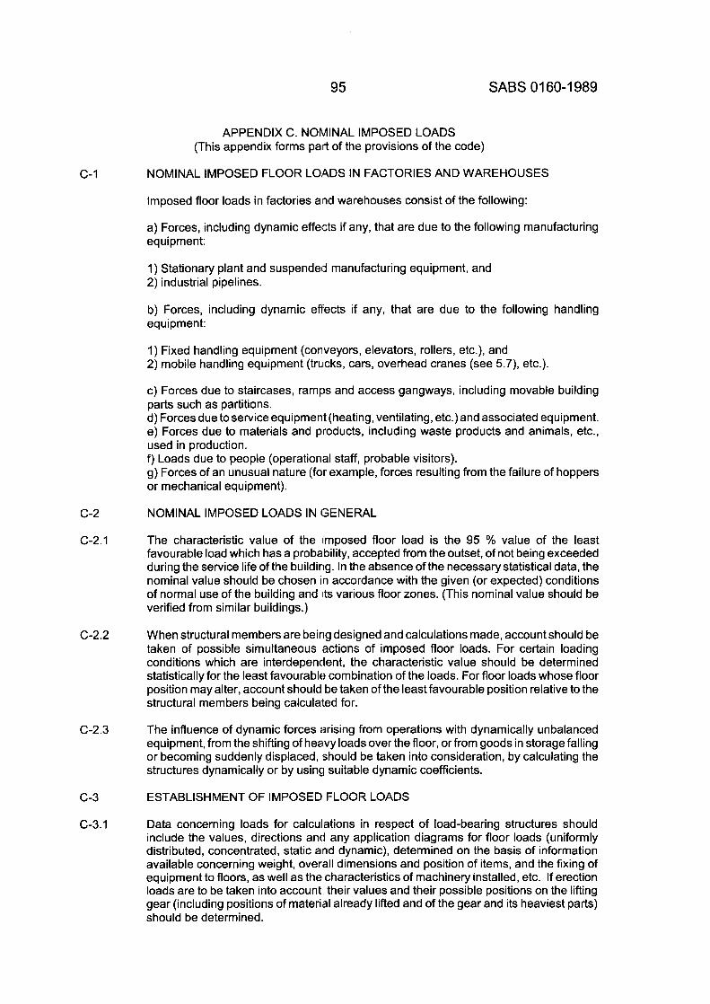
95 SABS 01 60-1 989
c- 1
c-2
c-2.1
c-2.2
C-2.3
c-3
C-3.1
APPENDIX C. NOMINAL IMPOSED LOADS (This appendix forms part of the provisions of the code)
NOMINAL IMPOSED FLOOR LOADS IN FACTORIES AND WAREHOUSES
Imposed floor loads in factories alnd warehouses consist of the following:
a) Forces, including dynamic effects if any, that are due to the following manufacturing equipment:
1 ) Stationary plant and suspended manufacturing equipment, and 2) industrial pipelines.
b) Forces, including dynamic effects if any, that are due to the following handling equipment:
1 ) Fixed handling equipment (conveyors, elevators, rollers, etc.), and 2) mobile handling equipment (trucks, cars, overhead cranes (see 5.7), etc.).
c) Forces due to staircases, ramps and access gangways, including movable building parts such as partitions. d) Forces due to service equipment (heating, ventilating, etc.) and associated equipment. e) Forces due to materials and products, including waste products and animals, etc., used in production. 9 Loads due to people (operational staff, probable visitors). g) Forces of an unusual nature (for example, forces resulting from the failure of hoppers or mechanical equipment).
NOMINAL IMPOSED LOADS IN GENERAL
The characteristic value of the imposed floor load is the 95 % value of the least favourable load which has a probability, accepted from the outset, of not being exceeded during the service life of the building. In the absence of the necessary statistical data, the nominal value should be chosen in accordance with the given (or expected) conditions of normal use of the building and Nits various floor zones. (This nominal value should be verified from similar buildings.)
When structural members are being designed and calculations made, account should be taken of possible simultaneous actions of imposed floor loads. For certain loading conditions which are interdependent, the characteristic value should be determined statistically for the least favourable combination of the loads. For floor loads whose floor position may alter, account should be taken of the least favourable position relative to the structural members being calculated for.
The influence of dynamic forces arising from operations with dynamically unbalanced equipment, from the shifting of heavy loads over the floor, or from goods in storage falling or becoming suddenly displaced, should be taken into consideration, by calculating the structures dynamically or by using suitable dynamic coefficients.
ESTABLISHMENT OF IMPOSED FLOOR LOADS
Data concerning loads for calculations in respect of load-bearing structures should include the values, directions and any application diagrams for floor loads (uniformly distributed, concentrated, static and dynamic), determined on the basis of information available concerning weight, overall dimensions and position of items, and the fixing of equipment to floors, as well as the characteristics of machinery installed, etc. If erection loads are to be taken into account, their values and their possible positions on the lifting gear (including positions of material already lifted and of the gear and its heaviest parts) should be determined.
SABS 01 60-1 989 96
The chief sources of the data referred to above are as follows:
C-3.2
c-3.3
c-3.4
c-3.5
C-3.6
c-3.7
a) Standards and catalogues of equipment; b) data supplied by the equipment suppliers; c) advice from experts responsible for the technicalside of the building being designed; d) data supplied by the users of the building.
When the nominal load from the weight of manufacturing plant is being determined, account should be taken of
a) the weight of the plant (including the weight of the drive, additional bearing devices, and insulation); b) the weight of the heaviest pieces under treatment or the weight of the products being processed (liquids, materials in bulk); c) the weight of gangways and working platforms; d) loads accruing from necessary maintenance or replacement of stationary plant.
The weight of the product being processed should be determined by using its maximum possible volume under normal operation in the plant.
When nominal loads due to handling equipment are being determined, the weight of the machine should be taken as its weight under working conditions (i.e. allowance should be made for the weight of fuel, power sources, etc.) and the load carried should be taken as equal to the nominal load-lifting capacity of the machine.
Nominal loads in garages depend on the weights of vehicles, probable service equipment, spare parts, etc., with provision for the values of possible loads on the vehicles depending on the types of vehicles and conditions of garage use.
Nominal loads in warehouses should be determined with regard to the types of materials stacked and the methods of storage. Account should be taken of the greatest volume of materials (the greatest number of stacked articles) located on the area of the floor under normal operational conditions of the warehouse, allowing for the densest stacking of materials and articles and the possible effect of the increase in density of some materials when stored for a long time (e.g. effects of the increase in moisture).
When loads on floor zones not occupied by stationary equipment and in warehouses are being defined, provision should be made for loads from mobile handling equipment and for the following loads:
a) Loads due to crowds of people possible during normal operation of the structure; b) loads due to materials and semi-finished products temporarily stored near the processing equipment (at intervals between machining operations or ready for transport to the warehouse); c) loads due to the weight of waste products, etc.
When stresses and deformation in buildings are being calculated, the actual floor loads may be replaced by simplified load diagrams of equivalent effect.
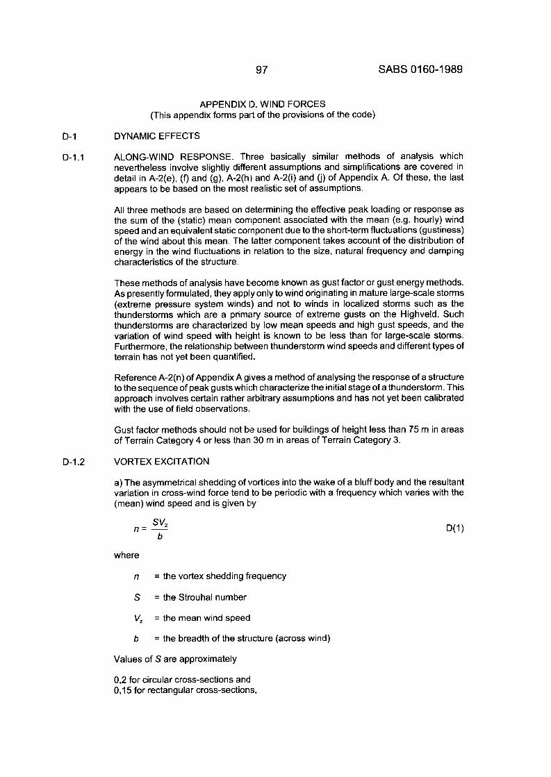
97 SABS 01 60-1 989
APPENDIX 13. WIND FORCES (This appendix forms part of the provisions of the code)
D-I DYNAMIC EFFECTS
D-I .I ALONG-WIND RESPONSE. Three basically similar methods of analysis which nevertheless involve slightly different assumptions and simplifications are covered in detail in A-2(e), (f) and (g), A-2(h) and A-2(i) and (j) of Appendix A. Of these, the last appears to be based on the most realistic set of assumptions.
All three methods are based on determining the effective peak loading or response as the sum of the (static) mean corriponent associated with the mean (e.g. hourly) wind speed and an equivalent static cornponent due to the short-term fluctuations (gustiness) of the wind about this mean. The latter component takes account of the distribution of energy in the wind fluctuations in relation to the size, natural frequency and damping characteristics of the structure.
These methods of analysis have become known as gust factor or gust energy methods. As presently formulated, they apply only to wind originating in mature large-scale storms (extreme pressure system winds) and not to winds in localized storms such as the thunderstorms which are a primary source of extreme gusts on the Highveld. Such thunderstorms are characterized by low mean speeds and high gust speeds, and the variation of wind speed with height is known to be less than for large-scale storms. Furthermore, the relationship between thunderstorm wind speeds and different types of terrain has not yet been quantified.
Reference A-2(n) of Appendix A gives a method of analysing the response of a structure to the sequence of peak gusts which characterize the initial stage of a thunderstorm. This approach involves certain rather arbitrary assumptions and has not yet been calibrated with the use of field observations.
Gust factor methods should not be used for buildings of height less than 75 m in areas of Terrain Category 4 or less than 30 m in areas of Terrain Category 3.
D-I .2 VORTEX EXCITATION
a) The asymmetrical shedding of vortices into the wake of a bluff body and the resultant variation in cross-wind force tend to be periodic with a frequency which varies with the (mean) wind speed and is given by
where
n = the vortex shedding frequency
S = the Strouhal number
V, = the mean wind speed
b = the breadth of the structure (across wind)
Values of S are approximately
0,2 for circular cross-sections and 0,15 for rectangular cross-sections,
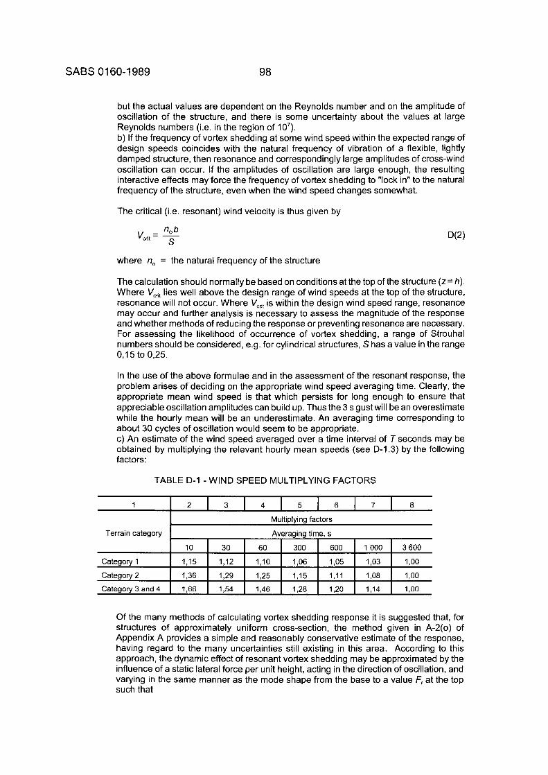
SABS 01 60-1 989 98
but the actual values are dependent on the Reynolds number and on the amplitude of oscillation of the structure, and there is some uncertainty about the values at large Reynolds numbers (i.e. in the region of 10'). b) If the frequency of vortex shedding at some wind speed within the expected range of design speeds coincides with the natural frequency of vibration of a flexible, lightly damped structure, then resonance and correspondingly large amplitudes of cross-wind oscillation can occur. If the amplitudes of oscillation are large enough, the resulting interactive effects may force the frequency of vortex shedding to "lock in" to the natural frequency of the structure, even when the wind speed changes somewhat.
The critical (i.e. resonant) wind velocity is thus given by
where no = the natural frequency of the structure
The calculation should normally be based on conditions at the top of the structure ( z= h). Where V,, lies well above the design range of wind speeds at the top of the structure, resonance will not occur. Where Vcrit is within the design wind speed range, resonance may occur and further analysis is necessary to assess the magnitude of the response and whether methods of reducing the response or preventing resonance are necessary. For assessing the likelihood of occurrence of vortex shedding, a range of Strouhal numbers should be considered, e.g. for cylindrical structures, S has a value in the range 0,15 to 0,25.
In the use of the above formulae and in the assessment of the resonant response, the problem arises of deciding on the appropriate wind speed averaging time. Clearly, the appropriate mean wind speed is that which persists for long enough to ensure that appreciable oscillation amplitudes can build up. Thus the 3 s gustwill be an overestimate while the hourly mean will be an underestimate. An averaging time corresponding to about 30 cycles of oscillation would seem to be appropriate. c) An estimate of the wind speed averaged over a time interval of T seconds may be obtained by multiplying the relevant hourly mean speeds (see D-I .3) by the following factors:
TABLE D-I -WIND SPEED MULTIPLYING FACTORS
Terrain category
Of the many methods of calculating vortex shedding response it is suggested that, for structures of approximately uniform cross-section, the method given in A-2(0) of Appendix A provides a simple and reasonably conservative estimate of the response, having regard to the many uncertainties still existing in this area. According to this approach, the dynamic effect of resonant vortex shedding may be approximated by the influence of a static lateral force per unit height, acting in the direction of oscillation, and varying in the same manner as the mode shape from the base to a value F, at the top such that
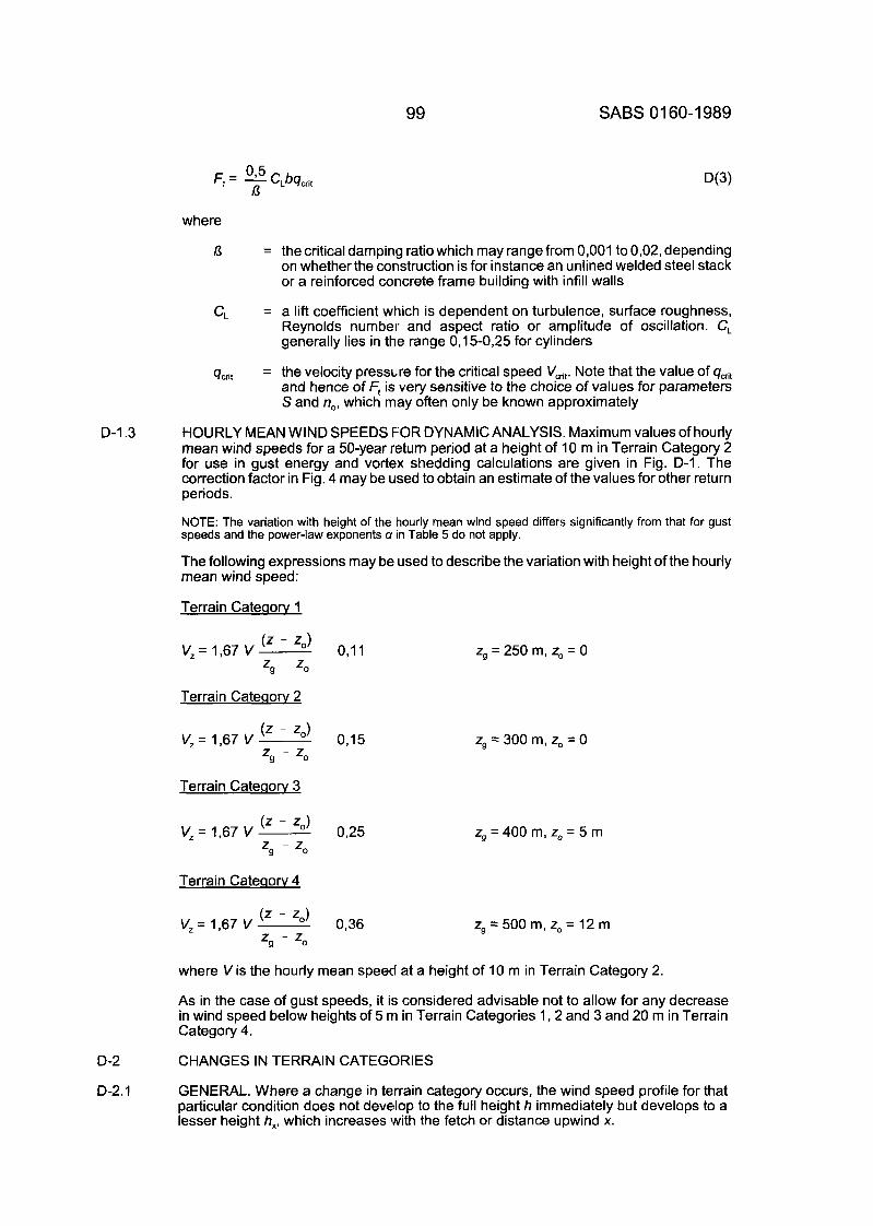
99
0 5 n F, = I C,bq,,
SABS 01 60-1 989
where
13 = the critical damping ratio which may range from 0,001 to 0,02, depending on whether the construction is for instance an unlined welded steel stack or a reinforced concrete frame building with infill walls
= a lift coefficient which is dependent on turbulence, surface roughness, Reynolds number and aspect ratio or amplitude of oscillation. C, generally lies in the range 0,15-0,25 for cylinders
= the velocity pressure for the critical speed Vcrit. Note that the value of qcht and hence of Fp is very sensitive to the choice of values for parameters S and no, which may often only be known approximately
HOURLY MEAN WIND SPEEDS FOR DYNAMIC ANALYSIS. Maximum values of hourly mean wind speeds for a 50-year return period at a height of 10 m in Terrain Category 2 for use in gust energy and vortex shedding calculations are given in Fig. D-I. The correction factor in Fig. 4 may be used to obtain an estimate of the values for other return periods.
NOTE: The variation with height of the hourly mean wind speed differs significantly from that for gust speeds and the power-law exponents U in Table 5 do not apply.
The following expressions may be used to describe the variation with height of the hourly mean wind speed:
Terrain Cateaorv 1
CL
qcdt
D-I .3
D-2
D-2.1
(z - Z O ) o,ll V, = 1,67 V zg - zo
Terrain Cateaorv 2
(z - zo) o,15 V, = 1,67 V zg - zo
Terrain Cateclorv 3
Terrain Cateaorv 4
zg = 250 m, z, = 0
zg = 300 m, zo = 0
zg = 400 m, zo = 5 m
zg = 500 m, z, = 12 m
where V is the hourly mean speed at a height of 10 m in Terrain Category 2.
As in the case of gust speeds, it is considered advisable not to allow for any decrease in wind speed below heights of 5 m in Terrain Categories 1, 2 and 3 and 20 m in Terrain Category 4.
CHANGES IN TERRAIN CATEGORIES
GENERAL. Where a change in terrain category occurs, the wind speed profile for that particular condition does not develop to the full height h immediately but develops to a lesser height h,, which increases with the fetch or distance upwind x.
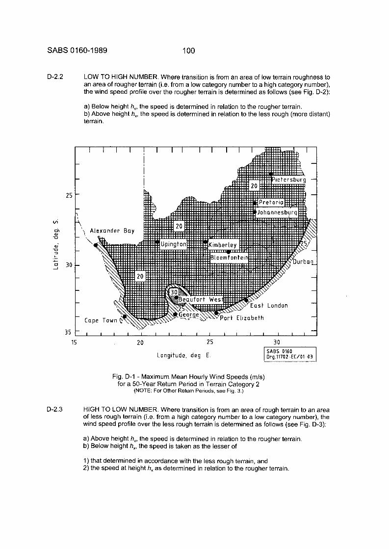
SABS 01 60-1 989 100
D-2.2
25
wi rir (U U
al U 7
c
1
c 30
35
LOW TO HIGH NUMBER. Where transition is from an area of low terrain roughness to an area of rougher terrain (i.e. from a low category number to a high category number), the wind speed profile over the rougher terrain is determined as follows (see Fig. D-2):
a) Below height h,, the speed is determined in relation to the rougher terrain. b) Above height h,, the speed is determined in relation to the less rough (more distant) terrain.
15 20 25 30
Longi tude, deg. E
Fig. D-I - Maximum Mean Hourly Wind Speeds (m/s) for a 50-Year Return Period in Terrain Category 2
(NOTE: For Other Return Periods, see Fig. 3.)
D-2.3 HIGH TO LOW NUMBER. Where transition is from an area of rough terrain to an area of less rough terrain (i.e. from a high category number to a low category number), the wind speed profile over the less rough terrain is determined as follows (see Fig. D-3):
a) Above height h,, the speed is determined in relation to the rougher terrain. b) Below height h,, the speed is taken as the lesser of
1) that determined in accordance with the less rough terrain, and 2) the speed at height h, as determined in relation to the rougher terrain.
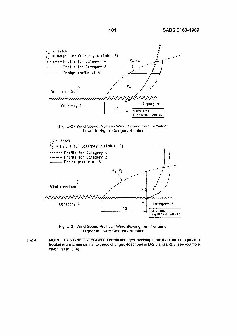
101 SABS 0 1 60-1 989
D-2.4
0 0
x q = fetch
0 . 0 0 0 Profile for Category 4 ---- Profile for Category 2
0
0 0 h, height for Category 4 (TabLe 5)
Design profile a t A
‘ ’ /’
/ /
4 Wind direction
Category 2
Drg.1143O-EC/00-07
Fig. D-2 - Wind Speed Profiles - Wind Blowing from Terrain of Lower to Higher Category Number
x 2 = fetch hg height for Category 2 (Table
* * * * * * Profile for Category 4 _ _ _ _ Profile for Category 2 - Design profile a t A
I I I 1
51
I---
,/- h2 ex2
/ **
/ 0 JO--’ : / / /
/
---+ Wind direction
Category 4
Fig. D-3 -Wind Speed Profiles - Wind Blowing from Terrain of Higher to Lower Category Number
MORE THAN ONE CATEGORY. Terrain changes involving more than one category are treated in a manner similar to those changes described in D-2.2 and D-2.3 (see example given in Fig. D-4).
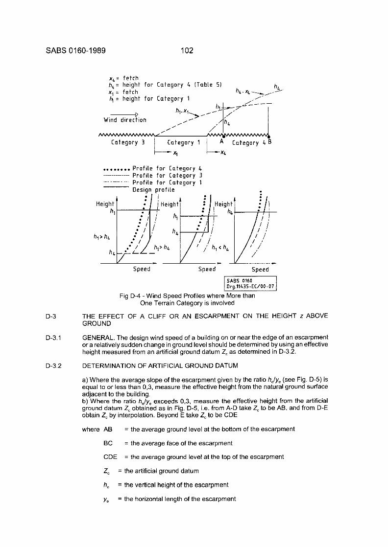
SABS 01 60-1 989 102
x b = f e t c h h,= height for C a t e g o r y 4 ( T a b l e 5)
-----D h x 1. lb//21g7- /
C a t e g o r y 3
h 5 x , = f e t c h 4 = h e i g h t for C a t e g o r y 1
h,. x, >,- ,I
/----
0 /
Wind d i rec t i on
/' 0 /
0
........ P r o f i l e f o r Ca tegory 4 P r o f i l e f o r C a t e g o r y 3 P r o f i l e for C a t e g o r y 1 Design p r o f i l e
._-_____-___-
Speed Speed Speed
I SABS 0160 Dra.11435-EC/00-07
1 - I
Fig D-4 -Wind Speed Profiles where More than One Terrain Category is involved
D-3 THE EFFECT OF A CLIFF OR AN ESCARPMENT ON THE HEIGHT z ABOVE GROUND
D-3.1 GENERAL. The design wind speed of a building on or near the edge of an escarpment or a relatively sudden change in ground level should be determined by using an effective height measured from an artificial ground datum Z, as determined in 0-3.2.
DETERMINATION OF ARTIFICIAL GROUND DATUM D-3.2
a) Where the average slope of the escarpment given by the ratio helye (see Fig. D-5) is equal to or less than 0,3, measure the effective height from the natural ground surface adjacent to the building. b) Where the ratio helye exceeds 0,3, measure the effective height from the artificial ground datum Z, obtained as in Fig. D-5, i.e. from A-D take Z, to be AB, and from D-E obtain Z, by interpolation. Beyond E take Z, to be CDE
where AB = the average ground level at the bottom of the escarpment
BC
CDE
= the average face of the escarpment
= the average ground level at the top of the escarpment
Z, = the artificial ground datum
he
ye
= the vertical height of the escarpment
= the horizontal length of the escarpment
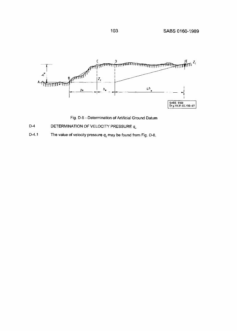
103 SABS 01 60-1 989
I
Fig. D-5 - Determination of Artificial Ground Datum
D-4
D-4.1
DETERMINATION OF VELOCITY PRESSURE q,
The value of velocity pressure q, may be found from Fig. D-6.
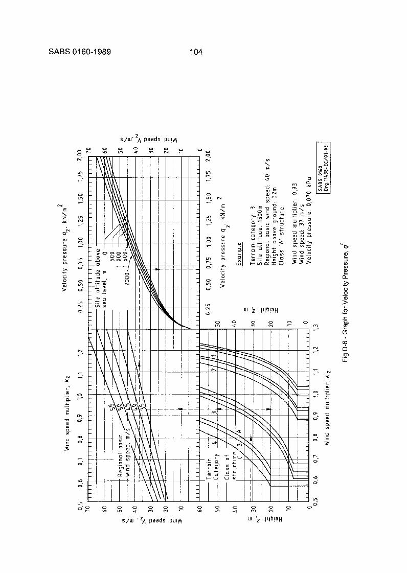
SABS 01 60-1 989 104
N E \ z Y
N U
(U
3 VI VI (U
a
% + U 0 (U
L
L
- - >
N Y
L aJ ._ - a .- L - 2 U (U aJ IA
U
n
G 3
2 s / w ' A p a a d s PUIM
I 0 0 0 N
0 m
0 N
0 7
o - ~ O O O O O O - v r f r n ~ -
S/UI ' 'A p a a d s PUIM
0 0 0 N
m
O N-
0 0 0 a o o - I m c t r n " T - M
U c ._ 3
105 SABS 01 60-1 989
E-I
E-2
E-2.1
E-2.2
E-3
E-3.1
APPENDIX E. DEFORMATION OF BUILDINGS (This appendix does not form part of the provisions of the code)
NOTE
a) The information contained in this appendix is based on information given in IS0 4356. b) The following definitions relate only to words or phrases appearing in this appendix:
Lonq-term temporary action. Any action that occurs either for relatively long periods of time or for short periods of time that recur repeatedly over a long period. Short-term temporary action. Any actiori that occurs only for short periods of time and that affects the structure infrequently. Temporaw action. Any action that occurs only at certain times during the construction or existence of the structure, or whose magnitude cannot in practice be considered constant.
GENERAL
The aim of this appendix is to assist the designer to identify those aspects of deformation that affect the suitability of a building for the purposes for which it is intended, and to suggest criteria by which the performance of the building can be assessed. In addition, numerical values for some of these criteria are suggested in order to give some guidance where this might be desired.
The recommendations for criteria of deformation, and the suggestions for limiting values, are given in Table 1 and in Tables E-I to E-5 of this appendix.
In view of the wide range of acceptable values of some of the criteria, and in view also of the difficulties of estimating deformations, it is believed that some guidance towards uniformity and degree of compliance would be of assistance, particularly as the economics of modern building designs are increasingly controlled by deformation and maintenance during use.
Some suggestions are therefore made in regard to the methods for controlling the assessment of deformations.
AP PL CATION
TYPE OF BUILDING. This appendix refers to the deformations at the serviceability limit states of buildings that are covered by this code of practice, namely
a) residential and institutional buildings; b) offices and commercial buildings; c) public buildings; and d) storage and general industrial buildings.
ADJACENT BUILDINGS. Attention is drawn to the fact that the provision of movement joints between adjacent buildings and the avoidance of interference with neighbouring foundations are normal good building practice, and that it is undesirable that the deformations of a building damage adjacent buildings or inconvenience their occupants or other members of the public.
CAUSES OF DEFORMATION
GENERAL. Deformations are caused by major ground movements, by differential settlements of foundations, by environmental and occupational loads, by pre-stressing forces and by movements of building materials owing to creep and changes in temperature, in moisture content iand in chemical composition.
SABS 01 60-1 989 106
E-3.2 EFFECTS AND REMEDIES. Beside possibly affecting the strength or stability of a structure, deformations may affect serviceability by causing damage to adjacent parts of the building, by disturbing or harming the occupants, or by preventing proper use of the building.
In many such cases, the designer may be able to avoid troublesome effects either by removing the original cause or by taking suitable precautions in the process of design and construction to permit some or all of the deformation to occur freely, before or after completion of the building, and masking the remainder by suitable constructional or decorative treatment. This course of action has the advantage that it avoids the problem of precisely estimating the magnitudes of causes and their effects. It can be adopted when the deformations, and the constructional measures taken, do not conflict with other requirements of the design. Some troubles that may often be dealt with in this way are listed in E-8.
Camber can be used to reduce the final value of deflections. The normal use of camber is to reduce the contribution to deformations that is made by self-weight and other permanent or long-term temporary action. In other cases, the designer may have no option but to provide sufficient stiffness to limit the deformations and thus reduce their effects to acceptable levels; this will inevitably increase the first cost of the structure. The designer may choose this course or choose to combine both approaches.
E -4 L I M lTATl0 N S
E-4.1 GENERAL. Limitations may need to be applied to vertical or horizontal deflections or deviations, to inclinations, to curvatures, to the widths of cracks or to the effects of vibrations.
The limitation of beam or slab deformations may be basically a matter of deflection, rotation or curvature. However, these requirements are specified throughout this document in terms of deflection, or of deflection in relation to span, since this is the most easily observable parameter. For simply supported spans under uniformly distributed loading, the slope at the ends may be taken as equal to 3 times the ratio of medial deflection to span, and the radius of curvature at the middle as equal to the span divided by 10 times the deflection/span ratio.
E-4.2 LEVELS OF MAGNITUDE. When specifying limitations, it is necessary to consider the levels of magnitude at which the actions that cause deformations should be assumed to occur. A knowledge of this is essential if designers and the local authorities are to find a common basis for assessing and controlling deformations.
Some of the factors that enter into this consideration are
a) the extent to which information is available about the actions or properties involved, and the degree of accuracy of any estimates of the effects likely to be produced; b) the possible response of the building or member, in view of the duration of the action in question; c) the probability of the simultaneous occurrence of several actions contributing to a given kind of deformation; d) the consequent levels of dissatisfaction.
In connection with (c) above it will be noted that both spatial and chronological variations of disturbing actions are involved and also that, given the necessary data, an estimate of the combined probability might be made; in the absence of sufficient data it becomes necessary to adopt other means of expressing the reduced magnitudes of several actions that should be assumed to be present simultaneously.
107 SABS 01 60-1 989
E-5
E-5.1
E-5.2
E-5.3
In connection with (d) above it will be noted that the sharp limit to acceptability that is exceeded at the ultimate limit state does not, in general, exist together with serviceability limit states and there is usually a wide range of acceptable levels of deformation, depending on the properties of coritiguous materials, the reactions of individual persons, and the possibilities and economics of repair. In this connection, it is to be noted that in the case of widespread natural actions such as wind, snow and earthquake, whose characteristic values are based on time-related rather than space-related probabilities, the acceptable level of troubles due to deformation depends on the number of buildings simultaneously at risk and on the acceptability of some of the results of a natural calamity.
It is suggested that the limitations be based on the following:
1) The actions to be taken into account when deformations are specified or checked should be those having a duration that is appropriate to the response of the building or member affected; 2) for permanent actions, for long-term temporary actions and for short-term temporary actions affecting many buildings in the course of a single year, the design levels of magnitude of these actions should be the characteristic values; 3) a lower value than the characteristic may be specified when two or more of the above actions occur simultaneously, or when a short-term action is not likely to affect many buildings in the course of a single year.
STRENGTH AND STABILITY
GENERAL. Deformations affecting the strength and stability of a building or of its parts are taken into account in the process of structural design for the ultimate limit state. It is, however, necessary that designers be aware of certain cases involving static or dynamic instability where the conditions existing during normal use of the building may have a considerable effect on the ultimate limit state.
ECCENTRIC LOADING OF WALLS AND COLUMNS
a) Eccentric loading of walls and columns may occur as a result of excessive constructional deviation through inclination of these members or through deflections of floors or roof members. In both cases, the effects may be progressive and lead to collapse. b) Inclination of vertical members may be due to constructional deviations or to the effects of wind load, or of permanent and imposed loads or snow loads acting eccentrically or causing differential settlement. The presence of properly designed stiffening elements such as shear walls, central service cores, enclosed liftwells or staircases may improve stability. c) Any change of slope of floors alr roofs at junctions with supporting walls or columns, that takes place after construction, may produce loading of the latterthat is both eccentric and inclined. Such changes of dope may be due to the effects of permanent and imposed and snow loads on the floors or roof members, the permanent load causing creep deflection and the imposed and snow loads causing elasticdeflection and possibly creep deflection. It is difficult for the designer to assess the problem if he is not aware of the probable deformation of the floor or roof member, as may be the case if the member is not designed by him.
RESONANCE. Near-coincidence of forced and natural vibrations may produce resonance of any building element. The degree of resonance may be reduced by appropriate adjustment of either of the two frequencies, or by the provision of vibration insulation or adequate damping. The problem arises mainly where the disturbing force is of large magnitude, i.e. in auditoria, in dance halls and in grandstands, and in buildings having long span suspended floors with a natural frequency of about 1-5 Hz, or containing machines with large unbalanced forces.
SABS 01 60-1 989 108
E-6
E-6.1
E-6.2
E-6.2.1
E-6.2.2
E-6.2.3
SERVICEABILITY
GENERAL. Deformations, although possibly not affecting the strength or stability of a building, may cause damage to members (load-bearing or otherwise) and to finishes and claddings.
They may produce unpleasant psychological effects, even to the extent of causing alarm. Finally, they may be physically such as to effectively prevent the use of the building for its intended purpose or to impair the health of the occupants. Some deformations may produce more than one kind of effect.
DEFORMATIONS CAUSING DAMAGE TO THE BUILDING
Crackina and SDallina of Walls. Change of slope of floors and roofs at junctions with supporting walls or columns and lifting of the insufficiently restrained corners of torsionally stiff floor slabs may cause horizontal cracking (particularly undesirable where floors are carried through to the face of the external wall) and also spalling of internal or external finishes. The actions involved are permanent load causing creep deflection and the imposed floor load and any roof load (including snow) causing elastic deflection and creep deflection.
Differential settlement and wind forces may also cause such cracking and spalling. Thermal and moisture movements in finishes are also involved. More severe limitation may be necessary if deep edge stiffening beams are incorporated into the walls.
Crackina and SDallina of Ceilinas. Curvature of the floor or roof may cause cracking in decoration on the underside of concrete slabs. Curvature subsequent to plastering may cause cracking of the plaster in the span and spalling in regions of negative curvature. The actions involved are the permanent loading of the floors or roofs causing creep deflection and the imposed loading causing elastic deflection and possibly creep deflection. Repeated thermal and moisture movements in the plaster may also be involved. Good extensibilityof the plaster and good distribution of concentrated loads are ameliorating factors as is also the fact that cracks may be covered by redecoration. The permissible degree of cracking is largely subjective but depends on the use of the building.
Crackina and Spallina of Brittle Partitions and Non-loadbearinq Walls
a) Apart from cracking, spalling and local bulging due to thermal and moisture movements in the partitions themselves, or in the supporting structure, damage to brittle partitions may arise as a result of the differential settlement of foundations, deflection of floors or roofs, or lateral movements of the building.
Estimation of this damage depends on a determination of the total tensile or compressive effects arising from all causes, together with information about the limiting tensile and compressive properties of the partitions, the effects on the number and width of cracks of any restraints to movement, and the degree of cracking that can be tolerated for the given type of surface finish and the given use of the building. Such procedure is not yet sufficiently developed and it is meanwhile recommended that the deformation arising from various causes be dealt with separately. The suggested limiting values may permit a certain amount of cracking. Where this cannot be accepted, a more severe limitation, or more tolerant partitions, may be called for. b) Differential settlement of foundations subsequent to the erection of partitions may produce diagonal cracking across the body of the latter. The actions involved are the self-weight load, including that of the partitions, and all long-term temporary actions capable of influencing settlement.
109 SABS 01 60-1 989
c) Deflections of floors or roofs may damage partitions in a number of ways. In all cases the effects involved are those occurring after the erection of partitions, i.e. the self-weight load of the floor or roof, and in some cases that of the partitions, together with any pre-stress, causes creep deflections; the imposed floor or roof load (including snow load and any self-weight loads such as screeds and floor finishes applied after erection of partitions) causes elastic deflection and creep deflection; also, curvature and other movements of the floor may be caused by possible unrestrained moisture movements. In general, the greater the rigidity of the floor transverse to the span, the worse are the effects of its deformations. Three main types of behaviour are known:
1) With the first type of behaviour, i3 partition parallel to the span deforms in its own plane to follow the deformations of the floor below it, possibly producing vertical cracks in the bending tension zone, diagonal shear cracks, or a gap above the partition. This type of behaviour is most likely to occur where the partition is of relatively long span (length/height exceeding 3,5 approximately for non-cantilevered spans); or is not longitudinally restrained by the structure or by contiguous partitions; or contains many openings; or is of low rigidity. In this case, apart from the weight of the partition concerned, one of the actions involved is the contribution from the weight of partitions on the floor or floors above, assuming that this can be transmitted to the partition in question.
In the case of a cantilevered span, there is a greater possibility of cracking in the upper part of the partition and damage to fascias owing to non-uniform deflection of supporting cantilevers. 2) With the second type of behaviour, a partition parallel (or in some cases transverse) to the span tends to support itself by arching horizontally or diagonally. This is most likely to occur where the partition has a high compressive modulus and limit of deformability; where the ratio of length to height lies in the range 1,535 approximately; where the partition is longitudinally restrained by the structure or by contiguous walls or partitions; and where there are few openings or continuous vertical sliding joints to interfere with the arching.
If, in such case, the floor below the partition deflects more than the partition (possibly owing to the absence of a partition, a stiffening beam, or other support underneath), a horizontal crack may be formed along the base of the partition, or a horizontal or arc-shaped crack may be formed in the lower portion of the partition, together with diagonal cracks across the upper corners owing to extension of the undersurface of the floor above. (If such horizontal cracks are likely to occur, their formation may be limited to the floor level where they can Subsequently be masked by the provision of a chase or a separation layer. The cracks can then be masked by a skirting board fixed to the floor.)
If, on the other hand, the floor or roof above the partition deflects more than does the partition and there is no compressible packing at the head of the partition, the partition tends to be crushed and there may be vertical cracks in the lower part and diagonal cracks across the upper corners. 3) With the third type of behaviour, the partition is loaded by the upper floor and carries these loads by strut-action to the ends of the span of the lower floor. This is most likely to happen when the ratio of length to height of the partition is less than 1 3 approximately. The type of damage is the same as in (2) above.
When the partitions have openings, a combination of some of the above phenomena is likely to occur or there may be simple rotation of the parts of the partition. Diagonal cracks radiating from the corners of the openings may also be produced. Some horizontal or inclined reinforcement at such places is therefore advisable where it is not possible to break the continuity of the partition above or below the opening. d) Lateral deflection of a building as a result of wind forces may cause diagonal cracking across the body of a partition. The action involved is that of the wind gust in having a duration of sufficient length to produce the necessary deflection. Low-cycle fatigue damage may occur. Strong shear walls, central core zones or enclosed staircases have an ameliorating effect.
SABS 01 60-1 989 110
E-6.2.4
E-6.3
E-6.3.1
E-6.3.2
E-6.4
E-6.4.1
E-6.4.2
E-6.4.3
Damaae to Roof Coverinas. Claddinq and Glazinq. Deflections of roofs may cause damage to roof coverings of felt or metal, to roof sheeting or to roof glazing or tiling. The actions involved are the production of creep deflections by the permanent load and the production of elastic deflections by any imposed load, snow or hail loading, and/or wind gusts of appropriate duration.
The limitation of deflection may need to be more restrictive for roofs covered with sheet materials which become brittle with age. The cladding fixing should be so designed that structural loads are not transferred to cladding panels when the structural frame deforms.
DEFORMATIONS AFFECTING APPEARANCE
Visible Saa of Floors and Ceilinas. Visible deviations of floors and ceilings from the straight line or plane (unless obviously intentional) cause subjective feelings that are unpleasant and possiblyalarming. The actions involved are those of the permanent load and the imposed loads in producing elastic deflections and possibly creep deflections, and also constructional deviations and thermal and moisture movements and, in the case of cantilevers, differential settlement. The provision of a camber or of a false ceiling can improve matters.
Subjective appraisal depends on the type of roof or floor (whether flat soffit, beam and slab, trough or ribbed construction), the area of it that is visible, its height and its relationship to other elements of the construction (particularly elements that are horizontal or in a horizontal plane), and the lighting conditions.
Visible Lean of Walls and Columns. Visible deviation of vertical members from the vertical (unless obviously intentional) is also a source of subjective unrest. The actions involved are those of the dead (self-weight) loads and imposed loads causing differential settlements, but constructional deviations and the overturning effects of eccentric and inclined loads on walls and columns may be contributing factors. Persons vary in their appraisal of lean but are often guided by neighbouring vertical elements.
DEFORMATIONS AFFECTING USE
Curvature of Floors. Curvature of floors and the inclinations that it produces may cause people to stumble or slip, trolleys to move, furniture and equipment to tilt or rock, and spilt liquids to spread. Curvature may be due to constructional deviations and to elastic deflections and creep deflections (possibly upward) under permanent load alone or under permanent load and imposed floor loads, or to thermal or moisture movements. The provision of screeds or a camber may be appropriate.
Non-horizontalitv of Floor SURRO~~S. Unintentional lack of horizontality of floor supports causes a number of the effects referred to in E-6.4.1. It may be due to constructional deviations or to differential settlement under dead (self-weight) loads and imposed floor loads, or to rotation of the point of support in the case of cantilevers.
Oscillations Generated Within the Buildinq or bv Wind Forces. Apart from man-made external sources of vibration, such as nearby industrial and transport activities, whose effects are not a matter for this appendix, the main sources of oscillations of buildings are foot traffic and machinery within the building, together with wind gusts. (Earthquakes are dealt with in E-6.5.2.) The acceptable magnitudes of such oscillations, which may cause unpleasant sensations, including alarm, or prevent the carrying on of required activities, depend on human sensitivity, on the activity to be pursued, on the degree of damping present, and on the duration of the impulses and the interval between them. Recommendations for the limitation of oscillations of frequency exceeding 1 Hz are given in IS0 2631.
111 SABS 01 60-1 989
E-6.4.4 Deformations Affectina Special Reauirements in Use
E-6.4.4.1 General. E-6.4.1 to E-6.4.3 refer to deformations affecting the use of common types of buildings within the scope of this code of practice. However, in certain types of buildings there may be special requirements in connection with, for example, particular activities of occupants or the use of machinery or precision apparatus. Examples of such requirements are as follows:
a) Deflections of overhead travellins crane airders. Travelling cranes produce
1) vertical deflections of the runway girders (and of supporting brackets in some cases) owing to their self-weight and that of the load carried, and 2) horizontal lateral and longitudinal deflections of the supporting columns owing to the forces of acceleration and braking.
(It is assumed here that the effects of constructional deviations and any subsequent movements of supports have been negated by the levelling and lining up of the crane rails. Any upward deflection due to pre-stress may be taken into account.)
In the case of vertical deflection:; of the runway girders, there may be a problem of clearances. The principal problems, however, are the overloading of the means of propulsion owing to the slope of the runway girders when under load and the maintenance of steady motion over the points of support.
In the case of horizontal deflections of the columns, it is necessary to limit the transverse deflection to prevent the crane gantry itself from rotating excessively about the vertical (slewing), or becoming dislodged, and also to limit both transverse and longitudinal deflections to prevent excessive deformations of the supporting columns from leading to damage to cladding and fixings (or to instability; see E-6.2).
b) Other special requirements. These requirements should be agreed upon in consultation with the owner and the suppliers of any equipment involved, before design and construction commences. Examples of problems that may arise are
1) vibration of weighing and measuring apparatus; 2) damage to impermeable membranes used for isolation or protection of liquids and gases; 3) twist of floors carrying machines operating on sheet materials; 4) inclinations affecting co-linearity of apparatus or levels of liquids; 5) interference with fine manual movements.
E-6.5 DEFORMATIONS REQUIRING GENERAL OVERALL CONTROL
E-6.5.1 General. Cracks in building elernents may damage coverings, permit corrosion of reinforcing elements or allow penetration of liquids, gases or radiation (thus, for example, reducing thermal or airborne sound insulation, or admitting rain, dust or light). Cracks may also constitute disfigurement or cause alarm. (They are unlikely to cause structural collapse unless extremely wide and extensive, but they are early evidence of excessive action.)
In many cases, cracks may be avoided, may be located in one or more convenient places or may be hidden, by means of appropriate initial design and construction measures. In other cases, the requirements of standards for other types of deformation may prevent the formation of cracks.
However, it must be borne in mind that design and construction measures may be only partially successful in controlling cracking, and that, in any event, cracks may occur in circumstances other than those provided for in standards; it is necessary to impose a general overall limitation on the width of cracks.

SABS 01 60-1 989 112
In laying down limitations, consideration must be given to the building materials involved, whether the cracks are through-cracks or surface cracks, whether they are likely to open further or close, whether they are repairable or capable of being covered by decoration, whether penetration of liquids, etc., is a factor, and the probable attitude of persons affected, in view of the intended use of the building.
In the case of possible corrosion of reinforcement, the permissible width of cracks should be laid down in consultation with specialist organizations. Where corrosion of reinforcement is not in question,
1) through-cracks should not be permitted at positions where the transfer of water (e.g. by gravity, wind pressure or capillary actions) to the inside surfaces of rooms could occur; 2) cracks should individually not exceed an average width of 0,2 mm if it is intended that they be coverable by redecoration; 3) if cracks are likely to be permanent, neither through-cracks nor surface cracks should individually exceed an average width of 2 mm, or such lower figure as may be required in particular circumstances (for example, in the presence of corrosive or humid atmospheres).
The widths of cracks and any resulting out-of-plane dislocations may be controlled by prestressed (or other) reinforcement.
E-6.5.2 Deformations Due to Earthauakes. Apart from the hammering of adjacent buildings owing to insufficient clearance as referred to in E-8(d), oscillations during an earthquake may cause considerable damage. Methods of predicting and assessing the damage are still the subject of disagreement between experts, and research continues.
It is therefore not possible at present to make any recommendation regarding limitation of deformation during an earthquake.
E-7 METHODS OF ASSESSING PROBABLE DEFORMATIONS
The method used to assess or control the probable deformation is a matter for the structural designer. For example, he may determine deformations by calculation or by model or prototype testing; he may control them by the adoption of limiting span/depth ratios or other measures. Whatever the method used, it should be such that it gives an acceptable probability of meeting the requirements given in this appendix. A probability of not exceeding limits of 97 % is suggested as a desirable minimum.
When deformations are determined by calculation, such calculation should be based on the characteristic values of actions (loads, moisture movements, thermal movements) and of properties of members (elastic properties, creep and thermal coefficients of materials, and dimensions), due allowance being made (as provided for in E-4.2(c)) for any appropriate combinations of other parameters.
The calculations should take into account constructional deviations, thermal movements, moisture movements, cracking of reinforced materials, and creep of materials under permanent and long-term temporary loads. In addition, the assistance received from various sources (for example, partial fixity at ends of beams and slabs, partial support from partitions), that cannot be sufficiently relied upon when strength properties are assessed, may be taken into account.
In calculating any required camber, it is suggested that the magnitude of the action involved be the mean value.
The deformation limitation to be met should be the most severe of any values suggested for any particular criterion.
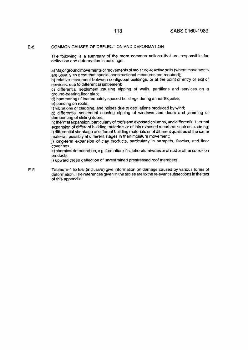
113 SABS 01 60-1 989
E-8
E-9
COMMON CAUSES OF DEFLECTION AND DEFORMATION
The following is a summary of the more common actions that are responsible for deflection and deformation in buildings:
a) Major ground movements or movements of moisture-reactive soils (where movements are usually so great that special constructional measures are required); b) relative movement between contiguous buildings, or at the point of entry or exit of services, due to differential settlement; c) differential settlement causing nipping of walls, partitions and services on a ground-bearing floor slab; d) hammering of inadequately spaced buildings during an earthquake; e) ponding on roofs; f) vibrations of cladding, and noises due to oscillations produced by wind; g) differential settlement causing nipping of windows and doors and jamming or demounting of sliding doors; h) thermal expansion, particularly of roofs and exposed columns, and differential thermal expansion of different building materials or of thin exposed members such as cladding; i) differential shrinkage of different building materials or of different qualities of the same material, possibly at different stages in their moisture movement; j) long-term expansion of clay products, particularly in parapets, fascias, and floor coverings; k) chemical deterioration, e.g. forrriation of sulpho-aluminates or of rust or other corrosion products; I) upward creep deflection of unrestrained prestressed roof members.
Tables E-I to E-5 (inclusive) give information on damage caused by various forms of deformation. The references giver1 in the tables are to the relevant subsections in the text of this appendix.
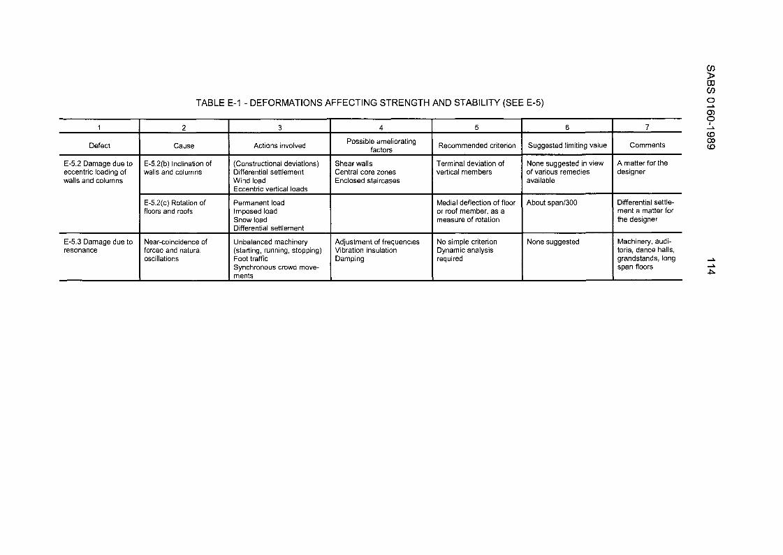
1
Defect
E-5.2 Damage due to eccentric loading of walls and columns
E-5.3 Damage due to resonance
TABLE E-1 - DEFORMATIONS AFFECTING STRENGTH AND STABILITY (SEE E-5)
7 I 3 I 4 I 5
Cause I Possible ameliorating Recommended criterion fartnrc I I Actions involved
E-5.2(b) Inclination of walls and columns
E-5.2(c) Rotation of floors and roofs
Near-coincidence of forced and natural oscillations
(Constructional deviations) Differential settlement Wind load Eccentric vertical loads
Permanent load Imposed load Snow load Differential settlement
Unbalanced machinery (starting, running, stopping) Foot traffic Synchronous crowd move- ments
Shear walls Central core zones Enclosed staircases
Adjustment of frequencies Vibration insulation Damping
Terminal deviation of vertical mem bers
Medial deflection of floor or roof member, as a measure of rotation
No simple criterion Dynamic analysis required
Suggested limiting value
None suggested in view of various remedies available
About span/300
7
Comments
A matter for the designer
Differential settle- ment a matter for the designer
None suggested Machinery, audi- toria, dance halls, grandstands, long span floors
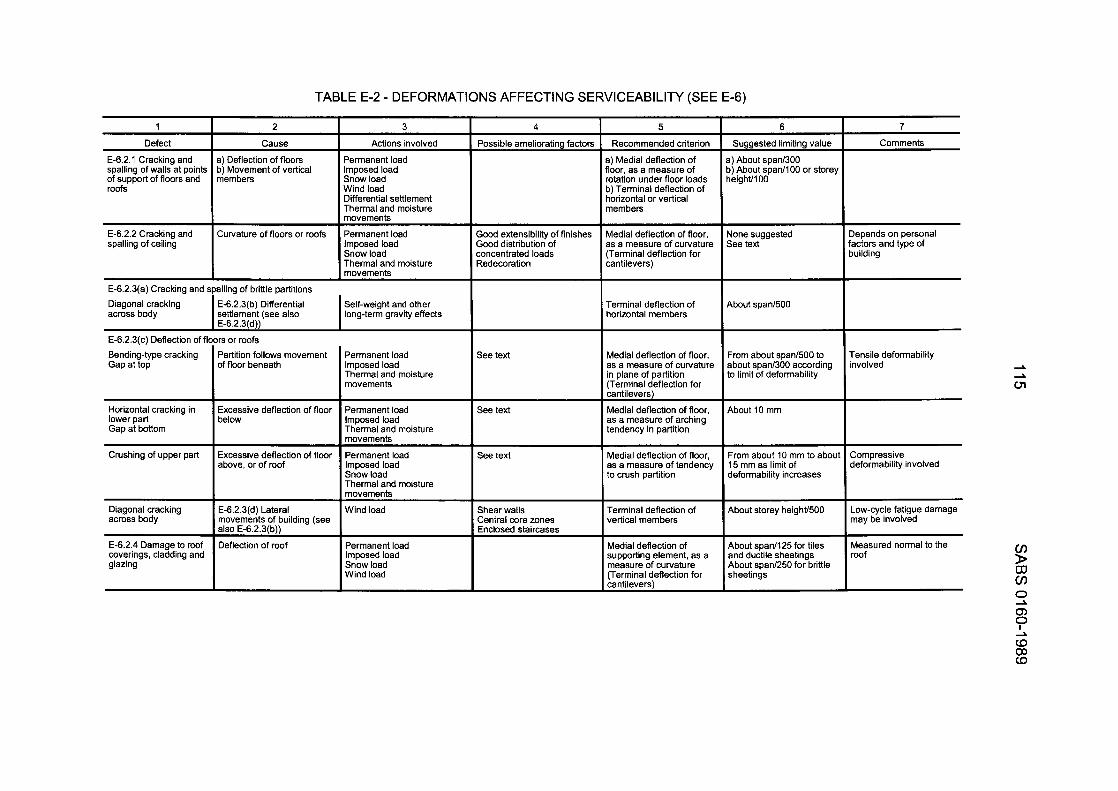
TABLE E-2 - DEFORMATIONS AFFECTING SERVICEABILITY (SEE E-6)
E-6.2.3(a) Cracking and
4 I 5
spalling of brittle partitions
1 2
Cause
a) Deflection of floors b) Movement of vertical members
Curvature of floors or roofs
3
Actions involved
Permanent load Imposed load Snow load Wind load Differential settlement Thermal and moisture movements
Permanent load Imposed load Snow load Thermal and moisture movements
See text
See text
as a measure of curvature in plane of partition (Terminal deflection for cantilevers)
Medial deflection of floor, as a measure of arching tendency in partition
Medial deflection of floor, as a measure of tendency to crush partition
6
Comments Defect
E-6.2.1 Cracking and spalling of walls at points of support of floors and roofs
Suggested limiting value
I ) About span/300 I) About span/100 or storey ieightllO0
Possible ameliorating factors Recommended criterion
a) Medial deflection of floor, as a measure of rotation under floor loads b) Terminal deflection of horizontal or vertical members
E-6.2.2 Cracking and spalling of ceiling
Sood extensibility of finishes Sood distribution of :oncentrated loads Redecoration
Medial deflection of floor, as a measure of curvature (Terminal deflection for cantilevers)
Vone suggested See text
Iepends on personal 'actors and type of luilding
Terminal deflection of horizontal members
Diagonal cracking across body
Self-weight and other long-term gravity effects I E-6.2.3(b) Differential
settlement (see also E-6.2.3fd)l
About span1500
E-6.2.3(c) Deflection of fli Bending-type cracking Gap at top
3rs or roofs Partition follows movement of floor beneath
Permanent load Imposed load Thermal and moisture movements
From about span1500 to about span/300 according to limit of deformability
Tensile deformability involved
Horizontal cracking in lower part Gap at bottom
About 10 mm Excessive deflection of floor below
Permanent load Imposed load Thermal and moisture movements
Permanent load Imposed load Snow load Thermal and moisture movements
Wind load
Crushing of upper part ~~
Excessive deflection of floor above, or of roof
Compressive deformability involved
From about 10 mm to about 15 mm as limit of deformability increases
Terminal deflection of vertical members
About storey heighV500 Diagonal cracking E-6.2.3(d) Lateral across body movements of building (see
coverings, cladding and glazing
Low-cycle fatigue damage may be involved
Measured normal to the roof
Shear walls Central core zones Enclosed staircases
Permanent load Imposed load Snow load Wind load
About span1125 for tiles and ductile sheetings About span1250 for brittle sheetings
Medial deflection of supporting element, as a measure of curvature (Terminal deflection for cantilevers)
Q)
?
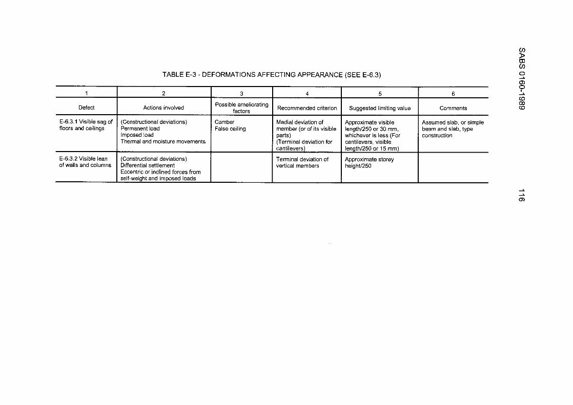
cn D m cn
2
Actions involved
1 3 4 5
Possible ameliorating factors Recommended criterion Suggested limiting value Defect
E-6.3.1 Visible sag of floors and ceilings
E-6.3.2 Visible lean of walls and columns
TABLE E-3 - DEFORMATIONS AFFECTING APPEARANCE (SEE E-6.3)
(Constructional deviations) Permanent load Imposed load Thermal and moisture movements
(Constructional deviations) Differential settlement Eccentric or inclined forces from self-weight and imposed loads
Camber False ceiling
Medial deviation of member (or of its visible
(Terminal deviation for cantilevers)
Terminal deviation of vertical members
Parts)
Approximate visible length/250 or 30 mm, whichever is less (For cantilevers, visible length/250 or 15 mm)
Approximate storey heighU250
0 3 m
I 6 2
to CO
Comments a
Assumed slab, or simple beam and slab, type construction
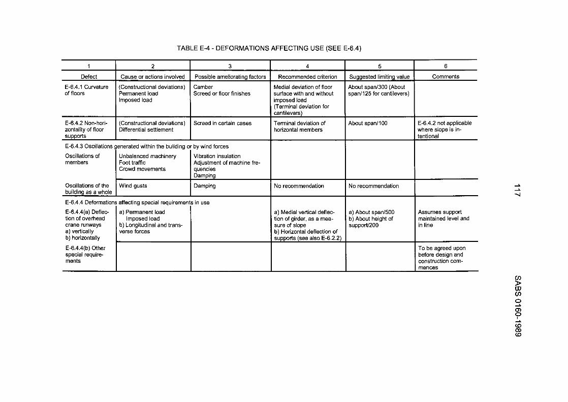
TABLE E-4 - DEFORMATIONS AFFECTING USE (SEE E-6.4)
(Constructional deviations) Differential settlement
1
Screed in certain cases
2 I 3
I
4 6
Comments Possible amelioratina factors Recommended criterion Defect
E-6.4.1 Curvature of floors
Cause or actions involved
(Constructional deviations) Permanent load Imposed load
Suggested limiting value
About span/300 (About span/125 for cantilevers)
Camber Screed or floor finishes
Medial deviation of floor surface with and without imposed load (Terminal deviation for cantilevers)
Terminal deviation of horizontal members
I I
About span/lOO E-6.4.2 Non-hori- zontality of floor supports
E-6.4.2 not applicable where slope is in- tentional I
E-6.4.3 Oscillations generated within the building or by wind forces I
Oscillations of members
Unbalanced machinery Foot traffic Crowd movements
Vibration insulation Adjustment of machine fre- quencies DamDina
No recommendation No recommendation Wind gusts I Damping Oscillations of the building as a whole
E-6.4.4 Deformation
E-6.4.4(a) Deflec- tion of overhead crane runways a) vertically b) horizontallv
affecting special requirement? in use
a) Permanent load Imposed load
b) Longitudinal and trans- verse forces
a) About span1500 b) About height of support1200
Assumes support maintained level and in line
a) Medial vertical deflec- tion of girder, as a mea- sure of slope b) Horizontal deflection of supports (see also E-6.2.2)
E-6.4.4(b) Other special require- ments
To be agreed upon before design and construction com- mences
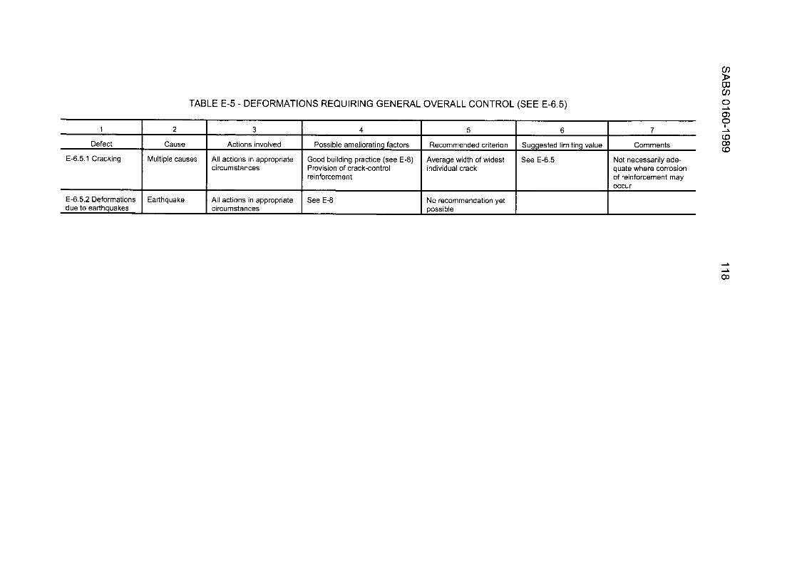
1
Defect
3
Actions involved
All actions in appropriate circumstances
E-6.5.1 Cracking
4 5 6
Possible ameliorating factors Recommended criterion Suggested limiting value
Good building practice (see E-8) Provision of crack-control individual crack reinforcement
Average width of widest See E-6.5
E-6.5.2 Deformations due to earthquakes
All actions in appropriate circumstances
TABLE E-5 - DEFORMATIONS REQUIRING GENERAL OVERALL CONTROL (SEE E-6.5)
occur
See E-8 No recommendation yet possible
L
Cause
Multiple causes
Earthquake
7
Comments
Not necessarily ade- quate where corrosion of reinforcement may
119 SABS 0160-1989
APPENDIX F. RAINFALL INTENSITY (This appendix does not form part of the provisions of the code)
F-I
F-2
F-3
GENERAL
While the code of practice covers loads and loadings that, in relation to rainfall, relate to horizontal areas and associated tributary areas, it is considered desirable to include in this appendix a brief guide to rainfall intensity as related to horizontal surfaces and to rainwater disposal from roofs.
Large variations in rainfall are encountered throughout the Republic of South Africa (see Fig. F-I), storms of high intensity and short duration being encountered in a number of localities. The increase in recent years in the number of reports of water damage to the contents of buildings has been, in the majority of cases, the direct result of an inadequate capacity of the drainage facilities for these high intensity, short duration storms. Such a lack of capacity can be due either to an underestimation in the design criteria or to lack of maintenance and repair on the part of the owner.
On sloping roofs, the overflow from eaves gutters that falls free of the building will not affect the building or its contents. On the other hand, with valley gutters and box gutters, any overflow can result in serious damage to the contents of the building and involve the owner in heavy compensation, repair and redecoration costs. In the case of flat roofs, ponding is responsible for water penetration into the building where waterproofing membranes or flashings (or both) are either ruptured or inadequate.
The concept of peak flow reduction of stormwater by "storage ponding" (or detention) is employed by a number of overseas countries to reduce the high initial flows experienced during high intensity, short duration rainstorms. If such an approach is considered within the Republic of South Africa for flat roofs (in the context of this code of practice), it will be necessary to give special attention to the waterproofing and design of such roofs.
DESIGN APPROACH
The general approach to the design of rainwater discharge has been to use charts prepared (generally) by the manufacturers of the various materials used. These charts are related to roof area when the size of gutters and discharge pipes is determined. The data are based usually on a rainfall intensity which is not necessarily related to the actual rainfall intensity of the area under consideration. A value of about 200 mm/h is sometimes used by some authorities.
The application of a general design value relieves the designer of the responsibility of establishing the design intensity criteria. The authority concerned has either established that such a value is adequate for design purposes, or is possibly prepared to admit responsibility for any excess volurne.
It is necessary for the designer to select a design intensity that is realistic for the area under consideration. This is particularly necessarywhen stormwater drainage is designed for buildings that house machinery, stock or materials whose replacement cost is high.
RA1 N FALL INTENSITY
F-3.1 ROOF FLOODING. Where a flat roof is provided with rainwater outlets built into the construction of the roof, it is essential that these outlets always be kept free of obstructions. This is particularly necessary for any roof where the construction is subject to increasing deflection with increasing load or where such a roof is surrounded by parapet walls or other upstands.
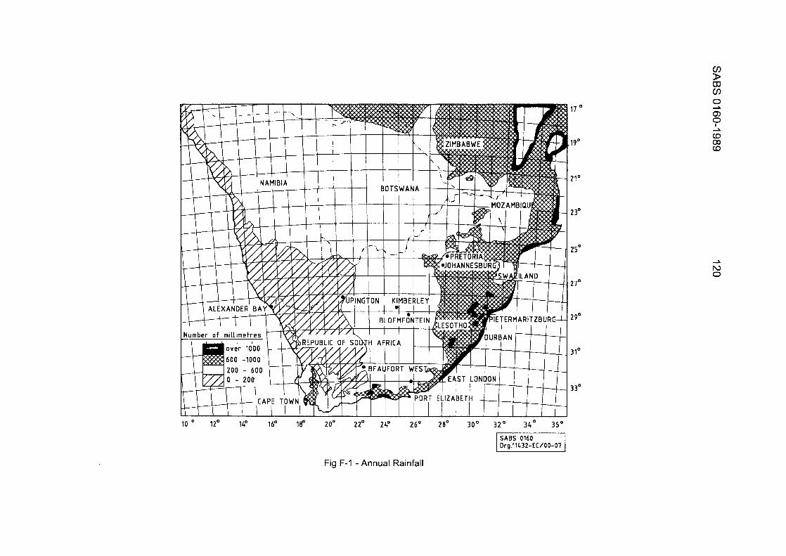
N 0
10 ' 12' 14' 16' 180 20' 22' 24" 26' 28' 30° 3 2 O 34' 36O
Fig F-I -Annual Rainfall
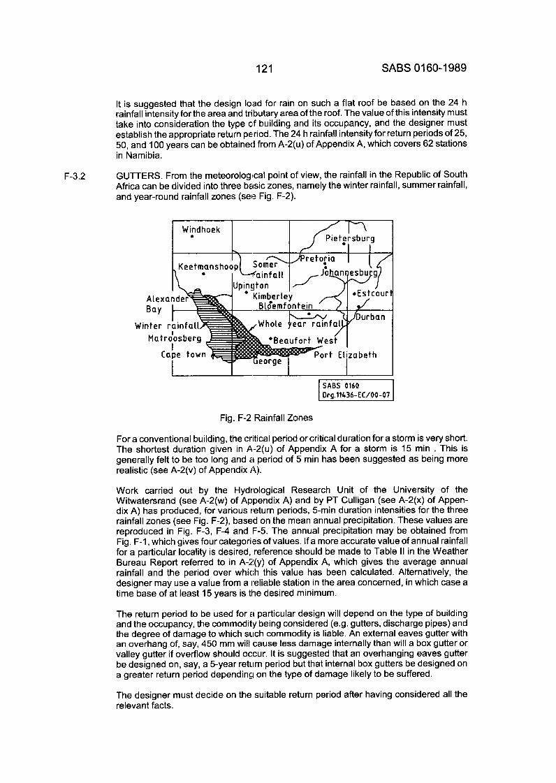
121 SABS 01 60-1 989
F-3.2
It is suggested that the design load for rain on such a flat roof be based on the 24 h rainfall intensity for the area and tributary area of the roof. The value of this intensity must take into consideration the type of building and its occupancy, and the designer must establish the appropriate return period. The 24 h rainfall intensity for return periods of 25, 50, and 100 years can be obtained from A-2(u) of Appendix A, which covers 62 stations in Namibia.
GUTTERS. From the meteorological point of view, the rainfall in the Republic of South Africa can be divided into three basic zones, namely the winter rainfall, summer rainfall, and year-round rainfall zones (see Fig. F-2).
I Windhoek I 3 I 0 I I Piet!rsburg
I I
I I I
Fig. F-2 Rainfall Zones
For a conventional building, the critical period or critical duration for a storm is very short. The shortest duration given in A-2(u) of Appendix A for a storm is 15 min . This is generally felt to be too long and a period of 5 min has been suggested as being more realistic (see A-2(v) of Appendix A).
Work carried out by the Hydrological Research Unit of the University of the Witwatersrand (see A-2(w) of Appendix A) and by PT Culligan (see A-2(x) of Appen- dix A) has produced, for various return periods, 5-min duration intensities for the three rainfall zones (see Fig. F-2), based on the mean annual precipitation. These values are reproduced in Fig. F-3, F-4 and F-5. The annual precipitation may be obtained from Fig. F-I , which gives four categories of values. If a more accurate value of annual rainfall for a particular locality is desired, reference should be made to Table II in the Weather Bureau Report referred to in A-2(y) of Appendix A, which gives the average annual rainfall and the period over which this value has been calculated. Alternatively, the designer may use a value from a reliable station in the area concerned, in which case a time base of at least 15 years is the desired minimum.
The return period to be used for 21 particular design will depend on the type of building and the occupancy, the commodity being considered (e.g. gutters, discharge pipes) and the degree of damage to which such commodity is liable. An external eaves gutter with an overhang of, say, 450 mm will cause less damage internally than will a box gutter or valley gutter if overflow should occur. It is suggested that an overhanging eaves gutter be designed on, say, a 5-year return period but that internal box gutters be designed on a greater return period depending on the type of damage likely to be suffered.
The designer must decide on the suitable return period after having considered all the relevant facts.
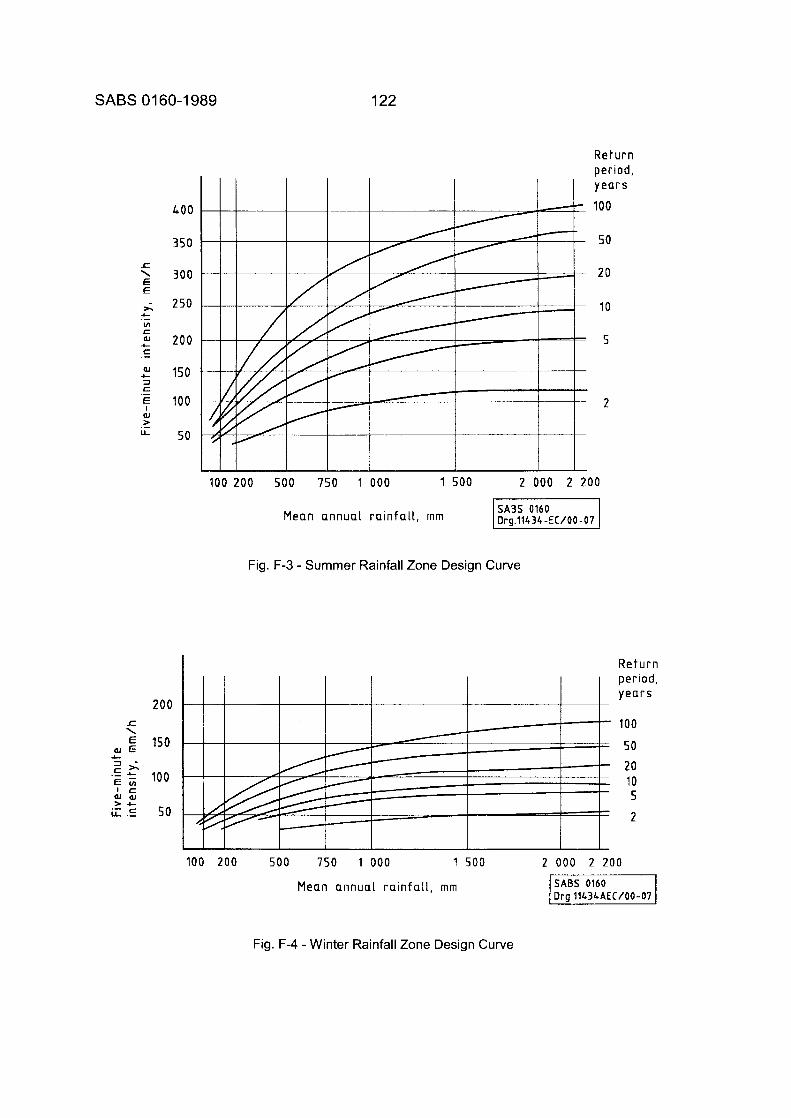
SABS 01 60-1 989 122
r \ E E
h
In c 0.l c c
(U c 3 c
L .-
.-
.- E I
(U w
L L ._
400
350
300
250
200
150
100
50
200
150
100
5 0
Return period, years
100
50
2 0
10
100 200 500 750 1 000 1 500 2 000 2 200
Mean annual rainfall, rnm
Fig. F-3 - Summer Rainfall Zone Design Curve
I I
:
I I
L Return period, yea rs
- 100
= 50
- 20 1 10 - 5 : 2
- 100 200 5 0 0 750 1 000 1 500 2 000 2 200
Mean annual rainfall, rnrn
Fig. F-4 -Winter Rainfall Zone Design Curve
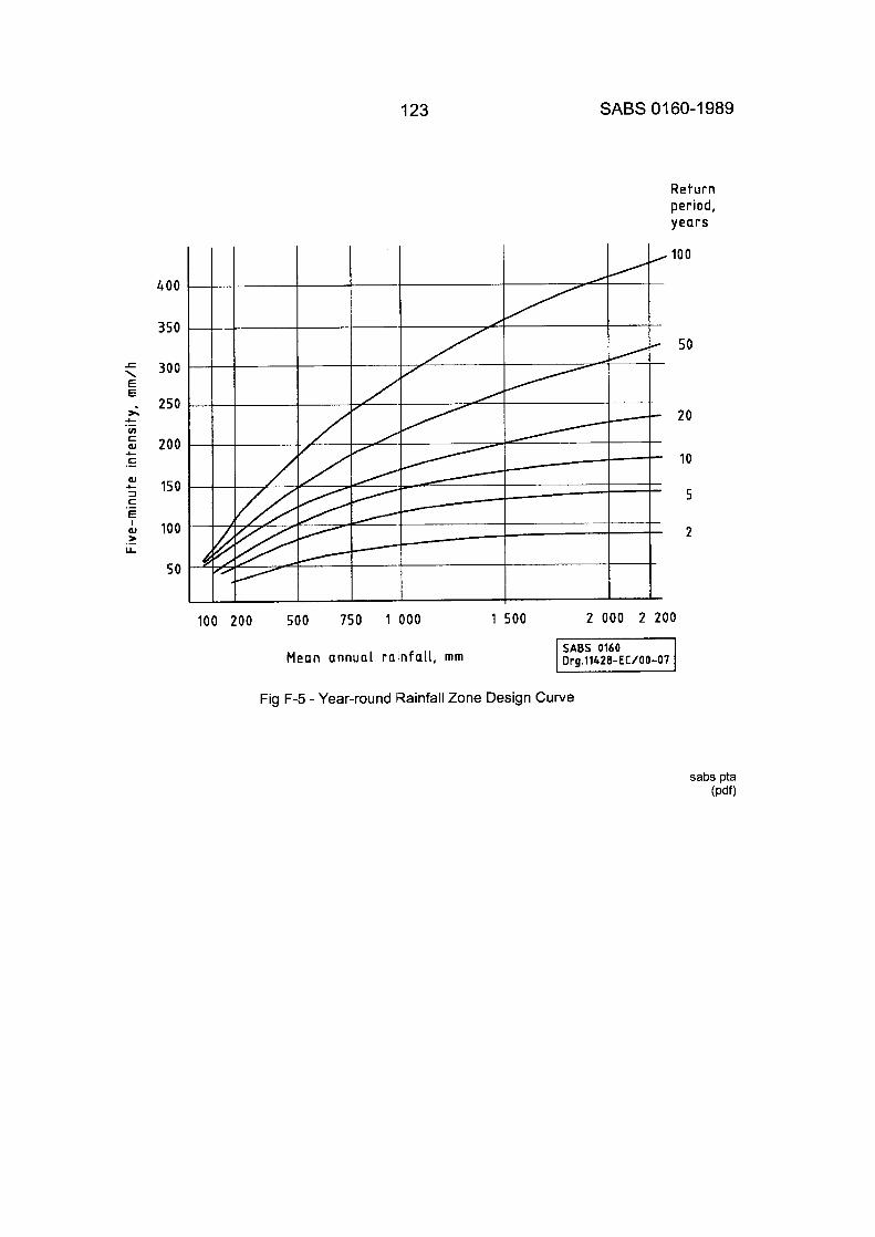
123 SABS 01 60-1 989
Return period, years
100
400
350
300
250
200
150
100
50
100 200 500 750 1 000 1 500 2 000 2 200
50
20
10
5
2
Mean annual rainfall, mm
Fig F-5 - Year-round Rainfall Zone Design Curve
sabs pta (Pdf)

