sanitary sewer design technical criteria manual - denver · pdf filesanitary sewer design...
TRANSCRIPT

March 2008 i
CITY AND COUNTY OF DENVER DEPARTMENT OF PUBLIC WORKS
SANITARY SEWER DESIGN TECHNICAL CRITERIA MANUAL
(revised March 2008)
TABLE OF CONTENTS
SECTION SUBJECT PAGE
1 GENERAL 1 1.01 INTENT OF DESIGN CRITERIA MANUAL 1 1.02 SANITARY SEWER DEPARTMENT FUNCTIONS 1 1.03 REFERENCES 2
2 SANITARY PLANNING CRITERIA 3 2.01 INTER-RELATIONSHIPS OF STUDIES AND DESIGN REPORT 3 2.02 DESIGN/PLANNING PERIOD 3 2.03 POPULATION AND LAND USE PROJECTIONS 3 2.04 SANITARY SEWER FLOW CRITERIA 4
TABLE 2.04.1- RESIDENTIAL FLOW FACTORS 6 TABLE 2.04.2 – NON-RESIDENTIAL FLOW FACTORS 7 TABLE 2.04.3 - COMMERCIAL/INDUSTRIAL FLOW FACTORS 8 TABLE 2.04.4 - PLUMBING FIXTURE UNITS 9 FIGURE 2.04.1 - PEAK FLOW FACTOR GRAPH 11 TABLE 2.04.5 - SEWAGE PEAK FLOW FACTORS 11
2.05 SANITARY SEWER FEASIBILITY STUDY (MASTER PLAN) REQUIREMENTS 12 2.06 SANITARY SEWER STUDY REQUIREMENTS 13
TABLE 2.06.1 - SANITARY SEWER COMPUTATION SHEET 16 2.07 SANITARY SEWER DESIGN REPORT REQUIREMENTS 17
TABLE 2.07.1 - GRAVITY SEWER HYDRAULIC COMPUTATIONS 18 TABLE 2.07.2 - HYDRAULIC ELEMENTS FOR CIRCULAR PIPE 19 FIGURE 2.07.1 - HYDRAULIC ELEMENTS FOR CIRCULAR PIPE 20
2.08 METERING STATIONS 21 2.09 WASTEWATER PUMPING STATIONS 21 2.10 PRIVATE SEWER SYSTEMS 23
FIGURE 2.10.1 - TERMINAL PRIVATE SEWER CLEANOUT (6” Mains only) 24 2.11 BUILDING SERVICE CONNECTIONS 25
TABLE 2.11.1 – ACCEPTABLE SERVICE CONNECTION METHODS 26 FIGURE 2.11.1 - BUILDING SEWERS SERVICE LINE CLEAN-OUT 28 FIGURE 2.11.2 - BUILDING SEWERS SERVICE AND RISER DETAIL 29
2.12 SEWER ABANDONMENTS 30 2.13 FOUNDATION DRAINS 30
FIGURE 2.13.1 – UNDERDRAIN CUT OFF WALL 32
3 DESIGN OF PUBLIC SEWERS 33 3.01 DEPTHS OF SEWERS 33 3.02 DATUM 33
March 2008 ii
3.03 BENCHMARKS 33 3.04 LOCATION AND ALIGNMENT 33 3.05 MULTIPLE PIPES IN A SINGLE TRENCH 36 3.06 HYDRAULIC DESIGN 36 3.07 SLOPE OF SEWERS 36
TABLE 3.07 - MINIMUM AND MAXIMUM SEWER SLOPES 37 3.08 MANHOLE DROPS 37 3.09 MANHOLES AND JUNCTION STRUCTURES, ETC 38 3.10 MANHOLE SPACING AND LOCATION 39 3.11 STUB-ENDS OF LINES 39 3.12 HYDRAULIC JUMPS 39 3.13 NON-UNIFORM FLOW 39 3.14 INVERTED SIPHONS 40 3.15 METER STATIONS 40 3.16 STREAM & WATER CROSSINGS 40 3.17 STRUCTURAL REQUIREMENTS 40 3.18 DESIGN PARAMETERS 40 3.19 DESIGN OF PUMPING STATION 42 3.20 OPERATIONS IN HEAVILY TRAVELED STREETS 46 3.21 TYPES OF SEWER CONSTRUCTION AND LOADING CONDITIONS 46 3.22 BACKFILL AND SPECIAL COMPACTION 46 3.23 GROUNDWATER 47 3.24 TUNNELING OF PIPELINES 47 3.25 HYDROGEN SULFIDE PRODUCTION 48
4 DESIGN DRAWINGS 50 4.01 FORMAT 50 4.02 COVER SHEET 51 4.03 PLAN/PROFILE SHEETS 51 4.04 AS BUILT DRAWINGS 53
TABLE 4.04 – CONSTRUCTION PLANS CHECK LIST 54 FIGURE 4.04 - SIGNATURE BLOCK FORMAT FOR TITLE SHEET 55
5 APPENDIX A – USEFUL FORMS 56 5.01 GRAVITY SEWER HYDRAULIC CHARACTERISTIC COMPUTATIONS FORM 56 5.02 MANHOLE & TRANSITION LOSS HYDRAULIC COMPUTATION FORM 57 5.03 BEND LOSS HYDRAULIC COMPUTATION (GRAVITY FLOW) FORM 58 5.04 CRITICAL DEPTH TABLE FOR CIRCULAR PIPES 59 5.05 HYDRAULIC ELEMENTS FOR 3x2 EGG-SHAPED PIPE 60 5.06 HYDRAULIC ELEMENTS FOR 1x1.575 HORIZONTAL ELLIPTICAL PIPE 62 5.07 HYDRAULIC ELEMENTS FOR 1x2 BOX-SHAPED PIPE 64
6 APPENDIX B – LIFT STATION DESIGN 66 6.01 SANITARY SEWAGE PUMPING STATION / FORCE MAIN 66
CITY AND COUNTY OF DENVER DEPARTMENT OF PUBLIC WORKS
SECTION 1: GENERAL
1 March 2008
1 GENERAL
1.01 INTENT OF DESIGN CRITERIA MANUAL This part of the Technical Manual summarizes and outlines policy, methods,
practice, procedures, and design standards utilized in the Department’s Public Works’ activities. The criteria are adopted to encourage consistency in the development of sanitary sewer systems in the City and County of Denver.
All previous Department of Public Works Criteria for Sanitary Sewer Design are
hereby superseded. The criteria set forth in this technical manual are intended to provide guidelines
for the design of sanitary sewers. Standardized procedures to include minimum or maximum controls are presented which relate to routine review or sewer design and construction. However, in unusual circumstances or where special conditions dictate, certain deviations from standard criteria may be approved by the Manager of Public Works provided that such deviations are documented fully and are based upon sound engineering practice.
The design engineer also must be thoroughly familiar with any and all
construction contract documents including general contract conditions, supplemental technical or detail construction specifications, and standard or special detail drawings published or otherwise issued by Denver. Therefore, use of this Criteria Manual must be considered in conjunction with the following material:
Detail and Technical Specifications for Storm Drainage and Sanitary
Sewer Construction, City & County of Denver, Public Works, Engineering Division
Standard Details, Department of Public Works, City & County of Denver, Wastewater Management Division.
1.02 SANITARY SEWER DEPARTMENT FUNCTIONS The Department of Public Works has the responsibility for all planning,
engineering design and construction associated with the Denver sanitary sewer system. Within this responsibility, it reviews and coordinates the activities of other governmental bodies, private and public firms or entities and individuals engaged in sewer design/construction. The Department also conducts inspection of the construction of the sanitary sewer system in Denver.
CITY AND COUNTY OF DENVER DEPARTMENT OF PUBLIC WORKS
SECTION 1: GENERAL
2 March 2008
1.03 REFERENCES Terms, nomenclature, and descriptive words utilized or referred to in this
Technical Manual (as well as technical reference) are as defined in the following references:
1. Chapter 56, Denver Revised Municipal Code, 2007.
2. Concrete Pipe Handbook, American Concrete Pipe Association, 1988.
3. Design and Construction of Sanitary & Storm Sewers, Water Pollution Control Federation (WPCF) Manual of Practice No. 9, 1969.
4. Design Manual: Sulfide and Corrosion Prediction and Control, American
Concrete Pipe Association, 1984.
5. Detail and Technical Specifications for Storm Drainage and Sanitary Sewer Construction, Wastewater Management Division, 2004.
6. Elwyn E. Seelye, Data Book for Civil Engineers, Vol. I, Design, 3rd Edition, 1996.
7. Gravity Sanitary Sewer Design and Construction, Second Edition, ASCE
Manuals and Reports on Engineering Practice No. 60/ WEF Manual of Practice No. FD-5, 2007.
8. International Building Code - International Code Council, 2006.
9. International Plumbing Code - International Code Council, 2006.
10. Rules and Regulations, Wastewater Management Division, 1998.
11. Sanitary Sewer Master Plan, City & County of Denver, June 2006.
12. Standard Details, Department of Public Works, City & County of Denver,
Wastewater Management Division, 1995 with updates.
13. Sulfide in Wastewater Collection and Treatment Systems, ASCE Manuals and Reports on Engineering Practice - No. 69, 1989.
CITY AND COUNTY OF DENVER DEPARTMENT OF PUBLIC WORKS
SECTION 2: SANITARY PLANNING CRITERIA
3 March 2008
2 SANITARY PLANNING CRITERIA
2.01 INTER-RELATIONSHIPS OF STUDIES AND DESIGN REPORT 2.01.1 Feasibility Study (or Master Plan) may be required at the conceptual state
of a project in order to assess the impact of providing sanitary service to a particular area or various alternates for providing such service. This report presents preliminary planning data necessary to evaluate a proposal and is less rigorous than a sanitary study as it is based on general zoning information rather than on actual development plans.
2.01.2 Sanitary Study will be required of all projects or developments tributary to
Denver's sewers and is required prior to Sewer Use and Drainage Permit Application issuance. This study details the basis for sewer design and provides the planning information necessary to assess the impact of a particular development on Denver's sanitary sewer system, as well as information on the anticipated sewage flows to include special wastes added to the system.
2.01.3 Design Report provides information on proposed major main-line sewers
to include special devices, pumps, holding tanks, etc. and may be required by the Department of Public Works prior to the review of construction plans. The data presented in the report will aid in the review of construction plans and provide justification to support the design proposed.
2.01.4 The submission of a feasibility study does not substitute for the sanitary
study requirement but may be done if the detailed data required by a sanitary study is not available in the earlier stages of planning. Eventually, a detailed sanitary study must be submitted prior to the approval of construction plans or issuance of a Sewer Use and Drainage Permit Application.
2.02 DESIGN/PLANNING PERIOD All improvements to the sanitary system shall be planned and designed to
provide adequate service for a design horizon of 50 years unless a longer or shorter useful life period is stipulated or allowed by the Department of Public Works.
When allowed or stipulated by the Department of Public Works, proposed
improvements may be staged over a period of time (e.g., the pumping capacity of a lift station may be staged to match development rather than initially set at the future rate).
2.03 POPULATION AND LAND USE PROJECTIONS 2.03.1 Land use plans serve as a first step in setting up zones for various
classifications of residential, commercial and industrial use. They are adopted as an official expression of intent; however, they do not have the legal status of zoning and are subject to revision in the light of changing conditions and outlook. Contact the Zoning Administration or see the

CITY AND COUNTY OF DENVER DEPARTMENT OF PUBLIC WORKS
SECTION 2: SANITARY PLANNING CRITERIA
4 March 2008
website DENVERGOV.ORG → CITY PLANNING → ZONING INFORMATION → ZONE DISTRICTS AND DEFINITIONS for a description of various zoning classifications in use in Denver.
http://www.denvergov.org/Zoning/ZoneDistrictDescriptions/tabid/396290/Default.aspx
2.03.2 Land use maps to be used for the design period may be obtained from the
Denver Community Planning and Development Agency. Additionally, coordination with the regional land use data base established by the Denver Regional Council of Governments (DRCOG) is suggested.
2.03.3 Current zoning or projected land use classifications for planning areas
shall be used in planning for the projected sanitary sewage flow as determined using the criteria contained in Section 2.03. Projected population and land use (as presented in the Denver Comprehensive Plan or DRCOG projections) shall be used to develop sewage flow projections for large planning areas.
2.03.4 Computations of population for the tributary residential land use areas are
based on the estimated population density (See Table 2.04.1). Forecasts of population and economic activity for individual small areas should be consistent with regional plans.
2.04 SANITARY SEWER FLOW CRITERIA 2.04.1 Residential, average flow rates shall be based on: a. The number of units served, b. The population densities for each residential land use or zone listed in
Table 2.04.1, and c. A per capita flow rate of 120 GPD In the case of a conceptual study, the average flow rate may be based on
the per acre flows listed in Table 2.04.1 for each land use. 2.04.2 Industrial and commercial average sewage flow rates shall be based on a
per acre average daily flow for each land use or zone as listed in Table 2.04.2.
2.04.3 The relationship of the peak flow to average flow is given in Figure 2.04.1
and Table 2.04.5. Peak flow, along with maximum infiltration, shall determine the hydraulic capacity of sewers in all cases.
2.04.4 Infiltration/Inflow (I/I) rate shall be 500 gallons per gross acre of tributary
area per day. This infiltration/inflow value is a design figure for average
conditions expected during the service life of sanitary sewers. High groundwater tables, poor soil conditions, or any other unusual conditions may call for a special study of other infiltration/inflow and its affect on sewer capacity.
CITY AND COUNTY OF DENVER DEPARTMENT OF PUBLIC WORKS
SECTION 2: SANITARY PLANNING CRITERIA
5 March 2008
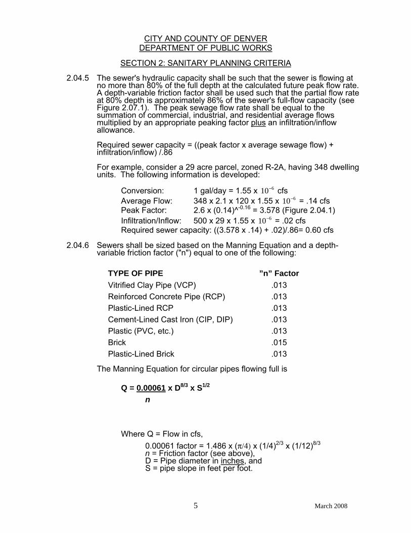
2.04.5 The sewer's hydraulic capacity shall be such that the sewer is flowing at no more than 80% of the full depth at the calculated future peak flow rate. A depth-variable friction factor shall be used such that the partial flow rate at 80% depth is approximately 86% of the sewer's full-flow capacity (see Figure 2.07.1). The peak sewage flow rate shall be equal to the summation of commercial, industrial, and residential average flows multiplied by an appropriate peaking factor plus an infiltration/inflow allowance.
Required sewer capacity = ((peak factor x average sewage flow) + infiltration/inflow) /.86
For example, consider a 29 acre parcel, zoned R-2A, having 348 dwelling
units. The following information is developed: Conversion: 1 gal/day = 1.55 x 10 6− cfs
Average Flow: 348 x 2.1 x 120 x 1.55 x 10 6− = .14 cfs Peak Factor: 2.6 x (0.14)^-0.16 = 3.578 (Figure 2.04.1) Infiltration/Inflow: 500 x 29 x 1.55 x 10 6− = .02 cfs Required sewer capacity: ((3.578 x .14) + .02)/.86= 0.60 cfs
2.04.6 Sewers shall be sized based on the Manning Equation and a depth-
variable friction factor ("n") equal to one of the following:
TYPE OF PIPE ”n” Factor Vitrified Clay Pipe (VCP) .013 Reinforced Concrete Pipe (RCP) .013 Plastic-Lined RCP .013 Cement-Lined Cast Iron (CIP, DIP) .013 Plastic (PVC, etc.) .013 Brick .015 Plastic-Lined Brick .013
The Manning Equation for circular pipes flowing full is Q = 0.00061 x D8/3 x S1/2 n Where Q = Flow in cfs,
0.00061 factor = 1.486 x (π/4) x (1/4)2/3 x (1/12)8/3 n = Friction factor (see above), D = Pipe diameter in inches, and S = pipe slope in feet per foot.

CITY AND COUNTY OF DENVER DEPARTMENT OF PUBLIC WORKS
SECTION 2: SANITARY PLANNING CRITERIA
6 March 2008
TABLE 2.04.1- RESIDENTIAL FLOW FACTORS
CRITERIA LAND USE
DENSITY ZONE DEFINITION APPROXIMATE BLUEPRINT
DENVER LAND USE
Units per
Acre
Population per Unit
Gallons per Net
Acre per Day*
SFR Low RS4 Single-Unit Detached Dwellings, Suburban Density
2.7 3.1 1000
SFR Medium RX Attached or Clustered Single-Unit Dwellings, Low Density
4 3.1 1500
SFR High R0 Single-Unit Detached Dwellings, Low Density
Single Family Residential
6 2.8 2000
R1 Single-Unit Detached Dwellings, Low Density
MFR Low R2 Multi-Unit Dwellings, Low Density
6 2.8 2000
MFR Medium R2A Multi-Unit Dwellings, Medium Density
Single Family Duplex
12 2.1 3000
R2B Multi-Unit Dwellings, Medium Density
R3X Multi-Unit Dwellings, Medium Density
MFR High R3 Multi-Unit Dwellings, High Density
Urban Residential 24 2.1 6000
R4 Multi-Unit Dwellings and/or Offices, High Density
R4X Multi-Unit Dwellings and/or Offices, High Density
RMU-20 Residential Mixed Use MFR Very High RMU-30 Residential Mixed Use 100 2.0 24000
SFR = Single-Family Residential MFR = Multi-Family Residential *Based on ‘Net’ Area. Gross Area = Net Area + Right-of-Way. GPAD for net area = GPAD for gross area / 1.25 (i.e. Net area is adjusted downward from gross area by 125%)
CITY AND COUNTY OF DENVER DEPARTMENT OF PUBLIC WORKS
SECTION 2: SANITARY PLANNING CRITERIA
7 March 2008
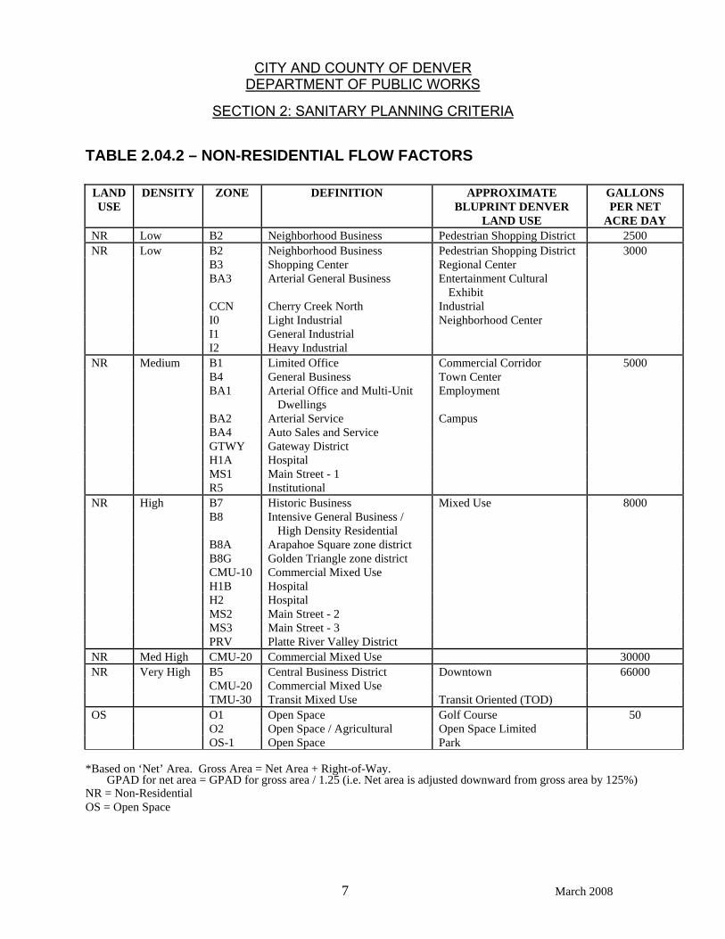
TABLE 2.04.2 – NON-RESIDENTIAL FLOW FACTORS
LAND USE
DENSITY ZONE DEFINITION APPROXIMATE BLUPRINT DENVER
LAND USE
GALLONS PER NET
ACRE DAY NR Low B2 Neighborhood Business Pedestrian Shopping District 2500 NR Low B2 Neighborhood Business Pedestrian Shopping District 3000 B3 Shopping Center Regional Center
BA3 Arterial General Business Entertainment Cultural
Exhibit
CCN Cherry Creek North Industrial I0 Light Industrial Neighborhood Center I1 General Industrial I2 Heavy Industrial NR Medium B1 Limited Office Commercial Corridor 5000 B4 General Business Town Center
BA1 Arterial Office and Multi-Unit
Dwellings Employment
BA2 Arterial Service Campus BA4 Auto Sales and Service GTWY Gateway District H1A Hospital MS1 Main Street - 1 R5 Institutional NR High B7 Historic Business Mixed Use 8000 B8 Intensive General Business /
High Density Residential
B8A Arapahoe Square zone district B8G Golden Triangle zone district CMU-10 Commercial Mixed Use H1B Hospital H2 Hospital MS2 Main Street - 2 MS3 Main Street - 3 PRV Platte River Valley District NR Med High CMU-20 Commercial Mixed Use 30000 NR Very High B5 Central Business District Downtown 66000 CMU-20 Commercial Mixed Use TMU-30 Transit Mixed Use Transit Oriented (TOD) OS O1 Open Space Golf Course 50 O2 Open Space / Agricultural Open Space Limited OS-1 Open Space Park
*Based on ‘Net’ Area. Gross Area = Net Area + Right-of-Way. GPAD for net area = GPAD for gross area / 1.25 (i.e. Net area is adjusted downward from gross area by 125%) NR = Non-Residential OS = Open Space
CITY AND COUNTY OF DENVER DEPARTMENT OF PUBLIC WORKS
SECTION 2: SANITARY PLANNING CRITERIA
8 March 2008
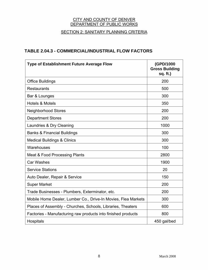
TABLE 2.04.3 - COMMERCIAL/INDUSTRIAL FLOW FACTORS
Type of Establishment Future Average Flow (GPD/1000 Gross Building
sq. ft.)
Office Buildings 200
Restaurants 500
Bar & Lounges 300
Hotels & Motels 350
Neighborhood Stores 200
Department Stores 200
Laundries & Dry Cleaning 1000
Banks & Financial Buildings 300
Medical Buildings & Clinics 300
Warehouses 100
Meat & Food Processing Plants 2800
Car Washes 1900
Service Stations 20
Auto Dealer, Repair & Service 150
Super Market 200
Trade Businesses - Plumbers, Exterminator, etc. 200
Mobile Home Dealer, Lumber Co., Drive-In Movies, Flea Markets 300
Places of Assembly - Churches, Schools, Libraries, Theaters 600
Factories - Manufacturing raw products into finished products 800
Hospitals 450 gal/bed
CITY AND COUNTY OF DENVER DEPARTMENT OF PUBLIC WORKS
SECTION 2: SANITARY PLANNING CRITERIA
9 March 2008
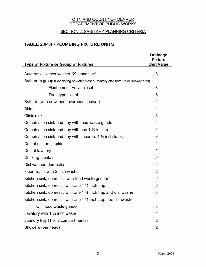
TABLE 2.04.4 - PLUMBING FIXTURE UNITS Type of Fixture or Group of Fixtures
Drainage Fixture
Unit Value Automatic clothes washer (2” standpipe) 3
Bathroom group (Consisting of water closet, lavatory and bathtub or shower stall)
Flushometer valve closet 8
Tank type closet 6
Bathtub (with or without overhead shower) 2
Bidet 1
Clinic sink 6
Combination sink and tray with food waste grinder 4
Combination sink and tray with one 1 ½ inch trap 2
Combination sink and tray with separate 1 ½ inch traps 3
Dental unit or cuspidor 1
Dental lavatory 1
Drinking fountain ½
Dishwasher, domestic 2
Floor drains with 2 inch waste 2
Kitchen sink, domestic, with food waste grinder 2
Kitchen sink, domestic with one 1 ½ inch trap 2
Kitchen sink, domestic with one 1 ½ inch trap and dishwasher 3
Kitchen sink, domestic with one 1 ½-inch trap and dishwasher
with food waste grinder 3
Lavatory with 1 ¼ inch waste 1
Laundry tray (1 or 2 compartments) 2
Showers (per head) 2
CITY AND COUNTY OF DENVER DEPARTMENT OF PUBLIC WORKS
SECTION 2: SANITARY PLANNING CRITERIA
10 March 2008
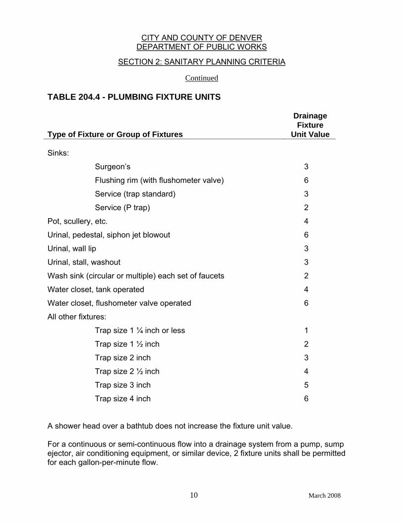
Continued TABLE 204.4 - PLUMBING FIXTURE UNITS Type of Fixture or Group of Fixtures
Drainage Fixture
Unit Value
Sinks:
Surgeon’s 3
Flushing rim (with flushometer valve) 6
Service (trap standard) 3
Service (P trap) 2
Pot, scullery, etc. 4
Urinal, pedestal, siphon jet blowout 6
Urinal, wall lip 3
Urinal, stall, washout 3
Wash sink (circular or multiple) each set of faucets 2
Water closet, tank operated 4
Water closet, flushometer valve operated 6
All other fixtures:
Trap size 1 ¼ inch or less 1
Trap size 1 ½ inch 2
Trap size 2 inch 3
Trap size 2 ½ inch 4
Trap size 3 inch 5
Trap size 4 inch 6
A shower head over a bathtub does not increase the fixture unit value. For a continuous or semi-continuous flow into a drainage system from a pump, sump ejector, air conditioning equipment, or similar device, 2 fixture units shall be permitted for each gallon-per-minute flow.
CITY AND COUNTY OF DENVER DEPARTMENT OF PUBLIC WORKS
SECTION 2: SANITARY PLANNING CRITERIA
11 March 2008
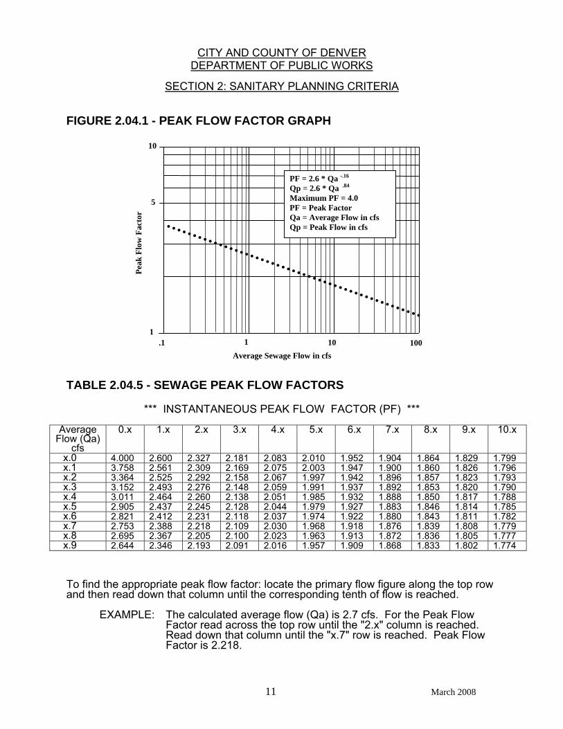
FIGURE 2.04.1 - PEAK FLOW FACTOR GRAPH
TABLE 2.04.5 - SEWAGE PEAK FLOW FACTORS
*** INSTANTANEOUS PEAK FLOW FACTOR (PF) ***
Average Flow (Qa)
cfs
0.x 1.x 2.x 3.x 4.x 5.x 6.x 7.x 8.x 9.x 10.x
x.0 4.000 2.600 2.327 2.181 2.083 2.010 1.952 1.904 1.864 1.829 1.799 x.1 3.758 2.561 2.309 2.169 2.075 2.003 1.947 1.900 1.860 1.826 1.796 x.2 3.364 2.525 2.292 2.158 2.067 1.997 1.942 1.896 1.857 1.823 1.793 x.3 3.152 2.493 2.276 2.148 2.059 1.991 1.937 1.892 1.853 1.820 1.790 x.4 3.011 2.464 2.260 2.138 2.051 1.985 1.932 1.888 1.850 1.817 1.788 x.5 2.905 2.437 2.245 2.128 2.044 1.979 1.927 1.883 1.846 1.814 1.785 x.6 2.821 2.412 2.231 2.118 2.037 1.974 1.922 1.880 1.843 1.811 1.782 x.7 2.753 2.388 2.218 2.109 2.030 1.968 1.918 1.876 1.839 1.808 1.779 x.8 2.695 2.367 2.205 2.100 2.023 1.963 1.913 1.872 1.836 1.805 1.777 x.9 2.644 2.346 2.193 2.091 2.016 1.957 1.909 1.868 1.833 1.802 1.774
To find the appropriate peak flow factor: locate the primary flow figure along the top row and then read down that column until the corresponding tenth of flow is reached. EXAMPLE: The calculated average flow (Qa) is 2.7 cfs. For the Peak Flow
Factor read across the top row until the "2.x" column is reached. Read down that column until the "x.7" row is reached. Peak Flow Factor is 2.218.
Peak
Flo
w F
acto
r
5
10
1 .1 1 10 100
Average Sewage Flow in cfs
PF = 2.6 * Qa -.16 Qp = 2.6 * Qa .84 Maximum PF = 4.0 PF = Peak Factor Qa = Average Flow in cfs Qp = Peak Flow in cfs
CITY AND COUNTY OF DENVER DEPARTMENT OF PUBLIC WORKS
SECTION 2: SANITARY PLANNING CRITERIA
12 March 2008
2.05 SANITARY SEWER FEASIBILITY STUDY (MASTER PLAN) REQUIREMENTS 2.05.1 A feasibility study shall be submitted in cases in where it is: a. Required by the Department of Public Works in order to determine the
feasibility of, or alternates for, providing sanitary service to a particular area, or
b. Desired by the developer/engineer to present to the Department of
Public Works a concept for providing sanitary service to a particular area.
2.05.2 The study must be prepared by a Professional Engineer, currently
registered in the State of Colorado, whose seal and signature shall be affixed to it.
2.05.3 The narrative description of the project shall include: a. Name, address, and location of project. b. Adjacent street names. c. Legal description and/or vicinity map of site. d. Existing or proposed zoning and land use for both the project area and
adjacent areas. e. Type and size of development: i) Residential – area and land use or, if known, number of units and
projected population using this criteria. ii) Industrial or commercial – area and land use. 2.05.4 The study shall be accompanied by a vicinity map (suggested scale: 1" =
1000') which should include the following: a. Geographic location of site. b. Relationship to major arterial streets. c. Any other landmarks that may be helpful with site identification. 2.05.5 The flow calculations shall include the following information for each
alternate considered: a. The quantity (average and peak) of sewage flow expected to be
generated by the project using current Department of Public Works design criteria.
b. The nature of wastes if not ordinary domestic sewage. c. The expected design point to design point flows in arterial sewers (i.e.,
those major sewers greater than 8 inches in diameter as well as those
CITY AND COUNTY OF DENVER DEPARTMENT OF PUBLIC WORKS
SECTION 2: SANITARY PLANNING CRITERIA
13 March 2008
which are expected to serve more than one phase or filing of the proposed development) shall be tabulated using the form in Table 2.06.1 or a similar form.
d. In addition to the quantity of flow generated within a project, the impact
of the project's expected peak flow on the sewer system downstream, from the point of connection to the first significant outfall, shall be investigated to ensure that adequate capacity is available not only for the proposed project, but for all present users of the existing public sanitary sewer system. Unless otherwise determined by the Department of Public Works, a significant outfall shall be considered to be any sewer or series of sewers which is continuously 10 inches, or greater, in diameter from the point in question to the sewage treatment plant.
e. If future development upstream of the project is anticipated, the
estimated peak flow from such development is to be computed and routed through the project to assess the impacts of such flows on the entire system to the point demarking the first significant outfall sewer. The Sanitary Sewer Master Plan (latest edition) may be consulted for this information.
f. The study should address the selection and evaluation of alternates, as
well as phasing, and make recommendations as to the best plan to be selected for implementation.
2.05.6 Additional requirements may be added by the Department of Public Works
in order to address special circumstances.
2.05.7 Any changes to the project which result in a revision of the information presented in the study shall be addressed in an amendment to the original feasibility study.
2.05.8 A site plan (1" = 200' suggested scale) which shall include: a. Study area boundaries. b. Proposed major sewer lines (i.e., those serving more than one phase or
filing of any off-site area) c. Sub-area boundaries. d. A clear indication of how the sewage from each sub-area is to be
conveyed to a proposed or existing major sewer. 2.06 SANITARY SEWER STUDY REQUIREMENTS 2.06.1 A sanitary study shall be submitted for all developments tributary to the
Denver sewage collection system unless this requirement is waived by the Department of Public Works.
2.06.2 The study will be prepared by a Professional Engineer, currently
registered in the State of Colorado, whose seal and signature shall be affixed to it.
CITY AND COUNTY OF DENVER DEPARTMENT OF PUBLIC WORKS
SECTION 2: SANITARY PLANNING CRITERIA
14 March 2008
2.06.3 The narrative section shall include: a. Name, address, and location of project. b. Adjacent street names. c. Legal description of site. d. Existing or proposed zoning and land use for both the project and
adjacent areas. e. Type and size of development: i) Residential - Number of units and projected population using this
criteria. ii) Industrial or Commercial - Building use, and floor space (if known,
otherwise, land use and parcel area). 2.06.4 A vicinity map (1" = 1,000' suggested scale) shall accompany the study
and include: a. Geographic location of site. b. Relationship to major arterial streets. c. Any other landmarks that may be helpful. 2.06.5 The site map (1" = 50' suggested scale, or 1" = 100' for larger projects)
shall include: a. Lot lines and dimensions. b. Existing and proposed contours at two foot intervals. c. Sanitary sewer manhole inverts and rim elevations. d. Street names. e. Easement and right-of-way dimensions. f. Location of curbs and sidewalks. g. Existing and proposed utilities (with storm and sanitary connections and
appurtenances) dimensioned from the property lines. h. Sub-area boundaries for each design point studied on the existing or
proposed sewer system.
CITY AND COUNTY OF DENVER DEPARTMENT OF PUBLIC WORKS
SECTION 2: SANITARY PLANNING CRITERIA
15 March 2008
2.06.6 The flow calculations shall include: a. The quantity (average, peak and infiltration) of sewage flow expected to
be generated by the project using this criteria calculated for each point of connection to the existing or proposed sewer system.
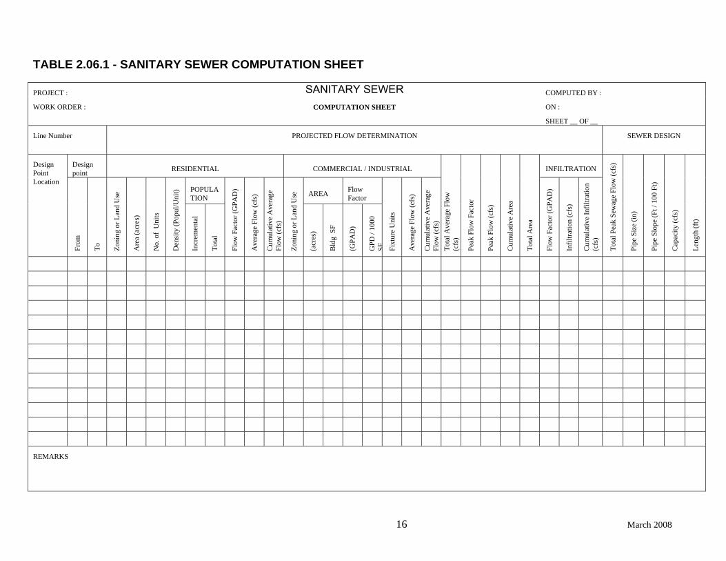
b. For all proposed main-line sewers (at each design point), a tabulation of
the expected flows (including upstream flows, see Section 2.06.6f below) using the form illustrated in Table 2.06.1 (or a similar form).
c. The nature of wastes if not ordinary domestic sewage.
d. The quantity and type of discharge of an unusual nature (e.g.,
swimming pool drainage, cooling water, commercial discharges, floor drains from auto repair garages, steam cleaning, chemical, dairy, food processing or service, car washes, metal treating or plating operations, etc.)
e. In addition to the quantity of flow generated within a project, the impact
of the project's expected peak flow on the sewer system downstream, from the point of connection to the first significant outfall, shall be investigated to ensure that adequate capacity is available not only for the proposed project, but for all present users of the existing public sanitary sewer system. Unless otherwise determined by the Department of Public Works, a significant outfall shall be considered to be any sewer or series of sewers which is continuously 10 inches, or greater, in diameter from the point in question to the sewage treatment plant.
f. If future development upstream of the project is anticipated, the
estimated peak flow from such development is to be separately computed and routed through the project and existing system to assess the impacts of such flows on the entire system to the point demarking the first significant outfall sewer. The Sanitary Sewer Master Plan (latest edition) may be consulted for this information.
g. As required, the study should address the selection and evaluation of
alternates, as well as phasing, and make recommendations as to the best plan to be selected for implementation.
2.06.7 Additional requirements may be added by the Department of Public Works
in order to address special circumstances. 2.06.8 Any changes to the project which result in a revision of the information
presented in the sanitary study shall be addressed in an amendment to the study.
16 March 2008
TABLE 2.06.1 - SANITARY SEWER COMPUTATION SHEET
PROJECT : SANITARY SEWER COMPUTED BY :
WORK ORDER : COMPUTATION SHEET ON :
SHEET __ OF __
Line Number
PROJECTED FLOW DETERMINATION SEWER DESIGN
Design point RESIDENTIAL COMMERCIAL / INDUSTRIAL INFILTRATION
POPULATION AREA Flow
Factor
Design Point Location
From
To
Zoni
ng o
r Lan
d U
se
Are
a (a
cres
)
No.
of
Uni
ts
Den
sity
(Pop
ul/U
nit)
Incr
emen
tal
Tota
l
Flow
Fac
tor (
GPA
D)
Ave
rage
Flo
w (c
fs)
Cum
ulat
ive
Ave
rage
Fl
ow (c
fs)
Zoni
ng o
r Lan
d U
se
(acr
es)
Bld
g S
F
(GPA
D)
GPD
/ 10
00
SF Fixt
ure
Uni
ts
Ave
rage
Flo
w (c
fs)
Cum
ulat
ive
Ave
rage
Fl
ow (c
fs)
Tota
l Ave
rage
Flo
w
(cfs
)
Peak
Flo
w F
acto
r
Peak
Flo
w (c
fs)
Cum
ulat
ive
Are
a
Tota
l Are
a
Flow
Fac
tor (
GPA
D)
Infil
tratio
n (c
fs)
Cum
ulat
ive
Infil
tratio
n (c
fs)
Tota
l Pea
k Se
wag
e Fl
ow (c
fs)
Pipe
Siz
e (in
)
Pipe
Slo
pe (F
t / 1
00 F
t)
Cap
acity
(cfs
)
Leng
th (f
t)
REMARKS
CITY AND COUNTY OF DENVER DEPARTMENT OF PUBLIC WORKS
SECTION 2: SANITARY PLANNING CRITERIA
17 March 2008
2.07 SANITARY SEWER DESIGN REPORT REQUIREMENTS 2.07.1 At the discretion of the Department of Public Works, a design report may
be required to be submitted with all major (generally greater than 8 inches in diameter) main-line sanitary sewer construction plans.
2.07.2 The report must be prepared by a Professional Engineer, registered in the
State of Colorado, whose seal and signature shall be affixed to the report. 2.07.3 The report shall consist of: a. A narrative description of the project. b. A vicinity map showing the location of the project (1" = 1000' suggested
scale). c. A tabulation of the number of manholes and length of sewers of various
sizes to be used in the project. d. A tabulation of sewer design flow conditions during "ultimate" periods
for both average and peak flow using a form similar to that shown in Table 2.06.1 (Figure 2.07.1 should be utilized in the calculation of sewer hydraulics at conditions less than full flow).
e. Hydrogen sulfide production calculations, as required. f. Calculations which pertain to metering stations, pump stations, or
special structures (see Sections 2.08 and 2.09). g. Hydraulic grade-line calculations for sewers 24 inches in diameter and
greater which shall be presented as a line plotted on the sewer line profile drawing.
h. An estimate of the cost of design and construction of the sewer system. 2.07.4 These requirements may be varied by addition or deletion at the discretion
of the Department of Public Works. 2.07.5 The design report shall be incorporated into a sanitary study and/or
submitted prior to the construction plans. 2.07.6 Any changes in the construction plans must be addressed in a revision to
the design report.
18 March 2008
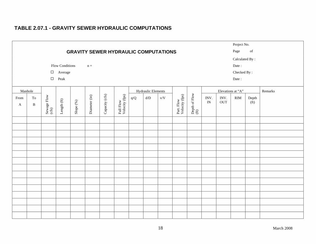
TABLE 2.07.1 - GRAVITY SEWER HYDRAULIC COMPUTATIONS
Project No.
GRAVITY SEWER HYDRAULIC COMPUTATIONS Page of
Calculated By :
Flow Conditions n = Date :
Average Checked By :
Peak Date :
Manhole Hydraulic Elements Elevations at “A”
From
A
To
B
Sew
age
Flow
(c
fs)
Leng
th (f
t)
Slop
e (%
)
Dia
met
er (i
n)
Cap
acity
(cfs
)
Full
Flow
V
eloc
ity (f
ps)
q/Q d/D v/V
Part.
Flo
w
Vel
ocity
(fps
)
Dep
th o
f Flo
w
(ft)
INV. IN
INV. OUT
RIM Depth (ft)
Remarks
CITY AND COUNTY OF DENVER DEPARTMENT OF PUBLIC WORKS
SECTION 2: SANITARY PLANNING CRITERIA
19 March 2008
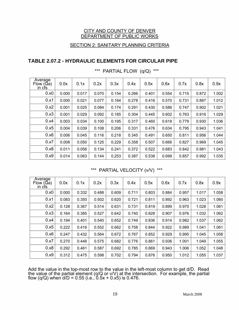
TABLE 2.07.2 - HYDRAULIC ELEMENTS FOR CIRCULAR PIPE
*** PARTIAL FLOW (q/Q) ***
Average Flow (Qa)
in cfs 0.0x 0.1x 0.2x 0.3x 0.4x 0.5x 0.6x 0.7x 0.8x 0.9x
0.x0 0.000 0.017 0.070 0.154 0.266 0.401 0.554 0.715 0.872 1.002
0.x1 0.000 0.021 0.077 0.164 0.278 0.416 0.570 0.731 0.887 1.012
0.x2 0.001 0.025 0.084 0.174 0.291 0.430 0.586 0.747 0.902 1.021
0.x3 0.001 0.029 0.092 0.185 0.304 0.445 0.602 0.763 0.916 1.029
0.x4 0.003 0.034 0.100 0.195 0.317 0.460 0.618 0.779 0.930 1.036
0.x5 0.004 0.039 0.108 0.206 0.331 0.476 0.634 0.795 0.943 1.041
0.x6 0.006 0.045 0.116 0.218 0.345 0.491 0.650 0.811 0.956 1.044
0.x7 0.008 0.050 0.125 0.229 0.358 0.507 0.666 0.827 0.969 1.045
0.x8 0.011 0.056 0.134 0.241 0.372 0.522 0.683 0.842 0.981 1.043
0.x9 0.014 0.063 0.144 0.253 0.387 0.538 0.699 0.857 0.992 1.035
*** PARTIAL VELOCITY (v/V) ***
Average Flow (Qa)
in cfs 0.0x 0.1x 0.2x 0.3x 0.4x 0.5x 0.6x 0.7x 0.8x 0.9x
0.x0 0.000 0.332 0.488 0.609 0.711 0.803 0.884 0.957 1.017 1.058
0.x1 0.083 0.350 0.502 0.620 0.721 0.811 0.892 0.963 1.023 1.060
0.x2 0.128 0.367 0.514 0.631 0.731 0.819 0.899 0.970 1.028 1.061
0.x3 0.164 0.385 0.527 0.642 0.740 0.828 0.907 0.976 1.032 1.062
0.x4 0.194 0.401 0.540 0.652 0.749 0.836 0.914 0.982 1.037 1.062
0.x5 0.222 0.416 0.552 0.662 0.758 0.844 0.922 0.989 1.041 1.061
0.x6 0.247 0.432 0.564 0.672 0.767 0.852 0.929 0.995 1.045 1.058
0.x7 0.270 0.446 0.575 0.682 0.776 0.861 0.936 1.001 1.049 1.055
0.x8 0.292 0.461 0.587 0.692 0.785 0.869 0.943 1.006 1.052 1.048
0.x9 0.312 0.475 0.598 0.702 0.794 0.876 0.950 1.012 1.055 1.037 Add the value in the top-most row to the value in the left-most column to get d/D. Read the value of the partial element (q/Q or v/V) at the intersection. For example, the partial flow (q/Q) when d/D = 0.55 (i.e., 0.5x + 0.x5) is 0.476.
CITY AND COUNTY OF DENVER DEPARTMENT OF PUBLIC WORKS
SECTION 2: SANITARY PLANNING CRITERIA
20 March 2008
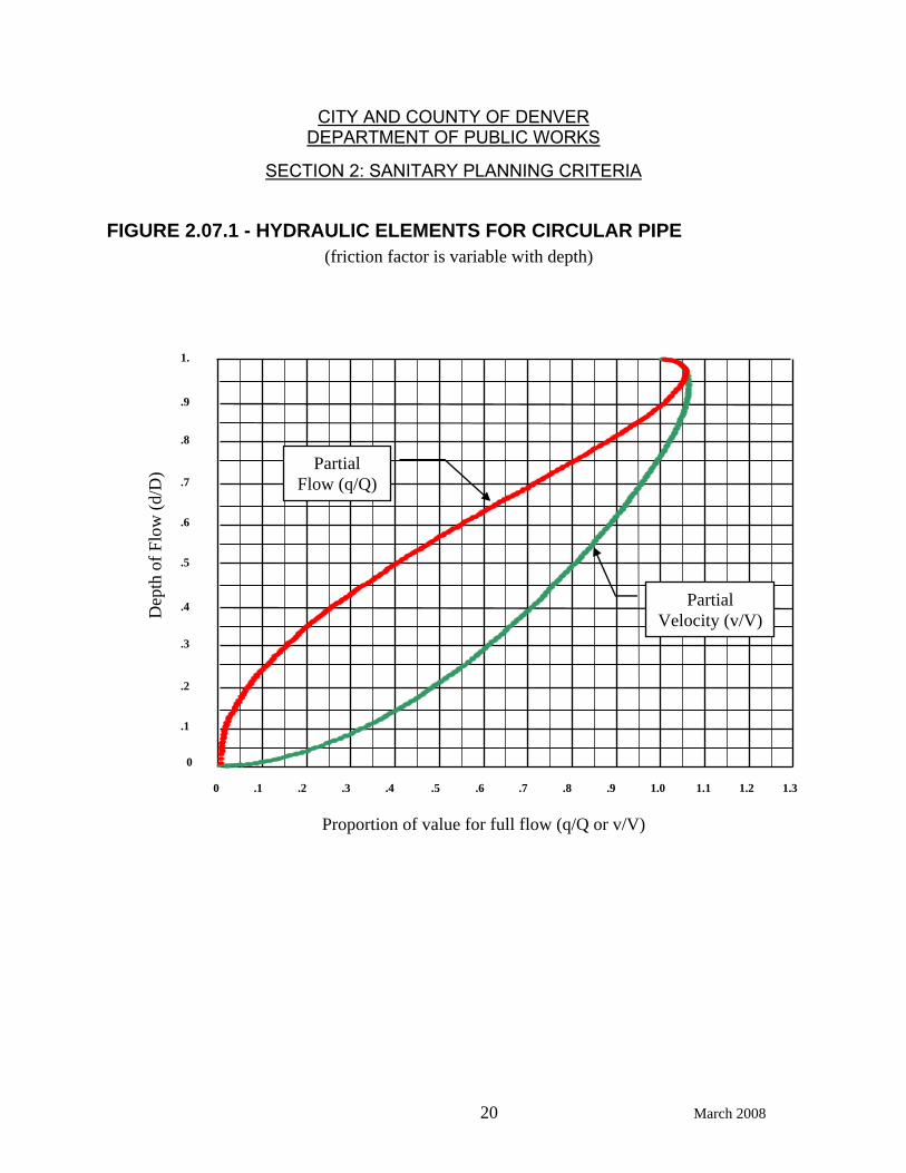
FIGURE 2.07.1 - HYDRAULIC ELEMENTS FOR CIRCULAR PIPE (friction factor is variable with depth)
0 .2 .3 .4 .5 .1 .6 .8 .9 1.0 1.1 .7 1.3 1.2
Proportion of value for full flow (q/Q or v/V)
0
1.
.9
.8
.7
.6
.5
.4
.3
.2
.1
Dep
th o
f Flo
w (d
/D) Partial
Flow (q/Q)
Partial Velocity (v/V)

CITY AND COUNTY OF DENVER DEPARTMENT OF PUBLIC WORKS
SECTION 2: SANITARY PLANNING CRITERIA
21 March 2008
2.08 METERING STATIONS 2.08.1 Metering stations which monitor sanitary sewage flow rates may be
required to be sited in locations determined by the Department of Public Works. Metering stations may be required at:
a. Points of connection between sewers owned by the City and County of
Denver (CCD) and those not owned by the CCD. b. Points of connection to major outfall sewers, and c. Other locations as determined by the Department of Public Works. 2.08.2 Any metering station design shall provide for accurate measurement of the
sewage flows expected during the design life of the station (e.g. fifty years).
2.08.3 Should a metering station be required, a sanitary study shall be submitted
to the Department of Public Works. Beyond the normal requirements, the study shall contain a description of the proposed metering station including:
a. Type of metering pit. b. Type and size of flow measuring device(s). c. Accurate range of measuring device(s). d. Type and range of recording device(s), if any, and e. The expected minimum, average, and peak sanitary sewage discharge
rates for both initial and future conditions. 2.09 WASTEWATER PUMPING STATIONS ** See Appendix A for a suggested review / summary form ** Wastewater pumping stations will only be employed when gravity flow is not
feasible; otherwise pump stations will not be afforded planning consideration. 2.09.1 Should a pumping station be a design consideration, a detailed
engineering report shall be submitted to the Department of Public Works and shall include the following:
a. A brief description of the project and purpose, and b. A pumping station "feasibility study" which provides justification.
CITY AND COUNTY OF DENVER DEPARTMENT OF PUBLIC WORKS
SECTION 2: SANITARY PLANNING CRITERIA
22 March 2008
2.09.2 The design report shall elaborate on the following for both present and
future conditions: a. Design period. b. Population densities per acre and total population. c. Areas served in acres. d. Per capita sewage contribution - average and maximum. e. Infiltration. f. Commercial and industrial waste contributions.
g. Design flow rates - average and maximum. h. Strength of sewage and industrial waste. 2.09.3 The report shall address the following for both initial and ultimate
conditions: a. Number, type, capacity, motor horsepower and Net Positive Suction
Head (NPSH) requirements of proposed pumping units. b. System head curve (including head computations) for the pumping
system. c. System head calculations shall include the size, number and length of
force main(s) and assumed C (Friction) factor. d. Sewage detention time in the wet well and force main.

CITY AND COUNTY OF DENVER DEPARTMENT OF PUBLIC WORKS
SECTION 2: SANITARY PLANNING CRITERIA
23 March 2008
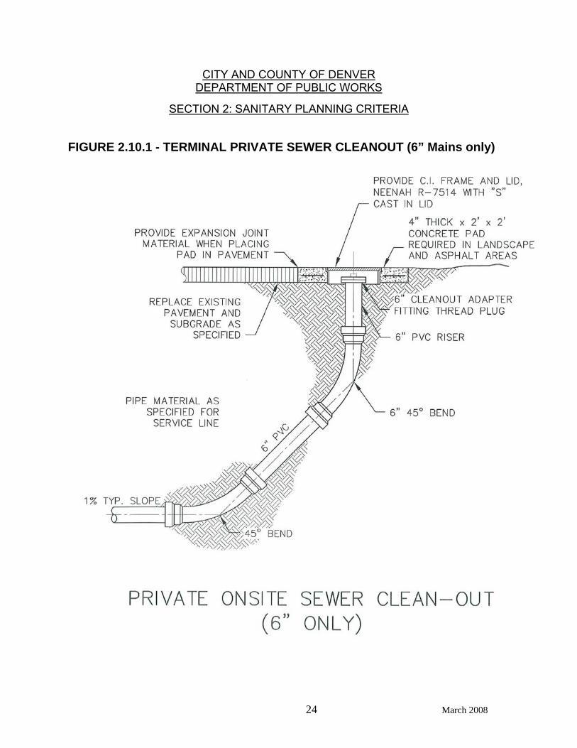
2.10 PRIVATE SEWER SYSTEMS Sewers within the City and County of Denver will be public lines except for:
Individual service connections, Taps, or Onsite sewer systems serving only the private development
2.10.1 In accordance with the Rules and Regulations (2.01, 5.02 and 9.01(f)), a
separate, independent, and unextended building sewer service must be provided for every building (also see Section 2.11, below) to connect to an offsite public sanitary sewer main. In the cases of Planned Unit Developments or Planned Building Groups, where a separate, independent and unextended building sewer service cannot be connected to an offsite public sanitary sewer main, the owner or developer may construct and utilize, under extenuating or unusual circumstances (authorized in writing by the Department of Public Works), a privately-maintained, on-site sewer system serving more than one building, provided the owner or developer meets Department of Public Works design and construction requirements and records an Agreement prepared by the Department of Public Works for providing City Services. Privately owned sewer systems must meet all of the criteria in this manual with the following exceptions:
a. The minimum sewer main size is 6 inches in diameter at a minimum
slope of 0.5%, although 1.0% or greater slopes are recommended.
b. A cleanout, similar to that depicted in Figure 2.10.1, may be used in lieu of the required manhole at the upstream terminal end (manholes must be provided in all other locations as required by Section 3.04.1 of this manual) of the private sewer system (for 6 inch lines only) provided that the distance to the next downstream manhole is no more than 100 feet. Submission of drawings details and specifications are required for all cleanouts.
c. A cleanout must be same size as pipe served.
d. Cleanouts to be terminated above the lawn and/or landscaping must
be finished off with the appropriate FIP adapter and plug, and must be 3” above finished grade so as to make the cleanout clearly visible and accessible.
e. Cleanouts to be terminated in lawn and/or landscape areas can be
placed in a lawn box marked or tagged with the letters C.O. and ended under the box with the appropriate FIP adapter and plug.
f. In both cases, lawn or landscape, cleanout termination made at
finished or final rough grade, (i.e., before landscape) must have the lawn boxes in place and/or be terminated at a recommended 6 inches above finished or final rough grade to allow for landscaping.
g. Cleanouts and manholes are required to be located outside of storm
drain swales or flowlines.
CITY AND COUNTY OF DENVER DEPARTMENT OF PUBLIC WORKS
SECTION 2: SANITARY PLANNING CRITERIA
24 March 2008
FIGURE 2.10.1 - TERMINAL PRIVATE SEWER CLEANOUT (6” Mains only)
CITY AND COUNTY OF DENVER DEPARTMENT OF PUBLIC WORKS
SECTION 2: SANITARY PLANNING CRITERIA
25 March 2008
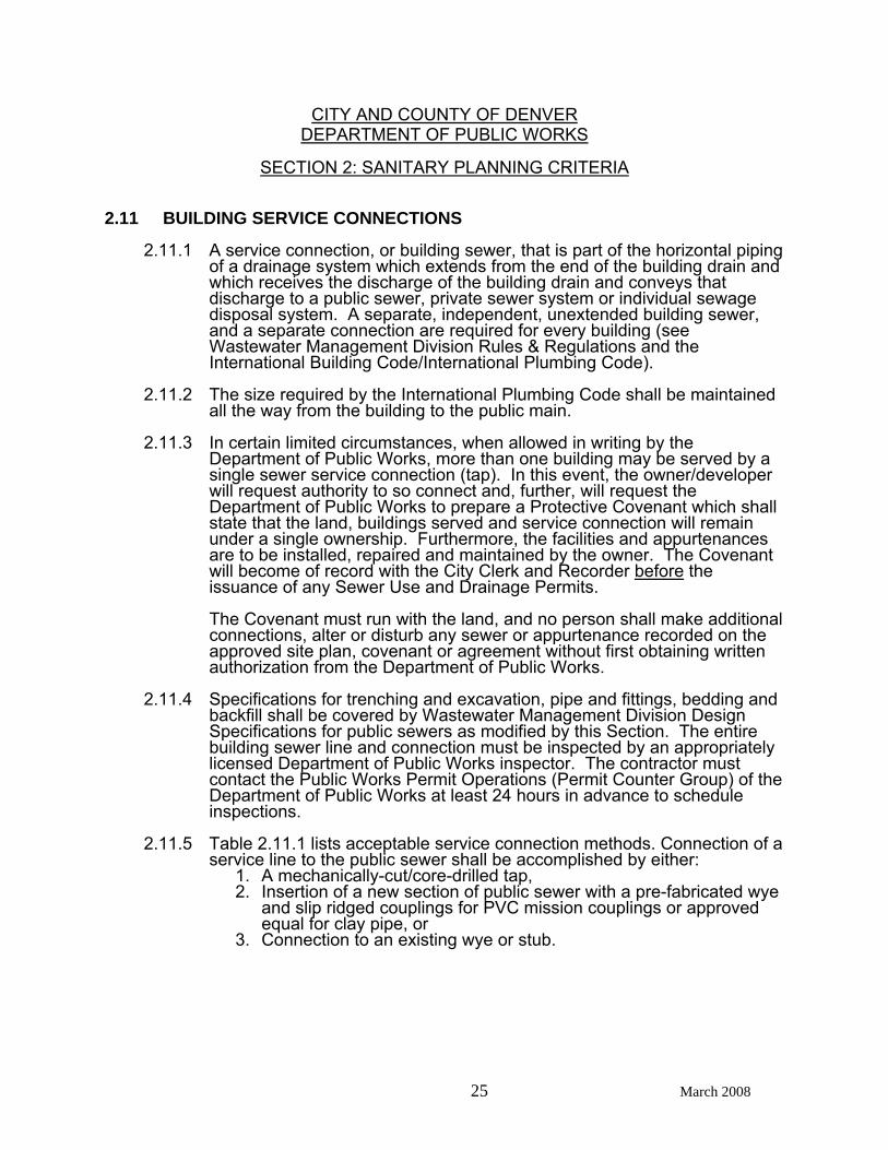
2.11 BUILDING SERVICE CONNECTIONS 2.11.1 A service connection, or building sewer, that is part of the horizontal piping
of a drainage system which extends from the end of the building drain and which receives the discharge of the building drain and conveys that discharge to a public sewer, private sewer system or individual sewage disposal system. A separate, independent, unextended building sewer, and a separate connection are required for every building (see Wastewater Management Division Rules & Regulations and the International Building Code/International Plumbing Code).
2.11.2 The size required by the International Plumbing Code shall be maintained
all the way from the building to the public main. 2.11.3 In certain limited circumstances, when allowed in writing by the
Department of Public Works, more than one building may be served by a single sewer service connection (tap). In this event, the owner/developer will request authority to so connect and, further, will request the Department of Public Works to prepare a Protective Covenant which shall state that the land, buildings served and service connection will remain under a single ownership. Furthermore, the facilities and appurtenances are to be installed, repaired and maintained by the owner. The Covenant will become of record with the City Clerk and Recorder before the issuance of any Sewer Use and Drainage Permits.
The Covenant must run with the land, and no person shall make additional
connections, alter or disturb any sewer or appurtenance recorded on the approved site plan, covenant or agreement without first obtaining written authorization from the Department of Public Works.
2.11.4 Specifications for trenching and excavation, pipe and fittings, bedding and
backfill shall be covered by Wastewater Management Division Design Specifications for public sewers as modified by this Section. The entire building sewer line and connection must be inspected by an appropriately licensed Department of Public Works inspector. The contractor must contact the Public Works Permit Operations (Permit Counter Group) of the Department of Public Works at least 24 hours in advance to schedule inspections.
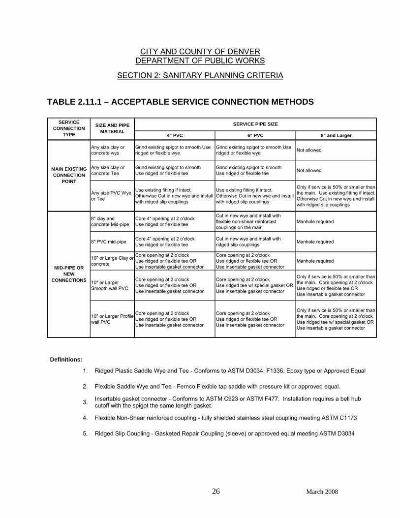
2.11.5 Table 2.11.1 lists acceptable service connection methods. Connection of a
service line to the public sewer shall be accomplished by either: 1. A mechanically-cut/core-drilled tap, 2. Insertion of a new section of public sewer with a pre-fabricated wye
and slip ridged couplings for PVC mission couplings or approved equal for clay pipe, or
3. Connection to an existing wye or stub.
CITY AND COUNTY OF DENVER DEPARTMENT OF PUBLIC WORKS
SECTION 2: SANITARY PLANNING CRITERIA
26 March 2008
TABLE 2.11.1 – ACCEPTABLE SERVICE CONNECTION METHODS
4" PVC 6" PVC 8" and Larger
Any size clay or concrete wye
Grind existing spigot to smooth Use ridged or flexible wye
Grind existing spigot to smooth Use ridged or flexible wye Not allowed
Any size clay or concrete Tee
Grind existing spigot to smooth Use ridged or flexible tee
Grind existing spigot to smooth Use ridged or flexible tee Not allowed
Any size PVC Wye or Tee
Use existing fitting if intact.Otherwise Cut in new wye and install with ridged slip couplings
Use existing fitting if intact.Otherwise Cut in new wye and install with ridged slip couplings
Only if service is 50% or smaller than the main. Use existing fitting if intact.Otherwise Cut in new wye and install with ridged slip couplings
8" clay and concrete Mid-pipe
Core 4" opening at 2 o'clockUse ridged or flexible tee
Cut in new wye and install with flexible non-shear reinforced couplings on the main
Manhole required
8" PVC mid-pipe Core 4" opening at 2 o'clockUse ridged or flexible tee
Cut in new wye and install with ridged slip couplings Manhole required
10" or Large Clay or concrete
Core opening at 2 o'clockUse ridged or flexible tee ORUse insertable gasket connector
Core opening at 2 o'clockUse ridged or flexible tee ORUse insertable gasket connector
Manhole required
10" or Larger Smooth wall PVC
Core opening at 2 o'clockUse ridged or flexible tee ORUse insertable gasket connector
Core opening at 2 o'clockUse ridged tee w/ special gasket OR Use insertable gasket connector
Only if service is 50% or smaller than the main. Core opening at 2 o'clockUse ridged or flexible tee ORUse insertable gasket connector
10" or Larger Profile wall PVC
Core opening at 2 o'clockUse ridged or flexible tee ORUse insertable gasket connector
Core opening at 2 o'clockUse ridged or flexible tee ORUse insertable gasket connector
Only if service is 50% or smaller than the main. Core opening at 2 o'clockUse ridged tee w/ special gasket OR Use insertable gasket connector
SERVICE PIPE SIZESIZE AND PIPE MATERIAL
MAIN EXISTING CONNECTION
POINT
MID-PIPE OR NEW
CONNECTIONS
SERVICE CONNECTION
TYPE
Definitions:
1. Ridged Plastic Saddle Wye and Tee - Conforms to ASTM D3034, F1336, Epoxy type or Approved Equal
2. Flexible Saddle Wye and Tee - Fernco Flexible tap saddle with pressure kit or approved equal.
3. Insertable gasket connector - Conforms to ASTM C923 or ASTM F477. Installation requires a bell hub cutoff with the spigot the same length gasket.
4. Flexible Non-Shear reinforced coupling - fully shielded stainless steel coupling meeting ASTM C1173
5. Ridged Slip Coupling - Gasketed Repair Coupling (sleeve) or approved equal meeting ASTM D3034
CITY AND COUNTY OF DENVER DEPARTMENT OF PUBLIC WORKS
SECTION 2: SANITARY PLANNING CRITERIA
27 March 2008
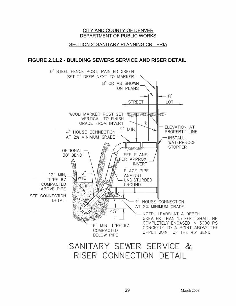
The separating distance between the building sewer and any parallel foundations or property boundaries must be at least equal to the depth of the building sewer (see the International Plumbing Code). The invert of each building sewer (tap) shall be placed at or above the springline of the public sewer at an angle of approximately 45 degrees with the springline unless otherwise determined by the Department of Public Works inspector in charge. See Figure 2.11.1 and Section 3.08.3.
2.11.6 Building sewer cleanouts shall be installed at intervals not to exceed 100
feet and/or for each aggregate change in direction exceeding 135 degrees. Each cleanout must be inspected and approved by a Department of Public Works inspector. Cleanouts must be the same size as the service size. Manholes must be installed in accordance with Chapter 3 – Design of Public Sewers on any building sewer greater than 6 inches in diameter (i.e. no cleanouts allowed).
2.11.7 Two-way cleanouts are required within 2 feet to 5 feet outside of a building
(or at other location as approved by the Wastewater Management Division inspector) on sewer service lines (see Figure 2.11.1).
2.11.8 Building sewer size and slope shall be determined on the basis of the total
number of fixture units drained by such sewer, or the hydraulic capacity of the building sewer. In no case shall a building sewer be less than four (4) inches in diameter (inside diameter). Minimum slope allowable for a 4 inch building sewer is 2% (1/4 inch per foot).
2.11.9 When sewer service cannot be obtained under traditional gravity
conditions the owner may request Department of Public Works to approve the use of an ejector system and force main. Force mains less than 4 inches in diameter must connect to the public sanitary sewer through a standard tee or wye. The force main must connect to the tee or wye in a manner to prevent leakage and to prevent sewage from entering the force main when the main line sewer is flowing full. After the connection is inspected the connection must be concrete encased to prevent separation due to thrust. The connection must be specifically detailed and Department of Public Works must approve the detail. Force mains need to be installed at a minimum depth of 4.5 feet to prevent freezing. At any time the force main is less than 4.5 feet deep it must be protected against freezing. Force mains 4-inch in diameter and greater must be constructed in accordance with Section 3.19.12.

CITY AND COUNTY OF DENVER DEPARTMENT OF PUBLIC WORKS
SECTION 2: SANITARY PLANNING CRITERIA
28 March 2008
FIGURE 2.11.1 - BUILDING SEWERS SERVICE LINE CLEAN-OUT
CITY AND COUNTY OF DENVER DEPARTMENT OF PUBLIC WORKS
SECTION 2: SANITARY PLANNING CRITERIA
29 March 2008
FIGURE 2.11.2 - BUILDING SEWERS SERVICE AND RISER DETAIL
CITY AND COUNTY OF DENVER DEPARTMENT OF PUBLIC WORKS
SECTION 2: SANITARY PLANNING CRITERIA
30 March 2008
2.12 SEWER ABANDONMENTS 2.12.1 Requests to abandon an existing (public or private) sewer line must be
submitted by the property owner(s), which are or could potentially be served by the facility to be abandoned, in writing to the Department of Public Works for approval. The request will provide a detailed site plan, along with justification for abandonment. Proof of property ownership must also be submitted.
The Department of Public Works will review requests and determine if it
can be granted. If permission to abandon can be given the Department of Public Works will issue a Sewer Abandonment Permit. The owner or his agent is then responsible to schedule an on-site inspection through the Department of Public Works Permit Operations (Permit Counter Group) at least 24 hours in advance of the desired inspection time. All sewer work will be performed to meet Wastewater Management Division standards and the contractor must be licensed to work in the public right-of-way.
2.12.2 Manholes to be abandoned in place shall have all pipes entering or exiting
the structure plugged with lean concrete so they are watertight. Manhole tops or cone sections shall be removed to the first full barrel diameter section, and/or to a point not less than 24-inches below final grade. No sandbags are allowed to be used as permanent plugs. The structure shall then be backfilled and compacted in accordance with the Detail and Technical Specifications. Backfill material may be either: select backfill, clean suitable excavated material, or controlled low strength material. Manhole rings, covers, cone sections will be removed and returned to Wastewater Management Division unless they have been approved to be used elsewhere for sewer relocation.
2.12.3 Sewer lines to be abandoned in place shall be plugged with lean concrete
and standard manufactured plugs or caps at both upstream and downstream ends of the abandoned section. If the manholes are also abandoned in place, or if the structure is to be removed completely, all sewer lines shall be plugged upstream and downstream of the removed structure following removal. Sewer lines to be abandoned with an internal diameter of 24-inch or larger shall be filled with sand, pumped grout mixtures, or flowable fill in order to minimize future subsidence attributable to the potential collapse of the abandoned facility. Sewer lines with an internal diameter of 21-inches and smaller shall be plugged at entrance and exit ends with approved grout mixtures or concrete.
2.13 FOUNDATION DRAINS Foundation drains (underdrains) which are installed in order to drain groundwater
away from building foundations, lower the groundwater table elevation, or to otherwise collect groundwater for subsequent disposal/use SHALL NOT, unless specifically allowed by the Department of Public Works in writing, be located in the same trench as the sanitary sewer.
CITY AND COUNTY OF DENVER DEPARTMENT OF PUBLIC WORKS
SECTION 2: SANITARY PLANNING CRITERIA
31 March 2008
2.13.1 Should an underdrain system be allowed in the public right-of-way, a
detailed engineering report shall be submitted to the Department of Public Works for review and approval. The contents of this report shall include:
a. A brief description of the project and purpose, b. The proposed owner of the facilities, c. Engineering calculations yielding the expected seasonal average and
peak underdrain flow rates, d. The point of discharge to the storm sewer system (manhole or surface
water), and e. The report shall be signed and stamped by a Professional Engineer
currently registered in the State of Colorado. 2.13.2 Design plans for the underdrain system shall be submitted to the
Department of Public Works for review and approval. These plans shall, as a minimum, conform to the following:
a. Wastewater Management Division specifications and details for
trenching and bedding shall be used, b. That portion of the underdrain which is located within public Right-of-
Way must have a major encumbrance permit and shall be of solid wall pipe designed to flow under gravity conditions at no more than 50% of full depth at the expected peak flow rate,
c. All underdrain pipes shall be accessible for routine maintenance, d. The underdrain pipe shall be laid at an elevation higher than, and in a
trench separate from, the sanitary sewer or (at the sole discretion of the Department of Public Works) the underdrain may be laid at an elevation less than that of the sanitary sewer but must be enclosed in a separate bedding of crushed gravel which is completely wrapped with an appropriate "filter cloth" and the pipes separated (horizontally) by at least 5 feet of undisturbed native material,
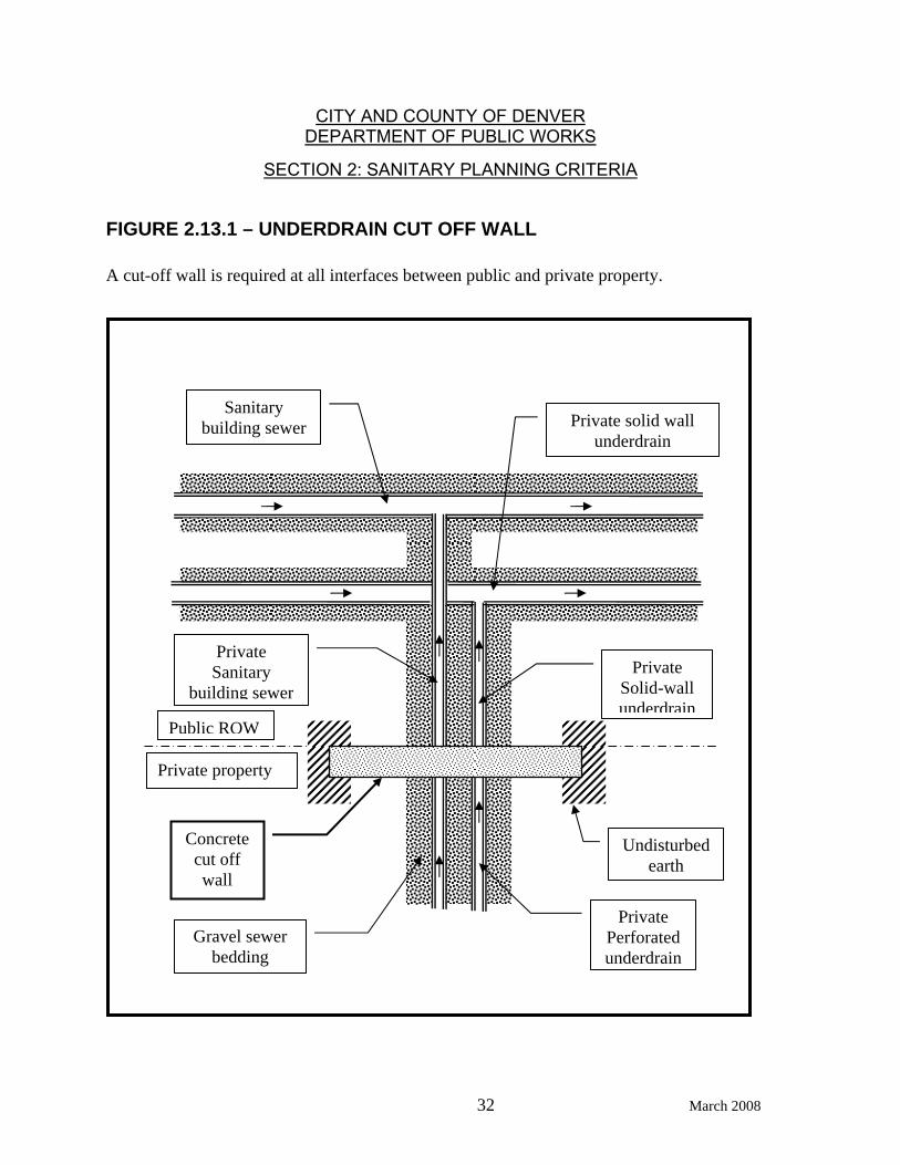
e. At any point where there may be gravel to gravel contact between the
underdrain trench and the sanitary sewer trench (e.g., on private property) a concrete cut off wall is required (e.g., at the property line) in order to assure that there is no continued flow of water in the sanitary trench, so that all water is "forced" into a perforated section of underdrain pipe as shown in Figure 2.13.1.
f. These requirements are a minimum and further conditions may be
imposed by the Department of Public Works in order to protect existing or proposed public facilities.
CITY AND COUNTY OF DENVER DEPARTMENT OF PUBLIC WORKS
SECTION 2: SANITARY PLANNING CRITERIA
32 March 2008
FIGURE 2.13.1 – UNDERDRAIN CUT OFF WALL A cut-off wall is required at all interfaces between public and private property.
Undisturbed earth
Concrete cut off wall
Private Perforated underdrain
Private Sanitary
building sewer
Sanitary building sewer
Gravel sewer bedding
Private solid wall underdrain
Private Solid-wall underdrain
Public ROW
Private property
CITY AND COUNTY OF DENVER DEPARTMENT OF PUBLIC WORKS
SECTION 3: DESIGN OF PUBLIC SEWERS
33 March 2008
3 DESIGN OF PUBLIC SEWERS
3.01 DEPTHS OF SEWERS The depth of a public sewer is the vertical distance from the ground surface over
the sewer to the invert of the sewer (Note: aerial sewers will not be allowed). 3.01.1 LINE DEPTHS: Except as required by other considerations, sewers
shall be designed with minimum depths of 9 feet. 3.01.2 BASEMENTS: The depth of a main sanitary sewer line must take into
account for any proposed basements to be served. 3.01.3 SERVICE CONNECTIONS: Minimum depths of public sewers with
relation to the building sewer, must include the additional depth required to accept the rise of the service connection.
3.01.4 SERVICE STUB-OUTS: If service stub-outs are to be provided, the
depth should be 4 feet below basement elevation. 3.02 DATUM All vertical survey control for sewer design shall be based upon established
U.S.G.S. (NAVD ‘88 datum) bench marks. 3.03 BENCHMARKS Each sewer project shall have its own vertical control circuit, and each bench
mark in the circuit shall be assigned the correct elevation in relation to all other bench marks in the circuit. Use City and County of Denver benchmarks where possible.
All bench marks in the circuit used shall be described on the title sheet under
"NOTICE TO CONTRACTORS", or at least two of the closest bench marks to the proposed work shall be shown on each sewer profile sheet and on each sewer plan sheet on which elevations are shown.
3.04 LOCATION AND ALIGNMENT The route selected for sewers shall be that which will provide satisfactory service
at minimum maintenance cost and which also provides the shortest distance to an existing public sewer main, unless influenced by other factors which shall be described during the preliminary design submittal phase. Hydraulic losses, due to any changes in direction of flow at manhole locations, will be calculated and compensated for, by invert drops across the manhole.
CITY AND COUNTY OF DENVER DEPARTMENT OF PUBLIC WORKS
SECTION 3: DESIGN OF PUBLIC SEWERS
34 March 2008
3.04.1 ALIGNMENT: Sewers shall be laid with straight alignment and uniform slope between manholes (see section 3.10).
Pipes of 24 inches or larger sizes shall not enter manholes so as to
create a change of direction of flow greater than 45 degrees. Any change of direction of flow for pipes greater than, or equal to, 42 inches will require a Type B or Type P manhole (see Section 3.09.3 and Wastewater Management Division Standard Details).
Whenever feasible, sewers shall be located in a zone between the
roadway centerline, or center of Right-of-Way, and 5 feet south or west of the centerline.
Potential interference with existing or proposed substructures shall be
considered during the design phase so as to maintain the maximum practicable distance between sewer lines and parallel structures or utilities.
Sewer lines shall not be located in other utility easements unless
specifically cleared beforehand (by written agreement) with the occupying utility AND the easement fully assigned to the City.
A lateral distance of 10 feet should be maintained between sewer lines
and other utilities, particularly gas and water lines. 3.04.2 RELATION TO WATER MAINS: Where sewer lines cross water mains
or where they come within 10 horizontal feet of each other, the sewer pipe shall be a minimum of 18 inches clear distance vertically below the water main. If this clear distance is not feasible, the pipe section must be designed and constructed so as to protect the water main.
Examples of such protection are: a. Concrete or vitrified clay sewer pipe shall be placed within a
reinforced concrete encasement. Encasement shall be at least 6 inches thick and extend a distance of 10 feet either side of the water main crossing point.
b. PVC pipe of the same diameter centered over the water main so
that joints are at least 10 feet on either side of the water main crossing shall be allowed. Suitable adaptors and encasement at transition points shall be required.
c. In all cases, installation of backfill shall preclude undue settling
and/or failure of the higher pipe.

CITY AND COUNTY OF DENVER DEPARTMENT OF PUBLIC WORKS
SECTION 3: DESIGN OF PUBLIC SEWERS
35 March 2008
3.04.3 EASEMENTS: a. Easement width (W) for single facility occupancy shall be calculated
using the formula: W = Bc + (2)*(H) + 3, where Bc = outside horizontal span of the pipe in feet, and H = depth from final surface elevation to the top of the pipe in feet. The required width given by the above formula shall be rounded to the
next highest 5 foot increment and the minimum easement width shall be 20 feet.
b. Easement width (Wn ) for multiple facilities (n>1) occupancy shall be
calculated using the formula:
3))()()(*)5.0((2
~~)1(11+++++= ∑
=−
n
nntonnCCn DHHBBW
n
where
Bc1 = outside horizontal span of pipe(1) in feet
and
Bcn = outside horizontal span of pipe(n) in feet
and 1H = depth from final surface elevation to the top of pipe (1) in
feet and Hn = depth from final surface elevation to the top of pipe (n) in
feet and D n to n( )~ ~−1 = distance between center of pipe(n-1) to center of
pipe(n) in feet. The required width given by the above formula shall be rounded to the
next highest 5 foot increment and the minimum easement width shall be 30 feet for two pipes. Contact Wastewater Management Division Right- of-Way Engineer for minimum widths involving more than two pipes (n>2).
3.04.4 RELATION TO WATERWAYS: Sanitary sewer lines may not be
located within any designated or proposed floodway. Sanitary sewer manholes may not be located within the limits of a detention pond.
3.04.5 CROSSING UTILITIES: Potholing of existing utilities is required as part
of the design to positively identify critical conflicts.

CITY AND COUNTY OF DENVER DEPARTMENT OF PUBLIC WORKS
SECTION 3: DESIGN OF PUBLIC SEWERS
36 March 2008
3.05 MULTIPLE PIPES IN A SINGLE TRENCH Pipes shall not be installed one over the other in the same trench. In situations involving unusual physical constraints which require pipes to be
installed in close lateral proximity shall be installed as follows: The deeper pipe shall be installed with standard trench method then backfilled to
an elevation at least 1 foot higher than the top of the proposed higher pipe. The higher pipe shall then be installed using standard trench method, backfilled to the level of the backfill of the first trench, then final common backfill completed to the original or designed ground surface elevation.
For further information concerning detailed pipeline installations see the Concrete
Pipe Handbook by the American Concrete Pipe Association. 3.06 HYDRAULIC DESIGN 3.06.1 PIPE SIZE: The size of pipe to be constructed as indicated on the plans
will represent the inside or nominal diameter of the pipe or sewer. No public sewer shall be less than 8 inches in diameter. Privately owned on-site sewers may be 6 inches in diameter (refer to section 2.10).
3.06.2 CAPACITY: Pipe size requirements shall be computed by using
Manning's formula. The coefficient of roughness, "n", shall be 0.013 for use in Manning's equation for the computation of pipe capacity for all pipe material types.
3.06.3 DEPTH OF FLOW: All sewers shall be designed to flow at a maximum
depth of 0.80 of pipe inside diameter at peak discharge (Qp). In all cases, a depth-variable friction factor shall be used such that the partial flow rate at 80% depth is approximately 86% of the sewer's full flow capacity (see Figure 2.07.1).
3.07 SLOPE OF SEWERS 3.07.1 MINIMUM SLOPES: The slope between manholes shall be uniform. To
prevent deposition of solids, all sewers should be so designed and constructed as to transport average sewage flow at mean velocities of 2.0 feet per second or greater. Where such constraints on the slope would not be practical as determined by the Wastewater Management Division, sewers must be installed such that the velocity of the sewage is at least 2.0 feet per second when the sewer is flowing full. The minimum slopes are presented in Table 3.07.
Whenever possible, sewers that are designed to carry an average
design flow of less than 0.10 cfs shall not be installed at a slope of less than 0.6%.
CITY AND COUNTY OF DENVER DEPARTMENT OF PUBLIC WORKS
SECTION 3: DESIGN OF PUBLIC SEWERS
37 March 2008
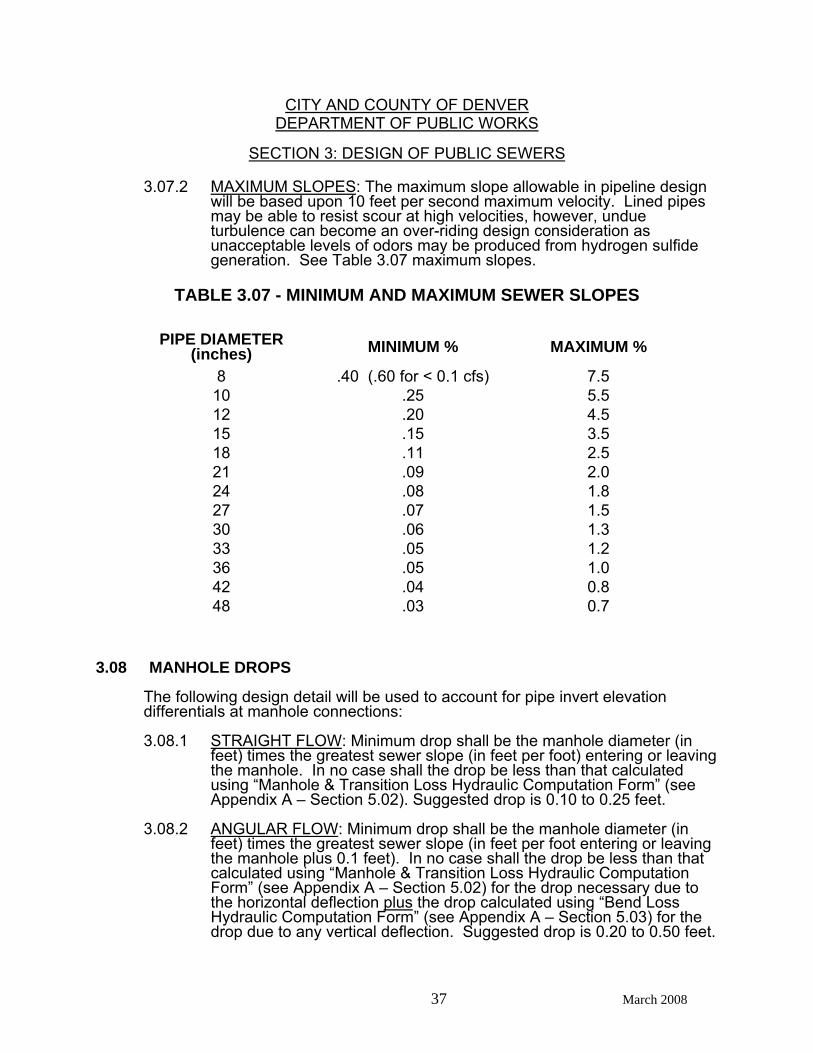
3.07.2 MAXIMUM SLOPES: The maximum slope allowable in pipeline design will be based upon 10 feet per second maximum velocity. Lined pipes may be able to resist scour at high velocities, however, undue turbulence can become an over-riding design consideration as unacceptable levels of odors may be produced from hydrogen sulfide generation. See Table 3.07 maximum slopes.
TABLE 3.07 - MINIMUM AND MAXIMUM SEWER SLOPES
PIPE DIAMETER (inches) MINIMUM % MAXIMUM %
8 .40 (.60 for < 0.1 cfs) 7.5 10 .25 5.5 12 .20 4.5 15 .15 3.5 18 .11 2.5 21 .09 2.0 24 .08 1.8 27 .07 1.5 30 .06 1.3 33 .05 1.2 36 .05 1.0 42 .04 0.8 48 .03 0.7
3.08 MANHOLE DROPS The following design detail will be used to account for pipe invert elevation
differentials at manhole connections: 3.08.1 STRAIGHT FLOW: Minimum drop shall be the manhole diameter (in
feet) times the greatest sewer slope (in feet per foot) entering or leaving the manhole. In no case shall the drop be less than that calculated using “Manhole & Transition Loss Hydraulic Computation Form” (see Appendix A – Section 5.02). Suggested drop is 0.10 to 0.25 feet.
3.08.2 ANGULAR FLOW: Minimum drop shall be the manhole diameter (in
feet) times the greatest sewer slope (in feet per foot entering or leaving the manhole plus 0.1 feet). In no case shall the drop be less than that calculated using “Manhole & Transition Loss Hydraulic Computation Form” (see Appendix A – Section 5.02) for the drop necessary due to the horizontal deflection plus the drop calculated using “Bend Loss Hydraulic Computation Form” (see Appendix A – Section 5.03) for the drop due to any vertical deflection. Suggested drop is 0.20 to 0.50 feet.
CITY AND COUNTY OF DENVER DEPARTMENT OF PUBLIC WORKS
SECTION 3: DESIGN OF PUBLIC SEWERS
38 March 2008
3.08.3 PIPE MATCHLINES: Laterals and other subordinate connections
(having a smaller diameter than the main line pipe) which are made at a manhole shall be aligned by matching crowns of the main-line pipe and the lateral pipe. (Also see Section 3.09.1).
Service connections must be made at a manhole whenever the service
line size is greater than 50% of the main line sewer size. All service connections to manholes shall conform to Wastewater Management Division Standards (also see Section 3.09.2). Service connections shall be aligned as denoted in Section 2.11.
3.08.4 DROP MANHOLES: The incorporation of outside drop manholes shall
be severely restricted by the designer to those locations where no other means of attaining slope or accommodating adequate flow velocity is feasible. Outside drop manholes shall conform to Wastewater Management Division Standard Details in configuration and size. Inside drop manholes are not allowed for either mainline sewers or service connections.
3.09 MANHOLES AND JUNCTION STRUCTURES, ETC The channel shall be as smooth and as regular as possible with no angles or
projections which could result in turbulent flow and the consequent deposition of solids. The following design standards shall be met for manholes:
3.09.1 MANHOLE BENCHES: The top of the manhole bench shall be at the
same level as the crown of the highest sewer pipe entering the manhole (except for the upper connection of outside drop structures).
The manhole benches shall not slope excessively (less than 2%) in any
direction. The benches shall be level and of an equal approximate length on either side of the main channel in order to provide a good working platform for sewer maintenance personnel.
3.09.2 SERVICE CONNECTIONS TO MANHOLES: Sanitary service lines
(building sewers) must be connected to city main-line manholes whenever the service line size is greater than 50% of the main line sewer size (see Section 3.08.3). Service lines of 6-inch diameter may connect without manholes at the discretion of the Department of Public Works.
3.09.3 STANDARD MANHOLES: Standard manholes are designed to fit
sewers from 8 to 48 inches in diameter. If the manhole deviates from standard plans, the word "Special" shall be included in the manhole designation.
CITY AND COUNTY OF DENVER DEPARTMENT OF PUBLIC WORKS
SECTION 3: DESIGN OF PUBLIC SEWERS
39 March 2008
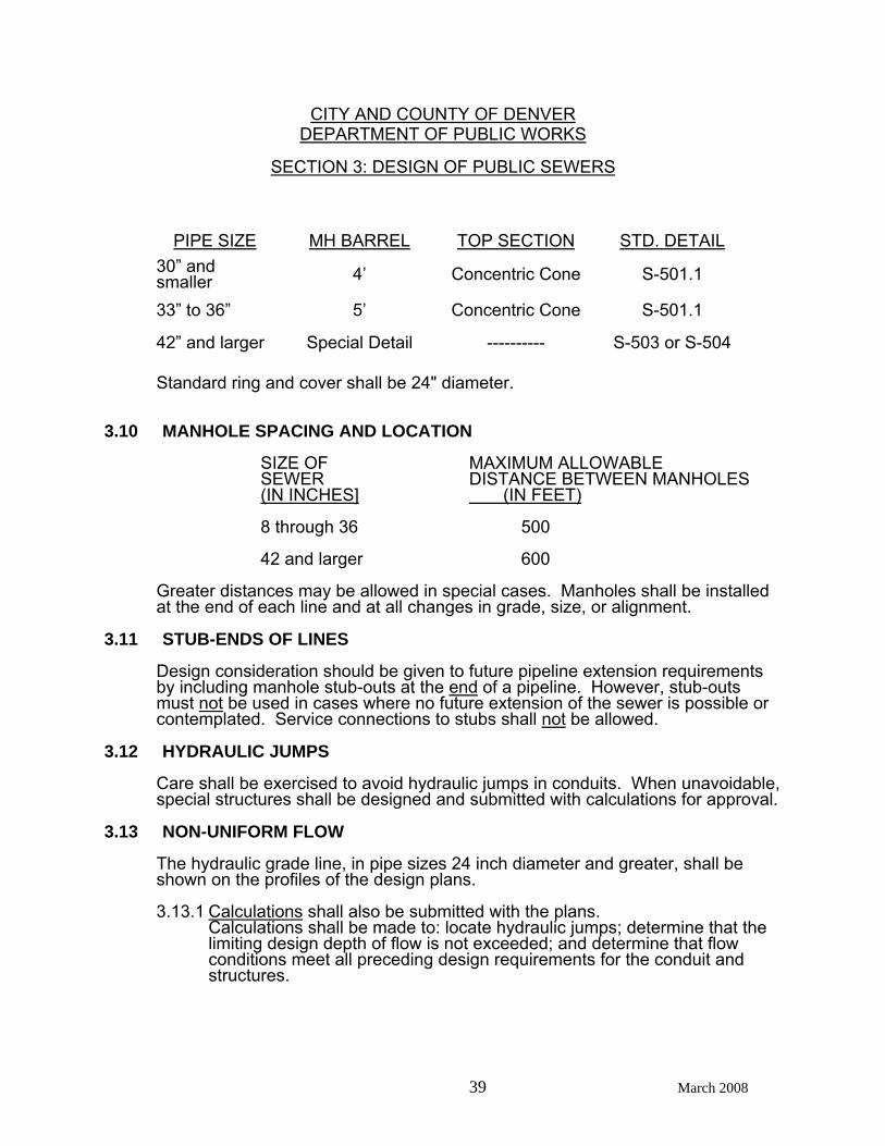
PIPE SIZE MH BARREL TOP SECTION STD. DETAIL 30” and smaller 4’ Concentric Cone S-501.1
33” to 36” 5’ Concentric Cone S-501.1
42” and larger Special Detail ---------- S-503 or S-504 Standard ring and cover shall be 24" diameter. 3.10 MANHOLE SPACING AND LOCATION SIZE OF MAXIMUM ALLOWABLE SEWER DISTANCE BETWEEN MANHOLES (IN INCHES] (IN FEET) 8 through 36 500 42 and larger 600 Greater distances may be allowed in special cases. Manholes shall be installed
at the end of each line and at all changes in grade, size, or alignment. 3.11 STUB-ENDS OF LINES Design consideration should be given to future pipeline extension requirements
by including manhole stub-outs at the end of a pipeline. However, stub-outs must not be used in cases where no future extension of the sewer is possible or contemplated. Service connections to stubs shall not be allowed.
3.12 HYDRAULIC JUMPS Care shall be exercised to avoid hydraulic jumps in conduits. When unavoidable,
special structures shall be designed and submitted with calculations for approval. 3.13 NON-UNIFORM FLOW The hydraulic grade line, in pipe sizes 24 inch diameter and greater, shall be
shown on the profiles of the design plans. 3.13.1 Calculations shall also be submitted with the plans.
Calculations shall be made to: locate hydraulic jumps; determine that the limiting design depth of flow is not exceeded; and determine that flow conditions meet all preceding design requirements for the conduit and structures.
CITY AND COUNTY OF DENVER DEPARTMENT OF PUBLIC WORKS
SECTION 3: DESIGN OF PUBLIC SEWERS
40 March 2008
3.14 INVERTED SIPHONS The design of Inverted Siphons (i.e. sag pipes) shall be avoided, however,
should one be needed, justification should be presented. When Inverted Siphon construction is necessary they shall have at least two
separate barrels, with a minimum pipe size of 8 inches, and shall be provided with necessary appurtenances for convenient flushing and maintenance; the inlet and outlet structures shall have adequate clearance for maintenance operations; and, sufficient head shall be provided and pipe sizes selected to insure velocities of at least 3.0 feet per second under average flow for both initial and future conditions. The inlet and outlet details shall be arranged so that the normal flow can be diverted to one barrel, and so that either barrel may be removed from service for cleaning or repair.
3.15 METER STATIONS Various types of sewage metering devices such as weirs, parshall flumes, and
Palmer-Bowlus flumes are listed in Chapter 7, Section P of the "WPCF Manual of Practice No. 9". Wastewater Management Division prefers the design and installation of the Palmer-Bowlus type metering device(s) due to ease of maintenance involved as compared to other devices.
3.16 STREAM & WATER CROSSINGS Design requirements shall be based upon results of site and soil/foundation
investigations and shall be shown on plans/drawings submittals. Pipelines shall be designed to overcome the effects of stream-bed scour action, erosive current effects, tangential loading (ice, water, wind) hydro-static uplift and from freezing. Protective structuring shall be provided in the design of pipelines lying above or below grade in rivers, streams or ponds, adequate to overcome adverse effects. Structuring may include such features as bridging, piles, caissons, or the employment of special materials, etc. Additionally, cut off walls must be installed at each end of the crossing.
3.17 STRUCTURAL REQUIREMENTS Pipes shall be designed taking into consideration dead load and live load, soil
characteristics and groundwater. Normally, polyvinyl chloride (PVC) is used in sanitary sewer lines unless excessive dead/live loads justify the use of other structurally adequate material accepted by Wastewater Management Division. Pressure lines (force mains, etc.) shall be designed for both internal pressure and dead/live loads to include bedding conditions.
3.18 DESIGN PARAMETERS Wastewater Management Division requires that structural analysis of pipe be
based upon the following considerations: a. A soil investigation will be performed as directed by Wastewater
Management Division to report on information such as type of soil(s), water levels, hammer (blow) penetration count, etc. Unit weights and
CITY AND COUNTY OF DENVER DEPARTMENT OF PUBLIC WORKS
SECTION 3: DESIGN OF PUBLIC SEWERS
41 March 2008
Atterberg Limits of typical soils on site can be determined by soil-lab testing. Class B Bedding constitutes the minimum acceptable class bedding to be employed. Bedding material shall conform to Wastewater Management Division’s “Detail and Technical Specifications.”
b. Large or extensive special structures will require additional soils
investigations compatible with the type of structure proposed. c. Standard Cooper's E-80 loading shall be used as live load at railroad
crossings. All pipe within railroad rights-of-way or railroad live load zone of influence, whichever is greater, shall be designed with Cooper's E-80 live load.
d. Pipes under street and highway rights-of-way shall be designed using
AASHTO H-20 live loads. e. Allowable deflection for various plastic and flexible pipes is stated in
Wastewater Management Division’s “Detail and Technical Specifications.” All design work will utilize the most currently applicable and most generally
recognized design standards, codes and practices for the type of work to be done. This will include, but not be limited to, the American Concrete Pipe Association, the Water Pollution Control Federation, American Association of State Highway and Transportation Officials, the American Concrete Institute, and the American Society of Civil Engineers.
3.18.1 PROTECTION OF CROSS TRENCH UTILITIES: Water lines, other
sewer lines, etc. which cross trenchline construction shall be denoted on design plans.
3.18.2 COMPACTION: Design Plans will be annotated to describe type of pipe
bedding material for use to include gradation specifications. 3.18.3 DEWATERING: Pipelines slated for construction in high-water table
areas should be adequately designed to include dewatering modes for well-point systems. Unstable soil areas may call for the placement of a well-point system. Incorporation of an underdrain system may be adopted to lower the water table and to provide a dry working area. However, no permanent underdrain system may be incorporated into the sanitary sewer bedding trench (see Section 2.13).
3.18.4 PIPE SUBSIDENCE OR MOVEMENT: In cases where sewer lines are
located in areas which induce or create undue pipeline subsidence or movement, special provisions for construction will be incorporated into the design. Under such unfavorable site conditions the following construction alternatives should be considered:
a. Reroute the pipeline to more favorable terrain or restrict entirely all
surcharge loads within 30 feet (or more) of the pipeline; or
b. Stabilize slopes by benching, terracing, use of retaining walls, placement of buttresses, etc.
CITY AND COUNTY OF DENVER DEPARTMENT OF PUBLIC WORKS
SECTION 3: DESIGN OF PUBLIC SEWERS
42 March 2008
c. Support the pipeline with pier and grade-beam system, consolidate fill before placement of the pipeline, increase class of pipe bedding, change type of pipe, and/or use flexible pipe/couplings.
3.19 DESIGN OF PUMPING STATION Wastewater pumping stations are to be situated above 100-year flood levels by
building a suitable structure, preferably located off the right-of-way of streets and alleys. Stations will be built for easy access into the pump-house. When wastewater must be pumped prior to grit removal, the wet well and the discharge piping shall be designed to prevent grit accumulation.
3.19.1 CONFIGURATION: The following items should be given consideration
in the design of wastewater pumping stations: a. Wet and drywells, including their super-structure, should be
completely separated. b. Provisions should be made to facilitate access to, and removal of,
pumps, motors, and valves for replacement/repair. Suitable and safe means of access should be provided to dry wells and
to wet wells containing either bar screens or other mechanical equipment for inspection or maintenance.
3.19.2 PUMP EQUIPMENT CHARACTERISTICS: a. DUPLICATE UNITS: Multiple pump units must be provided. Should
only two units be provided, equal capacity is required. Each pump shall be capable of handling flows in excess of the expected maximum flow. Where three or more pumps are provided, they should be designed to fit actual flow conditions and must be of such capacity that with any one pump out of service, the remaining pumps will have capacity to handle maximum wastewater flows.
Ejector - type and suction lift pumping stations will not be allowed
as public facilities. b. PROTECTION AGAINST CLOGGING: Pumps handling raw
wastewater should be preceded by readily accessible screens with clear openings not exceeding 2 inches, unless special devices such as comminutors are installed to protect the pumps from clogging or damage. “Comminutors” (a.k.a. grinders, macerators) are used to reduce the particle size of wastewater solids.
If the size of the installation warrants, a mechanically cleaned bar
screen with grinder is recommended. Where screens are located below ground, convenient facilities must be provided for handling screened materials. For the larger or deeper stations, duplicate units of proper capacity are preferred.
CITY AND COUNTY OF DENVER DEPARTMENT OF PUBLIC WORKS
SECTION 3: DESIGN OF PUBLIC SEWERS
43 March 2008
c. PUMP OPENINGS: Pumps should be capable of passing spheres of at least 3 inches in diameter. Pump suction and discharge openings shall be at least 4 inches in diameter.
d. PRIMING: The pump should be so placed that under normal
operating conditions it will operate under a net positive suction head (NPSH). The NPSH and suction lift requirements of the pumps shall be considered.
e. ELECTRICAL EQUIPMENT: Electrical equipment, located in
enclosed areas where gas may accumulate, shall comply with the National Board of Fire Underwriters' specifications for hazardous locations. Electrical equipment for pump motors shall contain elapsed time meters.
f. INTAKE: Each pump should have an individual intake. Wet well
design should be such as to avoid turbulence near the intake and cavitation in the pump.
g. DRY-WELL DEWATERING: A separate sump pump shall be
provided in dry wells to remove leakage or drainage with the discharge to the wet well above the overflow level of the wet well. Water ejectors connected to a potable water supply will not be approved. All floor and walkway surfaces should have an adequate slope to point of drainage.
h. PUMPING RATES: The pumps and controls of main pumping
stations, and especially pumping stations operated as part of treatment works or in developing areas, should be selected to operate at varying delivery rates.
3.19.3 PUMP CONTROLS: Liquid level controller activators should be so
located as not to be affected by flows entering the wet well or by the suction of the pumps. Float tubes in dry wells shall extend high enough to prevent overflow. Provisions should be made to provide automatic alternations of the pumps in use.
3.19.4 PUMP VALVES: Suitable (readily accessible) shutoff valves will be
located on suction and discharge lines of each pump. A check valve or pump control valve shall be placed on each discharge line, between the shutoff valve and the pump.
3.19.5 PUMP WET WELLS: a. DIVIDED WELLS: When continuous pump station operation is
required, division of the wet well into two sections may be constructed, with properly interconnected control gates, to facilitate repair and cleaning.
b. SIZE: The effective capacity of the wet well should provide a
holding period not to exceed 30 minutes for the design minimum
CITY AND COUNTY OF DENVER DEPARTMENT OF PUBLIC WORKS
SECTION 3: DESIGN OF PUBLIC SEWERS
44 March 2008
flow. Smaller wet wells may be considered when utilizing variable capacity pumping systems.
c. FLOOR SLOPE: The wet well floor should have a minimum slope
of 1 to 1 to the hopper bottom. The horizontal area of the hopper bottom should be no greater than necessary for proper installation and function of the pump inlet.
3.19.6 STATION VENTILATION: a. Adequate ventilation shall be provided for all pump stations to
mechanically ventilate the dry well. If screens or mechanical equipment requiring maintenance or inspection are located in the wet well, it shall be mechanically ventilated. There shall be no inter-connection between the wet well and dry well ventilating systems. In pits over 15 feet deep, multiple inlet and outlets are desirable. Dampers should not be used on exhaust or fresh air ducts and fine screens or other obstructions in the air ducts should be avoided to prevent clogging. Switches for operation of ventilation equipment should be marked and located conveniently. Consideration should be given to automatic controls where intermittent operation is practiced.
Where excessive moisture or low temperatures become a problem,
consideration should be given to installation of heating and/or dehumidification equipment.
b. WET WELLS: If mechanical wet well ventilation is required it should
be continuous and should provide at least 12 complete air changes per hour. For intermittent operation, at least 30 complete air changes per hour should be provided.
c. DRY WELLS: Ventilation may be either continuous or intermittent.
For continuous operation, at least 6 complete air changes per hour should be provided. For intermittent operation, at least 30 complete air changes per hour should be provided.
3.19.7 FLOW MEASUREMENT: At larger pumping stations, installation of
suitable devices for measuring, recording and totalizing sewage flow and power consumption should be a design consideration.
3.19.8 WATER SUPPLY: There shall be no direct connection between any
potable water supply and a sewage pumping station; otherwise, contamination of the potable water supply may result. Provision of a water supply for wash down should be planned.
3.19.9 POWER SUPPLY: Electric power supply will be tied-in from at least two
independent generating sources, or emergency power equipment should be provided. The need for automatic starting vs. manual starting of emergency power equipment shall be evaluated for each project. Emergency power generation units or portable pumping equipment on standby are considerations.
CITY AND COUNTY OF DENVER DEPARTMENT OF PUBLIC WORKS
SECTION 3: DESIGN OF PUBLIC SEWERS
45 March 2008
If the provision of an alternate power source is unfeasible, an overflow
should be provided at such an elevation as to prevent basement flooding or back water from affecting the operation. Where power failure would result in objectionable conditions because of resultant discharge or basement flooding, an emergency operation capability shall be provided. The need for the latter requirement will be determined for each proposed installation at the time plans are reviewed.
3.19.10 ALARM SYSTEMS: Alarm systems will be provided for all pumping
stations. The alarm shall become activated in cases of power failure, pump failure, or any other pump station malfunction. Pumping station alarms shall be telemetered. An audio-visual device may also be installed at the station so as to allow surveillance from the outside.
3.19.11 INSTRUCTION: Wastewater pumping stations and their operators
should be supplied with a complete set of equipment operational and maintenance instructions, including emergency procedures, maintenance procedures, tools and such spare parts as may be considered necessary.
All emergency power generation equipment should also be provided
with operation and maintenance instruction requiring routine starting and running of such units at full load.
3.19.12 FORCE MAINS (PUBLIC SYSTEM) - DESIGN: a. SIZE and NUMBER: The minimum allowable force main size is four
inches in diameter. Consideration shall be given to the use of multiple force mains to accommodate expected flows throughout the intended useful life of the pumping station as well as to ease maintenance operations.
b. VELOCITY: At the design pumping rate (initial and ultimate), the
velocity shall be at least 3 feet per second but not more than 5 feet per second.
c. AIR RELIEF VALVE: An automatic air relief valve shall be placed at
high points in the force main to prevent air locking. d. TERMINATION: Force mains shall transition into the gravity sewer
system at a manhole. The connection of the force main to the manhole shall be made by connecting the force main to a short section of gravity main stubbed out from the manhole. The gravity line shall be a minimum size of 8 inches and it shall be installed at a grade which will prevent wastewater from discharging back into the force main when the gravity system is flowing full.
CITY AND COUNTY OF DENVER DEPARTMENT OF PUBLIC WORKS
SECTION 3: DESIGN OF PUBLIC SEWERS
46 March 2008
3.19.13 PUMP CYCLING: Pump, wet well and force main configuration and capacity will be considered in order to reduce excessive pump cycling over the range of flow rates expected during the design life of the pumping station.
3.19.14 SPECIAL CONDITIONS: Pumping station designs which do not follow
the design criteria listed above will be evaluated on an individual basis. Special circumstance may warrant additional requirements.
3.20 OPERATIONS IN HEAVILY TRAVELED STREETS In certain heavily traveled streets and intersections, the usual and permitted
methods of construction operations may result in severe traffic congestion. In such cases, pipe jacking, tunneling, boring and casing, special shoring, etc., or limited operations may be required. In such instances, full coordination with the Traffic Engineering Division is required and the maximum allowable area limits of the construction operation as well as all traffic control and safety requirements shall be noted on the Plans or in the Specifications.
3.21 TYPES OF SEWER CONSTRUCTION AND LOADING CONDITIONS The classifications of underground construction conditions for determination of
loads on conduits fall into three (3) major categories:
Trench Conditions Embankment Conditions Tunnel Conditions (including jacking or boring)
The designer's attention is directed to WPCF "Manual of Practice No. 9" and
other technical engineering literature for a more detailed coverage of the above trench conditions and for various types of loading conditions and structural design requirements of sewer conduits.
3.22 BACKFILL AND SPECIAL COMPACTION The placement and consolidation of the backfill material and specification of
special backfill materials shall be in accordance with Wastewater Management Division Standard Construction Specifications and Standard Details.
Compaction or treatment controls shall be specified at the location on plans
where a pipeline will be affected by ground conditions as follows: a. In unconsolidated fills. b. Where the trench lies within the pressure zone of the footings of any
structure or building or within the pressure zone of any fill or steep slope.
c. High water tables. d. Other field conditions and locations which call for analysis of special
treatment control.
CITY AND COUNTY OF DENVER DEPARTMENT OF PUBLIC WORKS
SECTION 3: DESIGN OF PUBLIC SEWERS
47 March 2008
3.23 GROUNDWATER Whenever groundwater, or seepage prevails in a trench, the trench shall be
completely dewatered (so as to provide firm support below the bottom of the pipe or conduit) prior to pipe laying operations or the placement of the bedding material. Pumping, well points, or a subdrain system (either perforated pipe or gravel french drain) shall be employed to dewater site. Granular bedding material specified for Class B Bedding is not considered appropriate for trench drains and shall not be designed or used as such. An adequate free draining gravel material below the bedding material plus an appropriate filter media shall be designed for this type of subdrain system.
Where a subdrain system is designed to alleviate high groundwater conditions,
care and additional investigation should be exercised to assure that no subsidence of the adjacent ground will occur with consequent structural damage to surrounding buildings.
In the event that a subdrain system is constructed, and this system will continue
to function after the sewer has been installed, then provisions shall be made for positive outflow of the groundwater at an approved discharge point (river, gulch, storm sewer, etc.). No approval will be granted to discharge groundwater into the sanitary sewer system (see Section 2.13).
3.24 TUNNELING OF PIPELINES TUNNELING for a sewer line, as defined, encompasses one, or a combination
of, construction methods as listed below; these are: a. Utilization of a horizontal earth auger or boring machine. b. Jacking of a pre-formed steel or concrete outside pipe liner. The pipe
then is laid within or pulled through the liner. c. Sheeting, excavation, and bracing, as a shaft or tunnel is dug (mining). In order to specify the most appropriate method of tunneling during the project
design stage, the following factors should be given close consideration by the engineer before designation is made of the construction method(s) to be employed:
a. The results obtained from a geotechnical field investigation on-site, to
identify type of soils, moisture content, absence or presence of rock, shale, or high water tables, etc. to the depth of 2 feet below the pipeline.
b. Locations/lengths of tunneling, as may be necessitated, to install a
pipeline below railroad tracks or a busy street intersection where a "cut and cover" trench emplacement operation would not be appropriate or satisfactory due to traffic restrictions.
c. Pipeline structural or material requirements due to the location of a
railroad or highway to be included in the design. For example, Ductile
CITY AND COUNTY OF DENVER DEPARTMENT OF PUBLIC WORKS
SECTION 3: DESIGN OF PUBLIC SEWERS
48 March 2008
Iron Pipe extending 45 feet each side from the centerline of the railroad bed will be required for a pipeline lying below railroad tracks or to extend 10 feet outside the right-of-way, whichever is greater.
d. Utilization of an outside pipe liner, so as to assure that sufficiently
accurate pipe-slopes or elevations (as well as structural integrity) are maintained.
e. The presence of rock formations would signal that mining may be the
best construction method to incorporate into the design. f. Intensified loading on a jacked pipe should be anticipated as it may be
subjected to added loads should wet, cohesive soil deposits be encountered.
g. Placement of a pipe, by jacking through granular soils, may encounter
adverse frictional resistance dependent upon the soil density, moisture content, etc. in which case a lubricant may need to be employed.
3.25 HYDROGEN SULFIDE PRODUCTION Short and long term hydrogen sulfide production effects within any sanitary
sewer system should be addressed by the designer, particularly with respect to identifying and pinpointing those locations where high generation potential is likely. Pipelines must be able to fulfill a 50 year operational life as a minimum, therefore, sulfide deterioration effects should be assessed on this basis.
High sulfide generation potential locations may involve or be found in some of the
following settings: 1. Areas of high-turbulence in the stream-flow which generate
disagreeable and unacceptable levels of hydrogen sulfide gas. 2. Areas where sulfide levels equal or exceed 1 mg/liter and rates of flow
are low (without benefit of daily cleansing/oxidation) or where detention creates a loss of free oxygen levels below 50% of normal.
3. In areas where stream temperatures rise above the normal within the
sewer line environment due to highly thermal discharges.

CITY AND COUNTY OF DENVER DEPARTMENT OF PUBLIC WORKS
SECTION 3: DESIGN OF PUBLIC SEWERS
49 March 2008
Factors which bear upon the problems of pipeline malodorous gas and/or pipeline design life, and which act as remedial design measures are:
1. To use a pipe material which does not react to acid attack (e.g. PVC) or
vary the type of concrete pipe material in order to retard any corrosive action.
2. To treat flows with chlorine, lime, iron or zinc salts, hydrogen peroxide
or nitrate chemical compounds in sufficient quantities to eliminate dissolved sulfide based upon a periodic maintenance schedule for the length of pipeline affected.
3. To coat or sleeve the pipeline with a material which is non-reactive to
hydrogen sulfide (beware of fabrication faults however, which may accentuate sulfide concentrative deterioration). The limits of necessary protective lining for concrete pipe/structures shall be based upon the depth of flow for minimum discharge which limits sulfide generation and reaction.
4. To increase the size of pipe above the normal size, even though the
larger pipe is seemingly oversized for the design flow. The explanation for this design measure is that, for a given flow the width of the sewage surface (and thus surface area) increases with increasing pipe size leading to greater oxygen entrainment and less sulfide generation (however, care must be exercised in order to avoid detrimental velocity reduction). Also, the perimeter of the sewer (and thus "dry" surface area) increases with increasing pipe size leading to less wall penetration from a given amount of acid.
CITY AND COUNTY OF DENVER DEPARTMENT OF PUBLIC WORKS
SECTION 4: DESIGN DRAWINGS
50 March 2008
4 DESIGN DRAWINGS For examples of required submittals, see the CAD Standards Manual on the www.denvergov.org/ web site under: AGENCIES → PUBLIC WORKS → WASTEWATER MANAGEMENT DIVISION → WASTEWATER DESIGN ENGINEERING → WMD CAD STANDARDS. Or go directly to: www.denvergov.org/portals/526/documents/manual.pdf
4.01 FORMAT The following are minimum requirements for drawings to be submitted to the
Department of Public Works for review and approval. These requirements may be varied by the Department of Public Works in particular instances.
4.01.1 DRAWING SIZE: All drawings shall be 24-inches by 36-inches ('D'
size). 4.01.2 SCALE: The drawing scale shall be clearly indicated on all sheets and
shall be as follows (unless specifically varied by the Department of Public Works):
Easements/right-of-way - 1" = 20' or greater scale Horizontal or plan views - 1" = 50' Vertical or profile views - 1" = 5' 4.01.3 TITLE BLOCK: All drawings will have a Department of Public Works title
block and revision block on each design sheet or plan submitted in addition to the design firm's title block. The cover sheet will have a title/approval block in addition to the design firm's title block.
4.01.4 CERTIFICATION: Each sheet shall bear the Professional Engineer's
seal and signature of the responsible design engineer who shall be currently registered in the State of Colorado.
4.01.5 DRAFTING STANDARDS: The drafting standards to be used are as
shown on the above referenced Web site. 4.01.6 REVISIONS/CORRECTIONS: All changes made to a drawing since
either the previous review or as "as-built" changes shall be clearly noted both in the title block and on the drawing as a "flag" notation.
4.01.7 ORIENTATION: As viewer looks at the drawing(s) -
a. Lettering - All design drawings will orient so that the lettering reads left to right and top to bottom.
b. Drawing - On profile the pipe flow should be directed downhill to left
of drawings. 4.01.8 DETAIL DRAWINGS: Special detail drawings shall be prepared and
included as necessary or required.
CITY AND COUNTY OF DENVER DEPARTMENT OF PUBLIC WORKS
SECTION 4: DESIGN DRAWINGS
51 March 2008
4.01.9 MANHOLE COORDINATES: The drawing set must include a table of
manhole coordinates based upon the State Plane Coordinate System. These coordinates should be corrected to reflect "as-built" conditions.
4.01.10 SERVICE CONNECTIONS: If wyes or tees are to be installed for future
service connections, a table of service connections based upon the sewer pipe stationing and the direction of the wye or tee must be included and corrected to reflect "as-built" conditions.
4.02 COVER SHEET The following information shall be contained on the title page for the drawing set: a. Project Title (in large block letters) b. Location (Range, Township and Section) c. Vicinity map d. Drawing index (either pictorial or verbal) e. Title/Approval block (reference section 4.01.3), PE stamp and signature
(reference section 4.01.4) f. The name and address of the design firm and project owner(s) along
with the with the date of the design
g. Space for the Department of Public Works approval stamp (12-inches vertical by 4-inches horizontal) (see attached signature block format for Title Sheet).
h. Include and sign the Engineer’s Certification Block. With the final plan
submittal, the project design engineer must submit a stamped and signed letter of certification (certification block).
h. General notes as may be required or necessary 4.03 PLAN/PROFILE SHEETS Each sheet shall include the following information as applicable. 4.03.1 PLAN VIEW: a. Streets, alleys, lots, blocks, structures, utility lines, curbs, gutters,
fire-plugs, property lines, railways, range points, benchmarks, highways (within 100 feet of proposed construction) will be depicted in plan view and dimensioned per scale designated above. Similarly, all existing and proposed utility lines, sewer systems, storm drainage systems, highways, streets, and railway crossings located over, or under, proposed construction will be positioned and dimensioned in profile.
b. Natural or man-made features which may be displaced,
demolished, replaced, or otherwise disturbed by proposed
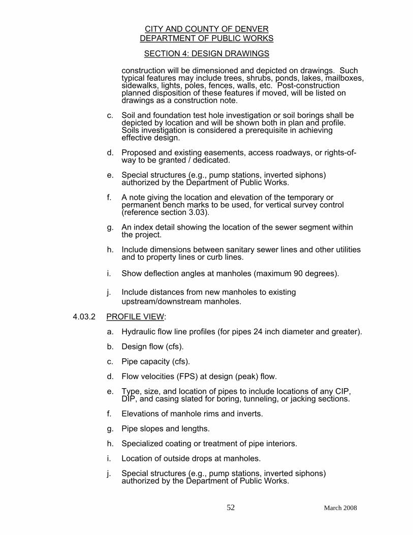
CITY AND COUNTY OF DENVER DEPARTMENT OF PUBLIC WORKS
SECTION 4: DESIGN DRAWINGS
52 March 2008
construction will be dimensioned and depicted on drawings. Such typical features may include trees, shrubs, ponds, lakes, mailboxes, sidewalks, lights, poles, fences, walls, etc. Post-construction planned disposition of these features if moved, will be listed on drawings as a construction note.
c. Soil and foundation test hole investigation or soil borings shall be
depicted by location and will be shown both in plan and profile. Soils investigation is considered a prerequisite in achieving effective design.
d. Proposed and existing easements, access roadways, or rights-of-
way to be granted / dedicated. e. Special structures (e.g., pump stations, inverted siphons)
authorized by the Department of Public Works. f. A note giving the location and elevation of the temporary or
permanent bench marks to be used, for vertical survey control (reference section 3.03).
g. An index detail showing the location of the sewer segment within
the project.
h. Include dimensions between sanitary sewer lines and other utilities and to property lines or curb lines.
i. Show deflection angles at manholes (maximum 90 degrees). j. Include distances from new manholes to existing
upstream/downstream manholes. 4.03.2 PROFILE VIEW: a. Hydraulic flow line profiles (for pipes 24 inch diameter and greater). b. Design flow (cfs). c. Pipe capacity (cfs). d. Flow velocities (FPS) at design (peak) flow. e. Type, size, and location of pipes to include locations of any CIP,
DIP, and casing slated for boring, tunneling, or jacking sections. f. Elevations of manhole rims and inverts. g. Pipe slopes and lengths. h. Specialized coating or treatment of pipe interiors. i. Location of outside drops at manholes. j. Special structures (e.g., pump stations, inverted siphons)
authorized by the Department of Public Works.
CITY AND COUNTY OF DENVER DEPARTMENT OF PUBLIC WORKS
SECTION 4: DESIGN DRAWINGS
53 March 2008
k. All crossing or close parallel utilities such as gas, water & electric. l. Any soil boring or test holes. m. Existing and proposed surface elevations. 4.04 AS BUILT DRAWINGS
“As built” drawings are to be submitted promptly to the Department of Public Works within 30 days of completion of the project. Submittal requirements for “As built” drawings to follow current standards as shown on the Denver website www.denvergov.org/ web site under: AGENCIES → PUBLIC WORKS → ENGINEERING DIVISION → DEVELOPMENT ENGINEERING SERVICES → DES ENGINEERING → STORM AND SANITARY SEWER REQUIREMENTS. Or go directly to: http://www.denvergov.org/DES_EngineeringSurvey/StormandSanitaryRequirements/tabid/38451
3/Default.aspx As built drawings are to be prepared from professionally surveyed information (i.e., not from the contractor).
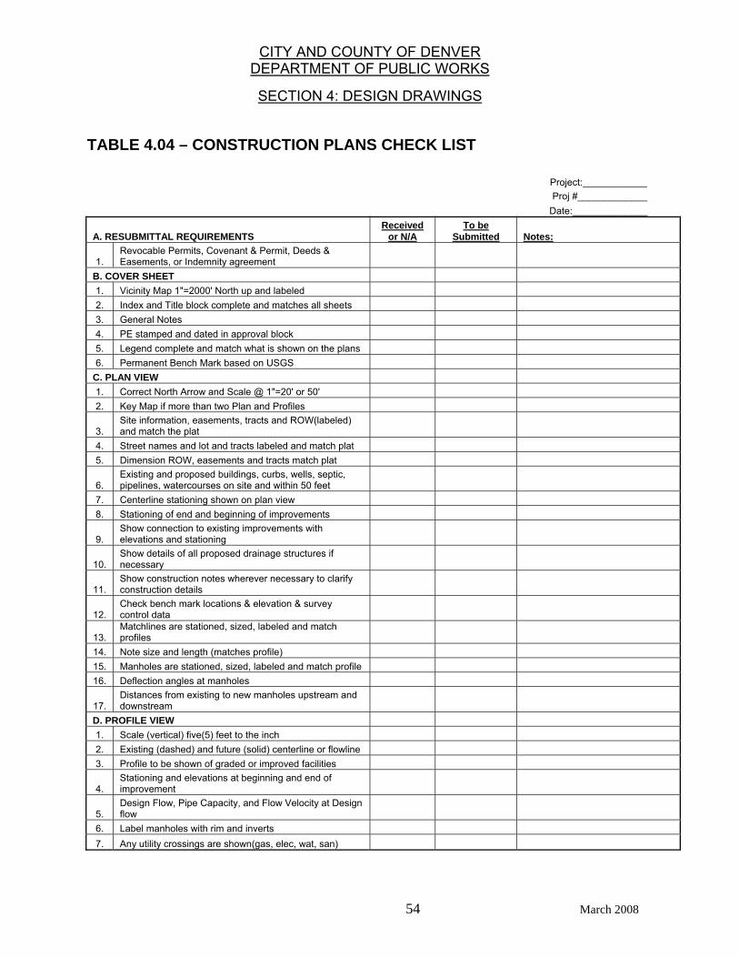
CITY AND COUNTY OF DENVER DEPARTMENT OF PUBLIC WORKS
SECTION 4: DESIGN DRAWINGS
54 March 2008
TABLE 4.04 – CONSTRUCTION PLANS CHECK LIST
Project:____________ Proj #_____________ Date:______________
A. RESUBMITTAL REQUIREMENTS Received
or N/A To be
Submitted Notes:
1. Revocable Permits, Covenant & Permit, Deeds & Easements, or Indemnity agreement
B. COVER SHEET 1. Vicinity Map 1"=2000' North up and labeled 2. Index and Title block complete and matches all sheets 3. General Notes 4. PE stamped and dated in approval block 5. Legend complete and match what is shown on the plans 6. Permanent Bench Mark based on USGS
C. PLAN VIEW 1. Correct North Arrow and Scale @ 1"=20' or 50' 2. Key Map if more than two Plan and Profiles
3. Site information, easements, tracts and ROW(labeled) and match the plat
4. Street names and lot and tracts labeled and match plat 5. Dimension ROW, easements and tracts match plat
6. Existing and proposed buildings, curbs, wells, septic, pipelines, watercourses on site and within 50 feet
7. Centerline stationing shown on plan view 8. Stationing of end and beginning of improvements
9. Show connection to existing improvements with elevations and stationing
10. Show details of all proposed drainage structures if necessary
11. Show construction notes wherever necessary to clarify construction details
12. Check bench mark locations & elevation & survey control data
13. Matchlines are stationed, sized, labeled and match profiles
14. Note size and length (matches profile) 15. Manholes are stationed, sized, labeled and match profile 16. Deflection angles at manholes
17. Distances from existing to new manholes upstream and downstream
D. PROFILE VIEW 1. Scale (vertical) five(5) feet to the inch 2. Existing (dashed) and future (solid) centerline or flowline 3. Profile to be shown of graded or improved facilities
4. Stationing and elevations at beginning and end of improvement
5. Design Flow, Pipe Capacity, and Flow Velocity at Design flow
6. Label manholes with rim and inverts 7. Any utility crossings are shown(gas, elec, wat, san)

CITY AND COUNTY OF DENVER DEPARTMENT OF PUBLIC WORKS
SECTION 4: DESIGN DRAWINGS
55 March 2008
FIGURE 4.04 - SIGNATURE BLOCK FORMAT FOR TITLE SHEET City and County of Denver
Department of Public Works Development Engineering Services
Checked for General Compliance with applicable Denver Criteria, Rules, Regulations and Standards.
APPROVED (if validly signed)
This approval becomes void if construction is not started
within one (1) year of the approval date.
____________________________ _____________ Development Engineering Services DATE _______________________________ (Note: Signature in Print)
APPROVED AS TO FORM. ENGINEERING CALCULATIONS, DRAWINGS AND DESIGN ADEQUACY ARE ACCEPTED BASED UPON THE PROJECT
ENGINEER’S ATTACHED SEAL OF REGISTRATION.
THIS APPROVAL IS FOR (PRIVATE)/(PUBLIC) (STORM)/(SANITARY) SEWER (RIGHT OF WAY
IMPROVEMENTS)
CALL THE UTILITY NOTIFICATION CENTER OF COLORADO AT 1-800-922-1987
TWO (2) BUSINESS DAYS IN ADVANCE BEFORE DIGGING, GRADING OR
EXCAVATION FOR MARKING OF MEMBER’S UNDERGROUND UTILITES
(Project Engineer’s Professional Engineer Seal, Signature and Date)
DES PROJECT NO.
PROJECT NAME:
DESIGNED BY DATE DATE ISSUED:
DRAWN BY DATE
CHECKED BY DATE SHEET___OF___SHEETS
DRAWING NO.
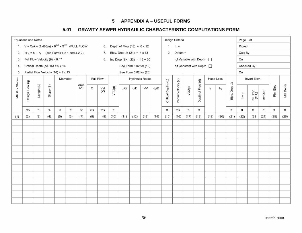
56 March 2008
5 APPENDIX A – USEFUL FORMS
5.01 GRAVITY SEWER HYDRAULIC CHARACTERISTIC COMPUTATIONS FORM
Equations and Notes Design Criteria Page of
1. V = Q/A = (1.486/n) x R2/3 x S1/2 (FULL FLOW) 6. Depth of Flow (18) = 6 x 12 1. n = Project
2. ΣHL = hi + hb (see Forms 4.2-1 and 4.2-2) 7. Elev. Drop (21) = 4 x 13 2. Datum = Calc By
3. Full Flow Velocity (9) = 8 / 7 8. Inv Drop (ΣHL, 23) = 19 + 20 n,f Variable with Depth On
4. Critical Depth (dc, 15) = 6 x 14 See Form 5.02 for (19) n,f Constant with Depth Checked By
5. Partial Flow Velocity (16) = 9 x 13 See Form 5.02 for (20) On
Full Flow Hydraulic Ratios Head Loss Invert Elev.
Des
ign
Flow
(q)
Leng
th (L
)
Slo
pe (S
)
Diameter
Area (A) Q Vel
(V)
V2 /(2
g)
Crit
ical
Dep
th (d
c)
Par
tial V
eloc
ity (v
)
v2 /(2g)
Dep
th o
f Flo
w (d
)
Ele
v. D
rop
Inv
In
Inv
Dro
p (Σ
HL)
Inv
Out
Rim
Ele
v
MH
Dep
th
MH
# o
r Sta
tion
cfs ft % in ft sf cfs fps ft
q/Q d/D v/V dc/D
ft fps ft ft
hi hb
ft ft ft ft ft ft
(1) (2) (3) (4) (5) (6) (7) (8) (9) (10) (11) (12) (13) (14) (15) (16) (17) (18) (19) (20) (21) (22) (23 (24) (25) (26)
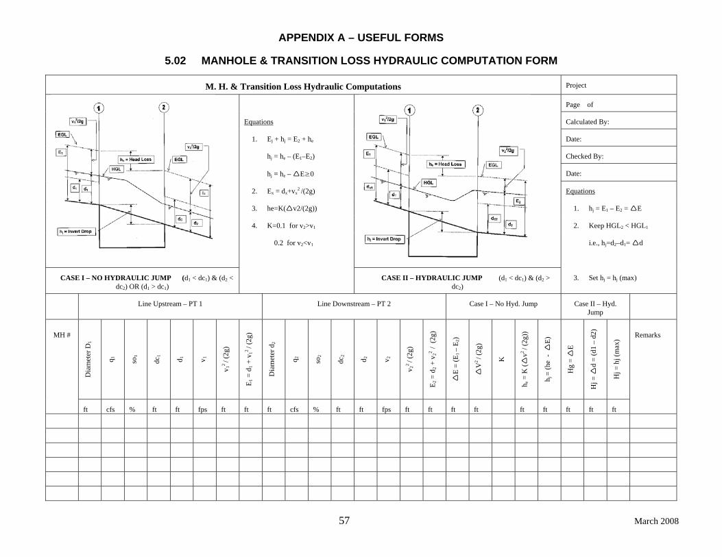
APPENDIX A – USEFUL FORMS
57 March 2008
5.02 MANHOLE & TRANSITION LOSS HYDRAULIC COMPUTATION FORM
M. H. & Transition Loss Hydraulic Computations Project
Page of
Equations Calculated By:
1. Ej + hj = E2 + he Date:
hj = he – (E1–E2) Checked By:
hj = he – E≥0 Date:
2. Ex = dx+vx2 /(2g) Equations
3. he=K( v2/(2g)) 1. hj = E1 – E2 = E
4. K=0.1 for v2>v1 2. Keep HGL2 < HGL1
0.2 for v2<v1
i.e., hj=d2–d1= d
CASE I – NO HYDRAULIC JUMP (d1 < dc1) & (d2 < dc2) OR (d1 > dc1)
CASE II – HYDRAULIC JUMP (d1 < dc1) & (d2 > dc2)
3. Set hj = hj (max)
Line Upstream – PT 1 Line Downstream – PT 2 Case I – No Hyd. Jump Case II – Hyd.
Jump
Dia
met
er D
1
q 1
so1
dc1
d 1
v 1
v 12 / (
2g)
E 1 =
d1 +
v12
/ (2g
)
Dia
met
er d
2
q 2
so2
dc2
d 2
v 2
v 22 / (
2g)
E 2 =
d2 +
v22
/ (2
g)
E =
(E1 –
E 2)
V2 / (
2g)
K
h e =
K (
v2 / (
2g))
h j =
(he
-
E)
Hg
= E
Hj =
d
= (d
1 –
d2)
Hj =
hj (
max
) MH #
ft cfs % ft ft fps ft ft ft cfs % ft ft fps ft ft ft ft ft ft ft ft ft
Remarks
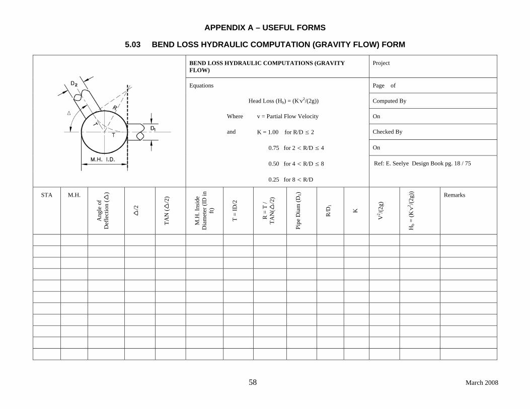
APPENDIX A – USEFUL FORMS
58 March 2008
5.03 BEND LOSS HYDRAULIC COMPUTATION (GRAVITY FLOW) FORM
BEND LOSS HYDRAULIC COMPUTATIONS (GRAVITY FLOW)
Project
Equations Page of
Head Loss (Hb) = (K.v2/(2g)) Computed By
Where v = Partial Flow Velocity On
and K = 1.00 for R/D ≤ 2 Checked By
0.75 for 2 < R/D ≤ 4 On
0.50 for 4 < R/D ≤ 8
0.25 for 8 < R/D
Ref: E. Seelye Design Book pg. 18 / 75
STA M.H.
Ang
le o
f D
efle
ctio
n (
)
/2
TAN
(/2
)
M.H
. Ins
ide
Dia
met
er (I
D in
ft)
T =
ID/2
R =
T /
TAN
(/2
)
Pipe
Dia
m (D
1)
R/D
1
K
V2 /(2
g)
Hb =
(K. v2 /(2
g)) Remarks
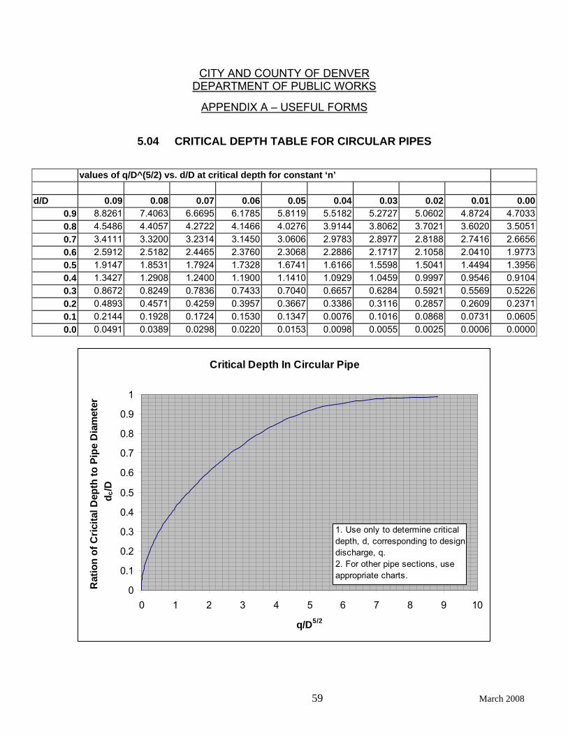
CITY AND COUNTY OF DENVER DEPARTMENT OF PUBLIC WORKS
APPENDIX A – USEFUL FORMS
59 March 2008
5.04 CRITICAL DEPTH TABLE FOR CIRCULAR PIPES
values of q/D^(5/2) vs. d/D at critical depth for constant ‘n’
d/D 0.09 0.08 0.07 0.06 0.05 0.04 0.03 0.02 0.01 0.000.9 8.8261 7.4063 6.6695 6.1785 5.8119 5.5182 5.2727 5.0602 4.8724 4.70330.8 4.5486 4.4057 4.2722 4.1466 4.0276 3.9144 3.8062 3.7021 3.6020 3.50510.7 3.4111 3.3200 3.2314 3.1450 3.0606 2.9783 2.8977 2.8188 2.7416 2.66560.6 2.5912 2.5182 2.4465 2.3760 2.3068 2.2886 2.1717 2.1058 2.0410 1.97730.5 1.9147 1.8531 1.7924 1.7328 1.6741 1.6166 1.5598 1.5041 1.4494 1.39560.4 1.3427 1.2908 1.2400 1.1900 1.1410 1.0929 1.0459 0.9997 0.9546 0.91040.3 0.8672 0.8249 0.7836 0.7433 0.7040 0.6657 0.6284 0.5921 0.5569 0.52260.2 0.4893 0.4571 0.4259 0.3957 0.3667 0.3386 0.3116 0.2857 0.2609 0.23710.1 0.2144 0.1928 0.1724 0.1530 0.1347 0.0076 0.1016 0.0868 0.0731 0.06050.0 0.0491 0.0389 0.0298 0.0220 0.0153 0.0098 0.0055 0.0025 0.0006 0.0000
Critical Depth In Circular Pipe
0
0.1
0.2
0.3
0.4
0.5
0.6
0.7
0.8
0.9
1
0 1 2 3 4 5 6 7 8 9 10
q/D5/2
Rat
ion
of C
ricita
l Dep
th to
Pip
e D
iam
eter
d c
/D
1. Use only to determine critical depth, d, corresponding to design discharge, q.2. For other pipe sections, use appropriate charts.
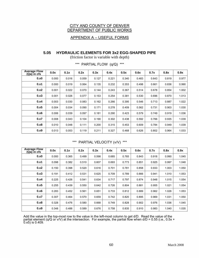
CITY AND COUNTY OF DENVER DEPARTMENT OF PUBLIC WORKS
APPENDIX A – USEFUL FORMS
60 March 2008
5.05 HYDRAULIC ELEMENTS FOR 3x2 EGG-SHAPED PIPE
(friction factor is variable with depth)
*** PARTIAL FLOW (q/Q) ***
Average Flow (Qa) in cfs 0.0x 0.1x 0.2x 0.3x 0.4x 0.5x 0.6x 0.7x 0.8x 0.9x
0.x0 0.000 0.016 0.059 0.127 0.221 0.340 0.483 0.643 0.819 0.977
0.x1 0.000 0.019 0.064 0.135 0.232 0.353 0.498 0.661 0.836 0.990
0.x2 0.001 0.022 0.070 0.144 0.243 0.367 0.514 0.678 0.854 1.002
0.x3 0.001 0.026 0.077 0.153 0.254 0.381 0.530 0.696 0.870 1.013
0.x4 0.003 0.030 0.083 0.162 0.266 0.395 0.546 0.713 0.887 1.022
0.x5 0.004 0.034 0.090 0.171 0.278 0.409 0.562 0.731 0.903 1.030
0.x6 0.006 0.039 0.097 0.181 0.290 0.423 0.579 0.749 0.919 1.036
0.x7 0.008 0.043 0.104 0.190 0.302 0.438 0.592 0.766 0.935 1.039
0.x8 0.010 0.048 0.111 0.200 0.315 0.453 0.609 0.784 0.949 1.039
0.x9 0.013 0.053 0.119 0.211 0.327 0.468 0.626 0.802 0.964 1.033
*** PARTIAL VELOCITY (v/V) ***
Average Flow (Qa) in cfs 0.0x 0.1x 0.2x 0.3x 0.4x 0.5x 0.6x 0.7x 0.8x 0.9x
0.x0 0.000 0.365 0.499 0.598 0.685 0.765 0.843 0.918 0.990 1.045
0.x1 0.098 0.382 0.510 0.607 0.693 0.773 0.851 0.925 0.997 1.048
0.x2 0.150 0.398 0.520 0.616 0.701 0.781 0.858 0.933 1.003 1.050
0.x3 0.191 0.412 0.531 0.625 0.709 0.789 0.866 0.941 1.010 1.053
0.x4 0.225 0.426 0.541 0.634 0.717 0.797 0.874 0.948 1.015 1.054
0.x5 0.255 0.439 0.550 0.642 0.726 0.804 0.881 0.955 1.021 1.054
0.x6 0.283 0.452 0.561 0.651 0.733 0.812 0.889 0.962 1.026 1.053
0.x7 0.307 0.464 0.570 0.659 0.742 0.820 0.895 0.969 1.031 1.050
0.x8 0.328 0.476 0.580 0.668 0.749 0.828 0.902 0.976 1.036 1.045
0.x9 0.348 0.488 0.589 0.676 0.758 0.835 0.910 0.983 1.040 1.035
Add the value in the top-most row to the value in the left-most column to get d/D. Read the value of the partial element (q/Q or v/V) at the intersection. For example, the partial flow when d/D = 0.55 (i.e., 0.5x + 0.x5) is 0.409.
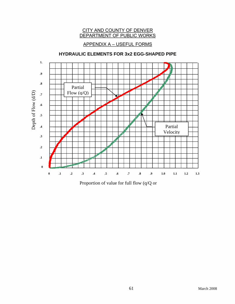
CITY AND COUNTY OF DENVER DEPARTMENT OF PUBLIC WORKS
APPENDIX A – USEFUL FORMS
61 March 2008
HYDRAULIC ELEMENTS FOR 3x2 EGG-SHAPED PIPE
0 .2 .3 .4 .5 .1 .6 .8 .9 1.0 1.1 .7 1.3 1.2
Proportion of value for full flow (q/Q or
0
1.
.9
.8
.7
.6
.5
.4
.3
.2
.1
Dep
th o
f Flo
w (d
/D)
Partial Velocity
Partial Flow (q/Q)

CITY AND COUNTY OF DENVER DEPARTMENT OF PUBLIC WORKS
APPENDIX A – USEFUL FORMS
62 March 2008
5.06 HYDRAULIC ELEMENTS FOR 1x1.575 HORIZONTAL ELLIPTICAL PIPE
(friction factor is variable with depth)
*** PARTIAL FLOW (q/Q) ***
Average Flow (Qa) in cfs 0.0x 0.1x 0.2x 0.3x 0.4x 0.5x 0.6x 0.7x 0.8x 0.9x
0.x0 0.000 0.015 0.064 0.147 0.261 0.401 0.562 0.736 0.906 1.032
0.x1 0.000 0.018 0.071 0.157 0.274 0.416 0.579 0.753 0.922 1.040
0.x2 0.001 0.022 0.078 0.168 0.287 0.432 0.596 0.771 0.937 1.048
0.x3 0.001 0.026 0.086 0.179 0.301 0.447 0.613 0.788 0.952 1.054
0.x4 0.002 0.030 0.093 0.189 0.314 0.463 0.631 0.806 0.965 1.058
0.x5 0.004 0.035 0.102 0.201 0.328 0.479 0.648 0.823 0.978 1.061
0.x6 0.005 0.040 0.110 0.212 0.342 0.496 0.665 0.840 0.990 1.062
0.x7 0.007 0.046 0.119 0.224 0.357 0.512 0.683 0.857 1.002 1.060
0.x8 0.010 0.051 0.128 0.236 0.371 0.528 0.701 0.874 1.013 1.055
0.x9 0.012 0.057 0.138 0.249 0.386 0.545 0.718 0.890 1.023 1.043
*** PARTIAL VELOCITY (v/V) ***
Average Flow (Qa) in cfs 0.0x 0.1x 0.2x 0.3x 0.4x 0.5x 0.6x 0.7x 0.8x 0.9x
0.x0 0.000 0.297 0.449 0.581 0.697 0.802 0.899 0.986 1.057 1.088
0.x1 0.073 0.314 0.463 0.593 0.708 0.812 0.908 0.994 1.062 1.088
0.x2 0.113 0.331 0.477 0.605 0.719 0.822 0.917 1.002 1.067 1.087
0.x3 0.144 0.347 0.491 0.617 0.730 0.832 0.926 1.009 1.072 1.086
0.x4 0.172 0.362 0.504 0.629 0.740 0.842 0.935 1.017 1.075 1.084
0.x5 0.197 0.377 0.517 0.641 0.751 0.851 0.944 1.025 1.079 1.081
0.x6 0.219 0.392 0.530 0.652 0.761 0.861 0.952 1.032 1.081 1.076
0.x7 0.241 0.406 0.543 0.664 0.772 0.871 0.961 1.038 1.083 1.069
0.x8 0.260 0.421 0.556 0.675 0.782 0.880 0.969 1.045 1.085 1.060
0.x9 0.279 0.435 0.568 0.686 0.792 0.890 0.978 1.051 1.087 1.045
Add the value in the top-most row to the value in the left-most column to get d/D. Read the value of the partial element (q/Q or v/V) at the intersection. For example, the partial flow when d/D = 0.55 (i.e., 0.5x + 0.x5) is 0.479.
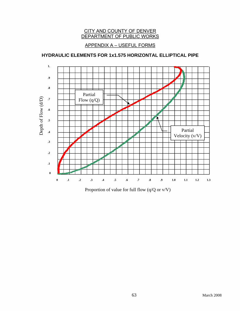
CITY AND COUNTY OF DENVER DEPARTMENT OF PUBLIC WORKS
APPENDIX A – USEFUL FORMS
63 March 2008
HYDRAULIC ELEMENTS FOR 1x1.575 HORIZONTAL ELLIPTICAL PIPE
0 .2 .3 .4 .5 .1 .6 .8 .9 1.0 1.1 .7 1.3 1.2
Proportion of value for full flow (q/Q or v/V)
0
1.
.9
.8
.7
.6
.5
.4
.3
.2
.1
Dep
th o
f Flo
w (d
/D) Partial
Flow (q/Q)
Partial Velocity (v/V)
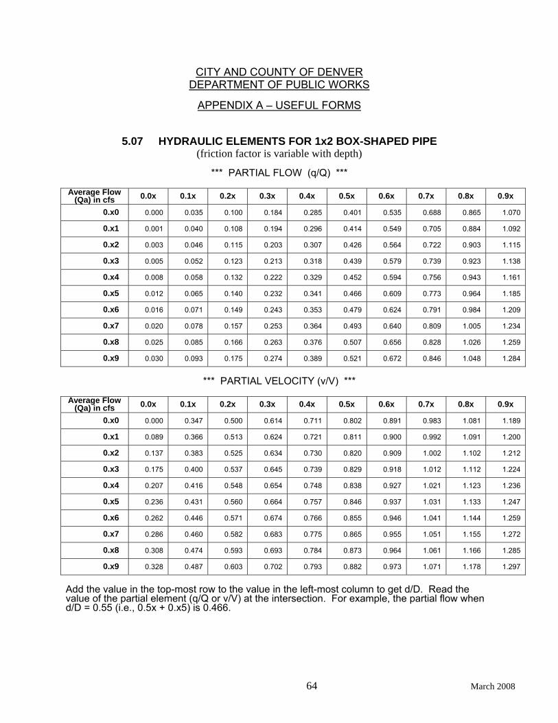
CITY AND COUNTY OF DENVER DEPARTMENT OF PUBLIC WORKS
APPENDIX A – USEFUL FORMS
64 March 2008
5.07 HYDRAULIC ELEMENTS FOR 1x2 BOX-SHAPED PIPE
(friction factor is variable with depth)
*** PARTIAL FLOW (q/Q) ***
Average Flow (Qa) in cfs 0.0x 0.1x 0.2x 0.3x 0.4x 0.5x 0.6x 0.7x 0.8x 0.9x
0.x0 0.000 0.035 0.100 0.184 0.285 0.401 0.535 0.688 0.865 1.070
0.x1 0.001 0.040 0.108 0.194 0.296 0.414 0.549 0.705 0.884 1.092
0.x2 0.003 0.046 0.115 0.203 0.307 0.426 0.564 0.722 0.903 1.115
0.x3 0.005 0.052 0.123 0.213 0.318 0.439 0.579 0.739 0.923 1.138
0.x4 0.008 0.058 0.132 0.222 0.329 0.452 0.594 0.756 0.943 1.161
0.x5 0.012 0.065 0.140 0.232 0.341 0.466 0.609 0.773 0.964 1.185
0.x6 0.016 0.071 0.149 0.243 0.353 0.479 0.624 0.791 0.984 1.209
0.x7 0.020 0.078 0.157 0.253 0.364 0.493 0.640 0.809 1.005 1.234
0.x8 0.025 0.085 0.166 0.263 0.376 0.507 0.656 0.828 1.026 1.259
0.x9 0.030 0.093 0.175 0.274 0.389 0.521 0.672 0.846 1.048 1.284
*** PARTIAL VELOCITY (v/V) ***
Average Flow
(Qa) in cfs 0.0x 0.1x 0.2x 0.3x 0.4x 0.5x 0.6x 0.7x 0.8x 0.9x
0.x0 0.000 0.347 0.500 0.614 0.711 0.802 0.891 0.983 1.081 1.189
0.x1 0.089 0.366 0.513 0.624 0.721 0.811 0.900 0.992 1.091 1.200
0.x2 0.137 0.383 0.525 0.634 0.730 0.820 0.909 1.002 1.102 1.212
0.x3 0.175 0.400 0.537 0.645 0.739 0.829 0.918 1.012 1.112 1.224
0.x4 0.207 0.416 0.548 0.654 0.748 0.838 0.927 1.021 1.123 1.236
0.x5 0.236 0.431 0.560 0.664 0.757 0.846 0.937 1.031 1.133 1.247
0.x6 0.262 0.446 0.571 0.674 0.766 0.855 0.946 1.041 1.144 1.259
0.x7 0.286 0.460 0.582 0.683 0.775 0.865 0.955 1.051 1.155 1.272
0.x8 0.308 0.474 0.593 0.693 0.784 0.873 0.964 1.061 1.166 1.285
0.x9 0.328 0.487 0.603 0.702 0.793 0.882 0.973 1.071 1.178 1.297
Add the value in the top-most row to the value in the left-most column to get d/D. Read the value of the partial element (q/Q or v/V) at the intersection. For example, the partial flow when d/D = 0.55 (i.e., 0.5x + 0.x5) is 0.466.
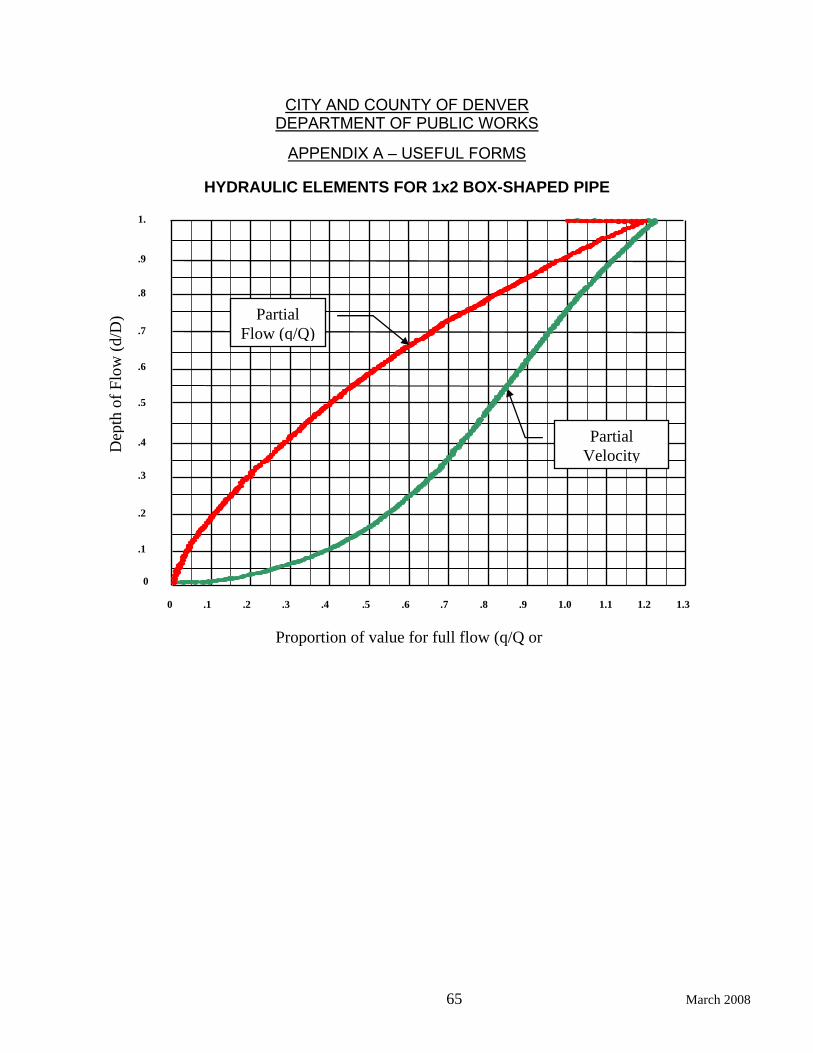
CITY AND COUNTY OF DENVER DEPARTMENT OF PUBLIC WORKS
APPENDIX A – USEFUL FORMS
65 March 2008
HYDRAULIC ELEMENTS FOR 1x2 BOX-SHAPED PIPE
0 .2 .3 .4 .5 .1 .6 .8 .9 1.0 1.1 .7 1.3 1.2
Proportion of value for full flow (q/Q or
0
1.
.9
.8
.7
.6
.5
.4
.3
.2
.1
Dep
th o
f Flo
w (d
/D)
Partial Velocity
Partial Flow (q/Q)

CITY AND COUNTY OF DENVER DEPARTMENT OF PUBLIC WORKS
APPENDIX B – LIFT STATION DESIGN
66 March 2008
6 APPENDIX B – LIFT STATION DESIGN
6.01 SANITARY SEWAGE PUMPING STATION / FORCE MAIN
Project No.: ___________________________________________________
Project Name: ___________________________________________________
___________________________________________________
Location: ___________________________________________________
___________________________________________________
___________________________________________________
R-T-S.Q: ___________________________________________________
Station Type, Configuration and Description: _____________________________
________________________________________________________
________________________________________________________
________________________________________________________
Sanitary or Design study reviewed/approved (Y/N)?_______ Date________
Flow Rates in cfs
YEAR PEAK MAX 1 HR MAX 6 HR AVERAGE MIN 1 HR
Initial
Design
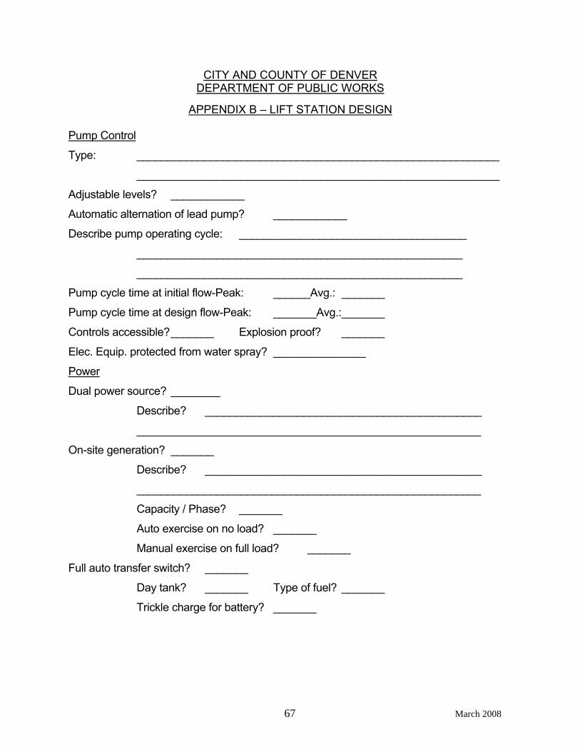
CITY AND COUNTY OF DENVER DEPARTMENT OF PUBLIC WORKS
APPENDIX B – LIFT STATION DESIGN
67 March 2008
Pump Control
Type: ___________________________________________________________
___________________________________________________________
Adjustable levels? ____________
Automatic alternation of lead pump? ____________
Describe pump operating cycle: _____________________________________
_____________________________________________________
_____________________________________________________
Pump cycle time at initial flow-Peak: ______Avg.: _______
Pump cycle time at design flow-Peak: _______Avg.: _______
Controls accessible? _______ Explosion proof? _______
Elec. Equip. protected from water spray? _______________
Power
Dual power source? ________
Describe? _____________________________________________
________________________________________________________
On-site generation? _______
Describe? _____________________________________________
________________________________________________________
Capacity / Phase? _______
Auto exercise on no load? _______
Manual exercise on full load? _______
Full auto transfer switch? _______
Day tank? _______ Type of fuel? _______
Trickle charge for battery? _______
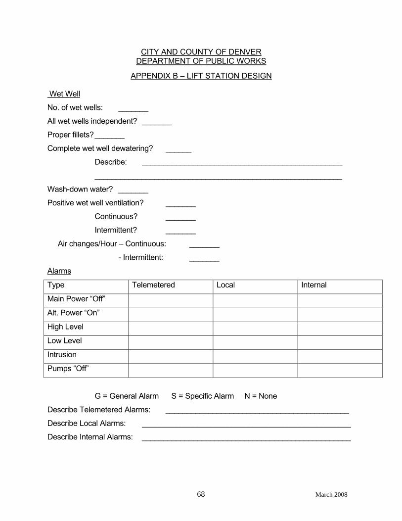
CITY AND COUNTY OF DENVER DEPARTMENT OF PUBLIC WORKS
APPENDIX B – LIFT STATION DESIGN
68 March 2008
Wet Well
No. of wet wells: _______
All wet wells independent? _______
Proper fillets? _______
Complete wet well dewatering? ______
Describe: _______________________________________________
__________________________________________________________
Wash-down water? _______
Positive wet well ventilation? _______
Continuous? _______
Intermittent? _______
Air changes/Hour – Continuous: _______
- Intermittent: _______
Alarms
Type Telemetered Local Internal
Main Power “Off”
Alt. Power “On”
High Level
Low Level
Intrusion
Pumps “Off”
G = General Alarm S = Specific Alarm N = None
Describe Telemetered Alarms: ___________________________________________
Describe Local Alarms: _________________________________________________
Describe Internal Alarms: _________________________________________________
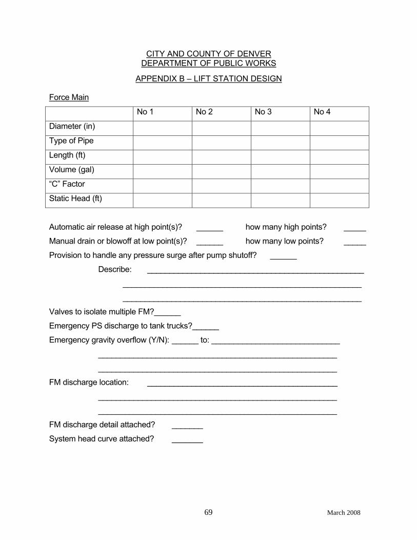
CITY AND COUNTY OF DENVER DEPARTMENT OF PUBLIC WORKS
APPENDIX B – LIFT STATION DESIGN
69 March 2008
Force Main
No 1 No 2 No 3 No 4
Diameter (in)
Type of Pipe
Length (ft)
Volume (gal)
“C” Factor
Static Head (ft)
Automatic air release at high point(s)? ______ how many high points? _____
Manual drain or blowoff at low point(s)? ______ how many low points? _____
Provision to handle any pressure surge after pump shutoff? ______
Describe: _________________________________________________
______________________________________________________
______________________________________________________
Valves to isolate multiple FM?______
Emergency PS discharge to tank trucks?______
Emergency gravity overflow (Y/N): ______ to: _____________________________
______________________________________________________
______________________________________________________
FM discharge location: ___________________________________________
______________________________________________________
______________________________________________________
FM discharge detail attached? _______
System head curve attached? _______
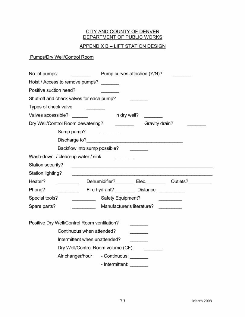
CITY AND COUNTY OF DENVER DEPARTMENT OF PUBLIC WORKS
APPENDIX B – LIFT STATION DESIGN
70 March 2008
Pumps/Dry Well/Control Room
No. of pumps: _______ Pump curves attached (Y/N)? _______
Hoist / Access to remove pumps? _______
Positive suction head? _______
Shut-off and check valves for each pump? _______
Types of check valve _______
Valves accessible? ______ in dry well? _______
Dry Well/Control Room dewatering? _______ Gravity drain? _______
Sump pump? _______
Discharge to? _____________________________________
Backflow into sump possible? _______
Wash-down / clean-up water / sink _______
Station security? ______________________________________________________
Station lighting? ______________________________________________________
Heater? ________ Dehumidifier?_______ Elec._______ Outlets?_________
Phone? ________ Fire hydrant? _______ Distance __________
Special tools? _________ Safety Equipment? _________
Spare parts? _________ Manufacturer’s literature? _________
Positive Dry Well/Control Room ventilation? _______
Continuous when attended? _______
Intermittent when unattended? _______
Dry Well/Control Room volume (CF): _______
Air changer/hour - Continuous: _______
- Intermittent: _______
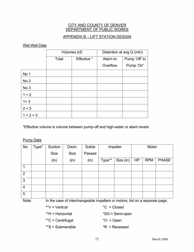
CITY AND COUNTY OF DENVER DEPARTMENT OF PUBLIC WORKS
APPENDIX B – LIFT STATION DESIGN
71 March 2008
Wet Well Data
Volumes (cf) Detention at avg Q (min)
Total Effective * Alarm to
Overflow
Pump ‘Off’ to
Pump ‘On”
No 1
No 2
No 3
1 + 2
1+ 3
2 + 3
1 + 2 + 3
*Effective volume is volume between pump-off and high-water or alarm levels
Pump Data
No Type* Suction
Size
Disch.
Size
Solids
Passed
Impeller Motor
(in) (in) (in) Type** Size (in) HP RPM PHASE
1
2
3
4
5
Note: In the case of interchangeable impellers or motors, list on a separate page.
**V = Vertical *C = Closed
**H = Horizontal *SO = Semi-open
**C = Centrifugal *O = Open
**S = Submersible *R = Recessed
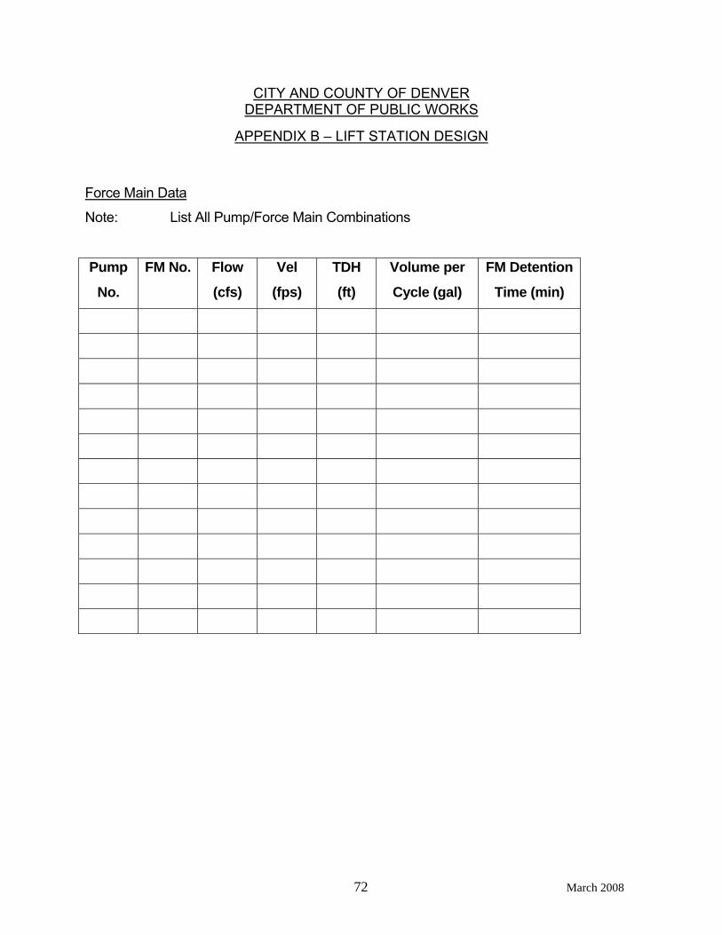
CITY AND COUNTY OF DENVER DEPARTMENT OF PUBLIC WORKS
APPENDIX B – LIFT STATION DESIGN
72 March 2008
Force Main Data
Note: List All Pump/Force Main Combinations
Pump
No.
FM No. Flow
(cfs)
Vel
(fps)
TDH
(ft)
Volume per
Cycle (gal)
FM Detention
Time (min)
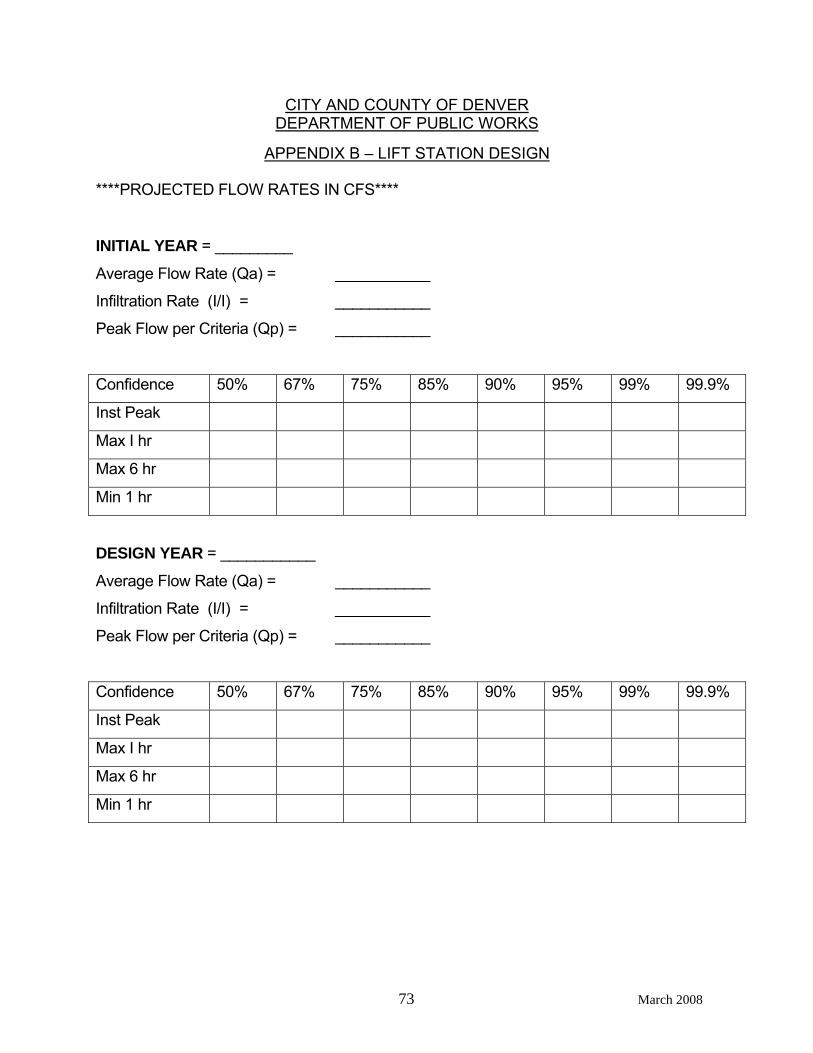
CITY AND COUNTY OF DENVER DEPARTMENT OF PUBLIC WORKS
APPENDIX B – LIFT STATION DESIGN
73 March 2008
****PROJECTED FLOW RATES IN CFS****
INITIAL YEAR = _________
Average Flow Rate (Qa) = ___________
Infiltration Rate (I/I) = ___________
Peak Flow per Criteria (Qp) = ___________
Confidence 50% 67% 75% 85% 90% 95% 99% 99.9%
Inst Peak
Max I hr
Max 6 hr
Min 1 hr
DESIGN YEAR = ___________
Average Flow Rate (Qa) = ___________
Infiltration Rate (I/I) = ___________
Peak Flow per Criteria (Qp) = ___________
Confidence 50% 67% 75% 85% 90% 95% 99% 99.9%
Inst Peak
Max I hr
Max 6 hr
Min 1 hr