sand-asphalt-sulfur pavement experimental project highway ... · sand-asphalt-sulfur pavement...
TRANSCRIPT
' I
SAND-ASPHALT-SULFUR PAVEMENT EXPERIMENTAL PROJECT
HIGHWAY U.S. 77, KENEDY COUNTY, TEXAS
A CONSTRUCTION REPORT
TEXAS TRANSPORTATION INSTITUTE
Texas A&M University College Station, Texas
•
• ..
- ~-----~-
SAND-ASPHALT-SULFUR PAVEMENT EXPERIMENTAL PROJECT
HIGHWAY U.S. 77, KENEDY COUNTY, TEXAS
A CONSTRUCTION REPORT
by
John 0. Izatt, P.E.
B. M. Gallaway, P.E.
D. Saylak, P.E.
April 1977
Texas Transportation Institute
College Station, Texas
TABLE OF CONTENTS
1.0 Introduction
1.1 1.2 1.3 1.4 1.5
Location and Scope , Construction Contract Participants • • • . • • • Sand-Asphalt-Sulfur Pavement The Need • • • . • • •
2.0 Construction Materials •
2.1 Sulfur ••••.••• 2. 2 Asphalt • • • . • 2.3 Mineral Aggregates
3.0 Contractor Equipment
3.1 General • • • . . • • • . 3.2 The Hot-Mix Plant • • • • •
3.2.1. Emission Control •• 3.2.2. Cold Aggregate Feed
Material
3. 2. 3. Electric Power • • • • . 3.2.4. Asphalt System •
3.3 The Sulfur System •••. 3.4 Special Heated Truck Bodies
3.4.1. Basic Features 3.4.2. Truck Mounting •••.. 3.4.3. Hoists ..•. 3.4.4. Trucks •.•• 3.4.5. Transportation
3.5 Paver - Modifications 3.5.1. Modification Kit • 3.5.2. Paver Characteristics
4.0 Construction Features
4.1 Sulfur Handling 4.1.1. Asphalt Contamination 4.1.2. Steam Boiler ••••• 4.1.3. Sulfur Tank Capacity • • ••. 4.1.4. Transport Handling~ •••.•. 4.1.5. Operating of Sulfur System ..••. 4.1.6. Sulfur Pump .••..••••• 4.1.7. Conclusion of Sulfur Operations
I
' .
Page
1
' • • 41
. . . . .
2 4 6 8 8
• • 10
• • 11 . . . . . 14
. . . . . . . . 15
• • • 19
• • . 19 . 19 . 20
20 . 22
• . 22 . • • 22
23 . 25
• • 2 7 • • • • • 2 7
• • • 2 7 • • • • 29
. • 30 • 30
. • 31
• 33
• • • • • 3 3 • • 33
34 • . 34
• • • 35 . . 36
. . . . . . 36 . • • 37
•
•
TABLE OF CONTENTS (CONTINUED)
4.2 Sulfur Balance .....• 4.3 Summary of Sulfur Handling 4.4 Subgrade - 811 Lime Treated Soil 4.5 Preparation and Placement of the Sand-Asphalt-Sulfur Mix •
4.5.1. Mixing . • . . .•. 4.5.2. Hauling •...... 4.5.3. Placing .•.•.. 4.5.4. Summary of Mixing and Placing 4. 5. 5. Joints • . • . • • . . . . • . 4.5.6. Patching . . . . . . . • . • . . • ••. 4.5.7. Smoothing the Pavement Surfaces ...• 4.5.8. Log of Field Construction - Sand-Asphalt-Sulfur Test Items •. 4.5.9. Weather .....•.•
4.6 Asphalt Concrete Pavement Test Items 4.6.1. Specifications .•....••. 4.6.2. Pavement Mixture Requirements 4.6.3. Materials ..... . 4.6.4. Characteristics ....••.. 4.6.5. Asphalt Concrete Mix Design 4.6.6. Quality Control 4.6.7. Construction ..
4.7 Evolved Gas Analysis .• 4.7.1. Equipment .... 4.7.2. Hydrogen Sulfide .•..
4.7.2.1. Relative Toxicity of H2S .•••. 4.7.2.2. Hydrogen Sulfide Test Results 4.7.2.3. Discussion of Results of H2S Evolved Gas Analysis
4.7.3. Sulfur Dioxide .••.•....•• 4.7.3.1. Relative Toxicity of S02 ..• 4. 7. 3. 2. Sulfur Dioxide Test Results . . . . 4.7.3.3. Discussion of Results of SOz Evolved Gas Analysis
4.7.4. Particulate Sulfur ...... . 4.7.4.1. Occurrence and Toxicity
4.7.5. Summary of Evolved Gas Analysis.
5.0 Quality Contr0l .
6.0
5.1 Field Laboratory Personnel and Equipment . 5.2 Schedule of Testing 5.3 Mix Design ....... . 5.4 Mineral Aggregate - Gradations 5.5 Temperature Control of the Mixture •. 5.6 Sulfur-Asphalt Contents .•... 5. 7 Consistency of ~>and-Asphalt-Sulfur Mix 5. 8 Marshall Stabil:ity and Flow Properties
Conclusions .
II
Page
37 39 39 39 40 42 43 44 46 46 48 48 48 50 51 51 52 53 54 54 57 58 58 68 68 71 71 75 75 76 76 77 77 78
81
81 81 82 85 87 89 91 91
93
LIST OF FIGURES
Figure Page
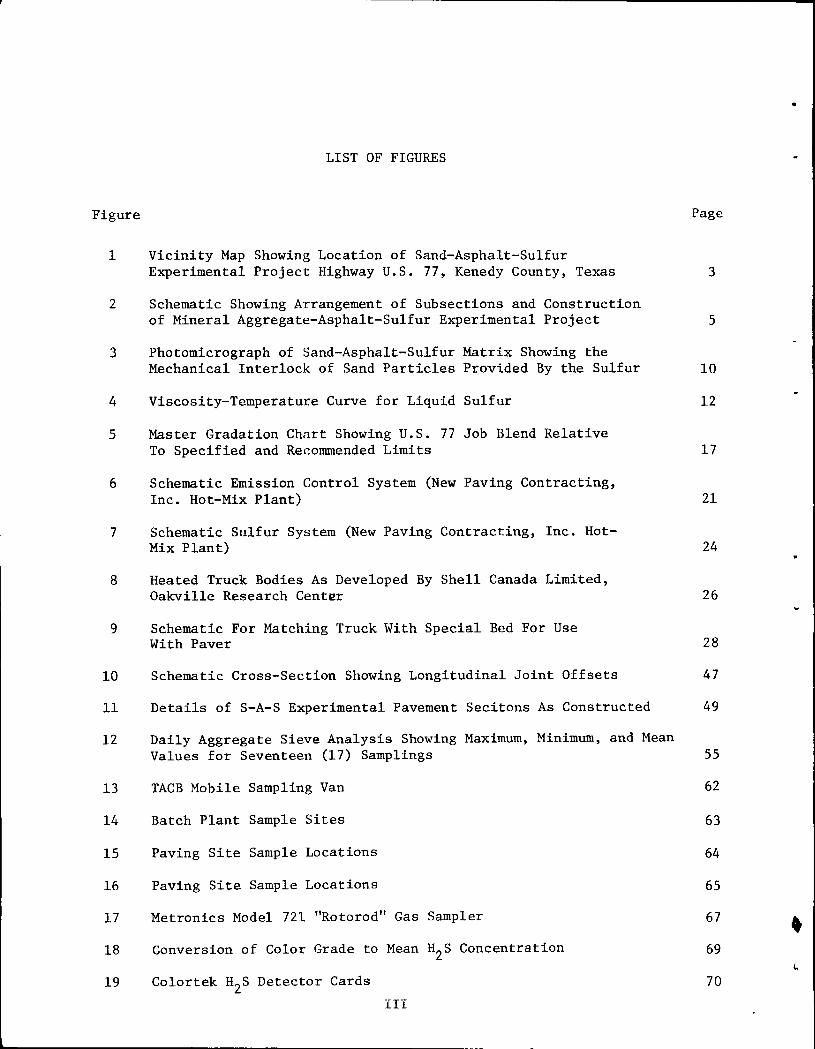
1 Vicinity Map Showing Location of Sand-Asphalt-Sulfur Experimental Project Highway U.S. 77, Kenedy County, Texas
2 Schematic Showing Arrangement of Subsections and Construction of Mineral Aggregate-Asphalt-Sulfur Experimental Project
3 Photomicrograph of Sand-Asphalt-Sulfur Matrix Showing the Mechanical Interlock of Sand Particles Provided By the Sulfur
4 Viscosity-Temperature Curve for Liquid Sulfur
5 Master Gradation Chart Showing U.S. 77 Job Blend Relative To Specified and Recommended Limits
6 Schematic Emission Control System (New Paving Contracting, Inc. Hot-Mix Plant)
7 Schematic Sulfur System (New Paving Contracting, Inc. HotMix Plant)
8 Heated Truck Bodies As Developed By Shell Canada Limited, Oakville Research Center
9 Schematic For Matching Truck With Special Bed For Use With Paver
10 Schematic Cross-Section Showing Longitudinal Joint Offsets
11 Details of S-A-S Experimental Pavement Secitons As Constructed
12 Daily Aggregate Sieve Analysis Showing Maximum, Minimum, and Mean Values for Seventeen (17) Samplings
13 TACB Mobile Sampling Van
14 Batch Plant Sample Sites
15 Paving Site Sample Locations
16 Paving Site Sample Locations
17 Metronics Model 721 "Rotorod" Gas Sampler
18 Conversion of Color Grade to Mean H2s Concentration
19 Colortek H2s Detector Cards
III
3
5
10
12
17
21
24
26
28
47
49
55
62
63
64
65
67
69
70
•
•
•
LIST OF TABLES
Table
I Individual Sieve Analysis of Sands and Blends Used On U.S. 77 S-A-S Field Demonstration Project
II Arrangements for Instrumentation
III H2S Emissions At and In the Vicinity of the Hot Mix Plant
IV H2S Emissions At and In the Vicinity of the the Paver
v H2S Emissions at Miscellaneous Locations
VI Summary of Preliminary Laboratory Tests
VII Mix Design Properties 65% Coarse Sand; 35% Fine Sand Blend
VIII Sand-Aggregate Variability
IX Job Variability
X Variability of tUx Temperatures
XI Both Samplings of Sulfur and Asphalt Contents
XII Batch Samplings of Slump Measurements
XIII Daily Batch Samplings of Marshall Stability and Flow
IV
Page
18
60
72
73
74
83
84
86
86
88
90
91
92
SAND-ASPHALT-SULFUR PAVEMENT EXPERIMENTAL PROJECT
HIGHWAY U.S. 77, KENEDY COUNTY, TEXAS
Sponsored By
TEXAS STATE DEPARTMENT OF HIGHWAYS AND PUBLIC TRANSPORTATION
and
THE FEDERAL HIGHWAY ADMINISTRATION, OFFICE OF DEVELOPMENT
in cooperation with
U.S. BUREAU OF MINES
THE SULPHUR INSTITUTE
Other Participants Include:
Barber-Greene Company
Foremost Paving, Inc.
Motheral Contractors, Inc.
Shell Canada Limited
Texas Air Control Board
Texasgulf, Inc.
Texas Transportation Institute
For additional information on sand-asphalt-sulfur paving materials, please contact:
THE SULPHUR INSTITUTE 1725 K Street, N.W. Washington, D.C. 20006
Or other participants.
v
•
..
•
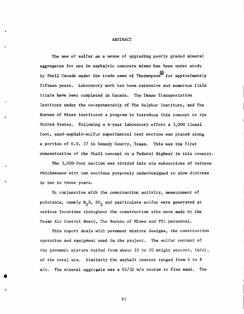
ABSTRACT
The use of sulfur as a means of upgrading poorly graded mineral
aggregates for use in asphaltic concrete mixes has been under study
by Shell Canada under the trade name of Thermopave~ for approximately
fifteen years. Laboratory work has been extensive and numerous field
trials have been completed in Canada. The Texas Transportation
Institute under the co-sponsorship of The Sulphur Institute, and The
Bureau of Mines instituted a program to introduce this concept to the
United States. Following a 4-year laboratory effort a 3,000 lineal
foot, sand-asphalt-sulfur experimental test section was placed along
a portion of u.s. 77 in Kenedy County, Texas. This was the first
demonstration of the Shell concept on a Federal Highway in this country.
The 3,000-foot section was divided into six subsections of various
thicknesses with two sections purposely underdesigned to show distress
in two to three years •
In conjunction with the construction activity, measurement of
polutants, namely H2S, so2 and particulate sulfur were generated at
various locations throughout the construction site were made by the
Texas Air Control Board, The Bureau of Mines and TTl personnel.
This report deals with pavement mixture designs, the construction
operation and equipment used in the project. The sulfur content of
the pavement mixture varied from about 10 to 20 weight percent, (w/o),
of the total mix. Similarly the asphalt content ranged from 4 to 8
w/o. The mineral aggregate was a 65/35 w/o co,trse to fine sand. The
VI
latter was taken from a source local to the construction site. Con
struction operations and equipment are detailed with photographs
where possible.
VII
•
.:
•
INTRODUCTION
1.0 Introduction
Sulfur is unique among our nation's mineral resources in that
it is one of the few materials which will be in abundant supply in
the future. Current projections indicate that by the year 1978 the
supply of sulfur will begin to exceed the demand. For this reason,
various industry, government and university groups have initiated
efforts to develop new uses for sulfur.
One of the most promising outlets for sulfur is highway con
struction in which interest is currently being stimulated by two
factors: (a) the decreasing availability or total absence of quality
aggregates in a number of regions around the country and (b) the current
increase in cost and projected demands for asphalt. Sulfur's unique
properties permit it to be utilized either as a structuring agent
(i.e. play1ng the role of the aggregate) or as an integral part of
the binder or both.
The project described in this report addresses itself specifically
to the use of sulfur in sand-asphalt-sulfur paving mixtures. This
concept was developed and patented by Shell Canada, Ltd. and involves
the use of sulfur as a structuring agent with poorly grades of sands
as found in many areas of the United States and specifically along the
beaches and inland regions of the Gulf Coast States. Through efforts
initiated by The Sulphur Institute and co-sponsored by the U. S.
Bureau of Mines, the Texas Transportation Institute has, during the
1
past four years done considerable laboratory verification studies
of the sand-asphalt-sulfur technology developed in Canada. One of the
prime objectives of this effort was to introduce to the United States
and adapt to her conditions the utilization of sulfur in asphaltic
concrete mixes for bases.
This program culminated during April, 1977, with successful
placement of a 3,000 lineal foot sand-asphalt-sulfur test section on
U.S. 77 in Kenedy County, Texas. Construction details including
materials, mix designs, equipment, materials handling, quality
control and evolved gas emissions analyses will be discussed along
with descriptions of non-conventional operations.
1.1 Location and Scope
The geographical location of the project is shown on the vicinity
map, Figure 1. The location is further described as a portion of
Highway U.S. 77, 5 miles south of Sarita and 46 miles north of
Raymondville in Kenedy County, Texas. This area is under the juris-
diction of District 21 of the Texas State Department of Highways and
Public Transportation.
The beginning and the end, respectively, of the experimental
section are designated by markers on the east right-of-way; i.e.
BEGINNING (END) SAND-ASPHALT-SULFUR DEMONSTRATION
The sand-asphalt-sulfur experimental pavement base was placed on
the two right N-S lanes between station 1985/00 and 2015/00, Highway
Project TQF 913(13) Kenedy County, Texas, District 21.
2 •
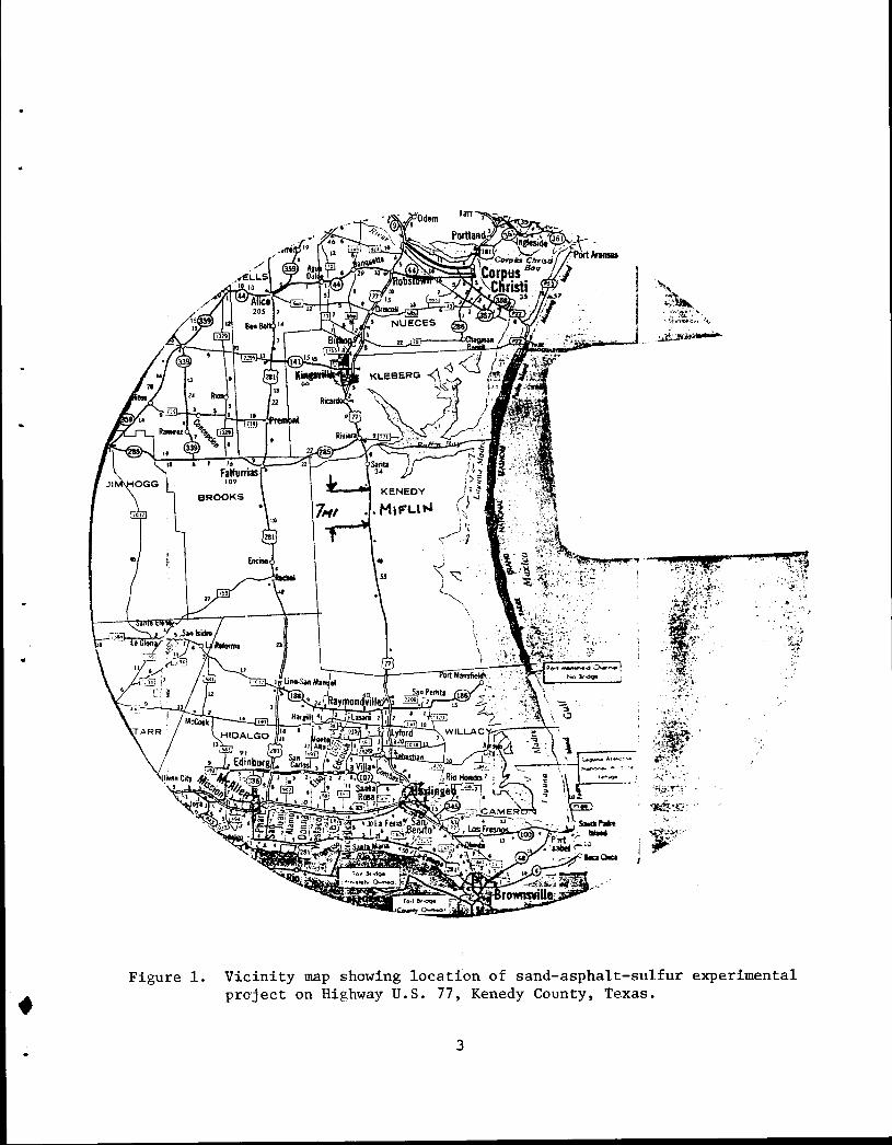
Figure 1.
•
"~,:: .... :· ~~~~~-~~-
. ~ ..
Vicinity map showing location of sand-asphalt-sulfur experimental project on Highway U.S. 77, Kenedy County, Texas •
3
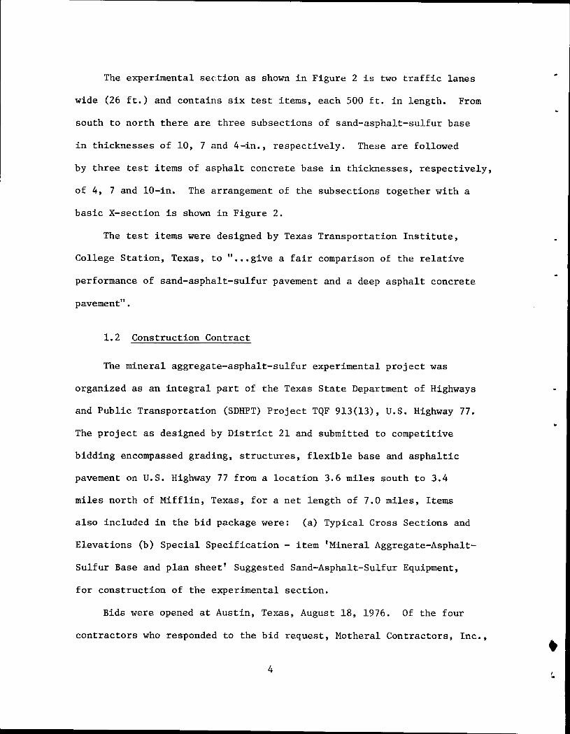
The experimental section as shown in Figure 2 is two traffic lanes
wide (26 ft.) and contains six test items, each 500ft. in length. From
south to north there are three subsections of sand-asphalt-sulfur base
in thicknesses of 10, 7 and 4-in., respectively. These are followed
by three test items of asphalt concrete base in thicknesses, respectively,
of 4, 7 and 10-in. The arrangement of the subsections together with a
basic X-section is shown in Figure 2.
The test items were designed by Texas Transportation Institute,
College Station, Texas, to " ••• give a fair comparison of the relative
performance of sand-asphalt-sulfur pavement and a deep asphalt concrete
pavement".
1.2 Construction Contract
The mineral aggregate-asphalt-sulfur experimental project was
organized as an integral part of the Texas State Department of Highways
and Public Transportation (SDHPT) Project TQF 913(13), U.S. Highway 77.
The project as designed by District 21 and submitted to competitive
bidding encompassed grading, structures, flexible base and asphaltic
pavement on U.S. Highway 77 from a location 3.6 miles south to 3.4
miles north of Mifflin, Texas, for a net length of 7.0 miles, Items
also included in the bid package were: (a) Typical Cross Sections and
Elevations (b) Special Specification - item 'Mineral Aggregate-Asphalt-
Sulfur Base and plan sheet' Suggested Sand-Asphalt-Sulfur Equipment,
for construction of the experimental section.
Bids were opened at Austin, Texas, August 18, 1976. Of the four
contractors who responded to the bid request, Motheral Contractors, Inc., • 4

!Jl
•
Beginning Project Station 1985,£00
~ :_· ... ·-~ ..... ~ .... '.·:· ..:·· ..
4
1"-Asphalt Concrete Paving_{Type D) @ 10011/S.Y.
~t·: 4" S-A-S 4" A C 7" A C
End Project Station 2015fOO
10" F.B. ~.:::' 10" S-A-S 7" S-A-S ·~~·:::~~
"0 ... ~.1 ·~
o· b.~ ·~·"~:::1110" 10" A C J, F.B.
0 0
+ Ll) 00 a.. .-t
t---2.5~
8-Inches
500'
0 0
+ 0 a.. a.. .-t
Lime Treated
500' ' f' 0 0
+ Ll) a.. a.. .-t
Sub grade
500' ., .. 0 0
+ 0 0 0 N
36' Asphalt Concrete Surfacing @ 10011/S.Y. ---1 15.5'
t- 12.5' + Variable Thickness See Elevation
8" Lime Treated Subgrade
Cross-Section N-S Right Lanes
8-Inches
500'
0 0
+ Ll)
0 0 N
Lime Treated Sub grade
500' . I· 500'
0 0
+ 0 .-t 0 N
Notes:
S-A-S Sulfur-Asphalt-Sand Paving Material
AC Asphalt Concrete
F.B. Flexible Base (caliche)
Schematic Is Not Down To Scale
Figure 2. Schematic Showing Arrangement of Subsections and Construction of Mineral Aggregate-Asphalt-Sulfur Experimental Project
0 0
+ Ll) .-t 0 N
Weslaco, Texas, submitted the lowest cost ($1,394,110.52), was
therefore awarded the contract on September 17, 1976. In turn,
Motheral entered into a sub-contract with Foremost Paving, Inc.,
Weslaco, Texas, for the construction of asphalt concrete and the
sand-asphalt-sulfur test items. The project was awarded to the low
bidder, Motheral Contractors, Inc., on September 15, 1976.
1.3 Participants
The mineral aggregate-asphalt-sulfur experimental project was
made possible through the participation of many groups:
Texas State Department of Highways and Public Transportation,
Austin and District 21, Pharr, Texas.
The Federal Highway Administration, Implementation Division,
Washington, D.C. and the Regional Offices, Fort Worth,
and Austin, Texas.
The U. S. Bureau of Mines, Washington, D.C. and Boulder City
Metallurgy Engineering Laboratory, Nevada.
The Sulphur Institute, Washington, D.C.
Shell Canada Limited, Oakville Research Centre, Oakville and
Products Application, Toronto.
Texasgulf, Inc., Houston and Newgulf, Texas.
Barber-Greene Company, Inc., Aurora, Illinois.
Motheral Contractors, Inc., Weslaco, Texas.
Foremost Paving, Inc., Weslaco, Texas.
New Paving Contracting, Inc., Seguin, Texas.
6
•
•
Texas Air Control Board, Austin, Texas.
Texas Transportation Institute, College Station, Texas.
The engineering construction of the experimental project was under
the immediate supervision of G. J. (Lupe) Camargo, Supervising Resident
Engineer, State Department of Highways and Public Transportation,
Raymondville, Texas. G. G. Garcia, District Engineer, Wade D. Barnes,
Assistant District Engineer and Jack T. Trammell, Senior Laboratory
Engineer, provided assistance and supervision in their respective
fields.
The contractor's operations were under the supervision of Eddie F.
Forshage, Owner, Foremost Paving, Inc. He was assisted by Parker New,
Plant Superintendent and Pete Leal, Paving Foreman.
Shell Canada Limited, Oakville Research Centre, provided three
engineering consultants: Imants Deme at the paver and at the hot-mix
plant, Carl Mohammed at the hot-mix plant and Charles E. Spurr on heated
dumpbody trucks.
Texas Transportation Institute was represented by B. M. Gallaway
and Don Saylak co-principle investigators of the over-all study and
technicians R. Barnett, N. Little and E. Ellis.
Texas Air Control Board monitored the project for possible air
contaminants.
W. H. Richardson, Texasgulf, Inc., supervised the design and
operation of the sulfur system at the hot-mix plant.
Kenneth J. Rudolph, Barber-Greene Company, supervised the
modifications of the B-G paver .
7
Wm. C. McBee, Bureau of Mines, provided instrumentation for
measuring sulfur gases and assisted D. Saylak with the measurements.
1. 4 Sand-Asphalt-Sulfur Pavement Material
A sand-asphalt-sulfur (S-A-S) pavement material is composed of
mineral aggregate (sand), elemental sulfur and asphalt in which by
weight, the amount of sulfur is equal to or exceeds that of the
asphalt. The sulfur content in the sand-asphalt-sulfur pavement
mixture varied from about 10 to 20 percent by weight, the asphalt
content from about 4 to 8 percent by weight and the sand from 72 to
86 percent by weight accordingly.
The sand-asphalt-sulfur pavement concept was developed by Shell
Canada Limited, Oakville Research Centre. Shell with assistance from
Blaw-Knox and Barber-Greene developed the construction equipment and
construction procedures which were used for preparing and placing
the pavement mixture.
1.5 The Need
In many of the "severe problem aggregate areas" of the United
States, sand is found in abundance while coarse aggregates are being
depleted at an alarming rate. At the same time, the Clean Air Acts
of 1963 and 1970-73 required the removal of sulfur from fossil fuels
to the extent of an anticipated sulfur surplus. Sulfur and sand can
replace coarse aggregate, a potentially scarce product.
A comparison of the unit weight and volumes of S-A-S components
with those found in conventional asphalt pavement is given below:
8
,
•
"
•
•
..
..
...
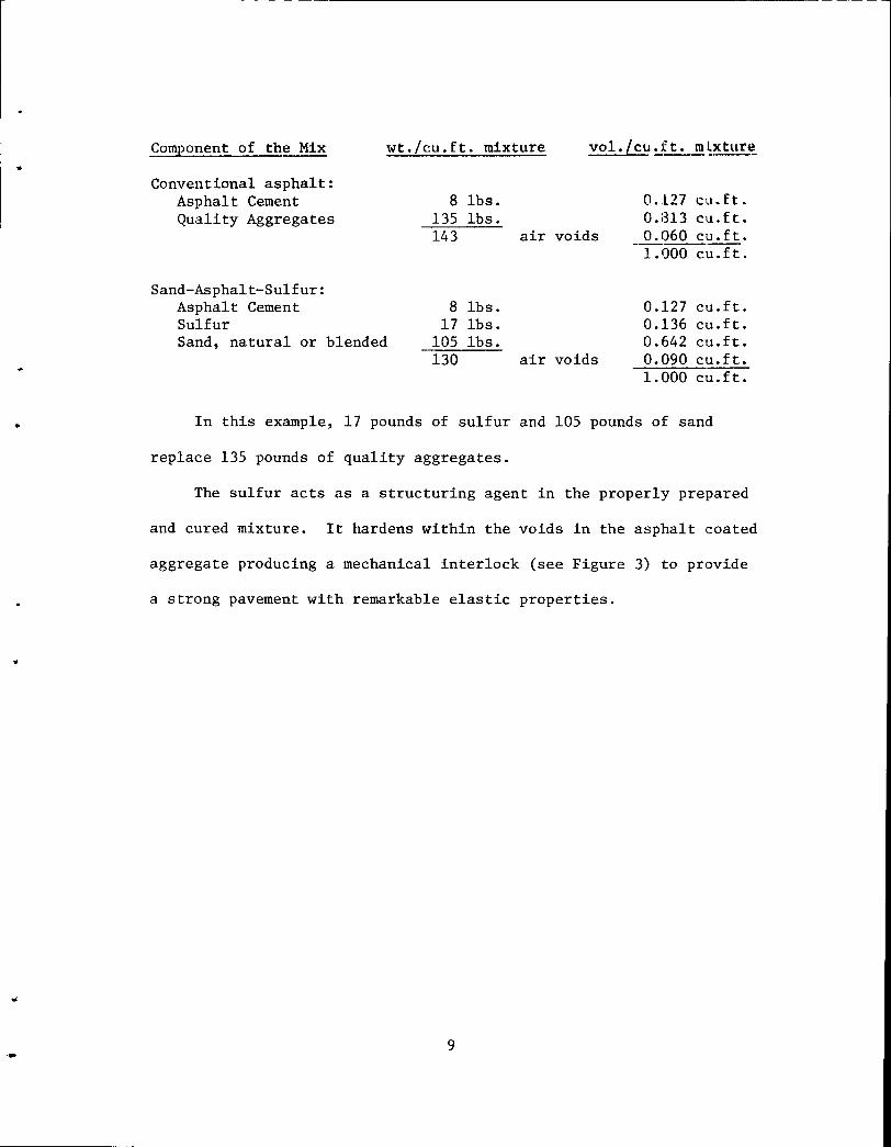
Component of the Mix wt./cu.ft. mixture vol./ cu~J t • ..!!! ~~ ture
Conventional asphalt: Asphalt Cement Quality Aggregates
Sand-Asphalt-Sulfur: Asphalt Cement Sulfur Sand, natural or blended
8 lbs. 135 lbs. 143 air voids
8 lbs. 17 lbs.
105 lbs. ----130 air voids
0.127 cu. ft. 0.:313 cu.ft. 0.060 cu. ft. 1.000 cu.ft.
0.127 cu.ft. 0.136 cu.ft. 0.642 cu.ft. 0.090 cu. ft. 1.000 cu.ft.
In this example, 17 pounds of sulfur and 105 pounds of sand
replace 135 pounds of quality aggregates.
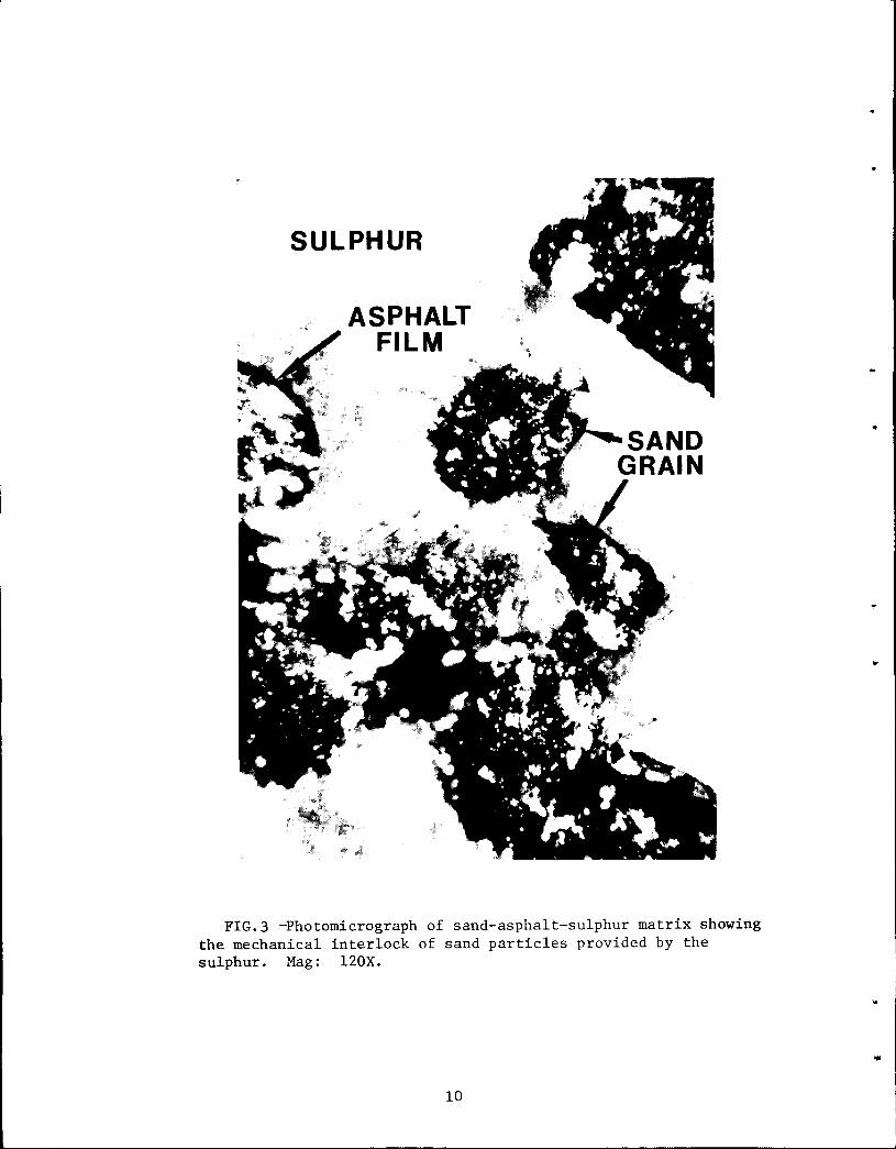
The sulfur acts as a structuring agent in the properly prepared
and cured mixture. It hardens within the voids in the asphalt coated
aggregate producing a mechanical interlock (see Figure 3) to provide
a strong pavement with remarkable elastic properties .
9
SULPHUR
ASPHALT FILM
FIG.3 -Photomicrograph of sand-asphalt-sulphur matrix showing the mechanical interlock of sand particles provided by the sulphur. Mag: 120X.
10
..
..
•
•
•
2.0 Construction Materials
2.1 Sulfur
Sulfur is one of the basic elements, with an atomic number of 16
and atomic weight of 32.06. The specific gravity of solid sulfur is
about 2.00, or twice as heavy as asphalt, at ambient temperatures and
1.80 at 275F.
Sulfur is not considered a hazardous material in commerce. About
90% of the elemental sulfur used in the U.S. is shipped in the liquid
state. Truck transports are widely used with a typical truck hauling a
load of 20 to 22 long tons. Practices for hauling, heating, storage
and safety are well established in the trade.
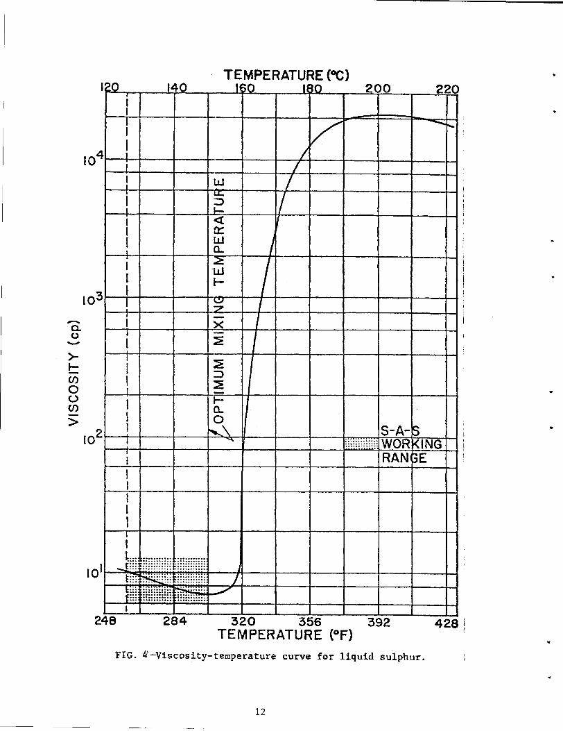
Sulfur melts at about 240F. The working range for molten sulfur
corresponds quite well to the working range for paving grade asphalt;
i.e. 255 to 300F. A temperature-viscosity curve for sulfur is shown
in Figure 4. At higher temperatures, the molten sulfur becomes very
viscous .
When heated, the concentrations of toxic gases formed are low
or nonexistent in the temperature range of 250 to 300F but increase
rapidly as the temperature rises above this range. Sulfur dust and
fumes from molten sulfur can exist within the working temperature range
and can cause eye irritation.
Briefly, liquid sulfur is hot and poses the same dangers in this
respect as hot asphalt or any other hot liquid. Molten sulfur at 300F
will burn in air if ignited and sulfur fumes and hudrogen sulphide
11
-0. 0 ->-1-(/)
0 (..) (/)
>
104
103
102
· TEMPERATURE (OC) ~0 14_0_
i 1~50 200 220
I
: --- ..... '
! I
! i
~4-+---+---~~~--~~-r--~---+---+---4~: I
I
I
! ~~+---+---~=-~--~--~--~---+---+--~~ i
I I I
I I I I
i I
I
l I I
I I I I I
I
·············WORKING ................ ............... S-A-5
RAN~E I I I I I I
I L... ···•·····
101 _t~;; .......... .
~-~~ii( .......... . ~::: mmmg ~:.:::
248 428! 284 320 356 392 TEMPERATURE (°F)
FIG. 4-Viscosity-temperature curve for liquid sulphur.
12
•
•
•
gas will also burn under extreme conditions. As with asphalt handling
and, in particular, liquid asphalts, all sources of ignition such as
smoking, open flames and sparks must not be permitted near the liquid
sulfur.
Safety precautions are well established in the trade. These
include attention to temperature control and measuring and monitoring
the H2S content of the air in the work place during paving operations.
Methods and equipment for these purposes have been developed and
measurements of emissions both in the laboratory and in the fields
have been monitored by Shell Canada, The U. S. Bureau of Mines and TTI.
The results of these measurements taken during the U.S. 77 S-A-S
field trials will be discussed later in this report.
The sulfur was supplied form two sources:
1. Warren Petroleum, A Division of Gulf Oil, ex. Fashing, Texas
2. Texasgulf, Inc., ex. Newgulf, Texas
The sulfur was delivered from both sources by the same two haulers:
1. Oil Transport Company, Abilene, Texas
2. Robertson Tank Lines, Houston, Texas
Sulfur transports were tractor-trailer units (18 wheelers) of
about 3,400 gallon capacities (ca. 22.5 long tons @ 14.91 lbs. per
gallon at 280F). Each unit was equipped with heating coils and steam
jacketed discharge valves.
13
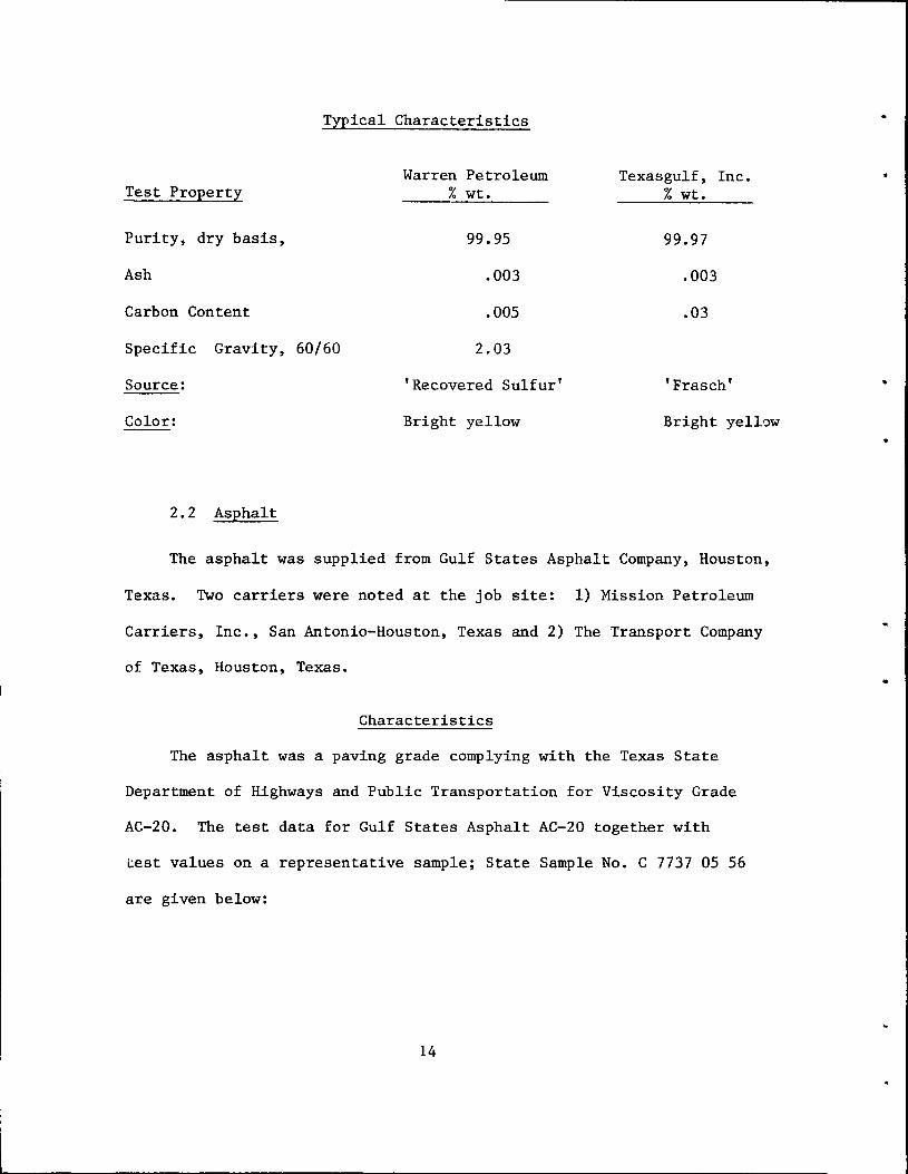
Typical Characteristics
Test Property
Purity, dry basis,
Ash
Carbon Content
Specific Gravity, 60/60
Source:
Color:
2.2 Asphalt
Warren Petroleum % wt.
99.95
.003
.005
2.03
'Recovered Sulfur'
Bright yellow
Texasgulf, Inc. % wt.
99.97
.003
.03
'Frasch'
Bright yellow
The asphalt was supplied from Gulf States Asphalt Company, Houston,
Texas. Two carriers were noted at the job site: 1) Mission Petroleum
Carriers, Inc., San Antonio-Houston, Texas and 2) The Transport Company
of Texas, Houston, Texas.
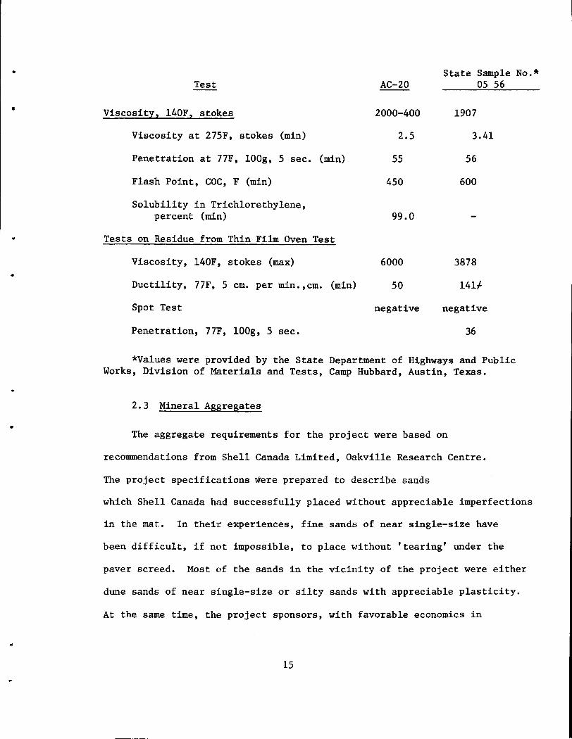
Characteristics
The asphalt was a paving grade complying with the Texas State
Department of Highways and Public Transportation for Viscosity Grade
AC-20. The test data for Gulf States Asphalt AC-20 together with
test values on a representative sample; State Sample No. C 7737 05 56
are given below:
14
•
•
•
..
•
•
•
Test
Viscosity, 140F, stokes
Viscosity at 275F, stokes (min)
Penetration at 77F, lOOg, 5 sec. (min)
Flash Point, COC, F (min)
Solubility in Trichlorethylene, percent (min)
Tests on Residue from Thin Film Oven Test
Viscosity, 140F, stokes (max)
Ductility, 77F, 5 em. per min.,cm. (min)
Spot Test
Penetration, 77F, lOOg, 5 sec.
AC-20
2000-400
2.5
55
450
99.0
6000
50
negative
State Sample No.* 05 56
1907
3.41
56
600
3878
141~
negative
36
*Values were provided by the State Department of Highways and Public Works, Division of Materials and Tests, Camp Hubbard, Austin, Texas.
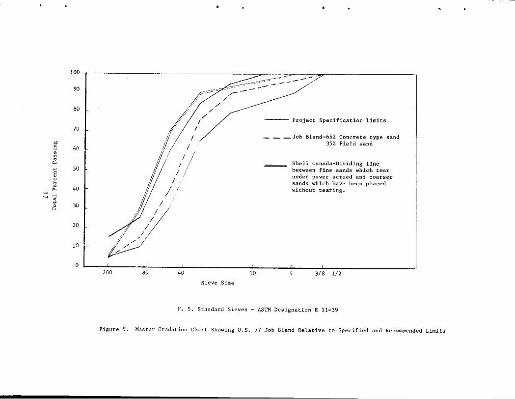
2.3 Mineral Aggregates
The aggregate requirements for the project were based on
recommendations from Shell Canada Limited, Oakville Research Centre.
The project specifications were prepared to describe sands
which Shell Canada had successfully placed without appreciable imperfections
in the mat. In their experiences, fine sands of near single-size have
been difficult, if not impossible, to place without 'tearing' under the
paver screed. Most of the sands in the vicinity of the project were either
dune sands of near single-size or silty sands with appreciable plasticity.
At the same time, the project sponsors, with favorable economics in
15
mind, were interested in using as much local sand as possible. Further
mention will be made of this idea later in the report.
Shell Canada's recommendation on gradation together with the
grading limits selected for the project are shown in Figure 5.
The mineral aggregate selected by the contractor, Foremost Paving,
Inc., consisted of a blend of two sands; 1) a concrete type sand from
Wright Materials Co., 'Bluntzer' Pit on the Nueces River near Corpus
Christi, approximately 55 miles north of the project and 2) a field
sand located about 500 ft. east of the project right-of-way at the
hot-mix plant site, station 2030.
Gradations of 1) preliminary sand samples, 2) the job blend of
65-35% wt. coarse to fine sand and the project gradation limits are
shown in Table 1.
16
•
•
•
100
90
80
70
C>() I: 60 •.-! r:IJ r:IJ ell p..
..., 50 I: a.l t) 1-1 a.l
40 p.. ...... ...._.rl
ell ..., 30 0
E-<
20
10
0 200 80
•
p> I
I
j /
I
I
I I
I
40
Sieve Size
• ..
::;::::::::~~:::-~ ~~· ~-~----------- ----/
10
Project Specification Limits
- _ -Job Blend-65% Concrete type sand 35% Field sand
Shell Canada-Dividing line between fine sands which tear under paver screed and coarser sands which have been placed without tearing.
4 3/8 1/2
U. S. Standard Sieves - ASTM Designation E 11-39
r
Figure 5. Master Gradation Chart Showing U.S. 77 Job Blend Relative to Specified and Recommended Limits
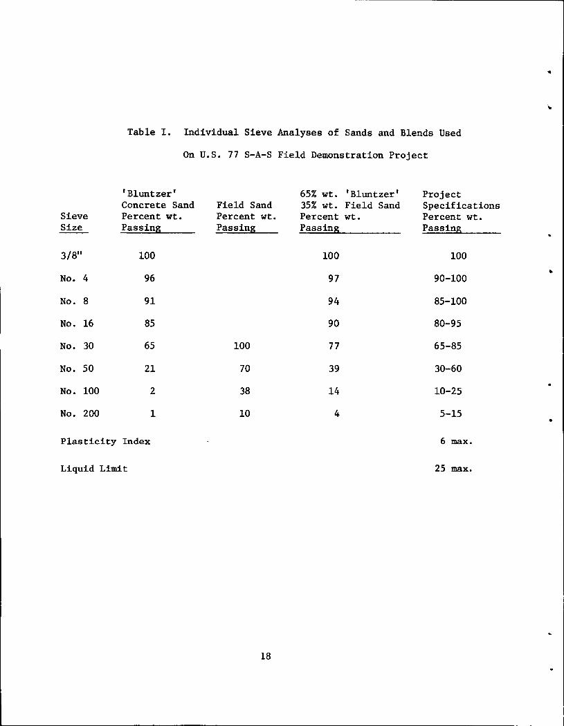
Table I. Individual Sieve Analyses of Sands and Blends Used
On U.S. 77 S-A-S Field Demonstration Project
'Bluntzer' 65% wt. 'Bluntzer' Project Concrete Sand Field Sand 35% wt. Field Sand Specifications
Sieve Percent wt. Percent wt. Percent wt. Percent wt. Size Passing Passing Passing Passing
3/8" 100 100 100 ..
No. 4 96 97 90-100
No. 8 91 94 85-100
No. 16 85 90 80-95
No. 30 65 100 77 65-85
No. 50 21 70 39 30-60
No. 100 2 38 14 10-25
No. 200 1 10 4 5-15 •
Plasticity Index 6 max.
Liquid Limit 25 max.
18
•
•
..
3.0 Contractor Equipment
3.1 General
The sand-asphalt-sulfur pavement mixtures were prepared in a
conventional stack-up type hot-mix batch plant which was equipped
with auxiliary stystems for handling the molten sulfur. The hot
asphalt and molten sulfur are transferred from separate storage by
approved pumps into the weigh bucket. The dried and heated mineral
aggregate (sand) is weighed into the pug-mixer. The required amount of
hot asphalt and the required amount of molten sulfur for each batch
are introduced into the mixer in that sequence and mixing continued as
required to prepare a uniform paving material. The mix is loaded into
trucks with heated dump bodies to maintain the temperature within the
working range. Pavers must be altered to permit the screed to be fully
supported for strike-off smoothing and consolidation of the comparatively
soft paving mixture. Placement is carried out in lifts of 3 inches maximum
thickness without rolling or subsequent compaction. Details of each
phase of the operation are given below.
3.2 The Hot-Mix Plant
The hot-mix plant used for the preparation of sand-asphalt-sulfur
pavement mixture was a Standard, portable, 2,000 lb., batch stack-up
type with a 3,000 lb. mixer; Serial Number 2045 (or 2046). The plant
was manufactured by Standard Steel Corporation, now widely known as
Stan Steel, a division of Allis Chalmers, 5001 South Boyle, Los Angeles,
California. It consisted of the basic units only; a cold feed elevator,
19
5 ft. diameter x 24 ft. long dryer, hot elevator, screens, bins,
aggregate weight hopper, asphalt weight bucket and mixer. The plant was
manually operated.
This hot-mix plant was manufactured and sold to the original owner
in 1951. It was leased for the project by the sub-contractor, Foremost
Paving, Inc., from New Paving Contracting, Inc., Seguin, Texas.
The hot-mix plant was dismantled from a project near Fort Worth,
Texas and truck-hauled (one or more parts per load) to the project site
25 miles South of Kingsville, Texas. It was reassembled for use on
a lot east and immediately adjacent the project right-of-way at station
2030. The erection and operation of the plant were supervised by Mr.
Parker New, co-owner of New Paving Contracting, Inc.
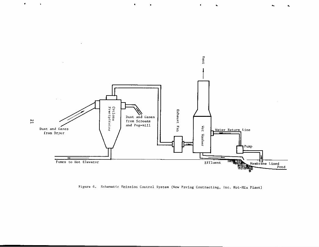
3.2.1. Emission Control
The emission control system consisted of an 8 ft. diameter cone
precipitator, part of the original equipment, and a wet washer supplement.
Water for the scrubber (washer) was truck-hauled to the site and dis
charged into a membrane lined pond. The pond doubled for sludge disposal
and water storage. A small pump returned water from the surface of the
pond to the washer in a continuous circulating system.
The emission control system is shown schematically in Figure 6.
3.2.2. Cold Aggregate Feed
The coarse sand and the fine sand were stored in separate stockpiles
on the site. A caterpillar front-end loader was used to transfer the
sands to a twin, 2-compartment (four compartments total) portable steel
bin. One-half was used for coarse and one-half for fine sand. The
20
•
N .....
&
from Dryer
Fumes to Hot Elevator
•
Gases
t"l >< ::T Ill c:: CIJ rt
"1 Ill ::l
~
< ~ rt
t
::;:; It> rt
~ CIJ ::T It> 'i
Effluent
Figure 6. Schematic Emission Control System (New Paving Contracting, Inc. Hot-Mix Plant)
...
Lined Pond
...
-- ------------------------
aggregate feeder system consisted of manual gates with reciprocating
feeders and an continuouH belt conveyor to the cold feed bueket line.
Vibrators were attached to the side of each sand bin. The cold feed
elevator discharged into a funnel leading to the dryer.
3.2.3. Electric Power
Electric power for the hot-mix plant was provided by portable
generators. One was a Caterpiller diesel, 210 kw., 60 cycle unit.
3.2.4. Asphalt System
Asphalt was stored in a salvaged horizontal railroad tanker with
a rated capacity of 8,145 gallons. It was equipped with the usual
heating coils and a recording thermometer.
Asphalt was pumped to the weigh bucket in a full circulating system.
It included a 3-inch hot oil jacketed Viking gear pump and manually
operated 3-way valve at the weigh bucket. A 3-inch flexible hose (some
segments were Teflon stainless steel) without heat or insulation was
used on the suction and return lines.
Hot oil was provided by a Childress Oil Heater rated at 1500 BTU/Hr.
A 3 Hp. electric driven centrifugal pump was used for circulating the oil.
The oil temperature was maintained at about 400F which kept the asphalt
in storage at 290-300F.
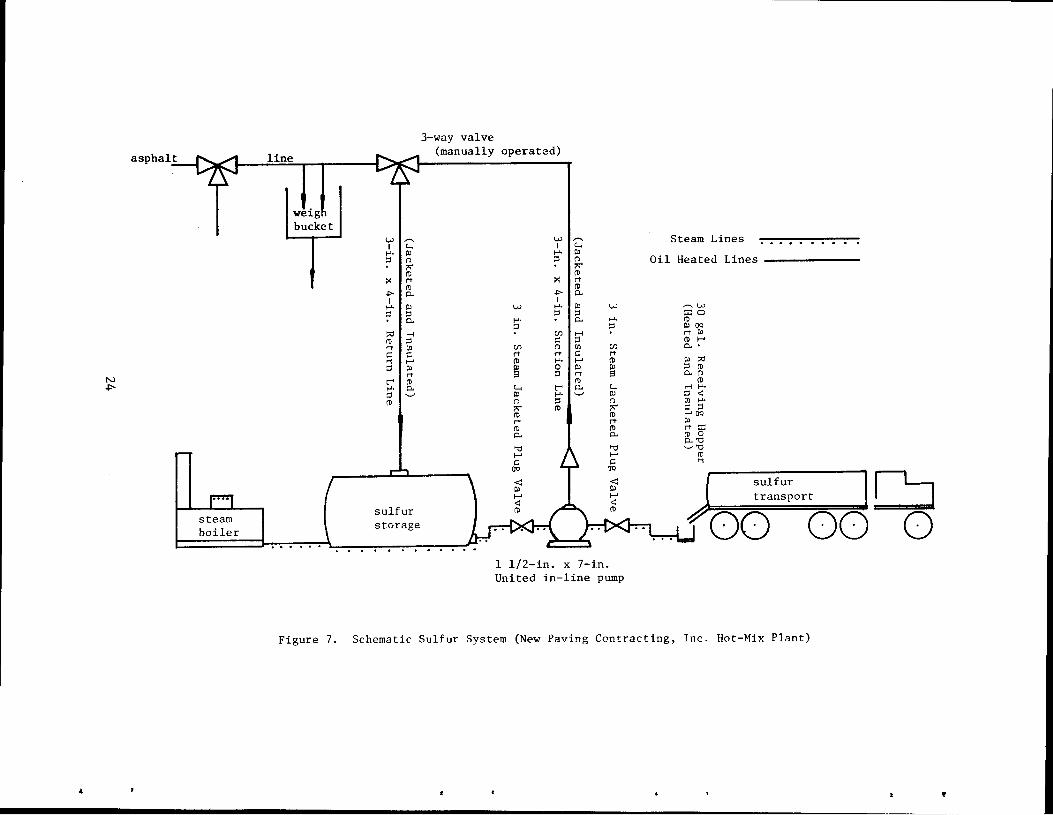
3.3 The Sulfur System
The sulfur system was designed by Mr. W. H. Richardson, Sr. Engineer,
Texasgulf Inc., Newgulf, Texas. It was constructed by Mr. Parker New,
Superintendent, with assistance from Mr. Richardson.
Texasgulf provided much of the basic sulfur handling equipment and
transported it to the construction site in a U-Haul trailer. Items
22
\
•
..
..
• provided by Texasgulf included:
1. A 1 1/2 x 7 inch United In-Line Pump, 120 gpm, 75 ft. head with
10 Hp. 220 volt electric motor,
2. Two 3-inch steam jacketed plug valves,
3. One 4-inch Mission check valve and
4. All steam jacketed pipe and fittings on pump unit.
Items provided by the contractor included:
1. Sulfur storage tank
2. 3 way valve at weight bucket
3. Approximately 100 lineal feet of 3 by 4-inch jacketed pipe for
suction and return lines
4. Foil backed 4-inch insulation mats
The sulfur storage facility consisted of a used, horizontal 10 ft. diameter
by 30ft. long insulated tank with a calculated capacity of 17,6000 gallons.
The storage tank was heated with hot oil.
The sulfur pump, attached pipe valves, and fittings, receiving hopper
and sulfur transports (as needed) were steam heated. Steam was generated
by a skid mounted oil-fired boiler rated at 25 Hp. It was manufactured
by Murray Iron Works, "Turbines and Boilers", Burlington, Iowa.
A schematic of the sulfur system is shown in Figure 7.
3.4 Special Heated Truck Bodies
The sand-asphalt-sulfur pavement material was hauled in heated
dump truck bodies to prevent the formation of cold lumps.
The sand-asphalt-sulfur pavement material was transported, an average
distance of about 3/4 miles, from the hot-plant located east and adjacent the
project right-of-way at station 2030 to the roadway on U.S. 77, in four
trucks equipped with special heated bodies constructed of aluminum. This
23
N .p..
"
asphalt
steam boiler
line
weig bucket
I
w~~ I c..., ..... "' ::s (")
"' ro >: rt
ro ..,. p.. I ..... "' ::s ::s
p..
::0 H ro ::s rt 00 ~ ~ '1 1-' ::s "' rt t"" ro ..... p.. ::s '-" ro
sulfur storage
3-way valve (manually operated)
w ,...... I c...,
..... "' ::s (")
"' ro >: rt
ro ..,. p.. I
w ..... "' ::s ::s ..... p.. ::s
C/) H ~ ::s
C/) (") 00 rt rt ~ ro ..... ...... ~ 0 "' ::s rt
ro c..., t"" p..
"' ..... '-' (") ::s ~ ro ro rt ro p..
'U ...... ~
()Q
w ..... ::s
C/)
rt ro
"' s c...,
"' (")
~ ro rt ro p..
'U ...... ~
()Q
Steam Lines
Oil Heated Lines -------
~w
::r:o ro PJOQ
rt "' ro ...... P..•
"' ::0 ::s ro P..t"l
ro H t-'· ::s <: 00 ..... ~ ::s 1-'0Q
"' rt::t: ro o P..'"O '-' '1j
ro '1
sulfur transport ~ .C:J
...... ....-'! • 00 00 0 d__j . . . . .
1 1/2-in. x 7-in. United in-line pump
Figure 7. Schematic Sulfur System (New Paving Contracting, Inc. Hot-Mix Plant)
"
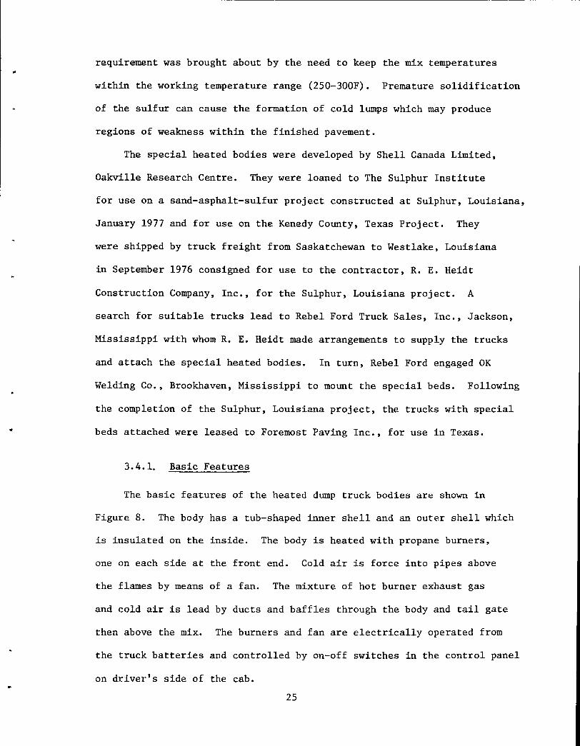
requirement was brought about by the need to keep the mix temperatures
within the working temperature range (250-300F). Premature solidification
of the sulfur can cause the formation of cold lumps which may produce
regions of weakness within the finished pavement.
The special heated bodies were developed by Shell Canada Limited,
Oakville Research Centre. They were loaned to The Sulphur Institute
for use on a sand-asphalt-sulfur project constructed at Sulphur, Louisiana,
January 1977 and for use on the Kenedy County, Texas Project. They
were shipped by truck freight from Saskatchewan to Westlake, Louisiana
in September 1976 consigned for use to the contractor, R. E. Heidt
Construction Company, Inc., for the Sulphur, Louisiana project. A
search for suitable trucks lead to Rebel Ford Truck Sales, Inc., Jackson,
Mississippi with whom R. E. Heidt made arrangements to supply the trucks
and attach the special heated bodies. In turn, Rebel Ford engaged OK
Welding Co., Brookhaven, Mississippi to mount the special beds. Following
the completion of the Sulphur, Louisiana project, the trucks with special
beds attached were leased to Foremost Paving Inc., for use in Texas.
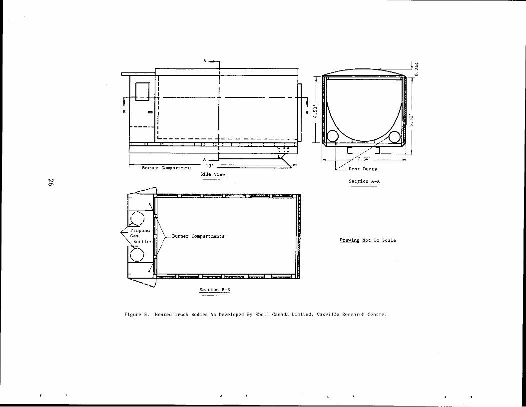
3.4.1. Basic Features
The basic features of the heated dump truck bodies are shown in
Figure 8. The body has a tub-shaped inner shell and an outer shell which
is insulated on the inside. The body is heated with propane burners,
one on each side at the front end. Cold air is force into pipes above
the flames by means of a fan. The mixture of hot burner exhaust gas
and cold air is lead by ducts and baffles through the body and tail gate
then above the mix. The burners and fan are electrically operated from
the truck batteries and controlled by on-off switches in the control panel
on driver's side of the cab.
25
N 0\
A
I
I I I I I I I L-------- ---
A
Burner Compartment 13'
Side View
-__ ..,
r ___j
.... -,
~LD-Gas Burner Compartments Bottles
;r::: ... , I I '~
L ' ---....) Section B-B
---- T ;-.,
B "' -.:t
l
-.:t
---------------==-----~ ~
Section A-A
Drawing Not To Scale
1 0
"' U"\
0
Figure 8. Heated Truck Bodies As Developed By Shell Canada Limited, Oakville Research Centre.
-~
-
The body is equipped with a removal cover which has flaps for
loading purposes. The aluminum body weighs 3,800 lbs. Capacity loads
are 14-15 tons of sand-asphalt-sulfur pavement mixture.
3.4.2. Truck Mounting
The special heated truck bodies, as constructed, can be mounted on
tandem-axle asphalt dump trucks having 14 ft. dump bodies and equipped
with front mount hoists of the Edbro type or equipped with underbody
hoists. They will not work with the tandem-axle asphalt dump trucks
commonly used in the Louisiana-Texas areas which have 13-13.5 ft. dump
bodies and telescopic hoists attached to the top front of the body
requiring body recesses known locally as "dog boxes".
Figure 9 shows schematically some dimensions to be used as a guide
for matching the trucks and the special beds for use with a paver.
3.4.3. Hoists
The hoists selected by OK Welding were underbody type ''Twin Telescopic"
hoists Model 498, 102-inch truck cab to axle (cab to midpoint between
rear axles), manufactured by Perfection-Cobey Company, Galion, Ohio
and sold and distributed by OK Welding. These hoists are designed
for outside frame mounting or inside frame mounting an unique feature
which accommodates many space restrictions.
3.4.4. Trucks
Rebel Ford provided re-built trucks of the following makes and
types. Shown also are Shell Canada's designations for the special
27
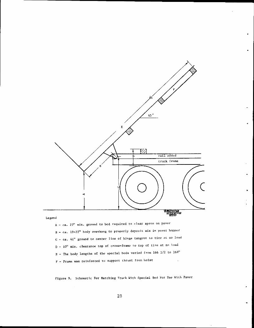
A - ca. 27" min. ground to bed required to clear apron on paver
B - ca. 19-22" body overhang to properly deposit mix in paver hopper
C - ca. 41" ground to center line of hinge tangent to tire at no load
D - 10" min. clearance top of cross-frame to top of tire at no load
E - The body lengths of the special beds varied from 166 1/2 to 168"
F - Frame was reinforced to support thrust from hoist
Figure 9. Schematic For Matching Truck With Special Bed For Use With Paver
28
..
heated bodies.
Manufacturer Description Special Bed
Ford 9000
Chevrolet C65
Ford 880
Ford 880
Tandem-axle diesel HTB 2-A (aluminum)
Tandem-axle gasoline HTB 3-A
Tandem-axle diesel HTB 4-A
Tandem-axle gasoline HTB 5-A
OK Welding modified the trucks as necessary for mounting the
special heated beds. The Chevrolet C65 has a 13.5 ft. dump body
II
II
II
and the chasis was not suitable. The ladder on the front of the special
bed had to be removed to make room between the front end of the body and
the cab. The Ford 880, gasoline, had a 13.0 ft. dump body. It was
"stretched" by cutting and welding inserts into the frame and replacing
the driveshaft. OK Welding increased the height of the truck rails
when required and reinforced the under body frames; Figure 9 see
Dimensions D and F, respectively •
OK Welding is affiliated with Perfection-Cobey Co., which operates
a new truck body factory nearby. Perfection-Cobey provide, a computer
analyses of the truck-body-hoist system. Measurements for each truck
were so analyzed.
3.4.5. Transportation
The trucks with the special bodies were picked up at Brookhaven and
delivered by R. E. Heidt Construction Company to the Sulphur, Louisiana
project, January 1977. There each of the truck beds were fitted with two
100 lb. capacity propane bottles. Upon completion of the Louisiana
29
project the trucks were made available to Foremost Paving Inc., who
picked them up at Westlake, Louisiana and drove them to the Kenedy
County project in late March 1977. Upon completion of the project,
April 1977, the trucks were picked up by Rebel Ford and returned to
OK Welding for detachment of the special beds for return to Canada.
3.5 Paver - Modifications
The hot sand-asphalt-sulfur pavement mixtures are soft and plastic
at the time of placement. They will not usually support the weight of the
floating screed assembly on the conventional paver. The screed must be
fully supported for strike-off, smoothing and consolidation. No supple
mental rolling of the mixture is required for compaction.
3.5.1. Modification Kit
Barber-Green Company, Aurora, Illinois, in cooperation with Shell
Canada Limited, Oakville Research Centre, have developed a modification
kit suitable for use with Barber-Greene Model Series 100 "Matmakers".
Basically, it consists of double-acting rams mounted at the rear end of
the paver frame and to the levelling arms using specially designed
brackets. The rams and, in turn, the screed, are controlled by a
slightly modified automatic system. In this way, upward lift and down
ward pressure are balanced for the designed layer thicknesses. The
Grad-Line, Inc., Woodinville, Va., was used to control the grade and slope
during paving. The system included a summing circuit, and electronic
control component, developed in cooperation with Shell Canada Limited.
The slope controller and grade controller were moved to the trailing edge
of the screed.
30
•
3.5.2! Paver Characteristics
The paver provided by the contractor, Foremost Paving, Inc., was
a Barber-Greene "Matmaker" Model SB-170, Rubber-Tired Interstate
Finisher equipped with automatic grade and slope controls. This paver
has a standard paving width of 10 ft. With cut-off shoes and extensions,
the width can be changed for a range of widths from 8 to 28 ft. The
Traveling Grade Reference Unit consisted of pin connected random length
aluminum beams, mounted on eight dual runner sleds, attached to three
10'-0" length beams with string line support posts and line.
Modifications: Barber-Greene furnished their modification kit to
the contractor. The mechanism was installed by the contractor under
the supervision of Barber-Greene and Shell Canada Engineers. Other
modifications necessary for the handling of the soft, sand-asphalt-sulfur
mixture were also made.
A front endgate was provided to keep the soft mixture from flowing
forward out of the hopper. It consisted of heavy composition belting
supported vertically with heavy flexible cable loops the ends of which
were attached to the leading edges of the hopper and wings in such a
way that movement of the wings was not restricted.
Two n1ain frame extensions consisting of two one-foot segments each
were constructed by the contractor under the supervision of the Barber
Greene engineer. These became a part of the modification kit.
The auger chamber was enclosed by extending the main frames for the
screed extensions on either side. The feeder switches were relocated
between the main frame extensions and turned to work in the direction of
31
paving. A larger paddle was used in order to float on the soft mixture.
Side plates were used on the free ends of the screed to prevent
"dribbling" of the soft mixture to the side. The plates sloped inward
to provide some edge consolidation.
The hopper and wings were lined with 3/4" plywood in an effort to
insulate the hopper and reduce cooling and formation of lumps.
32
..
----------------------
4.0 Construction Features
4.1 Sulfur Handling
4.1.1. Asphalt Contamination
The sulfur tank was gauged prior to use and found to contain a
depth of 22 inches of paving grade asphalt which calculated to be
2,200 gallons. It could not be drained readily since heating failed to
liquify the material below the heating coils. The hot liquid asphalt
in the top layers was pumped out as much as possible using an asphalt
distributor (pump and tank) with the suction line placed overhead into the
dome of the tank. A gauged 1,150 gallons, 14-inches still remained after
pumping and was left in the tank. There was some reasoning that after
additions of the hot molten sulfur (Specific Gravity - 2.0) the residual
asphalt (Specific Gravity - 1.0) would rise to the surface and that
contamination from any turbulent mixing in the tank would be minimal.
The pavement mix design required 6.2% weight percent (w/o) asphalt and
13 w/o of sulfur.
During construction, attempts were made to check on the amounts of
asphalt contamination. On April 13th., with the gauged sulfur depth at
30 in. (3,440 gallons) in the tank, a sample was taken from the outlet,
cooled and weighed in air and in water. The composition, as calculated,
was 80 w/o sulfur and 20 w/o asphalt. This high asphalt content was
questioned due to the probability of discrete air voids in the sample. A
concurrent sample of the pavement mixture, analyzed in the field laboratory,
showed an asphalt content of 6.8 w/o versus a designed content of 6.2 w/o.
33
4.1.2. Steam Boiler
Start-up of the sand-asphalt-sulfur paving operations was delayed
one day, April 5th., largely due to problems with the steam boiler.
It was fired up late in the afternoon on 4 April with a targeted
pressure of 60 psig. Pressures varied out-of-control from an observed
0 to 125 psig during which the boiler "popped-off" at 150 psig. The
condensate from the steam shorted out the electric motor on the nearby
oil heater. The boiler developed a leak due to the melting of a soft
plug; or so it was reasoned. The electric motor was replaced and the
boiler repaired and operation resumed late the next day (5 April).
Boiler operation was erratic throughout the project. Gauge pressures
fluctuated from an observed 40 to 120 psig. The oil burner was not easily
regulated and this accounted for the erratic operation. Despite this
irregular operation, the steam supply, after start-up April 6th., was
adequate to keep the sulfur pump, pipe and auxiliary equipment operative
and provide steam for the sulfur transports, as required.
4.1.3. Sulfur Tank Capacity
There was some question about the structural integrity of the sulfur
tank which had been used solely for asphalt service. There was some
concern that the tank might rupture if filled with sulfur whose weight
per unit volume is double that of asphalt. It was described that the
amount of sulfur in the tank at any one time would be limited to one-half
tank capacity and sulfur deliveries scheduled accordingly. No problems
were encountered.
34
..
..,· 4.1.4. Transport Handling
The first sulfur transport, ex Warren Petroleum, and 18 wheeler with
a Mack tractor, arrived about noon on 4 April, with an invoiced load of
47,800 lbs. (3,200 Gals.). The temperature was measured at 272F.
It could not be unloaded at that time due to problems with the steam
boiler discussed above. At 5:45pm., it was returned to Warren Petroleum
for steaming. It was reasoned that the temperature of the sulfur would
fall an estimated 1/2 degree hr., perhaps to the solidification point
before unloading would be completed.
The above transport returned the next day (5 April) about 5:00 pm.
The temperature of the sulfur was 276F. The transport was positioned
and put on steam for about an hour. The temperature rose to 292F. The
transport was unloaded by gravity flow into the receiving hopper thence
by pumping through the system into the dome of the sulfur storage tank.
Sulfur unloading took 24 minutes and was accomplished without problems.
The liquid level in the storage tank was depth gauged at 34 inches for
a calculated 4,100 gallons. The total gallons of sulfur unloaded by
difference (4,100 minus the 1,150 gallons of asphalt) was 2,950 gallons.
The difference of 250 gallons between the amount invoiced and the amount
gauged in the storage tank was attributed to clingage in the transport
and to possible inaccuracies in gauging since the tank has not been
calibrated to correct for volume occupied by heating coils.
There were no appreciable problems experienced with the sulfur
transports. The earth ramp to the receiving hopper had to be adjusted
once for height.
35
4.1.5. Operating of Sulfur System
There were some problems encountered in the operation of the sulfur
system. The 3-way valve at the pug-mill was not insulated or hot oil
traced, initially, in deference to the contractor's experience in
handling asphalts. During most of the first day of pavement mix production
this 3-way valve froze repeatedly and had to be unclogged with sledge
hammer blows. Eventually, Texasgulf engineers removed and cleaned the
valve, tapered the cylinder and adjusted the clearance. The valve
was circled with a hot oil line and insulated. The additions of the
oil tracing, insulation and other adjustments proved to be the solution
for this problem.
The return line was extended well below the center of the sulfur
storage tank in an effort to reduce trubulence. Following the week
end of 9-11 April, the sulfur system was found to be plugged up due
to low heating oil temperatures. An inspection revealed that the lower
end of this return pipe had been clogged with cold asphalt and sulfur
presumably near the liquid surface. A 3.5-ft. segment of the return line
was removed solving the problem.
4.1.6. Sulfur Pump
In the preliminary engineering of the sulfur system, Texasgulf
engineers proposed the use of the 1.5 inch in-line pump. An estimated
390 lbs. (ca. 24.5 gals.) of sulfur would be required for each 3,000
lb. batch of pavement mix. The sand-asphalt mixing cycle during which
the weigh bucket would be filled with sulfur was set at 20 seconds by
project specifications. It was reasoned that the pump would deliver this
36
..
... amount in about 12 seconds. The actual time required to pump 325 lbs. of
sulfur (2,500 lb/batch) was measured repeatedly on 7 April at 8 to 10 seconds.
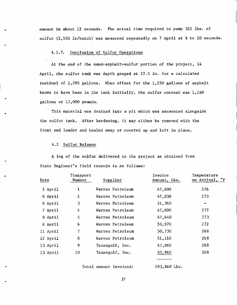
4.1.7~ Conclusion of Sulfur Operations
At the end of the sand-asphalt-sulfur portion of the project, 14
April, the sulfur tank was depth gauged at 22.5 in. for a calculated
residual of 2,290 gallons. When offset for the 1,150 gallons of asphalt
known to have been in the tank initially, the sulfur content was 1,140
gallons or 17,000 pounds.
This material was drained into a pit which was excavated alongside
the sulfur tank. After hardening, it may either be removed with the
front end loader and hauled away or covered up and left in place.
4.2 Sulfur Balance
A log of the sulfur delivered to the project as obtained from
State Engineer's field records is as follows:
• Transport Invoice Temperature Date Number Supplier Amount, Lbs. on Arrival, OF
5 April 1 Warren Petroleum 47,800 276
6 April 2 Warren Petroleum 47,830 273
6 April 3 Warren Petroleum 51,360
7 April 4 Warren Petroleum 47,600 272
8 April 5 Warren Petroleum 47,640 273
8 April 6 Warren Petroleum 50,970 272
11 April 7 Warren Petroleum 50,730 268
12 April 8 Warren Petroleum 51,110 268
13 April 9 Texasgulf, Inc. 47,860 268
13 April 10 Texasgulf, Inc. 50,960 268
Total amount invoiced: 493,860 Lbs.
37
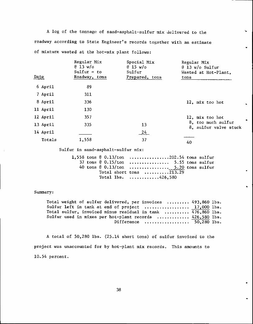
A log of the tonnage of sand-asphalt-sulfur mix delivered to the
roadway according to State Engineer's records together with an estimate
of mixture wasted at the hot-mix plant follows:
Regular Mix @ 13 w/o Sulfur - to
Date Roadway, tons
6 April 89
7 April 311
8 April 336
11 April 130
12 April 357
13 April 335
14 April
Totals 1,558
Special Mix @ 15 w/o Sulfur Prepared, tons
13
24
37
Regular Mix @ 13 w/o Sulfur Wasted at Hot-Plant, tons
12, mix too hot
12, mix too hot 8, too much sulfur 8, sulfur valve stuck
40
Sulfur in sand-asphalt-sulfur mix:
1,558 tons@ 0.13/ton ..•••.••••.•..•. 202.54 tons sulfur 37 tons@ 0.15/ton ••....••.•••••.. 5.55 tons sulfur 40 tons@ 0.13/ton ••.•••••.•••...• 5.20 tons sulfur
Total short tons ••.••.•... 213.29 Total lbs •.••.•••••••• 426,580
Summary:
Total weight of sulfur delivered, per invoices ••••••••. Sulfur left in tank at end of project •••••....••.•..•.. Total sulfur, invoiced minus residual in tank ••.•••••.. Sulfur used in mixes per hot-plant records ...••....••••
Difference •••••.••..•..••.•.
493,860 lbs. 172000 lbs.
476,860 lbs. 4262580 lbs. 50,280 lbs.
A total of 50,280 lbs. (25.14 short tons) of sulfur invoiced to the
project was unaccounted for by hot-plant mix records. This amounts to
10.54 percent.
38
..
•
•
4.3 Summary of Sulfur Handling
It was the sense of the contractors, engineers and visitors who
observed the construction operations that sulfur handling was a safe
practical construction operation.
4.4 Subgrade - 8" Lime Treated Soil
The 8" lime-treated soil subgrade for all test items was constructed
according to plans. In order to preserve the grade lines during construction
traffic, the subgrade was covered with several inches of F. B. (flexible
base) caliche. This cover was removed before placement of the pavement
mixtures and the exposed surface was tacked with emulsified asphalt; type
EA-llM diluted with several volumes of water. The tack was entirely
inadequate, effecting little or no bond of the paving mixture to the subbase.
There were some irregularitites in the subgrade profile. One was
located in the 10-inch sand-asphalt-sulfur section near station 1988
where the subgrade was several inches low •
The subgrade was swept with a power broom each day, as required,
before placing the pavement mixture to remove all loose material.
4.5 Preparation and Placement of the Sand-Asphalt-Sulfur Mix
Construction of the sand-asphalt-sulfur pavement was not a smooth
operation. Some pavement layers, one lane wide and hundreds of feet
in length, were placed true to line and grade and without noticable
imperfections. Some segments were ragged with widespread imperfections
of checks and tears, some skillfully patched and some not. There were
two general types of tearing and combinations of the two; one possibly
due to an excess of No. 50 to No. 100 mesh sand in the mixture, the
39
other caused by lumps of cold material passing under the screed. In
some stretches, the grade was undulating caused by a "galloping screed".
Two small segments the first 2-inch layer, right lane of the 4-inch
section, station 1997/60 to 1998/20 and the 2-inch layer, third lift,
left land of the 10-inch section station 1985/00 to 1985/50 were rejected
by the engineers and removed with a blade grader.
Good and poor pavement stretches were placed intermittently
throughout the project. At the same time, it is a desirable characteristic
of the soft (7-inch slump) hot sand-asphalt-sulfur mixture that it is
squeezed under the paver screed and into the surface imperfections of
the underlying layer.
There was considerable speculation among the engineers and consultants
as to the cause or causes of the construction problems. Some of these
are examined as follows:
4. 5 .1. Mixing
Hot-plant mixing was widely judged from visual inspection to be
non-uniform. The non-uniformity was manifested by color and texture
differences seen at the paver. Usually the dividing line was at or
near the center of the paver as the mixture passed through the hopper
suggesting that proportioning and/or mixing were different at opposite
ends of the pug-mill.
Mixing time, in general, followed the specifications which called for
5 seconds dry mixing, 20 seconds sand-asphalt mixing and 25 seconds
sand-asphalt-sulfur mixing. Total hatching time were checked on
different days and showed a range to 60 to 80 seconds.
Some adjustments were made in the spray bar in the pug-mill. Nozzles
40
•
•
..
•
•
•
were closed on one end where the mix visually appeared to be the richest
in binder. The color and texture differences then seemed to shift from
that side to the other side accordingly, but were not eliminated.
There is little, if anything, to suggest a maldistribution of
asphalt in the mixture from studying the field laboratory determinations.
Sulfur distribution may be suspect from studies of the field tests
but so, also, was the precision of the test methods used. See Quality
Control, Section 5.0 page 81.
Some material was observed to ride atop the paddles when the batch
weights were initially set to total 3,000 lbs. This was stopped by
reducing the batch sizes first to 2,500 lbs. and then to 2,000 lbs.
There was some contention that mix temperatures contributed to
variability in mix consistencies. There is little, if any, support
for this, except for a few loads, to be found in the field measurements
of temperatures at the hot-plant and checked in the field. See Quality
Control, Section 5.0 page 81 •
There was a build-up of hard materials in the pug-mill especially
during the first two days. On 7 April the pug-mill was cleaned by
chopping out the hard mix, mixing with clean sand and flushing with
fuel oil. Adjustments were made in the heating and insulation of the
pug-mill but the problem did not disappear.
The one source of known wide variability throughout the project
was in the sand gradings, a variability which in conventional asphalt
concrete pavement construction can produce "lean" and "rich", "tough"
and "workable" mixtures and with obvious color and texture differences .
41
In summary, hot-mix plant mixing efficiency was suspect and as it
turned out there was a basic mechanical problem. This may very well be
an explanation for some of the aggregate grading variations reported.
Purportedly, the paddle arrangement in the pug-mill was changed prior
to receiving the coventional asphalt concrete mixture to push the material
into what is known in the trade as a "figure-eight" or a 3-dimensional
figure-eight. No nonuniform mixing was encountered following this
operation.
4.5.2. Hauling
The four haul trucks with the special heated beds were used to
transport the sand-asphalt-sulfur mixture from the hot-plant to the
roadway. The center of the test project was about 3,500 feet from the
hot-plant but the circuitous route elected extended the haul distance
to about 1 1/2 miles. Excellent weather prevailed throughout the
project.
Only two mechanical problems were noted in the truck operation. The
transmission on one truck malfunctioned leaving only one forward speed.
On another truck a fire broke out in the wiring system, battery to
burner on the bed. It was extinguished without appreciable damage.
Propane bottles, two per truck, were filled as required by drivers from
storage at the hot-plant site. A Shell Canada engineer tended the trucks
at all times and assisted with the burners and cleaning of the beds.
Before each shift each truck bed was thoroughly cleaned and coated
inside with fuel oil. During use there was some formation of cold lumps
of materials in all truck bodies usually more pronounced in the front
bottom corners and about the rear end gate. It was routine throughout
....
•.
•
•
42 ~
the project for the drivers to return the empty trucks to a waste pile
near the hot-plant, raise the bed and remove the hard attached mix by
chopping and scraping. In at least one instance neat sulfur (i.e.
unassociated with sand and asphalt), was evident at the metal to
mixture interface.
4.5.3. Placing
There were two intermittent problems at the paver; tearing under
the screed and "galloping of the screed" to create transverse waves.
The tearing was of two types and combinations of the two; tearing
apparently caused by a lack of cohesion in the mixture possibly attributable
to an excess of one-size particles of sand and the other by lumps of
cold mix dragging under the screed.
When the temperature of the sand-asphalt-sulfur mixture cools much
below the melting point of sulfur (ca. 250F), the mixture becomes stiff.
It is therefore basic that the material not be permitted to cool below
250F anywhere in-route from the hot-mix plant to the roadway. This
requirement is reflected in the project specifications which states in
part: "The entire system, hopper to screed, shall be of such design and
operation as to assure uniform flow of the mixture and prevent material
from collecting and cooling in the spreader".
Continuous operation of the paver was impracticable. Plant
production rarely exceeded 50 tons per hour. For continuous operation,
the paver would have to be slowed to about 6 ft./min. on the 2-inch layer
from a normal speed of 20 ft./min. or more. Two procedures were tried.
In one, the four haul trucks were loaded and grouped at the paver. Paving
43
was continuous until the four loads were placed at which point the paver
was run-out. The crew was then required to clean and scrape the hopper
to remove solidified material. In the other, the paver speed was slowed
to match hot-plant production. The latter was preferred by the crew
since it eliminated the need for periodic clean-up of the paver. However,
build up of solid material in the hopper was produced in this method as
well and require cleaning and scraping for removal.
A string line on one side of the paver was usually used as a grade
reference for the initial layers in each test item. A skid reference
unit (joint matcher) was used, generally, on subsequent paver courses
although from time to time changes were made from the one skid reference
unit to a travelling string line.
There were stretches where transverse waves were left in the pave
ment after passage of the screed. The automatic screed control may have
malfunctioned. This was a recurrent problem possibly attributable to
variability in the consistency of the mixture which precluded a fixed
attack angle for the screed.
4.5.4. Summary of Mixing and Placing
From field observations and inspection of the field laboratory
test data, the quality of the pavement, as placed, seems to relate to
the time of day and the clean-up of all equipment. In general
the best quality pavement was that placed earliest in the day and
following the previous night equipment clean-up. Two examples can be
cited. On 7 April paving began at 9:15am. From 2:25 to 3:20pm., the
first 3-inch layer, right lane, 7-inch section, station 1990 to 1995
44
was paved with quality of the pavement decreasing with time. The paver
then moved to station 1990 for paving back to station 1985. The second
3-inch layer in the right lane of the 10-inch section was a near continuous
mass of transverse waves, checks and tears and poor patching. A complete
clean-up of all equipment was made that evening. On 8 April paving
started at station 1985, left lane, second 3-inch layer at 10:27 am.
The next 6 or 8 hundred lineal feet, reaching into the 7-inch section
was placed with near perfection. Also on 12 April, following the
rejection of some pavement placed on previous day and general clean-up
that night, near perfect pavement was placed for hundreds of lineal
feet of the first 2-inch layer, right lane ahead of station 1985. There
were other examples which tend to support this hypothesis. The advantage
of the learning process should not be overlooked as an input to an
important operation.
It was the sense of the engineers and crews that the mixtures
should be uniform and perhaps the automatic controls on the paver
should have been fine tuned to eliminate the waves in the surface.
Also, the formation of lumps must be eliminated or substantially
reduced to relieve the burdens of continuous clean-up of the pug
mill, the trucks and the paver.
At the conclusion of the planned project some 35 tons of S-A-S was
prepared and placed using local field sand as the only aggregate.
Observations by SDHPT personnel in the field laboratory and on the
placing site indicated that this mixture produces a pavement equal in
quality to that consisting of the blended sands. This was no surprise
to many of those who observed the operation, since it was consistent
45
with TTl's laboratory findings. In fact, virtually all of TTl's effort
from the outset of this program has been associated with unblended,
poorly-graded, beach sands. The major obstacle to the utilization of
significantly higher fractions of local sands on this project was the
current state of development of the paver. Paver modification utilizing
another mode of screed motion is now under study by Shell which could
provide a solution to this problem.
4.5.5. Joints
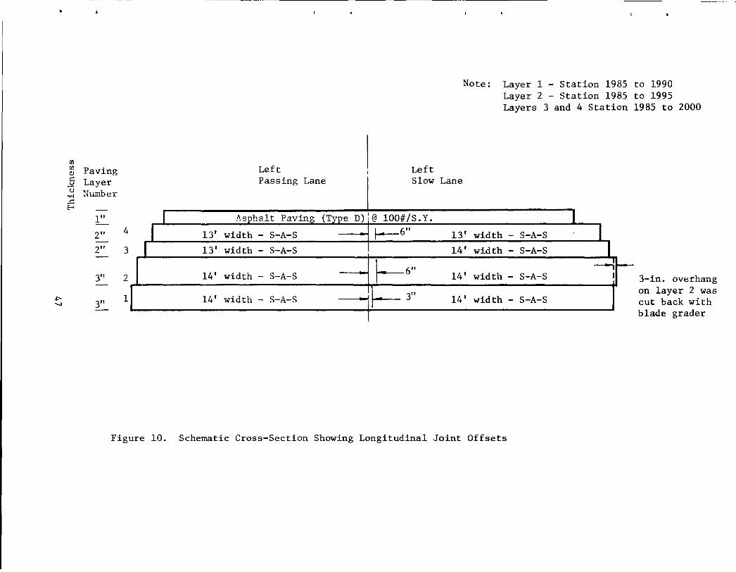
Paving widths were 14 ft. and 13 ft. as shown in Figure 10 with the
centerline joints offset either 3 or 6-inches. In all cases where a
layer abutted another layer, the face against which the layer was placed
was first painted with a heavy coat of emulsified asphalt, Type EA-llM,
applied with a hand hose attached to the asphalt distributor.
Transverse joints were constructed where operations were markedly
delayed. The leading edge of the layer was cut back to a near straight
line with a vertical face. The surplus material was removed by trans
verse blading with a road grader. The vertical face of the joint was
given a heavy coat of emulsion also applied from the asphalt distributor.
4.5.6. Patching
Patching, not always done well, consisted of tamping the small checks
and tears with the flat side of a lute or shovel to close the surface
and provide a continuous although thinner layer over the spot. Larger
imperfections were filled with hot mixture from the hopper or from in
front of the screed and tamped to grade.
46
Cll Cll (\)
] tJ
..,.;
.c f-1
~ -....!
._
Paving Layer Number
1" I 2" 4 I -2" 3 I -
3" 2 -3" 1 I
Left Left
Note: Layer 1 - Station 1985 to 1990 Layer 2 - Station 1985 to 1995 Layers 3 and 4 Station 1985 to 2000
Passing Lane Slow Lane
Asphalt Paving (Type D):@ 100#/S.Y.
13' width - S-A-S f--6"
13' width - S-A-S
14' width - S-A-S ~6" 14' width - S-A-S !1 3"
~ I
I 13' width - S-A-S
14' width - S-A-S
14' width - S-A-S
14' width - S-A-S
I I
--I I 3-in. overhang
on layer 2 was cut back with blade grader
Figure 10. Schematic Cross-Section Showing Longitudinal Joint Offsets
4.5.7. Smoothing the Pavement Surfaces
In areas such as that described above, and in particular the second
3-inch layer lift in the right lane of the 10-inch section placed 7
April tight blading with a road grader was used in an attempt to improve
surface smoothness. The sand-asphalt-sulfur at or less than one day
old "cut like cheese". After several days, it was too hard. The blade
would grind over the surface producing sparks and some smoke and an odor
of sulfur. After completion of the sand-asphalt-sulfur test items and
before placing the 100· lbs/per S.Y. surfacing, fine graded asphalt hot
mix was bladed over the roughest areas in preparation for the final
riding surface.
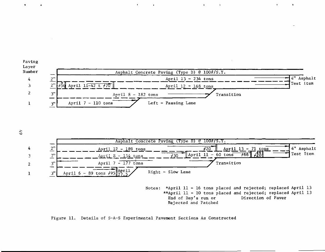
4.5.8. Log of Field Construction- Sand-Asphalt-Sulfur Test Items
Details of S-A-S experimental pavement construction showing tons of
sand-asphalt-sulfur pavement mixture placed by dates, quantities,
pavement layer, traffic lane and engineer station, is depicted in Figure
11.
A log of Field Construction is contained in Appendix A. It includes
by date and station, the load number, section, layer and layer thickness
where placed together with time and mix temperature as recorded by the
State Engineers.
4.5.9. Weather
The two weather services closest to the construction site were
located at Brownsville and at Corpus Christi. The following weather
information was provided by the U.S. Weather Service, Corpus Christi,
48
..,... \0
Paving Layer Number
4
3
2
1
4
3
2
1
~
Asphalt Concrete Paving (Type D) @ 100#/S.Y.
2" ~r, ____ -:y-_____ __!!pril .... !_3_:_234 ~I!!_ ______ ----::t 4" Asphalt
2" f5~~pril_2l-~~f70 JL ----- _Apri.~ .. _1L..:..1_6Lt~s Test Item
3" April 8 - 182 tons Transition - ------ -.:::::...::=-::;::.r--~-:---:-----3" April 7 - 110 tons Left - Passing Lane
Asphalt-Concrete
2" _____ _!pril_lL.:...!§U<2!!..s_____ __!20-JL_Apr!l....ld._- 71 to!l2_ _ _: 4" Asphalt _____ Aprll.L-...1.S.Lt.£UL __ _ iJO -Ep~l~l_:- 60 tons Test Item 2"
3" April 7 - 177 tons Transition -------- ~
3" . Right - Slow Lane
Notes: *April 11 - 16 tons placed **April 11 - 10 tons placed
End of Day's run or Rejected and Patched
and rejected; replaced April 13 and rejected; replaced April 13
Direction of Paver
Figure 11. Details of S-A-S Experimental Pavement Sections As Constructed
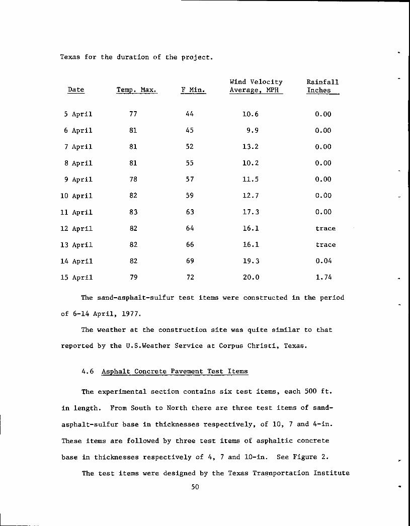
Texas for the duration of the project.
Wind Velocity Rainfall Date Temp. Max. F Min. Average, MPH Inches
5 April 77 44 10.6 0.00
6 April 81 45 9.9 0.00
7 April 81 52 13.2 0.00
8 April 81 55 10.2 0.00
9 April 78 57 11.5 0.00
10 April 82 59 12.7 0.00
11 April 83 63 17.3 0.00
12 April 82 64 16.1 trace
13 April 82 66 16.1 trace
14 April 82 69 19.3 0.04
15 April 79 72 20.0 1. 74
The sand-asphalt-sulfur test items were constructed in the period
of 6-14 April, 1977.
The weather at the construction site was quite similar to that
reported by the U.S.Weather Service at Corpus Christi, Texas.
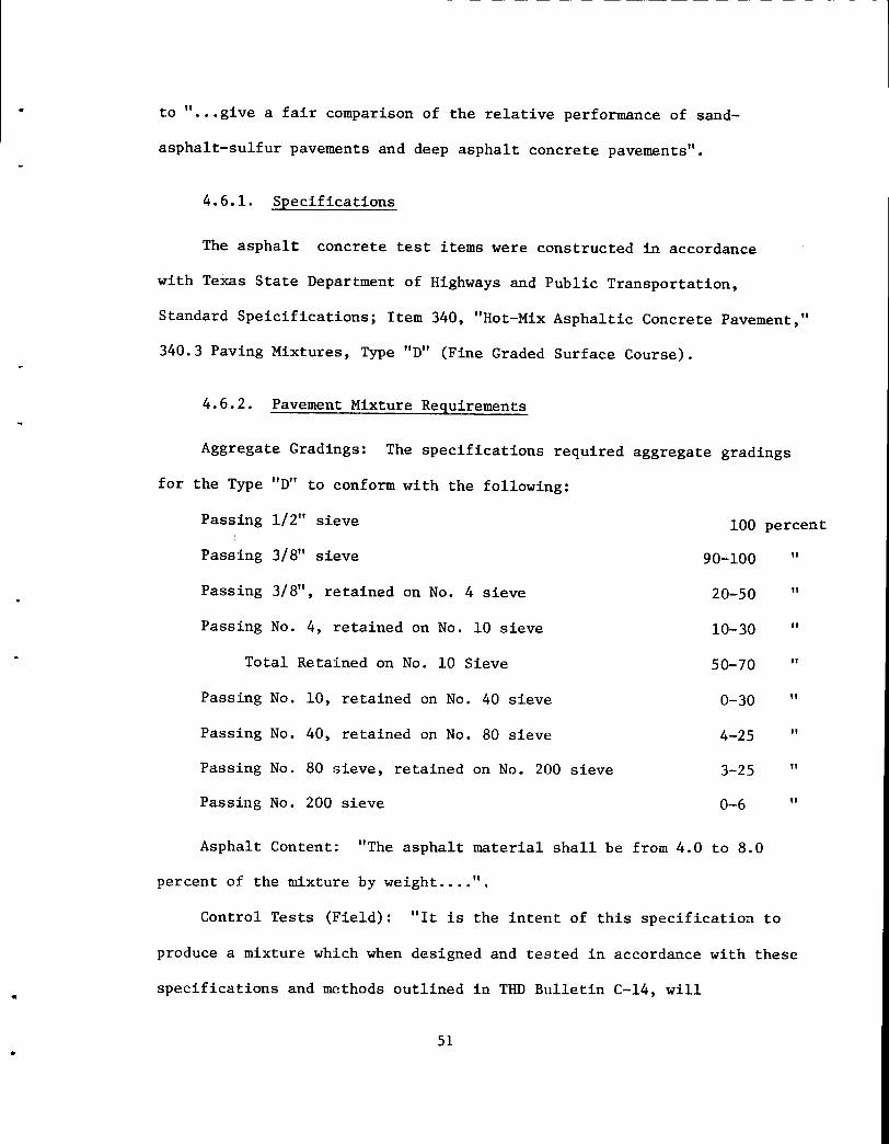
4.6 Asphalt Concrete Pavement Test Items
The experimental section contains six test items, each 500 ft.
in length. From South to North there are three test items of sand-
asphalt-sulfur base in thicknesses respectively, of 10, 7 and 4-in.
These items are followed by three test items of asphaltic concrete
base in thicknesses respectively of 4, 7 and 10-in. See Figure 2.
The test items were designed by the Texas Trasnportation Institute
50 ...
..
•
to " ••. give a fair comparison of the relative performance of sand
asphalt-sulfur pavements and deep asphalt concrete pavements".
4.6.1. Specifications
The asphalt concrete test items were constructed in accordance
with Texas State Department of Highways and Public Transportation,
Standard Speicifications; Item 340, "Hot-Mix Asphaltic Concrete Pavement,"
340.3 Paving Mixtures, Type "D" (Fine Graded Surface Course).
4.6.2. Pavement Mixture Requirements
Aggregate Gradings: The specifications required aggregate gradings
for the Type "D" to conform with the following:
Passing 1/2" sieve 100
Passing 3/8" sieve 90-100
Passing 3/ 8", retained on No. 4 sieve 20-50
Passing No. 4, retained on No. 10 sieve 10-30
Total Retained on No. 10 Sieve 50-70
Passing No. 10, retained on No. 40 sieve 0-30
Passing No. 40, retained on No. 80 sieve 4-25
Passing No. 80 sieve, retained on No. 200 sieve 3-25
Passing No. 200 sieve 0-6
Asphalt Content: "The asphalt material shall be from 4.0 to 8.0
percent of the mixture by weight .... ".
percent
II
II
II
II
II
II
II
II
Control Tests (Field): "It is the intent of this specification to
produce a mixture which when designed and tested in accordance with these
specifications and methods outlined in THD Bulletin C-14, will
51
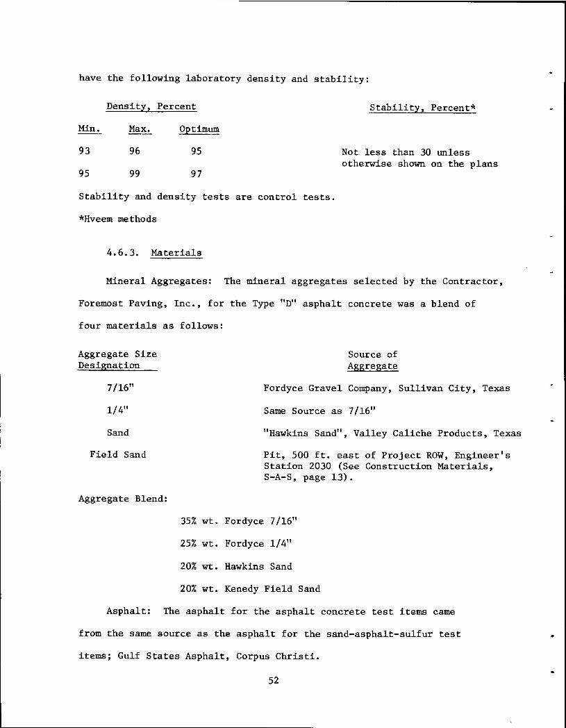
have the following laboratory density and stability:
Density, Percent Stability, Percent*
Min. Max.
93 96
95 99
Optimum
95
97
Not less than 30 unless otherwise shown on the plans
Stability and density tests are control tests.
*Hveem methods
4.6.3. Materials
Mineral Aggregates: The mineral aggregates selected by the Contractor,
Foremost Paving, Inc., for the Type "D11 asphalt concrete was a blend of
four materials as follows:
Aggregate Size Designation
7/16"
1/4"
Sand
Field Sand
Aggregate Blend:
Source of Aggregate
Fordyce Gravel Company, Sullivan City, Texas
Same Source as 7/16"
"Hawkins Sand11, Valley Caliche Products, Texas
Pit, 500 ft. east of Project ROW, Engineer's Station 2030 (See Construction Materials, S-A-S, page 13).
35% wt. Fordyce 7/16"
25% wt. Fordyce 1/4"
20% wt. Hawkins Sand
20% wt. Kenedy Field Sand
Asphalt: The asphalt for the asphalt concrete test items came
from the same source as the asphalt for the sand-asphalt-sulfur test
items; Gulf States Asphalt, Corpus Christi.
52
..
•
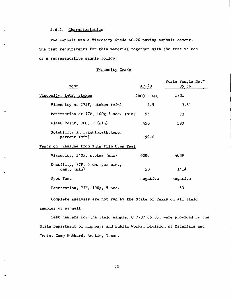
4.6.4. Characteristics
The asphalt was a Viscosity Grade AC-20 paving asphalt cement.
The test requirements for this material together with the test values
of a representative sample follow:
Viscosity Grade
Test
Viscosity, 140F, stokes
Viscosity at 275F, stokes (min)
Penetration at 77F, lOOg 5 sec. (min)
Flash Point, COC, F (min)
Solubility in Trichlorethylene, percent (min)
Tests on Residue from Thin Film Oven Test
Viscosity, 140F, stokes (max)
Ductility, 77F, 5 em. per min., ems., (min)
Spot Test
Penetration, 77F, lOOg, 5 sec.
State Sample No.* AC-20 05 56
2000 + 400 1731
2.5 3.61
55 73
450 590
99.0
6000 4039
50 141-f
negative negative
50
Complete analyses are not run by the State of Texas on all field
samples of asphalt.
Test numbers for the field sample, C 7737 05 85, were provided by the
State Department of Highways and Public Works, Division of Materials and
Tests, Camp Hubbard, Austin, Texas •
53
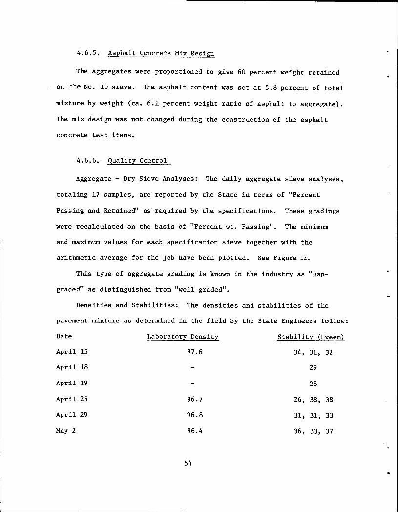
4.6.5. Asphalt Concrete Mix Design
The aggregates were proportioned to give 60 percent weight retained
on the No. 10 sieve. The asphalt content was set at 5.8 percent of total
mixture by weight (ca. 6.1 percent weight ratio of asphalt to aggregate).
The mix design was not changed during the construction of the asphalt
concrete test items.
4.6.6. Quality Control
Aggregate - Dry Sieve Analyses: The daily aggregate sieve analyses,
totaling 17 samples, are reported by the State in terms of "Percent
Passing and Retained" as required by the specifications. These gradings
were recalculated on the basis of "Percent wt. Passing". The minimum
and maximum values for each specification sieve together with the
arithmetic average for the job have been plotted. See Figure 12.
This type of aggregate grading is known in the industry as "gap
graded" as distinguished from "well graded".
Densities and Stabilities: The densities and stabilities of the
pavement mixture as determined in the field by the State Engineers follow:
Date
April
April
April
April
April
May2
15
18
19
25
29
Laboratory Density
97.6
96.7
96.8
96.4
54
Stability (Hveem)
34, 31, 32
29
28
26, 38, 38
31, 31, 33
36, 33, 37
..
•
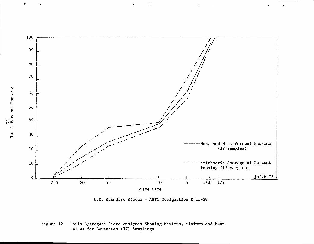
• •
1:: I r
8o L
70 l ~ I ·rl 60 (/) (/)
111 p..
-1-.J ~ Q) (.)
1-1 I.JlQ) I.Jlp..
.-(
111 -1-.J 0 ~
50
40
30
20
10 ·-
/
//
/
W / /
/
~---
-------Max. and Min. Percent Passing (17 samples)
----Arithmetic Average of Percent Passing (17 samples) %/'
0 I I I t _j_ joi/6-77 200 80 40 10 4 3/8 1/2
Sieve Size
U.S. Standard Sieves - ASTM Designation E 11-39
Figure 12. Daily Aggregate Sieve Analyses Showing Maximum, Minimum and Mean Values for Seventeen (17) Samplings
•
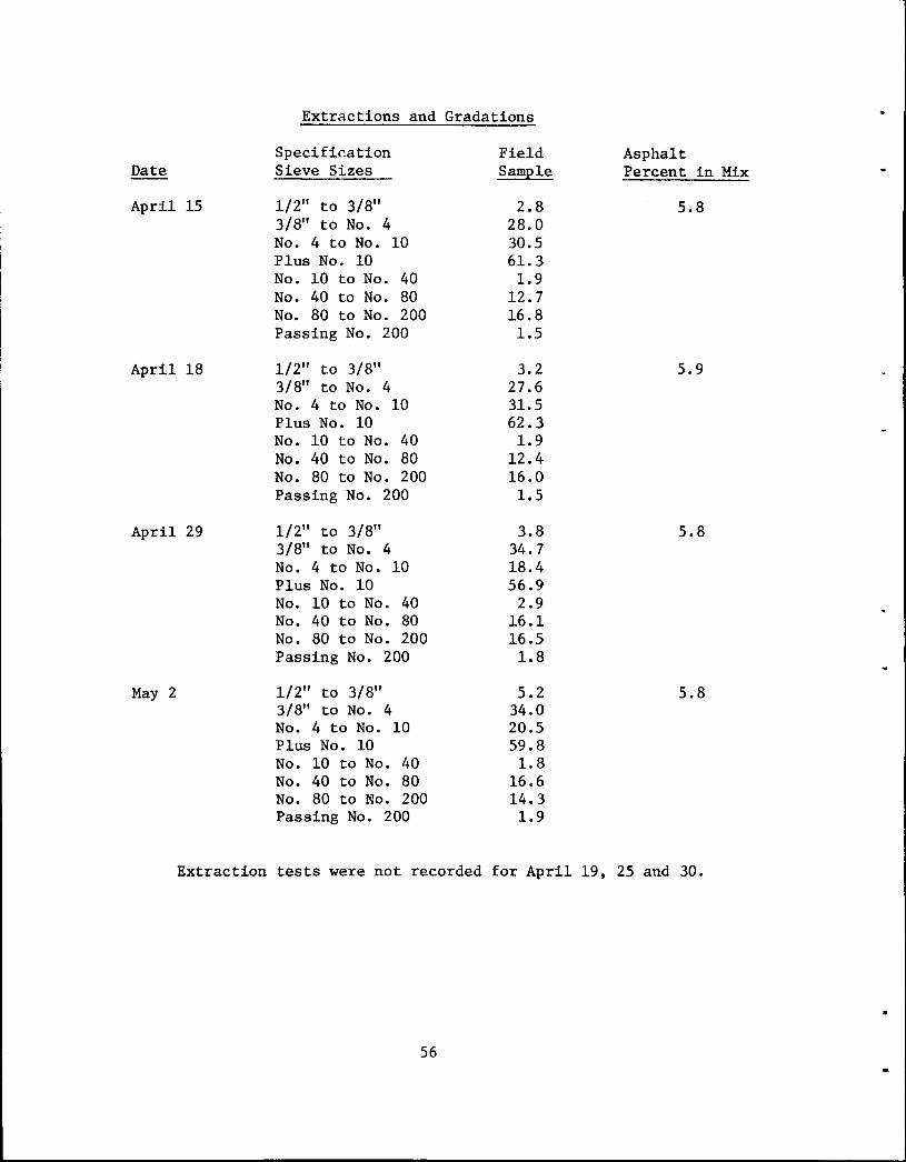
Date
April 15
April 18
April 29
May 2
Extractions and Gradations
Specification Sieve Sizes
1/2" to 3/8" 3/8" to No. 4 No. 4 to No. 10 Plus No. 10 No. 10 to No. 40 No. 40 to No. 80 No. 80 to No. 200 Passing No. 200
1/2" to 3/8" 3/8" to No. 4 No. 4 to No. 10 Plus No. 10 No. 10 to No. 40 No. 40 to No. 80 No. 80 to No. 200 Passing No. 200
1/2" to 3/8" 3/8" to No. 4 No. 4 to No. 10 Plus No. 10 No. 10 to No. 40 No. 40 to No. 80 No. 80 to No. 200 Passing No. 200
1/2" to 3/8" 3/8" to No. 4 No. 4 to No. 10 Plus No. 10 No. 10 to No. 40 No. 40 to No. 80 No. 80 to No. 200 Passing No. 200
Field Sample
2.8 28.0 30.5 61.3 1.9
12.7 16.8 1.5
3.2 27.6 31.5 62.3 1.9
12.4 16.0 1.5
3.8 34.7 18.4 56.9
2.9 16.1 16.5 1.8
5.2 34.0 20.5 59.8 1.8
16.6 14.3 1.9
Asphalt Percent in Mix
5.8
5.9
5.8
5.8
Extraction tests were not recorded for April 19, 25 and 30.
56
•
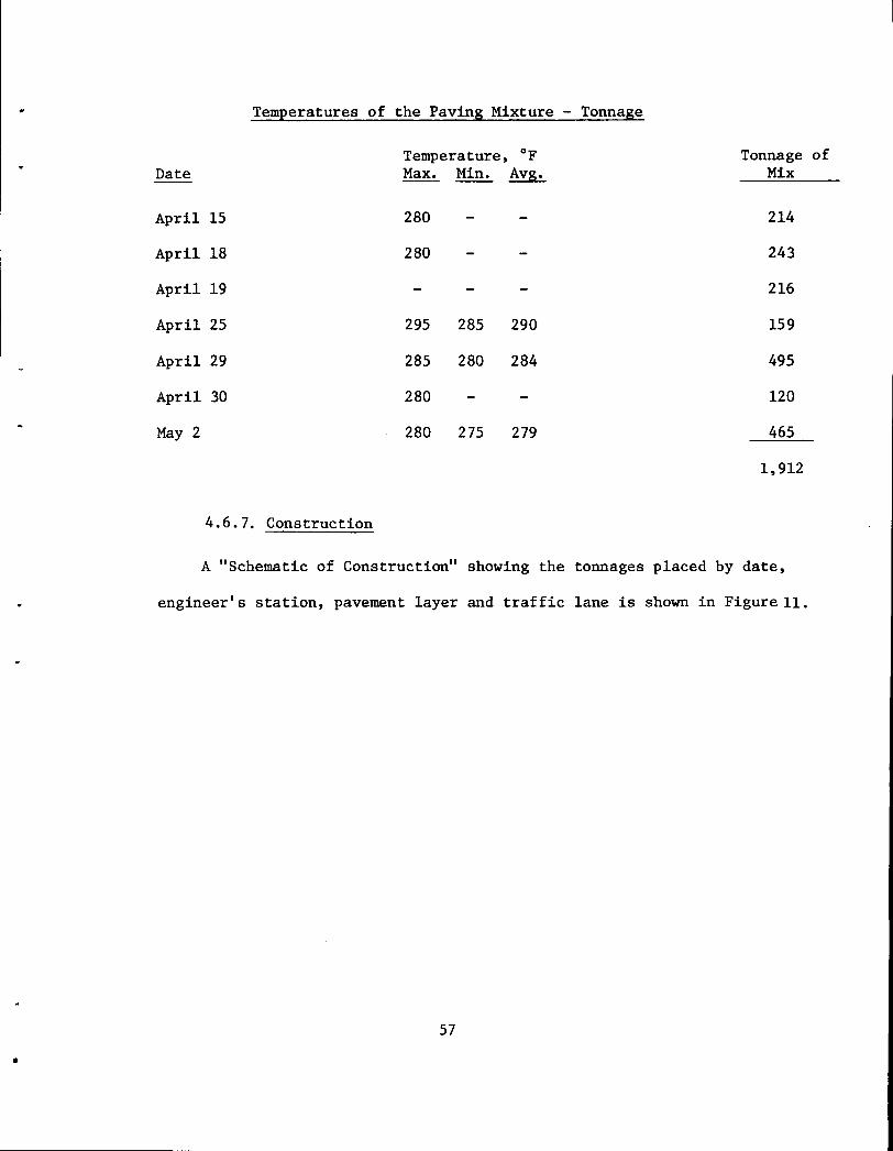
Temperatures of the Paving Mixture - Tonnage
Temperature, °F Ton~age of Date Max. Min. Avg. Mix
April 15 280 214
April 18 280 243
April 19 216
April 25 295 285 290 159
April 29 285 280 284 495
April 30 280 120
May2 280 275 279 465
1,912
4.6.7. Construction
A "Schematic of Construction" showing the tonnages placed by date,
engineer's station, pavement layer and traffic lane is shown in Figure 11.
57
•
4.7 Evolved Gas Analysis
General: Throughout the development of the sulfur/asphalt concept
one of the major concerns of the industry has been the potential hazards
created at the construction site due to the evolution of toxic gases
(H2s and so
2) and particulate sulfur. Over the years Shell Canada has
monitored these pollutants both in the laboratory as well as in conjunction
with their Thermopaver field trials. As yet, none of their data has been
reported in the open literature. However, Shell has stated that as long
as the temperature of the mix is maintained below 300°F the concentrations
of H2s and so
2 produced are well below the maximum allowable concentrations
(MAC) as suggested by the American Conference of Governmental Industrial
* Hygienists (ACGIH) [1] . Similar studies at TTl and the Bureau of Mines
support this claim [2, 3]. Because of its importance to the general
acceptability of the sand-asphalt-sulfur concept an emissions monitoring
activity was incorporated into this project.
4.7.1. Equipment
The responsibility for collecting these data was shared by three
agencies; TTl, The Bureau of Mines and The Texas Air Control Board (TACB).
The latter is charged with the responsibility of assessing the environ-
mental impact of various types of industrial pollutants for the state of
Texas. A meeting was held at the TACB facility in Austin, Texas on
November 28, 1976. In addition to the three participating agencies
mentioned above, Mr. William Gaw of Shell Canada was also present. A
breakdown of the responsibilities and the specific monitoring equipment
* Numbers in brackets are references which are listed on page at the end of this section.
58
•
which was to be furnished by each agency was resolved at that meeting and
is shown in Table II.
Although TACB had the responsibility for monitoring particulate sulfur
these data were not generated on this project. Except for specific monitoring
equipment used, all other responsibilities as shown in Table II were ful
filled. The evolved gas measurements were taken during the construction
period 5 - 7 April, 1977 which corresponds to the dates duting which the
sand-asphalt-sulfur pavement was being placed. TACB data were obtained
using a mobile sampling van (see Figure 13) equipped with a Meloy SA1655
total sulfur analyzer, a Houston Atlas H2s tape sampler and an Interscan
Model 1176 H2s analyzer. An Omniscible Model 5213-15 dual pen chart recorder
was used to record signals from the Meloy and Interscan instruments and a
Weather Measure Corporation electronic polyrecorder Model EPR - 200A was
used to record signals from the Houston Atlas unit.
The mobile van moved about the various sampling sites at the discretion
of TACB personnel. Specifically, measurements were taken at the following
locations: sulfur storage tank, hot-mix plant mixing chamber and the paver
hopper and auger. Additional measurements were taken downwind of the plant
and paver so as to establish dissipation factors. Locations of the various
sampling sites monitored by TACB are shown in Figures 14 to 16.
Except for downwind samplings, most of the emissions readings generated
by TACB were considered to be source type data; that is measurements were
taken directly over the mixture. This was accomplished using a Midget
Impinger Gaseous Air Sampling Train (MIGAST). MICAST samples were taken
using Bendix Telematic 150A automatic air samplers with a cadmium hydroxide
absorbing solution .. Samples were collected with a 5-ft. length probe of
3/8 in. O.D. stainless steel tubing. Gases were sucked back to the analyzer
59
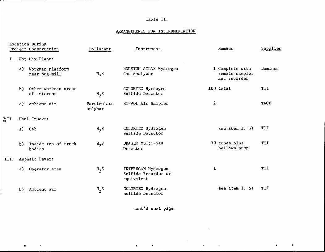
Table II.
ARRANGEMENTS FOR INSTRUMENTATION
Location During Project Construction Pollutant Instrument Number Supplier
I. Hot-Mix Plant:
a) Workman platform HOUSTON ATLAS Hydrogen 1 Complete with Bumines near pug-mill H2S Gas Analyzer remote sampler
and recorder
b) Other workman areas COLORTEC Hyrdogen 100 total TTl of interest H2S Sulfide Detector
c) Ambient air Particulate HI-VOL Air Sampler 2 TACB sulphur
~II. Haul Trucks:
a) Cab H2S COLORTEC Hydrogen see item I. b) TTl Sulfide Detector
b) Inside top of truck H2S DRAGER Multi-Gas 50 tubes plus TTl bodies Detector bellows pump
III. Asphalt Paver:
a) Operator area H2S INTERSCAN Hydrogen 1 TTl Sulfide Recorder or equivalent
b) Ambient air H2S COLORTEC Hydrogen see item I. b) TTl sulfide Detector
cont'd next page
..
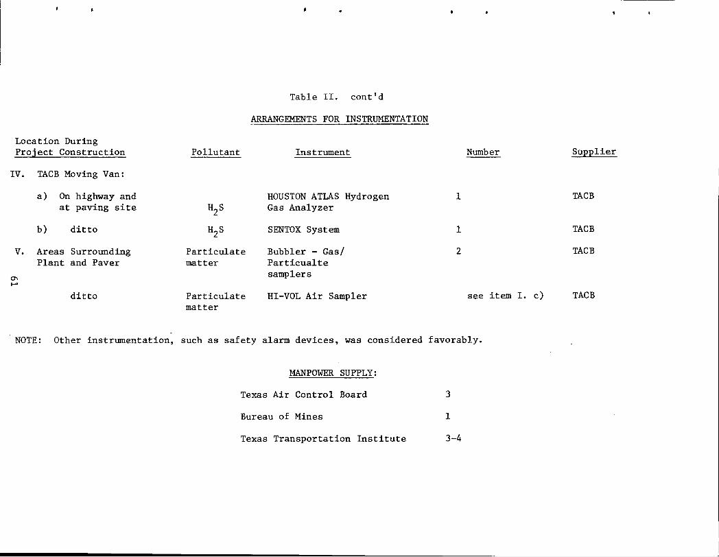
Location During Project Construction
IV. TACB Moving Van:
a) On highway and at paving site
b) ditto
V. Areas Surrounding Plant and Paver
~ ..... ditto
Pollutant
H2S
H2S
Particulate matter
Particulate matter
•
Table II. cont'd
ARRANGEMENTS FOR INSTRUMENTATION
Instrument Number
HOUSTON ATLAS Hydrogen 1 Gas Analyzer
SENTOX System 1
Bubbler - Gas/ 2 Particualte samplers
HI-VOL Air Sampler see item I. c)
NOTE: Other instrumentation, such as safety alarm devices, was considered favorably.
MANPOWER SUPPLY:
Texas Air Control Board 3
Bureau of Mines 1
Texas Transportation Institute 3-4
Supplier
TACB
TACB
TACB
TACB
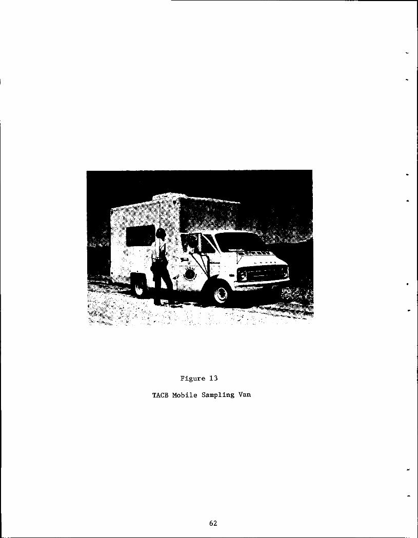
•
•
Figure 13
TACB Mobile Sampling Van
62
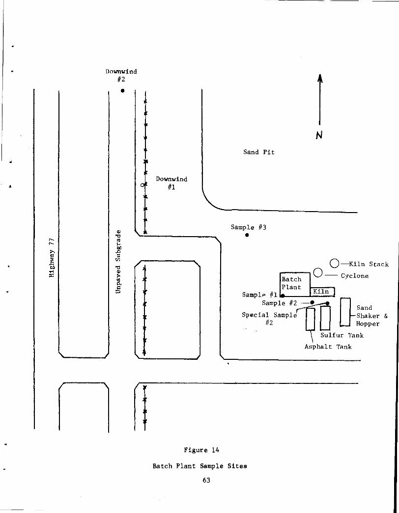
..
,..._ ,..._
:>. t1S
.E eo -M ::t:
Downwind 112
•
Cll "'0
t1S ,... bO ~ ::l
t/)
"'0 Cll > t1S p.. ~ t:l
Downwind Ill
Figure 14
Sand Pit
Sample 113
•
N
0---Kiln Stack
-----. 0 -- Cyclone Batch Plant
Samp lP ttl •'-~ _ __. .... K_i_l_n.-.~1
0-~~:~er &
Sample 112
Special Sample 1!2 Hopper
Asphalt Tank
Batch Plant Sample Sites
63
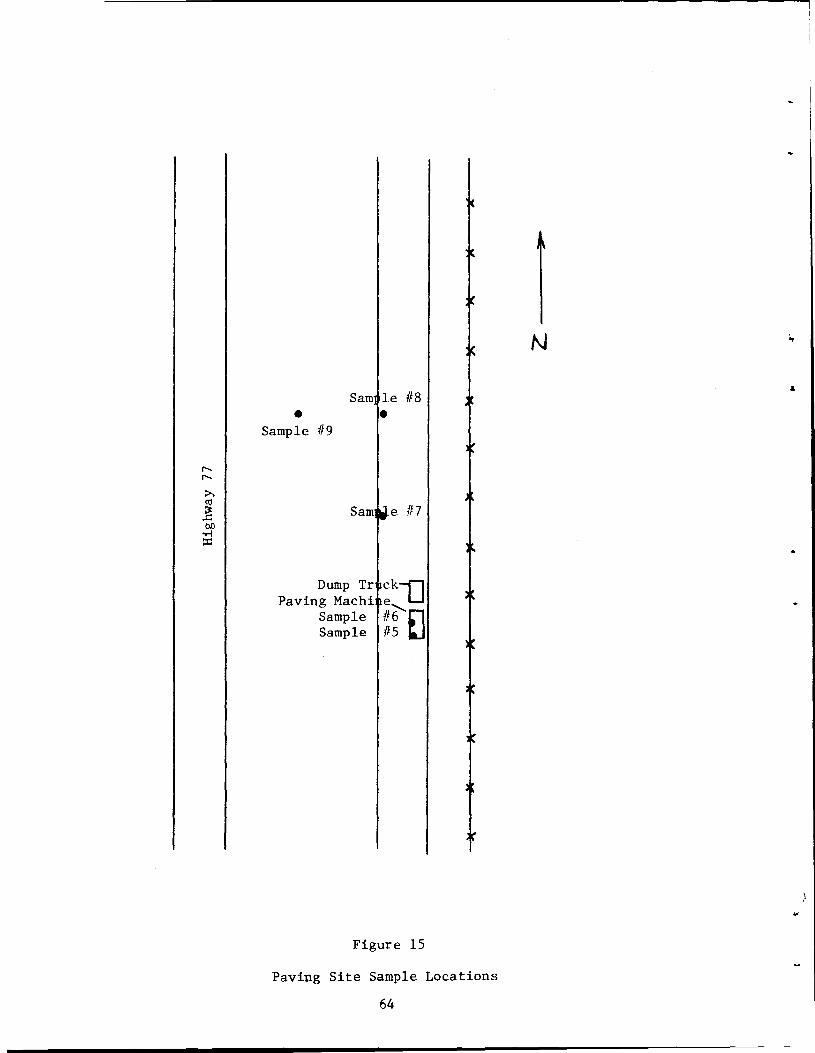
N ..
Sam le 118
• • Sample lt9
r-.. r-..
:>-.
~ ..c: Sam e 117 00
...-j
::I:: •
Dump Tr ~k1J Paving Machi Sample 116'-EJ Sample 115
Figure 15
Paving Site Sample Locations
64
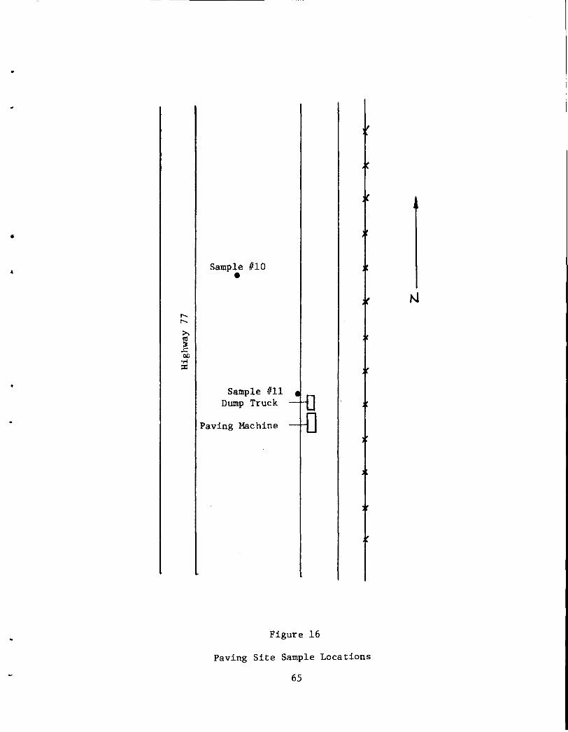
•
I
•
-----------------------------------------------------
Sample 1110 •
Sample fill Dump Truck
Paving Machine
Figure 16
Paving Site Sample Locations
65
through a 1/4 in. polyethylene tube by a Metal Bellows Company, Model MB-41
pump. Samples were collected by placing the probe tip at distances which
ranged from 1 to 12 inches from the surface of the material from which the
gases were being evolved. These distances are much less than that normally
occupied by personnel (normally 3 to 6 ft.) hence the designation "source
data" were assigned to these samplings. As a backup to the source data
collected by TACB, both TTl and The Bureau of Mines samplings were obtained
at locations more representative of those which might be expected to be
occupied by personnel.
One such area was on the platform of the hot-mix plant where the
various mix ingredients were introduced into the pug mill. Continuous samplings
over a 24-hour period were taken in the vicinity of the manually operated
feed controls at a height equal to nose level of the operator. Additional 24-
hour continuous samplings were taken at a point under the pug mill and just
over the dump bodies of the trucks. Both of these points were monitored using
a Houston Atlas Sampler of the type mentioned above. This unit was furnished
by The Bureau of Mines Metallurgy Research Laboratory of Boulder City, Nevada.
TTl personnel took samplings for both H2s and so2 using two types of
portable sensing instruments. A Metronics Model 721 "Rotorod" Gas Sampler
(Figure 17) which is designed for monitoring only H2
S emissions was used to
collect data in the vicinity of the plant, within the quality content testing
laboratory, inside the cab of hauling trucks, at the paver operator's seat,
alongside the paver at the hopper and at the auger and in the vicinity of
the sulfur storage tanks.
The Rotorod Gas Sampler spins a disc on which is mounted a lead acetate
treated pad. Upon exposure to H2s the pad changes color which can be compared
with 5 standards located around the perimeter of the treated pad. The color
66
•
•
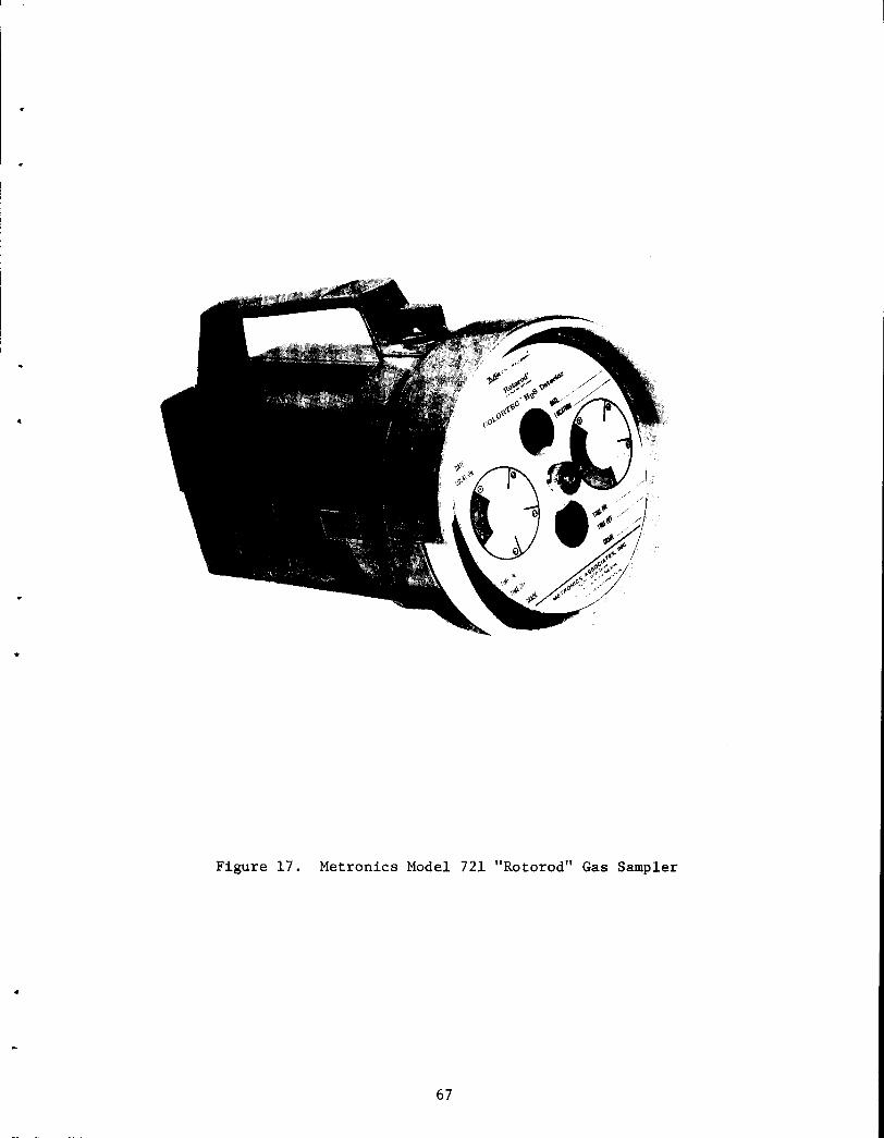
Figure 17. Metronics Model 721 "Rotorod" Gas Sampler
..
67
grade number of the stain produced on the pad and the duration of the sampling
time are then converted to H2s concentrations using the chart shown in Figure
18. Colortek cards as shown in Figure 19 were also used. These were mounted
on walls and other locations where sampling duration times were. greater than
30 minutes.
The other portable sampler employed was a Drager Tube Sampler with a
manually operated bellows. Appropriate callibrated tubes for monitoring
both H2s and so2 were used with this device.
Samplings were taken at essentially the same locations monitored by
the Metronics Rotorod Sampler. Drager tube measurements of H2s concentra
tions thus provided a back up to those taken with the Rotorod Sampler.
4.7.25 Hydrogen Sulfide
4.7.2.1. Relative Toxicity of H2S
Hydrogen Sulfide is known for its characteristic "rotten egg" odor.
Although this odor is noticeable at concentrations as low as 0.02 ppm [1],
odor is not a good indicator of concentration level. Hydrogen sulfide can
have a paralyzing effect on the sense of smell [2]. Therefore, high
concentrations of H2s can escape recognition.
The basis used for establishing the relative toxicity of emissions
data generated during this project were the relationships between H2s
concentrations and human effects as specified by ACGIH [1, 3]. These
relationships are shown below:
68
..
•
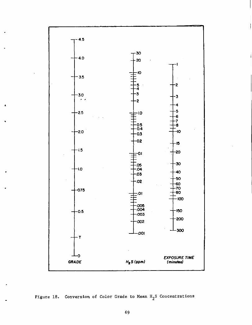
&
T
0 GRADE H1 S(ppm}
EXPOSURE TIME (minute•}
Figure 18. Conversion of Color Grade to Mean H2s Concentrations
69
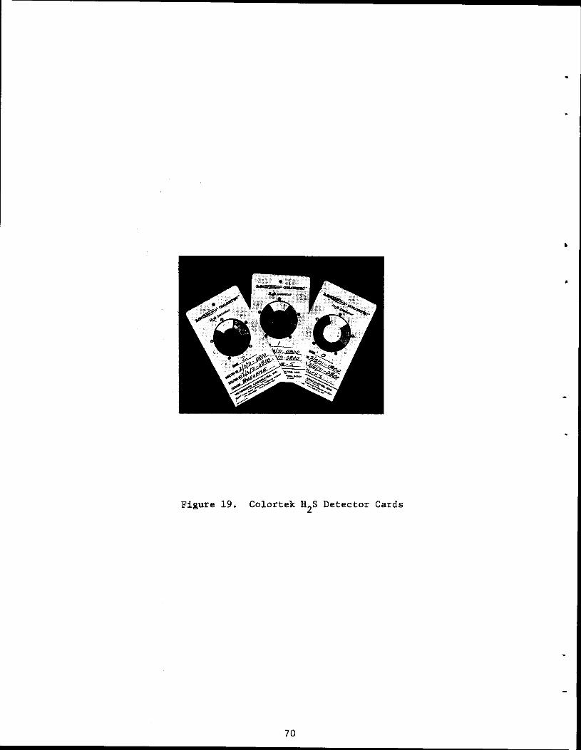
•
Figure 19. Colortek H2s Detector Cards
70
Concentration, ppm
0.02 0.10 5-10
70-150
170-300
400-700
600
Toxicity of Hydrogen Sulfide [3]
Effect
Odor threshold Eye irritation Suggested Maximum Allowable
Concentration (MAC) for prolonged exposure
Slight symptoms after exposure of several hours
Maximum Concentration which can be inhaled for 1 hour without serious consequences
Dangerous after exposure for 1/2 to 1 hour
Fatal with 1/2 hour exposure
On the basis of these effects a MAC value of 5 ppm was specified as the
upper threshold limit for continuous exposure to H2s emissions in areas
normally expected to be occupied by construction or plant personnel.
4.7.2.2. Test Results
The results of the measurements taken of H2S concentrations at various
locations of the construction site and plant given in Tables III to V. Table
III includes data taken at and in the vicinity of the hot mix plant and sulfur
storage area. Table IV contains emissions monitored in the vicinity of the
paving operation. Table V includes all other areas monitored. Data are
presented in a manner to reflect location, sampling agency (TACB, TTl or both),
sampling equipment, average concentration and supporting remarks.
4. 7.2.3. Discussion of Results of H2S Evolved Gas Analysis
As has been reported; as long as the temperature of sulfur/asphalt
systems are maintained below a maximum of 300°F H2s emissions were fo~nd
to be well below suggested MAC values [4, 5]. Except for several occassions
when screed temperature content was lost H2s concentrations as measured in
locations normally frequented by construction personnel were found to be
71
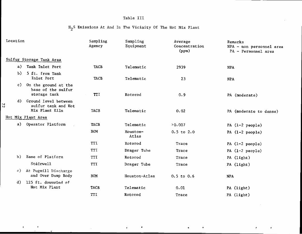
Table III
H2S Emissions At And In The Vicinity Of The Hot Mix Plant
Location Sampling Sampling Average Remarks Agency Equipment Concentration NPA - non personnel area
(ppm) PA - Personnel area
Sulfur Storage Tank Area
a) Tank Inlet Port TACB Telematic 2939 NPA b) 5 ft. from Tank
Inlet Port TACB Telematic 23 NPA c) On the ground at the
base of the sulfur storage tank TTl Rotorod 0.9 PA (moderate)
d) Ground level between " sulfur tank and Hot N
Mix Plant Kiln TACB Telematic 0.02 PA (moderate to dense) Hot Mix Plant Area
a) Operator Platform TACB Telematic >0.007 PA (1-2 people)
BOM Houston- 0.5 to 2.0 PA (1-2 people) Atlas
TTl Rotorod Trace PA (1-2 people)
TTl Drager Tube Trace PA (1-2 people) b) Base of Platform TTl Rotorod Trace PA (light)
Stairwell TTl Drager Tube Trace PA (light) c) At Pugmill Discharge
and Over Dump Body BOM Houston-Atlas 0.5 to 0.6 NPA d) 125 ft. downwind of
Hot Mix Plant TACB Telematic 0.01 PA (light)
TTl Rotorod Trace PA (light)
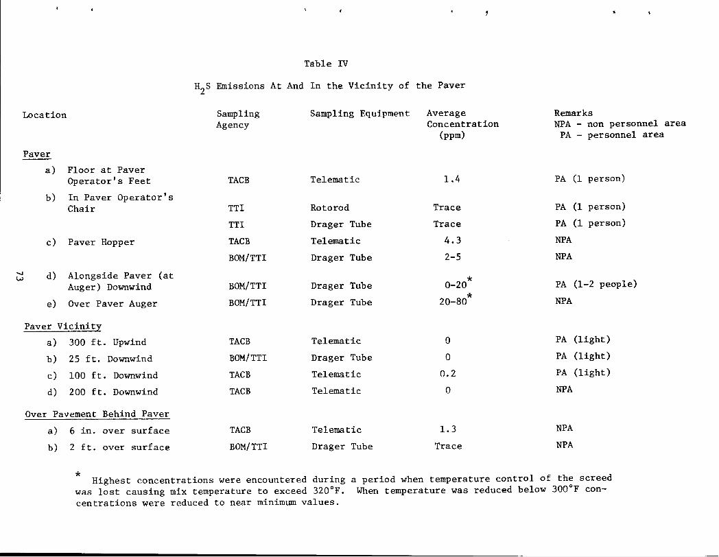
Location
Paver ---
....... w
a) Floor at Paver Operator's Feet
b) In Paver Operator's Chair
c) Paver Hopper
d) Alongside Paver (at Auger) Downwind
e) Over Paver Auger
Paver Vicinity
a) 300 ft. Upwind
b) 25 ft. Downwind
c) 100 ft. Downwind
d) 200 ft. Downwind
Over Pavement Behind Paver
a) 6 in. over surface
b) 2 ft. over surface
Table IV
H2s Emissions At And In the Vicinity of the Paver
Sampling Agency
TACB
TTl
TTl
TACB
BOM/TTI
BOM/TTI
BOM/TTI
TACB
BOM/TTI
TACB
TACB
TACB
BOM/TTI
Sampling Equipment
Telematic
Rotorod
Drager Tube
Telematic
Drager Tube
Drager Tube
Drager Tube
Telematic
Drager Tube
Telematic
Telematic
Telematic
Drager Tube
Average Concentration
(ppm)
1.4
Trace
Trace
4.3
2-5
0-20
20-80
0
0
0.2
0
1.3
Trace
* *
s
Remarks NPA - non personnel area
PA - personnel area
PA (1 person)
PA (1 person)
PA (1 person)
NPA
NPA
PA (1:....2 people)
NPA
PA (light)
PA (light)
PA (light)
NPA
NPA
NPA
* Highest concentrations were encountered during a period when temperature control of the screed was lost causing mix temperature to exceed 320°F. When temperature was reduced below 300°F concentrations were reduced to near minimum values.
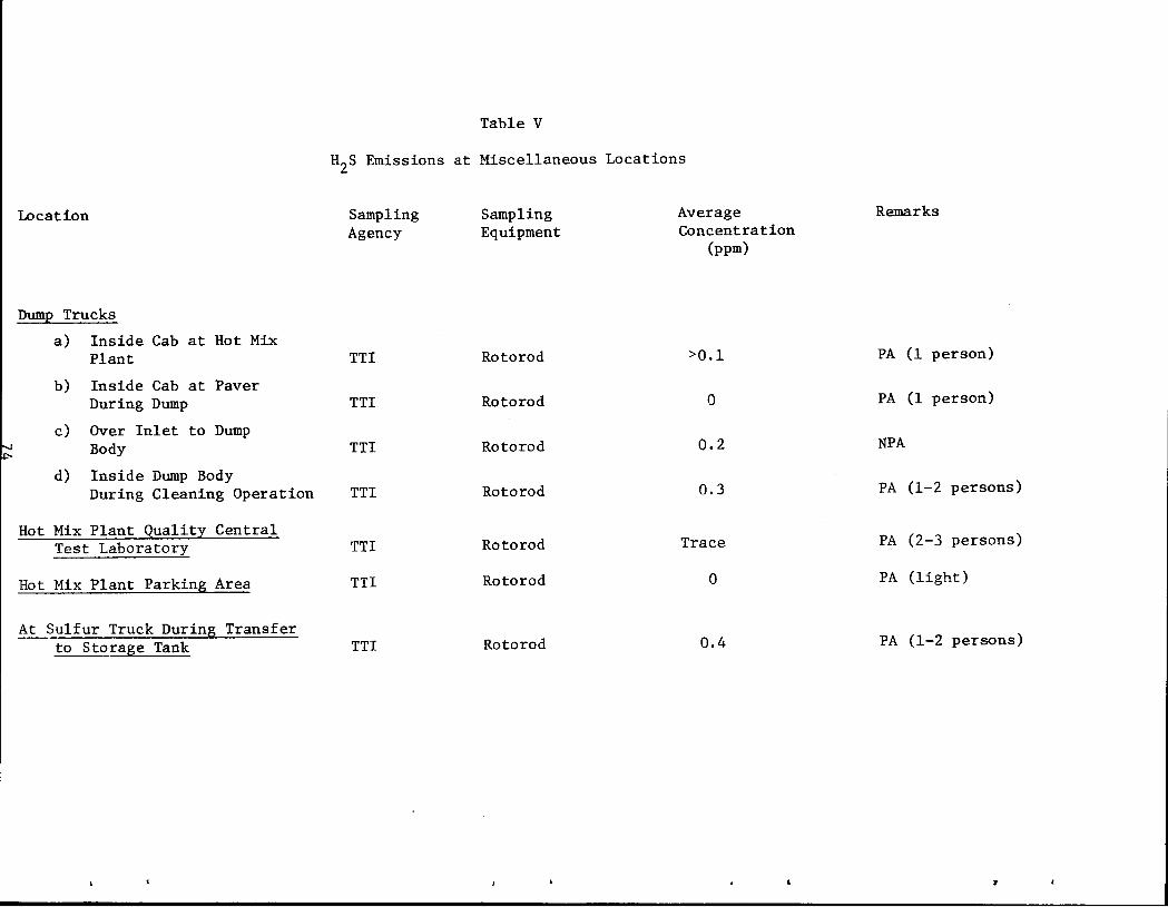
Location
Dump Trucks
a) Inside Cab at Hot Mix Plant
b) Inside Cab at Paver During Dump
c) Over Inlet to Dump Body
d) Inside Dump Body During Cleaning Operation
Hot Mix Plant Quality Central Test Laboratori_
Hot Mix Plant Parking Area
At Sulfur Truck During Transfer to Storage Tank
Table V
H2s Emissions at Miscellaneous Locations
Sampling Agency
TTl
TTl
TTl
TTl
TTl
TTl
TTl
Sampling Equipment
Rotorod
Rotorod
Rotorod
Rotorod
Rotorod
Rotorod
Rotorod
Average Concentration
(ppm)
>0.1
0
0.2
0.3
Trace
0
0.4
Remarks
PA (1 person)
PA (1 person)
NPA
PA (1-2 persons)
PA (2-3 persons)
PA (light)
PA (1-2 persons)
.,
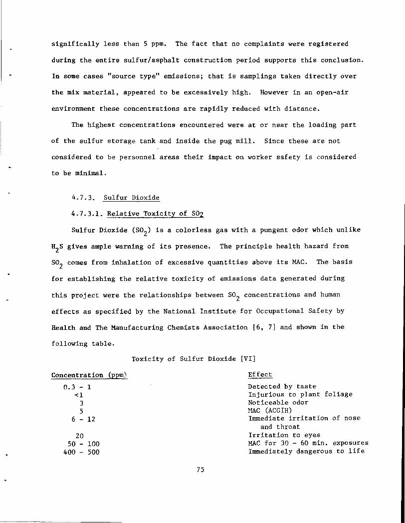
significally less than 5 ppm. The fact that no complaints were registered
during the entire sulfur/asphalt construction period supports this conclusion.
In some cases "source type" emissions; that is samplings taken directly over
the mix material, appeared to be excessively high. However in an open-air
environment these concentrations are rapidly reduced with distance.
The highest concentrations encountered were at or near the loading part
of the sulfur storage tank and inside the pug mill. Since these are not
considered to be personnel areas their impact on worker safety is considered
to be minimal.
4.7.3. Sulfur Dioxide
4.7.3.1. Relative Toxicity of S02
Sulfur Dioxide (S02) is a colorless gas with a pungent odor which unlike
H2s gives ample warning of its presence. The principle health hazard from
so2
comes from inhalation of excessive quantities above its MAC. The basis
for establishing the relative toxicity of emissions data generated during
this project were the relationships between so2 concentrations and human
effects as specified by the National Institute for Occupational Safety by
Health and The Manufacturing Chemists Association [6, 7] and shown in the
following table.
Concentration (ppm)
0.3 - 1 <1
3 5
6 - 12
20 50 - 100
400 - 500
Toxicity of Sulfur Dioxide [VI]
75
Effect
Detected by taste Injurious to plant foliage Noticeable odor MAC (ACGIH) Immediate irritation of nose
and throat Irritation to eyes MAC for 30 - 60 min. exposures Immediately dangerous to life
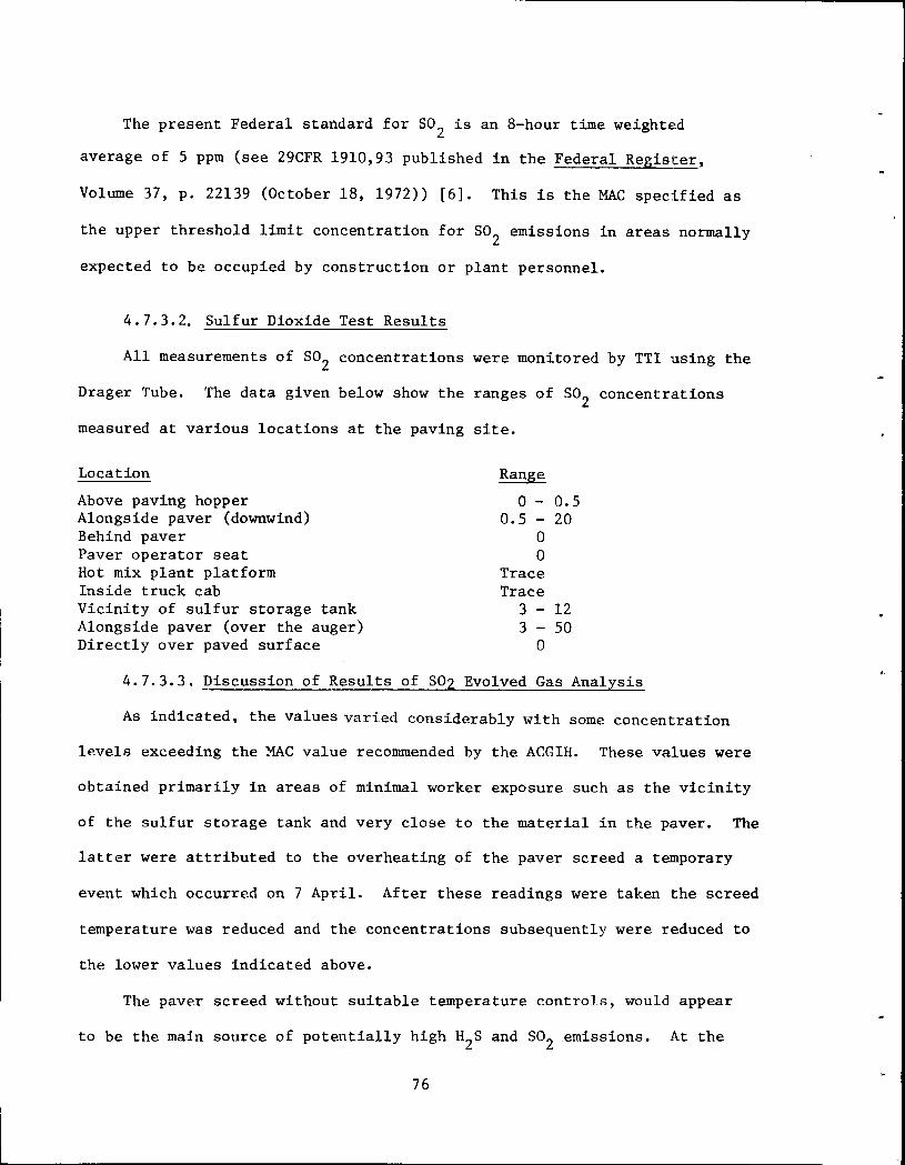
The present Federal standard for so2 is an 8-hour time weighted
average of 5 ppm (see 29CFR 1910,93 published in the Federal Register,
Volume 37, p. 22139 (October 18, 1972)) [6]. This is the MAC specified as
the upper threshold limit concentration for so2
emissions in areas normally
expected to be occupied by construction or plant personnel.
4.7.3.2. Sulfur Dioxide Test Results
All measurements of so2 concentrations were monitored by TTI using the
Drager Tube. The data given below show the ranges of so2
concentrations
measured at various locations at the paving site.
Location
Above paving hopper Alongside paver (downwind) Behind paver Paver operator seat Hot mix plant platform Inside truck cab Vicinity of sulfur storage tank Alongside paver (over the auger) Directly over paved surface
Range
0 - 0.5 o.s - 20
0 0
Trace Trace
3 - 12 3 - so
0
4. 7.3.3. Discussion of Results of S02 Evolved Gas Analysis
As indicated, the values varied considerably with some concentration
levels exceeding the MAC value recommended by the ACGIH. These values were
obtained primarily in areas of minimal worker exposure such as the vicinity
of the sulfur storage tank and very close to the mat~rial in the paver. The
latter were attributed to the overheating of the paver screed a temporary
event which occurred on 7 April. After these readings were taken the screed
temperature was reduced and the concentrations subsequently were reduced to
the lower values indicated above.
The paver screed without suitable temperature controls, would appear
to be the main source of potentially high H2s and so2 .emissions. At the
76
operator and 1t1orkmen levels on the paver and at the hot mix plant platform
gas toxicity were negligible. As in the case with H2s, gas evolution stayed
well below established MAC limits when mix and paving temperatures were
maintained under 300°F.
4.7.4. Particulate Sulfur
4.7.4.1. Occurrence and Toxicity
Vapor given off during mixing and dumping operations contain a certain
amount of undissolved and unreacted sulfur. As the vapors come in contact
with air and cool, the sulfur vapor crystallized into small particles which
are carried by the wind in a manner similar to dust and fine sands. Since
there is no practical way to eliminate this pollutant its effect on both
environment and personnel need to be considered.
As mentioned above TACB had accepted the responsibility for collecting
these data during construction of the sulfur/asphalt pavement. However,
particulate sulfur samplings were not taken. This section will be devoted
to a discussion of the relative hazards associated with sulfur dust on
construction personnel as specified by the Manufacturing Chemists Association
[7, 8]. Assessments of the environmental impact of this pollutant is
considered to be beyond the scope of this task.
The principal problems associated with sulfur dust lie in its contact
with eyes. Sulfur is virtually nontoxic and there is no evidence that systemic
poisoning results from the inhalation of sulfur dust. However, sulfur is
capable of irritating the inner surfaces of the eyelids. Sulfur dust may
rarely irritate the skin. This problem is minimized by the requirement that
goggles bl~ worn in areas subject to this pollutant such as at the hot mix
plant and in the vicinity of the paver.
77
The primary hazard in handling solid sulfur results from the fact that
sulfur dust suspended in air may be ignited. This problem is almost always
limited to enclosures and unventilated areas. Since this is not typical of
the hot mix plant or the paving area this particular hazard is not .~ major
concern.
To minimize possible irritation, unnecessary contact with skin and eyes
should be avoided. Following the work period, sulfur dust should be removed
with mild soap and water. For relief of eye irritation, eyes should be
thoroughly flushed with large quantities of plain water of physiological
saline. Inadequate amounts of water may actually increase eye irritation.
4.7.5. Sununary of Evolved Gas Analysis
Three forms of sulfur pollutants were discussed; H2s, S02 and sulfur
dust. Except for a time interval during which the temperature of the pave
screed was allowed to exceed 300°F concentrations of the two gaseous
pollutants remained below recommended allowable threshold limit. This
condition indicates the need to provide positive temperature controls at
both the hot mix plant and the paver.
Although the amounts of sulfur dust generated during construction
were not monitored as planned, experience dictates that the only major
hazard to personnel lies in irritation to eyes. Safety goggles are
recommended to offset this problem. No data taken as yet would indicate
that sulfur dust is present in sufficient quantities to create a health
hazard. It is recommended that data on sulfur dust be generated on any
future sulfur-asphalt field trials.
The location where highest concentrations of H2S and so2 were present
was in the sulfur storage area; more specifically near the loading ports
of the storage tank. This is not considered a personnel area. Furthermore,
78
the concentrations of the pollutants decrease rapidly with distance thus
eliminating this area as a potential safety hazard to plant workmen.
~rmally accepted safety practices should be employed during transfer of
hot sulfur from delivery trucks to the storage tanks.
79
REFERENCES
1. Elkins, Hervey, B., The Chemistry of Industrial Toxicology, John Wiley and Sons, Inc., New York, pp. 95, 232, (1950).
2. Stolman, A., ed., Progress in Chemical Toxicology, Academic Press, New York, Vol. 1, p. 10, (1965).
3. Hydrogen Sulfide, Chemical Safety Data Sheet DS-36, Manufacturing Chemists Association, Washington, D.C., (Revised 1968).
4. Deyne, I., "Basic Properties of Sand-Asphalt-Sulfur Mills," International Road Federation World Meeting, 7th, Munich, (Octoher 1973).
5. "Beneficial Uses of Sulfur in Sulfur - Asphalt Pavement" Final Report, Volume I-A on Texas A&M Research Project- RF983, (May 1973).
6. Occupational Exposure to Sulfur Dioxide-Criteria Document, U. S. Department of Health, Education and Welfare document published by Public Health Service Center for Disease Control, National Institute for Occupational Safety and Health, (1974).
7. Sulfur Dioxide, Chemical Safety Data Sheet SD-52, Manufacturing Chemist Association, Washington D.C., (1959).
8. Sulfur, Chemical Safety Data Sheet SD-74, Manufacturing Chemist Association, Washington, D.C., (1959)
80
• i I
5.0 Quality Control
5.1 Field Labor~tory Personnel and Equipment
The State Department of Highways and Public Transportation, District
21, as usual for field control of pavement construction, provided a
mobile laboratory.
The laboratory and hot-mix plant inspection were under the immediate
supervision of Sim Giles, Engineering Technician. He was assisted by
George Barrera, Engineering Technician, F. J. Gonzales, Engineering Aide
and Ed Ellis, Laboratory Assistant from Texas Transportation Institute.
The equipment available for field testing included:
1. A TROXLER Nuclear Asphalt Gauge, Model 2226, TROXLER Laboratories, Raleigh, North Carolina,
2. Marshall Apparatus complete with automatic compaction hammer, special molds, breaking head and compression testing machine (provided by TTI),
3. Rotary type extractor,
4. A mechanical seive shaker with electric motor drive,
5. An 18-in. x 24-in. x 30-in. oven,
6. A muffle furnace, BLUE M (2000F Max.),
7. A gyratory compactor for Hveem specimens and
8. :.n improvised 1 blast Furnace 1 •
Also miscellaneous scales, thermometers, sample containers, etc.
5.2 Schedule of Testing
The. following schedule was used by the field laboratory personnel
as a gufde:
81
1. Check temperature of each truck load of mix and record,
2. Make slump tests as required to monitor consistency o:E the mixtures,
3. Determine binder content of mixtures - asphalt and sulfur,
4. Make set of 9 Marshall test specimen at least twice daily; three specimen to be tested in field at 24 hrs., six specimen to be taken for TTI,
5. Take 40 lbs. of mixture each 1/2 day of operation and place in containers for TTI and
6. When plant is lined out take one 200 lb. sample of mixture for study by TTL
5.3 Mix Design
The mix design for the sand-asphalt-sulfur pavement mixture was a
result of extensive laboratory tests by Texas Transportation Institute
some weeks prior to beginning the job. These data are presented in Table
VI.
The mix design data reviewed by Shell Canada, were based on the
blend of 65/35 w/o of the 'Bluntzer' concrete type sand and the field sand,
respectively. See Mineral Aggregates Section 2.3. Shell's confirmatory
mix design information is shown in Table VII.
The mix design selected was as follows:
Asphalt, AC-20 ----------------------6.2 w/o of Mix
Sulfur -----------------------------13.0 w/o of Mix
65/35 w/o sand blend --------------80, 8 w/o of Mix
This design, once selected, was not changed for the duration of the
project. Selection was based on a minimum Marshall Stability of 2,000 lbs.
of ASTM Cl43-74 and a slump of 2 to 6 inches. Shell Canada's
82
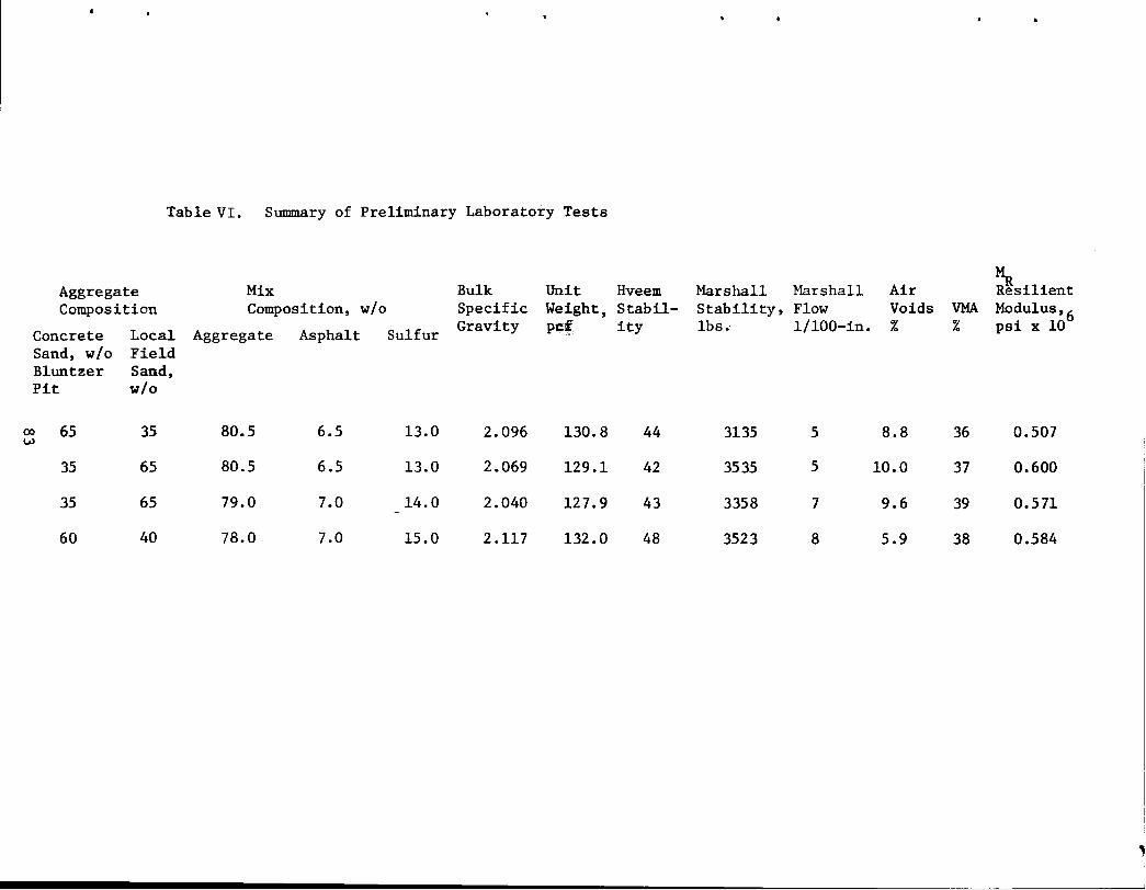
Table VI. Summary of Preliminary Laboratory Tests
Aggregate Mix Bulk Unit Hveem Composition Composition, w/o Specific Weight, Stabil-
Concrete Local Aggregate Asphalt Sulfur Gravity pe~ ity
Sand, w/o Field Bluntzer Sand, Pit w/o
00 65 35 80.5 6.5 13.0 2.096 130.8 44 w
35 65 80.5 6.5 13.0 2.069 129.1 42
35 65 79.0 7.0 14.0 2.040 127.9 43 -
60 40 78.0 7.0 15.0 2.117 132.0 48
Marshall Marshall Air Stability, Flow Voids lbs. 1/100-in. %
3135 5 8.8
3535 5 10.0
3358 7 9.6
3523 8 5.9
VMA %
36
37
39
38
~ Resilient Modulus, 6 psi x 10
0.507
0.600
0.571
0.584
, I
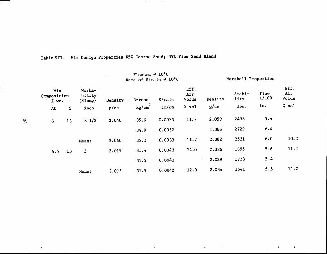
Table VII. Mix Design Properties 65% Coarse Sand; 35% Fine Sand Blend
Flexure @ l0°C Rate of Strain @ l0°C Marshall Properties
Mix Worka- Eff. Eff.
Composition bility Air Stabi- Flow Air
% wt. (Slump) Density Stress Strain Voids Density lity 1/100 Voids
g/cc 2 em/em % vol g/cc in.
AC s inch kg/em lbs. % vol
CX> 6 13 3 1/2 2.040 35.6 0.0033 11.7 2.059 2498 5.4 .1:-
34.9 0.0032 2.066 2729 6.4
Mean: 2.040 35.3 0.0033 11.7 2.082 2531 6.0 10.2
6.5 13 5 2.015 31.4 0.0043 12.0 2.036 1695 5.6 11.2
31.5 0.0043 2.029 1728 5.4
Mean: 2.015 31.5 0.0042 12.0 2.034 1541 5.5 11.2
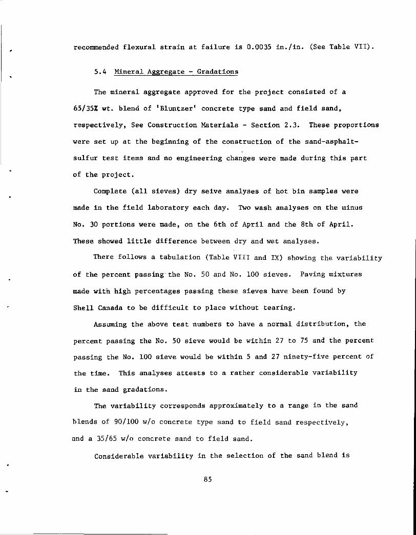
recommended flexural strain at failure is 0.0035 in./in. (See Table VII).
5.4 Mineral Aggregate - Gradations
The mineral aggregate approved for the project consisted of a
65/35% wt. blend of 'Bluntzer' concrete type sand and field sand,
respectively, See Construction Materials - Section 2.3. These proportions
were set up at the beginning of the construction of the sand-asphalt
sulfur test items and no engineering changes were made during this part
of the project.
Complete (all sieves) dry seive analyses of hot bin samples were
made in the field laboratory each day. Two wash analyses on the minus
No. 30 portions were made, on the 6th of April and the 8th of April.
These showed little difference between dry and wet analyses.
There follows a tabulation (Table VIII and IX) showing the variability
of the percent passing the No. 50 and No. 100 sieves. Paving mixtures
made with high percentages passing these sieves have been found by
Shell Canada to be difficult to place without tearing.
Assuming the above test numbers to have a normal distribution, the
percent passing the No. 50 sieve would be within 27 to 75 and the percent
passing the No. 100 sieve would be within 5 and 27 ninety-five percent of
the time. This analyses attests to a rather considerable variability
in the sand gradations.
The variability corresponds approximately to a range in the sand
blends of 90/100 w/o concrete type sand to field sand respectively,
and a 35/65 w/o concrete sand to field sand.
Considerable variability in the selection of the sand blend is
85
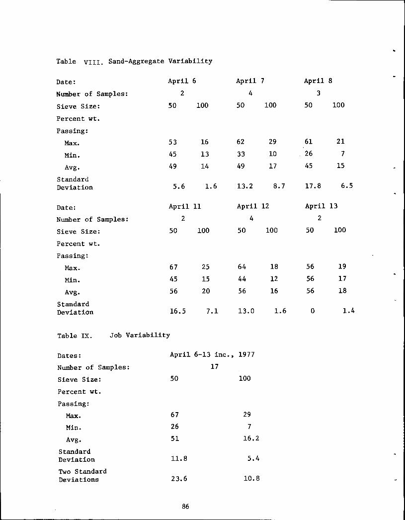
.. Table VIII. Sand-Aggregate Variability
Date: April 6 April 7 April 8
Number of Samples: 2 4 3
Sieve Size: 50 100 50 100 50 100
Percent wt.
Passing:
Max. 53 16 62 29 61 21
Min. 45 13 33 10 26 7
Avg. 49 14 49 17 45 15
Standard Deviation 5.6 1.6 13.2 8.7 17.8 6.5
Date: April 11 April 12 April 13
Number of Samples: 2 4 2
Sieve Size: 50 100 50 100 50 100
Percent wt.
Passing:
Max. 67 25 64 18 56 19
Min. 45 15 44 12 56 17
Avg. 56 20 56 16 56 18
Standard Deviation 16.5 7.1 13.0 1.6 0 1.4
Table IX. Job Variability
Dates: April 6-13 inc., 1977
Number of Samples: 17
Sieve Size: 50 100
Percent wt.
Passing:
Max. 67 29
Min. 26 7
Avg. 51 16.2
Standard Deviation 11.8 5.4
Two Standard Deviations 23.6 10.8
86
..
•
permitted by the project specification brackets. See Figure 5 •
At the same time the specification, Item 2029, also provide that,
"The proportioning device (cold bin feed, etc.) shall be such as will
provide a uniform and continuous flow of aggregates in the desired
proportions to the dryer".
Needless to say, variation is the norm on most jobs and more
particularly so on projects such as this one. It should be pointed out
that the variations shown by the above analysis includes the entire
parade of events and further it should be stated that in general the
operation was such as to result in a fairly uniform product. Core
analyses, yet to be made, will most likely verify this contention.
5.5 Temperature Control of the Mixture
The oil burner on the dryer was manually operated by the plant
superintendent. He was guided by an automatic temperature recorder on
the hot-elevator and by his skill and long experience in regulating the
unit. Temperature control of the S-A-S mixtures was generally good.
As a further aid in temperature control, Shell Canada engineers
installed a thermocouple in the No. 1, sand, bin and attached it to a
recorder with an alarm set at 300F.
Table X contains a summary of the temperatures of the sand-asphalt
sulfur pavement mixtures as recorded by the State Engineers at the hot
mix plant and in the field.
87
•
Table X. Variability of Mix Temperatures
Date: April 6 April 7 April 8
Location: Hot-plant Field Hot-plant Field Hot-plant Field
Number of:
Measurements: 7 7 16 22 24 20
Max. OF 310 290 300 305 305* 290
Min. OF 240 255 265 255 275 265
Avg. 282 278 289 289 286 277
Standard Deviation:
*Does not include one load at 32~ which was wasted.
Date: April 11 April 12 April 13
Location: Hot-plant Field Hot-plant Field Hot-plant Field
Number of:
Measurements: 11 8 26 24 24 25
Max. OF 305 285 300 295 300 290
Min. OF 275 275 265 265 265 255
Avg. 287 280 285 279 283 279
Standard Deviation: 6.7 6.3
Two Standard Deviations: 13.4 12.6
88
The variability, as determined by the Standard Deviation, has been
calculated for one day only, April 12. Assuming the test numbers to
have a normal distribution, the temperature of the sand-asphalt-sulfur
pavement mixture at the hot-plant would be with a range of 272 to
298F ninety-five percent of the time. In the field the range would be
266 to 292F. These temperatures correspond to the working range
considered to be acceptable for S-A-S systems.
Temperatures were measured in the top of the loaded truck at the
hot-plant and in the paver hopper in the field. Between these two
points a rather consistent loss of about 6F was experienced.
5.6 Sulfur-Asphalt Contents
Shell Canada engineers provided a 'Tentative Test Method for the
Determination of Bitument Content and Sulfur Content in THERMOPAVE
(sand-asphalt-sulfur) Mix' (see Appendix B). Copies are on file with
Texas Transportation Institute. The basics of the procedure were used
by the State engineers. They follow:
1. The asphalt content is determined using a TROXLER Nuelear Asphalt Density Gauge.
2. The asphalt and some sulfur are extracted using a rotary extractor.
3. A representative portion or the entire sample from Step 2. is heated in a crucible to burn off the remaining sulfur.
4. The sulfur content is determined by subtracting the asphalt, Step 1. from total asphalt plus sulfur, Steps 2. and 3.
There follows (See Table XI) a tabulation, from the State engineers
field laboratory records, showing the date, load number for that date,
89
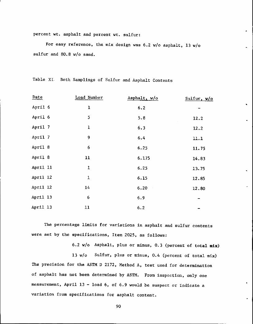
percent wt. asphalt and percent wt. sulfur:
For easy reference, the mix design was 6.2 w/o asphalt, 13 w/o
sulfur and 80.8 w/o sand.
Table XI Both Samplings of Sulfur and Asphalt Contents
Date Load Number AsEhalt 2 w/o Sulfur,
April 6 1 6.2
April 6 5 5.8 12.2
April 7 1 6.3 12.2
April 7 9 6.4 11.1
April 8 6 6.25 11.75
April 8 11 6.175 14.83
April 11 1 6.25 13.75
April 12 1 6.15 12.85
April 12 14 6.20 12.80
April 13 6 6.9
April 13 11 6.2
w/o
The percentage limits for variations in asphalt and sulfur contents
were set by the specifications, Item 2025, as follows:
6.2 w/o Asphalt, plus or minus, 0.3 (percent of total mix)
13 w/o Sulfur, plus or minus, 0.4 (percent of total mix)
The precision for the ASTM D 2172, Method A, test used for determination
of asphalt has not been determined by ASTM. From inspection, only one
measurement, April 13 - load 6, of 6.9 would be suspect or indicate a
variation from specifications for asphalt content.
90
..
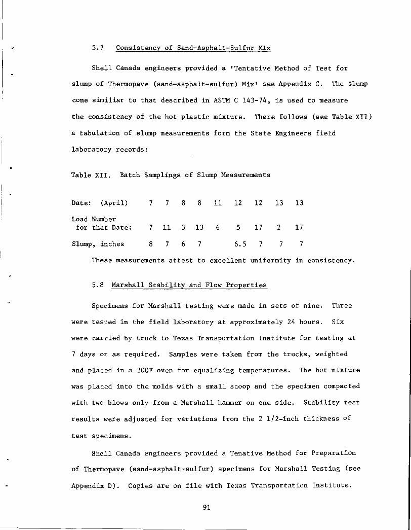
.. 5.7 Consistency of Sand-Asphalt-Sulfur Mix
Shell Canada engineers provided a 'Tentative Method of Test for
slump of Thermopave (sand-asphalt-sulfur) Mix' see Appendix C. The slump
cone similiar to that described in ASTM C 143-74, is used to measure
the consistency of the hot plastic mixture. There follows (see Table XII)
a tabulation of slump measurements form the State Engineers field
laboratory records:
Table XII. Batch Samplings of Slump Measurements
Date: (April) 7 7 8 8 11 12 12 13 13
Load Number for that Date: 7 11 3 13 6 5 17 2 17
Slump, inches 8 7 6 7 6.5 7 7 7
These measurements attest to excellent uniformity in consistency.
5.8 Marshall Stability and Flow Properties
Specimens for Marshall testing were made in sets of nine. Three
were tested in the field laboratory at approximately 24 hours. Six
were carried by truck to Texas Transportation Institute for t~sting at
7 days or as required. Samples were taken from the trucks, weighted
and placed in a 300F oven for equalizing temperatures. The hot mixture
was placed into the molds with a small scoop and the specimen compacted
with two blows only from a Marshall hammer on one side. Stability test
results were adjusted for variations from the 2 1/2-inch thickness of
test specimens.
Shell Canada engineers provided a Tenative Method for Preparation
of Thermopave (sand-asphalt-sulfur) specimens for Marshall Testing (see
Appendix D). Copies are on file with Texas Transportation Institute.
91
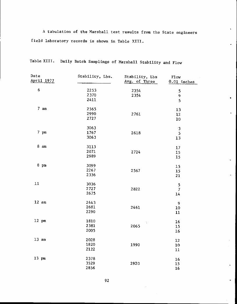
A tabulation of the Marshall test results from the State engineers
field laboratory records is shown in Table XIII.
Table XIII. Daily Batch Samplings of Marshall Stability and Flow
Date Stability, Lbs. Stability, Lbs Flow April 1977 Avg. of Three 0.01 inches
6 2253 2354 5 2370 2354 9 • 2411 5
7 am 2565 13 2990 2761 12 2727 10
3063 3 7 pm 1767 2618 5
3063 13
8 am 3113 17 2071 2724 15 2989 15
8 pm 3099 15 2267 2567 15 2336 21
11 3036 5 2727 2822 7 2675 14
12 am 2443 9 2681 2461 10 2290 11
12 pm 1810 16 2381 2065 15 2005 16
13 am 2028 12 1820 1990 10 2122 11
13pm 2378 16 3529 2920 15 2856 16
92
6.0 Conclusions
The overall objective of this experimental construction project
was to evaluate the potential of using sulfur as a means of producing a
quality sand-asphalt-sulfur paving mixture using a poorly graded dune
sand as an aggregate. The techniques used in the field were basically
those developed by Shell Canada and verified by the Texas Transportation
Institute in the laboratory. These techniques were subsequently demonstrated
in the successful construction of the full scale field sections discussed
in this report.
Specific results of the project at this point can be summarized
as follows:
1. A sand-asphalt-sulfur paving mixture with respective weight
percent ratios of 80.8-6.2 and 13.0 of the total mix was successfully
placed using techniques developed by Shell Canada.
2. Limitations in the design of the paver required that a 65/35
weight percent ratio of coarse to fine (local) sand be used to prevent
tearing. At one point 100 percent local sand was placed with acceptable
surface quality.
3. Because of the age and efficiency of the hot-mix plant used in
the project, batch-to-batch variability was not as good as would be
expected in a more modern plant. Part of the problem in maintaining
a consistent quality paved surface can be attributed to variables
in the hot-mix plant operations.
4. The heated dump bodies furnished by Shell performed well
throughout the project. This job reconfirmed the need for heated dump
93
bodies as an input to the success of this type of operation.
5. The need for good temperature control of the mix at the hot
mix pl~•t and at the paver was demonstrated. At one point excessive
temperature at the paver screed produced high emissions of H2s and so2•
When the temperature was reduced, the emissions dropped to their normal,
safe levels.
6. Cores taken from the finished pavement showed excellent bond
strength between successive layers of the S-A-S base.
94
•
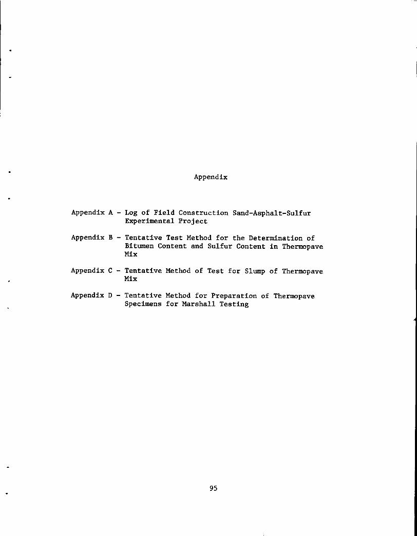
Appendix
Appendix A - Log of Field Construction Sand-Asphalt-Sulfur Experimental Project
Appendix B - Tentative Test Method for the Determination of Bitumen Content and Sulfur Content in Thermopave Mix
Appendix C - Tentative Method of Test for Slump of Thermopave Mix
Appendix D - Tentative Method for Preparation of Thermopave Specimens for Marshall Testing
95

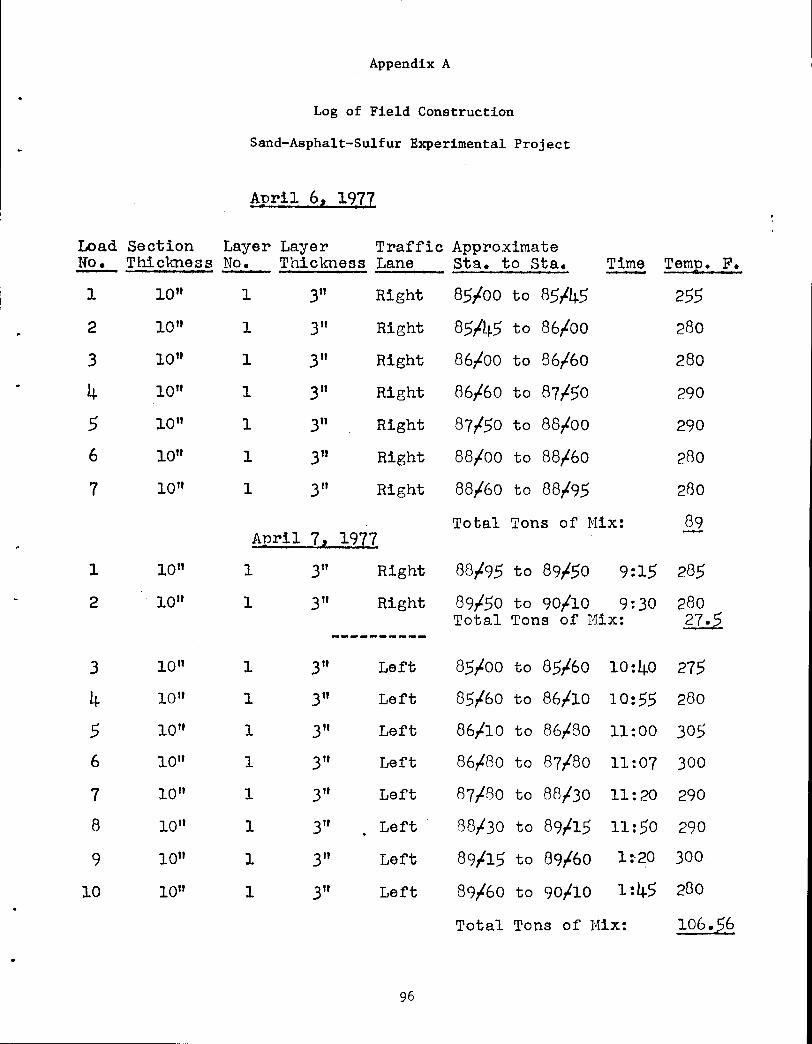
Appendix A
Log of Field Construction
Sand-Asphalt-Sulfur Experimental Project
April 6, 1977
Load Section Layer Layer Traffic Approximate No. Thiclmess No. Thiclmess Lane Sta. to Sta. Time TamE• F.
1 1011 1 3" Right 85loo to 85145 255 2 10" 1 3" Right 85145 to 86,Loo 280
3 1011 1 3" Right 86,Loo to 86/60 280
4 1011 1 3" Right 86,L6o to 87/50 290
5 10" 1 3" Right 87,L5o to 88/00 290
6 1011 1 3" Right 88,Loo to 88,L6o 280
7 1011 1 3" Right 88,L6o to 88,L95 280
Total Tons of Mix: 89 AEril 7, 1977
1 1011 1 3" Right 88,L95 to 89150 9:15 285
2 10" 1 3" Right 89l5o to 90/10 9:30 280 Total Tons of Mix: £0.
----------3 1011 1 3" Left 85,too to 85l6o 10:40 275
4 10" 1 3" Left 85/60 to 86/10 10:55 280
5 10" 1 3" Left 86/10 to 86/80 11:00 305 6 10" 1 3" Left 86,L8o to 87,L8o 11:07 300
7 10" 1 3" Left 87/BO to 88/30 11:20 290
8 10" 1 3" Left t38/30 to 89115 11:50 290
9 1011 1 3" Left 89115 to 89l6o 1:·20 300
10 10" 1 3" Left 89,t6o to 90/10 1:45 280
Total Tons of Mix: 106.,26
96
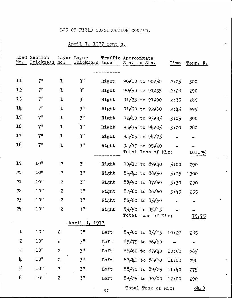
LOG 0? FIE:LD CONSTRUCTION CONTtD.
April 7, 1977 Conttd.
Load Section Layer Layer Traffic Apnroximate No. Thiclmess No. Thickness Lane Sta. to Sta. Time Temp. F.
----------11 7" 1 3" Right 90/10 to 90I5o 2:25 300
12 7" 1 3" Right 90I5o to 91135 2:28 290
13 7" 1 3" Right 91135 to 91190 2:35 285
14 7" 1 3" Right 91190 to 92l6o 2:45 295
15 7" 1 3" Right 92l6o to 93135 3:05 300 16 7" 1 3" Right 93/35 to 94105 3:20 280
17 7" 1 3" Right 94105 to 94175 18 7" 1 3" Right 94175 to 95120
Total Tons of Mix: 101.25 ----------19 1011 2 3" Right 90110 to S914o 5:00 290 20 1011 2 3" Right 89/40 to 88l5o 5:15 '300
21 10" 2 3" Ri[Sht 88l5o to 87l6o 5:30 290 22 10 11 2 3" Right 87/60 to 86/60 5:45 255 23 10" 2 3" Right 86/60 to 85150 24 10" 2 3" Rir.;ht 85l5o to 85115
Total Tons of Mix: 75.72. AEril 8! 1977
1 10" 2 3" Left 85loo to 85175 10:27 285
2 1011 2 3" Left 85175 to 86l6o
3 10" 2 3" Left 86l6o to R714o 10:50 265
4 1011 2 3" Left 87140 to 8R,L70 11:00 290
5 1011 2 3" Left 88170 to 89125 11:40 275 6 1011 2 3" Left 89/25 to 90ioo 12:00 290
97 Total Tons of Mix: 84.0
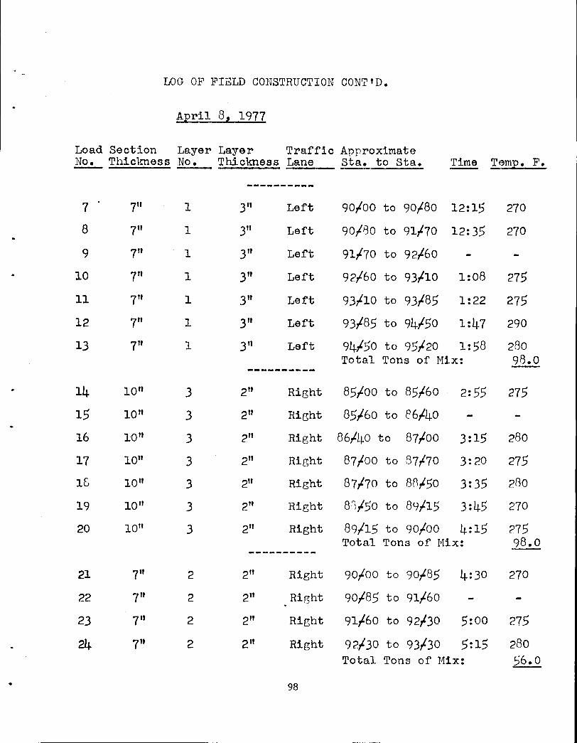
LOG OF FIELD CONSTRUCTION CONT'D.
April 8, 1977
Load Section Layer Layer Traffic Approximate No. Thiclmess No. Thiclmess Lane Sta. to Sta. Time Temp. F.
----------7 7" 1 3" Left 90/00 to 90/80 12:15 270
8 7" 1 3" Left 90/80 to 91/70 12:35 270
9 7" 1 3" Left 91/70 to 92/60
10 7" 1 3" Left 92/60 to 93t10 1:08 275
11 7" 1 3" Left 93t10 to 93185 1:22 275
12 7" 1 3" Left 93/85 to 94t50 1:47 290
13 7" 1 3" Left 94/50 to 95/20 1:58 280 Total Tons of Mix: 98.0
----------14 10" 3 2" Right 85/00 to 85,l6o 2:55 275
15 10" 3 2" Right 85/60 to e6,l4o
16 1011 3 2" Right 86/40 to 87t00 3:15 280
17 10" 3 2" Right 87t00 to 87/70 3:20 275
16 1011 3 2" Right 87/70 to 8A,l5o 3:35 280
19 10 11 3 2" Right 8~/50 to 89,l15 3:45 270
20 1011 3 2" Right 89/15 to 90/00 4:15 275 Total Tons of Mix: 98.0
----------21 7" 2 2" Right 90/00 to 90/85 4:30 270
22 7" 2 2" Right 90/85 to 9l,l6o
23 7" 2 2" Right 91/60 to 92t30 5:00 275
24 7" 2 2" Right 92,l30 to 93,l30 5:15 280 Total Tons of Mix: 56.0
• 98
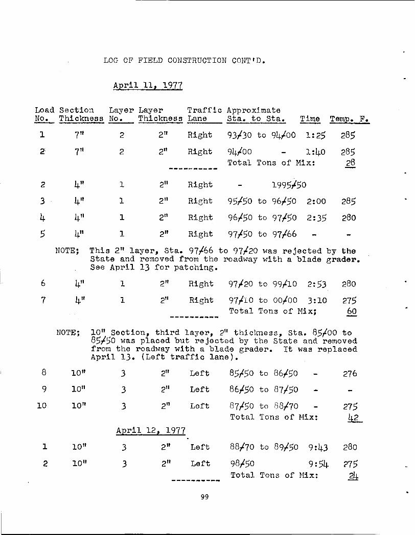
l
LOG OF FIELD CONSTRUCTION COHT'D.
April 11, 1977
Load Section Layer Layer Traffic Approximate No. Thickness No. Thickness Lane Sta. to Sta. ~ Temp. F.
2
3
4 5
6
7
8
9
10
1
2
7"
7"
4"
4"
4"
4"
2
2
1
1
1
1
2" Right 93/30 to 94/00 1:25 285
285 28
2" Right 94/00 1:40
2"
2"
2"
2"
Total Tons of Mix: --------- ... -
Right 1995/50
Right 95/50 to 96/50 2:00 285
Right 96/50 to 97/50 2:35 280
Right 97/50 to 97/66
NOTE; This 2" layer, Sta. 97/66 to 97/-20 was rejected by the State and removed from the roadway with a blade erader. See April 13 for patching.
4" 4"
NOTE;
10"
1011
1011
1011
10"
1
1
2"
2"
Right 97/-20 to 99/10 2:53
Right 97/lO to oo,too 3:10 Total Tons of Mix;
280
275 60
1011 Section, third layer, 2" thickness, Sta. 85/-00 to 85/50 was placed but rejected by the State and removed from the roadway with a blade grader. It was replaced April 13. (Left traffic lane).
3
3
3
2"
2"
2"
Left
Left
Left
April 12, 1977
3
3
2" Left
2" Left
99
85/-50 to 86/50
86/50 to 87150
87/50 to 88/-70 Total Tons of Mix:
88/70 to 89/50 9:43
98/50 9:54 Total Tons of Jviix:
276
215
k
280
275 .?Jt
•
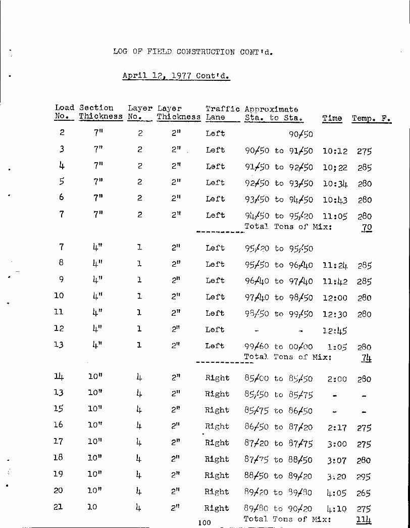
LOG OF FIELD CONSTRUCTION CONTtd.
April 121 1977 Cont'd.
Load Section Layer Layer Traffic Approximate No. Thickness No. Thickness Lane Sta. to Stao Time Teml2• F.
2 7" 2 2" Left 90/50
3 7" 2 2" Left 90/50 to 91/50 10:12 275
4 7" 2 2" Left 9l,L5o to 92,L5o 10;22 285
5 7" 2 2" Left 92,£50 to 93150 10:34 280 6 7" 2 2" Left 93150 to 94,L5o 10:43 280
7 7" 2 2" Left 94/50 to 95,!20 11:05 280 Total Tons of Mix: 1Q
_________ _,
7 4" 1 2" Left 95/20 to 95/50 8 4" 1 2" Left 95/50 to 96/40 11:24. 285
9 4" 1 2" Left 96,L4o to 97140 11~42 285
10 4" 1 2" Left 97/l.j.O to 98/r)O 12:00 280
11 4" 1 2" Left 98/50 to 99/50 12:30 280
12 4" 1 2" Left 12~45
13 4" 1 2" Left 99/60 to oo,loo 1:05 280 Total Tons of Hix: :& _________ ,.. __
14 1011 4 2" Right 85,too to 85,L5o 2:00 280 13 1011 4 2" Right 85,!50 to 85175 15 10" 4 2" Right 85175 to 86/So 16 10 11 4 2" Right 86/50 to 87f20 2:17 275 17 10" 4 2" Right 87/-20 to 87175 3:00 275 18 10" 4 2" Right 871?5 to 88,150 3:07 280 19 10" 4 2" Right 88,L5o to 89f20 3~20 295
• 20 10 11 4 2" Right 89/20 to E39fRo 4:05 265 21 10 4 2" Right 89/80 to 90/20 4:10 275
100 Total Tons of Hix: 11J±

LOG OF FIELD CONSTRUCTION CONTtD.
April 12, 1977 Continued _ .. ________
Load Section Layer Layer Traffic Approximate No. Thickness No .. Thiclmess ~~ Sta..!-to Sta. Time Tem;e. Fo
21 7" 3 2" Right 90f20 to 90/l~O
22 7" 3 2" Right 90;£!~0 to 91/L~o J+~ 20 290
23 7" 3 2'~ Right 9lfL~o to 92./.75 4~ .30 28.5 24 7" 3 2" Right 92/-?5 to 9.3/So 4.:50 270 25 7" 3 21t Right 93/50 to 91.~/~?5 5:15 285 26 7" 3 2" Right 9~./-25 to 95t20 5:30 265
Total Tons of Mix: ~ ________ _,_
AEril 132 1977
1 4" 2 2" Right 95,'20 to 95170 8:50 280
2 4" 2 2" Rie;ht 95/-70 :co 96.t8o 9~00 i
3 4" 2 2" Right 96/-50 to 97t80 9:15 290
4 4" 2 2" Right 97/-t30 to 9B,t5o 9:30 280
5 4" 2 2" Right 98/50 to 99,400 9:45 290 6 4" 2 2" Right 99/00 to 99/90 10:05 280
Total Tons of' Mix: }1:·..2 _________ _,
7 10" 4 2" Left 85/-00 to 85/25 12:00 275 8 1011 4 2" Left 85/25 to 8_5/65 12:05 280
NOTE; Loads 7 and 8 Here placed in an approximately 4" layer to bring Sta. 85/-00 to 85/-50 to grade since layer 3 had been rejected and removed in this segment,
9 1011 4 2" Left 85,L65 to 86/25 12:15 280 10 10" 4 2" Left 86/-25 to 86,!90 12:31 265
101 •
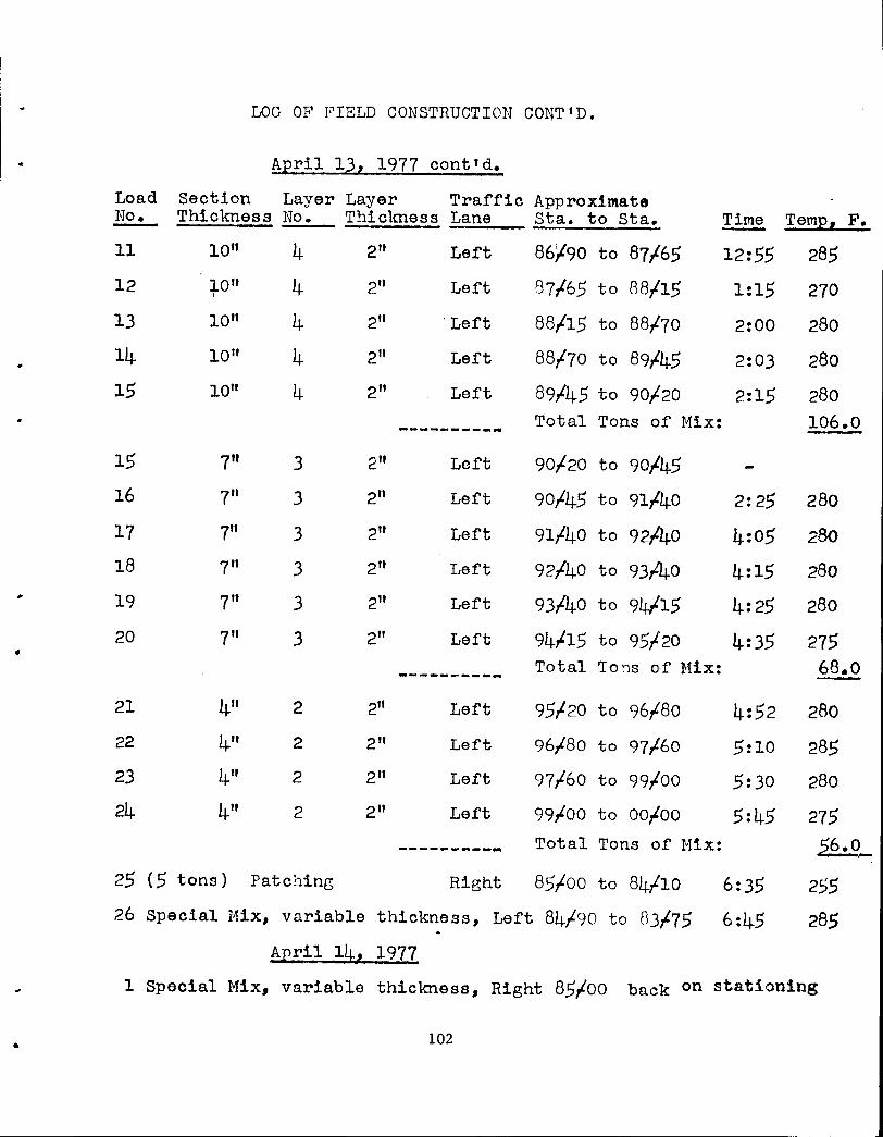
LOG OF F'IELD CONSTRUCTION CO!'lT 'D.
April 13, 1977 cont'd.
Load Section Layer Layer Traffic Approximate No. Thickness No. Thiclmess Lane Sta. to Sta. Time Tem12 2 F.
11 10" 4 2" Left 86'190 to 87/65 12:55 285 12 1011 4 2" Left B?/65 to 88/15 1:15 270 I
13 10" 4 211 'Left 88/15 to 88/70 2:00 280
14 10" 4 211 Left 88/70 to 89145 2:03 280
15 1011 4 2" Left 89/45 to 90,L20 2:15 280
---------- Total Tons of Mix: 106.0
15 7" 3 211 Left 90/20 to 90/45
16 7" 3 2" Left 90/45 to 91/40 2:25 280
17 711 3 2" Left 91/40 to 92/40 4:05 280
18 7" 3 211 Left 92/40 to 93/40 4:15 280
19 711 3 211 ·Left 93/40 to 94/15 4:25 280
20 7" 3 2" •
Left 94tl5 to 95/20 4:35 275
----------- Total Tons of Hix: 68.0
21 4" 2 2" Left 95/20 to 96/80 4:52 280
22 4" 2 2" Lef't 96/80 to 97,L6o 5:10 285
23 4" 2 211 Left 97/60 to 99/00 5:30 280
24 4" 2 2" Left 99/00 to 00/00 5:45 275
---------- Total Tons of' Mix: 56.0_
25 (5 tons) Patching Right 85/00 to 84/10 6:35 255 26 Special Hix, variable thickness, Left 84/90 to 83/75 6:45 285 .
A:eril l~h 1977
1 Special Mix, variable thickness, Right 85foo back on stationing
• 102

•
•
•
Appendix B
Shell Canada Limited
Oakville Research Centre
Tentative Test Method For the Determination of Bitumen Content and Sulfur
Content In Thermopave® Mix
This method covers the determination of bitumen content using a nuclear asphalt content gauge and determination of the total of bitumen plus sulphur content using a rotary extractor and a sulphur burn-off procedure.
SUMMARY OF METHOD
This method consists of the following steps:
1. The bitumen content of the mix is determined using the Troxler Nuclear Asphalt Content Gauge
2. The bitumen and sane sulphur are extracted from the mix using a rotary extractor, in accordance with ASTM Test Method D 2172 Method A.
3. Either a representative portion or the entire sample from Step 2 is then heated in a crucible to burn off the sulphur remaining with the aggregate.
4. The sulphur content is determined indirectly by subtracting the bitumen content (Step 1) from the total of bitumen plus sulphur (Steps 2 + 3). Steps l and 2 may be performed simulataneously.
APPARATUS
The equipment requirements for performing the above steps are as follows:
l. Troxler Nuclear Asphalt Content Gauge, Model No. 2226.
2. Rotary extractor, oven and auxillary equipment as described in ASTM Test Method D 2172, Method A.
3. One 300 ml. crucible, Bunsen burner, weigh scale (0.1 g. accuracy), tripod, asbestos/uire gauze pad •
® Shell canada Limited Trademark for Aggreqate/Aaphalt/Sulphur Mix••·
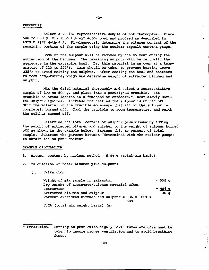
-2-
PROCEDURE
Select a 20 lb. representative sample of hot Thermopave. Place 500 to 800 g. mix into the extractor bowl and proceed as described in ASTM D 2172 Method A. Simulaaneously determine the bitumen content of the remaining portion of the sample using the nuclear asphalt content gauge.
Some of the sulphur will be removed by the solvent during the extraction of the bitumen. The remaining sulphur will be left with the aggregate in the extractor bowl. Dry this material in an oven at a temperature of 210 to 220°F. Care should be taken to prevent heating above 235°F to avoid melting the sulphur. After cooling the bowl and contents to room temperature, weigh and determine weight of extracted bitumen and sulphur.
Mix the dried material thoroughly and select a representative sample of 100 to 500 g. and place into a preweighed crucible. Set crucible on stand located in a fumehood or outdoors.* Heat slowly until the sulphur ignites. Increase the heat as the sulphur is burned off. Stir the material in the crucible co ensure that all of the sulphur is completely burned off. Cool the crucible to room temperature, and weigh the sulphur burned off.
Determine the total content of sulphur plusbituaanby adding the weight of extracted bitumen and sulphur to the weight of sulphur burned off as shown in the example below. Express this as percent of total sample. Subtract the percent bitumen (determined with the nuclear gauge) to obtain the sulphur content.
EXAMPLE CALCULATION
1. Bitumen content by nuclear method = 6.0% w (total mix basis)
2. Calculation of total bitumen plus sulphur:
(i) Extraction
Weight of mix sample in extractor Dry weight of aggregate/sulphur material after extraction Extracted bitumen and sulphur Percent extracted bitumen and sulphur • 36 x 100\ •
500 7.2\ (total mix weight basis) (a)
z 500 g
= 464 g 36 g
* Precaution: Burning sulphur emits highly toxic fumes and care must be taken to insure proper ventilation and to avoid breathing fumes.
104 •
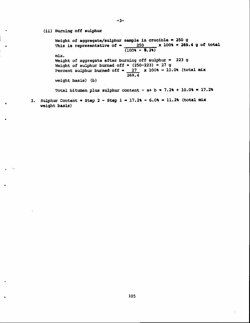
..
-3-
(ii) Burning off sulphur
Weight of aggregate/sulphur sample in crucible • 250 9 This is representative of • 250 x 100' • 269.4 q ot total
(100, - 1.2,) mix. Weight of aggregate after burning off sulphur • 223 g Weight of sulphur burned off • (250-223) = 27 g Percent sulphur burned off = 27 x 100\ = 10.0\ (total mix
269.4 weight basis) (b)
Total bitumen plus sulphur content - a+ b • 7.2, + 10.0' • 17.2'
3. Sulphur Content • Step 2 - Step 1 • 17.2\ - 6.0% • 11.2' (total mix weight basis)
105
Figure Bl. Ignition of S-A-S Mixture To Determine Binder Content
106
..
•
Appendix C
Shell Canada Limited
Oakville Research Centre
TENTATIVE METHOD OF TEST FOR SLUMP OF THERMOPAVE~ MIX
SCOPE
This test method outlines the procedure to be used for determining the slump of Thermopave mix. It is a modified version of ASTM Test Method c 143-69.
APPARATUS
In addition to apparatus specified by ASTM C 143-69, the following equipment is required: oven with capacity to 350°F, high temperature resistant grease (eg. Dow Corning Silicone Grease No. 970 V), thermometer (200 to 350°F range), metal scoop.
PROCEDURE
Preheat the oven to 300°F ± 5°F. Clean and grease thoroughly the interior of the slump mold. The thickness of the grease film should not exceed 0. 5 nun. Heat the mold, tamping rod and scoop in the oven for at least one-half hour before the test.
Obtain a 40 lb. sample of hot(270 to 300°F) Thermopave mix. Remove the mold from the oven, place it on a firm surface and hold it firmly while filling by standing on the two foot rests. Fill the mold completely using the hot scoop, heaping the mix above the top of the mould. Rod the mix rapidly 25 times to the full depth of the mold using the hot tamping rod and distributing the strokes uniformly across the surface of the mold. Strike off the excess mix with a stroking and rolling motion of the tamping rod. Separate the mold from the mix by raising the mold carefully in a vertical direction. Measure the slump to the nearest 0. 5 inch. Measure the temperature at the centre of the specimen as quickly as possible.
~ Shell Canada Limited Registered Trademark for Aggregate/Asphalt/Sulphur Mixes.
107

•
..
...
•
•
Appendix D
Shell Canada Limited
Oakville Research Centre
'l'BN!l'ATIVB METHOD FOR PREPARATION OF THp!lgPAVB-~ SPECIMENS !'OJ. MARSHALL TESTING
Scope: This method entails the fabrication of specimens, using sand,
asphalt and sulphur. A mixture of sand and asphalt is first made, and then
hot, molten sulphur is added to this mix.
Equipment:
(a) Mechanical mixer (variable speed) 4 qt. capacity.
(b) Marshall Mould Assembly as per diagram.
(c) l small and 1 large scoop.
(d) 2 large spatulas.
(e) Thermometer dial type +50 to 450°F metal stem.
(f) Oven for heating sand, moulds, mixing bowl, stirrer and asphalt.
(g) Hot plate for heating Marshall hammer and spatula.
(h) Deep fryer for melting flour sulphur •
(i) Marshall hammer.
(j) Balance 5 kgs. capacity sensitive to 1 grm.
(k) Gloves for handling hot equipment.
(1) Ventilation system.
{m) Flour sulphur.
(n) High temperature grease, or some suitable release agent.
Pre~arations:
lands Dry aand and keep in oven at 300°F + 5°F. Avoid lumps of
material due to drying of wet sand.
Qt Shell Canada Limited Trademark for Aggregate/Aaphalt/Sulphur Mixea
IC3
- 2 -
Asphalt: Keep one gallon of asphalt in an oven at Joo•r + s•r.
Sulphur: Weigh out quantity of sulphur to be used in mix design and
put in deep fryer, heat to 275-290°F. Viscosity of sulphur
would undergo changes if overheated.
Mould Assembly, Marshall Hammer, Mixing Bowl and Stirrer
Thoroughly clean, place mould assembly, mixing bowl and
stirrer in oven at 300°F for at least one hour prior to moulding
specimens. Clean Marshall hammer, can be heated on a hot plate, or any
suitable heat source.
Number of Specimens
If only Marshall stability is required, at least four and
preferably six specimens should be made.
Mix Preparation
Weigh predetermined quantity of sand, calculated on batch size
and mix design. (1100 grms. per specimen). Sand temperature should be
300°F + 5°F. Put weighed sand into heated mixing bowl and stir at lowest
speed for about 3-5 sees. Form a crater in the sand and weigh the required
amount of asphalt cement into the sand. Using the lowest speed on the
mixer, switch on and off in quick successions to allow some dispersion of
asphalt into the sand. This prevents spilling of asphalt from bowl,
when higher speed is being employed. This procedure should take about 5
sees. Select a suitable higher mixer speed and mix thoroughly to yield a
mixture having a uniform distribution of asphalt throughout. This should
109
•
..,
•
•
- 3 -
be accomplished in 30-35 sees. of mixing. Pour in moleen sulphur
275-290°F and repeat mixing procedure as for sand and asphalt, total
mixing time should not exceed 65 sees. Measure and record mix temperature.
Moulding and Compaction Procedure:
Put a very thin film of grease or suitable release agent in
hot moulds. Half fill mould with hot mix, and using small scoop, press
vigorously around the perimeter and in the centre, repeat until mould is
filled to 1/8" below the top of mould collar. Slightly grease the heated
face of the Marshall hammer, and apply two blows to each specimen on one
side only, remove collar, trim and smooth off with hot spatula.
Recommendations and Precautions:
Sulphur must not be overheated, 275-290°F and sand temperature
should not exceed 3l0°F. This may cause the evolution of harmful fumes.
Mixing should be done in a well-ventilated area, preferably with some
expel air system. Initially, two people should be available in the
mould procedure, until the method is perfeetlyyunderstood.
All equipment used in moulding samples must be hot, and
thoroughly cleaned before reheating. Avoid putting cooled mix (crusted)
into mould1 mix should not be reheated, but if it becomes necessary to
keep mix hot during mixing and moulding specimens, a heating mantle can
be employed.
110