sales engineer alpha technologies - scte...
TRANSCRIPT

1
Tony Castro Sales Engineer
Alpha Technologies
[email protected] office: 909-227-1481
www.alpha.com
2
Power
Maintenance
System Reliability
3
Power
What are the different UPS’s?
Why is this one heavy?
How does this one work?
4
Power: Types of UPS’s
Standby UPS
Line-Interactive UPS
Double Conversion On-Line
Standby Ferro UPS
5
Power
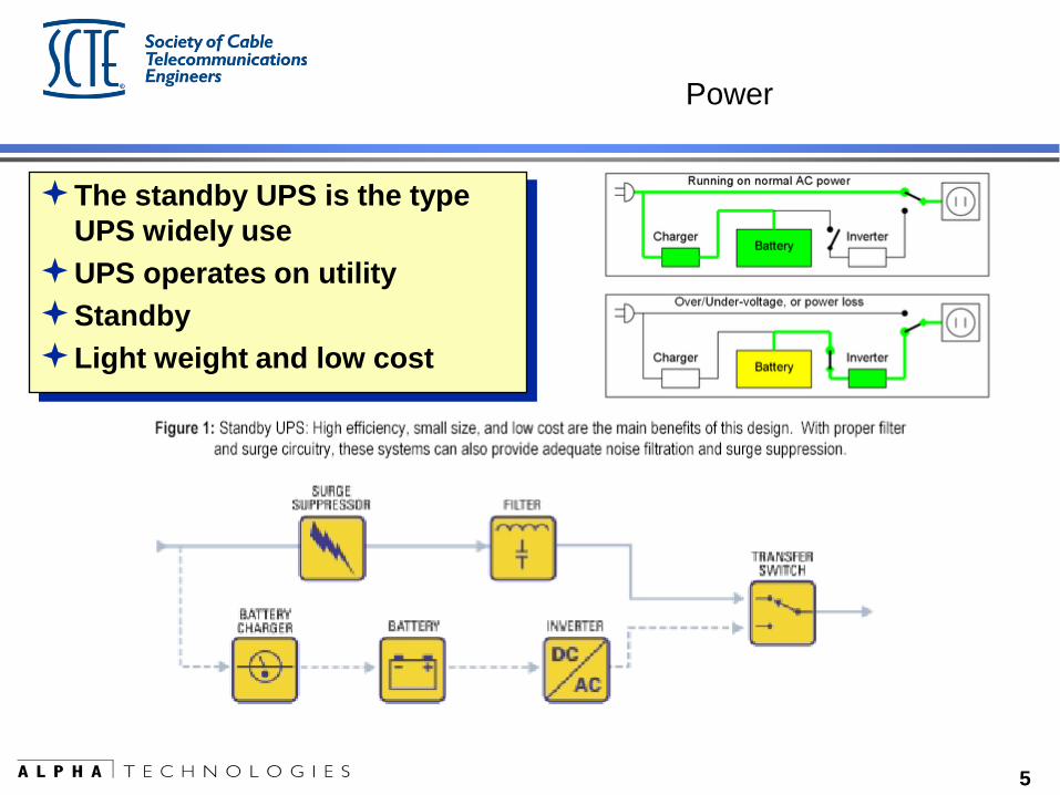
The standby UPS is the type
UPS widely use
UPS operates on utility
Standby
Light weight and low cost
6
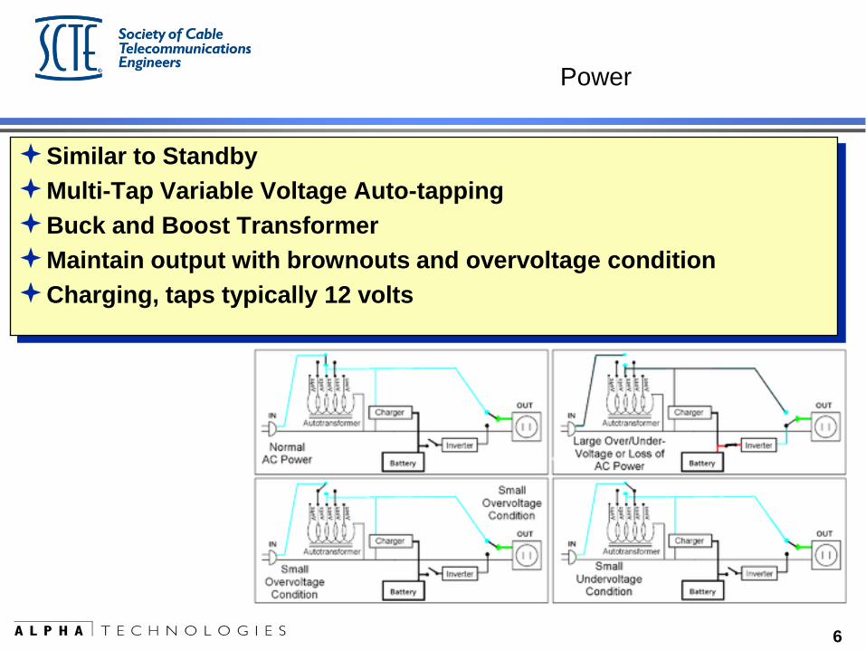
Power
Similar to Standby
Multi-Tap Variable Voltage Auto-tapping
Buck and Boost Transformer
Maintain output with brownouts and overvoltage condition
Charging, taps typically 12 volts
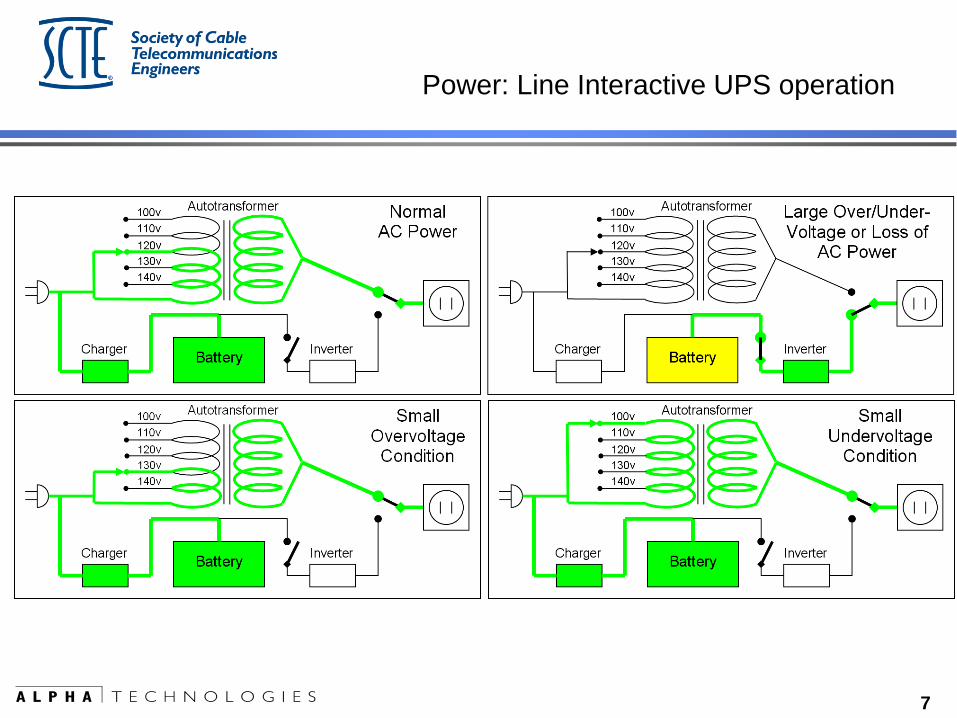
7
Power: Line Interactive UPS operation
8
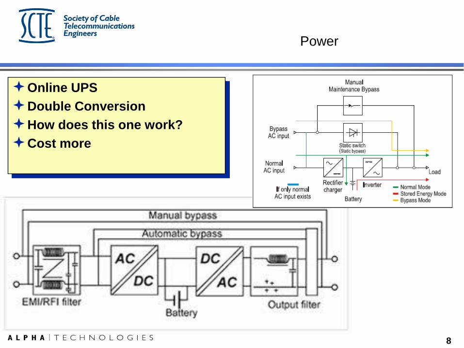
Power
Online UPS
Double Conversion
How does this one work?
Cost more
9
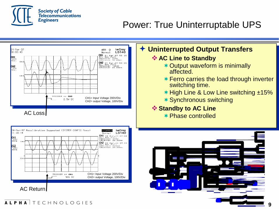
Power: True Uninterruptable UPS
Uninterrupted Output Transfers
AC Line to Standby
Output waveform is minimally affected.
Ferro carries the load through inverter switching time.
High Line & Low Line switching ±15%
Synchronous switching
Standby to AC Line
Phase controlled
CH1= Input Voltage 200V/Div
CH2= output Voltage, 100V/Div
CH1= Input Voltage 200V/Div
CH2= output Voltage, 100V/Div
AC Loss
AC Return
PIM Option
A C O u t p u t 1
A C O u t p u t 2
A C O u t p u t
K1
RV1
RV3
RV2
A C O u t p u t
B LK
WH T
O u t p u t S elec t90VAC
60VAC
75VACB LK
WH T
R EDB LK
.
C1
Relay
Tr an s for m er
Inverter
AC L ine Detector
and
Control Logic
Circuits
Batteries
R em ot eTem p er at u r eS en s or
USM2 Card
C a r dC o m m u n ica t io n sO p t io n a l
P lu g -in M od u le A ssemb ly
Control
O u t p u t Fu s e
R E D
B LKB LK
R E D
A C 2
A C 1
B r eakerC ir c u itB at t er y
( + )
( - )
120VAC Jum pe r240VAC Jum pe r
I n p u t S elec t
10
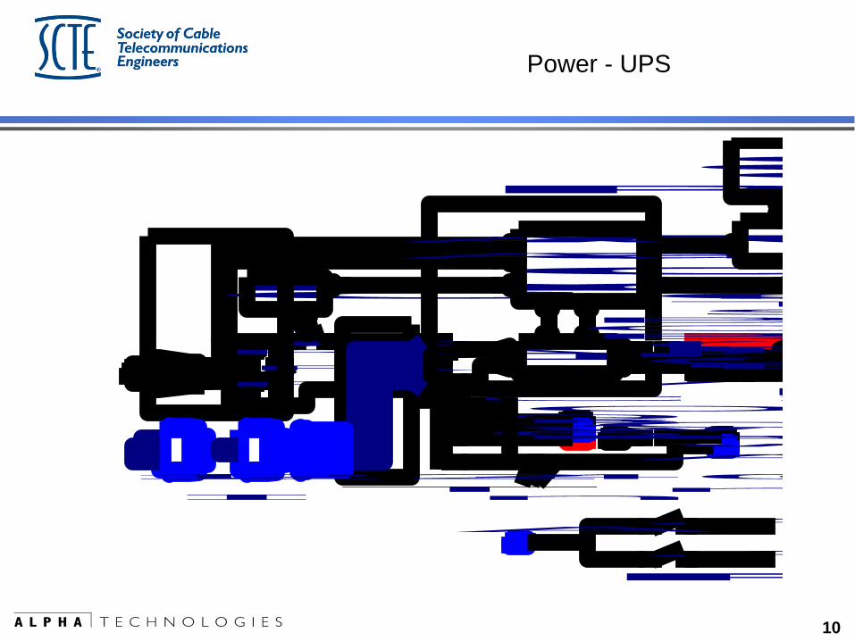
Power - UPS
PIM Option
A C O u t p u t 1
A C O u t p u t 2
A C O u t p u t
K1
RV1
RV3
RV2
A C O u t p u t
B LK
WH T
O u t p u t S elec t90VAC
60VAC
75VACB LK
WH T
R EDB LK
.
C1
Relay
Tr an s for m er
Inverter
AC L ine Detector
and
Control Logic
Circuits
Batteries
R em ot eTem p er at u r eS en s or
USM2 Card
C a r dC o m m u n ica t io n sO p t io n a l
P lu g -in M od u le A ssemb ly
Control
O u t p u t Fu s e
R E D
B LKB LK
R E D
A C 2
A C 1
B r eakerC ir c u itB at t er y
( + )
( - )
120VAC Jum pe r240VAC Jum pe r
I n p u t S elec t
11
Why is it we never have time to do
Preventative Maintenance,
yet we can always find time to
fix it after it breaks?
12
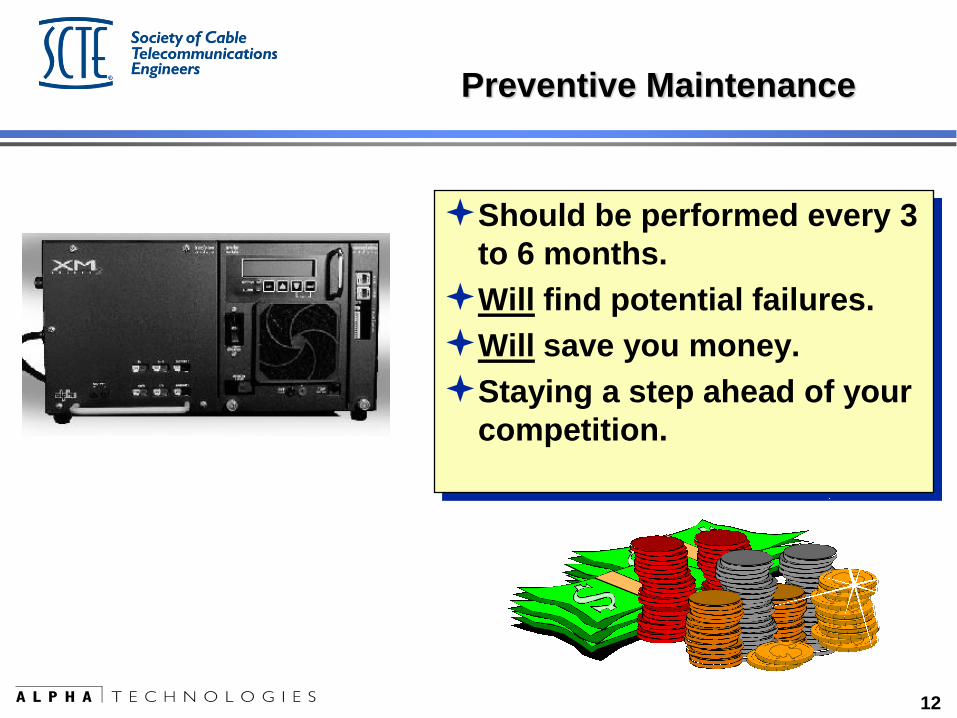
Preventive Maintenance
Should be performed every 3
to 6 months.
Will find potential failures.
Will save you money.
Staying a step ahead of your
competition.
13
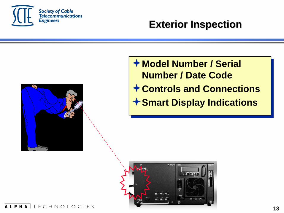
Exterior Inspection
Model Number / Serial
Number / Date Code
Controls and Connections
Smart Display Indications
14
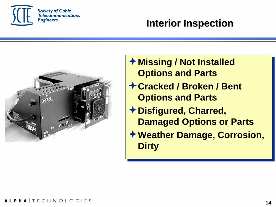
Interior Inspection
Missing / Not Installed
Options and Parts
Cracked / Broken / Bent
Options and Parts
Disfigured, Charred,
Damaged Options or Parts
Weather Damage, Corrosion,
Dirty
15
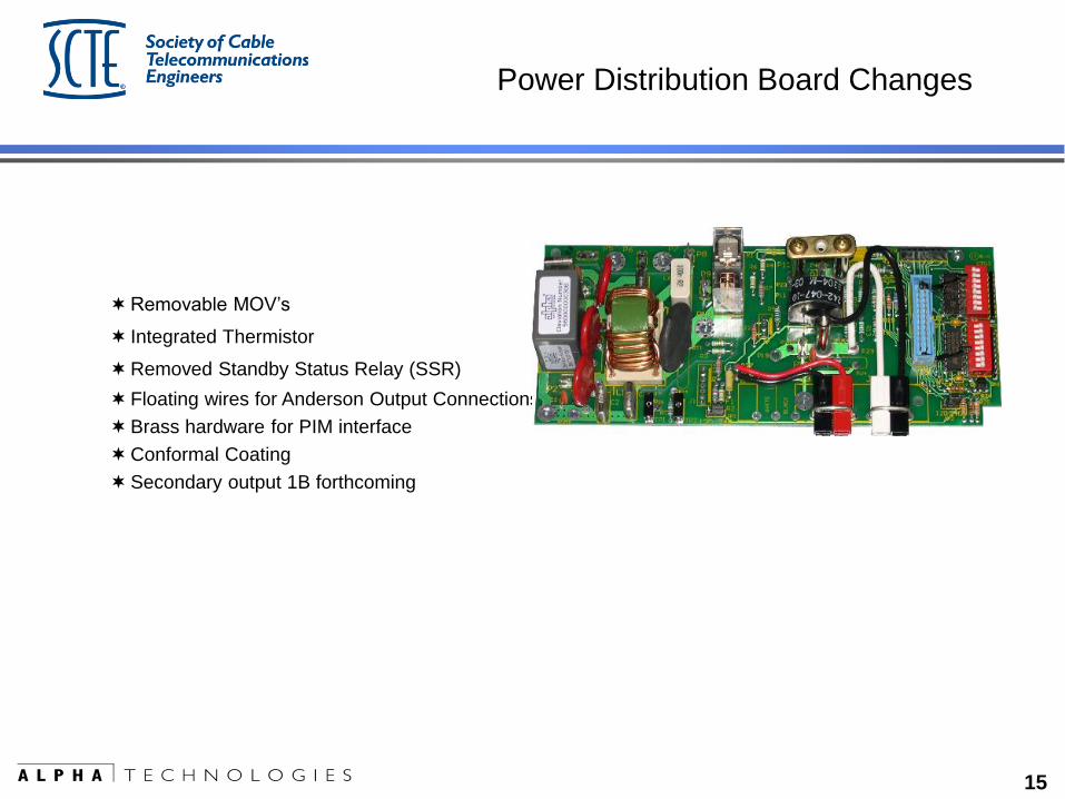
Power Distribution Board Changes
Removable MOV’s
Integrated Thermistor
Removed Standby Status Relay (SSR)
Floating wires for Anderson Output Connections
Brass hardware for PIM interface
Conformal Coating
Secondary output 1B forthcoming
16
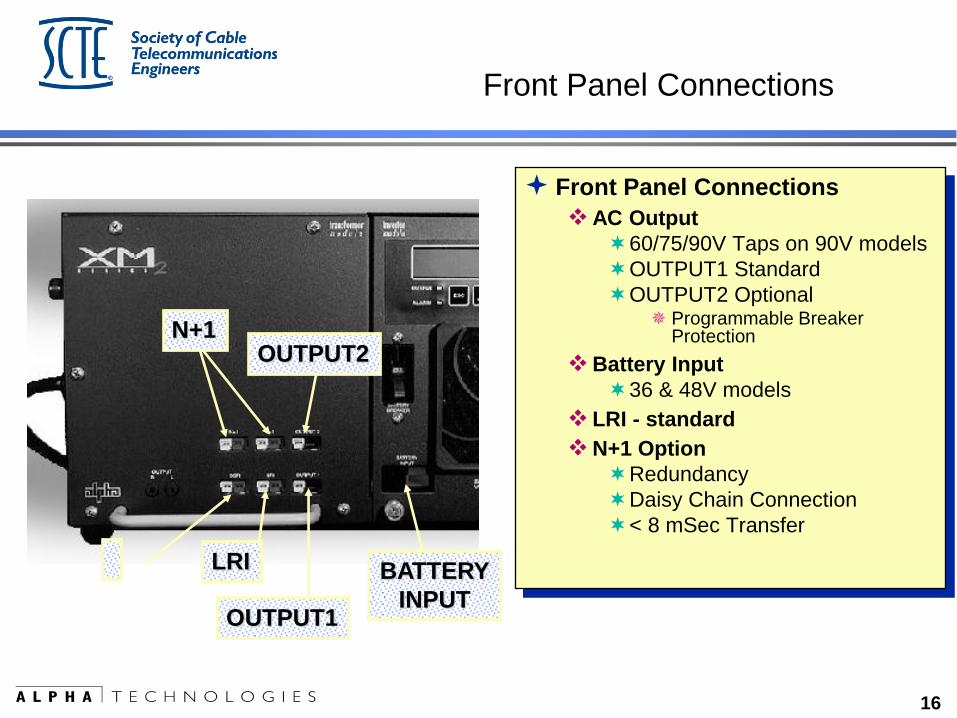
Front Panel Connections
Front Panel Connections
AC Output
60/75/90V Taps on 90V models
OUTPUT1 Standard
OUTPUT2 Optional Programmable Breaker
Protection
Battery Input
36 & 48V models
LRI - standard
N+1 Option
Redundancy
Daisy Chain Connection
< 8 mSec Transfer
OUTPUT2 N+1
OUTPUT1
LRI BATTERY
INPUT
17
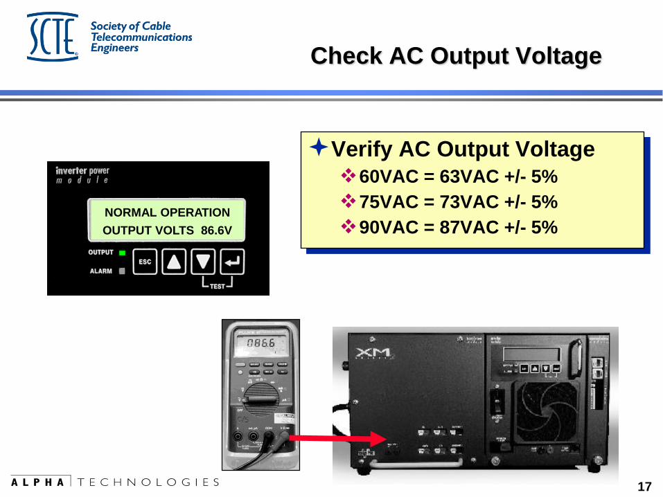
Check AC Output Voltage
Verify AC Output Voltage
60VAC = 63VAC +/- 5%
75VAC = 73VAC +/- 5%
90VAC = 87VAC +/- 5% NORMAL OPERATION
OUTPUT VOLTS 86.6V
18
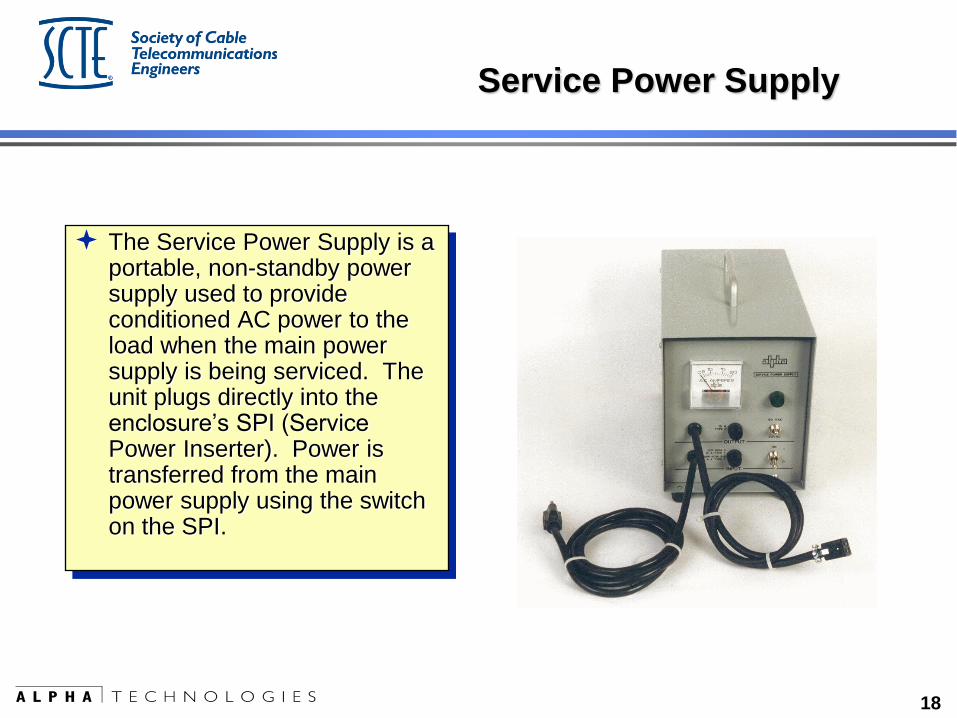
Service Power Supply
The Service Power Supply is a portable, non-standby power supply used to provide conditioned AC power to the load when the main power supply is being serviced. The unit plugs directly into the enclosure’s SPI (Service Power Inserter). Power is transferred from the main power supply using the switch on the SPI.
19
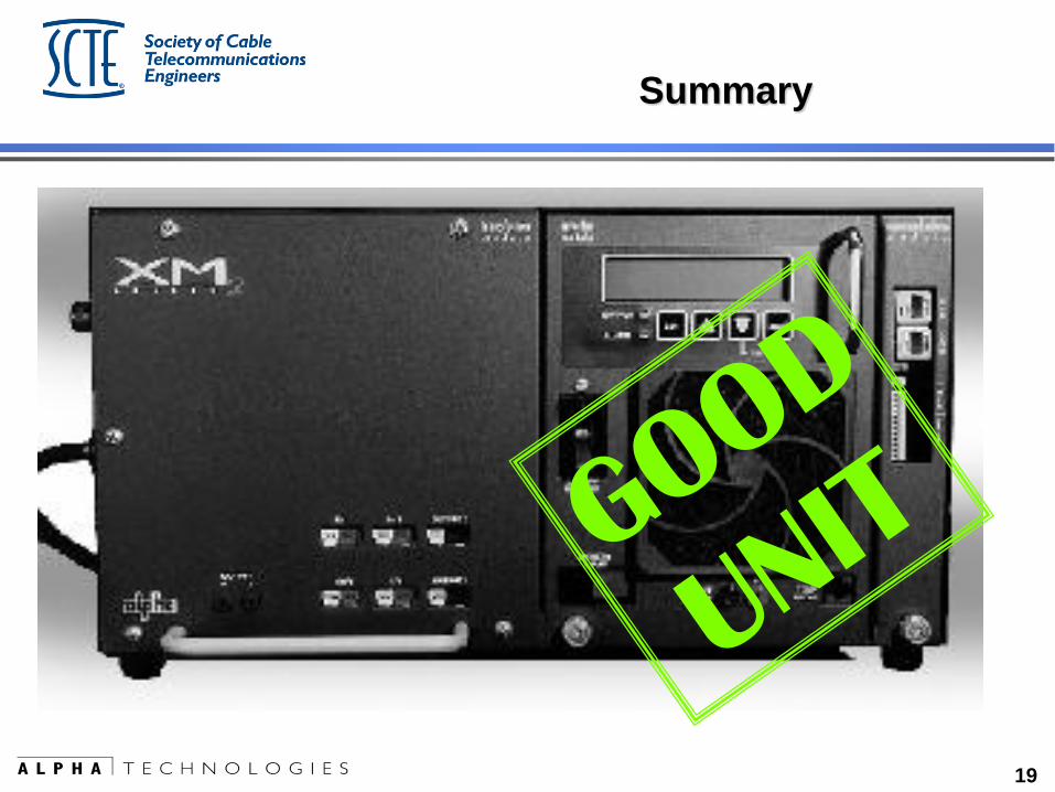
Summary
20
Planning for
SYSTEM RELIABLITY
21
Make the PLAN
WHAT are the goals?
System Reliability =
Happy Customers =
More $$$$$$
(and did I mention it makes you look good too ?)

22
Make the PLAN
HOW do I justify the goals?
Planned time and expense
rather than unplanned panic response
to the crisis of the moment.
23
Make the PLAN
WHO is going to do it?
Do they have the proper training?
Are they empowered to get the job done?
24
Make the PLAN
WHAT is required to accomplish the plan?
Equipment, tools, spare parts
25
Make the PLAN
WHAT data are you going to collect?
And more importantly, what are you going to do
with the data?
Use the data to prevent problems before they
happen.

26
Something to include
in the plan
27
Batteries
28
Often the power supply
system is only as reliable
as the
condition of the
batteries !
29
Battery “Issues”
Despite improvements in battery chemistry and manufacturing, batteries still age
at unique and individual rates, and…
All broadband power supplies discharge and re-charge the battery system based
on total string data, not individual battery data.
Each battery does not receive an ideal charge – some are overcharged, some are
undercharged.
One bad battery can kill the entire string - due to charging imbalance.
A weak battery reduces the actual system run time.

30
Battery Testing
HOW do you know when you have a BAD battery?
Voltage test?
Power supply self-test?
Your supply does have a self-test function, doesn’t it?
Short-duration / high-rate load test?
Conductance or Impedance testing?
How much money is being wasted?
31
Battery Testing
Conductance or Impedance testing provides a safe and
reliable method for evaluating batteries.
Injects an AC signal into the battery string.
Can be done without disconnecting the battery.
Reduces personnel risk.
Typically takes about 7-10 seconds per battery.
32
Battery Testing
Work smarter, not harder.
Easier tasks translate into tasks more likely to be completed,
and completed correctly.
33
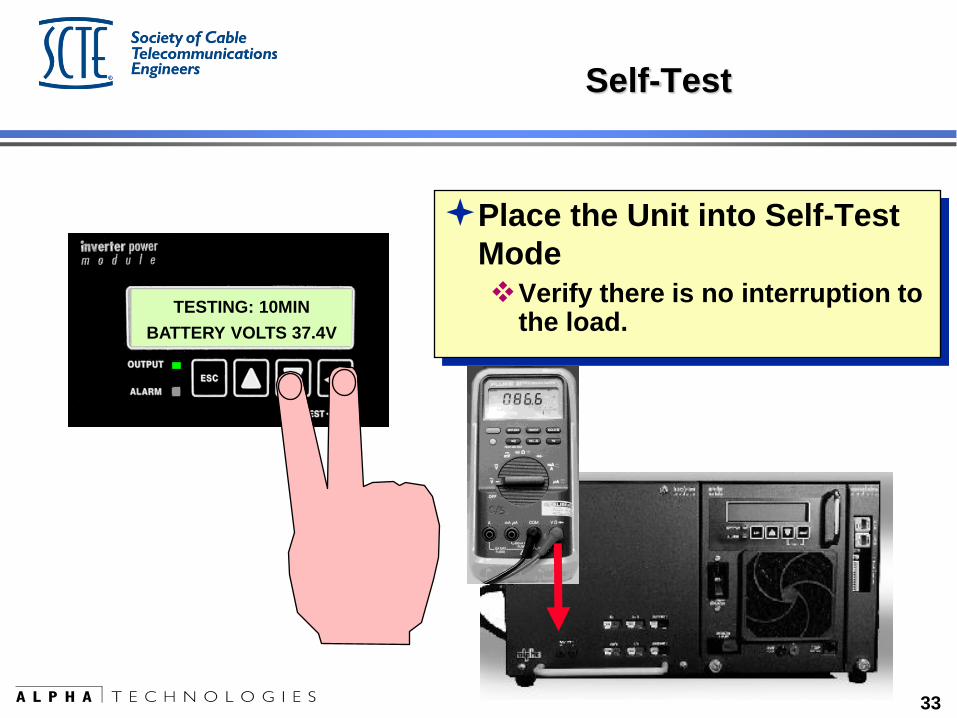
Self-Test
Place the Unit into Self-Test
Mode
Verify there is no interruption to the load.
TESTING: 10MIN
BATTERY VOLTS 37.4V
34
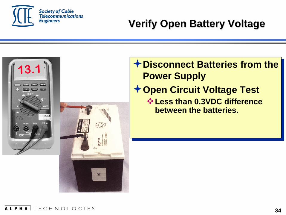
Verify Open Battery Voltage
Disconnect Batteries from the
Power Supply
Open Circuit Voltage Test
Less than 0.3VDC difference between the batteries.
35
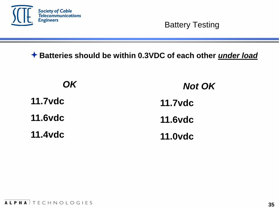
Battery Testing
Batteries should be within 0.3VDC of each other under load
OK
11.7vdc
11.6vdc
11.4vdc
Not OK
11.7vdc
11.6vdc
11.0vdc
36
Battery “Issues”
Most MSOs would prefer to swap-out only the one weak or failed battery,
not the entire string.
Cost of unnecessary labor to swap-out perfectly good batteries.
Lost value of good batteries changed before end of life.
37
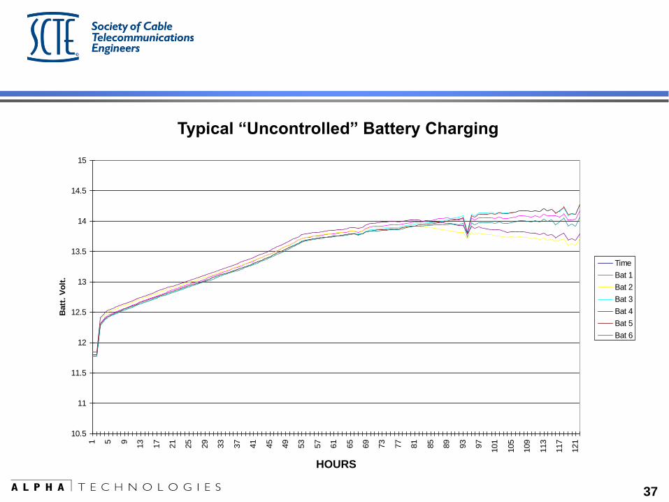
Discharge / Recharge 6ea 165GXL
10.5
11
11.5
12
12.5
13
13.5
14
14.5
15
1 5 9
13
17
21
25
29
33
37
41
45
49
53
57
61
65
69
73
77
81
85
89
93
97
101
105
109
113
117
121
Time
Batt
. V
olt
.
Time
Bat 1
Bat 2
Bat 3
Bat 4
Bat 5
Bat 6
Enables the battery string to maintain its capacity over life.
HOURS
Typical “Uncontrolled” Battery Charging
38
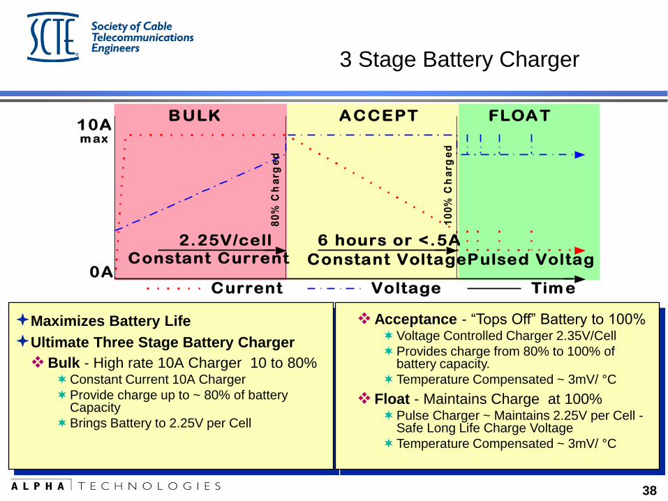
3 Stage Battery Charger
Maximizes Battery Life
Ultimate Three Stage Battery Charger
Bulk - High rate 10A Charger 10 to 80% Constant Current 10A Charger
Provide charge up to ~ 80% of battery Capacity
Brings Battery to 2.25V per Cell
Acceptance - “Tops Off” Battery to 100% Voltage Controlled Charger 2.35V/Cell
Provides charge from 80% to 100% of battery capacity.
Temperature Compensated ~ 3mV/ °C
Float - Maintains Charge at 100% Pulse Charger ~ Maintains 2.25V per Cell -
Safe Long Life Charge Voltage
Temperature Compensated ~ 3mV/ °C
0A
10A
Constant Current Constant VoltagePulsed Voltage
m ax
6 hours or <.5A2.25V/cell
A CCEPT FLOA T
Current Voltage Tim e
B ULK
10
0%
Ch
ar
ge
d
80
% C
ha
rg
ed
39
So what’s the solution?
Battery Balancer
A device to increase battery life by maintaining each battery fully charged.
The Battery Balancer keeps the charge on each battery identical.
As if we had an individual battery charger for each battery – effectively charging
each battery instead of the entire string.
40
Benefits?
As one battery in a string starts to go bad, the other batteries in the string will
typically be under or over charged, eventually leading to multiple premature
failures.
The battery balancer protects the remaining good batteries from damage
by the weak battery.
The battery balancer allows the replacement of just one battery in a
string, regardless of age.
The battery balancer insures that maximum battery capacity is provided
over the life of the battery.
41
Battery inspection
Clean Terminals
Correct Hardware Stack-up
Terminal Protectant
42
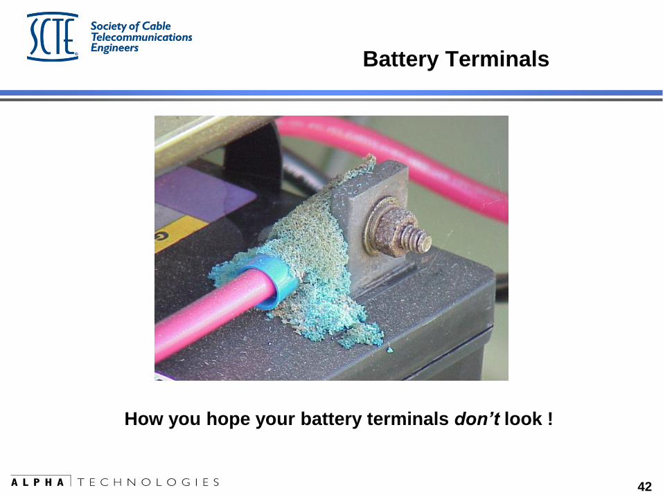
Battery Terminals
How you hope your battery terminals don’t look !
43
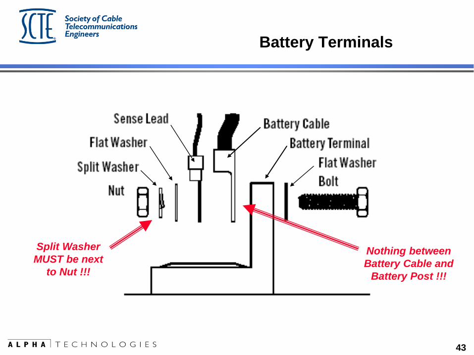
Battery Terminals
Nothing between
Battery Cable and
Battery Post !!!
Split Washer
MUST be next
to Nut !!!
44
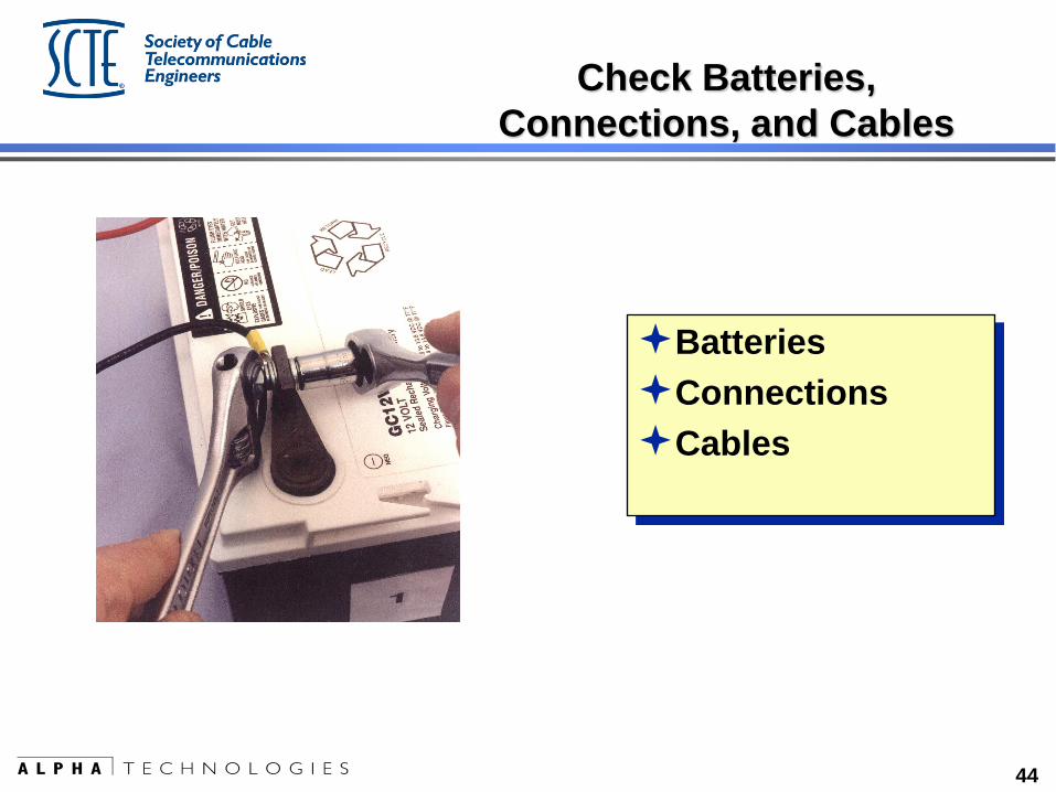
Batteries
Connections
Cables
Check Batteries,
Connections, and Cables
45
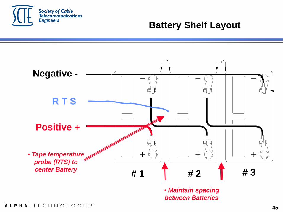
Battery Shelf Layout
# 1 # 2 # 3
Positive +
Negative -
R T S
• Tape temperature
probe (RTS) to
center Battery
• Maintain spacing
between Batteries
46
Improvements in
Status Monitoring
47
What comes after Preventative Maintenance?
Status Monitoring
NOT intended to be a replacement for
Preventative Maintenance
48
Today, the typical power supply installation uses an
embedded transponder or external status monitoring
transponder.
History reflects issues with the installation and installation
reliability.
49
Solution?
The current generation of power supplies now include the
transponder in the power supply.
Simple “F” connection on the front of the supply
Reduces the “rats nest” of sensing and interconnect cabling
Provides physical protection to the transponder
Provides a single ground reference
Powered by the power supply logic, not the batteries
50
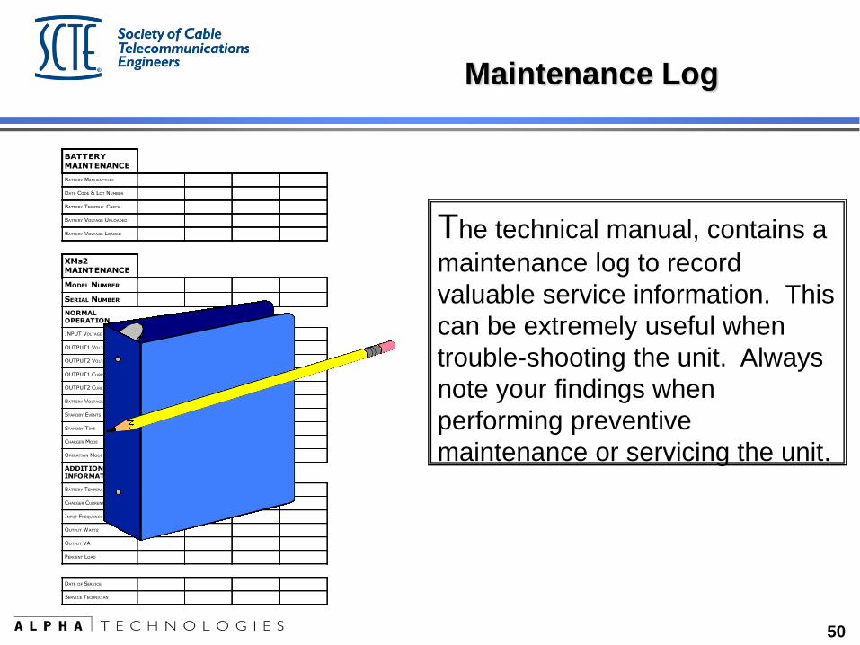
The technical manual, contains a
maintenance log to record
valuable service information. This
can be extremely useful when
trouble-shooting the unit. Always
note your findings when
performing preventive
maintenance or servicing the unit.
BATTERYMAINTENANCE
BATTERY MANUFACTURE
DATE CODE & LOT NUMBER
BATTERY TERMINAL CHECK
BATTERY VOLTAGE UNLOADED
BATTERY VOLTAGE LOADED
XMs2MAINTENANCE
MODEL NUMBER
SERIAL NUMBER
NORMALOPERATION
INPUT VOLTAGE
OUTPUT1 VOLTAGE
OUTPUT2 VOLTAGE
OUTPUT1 CURRENT
OUTPUT2 CURENT
BATTERY VOLTAGE
STANDBY EVENTS
STANDBY TIME
CHARGER MODE
OPERATION MODE
ADDITIONALINFORMATION
BATTERY TEMPERATURE
CHARGER CURRENT
INPUT FREQUENCY
OUTPUT WATTS
OUTPUT VA
PERCENT LOAD
DATE OF SERVICE
SERVICE TECHNICIAN
Maintenance Log

51
Questions ????
Comments ???
Ugly remarks ??
52
Thanks for your time !!!