saab 900 automatic to manual conversiona hydraulic floor jack four good jack stands. always use jack...
TRANSCRIPT
This Document serves both as a record of a project on a 1984 Saab 900, and asa reference for do-it-yourselfers who wish to convert from automatic tomanual shift. These notes apply only to the 1979-1993 Saab 900 including the1994 convertible. The project these notes are based on was completed inDecember 1998 and posted on the internet in February 1999.http://www.redstone.net/mvj/900convert
SAAB 900
Automatic to Manual Conversion
written by Mark Jeter
Getting Started
Since, it is necessary to remove the entire engine and transmission from a 900 inorder to replace it's transmission, a certain amount of equipment is necessary.What follows is a list of the bare minimum required to complete this project.
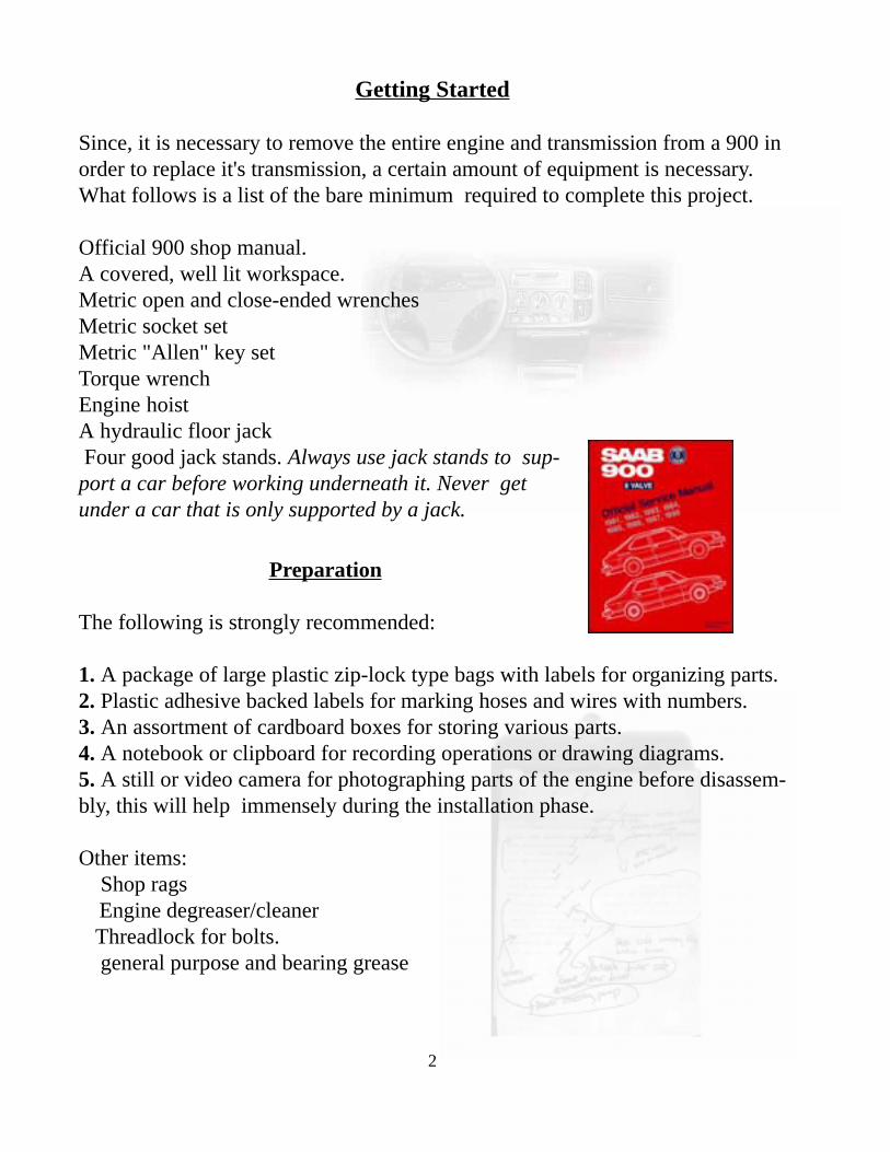
Official 900 shop manual.A covered, well lit workspace.Metric open and close-ended wrenchesMetric socket setMetric "Allen" key setTorque wrenchEngine hoistA hydraulic floor jack Four good jack stands. Always use jack stands to sup-port a car before working underneath it. Never getunder a car that is only supported by a jack.
Preparation
The following is strongly recommended:
1. A package of large plastic zip-lock type bags with labels for organizing parts.2. Plastic adhesive backed labels for marking hoses and wires with numbers.3. An assortment of cardboard boxes for storing various parts.4. A notebook or clipboard for recording operations or drawing diagrams.5. A still or video camera for photographing parts of the engine before disassem-bly, this will help immensely during the installation phase.
Other items: Shop rags Engine degreaser/cleaner Threadlock for bolts. general purpose and bearing grease
2
Project Outline
I. Remove engine/automatic transmission from car.
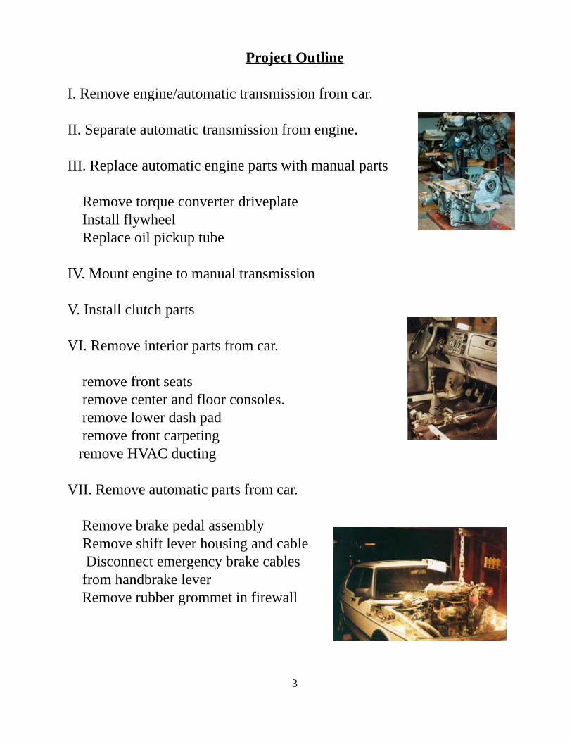
II. Separate automatic transmission from engine.
III. Replace automatic engine parts with manual parts
Remove torque converter driveplate Install flywheel Replace oil pickup tube
IV. Mount engine to manual transmission
V. Install clutch parts
VI. Remove interior parts from car.
remove front seats remove center and floor consoles. remove lower dash pad remove front carpeting remove HVAC ducting
VII. Remove automatic parts from car.
Remove brake pedal assembly Remove shift lever housing and cable Disconnect emergency brake cables from handbrake lever Remove rubber grommet in firewall
3
VIII. Install manual parts in car.
Install brake/clutch pedal assembly. Install clutch master cylinder Install clutch hydraulic line Replace lower dash padding
IX. Swap shift lever housing parts
ignition switch key cylinder
X. Install engine/transmission into car.
bolt in engine mounts seat driveshafts into transmission reattach lower balljoints
XI. Install manual shift lever housing and selector rod.
thread handbrake cables through grommet. install taper pin in selector shaft. adjust shift lever and check operation. reconnect ignition switch wires.
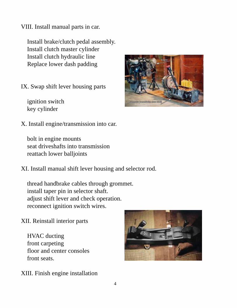
XII. Reinstall interior parts
HVAC ducting front carpeting floor and center consoles front seats.
XIII. Finish engine installation
4
Parts Checklist
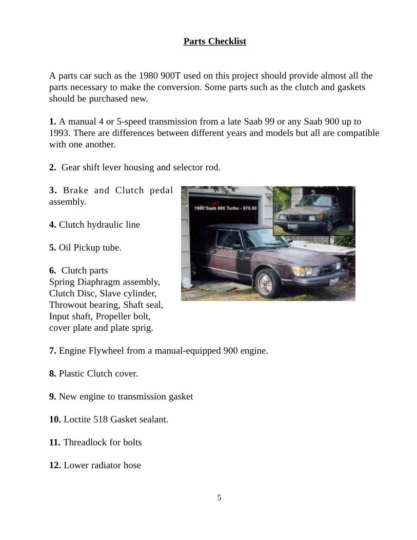
A parts car such as the 1980 900T used on this project should provide almost all theparts necessary to make the conversion. Some parts such as the clutch and gasketsshould be purchased new.
1. A manual 4 or 5-speed transmission from a late Saab 99 or any Saab 900 up to1993. There are differences between different years and models but all are compatiblewith one another.
2. Gear shift lever housing and selector rod.
3. Brake and Clutch pedalassembly.
4. Clutch hydraulic line
5. Oil Pickup tube.
6. Clutch partsSpring Diaphragm assembly,Clutch Disc, Slave cylinder,Throwout bearing, Shaft seal,Input shaft, Propeller bolt,cover plate and plate sprig.
7. Engine Flywheel from a manual-equipped 900 engine.
8. Plastic Clutch cover.
9. New engine to transmission gasket
10. Loctite 518 Gasket sealant.
11. Threadlock for bolts
12. Lower radiator hose
5
Manual Transmission Issues
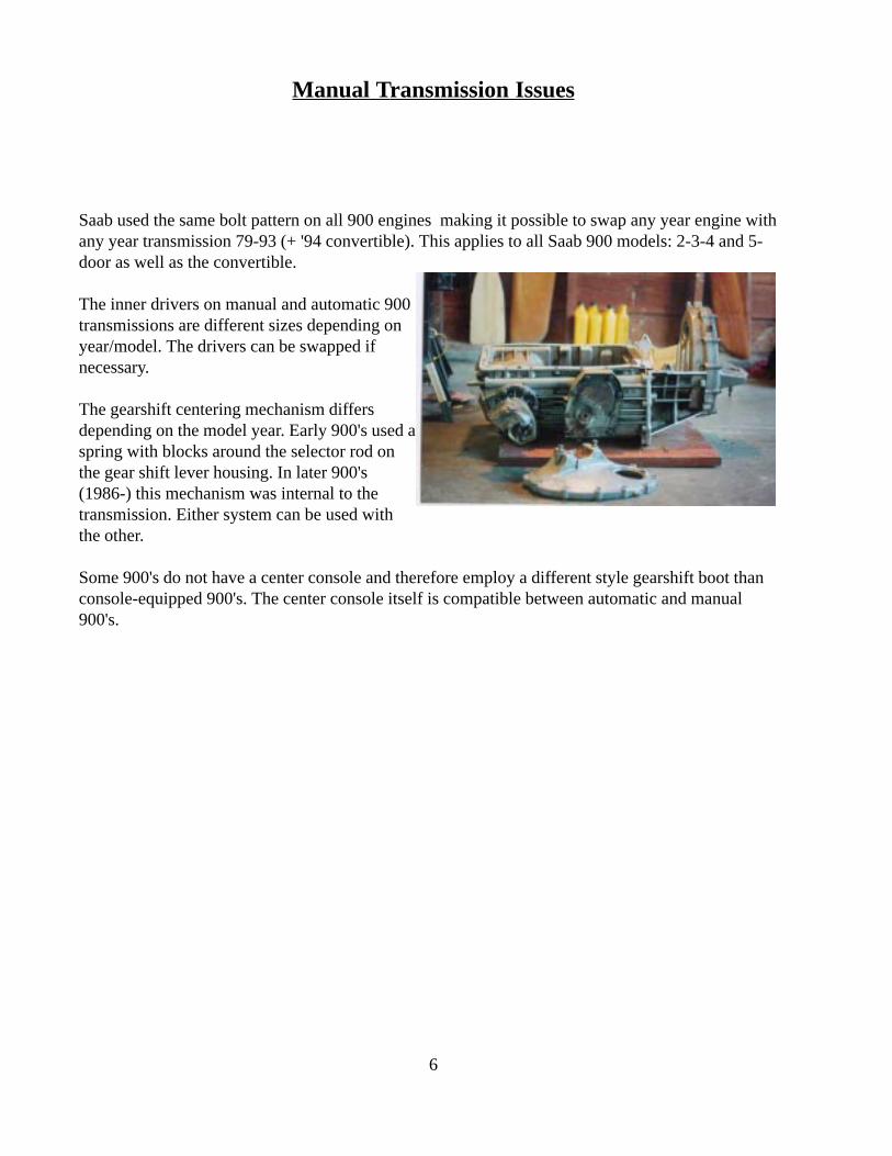
Saab used the same bolt pattern on all 900 engines making it possible to swap any year engine withany year transmission 79-93 (+ '94 convertible). This applies to all Saab 900 models: 2-3-4 and 5-door as well as the convertible.
The inner drivers on manual and automatic 900transmissions are different sizes depending onyear/model. The drivers can be swapped ifnecessary.
The gearshift centering mechanism differsdepending on the model year. Early 900's used aspring with blocks around the selector rod onthe gear shift lever housing. In later 900's(1986-) this mechanism was internal to thetransmission. Either system can be used withthe other.
Some 900's do not have a center console and therefore employ a different style gearshift boot thanconsole-equipped 900's. The center console itself is compatible between automatic and manual900's.
6
Gearshift Lever and Selector Rod
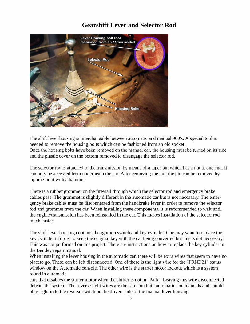
The shift lever housing is interchangable between automatic and manual 900's. A special tool isneeded to remove the housing bolts which can be fashioned from an old socket.Once the housing bolts have been removed on the manual car, the housing must be turned on its sideand the plastic cover on the bottom removed to disengage the selector rod.
The selector rod is attached to the transmission by means of a taper pin which has a nut at one end. Itcan only be accessed from underneath the car. After removing the nut, the pin can be removed bytapping on it with a hammer.
There is a rubber grommet on the firewall through which the selector rod and emergency brakecables pass. The grommet is slightly different in the automatic car but is not neccasary. The emer-gency brake cables must be disconnected from the handbrake lever in order to remove the selectorrod and grommet from the car. When installing these components, it is recommended to wait untilthe engine/transmission has been reinstalled in the car. This makes installation of the selector rodmuch easier.
The shift lever housing contains the ignition switch and key cylinder. One may want to replace thekey cylinder in order to keep the original key with the car being converted but this is not neccesary.This was not performed on this project. There are instructions on how to replace the key cylinder inthe Bentley repair manual.When installing the lever housing in the automatic car, there will be extra wires that seem to have noplaceto go. These can be left disconnected. One of these is the light wire for the "PRND21" statuswindow on the Automatic console. The other wire is the starter motor lockout which is a systemfound in automaticcars that disables the starter motor when the shifter is not in "Park". Leaving this wire disconnecteddefeats the system. The reverse light wires are the same on both automatic and manuals and shouldplug right in to the reverse switch on the drivers side of the manual lever housing
7
Brake/Clutch pedal assembly.
It is recommended to first remove the engine/transmission before starting this part of the project as itmakes much of this work much easier.
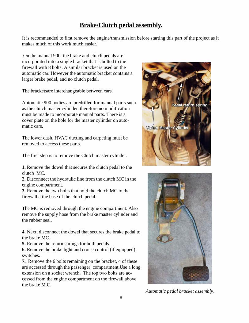
On the manual 900, the brake and clutch pedals areincorporated into a single bracket that is bolted to thefirewall with 8 bolts. A similar bracket is used on theautomatic car. However the automatic bracket contains alarger brake pedal, and no clutch pedal.
The bracketsare interchangeable between cars.
Automatic 900 bodies are predrilled for manual parts suchas the clutch master cylinder. therefore no modificationmust be made to incorporate manual parts. There is acover plate on the hole for the master cylinder on auto-matic cars.
The lower dash, HVAC ducting and carpeting must beremoved to access these parts.
The first step is to remove the Clutch master cylinder.
1. Remove the dowel that secures the clutch pedal to theclutch MC.2. Disconnect the hydraulic line from the clutch MC in theengine compartment.3. Remove the two bolts that hold the clutch MC to thefirewall atthe base of the clutch pedal.
The MC is removed through the engine compartment. Alsoremove the supply hose from the brake master cylinder andthe rubber seal.
4. Next, disconnect the dowel that secures the brake pedal tothe brake MC.5. Remove the return springs for both pedals.6. Remove the brake light and cruise control (if equipped)switches.7. Remove the 6 bolts remaining on the bracket, 4 of theseare accessed through the passenger compartment,Use a longextension on a socket wrench. The top two bolts are ac-cessed from the engine compartment on the firewall abovethe brake M.C.
Automatic pedal bracket assembly.8
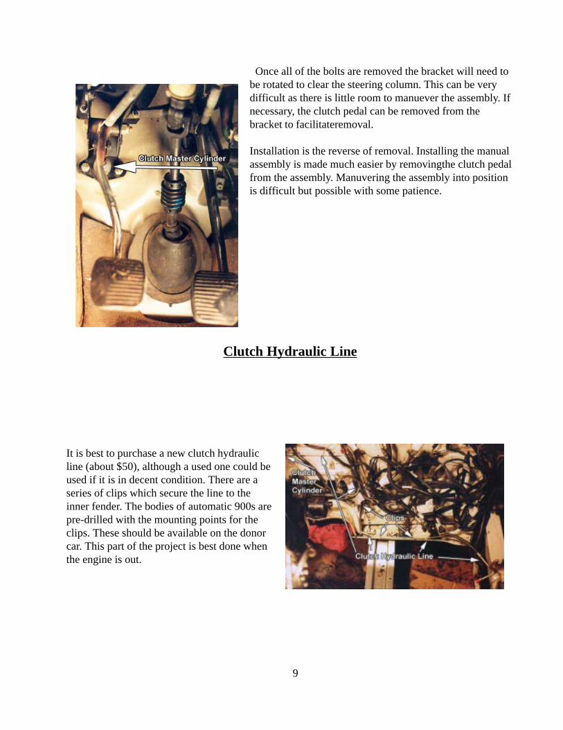
Once all of the bolts are removed the bracket will need tobe rotated to clear the steering column. This can be verydifficult as there is little room to manuever the assembly. Ifnecessary, the clutch pedal can be removed from thebracket to facilitateremoval.
Installation is the reverse of removal. Installing the manualassembly is made much easier by removingthe clutch pedalfrom the assembly. Manuvering the assembly into positionis difficult but possible with some patience.
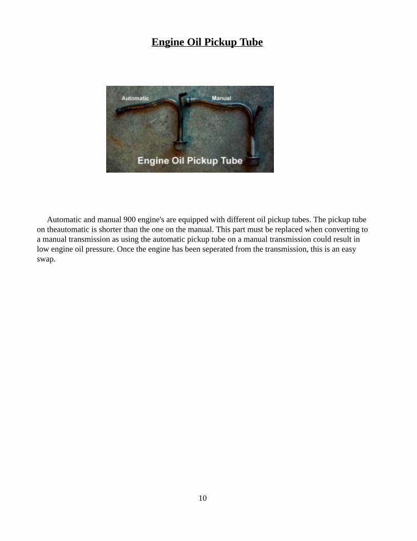
Clutch Hydraulic Line
It is best to purchase a new clutch hydraulicline (about $50), although a used one could beused if it is in decent condition. There are aseries of clips which secure the line to theinner fender. The bodies of automatic 900s arepre-drilled with the mounting points for theclips. These should be available on the donorcar. This part of the project is best done whenthe engine is out.
9
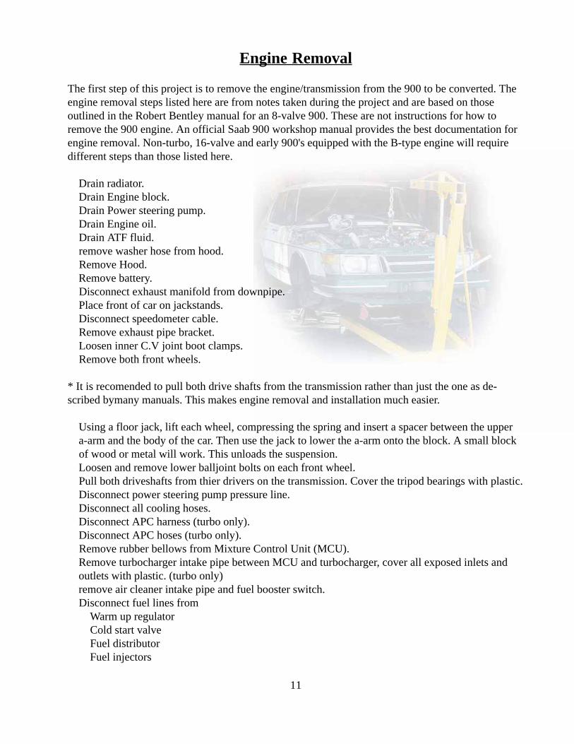
Automatic and manual 900 engine's are equipped with different oil pickup tubes. The pickup tubeon theautomatic is shorter than the one on the manual. This part must be replaced when converting toa manual transmission as using the automatic pickup tube on a manual transmission could result inlow engine oil pressure. Once the engine has been seperated from the transmission, this is an easyswap.
Engine Oil Pickup Tube
10
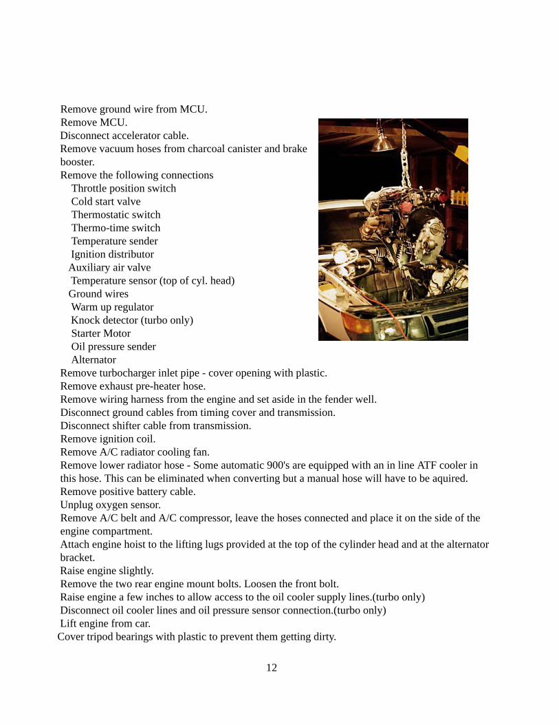
Engine Removal
The first step of this project is to remove the engine/transmission from the 900 to be converted. Theengine removal steps listed here are from notes taken during the project and are based on thoseoutlined in the Robert Bentley manual for an 8-valve 900. These are not instructions for how toremove the 900 engine. An official Saab 900 workshop manual provides the best documentation forengine removal. Non-turbo, 16-valve and early 900's equipped with the B-type engine will requiredifferent steps than those listed here.
Drain radiator. Drain Engine block. Drain Power steering pump. Drain Engine oil. Drain ATF fluid. remove washer hose from hood. Remove Hood. Remove battery. Disconnect exhaust manifold from downpipe. Place front of car on jackstands. Disconnect speedometer cable. Remove exhaust pipe bracket. Loosen inner C.V joint boot clamps. Remove both front wheels.
* It is recomended to pull both drive shafts from the transmission rather than just the one as de-scribed bymany manuals. This makes engine removal and installation much easier.
Using a floor jack, lift each wheel, compressing the spring and insert a spacer between the upper a-arm and the body of the car. Then use the jack to lower the a-arm onto the block. A small block of wood or metal will work. This unloads the suspension. Loosen and remove lower balljoint bolts on each front wheel. Pull both driveshafts from thier drivers on the transmission. Cover the tripod bearings with plastic. Disconnect power steering pump pressure line. Disconnect all cooling hoses. Disconnect APC harness (turbo only). Disconnect APC hoses (turbo only). Remove rubber bellows from Mixture Control Unit (MCU). Remove turbocharger intake pipe between MCU and turbocharger, cover all exposed inlets and outlets with plastic. (turbo only) remove air cleaner intake pipe and fuel booster switch. Disconnect fuel lines from Warm up regulator Cold start valve Fuel distributor Fuel injectors
11
Remove ground wire from MCU. Remove MCU. Disconnect accelerator cable. Remove vacuum hoses from charcoal canister and brake booster. Remove the following connections Throttle position switch Cold start valve Thermostatic switch Thermo-time switch Temperature sender Ignition distributor Auxiliary air valve Temperature sensor (top of cyl. head) Ground wires Warm up regulator Knock detector (turbo only) Starter Motor Oil pressure sender Alternator Remove turbocharger inlet pipe - cover opening with plastic. Remove exhaust pre-heater hose. Remove wiring harness from the engine and set aside in the fender well. Disconnect ground cables from timing cover and transmission. Disconnect shifter cable from transmission. Remove ignition coil. Remove A/C radiator cooling fan. Remove lower radiator hose - Some automatic 900's are equipped with an in line ATF cooler in this hose. This can be eliminated when converting but a manual hose will have to be aquired. Remove positive battery cable. Unplug oxygen sensor. Remove A/C belt and A/C compressor, leave the hoses connected and place it on the side of the engine compartment. Attach engine hoist to the lifting lugs provided at the top of the cylinder head and at the alternator bracket. Raise engine slightly. Remove the two rear engine mount bolts. Loosen the front bolt. Raise engine a few inches to allow access to the oil cooler supply lines.(turbo only) Disconnect oil cooler lines and oil pressure sensor connection.(turbo only) Lift engine from car. Cover tripod bearings with plastic to prevent them getting dirty.
12
Transmission Swap
All major engine components should be cleaned and degreased.
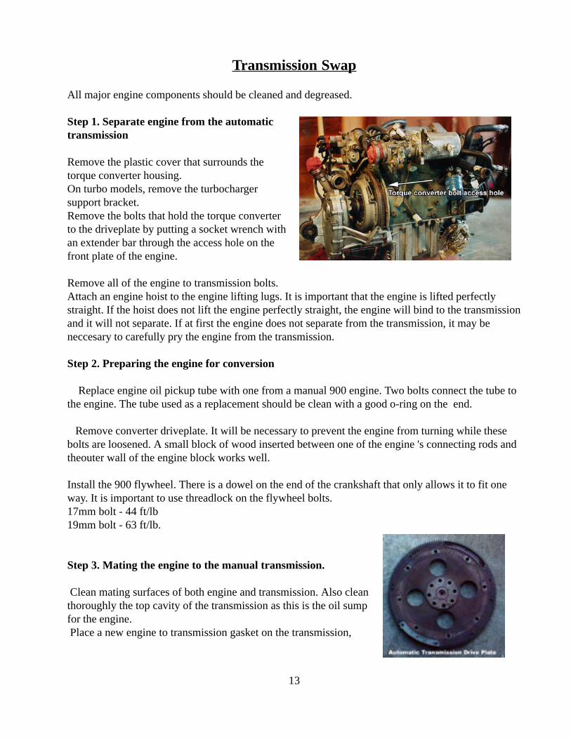
Step 1. Separate engine from the automatictransmission
Remove the plastic cover that surrounds thetorque converter housing.On turbo models, remove the turbochargersupport bracket.Remove the bolts that hold the torque converterto the driveplate by putting a socket wrench withan extender bar through the access hole on thefront plate of the engine.
Remove all of the engine to transmission bolts.Attach an engine hoist to the engine lifting lugs. It is important that the engine is lifted perfectlystraight. If the hoist does not lift the engine perfectly straight, the engine will bind to the transmissionand it will not separate. If at first the engine does not separate from the transmission, it may beneccesary to carefully pry the engine from the transmission.
Step 2. Preparing the engine for conversion
Replace engine oil pickup tube with one from a manual 900 engine. Two bolts connect the tube tothe engine. The tube used as a replacement should be clean with a good o-ring on the end.
Remove converter driveplate. It will be necessary to prevent the engine from turning while thesebolts are loosened. A small block of wood inserted between one of the engine 's connecting rods andtheouter wall of the engine block works well.
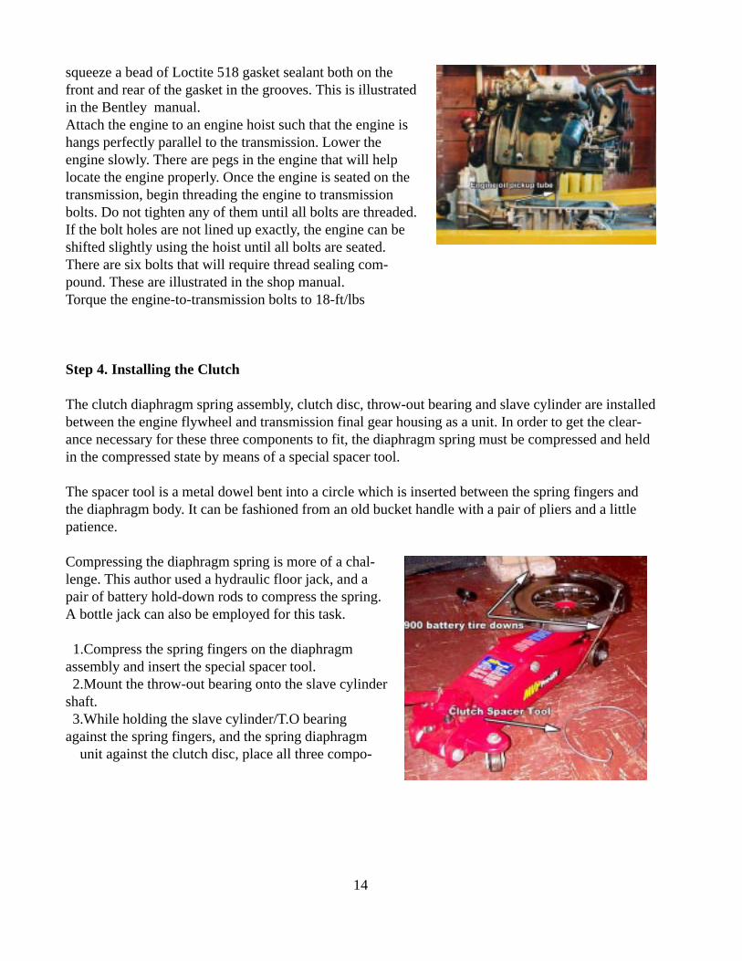
Install the 900 flywheel. There is a dowel on the end of the crankshaft that only allows it to fit oneway. It is important to use threadlock on the flywheel bolts.17mm bolt - 44 ft/lb19mm bolt - 63 ft/lb.
Step 3. Mating the engine to the manual transmission.
Clean mating surfaces of both engine and transmission. Also cleanthoroughly the top cavity of the transmission as this is the oil sumpfor the engine. Place a new engine to transmission gasket on the transmission,
13
squeeze a bead of Loctite 518 gasket sealant both on thefront and rear of the gasket in the grooves. This is illustratedin the Bentley manual.Attach the engine to an engine hoist such that the engine ishangs perfectly parallel to the transmission. Lower theengine slowly. There are pegs in the engine that will helplocate the engine properly. Once the engine is seated on thetransmission, begin threading the engine to transmissionbolts. Do not tighten any of them until all bolts are threaded.If the bolt holes are not lined up exactly, the engine can beshifted slightly using the hoist until all bolts are seated.There are six bolts that will require thread sealing com-pound. These are illustrated in the shop manual.Torque the engine-to-transmission bolts to 18-ft/lbs
Step 4. Installing the Clutch
The clutch diaphragm spring assembly, clutch disc, throw-out bearing and slave cylinder are installedbetween the engine flywheel and transmission final gear housing as a unit. In order to get the clear-ance necessary for these three components to fit, the diaphragm spring must be compressed and heldin the compressed state by means of a special spacer tool.
The spacer tool is a metal dowel bent into a circle which is inserted between the spring fingers andthe diaphragm body. It can be fashioned from an old bucket handle with a pair of pliers and a littlepatience.
Compressing the diaphragm spring is more of a chal-lenge. This author used a hydraulic floor jack, and apair of battery hold-down rods to compress the spring.A bottle jack can also be employed for this task.
1.Compress the spring fingers on the diaphragmassembly and insert the special spacer tool. 2.Mount the throw-out bearing onto the slave cylindershaft. 3.While holding the slave cylinder/T.O bearingagainst the spring fingers, and the spring diaphragm unit against the clutch disc, place all three compo-
14
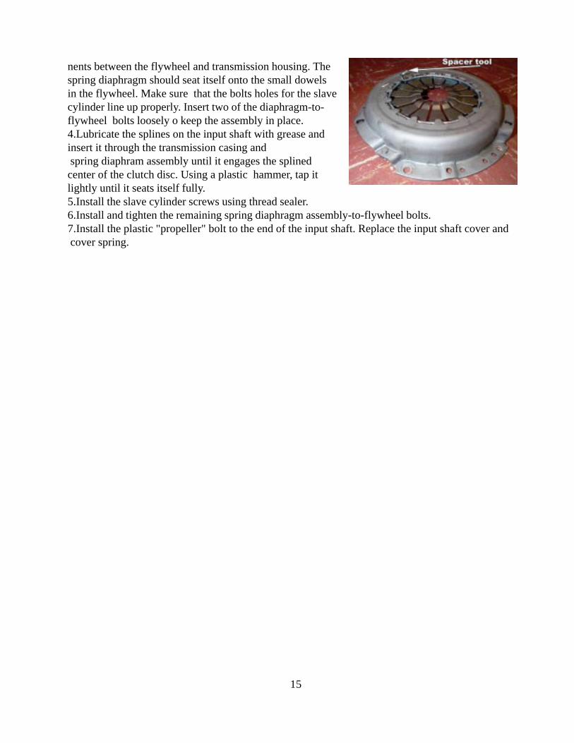
nents between the flywheel and transmission housing. Thespring diaphragm should seat itself onto the small dowelsin the flywheel. Make sure that the bolts holes for the slavecylinder line up properly. Insert two of the diaphragm-to-flywheel bolts loosely o keep the assembly in place.4.Lubricate the splines on the input shaft with grease andinsert it through the transmission casing and spring diaphram assembly until it engages the splinedcenter of the clutch disc. Using a plastic hammer, tap itlightly until it seats itself fully.5.Install the slave cylinder screws using thread sealer.6.Install and tighten the remaining spring diaphragm assembly-to-flywheel bolts.7.Install the plastic "propeller" bolt to the end of the input shaft. Replace the input shaft cover and cover spring.
15