s3c6410-tfa linux developer's guide - · pdf file1.2.25 set and save the real-time clock...
TRANSCRIPT

S3C6410-TFA Linux Developer's Guide


TABLE OF CONTENTS
S3C6410-TFA User Manual ........................................................................ ......................................- 1 -S3C6410-TFALinux development guidelines ........ ............................................. ..............................- 8-- 1.1 the first test of Linux graphical interface Qtopia-2.2.0, Qtopia4 and QtE-4.7.0 System ................ 8-- 1.2 development board through the serial port terminal operations ...................... …......................- 8-- Play mp34.2.1 ......................................... ............... ........................................................................- 9-- 1.2.2 How to stop the program running .......................................... .......................... .....................- 9-- 1.2.3 use the USB / HDD ......................................... .................................................. .....................- 9-- 1.2.4 SD card ............................................ .................................................. ................................. --11-- 1.2.5 How to transfer files to each other with a PC serial port .......... ........................................... .- 12 - 1.2.6 Control panel LED .......................................... ............................................ ...........................- 14- 1.2.7 Test-panel keys .......................................... .................................................. ........................- 15 - 1.2.8 Serial Testing ............................................. ...................................... ....................................- 16 - 1.2.9 beeper ........................................... .................................................. ....................................- 17 - 1.2.10 LCD backlight adjustment control ........................................... ....................... ....................- 18 - 1.2.11 test I2C-EEPROM ........................................... .................................................. ..................- 18 - 1.2.12 AD conversion test ............................................ .................................. ...............................- 19 - 1.2.13 Test TV-OUT ........................................... ............................................................................- 20 - 1.2.14 Test Media Player ............................................ ........................................... .......................- 21 - 1.2.15 use a USB wireless network card or SD WiFi ............................... .................................. ......- 21 - 1.2.16 use telnet on the bbs ........................................... ..................................... ..........................- 29- 1.2.17 How to set the network to access the Internet ..................... ........................................ ......- 30 - 1.2.18 How to set the MAC address ........................................... ................................ ...................- 32-- 1.2.19 How to use Telnet to log on board ......................................... ................................... .........- 34 - 1.2.22 using ftp to transfer files ........................................... ................................. ........................- 35 - 1.2.23 via the web control panel LED ........................................ ........................................ ............- 35 - 1.2.24 How to mount network file systems using NFS ...................... ............................................ .- 36 - 1.2.25 Set and save the real-time clock ......................................... ..................................... ...........- 37 - 1.2.26 How to power down to save data to Flash ............................ .................................. ...........- 37 - 1.2.27 set to run automatically boot program ................................................................. ..............- 38 - 1.2.28 screenshot of how to use commands ................................ ........................................... ......- 39 - 1.2.29 View development board memory information .................. .............................. .................- 39 - 1.3 Installation and set Fedora9 ............................................. ........................ ..............................- 41 - 1.3.1 graphical installation of Fedora 9.0 ........................................... ....................... ....................- 42- 1.3.2 Adding a new user ............................................ ................................. .................................- 55 - 1.3.3 access to Windows system files ......................................... ......................................... .........- 58 - 1.3.4 Configuring Network File System (NFS) services ................... ....................................... .........- 63 - 1.3.5 the establishment of cross-compiler environment ............ ............................. ......................- 66 - 1.4 extracting installer source code and other tools .................. ................................. ...................- 68 - 1.4.1 extract the installation source .......................................... ........................ ...........................- 68 - 1.4.2 Extract to create the target file system ............................ ..................................... ................- 71 1.4.3 Extract installation file system image tool .......................... ......................................... .........- 71 - 1.4.4 extracting installer LogoMaker ........................................... ............................. ....................- 72 - 1.5 Configure and compile U-boot ............................................................... ..................................- 74 -

1.5.1 Configuring the Compile NAND boot support for the U-boot ..... .......................................... .- 74 - 1.5.2 SD card support is compiled configuration to start U-boot .... ........................................... ....- 74 - 1.5.3 U-boot instructions .......................................... ....................................... .............................- 75 - 1.6 Configure and compile the kernel (Kernel) ......................... ............................ .........................- 75 - 1.7 Configure and compile busybox ................................................................. ..............................- 76 - 1.8 Production target file system image .......................................... ....................... ......................- 77 - 1.8.1 Production yaffs2 file system image .......................................... ............................... ............- 77 - 1.8.2 Production ubifs file system image .......................................... ............................. ...............- 78 - 1.8.3 create ext3 file system image .......................................... ..................................... ................- 78 - 1.9 Example . embedded Linux applications ...................................................................................- 78 - 1.9.1 Hello, World! ........................................... .......................................... ..................................- 79 - 1.9.2 LED test program ............................................ ...................................... ...............................- 82 - 1.9.3 Test button ............................................. ......................................... ....................................- 84 - 1.9.4 PWM control buzzer programming examples ............................. ............................. .............- 85 - 1.9.5 I2C-EEPROM programming examples ................................................................... .................- 89 - 1.9.6 Example... Serial Programming .................................................. ...........................................- 92 - 1.9.7 UDP network programming ............................................ ....................... ..............................- 98 - 1.9.8 Example .. math library calls .............................................................................. .................- 103 - 1.9.9 Example. thread programming ................................................................ ...........................- 104 - 1.9.10 Pipeline Application Programming Example - Web Control LED .. .......................................- 106 - 1.9.11 Based on the C + + Hello, World ......................................... ............................... .............. --111-- 1.10 Example .. embedded Linux drivers .............................................................. ……................. - 112 - 1.10.1 Hello, Module-simple embedded Linux driver module .................................. ................... - 112 - 1.10.2 LED driver ............................................ .................................................. ......................... --116-- 1.10.3 Key Drivers ............................................ ................................................. ......................... - 119 - 1.11 .Compile Qtopia-2.2.0 ........................................................................ .................................- 125 - 1.11.1 extracting installer source code ................................................................ ........................- 125 - 1.11.2 Compiling and running the x86 version of Qtopia-2.2.0 ............. ........................................- 125 - 1.11.3 compile and run arm version of Qtopia-2.2.0 .................. .................................................- 126 - 1.12 .Compile QtE-4.7.0 ......................................................................... .....................................- 127 - 1.12.1 extracting installer source code ................................................................. .......................- 127 - Arm version 1.12.2 compile and run the QtE-4.7.0 .................................... .............................. ....- 128 - 1.13 Compile Qtopia4 (Qt-Extended-4.4.3) ..................................................................... .............- 129 - 1.13.1 extracting installer source code ................................................................. .......................- 129 - 1.13.2 Compiling and running the x86 version of Qt-Extended-4.4.3 .............................................- 129 - 1.13.3 compile and run arm version of the Qt-Extended-4.4.3 ........... ..........................................- 130 - 1.14 choose which version of Qt to develop .............. .................................................. ..............- 131 -


S3C6410-TFA Linux Developer's Guide
S3C6410-TFA software and S3C6410-TFA is fully compatible, so the path is set, the default configuration file, have
followed the S3C6410-TFA of manuals, based on the actual situation may be slightly different, if in doubt, please
contact us: info @ esys.ir
1.1 The first test of Linux graphical interface Qtopia-2.2.0, Qtopia4 and QtE-4.7.0 system
Please refer to "S3C6410-TFA functional test guide"
1.2 Development board through the serial port terminal operations
Note: Each learning expectations embedded Linux fans should learn to skillfully use the terminal console
operation, all platforms Linux commands are similar, over 99% of the commands are the same.Prior to the
operation of this section, please follow the "S3C6410-TFA Brush Guide" of the steps correctly set up
HyperTerminal.
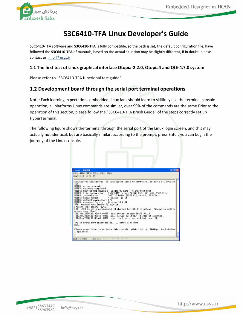
The following figure shows the terminal through the serial port of the Linux login screen, and this may
actually not identical, but are basically similar, according to the prompt, press Enter, you can begin the
journey of the Linux console.
4.2.1 mp3 player
madplay is a portable console based mp3 player.It has a variety of playback control mode, the easiest to
use is:
# Madplay your.mp3
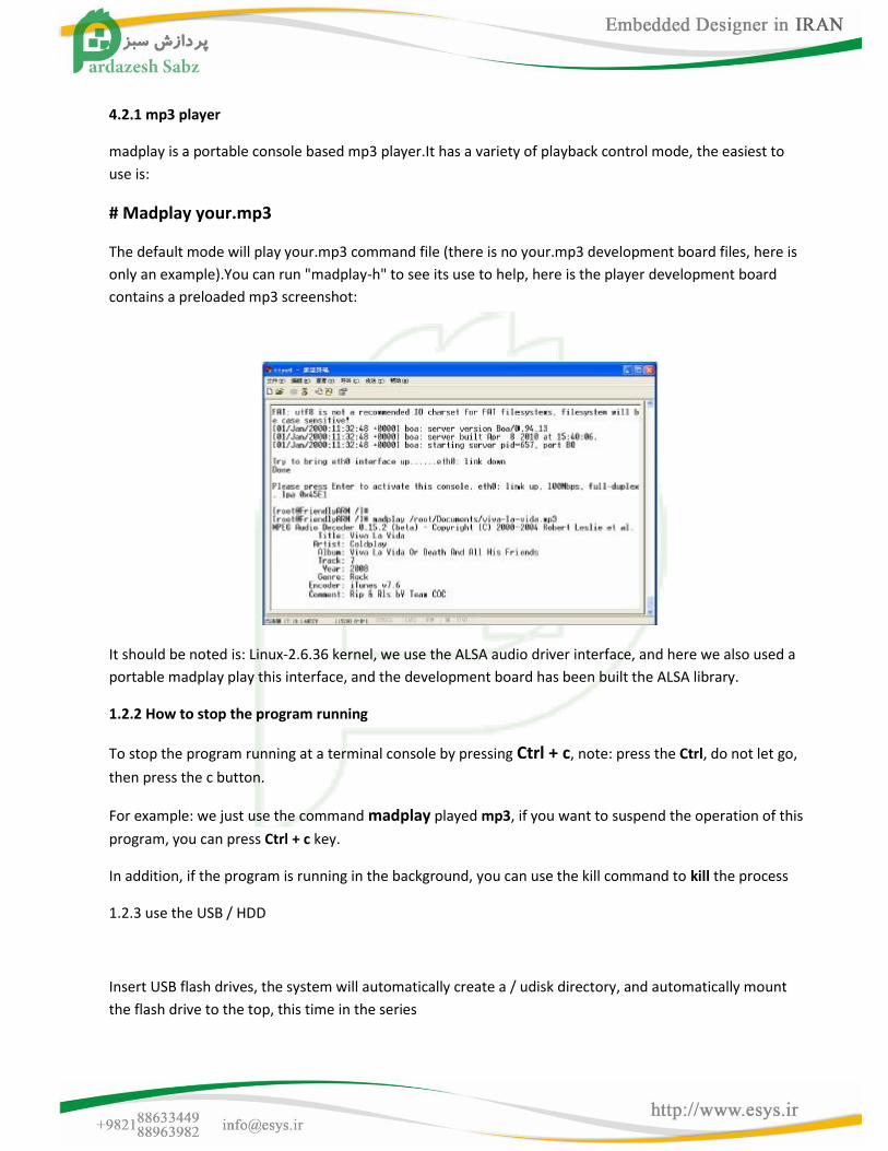
The default mode will play your.mp3 command file (there is no your.mp3 development board files, here is
only an example).You can run "madplay-h" to see its use to help, here is the player development board
contains a preloaded mp3 screenshot:
It should be noted is: Linux-2.6.36 kernel, we use the ALSA audio driver interface, and here we also used a
portable madplay play this interface, and the development board has been built the ALSA library.
1.2.2 How to stop the program running
To stop the program running at a terminal console by pressing Ctrl + c, note: press the Ctrl, do not let go,
then press the c button.
For example: we just use the command madplay played mp3, if you want to suspend the operation of this
program, you can press Ctrl + c key.
In addition, if the program is running in the background, you can use the kill command to kill the process
1.2.3 use the USB / HDD
Insert USB flash drives, the system will automatically create a / udisk directory, and automatically mount
the flash drive to the top, this time in the series
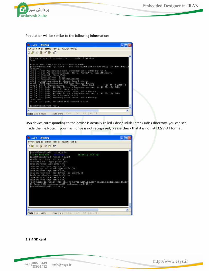
Population will be similar to the following information:
USB device corresponding to the device is actually called / dev / udisk.Enter / udisk directory, you can see
inside the file.Note: If your flash drive is not recognized, please check that it is not FAT32/VFAT format
1.2.4 SD card
Information:
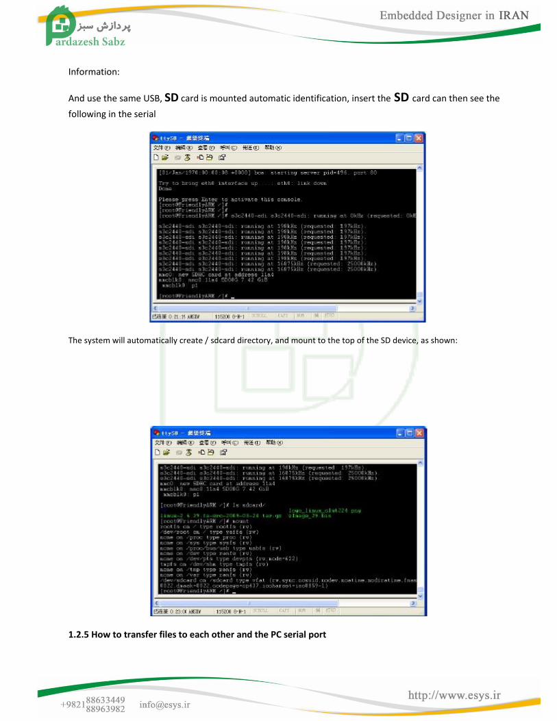
And use the same USB, SD card is mounted automatic identification, insert the SD card can then see the
following in the serial
The system will automatically create / sdcard directory, and mount to the top of the SD device, as shown:
1.2.5 How to transfer files to each other and the PC serial port
Note: Use the USB to serial port, there may not be smooth, and we think it's USB to serial cable quality and
performance related.
When the log through the serial port terminal, you can use the rz or sz command via the serial port and PC
to transfer files to each other, as follows.
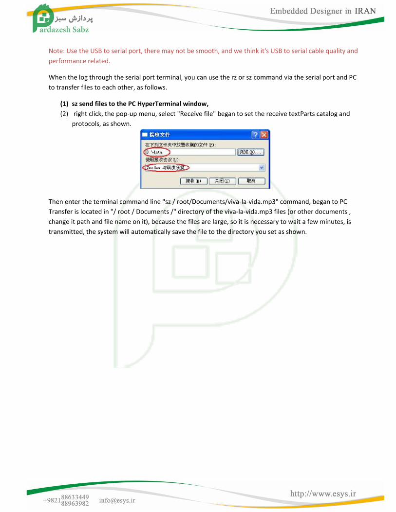
(1) sz send files to the PC HyperTerminal window,
(2) right click, the pop-up menu, select "Receive file" began to set the receive textParts catalog and
protocols, as shown.
Then enter the terminal command line "sz / root/Documents/viva-la-vida.mp3" command, began to PC
Transfer is located in "/ root / Documents /" directory of the viva-la-vida.mp3 files (or other documents ,
change it path and file name on it), because the files are large, so it is necessary to wait a few minutes, is
transmitted, the system will automatically save the file to the directory you set as shown.
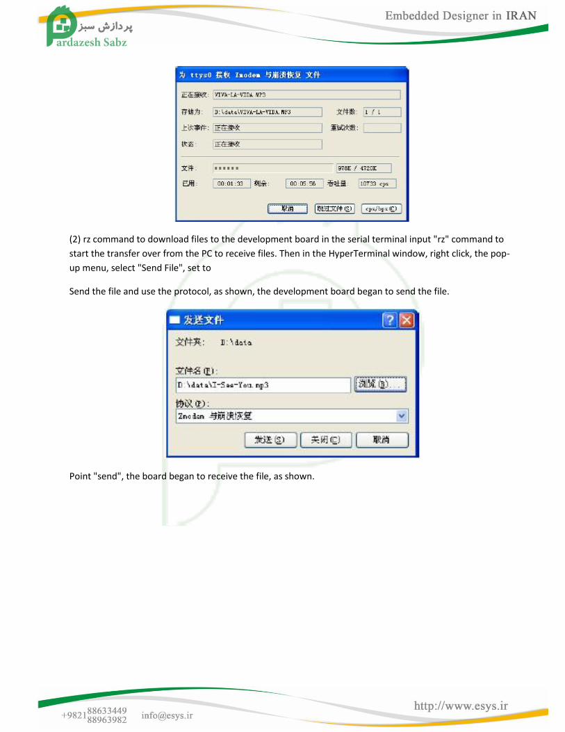
(2) rz command to download files to the development board in the serial terminal input "rz" command to
start the transfer over from the PC to receive files. Then in the HyperTerminal window, right click, the pop-
up menu, select "Send File", set to
Send the file and use the protocol, as shown, the development board began to send the file.
Point "send", the board began to receive the file, as shown.
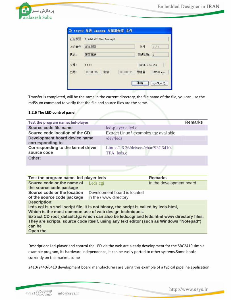
Transfer is completed, will be the same in the current directory, the file name of the file, you can use the
md5sum command to verify that the file and source files are the same.
1.2.6 The LED control panel
Test the program name: led-player Remarks
Source code file name led-player.c led.c Source code location of the CD Extract Linux \ examples.tgz available Development board device name corresponding to
/dev/leds
Corresponding to the kernel driver source code
Linux-2.6.36/drivers/char/S3C6410-
TFA_leds.c
Other:
Test the program name: led-player leds Remarks Source code or the name of the source code package
Leds.cgi In the development board
Source code or the location of the source code package
Development board is located in the / www directory
Description: leds.cgi is a shell script file, it is not binary, the script is called by leds.html, Which is the most common use of web design techniques. Extract CD root_default.tgz which can also be leds.cgi and leds.html www directory files, They are scripts, source code itself, using any text editor (such as Windows "Notepad") can be Open the.
Description: Led-player and control the LED via the web are a early development for the SBC2410 simple
example program, its hardware independence, it can be easily ported to other systems.Some books
currently on the market, some
2410/2440/6410 development board manufacturers are using this example of a typical pipeline application.
(1) LED server
Boot into the system, will automatically run an LED service program (/ etc / rc.d / init.d / leds), it is a led-player calls a
script, led-player is running, will be in the / tmp directory, create a led-control the file, and send different parameters
to the pipeline led flashing mode can be changed:
# Echo 0 0.2> / tmp / led-control
After running this command, four users will be led each time interval of 0.2 seconds to run Marquee.
# Echo 1 0.2> / tmp / led-control
Run the command, led four users will be the time interval of 0.2 seconds to run accumulator.
# / Etc / rc.d / init.d / leds stop
After running this command, four user-led will stop flashing.
# / Etc / rc.d / init.d / leds start
Run the command, led four users will start flashing.
(2) individually controlled LED
/ Bin / leds can be controlled is a single led the utility to use the leds must stop led-player, the following
command:
# / Etc / rc.d / init.d / leds stop
This command will stop led led-player of the manipulation.led to use as follows:
[Root @ fa /] # led
Usage: leds led_no 0 | 1led_no to operate the led (for 0,1,2,3), 0 and 1 represent off and light up.
# Led 2 1
LED3 will light
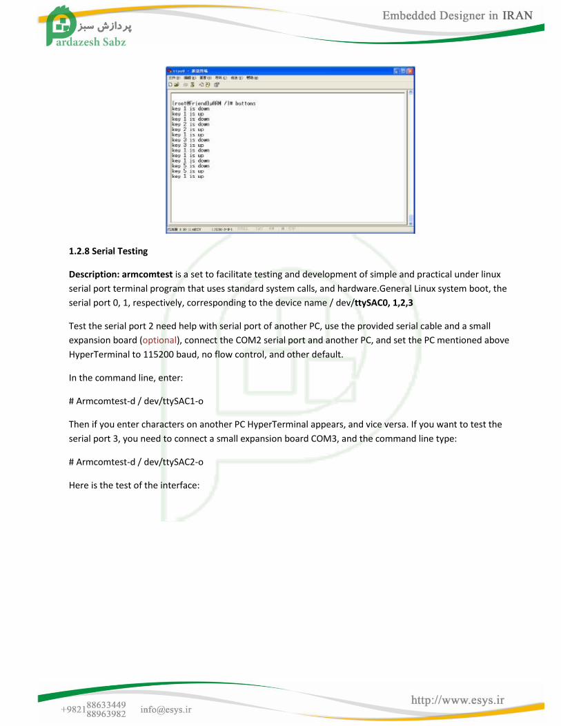
1.2.7 Buttons on the test
Test the program name: buttons Remarks Test program source code file name Buttons_test.c Location of the test program source code Extract linux \ examples.tgz available Development board device name corresponding to /dev/buttons Corresponding to the kernel driver source code
Linux-2.6.36/drivers/char/S3C6410-
TFA_buttons.c
Other:
In the command line input "buttons" command, then press the key development board, you can display the
corresponding key, as shown in Figure
1.2.8 Serial Testing
Description: armcomtest is a set to facilitate testing and development of simple and practical under linux
serial port terminal program that uses standard system calls, and hardware.General Linux system boot, the
serial port 0, 1, respectively, corresponding to the device name / dev/ttySAC0, 1,2,3
Test the serial port 2 need help with serial port of another PC, use the provided serial cable and a small
expansion board (optional), connect the COM2 serial port and another PC, and set the PC mentioned above
HyperTerminal to 115200 baud, no flow control, and other default.
In the command line, enter:
# Armcomtest-d / dev/ttySAC1-o
Then if you enter characters on another PC HyperTerminal appears, and vice versa. If you want to test the
serial port 3, you need to connect a small expansion board COM3, and the command line type:
# Armcomtest-d / dev/ttySAC2-o
Here is the test of the interface:
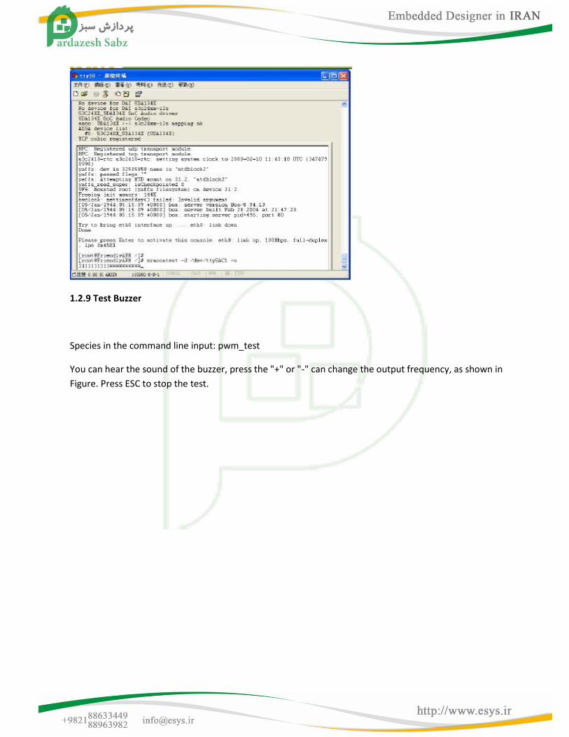
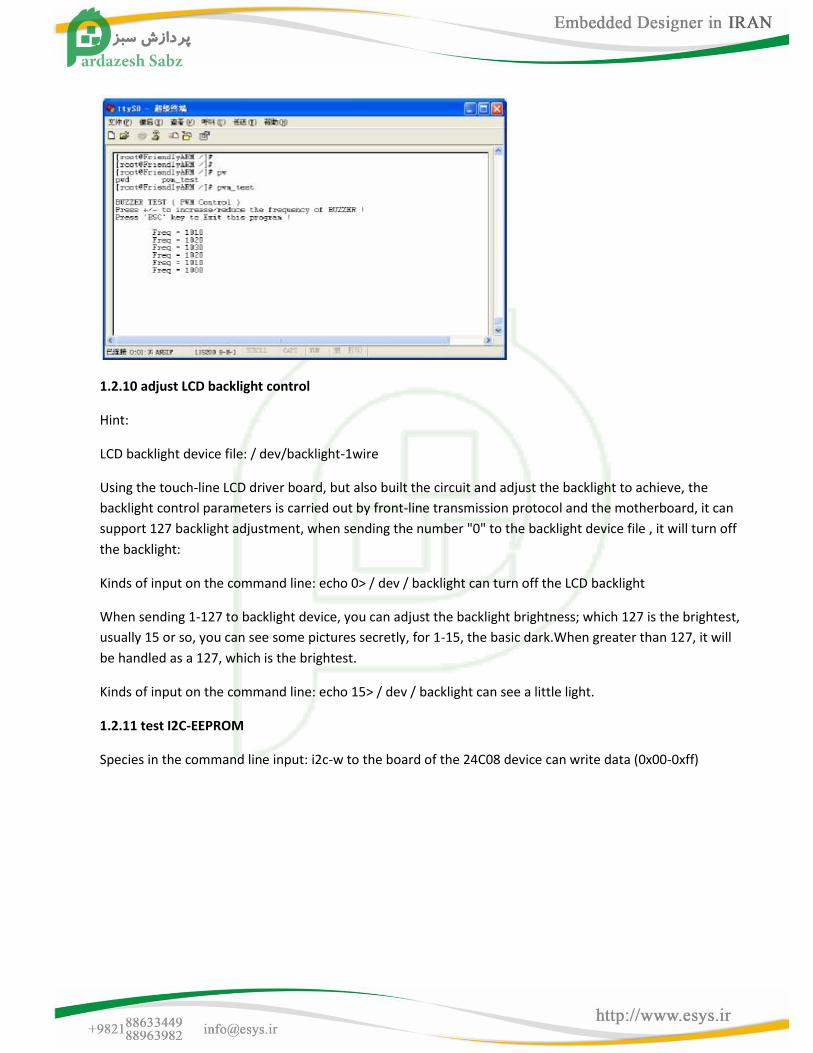
1.2.9 Test Buzzer
Species in the command line input: pwm_test
You can hear the sound of the buzzer, press the "+" or "-" can change the output frequency, as shown in
Figure. Press ESC to stop the test.
1.2.10 adjust LCD backlight control
Hint:
LCD backlight device file: / dev/backlight-1wire
Using the touch-line LCD driver board, but also built the circuit and adjust the backlight to achieve, the
backlight control parameters is carried out by front-line transmission protocol and the motherboard, it can
support 127 backlight adjustment, when sending the number "0" to the backlight device file , it will turn off
the backlight:
Kinds of input on the command line: echo 0> / dev / backlight can turn off the LCD backlight
When sending 1-127 to backlight device, you can adjust the backlight brightness; which 127 is the brightest,
usually 15 or so, you can see some pictures secretly, for 1-15, the basic dark.When greater than 127, it will
be handled as a 127, which is the brightest.
Kinds of input on the command line: echo 15> / dev / backlight can see a little light.
1.2.11 test I2C-EEPROM
Species in the command line input: i2c-w to the board of the 24C08 device can write data (0x00-0xff)
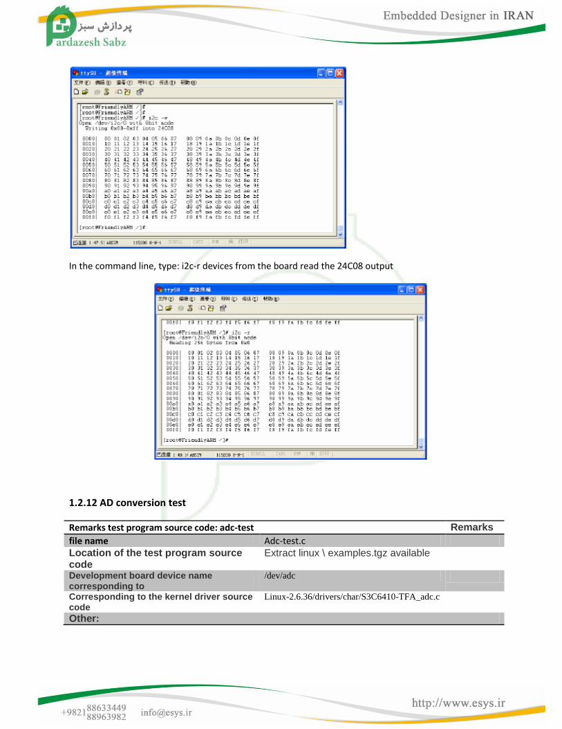
In the command line, type: i2c-r devices from the board read the 24C08 output
1.2.12 AD conversion test
Remarks test program source code: adc-test Remarks
file name Adc-test.c Location of the test program source code
Extract linux \ examples.tgz available
Development board device name corresponding to
/dev/adc
Corresponding to the kernel driver source code
Linux-2.6.36/drivers/char/S3C6410-TFA_adc.c
Other:
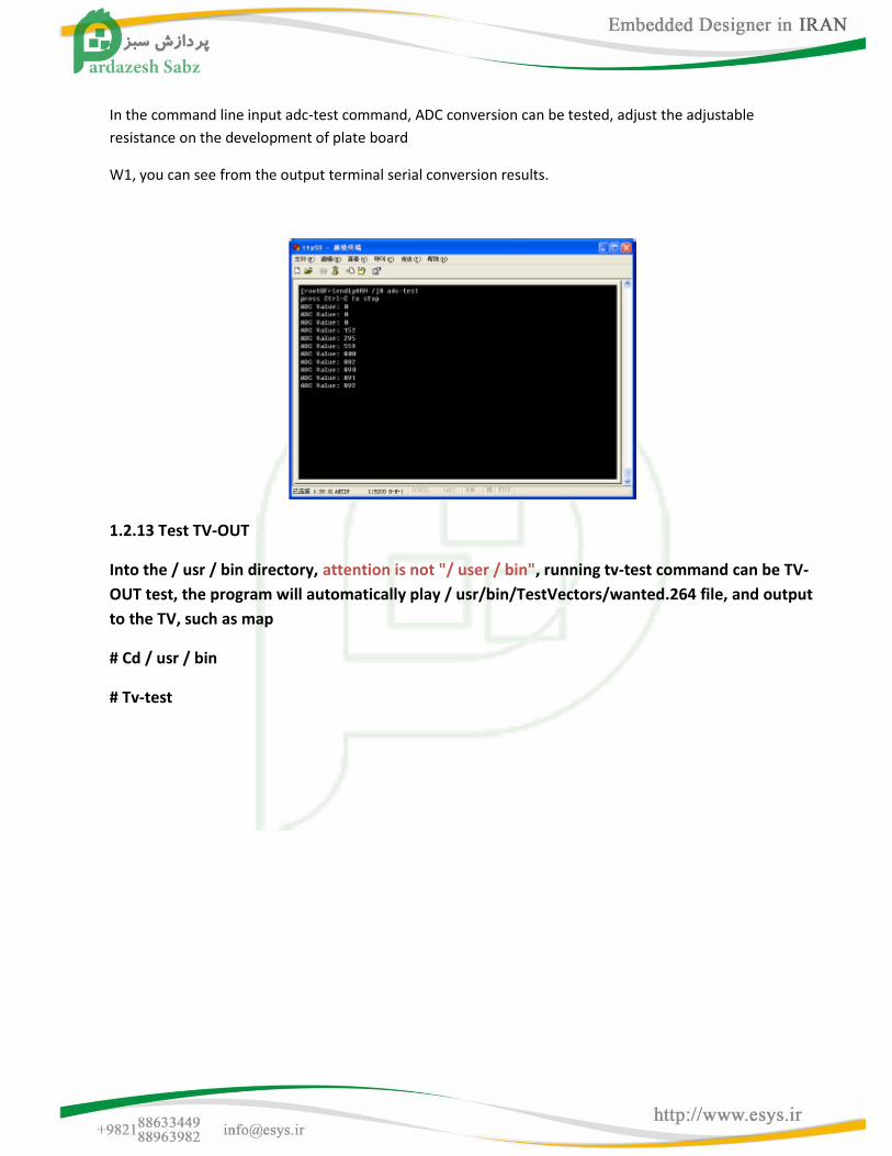
In the command line input adc-test command, ADC conversion can be tested, adjust the adjustable
resistance on the development of plate board
W1, you can see from the output terminal serial conversion results.
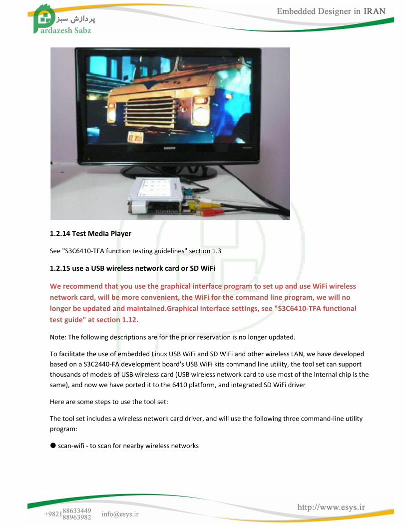
1.2.13 Test TV-OUT
Into the / usr / bin directory, attention is not "/ user / bin", running tv-test command can be TV-
OUT test, the program will automatically play / usr/bin/TestVectors/wanted.264 file, and output
to the TV, such as map
# Cd / usr / bin
# Tv-test
1.2.14 Test Media Player
See "S3C6410-TFA function testing guidelines" section 1.3
1.2.15 use a USB wireless network card or SD WiFi
We recommend that you use the graphical interface program to set up and use WiFi wireless
network card, will be more convenient, the WiFi for the command line program, we will no
longer be updated and maintained.Graphical interface settings, see "S3C6410-TFA functional
test guide" at section 1.12.
Note: The following descriptions are for the prior reservation is no longer updated.
To facilitate the use of embedded Linux USB WiFi and SD WiFi and other wireless LAN, we have developed
based on a S3C2440-FA development board's USB WiFi kits command line utility, the tool set can support
thousands of models of USB wireless card (USB wireless network card to use most of the internal chip is the
same), and now we have ported it to the 6410 platform, and integrated SD WiFi driver
Here are some steps to use the tool set:
The tool set includes a wireless network card driver, and will use the following three command-line utility
program:
scan-wifi - to scan for nearby wireless networks
start-wifi - connect to open wireless network
stop-wifi - stop using the wireless network is installed in the three program development board / usr /
sbin directory
1. Scan for nearby wireless networks
Note: The following example is using a USB wireless adapter Model: TL-WN321G +, SD-WiFi module and
use similar, it is no longer alone shows.
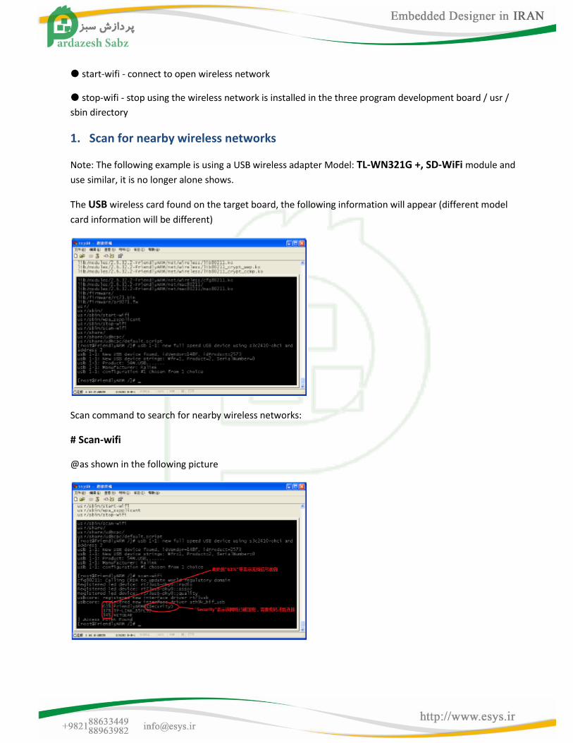
The USB wireless card found on the target board, the following information will appear (different model
card information will be different)
Scan command to search for nearby wireless networks:
# Scan-wifi
@as shown in the following picture
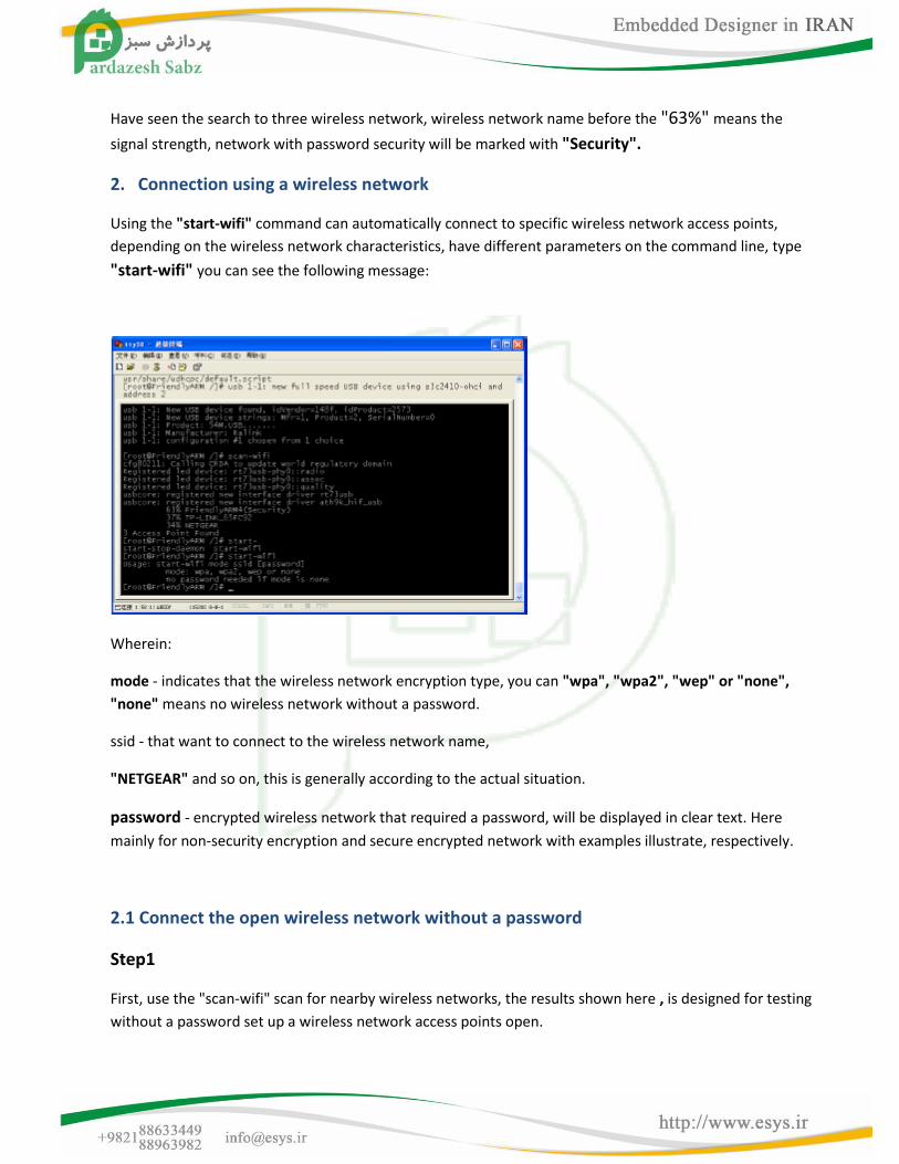
Have seen the search to three wireless network, wireless network name before the "63%" means the
signal strength, network with password security will be marked with "Security".
2. Connection using a wireless network
Using the "start-wifi" command can automatically connect to specific wireless network access points,
depending on the wireless network characteristics, have different parameters on the command line, type
"start-wifi" you can see the following message:
Wherein:
mode - indicates that the wireless network encryption type, you can "wpa", "wpa2", "wep" or "none",
"none" means no wireless network without a password.
ssid - that want to connect to the wireless network name,
"NETGEAR" and so on, this is generally according to the actual situation.
password - encrypted wireless network that required a password, will be displayed in clear text. Here
mainly for non-security encryption and secure encrypted network with examples illustrate, respectively.
2.1 Connect the open wireless network without a password
Step1
First, use the "scan-wifi" scan for nearby wireless networks, the results shown here , is designed for testing
without a password set up a wireless network access points open.
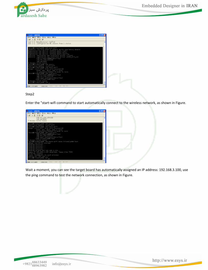
Step2
Enter the "start-wifi command to start automatically connect to the wireless network, as shown in Figure.
Wait a moment, you can see the target board has automatically assigned an IP address: 192.168.3.100, use
the ping command to test the network connection, as shown in Figure.

At this point you can enter on the PC browser development board ip address: 192.168.3.100, see the
development board in web server, as shown in Figure.
2.2 connection requires a password to use secure wireless network
connection wireless network with a password similar to the steps and over, but need to know in advance
when connecting Wireless
Network encryption type and password, encryption type if you do not know, only in "wpa", "wpa2",
"wep" guess of these three options, and specific steps are as follows:
Step1
Set the security mode wireless router, wireless router model used here is: TL-WR740N, open the Settings
page, shown in Figure
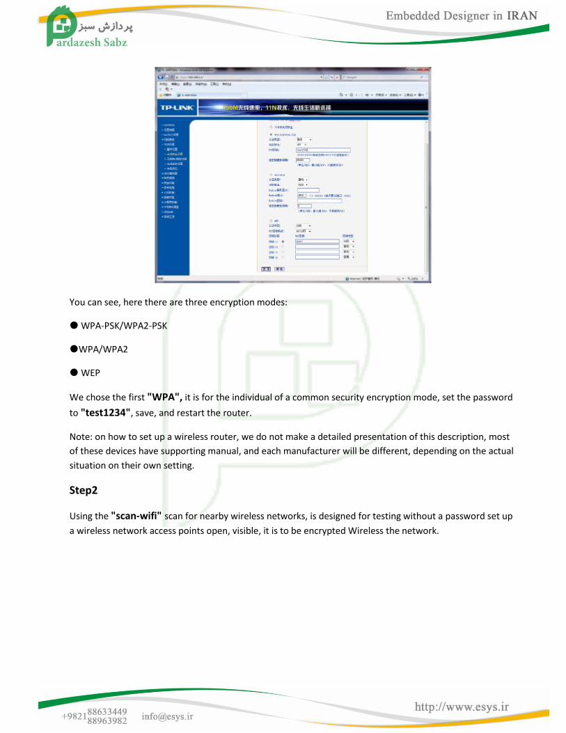
You can see, here there are three encryption modes:
WPA-PSK/WPA2-PSK
WPA/WPA2
WEP
We chose the first "WPA", it is for the individual of a common security encryption mode, set the password
to "test1234", save, and restart the router.
Note: on how to set up a wireless router, we do not make a detailed presentation of this description, most
of these devices have supporting manual, and each manufacturer will be different, depending on the actual
situation on their own setting.
Step2
Using the "scan-wifi" scan for nearby wireless networks, is designed for testing without a password set up
a wireless network access points open, visible, it is to be encrypted Wireless the network.
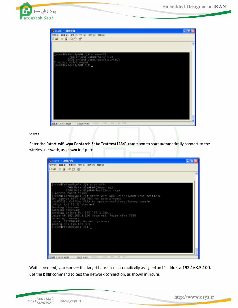
Step3
Enter the "start-wifi wpa Pardazeh Sabz-Test test1234" command to start automatically connect to the
wireless network, as shown in Figure.
Wait a moment, you can see the target board has automatically assigned an IP address: 192.168.3.100,
use the ping command to test the network connection, as shown in Figure.
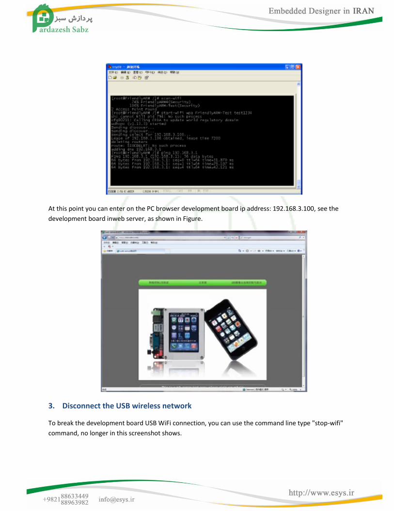
At this point you can enter on the PC browser development board ip address: 192.168.3.100, see the
development board inweb server, as shown in Figure.
3. Disconnect the USB wireless network
To break the development board USB WiFi connection, you can use the command line type "stop-wifi"
command, no longer in this screenshot shows.
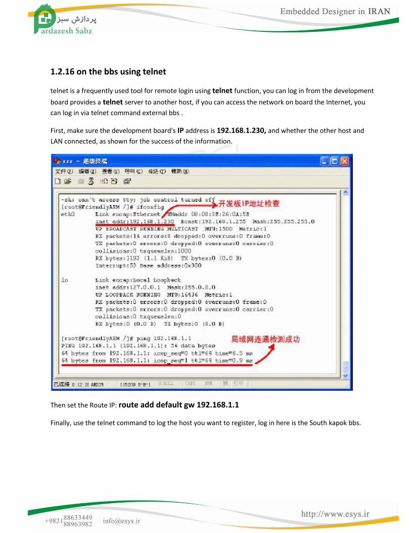
1.2.16 on the bbs using telnet
telnet is a frequently used tool for remote login using telnet function, you can log in from the development
board provides a telnet server to another host, if you can access the network on board the Internet, you
can log in via telnet command external bbs .
First, make sure the development board's IP address is 192.168.1.230, and whether the other host and
LAN connected, as shown for the success of the information.
Then set the Route IP: route add default gw 192.168.1.1
Finally, use the telnet command to log the host you want to register, log in here is the South kapok bbs.
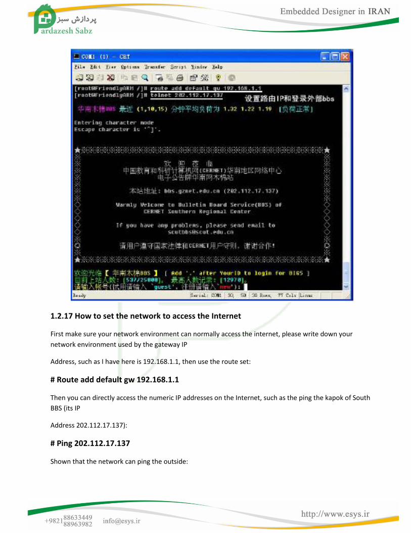
1.2.17 How to set the network to access the Internet
First make sure your network environment can normally access the internet, please write down your
network environment used by the gateway IP
Address, such as I have here is 192.168.1.1, then use the route set:
# Route add default gw 192.168.1.1
Then you can directly access the numeric IP addresses on the Internet, such as the ping the kapok of South
BBS (its IP
Address 202.112.17.137):
# Ping 202.112.17.137
Shown that the network can ping the outside:
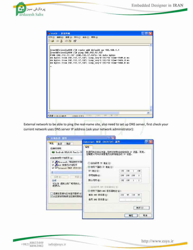
External network to be able to ping the real-name site, also need to set up DNS server, first check your
current network uses DNS server IP address (ask your network administrator):
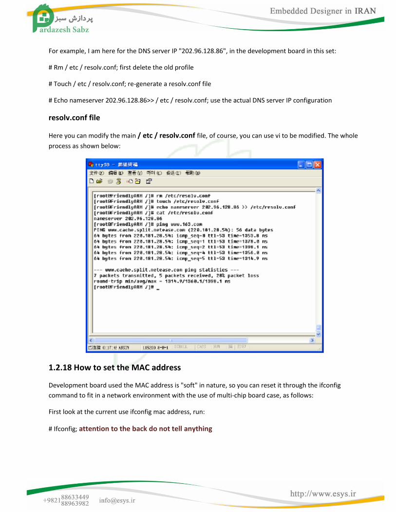
For example, I am here for the DNS server IP "202.96.128.86", in the development board in this set:
# Rm / etc / resolv.conf; first delete the old profile
# Touch / etc / resolv.conf; re-generate a resolv.conf file
# Echo nameserver 202.96.128.86>> / etc / resolv.conf; use the actual DNS server IP configuration
resolv.conf file
Here you can modify the main / etc / resolv.conf file, of course, you can use vi to be modified. The whole
process as shown below:
1.2.18 How to set the MAC address
Development board used the MAC address is "soft" in nature, so you can reset it through the ifconfig
command to fit in a network environment with the use of multi-chip board case, as follows:
First look at the current use ifconfig mac address, run:
# Ifconfig; attention to the back do not tell anything
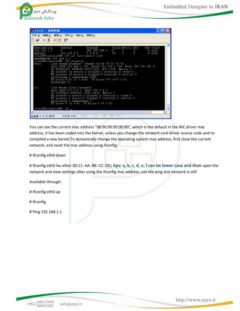
You can see the current mac address "08:90:90:90:90:90", which is the default in the NIC driver mac
address, it has been coded into the kernel, unless you change the network card driver source code and re-
compiled a new kernel.To dynamically change the operating system mac address, first close the current
network, and reset the mac address using ifconfig:
# Ifconfig eth0 down
# Ifconfig eth0 hw ether 00:11: AA: BB: CC: DD; tips: a, b, c, d, e, f can be lower case and then open the
network and view settings after using the ifconfig mac address, use the ping test network is still
Available through:
# Ifconfig eth0 up
# Ifconfig
# Ping 192.168.1.1
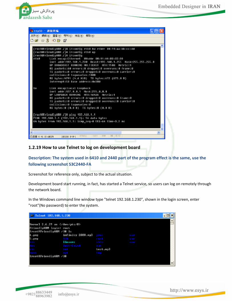
1.2.19 How to use Telnet to log on development board
Description: The system used in 6410 and 2440 part of the program effect is the same, use the
following screenshot S3C2440-FA
Screenshot for reference only, subject to the actual situation.
Development board start running, in fact, has started a Telnet service, so users can log on remotely through
the network board.
In the Windows command line window type "telnet 192.168.1.230", shown in the login screen, enter
"root"(No password) to enter the system.
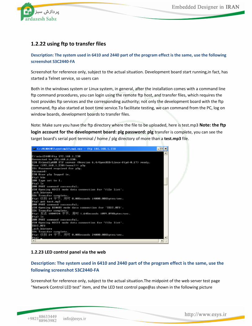
1.2.22 using ftp to transfer files
Description: The system used in 6410 and 2440 part of the program effect is the same, use the following
screenshot S3C2440-FA
Screenshot for reference only, subject to the actual situation. Development board start running,in fact, has
started a Telnet service, so users can
Both in the windows system or Linux system, in general, after the installation comes with a command line
ftp command procedures, you can login using the remote ftp host, and transfer files, which requires the
host provides ftp services and the corresponding authority; not only the development board with the ftp
command, ftp also started at boot time service.To facilitate testing, we can command from the PC, log on
window boards, development boards to transfer files.
Note: Make sure you have the ftp directory where the file to be uploaded, here is test.mp3 Note: the ftp
login account for the development board: plg password: plg transfer is complete, you can see the
target board's serial port terminal / home / plg directory of more than a test.mp3 file.
1.2.23 LED control panel via the web
Description: The system used in 6410 and 2440 part of the program effect is the same, use the
following screenshot S3C2440-FA
Screenshot for reference only, subject to the actual situation.The midpoint of the web server test page
"Network Control LED test" item, and the LED test control page@as shown in the following picture
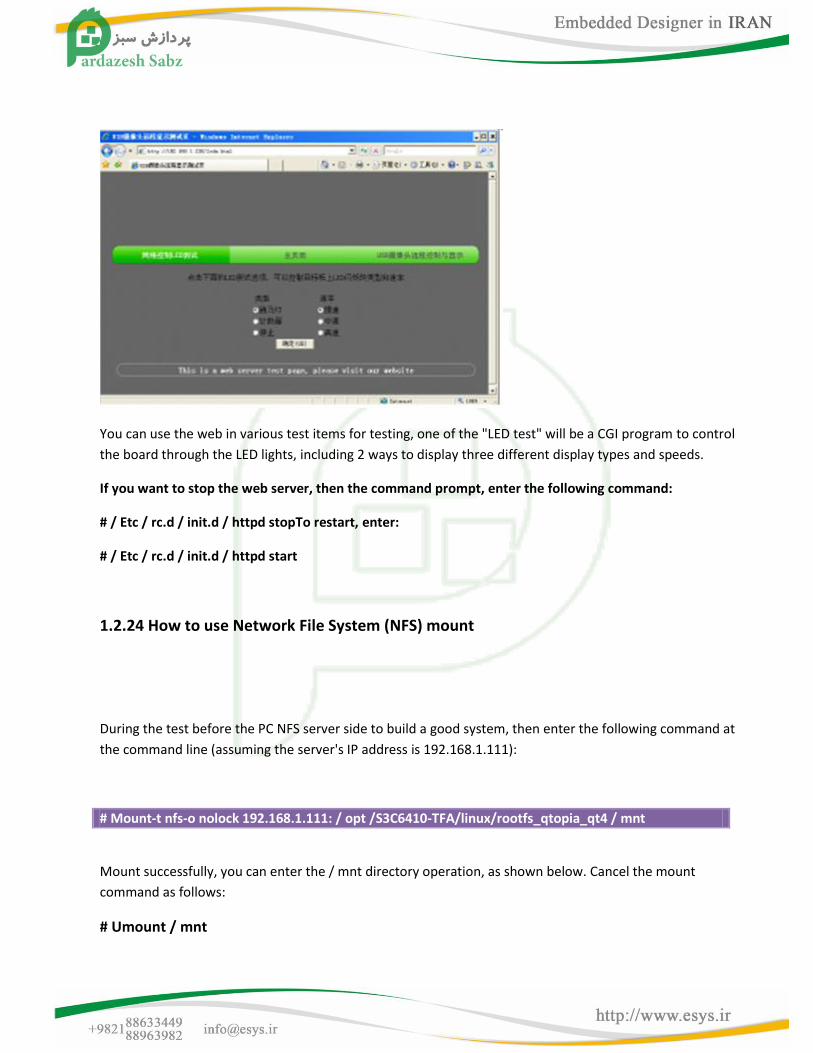
You can use the web in various test items for testing, one of the "LED test" will be a CGI program to control
the board through the LED lights, including 2 ways to display three different display types and speeds.
If you want to stop the web server, then the command prompt, enter the following command:
# / Etc / rc.d / init.d / httpd stopTo restart, enter:
# / Etc / rc.d / init.d / httpd start
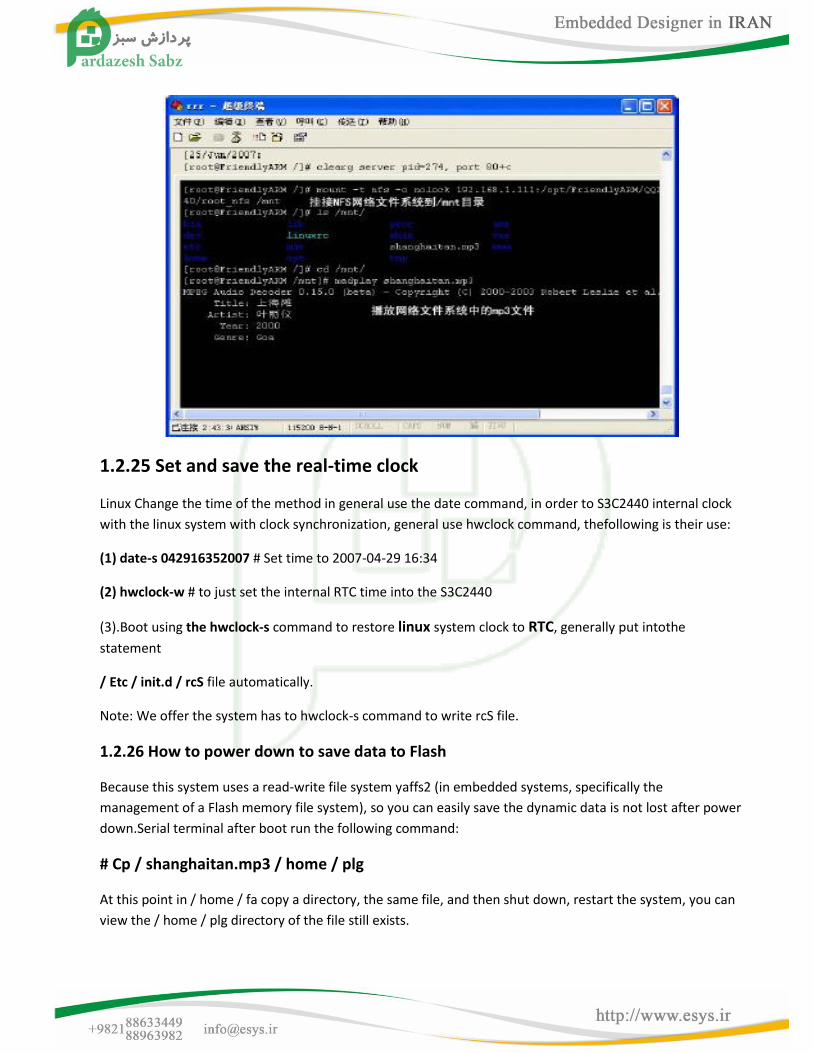
1.2.24 How to use Network File System (NFS) mount
During the test before the PC NFS server side to build a good system, then enter the following command at
the command line (assuming the server's IP address is 192.168.1.111):
# Mount-t nfs-o nolock 192.168.1.111: / opt /S3C6410-TFA/linux/rootfs_qtopia_qt4 / mnt
Mount successfully, you can enter the / mnt directory operation, as shown below. Cancel the mount
command as follows:
# Umount / mnt
1.2.25 Set and save the real-time clock
Linux Change the time of the method in general use the date command, in order to S3C2440 internal clock
with the linux system with clock synchronization, general use hwclock command, thefollowing is their use:
(1) date-s 042916352007 # Set time to 2007-04-29 16:34
(2) hwclock-w # to just set the internal RTC time into the S3C2440
(3).Boot using the hwclock-s command to restore linux system clock to RTC, generally put intothe
statement
/ Etc / init.d / rcS file automatically.
Note: We offer the system has to hwclock-s command to write rcS file.
1.2.26 How to power down to save data to Flash
Because this system uses a read-write file system yaffs2 (in embedded systems, specifically the
management of a Flash memory file system), so you can easily save the dynamic data is not lost after power
down.Serial terminal after boot run the following command:
# Cp / shanghaitan.mp3 / home / plg
At this point in / home / fa copy a directory, the same file, and then shut down, restart the system, you can
view the / home / plg directory of the file still exists.

1.2.27 Set the program to run automatically boot
With the startup script can set a variety of programs to run automatically after boot, you can also set other
system settings, which is somewhat similar to the Windows system Autobat automatic batch file to start
the script in the board's / etc / init.d / rcS, content as follows (the actual content may not fully consistent
with this):
#! / Bin / sh
PATH = / sbin: / bin: / usr / sbin: / usr / bin: / usr / local / bin: runlevel = S prevlevel = N umask 022 export PATH runlevel prevlevel # # Trap CTRL-C & c only in this shell so we can interrupt subprocesses. # trap ":" INT QUIT TSTP / Bin / hostname [-E / proc / 1] | | / bin / mount-n-t proc none / proc [-E / sys / class] | | / bin / mount-n-t sysfs none / sys [-E / dev / tty] | | / bin / mount-t ramfs none / dev / Bin / mount-n-t usbfs none / proc / bus / usb echo / sbin / mdev> / proc / sys / kernel / hotplug / Sbin / mdev-s / Bin / hotplug # Mounting file system specified in / etc / fstab mkdir-p / dev / pts mkdir-p / dev / shm / Bin / mount-n-t devpts none / dev / pts-o mode = 0622 / Bin / mount-n-t tmpfs tmpfs / dev / shm / Bin / mount-n-t ramfs none / tmp / Bin / mount-n-t ramfs none / var mkdir-p / var / empty mkdir-p / var / log mkdir-p / var / lock mkdir-p / var / run mkdir-p / var / tmp
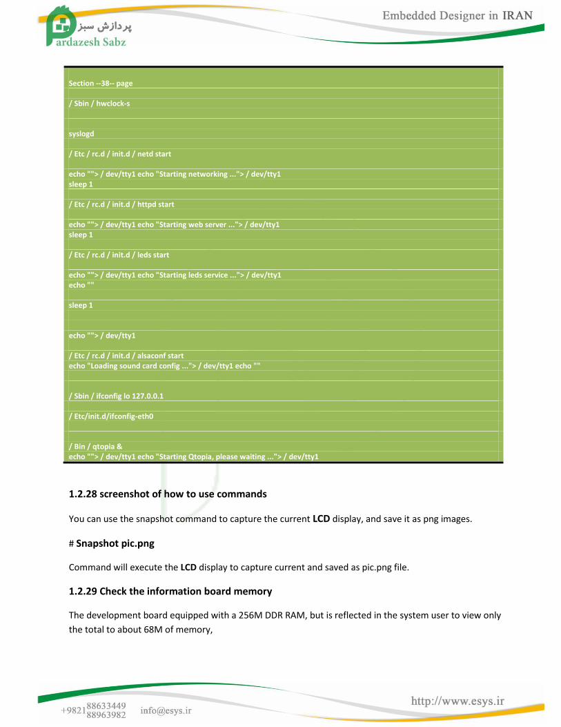
Section --38-- page / Sbin / hwclock-s syslogd / Etc / rc.d / init.d / netd start echo ""> / dev/tty1 echo "Starting networking ..."> / dev/tty1 sleep 1 / Etc / rc.d / init.d / httpd start echo ""> / dev/tty1 echo "Starting web server ..."> / dev/tty1 sleep 1 / Etc / rc.d / init.d / leds start echo ""> / dev/tty1 echo "Starting leds service ..."> / dev/tty1 echo "" sleep 1 echo ""> / dev/tty1 / Etc / rc.d / init.d / alsaconf start echo "Loading sound card config ..."> / dev/tty1 echo "" / Sbin / ifconfig lo 127.0.0.1 / Etc/init.d/ifconfig-eth0 / Bin / qtopia & echo ""> / dev/tty1 echo "Starting Qtopia, please waiting ..."> / dev/tty1
1.2.28 screenshot of how to use commands
You can use the snapshot command to capture the current LCD display, and save it as png images.
# Snapshot pic.png
Command will execute the LCD display to capture current and saved as pic.png file.
1.2.29 Check the information board memory
The development board equipped with a 256M DDR RAM, but is reflected in the system user to view only
the total to about 68M of memory,
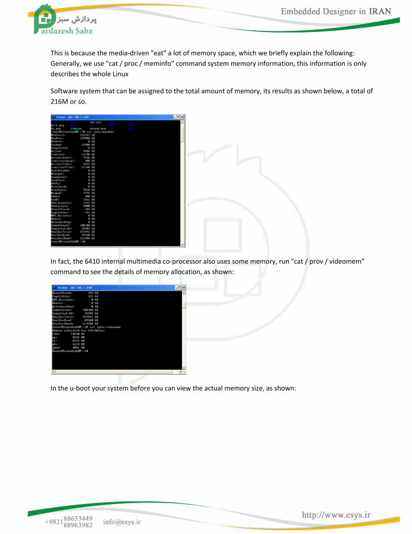
This is because the media-driven "eat" a lot of memory space, which we briefly explain the following:
Generally, we use "cat / proc / meminfo" command system memory information, this information is only
describes the whole Linux
Software system that can be assigned to the total amount of memory, its results as shown below, a total of
216M or so.
In fact, the 6410 internal multimedia co-processor also uses some memory, run "cat / prov / videomem"
command to see the details of memory allocation, as shown:
In the u-boot your system before you can view the actual memory size, as shown:
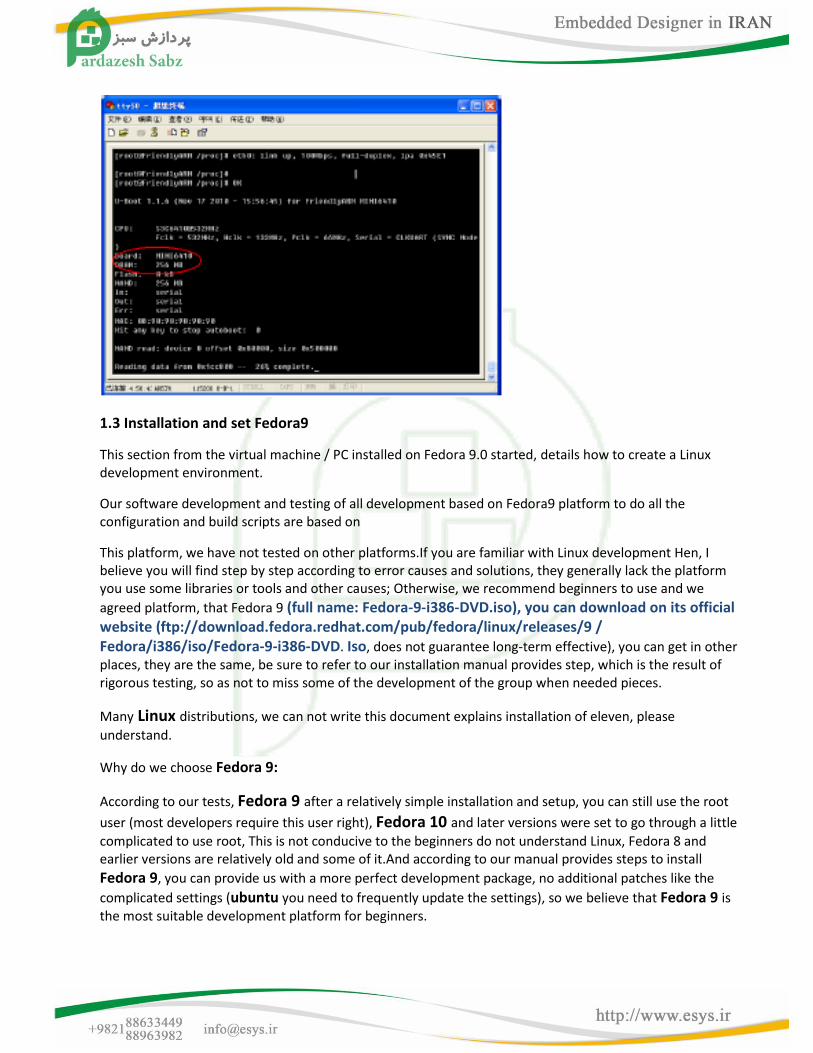
1.3 Installation and set Fedora9
This section from the virtual machine / PC installed on Fedora 9.0 started, details how to create a Linux development environment.
Our software development and testing of all development based on Fedora9 platform to do all the configuration and build scripts are based on
This platform, we have not tested on other platforms.If you are familiar with Linux development Hen, I believe you will find step by step according to error causes and solutions, they generally lack the platform you use some libraries or tools and other causes; Otherwise, we recommend beginners to use and we
agreed platform, that Fedora 9 (full name: Fedora-9-i386-DVD.iso), you can download on its official website (ftp://download.fedora.redhat.com/pub/fedora/linux/releases/9 / Fedora/i386/iso/Fedora-9-i386-DVD. Iso, does not guarantee long-term effective), you can get in other places, they are the same, be sure to refer to our installation manual provides step, which is the result of rigorous testing, so as not to miss some of the development of the group when needed pieces.
Many Linux distributions, we can not write this document explains installation of eleven, please
understand.
Why do we choose Fedora 9:
According to our tests, Fedora 9 after a relatively simple installation and setup, you can still use the root
user (most developers require this user right), Fedora 10 and later versions were set to go through a little
complicated to use root, This is not conducive to the beginners do not understand Linux, Fedora 8 and earlier versions are relatively old and some of it.And according to our manual provides steps to install
Fedora 9, you can provide us with a more perfect development package, no additional patches like the
complicated settings (ubuntu you need to frequently update the settings), so we believe that Fedora 9 is the most suitable development platform for beginners.
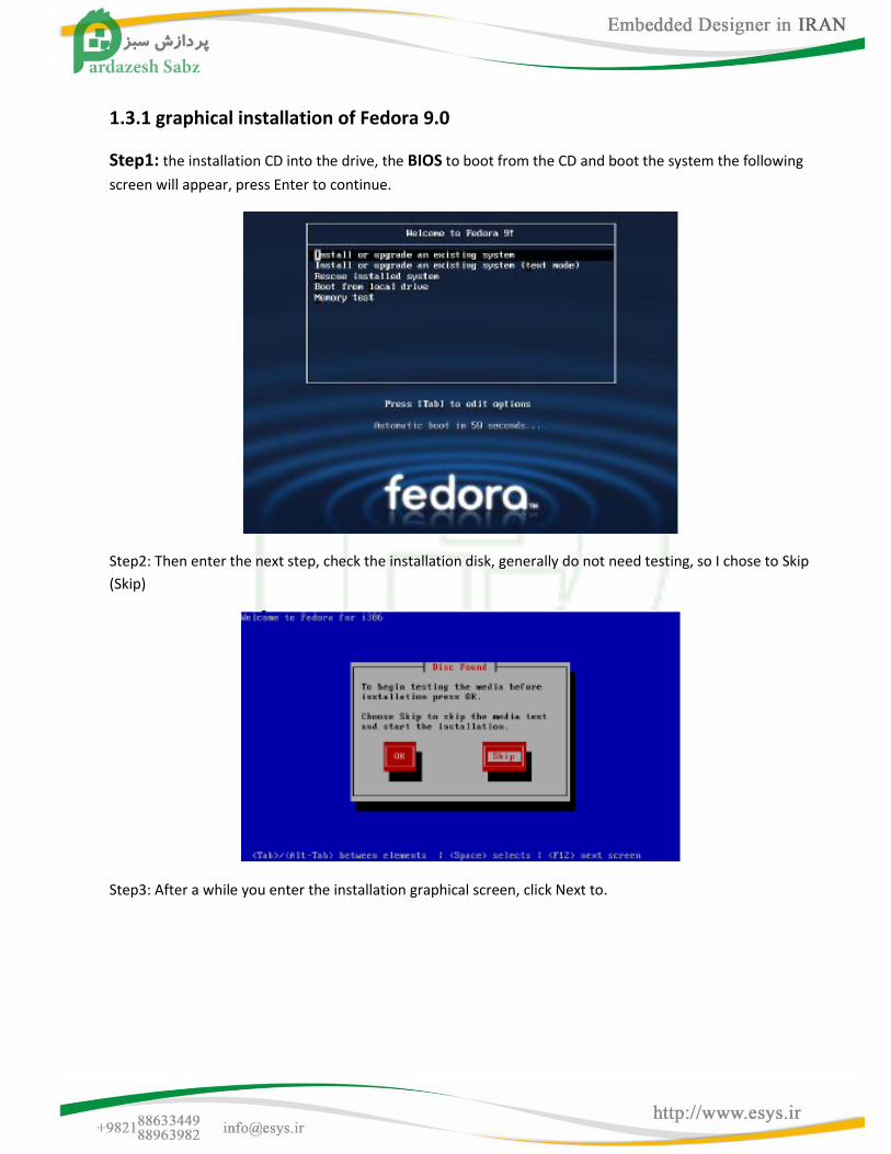
1.3.1 graphical installation of Fedora 9.0
Step1: the installation CD into the drive, the BIOS to boot from the CD and boot the system the following
screen will appear, press Enter to continue.
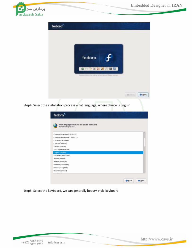
Step2: Then enter the next step, check the installation disk, generally do not need testing, so I chose to Skip
(Skip)
Step3: After a while you enter the installation graphical screen, click Next to.
Step4: Select the installation process what language, where choice is English
Step5: Select the keyboard, we can generally beauty-style keyboard
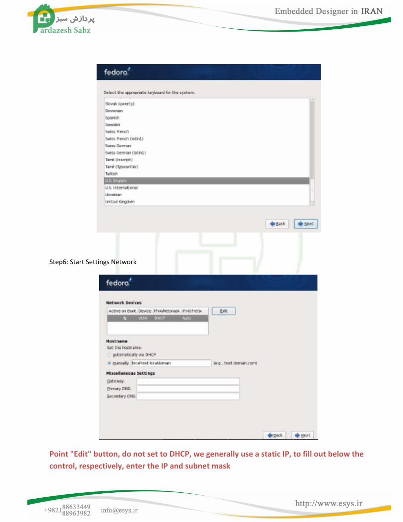
Step6: Start Settings Network
Point "Edit" button, do not set to DHCP, we generally use a static IP, to fill out below the
control, respectively, enter the IP and subnet mask

Click "OK" to return to begin setting up the machine name and the gateway, and DNS, etc.
Step7: Set time zone, if you do not use virtual machine installation, "System clock uses UTC" option can be
removed, as shown in Figure
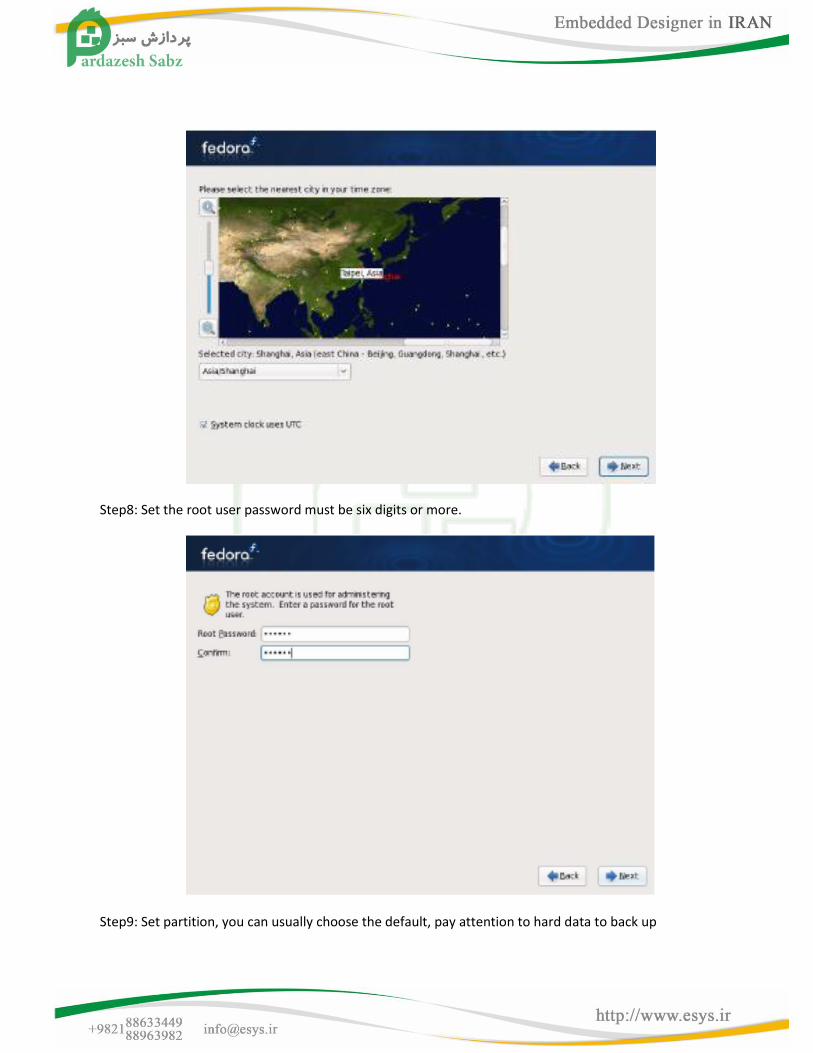
Step8: Set the root user password must be six digits or more.
Step9: Set partition, you can usually choose the default, pay attention to hard data to back up
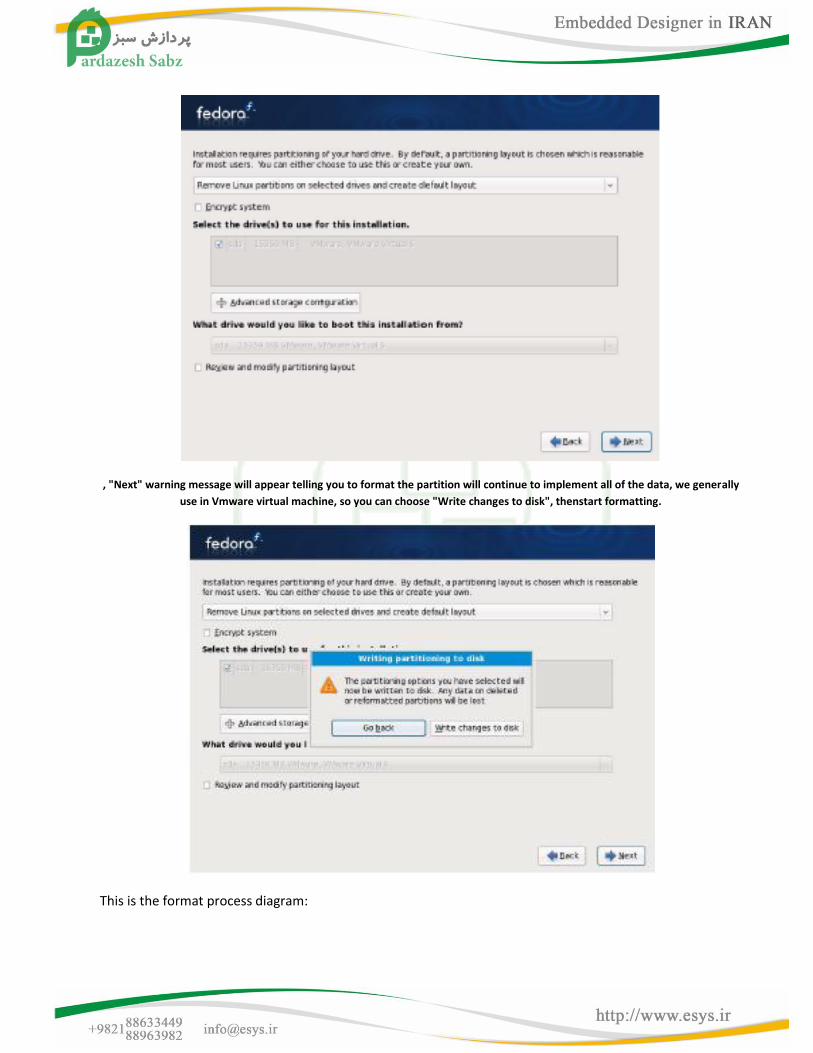
, "Next" warning message will appear telling you to format the partition will continue to implement all of the data, we generally
use in Vmware virtual machine, so you can choose "Write changes to disk", thenstart formatting.
This is the format process diagram:
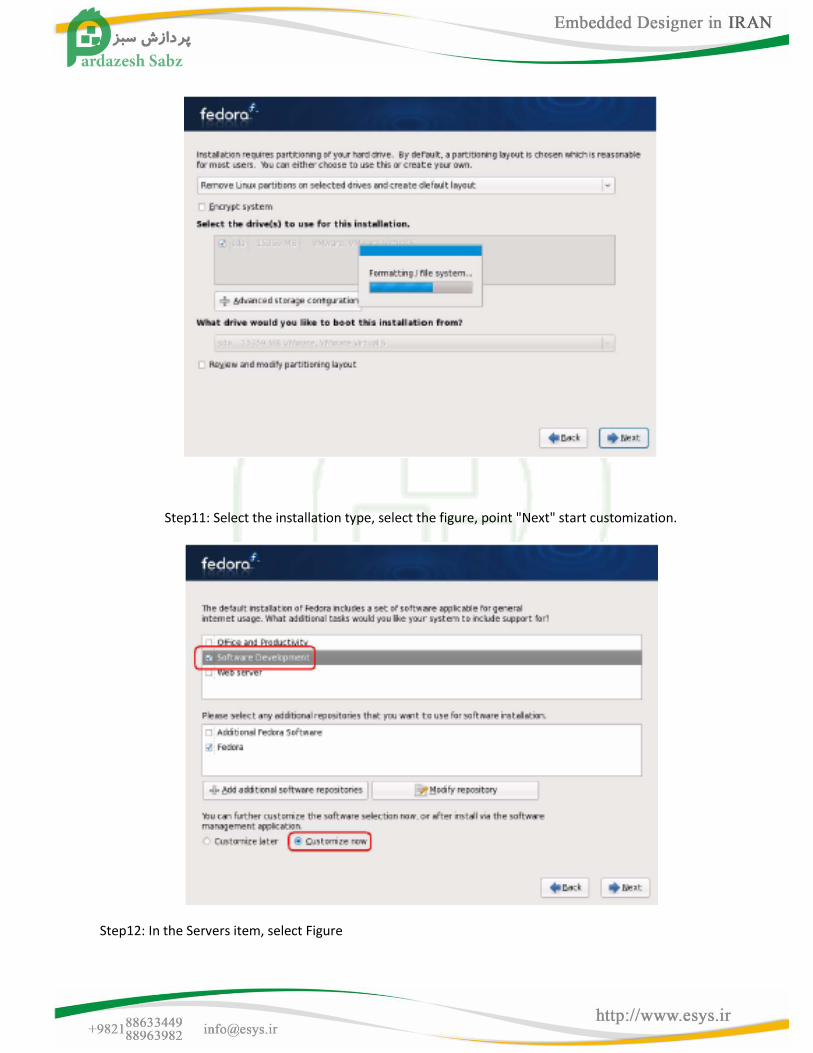
Step11: Select the installation type, select the figure, point "Next" start customization.
Step12: In the Servers item, select Figure
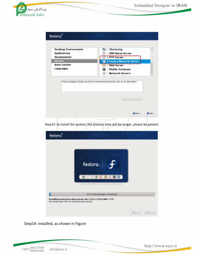
Step13: to install the system, the process time will be longer, please be patient.
Step14: installed, as shown in Figure
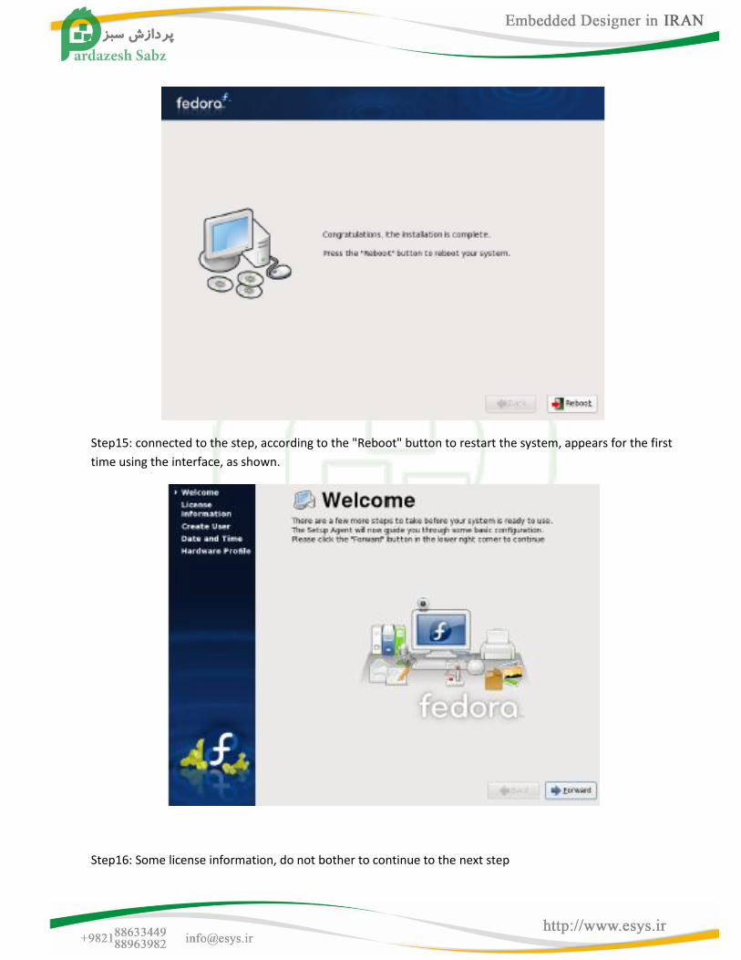
Step15: connected to the step, according to the "Reboot" button to restart the system, appears for the first
time using the interface, as shown.
Step16: Some license information, do not bother to continue to the next step
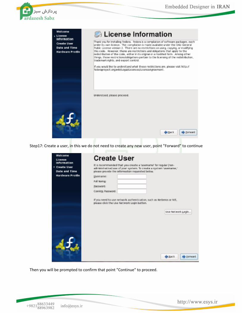
Step17: Create a user, in this we do not need to create any new user, point "Forward" to continue
Then you will be prompted to confirm that point "Continue" to proceed.
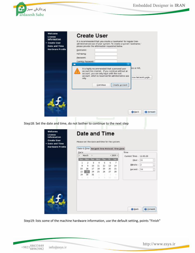
Step18: Set the date and time, do not bother to continue to the next step
Step19: lists some of the machine hardware information, use the default setting, points "Finish"
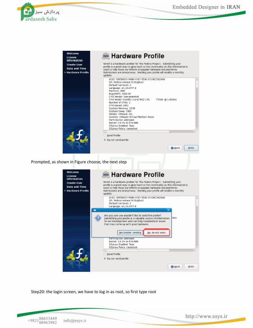
Prompted, as shown in Figure choose, the next step
Step20: the login screen, we have to log in as root, so first type root
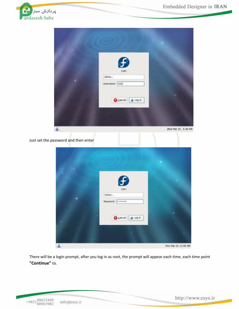
Just set the password and then enter
There will be a login prompt, after you log in as root, the prompt will appear each time, each time point
"Continue" to.
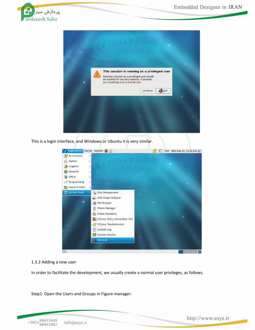
This is a login interface, and Windows or Ubuntu it is very similar.
1.3.2 Adding a new user
In order to facilitate the development, we usually create a normal user privileges, as follows.
Step1: Open the Users and Groups in Figure manager:
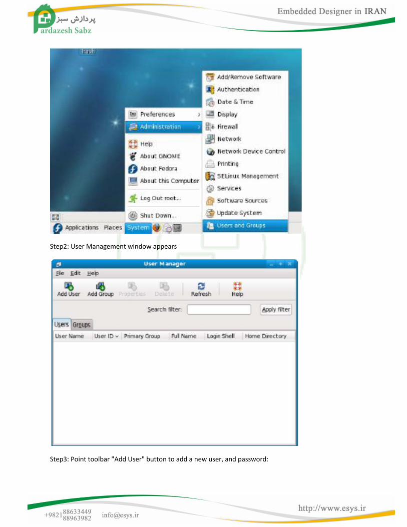
Step2: User Management window appears
Step3: Point toolbar "Add User" button to add a new user, and password:
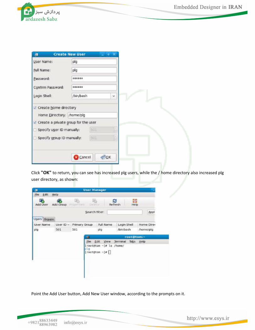
Click "OK" to return, you can see has increased plg users, while the / home directory also increased plg
user directory, as shown:
Point the Add User button, Add New User window, according to the prompts on it.
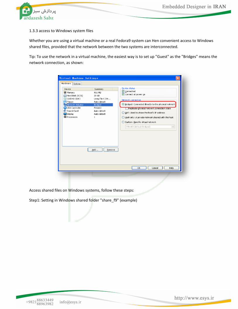
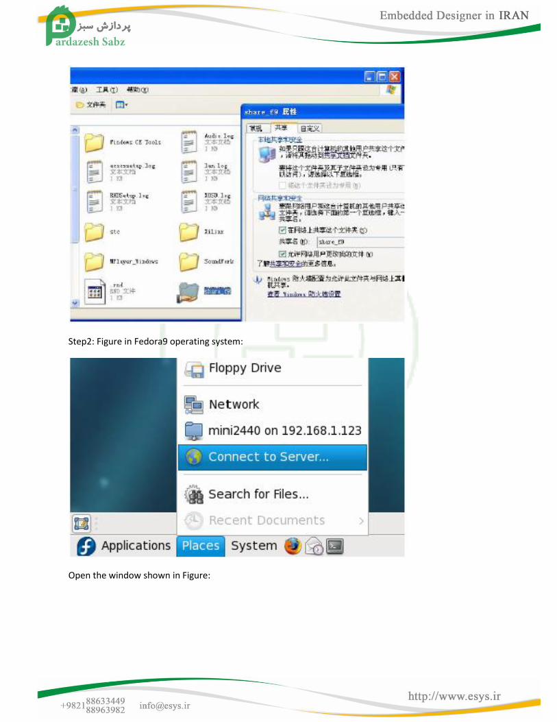
1.3.3 access to Windows system files
Whether you are using a virtual machine or a real Fedora9 system can Hen convenient access to Windows
shared files, provided that the network between the two systems are interconnected.
Tip: To use the network in a virtual machine, the easiest way is to set up "Guest" as the "Bridges" means the
network connection, as shown:
Access shared files on Windows systems, follow these steps:
Step1: Setting in Windows shared folder "share_f9" (example)
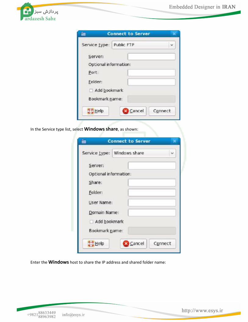
Step2: Figure in Fedora9 operating system:
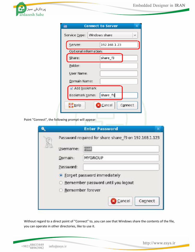
Open the window shown in Figure:
In the Service type list, select Windows share, as shown:
Enter the Windows host to share the IP address and shared folder name:
Point "Connect", the following prompt will appear:
Without regard to a direct point of "Connect" to, you can see that Windows share the contents of the file,
you can operate in other directories, like to use it.
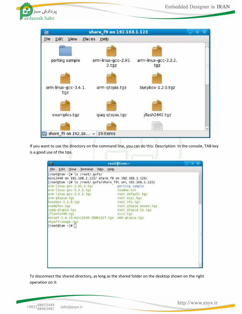
If you want to use the directory on the command line, you can do this: Description: In the console, TAB key
is a good use of the tips.
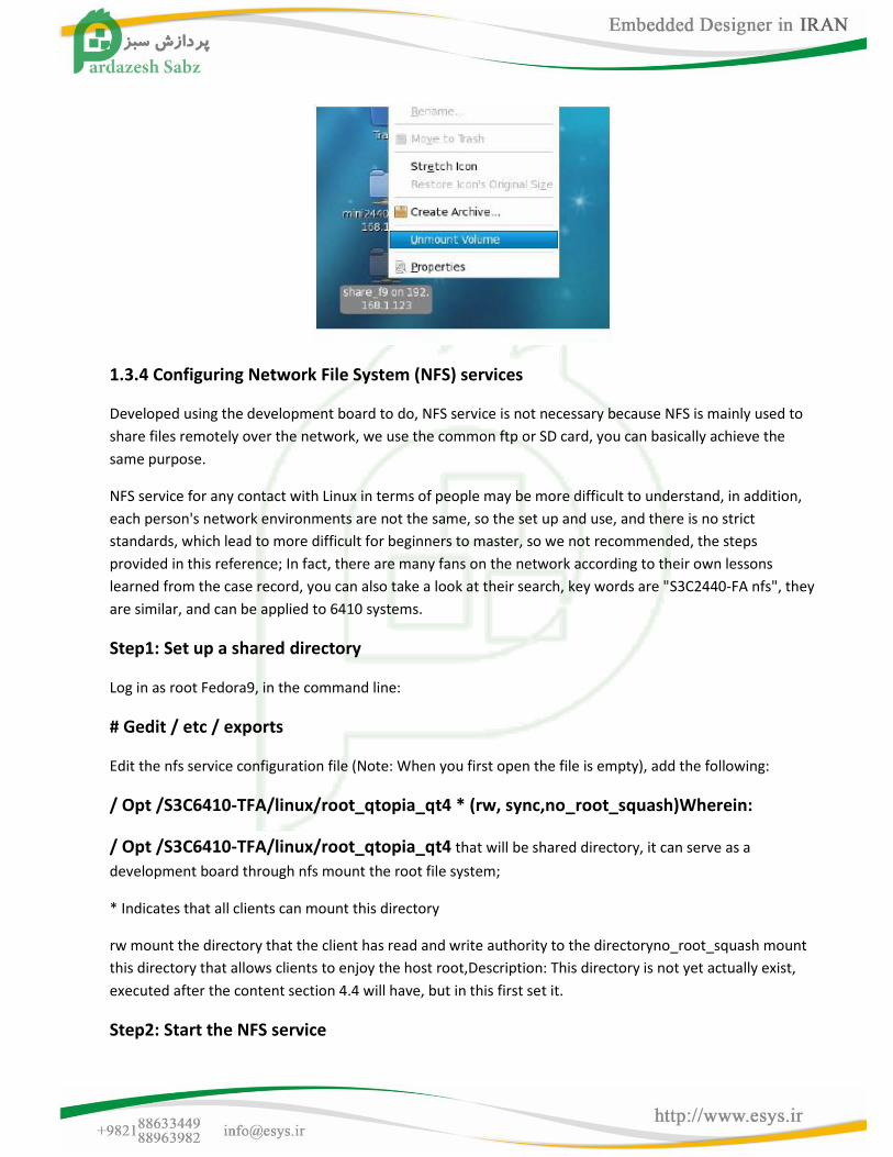
To disconnect the shared directory, as long as the shared folder on the desktop shown on the right
operation on it:
1.3.4 Configuring Network File System (NFS) services
Developed using the development board to do, NFS service is not necessary because NFS is mainly used to
share files remotely over the network, we use the common ftp or SD card, you can basically achieve the
same purpose.
NFS service for any contact with Linux in terms of people may be more difficult to understand, in addition,
each person's network environments are not the same, so the set up and use, and there is no strict
standards, which lead to more difficult for beginners to master, so we not recommended, the steps
provided in this reference; In fact, there are many fans on the network according to their own lessons
learned from the case record, you can also take a look at their search, key words are "S3C2440-FA nfs", they
are similar, and can be applied to 6410 systems.
Step1: Set up a shared directory
Log in as root Fedora9, in the command line:
# Gedit / etc / exports
Edit the nfs service configuration file (Note: When you first open the file is empty), add the following:
/ Opt /S3C6410-TFA/linux/root_qtopia_qt4 * (rw, sync,no_root_squash)Wherein:
/ Opt /S3C6410-TFA/linux/root_qtopia_qt4 that will be shared directory, it can serve as a
development board through nfs mount the root file system;
* Indicates that all clients can mount this directory
rw mount the directory that the client has read and write authority to the directoryno_root_squash mount
this directory that allows clients to enjoy the host root,Description: This directory is not yet actually exist,
executed after the content section 4.4 will have, but in this first set it.
Step2: Start the NFS service
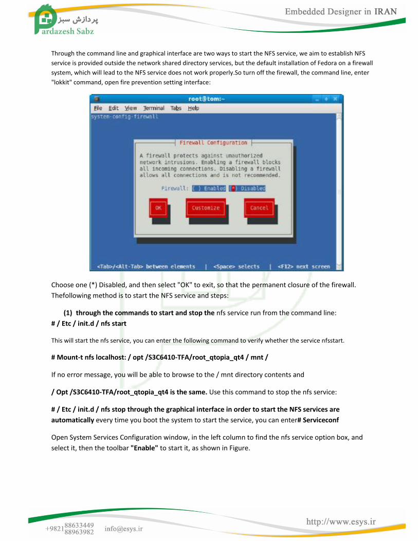
Through the command line and graphical interface are two ways to start the NFS service, we aim to establish NFS
service is provided outside the network shared directory services, but the default installation of Fedora on a firewall
system, which will lead to the NFS service does not work properly.So turn off the firewall, the command line, enter
"lokkit" command, open fire prevention setting interface:
Choose one (*) Disabled, and then select "OK" to exit, so that the permanent closure of the firewall.
Thefollowing method is to start the NFS service and steps:
(1) through the commands to start and stop the nfs service run from the command line:
# / Etc / init.d / nfs start
This will start the nfs service, you can enter the following command to verify whether the service nfsstart.
# Mount-t nfs localhost: / opt /S3C6410-TFA/root_qtopia_qt4 / mnt /
If no error message, you will be able to browse to the / mnt directory contents and
/ Opt /S3C6410-TFA/root_qtopia_qt4 is the same. Use this command to stop the nfs service:
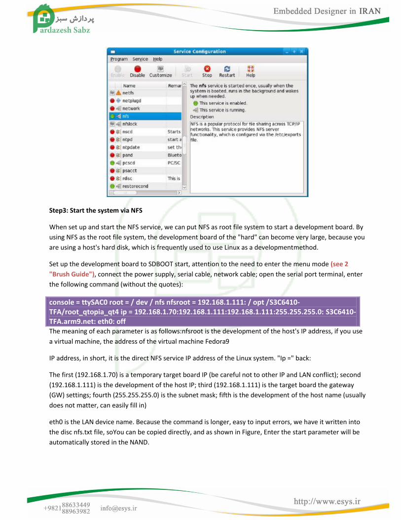
# / Etc / init.d / nfs stop through the graphical interface in order to start the NFS services are
automatically every time you boot the system to start the service, you can enter# Serviceconf
Open System Services Configuration window, in the left column to find the nfs service option box, and
select it, then the toolbar "Enable" to start it, as shown in Figure.
Step3: Start the system via NFS
When set up and start the NFS service, we can put NFS as root file system to start a development board. By
using NFS as the root file system, the development board of the "hard" can become very large, because you
are using a host's hard disk, which is frequently used to use Linux as a developmentmethod.
Set up the development board to SDBOOT start, attention to the need to enter the menu mode (see 2
"Brush Guide"), connect the power supply, serial cable, network cable; open the serial port terminal, enter
the following command (without the quotes):
console = ttySAC0 root = / dev / nfs nfsroot = 192.168.1.111: / opt /S3C6410-TFA/root_qtopia_qt4 ip = 192.168.1.70:192.168.1.111:192.168.1.111:255.255.255.0: S3C6410-TFA.arm9.net: eth0: off The meaning of each parameter is as follows:nfsroot is the development of the host's IP address, if you use
a virtual machine, the address of the virtual machine Fedora9
IP address, in short, it is the direct NFS service IP address of the Linux system. "Ip =" back:
The first (192.168.1.70) is a temporary target board IP (be careful not to other IP and LAN conflict); second
(192.168.1.111) is the development of the host IP; third (192.168.1.111) is the target board the gateway
(GW) settings; fourth (255.255.255.0) is the subnet mask; fifth is the development of the host name (usually
does not matter, can easily fill in)
eth0 is the LAN device name. Because the command is longer, easy to input errors, we have it written into
the disc nfs.txt file, soYou can be copied directly, and as shown in Figure, Enter the start parameter will be
automatically stored in the NAND.
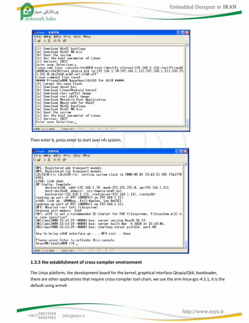
Then enter b, press enter to start over nfs system.
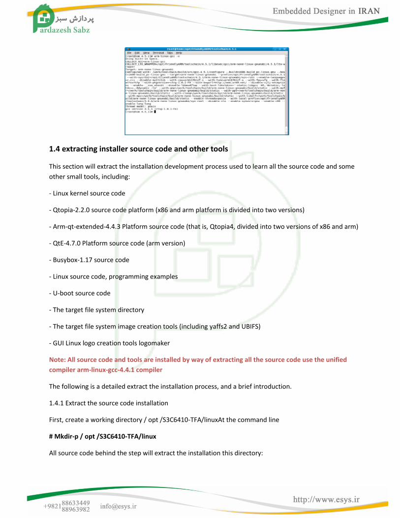
1.3.5 the establishment of cross-compiler environment
The Linux platform, the development board for the kernel, graphical interface Qtopia/Qt4, bootloader,
there are other applications that require cross-compiler tool chain, we use the arm-linux-gcc-4.5.1, it is the
default using armv6

Instruction set, hardware floating point support, the following is the detailed steps to install it.
Step1: the CD-ROM Linux directory arm-linux-gcc-4.5.1-v6-vfp-20101103.tgz copy Fedora9
A directory such as tmp /, then go to the directory, perform decompression command:
# Cd / tmp
# Tar xvzf arm-linux-gcc-4.5.1-v6-vfp-20101103.tgz-C /
Note: C with a trailing space, and C is capitalized, it is the English word "Change" the first letter, in the
meaning of this is to change the directory.
Execute the command, will arm-linux-gcc installed to / opt /toolschain/4.5.1 directory.
Step2: the compiler to add the path system environment variable, run the command
# Gedit / root / .bashrc
Edit / root / .bashrc file, pay attention to "bashrc" in front of a ".", The last act to modify export PATH = $
PATH: / opt /toolschain/4.5.1/bin, attention paths must write, or else will not be effective.
Figure, save and exit.
Log system (without reboot the machine to start -> logout can be), so the above settings to take effect, at
the command line
arm-linux-gcc-v, the following message will appear, indicating that cross-compiler environment has been
successfully installed.
1.4 extracting installer source code and other tools
This section will extract the installation development process used to learn all the source code and some
other small tools, including:
- Linux kernel source code
- Qtopia-2.2.0 source code platform (x86 and arm platform is divided into two versions)
- Arm-qt-extended-4.4.3 Platform source code (that is, Qtopia4, divided into two versions of x86 and arm)
- QtE-4.7.0 Platform source code (arm version)
- Busybox-1.17 source code
- Linux source code, programming examples
- U-boot source code
- The target file system directory
- The target file system image creation tools (including yaffs2 and UBIFS)
- GUI Linux logo creation tools logomaker
Note: All source code and tools are installed by way of extracting all the source code use the unified
compiler arm-linux-gcc-4.4.1 compiler
The following is a detailed extract the installation process, and a brief introduction.
1.4.1 Extract the source code installation
First, create a working directory / opt /S3C6410-TFA/linuxAt the command line
# Mkdir-p / opt /S3C6410-TFA/linux
All source code behind the step will extract the installation this directory:
(1) ready for the Linux source code package
In Fedora9 system / tmp directory, create a temporary directory / tmp / linux
# Mkdir / tmp / linuxLinux directory in the CD all the files are copied to / tmp / linux directoryDescription: This is to unify thefollowing steps, in fact, you can use a different directory, you can alsodirectly from theExtract the installation CD.
(2) Extract the installation of U-boot source code in the working directory /opt /S3C6410-TFA/linux perform:
# Cd / opt /S3C6410-TFA/linux # Tar xvzf / tmp / linux / u-boot-S3C6410-TFA-20101106.tar.gz Will create the build u-boot-S3C6410-TFA directory, which contains a complete description of U-bootsourcecode: 20101106 Release Date our logo, to the actual date of the CD suffix shall prevail.
(3) Extract the Linux kernel source code installed in the working directory /opt /S3C6410-TFA/linux perform:
# Cd / opt /S3C6410-TFA/linux # Tar xvzf / tmp / linux / linux-2.6.36-20101115.tar.gz Will create a generation linux-2.6.36 directory, which contains the complete kernel sourcecodeDescription: 20101115 Date of issue of our logo, to the actual date of the CD suffix shallprevail.
(4) Extract the target file system installation execute the following command:
# Cd / opt /S3C6410-TFA/linux # Tar xvzf / tmp / linux / rootfs_qtopia_qt4-20101120.tgz Directory will be created to generate rootfs_qtopia_qt4Description: 20101120 Date of issue of our logo,to the actual date of the CD suffix shall prevail.
(5) extract the embedded graphics system installed qtopia source code in the working directory /opt /S3C6410-TFA/linux perform:
# Cd / opt /S3C6410-TFA/linux # Tar xvzf / tmp / linux / x86-qtopia-20100420.tar.gz # Tar xvzf / tmp / linux / arm-qtopia-20101105.tar.gz Will create x86-qtopia and arm-qtopia two directories, and includes all of the corresponding sourcecode.Description: x86-qtopia and arm-qtopia back there may be a date suffix, it is issued or updated on our logo, to the actual date of the CD suffix shall prevail.Source code package also includes an embedded browser konquor the source code.In addition this source code package compared to Qt's original version has been patched, and made many improvements, they are source code form, we will not repeat all, and self-interested more.
(6) Extract the installation of embedded graphics system qt-extended-4.4.3 source codeThe code.In
the working directory / opt /S3C6410-TFA/linux perform:
# Cd / opt /S3C6410-TFA/linux
# Tar xvzf / tmp / linux / x86-qt-extended-4.4.3-20101003.tgz
# Tar xvzf / tmp / linux / arm-qt-extended-4.4.3-20101105.tgz
Will create x86-qt-extended-4.4.3 and arm-qt-extended-4.4.3 two directories, and includes all ofthecorresponding sourceDescription: x86-qt-extended-4.4.3 and arm-qt-extended-4.4.3 after the date suffix may be, it isThe dateof issue or update their logo, to the actual date of the CD suffix shall prevail. In addition, to use this source code package compared to Qt's original versionhasbeen played upDing, and made some improvements, they are source code form, we will not repeatall, interested and self-comparison.
(7) extract the installation QtE-4.7.0 source code in the working directory /opt /S3C6410-TFA/linux perform:
# Cd / opt /S3C6410-TFA/linux
# Tar xvzf / tmp/linux/x86-qte-4.6.1-20100516.tar.gz
# Tar xvzf / tmp / linux / arm-qte-4.7.0-20101105.tar.gz
Will create x86-qte-4.6.1 and two arm-qte-4.7.0 directory, and contains all the correspondingsourcecode.Description: x86-qte and arm-qte archive dates back suffix may be, it is our issue or updatedate, the actual date of the CD suffix shall prevail.One x86-qte-4.6.1 is mainly created Creatordevelopment platform, slightly lower version will not affect development.
(8) Extract the source code installed busyboxBusybox
is a lightweight tool for linux command set is usedin this version of busybox-1.13.3.Users can download the latest version from their official website(http://www.busybox.net).In the working directory / opt/ /S3C6410-TFA/linux perform:
# Cd / opt /S3C6410-TFA/linux
# Tar xvzf / tmp / linux / busybox-1.17.2-20101120.tgz
Busybox-1.17.2 directory will be created, containing the appropriate version of the full sourcecode.Note:, we made a default configuration file fa.config.
(9) Extract the installation of Linux sample program performs the following command:
# Cd / opt /S3C6410-TFA/linux
# Tar xvzf / tmp / linux / examples-S3C6410-TFA-20101110.tgz
Will create the examples directory, and include beginner linux programming code examples.Description: 20101110 Date of issue of our logo, to the actual date of the CD suffix shall prevail.The code examplesdirectory are a set self-development, and provide all the source code, they are a smallnumber of command-line program.
1.4.2 Extract to create the target file system

According to the connection touch screen configuration, for the convenience of users, we haveproduced two target file system archive:
rootfs_qtopia_qt4-20101120.tgz
rootfs_qtopia_qt4-s-20101120.tgz
Of which: with "-s" representation for a professional serial LCD touch-screen controller package, it is suitable for largeSize of the four-wire resistive touch screen, will achieve better results; without "-s" representation of the ARM itself is touch-screen controller, or first-line touch screen (the first run will automatically recognize).Execute the following command:
# Cd / opt /S3C6410-TFA/linux
# Tar xvzf / tmp / linux / rootfs_qtopia_qt4-20101120.tgz
# Tar xvzf / tmp / linux / rootfs_qtopia_qt4-s-20101120.tgz
Will create rootfs_qtopia_qt4 and rootfs_qtopia_qt4-s two directories, the directory and file systemused by the target board is exactly the same content.Description: 20101120 Release Date our logo, to theactual date of the CD suffix shall prevail, the file system contains a front you see qtopia-2.2.0, Qtopia4and QtE-4.7.0 test software, busybox, there are commonly used command-line tools, andbefore, it has the following features:
- Automatic Identification start or local start NFS - Automatic recognition of the connection of the output display module is connected with a touchscreen, to determine first whether to start using the correction.If not connected, it will automaticallyenter the system, using the mouse; otherwise it will be touch screen calibration. - Automatic Identification ordinary or high-speed SD card (maximum support 32G) and USB flash drives - Auto-detect USB mouse or touch screen - Support for USB mouse and touch-screen co-existence (starting from the Linux-2.6.36 support) 1.4.3 Extract installation file system image tool
We should all write the target file system development board, in general, need to first create the target file system directory into a single image file or copy to programming, Linux kernel boot time, generally based on the command line parameters the system hung in different formats such as yaffs2, ubifs, ext2, nfs, etc.They are generally small command line program.
For 64M or 128M/256M/512M/1GB De S3C2440-FA/mcro2440, respectively, two sets of production tools: mkyaffs2image and mkyaffs2image-128M.Which is produced for mkyaffs2image 64M version of the file system image tool that follows the previous name; mkyaffs2image-128M is produced for128M/256M/512M/1GB version of the file system image tools, in order to facilitate the distinction, we named it this. For the 6410 system, we did not make 64M version, so you can follow the system used by the 2440mkyaffs2image-128MUBIFS is nearly two years, another popular memory for embedded system file system format, UBIFS official use of the tool is more complex, and are a lot of parameters and procedures, in order to facilitate use, we also designed a mkubimage
Another mkext3image, it used to be made into a single target file system EXT3-image file, so that you can in
ordinary FAT32/FAT format SD card to install a Linux system using a variety of classes, only a single system

image file corresponding copied to the SD card can be, this is no longer required a very complex
procedure.We put these little tools collectively referred to as mktools, following its installation steps: Run
the following command:# Tar xvzf / tmp / linux / mktools.tar.gz-C /
Will be in / usr / sbin directory to create generation mkyaffs2image, mkyaffs2image-128M,
mkubimage,mkext3image
Note: C is capitalized, C with a trailing space, C is to change the installation directory extract the meaning of
Note: If you previously installed S3C2440-FA use mkyaffs2image family of tools, they will be overwritten,
Do not worry, they function the same.
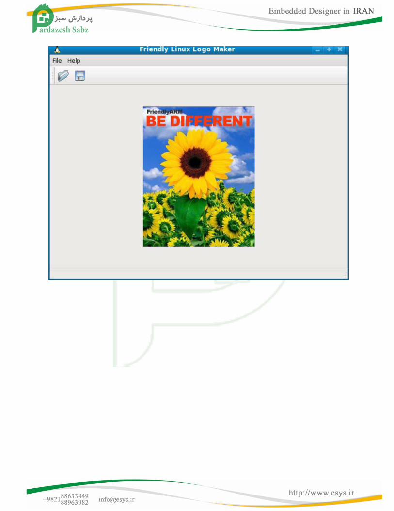
1.4.4 extracting installer LogoMaker
LogoMaker is a set developed a Linux Logo simple authoring tools, there are many online information on
how to use the command-line tool to bmp, jpg, png format images converted to Linux Logo file, In this we
have designed a graphical version, which is based Fedora9 development.Execute the following command:
# Tar xvzf / tmp / linux / logomaker.tgz-C /
Note: C is capitalized, C with a trailing space, C is to change the installation directory extract the meaning of
Description: The implementation of the above command, LogoMaker will be installed to / usr / sbin
directory, it has only one file, after installation at the command line enter the following interface logomaker
may, in a later section we will introduce how to use it:
1.5 Configure and compile U-boot
Samsung has been good for the 6410 transplant U-boot, and support for USB download, Nand start, etc., it is
open source, nothing more.On this basis, we are on the U-boot to do a lot of improvements:
- Increase the download menu, similar to the USB download menu Superboot - Increase the SD card boot configuration - Support for direct download programming yaffs2 file system image - Support for programming WindowsCE BootLoader of Nboot - Support for image feature programming WindowsCE - Support for burning single file image files, the program is commonly referred to as bare metal - Support for return to the original shell - Added support for 256M DDR RAM Here we describe the configuration and compile it and use it. 1.5.1 Configuring the Compile NAND boot support for the U-boot
Description: According to the different development board memory (DDR RAM) capacity, need to use a different
U-boot configuration items. To compile for 128M memory, U-boot, follow these steps:
U-boot code into the source directory, run:
# Cd / opt /S3C6410-TFA/linux/u-boot-S3C6410-TFA
# Make S3C6410-TFA_nand_config-ram128; make
Configuration and in the current directory will be compiled to support Nand start U-boot.bin, use the SD card or
USB download to Nand Flash can be used, see "Brush Guide" CD-ROM images / linux directory has been provided
compiled the file, for ease of distinction, we rename it to u-boot_nand-ram128.bin
To compile for 256M memory U-boot, follow these steps: Go to U-boot source directory, run:
# Cd / opt /S3C6410-TFA/linux/u-boot-S3C6410-TFA
# Make S3C6410-TFA_nand_config-ram256; make
Configuration and in the current directory will be compiled to support Nand start U-boot.bin, use the SD card or
USB download to Nand Flash can be used, see "Brush Guide" CD-ROM images / linux directory has been provided
compiled the file, for ease of distinction, we rename it to u-boot_nand-ram256.bin
1.5.2 SD card support for configuring compile U-boot boot
Description: According to the different development board memory (DDR RAM) capacity, need to use a different
U-boot configuration items. To compile for 128M memory, U-boot, follow these steps:
U-boot code into the source directory, run:
# Cd / opt /S3C6410-TFA/linux/u-boot-S3C6410-TFA
# Make S3C6410-TFA_sd_config-ram128; make
In the current directory will be compiled with support for SD configuration and start U-boot.bin, using SD-
Flasher.exe tool it programmed into the SD card, set development board from the start to use the SD card, you
can refer to 2.2 sections of the steps, simply one of the Superboot.bin to U-boot.bin on it.CD images / linux
directory has been compiled in the document provided, in order to facilitate the distinction, we rename it to u-
boot_sd-ram128.bin
To compile for 256M memory U-boot, follow these steps: Go to U-boot source directory, run:
# Cd / opt /S3C6410-TFA/linux/u-boot-S3C6410-TFA
# Make S3C6410-TFA_sd_config-ram256; make
In the current directory will be compiled with support for SD configuration and start the U-boot.bin, using the
SD-Flasher.exe tool programmed it to an SD card, set the development board can be used starting from the SD
card, you can refer to 2.2 sections of the steps, simply one of the Superboot.bin to U-boot.bin on it.CD images /
linux directory has been compiled in the document provided, in order to facilitate the distinction, we rename it
to u-boot_sd-ram256.bin
1.5.3 U-boot instructions
Unfinished
1.6 Configure and compile the kernel (Kernel)
In order to facilitate the user to compile a file and CD burning is fully consistent core, we focused on different
LCD output separately the corresponding kernel configuration file:
config_S3C6410-TFA_x35 - for Sony 3.5 "LCD, a resolution of 240x320 config_S3C6410-TFA_n43 - for NEC4.3"
LCD, a resolution of 480x272 config_S3C6410-TFA_l80 - for Sharp 8 "(or compatible) LCD, a resolution of 640x480
config_S3C6410-TFA_a70 - for 7-inch true color screen, a resolution of 800x480 config_S3C6410-
TFA_vga1024x768 - for resolution of 1024x768 VGA output module adapter plate config_S3C6410-
TFA_vga800x600 - for the VGA resolution of 800x600 output module adapter plate config_S3C6410-
TFA_vga640x480 - for the VGA resolution of 640x480 output module adapter plate config_S3C6410-
TFA_ezvga800x600 - VGA adapter plate for easy output resolution of 800x600
Default the following command to compile the kernel configuration file config_n43
# Cp config_S3C6410-TFA_n43. Config; Note: n43 with a trailing space, then there is a "."Beginning of the config
# Make zImage; start compiling the kernel, you can directly use the make command
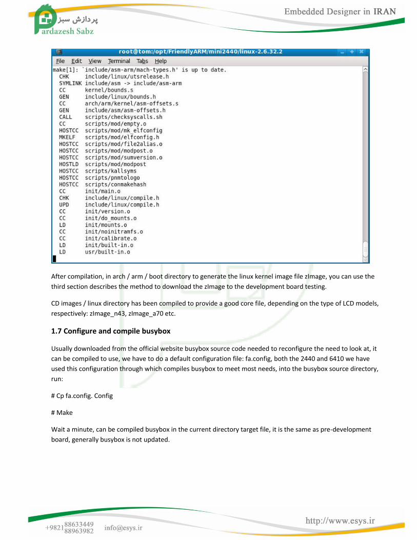
After compilation, in arch / arm / boot directory to generate the linux kernel image file zImage, you can use the
third section describes the method to download the zImage to the development board testing.
CD images / linux directory has been compiled to provide a good core file, depending on the type of LCD models,
respectively: zImage_n43, zImage_a70 etc.
1.7 Configure and compile busybox
Usually downloaded from the official website busybox source code needed to reconfigure the need to look at, it
can be compiled to use, we have to do a default configuration file: fa.config, both the 2440 and 6410 we have
used this configuration through which compiles busybox to meet most needs, into the busybox source directory,
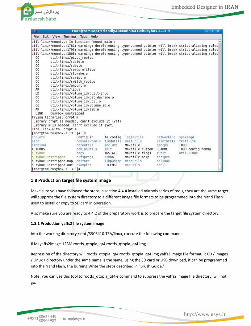
run:
# Cp fa.config. Config
# Make
Wait a minute, can be compiled busybox in the current directory target file, it is the same as pre-development
board, generally busybox is not updated.
1.8 Production target file system image
Make sure you have followed the steps in section 4.4.4 installed mktools series of tools, they are the same target
will suppress the file system directory to a different image file formats to be programmed into the Nand Flash
used to install or copy to SD card in operation.
Also make sure you are ready to 4.4.2 of the preparatory work is to prepare the target file system directory.
1.8.1 Production yaffs2 file system image
Into the working directory / opt /S3C6410-TFA/linux, execute the following command:
# Mkyaffs2image-128M rootfs_qtopia_qt4 rootfs_qtopia_qt4.img
Repression of the directory will rootfs_qtopia_qt4 rootfs_qtopia_qt4.img yaffs2 image file format, it CD / images
/ Linux / directory under the same name is the same, using the SD card or USB download, it can be programmed
into the Nand Flash, the burning Write the steps described in "Brush Guide."
Note: You can use this tool to rootfs_qtopia_qt4-s command to suppress the yaffs2 image file directory, will not
go.

1.8.2 Production ubifs file system image
Into the working directory / opt /S3C6410-TFA/linux, execute the following command:
# Mkyaffs2image-128M rootfs_qtopia_qt4 rootfs_qtopia_qt4.ubi
Repression of the directory will rootfs_qtopia_qt4 rootfs_qtopia_qt4.ubi UBIFS image file format, it CD / images
/ Linux / directory under the same name is the same, using the SD card or USB download, it can be programmed
into the Nand Flash, the burning Write the steps described in "Brush Guide."
Note: You can use this tool to rootfs_qtopia_qt4-s command to suppress the ubifs image file directory, will not
go
1.8.3 create ext3 file system image
Into the working directory / opt /S3C6410-TFA/linux, execute the following command:
# Mkext3image-128M rootfs_qtopia_qt4 rootfs_qtopia_qt4.ext3
Suppressed as EXT3 will rootfs_qtopia_qt4 catalog image file format rootfs_qtopia_qt4.ext3 it and CD / images /
Linux / directory under the same name is the same, the instructions refer to section 3.3, copy it into the SD card
you can use it running system.
Note: You can use this tool to rootfs_qtopia_qt4-s command to suppress the ext3 image file directory, will not go
1.9 Examples of embedded Linux applications
This section embedded Linux development through the most simple example, how to write and compile Linux
applications, and download to development board up and running.
If you have already performed the steps in section 4.4.1, you can / opt /S3C6410-TFA/examples
Directory to find the following sample source code, the actual number may be more, just choose a few examples
of the following for guidance.
Embedded Linux is rich in resources, we can not introduce into every detail, this paper aims to provide some of
the embedded
Linux often used method for you to open the door to a wonderful world.
Note: The following example program uses the compiler to arm-linux-gcc-4.5.1-v6-vfp, if you use other versions
of the cross-compiler, there may not be compiled to run on the development board.
To check the cross-compiler version of the type, can be run in a terminal command: arm-linux-gcc-v, as shown in
Figure
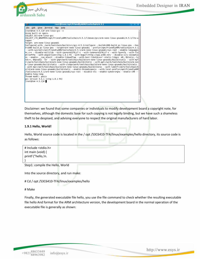
Disclaimer: we found that some companies or individuals to modify development board a copyright note, for
themselves, although the domestic base for such copying is not legally binding, but we have such a shameless
theft to be despised, and advising everyone to respect the original manufacturers of hard labor.
1.9.1 Hello, World!
Hello, World source code is located in the / opt /S3C6410-TFA/linux/examples/hello directory, its source code is
as follows:
# Include <stdio.h> int main (void) { printf ("hello,!n. }
Step1: compile the Hello, World
Into the source directory, and run make:
# Cd / opt /S3C6410-TFA/linux/examples/hello
# Make
Finally, the generated executable file hello, you use the file command to check whether the resulting executable
file hello And format for the ARM architecture version, the development board in the normal operation of the
executable file is generally as shown:
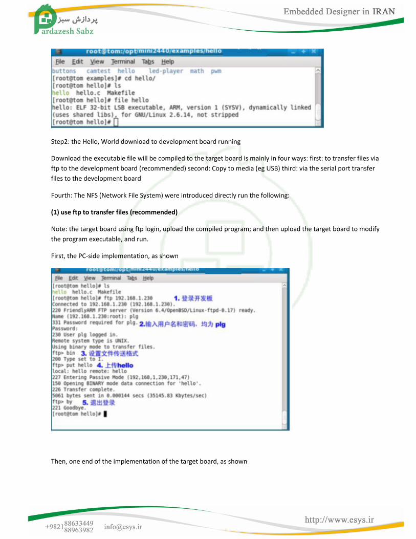
Step2: the Hello, World download to development board running
Download the executable file will be compiled to the target board is mainly in four ways: first: to transfer files via
ftp to the development board (recommended) second: Copy to media (eg USB) third: via the serial port transfer
files to the development board
Fourth: The NFS (Network File System) were introduced directly run the following:
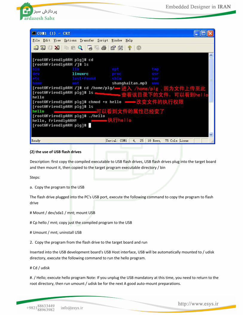
(1) use ftp to transfer files (recommended)
Note: the target board using ftp login, upload the compiled program; and then upload the target board to modify
the program executable, and run.
First, the PC-side implementation, as shown
Then, one end of the implementation of the target board, as shown
(2) the use of USB flash drives
Description: first copy the compiled executable to USB flash drives, USB flash drives plug into the target board
and then mount it, then copied to the target program executable directory / bin
Steps:
a. Copy the program to the USB
The flash drive plugged into the PC's USB port, execute the following command to copy the program to flash
drive
# Mount / dev/sda1 / mnt; mount USB
# Cp hello / mnt; copy just the compiled program to the USB
# Umount / mnt; uninstall USB
2. Copy the program from the flash drive to the target board and run
Inserted into the USB development board's USB Host interface, USB will be automatically mounted to / udisk
directory, execute the following command to run the hello program.
# Cd / udisk
#. / Hello; execute hello program Note: If you unplug the USB mandatory at this time, you need to return to the
root directory, then run umount / udisk be for the next A good auto-mount preparations.
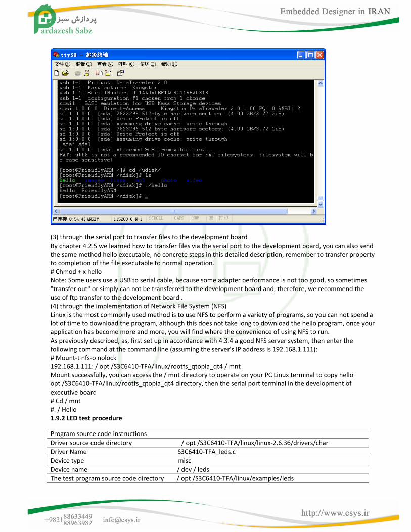
(3) through the serial port to transfer files to the development board By chapter 4.2.5 we learned how to transfer files via the serial port to the development board, you can also send the same method hello executable, no concrete steps in this detailed description, remember to transfer property to completion of the file executable to normal operation. # Chmod + x hello Note: Some users use a USB to serial cable, because some adapter performance is not too good, so sometimes "transfer out" or simply can not be transferred to the development board and, therefore, we recommend the use of ftp transfer to the development board . (4) through the implementation of Network File System (NFS) Linux is the most commonly used method is to use NFS to perform a variety of programs, so you can not spend a lot of time to download the program, although this does not take long to download the hello program, once your application has become more and more, you will find where the convenience of using NFS to run. As previously described, as, first set up in accordance with 4.3.4 a good NFS server system, then enter the following command at the command line (assuming the server's IP address is 192.168.1.111): # Mount-t nfs-o nolock 192.168.1.111: / opt /S3C6410-TFA/linux/rootfs_qtopia_qt4 / mnt Mount successfully, you can access the / mnt directory to operate on your PC Linux terminal to copy hello opt /S3C6410-TFA/linux/rootfs_qtopia_qt4 directory, then the serial port terminal in the development of executive board # Cd / mnt #. / Hello 1.9.2 LED test procedure
Program source code instructions
Driver source code directory / opt /S3C6410-TFA/linux/linux-2.6.36/drivers/char
Driver Name S3C6410-TFA_leds.c
Device type misc
Device name / dev / leds
The test program source code directory / opt /S3C6410-TFA/linux/examples/leds
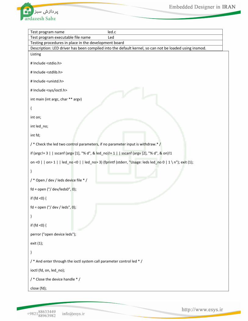
Test program name led.c
Test program executable file name Led
Testing procedures in place in the development board
Description: LED driver has been compiled into the default kernel, so can not be loaded using insmod.
Listing
# Include <stdio.h>
# Include <stdlib.h>
# Include <unistd.h>
# Include <sys/ioctl.h>
int main (int argc, char ** argv)
{
int on;
int led_no;
int fd;
/ * Check the led two control parameters, if no parameter input is withdraw.* /
if (argc!= 3 | | sscanf (argv [1], "% d", & led_no)!= 1 | | sscanf (argv [2], "% d", & on)!1
on <0 | | on> 1 | | led_no <0 | | led_no> 3) {fprintf (stderr, "Usage: leds led_no 0 | 1 \ n"); exit (1);
}
/ * Open / dev / leds device file * /
fd = open ("/ dev/leds0", 0);
if (fd <0) {
fd = open ("/ dev / leds", 0);
}
if (fd <0) {
perror ("open device leds");
exit (1);
}
/ * And enter through the ioctl system call parameter control led * /
ioctl (fd, on, led_no);
/ * Close the device handle * /
close (fd);
return 0;
}
You can follow the above steps to compile the hello program led executable file, then downloaded to the
development board to run it.
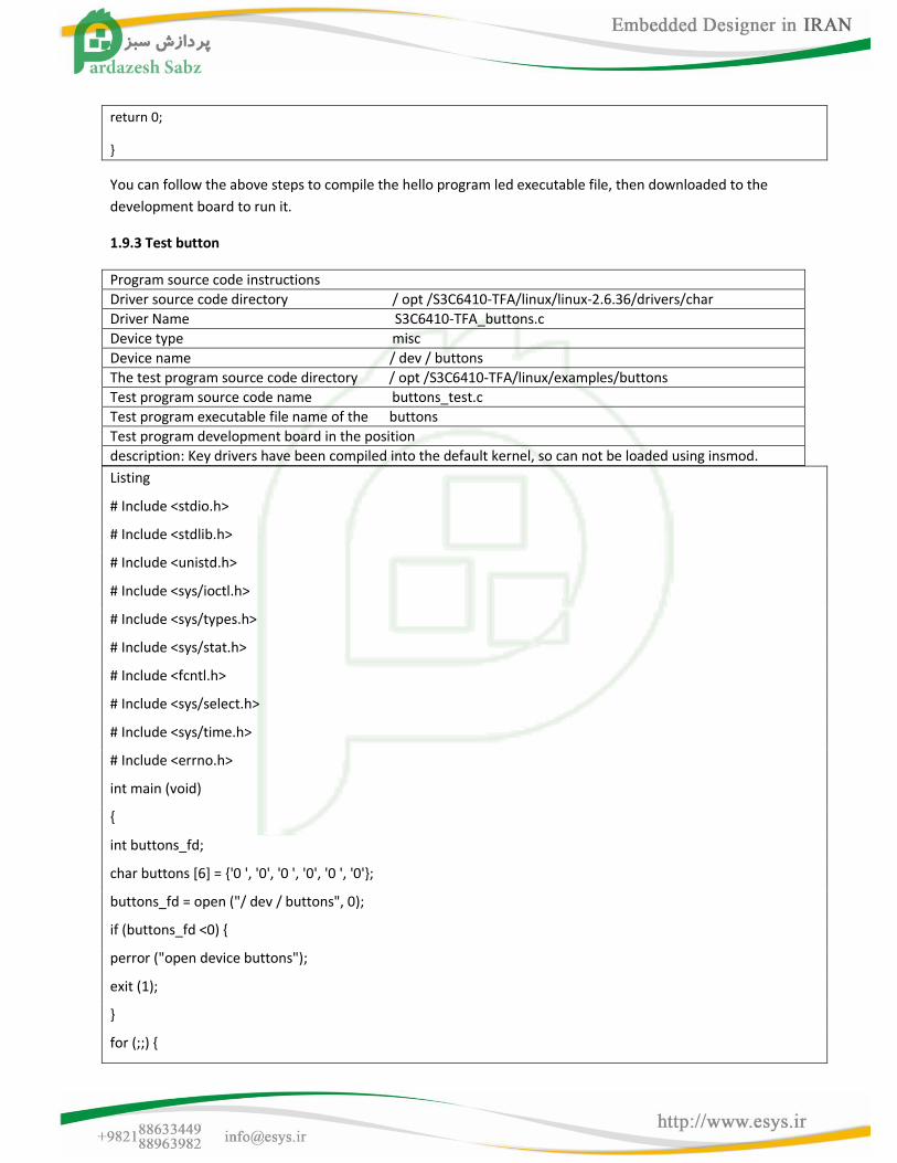
1.9.3 Test button
Program source code instructions
Driver source code directory / opt /S3C6410-TFA/linux/linux-2.6.36/drivers/char
Driver Name S3C6410-TFA_buttons.c
Device type misc
Device name / dev / buttons
The test program source code directory / opt /S3C6410-TFA/linux/examples/buttons
Test program source code name buttons_test.c
Test program executable file name of the buttons
Test program development board in the position
description: Key drivers have been compiled into the default kernel, so can not be loaded using insmod.
Listing
# Include <stdio.h>
# Include <stdlib.h>
# Include <unistd.h>
# Include <sys/ioctl.h>
# Include <sys/types.h>
# Include <sys/stat.h>
# Include <fcntl.h>
# Include <sys/select.h>
# Include <sys/time.h>
# Include <errno.h>
int main (void)
{
int buttons_fd;
char buttons [6] = {'0 ', '0', '0 ', '0', '0 ', '0'};
buttons_fd = open ("/ dev / buttons", 0);
if (buttons_fd <0) {
perror ("open device buttons");
exit (1);
}
for (;;) {
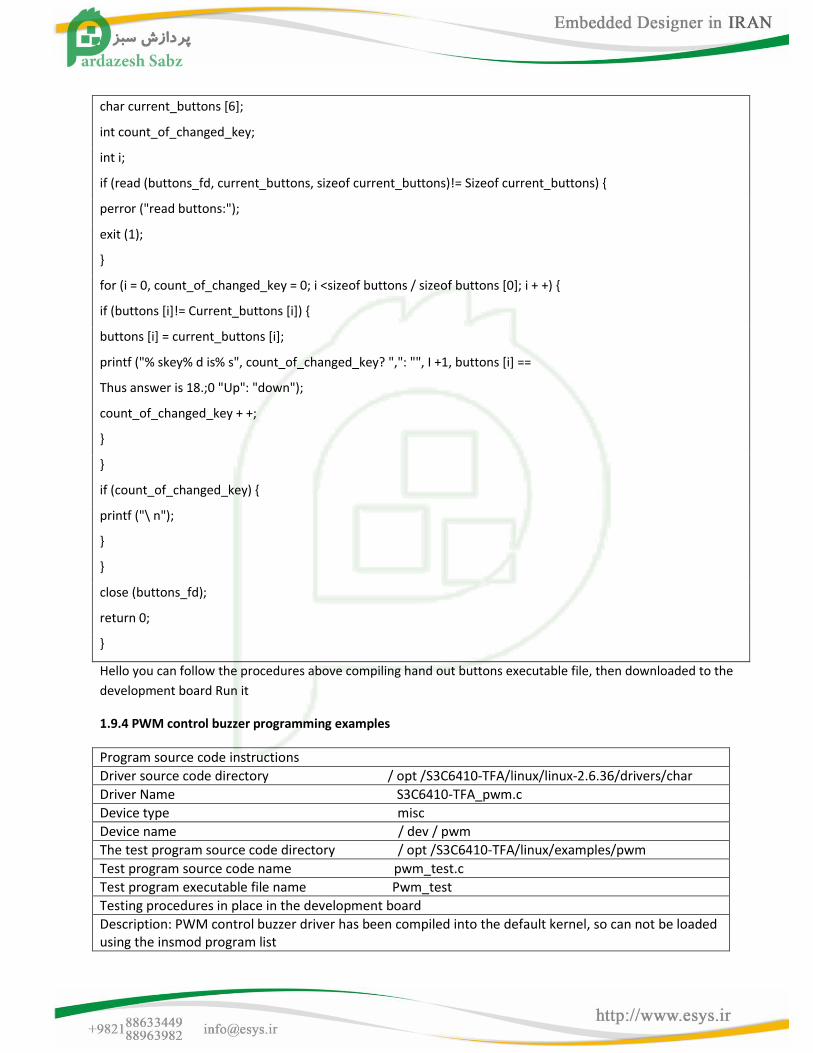
char current_buttons [6];
int count_of_changed_key;
int i;
if (read (buttons_fd, current_buttons, sizeof current_buttons)!= Sizeof current_buttons) {
perror ("read buttons:");
exit (1);
}
for (i = 0, count_of_changed_key = 0; i <sizeof buttons / sizeof buttons [0]; i + +) {
if (buttons [i]!= Current_buttons [i]) {
buttons [i] = current_buttons [i];
printf ("% skey% d is% s", count_of_changed_key? ",": "", I +1, buttons [i] ==
Thus answer is 18.;0 "Up": "down");
count_of_changed_key + +;
}
}
if (count_of_changed_key) {
printf ("\ n");
}
}
close (buttons_fd);
return 0;
}
Hello you can follow the procedures above compiling hand out buttons executable file, then downloaded to the
development board Run it
1.9.4 PWM control buzzer programming examples
Program source code instructions
Driver source code directory / opt /S3C6410-TFA/linux/linux-2.6.36/drivers/char
Driver Name S3C6410-TFA_pwm.c
Device type misc
Device name / dev / pwm
The test program source code directory / opt /S3C6410-TFA/linux/examples/pwm
Test program source code name pwm_test.c
Test program executable file name Pwm_test
Testing procedures in place in the development board
Description: PWM control buzzer driver has been compiled into the default kernel, so can not be loaded using the insmod program list
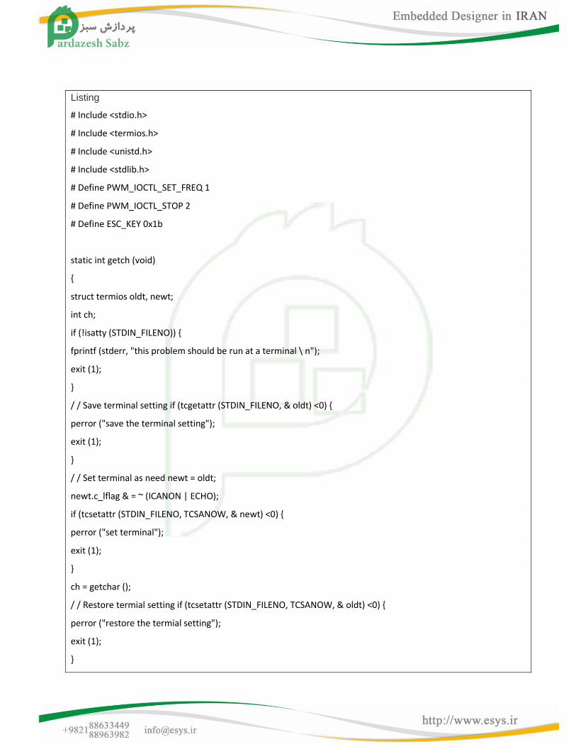
Listing
# Include <stdio.h>
# Include <termios.h>
# Include <unistd.h>
# Include <stdlib.h>
# Define PWM_IOCTL_SET_FREQ 1
# Define PWM_IOCTL_STOP 2
# Define ESC_KEY 0x1b
static int getch (void)
{
struct termios oldt, newt;
int ch;
if (!isatty (STDIN_FILENO)) {
fprintf (stderr, "this problem should be run at a terminal \ n");
exit (1);
}
/ / Save terminal setting if (tcgetattr (STDIN_FILENO, & oldt) <0) {
perror ("save the terminal setting");
exit (1);
}
/ / Set terminal as need newt = oldt;
newt.c_lflag & = ~ (ICANON | ECHO);
if (tcsetattr (STDIN_FILENO, TCSANOW, & newt) <0) {
perror ("set terminal");
exit (1);
}
ch = getchar ();
/ / Restore termial setting if (tcsetattr (STDIN_FILENO, TCSANOW, & oldt) <0) {
perror ("restore the termial setting");
exit (1);
}
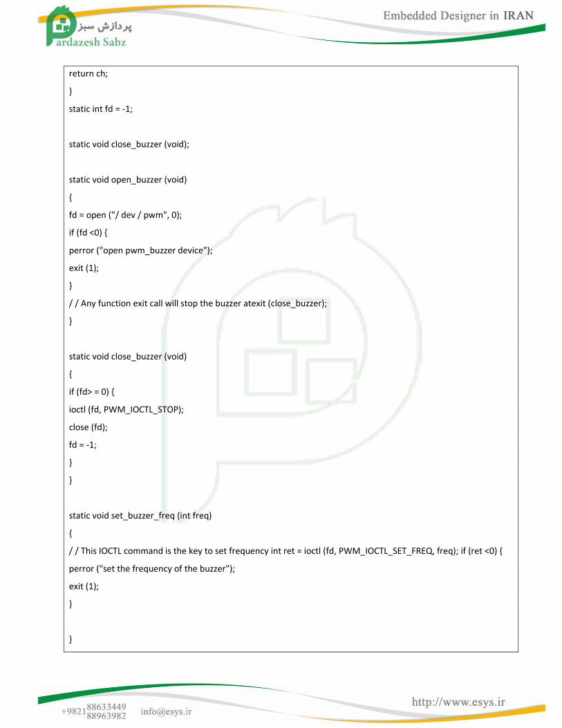
return ch;
}
static int fd = -1;
static void close_buzzer (void);
static void open_buzzer (void)
{
fd = open ("/ dev / pwm", 0);
if (fd <0) {
perror ("open pwm_buzzer device");
exit (1);
}
/ / Any function exit call will stop the buzzer atexit (close_buzzer);
}
static void close_buzzer (void)
{
if (fd> = 0) {
ioctl (fd, PWM_IOCTL_STOP);
close (fd);
fd = -1;
}
}
static void set_buzzer_freq (int freq)
{
/ / This IOCTL command is the key to set frequency int ret = ioctl (fd, PWM_IOCTL_SET_FREQ, freq); if (ret <0) {
perror ("set the frequency of the buzzer");
exit (1);
}
}
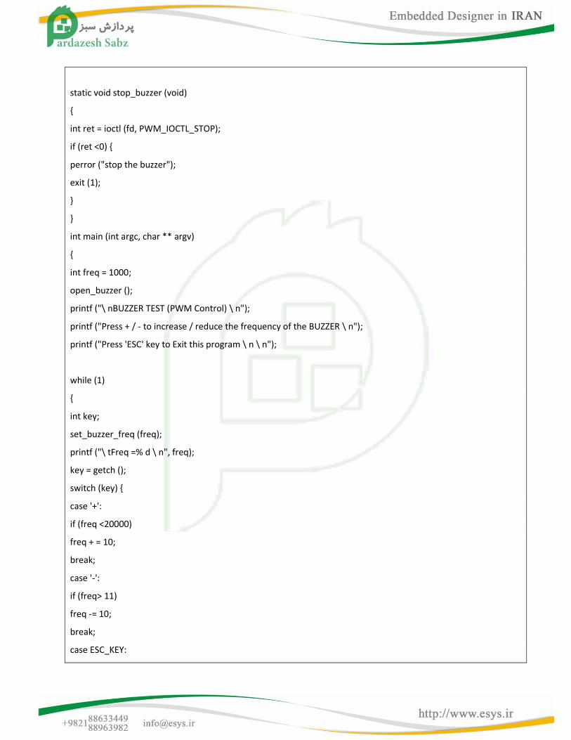
static void stop_buzzer (void)
{
int ret = ioctl (fd, PWM_IOCTL_STOP);
if (ret <0) {
perror ("stop the buzzer");
exit (1);
}
}
int main (int argc, char ** argv)
{
int freq = 1000;
open_buzzer ();
printf ("\ nBUZZER TEST (PWM Control) \ n");
printf ("Press + / - to increase / reduce the frequency of the BUZZER \ n");
printf ("Press 'ESC' key to Exit this program \ n \ n");
while (1)
{
int key;
set_buzzer_freq (freq);
printf ("\ tFreq =% d \ n", freq);
key = getch ();
switch (key) {
case '+':
if (freq <20000)
freq + = 10;
break;
case '-':
if (freq> 11)
freq -= 10;
break;
case ESC_KEY:
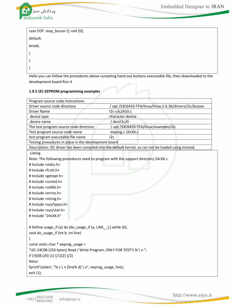
case EOF: stop_buzzer (); exit (0);
default:
break;
}
}
}
Hello you can follow the procedures above compiling hand out buttons executable file, then downloaded to the
development board Run it
1.9.5 I2C-EEPROM programming examples
Program source code instructions
Driver source code directory / opt /S3C6410-TFA/linux/linux-2.6.36/drivers/i2c/busses
Driver Name I2c-s3c2410.c
device type character device
device name / dev/i2c/0
The test program source code directory / opt /S3C6410-TFA/linux/examples/i2c
Test program source code name eeprog.c 24cXX.c
test program executable file name I2c
Testing procedures in place in the development board
Description: I2C driver has been compiled into the default kernel, so can not be loaded using insmod.
Listing
Note: The following procedures need to program with the support directory 24cXX.c
# Include <stdio.h>
# Include <fcntl.h>
# Include <getopt.h>
# Include <unistd.h>
# Include <stdlib.h>
# Include <errno.h>
# Include <string.h>
# Include <sys/types.h>
# Include <sys/stat.h>
# Include "24cXX.h"
# Define usage_if (a) do {do_usage_if (a, LINE__);} while (0);
void do_usage_if (int b, int line)
{
const static char * eeprog_usage =
"I2C-24C08 (256 bytes) Read / Write Program, ONLY FOR TEST!\ N \ n ";
if (!{0}B.{/0} {1} {/1}{2} {/2}
Retur
fprintf (stderr, "% s \ n [line% d] \ n", eeprog_usage, line);
exit (1);
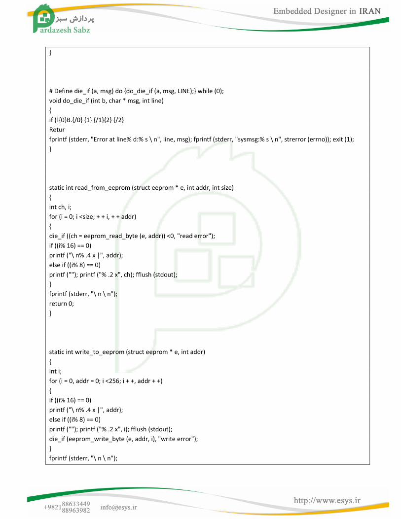
}
# Define die_if (a, msg) do {do_die_if (a, msg, LINE);} while (0);
void do_die_if (int b, char * msg, int line)
{
if (!{0}B.{/0} {1} {/1}{2} {/2}
Retur
fprintf (stderr, "Error at line% d:% s \ n", line, msg); fprintf (stderr, "sysmsg:% s \ n", strerror (errno)); exit (1);
}
static int read_from_eeprom (struct eeprom * e, int addr, int size)
{
int ch, i;
for (i = 0; i <size; + + i, + + addr)
{
die_if ((ch = eeprom_read_byte (e, addr)) <0, "read error");
if ((i% 16) == 0)
printf ("\ n% .4 x |", addr);
else if ((i% 8) == 0)
printf (""); printf ("% .2 x", ch); fflush (stdout);
}
fprintf (stderr, "\ n \ n");
return 0;
}
static int write_to_eeprom (struct eeprom * e, int addr)
{
int i;
for (i = 0, addr = 0; i <256; i + +, addr + +)
{
if ((i% 16) == 0)
printf ("\ n% .4 x |", addr);
else if ((i% 8) == 0)
printf (""); printf ("% .2 x", i); fflush (stdout);
die_if (eeprom_write_byte (e, addr, i), "write error");
}
fprintf (stderr, "\ n \ n");
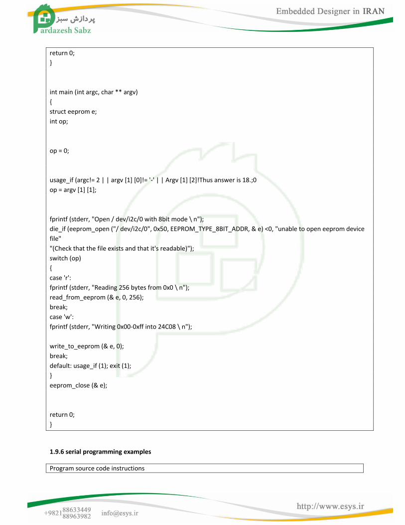
return 0;
}
int main (int argc, char ** argv)
{
struct eeprom e;
int op;
op = 0;
usage_if (argc!= 2 | | argv [1] [0]!= '-' | | Argv [1] [2]!Thus answer is 18.;0
op = argv [1] [1];
fprintf (stderr, "Open / dev/i2c/0 with 8bit mode \ n");
die_if (eeprom_open ("/ dev/i2c/0", 0x50, EEPROM_TYPE_8BIT_ADDR, & e) <0, "unable to open eeprom device
file"
"(Check that the file exists and that it's readable)");
switch (op)
{
case 'r':
fprintf (stderr, "Reading 256 bytes from 0x0 \ n");
read_from_eeprom (& e, 0, 256);
break;
case 'w':
fprintf (stderr, "Writing 0x00-0xff into 24C08 \ n");
write_to_eeprom (& e, 0);
break;
default: usage_if (1); exit (1);
}
eeprom_close (& e);
return 0;
}
1.9.6 serial programming examples
Program source code instructions
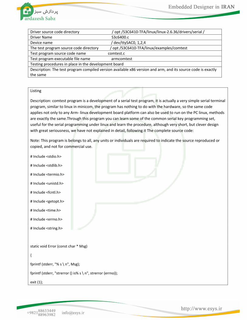
Driver source code directory / opt /S3C6410-TFA/linux/linux-2.6.36/drivers/serial /
Driver Name S3c6400.c
Device name / dev/ttySAC0, 1,2,4
The test program source code directory / opt /S3C6410-TFA/linux/examples/comtest
Test program source code name comtest.c
Test program executable file name armcomtest
Testing procedures in place in the development board
Description: The test program compiled version available x86 version and arm, and its source code is exactly the same
Listing
Description: comtest program is a development of a serial test program, it is actually a very simple serial terminal
program, similar to linux in minicom, the program has nothing to do with the hardware, so the same code
applies not only to any Arm- linux development board platform can also be used to run on the PC linux, methods
are exactly the same.Through this program you can learn some of the common serial key programming set,
useful for the serial programming under linux and learn the procedure, although very short, but clever design
with great seriousness, we have not explained in detail, following it The complete source code:
Note: This program is belongs to all, any units or individuals are required to indicate the source reproduced or
copied, and not for commercial use.
# Include <stdio.h>
# Include <stdlib.h>
# Include <termio.h>
# Include <unistd.h>
# Include <fcntl.h>
# Include <getopt.h>
# Include <time.h>
# Include <errno.h>
# Include <string.h>
static void Error (const char * Msg)
{
fprintf (stderr, "% s \ n", Msg);
fprintf (stderr, "strerror () is% s \ n", strerror (errno));
exit (1);
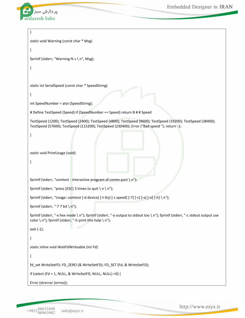
}
static void Warning (const char * Msg)
{
fprintf (stderr, "Warning:% s \ n", Msg);
}
static int SerialSpeed (const char * SpeedString)
{
int SpeedNumber = atoi (SpeedString);
# Define TestSpeed (Speed) if (SpeedNumber == Speed) return B # # Speed
TestSpeed (1200); TestSpeed (2400); TestSpeed (4800); TestSpeed (9600); TestSpeed (19200); TestSpeed (38400); TestSpeed (57600); TestSpeed (115200); TestSpeed (230400); Error ("Bad speed "); return -1;
}
static void PrintUsage (void)
{
fprintf (stderr, "comtest - interactive program of comm port \ n");
fprintf (stderr, "press [ESC] 3 times to quit \ n \ n");
fprintf (stderr, "Usage: comtest [-d device] [-t tty] [-s speed] [-7] [-c] [-x] [-o] [-h] \ n");
fprintf (stderr, "-7 7 bit \ n");
fprintf (stderr, "-x hex mode \ n"); fprintf (stderr, "-o output to stdout too \ n"); fprintf (stderr, "-c stdout output use color \ n"); fprintf (stderr, "-h print this help \ n");
exit (-1);
}
static inline void WaitFdWriteable (int Fd)
{
fd_set WriteSetFD; FD_ZERO (& WriteSetFD); FD_SET (Fd, & WriteSetFD);
if (select (Fd + 1, NULL, & WriteSetFD, NULL, NULL) <0) {
Error (strerror (errno));
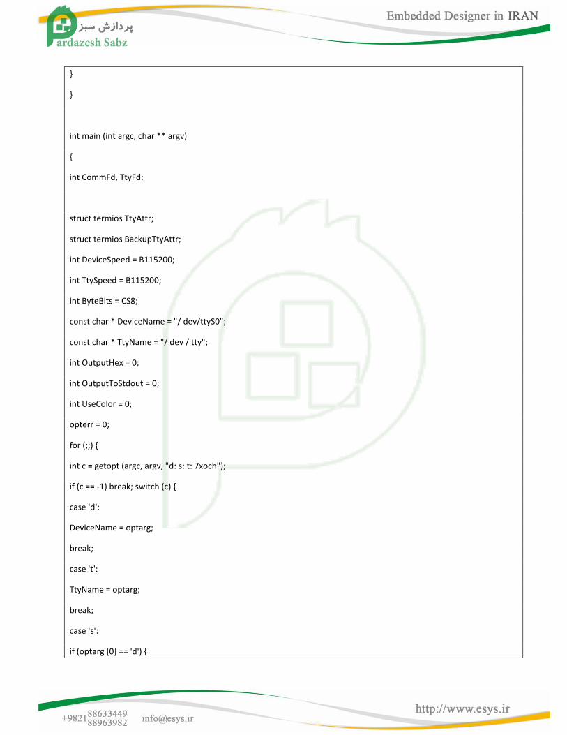
}
}
int main (int argc, char ** argv)
{
int CommFd, TtyFd;
struct termios TtyAttr;
struct termios BackupTtyAttr;
int DeviceSpeed = B115200;
int TtySpeed = B115200;
int ByteBits = CS8;
const char * DeviceName = "/ dev/ttyS0";
const char * TtyName = "/ dev / tty";
int OutputHex = 0;
int OutputToStdout = 0;
int UseColor = 0;
opterr = 0;
for (;;) {
int c = getopt (argc, argv, "d: s: t: 7xoch");
if (c == -1) break; switch (c) {
case 'd':
DeviceName = optarg;
break;
case 't':
TtyName = optarg;
break;
case 's':
if (optarg [0] == 'd') {
DeviceSpeed = SerialSpeed (optarg + 1);
} Else if (optarg [0] == 't') {
TtySpeed = SerialSpeed (optarg + 1);
} Else
case 'o':
TtySpeed = DeviceSpeed = SerialSpeed (optarg);
break;
OutputToStdout = 1;
break;
case '7 ':
ByteBits = CS7;
break;
case 'x':
OutputHex = 1;
break;
case 'c':
UseColor = 1;
break; case '?': case 'h': default:
PrintUsage ();
}
}
if (optind!= Argc) PrintUsage ();
CommFd = open (DeviceName, O_RDWR, 0);
if (CommFd <0)
Error ("Unable to open device");
if (fcntl (CommFd, F_SETFL, O_NONBLOCK) <0) Error ("Unable set to NONBLOCK mode");
memset (& TtyAttr, 0, sizeof (struct termios)); TtyAttr.c_iflag = IGNPAR;
TtyAttr.c_cflag = DeviceSpeed | HUPCL | ByteBits | CREAD | CLOCAL;
TtyAttr.c_cc [VMIN] = 1;
if (tcsetattr (CommFd, TCSANOW, & TtyAttr) <0) Warning ("Unable to set comm port");
TtyFd = open (TtyName, O_RDWR | O_NDELAY, 0);
if (TtyFd <0) Error ("Unable to open tty");
TtyAttr.c_cflag = TtySpeed | HUPCL | ByteBits | CREAD | CLOCAL;
if (tcgetattr (TtyFd, & BackupTtyAttr) <0) Error ("Unable to get tty");
if (tcsetattr (TtyFd, TCSANOW, & TtyAttr) <0) Error ("Unable to set tty");
for (;;) {
unsigned char Char = 0;
fd_set ReadSetFD;
void OutputStdChar (FILE * File) {
char Buffer [10];
int Len = sprintf (Buffer, OutputHex? "% .2 X": "% c", Char);
fwrite (Buffer, 1, Len, File);
}
FD_ZERO (& ReadSetFD);
FD_SET (CommFd, & ReadSetFD); FD_SET (TtyFd, & ReadSetFD);
# Define max (x, y) (((x)> = (y))? (X): (y))
if (select (max (CommFd, TtyFd) + 1, & ReadSetFD, NULL, NULL, NULL) <0) {Error (strerror (errno));
}
# Undef max
if (FD_ISSET (CommFd, & ReadSetFD)) {
while (read (CommFd, & Char, 1) == 1) {
WaitFdWriteable (TtyFd);
if (write (TtyFd, & Char, 1) <0) {Error (strerror (errno));
}
if (OutputToStdout) {
if (UseColor) fwrite ("\ x1b [01; 34m", 1, 8, stdout); OutputStdChar (stdout);
if (UseColor)
fwrite ("\ x1b [00m", 1, 8, stdout);
fflush (stdout);
}
}
}
if (FD_ISSET (TtyFd, & ReadSetFD)) {
while (read (TtyFd, & Char, 1) == 1) {
static int EscKeyCount = 0; WaitFdWriteable (CommFd);
if (write (CommFd, & Char, 1) <0) {
Error (strerror (errno));
}
if (OutputToStdout) {if (UseColor) fwrite ("\ x1b [01; 31m", 1, 8, stderr); OutputStdChar (stderr);
if (UseColor) fwrite ("\ x1b [00m", 1, 8, stderr); fflush (stderr);
}
if (Char == '\ x1b') {EscKeyCount + +;
if (EscKeyCount> = 3)
} Else
goto ExitLabel;
EscKeyCount = 0;
}
}
}
ExitLabel:
if (tcsetattr (TtyFd, TCSANOW, & BackupTtyAttr) <0) Error ("Unable to set tty");
return 0;
}
1.9.7 UDP network programming
Program source code instructions

Driver source code directory / opt /S3C6410-TFA/linux/linux-2.6.36/drivers/net /
Driver Name dm9000.c
Major number of the drive without
Device name eth0 (network equipment is not in the / dev directory there)
The test program source code directory / opt /S3C6410-TFA/linux/examples/udptak
Test program source code name udptalk.c
Test program executable file name udptalk.c
Description: The test program compiled version available x86 version and arm, and its source code is exactly the same
Principle of the program
TCP / IP provides a connectionless transport layer protocol: UDP (User Datagram Protocol, that is, User Datagram
Protocol).UDP and TCP are very different, because there was no connection and connection-oriented socket
programming socket programming, there are big differences.Since no connection is established, each sending a
received datagram contains the sender and the recipient's address information.
Sending and receiving data, have to create a datagram socket means, the socket is of type SOCK_DGRAM, use
the following call produces:
sockfd = socket (AF_INET, SOCK_DGRAM, 0);
Since no connection is established, resulting in direct socket after sending and receiving of.Of course, to receive
the data reported must also be bound to a port, or the sender can not know which port to send to.Sendto and
recvfrom two system calls are used to send and receive datagrams, the call format:
int sendto (int s, const void * msg, int len, unsigned int flags, const struct sockaddr * to, int tolen);
int recvfrom (int, s, void * buf, int len, unsigned int flags, struct sockaddr * from, int fromlen);
Where s is used by the socket, msg and buf respectively send and receive buffer pointer, len is the length of the
buffer, flags For the option flag, here is also less than, is set to 0.is sent to and from the destination address and
receive the source address, contains the IP address and port information.tolen and fromlen are both to and from
the length of socket address structure.These two functions return value is the actual number of bytes sent and
received, or -1 for an error.
No connection with the basic communication process as shown.
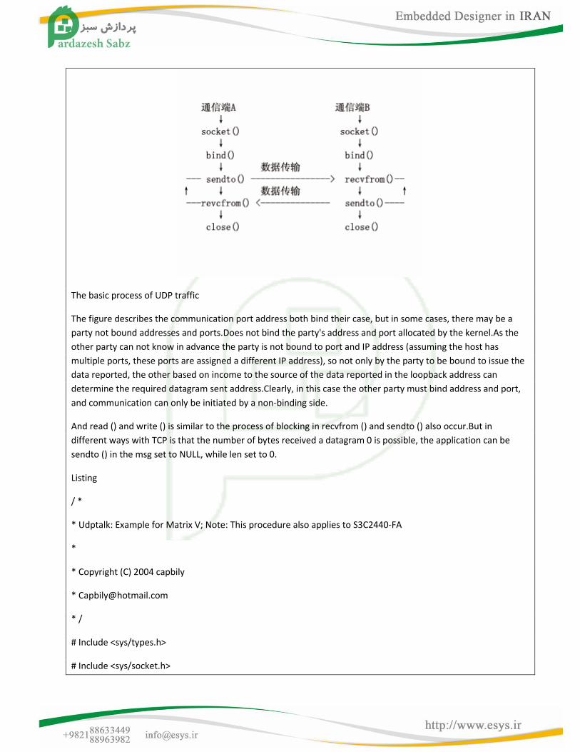
The basic process of UDP traffic
The figure describes the communication port address both bind their case, but in some cases, there may be a
party not bound addresses and ports.Does not bind the party's address and port allocated by the kernel.As the
other party can not know in advance the party is not bound to port and IP address (assuming the host has
multiple ports, these ports are assigned a different IP address), so not only by the party to be bound to issue the
data reported, the other based on income to the source of the data reported in the loopback address can
determine the required datagram sent address.Clearly, in this case the other party must bind address and port,
and communication can only be initiated by a non-binding side.
And read () and write () is similar to the process of blocking in recvfrom () and sendto () also occur.But in
different ways with TCP is that the number of bytes received a datagram 0 is possible, the application can be
sendto () in the msg set to NULL, while len set to 0.
Listing
/ *
* Udptalk: Example for Matrix V; Note: This procedure also applies to S3C2440-FA
*
* Copyright (C) 2004 capbily
* /
# Include <sys/types.h>
# Include <sys/socket.h>
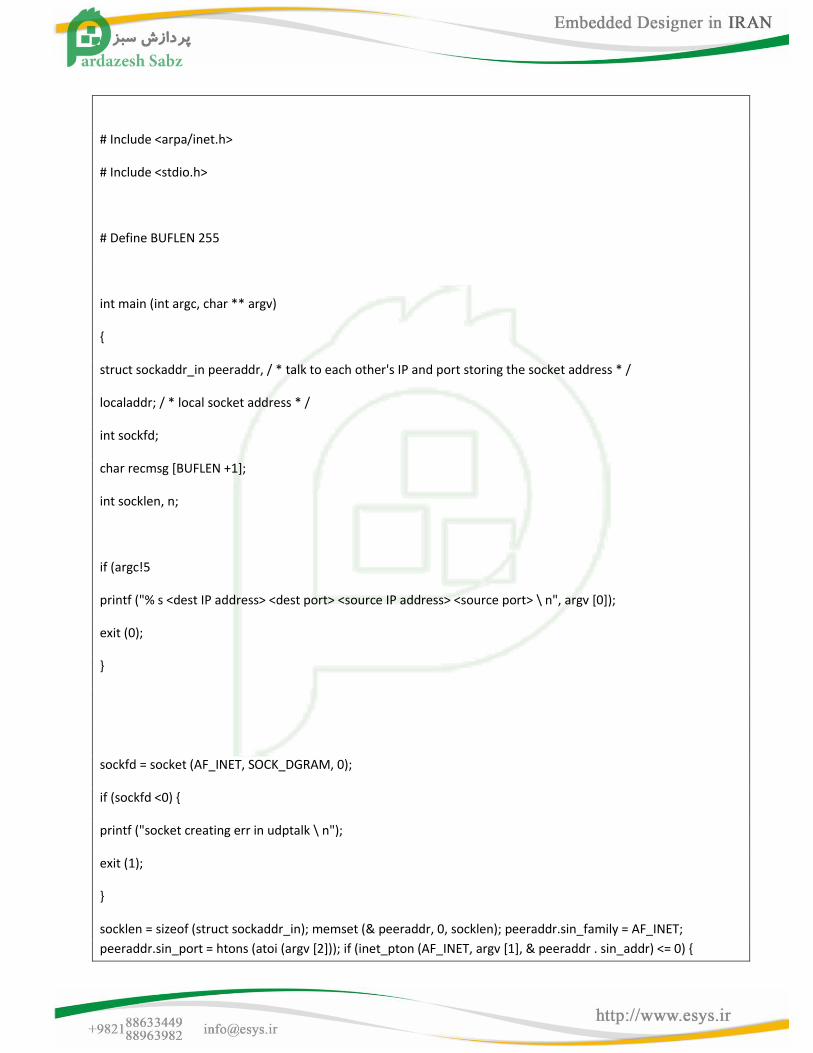
# Include <arpa/inet.h>
# Include <stdio.h>
# Define BUFLEN 255
int main (int argc, char ** argv)
{
struct sockaddr_in peeraddr, / * talk to each other's IP and port storing the socket address * /
localaddr; / * local socket address * /
int sockfd;
char recmsg [BUFLEN +1];
int socklen, n;
if (argc!5
printf ("% s <dest IP address> <dest port> <source IP address> <source port> \ n", argv [0]);
exit (0);
}
sockfd = socket (AF_INET, SOCK_DGRAM, 0);
if (sockfd <0) {
printf ("socket creating err in udptalk \ n");
exit (1);
}
socklen = sizeof (struct sockaddr_in); memset (& peeraddr, 0, socklen); peeraddr.sin_family = AF_INET;
peeraddr.sin_port = htons (atoi (argv [2])); if (inet_pton (AF_INET, argv [1], & peeraddr . sin_addr) <= 0) {
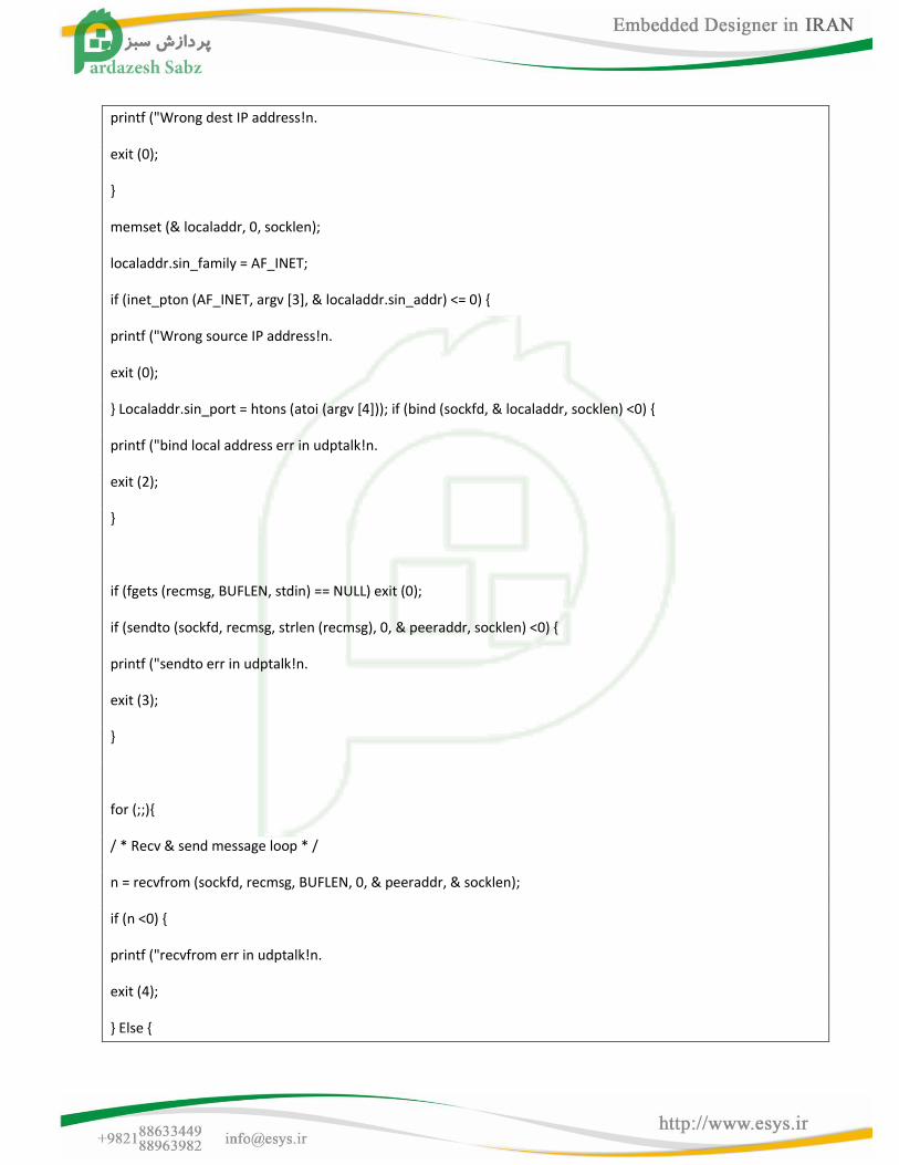
printf ("Wrong dest IP address!n.
exit (0);
}
memset (& localaddr, 0, socklen);
localaddr.sin_family = AF_INET;
if (inet_pton (AF_INET, argv [3], & localaddr.sin_addr) <= 0) {
printf ("Wrong source IP address!n.
exit (0);
} Localaddr.sin_port = htons (atoi (argv [4])); if (bind (sockfd, & localaddr, socklen) <0) {
printf ("bind local address err in udptalk!n.
exit (2);
}
if (fgets (recmsg, BUFLEN, stdin) == NULL) exit (0);
if (sendto (sockfd, recmsg, strlen (recmsg), 0, & peeraddr, socklen) <0) {
printf ("sendto err in udptalk!n.
exit (3);
}
for (;;){
/ * Recv & send message loop * /
n = recvfrom (sockfd, recmsg, BUFLEN, 0, & peeraddr, & socklen);
if (n <0) {
printf ("recvfrom err in udptalk!n.
exit (4);
} Else {
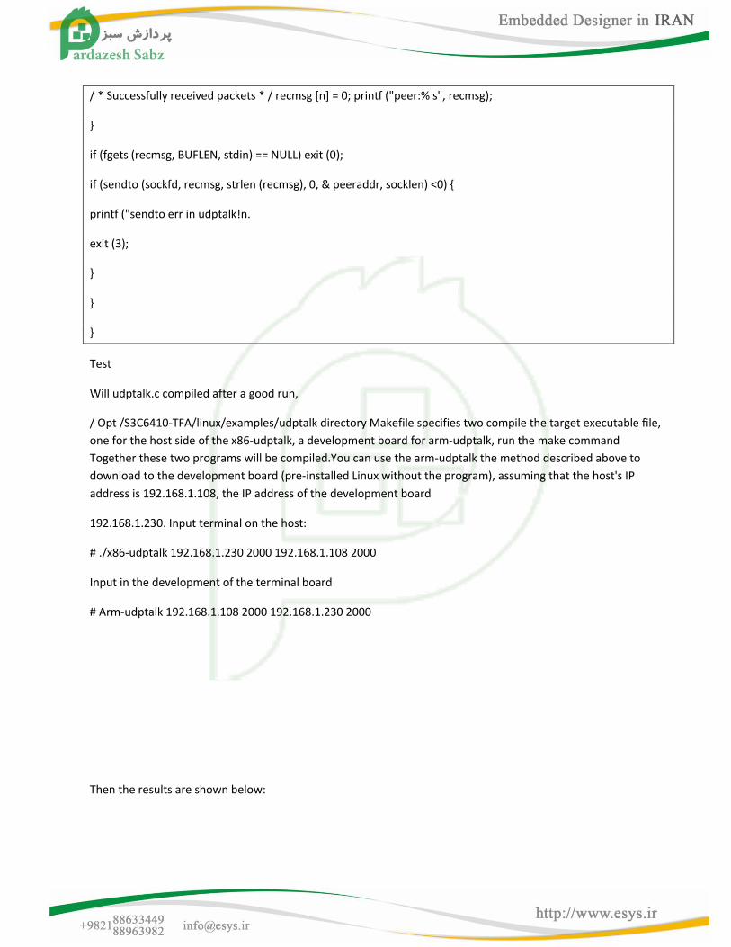
/ * Successfully received packets * / recmsg [n] = 0; printf ("peer:% s", recmsg);
}
if (fgets (recmsg, BUFLEN, stdin) == NULL) exit (0);
if (sendto (sockfd, recmsg, strlen (recmsg), 0, & peeraddr, socklen) <0) {
printf ("sendto err in udptalk!n.
exit (3);
}
}
}
Test
Will udptalk.c compiled after a good run,
/ Opt /S3C6410-TFA/linux/examples/udptalk directory Makefile specifies two compile the target executable file,
one for the host side of the x86-udptalk, a development board for arm-udptalk, run the make command
Together these two programs will be compiled.You can use the arm-udptalk the method described above to
download to the development board (pre-installed Linux without the program), assuming that the host's IP
address is 192.168.1.108, the IP address of the development board
192.168.1.230. Input terminal on the host:
# ./x86-udptalk 192.168.1.230 2000 192.168.1.108 2000
Input in the development of the terminal board
# Arm-udptalk 192.168.1.108 2000 192.168.1.230 2000
Then the results are shown below:
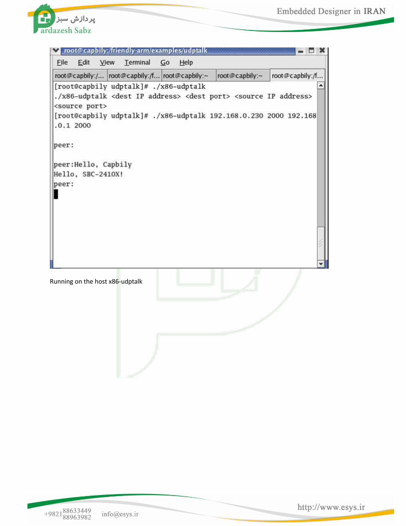
Running on the host x86-udptalk
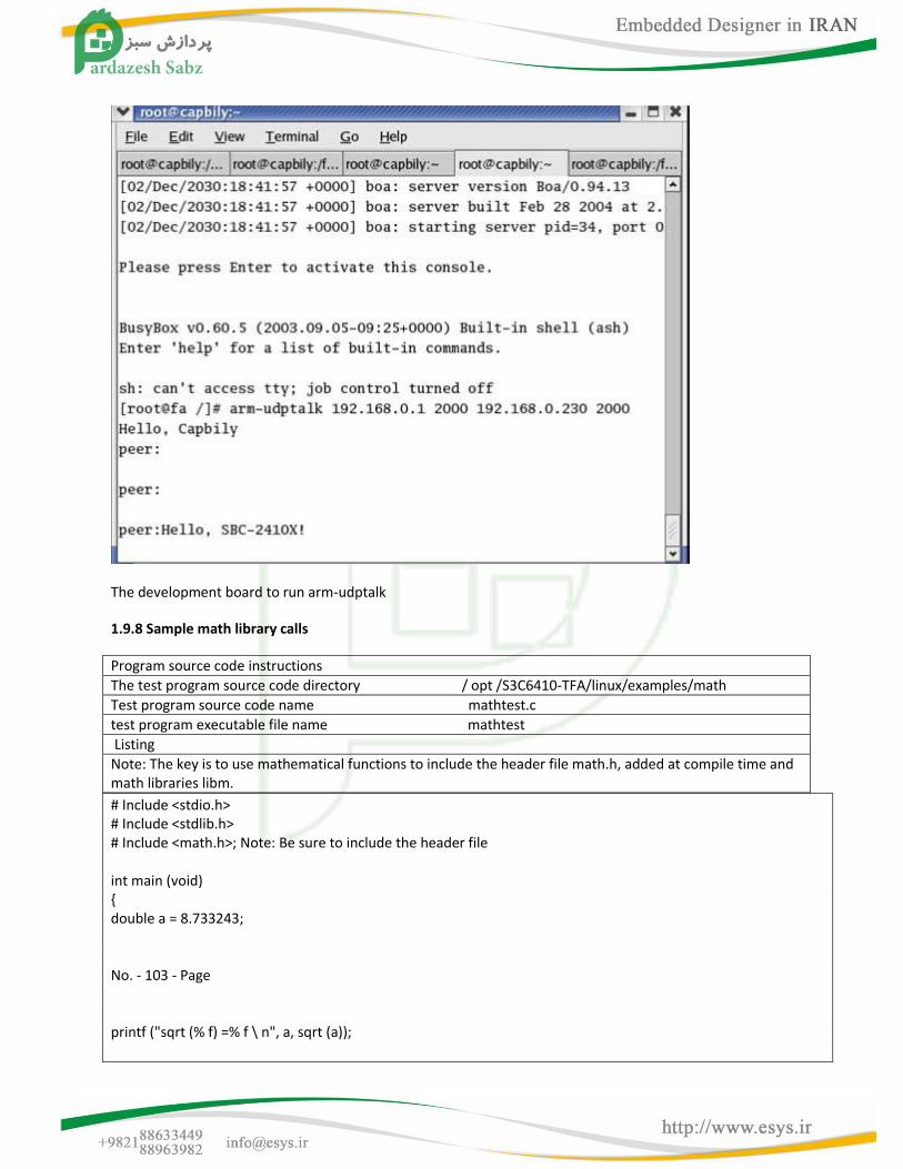
The development board to run arm-udptalk
1.9.8 Sample math library calls
Program source code instructions
The test program source code directory / opt /S3C6410-TFA/linux/examples/math
Test program source code name mathtest.c
test program executable file name mathtest
Listing
Note: The key is to use mathematical functions to include the header file math.h, added at compile time and math libraries libm.
# Include <stdio.h> # Include <stdlib.h> # Include <math.h>; Note: Be sure to include the header file int main (void) { double a = 8.733243; No. - 103 - Page printf ("sqrt (% f) =% f \ n", a, sqrt (a));
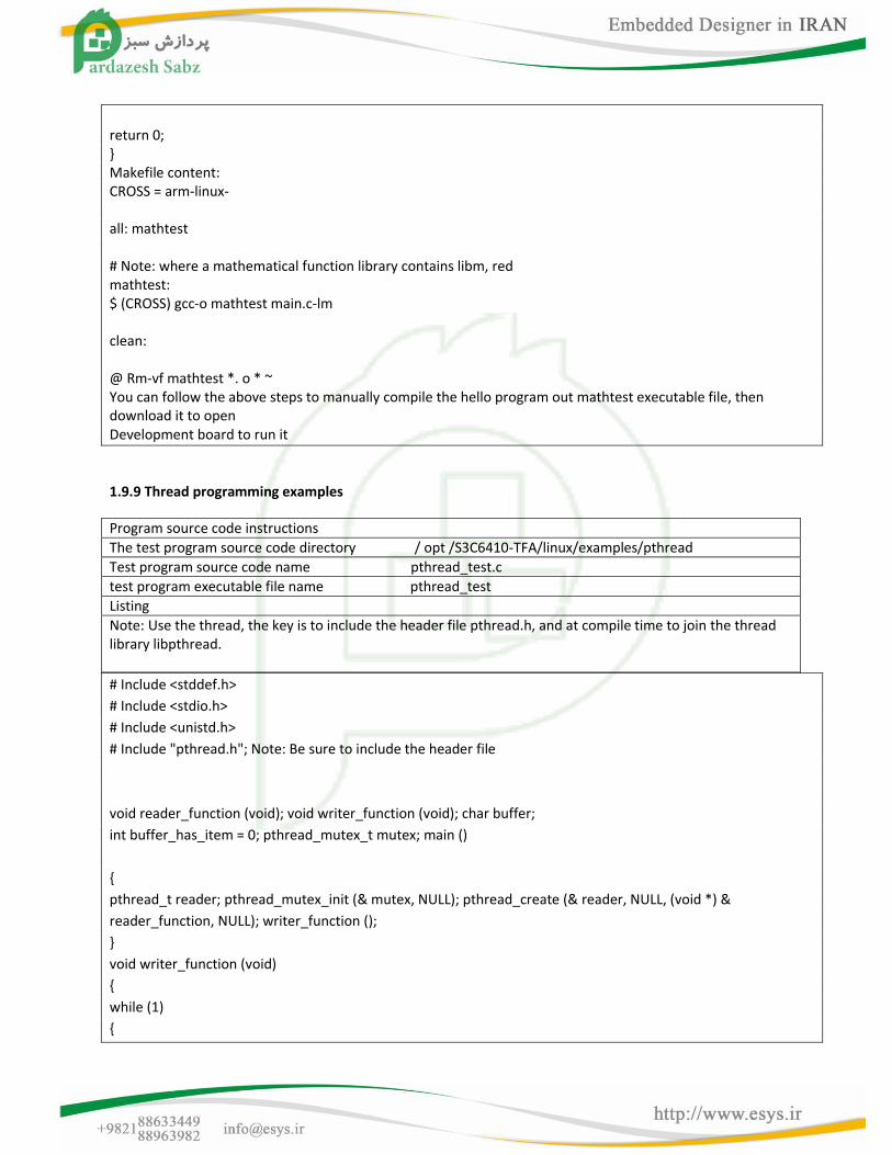
return 0; } Makefile content: CROSS = arm-linux- all: mathtest # Note: where a mathematical function library contains libm, red mathtest: $ (CROSS) gcc-o mathtest main.c-lm clean: @ Rm-vf mathtest *. o * ~ You can follow the above steps to manually compile the hello program out mathtest executable file, then download it to open Development board to run it
1.9.9 Thread programming examples
Program source code instructions
The test program source code directory / opt /S3C6410-TFA/linux/examples/pthread
Test program source code name pthread_test.c
test program executable file name pthread_test
Listing
Note: Use the thread, the key is to include the header file pthread.h, and at compile time to join the thread library libpthread.
# Include <stddef.h>
# Include <stdio.h>
# Include <unistd.h>
# Include "pthread.h"; Note: Be sure to include the header file
void reader_function (void); void writer_function (void); char buffer;
int buffer_has_item = 0; pthread_mutex_t mutex; main ()
{
pthread_t reader; pthread_mutex_init (& mutex, NULL); pthread_create (& reader, NULL, (void *) &
reader_function, NULL); writer_function ();
}
void writer_function (void)
{
while (1)
{
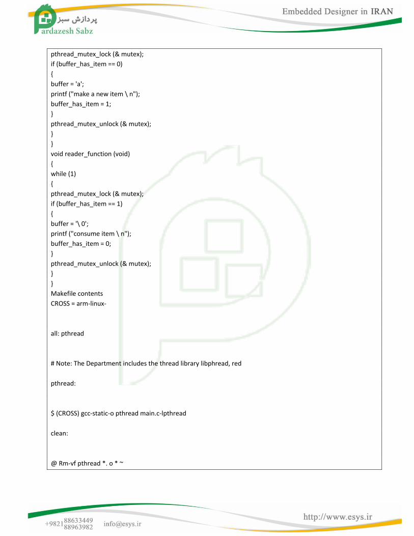
pthread_mutex_lock (& mutex);
if (buffer_has_item == 0)
{
buffer = 'a';
printf ("make a new item \ n");
buffer_has_item = 1;
}
pthread_mutex_unlock (& mutex);
}
}
void reader_function (void)
{
while (1)
{
pthread_mutex_lock (& mutex);
if (buffer_has_item == 1)
{
buffer = '\ 0';
printf ("consume item \ n");
buffer_has_item = 0;
}
pthread_mutex_unlock (& mutex);
}
}
Makefile contents
CROSS = arm-linux-
all: pthread
# Note: The Department includes the thread library libphread, red
pthread:
$ (CROSS) gcc-static-o pthread main.c-lpthread
clean:
@ Rm-vf pthread *. o * ~
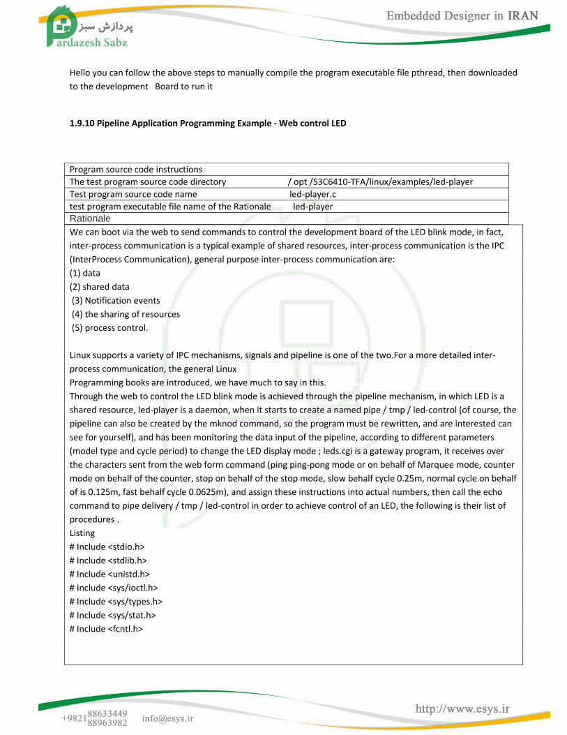
Hello you can follow the above steps to manually compile the program executable file pthread, then downloaded
to the development Board to run it
1.9.10 Pipeline Application Programming Example - Web control LED
Program source code instructions
The test program source code directory / opt /S3C6410-TFA/linux/examples/led-player
Test program source code name led-player.c
test program executable file name of the Rationale led-player Rationale
We can boot via the web to send commands to control the development board of the LED blink mode, in fact,
inter-process communication is a typical example of shared resources, inter-process communication is the IPC
(InterProcess Communication), general purpose inter-process communication are:
(1) data
(2) shared data
(3) Notification events
(4) the sharing of resources
(5) process control.
Linux supports a variety of IPC mechanisms, signals and pipeline is one of the two.For a more detailed inter-
process communication, the general Linux
Programming books are introduced, we have much to say in this.
Through the web to control the LED blink mode is achieved through the pipeline mechanism, in which LED is a
shared resource, led-player is a daemon, when it starts to create a named pipe / tmp / led-control (of course, the
pipeline can also be created by the mknod command, so the program must be rewritten, and are interested can
see for yourself), and has been monitoring the data input of the pipeline, according to different parameters
(model type and cycle period) to change the LED display mode ; leds.cgi is a gateway program, it receives over
the characters sent from the web form command (ping ping-pong mode or on behalf of Marquee mode, counter
mode on behalf of the counter, stop on behalf of the stop mode, slow behalf cycle 0.25m, normal cycle on behalf
of is 0.125m, fast behalf cycle 0.0625m), and assign these instructions into actual numbers, then call the echo
command to pipe delivery / tmp / led-control in order to achieve control of an LED, the following is their list of
procedures .
Listing
# Include <stdio.h>
# Include <stdlib.h>
# Include <unistd.h>
# Include <sys/ioctl.h>
# Include <sys/types.h>
# Include <sys/stat.h>
# Include <fcntl.h>
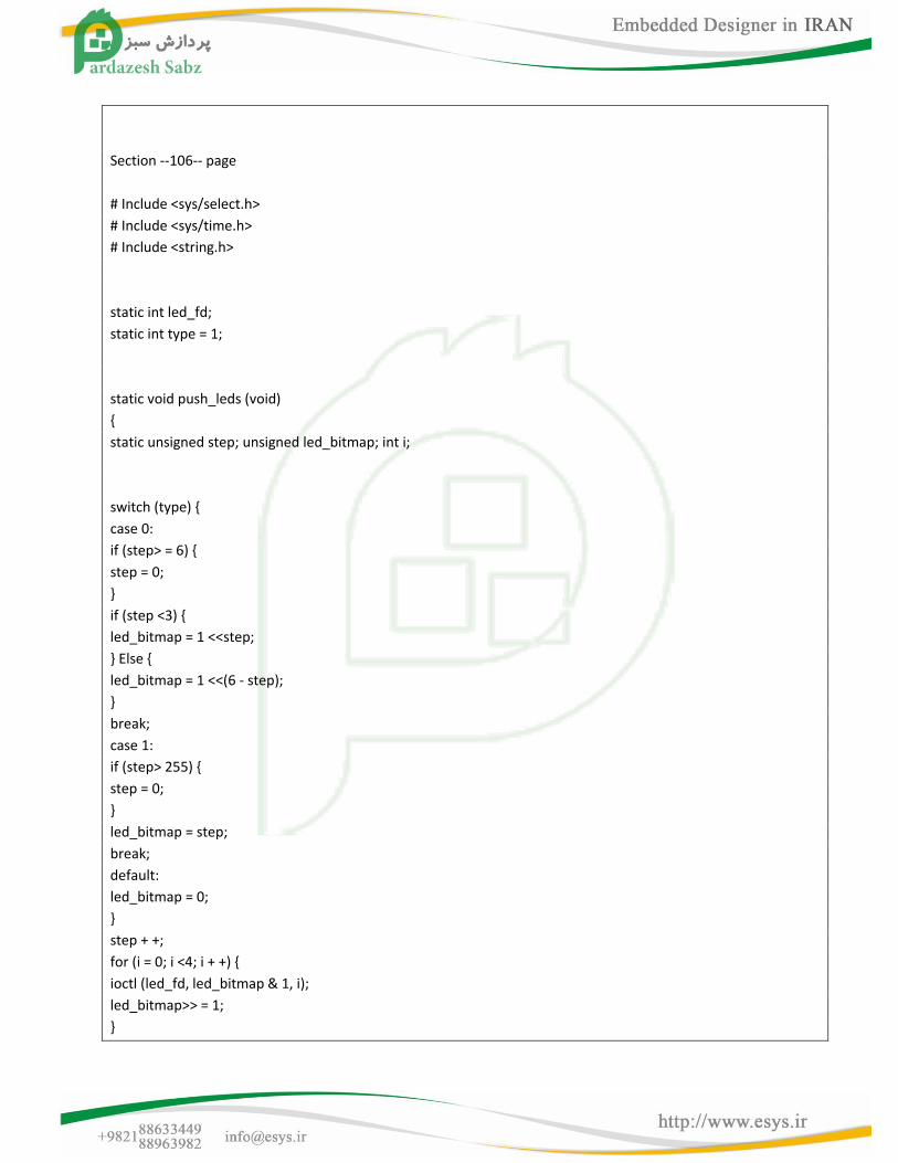
Section --106-- page
# Include <sys/select.h>
# Include <sys/time.h>
# Include <string.h>
static int led_fd;
static int type = 1;
static void push_leds (void)
{
static unsigned step; unsigned led_bitmap; int i;
switch (type) {
case 0:
if (step> = 6) {
step = 0;
}
if (step <3) {
led_bitmap = 1 <<step;
} Else {
led_bitmap = 1 <<(6 - step);
}
break;
case 1:
if (step> 255) {
step = 0;
}
led_bitmap = step;
break;
default:
led_bitmap = 0;
}
step + +;
for (i = 0; i <4; i + +) {
ioctl (led_fd, led_bitmap & 1, i);
led_bitmap>> = 1;
}
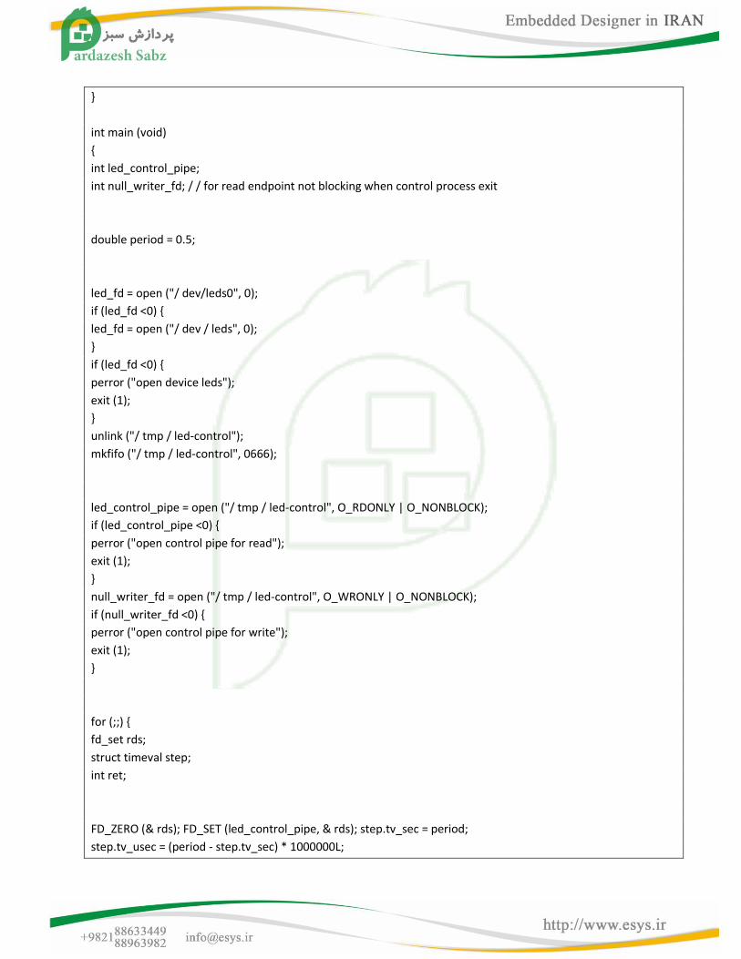
}
int main (void)
{
int led_control_pipe;
int null_writer_fd; / / for read endpoint not blocking when control process exit
double period = 0.5;
led_fd = open ("/ dev/leds0", 0);
if (led_fd <0) {
led_fd = open ("/ dev / leds", 0);
}
if (led_fd <0) {
perror ("open device leds");
exit (1);
}
unlink ("/ tmp / led-control");
mkfifo ("/ tmp / led-control", 0666);
led_control_pipe = open ("/ tmp / led-control", O_RDONLY | O_NONBLOCK);
if (led_control_pipe <0) {
perror ("open control pipe for read");
exit (1);
}
null_writer_fd = open ("/ tmp / led-control", O_WRONLY | O_NONBLOCK);
if (null_writer_fd <0) {
perror ("open control pipe for write");
exit (1);
}
for (;;) {
fd_set rds;
struct timeval step;
int ret;
FD_ZERO (& rds); FD_SET (led_control_pipe, & rds); step.tv_sec = period;
step.tv_usec = (period - step.tv_sec) * 1000000L;
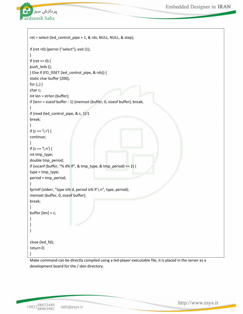
ret = select (led_control_pipe + 1, & rds, NULL, NULL, & step);
if (ret <0) {perror ("select"); exit (1);
}
if (ret == 0) {
push_leds ();
} Else if (FD_ISSET (led_control_pipe, & rds)) {
static char buffer [200];
for (;;) {
char c;
int len = strlen (buffer);
if (len> = sizeof buffer - 1) {memset (buffer, 0, sizeof buffer); break;
}
if (read (led_control_pipe, & c, 1)!1
break;
}
if (c == '\ r') {
continue;
}
if (c == '\ n') {
int tmp_type;
double tmp_period;
if (sscanf (buffer, "% d% lf", & tmp_type, & tmp_period) == 2) {
type = tmp_type;
period = tmp_period;
}
fprintf (stderr, "type is% d, period is% lf \ n", type, period);
memset (buffer, 0, sizeof buffer);
break;
}
buffer [len] = c;
}
}
}
close (led_fd);
return 0;
}
Make command can be directly compiled using a led-player executable file, it is placed in the server as a
development board for the / sbin directory.
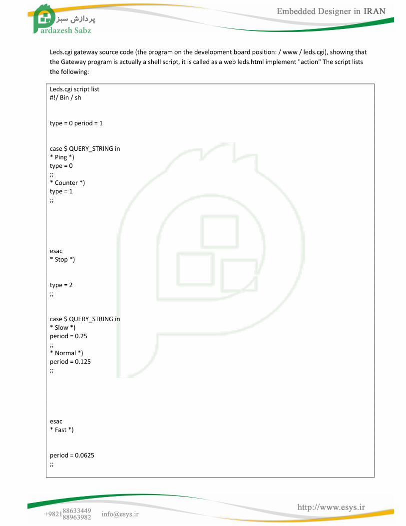
Leds.cgi gateway source code (the program on the development board position: / www / leds.cgi), showing that
the Gateway program is actually a shell script, it is called as a web leds.html implement "action" The script lists
the following:
Leds.cgi script list #!/ Bin / sh type = 0 period = 1 case $ QUERY_STRING in * Ping *) type = 0 ;; * Counter *) type = 1 ;; esac * Stop *) type = 2 ;; case $ QUERY_STRING in * Slow *) period = 0.25 ;; * Normal *) period = 0.125 ;; esac * Fast *) period = 0.0625 ;;
/ Bin / echo $ type $ period> / tmp / led-control echo "Content-type: text / html; charset = gb2312" echo / Bin / cat led-result.template exit 0
1.9.11 Based on the C + + Hello, World
Program source code instructions
The test program source code directory / opt /S3C6410-TFA/linux/examples/c + +
Test program source code name cplus.c + +
test program executable file name cplus
Listing
# Include <iostream> # Include <cstring> using namespace std; class String { private: public: char * str; String (char * s) { int lenght = strlen (s); str = new char [lenght +1]; strcpy (str, s); } ~ String () { cout <<"Deleting str. \ n"; delete [] str; } void display () { cout <<str <<endl; } };
int main (void) { Section --111-- page String s1 = "Hello world"; cout <<"s1 ="; s1.display (); return 0; double num, ans; cout <<"Enter num:"; }
Run it You can follow the above steps to manually compile the hello program out cplus executable file, then
downloaded to the development board
1.10 Examples of embedded Linux drivers
The previous section we introduced a simple Linux program Hello, World, which is run in user mode applications,
and now we start with a run in kernel mode Hello, World program began, the driver described the preparation
and use.
1.10.1 Hello, Module-simple embedded Linux driver module
Program source code instructions
Source code directory / opt /S3C6410-TFA/linux/linux-2.6.36/drivers/char
Source code file name S3C6410-TFA_hello_module.c
Major number of the drive without
Device name No
The test program source code directory No
Name of test procedures No
Test program executable file name No
Description: The driver will not load any of the dev device nodes to create
Listing
# Include <linux/kernel.h>
# Include <linux/module.h>
static int init S3C6410-TFA_hello_module_init (void)
{
printk ("Hello, S3C6410-TFA module is installed!n.
return 0;
}
static void exit S3C6410-TFA_hello_module_cleanup (void)
{
printk ("Good-bye, S3C6410-TFA module was removed!n.
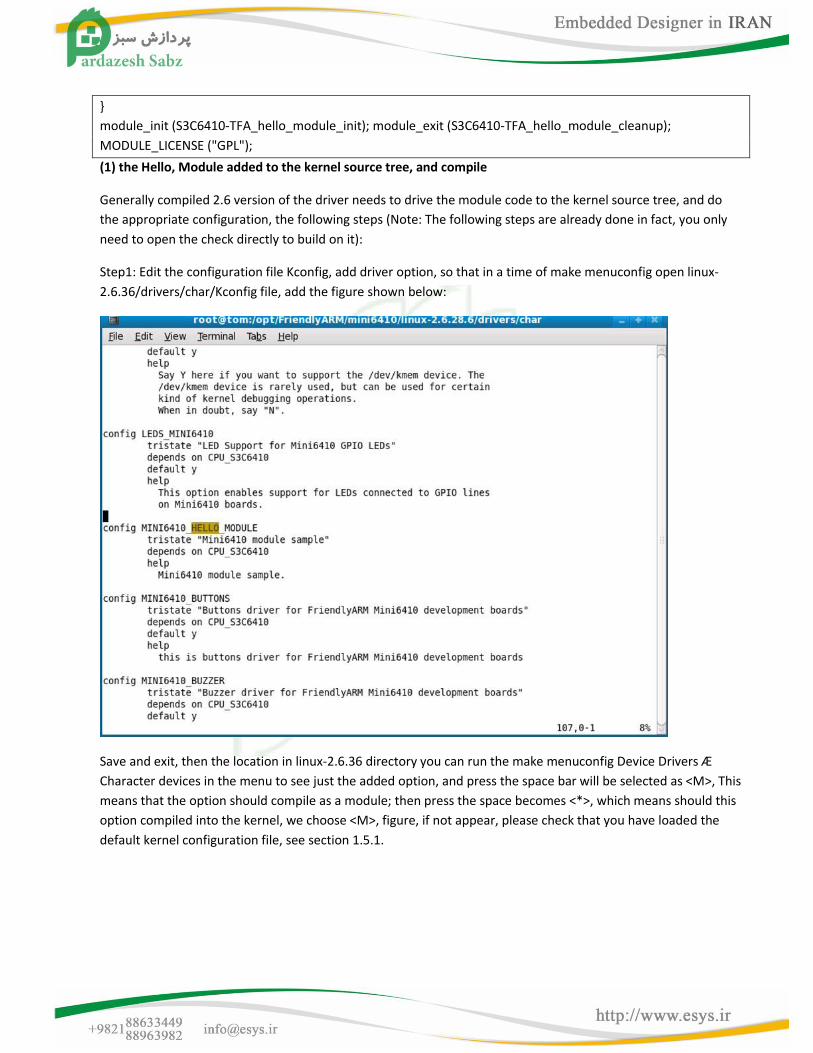
}
module_init (S3C6410-TFA_hello_module_init); module_exit (S3C6410-TFA_hello_module_cleanup);
MODULE_LICENSE ("GPL");
(1) the Hello, Module added to the kernel source tree, and compile
Generally compiled 2.6 version of the driver needs to drive the module code to the kernel source tree, and do
the appropriate configuration, the following steps (Note: The following steps are already done in fact, you only
need to open the check directly to build on it):
Step1: Edit the configuration file Kconfig, add driver option, so that in a time of make menuconfig open linux-
2.6.36/drivers/char/Kconfig file, add the figure shown below:
Save and exit, then the location in linux-2.6.36 directory you can run the make menuconfig Device Drivers Æ
Character devices in the menu to see just the added option, and press the space bar will be selected as <M>, This
means that the option should compile as a module; then press the space becomes <*>, which means should this
option compiled into the kernel, we choose <M>, figure, if not appear, please check that you have loaded the
default kernel configuration file, see section 1.5.1.
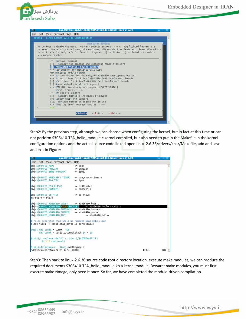
Step2: By the previous step, although we can choose when configuring the kernel, but in fact at this time or can
not perform S3C6410-TFA_hello_module.c kernel compiled, but also need to put in the Makefile in the kernel
configuration options and the actual source code linked open linux-2.6.36/drivers/char/Makefile, add and save
and exit in Figure:
Step3: Then back to linux-2.6.36 source code root directory location, execute make modules, we can produce the
required documents S3C6410-TFA_hello_module.ko a kernel module, Beware: make modules, you must first
execute make zImage, only need it once. So far, we have completed the module-driven compilation.
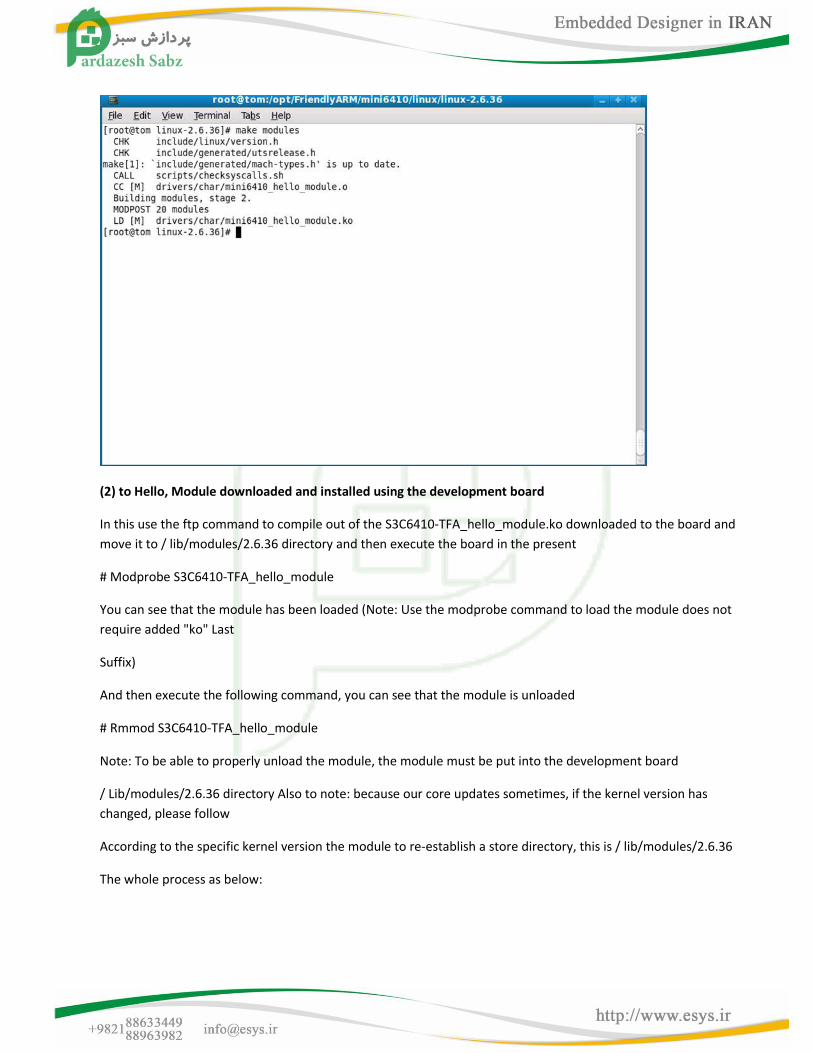
(2) to Hello, Module downloaded and installed using the development board
In this use the ftp command to compile out of the S3C6410-TFA_hello_module.ko downloaded to the board and
move it to / lib/modules/2.6.36 directory and then execute the board in the present
# Modprobe S3C6410-TFA_hello_module
You can see that the module has been loaded (Note: Use the modprobe command to load the module does not
require added "ko" Last
Suffix)
And then execute the following command, you can see that the module is unloaded
# Rmmod S3C6410-TFA_hello_module
Note: To be able to properly unload the module, the module must be put into the development board
/ Lib/modules/2.6.36 directory Also to note: because our core updates sometimes, if the kernel version has
changed, please follow
According to the specific kernel version the module to re-establish a store directory, this is / lib/modules/2.6.36
The whole process as below:
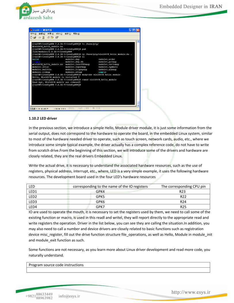
1.10.2 LED driver
In the previous section, we introduce a simple Hello, Module driver module, it is just some information from the
serial output, does not correspond to the hardware to operate the board, in the embedded Linux system, similar
to most of the hardware needed driver to operate, such as touch screen, network cards, audio, etc., where we
introduce some simple typical example, the driver actually has a complex reference code, do not have to write
from scratch drive.From the beginning of this section, we will introduce some of the drivers and hardware are
closely related, they are the real drivers Embedded Linux.
Write the actual drive, it is necessary to understand the associated hardware resources, such as the use of
registers, physical address, interrupt, etc., where, LED is a very simple example, it uses the following hardware
resources. The development board used in the four LED's hardware resources
LED corresponding to the name of the IO registers The corresponding CPU pin
LED1 GPK4 R23
LED2 GPK5 R22
LED3 GPK6 R24
LED4 GPK7 R25
IO are used to operate the mouth, it is necessary to set the registers used by them, we need to call some of the
existing function or macro, is used in this readl and writel, they will report directly to the appropriate read and
write registers the operation. Driver in the list below, you can see they are calling the situation.In addition, you
may also need to call a number and device drivers are closely related to basic functions such as registration
device misc_register, fill out the drive function structure file_operations, as well as Hello, Module in module_init
and module_exit function as such.
Some functions are not necessary, as you learn more about Linux driver development and read more code, you
naturally understand.
Program source code instructions
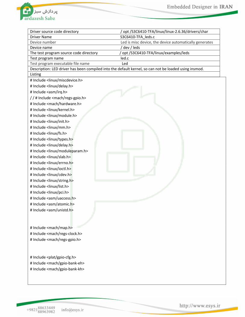
Driver source code directory / opt /S3C6410-TFA/linux/linux-2.6.36/drivers/char
Driver Name S3C6410-TFA_leds.c
Device number Led is misc device, the device automatically generates
Device name / dev / leds
The test program source code directory / opt /S3C6410-TFA/linux/examples/leds
Test program name led.c
Test program executable file name Led
Description: LED driver has been compiled into the default kernel, so can not be loaded using insmod.
Listing
# Include <linux/miscdevice.h>
# Include <linux/delay.h>
# Include <asm/irq.h>
/ / # Include <mach/regs-gpio.h>
# Include <mach/hardware.h>
# Include <linux/kernel.h>
# Include <linux/module.h>
# Include <linux/init.h>
# Include <linux/mm.h>
# Include <linux/fs.h>
# Include <linux/types.h>
# Include <linux/delay.h>
# Include <linux/moduleparam.h>
# Include <linux/slab.h>
# Include <linux/errno.h>
# Include <linux/ioctl.h>
# Include <linux/cdev.h>
# Include <linux/string.h>
# Include <linux/list.h>
# Include <linux/pci.h>
# Include <asm/uaccess.h>
# Include <asm/atomic.h>
# Include <asm/unistd.h>
# Include <mach/map.h>
# Include <mach/regs-clock.h>
# Include <mach/regs-gpio.h>
# Include <plat/gpio-cfg.h>
# Include <mach/gpio-bank-eh>
# Include <mach/gpio-bank-kh>
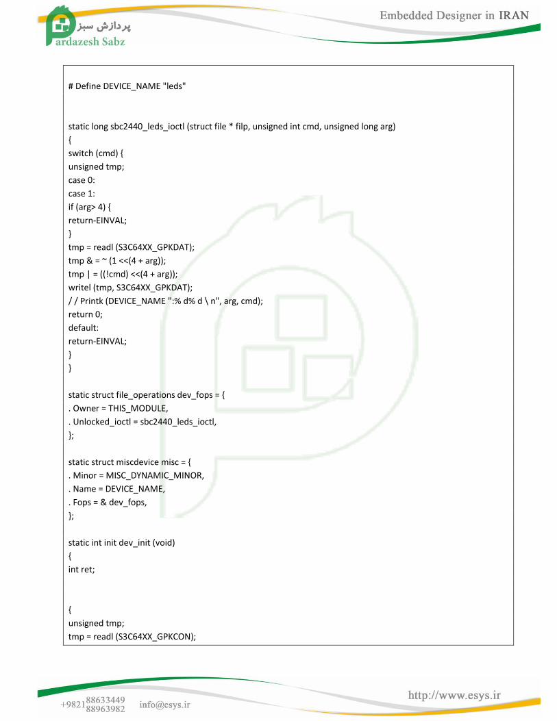
# Define DEVICE_NAME "leds"
static long sbc2440_leds_ioctl (struct file * filp, unsigned int cmd, unsigned long arg)
{
switch (cmd) {
unsigned tmp;
case 0:
case 1:
if (arg> 4) {
return-EINVAL;
}
tmp = readl (S3C64XX_GPKDAT);
tmp & = ~ (1 <<(4 + arg));
tmp | = ((!cmd) <<(4 + arg));
writel (tmp, S3C64XX_GPKDAT);
/ / Printk (DEVICE_NAME ":% d% d \ n", arg, cmd);
return 0;
default:
return-EINVAL;
}
}
static struct file_operations dev_fops = {
. Owner = THIS_MODULE,
. Unlocked_ioctl = sbc2440_leds_ioctl,
};
static struct miscdevice misc = {
. Minor = MISC_DYNAMIC_MINOR,
. Name = DEVICE_NAME,
. Fops = & dev_fops,
};
static int init dev_init (void)
{
int ret;
{
unsigned tmp;
tmp = readl (S3C64XX_GPKCON);
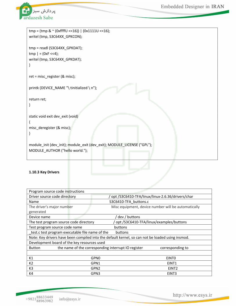
tmp = (tmp & ~ (0xffffU <<16)) | (0x1111U <<16);
writel (tmp, S3C64XX_GPKCON);
tmp = readl (S3C64XX_GPKDAT);
tmp | = (0xF <<4);
writel (tmp, S3C64XX_GPKDAT);
}
ret = misc_register (& misc);
printk (DEVICE_NAME "\ tinitialized \ n");
return ret;
}
static void exit dev_exit (void)
{
misc_deregister (& misc);
}
module_init (dev_init); module_exit (dev_exit); MODULE_LICENSE ("GPL");
MODULE_AUTHOR ("hello world.");
1.10.3 Key Drivers
Program source code instructions
Driver source code directory / opt /S3C6410-TFA/linux/linux-2.6.36/drivers/char
Name S3C6410-TFA_buttons.c
The driver's major number Misc equipment, device number will be automatically generated
Device name / dev / buttons
The test program source code directory / opt /S3C6410-TFA/linux/examples/buttons
Test program source code name buttons
_test.c test program executable file name of the buttons
Note: Key drivers have been compiled into the default kernel, so can not be loaded using insmod.
Development board of the key resources used
Button the name of the corresponding interrupt IO register corresponding to
K1 GPN0 EINT0
K2 GPN1 EINT1
K3 GPN2 EINT2
K4 GPN3 EINT3
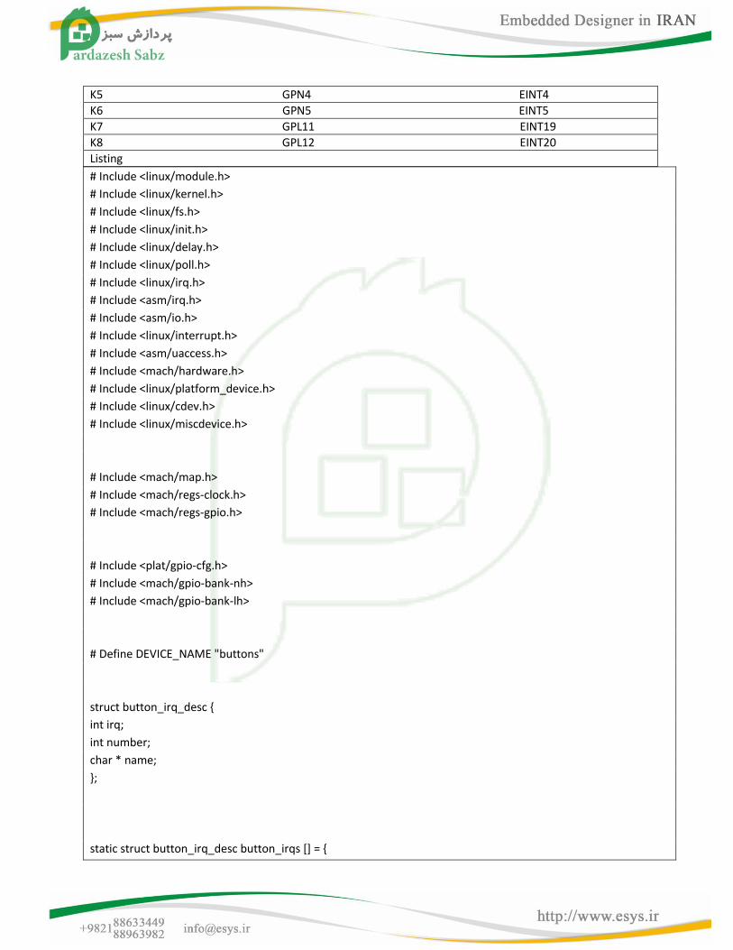
K5 GPN4 EINT4
K6 GPN5 EINT5
K7 GPL11 EINT19
K8 GPL12 EINT20
Listing
# Include <linux/module.h>
# Include <linux/kernel.h>
# Include <linux/fs.h>
# Include <linux/init.h>
# Include <linux/delay.h>
# Include <linux/poll.h>
# Include <linux/irq.h>
# Include <asm/irq.h>
# Include <asm/io.h>
# Include <linux/interrupt.h>
# Include <asm/uaccess.h>
# Include <mach/hardware.h>
# Include <linux/platform_device.h>
# Include <linux/cdev.h>
# Include <linux/miscdevice.h>
# Include <mach/map.h>
# Include <mach/regs-clock.h>
# Include <mach/regs-gpio.h>
# Include <plat/gpio-cfg.h>
# Include <mach/gpio-bank-nh>
# Include <mach/gpio-bank-lh>
# Define DEVICE_NAME "buttons"
struct button_irq_desc {
int irq;
int number;
char * name;
};
static struct button_irq_desc button_irqs [] = {

{IRQ_EINT (0), 0, "KEY0"},
{IRQ_EINT (1), 1, "KEY1"},
{IRQ_EINT (2), 2, "KEY2"},
{IRQ_EINT (3), 3, "KEY3"},
{IRQ_EINT (4), 4, "KEY4"},
{IRQ_EINT (5), 5, "KEY5"},
{IRQ_EINT (19), 6, "KEY6"},
{IRQ_EINT (20), 7, "KEY7"},
};
static volatile char key_values [] = {'0 ', '0', '0 ', '0', '0 ', '0', '0 ', '0'};
static DECLARE_WAIT_QUEUE_HEAD (button_waitq);
static volatile int ev_press = 0;
static irqreturn_t buttons_interrupt (int irq, void * dev_id)
{
struct button_irq_desc * button_irqs = (struct button_irq_desc *) dev_id;
int down; int number; unsigned tmp;
udelay (0);
number = button_irqs-> number;
switch (number) {
case 0: case 1: case 2: case 3: case 4: case 5: tmp = readl (S3C64XX_GPNDAT); down =! (tmp & (1 <<number));
break;
case 6: case 7:
tmp = readl (S3C64XX_GPLDAT); down =! (tmp & (1 <<(number + 5))); break;
default:
down = 0;
}
if (down!= (Key_values [number] & 1)) {
key_values [number] = '0 '+ down;
ev_press = 1;
wake_up_interruptible (& button_waitq);
}
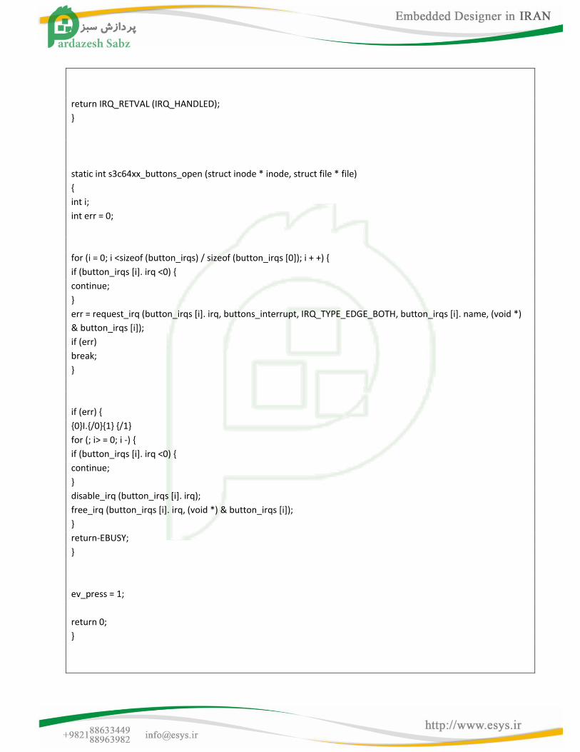
return IRQ_RETVAL (IRQ_HANDLED);
}
static int s3c64xx_buttons_open (struct inode * inode, struct file * file)
{
int i;
int err = 0;
for (i = 0; i <sizeof (button_irqs) / sizeof (button_irqs [0]); i + +) {
if (button_irqs [i]. irq <0) {
continue;
}
err = request_irq (button_irqs [i]. irq, buttons_interrupt, IRQ_TYPE_EDGE_BOTH, button_irqs [i]. name, (void *)
& button_irqs [i]);
if (err)
break;
}
if (err) {
{0}I.{/0}{1} {/1}
for (; i> = 0; i -) {
if (button_irqs [i]. irq <0) {
continue;
}
disable_irq (button_irqs [i]. irq);
free_irq (button_irqs [i]. irq, (void *) & button_irqs [i]);
}
return-EBUSY;
}
ev_press = 1;
return 0;
}

static int s3c64xx_buttons_close (struct inode * inode, struct file * file)
{
int i;
for (i = 0; i <sizeof (button_irqs) / sizeof (button_irqs [0]); i + +) {
if (button_irqs [i]. irq <0) {
continue;
}
free_irq (button_irqs [i]. irq, (void *) & button_irqs [i]);
}
return 0;
}
static int s3c64xx_buttons_read (struct file * filp, char user * buff, size_t count, loff_t * offp)
{
unsigned long err;
if (!ev_press) {
if (filp-> f_flags & O_NONBLOCK)
return-EAGAIN;
else
}
wait_event_interruptible (button_waitq, ev_press);
ev_press = 0;
err = copy_to_user ((void *) buff, (const void *) (& key_values), min (sizeof (key_values), count));
return err?-EFAULT: min (sizeof (key_values), count);
}
static unsigned int s3c64xx_buttons_poll (struct file * file, struct poll_table_struct * wait)
{
unsigned int mask = 0;
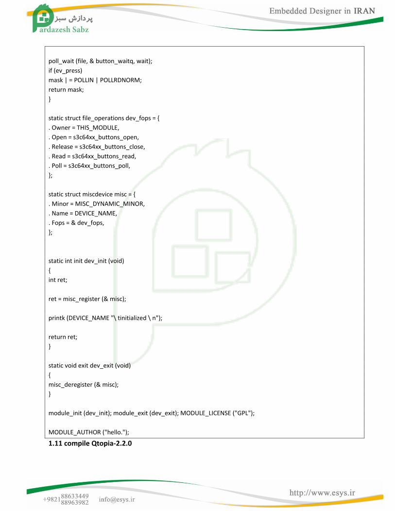
poll_wait (file, & button_waitq, wait);
if (ev_press)
mask | = POLLIN | POLLRDNORM;
return mask;
}
static struct file_operations dev_fops = {
. Owner = THIS_MODULE,
. Open = s3c64xx_buttons_open,
. Release = s3c64xx_buttons_close,
. Read = s3c64xx_buttons_read,
. Poll = s3c64xx_buttons_poll,
};
static struct miscdevice misc = {
. Minor = MISC_DYNAMIC_MINOR,
. Name = DEVICE_NAME,
. Fops = & dev_fops,
};
static int init dev_init (void)
{
int ret;
ret = misc_register (& misc);
printk (DEVICE_NAME "\ tinitialized \ n");
return ret;
}
static void exit dev_exit (void)
{
misc_deregister (& misc);
}
module_init (dev_init); module_exit (dev_exit); MODULE_LICENSE ("GPL");
MODULE_AUTHOR ("hello.");
1.11 compile Qtopia-2.2.0

Qtopia-2.2.0 compile because of the configuration process is more complex, in order to facilitate beginners to
learn and easy to use, we make the steps to configure and compile into a build script, simply run the script to
compile the Qtopia platform, and to their own all applets; by "run" script you can run them, x86 and arm version
of the steps are basically the same, but the script content is slightly different, the steps are detailed below.
1.11.1 extracting installer source code
See section 1.4.1
1.11.2 Compiling and running the x86 version of Qtopia-2.2.0
Letter to: develop and test our software platform to develop all based Fedora9, all configuration and build scripts
are based on this platform, we have not tested on other platforms.If you are familiar with Linux development
Hen, I believe you will find step by step according to error causes and solutions, they generally lack the platform
you use some libraries or tools and other causes; Otherwise, we recommend beginners to use and we agreed
platform, that Fedora 9 (full name: Fedora-9-i386-DVD.iso), you can download at its official website
(ftp://download.fedora.redhat.com/pub/fedora/linux/releases/9 / Fedora/i386/iso/Fedora-9-i386-DVD
. Iso, does not guarantee long-term effective), you can get in other places, they are the same, be sure to refer to
our installation manual provides step, which is the result of rigorous testing, so as not to miss some of the
development of the group when needed pieces.
Many Linux distributions, we can not write this document explains installation of eleven, please understand.
Into the working directory, execute the following command
# Cd / opt /S3C6410-TFA/linux/x86-qtopia
#. / Build-all (the process is long, you need to run about 30 minutes)
Description:. / Build-all will automatically compile a complete and Qtopia embedded browser, you can have
execute. / Build
And. / Build-konq script command to compile them separately, if you do not have the smooth implementation,
please refer to the above description of the red font.
Command:
You just want to run out of Qtopia build system is very simple, just the compiled command in the terminal, enter
the following #. / Run; note that "/" in front of a ".", Which means that the implementation in the current
directory then you can see the following interface
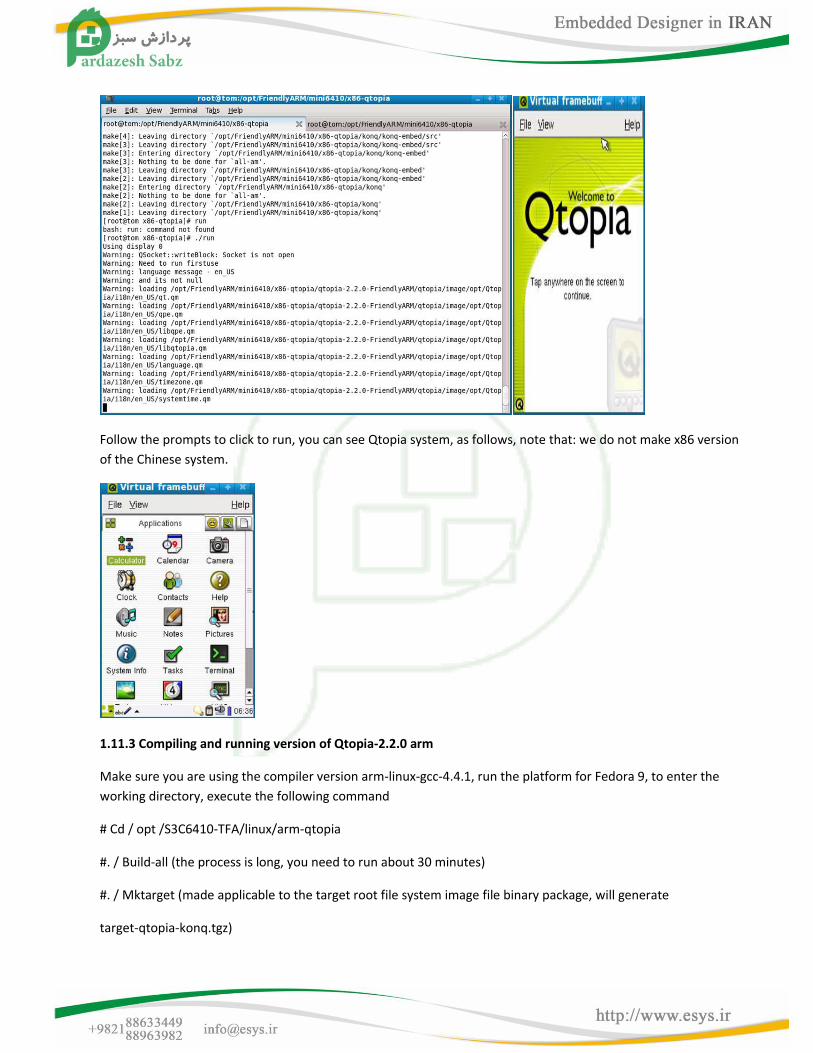
Follow the prompts to click to run, you can see Qtopia system, as follows, note that: we do not make x86 version
of the Chinese system.
1.11.3 Compiling and running version of Qtopia-2.2.0 arm
Make sure you are using the compiler version arm-linux-gcc-4.4.1, run the platform for Fedora 9, to enter the
working directory, execute the following command
# Cd / opt /S3C6410-TFA/linux/arm-qtopia
#. / Build-all (the process is long, you need to run about 30 minutes)
#. / Mktarget (made applicable to the target root file system image file binary package, will generate
target-qtopia-konq.tgz)
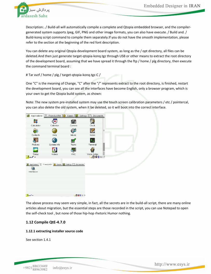
Description:. / Build-all will automatically compile a complete and Qtopia embedded browser, and the compiler-
generated system supports Jpeg, GIF, PNG and other image formats, you can also have execute. / Build and. /
Build-konq script command to compile them separately.If you do not have the smooth implementation, please
refer to the section at the beginning of the red font description.
You can delete any original Qtopia development board system, as long as the / opt directory, all files can be
deleted.And then just generate target-qtopia-konq.tgz through USB or other means to extract the root directory
of the development board, assuming that we have spread it through the ftp / home / plg directory, then execute
the command terminal board :
# Tar xvzf / home / plg / target-qtopia-konq.tgz-C /
One "C" is the meaning of Change, "C" after the "/" represents extract to the root directory, is finished, restart
the development board, you can see all the interfaces have become English, only a browser program, which is
your own to get the Qtopia build system, as shown:
Note: The new system pre-installed system may use the touch screen calibration parameters / etc / pointercal,
you can also delete the old system, when it be deleted, so it will boot into the correct interface.
The above process may seem very simple, in fact, all the secrets are in the build-all script, there are many online
articles about migration, but the essential steps are those recorded in the script, you can use Notepad to open
the self-check tool , but none of those hip-hop rhetoric Humor nothing.
1.12 Compile QtE-4.7.0
1.12.1 extracting installer source code
See section 1.4.1
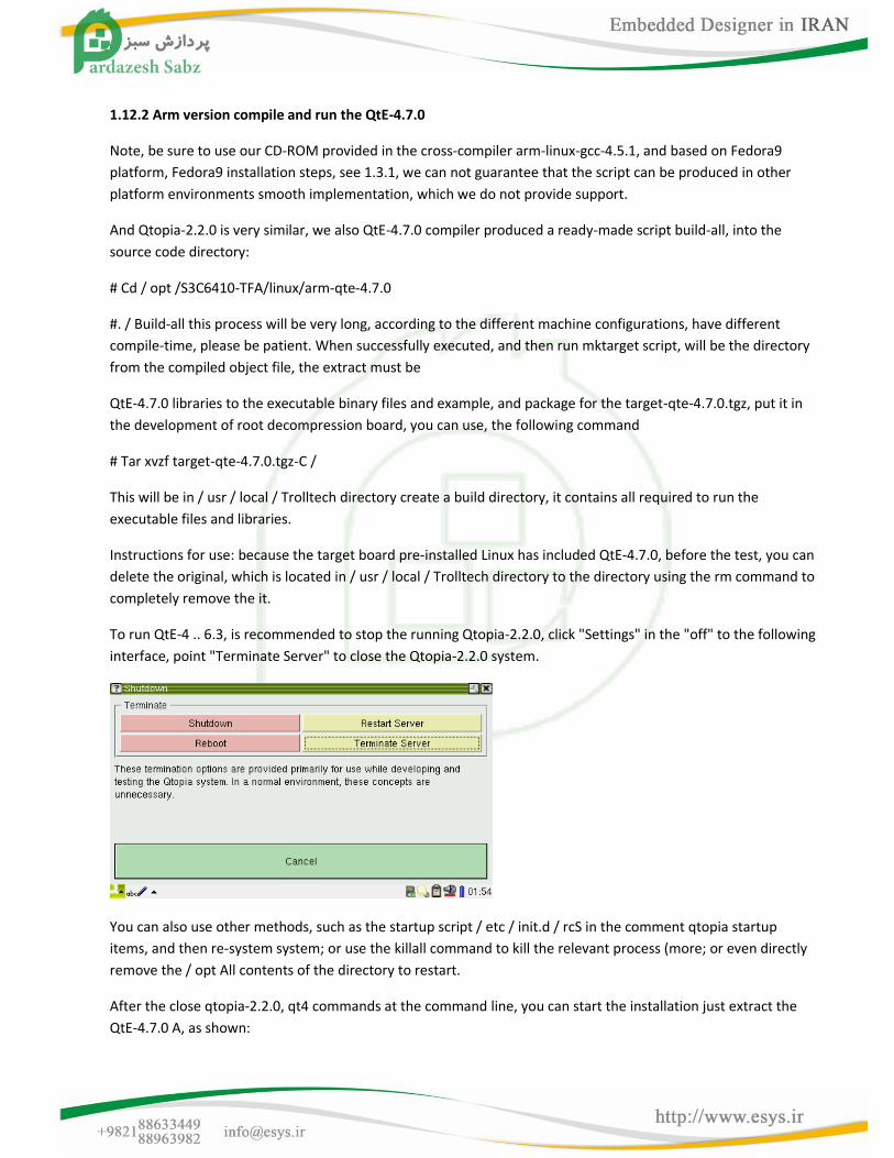
1.12.2 Arm version compile and run the QtE-4.7.0
Note, be sure to use our CD-ROM provided in the cross-compiler arm-linux-gcc-4.5.1, and based on Fedora9
platform, Fedora9 installation steps, see 1.3.1, we can not guarantee that the script can be produced in other
platform environments smooth implementation, which we do not provide support.
And Qtopia-2.2.0 is very similar, we also QtE-4.7.0 compiler produced a ready-made script build-all, into the
source code directory:
# Cd / opt /S3C6410-TFA/linux/arm-qte-4.7.0
#. / Build-all this process will be very long, according to the different machine configurations, have different
compile-time, please be patient. When successfully executed, and then run mktarget script, will be the directory
from the compiled object file, the extract must be
QtE-4.7.0 libraries to the executable binary files and example, and package for the target-qte-4.7.0.tgz, put it in
the development of root decompression board, you can use, the following command
# Tar xvzf target-qte-4.7.0.tgz-C /
This will be in / usr / local / Trolltech directory create a build directory, it contains all required to run the
executable files and libraries.
Instructions for use: because the target board pre-installed Linux has included QtE-4.7.0, before the test, you can
delete the original, which is located in / usr / local / Trolltech directory to the directory using the rm command to
completely remove the it.
To run QtE-4 .. 6.3, is recommended to stop the running Qtopia-2.2.0, click "Settings" in the "off" to the following
interface, point "Terminate Server" to close the Qtopia-2.2.0 system.
You can also use other methods, such as the startup script / etc / init.d / rcS in the comment qtopia startup
items, and then re-system system; or use the killall command to kill the relevant process (more; or even directly
remove the / opt All contents of the directory to restart.
After the close qtopia-2.2.0, qt4 commands at the command line, you can start the installation just extract the
QtE-4.7.0 A, as shown:
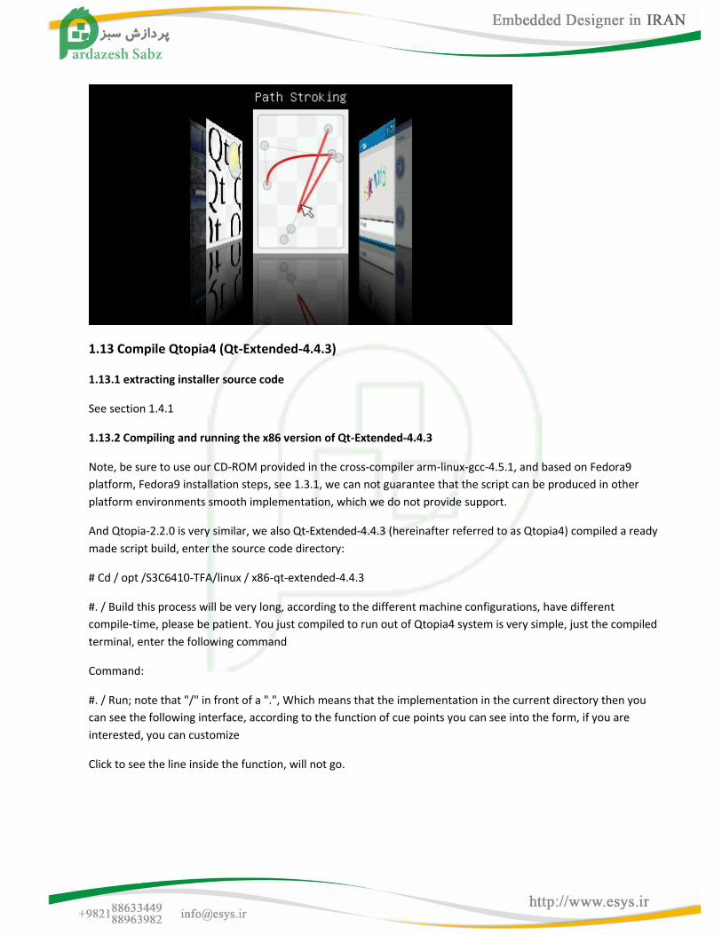
1.13 Compile Qtopia4 (Qt-Extended-4.4.3)
1.13.1 extracting installer source code
See section 1.4.1
1.13.2 Compiling and running the x86 version of Qt-Extended-4.4.3
Note, be sure to use our CD-ROM provided in the cross-compiler arm-linux-gcc-4.5.1, and based on Fedora9
platform, Fedora9 installation steps, see 1.3.1, we can not guarantee that the script can be produced in other
platform environments smooth implementation, which we do not provide support.
And Qtopia-2.2.0 is very similar, we also Qt-Extended-4.4.3 (hereinafter referred to as Qtopia4) compiled a ready
made script build, enter the source code directory:
# Cd / opt /S3C6410-TFA/linux / x86-qt-extended-4.4.3
#. / Build this process will be very long, according to the different machine configurations, have different
compile-time, please be patient. You just compiled to run out of Qtopia4 system is very simple, just the compiled
terminal, enter the following command
Command:
#. / Run; note that "/" in front of a ".", Which means that the implementation in the current directory then you
can see the following interface, according to the function of cue points you can see into the form, if you are
interested, you can customize
Click to see the line inside the function, will not go.
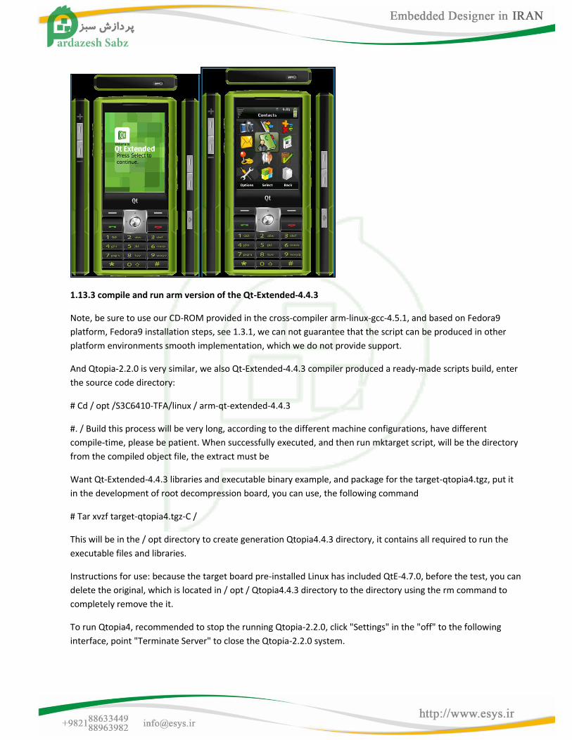
1.13.3 compile and run arm version of the Qt-Extended-4.4.3
Note, be sure to use our CD-ROM provided in the cross-compiler arm-linux-gcc-4.5.1, and based on Fedora9
platform, Fedora9 installation steps, see 1.3.1, we can not guarantee that the script can be produced in other
platform environments smooth implementation, which we do not provide support.
And Qtopia-2.2.0 is very similar, we also Qt-Extended-4.4.3 compiler produced a ready-made scripts build, enter
the source code directory:
# Cd / opt /S3C6410-TFA/linux / arm-qt-extended-4.4.3
#. / Build this process will be very long, according to the different machine configurations, have different
compile-time, please be patient. When successfully executed, and then run mktarget script, will be the directory
from the compiled object file, the extract must be
Want Qt-Extended-4.4.3 libraries and executable binary example, and package for the target-qtopia4.tgz, put it
in the development of root decompression board, you can use, the following command
# Tar xvzf target-qtopia4.tgz-C /
This will be in the / opt directory to create generation Qtopia4.4.3 directory, it contains all required to run the
executable files and libraries.
Instructions for use: because the target board pre-installed Linux has included QtE-4.7.0, before the test, you can
delete the original, which is located in / opt / Qtopia4.4.3 directory to the directory using the rm command to
completely remove the it.
To run Qtopia4, recommended to stop the running Qtopia-2.2.0, click "Settings" in the "off" to the following
interface, point "Terminate Server" to close the Qtopia-2.2.0 system.

You can also use other methods, such as the startup script / etc / init.d / rcS in the comment qtopia startup
items, and then re-system system; or use the killall command to kill the relevant process (more; or even directly
remove the / opt All contents of the directory to restart.
After the close qtopia-2.2.0, at the command line "qtopia4 &" (where "&" that runs in the background)
command, you can start just extract the installation Qtopia4, shown in Figure:
1.14 choose which version of Qt to develop
With so many versions of Qt, there are many users do not know how to choose, in fact, there is no standard
answer, we think it depends on your needs, and the latest is not good, nor is the old version it is not good.
Platform for the development board, we need a full desktop system (Qtopia desktop system is the handheld
device), so suitable for a variety of resolution on the LCD display can have a good effect, for the display of the
development board various functions, so we developed based on Qtopia-2.2.0 small programs, and implemented
and Qtopia4, QtE-4.7.0 Coexistence and other free to switch, in essence, these implementations are not very
new very stylish use of technology, They are more basic Linux C or C + + programming, graphical user interface is
just a shell, but this has met our needs.
If your application does not require complete desktop system, but a separate two applications, we recommend
using QtE-4.7 or later, because of their cross-platform development of better, it may be easier for beginners to
master and transplantation , a description is a separate application QtE-4.7 is not very large footprint.