s mmary - broaching tools - hornusa.com · broaching chamfering dimensions din type sh117 holder...
TRANSCRIPT
Width
Tolerance grade
Dm
int
Inser
tsw
Toolh
older
Tool
length
l 2 Ins
erts
Toolh
older
Tool
length
l 2
.1..2.
.3..1.
.2..3.
6C
1122
2,6
S117
.061
0.22
6,12
SH11
7.00
25...
1050
70S1
17.3
045.
10SH
117.
0025
...10
5070
7C
1127
3,3
S117
.071
0.27
7,13
SH11
7.00
25...
1050
70S1
17.3
045.
10SH
117.
0025
...10
5070
8C
1132
3,4
S117
.081
0.32
8,13
SH11
7.00
25...
1050
70S1
17.3
045.
10SH
117.
0025
...10
5070
10C
1140
4,2
S117
.101
4.40
10,1
3SH
117.
0032
...16
5075
100
S117
.604
5.14
SH11
7.00
32...
1650
7510
0
12C
1150
5,1
S117
.121
4.50
12,1
5SH
117.
0032
...16
5075
100
S117
.604
5.14
SH11
7.00
32...
1650
7510
0
16C
1170
6,6
S117
.161
4.70
12,1
5SH
117.
0032
...16
5075
100
S117
.604
5.14
SH11
7.00
32...
1650
7510
0
24C
1110
08,
5S1
17.2
414.
100
12,1
5SH
117.
0032
...16
5075
100
S117
.604
5.14
SH11
7.00
32...
1650
7510
0
5P9
172,
7S1
17.0
497.
02.1
04,
98SH
117.
1725
...10
4055
S117
.154
5.10
SH11
7.17
25...
1040
556
P917
3,4
S117
.059
7.02
.10
5,98
SH11
7.17
25...
1040
55S1
17.1
545.
10SH
117.
1725
...10
4055
8P9
224,
1S1
17.0
796.
02.1
07,
98SH
117.
0025
...10
5070
S117
.304
5.10
SH11
7.00
25...
1050
70
10P9
304,
2S1
17.0
996.
03.1
49,
98SH
117.
3032
...16
5075
100
S117
.604
5.14
SH11
7.30
32...
1650
7510
0
12P9
385,
7S1
17.1
196.
03.1
411
,97
SH11
7.00
32...
1650
7510
0S1
17.6
045.
14SH
117.
0032
...16
5075
100
14P9
406,
8S1
17.1
396.
03.1
613
,97
SH11
7.40
32...
1650
7510
0S1
17.6
045.
14SH
117.
0032
...16
5075
100
5JS
917
2,7
S117
.050
0.02
.10
5,01
SH11
7.17
25...
1040
55S1
17.1
545.
10SH
117.
1725
...10
4055
6JS
917
3,4
S117
.060
0.02
.10
6,01
SH11
7.17
25...
1040
55S1
17.1
545.
10SH
117.
1725
...10
4055
8JS
922
4,1
S117
.080
0.02
.10
8,01
SH11
7.00
25...
1050
70S1
17.3
045.
10SH
117.
0025
...10
5070
10JS
930
4,2
S117
.100
0.03
.14
10,0
1SH
117.
3032
...16
5075
100
S117
.604
5.14
SH11
7.30
32...
1650
7510
0
12JS
938
5,7
S117
.120
0.03
.14
12,0
1SH
117.
0032
...16
5075
100
S117
.604
5.14
SH11
7.00
32...
1650
7510
0
12JS
938
8,5
S117
.120
0.05
.14
12,0
0SH
117.
0032
...16
5075
100
S117
.604
5.14
SH11
7.00
32...
1650
7510
0
14JS
940
6,8
S117
.140
0.03
.16
14,0
1SH
117.
4032
...16
5075
100
S117
.604
5.14
SH11
7.00
32...
1650
7510
0
In the UNITED STATES call us toll free1 - 888 - 818 HORN
SU MMARY - BROACHING TOOLS
Broa
ching
Cham
fering
Dime
nsion
s DIN
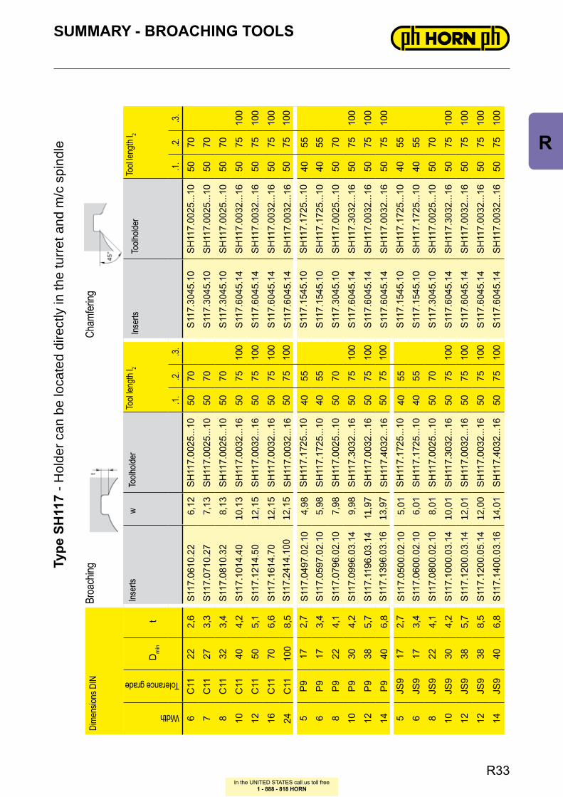
Type
SH
117
- Hol
der c
an b
e lo
cate
d di
rect
ly in
the
turr
et a
nd m
/c s
pind
le
R33
R
In the UNITED STATES call us toll free1 - 888 - 818 HORN
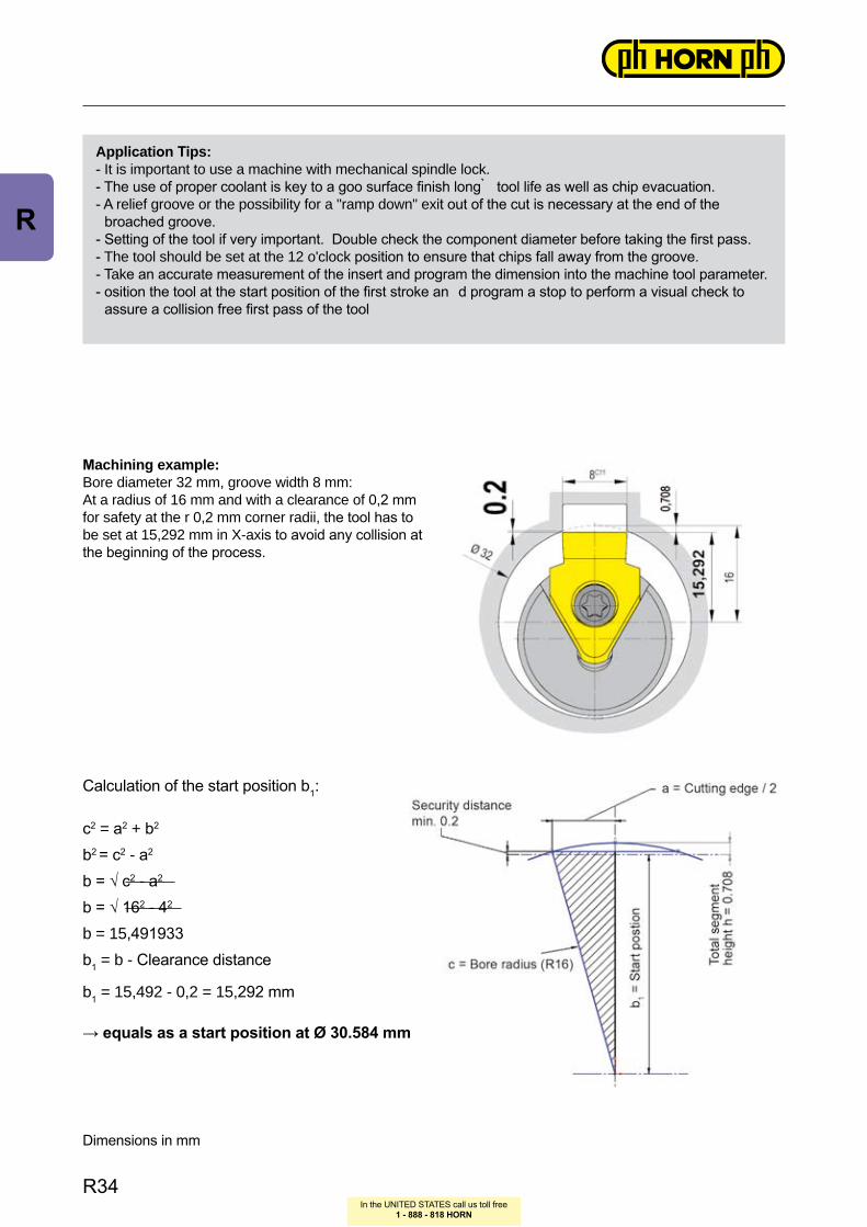
Mac hini ng ex ampl e:Bore diameter 32 mm, groove width 8 mm:At a radius of 16 mm and with a clearance of 0, 2 mm for safety at the r 0, 2 mm corner radii, the tool has to be set at 15, 292 mm in X- ax is to avoid any collision at the beginning of the process.
c2 = a2 + b2
b2 = c2 - a2
b = √ c2 - a2
b = √ 162 - 42
b = 15, 491933b1 = b - Clearance distance
b1 = 15, 492 - 0, 2 = 15, 292 mm
→ equals as a start position at Ø 30.584 mm
Calculation of the start position b1:
Dimensions in mm
Appl icati on Tips:- It is important to use a machine with mechanical spindle lock .- The use of proper coolant is key to a goo surface finish long ̀ tool life as well as chip evacuation.- A relief groove or the possibility for a "ramp down" ex it out of the cut is necessary at the end of the broached groove.- Setting of the tool if very important. Double check the component diameter before taking the first pass.- The tool should be set at the 12 o' clock position to ensure that chips fall away from the groove.- Tak e an accurate measurement of the insert and program the dimension into the machine tool parameter.- osition the tool at the start position of the first stroke an d program a stop to perform a visual check to assure a collision free first pass of the tool
R34
R
In the UNITED STATES call us toll free1 - 888 - 818 HORN
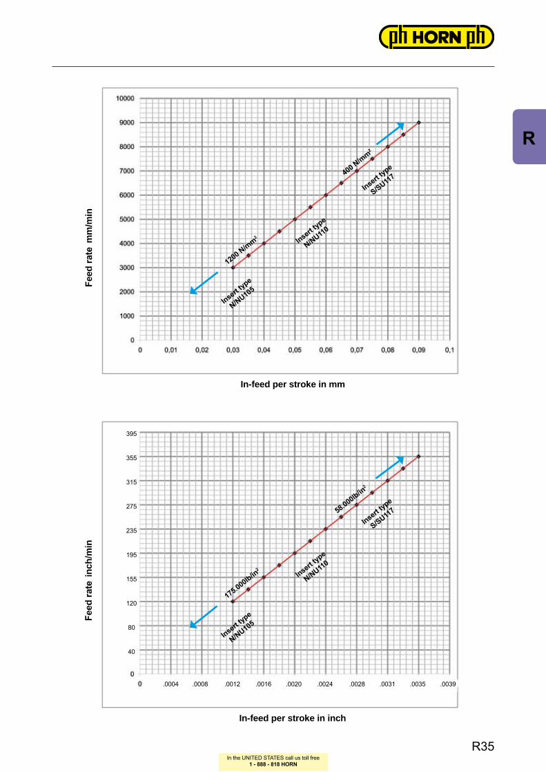
Feed
rate
mm
/min
Fe
ed ra
te in
ch/m
in
In-f eed per stro ke i n mm
In-f eed per stro ke i n i nc h
1200 N/mm
2
175.000lb/in2
.0004 .0008 .0012 .0016 .0020 .0024 .0028 .0031 .0035 .0039
395
355
315
275
235
195
155
120
80
40
400 N/mm
2
58.000lb/in2
Insert type
N/NU105
Insert type
N/NU105
Insert type
N/NU110
Insert type
N/NU110
Insert type
S/SU117
Insert type
S/SU117
R35
R
In the UNITED STATES call us toll free1 - 888 - 818 HORN
PROGRAM MING EX AM PLE
Ex ampl e f or bro ac hing o n a TRAU B TNA 400 w ith C-Ax is
NC - Program
N……(BROACHING) Sequence Number and Application
G97 T… … M5 constant RPM , Tool callout, Spindle Stop
M17 C - ax is ON
G94 Feed Rate in mm/ min
L1 = 30.584 choose Parameter for start Ø
M8 M 19 Coolant ON, Spindle Break ON
N100 Sequence Number for repetition START
G0 XL1 Z 5 Start position in X and Z in front of part
G1 Z -25 F8000 Linear move in Z at feed rate of 8000 mm/ min
G0 X30.584 Rapid move in X to start Ø i.e. drop down position
G0 Z 5 Rapid move in Z to start position.
L1 = L1+ 0.16 As Ø programming is in effect the depth of cut must be doubled (Depth of Cut is 0.08 mm)
N200 Sequence Number of repetition END.
G22 P100 Q 200 H45 Repetition Cycle with Sequence Number from START to END and Number of repetitions
Ex ample:
- Groove according to table in bore Ø 32 mm- Groove width 8C11
- Depth of Cut per Strok e 0.08 mm- The Number o f Stro kes resulted out of complete cutting depth from start position to the bottom of the groove divided by depth of cut per strok e- This . alue must then be multiplied by 2 ( because Ø Programming) and Value is programmed as the Number of Strok es in the NC- Programme.
Calculation:
- Starting Position = Security Distance + Distance from Ø 32 mm to Cutting Edge (see Example on Page R34) equals a segment height of 0.508 mm + Security Distance of 0.20 mm to a total of 0.708 mm.- Starting Position = 30.584 mm (32 - [0.708 x 2] = 30.584 mm.- The groove depth of 2.90 mm added to the 0.708 mm = 3.608 mm.- This is the dimension from the starting position to the bottom of the groove and in order to program this on the Ø, the 3.608 mm dimension must be mul ti pl ied by 2 which will equal the sum of 7.216 mm.- When the 7.216 mm is divided by (2 x 0.08 mm) = 0.16 mm depth per strok e the Result will be 45.1 Stro kes and therefore 45 to tal Stro kes are programmed.The remainder of 0.1 Strokes to achieve the finish dimension must be programmed using the fine correction.
Attenti on: Th e true d epth o f c ut f or th e i nsert w ill be 0.08 mm.
R36
R
In the UNITED STATES call us toll free1 - 888 - 818 HORN
PROGRAM MING EX AM PLE
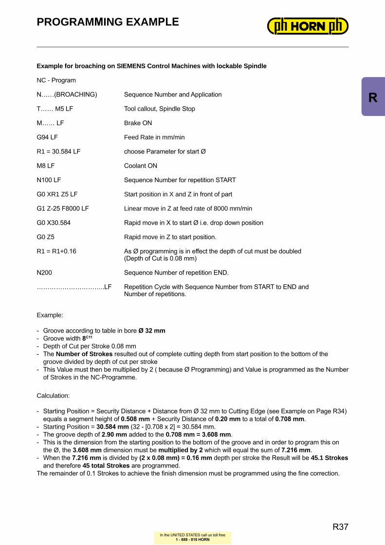
Ex ampl e f or bro ac hing o n SIEM ENS Co ntro l M ac hines w ith l ockabl e Spi nd le
NC - Program
N……(BROACHING) Sequence Number and Application
T… … M 5 LF Tool callout, Spindle Stop
M… … LF Brak e ON
G94 LF Feed Rate in mm/ min
R1 = 30.584 LF choose Parameter for start Ø
M8 LF Coolant ON
N100 LF Sequence Number for repetition START
G0 XR1 Z 5 LF Start position in X and Z in front of part
G1 Z -25 F8000 LF Linear move in Z at feed rate of 8000 mm/ min
G0 X30.584 Rapid move in X to start Ø i.e. drop down position
G0 Z 5 Rapid move in Z to start position.
R1 = R1+ 0.16 As Ø programming is in effect the depth of cut must be doubled (Depth of Cut is 0.08 mm)
N200 Sequence Number of repetition END.
… … … … … … … … … … ..LF Repetition Cycle with Sequence Number from START to END and Number of repetitions.
Ex ample:
- Groove according to table in bore Ø 32 mm- Groove width 8C11
- Depth of Cut per Strok e 0.08 mm- The Number o f Stro kes resulted out of complete cutting depth from start position to the bottom of the groove divided by depth of cut per strok e- This Value must then be multiplied by 2 ( because Ø Programming) and Value is programmed as the Number of Strok es in the NC- Programme.
Calculation:
- Starting Position = Security Distance + Distance from Ø 32 mm to Cutting Edge (see Example on Page R34) equals a segment height of 0.508 mm + Security Distance of 0.20 mm to a total of 0.708 mm.- Starting Position = 30.584 mm (32 - [0.708 x 2] = 30.584 mm.- The groove depth of 2.90 mm added to the 0.708 mm = 3.608 mm.- This is the dimension from the starting position to the bottom of the groove and in order to program this on the Ø, the 3.608 mm dimension must be mul ti pl ied by 2 which will equal the sum of 7.216 mm.- When the 7.216 mm is divided by (2 x 0.08 mm) = 0.16 mm depth per strok e the Result will be 45.1 Stro kes and therefore 45 to tal Stro kes are programmed.The remainder of 0.1 Strokes to achieve the finish dimension must be programmed using the fine correction.
R37
R
0110
2030
4010
2030
4001
1020
30
Steel
Stainless steel
Grey cast iron /
Alum
inum
In the UNITED STATES call us toll free1 - 888 - 818 HORN
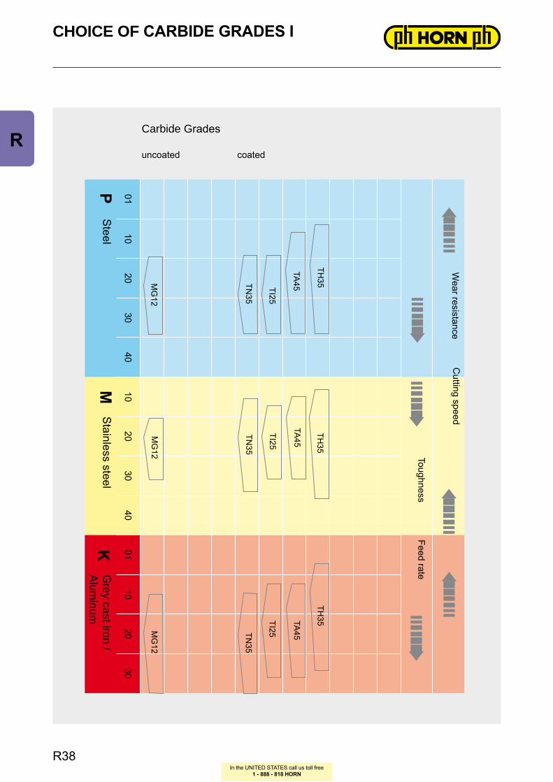
CHOICE OF CARBIDE GRADES I
Carbide G rades
uncoated coated
PM
K
TA45TI25
TN35
TA45
TI25
TN35
MG
12M
G12
Feed rate
Wear resistance
MG
12
TH35
TH35
Cutting speed
Toughness
TA45
TI25TN35
TH35
R38
R
0110
2030
4010
2030
4001
1020
30
Non
ferr
ous
met
als
Hig
h te
mp.
allo
ysH
arde
ned
mat
eria
ls
In the UNITED STATES call us toll free1 - 888 - 818 HORN
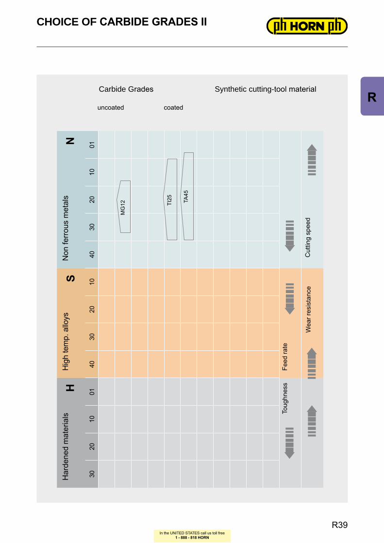
Synthetic cutting- tool material
NS
H
MG
12 TI25 TA
45
CHOICE OF CARBIDE GRADES II
Feed
rate
Wea
r res
ista
nce
Cut
ting
spee
d
Toug
hnes
s
Carbide G rades
uncoated coated
R39
R

In the UNITED STATES call us toll free1 - 888 - 818 HORN
CARBIDE GRADES
UNCOATED GRADESMG12 - a universal grade with good wear resistance. Used at low or medium cutting
speeds for machining steel, cast iron and non ferrous materials
COATED GRADESa very popular grade TiN coated used to low or medium cutting speeds. Also recommanded for machining stainless steel or exo tic alloyed materials
TN35 -
TI25 - a TiCN coated grade with high abrasion resistance. Recommended for machining steel and non ferrous materials at medium cutting speeds
TA45 - a TiAlN coated grade. This coating has a very high temperature stability and high hardness.
TH35 - new standard grade - ext reme Oxi dation resistance with high hardness and very good coefficient of friction.
R40
R