ruukki load bearing profiled sheet installation instructions
DESCRIPTION
Ruukki Load Bearing Profiled Sheet Installation InstructionsTRANSCRIPT
Ruukki is a metals expert you can rely on all the way, whenever you need metal based materials, components, systems or total solutions. We constantly develop our product range and operating models to match your needs.
Load-bearing profiled sheetInstallation instructions
Profiled sheets can be used in roof structures, both as water roofing and as load-bearing structures. The choice is made based on appearance and the required stiffness and the loads the building is subjected to. Load-bearing profiled sheets are used in both insulated and uninsulated roofs as well in the floors of buildings.
External quality control is carried out by VTT Technical Research Centre of Finland according to the quality control agreement. End-use applications• logistics buildings and warehouses• industrial buildings• retail parks• sport facilities• agricultural buildings
CFI 00.000 FI/01.20091
Installation instructions, load-bearing profiled sheets
CFI 00.000 FI/01.2009
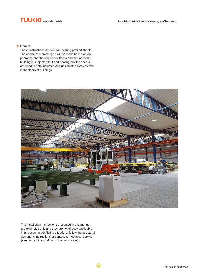
• General These instructions are for load-bearing profiled sheets.
The choice of a profile type will be made based on ap-pearance and the required stiffness and the loads the building is subjected to. Load-bearing profiled sheets are used in both insulated and uninsulated roofs as well in the floors of buildings.
The installation instructions presented in this manual are examples only and they are not directly applicable in all cases. In conflicting situations, follow the structural designer’s instructions or contact our technical service (see contact information on the back cover).
22
Installation instructions, load-bearing profiled sheets
CFI 00.000 FI/01.2009
• Contents
General 2Receiving of goods 4Unloading and handling of the goods 4Cutting 4Work safety 4Safety anchor 4Storing the profiled sheets on site 5Information for installation 5Ordering the sheets 5Load-bearing profiled sheets – general 5Installation of load-bearing profiled sheets 61. Insulated roof 6Acoustic perforation 6Semi-warm roof 7Fastening sheets to supports 7Side overlapping of sheets 7End overlap at support, hinge joint 8Extended end overlap, type 0.1/0.0 (moment stiff joint) 8Extended end overlap, type 0.1/0.1 (moment stiff joint) 9Openings 9Structure 9 2. Uninsulated roof (water roof) 10Delivery conditions 10End overlap 10Fastening close to support 11Roof pitch 11Table 4.0 Overlapping of profiled sheets according to roof pitch 11Side overlapping 12Fasteners 13Fastening profiled sheet to structural steel 14Fastening profiled sheet to light-weight purlin 15Fastening profiled sheet to wood 15 Profile sheet overlap 16Extended end overlap of profiled sheets 16Fastening profiled sheets to concrete 17Technical data 18Contact information 20
33
Installation instructions, load-bearing profiled sheets
CFI 00.000 FI/01.2009
The profiled sheet must be protected during cutting, as the sharp chips may damage the coating. Any swarf must be carefully brushed away from the sheet surface. It is recommended that you apply appropriate touch-up paint to any scratches that may have occurred on the coating as well as on the cut edges of the sheets which remain visible.
• Work safetyAlways wear work gloves and protective clothing when handling the sheets. Be careful with sharp edges and corners. When the sheets are being moved, do not go under the load. Make sure that the lifting belts / chains are strong and firmly attached. Avoid handling the sheets in heavy wind. When moving around on the roof, be very cautious, use appropriate safety equipments, for example safety, harness and safety anchor, and wear soft-soled shoes. Always follow the safety regulations in force when performing any work.
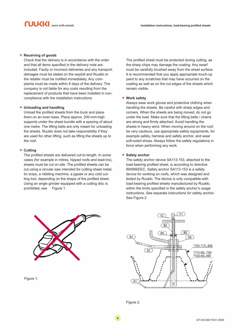
• Safety anchorThe safety anchor device SA113-153, attached to the load-bearing profiled sheet, is according to directive 89/689/EEC. Safety anchor SA113-153 is a safety device for working on roofs, which was designed and tested by Ruukki. The device is only compatible with load-bearing profiled sheets manufactured by Ruukki, within the limits specified in the safety anchor’s usage instructions. See separate instructions for safety anchor. See Figure 2
• Receiving of goodsCheck that the delivery is in accordance with the order and that all items specified in the delivery note are included. Faulty or incorrect deliveries and any transport damages must be stated on the waybill and Ruukki or the retailer must be notified immediately. Any com-plaints must be made within 8 days of the delivery. The company is not liable for any costs resulting from the replacement of products that have been installed in non-compliance with the installation instructions.
• Unloading and handlingUnload the profiled sheets from the truck and place them on an even base. Place approx. 200-mm-high supports under the sheet bundle with a spacing of about one metre. The lifting belts are only meant for unloading the sheets. Ruukki does not take responsibility if they are used for other lifting, such as lifting the sheets up to the roof.
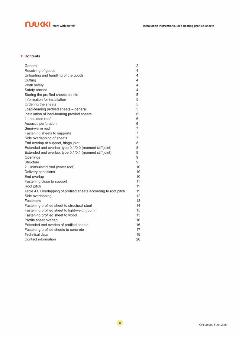
• CuttingThe profiled sheets are delivered cut-to-length. In some cases (for example in mitres, hipped roofs and lead-ins), sheets must be cut on site. The profiled sheets can be cut using a circular saw intended for cutting sheet metal, tin snips, a nibbling machine, a jigsaw or any cold cut-ting tool, depending on the shape of the profiled sheet. Using an angle grinder equipped with a cutting disc is prohibited, see Figure 1.
Figure 2.
Figure 1.
44
Installation instructions, load-bearing profiled sheets
CFI 00.000 FI/01.2009
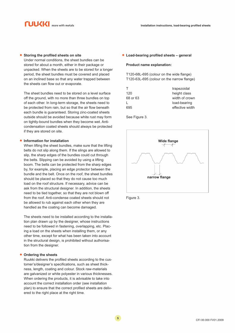
• Load-bearing profiled sheets – general
Product name explanation:
T120-68L-695 (colour on the wide flange)T120-63L-695 (colour on the narrow flange)
T trapezoidal120 height class68 or 63 width of crownL load-bearing695 effective width
See Figure 3.
• Storing the profiled sheets on siteUnder normal conditions, the sheet bundles can be stored for about a month, either in their package or unpacked. When the sheets are to be stored for a longer period, the sheet bundles must be covered and placed on an inclined base so that any water trapped between the sheets can flow out or evaporate.
The sheet bundles need to be stored on a level surface off the ground, with no more than three bundles on top of each other. In long-term storage, the sheets need to be protected from rain, but so that the air flow beneath each bundle is guaranteed. Storing zinc-coated sheets outside should be avoided because white rust may form on tightly-bound bundles when they become wet. Anti-condensation coated sheets should always be protected if they are stored on site.
• Information for installationWhen lifting the sheet bundles, make sure that the lifting belts do not slip along them. If the slings are allowed to slip, the sharp edges of the bundles could cut through the belts. Slipping can be avoided by using a lifting boom. The belts can be protected from the sharp edges by, for example, placing an edge protector between the bundle and the belt. Once on the roof, the sheet bundles should be placed so that they do not cause too much load on the roof structure. If necessary, advice can be ask from the structural designer. In addition, the sheets need to be tied together, so that they are not blown off from the roof. Anti-condense coated sheets should not be allowed to rub against each other when they are handled as the coating can become damaged.
The sheets need to be installed according to the installa-tion plan drawn up by the designer, whose instructions need to be followed in fastening, overlapping, etc. Plac-ing a load on the sheets when installing them, or any other time, except for what has been taken into account in the structural design, is prohibited without authorisa-tion from the designer.
• Ordering the sheetsRuukki delivers the profiled sheets according to the cus-tomer’s/designer’s specifications, such as sheet thick-ness, length, coating and colour. Stock raw-materials are galvanized or white polyester in various thicknesses. When ordering the products, it is advisable to take into account the correct installation order (see installation plan) to ensure that the correct profiled sheets are deliv-ered to the right place at the right time.
Figure 3.
Wide flange
narrow flange
55
Installation instructions, load-bearing profiled sheets
CFI 00.000 FI/01.2009
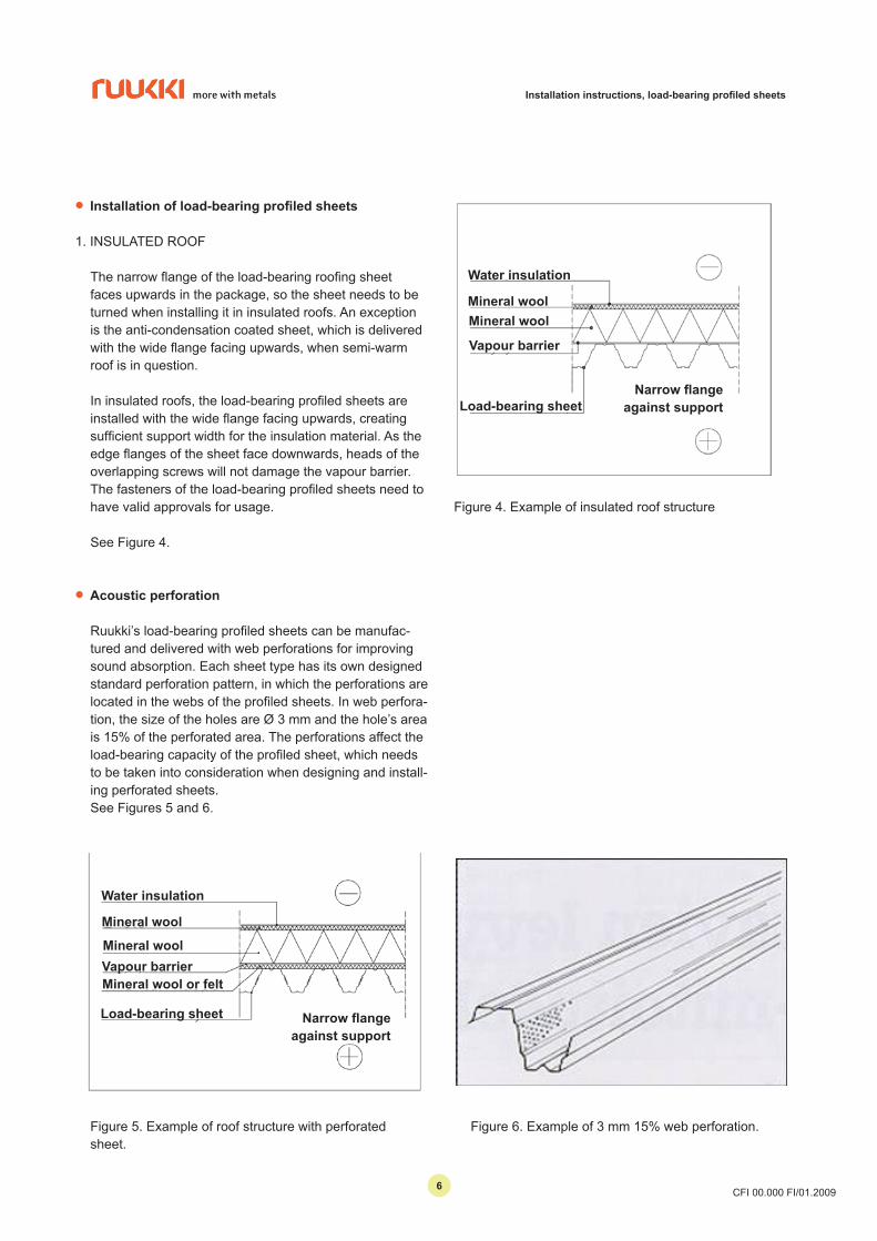
• Installation of load-bearing profiled sheets
1. INSULATED ROOF
The narrow flange of the load-bearing roofing sheet faces upwards in the package, so the sheet needs to be turned when installing it in insulated roofs. An exception is the anti-condensation coated sheet, which is delivered with the wide flange facing upwards, when semi-warm roof is in question.
In insulated roofs, the load-bearing profiled sheets are installed with the wide flange facing upwards, creating sufficient support width for the insulation material. As the edge flanges of the sheet face downwards, heads of the overlapping screws will not damage the vapour barrier. The fasteners of the load-bearing profiled sheets need to have valid approvals for usage.
See Figure 4.
Figure 4. Example of insulated roof structure
• Acoustic perforation
Ruukki’s load-bearing profiled sheets can be manufac-tured and delivered with web perforations for improving sound absorption. Each sheet type has its own designed standard perforation pattern, in which the perforations are located in the webs of the profiled sheets. In web perfora-tion, the size of the holes are Ø 3 mm and the hole’s area is 15% of the perforated area. The perforations affect the load-bearing capacity of the profiled sheet, which needs to be taken into consideration when designing and install-ing perforated sheets.See Figures 5 and 6.
Figure 5. Example of roof structure with perforated sheet.
Figure 6. Example of 3 mm 15% web perforation.
Water insulation
Mineral wool
Vapour barrier
Load-bearing sheet
Mineral wool
Narrow flange against support
Narrow flange against support
Water insulation
Mineral wool
Mineral woolVapour barrierMineral wool or felt
Load-bearing sheet
66
Installation instructions, load-bearing profiled sheets
CFI 00.000 FI/01.2009
Figure 9.
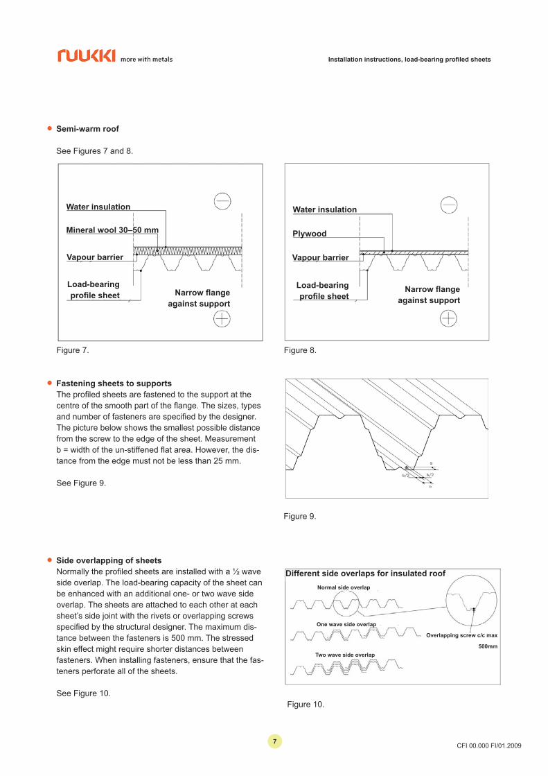
• Fastening sheets to supportsThe profiled sheets are fastened to the support at the centre of the smooth part of the flange. The sizes, types and number of fasteners are specified by the designer. The picture below shows the smallest possible distance from the screw to the edge of the sheet. Measurement b = width of the un-stiffened flat area. However, the dis-tance from the edge must not be less than 25 mm.
See Figure 9.
• Semi-warm roof See Figures 7 and 8.
Figure 7.
• Side overlapping of sheetsNormally the profiled sheets are installed with a ½ wave side overlap. The load-bearing capacity of the sheet can be enhanced with an additional one- or two wave side overlap. The sheets are attached to each other at each sheet’s side joint with the rivets or overlapping screws specified by the structural designer. The maximum dis-tance between the fasteners is 500 mm. The stressed skin effect might require shorter distances between fasteners. When installing fasteners, ensure that the fas-teners perforate all of the sheets.
See Figure 10.Figure 10.
Figure 8.
Water insulation
Mineral wool 30–50 mm
Vapour barrier
Load-bearing profile sheet Narrow flange
against support
Water insulation
Plywood
Vapour barrier
Load-bearing profile sheet
Narrow flange against support
Different side overlaps for insulated roofNormal side overlap
One wave side overlap
Two wave side overlap
Overlapping screw c/c max
500mm
77
Installation instructions, load-bearing profiled sheets
CFI 00.000 FI/01.2009
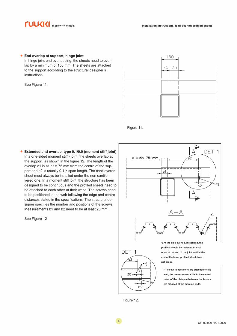
• End overlap at support, hinge jointIn hinge joint end overlapping, the sheets need to over-lap by a minimum of 150 mm. The sheets are attached to the support according to the structural designer’s instructions.
See Figure 11.
• Extended end overlap, type 0.1/0.0 (moment stiff joint)In a one-sided moment stiff - joint, the sheets overlap at the support, as shown in the figure 12. The length of the overlap e1 is at least 75 mm from the centre of the sup-port and e2 is usually 0.1 × span length. The cantilevered sheet must always be installed under the non cantile-vered one. In a moment stiff joint, the structure has been designed to be continuous and the profiled sheets need to be attached to each other at their webs. The screws need to be positioned in the web following the edge and centre distances stated in the specifications. The structural de-signer specifies the number and positions of the screws. Measurements b1 and b2 need to be at least 25 mm. See Figure 12
Figure 11.
Kuva 12.
Figure 12.
*) At the side overlap, if required, the
profiles should be fastened to each
other at the end of the joint so that the
end of the lower profiled sheet does
not droop.
**) If several fasteners are attached to the
web, the measurement e2 is to the central
point of the distance between the fasten-
ers situated at the extreme ends.
88
Installation instructions, load-bearing profiled sheets
CFI 00.000 FI/01.2009
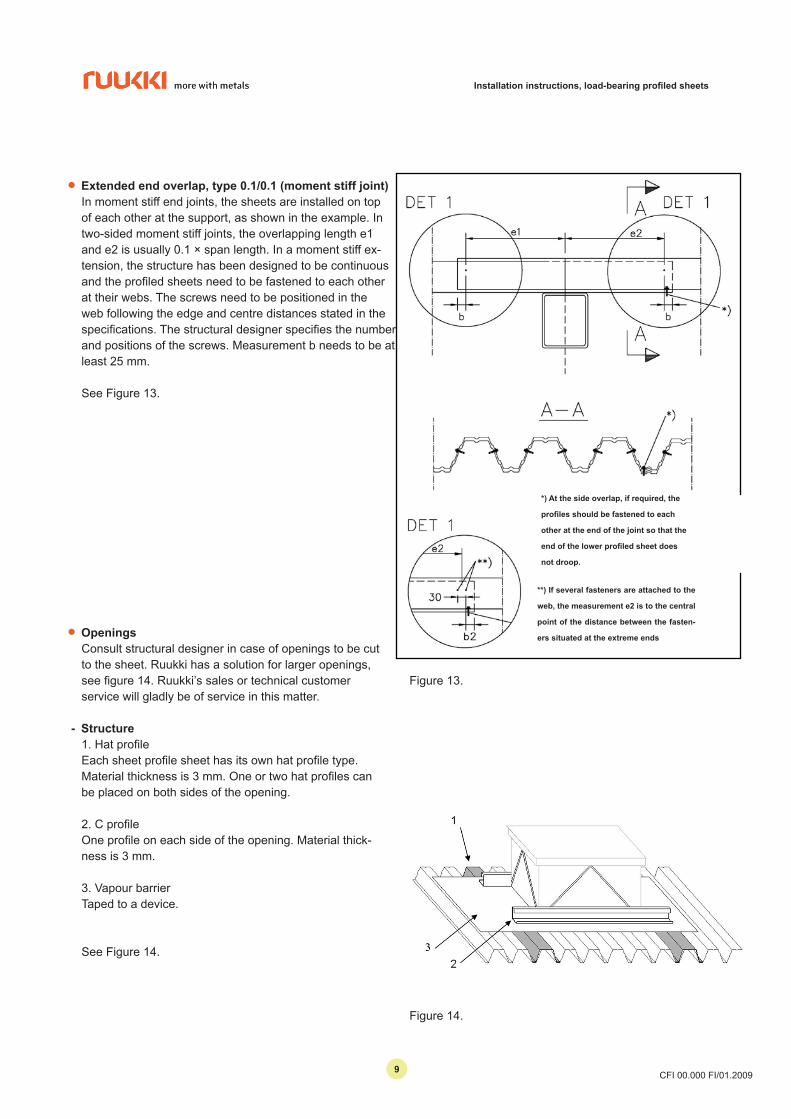
• Extended end overlap, type 0.1/0.1 (moment stiff joint)In moment stiff end joints, the sheets are installed on top of each other at the support, as shown in the example. In two-sided moment stiff joints, the overlapping length e1 and e2 is usually 0.1 × span length. In a moment stiff ex-tension, the structure has been designed to be continuous and the profiled sheets need to be fastened to each other at their webs. The screws need to be positioned in the web following the edge and centre distances stated in the specifications. The structural designer specifies the number and positions of the screws. Measurement b needs to be at least 25 mm.
See Figure 13.
Figure 13.
• OpeningsConsult structural designer in case of openings to be cut to the sheet. Ruukki has a solution for larger openings, see figure 14. Ruukki’s sales or technical customer service will gladly be of service in this matter.
- Structure1. Hat profileEach sheet profile sheet has its own hat profile type.Material thickness is 3 mm. One or two hat profiles can be placed on both sides of the opening.
2. C profileOne profile on each side of the opening. Material thick-ness is 3 mm.
3. Vapour barrierTaped to a device.
See Figure 14.
Figure 14.
*) At the side overlap, if required, the
profiles should be fastened to each
other at the end of the joint so that the
end of the lower profiled sheet does
not droop.
**) If several fasteners are attached to the
web, the measurement e2 is to the central
point of the distance between the fasten-
ers situated at the extreme ends
99
Installation instructions, load-bearing profiled sheets
CFI 00.000 FI/01.2009
2. UNINSULATED ROOF (WATER ROOF)
• Delivery conditions
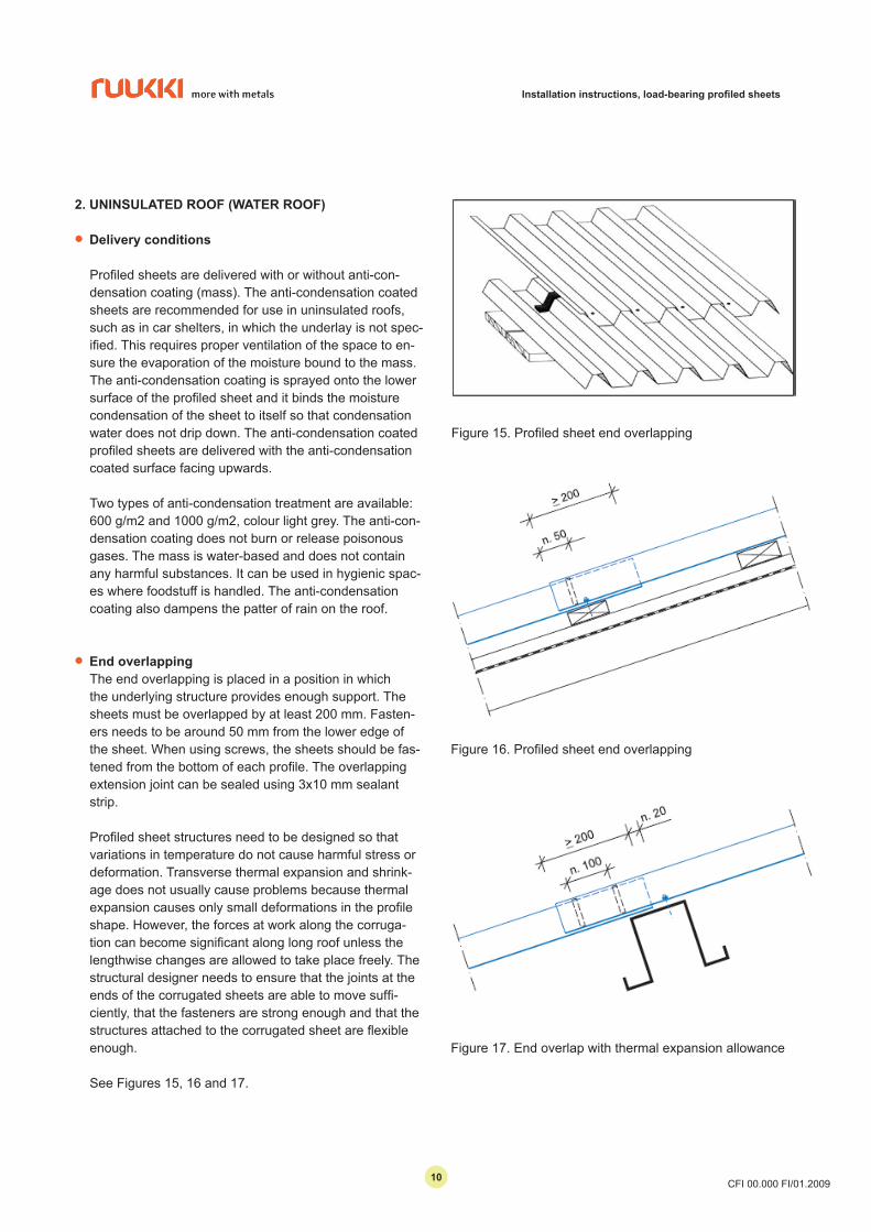
Profiled sheets are delivered with or without anti-con-densation coating (mass). The anti-condensation coated sheets are recommended for use in uninsulated roofs, such as in car shelters, in which the underlay is not spec-ified. This requires proper ventilation of the space to en-sure the evaporation of the moisture bound to the mass. The anti-condensation coating is sprayed onto the lower surface of the profiled sheet and it binds the moisture condensation of the sheet to itself so that condensation water does not drip down. The anti-condensation coated profiled sheets are delivered with the anti-condensation coated surface facing upwards.
Two types of anti-condensation treatment are available: 600 g/m2 and 1000 g/m2, colour light grey. The anti-con-densation coating does not burn or release poisonous gases. The mass is water-based and does not contain any harmful substances. It can be used in hygienic spac-es where foodstuff is handled. The anti-condensation coating also dampens the patter of rain on the roof.
• End overlappingThe end overlapping is placed in a position in which the underlying structure provides enough support. The sheets must be overlapped by at least 200 mm. Fasten-ers needs to be around 50 mm from the lower edge of the sheet. When using screws, the sheets should be fas-tened from the bottom of each profile. The overlapping extension joint can be sealed using 3x10 mm sealant strip.
Profiled sheet structures need to be designed so that variations in temperature do not cause harmful stress or deformation. Transverse thermal expansion and shrink-age does not usually cause problems because thermal expansion causes only small deformations in the profile shape. However, the forces at work along the corruga-tion can become significant along long roof unless the lengthwise changes are allowed to take place freely. The structural designer needs to ensure that the joints at the ends of the corrugated sheets are able to move suffi-ciently, that the fasteners are strong enough and that the structures attached to the corrugated sheet are flexible enough.
See Figures 15, 16 and 17.
Figure 15. Profiled sheet end overlapping
Figure 16. Profiled sheet end overlapping
Figure 17. End overlap with thermal expansion allowance
1010
Installation instructions, load-bearing profiled sheets
CFI 00.000 FI/01.2009
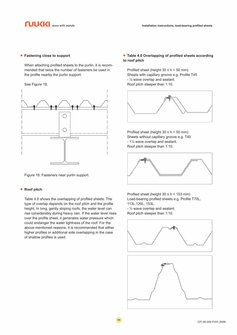
• Fastening close to support
When attaching profiled sheets to the purlin, it is recom-mended that twice the number of fasteners be used in the profile nearby the purlin support.
See Figure 18.
Figure 18. Fasteners near purlin support
• Roof pitch
Table 4.0 shows the overlapping of profiled sheets. The type of overlap depends on the roof pitch and the profile height. In long, gently sloping roofs, the water level can rise considerably during heavy rain. If the water level rises over the profile sheet, it generates water pressure which could endanger the water tightness of the roof. For the above-mentioned reasons, it is recommended that either higher profiles or additional side overlapping in the case of shallow profiles is used.
• Table 4.0 Overlapping of profiled sheets according to roof pitch
Profiled sheet (height 30 ≤ h < 50 mm)Sheets with capillary groove e.g. Profile T45- ½ wave overlap and sealant.Roof pitch steeper than 1:10.
Profiled sheet (height 30 ≤ h < 50 mm)Sheets without capillary groove e.g. T45- 1½ wave overlap and sealant.Roof pitch steeper than 1:10.
Profiled sheet (height 30 ≤ h < 153 mm)Load-bearing profiled sheets e.g. Profile T70L, 113L,120L, 153L.- ½ wave overlap and sealant.Roof pitch steeper than 1:10.
1111
Installation instructions, load-bearing profiled sheets
CFI 00.000 FI/01.2009
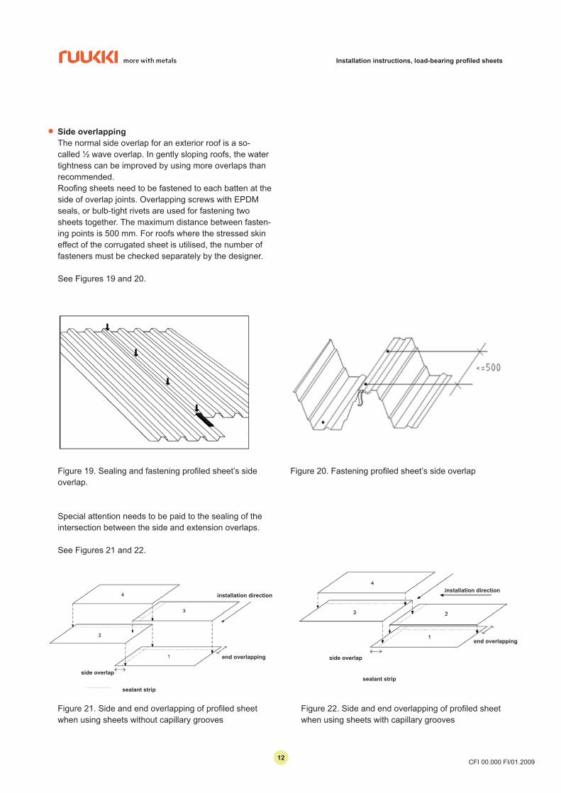
• Side overlappingThe normal side overlap for an exterior roof is a so-called ½ wave overlap. In gently sloping roofs, the water tightness can be improved by using more overlaps than recommended.Roofing sheets need to be fastened to each batten at the side of overlap joints. Overlapping screws with EPDM seals, or bulb-tight rivets are used for fastening two sheets together. The maximum distance between fasten-ing points is 500 mm. For roofs where the stressed skin effect of the corrugated sheet is utilised, the number of fasteners must be checked separately by the designer.
See Figures 19 and 20.
Figure 19. Sealing and fastening profiled sheet’s side overlap.
Figure 20. Fastening profiled sheet’s side overlap
Figure 21. Side and end overlapping of profiled sheet when using sheets without capillary grooves
Figure 22. Side and end overlapping of profiled sheet when using sheets with capillary grooves
Special attention needs to be paid to the sealing of the intersection between the side and extension overlaps.
See Figures 21 and 22.
installation direction
side overlap
end overlapping
sealant strip
installation direction
end overlapping
side overlap
sealant strip
1212
Installation instructions, load-bearing profiled sheets
CFI 00.000 FI/01.2009
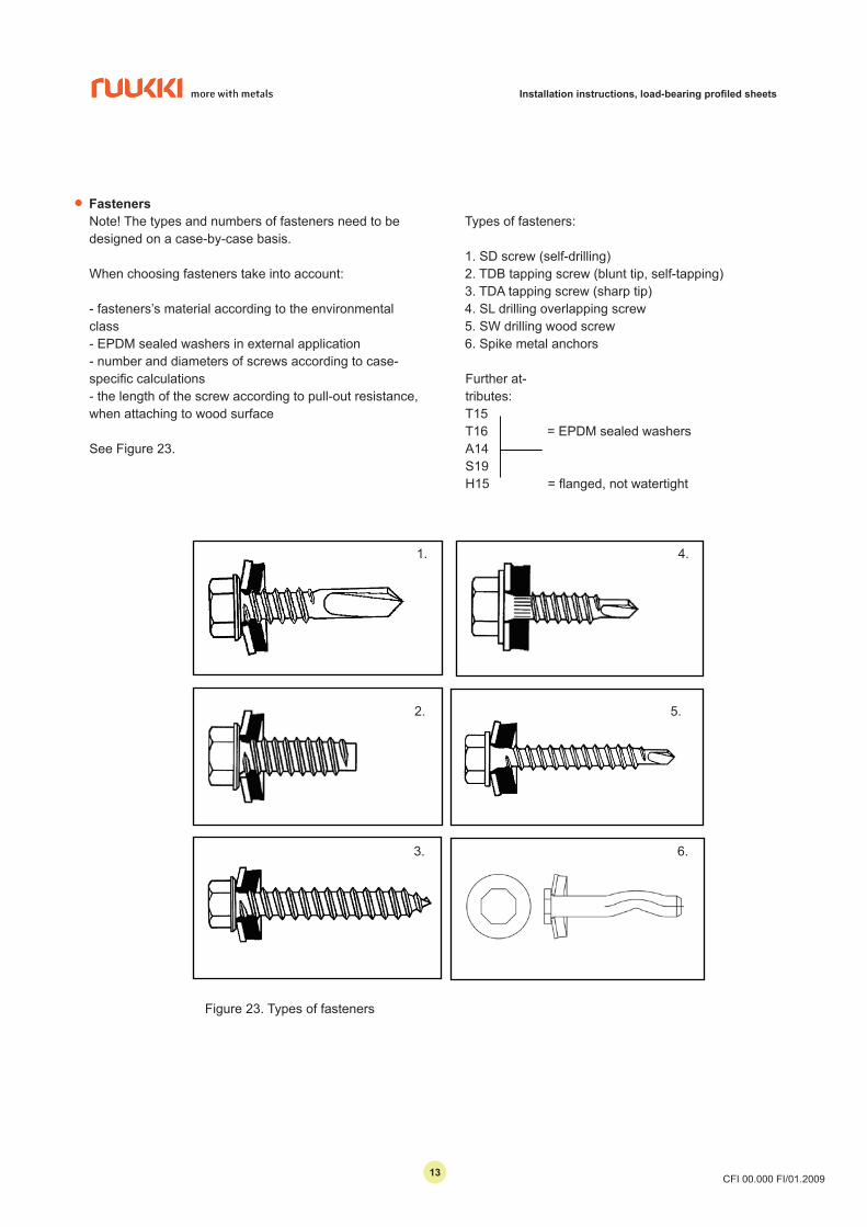
• FastenersNote! The types and numbers of fasteners need to be designed on a case-by-case basis.
When choosing fasteners take into account:
- fasteners’s material according to the environmental class- EPDM sealed washers in external application- number and diameters of screws according to case- specific calculations- the length of the screw according to pull-out resistance, when attaching to wood surface
See Figure 23.
Further at-tributes:T15T16A14S19H15
= EPDM sealed washers
= flanged, not watertight
Types of fasteners:
1. SD screw (self-drilling)2. TDB tapping screw (blunt tip, self-tapping)3. TDA tapping screw (sharp tip)4. SL drilling overlapping screw5. SW drilling wood screw6. Spike metal anchors
4.
5.
6.
1.
2.
3.
Figure 23. Types of fasteners
1313
Installation instructions, load-bearing profiled sheets
CFI 00.000 FI/01.2009
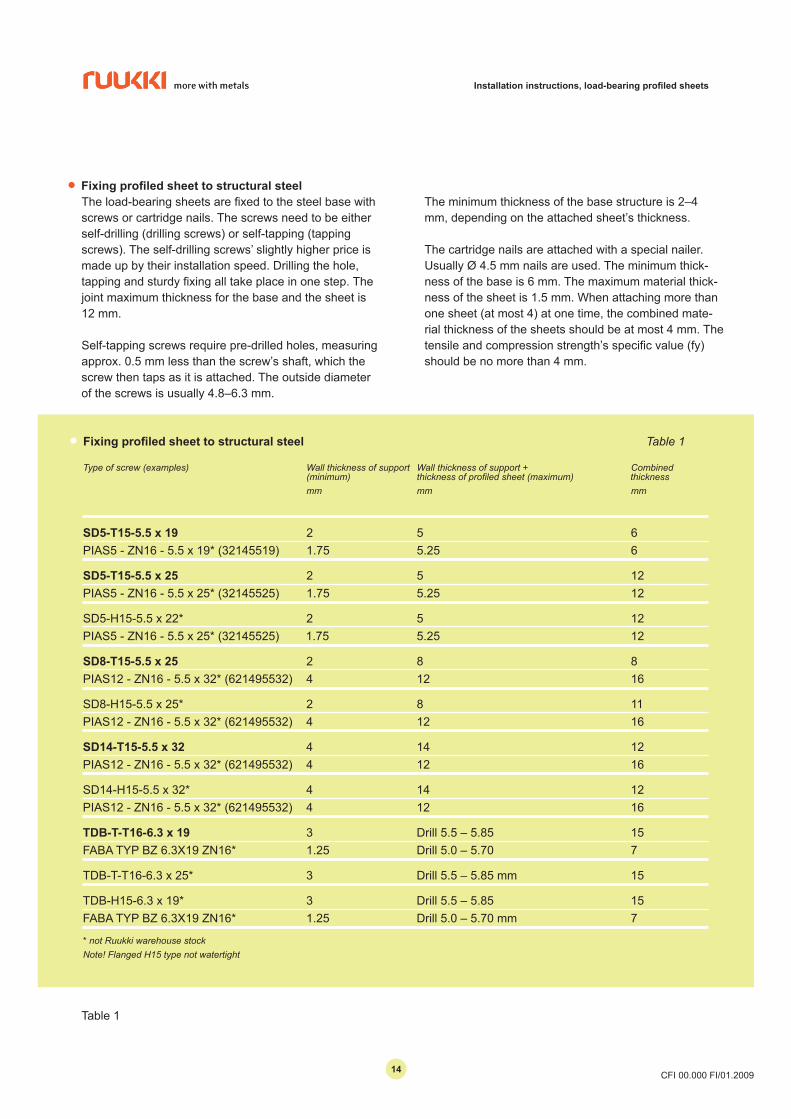
• Fixing profiled sheet to structural steel Table 1
Type of screw (examples) Wall thickness of support Wall thickness of support + Combined (minimum) thicknessofprofiledsheet(maximum)thickness mm mm mm
SD5-T15-5.5 x 19 2 5 6PIAS5 - ZN16 - 5.5 x 19* (32145519) 1.75 5.25 6
SD5-T15-5.5 x 25 2 5 12PIAS5 - ZN16 - 5.5 x 25* (32145525) 1.75 5.25 12
SD5-H15-5.5 x 22* 2 5 12 PIAS5 - ZN16 - 5.5 x 25* (32145525) 1.75 5.25 12
SD8-T15-5.5 x 25 2 8 8 PIAS12 - ZN16 - 5.5 x 32* (621495532) 4 12 16
SD8-H15-5.5 x 25* 2 8 11PIAS12 - ZN16 - 5.5 x 32* (621495532) 4 12 16
SD14-T15-5.5 x 32 4 14 12 PIAS12 - ZN16 - 5.5 x 32* (621495532) 4 12 16
SD14-H15-5.5 x 32* 4 14 12 PIAS12 - ZN16 - 5.5 x 32* (621495532) 4 12 16
TDB-T-T16-6.3 x 19 3 Drill 5.5 – 5.85 15FABA TYP BZ 6.3X19 ZN16* 1.25 Drill 5.0 – 5.70 7
TDB-T-T16-6.3 x 25* 3 Drill 5.5 – 5.85 mm 15
TDB-H15-6.3 x 19* 3 Drill 5.5 – 5.85 15FABA TYP BZ 6.3X19 ZN16* 1.25 Drill 5.0 – 5.70 mm 7
* not Ruukki warehouse stockNote! Flanged H15 type not watertight
• Fixing profiled sheet to structural steelThe load-bearing sheets are fixed to the steel base with screws or cartridge nails. The screws need to be either self-drilling (drilling screws) or self-tapping (tapping screws). The self-drilling screws’ slightly higher price is made up by their installation speed. Drilling the hole, tapping and sturdy fixing all take place in one step. The joint maximum thickness for the base and the sheet is 12 mm.
Self-tapping screws require pre-drilled holes, measuring approx. 0.5 mm less than the screw’s shaft, which the screw then taps as it is attached. The outside diameter of the screws is usually 4.8–6.3 mm.
The minimum thickness of the base structure is 2–4 mm, depending on the attached sheet’s thickness.
The cartridge nails are attached with a special nailer. Usually Ø 4.5 mm nails are used. The minimum thick-ness of the base is 6 mm. The maximum material thick-ness of the sheet is 1.5 mm. When attaching more than one sheet (at most 4) at one time, the combined mate-rial thickness of the sheets should be at most 4 mm. The tensile and compression strength’s specific value (fy) should be no more than 4 mm.
Table 1
1414
Installation instructions, load-bearing profiled sheets
CFI 00.000 FI/01.2009
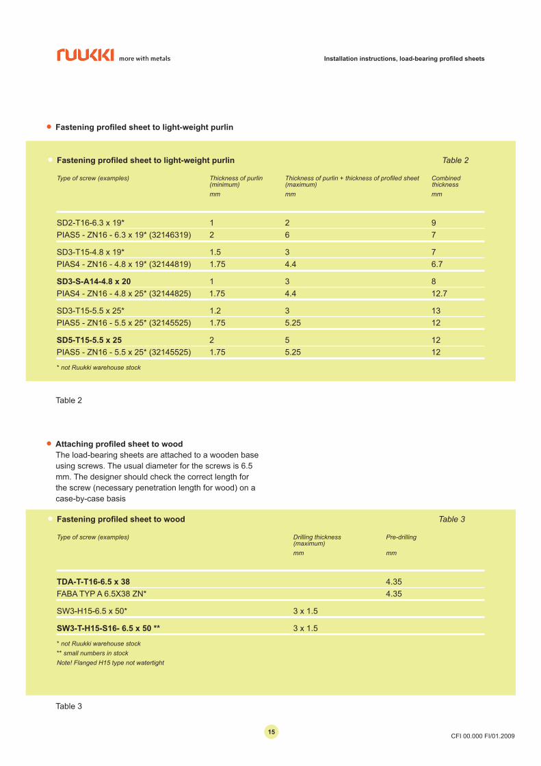
• Fastening profiled sheet to light-weight purlin Table 2
Typeofscrew(examples) Thicknessofpurlin Thicknessofpurlin+thicknessofprofiledsheet Combined (minimum) (maximum) thickness mm mm mm
SD2-T16-6.3 x 19* 1 2 9PIAS5 - ZN16 - 6.3 x 19* (32146319) 2 6 7
SD3-T15-4.8 x 19* 1.5 3 7PIAS4 - ZN16 - 4.8 x 19* (32144819) 1.75 4.4 6.7
SD3-S-A14-4.8 x 20 1 3 8 PIAS4 - ZN16 - 4.8 x 25* (32144825) 1.75 4.4 12.7
SD3-T15-5.5 x 25* 1.2 3 13 PIAS5 - ZN16 - 5.5 x 25* (32145525) 1.75 5.25 12
SD5-T15-5.5 x 25 2 5 12PIAS5 - ZN16 - 5.5 x 25* (32145525) 1.75 5.25 12
* not Ruukki warehouse stock
• Fastening profiled sheet to light-weight purlin
• Attaching profiled sheet to woodThe load-bearing sheets are attached to a wooden base using screws. The usual diameter for the screws is 6.5 mm. The designer should check the correct length for the screw (necessary penetration length for wood) on a case-by-case basis
• Fastening profiled sheet to wood Table 3
Type of screw (examples) Drilling thickness Pre-drilling (maximum) mm mm
TDA-T-T16-6.5 x 38 4.35 FABA TYP A 6.5X38 ZN* 4.35
SW3-H15-6.5 x 50* 3 x 1.5
SW3-T-H15-S16- 6.5 x 50 ** 3 x 1.5
* not Ruukki warehouse stock** small numbers in stockNote! Flanged H15 type not watertight
Table 2
Table 3
1515
Installation instructions, load-bearing profiled sheets
CFI 00.000 FI/01.2009
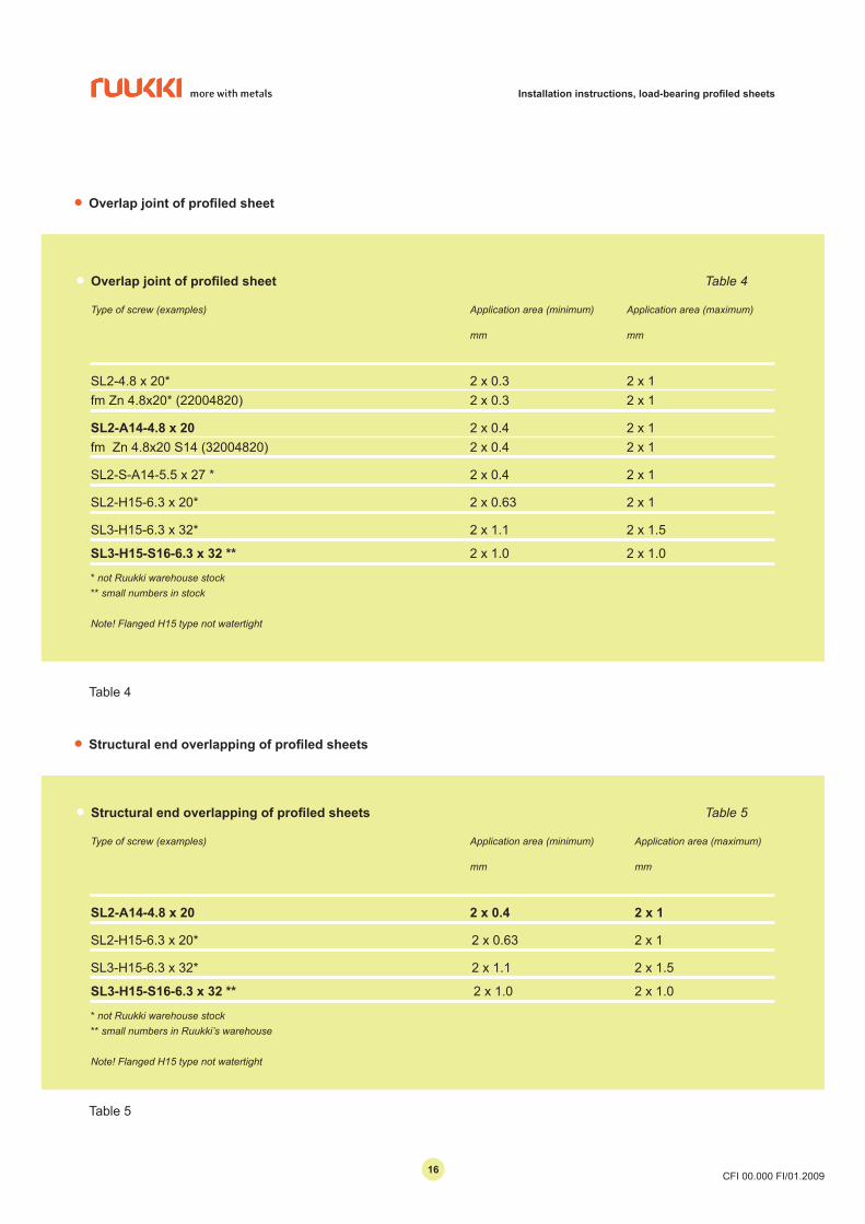
• Overlap joint of profiled sheet
• Overlap joint of profiled sheet Table 4
Type of screw (examples) Application area (minimum) Application area (maximum) mm mm
SL2-4.8 x 20* 2 x 0.3 2 x 1 fm Zn 4.8x20* (22004820) 2 x 0.3 2 x 1
SL2-A14-4.8 x 20 2 x 0.4 2 x 1fm Zn 4.8x20 S14 (32004820) 2 x 0.4 2 x 1
SL2-S-A14-5.5 x 27 * 2 x 0.4 2 x 1
SL2-H15-6.3 x 20* 2 x 0.63 2 x 1
SL3-H15-6.3 x 32* 2 x 1.1 2 x 1.5
SL3-H15-S16-6.3 x 32 ** 2 x 1.0 2 x 1.0
* not Ruukki warehouse stock** small numbers in stock
Note! Flanged H15 type not watertight
Table 4
• Structural end overlapping of profiled sheets
• Structural end overlapping of profiled sheets Table 5
Type of screw (examples) Application area (minimum) Application area (maximum) mm mm
SL2-A14-4.8 x 20 2 x 0.4 2 x 1
SL2-H15-6.3 x 20* 2 x 0.63 2 x 1
SL3-H15-6.3 x 32* 2 x 1.1 2 x 1.5
SL3-H15-S16-6.3 x 32 ** 2 x 1.0 2 x 1.0
* not Ruukki warehouse stock** small numbers in Ruukki’s warehouse
Note! Flanged H15 type not watertight
Table 5
1616
Installation instructions, load-bearing profiled sheets
CFI 00.000 FI/01.2009
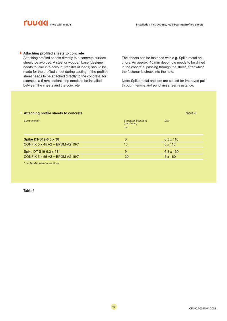
• Attaching profile sheets to concrete Table 6
Spike anchor Structural thickness Drill (maximum) mm
Spike DT-S19-6.3 x 38 6 6.3 x 110CONFIX 5 x 45 A2 + EPDM-A2 19/7 10 5 x 110
Spike DT-S19-6.3 x 51* 9 6.3 x 160CONFIX 5 x 55 A2 + EPDM-A2 19/7 20 5 x 160
* not Ruukki warehouse stock
Table 6
• Attaching profiled sheets to concreteAttaching profiled sheets directly to a concrete surface should be avoided. A steel or wooden base (designer needs to take into account transfer of loads) should be made for the profiled sheet during casting. If the profiled sheet needs to be attached directly to the concrete, for example, a 5 mm sealant strip needs to be installed between the sheets and the concrete.
The sheets can be fastened with e.g. Spike metal an-chors. An approx. 45 mm deep hole needs to be drilled in the concrete, passing through the sheet, after which the fastener is struck into the hole.
Note: Spike metal anchors are sealed for improved pull-through, tensile and punching sheer resistance.
1717
Installation instructions, load-bearing profiled sheets
CFI 00.000 FI/01.2009
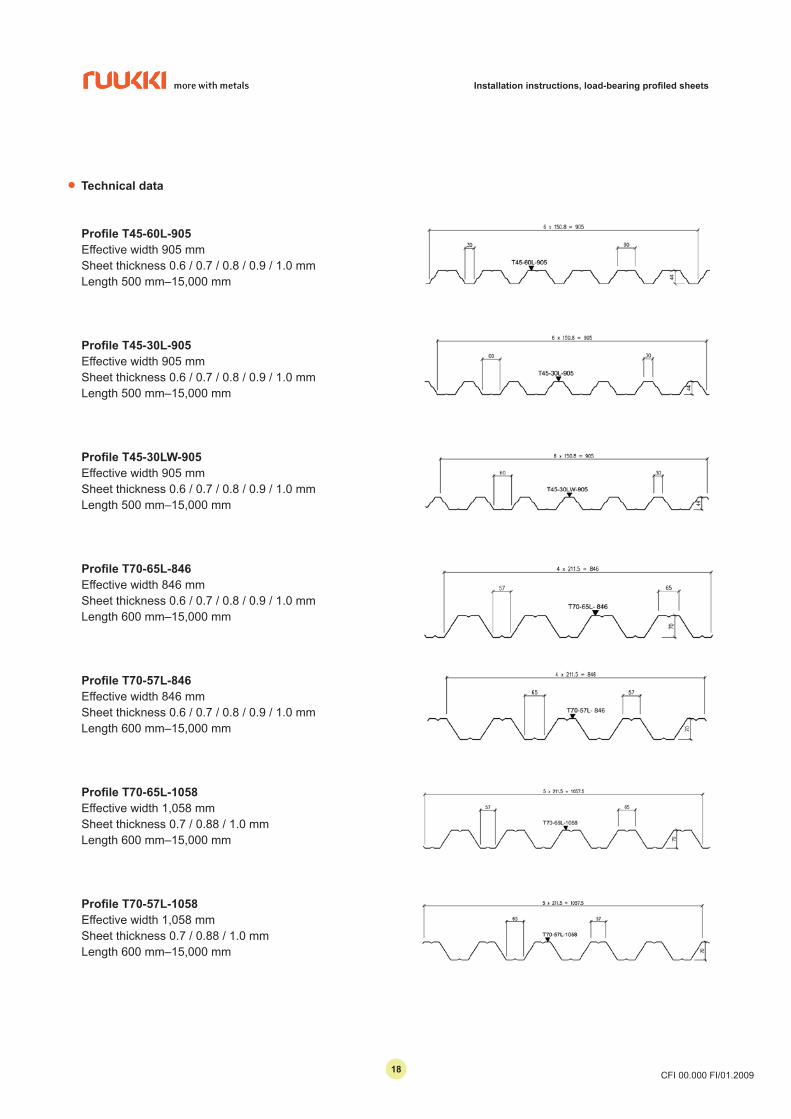
• Technical data
Profile T45-60L-905Effective width 905 mmSheet thickness 0.6 / 0.7 / 0.8 / 0.9 / 1.0 mmLength 500 mm–15,000 mm
Profile T45-30L-905Effective width 905 mmSheet thickness 0.6 / 0.7 / 0.8 / 0.9 / 1.0 mmLength 500 mm–15,000 mm
Profile T45-30LW-905Effective width 905 mmSheet thickness 0.6 / 0.7 / 0.8 / 0.9 / 1.0 mmLength 500 mm–15,000 mm
Profile T70-65L-846Effective width 846 mmSheet thickness 0.6 / 0.7 / 0.8 / 0.9 / 1.0 mmLength 600 mm–15,000 mm
Profile T70-57L-846Effective width 846 mmSheet thickness 0.6 / 0.7 / 0.8 / 0.9 / 1.0 mmLength 600 mm–15,000 mm
Profile T70-65L-1058Effective width 1,058 mmSheet thickness 0.7 / 0.88 / 1.0 mmLength 600 mm–15,000 mm
Profile T70-57L-1058Effective width 1,058 mmSheet thickness 0.7 / 0.88 / 1.0 mmLength 600 mm–15,000 mm
1818
Installation instructions, load-bearing profiled sheets
CFI 00.000 FI/01.2009
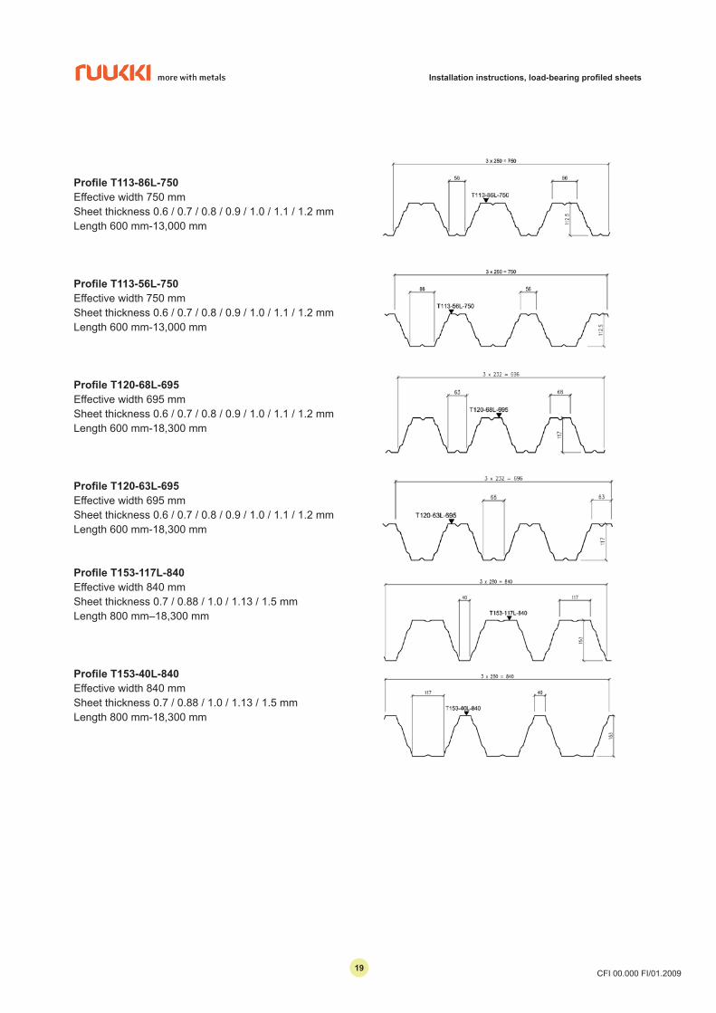
Profile T113-86L-750Effective width 750 mmSheet thickness 0.6 / 0.7 / 0.8 / 0.9 / 1.0 / 1.1 / 1.2 mmLength 600 mm-13,000 mm
Profile T113-56L-750Effective width 750 mmSheet thickness 0.6 / 0.7 / 0.8 / 0.9 / 1.0 / 1.1 / 1.2 mmLength 600 mm-13,000 mm
Profile T120-68L-695Effective width 695 mmSheet thickness 0.6 / 0.7 / 0.8 / 0.9 / 1.0 / 1.1 / 1.2 mmLength 600 mm-18,300 mm
Profile T120-63L-695Effective width 695 mmSheet thickness 0.6 / 0.7 / 0.8 / 0.9 / 1.0 / 1.1 / 1.2 mmLength 600 mm-18,300 mm
Profile T153-117L-840Effective width 840 mmSheet thickness 0.7 / 0.88 / 1.0 / 1.13 / 1.5 mmLength 800 mm–18,300 mm
Profile T153-40L-840Effective width 840 mmSheet thickness 0.7 / 0.88 / 1.0 / 1.13 / 1.5 mmLength 800 mm-18,300 mm
1919
Installation instructions, load-bearing profiled sheets
CFI 00.000 FI/01.2009
This data sheet is accurate to the best of our knowledge and understanding. Although every effort has been made to ensure accuracy, the company cannot accept responsibility for any loss, damage or other consequences resulting
from incorrect application of the information. We reserve the right to make changes.
Copyright © 2009 Rautaruukki Corporation. All rights reserved.Ruukki, Rautaruukki, More With Metals and the names of Ruukki’s products are trademarks or registered trademarks of Rautaruukki Corporation.
• Contact information
Technical customer service (for further information) tel. +358 20 59 127 fax +358 20 592 7700 Installation service tel. +358 20 59 127 fax +358 20 592 7878
Rautaruukki Corporation www.ruukki.com
• Receiving of goods
- Check that the delivery is in accordance with the order and that all items specified in the delivery note are included.- Faulty or incorrect deliveries and any transport damages must be stated on the waybill and Ruukki or the retailer must be notified immediately.- Any complaints must be made within 8 days of the delivery- Possible lifting belts delivered with the goods, are only for unloading the goods.- Follow always safety regulations in force when performing any work.
2020