rucksack enhanced portable power … user...2 introduction purpose: the rucksack enhanced portable...
TRANSCRIPT
RUCKSACK ENHANCED
PORTABLE POWER SYSTEM
USER GUIDE
Manufactured for the U.S. Army CECOM LCMC, Ft. Monmouth, N.J.
850042 Rev A

1
REPPS User Guide
Table of Contents Introduction............................................................................................................................... 2
Purpose:............................................................................................................................. 2 Technical Specifications ................................................................................................... 3
System Components.................................................................................................................. 4 Basics .................................................................................................................................... 4
Charge Controller (BTC-70824-1) ................................................................................... 4 Input Options ........................................................................................................................ 5
55 Watt Solar Panel (BTP-70824-T) ................................................................................ 5 AC / DC Adapter (591791-1) ........................................................................................... 5 NATO Slave Plug (393034-1) .......................................................................................... 6 x90 Scavenger (BTA-70768)............................................................................................ 6
Outputs.................................................................................................................................. 7 Charge Adapter (BTA-70782) .......................................................................................... 7 Pass-Thru Assembly (BTA-70781) .................................................................................. 7 Multi Chemistry Charger (BTC-70824-2) ........................................................................ 8
Accessories ........................................................................................................................... 9 8’ Extension (390651)....................................................................................................... 9 Female Cigarette Lighter (BTA-70769) ......................................................................... 10 Solar Shade (Part of BTP-70824-T) ............................................................................... 10 Camouflaged Bag (450437)............................................................................................ 11
Sample System Configurations............................................................................................... 11 Single Panel: Charging only ........................................................................................ 11 Single Panel: Pass-Thru Power to 12V Device............................................................ 12 Dual Panel: Pass-Thru Power to 12V or 24V Device................................................ 13 Single Panel with Additional Battery: 12V or 24V Device......................................... 14 AC Power: Charging Only......................................................................................... 14 AC Power: 12V Device ............................................................................................. 15
Basic Operation....................................................................................................................... 15 Charge Status LED Quick Reference ............................................................................. 16 Solid Red LED Trouble Shooting................................................................................... 17 Operation Under Extreme Environmental Conditions.................................................... 17
Maintenance............................................................................................................................ 18 Cleaning .......................................................................................................................... 18 Inspection........................................................................................................................ 18 Basic Functional Test...................................................................................................... 19 Simplified Operator Troubleshooting Procedures .......................................................... 20 Warranty / Repair Information........................................................................................ 20

2
Introduction Purpose: The Rucksack Enhanced Portable Power System (REPPS) is a state-of-the-art, lightweight, portable power system capable of recharging batteries and / or acting as a continuous power source. REPPS is intended for those users that require a lightweight and highly portable rechargeable battery system or a continuous power source. Special Operations Forces, Military Intelligence units, Ranger units, and Forward Observers are the intended users, but the system could be used by any war-fighter requiring this capability.

3
Technical Specifications
Dimensions Folded including 2 BB-2590/Us 12” (305 mm) x 12” (305 mm) x 5” (127 mm)
Deployed Solar Panel Dimensions 32” (813 mm) x 55” (1397 mm) x 0.5” (13 mm)
Weight 9.0 lbs Maximum
Color Solar Panel and Charge Controller Adapters and Cables Multi Chemistry Charger
Desert Tan (Camouflage) Black Black
Safety Features Primary Battery Charging Protection Short Circuit / Over Current Protection Under Voltage Protection Over Voltage Charging Protection
Operating Temperature Range -4°F (-20°C) to +122°F (+50°C)
Storage Temperature Range -40°F (-40°C) to +158°F (+70°C)
Input Power Requirements AC Operation
AC / DC Power Adapter DC Operation
AC / DC Power Adapter NATO Plug Adapter Solar Panel
100 – 230 VAC @ 50-60 Hz 11.75 V – 16.0 V 20 - 30 VDC 55 W
4
System Components
Basics
Charge Controller (BTC-70824-1)
Input
Power Flow Output
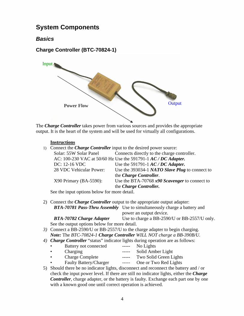
The Charge Controller takes power from various sources and provides the appropriate output. It is the heart of the system and will be used for virtually all configurations.
Instructions 1) Connect the Charge Controller input to the desired power source:
Solar: 55W Solar Panel Connects directly to the charge controller. AC: 100-230 VAC at 50/60 Hz Use the 591791-1 AC / DC Adapter. DC: 12-16 VDC Use the 591791-1 AC / DC Adapter. 28 VDC Vehicular Power: Use the 393034-1 NATO Slave Plug to connect to
the Charge Controller. X90 Primary (BA-5590): Use the BTA-70768 x90 Scavenger to connect to
the Charge Controller. See the input options below for more detail.
2) Connect the Charge Controller output to the appropriate output adapter:
BTA-70781 Pass-Thru Assembly Use to simultaneously charge a battery and power an output device.
BTA-70782 Charge Adapter Use to charge a BB-2590/U or BB-2557/U only. See the output options below for more detail.
3) Connect a BB-2590/U or BB-2557/U to the charge adapter to begin charging. Note: The BTC-70824-1 Charge Controller WILL NOT charge a BB-390B/U.
4) Charge Controller “status” indicator lights during operation are as follows: • Battery not connected ----- No Lights • Charging ----- Solid Amber Light • Charge Complete ----- Two Solid Green Lights • Faulty Battery/Charger ----- One or Two Red Lights
5) Should there be no indicator lights, disconnect and reconnect the battery and / or check the input power level. If there are still no indicator lights, either the Charge Controller, charge adapter, or the battery is faulty. Exchange each part one by one with a known good one until correct operation is achieved.
5
Input Options WARNING The Input Options include the BTP-70824-T Solar Panel, the 591791-1 AC / DC Adapter, the 393034-1 NATO Slave Plug, and the BTA-70768 x90 Scavenger. Under no circumstances should these ever be connected to each other!
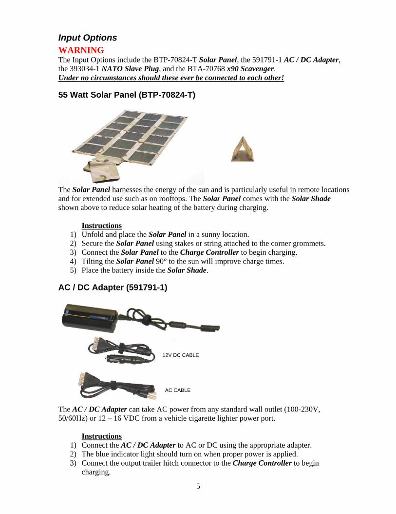
55 Watt Solar Panel (BTP-70824-T)
The Solar Panel harnesses the energy of the sun and is particularly useful in remote locations and for extended use such as on rooftops. The Solar Panel comes with the Solar Shade shown above to reduce solar heating of the battery during charging.
Instructions 1) Unfold and place the Solar Panel in a sunny location. 2) Secure the Solar Panel using stakes or string attached to the corner grommets. 3) Connect the Solar Panel to the Charge Controller to begin charging. 4) Tilting the Solar Panel 90° to the sun will improve charge times. 5) Place the battery inside the Solar Shade.
AC / DC Adapter (591791-1)
12V DC CABLE
AC CABLE
The AC / DC Adapter can take AC power from any standard wall outlet (100-230V, 50/60Hz) or 12 – 16 VDC from a vehicle cigarette lighter power port.
Instructions
1) Connect the AC / DC Adapter to AC or DC using the appropriate adapter. 2) The blue indicator light should turn on when proper power is applied. 3) Connect the output trailer hitch connector to the Charge Controller to begin
charging.

6
NATO Slave Plug (393034-1)
The NATO Slave Plug can take power from many standard military vehicles such as the HMWWV.
Instructions 1) Connect the NATO Slave Plug to the vehicle. 2) Connect the trailer hitch connector to the Charge Controller to begin charging. 3) Be sure to recharge the vehicle battery after 4 charges.
x90 Scavenger (BTA-70768)
The x90 Scavenger can take power from a partially discharged disposable x90 series battery.
Instructions 1) Connect a partially discharged BA-5590 to the x90 Scavenger securing with the
Velcro strap. 2) Connect the trailer hitch connector to the Charge Controller to begin charging. 3) Discard empty BA-5590 properly.
7
Outputs
Charge Adapter (BTA-70782)
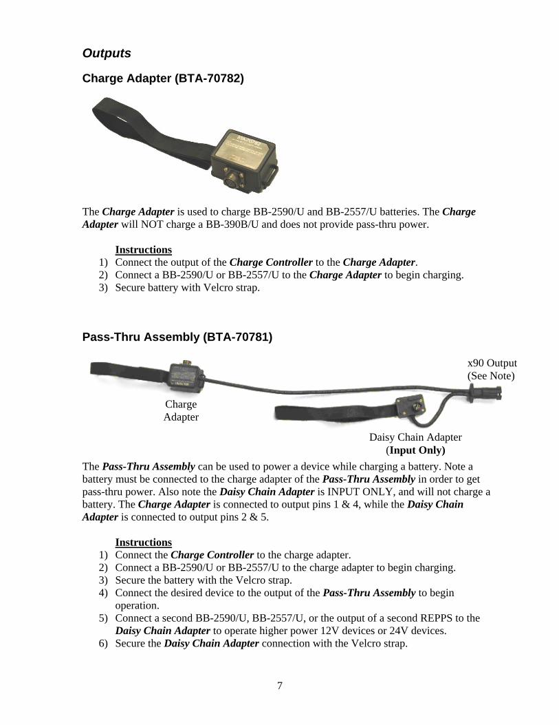
The Charge Adapter is used to charge BB-2590/U and BB-2557/U batteries. The Charge Adapter will NOT charge a BB-390B/U and does not provide pass-thru power.
Instructions 1) Connect the output of the Charge Controller to the Charge Adapter. 2) Connect a BB-2590/U or BB-2557/U to the Charge Adapter to begin charging. 3) Secure battery with Velcro strap.
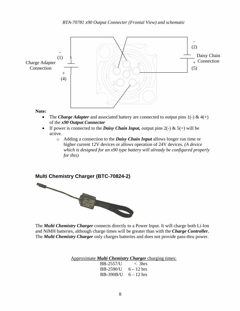
Pass-Thru Assembly (BTA-70781)
x90 Output (See Note)
Charge Adapter
Daisy Chain Adapter (Input Only)
The Pass-Thru Assembly can be used to power a device while charging a battery. Note a battery must be connected to the charge adapter of the Pass-Thru Assembly in order to get pass-thru power. Also note the Daisy Chain Adapter is INPUT ONLY, and will not charge a battery. The Charge Adapter is connected to output pins 1 & 4, while the Daisy Chain Adapter is connected to output pins 2 & 5.
Instructions
1) Connect the Charge Controller to the charge adapter. 2) Connect a BB-2590/U or BB-2557/U to the charge adapter to begin charging. 3) Secure the battery with the Velcro strap. 4) Connect the desired device to the output of the Pass-Thru Assembly to begin
operation. 5) Connect a second BB-2590/U, BB-2557/U, or the output of a second REPPS to the
Daisy Chain Adapter to operate higher power 12V devices or 24V devices. 6) Secure the Daisy Chain Adapter connection with the Velcro strap.
8
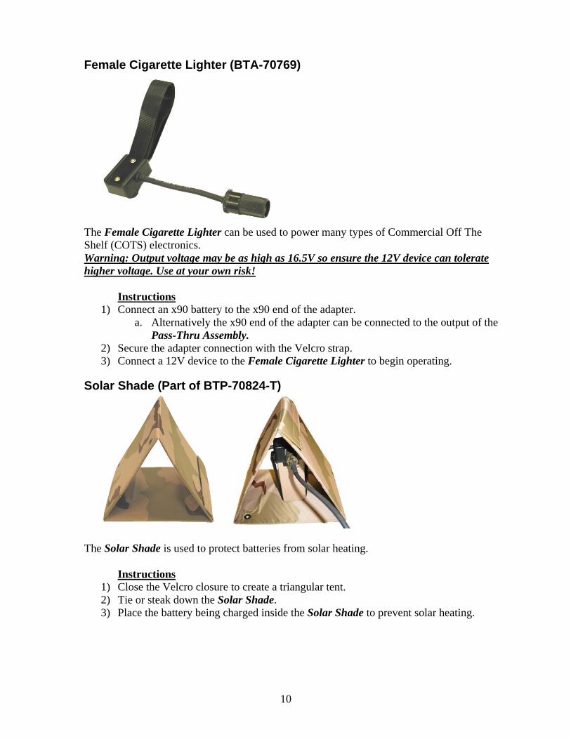
BTA-70781 x90 Output Connecter (Frontal View) and schematic
- (1)
+ (4)
+ (5)
Daisy Chain Connection
- (2)
Charge Adapter Connection
Note: • The Charge Adapter and associated battery are connected to output pins 1(-) & 4(+)
of the x90 Output Connector • If power is connected to the Daisy Chain Input, output pins 2(-) & 5(+) will be
active. o Adding a connection to the Daisy Chain Input allows longer run time or
higher current 12V devices or allows operation of 24V devices. (A device which is designed for an x90 type battery will already be configured properly for this)
Multi Chemistry Charger (BTC-70824-2)
The Multi Chemistry Charger connects directly to a Power Input. It will charge both Li-Ion and NiMH batteries, although charge times will be greater than with the Charge Controller. The Multi Chemistry Charger only charges batteries and does not provide pass-thru power.
Approximate Multi Chemistry Charger charging times: BB-2557/U < 3hrs BB-2590/U 6 – 12 hrs BB-390B/U 6 – 12 hrs

9
Instructions 1) Connect the Multi Chemistry Charger input to the desired power source:
Solar: 55W Solar Panel Connects directly to the Multi Chemistry Charger. AC: 100-230 VAC at 50/60 Hz Use the 591791-1 AC/DC Adapter. DC: 12-16 VDC Use the 591791-1 AC/DC Adapter. 28 VDC Vehicular Power: Use the 393034-1 NATO Slave Plug to connect to
the Multi Chemistry Charger. X90 Primary (BA-5590): Use the BTA-70768 x90 Scavenger to connect to
the Multi Chemistry Charger. See the input options for more detail.
2) Connect a BB-2590/U, BB-2557/U, or BB-390B/U to the Multi-Chemistry Charger
to begin charging. 3) Multi-Chemistry Charger “status” indicator lights during operation are as follows:
• Battery not connected------Slow Blinking Amber Light • Charging---------------------Solid Amber Light • Charge Complete-----------Solid Green Light • Faulty Battery/Charger----Red Light
4) Should there be no indicator lights, disconnect and reconnect the battery and / or check the input power level. If there are still no indicator lights, either the Multi Chemistry Charger or the battery is faulty. Exchange each part one by one with a known good one until correct operation is achieved.
Accessories
8’ Extension (390651)
The 8’ Extension cable allows greater distances between the Power Input and the battery.
Instructions
1) Connect the 8’ Extension cable (if necessary) in between the power source and either the Charge Controller or the Multi Chemistry Charger.
10
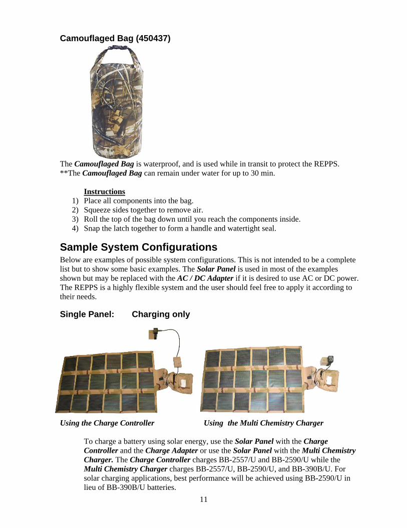
Female Cigarette Lighter (BTA-70769)
The Female Cigarette Lighter can be used to power many types of Commercial Off The Shelf (COTS) electronics. Warning: Output voltage may be as high as 16.5V so ensure the 12V device can tolerate higher voltage. Use at your own risk!
Instructions 1) Connect an x90 battery to the x90 end of the adapter.
a. Alternatively the x90 end of the adapter can be connected to the output of the Pass-Thru Assembly.
2) Secure the adapter connection with the Velcro strap. 3) Connect a 12V device to the Female Cigarette Lighter to begin operating.
Solar Shade (Part of BTP-70824-T)
The Solar Shade is used to protect batteries from solar heating.
Instructions 1) Close the Velcro closure to create a triangular tent. 2) Tie or steak down the Solar Shade. 3) Place the battery being charged inside the Solar Shade to prevent solar heating.
11
Camouflaged Bag (450437)
The Camouflaged Bag is waterproof, and is used while in transit to protect the REPPS. **The Camouflaged Bag can remain under water for up to 30 min.
Instructions
1) Place all components into the bag. 2) Squeeze sides together to remove air. 3) Roll the top of the bag down until you reach the components inside. 4) Snap the latch together to form a handle and watertight seal.
Sample System Configurations Below are examples of possible system configurations. This is not intended to be a complete list but to show some basic examples. The Solar Panel is used in most of the examples shown but may be replaced with the AC / DC Adapter if it is desired to use AC or DC power. The REPPS is a highly flexible system and the user should feel free to apply it according to their needs.
Single Panel: Charging only
Using the Charge Controller Using the Multi Chemistry Charger
To charge a battery using solar energy, use the Solar Panel with the Charge Controller and the Charge Adapter or use the Solar Panel with the Multi Chemistry Charger. The Charge Controller charges BB-2557/U and BB-2590/U while the Multi Chemistry Charger charges BB-2557/U, BB-2590/U, and BB-390B/U. For solar charging applications, best performance will be achieved using BB-2590/U in lieu of BB-390B/U batteries.
12
If using the Charge Controller, 1) Connect the Charge Controller to the Solar Panel. 2) Plug the Charge Controller into the Charge Adapter. 3) Plug the battery into the Charge Adapter and secure it with the Velcro strap. 4) Ensure the proper indicator lights are activated and wait for the charge to complete. If using the Multi Chemistry Charger, 1) Connect the Multi Chemistry Charger to the Solar Panel. 2) Plug the battery into the Multi Chemistry Charger and secure it with the Velcro strap. 3) Ensure the proper indicator light is activated and wait for the charge to complete.
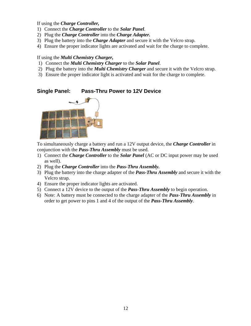
Single Panel: Pass-Thru Power to 12V Device
To simultaneously charge a battery and run a 12V output device, the Charge Controller in conjunction with the Pass-Thru Assembly must be used. 1) Connect the Charge Controller to the Solar Panel (AC or DC input power may be used
as well). 2) Plug the Charge Controller into the Pass-Thru Assembly. 3) Plug the battery into the charge adapter of the Pass-Thru Assembly and secure it with the
Velcro strap. 4) Ensure the proper indicator lights are activated. 5) Connect a 12V device to the output of the Pass-Thru Assembly to begin operation. 6) Note: A battery must be connected to the charge adapter of the Pass-Thru Assembly in
order to get power to pins 1 and 4 of the output of the Pass-Thru Assembly.
13
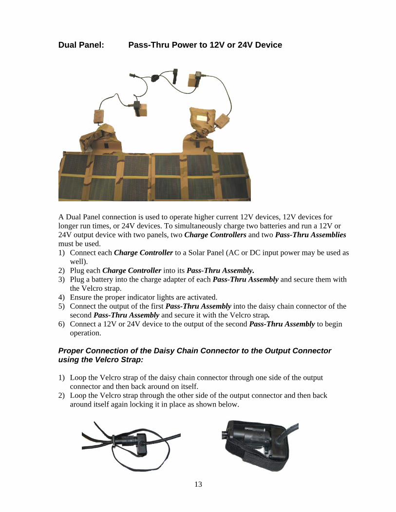
Dual Panel: Pass-Thru Power to 12V or 24V Device
A Dual Panel connection is used to operate higher current 12V devices, 12V devices for longer run times, or 24V devices. To simultaneously charge two batteries and run a 12V or 24V output device with two panels, two Charge Controllers and two Pass-Thru Assemblies must be used. 1) Connect each Charge Controller to a Solar Panel (AC or DC input power may be used as
well). 2) Plug each Charge Controller into its Pass-Thru Assembly. 3) Plug a battery into the charge adapter of each Pass-Thru Assembly and secure them with
the Velcro strap. 4) Ensure the proper indicator lights are activated. 5) Connect the output of the first Pass-Thru Assembly into the daisy chain connector of the
second Pass-Thru Assembly and secure it with the Velcro strap. 6) Connect a 12V or 24V device to the output of the second Pass-Thru Assembly to begin
operation. Proper Connection of the Daisy Chain Connector to the Output Connector using the Velcro Strap: 1) Loop the Velcro strap of the daisy chain connector through one side of the output
connector and then back around on itself. 2) Loop the Velcro strap through the other side of the output connector and then back
around itself again locking it in place as shown below.

14
Single Panel with Additional Battery: 12V or 24V Device
A single panel with an additional battery connection is used to operate higher current 12V devices, 12V devices for longer run times, or 24V devices. To simultaneously charge a battery and run a 12V or 24V output device with an additional battery, the Charge Controller in conjunction with the Pass-Thru Assembly must be used. 1) Connect the Charge Controller to the Solar Panel (AC or DC input power may be used
as well). 2) Plug the Charge Controller into the Pass-Thru Assembly. 3) Plug a battery into the charge adapter of the Pass-Thru Assembly and secure it with the
Velcro strap. 4) Ensure the proper indicator lights are activated. 5) Plug the additional battery into the daisy chain connector of the Pass-Thru Assembly. 6) Connect a 12V or 24V device to the output of the Pass-Thru Assembly to begin
operation. 7) Notes:
• A battery must be connected to the charge adapter of the Pass-Thru Assembly in order to get power to pins 1 and 4 of the output of the Pass-Thru Assembly.
• The daisy chain connector is input only and does not charge the additional battery therefore the additional battery has a finite run-time.
AC Power: Charging Only
Using the Charge Controller Using the Multi Chemistry Charger
To charge a battery using AC power, use the AC / DC Adapter with the Charge Controller and the Charge Adapter or use the AC / DC Adapter with the Multi Chemistry Charger. The Charge Controller charges BB-2557/U and BB-2590/Us while the Multi Chemistry Charger charges BB-2557/U, BB-2590/U, and BB-390B/U. If using the Charge Controller, 1) Connect the AC / DC Adapter to the AC power source. The blue indicator LED should
light if proper power is applied.
15
2) Connect the Charge Controller to the AC / DC Adapter. 3) Plug the Charge Controller into the Charge Adapter. 4) Plug the battery into the Charge Adapter and secure it with the Velcro strap. 5) Ensure the proper indicator lights are activated and wait for the charge to complete. If using the Multi Chemistry Charger, 1) Connect the AC / DC Adapter to the AC power source. The blue indicator LED should
light if proper power is applied. 2) Connect the Multi Chemistry Charger to the AC / DC Adapter. 3) Plug the battery into the Multi Chemistry Charger and secure it with the Velcro strap. 4) Ensure the proper indicator light is activated and wait for the charge to complete.
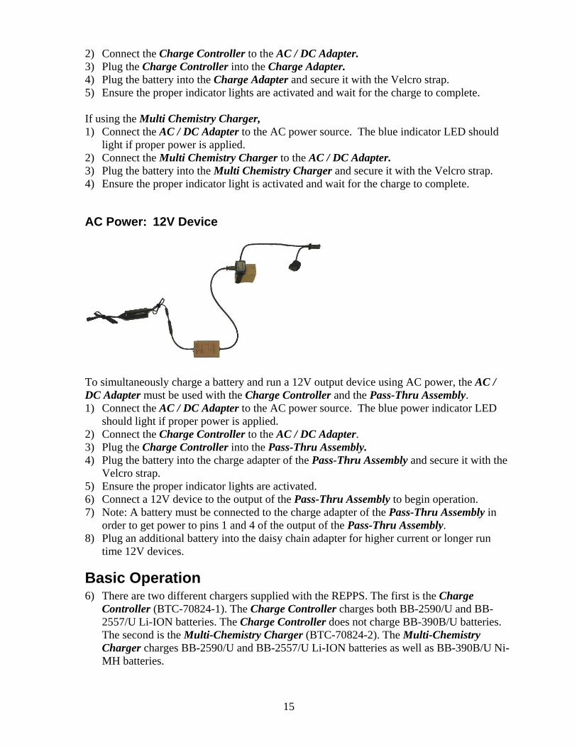
AC Power: 12V Device
To simultaneously charge a battery and run a 12V output device using AC power, the AC / DC Adapter must be used with the Charge Controller and the Pass-Thru Assembly. 1) Connect the AC / DC Adapter to the AC power source. The blue power indicator LED
should light if proper power is applied. 2) Connect the Charge Controller to the AC / DC Adapter. 3) Plug the Charge Controller into the Pass-Thru Assembly. 4) Plug the battery into the charge adapter of the Pass-Thru Assembly and secure it with the
Velcro strap. 5) Ensure the proper indicator lights are activated. 6) Connect a 12V device to the output of the Pass-Thru Assembly to begin operation. 7) Note: A battery must be connected to the charge adapter of the Pass-Thru Assembly in
order to get power to pins 1 and 4 of the output of the Pass-Thru Assembly. 8) Plug an additional battery into the daisy chain adapter for higher current or longer run
time 12V devices.
Basic Operation 6) There are two different chargers supplied with the REPPS. The first is the Charge
Controller (BTC-70824-1). The Charge Controller charges both BB-2590/U and BB-2557/U Li-ION batteries. The Charge Controller does not charge BB-390B/U batteries. The second is the Multi-Chemistry Charger (BTC-70824-2). The Multi-Chemistry Charger charges BB-2590/U and BB-2557/U Li-ION batteries as well as BB-390B/U Ni-MH batteries.
16
When using the BTC-70824-1 Charge Controller, the battery is connected to the charge controller via the BTA-70781 or BTA-70782 charge adapters. Each charge adapter charges one battery at a time. The charge adapters serve as the electrical interface between the batteries being charged and the charge controller. When using the BTC-70824-2 Multi-Chemistry Charger, the battery is connected directly to the charger as no adapter is required. Both chargers constantly monitor the voltage, current, and charging time during the charge cycle to ensure the battery is properly being charged. The charger operation during a typical charge sequence is automatic and the battery charge status is displayed to the user by the LED indicators as follows:
a. Charging – A timed fast charge cycle brings the battery to approximately 90% of full charge capacity. The CHARGE STATUS LED is lit steady amber during this process. The LED indicators for both the “A” side and the “B” side should show an indication for the BTC-70824-1 Charge Controller.
b. Ready – The fast charge cycle is complete. The Battery may be removed and used at this time. The CHARGE STATUS LED is lit steady green at this time. The LED indicators for both the “A” side and the “B” side should indicate green for the battery to be fully charged for the BTC-70824-1 Charge Controller.
c. Fault – The battery did not charge properly and should not be used. Check the battery and the charging system for problems. The CHARGE STATUS LED is lit steady red at this time. If the LED indicator for either the “A” side or the “B” side is red for the BTC-70824-1 Charge Controller, then the battery did not charge properly and should not be used.
The Battery may be removed and used at anytime during the charge cycle without damage to the charger or battery. The battery’s state-of-charge (SOC) indicator will display the battery condition.
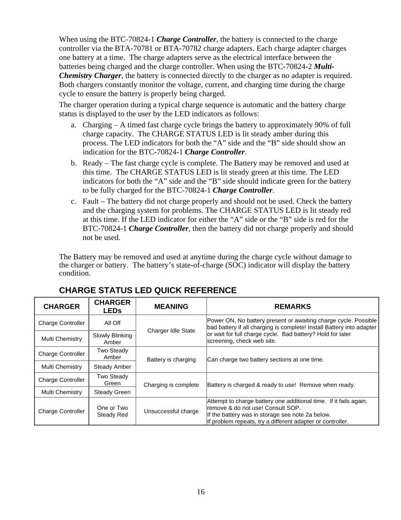
CHARGE STATUS LED QUICK REFERENCE
CHARGER CHARGER LEDs MEANING REMARKS
Charge Controller All Off
Multi Chemistry Slowly Blinking Amber
Charger Idle State
Power ON, No battery present or awaiting charge cycle. Possible bad battery if all charging is complete! Install Battery into adapter or wait for full charge cycle. Bad battery? Hold for later screening, check web site.
Charge Controller Two Steady Amber
Multi Chemistry Steady Amber Battery is charging Can charge two battery sections at one time.
Charge Controller Two Steady Green
Multi Chemistry Steady Green Charging is complete Battery is charged & ready to use! Remove when ready.
Charge Controller One or Two Steady Red Unsuccessful charge
Attempt to charge battery one additional time. If it fails again, remove & do not use! Consult SOP. If the battery was in storage see note 2a below. If problem repeats, try a different adapter or controller.
17
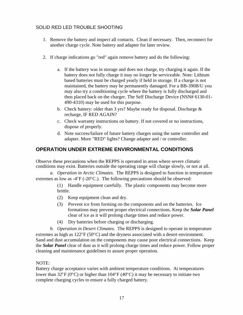
SOLID RED LED TROUBLE SHOOTING
1. Remove the battery and inspect all contacts. Clean if necessary. Then, reconnect for another charge cycle. Note battery and adapter for later review.
2. If charge indications go "red" again remove battery and do the following:
a. If the battery was in storage and does not charge, try charging it again. If the battery does not fully charge it may no longer be serviceable. Note: Lithium based batteries must be charged yearly if held in storage. If a charge is not maintained, the battery may be permanently damaged. For a BB-390B/U you may also try a conditioning cycle where the battery is fully discharged and then placed back on the charger. The Self Discharge Device (NSN# 6130-01-490-4310) may be used for this purpose.
b. Check battery: older than 3 yrs? Maybe ready for disposal. Discharge & recharge, IF RED AGAIN?
c. Check warranty instructions on battery. If not covered or no instructions, dispose of properly.
d. Note success/failure of future battery charges using the same controller and adapter. More "RED" lights? Change adapter and / or controller.
OPERATION UNDER EXTREME ENVIRONMENTAL CONDITIONS Observe these precautions when the REPPS is operated in areas where severe climatic conditions may exist. Batteries outside the operating range will charge slowly, or not at all.
a. Operation in Arctic Climates. The REPPS is designed to function in temperature extremes as low as -4°F (-20°C.). The following precautions should be observed:
(1) Handle equipment carefully. The plastic components may become more brittle. (2) Keep equipment clean and dry. (3) Prevent ice from forming on the components and on the batteries. Ice
formations may prevent proper electrical connections. Keep the Solar Panel clear of ice as it will prolong charge times and reduce power.
(4) Dry batteries before charging or discharging. b. Operation in Desert Climates. The REPPS is designed to operate in temperature
extremes as high as 122°F (50°C) and the dryness associated with a desert environment. Sand and dust accumulation on the components may cause poor electrical connections. Keep the Solar Panel clear of dust as it will prolong charge times and reduce power. Follow proper cleaning and maintenance guidelines to assure proper operation. NOTE: Battery charge acceptance varies with ambient temperature conditions. At temperatures lower than 32°F (0°C) or higher than 104°F (40°C) it may be necessary to initiate two complete charging cycles to ensure a fully charged battery.

18
Maintenance Periodic maintenance, inspection and cleaning will help insure the REPPS is kept at full readiness.
Cleaning 1. Brush loose dirt and dust from all components of the system. Low-pressure air may
be used to remove heavy dust from the inside of connectors. 2. External surfaces maybe wiped with a wet rag. Non-solvent cleaners may be used
(Windex™, Fantastik™, Formula 409™ or equivalent). 3. The connections on the Adapters may be cleaned with electronic grade spray cleaner
or isopropyl alcohol. Ensure the Adapters are dry before using them.
Inspection 1. Inspect cases for cracks and other damage. 2. Inspect connectors for damage including bent or corroded pins. 3. Inspect adapters for excessive wear and damage. 4. Inspect cables for damage.
19
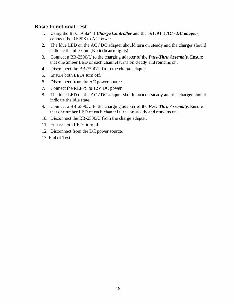
Basic Functional Test 1. Using the BTC-70824-1 Charge Controller and the 591791-1 AC / DC adapter,
connect the REPPS to AC power. 2. The blue LED on the AC / DC adapter should turn on steady and the charger should
indicate the idle state (No indicator lights). 3. Connect a BB-2590/U to the charging adapter of the Pass-Thru Assembly. Ensure
that one amber LED of each channel turns on steady and remains on. 4. Disconnect the BB-2590/U from the charge adapter. 5. Ensure both LEDs turn off. 6. Disconnect from the AC power source. 7. Connect the REPPS to 12V DC power. 8. The blue LED on the AC / DC adapter should turn on steady and the charger should
indicate the idle state. 9. Connect a BB-2590/U to the charging adapter of the Pass-Thru Assembly. Ensure
that one amber LED of each channel turns on steady and remains on. 10. Disconnect the BB-2590/U from the charge adapter. 11. Ensure both LEDs turn off. 12. Disconnect from the DC power source. 13. End of Test.

20
Simplified Operator Troubleshooting Procedures
Item MALFUNCTION POSSIBLE CORRECTIVE ACTION
1 Blue POWER ON LED is not lit during AC operation.
1) Check for proper source voltage. 2) Inspect Power Cord for proper connection. 3) Inspect Power Cord for damage.
2 Blue POWER ON LED is not lit during DC operation.
1) Check for proper source voltage. 2) Inspect Power Cord for proper connection. 3) Inspect Power Cord for damage.
3 Red FAULT LED is lit.
1) Check battery: older than 3 yrs? Maybe ready for disposal. Discharge & Recharge, IF RED AGAIN?
2) Check warranty instructions on battery. If not covered or no instructions, dispose of properly.
3) Note success/failure of future battery charges using this controller. More "RED" lights? Change adapter.
4 Charging does not start.
1) Possible poor connection. Inspect and clean battery and Adapter contact.
2) Defective Adapter. Use a different adapter. 3) Defective Charge Controller. Try a different
Charge Controller. 4) Defective Battery, replace.
5 LED goes to Amber (CHARGE), but never turns Red (FAULT) or Green (READY), instead it turns off.
1) Poor Connection, inspect and clean battery and adapter contact.
2) Defective Adapter. Use a different adapter. 3) Defective Charge Controller. Try a different
Charge Controller. 4) Defective Battery, replace.
Warranty / Repair Information If any portion of the REPPS system fails to function it must be returned to Bren-Tronics for repair. There are no user repairable parts in the REPPS. Contact Bren-Tronics for an RMA Number for proper return authorization. Have a description of the reason the component requires repair. Parts that have been damaged by abuse or that are no longer under warranty may be returned for a repair quote. Opening any components of the REPPS voids the warranty. For return authorization call (631) 499-5155 or email [email protected]

