r&s®cldg docsis cable load generator - rohde & · pdf filerohde & schwarz...
TRANSCRIPT
Broa
dcas
t & M
edia
Test
& M
easu
rem
ent
Prod
uct B
roch
ure
| 02.
00
R&S®CLGDDOCSIS Cable Load GeneratorMultichannel signal generator for DOCSIS 3.1 downstream and upstream
CLGD_bro_en_3607-0123-12_v0200.indd 1 24.07.2015 08:03:30

2
or internally generated by the R&S®CLGD. The upstream frequency range is 5 MHz to 204 MHz. Within this range, DOCSIS 3.1 orthogonal frequency division multiple access (OFDMA) signals can be freely combined with DOCSIS 3.0 TDMA or CDMA signals.
The flexible multichannel signal generation capabilities of the R&S®CLGD enable it to simulate network loading in a reproducible manner, making it ideal for testing tuners, cable modems and upstream CMTS receivers. The influ-ence of QAM and TDMA/CDMA signals in adjacent chan-nels on DOCSIS 3.1 signal reception is a research topic of great interest. The R&S®CLGD makes such simulations realistic by adding different types of interference, such as noise, reflections and narrowband interference.
The generator is accommodated in a 19" housing that takes up a mere two height units. The complex signal gen-eration process can be conveniently controlled from a PC or via a web interface. Remote control through SCPI com-mands enables the generator to be used in automatic test systems. The R&S®CLGD can be adapted to various appli-cation requirements thanks to its software option concept.
Key facts ❙ Frequency range in downstream: 47 MHz to 1218 MHz, extendable to 1794 MHz
❙ Frequency range in upstream: 5 MHz to 204 MHz ❙ DOCSIS 3.1, DOCSIS 3.0, J.83/A/B/C and analog TV ❙ Up to eight times 192 MHz signal bandwidth for DOCSIS 3.1
❙ ARB generator bandwidth up to 200 MHz
R&S®CLGD DOCSIS Cable Load GeneratorAt a glance
The R&S®CLGD is the first generator that simultaneously produces signals for DOCSIS 3.1, DOCSIS 3.0, digital cable TV in line with J.83/A/B/C and analog cable TV. Its downstream frequency range is 108 MHz to 1794 MHz for DOCSIS 3.1 and 47 MHz to 1218 MHz for TV. Within this range, the R&S®CLGD generates multiple DOCSIS 3.1 channels with up to 192 MHz bandwidth each. The level, frequency, forward error correction (FEC) and constellation of these channels can be set independently. At the same time, the R&S®CLGD produces a large number of digital and analog TV signals that can be placed anywhere be-low or between the DOCSIS 3.1 signals. The DOCSIS 3.1 channels and digital TV channels are implemented in realtime. The data to be transmitted can be fed in via IP
The R&S®CLGD is a multichannel signal generator for simulating a cable TV network with full channel loading. It generates broadband data signals for DOCSIS 3.1 as well as digital and analog TV channels. In the downstream or upstream, signals can be freely combined, allowing users to simulate any conceivable channel loading scenario in the lab.
CLGD_bro_en_3607-0123-12_v0200.indd 2 24.07.2015 08:03:32
Rohde & Schwarz R&S®CLGD DOCSIS Cable Load Generator 3
R&S®CLGD DOCSIS Cable Load GeneratorBenefits and key features
Signal generation for channel loading scenarios in the downstream ❙ Realtime modulation of DOCSIS 3.1 and J.83/A/B/C ❙ Combined load simulation of DOCSIS 3.1, digital and analog TV ▷ page 4
Cable modem data traffic simulation in the upstream ❙ Any combination of OFDMA, TDMA and CDMA signals ❙ Trigger function for burst timing control ▷ page 5
Signal interference and distortion simulation ❙ Noise, impulsive noise and phase noise ❙ Microreflections ❙ AC hum ❙ Uptilt and downtilt ❙ Ingress simulation with superimposed interference signals ▷ page 6
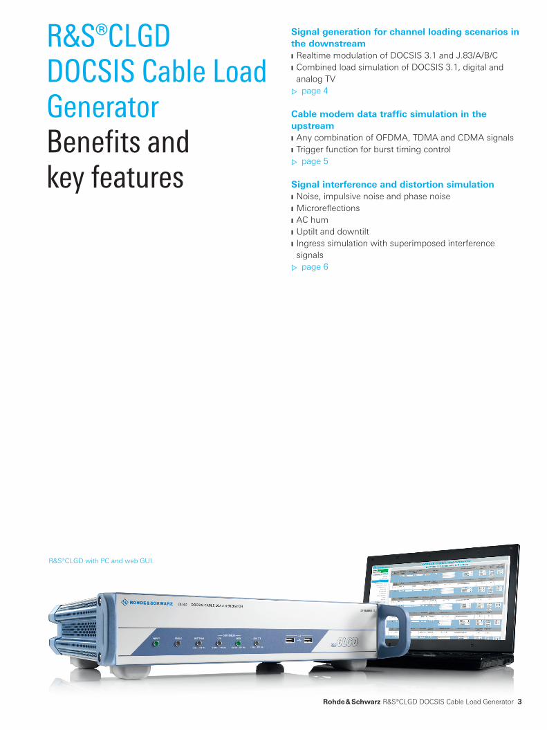
R&S®CLGD with PC and web GUI.
CLGD_bro_en_3607-0123-12_v0200.indd 3 24.07.2015 08:03:34
1794 MHz1002 MHz204 MHz 258 MHz5 MHz
••• •••
1218 MHz1002 MHz5 MHz
••••••••••••••••••••••••••••••
47 MHz
1002 MHz5 MHz
••••••
47 MHz
•••
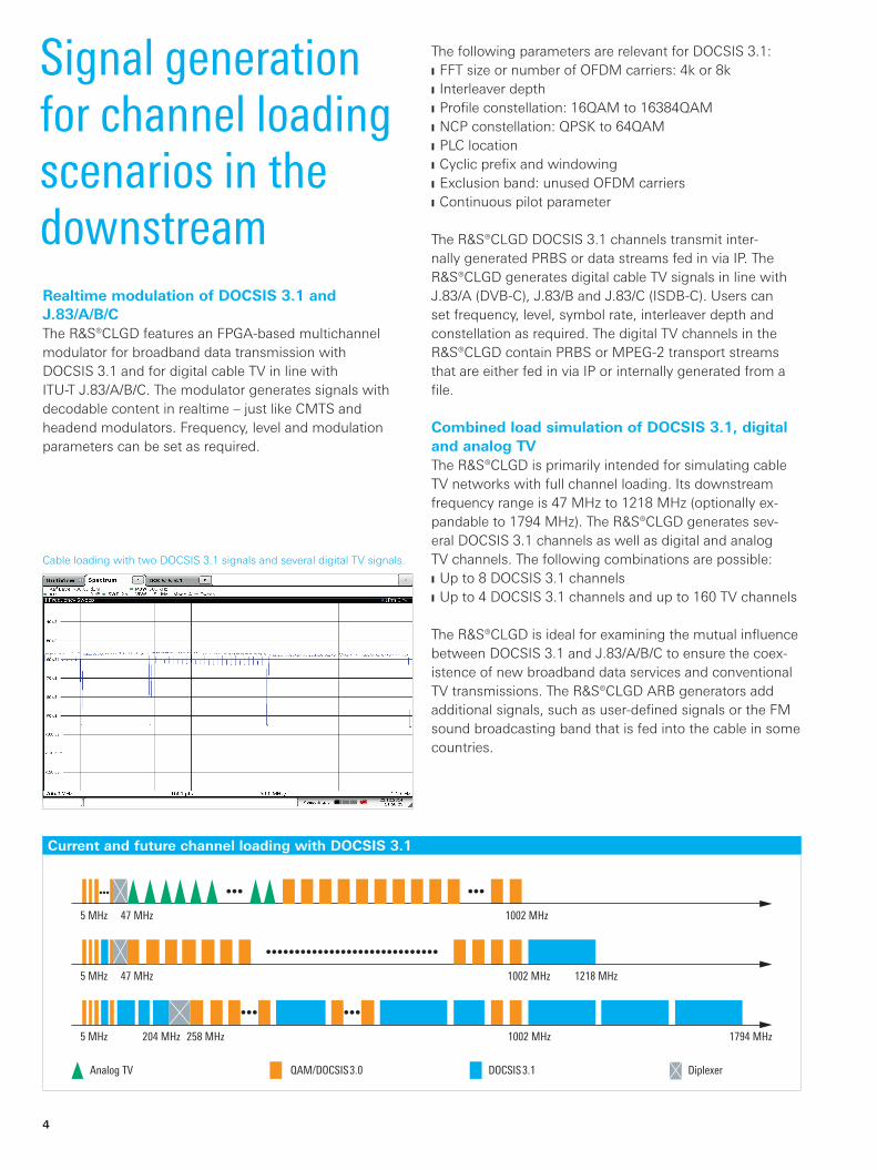
Analog TV QAM/DOCSIS3.0 DOCSIS3.1 Diplexer
4
Signal generation for channel loading scenarios in the downstream
Current and future channel loading with DOCSIS 3.1
Realtime modulation of DOCSIS 3.1 and J.83/A/B/CThe R&S®CLGD features an FPGA-based multichannel modulator for broadband data transmission with DOCSIS 3.1 and for digital cable TV in line with ITU-T J.83/A/B/C. The modulator generates signals with decodable content in realtime – just like CMTS and headend modulators. Frequency, level and modulation parameters can be set as required.
Cable loading with two DOCSIS 3.1 signals and several digital TV signals.
The following parameters are relevant for DOCSIS 3.1: ❙ FFT size or number of OFDM carriers: 4k or 8k ❙ Interleaver depth ❙ Profile constellation: 16QAM to 16384QAM ❙ NCP constellation: QPSK to 64QAM ❙ PLC location ❙ Cyclic prefix and windowing ❙ Exclusion band: unused OFDM carriers ❙ Continuous pilot parameter
The R&S®CLGD DOCSIS 3.1 channels transmit inter-nally generated PRBS or data streams fed in via IP. The R&S®CLGD generates digital cable TV signals in line with J.83/A (DVB-C), J.83/B and J.83/C (ISDB-C). Users can set frequency, level, symbol rate, interleaver depth and constellation as required. The digital TV channels in the R&S®CLGD contain PRBS or MPEG-2 transport streams that are either fed in via IP or internally generated from a file.
Combined load simulation of DOCSIS 3.1, digital and analog TVThe R&S®CLGD is primarily intended for simulating cable TV networks with full channel loading. Its downstream frequency range is 47 MHz to 1218 MHz (optionally ex-pandable to 1794 MHz). The R&S®CLGD generates sev-eral DOCSIS 3.1 channels as well as digital and analog TV channels. The following combinations are possible: ❙ Up to 8 DOCSIS 3.1 channels ❙ Up to 4 DOCSIS 3.1 channels and up to 160 TV channels
The R&S®CLGD is ideal for examining the mutual influence between DOCSIS 3.1 and J.83/A/B/C to ensure the coex-istence of new broadband data services and conventional TV transmissions. The R&S®CLGD ARB generators add additional signals, such as user-defined signals or the FM sound broadcasting band that is fed into the cable in some countries.
CLGD_bro_en_3607-0123-12_v0200.indd 4 24.07.2015 08:03:34

Control interface
5 MHz to
204 MHz
LAN
2 × SFP+
Trigger
Digital upconversion
47 MHz to
1218 MHz
252 MHz to
1794 MHz
Input data interface
DownstreamDOCSIS 3.1/DOCSIS 3.0J.83/A/B/C
ARB generator
ARB generator
UpstreamDOCSIS 3.1/DOCSIS 3.0
Burst noise
Microreflections
UpstreamDAC
AWGN
Downstreamlow band DAC
Downstreamhigh bandDAC
MPEG file playout
Narrowbandinterferer
AC hum
Phase noise
Rohde & Schwarz R&S®CLGD DOCSIS Cable Load Generator 5
Cable modem data traffic simulation in the upstream
Any combination of OFDMA, TDMA and CDMA signalsThe upstream spectrum that arrives at the CMTS receiver consists of transmissions from many individual cable modems. The R&S®CLGD generates this spectrum in the frequency range from 5 MHz to 204 MHz with a maxi-mum of two DOCSIS 3.1 OFDMA channels and up to 32 DOCSIS 3.0 channels with TDMA or CDMA, effectively simulating the data traffic from a large number of cable modems. TDMA and CDMA signals always contain data packets. DOCSIS 3.1 signals contain different message types (see table). The R&S®CLGD ARB generators can also add user-defined signals in the upstream.
Trigger function for burst timing controlCable modems transmit short, time-limited data packets (bursts). If there is a sufficiently high number of modems in the network, the individual bursts are superimposed to generate an almost continuous signal. For DOCSIS 3.1, the result is an OFDM signal in which different modems occupy different parts of the subcarrier. For DOCSIS 3.0 TDMA, the result is a pulsed signal with individual bursts from different modems. For use as a load generator, the R&S®CLGD generates exactly the type of signals needed to simulate the data traffic sum of multiple modems. The R&S®CLGD can also generate individual bursts in a single channel. The burst timing is controlled by the trigger func-tion, making it possible to simulate modem ranging when registering with a CMTS.
Overview of the R&S®CLGD interfaces and function blocks
Signal types in the upstreamStandard Modulation Message type
DOCSIS 3.1 OFDMA data packet,bandwidth request,initial ranging,fine ranging,wideband probe
DOCSIS 3.0 A-TDMA data packet
S-CDMA data packet
CLGD_bro_en_3607-0123-12_v0200.indd 5 24.07.2015 08:03:35
6
Signal interference and distortion simulationThe R&S®CLGD can add interference to the output signal to simulate realistic receive conditions, making it ideal for testing cable modems, amplifiers and upstream CMTS receivers.
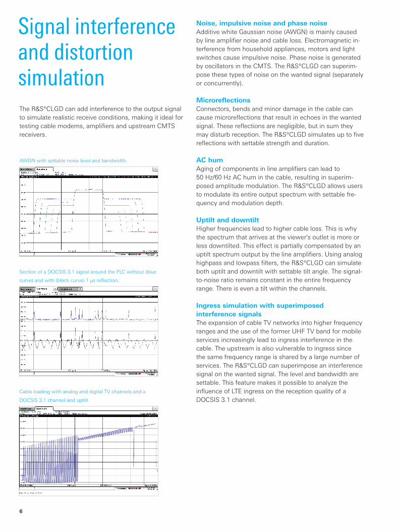
Noise, impulsive noise and phase noiseAdditive white Gaussian noise (AWGN) is mainly caused by line amplifier noise and cable loss. Electromagnetic in-terference from household appliances, motors and light switches cause impulsive noise. Phase noise is generated by oscillators in the CMTS. The R&S®CLGD can superim-pose these types of noise on the wanted signal (separately or concurrently).
MicroreflectionsConnectors, bends and minor damage in the cable can cause microreflections that result in echoes in the wanted signal. These reflections are negligible, but in sum they may disturb reception. The R&S®CLGD simulates up to five reflections with settable strength and duration.
AC humAging of components in line amplifiers can lead to 50 Hz/60 Hz AC hum in the cable, resulting in superim-posed amplitude modulation. The R&S®CLGD allows users to modulate its entire output spectrum with settable fre-quency and modulation depth.
Uptilt and downtiltHigher frequencies lead to higher cable loss. This is why the spectrum that arrives at the viewer's outlet is more or less downtilted. This effect is partially compensated by an uptilt spectrum output by the line amplifiers. Using analog highpass and lowpass filters, the R&S®CLGD can simulate both uptilt and downtilt with settable tilt angle. The signal-to-noise ratio remains constant in the entire frequency range. There is even a tilt within the channels.
Ingress simulation with superimposed interference signalsThe expansion of cable TV networks into higher frequency ranges and the use of the former UHF TV band for mobile services increasingly lead to ingress interference in the cable. The upstream is also vulnerable to ingress since the same frequency range is shared by a large number of services. The R&S®CLGD can superimpose an interference signal on the wanted signal. The level and bandwidth are settable. This feature makes it possible to analyze the influence of LTE ingress on the reception quality of a DOCSIS 3.1 channel.
Cable loading with analog and digital TV channels and a
DOCSIS 3.1 channel and uptilt.
Section of a DOCSIS 3.1 signal around the PLC without (blue
curve) and with (black curve) 1 μs reflection.
AWGN with settable noise level and bandwidth.
CLGD_bro_en_3607-0123-12_v0200.indd 6 24.07.2015 08:03:35

Rohde & Schwarz R&S®CLGD DOCSIS Cable Load Generator 7
Specifications in briefSpecifications in brief RF parameters
Frequency range downstream 47 MHz to 1218 MHz
with R&S®CLGD-K3018 option 47 MHz to 1794 MHz
upstream 5 MHz to 204 MHz
Level adjustable up to max. 62 dBmV
Tilt adjustable up to ±15 dB (1 GHz)
MER DOCSIS 3.1, f = 500 MHz, B = 192 MHz typ. > 53 dB
2 × 192 MHz DOCSIS 3.1 and 24 × J.83/A/B/C and f < 600 MHz
≥ 50 dB
1 × J.83/A/B/C typ. > 45 dB
Multichannel signal generation downstream up to 5 × DOCSIS 3.1 or up to 2 × DOCSIS 3.1 and 158 × QAM
with R&S®CLGD-K3018 option up to 8 × DOCSIS 3.1 or up to 4 × DOCSIS 3.1 and 158 × QAM
upstream up to 2 × DOCSIS 3.1 and 32 × DOCSIS 3.0
Downstream modulation (R&S®CLGD-K200 option)
DOCSIS 3.1 bandwidth up to 192 MHz
constellation 16QAM to 4096QAM, overrange 8kQAM, 16kQAM
FFT mode 4k, 8k
J.83/A/B/C bandwidth 6 MHz, 7 MHz, 8 MHz
constellation 64QAM, 256QAM
Analog TV PAL, NTSC
Upstream modulation (R&S®CLGD-K300 option)
DOCSIS 3.1 modulation mode OFDMA
bandwidth 6.4 MHz to 96 MHz
DOCSIS 3.0 modulation mode A-TDMA, S-CDMA
bandwidth 800 kHz, 1.6 MHz, 3.2 MHz, 6.4 MHz
ARB waveform generator
Bandwidth 200 MHz
Number of files played simultaneously up to 10 MHz bandwidth 4
10 MHz to 100 MHz bandwidth 2
100 MHz to 200 MHz bandwidth 1
Interference simulation (R&S®CLGD-K1050 option)
Noise AWGN, impulsive noise, phase noise
Microreflections up to 5 reflections
AC hum amplitude modulation 47 Hz to 200 Hz, 0 % to 6 %
Narrowband interference AWGN up to 20 MHz bandwidth
Designation Type Order No.DOCSIS Cable Load Generator, for TV and DOCSIS (base unit incl. power cable, quick start guide and CD-ROM with user manual)
R&S®CLGD 2118.6956.02
Options
Downstream Full Channel Load Generator R&S®CLGD-K200 2118.6962.02
Upstream Cable Modem Emulator R&S®CLGD-K300 2118.6979.02
Downstream Frequency Range Extension to 1794 MHz R&S®CLGD-K3018 2118.6985.02
Signal Interference Simulation R&S®CLGD-K1050 2118.6991.02
External accessories
Multi-TS Streaming Software R&S®TSStream 2116.8945.02
Ordering information
CLGD_bro_en_3607-0123-12_v0200.indd 7 24.07.2015 08:03:36
R&S® is a registered trademark of Rohde & Schwarz GmbH & Co. KG
Trade names are trademarks of the owners
PD 3607.0123.12 | Version 02.00 | July 2015 (ch)
R&S®CLGD DOCSIS Cable Load Generator
Data without tolerance limits is not binding | Subject to change
© 2015 Rohde & Schwarz GmbH & Co. KG | 81671 Munich, Germany
Service that adds value❙ Worldwide ❙ Local and personalized❙ Customized and flexible❙ Uncompromising quality ❙ Long-term dependability
3607
.012
3.12
02.
00 P
DP
1 e
n
About Rohde & SchwarzThe Rohde & Schwarz electronics group offers innovative solutions in the following business fields: test and mea-surement, broadcast and media, secure communications, cybersecurity, radiomonitoring and radiolocation. Founded more than 80 years ago, this independent company has an extensive sales and service network and is present in more than 70 countries. The electronics group is among the world market leaders in its established business fields. The company is headquartered in Munich, Germany. It also has regional headquarters in Singapore and Columbia, Maryland, USA, to manage its operations in these regions.
Sustainable product design ❙ Environmental compatibility and eco-footprint ❙ Energy efficiency and low emissions ❙ Longevity and optimized total cost of ownership
Certified Environmental Management
ISO 14001Certified Quality Management
ISO 9001
Regional contact ❙ Europe, Africa, Middle East | +49 89 4129 12345 [email protected]
❙ North America | 1 888 TEST RSA (1 888 837 87 72) [email protected]
❙ Latin America | +1 410 910 79 88 [email protected]
❙ Asia Pacific | +65 65 13 04 88 [email protected]
❙ China | +86 800 810 82 28 | +86 400 650 58 96 [email protected]
Rohde & Schwarz GmbH & Co. KGwww.rohde-schwarz.com
3607012312
CLGD_bro_en_3607-0123-12_v0200.indd 8 24.07.2015 08:03:36