royal vendors, inc. giii plus · royal vendors, inc. operation and service manual giii plus royal...
TRANSCRIPT
Royal Vendors, Inc.
Operation and Service Manual
GIII Plus
Royal Vendors, Inc. • 426 Industrial Boulevard • Kearneysville WV 25430-2776 • USATelephone +1 304 728 7056 • Fax +1 304 725 4016 • [email protected] • [email protected] • www.royalvendors.com
Manufactured by
R

Royal Vendors, Inc. • 426 Industrial Boulevard • Kearneysville WV 25430-2776 • USACustomer Service: +1 304 728 7056 • Fax +1 304 725 4016
E-mail: [email protected]@royalvendors.com
Website: www.royalvendors.com
Table of Contents
Safety Information .................................................................................................................... 5
SECTION 1. General Information and Setup ......................................................................... 7 Introduction .............................................................................................................................. 7 Unpacking the Vender and Installing It On Location ................................................................ 7 Voltage Requirements and Vender’s Power Cord ................................................................... 7 Vender Identification ................................................................................................................ 8 Specifications ........................................................................................................................... 8
SECTION 2. Vender Component Explanation ....................................................................... 9 Vender Control Board (including pinouts) ................................................................................ 9 Low Voltage Transformer ....................................................................................................... 12 Delivery Chute Sensor ........................................................................................................... 13 Vend Mechanism Assembly ................................................................................................... 13 Vend Mechanism Components .............................................................................................. 13 Refrigeration System ............................................................................................................. 15 Ballast .................................................................................................................................... 16
SECTION 3. Vender Programming ....................................................................................... 17 Introduction to Four-button Programming .............................................................................. 17 EMS Software ........................................................................................................................ 17 Menu System ......................................................................................................................... 17 Internal (Service) Menu ......................................................................................................... 18 Error Code Display Mode (Eror) ......................................................................................... 18 Coin Pay Out Mode (CPO) .................................................................................................... 20 Tube Fill Mode (tUFL) .......................................................................................................... 20 Recycler Pay Out Mode (rPO) ............................................................................................. 20 Test Modes (tESt) ................................................................................................................ 20 Password Protection (PASS) ................................................................................................. 21 Cash Counter Display Mode (CASH) ..................................................................................... 21 Sale Counter Display Mode (SALE) ...................................................................................... 21 Card Counter Display Mode (CArd) ..................................................................................... 22 Token Counter Display Mode (toKn) .................................................................................... 22 Free Vend Accounting Mode (FrEE) ..................................................................................... 23 Price Setting Mode (PriC) ................................................................................................... 23 Space-to-Sales Programming Mode (StS) .......................................................................... 24 Configurations Mode (Con) .................................................................................................. 25 Correct Change Only Control Mode (CCOC) .......................................................................... 27 Password Preview Mode (PrEU) .......................................................................................... 27 Language Selection Mode (LAnG) ........................................................................................ 28 Time Programming Mode (tinE) ......................................................................................... 28 Lighting Control Mode (Lit) ................................................................................................ 30 Refrigeration Control Mode (rFrG) ....................................................................................... 32 Block Selection 1 (bLC1) / Block Selection 2 (bLC2) ............................................................. 34 Selection Discounting Mode (dISC) ...................................................................................... 36
Table of Contents (continued)
Manual Switch Override (OUEr) ............................................................................................ 37 Selection Depth Setting Mode (SdEP) .................................................................................. 39 Remote Vend Mechanism Routine (rUnd) ........................................................................... 39 Return to Sales (rtn) ........................................................................................................... 40 External Menu ........................................................................................................................ 41 Sales Counters (SALE) ......................................................................................................... 41 Cash Counters (CASH) .......................................................................................................... 41 Error Codes (Eror) .............................................................................................................. 41 Return to Sales (rtn) ........................................................................................................... 41
SECTION 4. Vend Cycle ........................................................................................................ 42
SECTION 5. Vender Maintenance ......................................................................................... 43
SECTION 6. Vender Troubleshooting .................................................................................. 44 Using the Vender’s Error Code System ................................................................................. 44 Troubleshooting ..................................................................................................................... 48 Electronic Refrigeration Troubleshooting Flow Chart ............................................................ 53
SECTION 7. Training Guide .................................................................................................. 54
SECTION 8. Parts Catalogue ................................................................................................ 58
SECTION 9. Wiring Diagram ................................................................................................. 76
SECTION 10. Programming Flowchart ................................................................................ 78
CREDIT AND REPLACEMENT POLICY ..................................................................Back Cover
GIII Plus Operation and Service Manual 5
Safety Information
Safety InformationRoyal Vendors’ Commitment to SafetyRoyal Vendors is committed to safety with all of our product designs. We are committed to notifying the user of a possible danger involving the improper handling or maintenance of our venders. The servicing of any electrical or mechanical device involves potential dangers, both to those servicing the equipment and to users of the equipment. These dangers can occur because of improper maintenance or usage. The purpose of this safety segment is to alert everyone servicing Royal equipment of potentially dangerous areas, and to provide basic safety guidelines for proper upkeep.
The service manual contains various warnings that should be carefully read to minimize the risk of personal injury. This manual also contains service information to insure that proper methods are followed to avoid damaging the vender or making it unsafe. It is also important to understand these warnings provide general guidance only. Royal could not possibly know, evaluate, or advise of all of the conceivable ways in which service might be done. Consequently, Royal cannot predict all of the possible dangerous results. These outlined safety precautions are the basis for an effective safety program. Use these safety measures, along with the service bulletins, helpful hints and product specification sheets, when installing or servicing Royal equipment.
We recommend that persons servicing our equipment maintain a similar commitment to safety. Only personnel properly trained should have access to the interior of the vender. This will minimize the potential dangers that are inherent in electrical and mechanical devices. Royal has no control over the vender once it leaves the premises. It is the owner or lessor’s responsibility to maintain the vender in a safe condition. See installation insert located in the coin box of a new vender for proper installation procedures and refer to the service manual for recommended maintenance procedures. If you have any questions, please contact the Technical Service Department at +1 304 728 7056.
Safety Regulations· Read the safety segment before installation or service.· Test for proper grounding before installing to reduce the
risk of electrical shock and fire.· Turn off or disconnect power cord from power source
before servicing.· Only fully trained service technicians should service
vender when vender has power. · Remove any product before moving a vender.· Use appropriate equipment when moving a vender.· Always wear eye protection, and protect your hands,
face, and body when working near the refrigeration system.
· Use only authorized replacement parts.· Be aware of inherent dangers in rocking or tipping a
vender.
Section I: Electrical Hazards General AdviceCareless or improper handling of electrical circuits can result in injury or death. Anyone installing, repairing, loading, opening, or otherwise servicing a vender should be aware of this precaution. Apply all of the normal precautions when handling electrical circuits, such as:
· Refrigeration servicing to be performed by qualified personnel only.
· Unplug the vender before servicing.· Replace electrical cords if there is any evidence of
fraying or other damage.· Keep all protective covers and grounding wires in
place.· Plug equipment into outlets that are properly grounded
and polarized (where applicable), and protected with fuses or circuit breakers of the correct size.
· All electrical connections must be dry and free of moisture before applying power.
WARNING: ALWAYS TEST TO VERIFY PROPER GROUNDING PRIOR TO INSTALLATION IN ORDER TO REDUCE THE RISK OF ELECTRICAL SHOCK AND FIRE.
GIII Plus Operation and Service Manual6
Safety Information
Section II: Electrical Hazards A. Servicing with Power OffFor maximum safety, unplug the power cord from the wall outlet before opening the vender door. This will remove power from the equipment and avoid electrical hazards. Service personnel should remain aware of possible hazards from hot components although electrical power is off.
B. Servicing with Power OnSome service situations may require access with power on. Only fully qualified service technicians should perform power-on servicing. Particular caution is required in servicing assemblies that combine electrical power and mechanical movement. Sudden movement (to escape mechanical action) can result in contact with live circuits and vice versa. It is therefore important to maintain maximum clearances from both moving parts and live circuits when servicing.
WARNINGS:1. ONLY FULLY TRAINED PERSONNEL SHOULD
ACCOMPLISH SERVICING WITH POWER ON. SUCH SERVICE BY UNQUALIFIED INDIVIDUALS CAN BE DANGEROUS.
2. LIGHTING CIRCUITS CAN BE HAZARDOUS. ALWAYS DISCONNECT FROM POWER SUPPLY BEFORE REPLACING A BULB OR SERVICING THE VENDER IN THAT AREA.
3. NEVER USE A HOSE, PRESSURE WASHER OR ANY CLEANING METHOD THAT COULD WET ELECTRICAL COMPONENTS. SEE CLEANING SECTION OF MANUAL FOR SUGGESTED CLEANING METHODS. IF WATER CONTAMINATION OF ELECTRICAL COMPONENTS IS SUSPECTED, USE QUALIFIED ELECTRICAL TESTING EQUIPMENT AND TEST METHODS TO ASSURE THAT VENDER IS NOT A HAZARD BEFORE APPLYING POWER FOR ANY REASON.
SPECIAL NOTE FOR VENDERS EMPLOYING R744 (Carbon Dioxide) REFRIGERATION UNITS
1. The vender must be installed in a well-ventilated area. Installation in confined spaces must be avoided.
2. Users and / or installers must follow requirements in the R744 Material Safety Data Sheet (MSDS) and in the Safety Standard for Refrigeration Systems, ANSI / ASHRAE 15.

GIII Plus Operation and Service Manual 7
Section 1. General Information and Setup
GIII Plus VenderGeneral InformationIntroductionThis manual contains installation, operation, and service instructions for the Royal Vendors GIII Plus Vender with EnviroVend® Technology. This manual also contains a parts catalog and electrical schematic for the GIII Plus.
The GIII is a microprocessor-controlled vender that permits pricing per selection from $0.00 to $99.95. The GIII provides electronic space-to-sales programmability, and it will collect, store, and transfer MIS data fields to a hand-held computer (HHC) or on-line device through a DEX port.
Unpacking the Vender and Installing It On LocationUnwrap the VenderUnwrap the vender and remove the padding. Check for any signs of damage. If the vender is damaged, contact the carrier immediately. They will instruct you on the procedure for filing a claim.
If the vender is being stored, remove the plastic stretch wrap, cardboard cover, and styrofoam cushioning first. The plastic stretch wrap and styrofoam cushioning can adhere to the exterior of the vender over an extended period of time, damaging the vender’s finish.
Note: The vender’s keys are located in the coin cup.
Remove the Shipping SkidSeparate (split) each section of the shipping skid by inserting a claw hammer, crowbar, or similar device into the slot of each section to break it apart. Tilt the vender slightly to remove the separated pieces. (See Figure 1.1.)
Remove the Door BlockAfter opening the vender’s door, locate the wooden shipping block at the bottom right under the door. Lift the block straight up to remove it.
Place the Vender on LocationWhen placing on location, allow for a minimum of 4” (10 cm) of space at the back of the vender. This will ensure proper ventilation of the refrigeration system.
To level the vender, close and latch the vender’s door. Using a spirit level, adjust the four leveling legs until the top of the vender is level left-to-right and front-to-back. Make sure all leveling legs are in contact with the floor.
Program the VenderAll programming of the vender is done in the Service Mode. For programming instructions, see the section entitled “Vender Programming,” later in this book.
Figure 1.1: Removing the shipping skid.
Voltage Requirements and Vender’s Power CordThe vender is designed to operate at a voltage of 115 volts AC, 60 Hertz. It requires the minimum of a 15 amp service, and it should be on a dedicated circuit. The service outlet voltage must not exceed 129 VAC or fall below 103 VAC.
The vender has a three-wire grounding cord. The vender must be plugged into a grounded electrical outlet to protect customers from electrical shock. If the outlet is not equipped with a grounded socket, have one installed by a qualified electrician. Do not use an extension cord, unless it has been authorized by a certified electrician. Extension cords are not recommended.
GIII Plus Operation and Service Manual8
Section 1. General Information and Setup
After plugging the vender’s power cord into the AC voltage source, the following should be observed:
1. The fluorescent bulbs will illuminate (if the door is closed);
2. The refrigeration compressor will start to run after approximately 5-7 minutes (with the door closed);
3. The evaporator fan will run; and4. The display will light.
The control board is equipped with a battery back-up for use in the event of a power loss. The battery is used to retain important programming information, such as space-to-sales, prices, etc., so that it will not be erased if power is lost or the vender is unplugged.
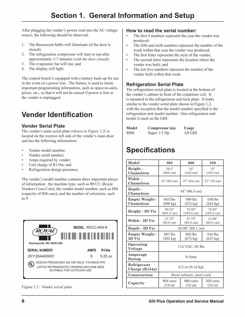
Vender IdentificationVender Serial PlateThe vender’s main serial plate (shown in Figure 1.2) is located on the exterior left side of the vender’s main door and has the following information:
• Vender model number;• Vender serial number;• Amps required by vender;• Unit charge of R134a; and• Refrigeration design pressures.
The vender’s model number contains three important pieces of information: the machine type, such as RVCC (Royal Vendors Coca-Cola); the vender model number, such as 804 (capacity of 804 cans); and the number of selections, such as 9.
How to read the serial number:• The first 4 numbers represent the year the vender was
produced;• The fifth and sixth numbers represent the number of the
week within that year the vender was produced;• The first letter represents the style of the vender;• The second letter represents the location where the
vender was built; and• The last five numbers represent the number of the
vender built within that week.
Refrigeration Serial PlateThe refrigeration serial plate is located at the bottom of the vender’s cabinet in front of the condenser coil. It is mounted to the refrigeration unit kick plate. It looks similar to the vender serial plate shown in Figure 1.2, with the exception that the model number specified is the refrigeration unit model number. One refrigeration unit model is used on the GIII:
Model Compressor size Usage8000 Super 1/3 Hp All GIII
Specifications
201126AA00001 9 5.25 ozSERIAL NUMBER AMPS R134a
RVCC-804-8MODEL
Kearneysville, WV 25430 USA
DESIGN PRESSURES 300 HS/156LS 115V/60HZ/1PHLISTED REFRIGERATED VENDING MACHINE 66E9
SUITABLE FOR OUTDOOR USE
Figure 1.2: Vender serial plate.
Model 804 660 550Height - Chameleon
79.5”(202 cm)
72”(183 cm)
72”(183 cm)
Width - Chameleon 37” (94 cm) 37” (94 cm) 31” (79 cm)
Depth - Chameleon 34” (86.5 cm)
Empty Weight - Chameleon
653 lbs (296 kg)
599 lbs (272 kg)
536 lbs (243 kg)
Height - 3D Vis 80.33”(204.0 cm)
72.83”(185.0 cm)
72.83”(185.0 cm)
Width - 3D Vis 37.75”(95.9 cm)
37.75”(95.9 cm)
31.68”(80.5 cm)
Depth - 3D Vis 35.09” (89.1 cm)Empty Weight - 3D Vis
667 lbs (303 kg)
602 lbs (273 kg)
544 lbs (247 kg)
Operating Voltage 115 VAC, 60 Hz
Amperage Rating 9 Amp
Refrigerant Charge (R134a) 6.5 oz (0.18 kg)
Construction Steel cabinet, steel rack
Capacity 804 cans (12 oz)
660 cans (12 oz)
550 cans (12 oz)

GIII Plus Operation and Service Manual 9
Section 2. Vender Component Explanation
Vender Component ExplanationVender Control Board (including pinouts)The control board is responsible for most vender operations. It is located in the upper left corner of the inside of the door. The control board is protected by a cover. Removing this cover will expose the control boad, along with all wiring connections to the board.
IDENTIFICATION: The GIII KO control board can be easily identified by a Royal Vendors part number decal on the board’s capacitor.
OPERATION REQUIREMENTS: The control board requires approximately 24 volts AC from the low voltage transformer (described later in this section). This will allow the control board to function and to supply power to all the vender’s components listed below.
OPERATION: Upon receiving the appropriate voltage from the transformer, the control board will issue information to some components, receive information from some components, and communicate both ways with some components.
• The control board issues instructions (and / or voltage) to: - Display - Refrigeration relay.
• The control board receives information (and / or voltage) from: - Select switches (logic level) - Door switch (logic level) - Delivery chute sensor - Temperature sensor.
• The control board communicates both ways with: - Vend motor - Coin mechanism - Bill validator (optional) - Card reader (optional) - Hand-held computer (optional).
CONTROL BOARD PINOUTS: The GIII KO control board has several electrical pinouts, a setup mode button, a delivery sensor adjustment trimpot, a delivery sensor adjustment indicator lamp, and various other electronic components (all of which have designated position codes). The following section outlines all the control board’s pinouts.
The word key refers to the small plastic insert plugged into a position of the connector. The purpose of the key is to prevent connecting the harnessing backwards or upside-down. The keyed position is a blank position within the pinout (no pin) in which a key is inserted. Some pinouts may have several blank positions with a key plugged into one or more of the positions. You can use the key to determine which end of the pinout is Pin 1.
Precautions to take when working with the control boardAs with any printed circuit board, our electronics are very sensitive to Electrostatic Discharge (ESD). Simply walking across a tile or carpeted floor can generate a range of 30,000 to 50,000 volts of electricity. One ESD can be enough to seriously damage your control board or at least weaken it enough that erratic problems could occur in the future. Even a discharge surge under 100 to 200 volts is enough to create problems within the circuitry of the electronics. It is advised when storing the electronics that they be kept in anti-static bags, even if the electronics are thought to be defective. If a control board is thought to be defective and is really not, it soon will be after being charged with ESD. The ideal prevention against ESD is to use anti-static conductive wrist straps which earth you to the machine before touching the electronic boards. If it is not possible to use these, at least earth yourself before handling the electronic boards. Whatever method you use, always handle the electronic boards by the edges. Be careful not to touch the components on the control board.
GIII Plus Operation and Service Manual10
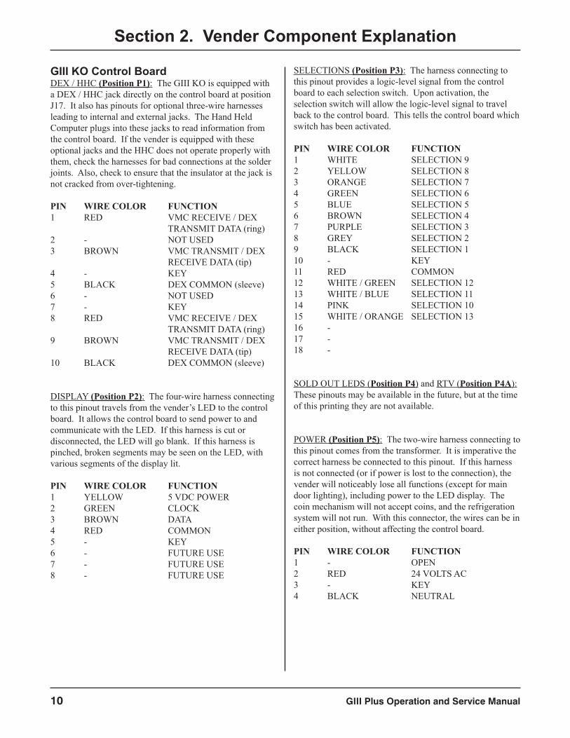
GIII KO Control BoardDEX / HHC (Position P1): The GIII KO is equipped with a DEX / HHC jack directly on the control board at position J17. It also has pinouts for optional three-wire harnesses leading to internal and external jacks. The Hand Held Computer plugs into these jacks to read information from the control board. If the vender is equipped with these optional jacks and the HHC does not operate properly with them, check the harnesses for bad connections at the solder joints. Also, check to ensure that the insulator at the jack is not cracked from over-tightening.
PIN WIRE COLOR FUNCTION1 RED VMC RECEIVE / DEX TRANSMIT DATA (ring)2 - NOT USED 3 BROWN VMC TRANSMIT / DEX RECEIVE DATA (tip) 4 - KEY5 BLACK DEX COMMON (sleeve)6 - NOT USED7 - KEY8 RED VMC RECEIVE / DEX TRANSMIT DATA (ring)9 BROWN VMC TRANSMIT / DEX RECEIVE DATA (tip)10 BLACK DEX COMMON (sleeve)
DISPLAY (Position P2): The four-wire harness connecting to this pinout travels from the vender’s LED to the control board. It allows the control board to send power to and communicate with the LED. If this harness is cut or disconnected, the LED will go blank. If this harness is pinched, broken segments may be seen on the LED, with various segments of the display lit.
PIN WIRE COLOR FUNCTION1 YELLOW 5 VDC POWER2 GREEN CLOCK3 BROWN DATA4 RED COMMON5 - KEY6 - FUTURE USE7 - FUTURE USE8 - FUTURE USE
SELECTIONS (Position P3): The harness connecting to this pinout provides a logic-level signal from the control board to each selection switch. Upon activation, the selection switch will allow the logic-level signal to travel back to the control board. This tells the control board which switch has been activated.
PIN WIRE COLOR FUNCTION1 WHITE SELECTION 92 YELLOW SELECTION 83 ORANGE SELECTION 74 GREEN SELECTION 65 BLUE SELECTION 56 BROWN SELECTION 47 PURPLE SELECTION 38 GREY SELECTION 29 BLACK SELECTION 110 - KEY11 RED COMMON12 WHITE / GREEN SELECTION 1213 WHITE / BLUE SELECTION 1114 PINK SELECTION 1015 WHITE / ORANGE SELECTION 1316 - 17 - 18 -
SOLD OUT LEDS (Position P4) and RTV (Position P4A): These pinouts may be available in the future, but at the time of this printing they are not available.
POWER (Position P5): The two-wire harness connecting to this pinout comes from the transformer. It is imperative the correct harness be connected to this pinout. If this harness is not connected (or if power is lost to the connection), the vender will noticeably lose all functions (except for main door lighting), including power to the LED display. The coin mechanism will not accept coins, and the refrigeration system will not run. With this connector, the wires can be in either position, without affecting the control board.
PIN WIRE COLOR FUNCTION1 - OPEN2 RED 24 VOLTS AC3 - KEY4 BLACK NEUTRAL
Section 2. Vender Component Explanation
GIII Plus Operation and Service Manual 11
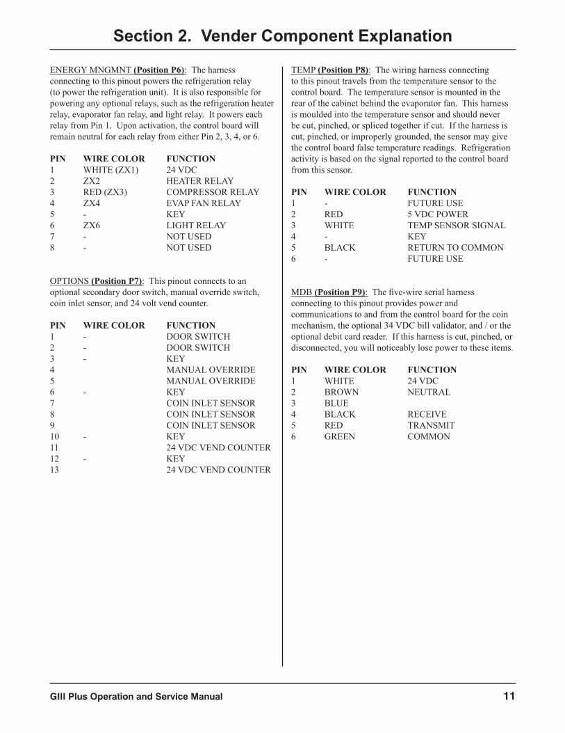
ENERGY MNGMNT (Position P6): The harness connecting to this pinout powers the refrigeration relay (to power the refrigeration unit). It is also responsible for powering any optional relays, such as the refrigeration heater relay, evaporator fan relay, and light relay. It powers each relay from Pin 1. Upon activation, the control board will remain neutral for each relay from either Pin 2, 3, 4, or 6.
PIN WIRE COLOR FUNCTION1 WHITE (ZX1) 24 VDC2 ZX2 HEATER RELAY3 RED (ZX3) COMPRESSOR RELAY4 ZX4 EVAP FAN RELAY5 - KEY6 ZX6 LIGHT RELAY7 - NOT USED8 - NOT USED
OPTIONS (Position P7): This pinout connects to an optional secondary door switch, manual override switch, coin inlet sensor, and 24 volt vend counter.
PIN WIRE COLOR FUNCTION1 - DOOR SWITCH2 - DOOR SWITCH3 - KEY4 MANUAL OVERRIDE5 MANUAL OVERRIDE6 - KEY7 COIN INLET SENSOR8 COIN INLET SENSOR9 COIN INLET SENSOR10 - KEY11 24 VDC VEND COUNTER12 - KEY13 24 VDC VEND COUNTER
TEMP (Position P8): The wiring harness connecting to this pinout travels from the temperature sensor to the control board. The temperature sensor is mounted in the rear of the cabinet behind the evaporator fan. This harness is moulded into the temperature sensor and should never be cut, pinched, or spliced together if cut. If the harness is cut, pinched, or improperly grounded, the sensor may give the control board false temperature readings. Refrigeration activity is based on the signal reported to the control board from this sensor.
PIN WIRE COLOR FUNCTION1 - FUTURE USE2 RED 5 VDC POWER3 WHITE TEMP SENSOR SIGNAL4 - KEY5 BLACK RETURN TO COMMON6 - FUTURE USE
MDB (Position P9): The five-wire serial harness connecting to this pinout provides power and communications to and from the control board for the coin mechanism, the optional 34 VDC bill validator, and / or the optional debit card reader. If this harness is cut, pinched, or disconnected, you will noticeably lose power to these items.
PIN WIRE COLOR FUNCTION1 WHITE 24 VDC2 BROWN NEUTRAL3 BLUE 4 BLACK RECEIVE5 RED TRANSMIT6 GREEN COMMON
Section 2. Vender Component Explanation
GIII Plus Operation and Service Manual12
Section 2. Vender Component Explanation
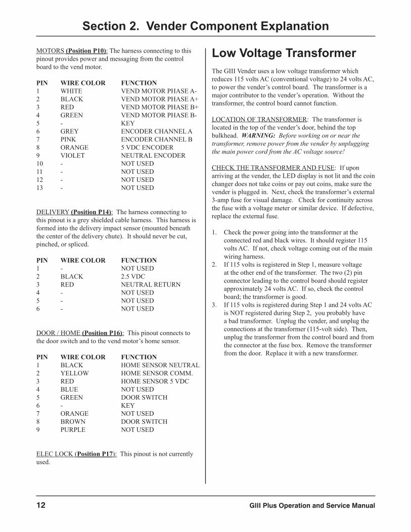
MOTORS (Position P10): The harness connecting to this pinout provides power and messaging from the control board to the vend motor.
PIN WIRE COLOR FUNCTION1 WHITE VEND MOTOR PHASE A-2 BLACK VEND MOTOR PHASE A+3 RED VEND MOTOR PHASE B+4 GREEN VEND MOTOR PHASE B-5 - KEY6 GREY ENCODER CHANNEL A7 PINK ENCODER CHANNEL B8 ORANGE 5 VDC ENCODER9 VIOLET NEUTRAL ENCODER10 - NOT USED11 - NOT USED12 - NOT USED13 - NOT USED
DELIVERY (Position P14): The harness connecting to this pinout is a grey shielded cable harness. This harness is formed into the delivery impact sensor (mounted beneath the center of the delivery chute). It should never be cut, pinched, or spliced.
PIN WIRE COLOR FUNCTION1 - NOT USED2 BLACK 2.5 VDC3 RED NEUTRAL RETURN4 - NOT USED5 - NOT USED6 - NOT USED
DOOR / HOME (Position P16): This pinout connects to the door switch and to the vend motor’s home sensor.
PIN WIRE COLOR FUNCTION1 BLACK HOME SENSOR NEUTRAL2 YELLOW HOME SENSOR COMM.3 RED HOME SENSOR 5 VDC4 BLUE NOT USED5 GREEN DOOR SWITCH6 - KEY7 ORANGE NOT USED8 BROWN DOOR SWITCH9 PURPLE NOT USED
ELEC LOCK (Position P17): This pinout is not currently used.
Low Voltage TransformerThe GIII Vender uses a low voltage transformer which reduces 115 volts AC (conventional voltage) to 24 volts AC, to power the vender’s control board. The transformer is a major contributor to the vender’s operation. Without the transformer, the control board cannot function.
LOCATION OF TRANSFORMER: The transformer is located in the top of the vender’s door, behind the top bulkhead. WARNING: Before working on or near the transformer, remove power from the vender by unplugging the main power cord from the AC voltage source!
CHECK THE TRANSFORMER AND FUSE: If upon arriving at the vender, the LED display is not lit and the coin changer does not take coins or pay out coins, make sure the vender is plugged in. Next, check the transformer’s external 3-amp fuse for visual damage. Check for continuity across the fuse with a voltage meter or similar device. If defective, replace the external fuse.
1. Check the power going into the transformer at the connected red and black wires. It should register 115 volts AC. If not, check voltage coming out of the main wiring harness.
2. If 115 volts is registered in Step 1, measure voltage at the other end of the transformer. The two (2) pin connector leading to the control board should register approximately 24 volts AC. If so, check the control board; the transformer is good.
3. If 115 volts is registered during Step 1 and 24 volts AC is NOT registered during Step 2, you probably have a bad transformer. Unplug the vender, and unplug the connections at the transformer (115-volt side). Then, unplug the transformer from the control board and from the connector at the fuse box. Remove the transformer from the door. Replace it with a new transformer.
GIII Plus Operation and Service Manual 13
Section 2. Vender Component Explanation
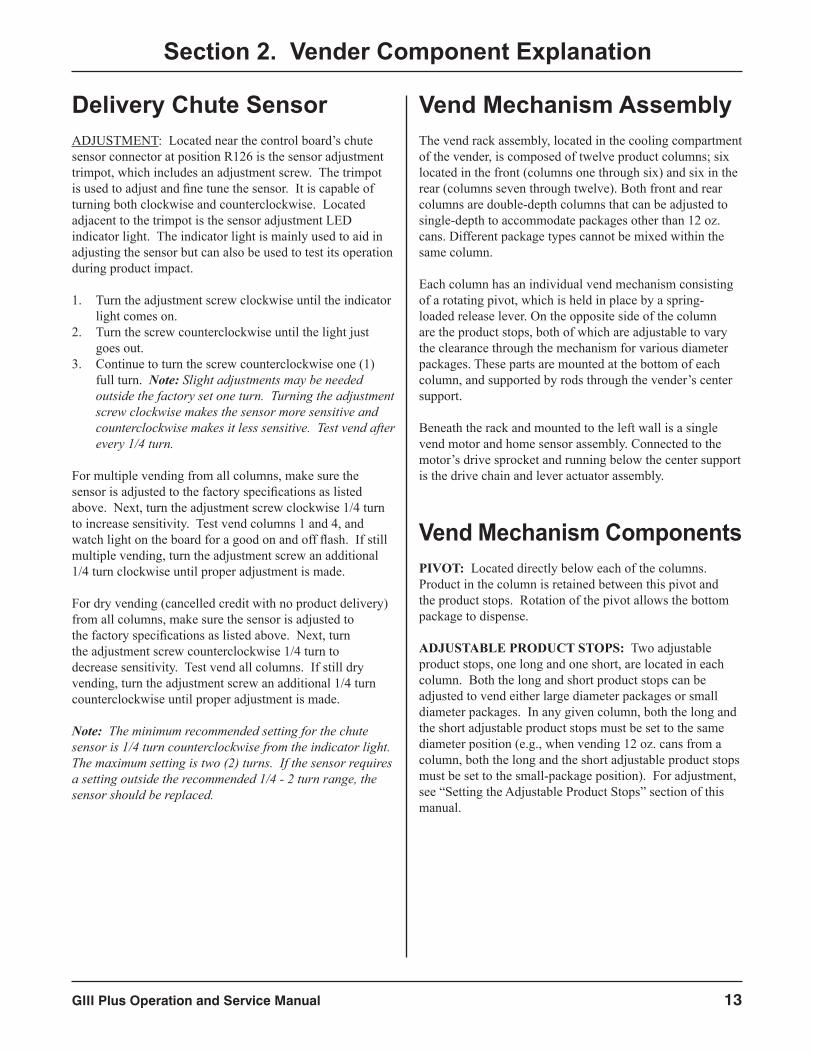
Delivery Chute SensorADJUSTMENT: Located near the control board’s chute sensor connector at position R126 is the sensor adjustment trimpot, which includes an adjustment screw. The trimpot is used to adjust and fine tune the sensor. It is capable of turning both clockwise and counterclockwise. Located adjacent to the trimpot is the sensor adjustment LED indicator light. The indicator light is mainly used to aid in adjusting the sensor but can also be used to test its operation during product impact.
1. Turn the adjustment screw clockwise until the indicator light comes on.
2. Turn the screw counterclockwise until the light just goes out.
3. Continue to turn the screw counterclockwise one (1) full turn. Note: Slight adjustments may be needed outside the factory set one turn. Turning the adjustment screw clockwise makes the sensor more sensitive and counterclockwise makes it less sensitive. Test vend after every 1/4 turn.
For multiple vending from all columns, make sure the sensor is adjusted to the factory specifications as listed above. Next, turn the adjustment screw clockwise 1/4 turn to increase sensitivity. Test vend columns 1 and 4, and watch light on the board for a good on and off flash. If still multiple vending, turn the adjustment screw an additional 1/4 turn clockwise until proper adjustment is made.
For dry vending (cancelled credit with no product delivery) from all columns, make sure the sensor is adjusted to the factory specifications as listed above. Next, turn the adjustment screw counterclockwise 1/4 turn to decrease sensitivity. Test vend all columns. If still dry vending, turn the adjustment screw an additional 1/4 turn counterclockwise until proper adjustment is made.
Note: The minimum recommended setting for the chute sensor is 1/4 turn counterclockwise from the indicator light. The maximum setting is two (2) turns. If the sensor requires a setting outside the recommended 1/4 - 2 turn range, the sensor should be replaced.
Vend Mechanism AssemblyThe vend rack assembly, located in the cooling compartment of the vender, is composed of twelve product columns; six located in the front (columns one through six) and six in the rear (columns seven through twelve). Both front and rear columns are double-depth columns that can be adjusted to single-depth to accommodate packages other than 12 oz. cans. Different package types cannot be mixed within the same column.
Each column has an individual vend mechanism consisting of a rotating pivot, which is held in place by a spring-loaded release lever. On the opposite side of the column are the product stops, both of which are adjustable to vary the clearance through the mechanism for various diameter packages. These parts are mounted at the bottom of each column, and supported by rods through the vender’s center support.
Beneath the rack and mounted to the left wall is a single vend motor and home sensor assembly. Connected to the motor’s drive sprocket and running below the center support is the drive chain and lever actuator assembly.
Vend Mechanism ComponentsPIVOT: Located directly below each of the columns. Product in the column is retained between this pivot and the product stops. Rotation of the pivot allows the bottom package to dispense.
ADJUSTABLE PRODUCT STOPS: Two adjustable product stops, one long and one short, are located in each column. Both the long and short product stops can be adjusted to vend either large diameter packages or small diameter packages. In any given column, both the long and the short adjustable product stops must be set to the same diameter position (e.g., when vending 12 oz. cans from a column, both the long and the short adjustable product stops must be set to the small-package position). For adjustment, see “Setting the Adjustable Product Stops” section of this manual.
GIII Plus Operation and Service Manual14
Section 2. Vender Component Explanation
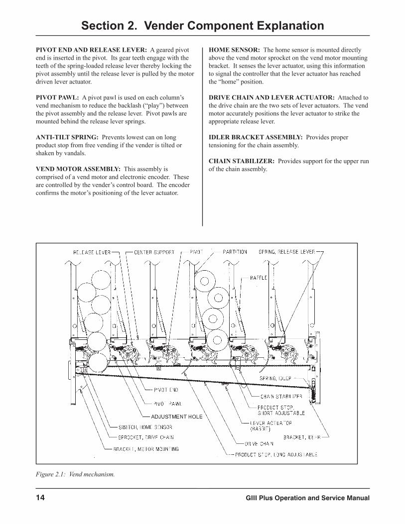
PIVOT END AND RELEASE LEVER: A geared pivot end is inserted in the pivot. Its gear teeth engage with the teeth of the spring-loaded release lever thereby locking the pivot assembly until the release lever is pulled by the motor driven lever actuator.
PIVOT PAWL: A pivot pawl is used on each column’s vend mechanism to reduce the backlash (“play”) between the pivot assembly and the release lever. Pivot pawls are mounted behind the release lever springs.
ANTI-TILT SPRING: Prevents lowest can on long product stop from free vending if the vender is tilted or shaken by vandals.
VEND MOTOR ASSEMBLY: This assembly is comprised of a vend motor and electronic encoder. These are controlled by the vender’s control board. The encoder confirms the motor’s positioning of the lever actuator.
HOME SENSOR: The home sensor is mounted directly above the vend motor sprocket on the vend motor mounting bracket. It senses the lever actuator, using this information to signal the controller that the lever actuator has reached the “home” position.
DRIVE CHAIN AND LEVER ACTUATOR: Attached to the drive chain are the two sets of lever actuators. The vend motor accurately positions the lever actuator to strike the appropriate release lever.
IDLER BRACKET ASSEMBLY: Provides proper tensioning for the chain assembly.
CHAIN STABILIZER: Provides support for the upper run of the chain assembly.
Figure 2.1: Vend mechanism.
GIII Plus Operation and Service Manual 15
Section 2. Vender Component Explanation
Refrigeration SystemThe vender’s refrigeration system is responsible for the cooling of the cabinet and the products loaded within it. The refrigeration system comes as a completely sealed unit and should never be cut or tapped into, or the warranty will be voided.
Operation RequirementsThe refrigeration system requires 115 volts AC from the main wiring harness for it to operate. The main wiring harness will get its voltage for the unit from the refrigeration relay.
Refrigeration ComponentsThe refrigeration system is a sealed system. Described in this section are explanations of the refrigeration system’s major components.
Compressor - The compressor is a hermetically-sealed unit located beneath (outside) the cooling compartment. The compressor is a pump, driven by the compressor motor which draws low-pressure vapor (refrigerant) from the evaporator coil, compresses it, and forces it into the condenser under high pressure. The motor is started and controlled by the refrigeration relay.
Condenser - The condenser is located beneath (outside) the cooling compartment next to the compressor. It can be seen from the front with the door open. The condenser removes heat from the high-pressure vapor discharged from the
compressor and condenses it to a high-pressure liquid. The condenser and evaporator coils have aluminum fins attached to effectively increase heat exchange surfaces.
Starting Relay - The starting relay is mounted on the side of the compressor housing. The compressor motor has two windings (start winding and run winding). To give the motor torque when it first starts, the starting relay switches in the additional start winding. After the motor gets up to speed, the relay opens the start winding and the motor continues using only the run winding.
Thermal Overload - The thermal overload is a heat-sensitive device mounted on the side of the compressor housing. If the compressor motor gets too hot or draws an excessive amount of current, the thermal overload will open, breaking the circuit to the compressor. After the compressor cools to a safe operating temperature, the thermal overload will close, allowing the compressor and condenser fan motors to restart.
Condenser Fan and Motor - The condenser fan and motor, located beneath the cooling department, are a forced-air device using outside ambient air to cool the surface of the condenser coil. The condenser fan and motor run while the compressor operates.
Evaporator Coil - The evaporator coil is located in the cooling compartment. As low pressure liquid passes through the evaporator coil, it absorbs and removes heat from the compartment as it changes to vapor. The condenser and evaporator coil have aluminum fins attached
to effectively increase their heat exchange surfaces.
Evaporator Fan and Motor - The evaporator fan and motor are a forced-air device circulating air throughout the cooling compartment and over the heat exchange surface of the evaporator coil.
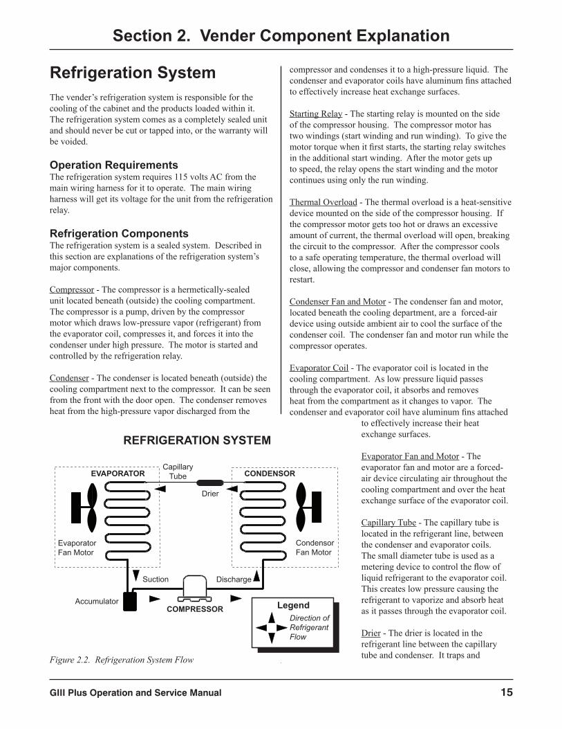
Capillary Tube - The capillary tube is located in the refrigerant line, between the condenser and evaporator coils. The small diameter tube is used as a metering device to control the flow of liquid refrigerant to the evaporator coil. This creates low pressure causing the refrigerant to vaporize and absorb heat as it passes through the evaporator coil.
Drier - The drier is located in the refrigerant line between the capillary tube and condenser. It traps and
COMPRESSOR
DischargeSuction
CondensorFan Motor
EvaporatorFan Motor
CONDENSOREVAPORATOR
Drier
REFRIGERATION SYSTEM
LegendDirection ofRefrigerantFlow
Accumulator
CapillaryTube
Figure 2.2. Refrigeration System Flow
GIII Plus Operation and Service Manual16
removes moisture from the refrigeration system while allowing oil and refrigerant to pass through the system.
Accumulator - The accumulator is located in the refrigerant line between the evaporator coil and the compressor. The accumulator traps any liquid refrigerant which did not vaporize before it reaches the compressor.
Refrigeration Relay - The refrigeration relay is located in the lower left section of the vender’s cabinet near the main wiring harness. The refrigeration relay is responsible for powering the compressor and condenser fan motors. The refrigeration relay consists of a coil powered by the control board (24 VDC) and a switch. When the control board completes the circuit to the refrigeration relay, the relay will energize, closing the contact between the common and the normally-open positions. When this happens, power (115 VAC) travels from the refrigeration relay to the main wiring harness for the refrigeration unit.
Refrigeration Cycle1. The rising temperature in the cooling compartment is
reported to the control board through the temperature sensor.
2. The control board registers the current temperature inside the vender’s cabinet. When it rises equal to or above the pre-programmed cut-in temperature, the control board will complete the circuit to the refrigeration relay to energize its coil.
3. The refrigeration relay coil closes the contact between the common and normally-open positions, allowing 115 volts to travel to the main wiring harness to start the compressor.
4. The compressor circulates refrigerant throughout the system by pulling low-pressure refrigerant vapor from the evaporator coil, compressing it, and forcing it into the condenser. The condenser, aided by the condenser fan motor, removes heat from the refrigerant as it flows through the condenser and releases it to the outside environment. The dropping of the refrigerant temperature changes the vapor to liquid.
5. The evaporator coil allows the liquid refrigerant to absorb heat from the cooling compartment as it evaporates in the coil.
6. The falling temperature in the cooling compartment is caused by the continual circulation of refrigerant through the system, removing heat from the cooling compartment and transporting it to the outside environment. When the temperature drops, the temperature sensor reports this to the vender’s control board.
7. When the temperature drops below the preset cut-out temperature, the control board will disable the refrigeration relay, thus killing power to the refrigeration unit.
Testing the Refrigeration System1. The sealed refrigeration unit can be tested by unplugging
it from the top of the main wiring harness and plugging it directly into a power source. If the unit still does not operate, a problem exists within the sealed unit.
2. If the sealed unit runs when plugged into an external power source, the problem more than likely lies between the control board, the refrigeration relay, and the main wiring harness.
Section 2. Vender Component Explanation
WARNINGELECTROCUTION HAZARD
When plugging the refrigeration unit directly into a wall outlet or other external electrical source, the refrigeration unit MUST remain in the vender for proper grounding. If the unit is removed from the
vender, an electrocution hazard exists.
BallastThe ballast acts as a transformer to convert conventional voltage (115 VAC) to a higher voltage required to energize the vender’s fluorescent lights (upwards of 600 VAC). The ballast is located inside the vender’s door. To remove the ballast from the door, use a Phillips screwdriver to remove the screws that mount the ballast to the door chassis.
WARNING: Before removing the ballast tray, remove power from the vender by unplugging the main power cord from the AC voltage source (wall outlet)!
Note: Power to the ballast is controlled by a relay, which is in turn controlled by the logic of the vender’s control board. See SECTION 3: VENDER PROGRAMMING for information on energizing this relay through the service menu for troubleshooting purposes.
GIII Plus Operation and Service Manual 17
Vender ProgrammingIntroduction to Four-button ProgrammingIt is very important that your vender is programmed properly. All programming of the vender options is done in the Service Mode. To enter the Service Mode, open the vender door, and press and release the service mode button that is located on the control board.
The first four selection switches are used to navigate through the service routines as follows:
Button Meaning Usage1 EXIT Escape, cancel, exit2 UP Increase, next, up3 DOWN Decrease, previous, down4 ENTER Enter, accept, save
The controller will automatically return to the Sales Mode if:
• No response from the selection switches is received for approximately five minutes;
• The service mode button is pressed a second time;• The Return to Sales mode is activated; or• The door is actually closed.
If credit exists, the credit amount will be displayed after returning to the Sales Mode.
EMS SoftwareBy capturing and remembering when sales are made over time, the machine’s lighting and refrigeration systems can be powered down at periods of inactivity. This is made possible by the addition of the EMS software.
What does the Delay (“dLAy”) setting represent in the Lighting Control and Refrigeration Control Modes? The delay can be set anywhere from 0 minutes all the way up to 995 minutes. As an example, we will use a setting of 30 minutes for the Lighting Control delay and 90 minutes for the Refrigeration Control delay. This means, at these settings, if Lighting Control and Refrigeration Control are both Enabled to 2, the lights on the vender will come on 30 minutes prior to learned customer activity and turn off 30
Section 3. Vender Programming
after customer activity, based on what the EMS software has learned over a period of time. With the Refrigeration Control, the “dLAy” (Delay) value is only used when exiting conservation mode; thus, that the refrigeration system will turn on 90 minutes prior to learned customer activity.
Note that in all venders with EMS Software, it is imperative that the time / date be set correctly in the Internal (Service) Menu. Incorrect time / date in the control board will cause a skewing of the pattern determined by the EMS Software, resulting in improper performance of the machine to the anticipated pattern.
Resetting the EMS time blocksTo reset the time blocks, simply change Lighting Control and Refrigeration Control so that both are both Enabled to 1. After changing them to 1, exit out of the Service Menu. Then, enter back into the menu and Enable Lighting Control and Refrigeration Control to 2.
Menu SystemWhen programming, you must first use the programming buttons listed above to maneuver through menus and sub-menus before you will be allowed to accomplish your task. Each menu consists of various items, or modes, such as Price Setting Mode or Space to Sales Programming Mode. There are two menus:
1. INTERNAL (Service) MENU - This menu is available only with the vender’s door open. It is accessed upon pressing the control board’s mode button.
2. EXTERNAL MENU - This menu is available by entering the proper external password with the vender’s door closed. (See Password Preview Mode in the following section.) From this menu, cash / sales counts and vender errors can be read (but not cleared).
Note: Programming flowchart located in rear of manual.
GIII Plus Operation and Service Manual18
Section 3. Vender Programming
Internal (Service) MenuOpening the vender’s main door and pressing the control board’s service mode button will allow entry into the Internal (Service) Menu. This section outlines all the menu items.
ERROR CODE DISPLAY MODEIf <enter> is pressed at the “Eror” prompt, the controller will enter the error display
mode. If no errors have occurred since the last error reset, the display will show “nonE.” If an error has been detected since the last error reset, the display will show the first summary error code that has occurred, such as “UEnd,” which would indicate a vend error. Pressing <up> or <down> will allow you to cycle through all of the summary error codes that are present. Pressing <enter> at the displayed summary error code will allow you to view the detailed error codes beneath the summary error heading (see below). Pressing <up> or <down> at this point will allow you to cycle through all of the detailed error codes that are present beneath the summary error code. If the <exit> button is pressed anytime during this operation, the controller will return to the “Eror” prompt. Press the <up> button to proceed to the next prompt, “CPO.”
If <enter> is pressed and held for two seconds during the display of any detailed error code, that error will be cleared. If other errors exist that fall under the currently accessed detail type, the next error would be displayed. If no other errors of the current type exist, the next error summary code will be displayed, or “nonE” will be displayed if no other errors exist.
The error summary codes and their corresponding detailed error codes are as follows:
• Ctrl (Control System Error) By pressing <enter> at the “Ctrl” prompt, the controller
will display:1. “dS,” indicating the door switch has been open for
more than an hour;2. “rAn,” indicating the machine setup information
has been corrupted;3. “ACLo,” indicating that the average rectified
voltage was under 20 VDC for more than 30 seconds;
4. “SF” indicating one of the credit peripherals has introduced an incompatible scaling factor;
5. “IS,” indicating the machine’s coin inlet sensor has been blocked for more than a minute (note: this is an optional component not installed on all venders); or
6. “Ib,” indicating two coins were sensed at the inlet sensor but didn’t make it to the changer within 10 seconds.
After taking corrective action to manually fix the “Ctrl” errors, the errors may be cleared electronically via a hand held device or through the service mode by pressing <enter> for two seconds.
• SEL (Selection Switch Error) By pressing <enter> at the “SEL” prompt, the controller
will display “SSXX,” where “XX” indicates the first selection switch that has been determined to be closed for more than 15 seconds. If there is a selection switch error, navigation of the service menu may not be possible. This error can only be cleared by manually correcting the problem.
• CHAr (Coin Changer Error) By pressing <enter> at the “CHAr” prompt, the
controller will display either:
1. “CC,” indicating no changer communications for more than 2 seconds;
2. “tS,” indicating a tube sensor error;3. “IC,” indicating no coins sensed by acceptor for
over 96 hours:4. “tJXX,” indicating a tube jam error for coin type
XX;5. “CrCH,” indicating a changer ROM checksum
error;6. “EE” indicating more than 255 escrow attempts
since the last coin was accepted;7. “nJ,” indicating a coin jam; or8. “LA,” indicating a low acceptance rate (more than
20% of the last 255 coins were slugs).
The “CC” error will be cleared when proper communications are re-established. After taking corrective action to manually fix the other “CHAr” problems, the errors may be cleared electronically via a hand held device or through the service mode by pressing <enter> for two seconds.
Eror
GIII Plus Operation and Service Manual 19
Section 3. Vender Programming
• bUAL (Bill Validator Error) By pressing <enter> at the “bUAL” prompt, the
controller will display either:
1. “bC,” indicating no bill validator communications for more than 5 seconds;
2. “bFuL,” indicating a full bill stacker;3. “bILL,” indicating a defective motor;4. “bJ,” indicating a bill jam error;5. “brCH,” indicating a bill acceptor ROM check sum
error;6. “bOPn,” indicating an open cash box; or7. “bS,” indicating a bill sensor error.
The “bC” error will be cleared when proper communications are re-established. After taking corrective action to manually fix the other “bUAL” problems, the errors may be cleared electronically via a hand held device or through the service mode by pressing <enter> for two seconds.
• Crdr (Card Reader Error) By pressing <enter> at the “Crdr” prompt, the controller
will display either:
1. “CrC,” indicating no card reader communications for more than 5 seconds; or
2. “CrXY,” indicating that a particular type of card reader malfunction occurred where “XY” indicates the error type.
The “CrC” error will be cleared when proper communications are re-established. The “CrXY” errors may be reset via the hand held device or through the service mode by pressing <enter> for two seconds.
• UEnd (Vend Mechanism Error) By pressing <enter> at the “UEnd” prompt, the
controller will display either:
1. “CJXX,” indicating a jam in column XX; or2. “CS,” indicating that the chute sensor is active for
more than 5 minutes.
After taking corrective action to manually fix the “UEnd” errors, the errors may be cleared electronically via a hand held device or through the service mode by pressing <enter> for two seconds.
• StS (Space to Sales Error) By pressing <enter> at the “StS” prompt, the controller
will display “UAXX,” indicating that column XX is unassigned. These errors are cleared when new space to sales programming resolves the errors. (Note: When an unassigned button is selected in the sales mode, the display will show “Sold Out.”)
• rFrG (Refrigeration Error) By pressing <enter> at the “rFrG” prompt, the
controller will display either:
1. “SEnS,” indicating an unplugged temperature sensor error;
2. “COLd,” indicating temperatures 1.5º C or more below the compressor cut-out setting;
3. “HOt,” indicating temperatures 1.5º C or more above the compressor cut-in setting;
4. “CnPr,” indicating that the compressor is not cooling at 0.5º C per hour or better while on; or
5. “Htr,” indicating that the heating system is not heating at 0.5º C per hour or better while on.
The “SEnS” error will be cleared if the sensor is detected. The “COLd” error will be cleared when the temperature rises above the cut-out limit. The “HOt” error will be cleared when the temperature falls below the cut-in limit. The “CnPr” error will be cleared when the system cools at 0.5º C per hour or better. The “Htr” error will be cleared when the system heats at 0.5º C per hour or better.
GIII Plus Operation and Service Manual20
Section 3. Vender Programming
COIN PAY OUT MODEIf <enter> is pressed at the “CPO” prompt the controller will enter the coin payout
mode by displaying the lowest coin value that can be paid out. Pressing <up> will increase the display to show the next highest coin value, pressing <down> will decrease the display to show the next lowest coin value or wrap around. Pressing <enter> when a particular coin value is displayed will pay out the displayed coin type at half-second intervals until the button is released. All coins dispensed in this mode are counted in the MIS tube counts and the manual dispense mode counters. Pressing <exit> while a coin value is displayed will return the controller to the “CPO” prompt. Use <up> to proceed to the next prompt, “tUFL.”
TUBE FILL MODEIf <enter> is pressed at the “tUFL” prompt the controller will enter the coin tube fill
mode. In this mode, you are allowed to deposit any coin that is routed to a tube. This provides total accountability. The tube inventory level for the deposited coin will be displayed after the coin is accepted. If a tube full status is detected, that coin will no longer be accepted. During this entire operation, MIS tube counts and manual fill mode counters will be updated accordingly. If <exit> is pressed at any time during this operation, the controller will return to the “tUFL” prompt. Use <up> to proceed to the next prompt, “rPO.”
RECYCLER PAY OUT MODEIf <enter> is pressed at the “rPO” prompt, the controller will enter the bill payout mode by displaying the lowest bill value
that can be paid out. Pressing <up> will increase the display to show the next higher bill value, if any; pressing <down> will decrease the display to show the next lower bill value or wrap around. Pressing <enter> when a particular bill value is displayed will pay out the displayed bill type. All bills dispensed in this mode are counted in the MIS manual dispense mode counters. Pressing <exit> while a bill value is displayed will return the controller to the “rPO” prompt. Use <up> to proceed to the next prompt, “tESt.”
TEST MODESIf <enter> is pressed at the “tESt” prompt, the controller will enter the test mode by
displaying “UEnd”. Using <up> or <down> will allow you to cycle through the available tests. If <exit> is pressed at any time, the controller will return to the “tESt” prompt. Use <up> to proceed to the next prompt, “PASS.”
• UEnd (Column Test Vend) Pressing <enter> at the “UEnd” prompt will cause the
controller to enter the column vend test routine. This routine will allow you to test each column motor. Upon entry into this routine, the display will show “CO 1,” indicating that a test vend from column 1 may be initiated. <Up> or <down> can be pressed to cycle through the available columns. Activation of <enter> at a displayed column will initiate a test vend on that column. Vends made while in this routine will not be added to the “SALE” mode totals. If <exit> is pressed at any time when “CONN” is displayed, the controller will return to the “Test Vend” prompt.
• SL (Select Switch Test) If <enter> is pressed at the “SL” prompt, the controller
will enter the selection switch test mode. The display will show “SL4,” which indicates that the fourth selection switch was pressed last. When any selection switch is pressed, it will be represented by the numbers shown after “SL.” The last selection switch pressed will remain on the display until the service mode timer expires or the <exit> button is pressed for two seconds. This will return the controller to the “SL” prompt. Press <up> to proceed to the next prompt, “SO.”
• SO (Sold Out Test) Pressing <enter> at the “SO” prompt will cause the
controller to enter the sold out test routine. The display will show “C1X,” which represents column 1. If the column number is followed by “0,” the column is not sold out; if the column number is followed by “1,” the column is sold out. Pressing <up> or <down> will allow you to cycle through all the available columns. Pressing <enter> has no action. Pressing <exit> will return the controller to the “SO” prompt. Press <up> to proceed to the next prompt, “dSP.”
CPO
tUFL
tESt
rPO
GIII Plus Operation and Service Manual 21
Section 3. Vender Programming
• dSP (Display Test) Pressing <enter> at the “dSP” prompt will cause the
controller to enter the display test routine. This routine allows you to test the display. Upon entry into this routine, all segments of the display, the correct-change only light, and the sold-out light will run a diagnostic test until a timer expires or <exit> is pressed. This will return the controller to the “dSP” prompt. Press the <up> button to proceed to the next prompt in the test mode, “rELy.”
• rELy (Relay Test) Pressing <enter> at the “rELy” prompt will cause the
controller to enter the relay test routine, which allows you to test the available relays. Upon entry, the display will show the state of the first relay, “CnPX”, where X = “1” (on) or “0” (off). Pressing <up> or <down> will cycle through the available relay tests (listed below). Pressing <enter> at the displayed relay will toggle its state. Note: To prevent equipment malfunctions, relay states should not be toggled more than once every 10 seconds. If <exit> is pressed at any time, the controller will return to the “rELy” prompt. Press the <up> button to proceed to the last prompt in the test mode, “SEnS.”
CnP - controls the compressor relay FAn - controls the evaporator fan relay Lit - controls the sign front light relay Htr - controls the heater relay
• SEnS (Motion Sensor Test) Pressing <enter> at the “SEnS” prompt will cause
the controller to enter the motion sensor test routine, which allows you to test the functional ability of the motion sensor. Upon entry, the display will show “0” to indicate no motion is detected. To test the sensor, walk from side to side, each direction, in front of the machine. The display should briefly change to “1” when motion is detected. Note: The sensor cannot be tested by standing stationary in front of the vender or by waving a hand or other object. If <exit> is pressed at any time, the controller will return to the “SEnS” prompt.
PASSWORD PROTECTION“PASS” will be displayed only if the password has not been entered. The
password is entered via the first four selection switches while the controller is displaying “PASS.” The password must be entered within ten seconds in the following order: 4-2-3-1. The display will be blank after the first selection switch is pressed. After completing the sequence, press <enter>. If the password is not recognized, the display will return to “PASS.” If the password is correctly entered, the display will show “CASH.”
CASH COUNTER DISPLAY MODEIf <enter> is pressed at the “CASH”
prompt, the controller will enter the non-resettable cash display mode by displaying “CASH” / “XXXX” / “XX.XX,” where the X’s will represent total cash over the life of the vender’s control board. A decimal point will be displayed in the appropriate position with the lower four digits. If the cash amount is less than five digits long, the upper four-digit set is not displayed. Using <up> or <down> will cycle through each selection as “CANN” / “XXXX” / “XX.XX,” where the N’s represent the appropriate selection number and the X’s represent the resettable cash count for that selection. If <exit> is pressed at any time during this operation, the controller will return to the code level. Press the <up> button to proceed to the next prompt, “SALE.”
CLEARING INDIVIDUAL COUNTERS: If the Configurations Mode is set to allow the individual counters to be reset, the individual counters will be reset upon reading at least one of them and closing the vender’s main door.
SALE COUNTER DISPLAY MODEIf <enter> is pressed at the “SALE” prompt,
the controller will enter the non-resettable vend count display mode by displaying “SALE” / “XXXX” / “XXXX,” where the X’s will represent total number of all paid vends over the life of the vender’s control board. If the sales amount is less than five digits long, the upper four-digit set is not displayed. Using <up> or <down> will cycle through each selection as “SLNN” / “XXXX” / “XXXX,” where the N’s represent the appropriate selection number and the X’s represent the resettable vend count for that selection. If <exit> is pressed at any time during this operation, the controller will return to the code level. Press the <up> button to proceed to the next prompt, “CArd.”
CLEARING INDIVIDUAL COUNTERS: If the Configurations Mode is set to allow the individual counters to be reset, the individual counters will be reset upon reading at least one of them and closing the vender’s main door.
PASS
CASH
SALE
GIII Plus Operation and Service Manual22
Section 3. Vender Programming
CARD COUNTER DISPLAY MODEThe Card Counter Display Mode is used
to track cash and sales counts of all vends made by using a debit or credit card. If <enter> is pressed at the “CArd” prompt, the controller will enter the first of two sub-menus, “CASH.” If <exit> is pressed at any time during this operation, the controller will return to the code level. Press the <up> button to proceed to the next prompt, “toKn.”
If <enter> is pressed at the “CASH” prompt, the controller will enter the non-resettable cash display mode by showing “totL” / “XXXX” / “XX.XX,” where the X’s will represent the total value of all card sales over the life of the vender’s control board. A decimal point will be displayed in the appropriate position with the lower four digits. If the cash amount is less than five digits long, the upper four-digit set is not displayed. Using <up> or <down> will cycle through each selection as “CANN” / “XXXX” / “XX.XX,” where the N’s represent the appropriate selection number. The individual selection counts are resettable. If <exit> is pressed, the controller will return to the “CASH” prompt. Press <up> to proceed to the next prompt, “SALE.”
If <enter> is pressed at the “SALE” prompt, the controller will enter the non-resettable card sale vend count display mode by showing “totL” / “XXXX” / “XXXX,” where the X’s will represent the total number of all card sales over the life of the vender’s control board. Using <up> or <down> will cycle through each selection as “SLNN” / “XXXX” / “XXXX,” where the N’s represent the appropriate selection number. The individual selection counts are resettable. If <exit> is pressed, the controller will return to the “SALE” prompt. Press <exit> again to return to the “CArd” prompt.
TOKEN COUNTER DISPLAY MODEThe Token Counter Display Mode is used
to track cash and sales counts of all vends made by using a vend token. If <enter> is pressed at the “toKn” prompt, the controller will enter the first of two sub-menus, “CASH.” If <exit> is pressed at any time during this operation, the controller will return to the code level. Press the <up> button to proceed to the next prompt, “FrEE.”
If <enter> is pressed at the “CASH” prompt, the controller will enter the non-resettable cash display mode by showing “totL” / “XXXX” / “XX.XX,” where the X’s will represent the total value of all vend token sales over the life of the vender’s control board. A decimal point will be displayed in the appropriate position with the lower four digits. If the cash amount is less than five digits long, the upper four-digit set is not displayed. Using <up> or <down> will cycle through each selection as “CANN” / “XXXX” / “XX.XX,” where the N’s represent the appropriate selection number. The individual selection counts are resettable. If <exit> is pressed, the controller will return to the “CASH” prompt. Press <up> to proceed to the next prompt, “SALE.”
If <enter> is pressed at the “SALE” prompt, the controller will enter the non-resettable card sale vend count display mode by showing “totL” / “XXXX” / “XXXX,” where the X’s will represent the total number of all vend token sales over the life of the vender’s control board. Using <up> or <down> will cycle through each selection as “SLNN” / “XXXX” / “XXXX,” where the N’s represent the appropriate selection number. The individual selection counts are resettable. If <exit> is pressed, the controller will return to the “SALE” prompt. Press <exit> again to return to the “toKn” prompt.
CArd to4n
GIII Plus Operation and Service Manual 23
Section 3. Vender Programming
FREE VEND ACCOUNTING MODEThe Free Vend Accounting Mode is used to
track cash counts, sales counts, and cost of all free vends. If <enter> is pressed at the “FrEE” prompt, the controller will enter the first of three sub-menus, “CASH.” If <exit> is pressed at any time during this operation, the controller will return to the code level. Press the <up> button to proceed to the next prompt, “Pric.”
If <enter> is pressed at the “CASH” prompt, the controller will enter the non-resettable cash value display mode by showing “totL” / “XXXX” / “XX.XX,” where the X’s will represent the total equivalent value of all free vends over the life of the vender’s control board. A decimal point will be displayed in the appropriate position with the lower four digits. If the cash amount is less than five digits long, the upper four-digit set is not displayed. Using <up> or <down> will cycle through each selection as “CANN” / “XXXX” / “XX.XX,” where the N’s represent the appropriate selection number. The individual selection counts are resettable. If <exit> is pressed, the controller will return to the “CASH” prompt. Press <up> to proceed to the next prompt, “SALE.”
If <enter> is pressed at the “SALE” prompt, the controller will enter the non-resettable free vend count display mode by showing “totL” / “XXXX” / “XXXX,” where the X’s will represent the total number of all free vends over the life of the vender’s control board. Using <up> or <down> will cycle through each selection as “SLNN” / “XXXX” / “XXXX,” where the N’s represent the appropriate selection number. The individual selection counts are resettable. If <exit> is pressed, the controller will return to the “SALE” prompt. Press <up> to proceed to the next prompt, “CoSt.”
If <enter> is pressed at the “CoSt” prompt, the controller will enter the free vend equivalent cost display mode by displaying “CANN” / “XX.XX,” where the N’s represent the appropriate selection number. The X’s represent the last saved price for that selection that is not 00.00. A decimal will be displayed in the appropriate position. Using <up> or <down> will cycle through each selection. If <exit> is pressed, the controller will return to the “CoSt” prompt. Press <exit> again to return to the “FrEE” prompt.
PRICE SETTING MODEIf <enter> is pressed at the “Pric” prompt, the controller will enter the selection price
setting mode. If multiple prices are enabled (at “C1” in configurations mode), the controller will display “ALL,” for the universal selection price. If <up> is pressed, the controller will display “Pr 1,” for the price of selection 1. The current set price for selection 1 will alternate with the “Pr 1” display. Using <up> or <down> will cycle through each individual selection price. If <enter> is pressed at “PrXX” (where “XX” represents the selection number), the display will show the current price for the displayed selection. Use <up> or <down> to increase or decrease the price. When the desired price is on the display, use <enter> to save that price and return to the “PrXX” display. If the “ALL” price is set and saved, all individual selection prices will be set to that value. Pressing <exit> while a selection is displayed will return the controller to the “Pric” prompt without saving. Use <up> to proceed to the next prompt, “StS.”
If single price mode is enabled, only the single price can be adjusted. In single price mode, “SPri” will be displayed after pressing <enter> at the “Pric” prompt. If <enter> is pressed at “SPri,” the display will show the current price. Pressing <up> or <down> will increase or decrease this price. When the desired price is on the display, press <enter> to save that price and return to the “SPri” prompt, then press <exit> to return to the “Pric” prompt. Press <up> to proceed to the next prompt, “StS.”
FrEE PriC
GIII Plus Operation and Service Manual24
Section 3. Vender Programming
SPACE-TO-SALES PROGRAMMING MODEThe space-to-sales mode is used to
determine which column(s) will vend for each selection. If <enter> is pressed at the “StS” prompt, the controller will enter the space-to-sales mode by displaying “CStS,” if a custom space-to-sales configuration is currently used; “rStS,” if a vender-recommended space-to-sales configuration is currently used; or “OPtX,” where “X” is the current option selected. Using <up> or <down> will cycle through the available space-to-sales options, as well as the “CStS” and “rStS” options. After setting space-to-sales and returning to the “StS” prompt, use <up> to proceed to the next prompt, “Con.”
CStS (Custom Space-to-sales)If <enter> is pressed at the “CStS” prompt, the controller will enter the custom space-to-sales option. Upon entry into this routine, the display will show “CLr,” meaning “clear.” Pressing <exit> will return the controller to the “CStS” prompt with no changes being made. Pressing <up> or <down> at the “CLr” prompt will display “SLXX,” followed by the current cell assignments for selection XX. If “SLXX” is flashing and not followed by a column number, there are no columns assigned to selection XX. Using <up> or <down> will cycle through all the available selections and their associated column assignments.
Pressing <enter> at the “SLXX” prompt will allow the assignment of columns to selection XX. The display will show “CnnY,” where “nn” is the column number and “Y” is the currently assigned state of that column (“1” = assigned, “0” = unassigned). Using <up> or <down> will allow you to cycle through all the columns. Pressing <enter> when “CnnY” is displayed will cause “Y” to flash. Press <up> or <down> to toggle “Y” between “0” and “1.” When the desired setting is displayed, press <enter> to save the displayed status and return to the “CnnY” prompt, where “Y” no longer flashes. If <exit> is pressed, the display will return to the “SLXX” prompt. Once all space-to-sales assignments have been completed, press <exit>; the display will show “SAUE.” Press <enter> to save these settings and return the display to the “StS” prompt.
NOTE: Selection pricing must be aligned with the space-to-sales assignments.
rStS (Recommended Space-to-sales)If <enter> is pressed at the “rStS” prompt, a recommended space-to-sales configuration is calculated, based on first choice attempts since space-to-sales was last changed. The display will flash “SL1” and alternate this message with either “nonE,” indicating that no columns should be assigned to selection 1, or a sequence of numbers that represent columns that should be assigned to selection 1. Press <up> or <down> to cycle through the remaining selections. If <enter> or <exit> is pressed, the display will show “SAUE,” where pressing <enter> will save the recommended space-to-sales; pressing <exit> will return the controller to the “StS” prompt without saving the recommended space-to-sales.
OPt (Options)When one of the options (OPtX) is on the display and <enter> is pressed, the display will begin displaying the space-to-sales assignments for that configuration. The display will show “SLXX” (where the X’s represent the selection number), followed by either a blank display, indicating that no columns are assigned to that selection; or a sequence of numbers that represent the columns that are currently assigned to that selection. Using <up> or <down> will cycle through the space-to-sales assignments for the other selections. If <exit> is pressed at this time, the display will return to the “StS” prompt, and the option that was being viewed will be saved as the current space-to-sales configuration. From “StS,” press <up> to proceed to the next prompt, “Con.”
StS
GIII Plus Operation and Service Manual 25
Section 3. Vender Programming
CONFIGURATIONS MODEIf <enter> is pressed at the “Con” prompt, the controller will enter the configurations
mode by displaying “Cn X,” where “n” is the configuration number and “X” is the current status. Using <up> or <down> will cycle through all available configuration options. If <exit> is pressed at any time during this operation, the controller will return to the “Con” prompt. From the “Con” prompt, use <up> to proceed to the next prompt, “CCOC.”
If <enter> is pressed, the display will flash “X” (the current status). Pressing <up> or <down> will cause the flashing status to toggle between “0” (disabled) and “1” (enabled). When the desired status is displayed, pressing <enter> will save that status and return the controller to the “Cn X” display.
• C1 - Single price / multi-price This option is used to toggle between the single-price
and multi-price modes. In the single-price mode, one price will be used for all selections. In the multi-price mode, each selection may be set to a different price.
If X = 0, single pricing is used. If X = 1, multi-pricing is used.
• C2 - Optional menu enable This option is used to enable the optional menu, which
contains several more mode options than available in the standard service menu. If this configuration is set to “0,” all optional menu items will be disabled (except “SdEP”).
If X = 0, the optional menu items will not appear. If X = 1, the optional menu items will appear.
• C3 - POS message disable This option is used to turn off the display of the point-
of-sales message (“ICE COLd,” etc.).
If X = 0, the point-of-sales greeting will appear as normal.
If X = 1, the point-of-sales greeting will not appear on the display.
• C4 - Open-door totals This option is used to turn on the display of the total
machine sales and total machine cash values in the open-door mode.
If X = 0, only error codes or “nonE” are displayed when the door is opened.
If X = 1, sales and cash totals will be displayed, and “Eror” or “nonE” will replace the error codes when the door is opened.
• C5 - Door switch reset This option is used to allow the door switch to reset all
resettable MIS.
If X = 0, all resettable MIS registers are reset only when the “CF” command is received from the Hand Held Computer (HHC).
If X = 1, all resettable MIS registers are reset when the door switch is sensed as open and at least one of the resettable MIS registers has been read (i.e., cash and sales counts).
• C7 - Save credit This option is used to determine how long credit should
remain on the display and available to the customer. If the feature is turned off, a five-minute timer is restarted each time credit is added to the machine, or any valid consumer action occurs. After the timer expires the credit is erased. If the feature is turned on, credit is left available to the customer regardless of when it was deposited.
If X = 0, the five-minute timer is used. If X = 1, credit is left on the display for use indefinitely.
Con
GIII Plus Operation and Service Manual26
Section 3. Vender Programming
• C8 - Forced vend attempt This option prevents the machine from becoming a
change maker. When this mode is enabled, escrow of coins is allowed until any of the following three events occurs: 1. Any bill is inserted into the bill acceptor; 2. Any “cash box” coin is inserted into the changer; or 3. The maximum vend price is reached. Once any of these conditions are met, any accumulated credit must be used toward a vend attempt, and coins will not be dispensed for credit in response to an escrow request. If a sold-out selection, or if a valid selection that becomes sold-out, is made, this option will be overridden and an escrow will be honored.
If X = 0, forced vend attempt is disabled. If X = 1, forced vend attempt is enabled.
Note that forced vend attempt has no effect on the card reader. Once a card is inserted, it can always be returned to the customer via the escrow lever on the changer or return button on the card reader.
• C9 - Multi-vend This option will allow multiple purchases without
re-entering coins. If enabled, instead of immediately returning the change after a vend, the credit will remain on the display to be used for another selection. An escrow request will be honored at any time. This option will take precedence over the forced-vend option after the first vend has been completed.
If X = 0, multi-vend is disabled. If X = 1, multi-vend is enabled.
• C10 - Bill escrow inhibit This option will inhibit escrowing of bills. If disabled,
and the current bill value inserted takes the accumulated credit over the maximum price, the bill will be held in the escrow position. If the rule is enabled, bills will always go to the cash box.
If X = 0, bill escrow is allowed. If X = 1, bill escrow is inhibited.
• C11 - ENERGY STAR® Tier Setting ENERGY STAR is a government-led program to
promote energy-efficient products. All venders built for use in the USA and Canada since April 2004 are ENERGY STAR-compliant. Beginning with serial numbers 200724 and after, these venders are now ENERGY STAR Tier 2-compliant, which denotes even greater energy efficiency. Tier 2-compliant venders can be identified by the placement of the temperature sensor. In older venders, the temperature sensor was
mounted on the rear cabinet wall behind the evaporator fan. On Tier 2-compliant venders, the temperature sensor is mounted in front of the evaporator, directly below the chute assembly.
The new features of ENERGY STAR Tier 2-compliant venders are:
• Normal Mode (Energy Saving): When the main door is closed and the door switch is made, the controller will count the number of refrigeration cycles. When this number equals a stored counter, the refrigeration unit will convert from a pull-down mode, in which the evaporator fun runs continuously, to a normal mode, in which the evaporator fan runs only when the compressor is on.
• Defrost Mode: The defrost feature is a period in which the compressor is shut off and the evaporator fan is allowed to run. The defrost feature is initiated by a timer. The factory default is 4 minutes, but this setting may be adjusted in “dEF” (in the Refrigeration Control Mode) from 0 to 20 minutes.
IT IS IMPERATIVE THAT CONFIGURATION 11 BE SET CORRECTLY. Possible problems due to incorrect setting of this configuration include:
• TIER 1: If a Tier 1-compliant or non-Energy Star vender’s controller is set for Tier 2 operation, the refrigeration unit could short-cycle, eventually shutting off the unit completely.
• TIER 2: If a Tier 2-compliant vender’s controller is set for Tier 1 operation, the refrigeration unit could freeze up and shut down. A “PULL” error will be shown in the vender’s error codes.
This configuration should be set as follows:
If X = 0, the controller is set for Tier 1 operation. (NOTE: All venders built for use outside the USA and Canada should be set to “0.”)
If X = 1, the controller is set for Tier 2 operation.
• C16 - Reader MDB Level This option allows cashless devices (such as card
readers) to use MDB Level 2 communication protocol. When enabled, card revaluing is supported.
If X = 0, MDB Level 2 is disabled for cashless devices (no card revaluing).
If X = 1, MDB Level 2 is enabled for cashless devices (i.e., card revaluing is enabled).

GIII Plus Operation and Service Manual 27
Section 3. Vender Programming
CORRECT CHANGE ONLY CONTROL MODEIf <enter> is pressed at the “CCOC”
prompt, the display will show “Con.” Using <up> or <down> will cycle through all available correct change options, as listed below. Pressing <exit> at any point in this procedure will return to the “CCOC” prompt without saving any changes. Use <up> to proceed to the next prompt, “PrEU.”
• Con (Consumer Overpay X) This submode is used to determine whether a vend
should be allowed when an overpayment situation may result. If set to “0,” the customer will not be cheated.
When set to “1,” if a customer makes a selection when the change levels are low and the “Use Correct Change Only” light is:
• OFF: The light will continue to flash for up to one minute. If after 2 seconds but before one minute expires the customer re-selects this same selection, the vend will continue and as much change as possible will be returned.
• ON: The light will continue to flash for up to one minute. However, the vend will continue and as much change as possible will be returned. The light will return to its appropriate state when the flashing period has ended.
In either case above, remaining change due back to the customer will remain on the display. The customer may add change to the remaining value on the display to make another vend.
Note: If “Con” is set to 1, both “CCU” and “ACC” will apply; if set to 0, only “CCU” will apply.
• CCU (Correct Change Value) When <enter> is pressed at “CCU,” the display will
show a value. The changer must be able to pay back this value and all values below that (in increments of the changer’s lowest tube value) in order for the correct-change message to remain off. In other words, if “CCU” is set to 0.25, the changer must be able to pay back 0.25, 0.20, 0.15, 0.10, and 0.05 in any combination, or else the correct-change light will be lit. If this value is set to 0.00, the “Use Correct Change Only” light will never illuminate.
• ACC (Unconditional Acceptance Value) When <enter> is pressed at “ACC,” the display will
show a value. The vender should not accept any amount of currency (bill or coin) larger than the value set in “ACC” unless the changer can pay out the equivalent of that amount.
PASSWORD PREVIEW MODEOn the GIII vender, the total historical and individual cash and sales counts can be
accessed externally, as well as the error mode, by entering the external password. Neither the cash and sales counts nor the errors can be cleared externally. The Password Preview Mode allows the external password to be changed.
If <enter> is pressed at the “PrEU” prompt, the controller will display the external password preview mode. The first digit of the number will be flashing. Pressing <up> or <down> will adjust the currently flashing digit up or down. Pressing <enter> will save the currently flashing digit and cause the next digit of the password to begin flashing. All digits may be modified in this manner. Pressing <exit> at any point in this procedure will return the controller to the “PrEU” prompt without saving any changes. Pressing <enter> while the last digit of the password is flashing will save the currently displayed password and return the controller to the “PrEU” prompt. Use <up> to proceed to the next prompt, “LAnG.”
Note: Password digits correspond to the selection switches. If a digit is set to “0” (zero), it will not be possible to enter the external password.
PrEU
ccOC
GIII Plus Operation and Service Manual28
LANGUAGE SELECTION MODEThe GIII vender has the ability to display
vending messages (“ICE COLd,” “SOLd Out,” etc.) in any of several preset languages. The available languages are listed below.
If <enter> is pressed at the “LAnG” prompt, the controller will display the current language setting. Pressing <up> or <down> will sequence through the available languages:
• CUSt Custom language selection• EnG English• Frn French• GEr German• ItA Italian• Port Portuguese• ESP Spanish• SLO Slovenian• FIn Finnish• nOr Norwegian
Pressing <enter> at any point in the procedure will save the currently displayed language setting and return the controller to the “LAnG” prompt. Use <up> to proceed to the next prompt, “tinE.”
TIME PROGRAMMING MODEIf <enter> is pressed at the “tinE” prompt, the controller will enter the current
time setting mode by displaying “Enb.” Using <up> or <down> will allow you to cycle through all available time programming options. If <exit> is pressed anytime during this operation, the controller will return to the “tinE” prompt. Use <up> to proceed to the next prompt, “Lit.”
• Enb (Enable) If <enter> is pressed at the “Enb” prompt, the current
value of the enable setting is displayed as “EnbX,” where the X value will be “0” if the real-time clock circuit is disabled or “1” if the circuit is enabled. This setting controls the time and date support by keeping a continuously updated clock connection, when set to “1.” Pressing <up> or <down> will toggle between “0” and “1.” Pressing <enter> will save the displayed setting and return you to the “Enb” prompt. Press <up> to proceed to the next prompt, “YEAr.”
NOTE: “Enb” should be set to “1” at all times to ensure proper vending operations.
• yEAr (Year) If <enter> is pressed at the “YEAr” prompt, the
current year setting is displayed and will be flashing. Pressing <up> or <down> at this point will increase or decrease the year setting. Pressing <enter> will save the displayed year setting and return you to the “YEAr” prompt. Use <up> to proceed to the next prompt, “nth.”
• ntH (Month) If <enter> is pressed at the “ntH” prompt, the current
month setting is displayed and will be flashing. Pressing <up> or <down> at this point will increase or decrease the month setting. Pressing <enter> will save the displayed month setting and return you to the “ntH” prompt. Use <up> to proceed to the next prompt, “dAtE.”
• dAtE (Date) If <enter> is pressed at the “dAtE” prompt, the current
two digit date-of-the-month setting (01-31) is displayed. Pressing <up> or <down> at this point will increase or decrease this number. If <enter> is pressed, the currently displayed date is saved and the controller will return to the “dAtE” prompt. Use <up> to proceed to the next prompt, “Hour.”
LAnG
Section 3. Vender Programming
tinE

GIII Plus Operation and Service Manual 29
• Hour (Hour) If <enter> is pressed at the “Hour” prompt, the current
time is displayed in a 24-hour format. The left two digits of the display show the current hour setting; the right two digits show the current minutes. The hour setting will be flashing. Pressing <up> or <down> at this point will increase or decrease the hour setting. If <enter> is pressed, the minute setting will flash. Pressing <up> or <down> at this point will increase or decrease the minutes setting. Pressing <enter> again will save the displayed hour and minutes setting and return you to the “Hour” prompt. Pressing <exit> while in editing mode will return you to the “Hour” prompt without saving changes. Use <up> to proceed to the next prompt, “dSt.”
• dSt (Daylight Savings Time) If <enter> is pressed at the “dSt” prompt, the
controller will enter the daylight savings time setting routine. Daylight savings time start and stop is set by programming specific month, day of week, occurence of day, and time. For example March (03), Sunday (Sun), first Sunday (1), 2 a.m. (0200). Upon entry into this routine, the display will show the first summary level code, “EnbX.” Using the <up> or <down> buttons will rotate through the available options listed below. Pressing <enter> will enter the detail level routines. Pressing <exit> at the “dSt” prompt has no action.
► Enb (Enable): If <enter> is pressed at the “Enb” prompt, the current value of the enable setting is displayed as “EnbX,” where the X value will be “0” if the daylight savings time change is disabled or “1” if the daylight savings time change is enabled. While enabled, the time will automatically adjust for daylight savings time based on the settings below. Pressing <up> or <down> will toggle between “0” and “1.” Pressing <enter> will save the displayed setting and return you to the “Enb” prompt. Press <up> to proceed to the next prompt, “Strt.”
► Strt (Start): If <enter> is pressed at the “Strt” prompt, the controller will enter the daylight saving start (forward) time setting routine. Upon entry into this routine, the display will show the first summary level code, “nTH.” Pressing <up> or <down> will cycle through the available summary codes listed below. Pressing <exit> at this point will return you to the “Strt” prompt without saving any changes. Use <up> to proceed to the next prompt, “StoP.” - nth (Month): If <enter> is pressed at the
“ntH” prompt, the controller will enter the
month setting routine. Upon entry into this routine, the display will show the current two digit month setting, indicating the month of the year (01-12). Using <up> or <down> will increase or decrease the number. Pressing <enter> will save the month and return to the “ntH” prompt. Press <up> to proceed to the next prompt, “dAy.”
- dAy (Day): If <enter> is pressed at the “dAy” prompt, the controller will enter the day of week setting routine. Upon entry into this routine, the display will show the current day setting. Using <up> or <down> will rotate through “non,” “tUE,” “UEd,” “tHu,” “FrI,” “SAt,” or “Sun.” Pressing <up> will save the day and return to the “dAy” prompt. Press <up> to proceed to the next prompt, “oCC.”
- oCC (Occurrence): If <enter> is pressed at the “oCC” prompt, the controller will enter the occurrence of day of week setting routine. Upon entry into this routine, the display will show the current setting. Use <up> or <down> to rotate through “1” (first), “2,” “3,” “4,” “5.” Press <enter> to save the occurrence and return to the “oCC” prompt. Press <up> to proceed to the next prompt, “Hour.” Note: In months that have only four weeks, the controller will interpret occurrence settings of “5” as the last week in the month.
- Hour (Hour): If <enter> is pressed at the “Hour” prompt, the controller will enter the hour setting routine. Upon entry into this routine, the display will show the current four-digit hour and minute setting, in 24-hour format (0000, midnight, to 2359). The hour setting will be flashing, indicating that it can be edited. Use <up> or <down> to increase or decrease the number. Pressing <enter> will cause the minute setting to begin flashing, indicating that it can now be edited. Use <up> or <down> to increase or decrease the number. Pressing <enter> will save the hour and minute setting, and return the controller to the “Hour” prompt. Press <exit> to return to the “Strt” prompt.
► StoP (Stop): If <enter> is pressed at the “StoP” prompt, the controller will enter the daylight saving stop (backward) time setting routine. Upon entry into this routine the display will show the first summary level code, “ntH.” Use <up> or <down> to cycle through the available summary level codes as listed below. Pressing <enter> will enter the detail level routines. Pressing <exit> while a summary level prompt is displayed will return the
Section 3. Vender Programming
GIII Plus Operation and Service Manual30
Section 3. Vender Programming
controller to the “StoP” prompt. Pressing <exit> at the “StoP” prompt will return the controller to the “dSt” prompt. - nth (Month): If <enter> is pressed at the
“ntH” prompt, the controller will enter the month setting routine. Upon entry into this routine, the display will show the current two digit month setting, indicating the month of the year (01-12). Using <up> or <down> will increase or decrease the number. Pressing <enter> will save the month and return to the “ntH” prompt. Press <up> to proceed to the next prompt, “dAy.”
- dAy (Day): If <enter> is pressed at the “dAy” prompt, the controller will enter the day of week setting routine. Upon entry into this routine, the display will show the current day setting. Using <up> or <down> will rotate through “non,” “tUE,” “UEd,” “tHu,” “FrI,” “SAt,” or “Sun.” Pressing <up> will save the day and return to the “dAy” prompt. Press <up> to proceed to the next prompt, “oCC.”
- oCC (Occurrence): If <enter> is pressed at the “oCC” prompt, the controller will enter the occurrence of day of week setting routine. Upon entry into this routine, the display will show the current setting. Use <up> or <down> to rotate through “1” (first), “2,” “3,” “4,” “5.” Press <enter> to save the occurrence and return to the “oCC” prompt. Press <up> to proceed to the next prompt, “Hour.” Note: In months that have only four weeks, the controller will interpret occurrence settings of “5” as the last week in the month.
- Hour (Hour): If <enter> is pressed at the “Hour” prompt, the controller will enter the hour setting routine. Upon entry into this routine, the display will show the current four-digit hour and minute setting, in 24-hour format (0000, midnight, to 2359). The hour setting will be flashing, indicating that it can be edited. Use <up> or <down> to increase or decrease the number. Pressing <enter> will cause the minute setting to begin flashing, indicating that it can now be edited. Use <up> or <down> to increase or decrease the number. Pressing <enter> will save the hour and minute setting, and return the controller to the “Hour” prompt. Press <exit> to return to the “Strt” prompt.
LIGHTING CONTROL MODEIf <enter> is pressed at the “LIt” prompt, the controller will enter the lighting control
mode. Using <up> or <down>, you can cycle through the various lighting control settings (“Enb,” “Strt,” “StoP,” and “dLAy”). If <exit> is pressed, the controller will return to the “LIt” prompt. From this prompt, press <up> to proceed to the next prompt, “rFrG.”
• Enb (Enable) If <enter> is pressed at the “Enb” prompt, the current
value of the enable setting is displayed as “EnbX,” where the X value will be “0” if the lighting control is disabled, “1” if the day- and time-based lighting conservation control is enabled, or “2” if the activity-based lighting conservation control is enabled. While enabled, the lighting panels of the vender will be turned off during the programmed time blocks if X = 1 or be controlled by the learned activity if X = 2. Using <up> or <down> will toggle between 0, 1, and 2. Pressing <enter> will save the displayed setting and return you to the non-editable “Enb” prompt. From the “Enb” prompt, use <up> to proceed to the next prompt, “Strt.”
If X=0, the lighting control is (off) disabled. If X=1, the lighting control is (on) enabled. If X=2, lighting control is controlled by learned
activity.
• Strt (Start Time) If <enter> is pressed at the “Strt” prompt, the controller
will enter the start lighting control time setting routing. Upon entry into this routine, the display will show the first of the two start time setting modes, “dAy.” Pressing <up> or <down> will cycle between “dAy” and “Hour.” Pressing <exit> at this point will return you to the “Strt” prompt without saving any changes. Use <up> to proceed to the next prompt, “StoP.”
If <enter> is pressed at the “dAy” prompt, the controller will enter the day of the week setting routine. The display will show “YY X”, where “YY” is the day of the week (“SUn,” “non,” “tUE,” “UEd,” “thU,” “Fri,” “SAt,” or “ALL”) and “X” is either “1” or “0”. Pressing <up> or <down> will cycle through the days of the week. If <enter> is pressed at the “YY X” prompt, “X” will flash, indicating that it can be changed. Pressing <up> or <down> will toggle “X” between “1” (enabled) and “0” (disabled). Pressing <enter> again will save the displayed setting and return you to the non-flashing “YY X” prompt. Pressing <exit> will return the controller to the “dAy” prompt.
Lit
GIII Plus Operation and Service Manual 31
Section 3. Vender Programming
If <enter> is pressed at the “Hour” prompt, the controller will enter the start time setting routine. The display will show the current four-digit hour and minute setting in 24-hour format. The hour setting will be flashing to indicate that it can be modified. Pressing <up> or <down> will increase or decrease the hour. Pressing <enter> will stop the hour from flashing and cause the minutes to flash, indicating they can be modified. Pressing <up> or <down> will increase or decrease the minutes value. Pressing <enter> again will save the displayed setting and return you to the “Hour” prompt. Pressing <exit> while in editing mode will return the controller to the “Hour” prompt without saving changes.
• StoP (Stop Time) If <enter> is pressed at the “StoP” prompt, the
controller will enter the stop lighting control time setting routing. Upon entry into this routine, the display will show the first of the two stop time setting modes, “dAy” and “Hour.” Pressing <up> or <down> will cycle between the two. Pressing <exit> at this point will return to the “StoP” prompt without saving any changes. From this prompt, press <exit> to return to the “Lit” prompt.
If <enter> is pressed at the “dAy” prompt, the controller will enter the day of the week setting routine. The display will show “YY X”, where “YY” is the day of the week (“SUn,” “non,” “tUE,” “UEd,” “thU,” “Fri,” “SAt,” or “ALL”) and “X” is either “1” or “0”. Pressing <up> or <down> will cycle through the days of the week. If <enter> is pressed at the “YY X” prompt, “X” will flash, indicating that it can be changed. Pressing <up> or <down> will toggle “X” between “1” (enabled) and “0” (disabled). Pressing <enter> again will save the displayed setting and return you to the non-flashing “YY X” prompt. Pressing <exit> will return you to the “dAy” prompt.
If <enter> is pressed at the “Hour” prompt, the controller will enter the stop time setting routine. The display will show the current four-digit hour and minute setting in 24-hour format. The hour setting will be flashing to indicate that it can be modified. Pressing <up> or <down> will increase or decrease the hour. Pressing <enter> will stop the hour from flashing and cause the minutes to flash, indicating they can be modified. Pressing <up> or <down> will increase or decrease the minutes value. Pressing <enter> again will save the displayed setting and return you to the “Hour” prompt. Pressing <exit> while in editing mode will return you to the “Hour” prompt without saving changes.
• dLAy (Delay Setting) The default activity based time delay setting is 30
minutes. “dLAy” is only used when EnbX = 2. This setting is used to determine the length of time, before activity is detected in the pattern usage memory, that the conservation mode for the lighting is disabled. It is also the length of time, after no activity is detected in the pattern usage memory, until the lighting shifts to the conservation mode. Note, five blocks of consecutive zeroes are still required in order for this “dLAY” value to be in effect when transitioning to conservation mode. The controller should immediately shift out of conservation mode if activity is sensed. If <enter> is pressed at the “dLAy” prompt, the controller will display current delay time setting, “XXX,” where XXX is the interval setting in minutes. Using <up> or <down> will increase or decrease the interval setting by five minutes, from 0 to 995. Pressing <enter> will save the currently displayed setting and return the user to the “dLAy” prompt. Pressing <exit> at “dLAy” will return the controller to the “Lit” prompt. Press <up> to proceed to the next prompt, “rFrG.”
GIII Plus Operation and Service Manual32
REFRIGERATION CONTROL MODEIf <enter> is pressed at the “rFrG” prompt
the controller will enter the refrigeration control mode. Using <up> or <down>, you can rotate through the various refrigeration control settings (“Enb,” “Strt,” “StoP,” “dEG,” “SEtP,” “Stor,” “dSP,” “dEF,” and “dLAy”). If <exit> is pressed, the controller will return to the “rFrG” prompt. Press <up> to proceed to the next prompt, “bLC1.”
• Enb (Enable) If <enter> is pressed at the “Enb” prompt, the current
value of the refrigeration energy conservation enable setting is displayed as “EnbX,” where the X value will be “0” if the energy conservation control is disabled, “1” if the day- and time-based energy conservation control is enabled, or “2” if the activity-based energy conservation control is enabled. While enabled, the the cabinet temperature will be allowed to raise to the “Stor” temperature during the programmed time blocks if X = 1 or be controlled by the learned activity if X = 2. Using <up> or <down> will toggle between 0, 1, and 2. Pressing <enter> will save the displayed setting and return you to the non-editable “Enb” prompt. From the “Enb” prompt, use <up> to proceed to the next prompt, “Strt.”
If X=0, The refrigeration unit will run according to the “SEtP” setting.
If X=1, Enabled (on), the refrigeration unit runs when the storage temperature is reached*. See note below.
If X=2, The refrigeration unit will be controlled based on learned activity.
*Note: If enabled (set to 1), the cabinet temperature will rise to the “Stor” temperature operated by the timer program, ONLY if the Start and Stop times are set.
• Strt (Start Time) If <enter> is pressed at the “Strt” prompt, the controller
will enter the start energy conservation time setting routing. Upon entry into this routine, the display will show the first of the two start time setting modes, “dAy” or “Hour.” Pressing <up> or <down> will cycle between the two. Pressing <exit> at this point will return to the “Strt” prompt without saving any changes. Use <up> to proceed to the next prompt, “StoP.”
If <enter> is pressed at the “dAy” prompt, the controller will enter the day of the week setting routine. The display will show “YY X”, where “YY” is the day of the week (“SUn,” “non,” “tUE,” “UEd,” “thU,” “Fri,” “SAt,” or “ALL”) and “X” is either “1” or “0.” Pressing <up> or <down> will cycle through the days of the week. If <enter> is pressed at the “YY X” prompt, “X” will flash indicating that it can be changed. Pressing <up> or <down> will toggle “X” between “1” (enabled) and “0” (disabled). Pressing <enter> again will save the displayed setting and return you to the non-flashing “YY X” prompt. Pressing <exit> will return to the “dAy” prompt.
If <enter> is pressed at the “Hour” prompt, the controller will enter the start time setting routine. The display will show the current four-digit hour and minute setting, in 24-hour format. The hour setting will be flashing to indicate that it can be modified. Pressing <up> or <down> will increase or decrease the hour. Pressing <enter> will stop the hour from flashing and cause the minutes to flash, indicating they can be modified. Pressing <up> or <down> will increase or decrease the minutes value. Pressing <enter> again will save the displayed setting and return you to the “Hour” prompt. Pressing <exit> while in editing mode will return to the “Hour” prompt without saving changes.
Section 3. Vender Programming
rFrG
GIII Plus Operation and Service Manual 33
• StoP (Stop Time) If <enter> is pressed at the “StoP” prompt, the controller
will enter the stop energy conservation time setting routing. Upon entry into this routine, the display will show the first of the two stop time setting modes, “dAy” or “Hour. Pressing <up> or <down> will cycle between the two. Pressing <exit> at this point will return the controller to the “StoP” prompt without saving any changes. Use <up> to proceed to the next prompt, “dEG.”
If <enter> is pressed at the “dAy” prompt, the controller will enter the day of the week setting routine. The display will show “YY X”, where “YY” is the day of the week (“SUn,” “non,” “tUE,” “UEd,” “thU,” “Fri,” “SAt,” or “ALL”) and “X” is either “1” or “0”. Pressing <up> or <down> will cycle through the days of the week. If <enter> is pressed at the “YY X” prompt, “X” will flash, indicating that it can be changed. Pressing <up> or <down> will toggle “X” between “1” (enabled) and “0” (disabled). Pressing <enter> again will save the displayed setting and return you to the non-flashing “YY X” prompt. Pressing <exit> will return to the “dAy” prompt.
If <enter> is pressed at the “Hour” prompt, the controller will enter the stop time setting routine. The display will show the current four-digit hour and minute setting, in 24-hour format. The hour setting will be flashing to indicate that it can be modified. Pressing <up> or <down> will increase or decrease the hour. Pressing <enter> will stop the hour from flashing and cause the minutes to flash, indicating they can be modified. Pressing <up> or <down> will increase or decrease the minutes value. Pressing <enter> again will save the displayed setting and return you to the “Hour” prompt. Pressing <exit> while in editing mode will return the controller to the “Hour” prompt without saving changes. From “StoP,” pressing <up> will proceed you to the next prompt, “dEG.”
• dEG (Degrees) If <enter> is pressed at the “dEG” prompt, the
controller will display “dEGX,” where “X” will be flashing. If X = “F”, the controller is currently in Fahrenheit mode; if X = “C”, the controller is currently in Celsius mode. Pressing <up> or <down> will toggle “X” between “F” and “C.” Pressing <enter> at this point will save the displayed temperature mode and return you to the “dEG” prompt. Pressing <exit> will return you to the “dEG” prompt without saving changes. Use <up> to proceed to the next prompt, “SEtP.”
• SEtP (Set Point) The set point default is 35º F (1.5º C). If <enter> is
pressed at the “SEtP” prompt, the controller will display the current set point temperature setting “xx F” or “xx.x C,” depending on the “dEG” setting. Using <up> or <down> will increase or decrease the number by 1º F (0.5º C). Pressing <enter> will save the set point and return you to the “SEtP” prompt. Pressing <exit> will return to the “SEtP” prompt without saving changes. From “SEtP,” press <up> to proceed to the next prompt, “Stor.”
• Stor (Storage Temperature) The default storage temperature will be 60º F (15.5º C).
If <enter> is pressed at the “Stor” prompt, the controller will display the current storage temperature setting “xx F” or “xx.x C,” depending on the “dEG” setting. Using <up> or <down> will increase or decrease the number by 1º F (0.5º C), over the range of 32º F (0º C) to 75º F (24º C). Pressing <enter> will save the storage temperature and return you to the “Stor” prompt. Pressing <exit> will return you to the “Stor” prompt without saving changes. From “Stor,” press <up> to proceed to the next prompt, “dSP.”
• dSP (Display Temperature) If <enter> is pressed at the “dSP” prompt, the controller
will display “dSPX,” where “X” will be flashing. If X = “1,” the controller will display the temperature immediately following the POS. If X = “0,” the controller will not display the temperature. Pressing <up> or <down> will toggle “X” between “1” and “0.” Pressing <enter> will save the currently displayed setting and return you to the “dSP” prompt. Pressing <exit> will return you to the “dSP” prompt without saving changes. From “dSP,” press <up> to proceed to the next prompt, “dEF.”
Section 3. Vender Programming
GIII Plus Operation and Service Manual34
Section 3. Vender Programming
Configuration 2 must be enabled (set to “1”) for the following timer functions to operate. If C2 is set to “0,” these timers and the optional override switch will not function.
BLOCK SELECTION 1 / BLOCK SELECTION 2If <enter> is pressed at the “bLCX” prompt (where X = 1 or 2), the controller will enter the selection blocking control mode. Using <up> or <down>, you can cycle through
the various selection blocking timer settings (“Enb,” “Strt,” “StoP,” and “SEL”). If <exit> is pressed, the controller will return to the “bLCX” prompt. Use <up> to proceed to the next prompt, “dISC.”
• Enb (Enable) If <enter> is pressed at the “Enb” prompt, the current
value of the enable setting is displayed as “EnbX,” where the X value will be “0” if the selection blocking is disabled or “1” if it is enabled. This means that active programmed selections will not be allowed to vend during programmed time blocks and a “No Sale Until xxxx” message will be displayed. The “xxxx” will be replaced with the time vends will be allowed again (12 hour format if using “nA” or “OFF” daylight savings time settings; 24 hour format otherwise). Pressing <up> or <down> will allow the user to toggle “X” between “1” and “0”. Pressing <enter> will save the displayed setting and return you to the non-editable “Enb” prompt. Use <up> to proceed to the next prompt, “Strt.”
• Strt (Start Time) If <enter> is pressed at the “Strt” prompt, the controller
will enter the start selection blocking time setting routing. Upon entry into this routine, the display will show the first of the two start time setting modes, “dAy” or “Hour.” Pressing <up> or <down> will cycle between the two. Pressing <exit> at this point will return to the “Strt” prompt without saving any changes. Use <up> to proceed to the next prompt, “StoP.”
• dEF (Defrost Interval) The default defrost interval is 4 minutes. This setting
determines how long the delay will be between evaporator fan cut-in and compressor cut-in. For example, at the four-minute default setting, when the cabinet reaches the cut-in temperature, the evaporator fan will start up. Four minutes later, the compressor will be turned on, ending the defrost interval. If <enter> is pressed at the “dEF” prompt, the controller will display the current defrost interval setting, “NN,” where the N’s represent the interval setting in minutes. Using <up> or <down> will increase or decrease the interval setting in minutes. Pressing <enter> will save the currently displayed setting and return the controller to the “dEF” prompt. Pressing <exit> will return the controller to the “dEF” prompt without saving changes. From “dEF,” press <up> to proceed to the next prompt, “dLAy.” Note: “dEF” is used in conjunction with Energy Star® Tier 2. See “C11” in Configurations Mode for an explanation of Energy Star compliance.
• dLAy (Delay Setting) The default activity based time delay setting is 90
minutes. This setting is used to determine the length of time, prior to activity being detected in the pattern usage memory, that the conservation mode is disabled and the temperature shifts to the cold set-point SEtP. “dLAy” is only used when EnbX = 2. The controller should immediately shift from the storage set-point to the cold set-point if activity is sensed. If <enter> is pressed at the “dLAY” prompt, the controller will display current delay time setting, “XXX,” where XXX is the interval setting in minutes. Using <up> or <down> will increase or decrease the interval setting by five minutes, from 0 to 995. Pressing <enter> will save the currently displayed setting and return the user to the “dLAY” prompt. Pressing <exit> will return to the “dLAY” prompt without saving changes. From “dLAy,” press <exit> to return to the “rFrG” prompt.
bLC1
bLC2
GIII Plus Operation and Service Manual 35
Section 3. Vender Programming
If <enter> is pressed at the “dAy” prompt, the controller will enter the day of the week setting routine. The display will show “YY X”, where “YY” is the day of the week (“SUn,” “non,” “tUE,” “UEd,” “thU,” “Fri,” “SAt,” or “ALL”) and “X” is either “1” or “0.” Pressing <up> or <down> will cycle through the days of the week. If <enter> is pressed at the “YY X” prompt, “X” will flash indicating that it can be changed. Pressing <up> or <down> will toggle “X” between “1” (enabled) and “0” (disabled). Pressing <enter> again will save the displayed setting and return you to the non-flashing “YY X” prompt. Pressing <exit> will return to the “dAy” prompt.
If <enter> is pressed at the “Hour” prompt, the controller will enter the start time setting routine. The display will show the current four-digit hour and minute setting, in 24-hour format. The hour setting will be flashing to indicate that it can be modified. Pressing <up> or <down> will increase or decrease the hour. Pressing <enter> will stop the hour from flashing and cause the minutes to flash, indicating they can be modified. Pressing <up> or <down> will increase or decrease the minutes value. Pressing <enter> again will save the displayed setting and return you to the “Hour” prompt. Pressing <exit> while in editing mode will return to the “Hour” prompt without saving changes.
• StoP (Stop Time) If <enter> is pressed at the “StoP” prompt, the
controller will enter the stop selection blocking time setting routing. Upon entry into this routine, the display will show the first of the two stop time setting modes, “dAy” or “Hour. Pressing <up> or <down> will cycle between the two. Pressing <exit> at this point will return the controller to the “StoP” prompt without saving any changes. Use <up> to proceed to the next prompt, “SEL.”
If <enter> is pressed at the “dAy” prompt, the controller will enter the day of the week setting routine. The display will show “YY X”, where “YY” is the day of the week (“SUn,” “non,” “tUE,” “UEd,” “thU,” “Fri,” “SAt,” or “ALL”) and “X” is either “1” or “0”. Pressing <up> or <down> will cycle through the days of the week. If <enter> is pressed at the “YY X” prompt, “X” will flash, indicating that it can be changed. Pressing <up> or <down> will toggle “X” between “1” (enabled) and “0” (disabled). Pressing <enter> again will save the displayed setting and return you to the non-flashing “YY X” prompt. Pressing <exit> will return to the “dAy” prompt.
If <enter> is pressed at the “Hour” prompt, the controller will enter the stop time setting routine. The display will show the current four-digit hour and minute setting, in 24-hour format. The hour setting will be flashing to indicate that it can be modified. Pressing <up> or <down> will increase or decrease the hour. Pressing <enter> will stop the hour from flashing and cause the minutes to flash, indicating they can be modified. Pressing <up> or <down> will increase or decrease the minutes value. Pressing <enter> again will save the displayed setting and return you to the “Hour” prompt. Pressing <exit> while in editing mode will return the controller to the “Hour” prompt without saving changes.
• SEL (Blocked Selections) If <enter> is pressed at the “SEL” prompt, the
controller will display “ALLX,” where “X” indicates whether all selections will be blocked or not. Using <up> or <down> will allow you to cycle through each individual selection. If <enter> is pressed at “NN X,” the display will flash “X” (block status) for the displayed selection (“NN”). Pressing <up> or <down> will toggle “X” between “1” (enabled) or “0” (disabled). When the desired setting is on the display, pressing <enter> will save the setting and return to the selection level, where the block status no longer flashes. If the “ALLX” is set and saved, all the selections will be set at once. Use <exit> to return to the “SEL” prompt. From the “SEL” prompt, use <up> to proceed to the next prompt, “LIt.”
• LIt (Lighting Control) If <enter> is pressed at the “LIt” prompt, the controller
will display “LItX,” where “X” indicates whether the lighting control is enabled or not. Pressing <up> or <down> will toggle “X” between “1” (enabled) or “0” (disabled). When the desired setting is on the display, pressing <enter> will save the setting and return to the “LIt” prompt. Use <exit> to return to the “bLC” prompt.
GIII Plus Operation and Service Manual36
SELECTION DISCOUNTING MODEIf <enter> is pressed at the “dISC” prompt,
the controller will enter the discount control mode. Using <up> or <down>, the user can cycle through the various discount control settings (“Enb,” “Strt,” “StoP,” “SEL,” and “LESS”). If <exit> is pressed, the controller will return to the “dISC” prompt. Use <up> to proceed to the next prompt, “OUEr.”
• Enb (Enable) If <enter> is pressed at the “Enb” prompt, the current
value of the enable setting is displayed as “EnbX,” where the X value will be “0” if the selection discounting is disabled or “1” if it is enabled. This means that active selections will be discounted by the programmed discount amount during the programmed time blocks. Discounted vend prices of zero or less may be allowed, but no credit will ever be given in return. Pressing <up> or <down> will allow the user to toggle “X” between “1” and “0”. Pressing <enter> will save the displayed setting and return you to the non-editable “Enb” prompt. Use <up> to proceed to the next prompt, “Strt.”
• Strt (Start Time) If <enter> is pressed at the “Strt” prompt, the controller
will enter the start discounting time setting routing. Upon entry into this routine, the display will show the first of the two start time setting modes, “dAy” or “Hour.” Pressing <up> or <down> will cycle between the two. Pressing <exit> at this point will return to the “Strt” prompt without saving any changes.
If <enter> is pressed at the “dAy” prompt, the controller will enter the day of the week setting routine. The display will show “YY X”, where “YY” is the day of the week (“SUn,” “non,” “tUE,” “UEd,” “thU,” “Fri,” “SAt,” or “ALL”) and “X” is either “1” or “0”. Pressing <up> or <down> will cycle through the days of the week. If <enter> is pressed at the “YY X” prompt, “X” will flash, indicating that it can be changed. Pressing <up> or <down> will toggle “X” between “1” (enabled) and “0” (disabled). Pressing <enter> again will save the displayed setting and return you to the non-flashing “YY X” prompt. Pressing <exit> will return to the “dAy” prompt.
If <enter> is pressed at the “Hour” prompt, the controller will enter the start time setting routine. The display will show the current four-digit hour and minute setting, in 24-hour format. The hour setting will be flashing to indicate that it can be modified. Pressing <up> or <down> will increase or decrease the hour. Pressing <enter> will stop the hour from flashing and cause the minutes to flash, indicating they can be modified. Pressing <up> or <down> will increase or decrease the minutes value. Pressing <enter> again will save the displayed setting and return you to the “Hour” prompt. Pressing <exit> while in editing mode will return to the “Hour” prompt without saving changes. Use <up> to proceed to the next prompt, “StoP.”
• StoP (Stop Time) If <enter> is pressed at the “StoP” prompt, the
controller will enter the stop discounting time setting routing. Upon entry into this routine, the display will show the first of the two stop time setting modes, “dAy” or “Hour.” Pressing <up> or <down> will cycle between the two. Pressing <exit> at this point will return to the “StoP” prompt without saving any changes.
If <enter> is pressed at the “dAy” prompt, the controller will enter the day of the week setting routine. The display will show “YY X”, where “YY” is the day of the week (“SUn,” “non,” “tUE,” “UEd,” “thU,” “Fri,” “SAt,” or “ALL”) and “X” is either “1” or “0.” Pressing <up> or <down> will cycle through the days of the week. If <enter> is pressed at the “YY X” prompt, “X” will flash, indicating that it can be changed. Pressing <up> or <down> will toggle “X” between “1” (enabled) and “0” (disabled). Pressing <enter> again will save the displayed setting and return you to the non-flashing “YY X” prompt. Pressing <exit> will return to the “dAy” prompt.
Section 3. Vender Programming
dISC
GIII Plus Operation and Service Manual 37
If <enter> is pressed at the “Hour” prompt, the controller will enter the stop time setting routine. The display will show the current four-digit hour and minute setting, in 24-hour format. The hour setting will be flashing to indicate that it can be modified. Pressing <up> or <down> will increase or decrease the hour. Pressing <enter> will stop the hour from flashing and cause the minutes to flash, indicating they can be modified. Pressing <up> or <down> will increase or decrease the minutes value. Pressing <enter> again will save the displayed setting and return you to the “Hour” prompt. Pressing <exit> while in editing mode will return to the “Hour” prompt without saving changes. Use <up> to proceed to the next prompt, “SEL.”
• SEL (Discount Selections) If <enter> is pressed at the “SEL” prompt, the
controller will display “NN X”, where “NN” represents the selection number and “X” indicates whether that selection will be discounted or not. Using <up> or <down> will allow you to cycle through each individual selection. If <enter> is pressed at “NN X”, the display will flash “X” (discount status) for the displayed selection. Pressing <up> or <down> will toggle “X” between “1” (enabled) or “0” (disabled). When the desired setting is on the display, pressing <enter> will save that setting and return to the selection level, where the “X” no longer flashes. If the “ALLX” is set and saved, all the selections will be set at once. Use <exit> to return to the “SEL” prompt. Use <up> to proceed to the next prompt, “LESS.”
• LESS (Less Amount) If <enter> is pressed at the “LESS” prompt, the
controller will display current four digit discount amount (00.00 – 99.95). Using <up> or <down> will increase or decrease this amount in increments of the least coin tube value. Pressing <enter> will save the setting and return to the “LESS” prompt. Pressing <exit> will return you to the “LESS” prompt without saving any changes. From the “LESS” prompt, use <exit> to return to the “dISC” prompt. (Note: If the discount amount is greater than the sales price for a given selection, the selection will free-vend.)
MANUAL SWITCH OVERRIDEIf the vender is equipped with a key switch, it can be used to override some of the
settings stored for normal operation of the vender. The key switch can be programmed to control one or several features simultaneously. If a feature is enabled in this menu, that feature will override normal machine operation when the switch is activated.
If <enter> is pressed at the “OUEr” prompt the controller will enter the override configuration setting mode by displaying “FrE.” Using <up> or <down> will allow you to cycle through all available override configuration options. If <exit> is pressed at any time during this operation, the controller will return to the “OUEr” prompt. From the “OUEr” prompt, press <up> to proceed to the next prompt, “SdEP.”
The following options can be selected in the override selection level:
• FrE (Free Vend) “FrE” allows all selections to be set for free-vending
while the override switch is engaged. If <enter> is pressed at the “FrE” prompt, the controller will enter the free vend override setting. The display will show “FrEX,” where “X” is the current status. Pressing <up> or <down> will cause “X” to toggle between “1” and “0.” When the desired status is displayed, pressing <enter> will save that status and return you to the “FrE” display. If “FrE” is enabled, “FrEE” will be displayed immediately after the POS message.
If X = 0, free vend will be disabled when the key switch is activated.
If X = 1, free vend will be enabled when the key switch is activated.
Section 3. Vender Programming
OUEr
GIII Plus Operation and Service Manual38
Section 3. Vender Programming
• Und (Vending Override) “Und” blocks the sale of all selections while the
override switch is engaged. If <enter> is pressed at the “Und” prompt, the controller will enter the vending override setting. The display will show “UndX,” where “X” is the current status. Pressing <up> or <down> will cause “X” to toggle between “1” and “0.” When the desired status is displayed, pressing <enter> will save that status and return you to the “Und” display. If “Und” is enabled, no selections will be allowed to vend and a “No SALE” message will be displayed.
If X = 0, vending override will be disabled when the key switch is activated.
If X = 1, vending override will be enabled when the key switch is activated.
Note: If both “FrE” and “Und” are enabled, “Und” will be given priority (no vending will be allowed).
• bLC (Selection Blocking Override) “bLC” blocks the sale of all selections that are set
to “1” in the “SEL” section of “bLC1” and “bLC2” if the override switch is engaged between the “Strt” and “StoP” times. If <enter> is pressed at the “bLC” prompt, the controller will enter the selection blocking override setting. The display will show “bLCX,” where “X” is the current status. Pressing <up> or <down> will cause “X” to toggle between “1” and “0.” When the desired status is displayed, pressing <enter> will save that status and return you to the “bLC” display. If “bLC” is enabled and one of the blocked selections is attempted during the pre-set time, a “No SALE tiL xxxx” message will be displayed (where “xxxx” is the “StoP” time set in the appropriate time block).
If X = 0, selection blocking will be disabled when the key switch is activated.
If X = 1, selection blocking will be enabled when the key switch is activated.
Note: “bLC” is used in conjunction with “bLCX” programming menus.
• dSC (Discount Override) “dSC” discounts all selections that are set to “1” in
the “SEL” section of “dISC” if the override switch is engaged between the “Strt” and “StoP” times. If <enter> is pressed at the “dSC” prompt, the controller will enter the discount override setting. The display will show “dSCX,” where “X” is the current status. Pressing <up> or <down> will cause “X” to toggle
between “1” and “0.” When the desired status is displayed, pressing <enter> will save that status and return you to the “dSC” display.
If X = 0, discounting will be disabled when the key switch is activated.
If X = 1, discounting will be enabled when the key switch is activated.
Note: “dSC” is used in conjunction with the “dISC” programming menu.
• LIt (Lighting Control Override) “LIt” allows the fluorescent lamps to be turned off if
the override switch is engaged between the “Strt” and “StoP” times set in the “LIt” mode of the main service menu. If <enter> is pressed at the “LIt” prompt, the controller will enter the lighting control override setting. The display will show “LItX,” where “X” is the current status. Pressing <up> or <down> will cause “X” to toggle between “1” and “0.” When the desired status is displayed, pressing <enter> will save that status and return you to the “LIt” display.
If X = 0, lighting control will be disabled when the key switch is activated.
If X = 1, lighting control will be enabled when the key switch is activated.
Note: “Lit” is used in conjunction with the “LIt” programming menu.
• FrG (Refrigeration Control Override) “FrG” allows the refrigeration unit to be turned off if
the override switch is engaged between the “Strt” and “StoP” times set in the “rFrG” mode of the main service menu. If <enter> is pressed at the “FrG” prompt, the controller will enter the refrigeration control override setting. The display will show “FrGX,” where “X” is the current status. Pressing <up> or <down> will cause “X” to toggle between “1” and “0.” When the desired status is displayed, pressing <enter> will save that status and return you to the “FrG” display.
If X = 0, refrigeration control will be disabled when the key switch is activated.
If X = 1, refrigeration control will be enabled when the key switch is activated.
Note: “Lit” is used in conjunction with the “Lit” programming menu.
GIII Plus Operation and Service Manual 39
Section 3. Vender Programming
SELECTION DEPTH SETTING MODEIf <enter> is pressed at the “SdEP” prompt,
the controller will enter the by-selection column-depth setting mode by displaying “ALL.” Using <up> or <down> will allow you to cycle through the individual selections. This is the selection level. If <exit> is pressed at any time during this operation, the controller will return to the “SdEP” prompt.
If <enter> is pressed the display will show “ALL” or “NN X”, depending on whether the “ALL” mode is being used or an individual selection is being accessed. “NN” represents the number of the selection, and “X” represents the current column-depth setting of the selection. “X” will be “2” if set to double-depth mode (cans or other small packages) or “1” if set to single-depth mode (most bottles and other long packages). Using <up> or <down> will alternate “X” between “2” and “1.” When the desired setting is on the display, pressing <enter> will save that setting and return to the selection level. Pressing <exit> will return to the selection level without saving. If the “ALL” setting is saved, all individual selections will be set to this depth. From the selection level, press <exit> to return to the “SdEP” prompt. Use <up> to proceed to the next prompt, “rUnd.”
REMOTE VEND MECHANISM ROUTINEIf the <enter> button is activated at the
“rUnd” prompt, the controller will enter the universal satellite device control routine. Upon entry into this routine the display will show the first summary level code, “Strt.” Using the <up> or <down> buttons will cycle through the available summary level codes as listed below. Activation of the <enter> button will enter the detail level routines. Activation of the <exit> button while a summary level prompt is displayed will return the controller to the “rUnd” prompt. Use <up> to proceed to the final prompt, “rtn.”
• Strt (Start Time) If the <enter> button is activated at the “Strt” prompt,
the controller will enter the start time setting routine. Upon entry into this routine the display will show the first summary level code, “dAY.” Using <up> or <down> will cycle through the available summary level codes as listed below. Press <enter> to enter the detail level routines. Pressing <exit> while a summary level prompt is displayed will return the controller to the “Strt” prompt. Pressing <exit> at the “Strt” prompt will return the controller to the “rUnd” prompt.
If <enter> is pressed at the “dAy” prompt, the controller will enter the day of week setting routine. Upon entry into this routine the display will show the current day of the week setting, for example “FriX,” where X will be “1” if the state is active, or “0” if the state is not active. Using <up> or <down> will rotate through “non,” “tUE,” “UEd,” “tHu,” “Fri,” “SAt,” “Sun,” or “ALL.” Pressing <exit> will return the controller to the “day” prompt without making any changes.
If <enter> is pressed at the “Hour” prompt, the controller will enter the start time setting routine. Upon entry into this routine the display will show the current four-digit hour and minute setting, in 24-hour format (0000, midnight, to 2359). The hour setting will be flashing to indicate that it can be edited. Using <up> or <down> will increase or decrease the number. Pressing <enter> will cause the minute setting to begin flashing, indicating that it can now be edited. Using <up> or <down> will increase or decrease the number. Pressing <enter> will save the hour and minute setting and return to the “Hour” prompt. Pressing <exit> will return the controller to the “Hour” prompt without saving any changes.
SdEP rUnd
GIII Plus Operation and Service Manual40
Section 3. Vender Programming
• StoP (Stop Time) If <enter> is pressed at the “StoP” prompt, the
controller will enter the start time setting routine. Upon entry into this routine the display will show the first summary level code, “dAY.” Using <up> or <down> will cycle through the available summary level codes as listed below. Pressing <enter> will enter the detail level routines. Pressing <exit> while a summary level prompt is displayed will return the controller to the “StoP” prompt. Pressing <exit> at the “StoP” prompt will return the controller to the “rUnd” prompt.
If <enter> is pressed at the “dAy” prompt, the controller will enter the day of week setting routine. Upon entry into this routine the display will show the current day of the week setting, for example “FriX,” where X will be “1” if the state is active, or “0” if the state is not active. Using <up> or <down> will rotate through “non,” “tUE,” “UEd,” “tHu,” “Fri,” “SAt,” “Sun,” or “ALL.” Pressing <exit> will return the controller to the “day” prompt without making any changes.
If <enter> is pressed at the “Hour” prompt, the controller will enter the stop time setting routine. Upon entry into this routine the display will show the current four-digit hour and minute setting, in 24-hour format (0000, midnight, to 2359). The hour setting will be flashing to indicate that it can be edited. Using <up> or <down> will increase or decrease the number. Pressing <enter> will cause the minute setting to begin flashing, indicating that it can now be edited. Using <up> or <down> will increase or decrease the number. Pressing <enter> will save the hour and minute setting and return to the “Hour” prompt. Pressing <exit> will return the controller to the “Hour” prompt without saving any changes.
• SEL (Selections) If <enter> is pressed at the “SEL” prompt, the controller
will enter the selection setting routine. Upon entry into this routine the display will show the current setting for selection one as “01 X,” where X is “1” if the state is active or “0” if the state is not active. Using <up> or <down> will rotate through the valid selections or “ALL.” Pressing <exit> will return the controller to the “SEL” prompt without making any changes.
• rAtE (Rate) If <enter> is pressed at the “rAtE” prompt, the
controller will enter the universal satellite device vend rate routine. Upon entry into this routine the display will show the current vend rate (0 - 255). Using <up> or <down> will increase or decrease the number in single-digit increments. A rate of “0” will disable the universal satellite device vending. All active selection vends (from above menu), regardless of selection, should be counted in this vend rate. Pressing <enter> will save the setting and return to the “rAtE” prompt. From “rAtE,” press <exit> to return to the code level.
RETURN TO SALESIf <enter> is pressed at the “rtn” prompt, the controller will return to the open-door
mode.
rtn

GIII Plus Operation and Service Manual 41
Section 3. Vender Programming
External MenuAccess the External Menu by entering your 4-digit password when the main door is closed (see “PrEU” in the “Internal [Service] Menu” section).
Note: Sales counters and cash counters can not be reset and error codes can not be cleared in the External Menu.
SALES COUNTERSIf the external preview password is correctly entered, the display will show
“SALE.” If <enter> is pressed at the “SALE” prompt, the controller will enter the non-resettable vend display mode by displaying “SALE” / “XXXX” / “XXXX,” where the X’s will represent total number of all paid vends over the life of the vender’s control board. If the sales amount is less than five digits long, the upper four-digit set is not displayed. Using <up> or <down> will cycle through each selection as “SLNN” / “XXXX” / “XXXX,” where the N’s represent the appropriate selection number and the X’s represent the vend count for that selection since last reset. If <exit> is pressed at any time during this operation, the controller will return to the code level. Press the <up> button to proceed to the next prompt, “CASH.”
CASH COUNTERSIf <enter> is pressed at the “CASH” prompt, the controller will enter the non-
resettable cash display mode by displaying “CASH” / “XXXX” / “XX.XX,” where the X’s will represent total cash over the life of the vender’s control board. A decimal point will be displayed in the appropriate position with the lower four digits. If the cash amount is less than five digits long, the upper four-digit set is not displayed. Using <up> or <down> will cycle through each selection as “CANN” / “XXXX” / “XX.XX,” where the N’s represent the appropriate selection number and the X’s represent the cash count for that selection since last reset. If <exit> is pressed at any time during this operation, the controller will return to the code level. Press the <up> button to proceed to the next prompt, “Eror.”
ERROR CODESIf <enter> is pressed at the “Eror” prompt, the controller will enter the error display
mode. If no errors have occurred since the last error reset, the display will show “nonE.” If an error has been detected since the last error reset, the display will show the first summary error code that has occurred, such as “UEnd,” which would indicate a vend error. Pressing <up> or <down> will allow you to cycle through all of the summary error codes that are present. Pressing <enter> at the displayed summary error code will allow you to view the detailed error codes beneath the summary error heading. Pressing <up> or <down> at this point will allow you to cycle through all of the detailed error codes that are present beneath the summary error code. If the <exit> button is pressed at anytime during this operation, the controller will return to the “Eror” prompt. Press the <up> button to proceed to the next prompt, “rtn.”
For further details on reading error codes, see “Eror” in the “Internal [Service] Menu” section.
RETURN TO SALESIf <enter> is pressed at the “rtn” prompt, the controller will return to the sales mode.
rtn
SALE
CASH
Eror
GIII Plus Operation and Service Manual42
Section 4. Vend Cycle
Vend CycleStand-By ConditionIn a stand-by condition, the vender will show the greeting, the vend price (if set for a single price or if all prices are set the same), and a choice of other optional features on the LED display. If a select button is pressed prior to reaching the vend price (establishing a credit), the display will show the price for that selection. This will indicate to the customer that more money is needed for that selection.
Establishing CreditAs coins are inserted, a corresponding credit count will appear on the display. The coin mechanism will continue to accept coins until the highest vend price has been achieved. All coins in excess of the vend price will be returned to the coin cup. Once the vend price has been achieved, the control board enable a vend from any selection.
Valid SelectionThe control board constantly sends a logic level signal to the common position of each select switch. When a selection is made, the switch closes. This allows the low-voltage signal to travel from the switch’s common position through the switch and out its normally open position to the select switch’s harness connection on the control board.
Vend SequenceAt this time (if there has not been a previous sold out), the control board distributes pulsating current through the door and cabinet wiring harnesses, directly to the vend motor. As the vend motor receives power, it will turn the chain. Once the proper number of steps are counted by the motor’s encoder to reach the desired column, the chain stops, backs up to pull the column’s release lever (once for cans, twice for bottles), then returns to its home position.
Product DeliveryAs the product drops, the vibration from the impact allows the delivery sensor to send a low-voltage signal to the vender’s control board, indicating that a product has been vended. After the control board receives the sensor’s signal, it will take into account how the vender is programmed (set depth) and will act accordingly. If set for double-depth and the first package has just vended, the control board will kill all power to the vend motor at the exact same time that a product drop is registered (this avoids a multiple vend of the next product to the rear of the cabinet). As the next package vends, the control board will cycle the vend motor to pick up another load of product. This allows a quick vend, less than three seconds, for the next customer.
Note: The control board will go through a Learning Mode. It will be reset either on power down / up or a door opening / closing. This allows the vender’s controller to decide which is the front or rear product. The Learning Mode acts in conjunction with the depth setting to allow for an automatic reload after the rear package has vended. How it works: The controller will notice the first “long-timed out” vend cycle during the Learning Mode. From this, the controller will know the next vend will be the front product.
Column SequencingIf a selection has multiple columns assigned to it, the same column is vended each time the selection button is pressed until the number of times vended is equal to the depth setting of the selection. Then, that selection proceeds to the next column assigned. This is to allow the columns to vend evenly.
Sold-OutUpon selection, the display will cycle to show the vend progress. After 10 to 12 seconds (if a drop of product is not detected), the display will show “SOLd OUt.” A sold out may be due to:
1. The column attempted is jammed, therefore product does not drop;
2. The column attempted is genuinely sold out;3. The sensor is out of adjustment and does not detect the
product drop; or 4. If any selection does not have a column assigned to it, it
will read “SOLd OUt.”
The digital display will indicate “SOLd OUt.” This signals to the customer to make another selection or push the coin return lever for a full refund. If set for forced attempt, the customer must make an initial selection. If the initial selection is sold out, the customer will be allowed a full refund or an alternate selection. If the vender is totally sold out of product, the “sold out” message on the digital display will be continuous. No money will be accepted into the vender in a total sold out condition.
Resetting Sold Out SelectionsA sold-out condition is only cleared by the vender’s door switch, by opening the vender’s main door. If a sold out condition is not cleared, the controller will not attempt to vend from that selection. The display will not indicate a vend is in progress. It will automatically show “SOLd OUt” upon pressing the select button (after reaching a vend price).
GIII Plus Operation and Service Manual 43
Vender MaintenanceWhat to Clean
WARNING: Electrical and electronic components should NEVER be subjected to water. Do not use hoses or pressure washers to clean the interior of the vender.
Cabinet and Vend Mechanism: Steam clean as required. Never use petroleum cleaners.
Condenser and Evaporator Coils: For efficient operation, the condenser and evaporator coils must be kept clear of any dirt or foreign materials. Clean dirt and debris from the condenser and evaporator coils with a small light-bristled brush, vacuum cleaner, or compressed air. This will help to ensure an extended unit life.
Control Board: The vender’s control board should always be enclosed by its cover to protect it. Routine cleaning is not necessary but, if desired, the controller’s area may be blown out with compressed air.
What to LubricateInner Door Gasket: The door gasket comes from the factory pre-lubricated but should be lubricated periodically with a silicone-based grease. Apply to the vertical piece of gasket on the hinged side of the inner door which touches the vender’s main door. This will help prevent any peel-back of the gasket which can cause air leaks into the sealed cabinet, resulting in freeze-ups.
Latch Strike Nut: The latch strike nut should be lubricated as needed.
Refrigeration Unit: The refrigeration unit is a sealed system that does not require any lubrication. Also, the condenser and evaporator fan motors do not require any lubrication.
Anti-friction Sheets: The anti-friction sheets should be lubricated with a thin layer of food-grade silicone. The sheets should be kept clean and free of debris, and they should not be peeling.
Preventive MaintenanceVender Leveling: Make sure that the vender is level when placed on site. If the vender is not properly leveled it can begin to accumulate standing water, which over a period of time may begin to freeze and will eventually freeze the evaporator. Another problem that may occur from an unleveled vender will be improper vending, which would include but not be limited to product not vending from column, product vending slow from column, product not sliding or rolling down to the delivery port, or product jamming.
Lighting System: The lighting system contains high voltage. Power MUST be disconnected when working with or around this portion of the vender. Light bulbs should be replaced whenever one or more of the bulb ends are blackened or discolored, or when the lights are flickering or are not lit, and it has been determined that the ballast is good. Replace these bulbs as soon as it is determined they are bad. If it is decided not to use the lighting system, the ballast MUST be unplugged. DO NOT remove the bulbs and leave the ballast plugged in. Doing so can cause the ballast to generate a very high amount of electrical noise, which can cause problems for or permanently damage electronic components.
Product Chute: Bottles or cans should never be placed under the product chute. Bottles can prevent air flow and may hinder the proper performance of the chute sensor.
Section 5. Vender Maintenance
WARNING:ELECTRIC SHOCK DANGER
Power MUST be disconnected when working with or around the lighting system.
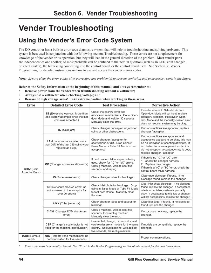
GIII Plus Operation and Service Manual44
Vender TroubleshootingUsing the Vender’s Error Code SystemThe KO controller has a built-in error code diagnostic system that will help in troubleshooting and solving problems. This system is best used in conjunction with the following section, Troubleshooting. These errors are not a replacement for knowledge of the vender or its operation, but they will lead in the general direction of the problem. Most vender parts are independent of one another, so most problems can be confined to the item in question (such as an LED, coin changer, or select switch), the harnessing connecting it to the control board, or the control board itself. See Section 3: Vender Programming for detailed instructions on how to use and access the vender’s error codes.
Note: Always clear the error codes after correcting any problem(s) to prevent confusion and unnecessary work in the future.
Refer to the Safety Information at the beginning of this manual, and always remember to:• Remove power from the vender when troubleshooting without a voltmeter;• Always use a voltmeter when checking voltage; and• Beware of high voltage areas! Take extreme caution when working in these areas.
Section 6. Vender Troubleshooting
* Error code must be manually cleared. See “Eror” in the Vender Programming section of this manual for detailed instructions.
Error Detailed Error Code Test Procedure Corrective Action
CHAr (Coin Acceptor Error)
EE (Excessive escrow: More than 255 escrow attempts since the last
coin was accepted.)
Check the escrow lever and associated mechanisms. Go to Open-door Mode and wait for 30 seconds. Manually clear the error.
If vender returns to Sales Mode from Open-door Mode without input, replace changer / acceptor. If it stays in Open-door Mode and the manually-cleared error does not reoccur, system may be okay.
nJ (Coin jam) Check changer / acceptor for jammed coins or other obstructions.
If no obstructions are apparent, replace changer / acceptor.
LA (Low acceptance rate: more than 20% of the last 255 coins were
rejected as slugs)
Check changer / acceptor for obstructions or dirt. Drop coins in Sales Mode or Tube Fill Mode to test acceptance.
If no obstructions are apparent and acceptance appears to be okay, this may be an indication of cheating attempts. If no obstructions are apparent and coins do not accept or acceptance rate is poor, replace changer / acceptor.
CC (Changer communication error)
If card reader / bill acceptor is being used, check for “rC” or “bC” errors. Unplug machine, wait at least five seconds, and replug.
If there is no “rC” or “bC” error:1. Check the changer harness.2. Replace the changer.If there is a “rC” or “bC” error, check the control board MDB harness.
tS (Tube sensor error) Check changer tubes for blockage. Clear tube blockage, if found. If no blockage found, replace the changer.
IC (Inlet chute blocked error: no coins sensed in the acceptor for
over 96 errors)
Check inlet chute for blockage. Drop coins in Sales Mode or Tube Fill Mode to test acceptance. Manually clear the error.
Clear inlet chute blockage. If no blockage found, replace the changer. If acceptance rate is acceptable, system is probably okay. If acceptance rate is low or changer will not accept coins, replace the changer.
tJXX (Tube jam error) Check changer tubes and payout for blockage.
Clear blockage, if found. If no blockage found, replace the changer.
CrCH (Changer ROM checksum error)
Unplug machine, wait at least five seconds, then replug machine. Manually clear the error.
If error does not clear, replace the changer.
CSF (Changer’s scale factor is not valid for the machine configuration)
Ensure that changer, bill acceptor, and card reader are all models for the same country. Unplug machine, wait at least five seconds, the replug machine.
If models are compatible, replace the changer.
rUnd (Remote vend)
rUC (Remote vend mechanism: no communication for five seconds) Proper communications.
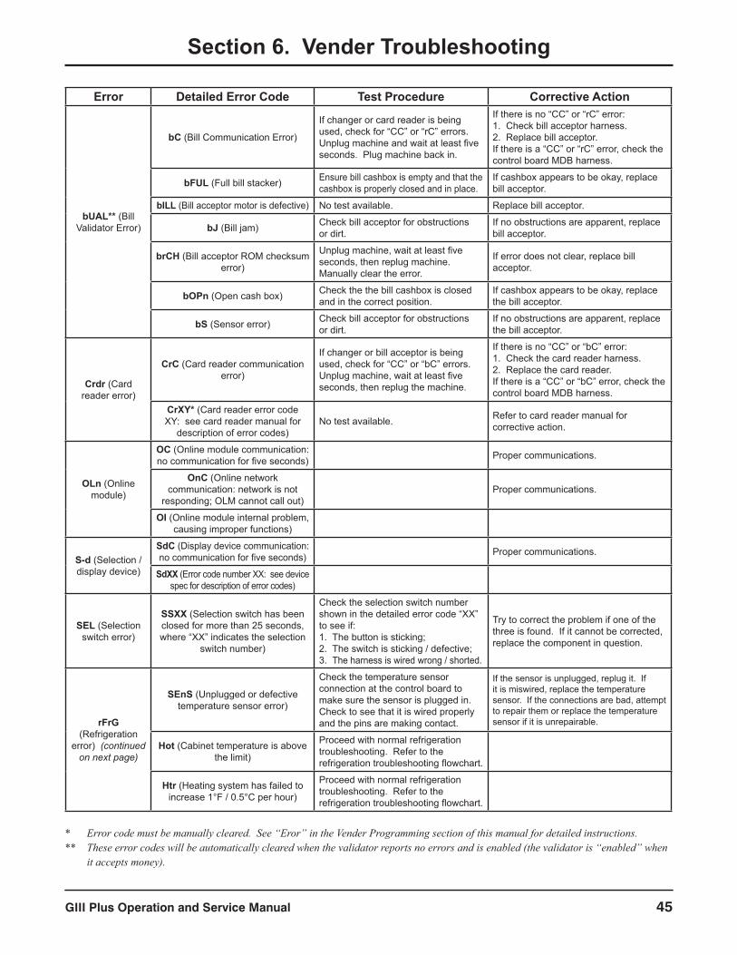
GIII Plus Operation and Service Manual 45
Section 6. Vender Troubleshooting
* Error code must be manually cleared. See “Eror” in the Vender Programming section of this manual for detailed instructions.** These error codes will be automatically cleared when the validator reports no errors and is enabled (the validator is “enabled” when
it accepts money).
Error Detailed Error Code Test Procedure Corrective Action
bUAL** (Bill Validator Error)
bC (Bill Communication Error)
If changer or card reader is being used, check for “CC” or “rC” errors. Unplug machine and wait at least five seconds. Plug machine back in.
If there is no “CC” or “rC” error:1. Check bill acceptor harness.2. Replace bill acceptor.If there is a “CC” or “rC” error, check the control board MDB harness.
bFUL (Full bill stacker) Ensure bill cashbox is empty and that the cashbox is properly closed and in place.
If cashbox appears to be okay, replace bill acceptor.
bILL (Bill acceptor motor is defective) No test available. Replace bill acceptor.
bJ (Bill jam) Check bill acceptor for obstructions or dirt.
If no obstructions are apparent, replace bill acceptor.
brCH (Bill acceptor ROM checksum error)
Unplug machine, wait at least five seconds, then replug machine. Manually clear the error.
If error does not clear, replace bill acceptor.
bOPn (Open cash box) Check the the bill cashbox is closed and in the correct position.
If cashbox appears to be okay, replace the bill acceptor.
bS (Sensor error) Check bill acceptor for obstructions or dirt.
If no obstructions are apparent, replace the bill acceptor.
Crdr (Card reader error)
CrC (Card reader communication error)
If changer or bill acceptor is being used, check for “CC” or “bC” errors. Unplug machine, wait at least five seconds, then replug the machine.
If there is no “CC” or “bC” error:1. Check the card reader harness.2. Replace the card reader.If there is a “CC” or “bC” error, check the control board MDB harness.
CrXY* (Card reader error code XY: see card reader manual for
description of error codes)No test available. Refer to card reader manual for
corrective action.
OLn (Online module)
OC (Online module communication: no communication for five seconds) Proper communications.
OnC (Online network communication: network is not
responding; OLM cannot call out)Proper communications.
OI (Online module internal problem, causing improper functions)
S-d (Selection / display device)
SdC (Display device communication: no communication for five seconds) Proper communications.
SdXX (Error code number XX: see device spec for description of error codes)
SEL (Selection switch error)
SSXX (Selection switch has been closed for more than 25 seconds, where “XX” indicates the selection
switch number)
Check the selection switch number shown in the detailed error code “XX” to see if:1. The button is sticking;2. The switch is sticking / defective;3. The harness is wired wrong / shorted.
Try to correct the problem if one of the three is found. If it cannot be corrected, replace the component in question.
rFrG (Refrigeration
error) (continued on next page)
SEnS (Unplugged or defective temperature sensor error)
Check the temperature sensor connection at the control board to make sure the sensor is plugged in. Check to see that it is wired properly and the pins are making contact.
If the sensor is unplugged, replug it. If it is miswired, replace the temperature sensor. If the connections are bad, attempt to repair them or replace the temperature sensor if it is unrepairable.
Hot (Cabinet temperature is above the limit)
Proceed with normal refrigeration troubleshooting. Refer to the refrigeration troubleshooting flowchart.
Htr (Heating system has failed to increase 1°F / 0.5°C per hour)
Proceed with normal refrigeration troubleshooting. Refer to the refrigeration troubleshooting flowchart.

GIII Plus Operation and Service Manual46
* Error code must be manually cleared. See “Eror” in the Vender Programming section of this manual for detailed instructions.
Section 6. Vender Troubleshooting
Error Detailed Error Code Test Procedure Corrective Action
rFrG (Refrigeration
error) (continued from previous
page)
CoLd (Temperature 3°F / 1.5°C or more below the compressor cut-out
setting)
1. Check the refrigeration unit before opening the vender’s main door to see if it is running.2. Open the vender’s main door and see if the unit cuts off.3. Make sure the vender’s door switch is working properly.4. Unplug one of the two white wires plugged into the refrigeration relay.
If upon unplugging one of the white wires, the unit stops:1. Check the temperature sensor reading.2. Check SetP settings.3. Check the two white wires for shorts from the control board.If upon unplugging one of the two white wires, the unit still runs:1. Unplug one of the black wires. If the unit stops, replace the refrigeration relay. If optional heater kit is not installed, one may be required.2. If heater kit is installed and heater does not turn on (heater relay does not click upon energizing with the relay test mode), check the two white wires from the board to the heater relay for voltage. (There should be 24 VDC on one of the two wires.) Check the other wire for continuity between the control board and the relay. If voltage is okay, replace the relay. Otherwise, replace the control board.
CnPr (Compressor is not cooling within 30 minutes of turning on)
Check the refrigeration unit before opening the vender’s main door to see if it is running.
If the unit is running, clear the error to see if it reoccurs.
Open the vender’s main door and check the display to see that the door switch is working as normal.
If the display does not function as normal, check the door switch circuit.
Access the “rFrG” mode and check the “SetP” settings. While in “rFrG,” change “dSP” to “1” to show the temperature on the display during the greeting and see if it is correct.
Change any settings, if necessary, and check the temperature sensor operation.
While in the “tESt” mode, access the “rELy” mode and turn the compressor on.
If the unit does not run (refrigeration relay not clicking upon energizing with the relay test mode), check the two white wires from the board to the refrigeration relay for voltage. There should be 24 VDC on one of the two wires). Check the other wire for continuity between the control board and relay. Note: The compressor relay test mode must be on to check voltage.
StS (Space-to-sales error)
UAXX (Unassigned column, where “XX” indicates the column number)
Access the Space-to-sales Mode (“StoS”) and go to Custom Space-to-sales (“CStS”). Check all selections for the column shown in the detailed error code “XX.”
Change the space-to-sales settings as required. In some situations, it may be quicker to completely reset all space-to-sales settings.
Chut (Chute sensor error)
CS* (Chute sensor error: chute sensor is active for more than five
minutes)
Check to make sure the sensor is properly adjusted. Make sure the adjustment only blinks on when product impacts the delivery chute.
Adjust the sensor to factory spec. See “Taking Care of the Vender” in Section 5 for detailed instructions.
COLJ (Column jam error)
CJXX* (Column jam error, where “XX” indicates the column number)
Check column for problem. Correct problem.
Check for contamination on release lever, pivot, and pivot end. Clean contamination.
Enter “tESt” and vend one time from column.
If two or more products are received, increase chute sensor sensitivity or replace chute sensor. To increase sensitivity, turn screw clockwise. See “Chut” section.

GIII Plus Operation and Service Manual 47
* Error code must be manually cleared. See “Eror” in the Vender Programming section of this manual for detailed instructions.
Section 6. Vender Troubleshooting
Error Detailed Error Code Test Procedure Corrective Action
UEnd (Vend mechanism error)
hS* (Home sensor error)
Observe the chain to make sure the four actuators (“rabbits”) are attached. Make sure two of the four actuators have magnets pressed in them.
If defective, replace the chain assembly.
Make sure that the magnets are facing the rear of the cabinet.
If the magnets face forward, the chain is installed backward. Remove the chain and reinstall it so that the magnets face the rear of the cabinet.
Check the location of the chain. The actuators should be at each end of the cabinet. Pull the chain until both sets of actuators are in the middle of the cabinet. Power the vender down, then restore power. The bottom set of actuators should end up in the home position.
If the motor jerks but does not rotate the chain, check the motor’s wiring to the control board. If nothing is found, replace the vend motor assembly. If the chain rotates several times without an actuator stopping above the vend motor (at the home sensor), check the above test. It is is okay, then check the home sensor wiring to see if it’s pinched or shorted. Replace the home sensor if nothing is found.
EC* (Encoder error)Learn how column sequencing works and vend from all columns, watching the actuators locate each column.
If the encoder is defective, the vend motor will not be able to find the release levers for one or more of the columns and will stop at a place where there is no release lever. Replace the vend motor assembly. This error may also indicate that the chain is sticky, making it difficult for the chain to move. See “Taking Care of the Vender” on how to clean the chain.
rE* (Rabbit error)
Closely examine the four rabbits (actuators) mounted on the chain assembly. Make sure they are tightly mounted and none are missing.
If an actuator is missing, replace the chain assembly.
Check to make sure that the upper run of the chain assembly is above the stabilizers.
If the upper run of the chain assembly is below the stabilizers, raise it above them.
Check the chain’s alignment under the mechanism. Check the idler pulley sprocket and the vend motor sprocket to see if aligned.
If the idler pulley sprocket is in the wrong position on the shaft, order a new idler sprocket assembly. If the vend motor sprocket is in the wrong position on the shaft, order a new vend motor assembly.
Ctrl (Control system error)
dS* (Door switch error)
Check the vender’s door to see if it’s sticking or miswired. If nothing is found at the door switch, check two wires from door switch to control board to see if they’re pinched or shorted.
Replace the door switch, if defective. Repair or replace the door switch harness to the control board.
ACLo* (Average rectified voltage was under 22 VDC for at least 30
consecutive seconds)
Check for low voltage at the wall outlet, at refrigeration unit startup with all else on circuit running, in an “extreme” condition.
If low voltage cannot be found on the wall outlet in an extreme condition, check for shorts in the vender.
rAM (Setup info corrupted) No test available. If error shows up frequently, replace the control board.
SF (Scale factor error)Check the connections of the changer harness. Make sure the changer is plugged in and is working.
Make corrections to the harness or replace the changer if necessary.
IS (Inlet sensor blocked) Check the changer harnessing for cut, pinched, or crimped wires. Replace the changer.
Ib (Inlet blocked)
Check the inlet for blockage. If nothing is found, check the changer harnessing for cut, pinched, or crimped wires. Replace the changer if necessary.
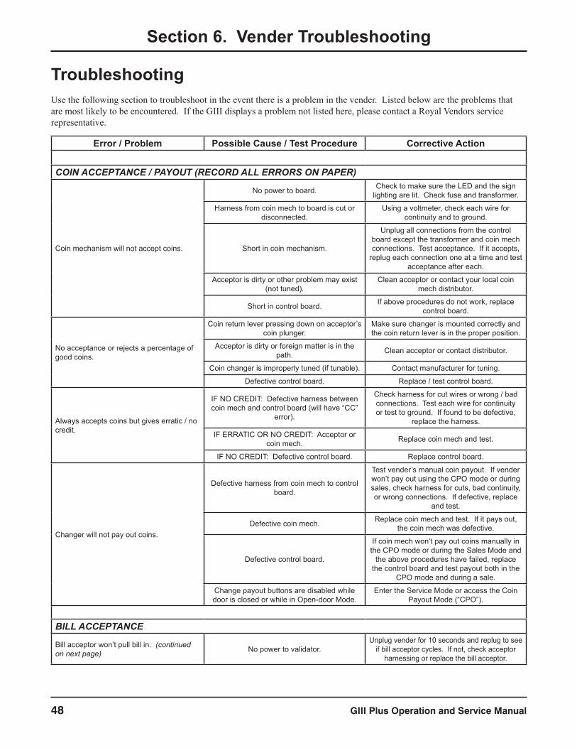
GIII Plus Operation and Service Manual48
Section 6. Vender Troubleshooting
TroubleshootingUse the following section to troubleshoot in the event there is a problem in the vender. Listed below are the problems that are most likely to be encountered. If the GIII displays a problem not listed here, please contact a Royal Vendors service representative.
Error / Problem Possible Cause / Test Procedure Corrective Action
COIN ACCEPTANCE / PAYOUT (RECORD ALL ERRORS ON PAPER)
Coin mechanism will not accept coins.
No power to board. Check to make sure the LED and the sign lighting are lit. Check fuse and transformer.
Harness from coin mech to board is cut or disconnected.
Using a voltmeter, check each wire for continuity and to ground.
Short in coin mechanism.
Unplug all connections from the control board except the transformer and coin mech connections. Test acceptance. If it accepts,
replug each connection one at a time and test acceptance after each.
Acceptor is dirty or other problem may exist (not tuned).
Clean acceptor or contact your local coin mech distributor.
Short in control board. If above procedures do not work, replace control board.
No acceptance or rejects a percentage of good coins.
Coin return lever pressing down on acceptor’s coin plunger.
Make sure changer is mounted correctly and the coin return lever is in the proper position.
Acceptor is dirty or foreign matter is in the path. Clean acceptor or contact distributor.
Coin changer is improperly tuned (if tunable). Contact manufacturer for tuning.
Defective control board. Replace / test control board.
Always accepts coins but gives erratic / no credit.
IF NO CREDIT: Defective harness between coin mech and control board (will have “CC”
error).
Check harness for cut wires or wrong / bad connections. Test each wire for continuity or test to ground. If found to be defective,
replace the harness.
IF ERRATIC OR NO CREDIT: Acceptor or coin mech. Replace coin mech and test.
IF NO CREDIT: Defective control board. Replace control board.
Changer will not pay out coins.
Defective harness from coin mech to control board.
Test vender’s manual coin payout. If vender won’t pay out using the CPO mode or during sales, check harness for cuts, bad continuity, or wrong connections. If defective, replace
and test.
Defective coin mech. Replace coin mech and test. If it pays out, the coin mech was defective.
Defective control board.
If coin mech won’t pay out coins manually in the CPO mode or during the Sales Mode and
the above procedures have failed, replace the control board and test payout both in the
CPO mode and during a sale.
Change payout buttons are disabled while door is closed or while in Open-door Mode.
Enter the Service Mode or access the Coin Payout Mode (“CPO”).
BILL ACCEPTANCE
Bill acceptor won’t pull bill in. (continued on next page) No power to validator.
Unplug vender for 10 seconds and replug to see if bill acceptor cycles. If not, check acceptor
harnessing or replace the bill acceptor.
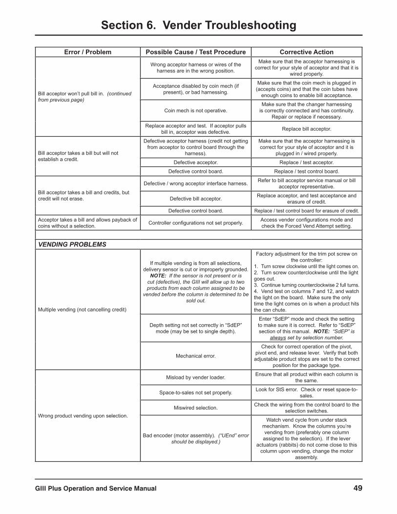
GIII Plus Operation and Service Manual 49
Section 6. Vender Troubleshooting
Error / Problem Possible Cause / Test Procedure Corrective Action
Bill acceptor won’t pull bill in. (continued from previous page)
Wrong acceptor harness or wires of the harness are in the wrong position.
Make sure that the acceptor harnessing is correct for your style of acceptor and that it is
wired properly.
Acceptance disabled by coin mech (if present), or bad harnessing.
Make sure that the coin mech is plugged in (accepts coins) and that the coin tubes have
enough coins to enable bill acceptance.
Coin mech is not operative.Make sure that the changer harnessing
is correctly connected and has continuity. Repair or replace if necessary.
Replace acceptor and test. If acceptor pulls bill in, acceptor was defective. Replace bill acceptor.
Bill acceptor takes a bill but will not establish a credit.
Defective acceptor harness (credit not getting from acceptor to control board through the
harness).
Make sure that the acceptor harnessing is correct for your style of acceptor and it is
plugged in / wired properly.
Defective acceptor. Replace / test acceptor.
Defective control board. Replace / test control board.
Bill acceptor takes a bill and credits, but credit will not erase.
Defective / wrong acceptor interface harness. Refer to bill acceptor service manual or bill acceptor representative.
Defective bill acceptor. Replace acceptor, and test acceptance and erasure of credit.
Defective control board. Replace / test control board for erasure of credit.
Acceptor takes a bill and allows payback of coins without a selection. Controller configurations not set properly. Access vender configurations mode and
check the Forced Vend Attempt setting.
VENDING PROBLEMS
Multiple vending (not cancelling credit)
If multiple vending is from all selections, delivery sensor is cut or improperly grounded.
NOTE: If the sensor is not present or is cut (defective), the GIII will allow up to two products from each column assigned to be
vended before the column is determined to be sold out.
Factory adjustment for the trim pot screw on the controller:
1. Turn screw clockwise until the light comes on.2. Turn screw counterclockwise until the light goes out.3. Continue turning counterclockwise 2 full turns.4. Vend test on columns 7 and 12, and watch the light on the board. Make sure the only time the light comes on is when a product hits the can chute.
Depth setting not set correctly in “SdEP” mode (may be set to single depth).
Enter “SdEP” mode and check the setting to make sure it is correct. Refer to “SdEP” section of this manual. NOTE: “SdEP” is
always set by selection number.
Mechanical error.
Check for correct operation of the pivot, pivot end, and release lever. Verify that both adjustable product stops are set to the correct
position for the package type.
Wrong product vending upon selection.
Misload by vender loader. Ensure that all product within each column is the same.
Space-to-sales not set properly. Look for StS error. Check or reset space-to-sales.
Miswired selection. Check the wiring from the control board to the selection switches.
Bad encoder (motor assembly). (“UEnd” error should be displayed.)
Watch vend cycle from under stack mechanism. Know the columns you’re vending from (preferably one column
assigned to the selection). If the lever actuators (rabbits) do not come close to this
column upon vending, change the motor assembly.
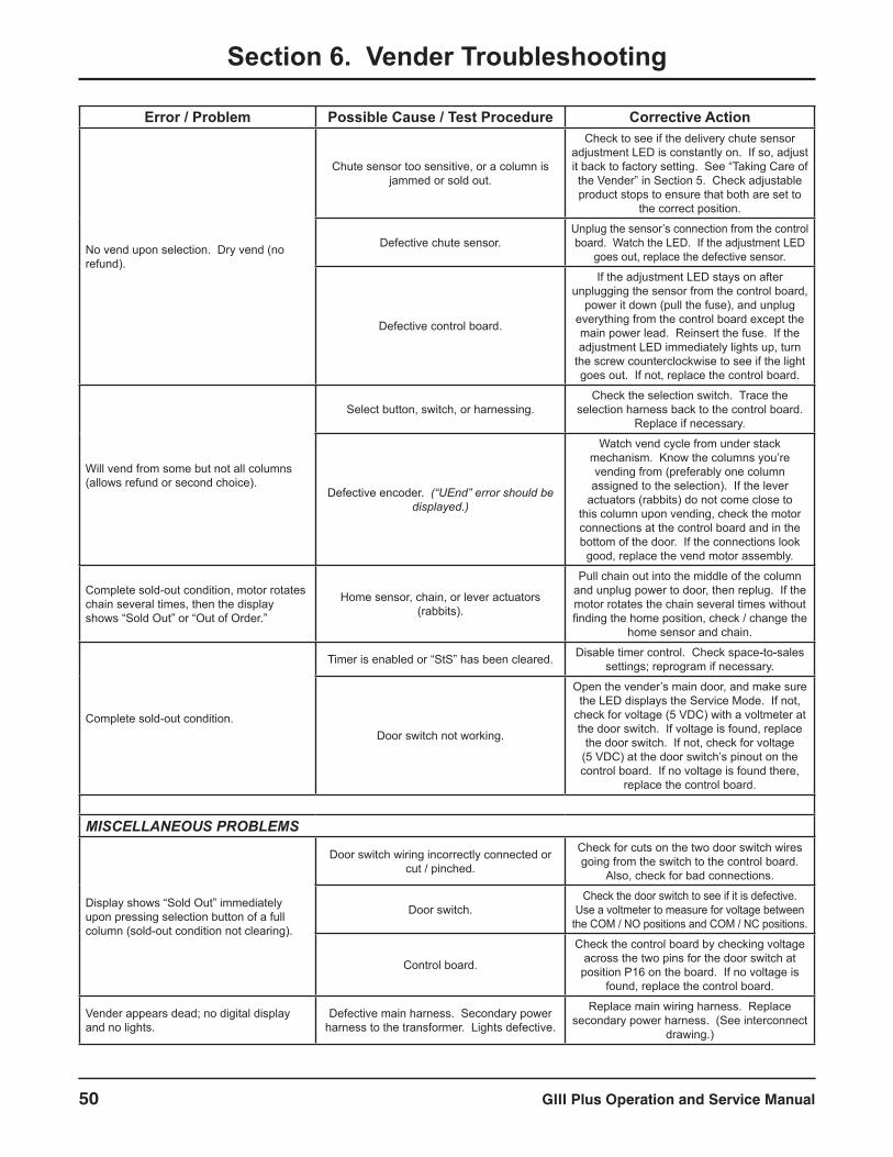
GIII Plus Operation and Service Manual50
Section 6. Vender Troubleshooting
Error / Problem Possible Cause / Test Procedure Corrective Action
No vend upon selection. Dry vend (no refund).
Chute sensor too sensitive, or a column is jammed or sold out.
Check to see if the delivery chute sensor adjustment LED is constantly on. If so, adjust it back to factory setting. See “Taking Care of the Vender” in Section 5. Check adjustable product stops to ensure that both are set to
the correct position.
Defective chute sensor.Unplug the sensor’s connection from the control board. Watch the LED. If the adjustment LED
goes out, replace the defective sensor.
Defective control board.
If the adjustment LED stays on after unplugging the sensor from the control board,
power it down (pull the fuse), and unplug everything from the control board except the main power lead. Reinsert the fuse. If the adjustment LED immediately lights up, turn
the screw counterclockwise to see if the light goes out. If not, replace the control board.
Will vend from some but not all columns (allows refund or second choice).
Select button, switch, or harnessing.Check the selection switch. Trace the
selection harness back to the control board. Replace if necessary.
Defective encoder. (“UEnd” error should be displayed.)
Watch vend cycle from under stack mechanism. Know the columns you’re vending from (preferably one column
assigned to the selection). If the lever actuators (rabbits) do not come close to
this column upon vending, check the motor connections at the control board and in the bottom of the door. If the connections look
good, replace the vend motor assembly.
Complete sold-out condition, motor rotates chain several times, then the display shows “Sold Out” or “Out of Order.”
Home sensor, chain, or lever actuators (rabbits).
Pull chain out into the middle of the column and unplug power to door, then replug. If the motor rotates the chain several times without finding the home position, check / change the
home sensor and chain.
Complete sold-out condition.
Timer is enabled or “StS” has been cleared. Disable timer control. Check space-to-sales settings; reprogram if necessary.
Door switch not working.
Open the vender’s main door, and make sure the LED displays the Service Mode. If not,
check for voltage (5 VDC) with a voltmeter at the door switch. If voltage is found, replace
the door switch. If not, check for voltage (5 VDC) at the door switch’s pinout on the control board. If no voltage is found there,
replace the control board.
MISCELLANEOUS PROBLEMS
Display shows “Sold Out” immediately upon pressing selection button of a full column (sold-out condition not clearing).
Door switch wiring incorrectly connected or cut / pinched.
Check for cuts on the two door switch wires going from the switch to the control board.
Also, check for bad connections.
Door switch.Check the door switch to see if it is defective.
Use a voltmeter to measure for voltage between the COM / NO positions and COM / NC positions.
Control board.
Check the control board by checking voltage across the two pins for the door switch at
position P16 on the board. If no voltage is found, replace the control board.
Vender appears dead; no digital display and no lights.
Defective main harness. Secondary power harness to the transformer. Lights defective.
Replace main wiring harness. Replace secondary power harness. (See interconnect
drawing.)
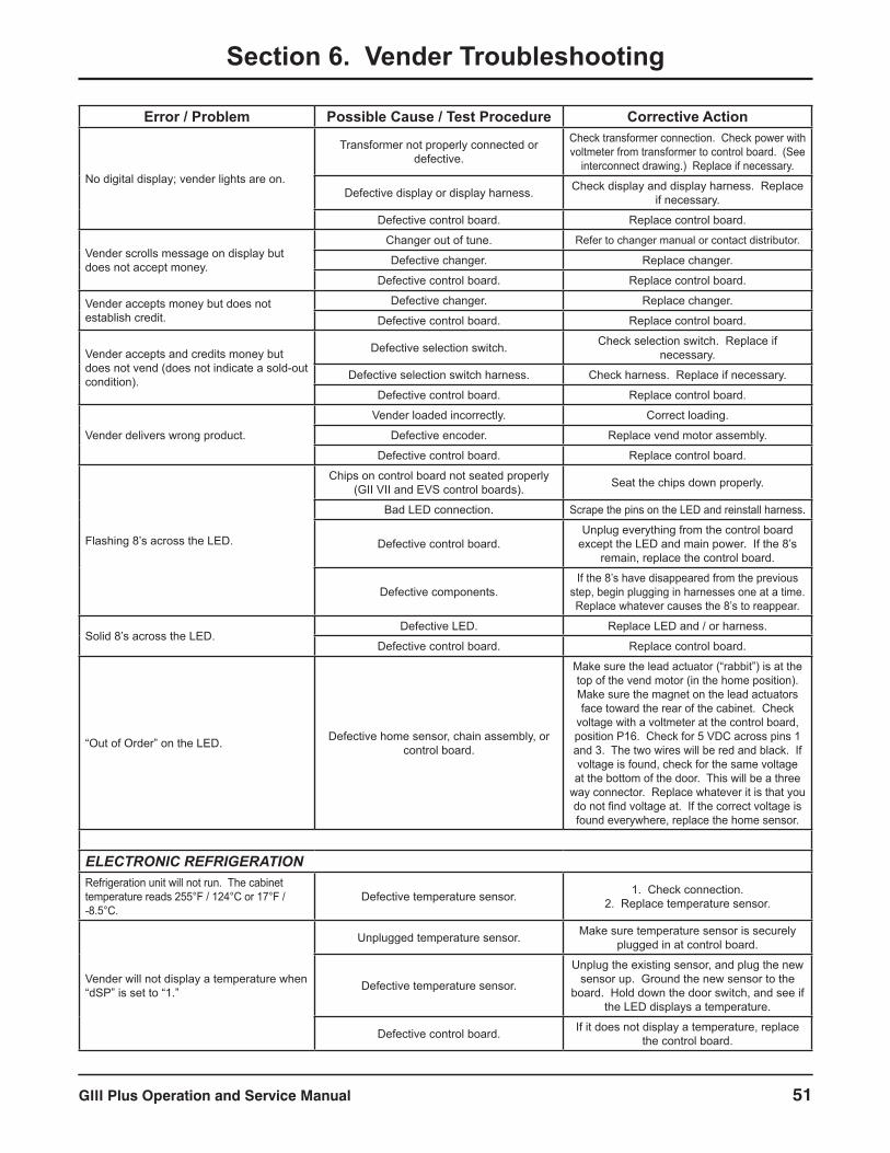
GIII Plus Operation and Service Manual 51
Section 6. Vender Troubleshooting
Error / Problem Possible Cause / Test Procedure Corrective Action
No digital display; vender lights are on.
Transformer not properly connected or defective.
Check transformer connection. Check power with voltmeter from transformer to control board. (See
interconnect drawing.) Replace if necessary.
Defective display or display harness. Check display and display harness. Replace if necessary.
Defective control board. Replace control board.
Vender scrolls message on display but does not accept money.
Changer out of tune. Refer to changer manual or contact distributor.
Defective changer. Replace changer.
Defective control board. Replace control board.
Vender accepts money but does not establish credit.
Defective changer. Replace changer.
Defective control board. Replace control board.
Vender accepts and credits money but does not vend (does not indicate a sold-out condition).
Defective selection switch. Check selection switch. Replace if necessary.
Defective selection switch harness. Check harness. Replace if necessary.
Defective control board. Replace control board.
Vender delivers wrong product.
Vender loaded incorrectly. Correct loading.
Defective encoder. Replace vend motor assembly.
Defective control board. Replace control board.
Flashing 8’s across the LED.
Chips on control board not seated properly (GII VII and EVS control boards). Seat the chips down properly.
Bad LED connection. Scrape the pins on the LED and reinstall harness.
Defective control board.Unplug everything from the control board
except the LED and main power. If the 8’s remain, replace the control board.
Defective components.If the 8’s have disappeared from the previous
step, begin plugging in harnesses one at a time. Replace whatever causes the 8’s to reappear.
Solid 8’s across the LED.Defective LED. Replace LED and / or harness.
Defective control board. Replace control board.
“Out of Order” on the LED. Defective home sensor, chain assembly, or control board.
Make sure the lead actuator (“rabbit”) is at the top of the vend motor (in the home position). Make sure the magnet on the lead actuators face toward the rear of the cabinet. Check
voltage with a voltmeter at the control board, position P16. Check for 5 VDC across pins 1 and 3. The two wires will be red and black. If voltage is found, check for the same voltage at the bottom of the door. This will be a three
way connector. Replace whatever it is that you do not find voltage at. If the correct voltage is found everywhere, replace the home sensor.
ELECTRONIC REFRIGERATIONRefrigeration unit will not run. The cabinet temperature reads 255°F / 124°C or 17°F / -8.5°C.
Defective temperature sensor. 1. Check connection.2. Replace temperature sensor.
Vender will not display a temperature when “dSP” is set to “1.”
Unplugged temperature sensor. Make sure temperature sensor is securely plugged in at control board.
Defective temperature sensor.
Unplug the existing sensor, and plug the new sensor up. Ground the new sensor to the
board. Hold down the door switch, and see if the LED displays a temperature.
Defective control board. If it does not display a temperature, replace the control board.
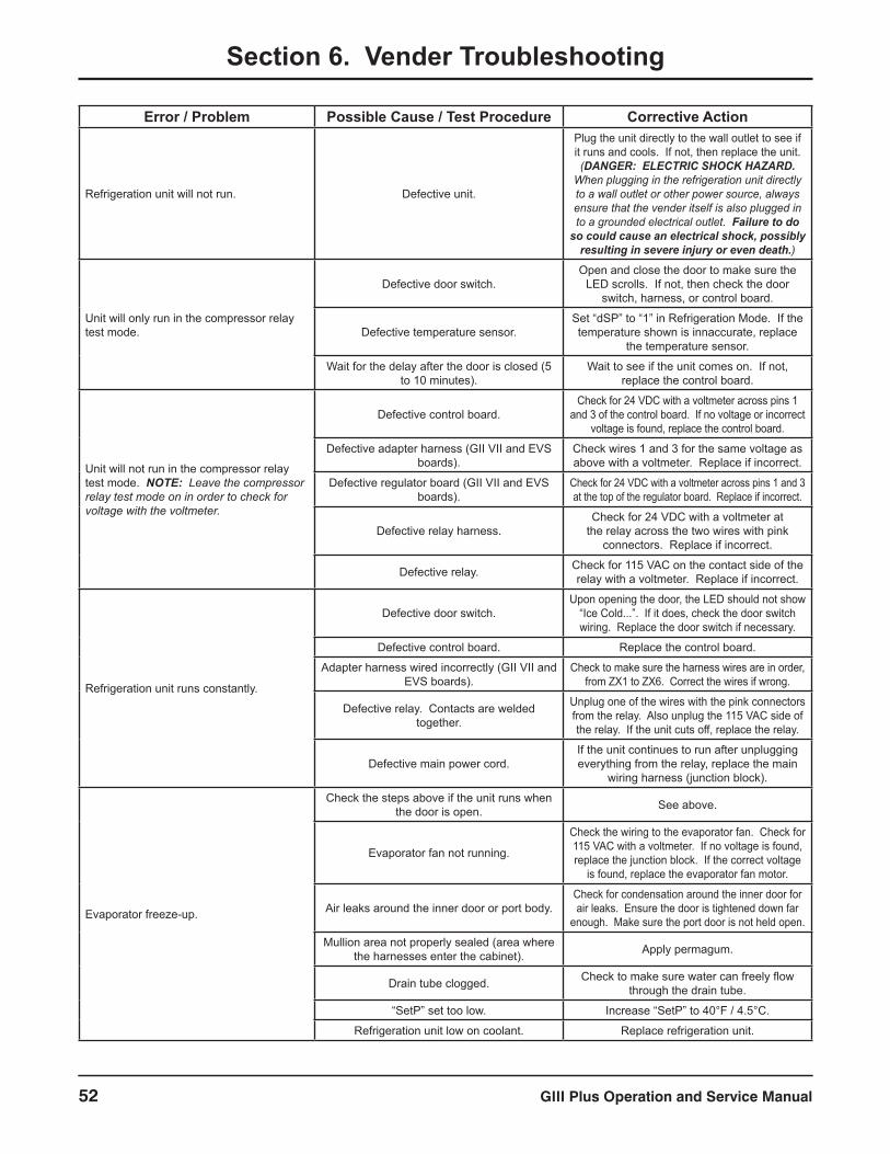
GIII Plus Operation and Service Manual52
Section 6. Vender Troubleshooting
Error / Problem Possible Cause / Test Procedure Corrective Action
Refrigeration unit will not run. Defective unit.
Plug the unit directly to the wall outlet to see if it runs and cools. If not, then replace the unit. (DANGER: ELECTRIC SHOCK HAZARD.
When plugging in the refrigeration unit directly to a wall outlet or other power source, always ensure that the vender itself is also plugged in to a grounded electrical outlet. Failure to do
so could cause an electrical shock, possibly resulting in severe injury or even death.)
Unit will only run in the compressor relay test mode.
Defective door switch.Open and close the door to make sure the
LED scrolls. If not, then check the door switch, harness, or control board.
Defective temperature sensor.Set “dSP” to “1” in Refrigeration Mode. If the temperature shown is innaccurate, replace
the temperature sensor.
Wait for the delay after the door is closed (5 to 10 minutes).
Wait to see if the unit comes on. If not, replace the control board.
Unit will not run in the compressor relay test mode. NOTE: Leave the compressor relay test mode on in order to check for voltage with the voltmeter.
Defective control board.Check for 24 VDC with a voltmeter across pins 1
and 3 of the control board. If no voltage or incorrect voltage is found, replace the control board.
Defective adapter harness (GII VII and EVS boards).
Check wires 1 and 3 for the same voltage as above with a voltmeter. Replace if incorrect.
Defective regulator board (GII VII and EVS boards).
Check for 24 VDC with a voltmeter across pins 1 and 3 at the top of the regulator board. Replace if incorrect.
Defective relay harness.Check for 24 VDC with a voltmeter at
the relay across the two wires with pink connectors. Replace if incorrect.
Defective relay. Check for 115 VAC on the contact side of the relay with a voltmeter. Replace if incorrect.
Refrigeration unit runs constantly.
Defective door switch.Upon opening the door, the LED should not show
“Ice Cold...”. If it does, check the door switch wiring. Replace the door switch if necessary.
Defective control board. Replace the control board.
Adapter harness wired incorrectly (GII VII and EVS boards).
Check to make sure the harness wires are in order, from ZX1 to ZX6. Correct the wires if wrong.
Defective relay. Contacts are welded together.
Unplug one of the wires with the pink connectors from the relay. Also unplug the 115 VAC side of the relay. If the unit cuts off, replace the relay.
Defective main power cord.If the unit continues to run after unplugging everything from the relay, replace the main
wiring harness (junction block).
Evaporator freeze-up.
Check the steps above if the unit runs when the door is open. See above.
Evaporator fan not running.
Check the wiring to the evaporator fan. Check for 115 VAC with a voltmeter. If no voltage is found, replace the junction block. If the correct voltage
is found, replace the evaporator fan motor.
Air leaks around the inner door or port body.Check for condensation around the inner door for air leaks. Ensure the door is tightened down far
enough. Make sure the port door is not held open.
Mullion area not properly sealed (area where the harnesses enter the cabinet). Apply permagum.
Drain tube clogged. Check to make sure water can freely flow through the drain tube.
“SetP” set too low. Increase “SetP” to 40°F / 4.5°C.
Refrigeration unit low on coolant. Replace refrigeration unit.
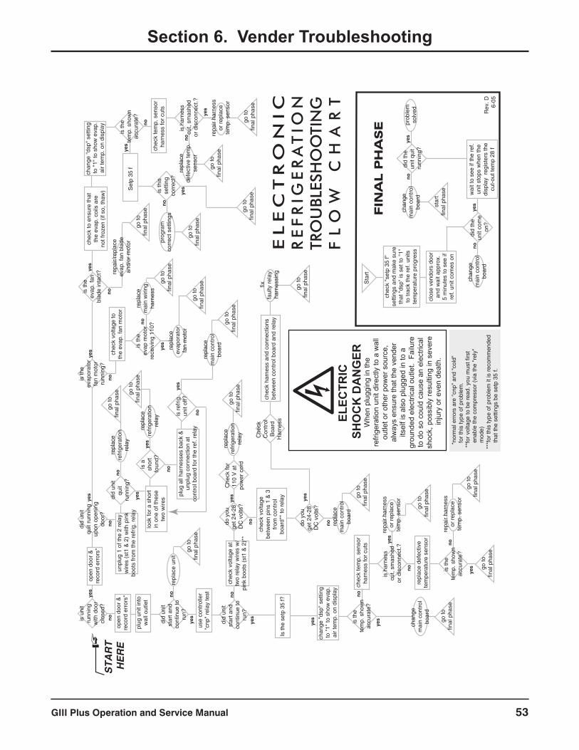
GIII Plus Operation and Service Manual 53
Section 6. Vender Troubleshooting
yes
yes
yes
yes
no
yesno
nono
no
no
no
yes
no
yes
yes
no
yes
no
yes
yes
no
yes
no
yes
yes
yes
no
no
yes
no
no
yes
no
yes
no
yes
clos
e ve
ndor
s do
oran
d w
ait a
ppro
x.5
min
utes
to s
ee if
ref.
unit
com
es o
n
wai
t to
see
if th
e re
f.un
it st
ops
whe
n th
edi
spla
y re
gist
ers
the
cut-o
ut te
mp
28 f
star
tfin
al p
hase
FIN
AL P
HA
SE
noye
s
yes
did
the
unit
com
e on
?
did
the
unit
quit
runn
ing?
chan
ge
mai
n co
ntro
lbo
ard
noch
ange
m
ain
cont
rol
boar
d
prob
lem
solv
ed
chec
k "s
etp
35 f"
setti
ngs
and
mak
e su
reth
at "
dsp"
is s
et to
"1"
to tr
ack
the
ref.
units
tem
pera
ture
pro
gres
sEL
EC
TR
ON
IC
R
EF
RIG
ER
AT
ION
TR
OU
BLES
HO
OTI
NG
F
LO
W
CH
AR
T
open
doo
r &re
cord
err
ors*
chec
k vo
ltage
toth
e ev
ap. f
an m
otor
chec
k to
ens
ure
that
the
evap
. coi
ls a
reno
t fro
zen
(if s
o, th
aw)
plug
uni
t int
ow
all o
utle
t
use
cont
rolle
r"c
np"
rela
y te
st
plug
all
harn
esse
s ba
ck &
unpl
ug c
onne
ctio
n at
cont
rol b
oard
for t
he re
f. re
lay
repl
ace
unit
did
unit
star
t and
co
ntin
ue to
run?
do y
ouge
t 24-
28
DC
vol
ts?
Is th
e se
tp 3
5 f?
chec
k vo
ltage
betw
een
pins
1 &
3fro
m c
ontro
lbo
ard*
* to
rela
y
chec
k ha
rnes
s an
d co
nnec
tions
be
twee
n co
ntro
l boa
rd a
nd re
lay
do y
ouge
t 24-
28
DC
vol
ts?
chec
k vo
ltage
at
two
rela
y w
ires
w/
pink
boo
ts (s
t1 &
2)*
*
repa
ir ha
rnes
sor
repl
ace
tem
p. s
enso
r
repa
ir ha
rnes
sor
repl
ace
tem
p. s
enso
r
chan
ge "
dsp"
set
ting
to "
1" to
sho
w e
vap.
air t
emp.
on
disp
lay
is th
e te
mp.
sho
wn
accu
rate
?
repl
ace
mai
n co
ntro
lbo
ard
is th
e te
mp.
sho
wn
accu
rate
?
is h
arne
ss
cut,
smas
hed
or d
isco
nnec
t.?
chec
k te
mp.
sen
sor
harn
ess
for c
uts
repl
ace
defe
ctiv
ete
mpe
ratu
re s
enso
rgo
tofin
al p
hase
go to
final
pha
se
go to
final
pha
se
go to
final
pha
se
go to
final
pha
se
go to
final
pha
se
go to
final
pha
se
go to
final
pha
se
fixfa
ulty
rela
y ha
rnes
sing
is th
eev
apor
ator
fan
mot
orru
nnin
g?
is th
eev
ap m
otor
rece
ivin
g 11
0?
repl
ace
refri
gera
tion
rela
y
go to
final
pha
se
go to
final
pha
se
go to
final
pha
se
repl
ace
refri
gera
tion
rela
y
go to
final
pha
se
repl
ace
evap
orat
orfa
n m
otor
go to
final
pha
se
go to
final
pha
sere
plac
em
ain
wiri
ngha
rnes
s
repa
ir/re
plac
eev
ap. f
an b
lade
and/
or m
otor
is u
nit
runn
ing
with
doo
rcl
osed
?
did
unit
star
t and
co
ntin
ue to
run?
open
doo
r &re
cord
err
ors*
did
unit
quit
runn
ing
upon
ope
ning
door
?
did
unit
quit
runn
ing?
is re
frig.
unit
off?
is a
sh
ort
foun
d?
unpl
ug 1
of t
he 2
rela
yw
ires
(st1
& 2
) with
pin
kbo
ots
from
the
refri
g. re
lay
repl
ace
refri
gera
tion
rela
y
repl
ace
mai
n co
ntro
lbo
ard
look
for a
sho
rtin
one
of t
hese
two
wire
s
is th
eev
ap. f
anbl
ade
inta
ct?
repl
ace
defe
ctiv
e te
mp.
sens
or
prog
ram
corr
ect s
ettin
gs
chan
ge "
dsp"
set
ting
to "
1" to
sho
w e
vap.
air t
emp.
on
disp
lay
is th
e te
mp.
sho
wn
accu
rate
?
is h
arne
ss
cut,
smas
hed
or d
isco
nnec
t.?
chec
k te
mp.
sen
sor
harn
ess
for c
uts
Set
p 35
f
go to
final
pha
se
go to
final
pha
se
go to
final
pha
se
go to
final
pha
se
repa
ir ha
rnes
sor
repl
ace
tem
p. s
enso
r
is th
isse
tting
corr
ect?
chan
ge
mai
n co
ntro
lbo
ard
*nor
mal
err
ors
are
"cnp
" an
d "c
old"
for t
his
type
of p
robl
em.
**fo
r vol
tage
to b
e re
ad. y
ou m
ust f
irst
en
able
the
com
pres
sor (
via
the
"rel
y"
mod
e)
***f
or th
is ty
pe o
f pro
blem
it is
reco
mm
ende
d
that
the
setti
ngs
be s
etp
35 f.
STA
RT
HE
RE
Rev
. D6-
05
Sta
rt
Che
ck
Con
trol
Boa
rdH
arne
ss
Che
ck fo
r11
0 V
at
pow
er c
ord
ELEC
TRIC
SH
OC
K D
AN
GER
Whe
n pl
uggi
ng in
the
refri
gera
tion
unit
dire
ctly
to a
wal
l ou
tlet o
r oth
er p
ower
sou
rce,
al
way
s en
sure
that
the
vend
er
itsel
f is
also
plu
gged
in to
a
grou
nded
ele
ctric
al o
utle
t. F
ailu
re
to d
o so
cou
ld c
ause
an
elec
trica
l sh
ock,
pos
sibl
y re
sulti
ng in
sev
ere
inju
ry o
r eve
n de
ath.

GIII Plus Operation and Service Manual54
Section 7. Training Guide
Training GuideTroubleshooting TechniqueObjectiveUnderstand sequence of operation, identify what vender is doing, and compare to what it should be doing.
• Find defective component, confirm failed component, repair / replace component, test to confirm fix;
• Identify source, path, or load;• Distinguish between software and hardware; and• Repair the problem, not the symptom.
Simple circuit• Power supply (source – example: control board)• Line (path – example: display harness)• Device (load – example: LED / LCD)• Failure of any one results in service call.• Skill required is systematical, logical process of
elimination.1. Do I have power?2. Can the power get to where I want it?3. Does the device work?
• Confirm through use of volt / ohm meter.• Understand the impact of software on hardware.• Test to confirm repair.• Low-voltage circuits are affected by harness
connections, insulation, line noise, polarity, and ground.• The meter is not an option when checking low-voltage
circuits.
Component HighlightsControl board• “Brains” of vender• Controls all vending operations• See Section 2. Vender Component Explanation for full
explanations of control board pinouts and functions.
Power supply (see Figure 7.1)• Supplies 24 VAC (±10%) to the control board• Only AC voltage at control board• Check for primary voltage to transformer at light
harness• Check for secondary voltage across position P5, pins 2
and 4• Secondary is protected by a 3-amp fuse• Ohm out fuse holder
P5 4
4
3
3
2
2
1
1
3
3
2
2
1
1
BLACK
(24 VAC)
RED
(24 VAC)
BLACK
(24 VAC)
RED
(24 VAC)
TRANSFORMER
24 VAC
3A FUSE
Figure 7.1: Power supply.
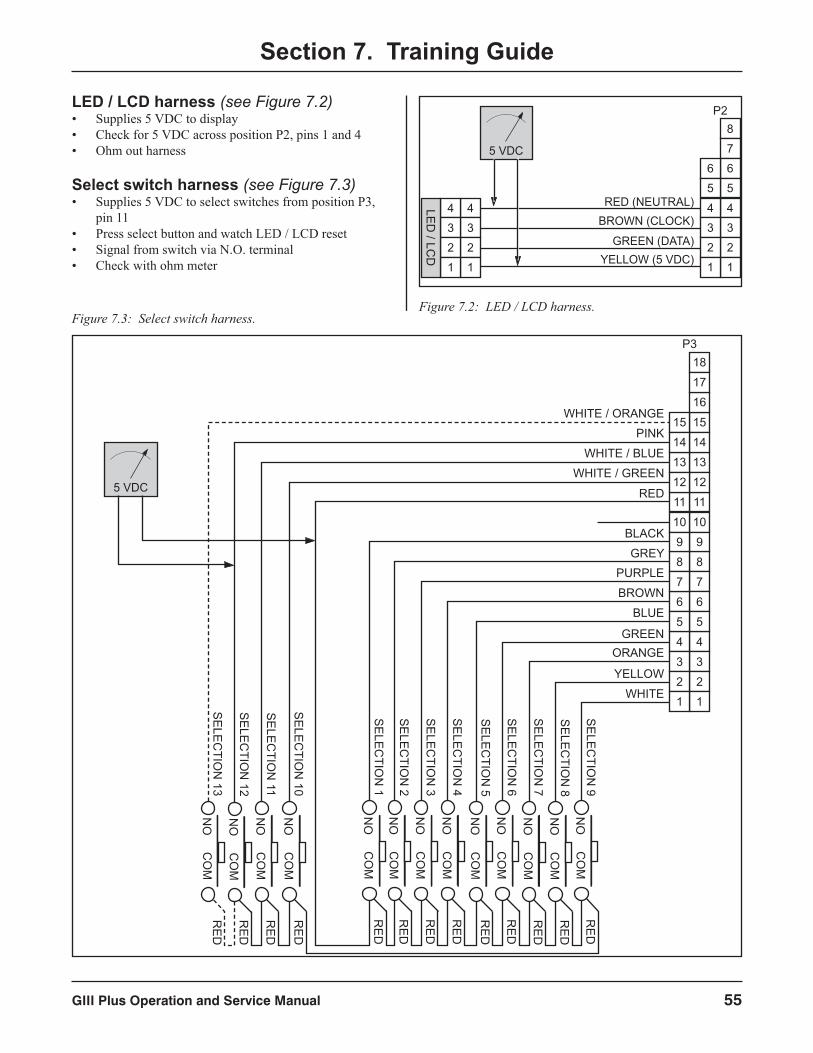
GIII Plus Operation and Service Manual 55
Section 7. Training Guide
LED / LCD harness (see Figure 7.2)• Supplies 5 VDC to display• Check for 5 VDC across position P2, pins 1 and 4• Ohm out harness
Select switch harness (see Figure 7.3)• Supplies 5 VDC to select switches from position P3,
pin 11• Press select button and watch LED / LCD reset• Signal from switch via N.O. terminal• Check with ohm meter
Figure 7.2: LED / LCD harness.
5 VDC
RED (NEUTRAL)BROWN (CLOCK)
GREEN (DATA)YELLOW (5 VDC)
4
3
2
1
4
3
2
1
LED
/ LCD
4
3
2
1
4
3
2
1
8
7
6
5
6
5
P2
4
3
2
1
4
3
2
1
8
7
6
5
6
5
P3
8
7
10
9
10
9
11
13
12
15
14
11
13
12
15
14
16
18
17
SE
LEC
TION
9N
OC
OM
RE
D
SE
LEC
TION
8N
OC
OM
RE
D
SE
LEC
TION
7N
OC
OM
RE
D
SE
LEC
TION
6N
OC
OM
RE
D
SE
LEC
TION
5N
OC
OM
RE
D
SE
LEC
TION
4N
OC
OM
RE
D
SE
LEC
TION
3N
OC
OM
RE
D
SE
LEC
TION
2N
OC
OM
RE
D
SE
LEC
TION
1N
OC
OM
RE
D
SE
LEC
TION
10N
OC
OM
RE
D
SE
LEC
TION
11N
OC
OM
RE
D
SE
LEC
TION
12N
OC
OM
RE
D
SE
LEC
TION
13N
OC
OM
RE
D
WHITE
5 VDC
YELLOW
ORANGEGREEN
BLUE
BROWN
PURPLEGREY
BLACK
RED
WHITE / GREEN
WHITE / BLUE
PINKWHITE / ORANGE
Figure 7.3: Select switch harness.
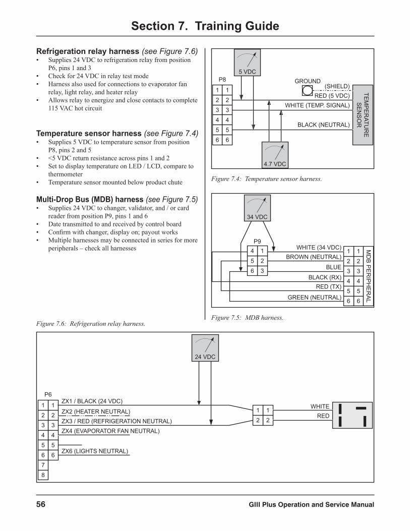
GIII Plus Operation and Service Manual56
Section 7. Training Guide
Refrigeration relay harness (see Figure 7.6)• Supplies 24 VDC to refrigeration relay from position
P6, pins 1 and 3• Check for 24 VDC in relay test mode• Harness also used for connections to evaporator fan
relay, light relay, and heater relay• Allows relay to energize and close contacts to complete
115 VAC hot circuit
Temperature sensor harness (see Figure 7.4)• Supplies 5 VDC to temperature sensor from position
P8, pins 2 and 5• <5 VDC return resistance across pins 1 and 2• Set to display temperature on LED / LCD, compare to
thermometer• Temperature sensor mounted below product chute
Multi-Drop Bus (MDB) harness (see Figure 7.5)• Supplies 24 VDC to changer, validator, and / or card
reader from position P9, pins 1 and 6• Date transmitted to and received by control board• Confirm with changer, display on; payout works• Multiple harnesses may be connected in series for more
peripherals – check all harnesses
P8
TEM
PE
RATU
RE
SE
NS
OR
2
3
4
5
6
1
2
3
4
5
6
1RED (5 VDC)
WHITE (TEMP. SIGNAL)
BLACK (NEUTRAL)
(SHIELD)GROUND
5 VDC
4.7 VDC
Figure 7.4: Temperature sensor harness.
2
3
4
5
6
1
2
3
4
5
6
1 MD
B P
ER
IPH
ER
AL
BROWN (NEUTRAL)
BLUE
RED (TX)
WHITE (34 VDC)
BLACK (RX)
GREEN (NEUTRAL)
2
3
1
5
6
4P9
34 VDC
Figure 7.5: MDB harness.
24 VDC
2
3
4
5
6
1
2
3
4
5
6
1
P6
7
8
2
1
2
1ZX2 (HEATER NEUTRAL)ZX3 / RED (REFRIGERATION NEUTRAL)
ZX1 / BLACK (24 VDC)
ZX4 (EVAPORATOR FAN NEUTRAL)
ZX6 (LIGHTS NEUTRAL)
REDWHITE
Figure 7.6: Refrigeration relay harness.
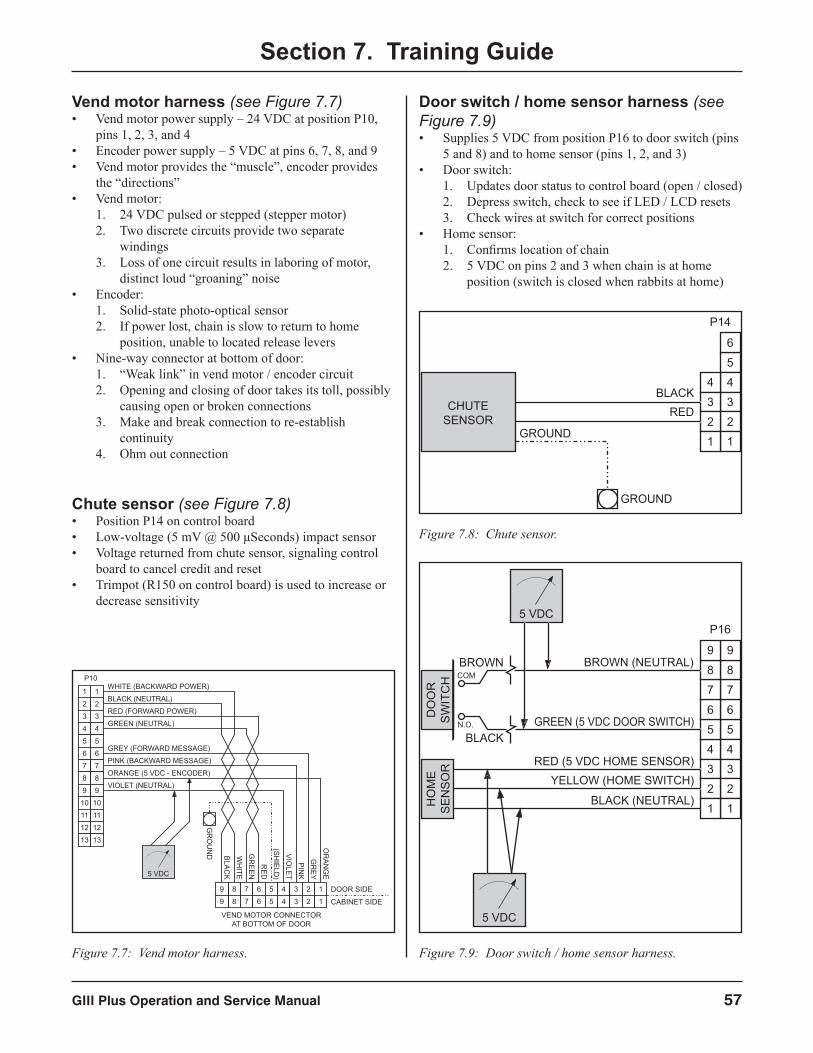
GIII Plus Operation and Service Manual 57
Section 7. Training Guide
Vend motor harness (see Figure 7.7)• Vend motor power supply – 24 VDC at position P10,
pins 1, 2, 3, and 4• Encoder power supply – 5 VDC at pins 6, 7, 8, and 9• Vend motor provides the “muscle”, encoder provides
the “directions”• Vend motor:
1. 24 VDC pulsed or stepped (stepper motor)2. Two discrete circuits provide two separate
windings3. Loss of one circuit results in laboring of motor,
distinct loud “groaning” noise• Encoder:
1. Solid-state photo-optical sensor2. If power lost, chain is slow to return to home
position, unable to located release levers• Nine-way connector at bottom of door:
1. “Weak link” in vend motor / encoder circuit2. Opening and closing of door takes its toll, possibly
causing open or broken connections3. Make and break connection to re-establish
continuity4. Ohm out connection
Chute sensor (see Figure 7.8)• Position P14 on control board• Low-voltage (5 mV @ 500 μSeconds) impact sensor• Voltage returned from chute sensor, signaling control
board to cancel credit and reset• Trimpot (R150 on control board) is used to increase or
decrease sensitivity
Door switch / home sensor harness (see Figure 7.9)• Supplies 5 VDC from position P16 to door switch (pins
5 and 8) and to home sensor (pins 1, 2, and 3)• Door switch:
1. Updates door status to control board (open / closed)2. Depress switch, check to see if LED / LCD resets3. Check wires at switch for correct positions
• Home sensor:1. Confirms location of chain2. 5 VDC on pins 2 and 3 when chain is at home
position (switch is closed when rabbits at home)
4
4
3
3
2
2
1
1
2
3
4
5
6
1
2
3
4
5
6
1
P10
7
8
7
8
9
10
11
12
13
9
10
11
12
13
WHITE (BACKWARD POWER)
BLACK (NEUTRAL)
RED (FORWARD POWER)
GREEN (NEUTRAL)
GREY (FORWARD MESSAGE)
PINK (BACKWARD MESSAGE)
ORANGE (5 VDC - ENCODER)
VIOLET (NEUTRAL)
8
8
7
7
6
6
5
5
9
9
OR
ANG
E
PINK
VIOLET
RED
GR
EEN
WH
ITE
BLACK
GR
EY
(SHIELD
)5 VDC
GR
OU
ND
DOOR SIDE
CABINET SIDE
VEND MOTOR CONNECTORAT BOTTOM OF DOOR
Figure 7.7: Vend motor harness.
P14
5
4
3
2
1
6
4
3
2
1
BLACKREDCHUTE
SENSOR
GROUND
GROUND
Figure 7.8: Chute sensor.
5
4
3
2
1
6
4
3
2
1
RED (5 VDC HOME SENSOR)YELLOW (HOME SWITCH)
HO
ME
SE
NS
OR
5
6
7
8
7
8
P16
99
BLACK (NEUTRAL)
GREEN (5 VDC DOOR SWITCH)
BROWN (NEUTRAL)
DO
OR
SW
ITC
H
BROWN
BLACK
5 VDC
5 VDC
COM
N.O.
Figure 7.9: Door switch / home sensor harness.
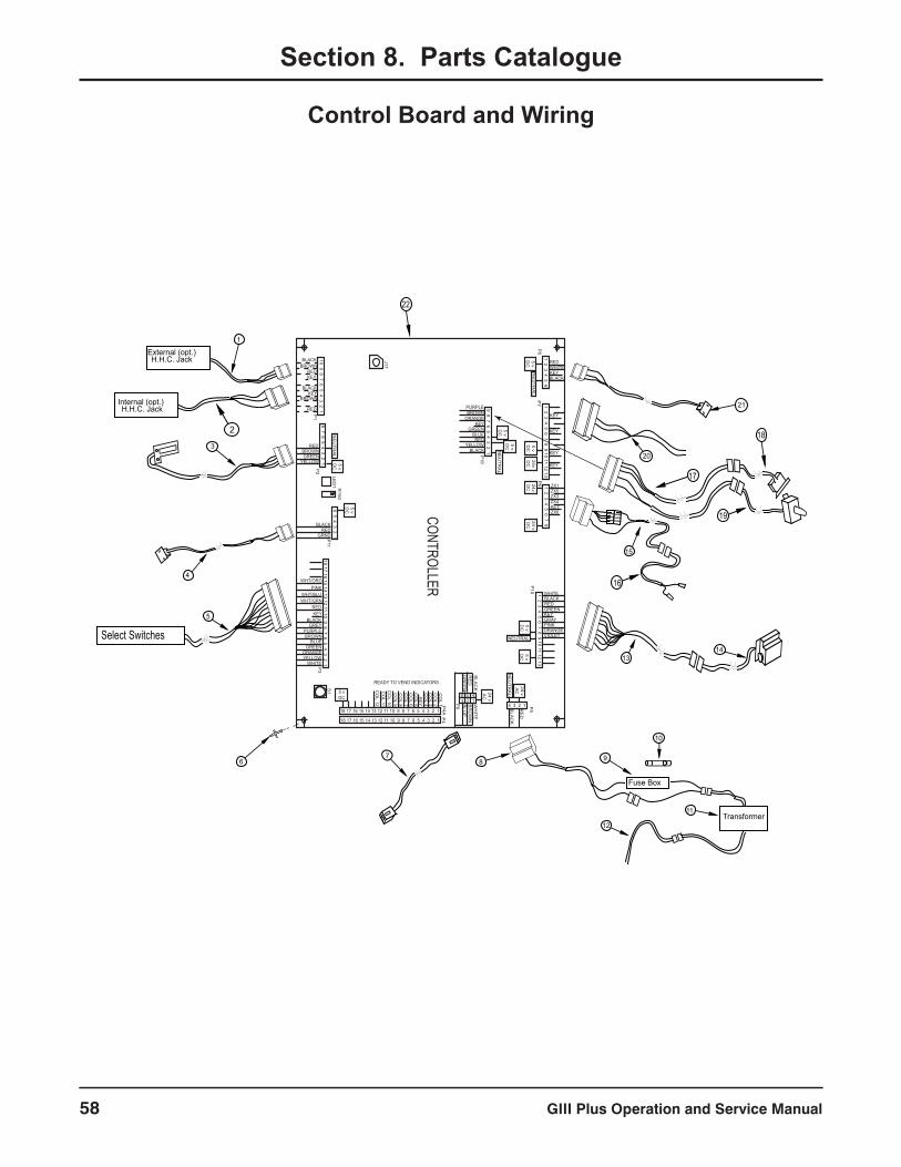
GIII Plus Operation and Service Manual58
Section 8. Parts Catalogue
Control Board and Wiring
1 2 3 4 5 6REDWHITEKEYBLACK
1 2 3 4 5 6 7 8 9 10 11 12 13
KEY
KEY
KEY
KEY
1 2 3 4 5 6 7 8
ZX1ZX5ZX3ZX4
ZX6KEY
1 2 3 4 5 6 7 8 9 10 11 12 13
WHITEBLACKREDGREENKEYGRAYPINKORANGEVIOLET
10 9 8 7 6 5 4 3 2 1
BLACKBROWN
REDKEY
BLACKKEY
RED
BROWN
8 7 6 5 4 3 2 1YELLOWGREEN
BROWNRED
18 17 16 15 14 13 12 11 10 9 8 7 6 5 4 3 2 1
GREYBLACK
KEYRED
6 5 4 3 2 1GRNDRED
BLACK
WHT/GRNWHT/BLU
PINKWHT/ORG
WHITEYELLOWORANGE
GREEN
PURPLE
BLUEBROWN
18 17 16 15 14 13 12 11 10 9 8 7 6 5 4 3 2 1
CO
L 1
18 17 16 15 14 13 12 11 10 9 8 7 6 5 4 3 2 1
CO
L 2C
OL 3
CO
L 4K
EY
CO
L 5C
OL 6
CO
L 7C
OL 8
CO
L 9C
OL 10
CO
L 11C
OL 12 4 3 2 1B
LAC
K
RE
D
NE
UTR
AL
24 vA
C
P5
5 vD
C
NEUTRAL
5 vD
C
5 vDC
P3
P11
5 vD
C5 vD
CP2
P1
NE
UTR
AL
NE
UTR
AL
5 vD
C
P8
P7
5 vD
C24vD
C24vD
C24 vD
C
P6
P10
6 53
42 1
24 vA
C
P4A
P4
P9
READY TO VEND INDICATORS
LED
1 R150
J17
9 8 7 6 5 4 3 2 1PURPLEBROWN
ORANGE
GREENBLUERED
YELLOW
P16
KEY
BLACK
5 vD
C
5 vD
C
NE
UTR
AL
CONTROLLER
S1
BLA
CK
RE
DG
RE
EN
WH
ITEB
RO
WN
BLU
E
Select Switches
External (opt.)H.H.C. Jack
Fuse Box
Transformer
21
13
1
3
5
4
8
14
11
12
9
10
6
20
15
17
18
19
2
Internal (opt.)H.H.C. Jack
7
16
22
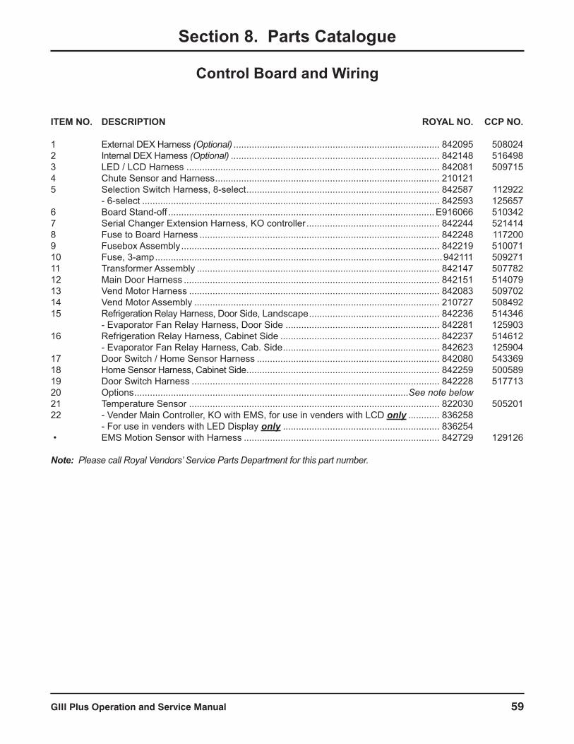
GIII Plus Operation and Service Manual 59
Section 8. Parts Catalogue
Control Board and Wiring
ITEM NO. DESCRIPTION ROYAL NO. CCP NO.
1 External DEX Harness (Optional) ............................................................................... 842095 5080242 Internal DEX Harness (Optional) ................................................................................ 842148 5164983 LED / LCD Harness ................................................................................................. 842081 5097154 Chute Sensor and Harness ...................................................................................... 210121 5 Selection Switch Harness, 8-select .......................................................................... 842587 112922 - 6-select .................................................................................................................. 842593 1256576 Board Stand-off ......................................................................................................E916066 5103427 Serial Changer Extension Harness, KO controller ................................................... 842244 5214148 Fuse to Board Harness ............................................................................................ 842248 1172009 Fusebox Assembly ................................................................................................... 842219 51007110 Fuse, 3-amp ..............................................................................................................942111 50927111 Transformer Assembly ............................................................................................. 842147 50778212 Main Door Harness .................................................................................................. 842151 51407913 Vend Motor Harness ................................................................................................ 842083 50970214 Vend Motor Assembly .............................................................................................. 210727 50849215 Refrigeration Relay Harness, Door Side, Landscape .................................................. 842236 514346 - Evaporator Fan Relay Harness, Door Side ........................................................... 842281 12590316 Refrigeration Relay Harness, Cabinet Side ............................................................. 842237 514612 - Evaporator Fan Relay Harness, Cab. Side ............................................................ 842623 12590417 Door Switch / Home Sensor Harness ...................................................................... 842080 54336918 Home Sensor Harness, Cabinet Side .......................................................................... 842259 50058919 Door Switch Harness ............................................................................................... 842228 51771320 Options .........................................................................................................See note below21 Temperature Sensor ................................................................................................ 822030 50520122 - Vender Main Controller, KO with EMS, for use in venders with LCD only ............ 836258 - For use in venders with LED Display only ............................................................ 836254 • EMS Motion Sensor with Harness ........................................................................... 842729 129126
Note: Please call Royal Vendors’ Service Parts Department for this part number.
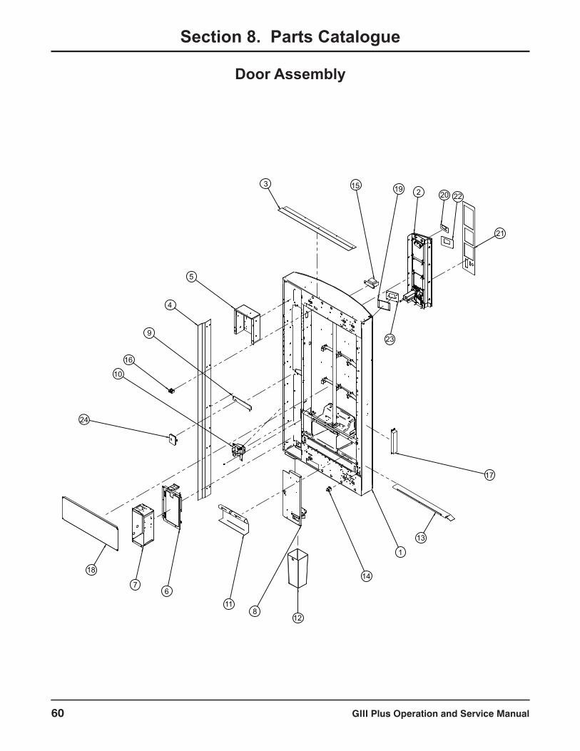
GIII Plus Operation and Service Manual60
Section 8. Parts Catalogue
Door Assembly
5
1
2
8
9
19
6
3
4
11
7
10
18
12
20
14
17
15
16
21
13
23
24
22
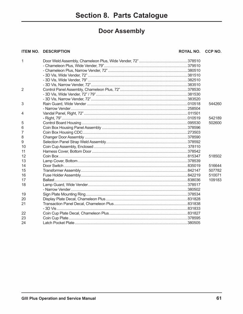
GIII Plus Operation and Service Manual 61
Section 8. Parts Catalogue
Door Assembly
ITEM NO. DESCRIPTION ROYAL NO. CCP NO.
1 Door Weld Assembly, Chameleon Plus, Wide Vender, 72” ................................................378510 - Chameleon Plus, Wide Vender, 79” ...................................................................................379510 - Chameleon Plus, Narrow Vender, 72” ...............................................................................380510 - 3D Vis, Wide Vender, 72” ...................................................................................................381510 - 3D Vis, Wide Vender, 79” ...................................................................................................382510 - 3D Vis, Narrow Vender, 72” ................................................................................................383510 2 Control Panel Assembly, Chameleon Plus, 72” ...................................................................378530 - 3D Vis, Wide Vender, 72” / 79” ...........................................................................................381530 - 3D Vis, Narrow Vender, 72” ................................................................................................383520 3 Rain Guard, Wide Vender ....................................................................................................010518 544260 - Narrow Vender ....................................................................................................................258504 4 Vandal Panel, Right, 72” .......................................................................................................011501 - Right, 79” .............................................................................................................................010519 5421895 Control Board Housing .........................................................................................................095530 5026006 Coin Box Housing Panel Assembly .....................................................................................378596 7 Coin Box Housing CDC ........................................................................................................273503 8 Changer Door Assembly ......................................................................................................378590 9 Selection Panel Strap Weld Assembly .................................................................................378592 10 Coin Cup Assembly, Enclosed .............................................................................................378110 11 Harness Cover, Bottom Door ...............................................................................................378542 12 Coin Box ................................................................................................................................815347 51850213 Lamp Cover, Bottom .............................................................................................................378539 14 Door Switch ...........................................................................................................................835019 51664415 Transformer Assembly ..........................................................................................................842147 50778216 Fuse Holder Assembly ..........................................................................................................842219 51007117 Ballast ....................................................................................................................................838036 10918318 Lamp Guard, Wide Vender ...................................................................................................378517 - Narrow Vender ....................................................................................................................38050219 Sign Plate Mounting Ring .....................................................................................................378534 20 Display Plate Decal, Chameleon Plus .................................................................................831828 21 Transaction Panel Decal, Chameleon Plus .........................................................................831838 - 3D Vis ..................................................................................................................................831833 22 Coin Cup Plate Decal, Chameleon Plus ..............................................................................831827 23 Coin Cup Plate ......................................................................................................................378595 24 Latch Pocket Plate ................................................................................................................380505
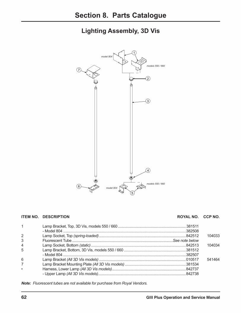
GIII Plus Operation and Service Manual62
Section 8. Parts Catalogue
Lighting Assembly, 3D Vis
1
2
3
4
5
6
7
model 804
models 550 / 660
models 550 / 660
model 804
ITEM NO. DESCRIPTION ROYAL NO. CCP NO.
1 Lamp Bracket, Top, 3D Vis, models 550 / 660 ....................................................................381511 - Model 804 ...........................................................................................................................382508 2 Lamp Socket, Top (spring-loaded) .......................................................................................842512 1040333 Fluorescent Tube .....................................................................................................See note below4 Lamp Socket, Bottom (static) ...............................................................................................842513 1040345 Lamp Bracket, Bottom, 3D Vis, models 550 / 660 ..............................................................381512 - Model 804 ...........................................................................................................................382507 6 Lamp Bracket (All 3D Vis models) .......................................................................................010517 5414647 Lamp Bracket Mounting Plate (All 3D Vis models) .............................................................381534 • Harness, Lower Lamp (All 3D Vis models) ..........................................................................842737 - Upper Lamp (All 3D Vis models)........................................................................................842738
Note: Fluorescent tubes are not available for purchase from Royal Vendors.

GIII Plus Operation and Service Manual 63
Section 8. Parts Catalogue
Lighting Assembly, Chameleon ADA
1
2
3
4
5
4
6
7
2
CHAMELEON ADA MODELS 660 AND 804
ITEM NO. DESCRIPTION ROYAL NO. CCP NO.
1 Lamp Bracket, Top, 660 Chameleon ................381511 - 804 Chameleon ..............................................3825082 Lamp Socket, Top (spring-loaded) ................... 842512 1040333 Fluorescent Tube .................................See note below4 Lamp Socket, Bottom (static) ........................... 842513 1040345 Lamp Bracket, Bottom, 660 Chameleon ......... 381512 - 804 Chameleon ..............................................3825076 Bottom Lamp Panel ..........................................3785167 Bottom Lamp Bracket ....................................... 378538 • Harness, Lower Lamp (All wide Cham ADA) .. 842754 - Upper Lamp (All wide Cham ADA) ................ 842755
Note: Fluorescent tubes are not available for purchase from Royal Vendors.
CHAMELEON ADA MODEL 550
ITEM NO. DESCRIPTION ROYAL NO. CCP NO.
1 Lamp Panel, Chameleon, Narrow .................... 380501 2 Lamp Bracket .................................................... 010517 5414643 Lamp Socket, Top (spring-loaded) ................... 842512 1040334 Fluorescent Tube .................................See note below5 Lamp Socket, Bottom (static) ........................... 842513 1040346 Lamp Bracket, Right, Chameleon Narrow ....... 369525
Note: Fluorescent tubes are not available for purchase from Royal Vendors.
1
2
3
4
6
5

GIII Plus Operation and Service Manual64
Section 8. Parts Catalogue
Control Panel Assembly
12
9
10
1
2
1615
18
11
3
19
6
5
417
13
7
14
8
21
20
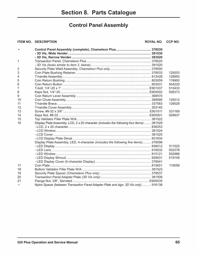
GIII Plus Operation and Service Manual 65
Section 8. Parts Catalogue
Control Panel Assembly
ITEM NO. DESCRIPTION ROYAL NO. CCP NO.
• Control Panel Assembly (complete), Chameleon Plus ....................................... 378530 - 3D Vis, Wide Vender ............................................................................................ 381530 - 3D Vis, Narrow Vender ......................................................................................... 383520 1 Transaction Panel, Chameleon Plus ........................................................................ 378520 - 3D Vis (looks similar to item 2, below) ................................................................... 381520 2 Security Plate Weld Assembly, Chameleon Plus only .............................................. 378550 3 Coin Plate Bushing Retainer .................................................................................... 378533 1292034 T-handle Assembly ................................................................................................... 812428 1289505 Coin Return Bushing ................................................................................................ 803059 1199006 Coin Return Button .................................................................................................. 803031 5042297 T-bolt, 1/4”-20 x 1” ..................................................................................................E901037 5104338 Keps Nut, 1/4”-20 ...................................................................................................E905002 5083739 Coin Return Lever Assembly ................................................................................... 369570 10 Coin Chute Assembly ............................................................................................... 369580 12931211 T-handle Brace ......................................................................................................... 337583 12902812 T-handle Cover Assembly ........................................................................................ 303145 13 Screw, #8-32 x 3/8” ................................................................................................ E901011 53116914 Keps Nut, #8-32 .....................................................................................................E905001 50993715 Top Validator Filler Plate W/A ................................................................................... 381522 16 Display Plate Assembly, LCD, 2 x 20 character (includes the following four items) ........ 381529 - LCD, 2 x 20 character ............................................................................................ 836253 - LCD Window .......................................................................................................... 381524 - LCD Cover ............................................................................................................. 381525 - LCD Display Plate Decal ....................................................................................... 831834 Display Plate Assembly, LED, 4-character (includes the following five items) ......... 378598 - LED Display ........................................................................................................... 836012 511525 - LED Lens ............................................................................................................... 916032 502378 - LED Window .......................................................................................................... 815121 502988 - LED Display Shroud .............................................................................................. 929031 519108 - LED Display Cover (4-character Display) .............................................................. 378541 17 Coin Plate ................................................................................................................ 815651 11905818 Bottom Validator Filler Plate W/A ............................................................................. 381523 19 Security Plate Spacer (Chameleon Plus only) ......................................................... 378537 20 Transaction Panel Adapter Plate (3D Vis only) ........................................................ 38150821 Flange Nut, 3/8”, Serrated ..................................................................................... E905035 • Nylon Spacer (between Transaction Panel Adapter Plate and sign, 3D Vis only) .......... 916138

GIII Plus Operation and Service Manual66
Section 8. Parts Catalogue
Port Assembly
1
2
3
413
67
8
9 10
11
12
7
5
9
8
ITEM NO. DESCRIPTION ROYAL NO. CCP NO.
1 Bottle Stop, Chameleon ........................................................................................................273508 520049 - 3D Vis ..................................................................................................................................381507 2 Port Trim, Chameleon only ...................................................................................................815249 5200503 Port Spacer, Chameleon only ..............................................................................................815248 5200514 Port Body Weld Assembly ....................................................................................................378540 5 Anti-theft Plate .......................................................................................................................378521 6 Keps Nut, #8-32 ................................................................................................................. E905001 5099377 Port Brace, Wide Vender ......................................................................................................369524 - Narrow Vender ....................................................................................................................3805038 Keps Nut, 1/4”-20 ............................................................................................................... E905002 5083739 Carriage Bolt, 1/4”-20 x 1/2” .............................................................................................. E901007 50804610 Screw, #8-32 x 3/8” .............................................................................................................E901011 53116911 Burst-open Latch ...................................................................................................................912003 12 Latch Roller Bracket ..............................................................................................................010516 50571113 EMS Motion Sensor with Harness .......................................................................................842729 129126
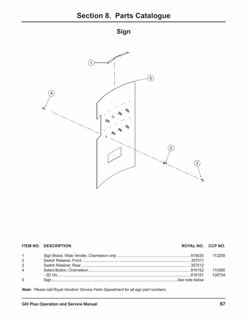
GIII Plus Operation and Service Manual 67
Section 8. Parts Catalogue
Sign
ITEM NO. DESCRIPTION ROYAL NO. CCP NO.
1 Sign Brace, Wide Vender, Chameleon only ........................................................................815635 1132582 Switch Retainer, Front ..........................................................................................................357511 3 Switch Retainer, Rear ...........................................................................................................357512 4 Select Button, Chameleon ....................................................................................................816152 110385 - 3D Vis ..................................................................................................................................816181 1287545 Sign ...........................................................................................................................See note below
Note: Please call Royal Vendors’ Service Parts Department for all sign part numbers.
1
2
3
4
5
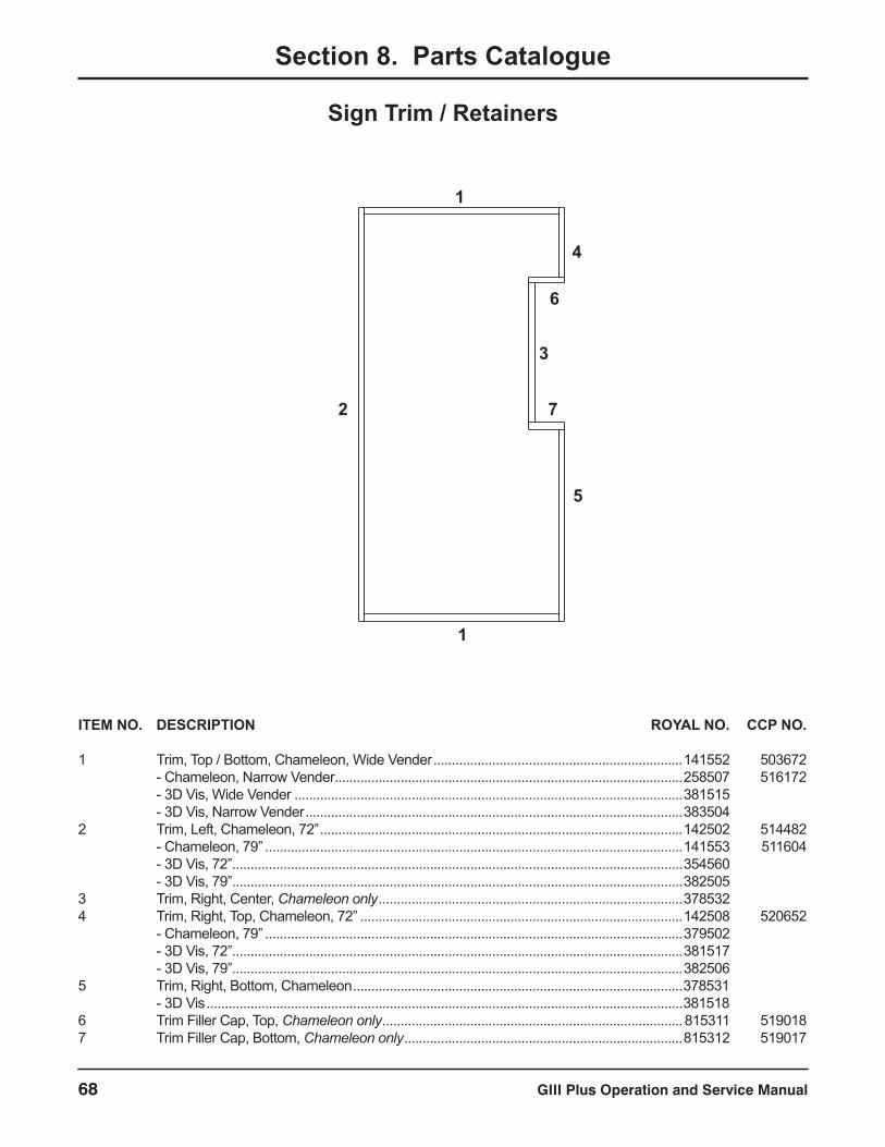
GIII Plus Operation and Service Manual68
Section 8. Parts Catalogue
Sign Trim / Retainers
1
2 7
1
6
3
5
4
ITEM NO. DESCRIPTION ROYAL NO. CCP NO.
1 Trim, Top / Bottom, Chameleon, Wide Vender ....................................................................141552 503672 - Chameleon, Narrow Vender...............................................................................................258507 516172 - 3D Vis, Wide Vender ..........................................................................................................381515 - 3D Vis, Narrow Vender .......................................................................................................383504 2 Trim, Left, Chameleon, 72” ...................................................................................................142502 514482 - Chameleon, 79” ..................................................................................................................141553 511604 - 3D Vis, 72” ...........................................................................................................................354560 - 3D Vis, 79” ...........................................................................................................................382505 3 Trim, Right, Center, Chameleon only ...................................................................................378532 4 Trim, Right, Top, Chameleon, 72” ........................................................................................142508 520652 - Chameleon, 79” ..................................................................................................................379502 - 3D Vis, 72” ...........................................................................................................................381517 - 3D Vis, 79” ...........................................................................................................................382506 5 Trim, Right, Bottom, Chameleon ..........................................................................................378531 - 3D Vis ..................................................................................................................................3815186 Trim Filler Cap, Top, Chameleon only ..................................................................................815311 5190187 Trim Filler Cap, Bottom, Chameleon only ............................................................................815312 519017
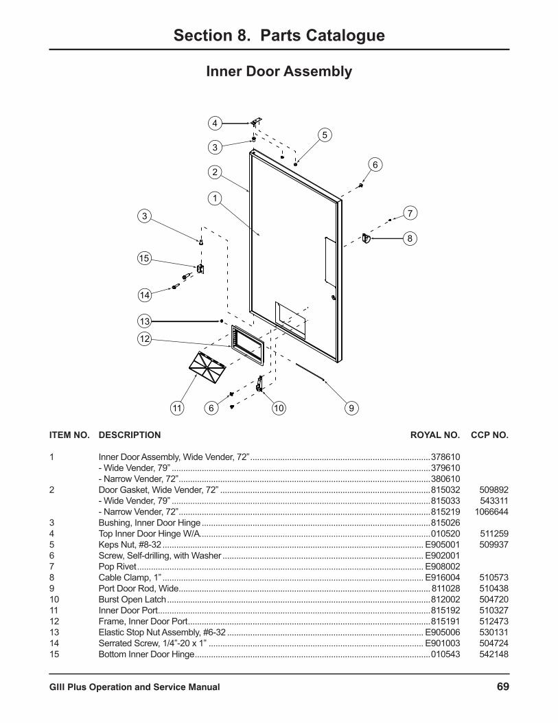
GIII Plus Operation and Service Manual 69
Section 8. Parts Catalogue
2
1
3
45
6
7
8
910611
12
13
14
15
3
ITEM NO. DESCRIPTION ROYAL NO. CCP NO.
1 Inner Door Assembly, Wide Vender, 72” ..............................................................................378610 - Wide Vender, 79” ................................................................................................................379610 - Narrow Vender, 72” .............................................................................................................380610 2 Door Gasket, Wide Vender, 72” ...........................................................................................815032 509892 - Wide Vender, 79” ................................................................................................................815033 543311 - Narrow Vender, 72” .............................................................................................................815219 10666443 Bushing, Inner Door Hinge ...................................................................................................815026 4 Top Inner Door Hinge W/A ....................................................................................................010520 5112595 Keps Nut, #8-32 ................................................................................................................. E905001 5099376 Screw, Self-drilling, with Washer ....................................................................................... E902001 7 Pop Rivet ............................................................................................................................ E908002 8 Cable Clamp, 1” ................................................................................................................. E916004 5105739 Port Door Rod, Wide .............................................................................................................811028 51043810 Burst Open Latch ..................................................................................................................812002 50472011 Inner Door Port ......................................................................................................................815192 51032712 Frame, Inner Door Port .........................................................................................................815191 51247313 Elastic Stop Nut Assembly, #6-32 ..................................................................................... E905006 53013114 Serrated Screw, 1/4”-20 x 1” ............................................................................................. E901003 50472415 Bottom Inner Door Hinge ......................................................................................................010543 542148
Inner Door Assembly
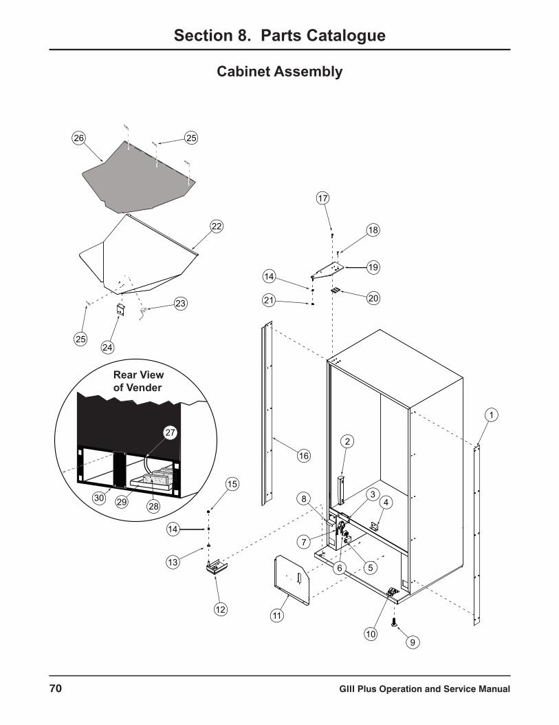
GIII Plus Operation and Service Manual70
Cabinet Assembly
Section 8. Parts Catalogue
Rear View of Vender
27
282930
1
910
11
2
34
56
7
8
16
12
15
13
14
17
18
19
2021
14
22
23
2425
26 25
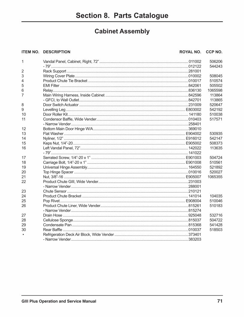
GIII Plus Operation and Service Manual 71
ITEM NO. DESCRIPTION ROYAL NO. CCP NO.
1 Vandal Panel, Cabinet, Right, 72” ........................................................................................011002 506206 - 79” ........................................................................................................................................012122 5442432 Rack Support ........................................................................................................................281001 3 Wiring Cover Plate ................................................................................................................010002 5080454 Product Chute Tie Bracket ...................................................................................................010017 5105745 EMI Filter ...............................................................................................................................842061 5055026 Relay ......................................................................................................................................836130 10655987 Main Wiring Harness, Inside Cabinet ..................................................................................842596 113864 - GFCI, to Wall Outlet ............................................................................................................842701 1138658 Door Switch Actuator ............................................................................................................231009 5206479 Levelling Leg ...................................................................................................................... E803002 54219210 Door Roller Kit .......................................................................................................................141180 51003811 Condensor Baffle, Wide Vender ...........................................................................................010403 517571 - Narrow Vender ....................................................................................................................258401 12 Bottom Main Door Hinge W/A ..............................................................................................369010 13 Flat Washer ........................................................................................................................ E904002 53093514 Nyliner, 1/2” ........................................................................................................................ E916012 54214715 Keps Nut, 1/4”-20 ............................................................................................................... E905002 50837316 Left Vandal Panel, 72”...........................................................................................................142022 113635 - 79” ........................................................................................................................................141022 17 Serrated Screw, 1/4”-20 x 1” ............................................................................................. E901003 50472418 Carriage Bolt, 1/4”-20 x 1” ................................................................................................. E901008 51056119 Universal Hinge Assembly ....................................................................................................164550 52189220 Top Hinge Spacer .................................................................................................................010016 52002721 Nut, 3/8”-16 ........................................................................................................................ E905007 106535522 Product Chute GIII, Wide Vender .........................................................................................231003 - Narrow Vender ....................................................................................................................288001 23 Chute Sensor ........................................................................................................................210121 24 Product Chute Bracket .........................................................................................................141014 10403525 Pop Rivet ............................................................................................................................ E908004 51004626 Product Chute Liner, Wide Vender .......................................................................................815261 510183 - Narrow Vender ....................................................................................................................815274 27 Drain Hose ............................................................................................................................925048 53271628 Cellulose Sponge ..................................................................................................................815037 50472229 Condensate Pan ...................................................................................................................815368 54142830 Rear Baffle ............................................................................................................................010037 518503 • Refrigeration Deck Air Block, Wide Vender .........................................................................373401 - Narrow Vender ....................................................................................................................383203
Section 8. Parts Catalogue
Cabinet Assembly
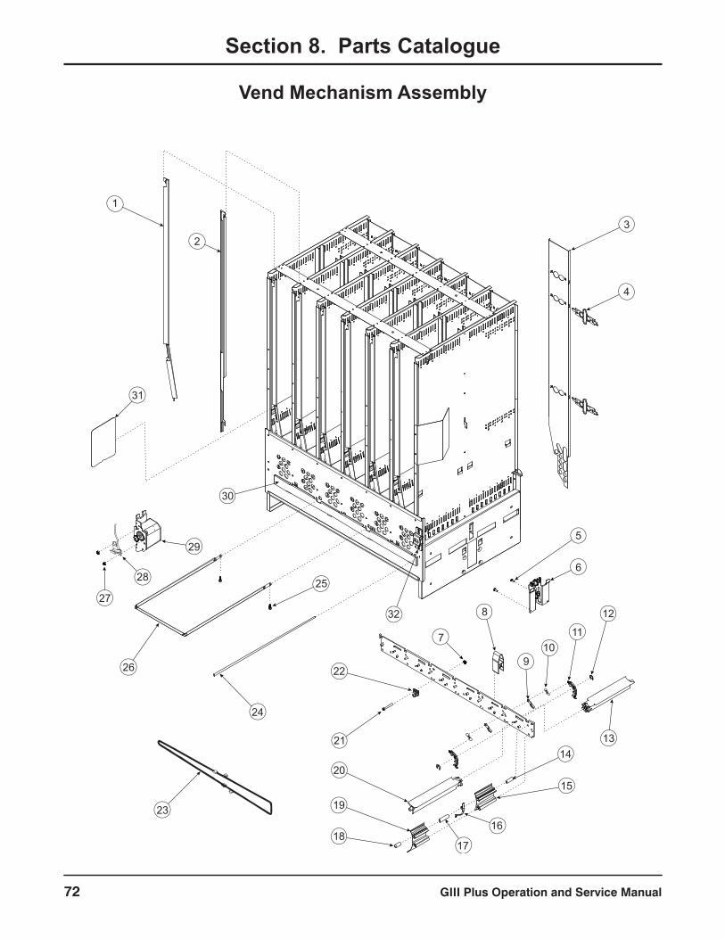
GIII Plus Operation and Service Manual72
Vend Mechanism Assembly
1
23
4
6
5
7
8
910
11
12
1314
15
16
1718
19
20
21
22
23
24
25
26
27
28
29
30
31
32
Section 8. Parts Catalogue

GIII Plus Operation and Service Manual 73
Vend Mechanism Assembly
ITEM NO. DESCRIPTION ROYAL NO. CCP NO.
1 Retainer, Front, Left, 72” .......................................................................................................211712 509315 - Left, 79” ...............................................................................................................................210745 5091272 Retainer, Front, Right, 72” ....................................................................................................211713 510842 - Right, 79” .............................................................................................................................210746 5091263 Retainer Assembly, Rear, 72” ...............................................................................................211714 510507 - Rear, 79” ..............................................................................................................................210749 5222254 Retainer Spring Finger ..........................................................................................................815251 5143135 Screw, #8-32 x 3/8” .............................................................................................................E901011 5311696 Idler Bracket Assembly GIII+ ................................................................................................210757 5170937 Keps Nut, #6-32 ................................................................................................................. E905018 10671508 Insert Divider GIII+ ................................................................................................................815252 5184269 Pivot Pawl ..............................................................................................................................915188 50860110 Extension Spring ...................................................................................................................914008 50124511 Release Lever .......................................................................................................................915125 50117612 Retaining Ring, 1/4” ........................................................................................................... E906013 50117313 Pivot, Rear .............................................................................................................................815404 50978114 Spacer, 1.25” .........................................................................................................................915182 50880815 Adjustable Product Stop, Short ............................................................................................813006 51362416 Anti-tilt Spring ........................................................................................................................915186 53013617 Spacer, 1.85” .........................................................................................................................915250 51043618 Spacer, 1.00” .........................................................................................................................915264 52304319 Adjustable Product Stop, Long .............................................................................................813016 51157620 Pivot, Front ............................................................................................................................815403 50978021 Machine Screw, #6-32 x 1.25” ........................................................................................... E901041 95895022 Chain Stabilizer .....................................................................................................................915266 51709123 Chain Assembly, Wide Vender .............................................................................................210730 509270 - Narrow Vender ....................................................................................................................283710 51857524 Pivot Rod ...............................................................................................................................803032 50981225 Screw, Self-drilling .............................................................................................................. E902004 54429426 Case Support ........................................................................................................................811026 52036727 Elastic Stop Nut Assembly, #6-32 ..................................................................................... E905006 53013128 Home Sensor ........................................................................................................................842259 50058929 Vend Motor Assembly, GIII ...................................................................................................210727 50849230 Rod Retainer, GIII+, Wide Vender........................................................................................281709 519907 - Narrow Vender ....................................................................................................................283704 52062131 Anti-friction Sheet ..................................................................................................................915197 51277632 Latch Strike Assembly, Chameleon Plus .............................................................................378010
Section 8. Parts Catalogue
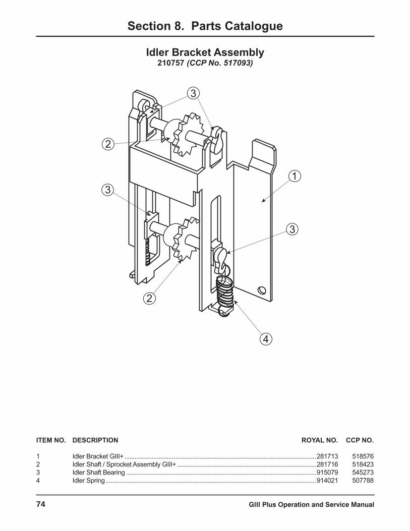
GIII Plus Operation and Service Manual74
Idler Bracket Assembly210757 (CCP No. 517093)
Section 8. Parts Catalogue
3
2
1
3
4
2
3
ITEM NO. DESCRIPTION ROYAL NO. CCP NO.
1 Idler Bracket GIII+ .................................................................................................................281713 5185762 Idler Shaft / Sprocket Assembly GIII+ ..................................................................................281716 5184233 Idler Shaft Bearing ................................................................................................................915079 5452734 Idler Spring ............................................................................................................................914021 507788
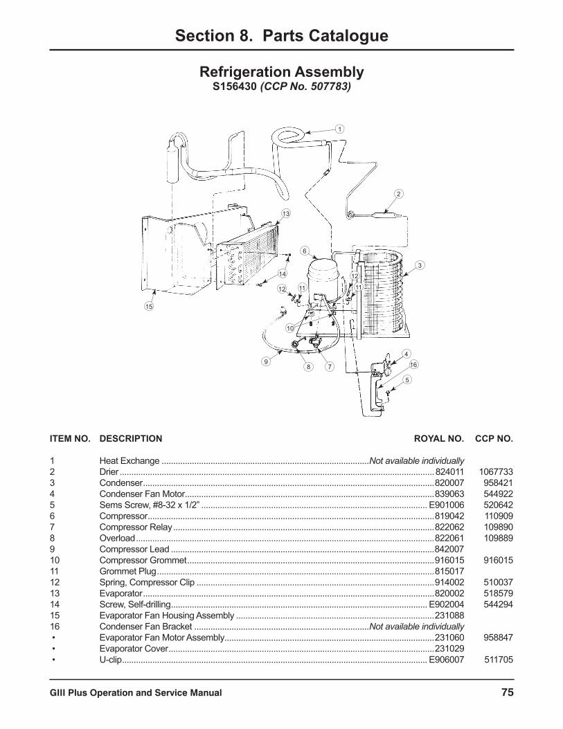
GIII Plus Operation and Service Manual 75
Refrigeration AssemblyS156430 (CCP No. 507783)
Section 8. Parts Catalogue
2
3
4
513OPTIONAL
98 7
10
12 11 11
1214
13
15
6
16
1
ITEM NO. DESCRIPTION ROYAL NO. CCP NO.
1 Heat Exchange .........................................................................................Not available individually2 Drier .......................................................................................................................................824011 10677333 Condenser .............................................................................................................................820007 9584214 Condenser Fan Motor ...........................................................................................................839063 5449225 Sems Screw, #8-32 x 1/2” ................................................................................................. E901006 5206426 Compressor ...........................................................................................................................819042 1109097 Compressor Relay ................................................................................................................822062 1098908 Overload ................................................................................................................................822061 1098899 Compressor Lead .................................................................................................................84200710 Compressor Grommet ..........................................................................................................916015 91601511 Grommet Plug .......................................................................................................................815017 12 Spring, Compressor Clip ......................................................................................................914002 51003713 Evaporator .............................................................................................................................820002 51857914 Screw, Self-drilling .............................................................................................................. E902004 54429415 Evaporator Fan Housing Assembly .....................................................................................231088 16 Condenser Fan Bracket ...........................................................................Not available individually • Evaporator Fan Motor Assembly ..........................................................................................231060 958847 • Evaporator Cover ..................................................................................................................231029 • U-clip ................................................................................................................................... E906007 511705
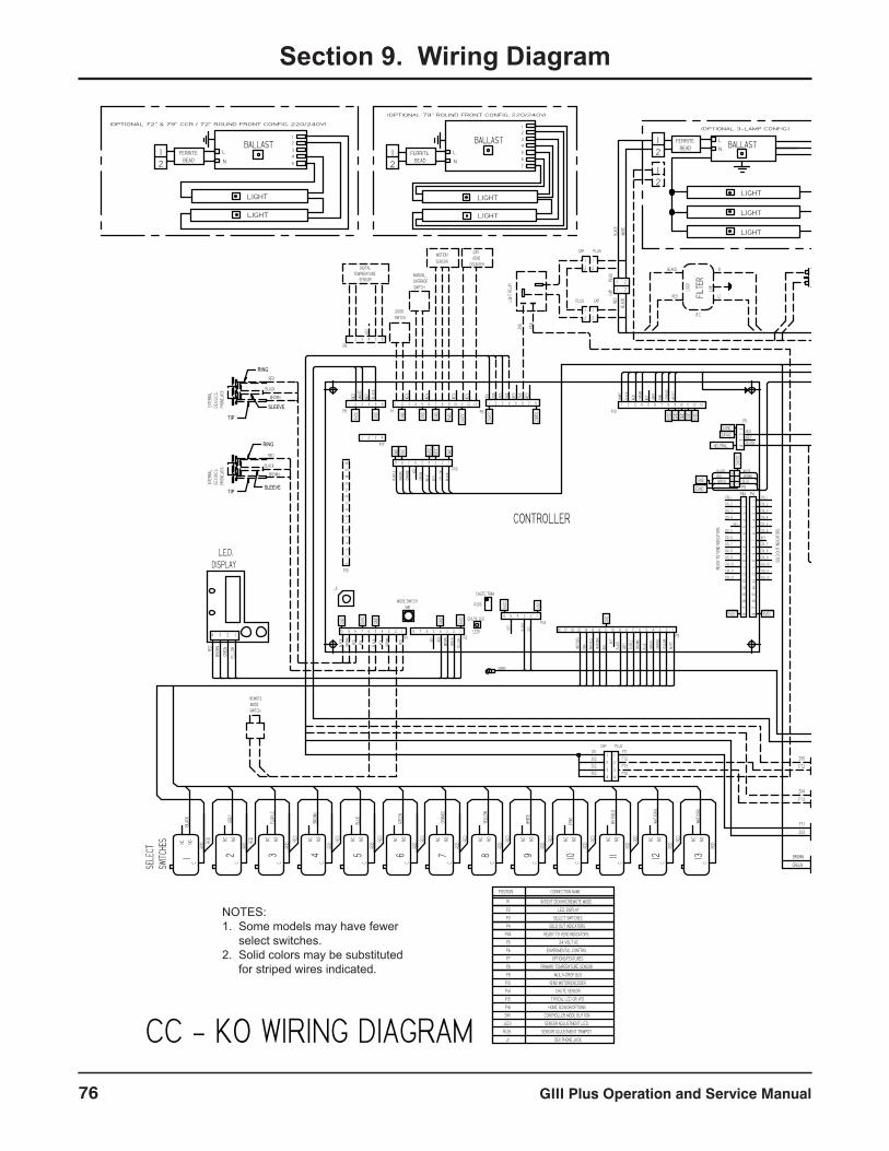
GIII Plus Operation and Service Manual76
Section 9. Wiring Diagram
FERRITEBEAD
FERRITEBEAD
FERRITEBEAD
APPLICABLE PLUG FOR DESTINATION COUNTRY
110/120VAC 220/240VAC
SINGLE PHASE W/EARTHPOWER IN
EVAPORATORFAN RELAY
TEMP SENSOR
MOTION SENSOR
LIGH
TS
FERRITEBEAD
NEUTRAL
CONTROLLER
BLAC
K
WHITE
RED
WHT/
ORG
PINK
WHT/
BLU
WHT/
GRN
3
2
1RED
BLACK
BROWN
RED
BLACK
YELLOW3
2
1
RED
BLACK
BROWN 3
2
1
HOMESENSOR
BLAC
K
RED
DOORSWITCH
BLAC
K
PURP
LE
BROW
N
ORAN
GE
GREE
N
BLUE
ENCODER
MOTOR
5
4
3
2
1
6
5
4
3
2
1
GREY
ORANGE
PINK
PURPLE
GREEN
BLACK
WHITE
RED
GROUND GROUND
BLACK BLACK
WHITE WHITE
GREEN GREEN
RED RED
ORANGE ORANGE
GREY GREY
PINK PINK
PURPLE PURPLE
9
8
7
6
5
4
3
2
1
9
8
7
6
5
4
3
2
1
CAPPLUG
WHITE
YELL
OW
ORAN
GE
GREE
N
BLUE
BROW
N
PURP
LE
GREY
BLAC
K
18 14151617
REMOTE MODESWITCH
COL 12COL 12
COL 11COL 11
COL 10COL 10
COL 9COL 9
COL 8COL 8
COL 7COL 7
COL 6
KEY COL 5
COL 6 KEY
COL 5
COL 4COL 4
COL 3COL 3
COL 2COL 2
COL 1COL 1
SOLD
OUT
INDIC
ATOR
S
READ
Y TO
VEN
D IND
ICATO
RS
9
KEY
RED
YELL
OW
P168 7 6 5 4 3 2 1
DIGITALTEMPERATURE
SENSOR
KEY
P8654321
KEY
KEY
KEY
MANUALOVERRIDE SWITCH
MOTIONSENSOR
24V VEND
COUNTER
KEY
KEY
P1
P8 P7 P10
P9P4A P4
SW1
P3
BLACKREDGREEN
WHITEBROWNBLUE
ZX1
ZX5
ZX3
ZX4
KEY
ZX6
WHITE
VIOLE
T
ORAN
GE
PINK
GRAY
KEY
GREE
N
RED
BLAC
K
J1
RED
BROW
N
GREE
N P2
BLAC
K
RED
WHITE
DEX PHONE JACKJ1
HOME SENSOR/OPTIONS
SOLD OUT INDICATORS
READY TO VEND INDICATORS
CHUTE SENSOR
SENSOR ADJUSTMENT TRIMPOT
SENSOR ADJUSTMENT L.E.D.
CONTROLLER MODE BUTTON
R126
LED1
SW1
RECPT PLUG
22
11
COM
NO
NC
220/240v AC
110v AC
EXPORTDOMESTIC
5vDC
BROWN
BLACK
BLACKGREEN
BROWNBROWN
ST2
ST1
ZX3
FT1
FN2
FN1
FT3
ZX4
FT2
ZX5
HT2
HT1
DOORSWITCH
22
2 2
22
11
11
11
CAP
CAP
CAPPLUG
PLUG
PLUG
CHUTE SENSOR
SENSORTEMPERATURE
8765432112 131110987654321654321 12 131110987654321
14
32
32
146
5
1817
1615
149
1011
1213
87
65
43
21
1817
1615
149
1011
1213
87
65
43
21
BLAC
K
BROW
N
RED
KEY
KEY
BLAC
K
BROW
N
RED
910 8 7 6 5 4 3 2 1 8 7 6 5 4 3 2 1
YELL
OW
6 5 4 3 2 1
9101112
9876543 13WH
T/OR
G
RED
NC NOC
12WH
T/GR
N
RED
RED
NC NOC
11WH
T/BL
U
RED
RED
NC NOC
10PIN
K
RED
RED
NC NOC
WHITE
RED
RED
NC NOC
YELL
OW
RED
NC NOC
ORAN
GE
RED
RED
NC NOC
GREE
N
RED
RED
NC NOC
BLUE
RED
RED
NC NOC
BROW
N
RED
RED
NC NOC
21
PURP
LE
RED
RED
NC NOC
GREY
RED
RED
NC NOC
BLAC
K
RED
REDNC NO
C
13 8 7 6 5 4 3 2 1
220/240VACI.E.C.
POWERINTERUPT SWITCH
I.E.C.
I.E.C.
220/
240V
AC (L
INE)
24 V
AC (L
OAD)
24
VOLT
TRAN
SFOR
MER
24v DC
(IEC)
L1
N
RED
BLACK
LINE
LOAD
FILTE
R
L1
N
RED
BLACK
LINE
LOAD
FILTE
R
RED
BLACK123
123
FUSE
BLK
BLK
REDREDPLUGCAP
22
11
RED
KEY
P5
110VA
C (LI
NE)
24 V
AC (L
OAD)
24 VOLT AC
P10
TYPICAL LCD OR VFD
ENVIROMENTAL CONTROL
PRIMARY TEMPERATURE SENSOR
INT/EXT DEX/HHC/REMOTE MODE
OPTIONS/FEATURES
VEND MOTOR/ENCODER
SELECT SWITCHES
MULTI-DROP BUS
L.E.D. DISPLAY
P16
P15
P14
P9
P8
P7
P6
P5
P4A
P4
P3
P2
P1
CONNECTION NAMEPOSITION
L1N
N
L1
BLAC
K
WHITE
BLAC
K
WHITE
HT2
HT1
FN2
FN1
ST2
ST1
BLAC
K
RED
BLK
BLK
REDRED
RED
BLACK
ZX6 FT4
FT4
FT3
FT2
FT1
ZX2
ZX2
ZX2
ZX1
YELL
OW
GREE
N
BROW
N
RED
4 3 2 1
BROWN
BLACK
RED
RED
BLACK
BROWN
HEATER RELAY
HEATER THERMOSTAT
HEATER
220 VOLTTRANSFORMER
1.0 KVA
FAN MOTOREVAPORATOR
COMPRESSORFAN MOTOR
COMPRESSOR
MAIN WIRING HARNESS
REFRIGERATIONRELAY
LINE
LOAD FILTER
SEL
ECT
SWITC
HES
PLUGCAP
CAP PLUG
PLUG
PLUG CAP
CAP
CAP
PLUG
22
11
24
VOLT
TRAN
SFOR
MER
CHANGER VALIDATOR
MULTI-DROP BUS
44
33
22
11
P6
LED1
R126
P14
2
2
22
2 2
1
1
11
11
LIGHT
REL
AY
L.E.D.DISPLAY
INTE
RNAL
D.E.X./
U.C.S.
PHO
NEJA
CK
EXT
ERNA
LD.E
.X./U.C
.S. P
HONE
JACK
GRND
4321
P17
60HZ ONLY
L1
N
L1
N
LOAD
LINE FILTER
I.E.C. / 50HZ ONLY
LINE
LOAD FILTER
I.E.C. / 50HZ ONLY
GND
5VDC
24VD
C
GND
GND
GND
5VDC
24VD
C
24VD
C
KEY
GND
GND
GND
5VDC
5VDC
5VDC
5VDCGND
GND
GND
24VD
C
EGND
KEY
EGND
GND
5VDC 5VDC
GND
GND
KEY
5VDC
5VDC
GND
KEY
GND
GND
5VDC
24VAC
CHUTE LED
MODE SWITCH
CHUTE TRIM
GND
P15
1612
1314
1511
109
87
65
43
21
EMS
RING
SLEEVE
TIP
RING
SLEEVETIP
BALLAST
LIGHT
LIGHT
LIGHT
21
(OPTIONAL 3-LAMP CONFIG.)
BALLAST
LIGHT
LIGHT
L
N
12
34
56
721
(OPTIONAL 79" ROUND FRONT CONFIG. 220/240V)
L
N
(OPTIONAL 72" & 79" CCR / 72" ROUND FRONT CONFIG. 220/240V)
BALLAST
LIGHT
LIGHT
L
N
12
34
521
21
BALLAST
LIGHT
LIGHT
21
(OPTIONAL 2-LAMP CONFIG.)
L
N
NOTES:1. Some models may have fewer select switches.2. Solid colors may be substituted for striped wires indicated.
CC - KO WIRING DIAGRAM
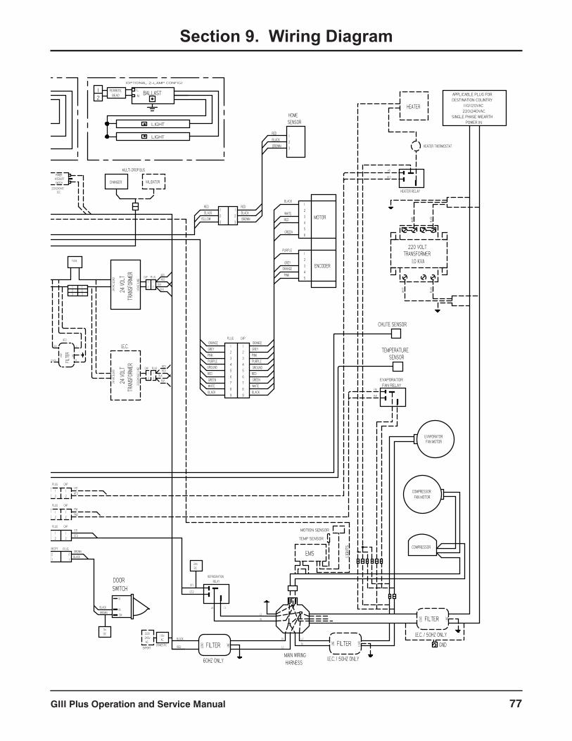
GIII Plus Operation and Service Manual 77
Section 9. Wiring Diagram
FERRITEBEAD
FERRITEBEAD
FERRITEBEAD
APPLICABLE PLUG FOR DESTINATION COUNTRY
110/120VAC 220/240VAC
SINGLE PHASE W/EARTHPOWER IN
EVAPORATORFAN RELAY
TEMP SENSOR
MOTION SENSOR
LIGH
TS
FERRITEBEAD
NEUTRAL
CONTROLLER
BLAC
K
WHITE
RED
WHT/
ORG
PINK
WHT/
BLU
WHT/
GRN
3
2
1RED
BLACK
BROWN
RED
BLACK
YELLOW3
2
1
RED
BLACK
BROWN 3
2
1
HOMESENSOR
BLAC
K
RED
DOORSWITCH
BLAC
K
PURP
LE
BROW
N
ORAN
GE
GREE
N
BLUE
ENCODER
MOTOR
5
4
3
2
1
6
5
4
3
2
1
GREY
ORANGE
PINK
PURPLE
GREEN
BLACK
WHITE
RED
GROUND GROUND
BLACK BLACK
WHITE WHITE
GREEN GREEN
RED RED
ORANGE ORANGE
GREY GREY
PINK PINK
PURPLE PURPLE
9
8
7
6
5
4
3
2
1
9
8
7
6
5
4
3
2
1
CAPPLUG
WHITE
YELL
OW
ORAN
GE
GREE
N
BLUE
BROW
N
PURP
LE
GREY
BLAC
K
18 14151617
REMOTE MODESWITCH
COL 12COL 12
COL 11COL 11
COL 10COL 10
COL 9COL 9
COL 8COL 8
COL 7COL 7
COL 6
KEY COL 5
COL 6 KEY
COL 5
COL 4COL 4
COL 3COL 3
COL 2COL 2
COL 1COL 1
SOLD
OUT
INDIC
ATOR
S
READ
Y TO
VEN
D IND
ICATO
RS
9
KEY
RED
YELL
OW
P168 7 6 5 4 3 2 1
DIGITALTEMPERATURE
SENSOR
KEY
P8654321
KEY
KEY
KEY
MANUALOVERRIDE SWITCH
MOTIONSENSOR
24V VEND
COUNTER
KEY
KEY
P1
P8 P7 P10
P9P4A P4
SW1
P3
BLACKREDGREEN
WHITEBROWNBLUE
ZX1
ZX5
ZX3
ZX4
KEY
ZX6
WHITE
VIOLE
T
ORAN
GE
PINK
GRAY
KEY
GREE
N
RED
BLAC
K
J1
RED
BROW
N
GREE
N P2
BLAC
K
RED
WHITE
DEX PHONE JACKJ1
HOME SENSOR/OPTIONS
SOLD OUT INDICATORS
READY TO VEND INDICATORS
CHUTE SENSOR
SENSOR ADJUSTMENT TRIMPOT
SENSOR ADJUSTMENT L.E.D.
CONTROLLER MODE BUTTON
R126
LED1
SW1
RECPT PLUG
22
11
COM
NO
NC
220/240v AC
110v AC
EXPORTDOMESTIC
5vDC
BROWN
BLACK
BLACKGREEN
BROWNBROWN
ST2
ST1
ZX3
FT1
FN2
FN1
FT3
ZX4
FT2
ZX5
HT2
HT1
DOORSWITCH
22
2 2
22
11
11
11
CAP
CAP
CAPPLUG
PLUG
PLUG
CHUTE SENSOR
SENSORTEMPERATURE
8765432112 131110987654321654321 12 131110987654321
14
32
32
146
5
1817
1615
149
1011
1213
87
65
43
21
1817
1615
149
1011
1213
87
65
43
21
BLAC
K
BROW
N
RED
KEY
KEY
BLAC
K
BROW
N
RED
910 8 7 6 5 4 3 2 1 8 7 6 5 4 3 2 1
YELL
OW
6 5 4 3 2 1
9101112
9876543 13WH
T/OR
G
RED
NC NOC
12WH
T/GR
N
RED
RED
NC NOC
11WH
T/BL
U
RED
RED
NC NOC
10PIN
K
RED
RED
NC NOC
WHITE
RED
RED
NC NOC
YELL
OW
RED
NC NOC
ORAN
GE
RED
RED
NC NOC
GREE
N
RED
RED
NC NOC
BLUE
RED
RED
NC NOC
BROW
N
RED
RED
NC NOC
21
PURP
LE
RED
RED
NC NOC
GREY
RED
RED
NC NOC
BLAC
K
RED
REDNC NO
C
13 8 7 6 5 4 3 2 1
220/240VACI.E.C.
POWERINTERUPT SWITCH
I.E.C.
I.E.C.
220/
240V
AC (L
INE)
24 V
AC (L
OAD)
24
VOLT
TRAN
SFOR
MER
24v DC
(IEC)
L1
N
RED
BLACK
LINE
LOAD
FILTE
R
L1
N
RED
BLACK
LINE
LOAD
FILTE
R
RED
BLACK123
123
FUSE
BLK
BLK
REDREDPLUGCAP
22
11
RED
KEY
P5
110VA
C (LI
NE)
24 V
AC (L
OAD)
24 VOLT AC
P10
TYPICAL LCD OR VFD
ENVIROMENTAL CONTROL
PRIMARY TEMPERATURE SENSOR
INT/EXT DEX/HHC/REMOTE MODE
OPTIONS/FEATURES
VEND MOTOR/ENCODER
SELECT SWITCHES
MULTI-DROP BUS
L.E.D. DISPLAY
P16
P15
P14
P9
P8
P7
P6
P5
P4A
P4
P3
P2
P1
CONNECTION NAMEPOSITION
L1N
N
L1
BLAC
K
WHITE
BLAC
K
WHITE
HT2
HT1
FN2
FN1
ST2
ST1
BLAC
K
RED
BLK
BLK
REDRED
RED
BLACK
ZX6 FT4
FT4
FT3
FT2
FT1
ZX2
ZX2
ZX2
ZX1
YELL
OW
GREE
N
BROW
N
RED
4 3 2 1
BROWN
BLACK
RED
RED
BLACK
BROWN
HEATER RELAY
HEATER THERMOSTAT
HEATER
220 VOLTTRANSFORMER
1.0 KVA
FAN MOTOREVAPORATOR
COMPRESSORFAN MOTOR
COMPRESSOR
MAIN WIRING HARNESS
REFRIGERATIONRELAY
LINE
LOAD FILTER
SEL
ECT
SWITC
HES
PLUGCAP
CAP PLUG
PLUG
PLUG CAP
CAP
CAP
PLUG
22
11
24
VOLT
TRAN
SFOR
MER
CHANGER VALIDATOR
MULTI-DROP BUS
44
33
22
11
P6
LED1
R126
P14
2
2
22
2 2
1
1
11
11
LIGHT
REL
AY
L.E.D.DISPLAY
INTE
RNAL
D.E.X./
U.C.S.
PHO
NEJA
CK
EXT
ERNA
LD.E
.X./U.C
.S. P
HONE
JACK
GRND
4321
P17
60HZ ONLY
L1
N
L1
N
LOAD
LINE FILTER
I.E.C. / 50HZ ONLY
LINE
LOAD FILTER
I.E.C. / 50HZ ONLY
GND
5VDC
24VD
C
GND
GND
GND
5VDC
24VD
C
24VD
C
KEY
GND
GND
GND
5VDC
5VDC
5VDC
5VDCGND
GND
GND
24VD
C
EGND
KEY
EGND
GND
5VDC 5VDC
GND
GND
KEY
5VDC
5VDC
GND
KEY
GND
GND
5VDC
24VAC
CHUTE LED
MODE SWITCH
CHUTE TRIM
GND
P15
1612
1314
1511
109
87
65
43
21
EMS
RING
SLEEVE
TIP
RING
SLEEVETIP
BALLAST
LIGHT
LIGHT
LIGHT
21
(OPTIONAL 3-LAMP CONFIG.)
BALLAST
LIGHT
LIGHT
L
N
12
34
56
721
(OPTIONAL 79" ROUND FRONT CONFIG. 220/240V)
L
N
(OPTIONAL 72" & 79" CCR / 72" ROUND FRONT CONFIG. 220/240V)
BALLAST
LIGHT
LIGHT
L
N
12
34
521
21
BALLAST
LIGHT
LIGHT
21
(OPTIONAL 2-LAMP CONFIG.)
L
N
NOTES:1. Some models may have fewer select switches.2. Solid colors may be substituted for striped wires indicated.
CC - KO WIRING DIAGRAM
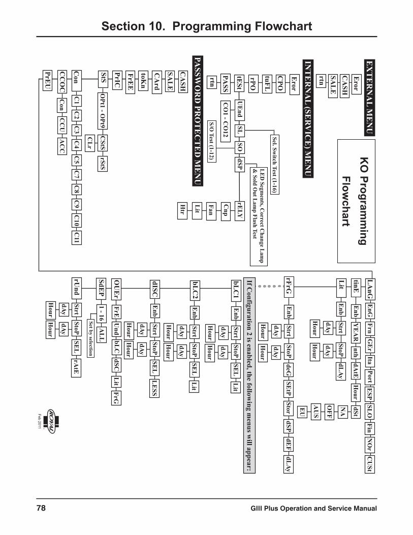
GIII Plus Operation and Service Manual78
Section 10. Programming FlowchartE
XT
ER
NA
L ME
NU
Eror
CA
SHSA
LE
rtn
INT
ER
NA
L (SER
VIC
E) M
EN
UE
ror
CPO
tuFL
PASSW
OR
D PR
OT
EC
TE
D M
EN
U
CA
SH
SAL
E
PrIC
StS
Con
CC
OC
PrEU
OPt1 - O
Pt9
CL
r
CStS
rStS
C1
C2
C3
C4
C5
C7
C8
C9
C10
Con
CC
UA
CC
LA
nG
tinE
Lit
rFrG
EnG
FrnG
Er
ItaPort
ESP
SLO
Enb
YE
AR
nthdA
tEH
ourdSt
NA
OFF
EU
AU
S
Enb
StrtStoP
SEtP
deGStor
dSP
dAy
Hour
dAy
Hour
If Configuration 2 is enabled, the follow
ing menus w
ill appear:
bLC
1
bLC
2
dISC
OU
Er
SdEP
rUnd
Enb
StrtStoP
dAy
Hour
dAy
Hour
SEL
Lit
Enb
StrtStoP
dAy
Hour
dAy
Hour
SEL
Lit
Enb
StrtStoP
dAy
Hour
dAy
Hour
SEL
LE
SS
FrEbL
CdSC
Lit
FrG
1 - 16A
LL
Set by selection
tESt
UE
ndSL
SOdSP
rELY
Sel. Switch Test (1-16)
LED Segm
ents, Correct C
hange Lamp
& Sold O
ut Lamp Flash Test
CO
1 - CO
12
S/O Test (1-12)
Cnp
Fan
Lit
Htr
PASS
rtn
KO
Programm
ingFlow
chart
StrtStoP
dAy
Hour
dAy
Hour
SEL
rAtE
Enb
StrtStoP
dAy
Hour
dAy
Hour
R
Feb 2011
Und
FinN
Or
CU
St
C11
dEF
FrEE
CA
rd
toKn
rPO
dLAy
dLAy

GIII Plus Operation and Service Manual 79
CREDIT AND REPLACEMENT POLICY Credits or replacements will be issued on warranty items if the proper procedures are followed:1. ROYAL VENDORS will pay shipping charges on all parts covered under this warranty when transportation has been made the most economical way. (Example: within the continental USA, regular
ground UPS). An A.R.S. (Authorized Return Service) sticker will be sent with all warranty parts. This method of shipping is preferred for returning parts to Royal.
2. Credits will only be issued to warranty parts that have been ordered in advance, not for parts ordered as stock. (NO EXCEPTIONS.)
3. When ordering warranty parts in advance, please have the full vender, refrigeration unit, and / or control board serial numbers.
4. A copy of the Packing Slip, the correct serial number and complete Return Material Tag (provided with part) are required for sending back parts. Please fill out the Return Material Tag completely, keeping the white copy for your records and sending the yellow tag back with the attached part. Make sure you have your company name, address, phone number, serial number, and model number, along with a brief explanation of the problem.
5. If the item returned is not under warranty, it will be sent back to you at your expense along with a US$10.00 handling fee or it will be scrapped.
6. All warranty parts should be properly wrapped and packed securely to avoid further damage. Parts that are returned from the field and have been tapped into, tampered with, not packaged properly or have had the serial plate or label removed, will void the warranty.
7. If parts are not returned within 15 working days, the invoice will be due in full.
Royal Vendors’ Publication 833099 Rev. 01cAugust 2014R Printed in the United States of America