rotor blade full-scale fatigue testing technology and researchturbine rotor blades. an advanced...
TRANSCRIPT
General rights Copyright and moral rights for the publications made accessible in the public portal are retained by the authors and/or other copyright owners and it is a condition of accessing publications that users recognise and abide by the legal requirements associated with these rights.
Users may download and print one copy of any publication from the public portal for the purpose of private study or research.
You may not further distribute the material or use it for any profit-making activity or commercial gain
You may freely distribute the URL identifying the publication in the public portal If you believe that this document breaches copyright please contact us providing details, and we will remove access to the work immediately and investigate your claim.
Downloaded from orbit.dtu.dk on: Mar 22, 2020
Rotor blade full-scale fatigue testing technology and research
Nielsen, Per Hørlyk; Berring, Peter; Pavese, Christian; Branner, Kim
Publication date:2013
Document VersionPublisher's PDF, also known as Version of record
Link back to DTU Orbit
Citation (APA):Nielsen, P. H., Berring, P., Pavese, C., & Branner, K. (2013). Rotor blade full-scale fatigue testing technologyand research. DTU Wind Energy. DTU Wind Energy E, No. 0041

Dep
artm
ent o
f W
ind
Ener
gy
E R
epor
t 201
3
Rotor blade full-scale fatigue testing technology and research
Per Hørlyk Nielsen, Peter Berring, Christian Pavese, Kim Branner
DTU Wind Energy E-0041
ISBN: 978-87-92896-71-1
December 2013

Authors: Per Hørlyk Nielsen, Peter Berring, Christian Pavese, Kim Branner
Title: Rotor blade full-scale fatigue testing technology and research
Department: Department of Wind Energy
ISBN: 978-87-92896-71-1 December 2013
Summary (max 2000 characters): Full scale fatigue test is an important part of the development and design of wind turbine blades. Testing is also needed for the approval of the blades in order for them to be used on large wind turbines. However, usually only one prototype blade is tested. Fatigue test of wind turbine blades was started in the beginning of the 1980´s and has been further developed since then. Structures in composite materials are generally difficult and time consuming to test for fatigue resistance. Therefore, several methods for testing of blades have been developed and exist today. These methods will be presented in this report giving the blade test facility operator a guide to choose the method that best fit the needs and economic constraints. The state of the art method is currently dual axis mass resonance, where the purpose of the test is to emulate the loads the blades encounter in operation.
Contract no.: 104.Kina.1.MFS.4-1-2-5
Project no.:
Sponsorship:
Sino-Danish Renewable Energy
Development (RED) Programme
Front page:
Pages: 28
Tables: 3
References: 18
Technical University of Denmark Department of Wind Energy Frederiksborgvej 399 Building 118 4000 Roskilde Denmark Phone 46775470 [email protected] www.vindenergi.dtu.dk


Rotor blade full-scale fatigue testing technology and research
Preface
This report is deliverable 1.1 of the project “Wind turbine rotor blade testing technology research and platform construction”. The project is supported by the Renewable Energy Development (RED) programme in which the Chinese and Danish governments are cooperating and aiming at institutional capacity building and technology innovation for renewable energy development. This particular project is a partnership between the Chinese Baoding Diangu Renewable Energy Testing and Research Co., Ltd., a national wind and solar energy key laboratory for simulation and certification and from Denmark the Department of Wind Energy, Technical University of Denmark, a Danish wind energy research department that has provided a major part of the wind energy research in Denmark and is one of the leading wind energy research institutions in the world. The project will focus on research for on-site, full-scale and down-scale structural testing of wind turbine rotor blades. An advanced blade on-site monitoring platform and full-scale testing platform will be constructed to strengthen the capacity of wind turbine blade testing and demonstrated in Baoding, city of Hebei Province in China. The project will provide the manufacturers with the possibility to do comprehensive blade testing in order to achieve test data for fulfilling requirements of standards and in order to obtain better and more optimized blade design. Meanwhile advanced experiment tool and valid test data can also be provided for the research and certification institutions in order to develop better design methods and certification guidelines and standards. The project has three main parts. The first part is research in full-scale and down-scale structural testing of wind turbine blades as well as condition monitoring for on-site testing of whole wind turbines. The next part is construction of platforms in China for full-scale fatigue testing of blades and on-site condition monitoring of wind turbines. Finally, the last part is to demonstrate the full-scale fatigue testing and the on-site condition monitoring. Roskilde, Denmark, December 2013
Rotor blade full-scale fatigue testing technology and research
Content
Summary ........................................................................................................................................ 6
1. Introduction .......................................................................................................................... 7 1.1 Purpose of blade testing .................................................................................................................... 7 1.2 Certification tests (static and cyclic) ................................................................................................... 7
2. Full scale fatigue techniques and equipment ....................................................................... 8 2.1 Short history on development of full scale test ................................................................................... 8 2.2 Regional differences for approval of blades ....................................................................................... 9 2.3 Full scale fatigue test used in relation to certification of blades .......................................................... 9 2.4 Full scale fatigue test used for research and development on blades .............................................. 10 2.5 Size related demands for full scale fatigue test ................................................................................ 11 2.6 Standards and guidelines for test of blades ..................................................................................... 12 2.7 Cost of equipment for different fatigue test techniques .................................................................... 12
3. Dual Axis Fatigue Testing ..................................................................................................13 3.1 Introduction ...................................................................................................................................... 13 3.2 Benefits and drawbacks of dual axis fatigue testing ......................................................................... 16 3.3 Requirements for equipment for dual axis fatigue testing ................................................................ 17 3.4 Requirements for load calculation on blades submitted to Dual Axis Fatigue Testing ..................... 20 3.5 Suppliers of equipment for fatigue test of blades ............................................................................. 24
4. Software for full scale test ..................................................................................................24 4.1 Demands and possibilities for software for full scale test ................................................................. 24 4.2 Suppliers of software for full scale test ............................................................................................. 25
References ...................................................................................................................................26
Acknowledgements ......................................................................................................................27

6 Rotor blade full-scale fatigue testing technology and research
Summary
Full scale fatigue test is an important part of the development and design of wind turbine blades. Testing is also needed for the approval of the blades in order for them to be used on large wind turbines. However, usually only one prototype blade is tested. Fatigue test of wind turbine blades was started in the beginning of the 1980´s and has been further developed since then. Structures in composite materials are generally difficult and time consuming to test for fatigue resistance. Therefore, several methods for testing of blades have been developed and exist today. These methods will be presented in this report giving the blade test facility operator a guide to choose the method that best fit the needs and economic constraints. The state of the art method is currently dual axis mass resonance, where the purpose of the test is to emulate the loads the blades encounter in operation.

Rotor blade full-scale fatigue testing technology and research 7
1. Introduction
Catastrophic failure of wind turbine blades, due to excessive loading or fatigue damage, can lead to the destruction of the entire machine. This can cause not only a significant economic loss, but also a risk for the safety of the surrounding areas. It is therefore important to ensure that the blades can endure the loading they are exposed to throughout their lifetime. In these respect full-scale tests is a vital tool. It is also important to subject the blades to loads which represent, as close as possible, the loading that these wind turbine components will encounter during their lifetime. 1.1 Purpose of blade testing Full scale testing is mandatory for certification of large wind turbine blades. The basic purpose of these blade tests is to demonstrate that the blade type has the prescribed reliability with reference to specific limit states with a reasonable level of certainty. According to Det Norske Veritas (DNV) [5], a limit state is a defined as a state beyond which the structure no longer satisfies the requirements. The following categories of limit states are of relevance for blade structures: ultimate limit state (ULS), fatigue limit state (FLS), and serviceability limit state (SLS). The blade should be manufactured according to a certain set of specifications in order to ensure that the test blade is representative of the whole series of blades. In other words, the purpose of the blade tests is to verify that the specified limit states are not reached and that the type of blade possesses the projected strength and lifetime. Normally, the full-scale tests used for certification are performed on a very limited number of samples; only one or two blades of a given design are tested so that no statistical distribution of production blade strength can be obtained. Therefore, although the tests do give information valid for the blade type, they cannot replace either a rigorous design process or the use of a quality control system for blade production. Additionally, tests can be used to determine blade properties in order to validate some vital design assumptions used as inputs for the design load calculations. Finally, full scale tests give valuable information to the designers on how the structure behaves in the test situation and which structural details that are important and should be included in the structural models for design. Especially, valuable information is obtained if the blade is tested to failure. 1.2 Certification tests (static and cyclic) According to DNV [5], it is required that the test program for a blade type shall be composed of at least the following tests in this order: • Mass, centre of gravity, stiffness distribution and natural frequencies • Static tests • Fatigue load tests • Post fatigue static tests All tests should be done in flapwise direction towards both the downwind (suction) and upwind (pressure) sides and in edgewise directions towards both the leading and trailing edges. If it is important for the design, also a torsion test is needed in order to determine the torsional stiff-

8 Rotor blade full-scale fatigue testing technology and research
ness distribution. The tests are undertaken to obtain two separate types of information. One set of information relates to the blade’s ability to resist the loads that the blade has been designed for. The second set of information relates to blade properties, strains and deflections arising from the applied loads. According to IEA standard 61400-23 [1], all tests in a given direction and in a given area of a blade shall be performed on the same blade part. The flap- and edgewise sequence of testing may be performed on two separate blades. However, if an area of the blade is critical due to the combination of flap- and edgewise loading, then the entire test sequence shall be performed on one blade.
2. Full scale fatigue techniques and equipment
Modern wind turbine blades are manufactured in FRP composite materials. The benefit of these material are the ease they can adapt to complex geometries and their ability to endure outdoor environments. The drawback is the lack of possibility to predict failure strength under both static and dynamic loading with high precision and reliability. Therefore is has been mandatory to test blades to achieve certification in order for them to be used on a wind turbine. 2.1 Short history on development of full scale test After the oil crisis in the 1970s, renewable energy became much more in focus and in particular wind turbines. In Denmark several small companies started to produce wind turbines from 5 – 22 kW. The material for the blades of these turbines were most often wood and/or fiberglass. Larger wind turbines were built in USA and Germany with blades in steel or aluminium, but unfortunately these larger blades suffered from fatigue. At that time there did not exists equipment to fatigue test these large blades. The blades for the smaller wind turbines were improved by trial and error regarding fatigue resistance. The first tests of wind turbine blades were static tests. These tests were made in simple manner with cranes or sand bags. In the 1980s the Danish authorities increased the demand for documentation before a wind turbine could be erected, and soon the development for a test method for fatigue resistance was started and in the beginning of the 1980´s RISØ National Laboratory in Denmark started to test blade with a method that uses resonance excitation to apply damage cycles to the blade in a single direction. Other research facilities in the Netherlands and USA followed. Much later dual axis fatigue tests were introduced to obtain a more realistic loading on the blade.

Rotor blade full-scale fatigue testing technology and research 9
Test facility Country Supplier Equipment types Test direction WMC Netherlands In house
construction Forced deflection – hydraulic
Dual axis
Blaest Denmark In house construction
Rotating mass-electric
Single axis
NREL USA In house construction developed with MTS
Forced deflection – hydraulic
Dual axis
Oscillating mass - hydraulic
Dual axis
CENER Spain MTS Oscillating mass - hydraulic
Dual axis
Frauenhofer Germany In house construction
Forced deflection – hydraulic
Dual axis
Narec United Kingdom
In house construction
Forced deflection – hydraulic
Dual axis
SGS China MTS Oscillating mass - hydraulic
Dual axis
Table 1: Large blade test facilities. See Figure 1 and 2 for an example of fatigue test with single axis mass resonance using rotating mass test. 2.2 Regional differences for approval of blades The approval of wind turbine blades varies from country to country. Most authorities demand a static test for wind turbines with a swept area larger than 1 m2. And for turbines with a swept area larger than 40 m2 the blades has to be certified by a classification body. This is describes in IEC 61400-2 [2]. However this does not mean that the blades have to be subjected to a fatigue test. If the approval of the wind turbine is regulated by IEC 61400-22 [3] or the certification is done by Det Norske Veritas the fatigue test is mandatory. In Europe, Denmark is the only country demanding a fatigue test of blades with a swept area larger than 40 m2. 2.3 Full scale fatigue test used in relation to certification of blades From authorities and classification societies there has been varying demands for fatigue test of blades. As an example GL has no demand for a fatigues test. The number of measurement sensors used in fatigue tests is in general fewer than for the accompanying static test. For fatigue test the measurements are often limited to a small number of strain gauges and the use of thermography equipment. Instead of measurements the blade is surveyed at frequent intervals with a visual inspection to detect damages. For the certification of blades time schedule is very important and therefore accelerated tests is often used. This means that the number of load cycles is reduced and the equivalent load is raised. For complicated composite structures such as wind turbine blades this is often questioned because of the uncertainty related with the S/N curve approach and since the Palmgren-Miners rule is highly questionable for composite materials and structures. Another possibility used is to remove the tip of the blade

10 Rotor blade full-scale fatigue testing technology and research
and thereby obtain a higher eigenfrequency. If part of the blade is removed it is necessary to design these parts with higher safety factors in order to compensate for the lack of test.
Figure 1: Fatigue test with single axis mass resonance using rotating mass test (courtesy of Blaest).
Figure 2: Flapwise fatigue test (courtesy of Blaest) 2.4 Full scale fatigue test used for research and development on blades The focus of fatigue test in research and development is often on the discrepancies of the defect discovered on wind turbines during operation and defect found in full scale test of a

Rotor blade full-scale fatigue testing technology and research 11
prototype blade. Researches also focus on other aspects related to differences between the testing situation and the real operation situation. Some of these focus areas listed without priority are: • Difference in manufacturing or material quality between prototype test blade and blade from
series production. • Load calculation does not cover the actual conditions for the turbine (turbulence, stand-still
vibrations etc.). • S/N curves and accumulated damage assumption (Palmgren-Miner, rainflow counting etc.)
is not accurate. • Test method does not emulate the condition which is assumed in the aeroelastic models
used to calculate the fatigue loads. In composites, fracture mechanic properties are very difficult to measure or calculate exact.A numeric model with reliable crack growth prediction for a complete blade is generally not possible due to computational time. Therefore, analytical and numerical modelling is very difficult and the prediction of the fatigue strength is subjected to large uncertainty. Fatigue tests performed until failure in order to investigate the failure strength are very rare, but are an essential tool to understand the fatigue mechanisms and improve the structural analysis of blades. 2.5 Size related demands for full scale fatigue test Apart from the demands (size of the test facility) that follows the size and higher loads associated with test of ever larger blades, other issues are also important to consider. The aerodynamic resistance caused by blade motion in flapwise or combined flapwise and edgewise direction can affect the deflection of the blade and make controlling the loads difficult. It also increases the power consumption for the test. This can be remedied by aerodynamic parts fastened to the blade which then reduce the aerodynamic damping.
Figure 3: Aerodynamic attachment for lowering the energy consumption. Large blades also have low eigenfrequency and this result in test schedules with very long time spans. If the tip part is removed it is possible to obtain higher eigenfrequency. This will of course mean that the removed part of the blade is not tested. Low eigenfrequency means longer testing time. For very large blades the edgewise load become is in the same order at the

12 Rotor blade full-scale fatigue testing technology and research
flapwise load. For most blades the most solid part is the thick load carrying laminates which is positioned approx. 1/3 from the leading edge. The leading and trailing edge of the blades are usually very thin shell made with sandwich construction and is poorly suited to carry a point load from the saddle for the fatigue loading equipment. For blades of multi MW turbines, the relative thickness of the aerodynamic shell compared to the other parts of the blade is smaller and as the edgewise loads increases it can require a local reinforcement of the blade to transfer the loading from the equipment. 2.6 Standards and guidelines for test of blades Standards for test of blades are issued by international standardisation organisations, national authorities and classification societies. For wind turbines with a swept area larger than 200 m2 national authorities requires the approval of the turbine and its components from a classification society. The IEC standard incorporates rules for fatigue test. The rules specify conditions for the test, documentation, the derivation of the loads and among others safety factors used to correct for the uncertainty in accelerated test. The class rules from Germanischer Lloyd [4] do not have any demand for full scale fatigue test, but rely on numerical structural analysis, coupled with static full scale tests. The class rules DNV-DS-J102 [5] from Det Norske Veritas specify fatigue testing of the blade and have references to IEC 61400-23 [1] regarding test loads and reporting. 2.7 Cost of equipment for different fatigue test techniques It is generally not possible to get information for the purchase cost for the equipment used for the different fatigue test methods. The reason is that the equipment is produced in very small numbers and that the cost is dependent on the customer and often the equipment is special made for the customer. Regional differences in cost can also be expected. Generally, cost of fatigue test equipment must be obtained by getting an offer directly from a equipment supplier based on a specific request. In the following is a rough cost estimate for different fatigue test methods given based on engineering judgement.

Rotor blade full-scale fatigue testing technology and research 13
Electrical Actuated
Hydraulic Actuated
Control system
Multiple actuators
Single axis mass resonance – Rotating mass
30 40 20 NA
Single axis mass resonance – Linear travel
NA5) 60 30 NA
Single axis resonance ground1) based
NA2) 75 10 NA
Dual axis mass resonance - Linear travel
NA5) 100 100 100
Dual axis mass resonance – Rotating mass
NA3) NA3) NA3) NA3)
Dual axis resonance ground based
NA3) 1203) 30 120
Table 2: Rough cost estimate of fatigue test methods. Dual axis mass resonance - linear travel has index 100. A complete system for blades up to 45 m is estimated to cost 1.2 mill €. Data acquisition and measurement systems are estimated at 150,000 €.
NA – Not applicable 1) In ground bases systems the load equipment has one or more anchor points on the ground. 2) Ground bases systems with electric driven actuation are known for small blades. There does not
exist examples of systems for larger blades. This does not mean that electric driven actuation is not feasible, but no systems have been developed so far.
3) No system with rotating masses is published or known. This might be due to the mass exciting the blade in other direction than intended, and thereby challenge the control system.
4) Ground based actuation is indexed higher because of the installation of anchoring points in the facility
5) Systems in this configuration are not published or known.
3. Dual Axis Fatigue Testing
3.1 Introduction The general issues related to fatigue testing have already been discussed in the previous sections. It has also been mentioned how tests usually are performed in the flapwise (wind excited) and edgewise (gravity excited) directions separately (“single axis fatigue test”). It is important to remark that in-service loads have components in both directions at the same time. In order to fulfil the requirement of applying loads, during the certification process, as close as possible to the ones encounter during the operation period, it is necessary to investigate a method which allows applying the loading in different directions simultaneously.

14 Rotor blade full-scale fatigue testing technology and research
To overcome the usual practice of performing single axis fatigue testing, multi-axial loading can be used, so that the flapwise and edgewise tests are performed at the same time. This method is called dual axis fatigue testing. These tests can be performed in several ways but only two approaches have been widely adopted. The first method to be developed was the forced displacement testing method [6], which is performed using hydraulic cylinders attached to a fixed structure to cycle the blade back and forth. Its main advantage is a precise control of the phase angle between the flapwise and edgewise loads, but the expensive hydraulic systems needed to provide the required forces and tip displacements for large wind turbine blades, makes this approach very impractical. Another disadvantage of this test technique is that it is usually only practical to adopt a single-point loading for each axis, which achieves only a linear bending moment distribution.
Figure 4: NREL's Dual Axis Force Displacement fatigue test [7]. Figure 4 shows an example of dual axis force displacement fatigue testing equipment developed by NREL [7]. The forced displacement fatigue tests commonly performed on wind turbine blades have the following characteristics [6][7][8]: • Excitation frequency is much lower than natural frequency (a quasi-static system) • Actuator force and blade displacement are in-phase • Actuator force and displacement directly correlate with bending moments • Actuator displacement is dictated by blade deflections (longer actuators for larger blades) • Inertia loads are small compared to applied loads The second and most popular approach to dual axis fatigue testing is the resonant method, which involves using a mass that is mounted on the blade to excite it at its resonant frequency. The mass can be moved by hydraulic cylinders or a rotating eccentric mass can be used, often powered by an electric motor. The response of the blade can be tuned modifying the amplitude of the oscillations of the mass in case a hydraulic system is used, or varying the excitation

Rotor blade full-scale fatigue testing technology and research 15
frequency away or towards the blade resonant frequency if the rotating eccentric mass is used. The advantages of this testing method are [9]: • On large wind turbine blades, it requires less energy than the hydraulic systems used for
the force displacement technique • It is more compact and substantially cheaper than the force displacement • The bending moment distribution can be tuned by adding static masses to the blade to
adjust its mode shape • The bending moment distribution can be scaled for larger blades The British National Renewable Energy Centre (Narec) has implemented dual axis fatigue testing of blades by exciting the first flapwise and the first edgewise mode of the blade simultaneously [10]. The system developed has the following characteristics (Figure 5): • Resonant mass system – compact design (Compact Resonant Mass) • Hydraulic actuator • Reduced energy use compared to forced displacement • Flexible hoses • 24hr non-stop fatigue testing offered • Automatic shut-down:
a) Mass displacement b) Acceleration c) Tip displacement d) Strain
.. Figure 5: Narec's CRM Dual Axis Fatigue equipment [10].

16 Rotor blade full-scale fatigue testing technology and research
A hybrid resonant/force displacement dual axis test method was developed by NREL [8]: the flapwise load is actuated using the resonance procedure, while in the edgewise direction a dis-placement is forced using a hydraulic cylinder driving a bell crank (Figure 6).
Figure 6: NREL's B-REX test System [8]. This procedure allows a precise implementation of a control strategy for the phase angle between the two loads, although it is difficult to perform a scaling for large wind turbine blade. Moreover, the edgewise bending distribution can only be linear. In the next paragraph, it is discussed whether or not the dual axis testing, in particular the most promising resonant excitation method, represents an improvement over single axis testing. In particular in the light that dual axis fatigue testing is being more representative of the loading seen in service and allowing a potential reduction in the weight of wind turbine blades and in the duration of fatigue tests. 3.2 Benefits and drawbacks of dual axis fatigue testing The main reason that leads to the development of the dual axis fatigue testing technique was the need to provide fatigue blade testing with a load configuration as close as possible to the real loading which the blade is subject during its lifetime. If the requirements are fulfilled, this approach is shown to be more representative of the loading seen in service and can thus provide a substantial benefit to the fatigue analysis compared to the single axis fatigue testing [7]. As already described in the previous section, service loads occur simultaneously both edgewise and flapwise, making it necessary to develop a procedure able to apply loads in two directions. One of the limitations of the single axis testing is that the flap and edge phase angle must be zero. According to [7], on operating wind turbines, the edge loading tends to have a more severe reversing component, and the peaks of the flap and the edge operating load components are separated by a statistically varying but non-zero phase angle, with both peaks rarely occurring at the same time. The single axis limitations are then simplifications of the two-axis capabilities and the true operating environment, which increase the uncertainty of the blade test results. Further analysis has been performed on simulated load-time histories to obtain the distribution of the phase angle between the flapwise and the edgewise loads [11] showing that applying a

Rotor blade full-scale fatigue testing technology and research 17
dual axis testing procedure is beneficial to represent the real service loads acting on a wind turbine blade compared to single axis method. Dual axis fatigue testing also takes into consideration the coupling between flap and edge modes, detecting the association between the loads in the two directions. This dependence is important because it has the result that strain patterns will arise from operation loads which are not thoroughly investigated by single axis testing [12]. Moreover, the interactions between the edgewise and flapwise bending moments in service can result in the blade being damaged in areas that are not properly tested by conventional, single axis fatigue testing. If the load levels are correct for both axes at a given point on the blade then dual axis fatigue testing represents a considerable improvement over single axis testing. However, because any attempt to optimise the flapwise bending moment distribution also affects the edgewise moment distribution, it is harder to configure correctly a dual axis test that matches the target loads along the full blade length [9]. This is one of the main disadvantages to perform dual axis fatigue testing: the difficulty to match within a certain accuracy range the bending moment distribution on both flapwise and edgewise directions. This difficulty increases using a mass resonant system, which requires a more complex procedure to control and tune the frequencies and the size of the masses deployed on the blade. This mass-frequency tuning is usually done by a trial and error process, but it is possible to find in literature description of optimization methods that allows the load distribution to be tuned for both axes simultaneously [9]. The forced displacement method allows a better control on the force applied to the blade, since it is fairly easy to tune the actuators to the target bending distribution. The more loading points and actuators applied on the blade the better the accuracy. Another clear and important advantage of the dual axis is related to testing time. It is shown in [9], that the simulated required testing time is reduced to 60% of the time that is required to perform the equivalent sequential single axis tests for a blade of the 2-MW turbine demonstration model included in GHBLADED [13]. 3.3 Requirements for equipment for dual axis fatigue testing As already reported in the introduction, there are substantial economic and practical differences between the forced displacement, the mass resonant and the hybrid methods. The forced dis-placement equipment is extremely expensive and energy consuming for large blades, since it uses hydraulic actuators which have to be scaled according to the dimension of the blade and the force that has to be applied during the testing. The mass resonant system is very compact and cheaper comparing to the forced displacement one, but the higher complexity of the procedure requires software able to implement and monitor difficult control strategies. The hybrid system is a good compromise between the two methods: it offers an easier control setup with the presence of a forced displacement actuator, which has a lower cost compared to the actuators that have to apply a load in two directions. In the following section, a brief survey of the equipment for dual axis fatigue testing available on the market is presented. 3.3.1 Forced displacement method Pure forced displacement equipment is highly unpractical and expensive and no information can be found regarding commercial products able to perform dual axis fatigue testing.

18 Rotor blade full-scale fatigue testing technology and research
3.3.2 Mass resonant system The only company providing a commercial system for dual axis fatigue testing using the mass resonant system is MTS. The product is called Inertial Resonance Excitation (IREX) System and it can be used for both single and dual axis fatigue testing. For the second configuration, it is possible to install a setup that combines multiple IREX systems to enable both flapwise and edgewise testing simultaneously [14]. The system has the specification reported in Table 3. STANDARD SPECIFICATIONS
Force capacity 50 kN
Moving mass range 160-1010 kg
Moving mass increment 50 kg
Stationary mass (typ) 170-230 kg
Total mass (typ) 330-390 kg
Dimensions 1.42x.53x.48 m
Stroke 0.15 m
Velocity 1.37 m/sec
Servovalve 120 lpm
Hose sizes -16P, -16R, -8D JIC
SPECIAL OPTIONS
Tilt angle range +/- 10 deg
Tilt angle increment 2 DEG
Accumulation required 2 L (normal)
Table 3: IREX Standard Specifications and Special Options [14].

Rotor blade full-scale fatigue testing technology and research 19
Figure 7: MTS's IREX System installation scheme According to [14], MTS provides also blade resonant fatigue test control software to tune each IREX device as a single channel. The linear motion control includes adjustable amplitude and frequency, and advanced dual mode control allows programming of blade acceleration, displacement or strain. 3.3.3 Hybrid systems Most of the existing hybrid systems installed and tested in operating test facilities are made in-house. In [15], an estimation of the requirements for equipment for a hybrid dual axis fatigue testing is made, along with a preliminary capital cost estimate for such system, which is again not available as a commercial product. To realize this dual axis testing system, some of the components are made in-house and some are bought by MTS (hydraulic actuators, installation supports, etc.). In general, the installation of a hybrid system is complex and it depends on many factors related to the space available in the facilities, to the dimensions of the blades to be tested and the budget provided by the customer. While it is easy to adapt a mass resonant equipment to the different demands of the buyer, providing a standard product that can be used for different applications, same thing cannot be done for the hybrid system: the forced displacement part of the equipment needs to be custom-made to match the practical characteristics of the facility. MTS provides a commercial product that can be used to perform hybrid fatigue testing. This commercial solution consists in combining the I-REX system previously described with a system called G-REX, showed in Figure 8.

20 Rotor blade full-scale fatigue testing technology and research
Figure 8: MTS's G-REX system 3.4 Requirements for load calculation on blades submitted to Dual Axis
Fatigue Testing The calculation of the loads to apply to blades submitted to dual axis fatigue testing is one of the most critical features for these testing methods. In general, the analysis procedure for the load calculation of fatigue test cases follows the steps reported below [9]. 1. Wind turbine simulation software is used to obtain the service life loads at a certain number
of stations (or nodes or blade sections) along the blade length for the load cases defined in the design standards.
2. A strain analysis is performed at all the stations along the blade for each load case. By investigating strain instead of stress, it is possible to perform the analysis without knowledge of the blade composite layup. A strain-time history at the i-th node can be generated from the flap and edge bending moment time histories (step 1) using equation (1). (1)
In [9], only the axial strain along the blade caused by bending is evaluated in detail as there are few fatigue data available for shear and combined stresses.
3. Fatigue analysis is performed at each blade cross section, using the strain time histories. These are rainflow counted [16] to allow the variable amplitude load-time history to be
Rotor blade full-scale fatigue testing technology and research 21
analysed as a series of constant amplitude cycles, defined by their range, mean and frequency of occurrence. Once this is done, the well-known Palmgren-Miner rule can be applied [17][18] to evaluate the total damage D, occurring for each load case (equation (2)). (2)
Where i are the loading level for a certain load case, ni is the number of cycles occurring for that load level and Ni is the number of cycles that it would take to fail the material at that load level.
4. Since it is obviously not practical to perform a fatigue test with the time span of a wind turbine blade (e.g. 20 years), the number of cycles for the test must be decreased and an equivalent higher loading scheme must be found. In other words, the flapwise and edgewise equivalent bending moment, that causes the same amount of damage as the service life on the edgewise and flapwise neutral axes, are calculated for each blade section and for a selected and feasible number of cycles (so the test can last weeks and not years).
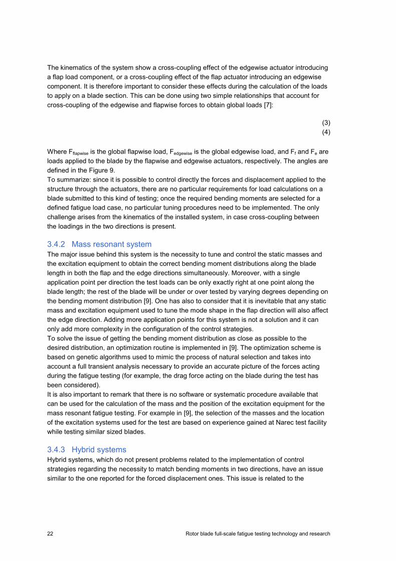
This is the basic scheme for requirements for load calculation in both single axis and dual axis fatigue testing. However, using the procedure to implement a dual axis fatigue testing scheme, can cause problems. A brief description of these issues behind the methodologies used for loads estimation is reported below for each type of system. 3.4.1 Forced displacement method As already described in the first part of this section, actuator force and displacement are directly correlated with the bending moments required by the selected testing session. Once the fatigue load case to implement is defined and the equivalent loading scheme is found, the implementation of the loads to apply for the dual axis method is straight forward, since the forced displacement system allows direct control on the bending moments applied. To eventually increase the accuracy of these bending moments, more load application points need to be implemented. One of the challenges regarding the implementation of the correct loads for this method is related to the correct execution of the amplitudes of the flapwise and the edgewise loading. It is possible to take as example the forced displacement system installed in NREL and analysed by [7], and described in Figure 9.
Figure 9: NREL's Forced Displacement System hardware schematic (left) and kinematics (right)
22 Rotor blade full-scale fatigue testing technology and research
The kinematics of the system show a cross-coupling effect of the edgewise actuator introducing a flap load component, or a cross-coupling effect of the flap actuator introducing an edgewise component. It is therefore important to consider these effects during the calculation of the loads to apply on a blade section. This can be done using two simple relationships that account for cross-coupling of the edgewise and flapwise forces to obtain global loads [7]:
(3) (4)
Where Fflapwise is the global flapwise load, Fedgewise is the global edgewise load, and Ff and Fe are loads applied to the blade by the flapwise and edgewise actuators, respectively. The angles are defined in the Figure 9. To summarize: since it is possible to control directly the forces and displacement applied to the structure through the actuators, there are no particular requirements for load calculations on a blade submitted to this kind of testing; once the required bending moments are selected for a defined fatigue load case, no particular tuning procedures need to be implemented. The only challenge arises from the kinematics of the installed system, in case cross-coupling between the loadings in the two directions is present. 3.4.2 Mass resonant system The major issue behind this system is the necessity to tune and control the static masses and the excitation equipment to obtain the correct bending moment distributions along the blade length in both the flap and the edge directions simultaneously. Moreover, with a single application point per direction the test loads can be only exactly right at one point along the blade length; the rest of the blade will be under or over tested by varying degrees depending on the bending moment distribution [9]. One has also to consider that it is inevitable that any static mass and excitation equipment used to tune the mode shape in the flap direction will also affect the edge direction. Adding more application points for this system is not a solution and it can only add more complexity in the configuration of the control strategies. To solve the issue of getting the bending moment distribution as close as possible to the desired distribution, an optimization routine is implemented in [9]. The optimization scheme is based on genetic algorithms used to mimic the process of natural selection and takes into account a full transient analysis necessary to provide an accurate picture of the forces acting during the fatigue testing (for example, the drag force acting on the blade during the test has been considered). It is also important to remark that there is no software or systematic procedure available that can be used for the calculation of the mass and the position of the excitation equipment for the mass resonant fatigue testing. For example in [9], the selection of the masses and the location of the excitation systems used for the test are based on experience gained at Narec test facility while testing similar sized blades. 3.4.3 Hybrid systems Hybrid systems, which do not present problems related to the implementation of control strategies regarding the necessity to match bending moments in two directions, have an issue similar to the one reported for the forced displacement ones. This issue is related to the

Rotor blade full-scale fatigue testing technology and research 23
kinematic interactions of the forced displacement part of the system with the forces acting on the blade during the fatigue test. For example, one can consider the B-REX system developed by NREL and showed in Figure 10.
Figure 10: NREL's Hybrid System B-REX [8]. The pushrod introduces forces in both the flap and lead-lag directions whenever the pushrod is acting non-orthogonal to the blade flap motion. As the blade moves in the flap direction, the pushrod angle moves through a range of small angles that induce small but significant flap forces [8]. This behaviour is shown in Figure 11which describes the kinematics of the system.
Figure 11: Pushrod/bell-crank kinematic model [8].

24 Rotor blade full-scale fatigue testing technology and research
The solution is to choose a configuration of the pushrod which minimizes its force in the flapwise direction for a force in the edgewise direction able to match the required edge bending moment distribution. In [8], the correct configuration is chosen as the one that minimizes equation (5).
(5)
where Ff is the flap force, Fe the edge force, xe the edge blade position, yf the flap blade position, L the pushrod length and R the bell-crank radius. In conclusion, as for the forced displacement systems, also the hybrid systems need a careful study concerning the load application points and the forces acting on the system during the fatigue testing. 3.5 Suppliers of equipment for fatigue test of blades Equipment for full scale tests of wind turbines is often manufactured by local suppliers in cooperation with the test centre. The local supplier has often experience in machining and hydraulics. The control of the equipment is often supplies by a second supplier as the control demands specific experiences. The demand for test equipment within a region such as Europe is limited and often the specification varies from test centre to test centre in a such a way that demands dedicated equipment. One supplier that does have a product group is MTS in Minnesota, which supplies equipment worldwide. MTS have products for both single axis and dual axis testing. Both system rely on hydraulic driven oscillating mass with is mounted on the blade on a saddle. For dual axis tests two saddle with masses are used with one operating in the flap wise direction and the other operating in the edgewise (lead lag) direction.
4. Software for full scale test
4.1 Demands and possibilities for software for full scale test In relation to fatigue test, software is important in relation to the preparation of the test and execution of the test. Additionally, software is often used to control the parameters of measurement amplifiers and to log measurements. In the preparation of the test, the position of the load equipment and additional masses has to be calculated in order to obtain the desired distribution of the bending moment and thereby the accumulated damage along the length of the blade. During the test software is used to control the load equipment and survey the loading of the blade. For dual axis testing the excitation of the desired mode shaped can be very difficult as the low order flapwise and edgewise frequencies usually do not coincide. A separate system is required for the safety of the test. This is often coupled to separate sensors witch are activated when the deflection of the blade reach predetermined limits. This information is transmitted to

Rotor blade full-scale fatigue testing technology and research 25
the control system, but if the control system is not able to reduce the deflection of the blade immediately the safety system stops the test before the blade is (further) damaged. Although, it could be an advantage that the software for the control of the loading equipment and the data acquisition for the measurements are coupled, so that there is only one interface for the operator, this is not necessary. This advantage is because control algorithm uses a feedback of displacement measurement to operate the loading equipment. The synchronisation of the control parameters and the other measurement such as displacement and strains can be valuable in the interpretation of the test results. 4.2 Suppliers of software for full scale test Software for full scale testing is often developed in conjunction with the development of the hardware part of the test equipment i.e. oscillation or rotating masses and hydraulic actuators. This is particular true regarding the control algorithm and safety measures. This means that a large part of the test centre used a system developed in house. A major supplier of software for fatigue test equipment is MTS.

26 Rotor blade full-scale fatigue testing technology and research
References
[1] IEC Standard 61400-23 rev L (2011): Full-scale structural testing of rotor blades, International Electrotechnical Commission
[2] IEC Standard 61400-2 (2006): Design requirements, International Electrotechnical Commission
[3] IEC Standard 61400-22 (2010): Conformity testing and certification, International Electrotechnical Commission.
[4] GL Renewables Certification (2012): Guideline for the Certification of Offshore Wind, Turbines Germanischer Lloyd Industrial Services GmbH
[5] Det Norske Veritas (2010): DNV-DS-J102 Design and Manufacture of Wind Turbine Blades, Offshore and Onshore Wind Turbines, Det Norske Veritas
[6] Van Delft and Van Leeweun (1994): Full-scale testing of wind turbine rotor blades, EWEC Greece
[7] Hughes, S., Musia,l W., and Stensland, T. (1999): Implementation Of A Two-Axis Servo-Hydraulic System For Full-Scale Fatigue Testing Of Wind Turbine Blades, National Renewable Energy Laboratory USA.
[8] White, D., Musial, W. and Engberg, S. (2005): Evaluation of the New B-REX Fatigue Testing System for Multi-Megawatt Wind Turbine Blades, 43rd AIAA Aerospace Sciences USA.
[9] Greaves, P.R., Dominy, R.G., Ingram, G.L., Long, H., and Court, R. (2012): Evaluation of dual-axis fatigue testing of large wind turbine blades, Journal of Mechanical Engineering Science.
[10] Court, R. (2012) Developments in Test Facilities for the Wind Industry. [11] White, D.L. and Musial, W.D.( 2003) : The effect of load phase angle on wind turbine blade
fatigue damage, National Renewable Energy Laboratory USA. [12] Court, R.S., Ridley, S., Jones, H., Bonnet, P.A. and Dutton, A.G. (2009): Fatigue testing of
wind turbine blades with computational verification, ICCM-17 Edinburgh. [13] GL, Garrad Hassan (2013): Bladed Software. [14] MTS. (2012). Wind Turbine Testing Solutions. USA [15] Malhotra P., Hyers R.W., Manwell J.F. and McGowan J.G. (2011). A review and design
study of blade testing systems for utility-scale wind turbines. Renewable and Sustainable Energe Reviews, 16, 284-292.
[16] Downing S.D. and Socie D.F. (1982). Simple rainflow counting algorithms. Int J Fatigue, 4, 31-40
[17] Miner M.A. (1945). Cumulative damage in fatigue. J Appl Mech, 12, A64-A159 [18] Palmgren A. (1924). Die Lebensdauer von Kugellagern. VDI - Zeitschr, 1924, 339-341

Rotor blade full-scale fatigue testing technology and research 27
Acknowledgements
This work is supported by a grant of the Sino-Danish Renewable Energy Development (RED) Programme Component 2. The supported RED-project is titled “Wind Turbine Rotor Blade Testing Technology Research and Platform Construction” and is entered by and between the Royal Danish Embassy in Beijing, Baoding Diangu Renewable Energy Testing and Research Co. Ltd. and DTU Wind Energy. Danida file reference number is 104.Kina.1.MFS.4-1-2-5. The support is gratefully acknowledged.

DTU Wind Energy is a department of the Technical University of Denmark with a unique integration of research, education, innovation and public/private sector consulting in the field of wind energy. Our activities develop new opportunities and technology for the global and Danish exploitation of wind energy. Research focuses on key technical-scientific fields, which are central for the development, innovation and use of wind energy and provides the basis for advanced education at the education. We have more than 240 staff members of which approximately 60 are PhD students. Research is conducted within nine research programmes organized into three main topics: Wind energy systems, Wind turbine technology and Basics for wind energy.
Technical University of Denmark Department of Wind Energy Frederiksborgvej 399 Building 118 4000 Roskilde Denmark Phone 46 77 50 85 [email protected] www.vindenergi.dtu.dk