rotary coded switches (smd) - nidec copal electronics · sh-7000 rotary coded switches (smd) no. of...
TRANSCRIPT
※ Please refer to the LIST OF PART NUMBERS when placing orders.
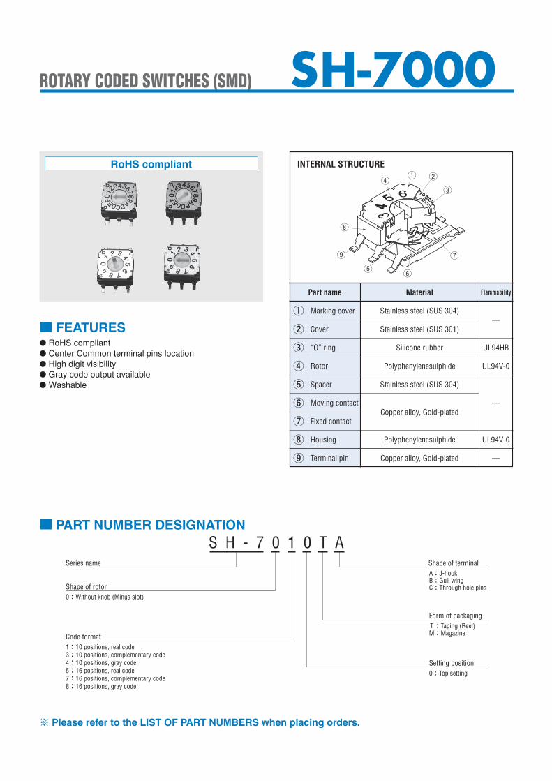
● RoHS compliant● Center Common terminal pins location ● High digit visibility● Gray code output available● Washable
■ FEATURES
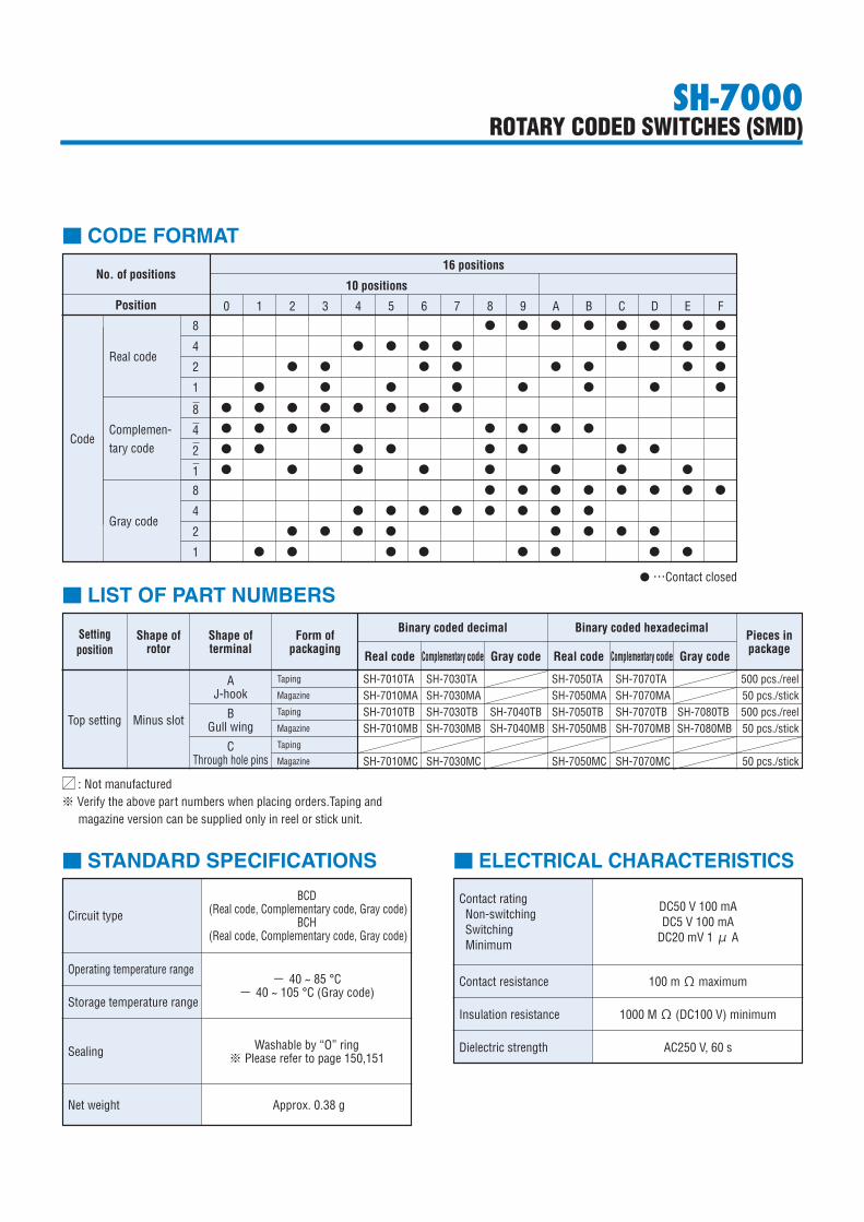
INTERNAL STRUCTURE
Part name
②
③
④
⑤
⑥
⑦
⑧
⑨
“O” ring
Cover
Rotor
Spacer
Moving contact
Fixed contact
Housing
Terminal pin
Material Flammability
UL94HB
UL94V-0
—
UL94V-0
—
Silicone rubber
① Marking cover—
Stainless steel (SUS 304)
Stainless steel (SUS 301)
Polyphenylenesulphide
Stainless steel (SUS 304)
Copper alloy, Gold-plated
Polyphenylenesulphide
Copper alloy, Gold-plated
■ PART NUMBER DESIGNATIONS H - 7 0 1 0 T A
Series name
Shape of rotor0:Without knob (Minus slot)
Code format1:10 positions, real code3:10 positions, complementary code4:10 positions, gray code5:16 positions, real code7:16 positions, complementary code8:16 positions, gray code
Shape of terminalA:J-hookB:Gull wingC:Through hole pins
Form of packaging T:Taping (Reel)M:Magazine
Setting position0:Top setting
SH-7000
①④ ②③
⑦
⑥⑤⑨
⑧
ROTARY CODED SWITCHES (SMD)
RoHS compliant
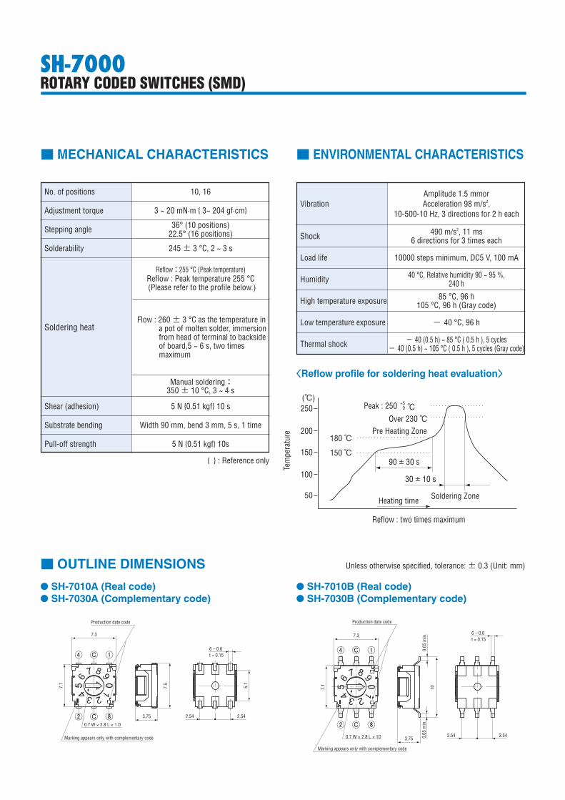
10 positions
■ CODE FORMAT
No. of positions16 positions
Position 0 1 2 3 4 5 6 7 8 9 A B C D E F
● ● ● ● ● ● ● ●
● ● ● ● ● ● ● ●
● ● ● ● ● ● ● ●
● ● ● ● ● ● ● ●
● ● ● ● ● ● ● ●
● ● ● ● ● ● ● ●
● ● ● ● ● ● ● ●
● ● ● ● ● ● ● ●
● ● ● ● ● ● ● ●
● ● ● ● ● ● ● ●
● ● ● ● ● ● ● ●
● ● ● ● ● ● ● ●
Code
Real code
8
4
2
1
8
4
2
1
8
4
2
1
Complemen-tary code
Gray code
● …Contact closed
■ LIST OF PART NUMBERS
Setting position
Shape of rotor
Top setting
Shape of terminal
AJ-hook
Minus slot BGull wing
CThrough hole pins
Form of packaging
Taping
Magazine
Taping
Magazine
Taping
Magazine
Binary coded decimal
Complementary code Gray codeReal code Complementary code Gray codeReal code
Binary coded hexadecimal
SH-7010TA SH-7030TA SH-7050TA SH-7070TA 500 pcs./reelSH-7010MA SH-7030MA SH-7050MA SH-7070MA 50 pcs./stickSH-7010TB SH-7030TB SH-7040TB SH-7050TB SH-7070TB SH-7080TB 500 pcs./reelSH-7010MB SH-7030MB SH-7040MB SH-7050MB SH-7070MB SH-7080MB 50 pcs./stick
SH-7010MC SH-7030MC SH-7050MC SH-7070MC 50 pcs./stick
Pieces in package
: Not manufactured※ Verify the above part numbers when placing orders.Taping and
magazine version can be supplied only in reel or stick unit.
■ STANDARD SPECIFICATIONS
Circuit type
Operating temperature range
Storage temperature range
Sealing
Net weight
BCD (Real code, Complementary code, Gray code)
BCH (Real code, Complementary code, Gray code)
− 40 ~ 85 °C− 40 ~ 105 °C (Gray code)
Washable by “O” ring※ Please refer to page 150,151
Approx. 0.38 g
Contact ratingNon-switchingSwitchingMinimum
Contact resistance
Insulation resistance
Dielectric strength
DC50 V 100 mADC5 V 100 mA
DC20 mV 1 μ A
1000 MΩ (DC100 V) minimum
100 mΩ maximum
AC250 V, 60 s
■ ELECTRICAL CHARACTERISTICS
SH-7000ROTARY CODED SWITCHES (SMD)
A:J-hookB:Gull wingC:Through hole pins
Form of packaging T:Taping (Reel)M:Magazine
Setting position
SH-7000ROTARY CODED SWITCHES (SMD)
No. of positions
Adjustment torque
Stepping angle
Solderability
Shear (adhesion)
Substrate bending
Pull-off strength
10, 16
3 ~ 20 mN·m { 3~ 204 gf·cm}
36° (10 positions)22.5° (16 positions)
245 ± 3 °C, 2 ~ 3 s
5 N {0.51 kgf} 10 s
Manual soldering:350 ± 10 °C, 3 ~ 4 s
Width 90 mm, bend 3 mm, 5 s, 1 time
5 N {0.51 kgf} 10s
Vibration
Shock
Load life
Humidity
High temperature exposure
Low temperature exposure
Thermal shock
Amplitude 1.5 mmor Acceleration 98 m/s2,
10-500-10 Hz, 3 directions for 2 h each
490 m/s2, 11 ms6 directions for 3 times each
10000 steps minimum, DC5 V, 100 mA
85 °C, 96 h105 °C, 96 h (Gray code)
40 °C, Relative humidity 90 ~ 95 %,240 h
− 40 °C, 96 h
− 40 (0.5 h) ~ 85 °C ( 0.5 h ), 5 cycles− 40 (0.5 h) ~ 105 °C ( 0.5 h ), 5 cycles (Gray code)
■ MECHANICAL CHARACTERISTICS ■ ENVIRONMENTAL CHARACTERISTICS
〈Reflow profile for soldering heat evaluation〉
Reflow : two times maximum
Peak : 250
Over 230 ℃Pre Heating Zone
180 ℃
(℃)250
200
150
100
50
150 ℃90 ± 30 s
30 ± 10 s
Soldering ZoneHeating time
Tem
pera
ture
℃+5 0
Soldering heat
Reflow:255 °C (Peak temperature)Reflow : Peak temperature 255 °C(Please refer to the profile below.)
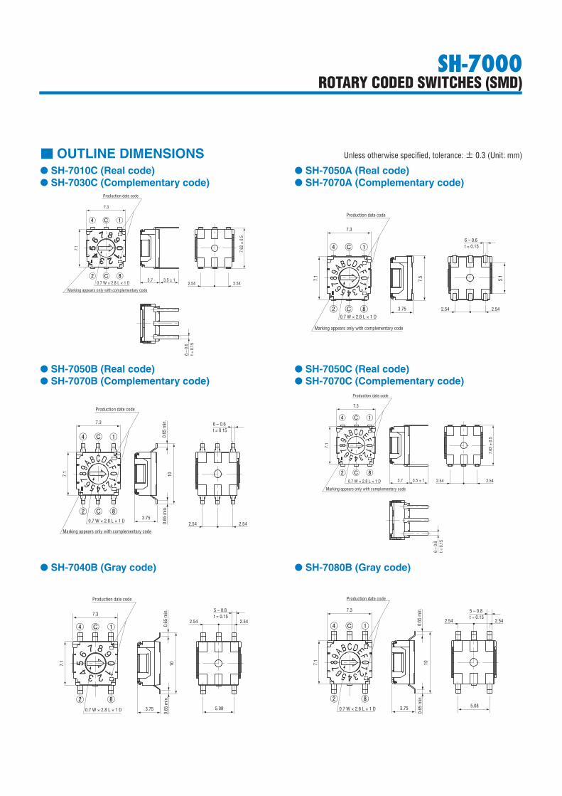
■ OUTLINE DIMENSIONS Unless otherwise specified, tolerance: ± 0.3 (Unit: mm)
● SH-7010A (Real code)● SH-7030A (Complementary code)
● SH-7010B (Real code)● SH-7030B (Complementary code)
7.1
7.3
0.7 W × 2.8 L × 1 D
Marking appears only with complementary code
⑧Ⓒ②
①Ⓒ④
Production date code
6 – 0.6t = 0.15
3.75
7.5
5.1
2.54 2.54
7.3
7.1
0.7 W × 2.8 L × 1D
Production date code
Marking appears only with complementary code
①Ⓒ④
⑧Ⓒ②
10
0.65
min
.0.
65 m
in.
3.75
6 – 0.6t = 0.15
2.54 2.54
{ } : Reference only
Flow : 260 ± 3 °C as the temperature in a pot of molten solder, immer sion from head of ter minal to backside of board,5 ~ 6 s, two times maximum
SH-7000ROTARY CODED SWITCHES (SMD)
■ OUTLINE DIMENSIONS Unless otherwise specified, tolerance: ± 0.3 (Unit: mm)
● SH-7010C (Real code)● SH-7030C (Complementary code)
● SH-7050B (Real code)● SH-7070B (Complementary code)
● SH-7050A (Real code)● SH-7070A (Complementary code)
● SH-7050C (Real code)● SH-7070C (Complementary code)
7.1
①Ⓒ④
⑧Ⓒ②
7.3
Marking appears only with complementary code
0.7 W × 2.8 L × 1 D
Production date code
0.65
min
.10
0.65
min
.
3.75
6 – 0.6t = 0.15
2.54 2.54
①Ⓒ④
⑧Ⓒ②
7.1
Production date code
7.3
Marking appears only with complementary code
0.7 W × 2.8 L × 1 D 3.7 3.5 ± 1
7.62
± 0
.5
2.54 2.54
6 –
0.6
t = 0
.15
● SH-7040B (Gray code) ● SH-7080B (Gray code)
7.1
①Ⓒ④
⑧②
7.3
0.7 W × 2.8 L × 1 D
Production date code
0.65
min
.10
0.65
min
.
3.75 5.08
5 – 0.8t = 0.15
2.54 2.54
7.1
①Ⓒ④
⑧②
7.3
Production date code
0.65
min
.10
0.65
min
.
3.75 5.08
5 – 0.8t = 0.15
2.54 2.54
0.7 W × 2.8 L × 1 D
7.1
Marking appears only with complementary code
0.7 W × 2.8 L × 1 D
①Ⓒ④
② ⑧Ⓒ
Production date code
7.3
3.5 ± 13.72.54 2.54
6 –
0.6
t = 0
.15
7.62
± 0
.5
7.1
7.3
Production date code
0.7 W × 2.8 L × 1 D
Marking appears only with complementary code
①Ⓒ④
⑧Ⓒ②
7.5 5.1
3.75 2.54 2.54
6 – 0.6t = 0.15
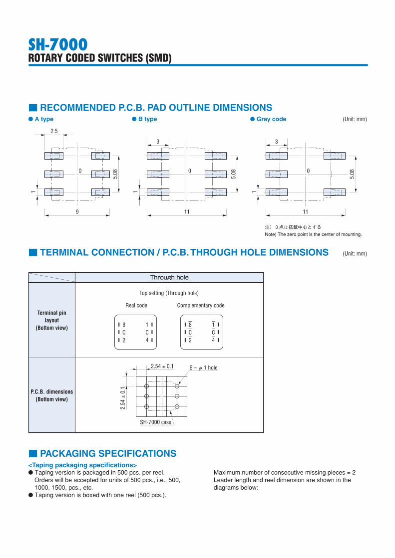
■ TERMINAL CONNECTION / P.C.B. THROUGH HOLE DIMENSIONS (Unit: mm)
Terminal pin layout
(Bottom view)
P.C.B. dimensions(Bottom view)
Through hole
2.54 ± 0.1
2.54
± 0
.1
SH-7000 case
6 – 1 holeφ
8 1
2C C
4
8 1
2C C
4
Real code
Top setting (Through hole)
Complementary code
2.54 ± 0.1
2.54
± 0
.1
SH-7000 case
6 – 1 holeφ
8 1
2C C
4
8 1
2C C
4
Real code
Top setting (Through hole)
Complementary code
SH-7000ROTARY CODED SWITCHES (SMD)
■ PACKAGING SPECIFICATIONS
Maximum number of consecutive missing pieces = 2Leader length and reel dimension are shown in the diagrams below:
<Taping packaging specifications>● Taping version is packaged in 500 pcs. per reel.
Orders will be accepted for units of 500 pcs., i.e., 500, 1000, 1500, pcs., etc.
● Taping version is boxed with one reel (500 pcs.).
■ RECOMMENDED P.C.B. PAD OUTLINE DIMENSIONS● A type ● B type ● Gray code (Unit: mm)
5.08
5.08
11
2.5
119
3
0
5.08
1
11
3
00
注)0点は搭載中心とするNote) The zero point is the center of mounting.
SH-7000ROTARY CODED SWITCHES (SMD)
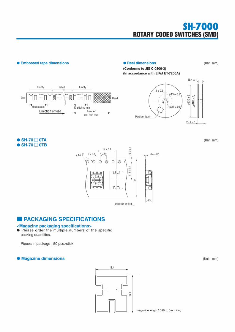
● SH-70 □ 0TA (Unit: mm)● SH-70 □ 0TB
0 9 8 765
4321
2 ± 0.1 4 ± 0.1
12 ± 0.1
Direction of feed
1.5φ +0.1 0 0.4 ± 0.1
4.3
24
11.5
± 0
.11.
75 ±
0.1
<Magazine packaging specifications>● Please order the multiple numbers of the specific
packing quantities.
Pieces in package : 50 pcs./stick
■ PACKAGING SPECIFICATIONS
● Magazine dimensions (Unit : mm)
13.4
17.2
magazine length:390 ± 3mm long
● Embossed tape dimensions ● Reel dimensions (Unit: mm)
(Conforms to JIS C 0806-3)(In accordance with EIAJ ET-7200A)
40 mm min. 20 pitches min.
400 mm min.Direction of feed
End Head
EmptyFilledEmpty
Leader
2 ± 0.5
25.4 ± 1
29.4 ± 1
Part No. label
13 ± 0.2φ
330 ±
2φ 10
0 ±
1φ
21 ± 0.8φ