rolling bearing steelsrolling bearing steels a technical and historical perspective
DESCRIPTION
A review of steel materiald for use in load bearing machinesTRANSCRIPT

Erwin V. ZaretskyGlenn Research Center, Cleveland, Ohio
Rolling Bearing Steels—A Technical and Historical Perspective
NASA/TM—2012-217445
April 2012

NASA STI Program . . . in Profile
Since its founding, NASA has been dedicated to the advancement of aeronautics and space science. The NASA Scientific and Technical Information (STI) program plays a key part in helping NASA maintain this important role.
The NASA STI Program operates under the auspices of the Agency Chief Information Officer. It collects, organizes, provides for archiving, and disseminates NASA’s STI. The NASA STI program provides access to the NASA Aeronautics and Space Database and its public interface, the NASA Technical Reports Server, thus providing one of the largest collections of aeronautical and space science STI in the world. Results are published in both non-NASA channels and by NASA in the NASA STI Report Series, which includes the following report types: • TECHNICAL PUBLICATION. Reports of
completed research or a major significant phase of research that present the results of NASA programs and include extensive data or theoretical analysis. Includes compilations of significant scientific and technical data and information deemed to be of continuing reference value. NASA counterpart of peer-reviewed formal professional papers but has less stringent limitations on manuscript length and extent of graphic presentations.
• TECHNICAL MEMORANDUM. Scientific
and technical findings that are preliminary or of specialized interest, e.g., quick release reports, working papers, and bibliographies that contain minimal annotation. Does not contain extensive analysis.
• CONTRACTOR REPORT. Scientific and
technical findings by NASA-sponsored contractors and grantees.
• CONFERENCE PUBLICATION. Collected papers from scientific and technical conferences, symposia, seminars, or other meetings sponsored or cosponsored by NASA.
• SPECIAL PUBLICATION. Scientific,
technical, or historical information from NASA programs, projects, and missions, often concerned with subjects having substantial public interest.
• TECHNICAL TRANSLATION. English-
language translations of foreign scientific and technical material pertinent to NASA’s mission.
Specialized services also include creating custom thesauri, building customized databases, organizing and publishing research results.
For more information about the NASA STI program, see the following:
• Access the NASA STI program home page at http://www.sti.nasa.gov
• E-mail your question via the Internet to help@
sti.nasa.gov • Fax your question to the NASA STI Help Desk
at 443–757–5803 • Telephone the NASA STI Help Desk at 443–757–5802 • Write to:
NASA Center for AeroSpace Information (CASI) 7115 Standard Drive Hanover, MD 21076–1320

Erwin V. ZaretskyGlenn Research Center, Cleveland, Ohio
Rolling Bearing Steels—A Technical and Historical Perspective
NASA/TM—2012-217445
April 2012
National Aeronautics andSpace Administration
Glenn Research Center Cleveland, Ohio 44135
Available from
NASA Center for Aerospace Information7115 Standard DriveHanover, MD 21076–1320
National Technical Information Service5301 Shawnee Road
Alexandria, VA 22312
Available electronically at http://www.sti.nasa.gov
Trade names and trademarks are used in this report for identification only. Their usage does not constitute an official endorsement, either expressed or implied, by the National Aeronautics and
Space Administration.
Level of Review: This material has been technically reviewed by technical management.

NASA/TM—2012-217445 1
Rolling Bearing Steels—A Technical and Historical Perspective
Erwin V. Zaretsky* National Aeronautics and Space Administration
Glenn Research Center Cleveland, Ohio 44135
Abstract Starting about 1920 it becomes easier to track the growth of bearing materials technology. Until
1955, with few exceptions, comparatively little progress was made in this area. AISI 52100 and some carburizing grades (AISI 4320, AISI 9310) were adequate for most applications. The catalyst to quantum advances in high-performance rolling-element bearing steels was the advent of the aircraft gas turbine engine. With improved bearing manufacturing and steel processing together with advanced lubrication technology, the potential improvements in bearing life can be as much as 80 times that attainable in the late 1950s or as much as 400 times that attainable in 1940. This paper summarizes the chemical, metallurgical and physical aspects of bearing steels and their effect on rolling bearing life and reliability. The single most important variable that has significantly increased bearing life and reliability is vacuum processing of bearing steel. Differences between through hardened, case carburized and corrosion resistant steels are discussed. The interrelation of alloy elements and carbides and their effect on bearing life are presented. An equation relating bearing life, steel hardness and temperature is given. Life factors for various steels are suggested and discussed. A relation between compressive residual stress and bearing life is presented. The effects of retained austenite and grain size are discussed.
Introduction Jacob Rowe applied for a British patent in 1734 for a rolling-element bearing. In his patent he defined
the advantages of such a bearing. Rowe stated that with the adoption of such bearings to …“wheel carriages… one Horse now will do the labor of two … and … I will suppose that there will be occasion to employ only twenty thousand Horses … instead of the 40,000 existing in the United Kingdom at an annual savings of 1,095,000 pounds per year.” B.W. Kelly (Ref. 1) in writing about Rowe said “that he was not able to find historical records that reported such sudden prosperity had occurred. As a result, he concluded that that the cost for keeping a horse that was not working was as much as it was for one that was in fact working.” Things really have not changed in over 275 years.
The rolling bearing materials used in Jacob Rowe’s era would have been wood, bronze and iron. Modern rolling-element bearing steel and metallurgy do not begin until about 1856 with the disclosure of the Bessemer process. In this process air is blown through molten pig iron to produce a relatively high grade of steel. This was followed 10 years later by the invention of open-hearth melting, which further improved quality and made steel far more accessible to industry. Bicycle bearing manufacturers were quick to take advantage of this new material. However, because heat treatment of steel was still an art known only to a few, most rolling-element bearings were probably made of unhardened steel. In 1879, British patent 869 was issued to J. Harrington and H. Brent for a hardened steel bushing, or inner shaft, fitted with a groove for balls. About the same time, W. Hillman of Coventry, England, constructed a machine for cutting balls from steel wire (Refs. 2 and 3).
In 1900, according to Stribeck (Ref. 4), the use of carbon and chromium steels for bearings gradually increased during the last quarter of the 19th Century as the need for bearings capable of reliably supporting heavy loads increased. He reported that water-hardened steel gave higher elastic limits and greater capacity than oil-hardened steel. In a discussion of the Stribeck paper, Hess (Ref. 4) presented chemical analyses of four bearing steels then in use. Hess (Ref. 4) stated that these bearing steels would
*Distinguished Research Associate
NASA/TM—2012-217445 2
“harden throughout and be uniformly hard and tough where durability and long life are wanted.” The chemistry of one of the French steels, no. 88, listed in the table closely matches that of American Iron and Steel Institute specification (AISI), AISI 52100. This steel was first specified about 1920 and is the most used bearing steel today (Refs. 2 and 3).
Starting about 1920 it becomes easier to track the growth of bearing materials technology. Until 1955, with few exceptions, comparatively little progress was made in this area. AISI 52100 and some carburizing grades (AISI 4320, AISI 9310) were adequate for most applications. Materials such as AISI 440 were available in those cases where improved corrosion resistance was required (Ref. 3). In one of the classic textbooks on bearing analysis written by Shaw and Macks (Ref. 5) in 1949, the only rolling-element bearing steel discussed was AISI 52100. Even as recently as 1957, in another authoritative text written by Wilcock and Booser (Ref. 6), the authors made only incidental note of the fact that AISI 52100 is not useful over 177 °C (350 °F). And, according to Wilcock and Booser (Ref. 6), “For temperatures above 177 °C (350 °F) bearing manufacturers have made small lots of bearings of AISI M–l and AISI M–10 tool steels. These steels retain their hardness to temperatures approaching 538 °C (1000 °F). Evidence available to date indicates that they operate satisfactorily, provided lubrication can be maintained.”
As discussed by Bamberger (Ref. 2) of General Electric Company Engine Division, Cincinnati, Ohio, the catalyst to quantum advances in all high-performance materials, including those steels used for bearings, was the advent of the aircraft gas turbine engine. The impact of the gas turbine engine on the growth of the aircraft industry after the Second World War created unprecedented needs for better materials and designs for rolling-element bearings. These needs included bearings for higher temperatures, higher speeds, and greater loads. The continuously increasing thrust-to-weight ratio for the aircraft jet engines required the use of smaller and lighter bearings. The reliability of these bearings became a major consideration because of system and mission complexities and because of the high costs involved (Refs. 2 and 3).
In order to assure long rolling bearing life and reliability for commercial, industrial and aerospace applications, materials, lubricants and design variables must be carefully considered and specified. The treatment of an alloy from the ore to the finished bearing can have a very significant effect on bearing performance, life and reliability. Experience has shown that different heats of the same material and process can produce life differences in the range of 2 to 1. It is therefore the objective of this paper to bring together and discuss from both a technical and historical perspective the chemical, metallurgical and physical aspects of bearing steels and their effect on rolling bearing life and reliability.
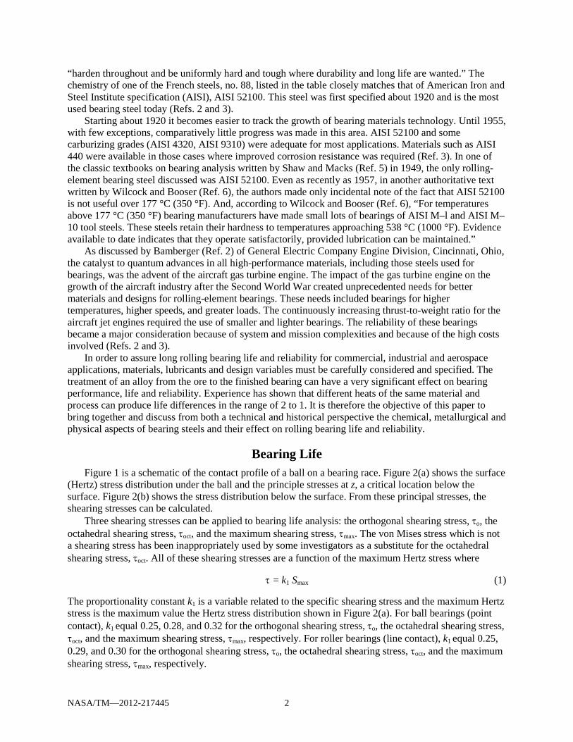
Bearing Life Figure 1 is a schematic of the contact profile of a ball on a bearing race. Figure 2(a) shows the surface
(Hertz) stress distribution under the ball and the principle stresses at z, a critical location below the surface. Figure 2(b) shows the stress distribution below the surface. From these principal stresses, the shearing stresses can be calculated.
Three shearing stresses can be applied to bearing life analysis: the orthogonal shearing stress, τo, the octahedral shearing stress, τoct, and the maximum shearing stress, τmax. The von Mises stress which is not a shearing stress has been inappropriately used by some investigators as a substitute for the octahedral shearing stress, τoct. All of these shearing stresses are a function of the maximum Hertz stress where
τ = k1 Smax (1)
The proportionality constant k1 is a variable related to the specific shearing stress and the maximum Hertz stress is the maximum value the Hertz stress distribution shown in Figure 2(a). For ball bearings (point contact), k1 equal 0.25, 0.28, and 0.32 for the orthogonal shearing stress, τo, the octahedral shearing stress, τoct, and the maximum shearing stress, τmax, respectively. For roller bearings (line contact), k1 equal 0.25, 0.29, and 0.30 for the orthogonal shearing stress, τo, the octahedral shearing stress, τoct, and the maximum shearing stress, τmax, respectively.
NASA/TM—2012-217445 3
Figure 1.—Schematic of contact profile of ball on raceway; a and
b, semiwidths of major and minor axes of Hertzian contact area, respectively.
For the analysis reported herein, only the maximum shearing stress is considered. The maximum shearing stress is one-half the maximum difference between the principal stresses:
2max
xz σ−σ=τ (2)
Moyer and Zaretsky (Ref. 7) discuss in detail “failure modes related to bearing life. The ultimate failure mode limiting bearing life is classical rolling-element fatigue of either a bearing race or a rolling element. The failure manifests itself as a spall limited to the width of the running track and the depth of the maximum shearing stresses a distance z below the contact surface where
z = k2 b (3)
The proportionality constant k2 is a variable related to the specific shearing stress and b is the semi minor axis of the contact ellipse (see Fig. 2). For ball bearings (point contact), k2 equal 0.50, 0.76, and 0.76 for the orthogonal shearing stress, τo, the octahedral shearing stress, τoct, and the maximum shearing stress, τmax, respectively. For roller bearings, (line contact) k2 equal 0.50, 0.79, and 079 for the orthogonal shearing stress, τo, the octahedral shearing stress, τoct, and the maximum shearing stress, τmax, respectively. The region or zone of maximum shearing stresses can be defined as the stressed volume beneath the Hertzian contact ranging from 0.50b to 0.79b depth below the stressed surface.
Generally, the spall begins in the region of maximum shearing stresses and propagates into a crack network. Most bearings, however, fail for other reasons. Failures other than those caused by classical rolling-element fatigue are considered avoidable if the bearing is properly designed, handled, installed, and lubricated and is not overloaded (Ref. 7).
Rolling-element fatigue is extremely variable but is statistically predictable depending on the steel type, steel processing, heat treatment, bearing manufacturing and type, and operating conditions. Sadeghi, et al. (Ref. 8) provide an excellent review of this failure mode.
Alley and Neu (Ref. 9) provide a recent attempt at modeling rolling-element fatigue. With improved bearing manufacturing and steel processing together with lubrication technology, the potential improvements in bearing life can be as much as 80 times that attainable in the late 1950s or as much as 400 times that attainable in 1940 (Ref. 3).

NASA/TM—2012-217445 4
Figure 2.—Subsurface stress field under point contact.
(a) Hertz stress distribution for ball on raceway showing principal stresses (σ, stress; τ, shear stress; and Smax, maximum Hertz stress) at depth z below surface. (b) Distribution of principal and shearing stress as function of depth z/b below surface.
Based on the 1947 work by Lundberg and Palmgren (Refs. 10 and 11) who use the orthogonal shearing stress, τo, for their analysis, the life of a ball or roller bearing based on rolling-element fatigue can be expressed in its most simplistic form as follows:

NASA/TM—2012-217445 5
p
PCLFL
=10 (4)
Equation (4) is benchmarked to pre-1940 air melt AISI 52100 steel where LF = 1. The L10 life, in millions of inner race revolutions, is the theoretical life that 90 percent of a bearing
population should equal or exceed without failure at their operating load P. C is defined as the theoretical load that a bearing can carry for a life of 1 million inner-race revolutions with a 90-percent probability of survival. The load-life exponent is p. And, LF is a life factor dependent on the bearing steel and its processing (Ref. 11).
Lundberg and Palmgren (Ref. 10) derive the load-life exponent p to be 3 for ball bearings and 4 for roller bearings. However, in their 1952 paper (Ref. 12), Lundberg and Palmgren modified their value of the load-life exponent p for roller bearings from 4 to 10/3. Their rationale for doing so was that various roller bearing types had one contact that is line contact and other that is point contact. They state “… as a rule the contacts between the roller and the raceways transforms from a point to a line for some certain load so that the life exponent varies from 3 to 4 for differing loading intervals within the same bearing.” The ANSI/ABMA (Ref. 13) and ISO (Ref. 14) Standards incorporate p = 10/3 for roller bearings. Computer codes for rolling-element bearings incorporate p = 4 for roller bearings and p = 3 for ball bearings (Ref. 11).
Bearing lives determined by using Equation (4) with the values of C given in bearing manufacturers’ catalogues are based on the “first evidence of fatigue.” This can be a tiny spall that may not significantly impair the function of the bearing. Thus, the actual useful life can be much longer. Society of Tribologists and Lubrication Engineers (STLE) life factors LF for various bearing steels are given in Table 1 (Ref. 3). It can be reasonably assumed that these life factors are benchmarked to air melt AISI 52100 steel at a maximum Hertz (contact) stress of 1.723 GPa (250 ksi). Table 2 provides the designation and chemistry of these and other representative bearing steels (Ref. 15).
TABLE 1.—LIFE FACTORS FOR BEARING STEELS (REF. 3)
Material Life factor, LF
Through-hardened steels AISI 52100 3 AISI M–10 2 AISI M–50 2 AISI T–1 (18–4–1) 2 Halmo 2 AISI M–1 .6 AISI M–2 .6
Corrosion-resistant steels AMS 5749 (BG–42) 2 AMS 5900 (CRB7) 2 AISI 440C .6
Case-carburized steels AMS 6278 (VIM–VAR M50 NiL) 4 AISI 4620 3 AISI 8620 2 AISI 9310 2 CBS 600 2 Vasco X–2 2 CBS 1000 2 AISI 8720 1.5

NASA/TM—2012-217445 6
TABLE 2.—REPRESENTATIVE BEARING AND GEAR STEELS (REF. 15)
Material Alloying element, percent by weight (balance Fe) Common
designation Description Reference
specifications C P
(max) S
(max) Mn Si Cr V W Mo Co Nb Ni Other
50100 Cr alloy steel UNS G 50986; AISI E 50100; AMS 6442 1.00 0.025 0.025 0.35 0.25 0.50 ----- ----- ----- ----- ----- ----- --------
51100 Cr alloy steel UNS G 51986; AISI E 51100; AMS 6440, 6444, 6447
1.00 .025 .025 .35 .25 1.00 ----- ----- ----- ----- ----- ----- --------
52100 Cr alloy steel UNS G 52986; AISI E 52100; AMS 6440, 6444, 6447
1.00 .025 .025 .35 .39 1.45 ----- ----- ----- ----- ----- ----- --------
MHT Al-modified bearing steel --------------------------- 1.03 .025 .025 .35 .35 1.50 ----- ----- ----- ----- ----- ----- 1.36 Al Halmo Bearing steel --------------------------- .56 .003 .008 .36 1.12 4.84 0.53 ----- 5.18 ----- ----- ----- ----------
M–1 High-speed tool steel UNS T 11301; AISI M–1 .80 .030 .030 .30 .30 4.00 1.00 1.50 8.00 ----- ----- ----- ----------
M–2 High-speed tool steel UNS T 11302; AISI M–2 .83 .030 .030 .30 .30 3.85 1.90 6.15 5.00 ----- ----- ----- ----------
M–10 High-speed tool steel UNS T 11310; AISI M–10 .85 .030 .030 .25 .30 4.00 2.00 ----- 8.00 ----- ----- ----- ----------
M–42 High-speed tool steel UNS T 11342; AISI M–42 1.10 .012 .007 .15 .17 3.77 1.15 1.66 9.51 7.99 ----- ----- ----------
M–50 High-speed tool steel UNS T 11350; AISI M–50; AMS 6490, 6491
.80 .030 .030 .30 .25 4.00 1.00 ----- 4.25 ----- ----- ----- ----------
M50 NiLa Carburized steel AMS 6278 .13 .030 .030 .30 .25 4.00 1.20 ----- 4.25 ----- ----- 3.50 ----------
T–1(18–4–1) High-speed tool steel UNS T 12001; AISI T–1; AMS 5626 .70 .030 .030 .30 .25 4.00 1.00 18.0 ----- ----- ----- ----- ----------
T–15 High-speed tool steel UNS T 12015; AISI T–15 1.52 .030 .030 .26 .25 4.70 4.90 12.5 b1.0 5.10 ----- ----- ----------
440C Hardenable Cr stainless steel UNS S 44004; AISI 440C; AMS 5618, 5630, 5880, 7445
1.03 .018 .014 b1.0 .41 17.3 .14 ----- .75 ----- ----- ----- ----------
AMS 5749 Martensitic stainless steel UNS S 42700; AMS 5749 1.15 .015 .010 .50 .30 14.5 1.20 ----- 4.00 ----- ----- ----- b.35 Cu
Vasco matrix II Gear steel --------------------------- .53 .014 .013 .12 .21 4.13 1.08 1.40 4.80 7.81 ----- .10 ---------- CRB–7 Bearing steel --------------------------- 1.10 .016 .003 .43 .31 14.0 1.03 ----- 2.02 ----- .32 ----- ----------
AMS 5900 Martensitic stainless steel UNS S 42800; AMS 5900 1.10 .015 .010 .40 .30 14.0 1.00 ----- 2.00 ----- ----- b.35 .25 Nb
9310a Ni-Cr-Mo alloy steel UNS G 93106; AISI 9310; AMS 6260, 6265, 6267
.10 .025 .025 .54 .28 1.18 ----- ----- .11 ----- ----- 3.15 ----------
CBS 600a Alloy steel UNS K 21940; AMS 6255 .19 .010 .010 .61 1.05 1.50 ----- ----- .94 ----- ----- .18 .07 Al
CBS 1000a Alloy steel --------------------------- .14 .018 .019 .48 .43 1.12 ----- ----- 4.77 ----- ----- 2.94 ---------- Vasco X–2a Gear steel --------------------------- .14 .011 .011 .24 .94 4.76 .45 1.40 1.40 .03 ----- .10 ----------
8620a Ni-Cr-Mo alloy steel UHS G 86200; AISI 8620; AMS 6274, 6276, 6277
.21 .035 .040 .80 .25 .50 ----- ----- .20 ----- ----- .55 ----------
EX–53a Gear steel --------------------------- .10 .009 .006 .37 .98 1.05 .12 2.13 3.30 ----- ----- ----- 2.07 Cu
3310a Alloy steel UNS G 33106; AISI 3310 .11 .025 .040 .52 .22 1.58 ----- ----- ----- ----- ----- 3.50 ----------
4320a Ni-Cr-Mo alloy steel UNS G 43200; AISI 4320 .20 .035 .040 .55 .25 .50 ----- ----- .25 ----- ----- 1.82 ----------
4620a Ni-Mo alloy steel UNS G 46200; AISI 4620; AMS 6294 .20 .035 .040 .55 .25 ----- ----- ----- .25 ----- ----- 1.82 ----------
4720a Ni-Cr-Ni alloy steel UNS G 47200; AISI 4720 .20 .035 .040 .55 .25 .45 ----- ----- .20 ----- ----- 1.05 ----------
Pyrowear 675 Carburized stainless steel --------------------------- .07 .005 .003 .65 .40 13.0 .60 ----- 1.80 5.40 ----- 2.60 ---------- aCarburized grades. bMaximum.
NASA/TM—2012-217445 7
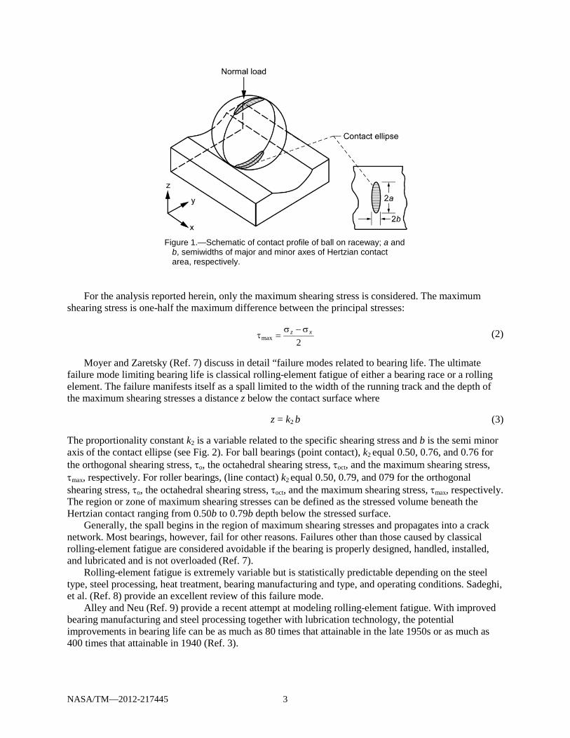
Steel Chemistry Through-Hardened Steels
In the 1950s through the 1960s the bearing industry assumed that materials with higher alloy content would have better hardness retention at elevated temperatures. It was reasoned that this would also result in higher ambient-temperature hardness as well as longer bearing life. Based on this assumption steel companies and research laboratories within the United States began to develop bearing steels with higher alloy content.
It is necessary to compare these steel and processing variables in rolling-element fatigue tests and/or actual bearing tests. Standard mechanical tests, such as tension and compression tests or rotating-beam tests, could not be correlated with rolling-element fatigue results (Ref. 16). Accordingly, a series of studies to verify the effect of increased alloying elements on rolling-element fatigue life was undertaken by the author and his colleagues at the NASA Lewis Research Center (now NASA Glenn Research Center), Cleveland, Ohio (Refs. 17 and 18).
Figure 3(a) summarizes the results of rolling-element fatigue tests conducted in the NASA Five-Ball Fatigue Tester (Ref. 17). Previous studies by others did not maintain the close control of operating and processing variables, such as material hardness, melting technique, and lubricant type and batch, required for a completely unbiased material comparison (Ref. 18). These tests comprised three groups each of eight through-hardened bearing steels. There were a total of 720 tests. All of the specimens for the specified steel came from the same heat of material and were manufactured and heat treated to the same hardness at the same time. All other variable were as carefully controlled. Contrary to expectation, rolling-element fatigue life decreases with increasing total content of alloying element in the steel. When present in high percentages these alloying elements appear to significantly decrease rolling element fatigue life.
Additional work, shown in Figure 3(b), was performed with 120-mm-bore, angular-contact ball bearings made from VAR AISI M–I, AISI M–42, AISI M–50, and WB–49 steels to verify the results in the NASA Five-Ball Fatigue Tester (Refs. 17 and 19). Bearings were tested at an outer-race temperature of 316 °C (600 °F). These four test series comprised a total of 120 bearings, 30 for each steel. The magnitudes of the differences seen in these bearing tests at 316 °C (600 °F) correlate well with the results of five-ball fatigue tests that are also shown in Figure 3(a). Using the AISI M–50 L10 life as a comparison, the AISI M–1 data from the five-ball fatigue tests and from the bearing tests agree remarkably well. WB–49 in the bearing tests and AISI M–42 in the five-ball fatigue tests, both of which alloys contain relatively high percentages of cobalt and have similar microstructures, show reasonably good agreement (Ref. 20).
These results completely changed previously held assumptions regarding the effect of bearing steel alloying elements on rolling-element fatigue life. As a result, by the mid-1980s AISI M-50 steel became the steel of choice for most high-temperature bearing applications over 149 °C (300 °F). For bearing temperatures less than 149 °C (300 °F), AISI 52100 steel with the lowest alloying content, has a longer fatigue life and is probably the most widely used bearing steel throughout the world. These steels are usually heat treated to Rockwell C hardness at room temperature of not less than 60. At operating temperature, it is a general requirement that the operating hot hardness be greater than Rockwell C 58.
Carburizing-Grade Steels
Bearings are required to tolerate substantial damage progression without catastrophic fracture during the interval between the onset of a problem and when routine maintenance identifies the need for repair (Refs. 21 and 22). Material toughness provides this capability. Fracture toughness is the material property that defines the stress required to initiate rapid fracture in the presence of a local defect (e.g., a fatigue spall). Initial defect size substantially affects fracture characteristics but is beyond the control of the designer. Tensile stresses, either application induced or residual, are necessary for rapid fracture to occur. These are somewhat controllable by the designer, but advanced applications will require tolerance to increased stress (Ref. 3).

NASA/TM—2012-217445 8
Figure 3.—Rolling-element fatigue life as a function of
total content of alloying elements tungsten, chromium, vanadium, molybdenum, and cobalt (Ref. 17).
Through-hardened materials, heat treated to Rockwell C 60 hardness, as is typical with bearing
components, have limited fracture toughness. The KIC is usually less than 24 MPa m1/2 (22 ksi in.1/2), depending upon heat treatment (Ref. 23) Materials with fracture toughness this low have limited bulk tensile stress capability if rapid fracture is to be avoided. A conservatively safe limit is 172.4 MPa (25 ksi). Applications requiring higher toughness will have to be made from a carburizing-grade steel (Ref. 3).
Carburizing-grade steels have reduced carbon content so that heat treatment normally results in moderate hardness and high toughness. High surface hardness, which is required for rolling-element bearing performance, is achieved by diffusing carbon into the surface, a process called carburizing, prior to heat treatment. Locally the steel is then a high-carbon alloy and is heat treatable to full hardness. The resulting structure has a surface layer with mechanical properties that are equivalent to those of traditional through-hardened bearing steels and a core that remains at low hardness, with corresponding high ductility and high fracture toughness. Surface-initiated defects (e.g., a spall) propagate cracks into the tough core before they reach critical size. The tough core prevents rapid and catastrophic fracture (Ref. 3).

NASA/TM—2012-217445 9
Fracture toughness of a material is inversely proportional to its carbon content and hardness. The carbon content also determines hardness. Fracture toughness can be improved without affecting hardness by adding nickel. When present in high-chromium, low-carbon steels, nickel causes the steel to become fully austenitic above 875 °C (1605 °F) where the steel is heat treated or carburized. Adding nickel also influences carbide size and distribution within the steel, which affects fatigue life. Recognizing this, Bamberger (Ref. 24) modified the chemistry of AISI M–50 steel by decreasing the amount of carbon and increasing the amount of nickel. He called this modified AISI M-50 steel M50 NiL (the “Ni” referring to increased nickel and the “L” to low carbon). The steel is also designated as Aerospace Material Specification (AMS) 6268.
M50 NiL, which is case carburized, has a core with a high fracture toughness KIC (over 60 MPa -m1/2; 50 ksi-in.1/2) than through hardened AISI M-50 (29 MPa -m1/2; 20 ksi-in.1/2). The M50 NiL core hardness is Rockwell C 43 to 45. M50 NiL has finer carbides (compounds of carbon and various alloying elements) dispersed more evenly within its microstructure than standard AISI M–50. Compressive residual stresses in excess of 210 MPa (30 ksi) are induced in the zone of maximum resolved shear stresses during carburization of M50 NiL. These residual stresses combined with the fine carbide structure will increase its rolling-element fatigue life over that of conventional AISI M–50 (Ref. 25).
Many carburized gear steels are also used as bearing steels. These carburized steels are primarily used for tapered roller bearings or other bearings such as cylindrical roller bearings where tight interference fits are required between the bearing bore and shaft. A tight interference fit will induce large tensile (hoop) stresses in the bearing inner ring that can cause catastrophic fracture failure of the ring and the bearing. As with AISI 52100 steel, for temperatures less than 149 °C (300 °F), AISI 9310 and AISI 8620 are usually the materials of choice. However, for bearing operating temperatures greater than 149 °C (300 °F), M50 NiL is the steel of choice.
Corrosion-Resistant Steels Although not normally a functional requirement, corrosion resistance is highly desirable because of
its potentially large effect on life-cycle cost. Alloy steels with high chromium content, greater than 12 percent, are considered corrosion resistant. However, although the chromium forms a passive chromium oxide layer at the surface that provides substantial protection, it is not inert and these alloys will corrode in hostile environments (Ref. 3).
Available corrosion-resistant bearing alloys include AISI 440C and the high-temperature variations such as AISI 440C Mod, Aerospace Material Specification (AMS) 5749 (VIM–VAR BG-42), AMS 5900 (VIM–VAR CRB7) and Pyrowear 675. AISI 440C is widely used in instrument bearings and in bearings for food-processing equipment. In addition, AISI 440C is the traditional alloy chosen for use in cryogenic rocket engine turbopumps such as those in the NASA Space Shuttle. AMS 5749 (VIM–VAR BG-42), AMS 5900 (VIM–VAR CRB7) and Pyrowear 675 are more recent developments (Ref. 3). For temperatures less than 149 °C (300 °F), AISI 440C is the corrosion resistant steel of choice. For temperatures greater than 149 °C (300 °F), AMS 5749(BG-42) is the steel of choice.
Steel Processing In the early years of the bearing industry acid- and base-refractory, air-melting methods were used to
process steel. Major advances in steel producing have occurred beginning in the 1950s by the introduction of vacuum-melting procedures. Vacuum processing reduces or eliminates the amount of nonmetallic inclusions, entrapped gases, and trace elements in structural alloys, resulting in substantially cleaner material. The two primary methods of vacuum processing are vacuum induction melting (VIM) and consumable-electrode vacuum melting (CEVM) also called vacuum arc remelting (VAR). In the early 1970s these two methods were combined, whereby the vacuum induction primary melt is vacuum arc remelted. This method, called VIM–VAR, produces much cleaner steel than either VIM or CEVM individually (Ref. 26). These results are shown in Figure 4.

NASA/TM—2012-217445 10
Figure 4.—Rolling-element fatigue life of AISI M–50 steel in rolling-contact fatigue
tester as a function of steel processing. Specimen diameter, 9.525 mm (3/8 in.); maximum Hertz stress, 4.8 GPa (700 ksi); speed, 12 500 rpm (Ref. 26).
TABLE 3.—LIFE FACTORS FOR MELTING PRACTICE (REF. 3) Processing Life factor,
LF Air melting (AM) 1 Vacuum processing (VP) or carbon vacuum degrassing (CVD) 1.5 Vacuum are remelting (VAR)a 3 Electroflux remelting (EFR)b 3 Vacuum are remelting-vacuum are remelting (VAR–VAR) 4.5 Vacuum induction melting-vacuum are remelting (VIM–VAR) 6 aAlso called consumable-electrode vacuum melting (CEVM). bAlso called electroslag remelting (ESR).
Although CEVM and VIM–VAR are the primary methods used today to produce materials such as AISI M–50, other vacuum processing methods have been developed, primarily aimed at improving AISI 52100. The effect of melting practice on rolling-element fatigue life is shown by the Society of Tribologists and Lubrication Engineers (STLE) life factors (LF) in Table 3 (Ref. 3). The product of the life factors for bearing steel from Table 1 and melting practice from Table 3 is used as a single life factor LF in Equation (1) to determine the bearing L10 life
Vacuum processing of bearing steel increases bearing life by eliminating hard oxide inclusions that act as stress raisers to initiate incipient failure. This results in an unforeseen secondary benefit. The fatigue life of the bearing steel becomes more sensitive to a reduction in stress. That is, as contact load or (Hertz) stress is decreased, bearing fatigue life is increased at a faster rate than with the air melted bearing steels.
As previously discussed, the load-life exponent p in Equation (1) is 3 for ball bearings and 4 for roller bearings based on pre 1940 air melt AISI 52100 steel. However, a reevaluation of the load-life relation (Refs. 27 to 29) based on a summary of published data by R.J. Parker and E.V. Zaretsky (Ref. 30)
NASA/TM—2012-217445 11
suggests that for post-1960 vacuum processed bearing steels, the load life exponent p equals 4 and 5 for ball and roller bearings, respectively. This accounts for another significant improvement in rolling bearing life and reliability.
Heat Treatment Steel Hardness
Hardness is an influential heat-treatment-induced variable. For most rolling bearing applications it is required that the Rockwell C hardness at operating temperature be 58 or higher. In general, the higher the hardness of the bearing steel at operating temperature, the longer the life. A relationship that approximates the effect of bearing material hardness on fatigue life has been developed (Refs. 20 and 31).
( )[ ]{ }60RCexp −= TmLF (5)
where m is an exponent relating material hardness and life (typically m = 0.1) and (RC)T is the Rockwell C hardness at operating temperature. It was assumed for the purpose of this relationship, which was obtained for AISI 52100, that all components in the rolling-element bearing (i.e., the rolling elements and the races) are of the same hardness. It was further assumed that this equation can be extended to other bearing steels. A 3 point increase in hardness can result in a 35 percent increase in bearing life. With the exception of AISI 52100 and other low-tempering-temperature bearing steels, most bearing steels can be expected to maintain their room-temperature hardness after soaking at elevated temperatures.
As was discussed for through-hardened steels, the bearing industry also assumed that materials with higher alloy content would have better hardness retention at elevated temperatures. A study to verify this assumption was undertaken at NASA Lewis Research Center (Refs. 32 to 34). Short-term, hot-hardness measurements were made for groups of through-hardened specimens of AISI 52100, M–1, M–50, 440C, Halmo, WB–49, WD65, and Matrix II. Measurements were also made of specimens of Super Nitralloy (5Ni-2A1) and case-carburized AISI 8620, CBS 600, CBS 1000, and Vasco X–2. The results for the AISI 52100 and the other through-hardened steels were normalized and are shown in Figure 5. These normalized data show that regardless of the initial hardness, the hot hardness of individual materials shows the same functional dependence. These results completely changed previously held assumptions (Ref. 20). These data can be represented by a straight line having the form:
( ) ( ) β∆α−= TRTT RCRC (6)
where (RC)T is the Rockwell C hardness at operating temperature; (RC)RT is the Rockwell C hardness at room temperature; ΔT is the difference between operating temperature and room temperature, α is a material constant, and β is a material exponent. Values of α and β for various bearing steels are given in Table 4.
To determine hardness effects at the bearing operating temperature, Equations (2) and (3) can be combined to obtain a life factor as follows:
( )[ ] ( ){ }( )β−α−−= RTTRT TTLF 60RC1.0exp (7)
where TRT is 22 °C (70 °F). Equation (7) is benchmarked to a Rockwell C hardness equal 60 where LF = 1.

NASA/TM—2012-217445 12
Figure 5.—Summary of short-term, hot-hardness,
through-hardened bearing steel data (Ref. 20).
NASA/TM—2012-217445 13
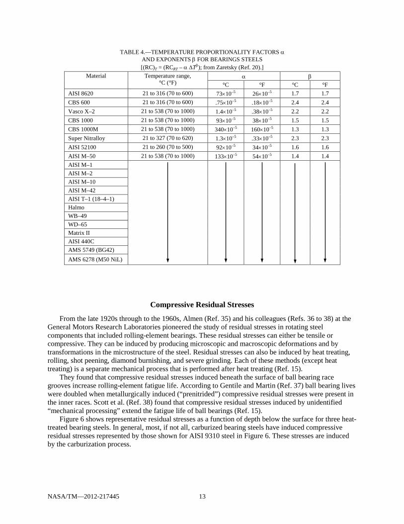
TABLE 4.—TEMPERATURE PROPORTIONALITY FACTORS α AND EXPONENTS β FOR BEARINGS STEELS [(RC)T = (RCRT – α ∆Tβ); from Zaretsky (Ref. 20).]
Material Temperature range, °C (°F)
α β °C °F °C °F
AISI 8620 21 to 316 (70 to 600) 73×10–5 26×10–5 1.7 1.7 CBS 600 21 to 316 (70 to 600) .75×10–5 .18×10–5 2.4 2.4 Vasco X–2 21 to 538 (70 to 1000) 1.4×10⁻⁵ .38×10–5 2.2 2.2 CBS 1000 21 to 538 (70 to 1000) 93×10–5 38×10–5 1.5 1.5 CBS 1000M 21 to 538 (70 to 1000) 340×10–5 160×10–5 1.3 1.3 Super Nitralloy 21 to 327 (70 to 620) 1.3×10⁻⁵ .33×10–5 2.3 2.3 AISI 52100 21 to 260 (70 to 500) 92×10–5 34×10–5 1.6 1.6 AISI M–50 21 to 538 (70 to 1000) 133×10–5 54×10–5 1.4 1.4 AISI M–1
AISI M–2 AISI M–10 AISI M–42 AISI T–1 (18–4–1) Halmo WB–49 WD–65 Matrix II AISI 440C AMS 5749 (BG42) AMS 6278 (M50 NiL)
Compressive Residual Stresses
From the late 1920s through to the 1960s, Almen (Ref. 35) and his colleagues (Refs. 36 to 38) at the General Motors Research Laboratories pioneered the study of residual stresses in rotating steel components that included rolling-element bearings. These residual stresses can either be tensile or compressive. They can be induced by producing microscopic and macroscopic deformations and by transformations in the microstructure of the steel. Residual stresses can also be induced by heat treating, rolling, shot peening, diamond burnishing, and severe grinding. Each of these methods (except heat treating) is a separate mechanical process that is performed after heat treating (Ref. 15).
They found that compressive residual stresses induced beneath the surface of ball bearing race grooves increase rolling-element fatigue life. According to Gentile and Martin (Ref. 37) ball bearing lives were doubled when metallurgically induced (“prenitrided”) compressive residual stresses were present in the inner races. Scott et al. (Ref. 38) found that compressive residual stresses induced by unidentified “mechanical processing” extend the fatigue life of ball bearings (Ref. 15).
Figure 6 shows representative residual stresses as a function of depth below the surface for three heat-treated bearing steels. In general, most, if not all, carburized bearing steels have induced compressive residual stresses represented by those shown for AISI 9310 steel in Figure 6. These stresses are induced by the carburization process.

NASA/TM—2012-217445 14
Figure 6.—Representative principal residual stress as a function of depth
below surface for heat-treated AISI M–50, AISI 9310, and M50 NiL (AMS 6278) (Ref. 3).
In 1965 E.V. Zaretsky (Refs. 15 and 39) and his colleagues at the NASA Lewis (now Glenn) Research Center published an equation relating rolling-element fatigue life to these compressive residual stresses. The maximum shearing stress τmax for a given contact stress is decreased by the presence of a compressive residual stress σr. This results in the following life factor due to residual stresses alone:
c
rLF
σ−τ
τ=
2/1max
max (8)
where exponent c is typically 9. For light to moderately loaded bearings a typical value of τmax is 414 MPa (60 ksi). For heavily loaded
bearings a typical value of τmax is 724 MPa (105 ksi). From Figure 6, assume AISI 9310 as the bearing steel. The compressive residual stress, σr, is 200 MPa (29 ksi). From Equation (8), for a lightly loaded bearing, LF ≈ 12. For a heavily loaded bearing, LF ≈ 3.8. These life factors can be applied in Equation (1) together with the other life factors discussed. However, when bearing life results are analyzed independent of these residual stresses, the load-life exponent p appears to increase from their accepted values (Ref. 40).
Investigators have misinterpreted these results caused by the presence of residual stresses as a “fatigue limit” (Ref. 41). They have incorporated them into bearing life predictions and in some cases bearing manufacturer catalogues (Ref. 42). The concept of a fatigue limit has also been incorporated into an ISO standard (Ref. 43) for bearing life prediction for AISI 52100 steel where there are no residual stresses in the as heat treated steel (Ref. 42). This can result in bearing life over prediction and/or undersizing a bearing for a particular application (Refs. 41 and 42).
There are two problems associated with the use of a fatigue limit for bearing steels. The first problem is as discussed above, the form of the equation as expressed in the ISO standard (Ref. 43) may not reflect

NASA/TM—2012-217445 15
a fatigue limit but the presence of a compressive residual stress. The second problem is that there are no data in the open literature that would justify the use of a fatigue limit for through-hardened bearing steels such as AISI 52100 and AISI M-50 (Refs. 41 and 42).
In 2007 Sakai (Refs. 44 and 45) presented stress life rotating bending fatigue data from six different laboratories in Japan for AISI 52100 steel. He also presented stress-life fatigue data for axial loading. The resultant lives were in excess of one billion (>109) stress cycles at a maximum shearing stress τmax as low as 350 MPa (51 ksi) without an apparent fatigue limit.
In 2008 Tosha, et al., (Ref. 46) of Meiji University in Japan reported rotating bending stress-life fatigue tests for through hardened bearing steels having Rockwell C hardness above 58. The results of these tests at maximum shearing stresses τmax as low as 480 MPa (70 ksi) produced fatigue lives in excess of 100 million (>108) stress cycles without the manifestation of a fatigue limit.
In 2009, in order to verify the results of Sakai (Refs. 44 and 45) and Tosha, et al. (Ref. 46), Shimizu, et al. (Ref. 47), also of Meiji University, published the results from six groups of AISI 52100 bearing steel specimens using four-alternating torsion fatigue tests rigs to determine whether a fatigue limit exists or not and to compare the resultant shear stress-life relation with that used for rolling-element bearing life prediction (Ref. 42). The results of these tests at maximum shearing stresses τmax as low as 500 MPa (76 ksi) produced fatigue lives in excess of 10 million (>107) stress cycles without a fatigue limit. Shimizu, et al. (Ref. 47). reported that the resultant fatigue life was inversely related to the shearing stress to the 10.34 power (Ref. 42).
Retained Austenite
In the early 1960s a major U.S. aircraft engine company had to discard unused rolling-element bearings made from AISI M-50 because their bore diameter had increased from that specified for the engine shaft diameter (in a personal communication with E.N. Bamberger, General Electric Company, February 1963). This expansion in bore size was attributed to the presence of large amounts of retained austenite in the microstructure of the steel. The retained austenite transformed to martensite and bainite on the shelf at room temperature. As a result, for most critical aerospace applications, the retained austenite is limited to 2 to 5 percent. However, for noncritical applications, higher amounts of retained austenite are allowed or may, in some instances, be uncontrolled. Experience has suggested that lower values of retained austenite are preferable for reliable bearing operation (Ref. 15).
L.R. Waldmiller of Frost, Inc. (in a personal communication, December 1994) described unrun, carburized, 12.7-mm (0.5-in.) diameter AISI 1022 balls having 40 to 50 percent retained austenite. The balls lost a portion of the case material while at room temperature due to transformation of the retained austenite. The lost material had the appearance of a “skullcap” and the phenomenon was referred to as “capping.” He reported that the phenomenon also occurs during bearing operation. The same material with a lower amount of retained austenite did not experience capping (Ref. 15).
In general, for a given through-hardened material the amount of retained austenite increases with increasing material hardness. Experience has also shown that test rollers made from AISI 52100 of Rockwell C hardnesses greater than 63 will have sufficient austenite-to-martensite transformation during rolling contact to alter the surface waviness and cause early surface spalling (Ref. 15).
Johnston et al. (Ref. 48) studied the effect of the decomposition of retained austenite and the inducement of compressive residual stress as a result of bearing operation. What is unique for their data is that the magnitudes of the compressive residual stresses are directly proportional to the decomposition of retained austenite (Ref. 15).
Changes in microstructure (phase transformations) have been reported to occur in the same areas as the maximum induced residual stress (Refs. 36 and 49). Under some conditions of extremely high contact stresses, nonmicrostructural alteration was apparent after significant residual stresses had been induced in a few cycles (Ref. 49). Muro and Tsushima (Ref. 50) proposed that the induced residual stresses and the microstructural alterations are independent phenomena (Ref. 15).

NASA/TM—2012-217445 16
Research performed by Zhu et al. (Ref. 51) in 1985 on carburized rollers suggested that the structural change in the zone of maximum resolved shearing stresses observed by Jones (Ref. 52) in 1947 and later by Carter (Ref. 53) in 1960 as well as others is a manifestation of retained austenite transforming to martensite under cyclic Hertzian stress conditions. A combination of thermal and strain energy and time is believed to cause this change (Ref. 15).
Grain Size
It is generally accepted in the bearing industry that prior austenite grain size should be ASTM number 8 or finer and that individual grains should not exceed ASTM number 5 (Ref. 54). The higher the ASTM number, the finer the grain size. The 1960 work of R.A. Baughman (Ref. 55) suggested that rolling-element fatigue life increases with finer grain sizes (Ref. 20). A recent analysis of grain size and orientation on rolling-element fatigue life was performed by N. Weinzapfel, et al. (Ref. 56).
Carbides
Residual carbides are those carbides that do not go completely into solution during austenitizing and are a function of the alloying elements and raw material processing. In contrast, hardening carbides precipitate upon aging at the tempering temperature. The carbides referred to in the following paragraphs are the residual carbides.
Carbide composition has been found to vary among steel producers. Heat treating steel ingots creates large, extremely hard metal carbides (MC), considered to be essentially a vanadium carbide, which can act as asperities in the bearing surface (Ref. 57). J.E. Bridge, et al. (Ref. 58) identified the primary carbides in AISI M–50 as MC and M2C. Pearson and Dickinson (Ref. 57) found that the M2C carbides contain a high percentage of molybdenum and that in a bearing ball under thin film elastohydrodynamic (EHD) lubrication conditions they can cause distress or peeling of the bearing race surfaces. The carbide “stick out” has been attributed in whole or in part to an excessive rate of grinding in the manufacture of bearing balls made from AISI M-50 steel.
Parker et al. (Refs. 17, 59, and 60) have shown an interrelation among steel alloy content, median residual carbide size, number of residual carbide particles per unit area, percentage of residual carbide area in through hardened bearing steels, and rolling-element fatigue life. As the percent of alloying elements increase in a steel the number and size of the carbides increase (Refs. 61 and 62). Subsequent research by Parker and Bamberger (Ref. 63) for AMS 5749 steel further substantiated the negative effect of large carbide size and banded carbide distribution on rolling-element fatigue life.
Pearson and Dickinson (Ref. 57) verified the observations of Butterfield and T.R. McNelley (Ref. 64), who reported voids of the order of 1 μm (40 μin.) adjacent to carbides of AISI M–50 steel. This work (Ref. 64) suggested that these voids form during bearing operation at the site of the carbide tip and can act as a nucleus for crack initiation in the subsurface zone of maximum shear stresses. The large carbides act as stress raisers to initiate an incipient crack that results in a rolling-element fatigue spall. The effect of carbides on rolling-element fatigue life is reflected in the life factors of Table 1 (Ref. 15).
In general, case carburized bearing steels, with the exception of M50 NiL, have a more course and larger carbide structure when compared to through hardened bearing steels such as AISI 52100 or AISI M-50. However, this disadvantage is more than offset by the compressive residual stresses induced into the case by the carburization process.
Summary In order to assure long rolling-element bearing life and reliability for commercial, industrial and
aerospace applications, materials, lubricants and design variables must be carefully considered and specified. The catalyst to quantum advances in high-performance rolling-element bearing steels was the advent of the aircraft gas turbine engine. The reliability of these bearings became a major consideration
NASA/TM—2012-217445 17
because of system and mission complexities and because of the high costs involved. With improved bearing manufacturing and steel processing together with advanced lubrication technology, the potential improvements in bearing life can be as much as 80 times that attainable in the late 1950s or as much as 400 times that attainable in 1940. The following summarizes the chemical, metallurgical and physical aspects of bearing steels and their effect on rolling bearing life and reliability:
(1) For temperatures less than 149 °C (300 °F) the bearing steels of choice are: through-hardened,
AISI 52100; case-carburized, AISI 8620 and AISI 9310; and corrosion-resistant, AISI 440C. For temperatures greater than 149 °C (300 °F) the bearing steels of choice are: through-hardened, AISI M-50; case-carburized, M50 Nil; and corrosion-resistant, BG-42.
(2) Vacuum processing of bearing steel reduces or eliminates the amount of nonmetallic inclusions, entrapped gases, and trace elements in structural alloys, resulting in substantially cleaner material and significantly longer bearing life.
(3) For a post-1960 vacuum processed bearing steels such as AISI 52100 and AISI M-50, the values for the load life-exponent p, where life is inversely proportional to load to the exponent p, increased from 3 and 4 for ball and roller bearings, respectively, to 4 and 5.
(4) Minimum hardness for bearing steel at operating temperature should not be less than Rockwell C 58. Bearing life increases with increasing steel hardness at operating temperature. A 3 point increase in hardness can result in a 35 percent increase in bearing life. For M-Series bearing steels, the change in hardness with temperature is independent of alloy content.
(5) Bearing steels with high chromium content, greater than 12 percent, such as AISI 440 °C are considered corrosion resistant. Although the chromium forms a passive chromium oxide layer at the surface that provides substantial protection, it is not inert and these alloys will corrode in hostile environments.
(6) Compressive residual stresses induced or present from heat treatment beneath the surface of bearing steel components increase rolling-element fatigue life and can alter the Hertz stress-life relation. A compressive residual stress of 200 MPa (29 ksi) can increase bearing life for a lightly loaded bearing by a life factor, LF ≈ 12. For a heavily loaded bearing, LF ≈ 3.8.
(7) For most critical aerospace applications, retained austenite is limited to 2 to 5 percent. However, for noncritical applications, higher amounts of retained austenite are allowed or may, in some instances, be uncontrolled. Experience has suggested that lower values of retained austenite are preferable for reliable bearing operation.
(8) Rolling-element fatigue life increases with finer grain sizes. Prior austenite grain size should be ASTM number 8 or finer and that individual grains should not exceed ASTM number 5. The higher the ASTM number, the smaller the grain size.
(9) There is an interrelation among steel alloy content, median residual carbide size, number of residual carbide particles per unit area, percentage of residual carbide area, and rolling-element fatigue life. The large carbides act as stress raisers to initiate an incipient crack that results in a rolling-element fatigue spall. As the percent of alloying elements increase in through-hardened bearing steel, the number and size of the carbides increase.
(10) Case-carburized bearing steels, with the exception of M50 NiL, have a more course and larger carbide structure when compared to through hardened bearing steels such as AISI 52100 or AISI M-50. However, this disadvantage is more than offset by the compressive residual stresses induced into the case by the carburization process.
References 1. Kelly, B.W., (1970), “Lubrication of Concentrated Contacts – The Practical Problem,”
Interdisciplinary Approach to the Lubrication of Concentrated Contacts, P. M. Ku, ed., National Aeronautics and Space Administration, Washington, D.C., NASA SP–237, pp. 1–26.
NASA/TM—2012-217445 18
2. Bamberger, E.N., (1980), “Materials for Rolling Element Bearings,” Bearing Design—Historical Aspects, Present Technology and Future Problems, W.J. Anderson, ed., ASME, New York, pp. 1–46.
3. Anderson, W.J., Bamberger, E.N., Poole, W.E., Thom, R.L., and Zaretsky, E.V., (1992), “Materials and Processing,” STLE Life Factors for Rolling Bearings, E.V. Zaretsky, ed., Society of Tribologists and Lubrication Engineers, Park Ridge, IL, pp. 71–128.
4. Stribeck, R., (1900), “Reports From the Central Laboratory for Scientific Investigation,” Translation by H. Hess, 1907, ASME Trans., 29, pp. 420–466.
5. Shaw, M.C. and Macks, E.F., (1949), Analysis and Lubrication of Bearings, McGraw-Hill Book Co., New York.
6. Wilcock, D.F. and Booser, E.R., (1957), Bearing Design and Application, McGraw-Hill Book Co., New York.
7. Moyer, C.A., and Zaretsky, E.V., (1992), “Failure Modes Related to Bearing Life,” STLE Life Factors for Rolling Bearings, E.V. Zaretsky, ed., Society of Tribologists and Lubrication Engineers, Park Ridge, IL, pp. 47–69.
8. Sadeghi, F., Jalalahmadi, B., Slack, T.S., Raje, N., and Arakere, N.K., (2009), “A Review of Rolling-Contact Fatigue,” Jour. of Tribology, ASME Trans., 131, 4, Art. No. 041403, Oct 2009.
9. Alley, E.S., and Neu, R.W., (2010), “Microstructure-Sensitive Modeling of Rolling Contact Fatigue,” International Jour. of Fatigue, 32, 5, pp. 841–850.
10. Lundberg, G. and Palmgren, A., (1947), “Dynamic Capacity of Rolling Bearings,” Acta Polytechnica, Mechanical Engineering Series, Vol. 1, No. 3, pp. 1–50.
11. Zaretsky, E.V., (2010), “Rolling Bearing Life Prediction, Theory, and Application,” Recent Developments in Wear Prevention, Friction and Lubrication, G.K. Nikas, ed., Research Signpost, Kerala, India, pp. 45–136.
12. Lundberg, G., and Palmgren, A., 1952, “Dynamic Capacity of Roller Bearings,” Acta Polytechnica, Mechanical Engineering Series, Vol. 2, No. 4, pp. 243–247.
13. ANSI/AFBMA 11 – 1990, (1990), “Load Rating and Fatigue Life for Roller Bearings,” The Anti-Friction Bearing Manufacturers Association, Washington, DC.
14. ISO 281: 1990(E), (1990), Rolling Bearing – Dynamic Load Ratios and Rating Life,” International Organization for Standards, Geneva.
15. Zaretsky, E. V., (1997), “Rolling Bearing and Gear Materials,” Tribology for Aerospace Applications, E. V. Zaretsky, ed., STLE SP–37, Society of Tribologists and Lubrication Engineers, Park Ridge, IL, pp. 325–451.
16. Carter, T.L., Zaretsky, E.V., and Anderson, W.J., (1960), “Effect of Hardness and Other Mechanical Properties on Rolling-Contact Fatigue Life of Four High-Temperature Bearing Steels,” NASA TN D–270, National Aeronautics and Space Administration, Washington, D.C.
17. Parker, R.J., and Zaretsky, E.V., (1972), “Rolling-Element Fatigue Lives of Through- Hardened Bearing Materials,” Journal of Lubrication Technology, Vol. 94, No. 2, pp. 165–173.
18. Zaretsky, E.V., Parker, R.J., and Anderson, W.J., (1982), “NASA Five-Ball Fatigue Tester-Over 20 Years of Research,” Rolling Contact Fatigue Testing of Bearing Steels, J.J.C. Hoo, ed., ASTM STP–771, ASTM, Philadelphia, PA, pp. 5–45.
19. Bamberger, E.N. and Zaretsky, E.V., (1971), “Fatigue Lives at 600 °F of 120-Millimeter-Bore Ball Bearings of AISI M–1, and WB–49 Steels,” NASA TN D–6156, National Aeronautics and Space Administration, Washington, D.C.
20. Zaretsky, E.V., (1988), “Selection of Rolling-Element Bearing Steels for Long-Life Application.” J.J.C., Hoo, ed., Effect of Steel Manufacturing Processes on the Quality of Bearing Steels, ASTM STP–987, ASTM, Philadelphia, pp. 5–43.
21. Clark, J.C., (1975), “Fracture Failure Modes in Lightweight Bearings,” Journal of Aircraft, 12, 4, pp. 383–387.
22. Clark, J.C., (1985), “Fracture Tough Bearings for High Stress Applications,” AIAA Paper 85–1138.

NASA/TM—2012-217445 19
23. Bamberger, E.N., Averbach, B.L., Pearson, P.K., (1985), “Improved Fracture Toughness Bearings,” AFWAL TR–84–2103. (Avail. NTIS, AD–B094304L.)
24. Bamberger, E.N., (1983), “Status of Understanding for Bearing Materials,” Tribology in the ’80’s, Vol. 2, NASA CP–2300–VOL–2, W.F. Loomis, ed., National Aeronautics and Space Administration, Washington, D.C., pp. 773–794.
25. Philip, T.V., (1986), “New Bearing Steel Beats Speed and Heat,” Power Transmission Design, 28, 6, pp. 43–46.
26. Bamberger, E.N., and Clark, J.C., (1982), “Development and Application of the Rolling Contact Fatigue Test Rig,” Rolling Contact Fatigue Testing of Bearing Steels, ASTM STP–771, J.J.C. Hoo, ed., American Society for Testing and Materials, Philadelphia, PA, pp. 85–106.
27. Poplawski, J. V., Peters, S. M., and Zaretsky, E. V., (2001), “Effect of Roller Profile on Cylindrical Roller Bearing Life Prediction – Part I: Comparison of Bearing Life Theories,” STLE Tribology Trans., 44, 3, pp. 339–350.
28. Poplawski, J. V., Peters, S. M., and Zaretsky, E. V., (2001), “Effect of Roller Profile on Cylindrical Roller Bearing Life Prediction – Part II Comparison of Roller Profiles” STLE Tribology Trans., 44, 3, pp. 417–427.
29. Zaretsky, E.V., Lewicki, D.G., Savage, M., and Vlcek, B.L., (2007)”Determination of Turboprop Reduction Gearbox System Fatigue Life and Reliability,” Tribology Trans., 50, 4, pp. 225–262.
30. Parker, R.J., and Zaretsky, E.V., (1972), “Reevaluation of the Stress-Life Relation in Rolling-Element Bearings,” NASA TN D–6745, National Aeronautics and Space Administration, Washington, D.C.
31. Zaretsky, E.V., Parker, R.J., and Anderson, W.J., (1965), “Effect of Component Differential Hardness on Rolling-Contact Fatigue and Load Capacity,” NASA TN D–2640, National Aeronautics and Space Administration, Washington, D.C.
32. Chevalier, J.L., Dietrich, M.W., and Zaretsky, E.V., (1972), “Short-Term Hot Hardness Characteristics of Rolling-Element Steels,” NASA TN D–6632, National Aeronautics and Space Administration, Washington, D.C.
33. Chevalier, J.L., Dietrich, M.W., and Zaretsky, E.V., (1973), “Hot Hardness Characteristics of Ausformed AISI M–50, Matrix II, WD–65, Modified AISI 440–C, and Super Nitralloy,” NASA TN D–7244, National Aeronautics and Space Administration, Washington, D.C.
34. Anderson, N.E. and Zaretsky, E.V., (1975), “Short-term Hot-Hardness Characteristics of Five Case-Hardened Steels,” NASA TN D–8031, National Aeronautics and Space Administration, Washington, D.C.
35. Almen, J. O., “Effects of Residual Stress on Rolling Bodies,” (1962), Rolling Contact Phenomena, J. B. Bidwell, ed., Elsevier, New York, pp. 400–431.
36. Gentile, A.J., Jordan, E.F., and Martin, A.D., (1965), “Phase Transformations in High-Carbon, High-Hardness Steels Under Contact Loads,” AIME Transactions, Vol. 233, No. 6, pp. 1085–1093.
37. Gentile, A.J., and Martin, A.D., 1965, “The Effect of Prior Metallurgically Induced Compressive Residual Stress on the Metallurgical and Endurance Properties of Overload-Tested Ball Bearings,” ASME Paper 65–WA/CF–7.
38. Scott, R.L., Kepple, R.K., and Miller, M.H., 1962, “The Effect of Processing-Induced Near-Surface Residual Stress on Ball Bearing Fatigue,” Rolling Contact Phenomena, J.B. Bidwell, ed., Elsevier, pp. 301–316.
39. Zaretsky, E.V., Parker, R.J., Anderson, W.J., and Miller, S.T., (1965), “Effect on Component Differential Hardness on Residual Stress and Rolling–Contact Fatigue,” NASA TN D–3101, National Aeronautics and Space Administration, Washington, D.C.
40. Oswald, F.B., Zaretsky, E.V. and Poplawski, J.V. (2011), “Relation Between Residual and Hoop Stresses and Rolling Bearing Fatigue Life,” Presented at the 2011 STLE Annual Meeting, May 15–19, 2011, Atlanta, Georgia.

NASA/TM—2012-217445 20
41. Zaretsky, E.V., Poplawski, J.V., and Peters, S.M., (1996), “Comparison of Life Theories for Rolling-Element Bearings,” STLE Tribology Trans., 39, 2, pp. 237–247, Discussion by E. Ioannides and T.A. Harris, pp.247–248; Authors’ reply, pp. 501–503.
42. Zaretsky, E.V., (2010), “In Search of a Fatigue Limit: A Critique of ISO Standard 281:2007,” Tribology & Lubrication Technology, STLE, 66, 8, Aug. 2010, pp. 30–40.
43. ISO 281:2007, (2007), “Rolling Bearings—Dynamic Load Ratings and Rating Life,” International Organization for Standardization, Geneva.
44. Sakai, T., (2007), Review and Prospects for Current Studies on Very High Cycle Fatigue of Metallic Materials for Machine Structure Use,” Proc. 4th International Conference on Very High Cycle Fatigue (VHCF–4), TMS (The Minerals, Metals & Materials Society), pp. 3–12.
45. Sakai, T., Takeda, M., Shiozawa, K., Ochi, Y., Nakajima, M., Nakamura, T., and Oguma, Y., (2000), “Experimental Reconfirmation of Characteristic S-N Property for High Carbon Bearing Steel in Wide Life Region in Rotating Bending,” J. Soc. Mat. Sci. Japan, 49, 7, pp. 779–785 (in Japanese).
46. Tosha, K., Ueda, D., Shimoda, H. and Shimizu, S., (2008), “A Study on P-S-N Curve for Rotating Bending Fatigue Test for Bearing Steel,” STLE Tribology Trans., 51, 2, pp. 166–172.
47. Shimizu, S., Tsuchiya, K., and Tosha, K., (2009), “Probabilistic Stress-Life (P-S-N) Study on Bearing Steel Using Alternating Torsion Life Test,” STLE Tribology Trans., 52, 6, pp. 807–816.
48. Johnston, G.B., Anderson, T., Amerongen, E.V., and Voskamp, A., (1982), “Experience of Element and Full-Bearing Testing of Materials over Several Years,” Rolling Contact Fatigue Testing of Bearing Steels, ASTM STP–771, J.J.C. Hoo, ed., American Society for Testing and Materials, Philadelphia, PA, pp. 190–195.
49. Bush, J.J., Grube, W.L., and Robinson, G.H., (1962), “Microstructural and Residual Stress Changes in Hardened Steel due to Rolling Contact,” Rolling Contact Phenomena, J.B. Bidwell, ed., Elsevier, New York, pp. 365–399.
50. Muro, H., and Tsushima, N., (1970), “Microstructural Microhardness and Residual Stress Changes Due to Rolling Contact,” Wear, 15, pp. 309–330.
51. Zhu, D., Wang, F., Cai, Q., Zheng, M., and Cheng, Y., (1985), “Effect of Retained Austenite on Rolling Element Fatigue and Its Mechanism,” Wear, 105, pp. 223–234.
52. Jones, A.B., (1947), “Metallographic Observations of Ball Bearing Fatigue Phenomena,” Symposium on Testing of Bearings, American Society for Testing and Materials, Philadelphia, PA, pp. 35–52.
53. Carter, T.L., (1960), “A Study of Some Factors Affecting Rolling-Contact Fatigue Life,” NASA TR R–60, National Aeronautics and Space Administration, Washington, D.C.
54. Irwin, A.S., Anderson, W.J., and Derner, W.J., (1985), “Review and Critical Analysis—Rolling-Element Bearings for System Life and Reliability,” NASA CR–174710, National Aeronautics and Space Administration, Washington, D.C.
55. Baughman, R.A., (1960), “Effect of Hardness, Surface Finish, and Grain Size on Rolling Contact Fatigue Life of M–50 Bearing Steel,” Jour. of Basic Engineering, ASME Trans., 82, 2, pp. 287–294.
56. Weinzapfel, N., Sadeghi, F., and Bakolas, V., (2010), “An Approach for Modeling Material Grain Structure in Investigations of Hertzian Subsurface Stresses and Rolling Contact Fatigue,” Jour. of Tribology, Trans. ASME, 132, Oct. 2010, pp. 041404-1–041404-12.
57. Pearson, P.K., and Dickinson, T.W., (1988), “The Role of Carbides in Performance of High-Alloy Bearing Steels,” Effect of Steel Manufacturing Processes on the Quality of Bearing Steels, ASTM STP–987, J.J.C. Hoo, ed., American Society for Testing and Materials, Philadelphia, PA, pp. 113–131.
58. Bridge, J.E., Maniar, G.N., and Philip, T.V., (1971), “Carbides in M–50 High Speed Steel,” Metallurgical Transactions, 2, pp. 2209–2214.
59. Parker, R.J., Zaretsky, E.V., and Dietrich, M.W., (1971), “Rolling-Element Fatigue Lives of Four M-Series Steels and AISI 52100 at 150 °F,” NASA TN D–7033, National Aeronautics and Space Administration, Washington, D.C.

NASA/TM—2012-217445 21
60. Parker, R.J., Zaretsky, E.V., and Dietrich, M.W., (1971), “Rolling-Element Fatigue Lives of AISI T–1, AISI M-42, AISI 52100, and Halmo at 150 °F,” NASA TN D–6179, National Aeronautics and Space Administration, Washington, D.C.
61. Chevalier, J.L., and Zaretsky, E.V., (1972), “Effect of Carbide Size, Area, and Density on Rolling-Element Fatigue,” NASA TN D–6835, National Aeronautics and Space Administration, Washington, D.C.
62. Chevalier, J.L., Zaretsky, E.V., and Parker, R.J., (1973), “A New Criterion for Predicting Rolling-Element Fatigue Lives of Through-Hardened Steels,” Journal of Lubrication Technology, 95, 3, pp. 287–297.
63. Parker, R.J, and Bamberger, E.N., 1983, “Effect of Carbide Distribution on Rolling- Element Fatigue Life of AMS 5749,” NASA TP–2189, National Aeronautics and Space Administration, Washington, D.C.
64. Butterfield, S.A., and McNelley, T.R., (1986), “Porosity Associated With Insoluble Carbides in VIM–VAR AISI M–50 Steel and Its Effect on Rolling-Element Fatigue,” Journal of Tribology, 108, 3, pp. 352–358.

REPORT DOCUMENTATION PAGE Form Approved OMB No. 0704-0188
The public reporting burden for this collection of information is estimated to average 1 hour per response, including the time for reviewing instructions, searching existing data sources, gathering and maintaining the data needed, and completing and reviewing the collection of information. Send comments regarding this burden estimate or any other aspect of this collection of information, including suggestions for reducing this burden, to Department of Defense, Washington Headquarters Services, Directorate for Information Operations and Reports (0704-0188), 1215 Jefferson Davis Highway, Suite 1204, Arlington, VA 22202-4302. Respondents should be aware that notwithstanding any other provision of law, no person shall be subject to any penalty for failing to comply with a collection of information if it does not display a currently valid OMB control number. PLEASE DO NOT RETURN YOUR FORM TO THE ABOVE ADDRESS. 1. REPORT DATE (DD-MM-YYYY) 01-04-2012
2. REPORT TYPE Technical Memorandum
3. DATES COVERED (From - To)
4. TITLE AND SUBTITLE Rolling Bearing Steels--A Technical and Historical Perspective
5a. CONTRACT NUMBER
5b. GRANT NUMBER
5c. PROGRAM ELEMENT NUMBER
6. AUTHOR(S) Zaretsky, Erwin, V.
5d. PROJECT NUMBER
5e. TASK NUMBER
5f. WORK UNIT NUMBER WBS 877868.02.07.03.01.01.01
7. PERFORMING ORGANIZATION NAME(S) AND ADDRESS(ES) National Aeronautics and Space Administration John H. Glenn Research Center at Lewis Field Cleveland, Ohio 44135-3191
8. PERFORMING ORGANIZATION REPORT NUMBER E-17749
9. SPONSORING/MONITORING AGENCY NAME(S) AND ADDRESS(ES) National Aeronautics and Space Administration Washington, DC 20546-0001
10. SPONSORING/MONITOR'S ACRONYM(S) NASA
11. SPONSORING/MONITORING REPORT NUMBER NASA/TM-2012-217445
12. DISTRIBUTION/AVAILABILITY STATEMENT Unclassified-Unlimited Subject Category: 37 Available electronically at http://www.sti.nasa.gov This publication is available from the NASA Center for AeroSpace Information, 443-757-5802
13. SUPPLEMENTARY NOTES Published by the Institute of Materials, Minerals and Mining, in Materials Science and Technology, Vol. 28, No. 1, pp. 58-69, Great Britain, January 2012.
14. ABSTRACT Starting about 1920 it becomes easier to track the growth of bearing materials technology. Until 1955, with few exceptions, comparatively little progress was made in this area. AISI 52100 and some carburizing grades (AISI 4320, AISI 9310) were adequate for most applications. The catalyst to quantum advances in high-performance rolling-element bearing steels was the advent of the aircraft gas turbine engine. With improved bearing manufacturing and steel processing together with advanced lubrication technology, the potential improvements in bearing life can be as much as 80 times that attainable in the late 1950s or as much as 400 times that attainable in 1940. This paper summarizes the chemical, metallurgical and physical aspects of bearing steels and their effect on rolling bearing life and reliability. The single most important variable that has significantly increased bearing life and reliability is vacuum processing of bearing steel. Differences between through hardened, case carburized and corrosion resistant steels are discussed. The interrelation of alloy elements and carbides and their effect on bearing life are presented. An equation relating bearing life, steel hardness and temperature is given. Life factors for various steels are suggested and discussed. A relation between compressive residual stress and bearing life is presented. The effects of retained austenite and grain size are discussed. 15. SUBJECT TERMS Rolling bearing materials; Rolling bearing life and reliability; Bearing steel metallurgy; Residual stresses; Heat treatment
16. SECURITY CLASSIFICATION OF: 17. LIMITATION OF ABSTRACT UU
18. NUMBER OF PAGES
28
19a. NAME OF RESPONSIBLE PERSON STI Help Desk (email:[email protected])
a. REPORT U
b. ABSTRACT U
c. THIS PAGE U
19b. TELEPHONE NUMBER (include area code) 443-757-5802
Standard Form 298 (Rev. 8-98)Prescribed by ANSI Std. Z39-18

