robust and real-time self-localization based on ... and... · robust and real-time...
TRANSCRIPT
Robust and Real-time Self-Localization Based on
Omnidirectional Vision for Soccer Robots
Huimin Lu, Xun Li, Hui Zhang, Mei Hu and Zhiqiang Zheng
College of Mechatronics Engineering and Automation, National University of Defense Technology, Changsha,
China, {lhmnew, lixun, huizhang nudt, zqzheng}@nudt.edu.cn
Abstract
Self-Localization is the basis to realize autonomous ability such as motion planning and deci-
sion making for mobile robots, and omnidirectional vision is one of the most important sensors for
RoboCup Middle Size League (MSL) soccer robots. According to the characteristic that RoboCup
competition is highly dynamic and the deficiency of the current self-localization methods, a robust
and real-time self-localization algorithm based on omnidirectional vision is proposed for MSL soc-
cer robots. Monte Carlo localization and matching optimization localization, two most popular
approaches used in MSL, are combined in our algorithm. The advantages of these two approaches
are maintained, while the disadvantages are avoided. A camera parameters auto-adjusting method
based on image entropy is also integrated to adapt the output of omnidirectional vision to dynamic
lighting conditions. The experimental results show that global localization can be realized effectively
while highly accurate localization is achieved in real-time, and robot self-localization is robust to
the highly dynamic environment with occlusions and changing lighting conditions.
keywords: soccer robots, omnidirectional vision, self-localization, RoboCup
1 INTRODUCTION
The RoboCup Middle Size League (MSL) competition is a standard real-world test bed for autonomous
multi-robot control, robot vision and other relative research subjects. All the robots are totally dis-
tributed and autonomous, which means that all the sensors are on-board, and robots need to perceive
the environment based on their sensor information. Typical sensors include the omnidirectional vision
system, perspective camera, digital compass, inertial measurement unit, and motor encoders as odom-
etry. Among them, the omnidirectional vision system is the most important one, for it can provide a
360◦ view of the robot’s surrounding environment in a single image. Robots can use it to realize object
recognition, tracking, and self-localization, so it has been equipped by the robots from almost all teams
in MSL.
1
Robots should be able to localize themselves on the field, and then they can perform coordination,
cooperation, and motion planning, etc. According to the current rule of RoboCup MSL, up to 5 robots
are allowed to play competition for each team on the field with the dimension of 18 m*12 m. During
the competition, the robots from both teams move quickly and often in an unpredictable way, and the
maximum speed can be up to 4∼5 m/s. The robot vision systems are often occluded by teammates
or opponents, and robots often collide, so wrong self-localization can not be avoided completely. The
final goal of RoboCup is that the robot soccer team can defeat human championship team, so robots
will have to play competitions under highly dynamic even outdoor lighting conditions. According to the
current rule, the illumination is not specified, and it can be influenced greatly by natural light through
lots of windows. So the RoboCup MSL competition is highly dynamic. Robots should realize accurate,
robust and real-time self-localization in the environment mentioned above, and be able to detect wrong
localization, and then retrieve right localization globally.
In this paper, we present a robust and real-time self-localization algorithm based on omnidirectional
vision for the MSL NuBot team [1]. In the following parts, related research will be discussed in Section
2. Then the omnidirectional vision system used for localization by our robots will be introduced briefly
in Section 3. After that, in Section 4, we will propose our robot self-localization algorithm. In Section
5, a camera parameters auto-adjusting algorithm based on image entropy will be integrated to adapt
the output of the vision system to varying lighting conditions. The experimental results and discussions
will be included in Section 6. Finally the conclusion and some further discussions will be presented in
Section 7.
2 RELATED RESEARCH
In the past decade, four kinds of localization methods have been developed to solve robot self-localization
in MSL:
-The triangulation approach by extracting the landmarks like blue/yellow goal and goalposts [2, 3, 4];
-The geometry localization by extracting the field lines with Hough Transform and then identifying
the lines using goal or goalpost information [5];
-Monte Carlo Localization (MCL) method, also named as Particle filter localization method [6, 7, 8,
9];
-The localization approach based on matching optimization (For simplification, we will call it match-
ing optimization localization in this paper) [10, 11].
Since 2008, color goals have been replaced with white goal nets, and color goalposts have been
removed, so the first two approaches can not be used any more. The latter two approaches have become
the most popular localization methods for soccer robots. MCL is an efficient implementation of the
general Markov localization based on Bayes filtering. In MCL, the probability density of the robot’s
localization is represented as a set of weighted particles S = {s1, · · · , sN}, where N is the number of
particles, each particle si = ⟨li, pi⟩ includes the localization li = ⟨xi, yi, θi⟩ and the corresponding weight
2
pi, and∑N
i=1 pi = 1. During the localization process, the following three steps are performed iteratively:
-Resampling according to particle weights to acquire a new set S′: the probability to be resampled
for each particle si is proportional to its weight pi;
-Predicting new positions for particles according to the motion model P (l|l′ ,a): for each particle
⟨l′ , p′⟩ ∈ S′, a new particle ⟨l, p′⟩ is sampled from P (l|l′ ,a) and added into S, where a is robot’s motion
input;
-Updating and normalizing particle weights using the sensor model P (o|l): for each particle ⟨l, p′⟩,
its new weight is p = αP (o|l)p′, where α is a normalizing coefficient, and o is robot’s sensor input.
The weighted mean over all particles is the localization result. The computation cost of the standard
MCL is quite high, because a large number of particles are needed to localize the robot well. So several
modified versions of MCL have been proposed to improve the efficiency by adapting the number of
particles [8, 9, 12, 13]. In Ref. [8, 9], the number of particles can be reduced to be one when the
localization estimation of the previous cycle is sufficiently accurate.
Lauer et al. proposed an approach based on matching optimization to achieve efficient and accurate
robot self-localization [10]. The main idea is to match the detected visual feature points with the field
information, so robot self-localization can be modeled as an error minimization problem by defining the
error function. The RPROP algorithm was used to solve this problem to acquire an optimal localization.
If only visual information is used, the localization will be affected greatly by a reasonable amount of
noise caused by the vibrations of the robot. So the odometry information from motor encoders was fused
to calculate a smoothed localization by applying a simplified Kalman filter. The experimental results
show that matching optimization localization outperforms MCL in accuracy, robustness and efficiency.
When the lighting condition fluctuates during the competition, the traditional image processing
methods, such as segmenting the image first and then detecting the color blobs and white line points by
using a color lookup table calibrated off-line, would not work well, which may cause the failure of robot
self-localization. So regarding how to improve the robustness of vision systems and visual localization
to dynamic lighting conditions, besides adaptive color segmentation methods [14], color online-learning
algorithms [15, 16], several researchers have tried to improve the robustness of vision sensors by adjusting
camera parameters in the image acquisition, because the setting of the camera parameters affects the
quality of the acquired images greatly. The camera parameters displayed here are image acquisition
parameters, not the intrinsic or extrinsic parameters in camera calibration. Grillo et al. defined camera
parameters adjustment as an optimization problem, and used the genetic meta-heuristic algorithm to
solve it by minimizing the distances between the color values of image regions selected manually and
the theoretic values in color space [17]. The theoretic color values were used as referenced values, so the
effect from illumination could be eliminated, but special image regions needed to be selected manually
by users as required by this method. Takahashi et al. used a set of PID controllers to modify the camera
parameters like gain, iris, and two white balance channels according to the changes of a white referenced
color which is always visible in the omnidirectional vision system [18]. Lunenburg et al. adjusted the
shutter time by designing a PI controller to modify the color of the referenced green field to be the
3
desired values [19]. Neves et al. proposed an algorithm for autonomous setup of the camera parameters
such as exposure, gain, white-balance and brightness for their omnidirectional vision [20, 21], according
to the intensity histogram of the images, a black region and a white region known in advance. A color
patch including the black and white region is required on the field, so it can only be used off-line before
the competition.
3 OUR OMNIDIRECTIONAL VISION SYSTEM AND ITS
CALIBRATION
3.1 The omnidirectional vision system
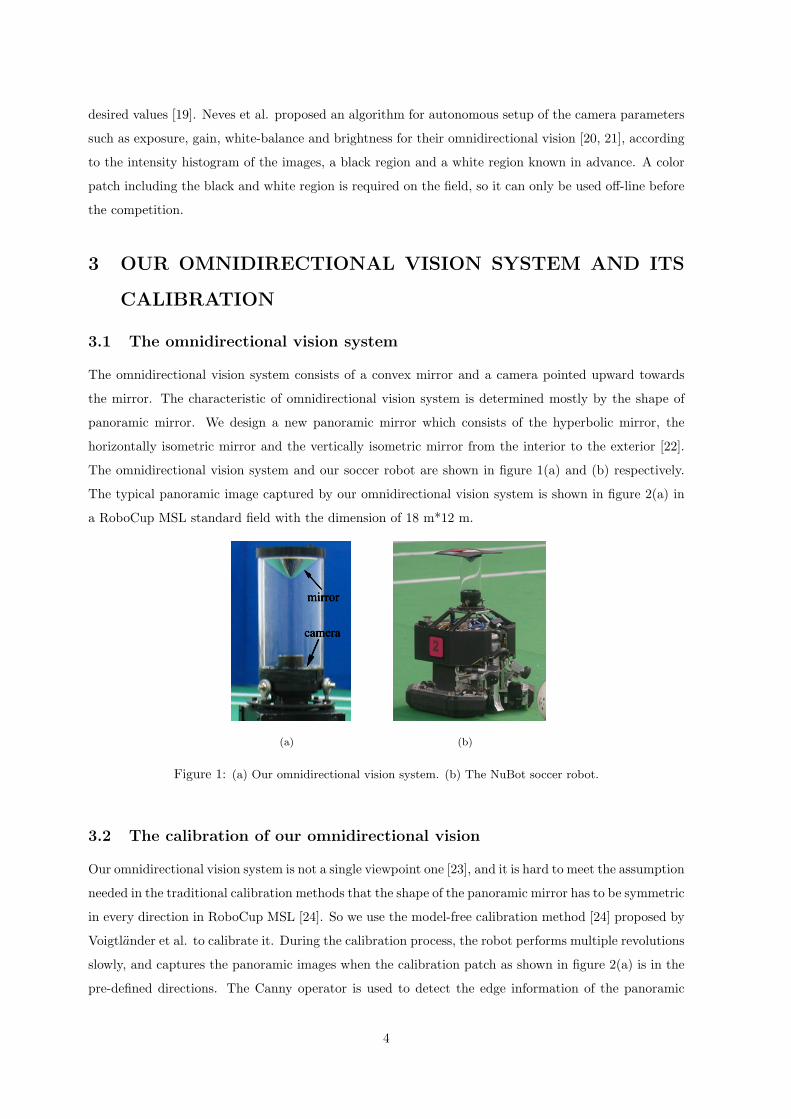
The omnidirectional vision system consists of a convex mirror and a camera pointed upward towards
the mirror. The characteristic of omnidirectional vision system is determined mostly by the shape of
panoramic mirror. We design a new panoramic mirror which consists of the hyperbolic mirror, the
horizontally isometric mirror and the vertically isometric mirror from the interior to the exterior [22].
The omnidirectional vision system and our soccer robot are shown in figure 1(a) and (b) respectively.
The typical panoramic image captured by our omnidirectional vision system is shown in figure 2(a) in
a RoboCup MSL standard field with the dimension of 18 m*12 m.
(a) (b)
Figure 1: (a) Our omnidirectional vision system. (b) The NuBot soccer robot.
3.2 The calibration of our omnidirectional vision
Our omnidirectional vision system is not a single viewpoint one [23], and it is hard to meet the assumption
needed in the traditional calibration methods that the shape of the panoramic mirror has to be symmetric
in every direction in RoboCup MSL [24]. So we use the model-free calibration method [24] proposed by
Voigtlander et al. to calibrate it. During the calibration process, the robot performs multiple revolutions
slowly, and captures the panoramic images when the calibration patch as shown in figure 2(a) is in the
pre-defined directions. The Canny operator is used to detect the edge information of the panoramic
4
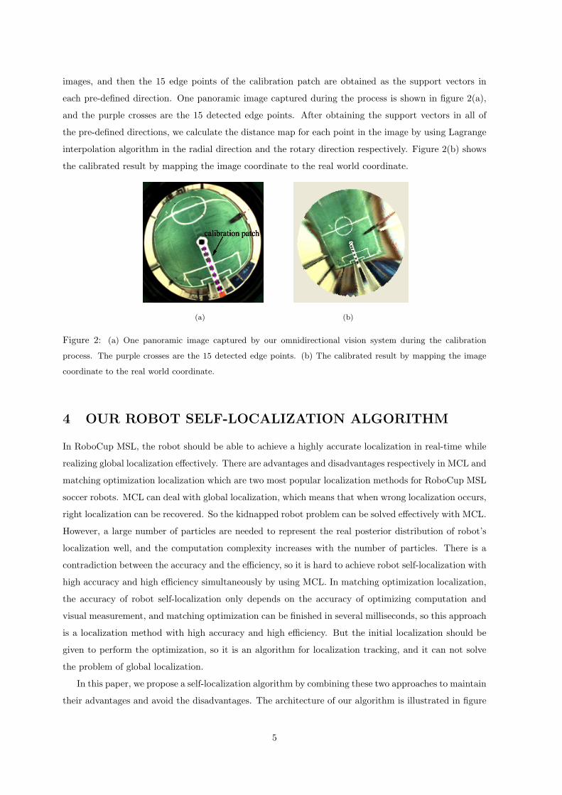
images, and then the 15 edge points of the calibration patch are obtained as the support vectors in
each pre-defined direction. One panoramic image captured during the process is shown in figure 2(a),
and the purple crosses are the 15 detected edge points. After obtaining the support vectors in all of
the pre-defined directions, we calculate the distance map for each point in the image by using Lagrange
interpolation algorithm in the radial direction and the rotary direction respectively. Figure 2(b) shows
the calibrated result by mapping the image coordinate to the real world coordinate.
(a) (b)
Figure 2: (a) One panoramic image captured by our omnidirectional vision system during the calibration
process. The purple crosses are the 15 detected edge points. (b) The calibrated result by mapping the image
coordinate to the real world coordinate.
4 OUR ROBOT SELF-LOCALIZATION ALGORITHM
In RoboCup MSL, the robot should be able to achieve a highly accurate localization in real-time while
realizing global localization effectively. There are advantages and disadvantages respectively in MCL and
matching optimization localization which are two most popular localization methods for RoboCup MSL
soccer robots. MCL can deal with global localization, which means that when wrong localization occurs,
right localization can be recovered. So the kidnapped robot problem can be solved effectively with MCL.
However, a large number of particles are needed to represent the real posterior distribution of robot’s
localization well, and the computation complexity increases with the number of particles. There is a
contradiction between the accuracy and the efficiency, so it is hard to achieve robot self-localization with
high accuracy and high efficiency simultaneously by using MCL. In matching optimization localization,
the accuracy of robot self-localization only depends on the accuracy of optimizing computation and
visual measurement, and matching optimization can be finished in several milliseconds, so this approach
is a localization method with high accuracy and high efficiency. But the initial localization should be
given to perform the optimization, so it is an algorithm for localization tracking, and it can not solve
the problem of global localization.
In this paper, we propose a self-localization algorithm by combining these two approaches to maintain
their advantages and avoid the disadvantages. The architecture of our algorithm is illustrated in figure
5
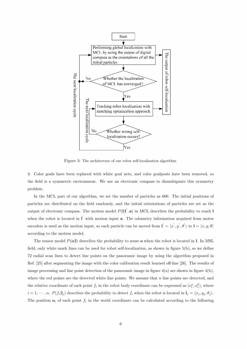
Figure 3: The architecture of our robot self-localization algorithm.
3. Color goals have been replaced with white goal nets, and color goalposts have been removed, so
the field is a symmetric environment. We use an electronic compass to disambiguate this symmetry
problem.
In the MCL part of our algorithm, we set the number of particles as 600. The initial positions of
particles are distributed on the field randomly, and the initial orientations of particles are set as the
output of electronic compass. The motion model P (l|l′ ,a) in MCL describes the probability to reach l
when the robot is located in l′with motion input a. The odometry information acquired from motor
encoders is used as the motion input, so each particle can be moved from l′= ⟨x′
, y′, θ
′⟩ to l = ⟨x, y, θ⟩
according to the motion model.
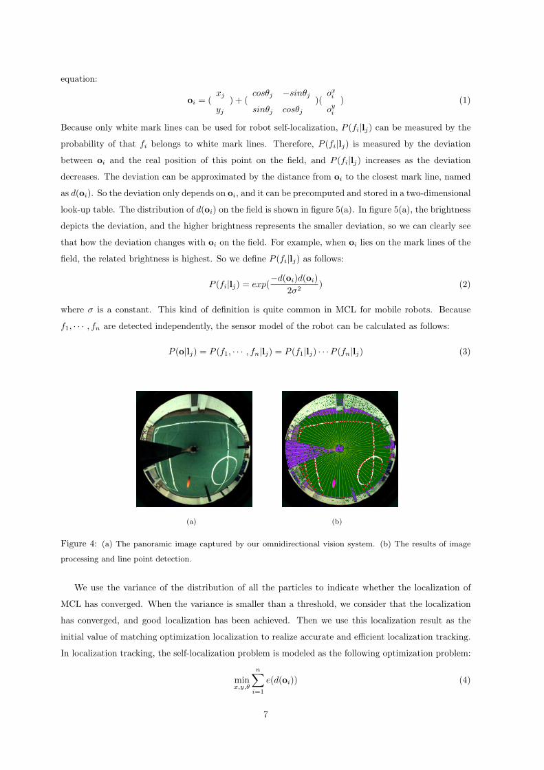
The sensor model P (o|l) describes the probability to sense o when the robot is located in l. In MSL
field, only white mark lines can be used for robot self-localization, as shown in figure 5(b), so we define
72 radial scan lines to detect line points on the panoramic image by using the algorithm proposed in
Ref. [25] after segmenting the image with the color calibration result learned off-line [26]. The results of
image processing and line point detection of the panoramic image in figure 4(a) are shown in figure 4(b),
where the red points are the detected white line points. We assume that n line points are detected, and
the relative coordinate of each point fi in the robot body coordinate can be expressed as (oxi , oyi ), where
i = 1, · · · , n. P (fi|lj) describes the probability to detect fi when the robot is located in lj = ⟨xj , yj , θj⟩.
The position oi of each point fi in the world coordinate can be calculated according to the following
6
equation:
oi = (xj
yj) + (
cosθj −sinθj
sinθj cosθj)(
oxi
oyi
) (1)
Because only white mark lines can be used for robot self-localization, P (fi|lj) can be measured by the
probability of that fi belongs to white mark lines. Therefore, P (fi|lj) is measured by the deviation
between oi and the real position of this point on the field, and P (fi|lj) increases as the deviation
decreases. The deviation can be approximated by the distance from oi to the closest mark line, named
as d(oi). So the deviation only depends on oi, and it can be precomputed and stored in a two-dimensional
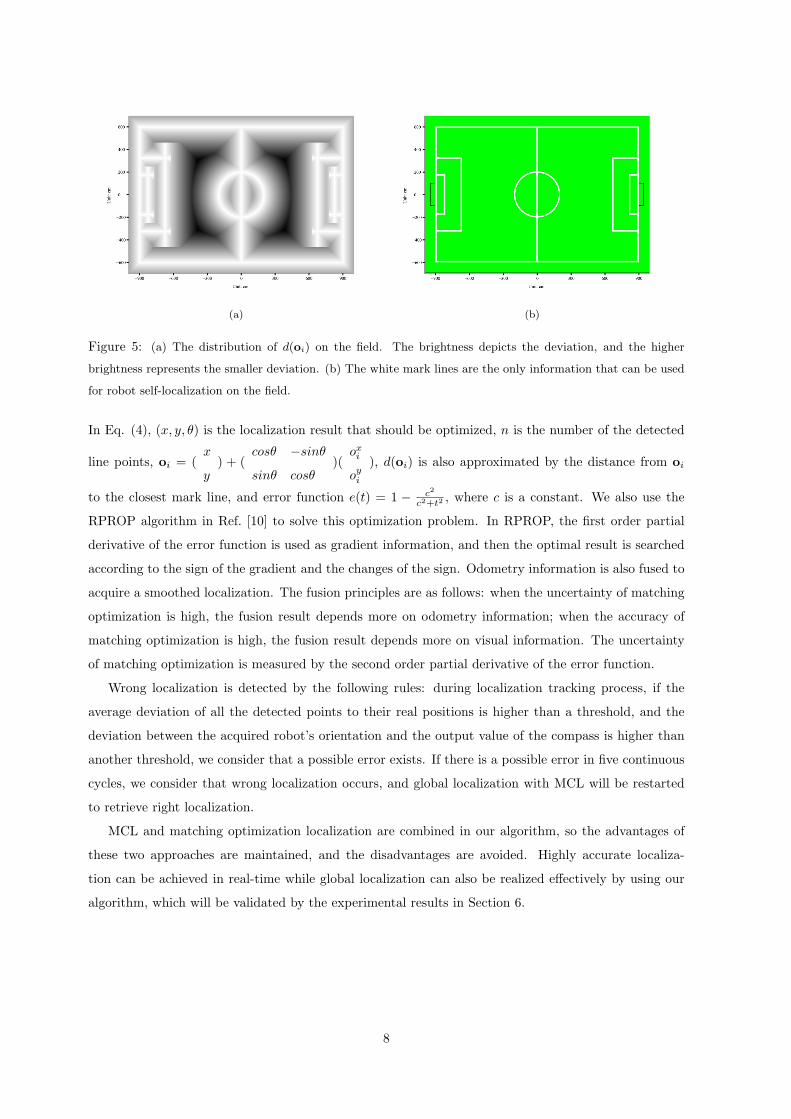
look-up table. The distribution of d(oi) on the field is shown in figure 5(a). In figure 5(a), the brightness
depicts the deviation, and the higher brightness represents the smaller deviation, so we can clearly see
that how the deviation changes with oi on the field. For example, when oi lies on the mark lines of the
field, the related brightness is highest. So we define P (fi|lj) as follows:
P (fi|lj) = exp(−d(oi)d(oi)
2σ2) (2)
where σ is a constant. This kind of definition is quite common in MCL for mobile robots. Because
f1, · · · , fn are detected independently, the sensor model of the robot can be calculated as follows:
P (o|lj) = P (f1, · · · , fn|lj) = P (f1|lj) · · ·P (fn|lj) (3)
(a) (b)
Figure 4: (a) The panoramic image captured by our omnidirectional vision system. (b) The results of image
processing and line point detection.
We use the variance of the distribution of all the particles to indicate whether the localization of
MCL has converged. When the variance is smaller than a threshold, we consider that the localization
has converged, and good localization has been achieved. Then we use this localization result as the
initial value of matching optimization localization to realize accurate and efficient localization tracking.
In localization tracking, the self-localization problem is modeled as the following optimization problem:
minx,y,θ
n∑i=1
e(d(oi)) (4)
7
(a) (b)
Figure 5: (a) The distribution of d(oi) on the field. The brightness depicts the deviation, and the higher
brightness represents the smaller deviation. (b) The white mark lines are the only information that can be used
for robot self-localization on the field.
In Eq. (4), (x, y, θ) is the localization result that should be optimized, n is the number of the detected
line points, oi = (x
y) + (
cosθ −sinθ
sinθ cosθ)(
oxi
oyi
), d(oi) is also approximated by the distance from oi
to the closest mark line, and error function e(t) = 1 − c2
c2+t2 , where c is a constant. We also use the
RPROP algorithm in Ref. [10] to solve this optimization problem. In RPROP, the first order partial
derivative of the error function is used as gradient information, and then the optimal result is searched
according to the sign of the gradient and the changes of the sign. Odometry information is also fused to
acquire a smoothed localization. The fusion principles are as follows: when the uncertainty of matching
optimization is high, the fusion result depends more on odometry information; when the accuracy of
matching optimization is high, the fusion result depends more on visual information. The uncertainty
of matching optimization is measured by the second order partial derivative of the error function.
Wrong localization is detected by the following rules: during localization tracking process, if the
average deviation of all the detected points to their real positions is higher than a threshold, and the
deviation between the acquired robot’s orientation and the output value of the compass is higher than
another threshold, we consider that a possible error exists. If there is a possible error in five continuous
cycles, we consider that wrong localization occurs, and global localization with MCL will be restarted
to retrieve right localization.
MCL and matching optimization localization are combined in our algorithm, so the advantages of
these two approaches are maintained, and the disadvantages are avoided. Highly accurate localiza-
tion can be achieved in real-time while global localization can also be realized effectively by using our
algorithm, which will be validated by the experimental results in Section 6.
8
5 INTEGRATING CAMERA PARAMETERS AUTO-ADJUSTING
ALGORITHM BASED ON IMAGE ENTROPY
In the current MSL competition, more and more natural light have been added into the field, which
brings challenges to robot’s vision system and visual localization. In Ref. [27, 28], we proposed a
novel method to auto-adjust camera parameters based on image entropy to achieve the robustness and
adaptability of the camera’s output with respect to different lighting conditions.
First, we use Shannon’s entropy to define image entropy as follows:
Entropy = −L−1∑Ri=0
PRi logPRi −L−1∑Gi=0
PGi logPGi −L−1∑Bi=0
PBi logPBi (5)
where L = 256 is the number of discrete levels of RGB color channels, and PRi,PGi,PBi are the probabili-
ty of color value Ri,Gi,Bi existing in the three color channels of the image. The probability PRi,PGi,PBi
can be replaced with the frequency approximately, so they are calculated according to the three his-
togram distributions of the image in RGB color channels.
In the camera of our omnidirectional vision, only exposure time and gain are able to be adjusted
(auto white-balance has been achieved in the camera, so we do not consider white-balance). We captured
a series of panoramic images by using our omnidirectional vision system with different exposure time
and gain in a standard MSL field, and calculated image entropy according to Eq. (5) to see how image
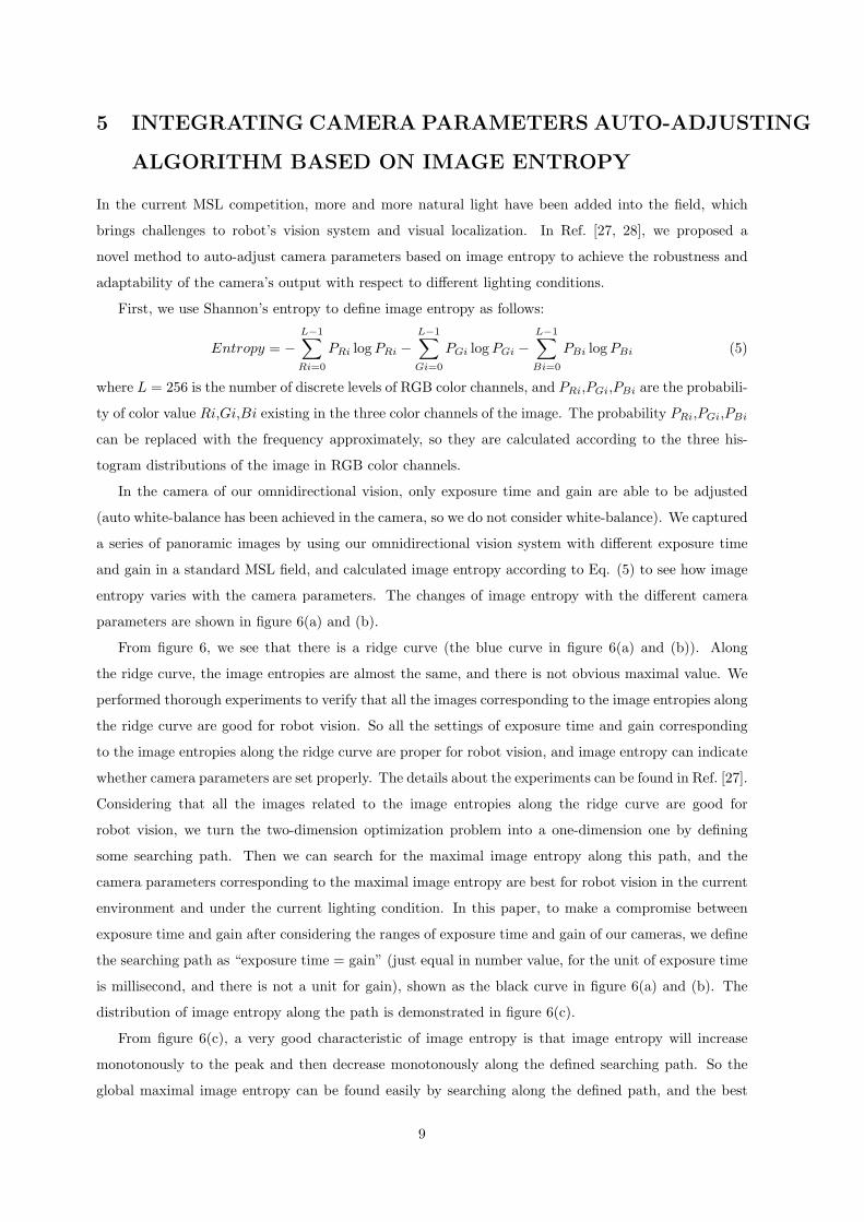
entropy varies with the camera parameters. The changes of image entropy with the different camera
parameters are shown in figure 6(a) and (b).
From figure 6, we see that there is a ridge curve (the blue curve in figure 6(a) and (b)). Along
the ridge curve, the image entropies are almost the same, and there is not obvious maximal value. We
performed thorough experiments to verify that all the images corresponding to the image entropies along
the ridge curve are good for robot vision. So all the settings of exposure time and gain corresponding
to the image entropies along the ridge curve are proper for robot vision, and image entropy can indicate
whether camera parameters are set properly. The details about the experiments can be found in Ref. [27].
Considering that all the images related to the image entropies along the ridge curve are good for
robot vision, we turn the two-dimension optimization problem into a one-dimension one by defining
some searching path. Then we can search for the maximal image entropy along this path, and the
camera parameters corresponding to the maximal image entropy are best for robot vision in the current
environment and under the current lighting condition. In this paper, to make a compromise between
exposure time and gain after considering the ranges of exposure time and gain of our cameras, we define
the searching path as “exposure time = gain” (just equal in number value, for the unit of exposure time
is millisecond, and there is not a unit for gain), shown as the black curve in figure 6(a) and (b). The
distribution of image entropy along the path is demonstrated in figure 6(c).
From figure 6(c), a very good characteristic of image entropy is that image entropy will increase
monotonously to the peak and then decrease monotonously along the defined searching path. So the
global maximal image entropy can be found easily by searching along the defined path, and the best
9
0
20
40
0510152025
0
2
4
6
8
10
12
14
16
GainExposure time(ms)
Imag
e E
ntro
py
(a)
010
2030
40 010
20300
2
4
6
8
10
12
14
16
GainExposure time(ms)
Imag
e E
ntro
py
(b)
4 6 8 10 12 14 16 18 20 220
5
10
15
the Exposure time(ms) or the Gain (two values are equal to each other)
Ent
ropy
(c)
Figure 6: The change of image entropy with different exposure time and gain. (a) and (b) are the same result
viewed from two different view angles. (c) The distribution of image entropy along the defined searching path
“exposure time=gain”.
camera parameters are determined at the same time. In figure 6(c), the best exposure time and gain
are 18 ms and 18 respectively.
Actually, the searching path should be changed according to different camera characteristics, and
the different requirements of the vision system in different applications. For example, the value range
of gain depends on the camera used. Some range is from 0 to 50, and others may be from 0 to 4000. So
the searching path should be “exposure time=a*gain+b” (also just equal in number value), where the
variable a and b can be determined manually after analyzing the gain’s effect on the images. For the
cameras with similar parameter ranges as ours, if the signal to noise ratio of the image is required to be
high and the real-time performance is not necessary, the searching path can be “exposure time=α*gain”,
with α > 1.
According to the special characteristic of omnidirectional vision, the robot itself is imaged in the
central region of the panoramic image all the time. Therefore in actual applications, the robot can
judge that whether it has entered into a totally new environment or if the illumination has changed in
the current environment by calculating the mean brightness value in the central part of the panoramic
image. If the increase of the mean value is higher than a certain threshold, the illumination becomes
10
stronger, and the optimization of camera parameters should be run in the direction that exposure time
and gain reduce along the searching path. Similarly, if the decrease of the mean value is higher than
the threshold, the optimization should be run in the direction that exposure time and gain raise along
the searching path. The mean value will not be considered during the optimizing process, and it is
not needed either. After the optimal camera parameters have been achieved, it will be calculated and
saved again, and it will be compared with the new ones to judge whether the adjustment of the camera
parameters is needed. Of course, this judgement can be scheduled to perform only once every several
cycles, because the changes in illumination are not that rapid.
When the robot is in different positions on the field, the acquired images will be different, so the
maximal image entropy along the searching path varies with the different locations of the robot. There-
fore, once the robot finds that camera parameters auto-adjustment is needed, it should stop at the same
place till the optimization is finished. In the optimizing process, a new group of parameters are set
into the camera, and then a new image is acquired and image entropy can be calculated according to
Eq. (5). The new entropy is then compared with the last one to check whether the maximal entropy
has been reached. This iteration continues until the maximal entropy has been reached, so the best
camera parameters are acquired under the current lighting condition for our omnidirectional vision.
After integrating this camera parameters auto-adjusting algorithm, robot self-localization can be robust
to changing lighting conditions, which will be validated by the experimental results in Section 6.3.
6 THE EXPERIMENTAL RESULTS
In this section, we perform three groups of robot self-localization experiments on a standard MSL field
to evaluate our algorithm proposed in the above two sections. During the experimental process, the
robot was pushed by people to follow some straight tracks on the field shown as the black lines in figure
8. The red traces depict the robot self-localization results.
6.1 The self-localization with occlusion
During the competition, the robot’s vision system is always occluded partially by teammates or oppo-
nents. So in this experiment, we tested the robustness of our algorithm to the occlusion of omnidirec-
tional vision. We simulated the occlusion by adding black stripes and not processing these image regions.
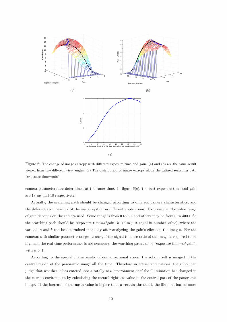
We assume that omnidirectional vision is occluded 12.5%, 25%, and 50% respectively. The results of
image processing and line point detection of the panoramic image in figure 4(a) are shown in figure 7,
where black sectors are the occluded areas. The self-localization results without any occlusion and with
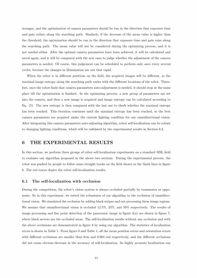
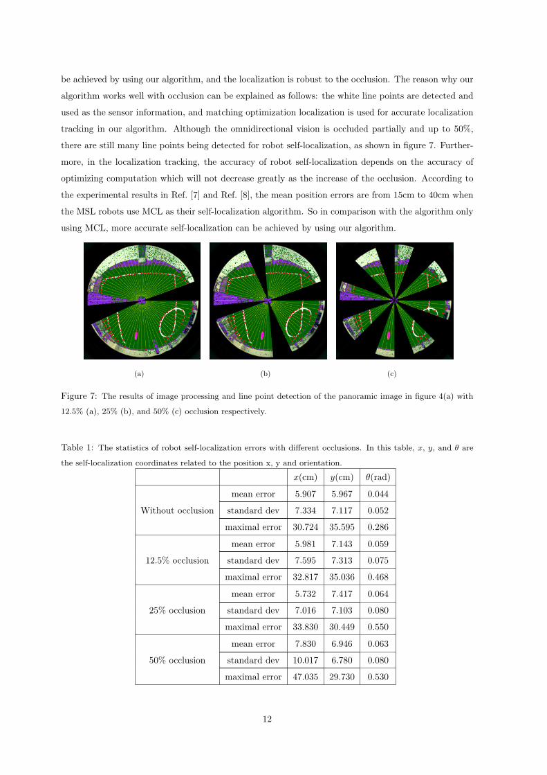
the above occlusions are demonstrated in figure 8 by using our algorithm. The statistics of localization
errors is shown in Table 1. From figure 8 and Table 1, all the mean position errors and orientation errors
with different occlusions are smaller than 8cm and 0.064 rad respectively, and the different occlusions
did not cause obvious decrease in the accuracy of self-localization. So highly accurate localization can
11
be achieved by using our algorithm, and the localization is robust to the occlusion. The reason why our
algorithm works well with occlusion can be explained as follows: the white line points are detected and
used as the sensor information, and matching optimization localization is used for accurate localization
tracking in our algorithm. Although the omnidirectional vision is occluded partially and up to 50%,
there are still many line points being detected for robot self-localization, as shown in figure 7. Further-
more, in the localization tracking, the accuracy of robot self-localization depends on the accuracy of
optimizing computation which will not decrease greatly as the increase of the occlusion. According to
the experimental results in Ref. [7] and Ref. [8], the mean position errors are from 15cm to 40cm when
the MSL robots use MCL as their self-localization algorithm. So in comparison with the algorithm only
using MCL, more accurate self-localization can be achieved by using our algorithm.
(a) (b) (c)
Figure 7: The results of image processing and line point detection of the panoramic image in figure 4(a) with
12.5% (a), 25% (b), and 50% (c) occlusion respectively.
Table 1: The statistics of robot self-localization errors with different occlusions. In this table, x, y, and θ are
the self-localization coordinates related to the position x, y and orientation.
x(cm) y(cm) θ(rad)
mean error 5.907 5.967 0.044
Without occlusion standard dev 7.334 7.117 0.052
maximal error 30.724 35.595 0.286
mean error 5.981 7.143 0.059
12.5% occlusion standard dev 7.595 7.313 0.075
maximal error 32.817 35.036 0.468
mean error 5.732 7.417 0.064
25% occlusion standard dev 7.016 7.103 0.080
maximal error 33.830 30.449 0.550
mean error 7.830 6.946 0.063
50% occlusion standard dev 10.017 6.780 0.080
maximal error 47.035 29.730 0.530
12
(a) (b)
(c) (d)
(e) (f)
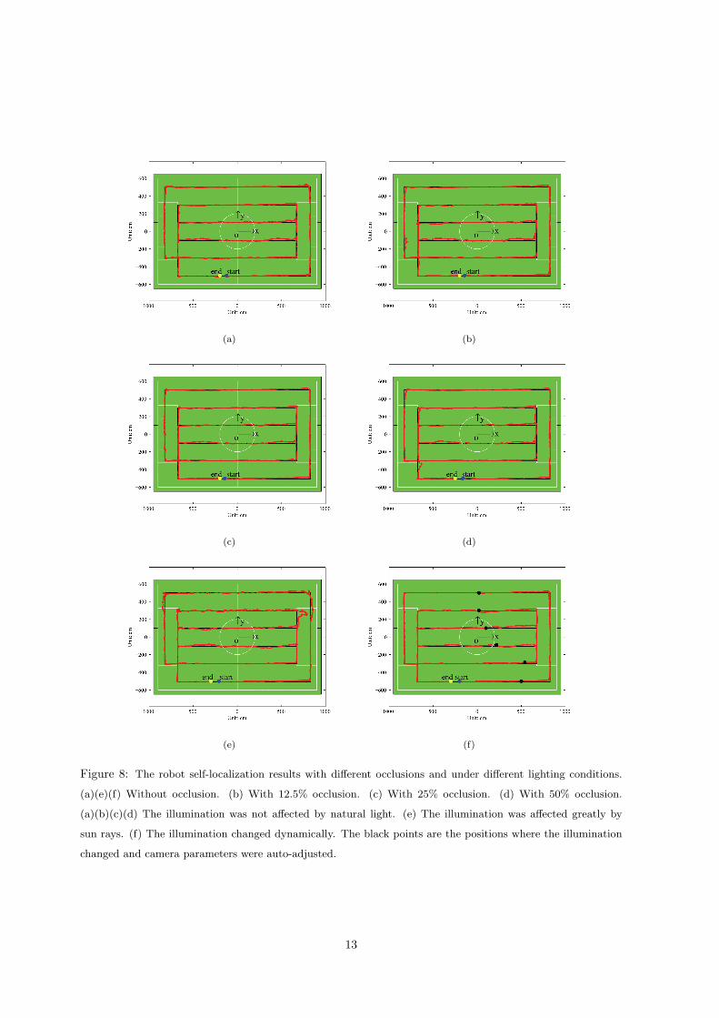
Figure 8: The robot self-localization results with different occlusions and under different lighting conditions.
(a)(e)(f) Without occlusion. (b) With 12.5% occlusion. (c) With 25% occlusion. (d) With 50% occlusion.
(a)(b)(c)(d) The illumination was not affected by natural light. (e) The illumination was affected greatly by
sun rays. (f) The illumination changed dynamically. The black points are the positions where the illumination
changed and camera parameters were auto-adjusted.
13
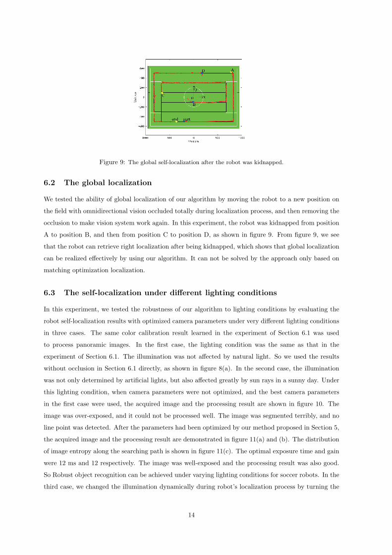
Figure 9: The global self-localization after the robot was kidnapped.
6.2 The global localization
We tested the ability of global localization of our algorithm by moving the robot to a new position on
the field with omnidirectional vision occluded totally during localization process, and then removing the
occlusion to make vision system work again. In this experiment, the robot was kidnapped from position
A to position B, and then from position C to position D, as shown in figure 9. From figure 9, we see
that the robot can retrieve right localization after being kidnapped, which shows that global localization
can be realized effectively by using our algorithm. It can not be solved by the approach only based on
matching optimization localization.
6.3 The self-localization under different lighting conditions
In this experiment, we tested the robustness of our algorithm to lighting conditions by evaluating the
robot self-localization results with optimized camera parameters under very different lighting conditions
in three cases. The same color calibration result learned in the experiment of Section 6.1 was used
to process panoramic images. In the first case, the lighting condition was the same as that in the
experiment of Section 6.1. The illumination was not affected by natural light. So we used the results
without occlusion in Section 6.1 directly, as shown in figure 8(a). In the second case, the illumination
was not only determined by artificial lights, but also affected greatly by sun rays in a sunny day. Under
this lighting condition, when camera parameters were not optimized, and the best camera parameters
in the first case were used, the acquired image and the processing result are shown in figure 10. The
image was over-exposed, and it could not be processed well. The image was segmented terribly, and no
line point was detected. After the parameters had been optimized by our method proposed in Section 5,
the acquired image and the processing result are demonstrated in figure 11(a) and (b). The distribution
of image entropy along the searching path is shown in figure 11(c). The optimal exposure time and gain
were 12 ms and 12 respectively. The image was well-exposed and the processing result was also good.
So Robust object recognition can be achieved under varying lighting conditions for soccer robots. In the
third case, we changed the illumination dynamically during robot’s localization process by turning the
14
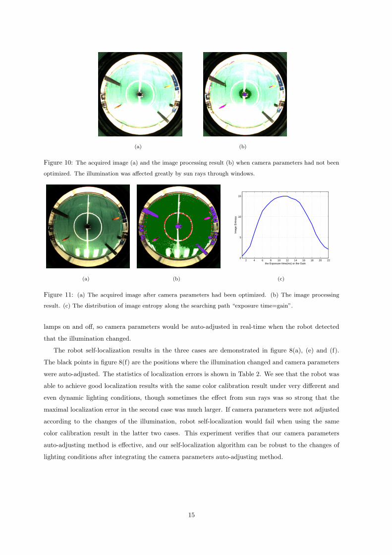
(a) (b)
Figure 10: The acquired image (a) and the image processing result (b) when camera parameters had not been
optimized. The illumination was affected greatly by sun rays through windows.
(a) (b)
2 4 6 8 10 12 14 16 18 20 220
5
10
15
the Exposure time(ms) or the Gain
Imag
e E
ntro
py
(c)
Figure 11: (a) The acquired image after camera parameters had been optimized. (b) The image processing
result. (c) The distribution of image entropy along the searching path “exposure time=gain”.
lamps on and off, so camera parameters would be auto-adjusted in real-time when the robot detected
that the illumination changed.
The robot self-localization results in the three cases are demonstrated in figure 8(a), (e) and (f).
The black points in figure 8(f) are the positions where the illumination changed and camera parameters
were auto-adjusted. The statistics of localization errors is shown in Table 2. We see that the robot was
able to achieve good localization results with the same color calibration result under very different and
even dynamic lighting conditions, though sometimes the effect from sun rays was so strong that the
maximal localization error in the second case was much larger. If camera parameters were not adjusted
according to the changes of the illumination, robot self-localization would fail when using the same
color calibration result in the latter two cases. This experiment verifies that our camera parameters
auto-adjusting method is effective, and our self-localization algorithm can be robust to the changes of
lighting conditions after integrating the camera parameters auto-adjusting method.
15
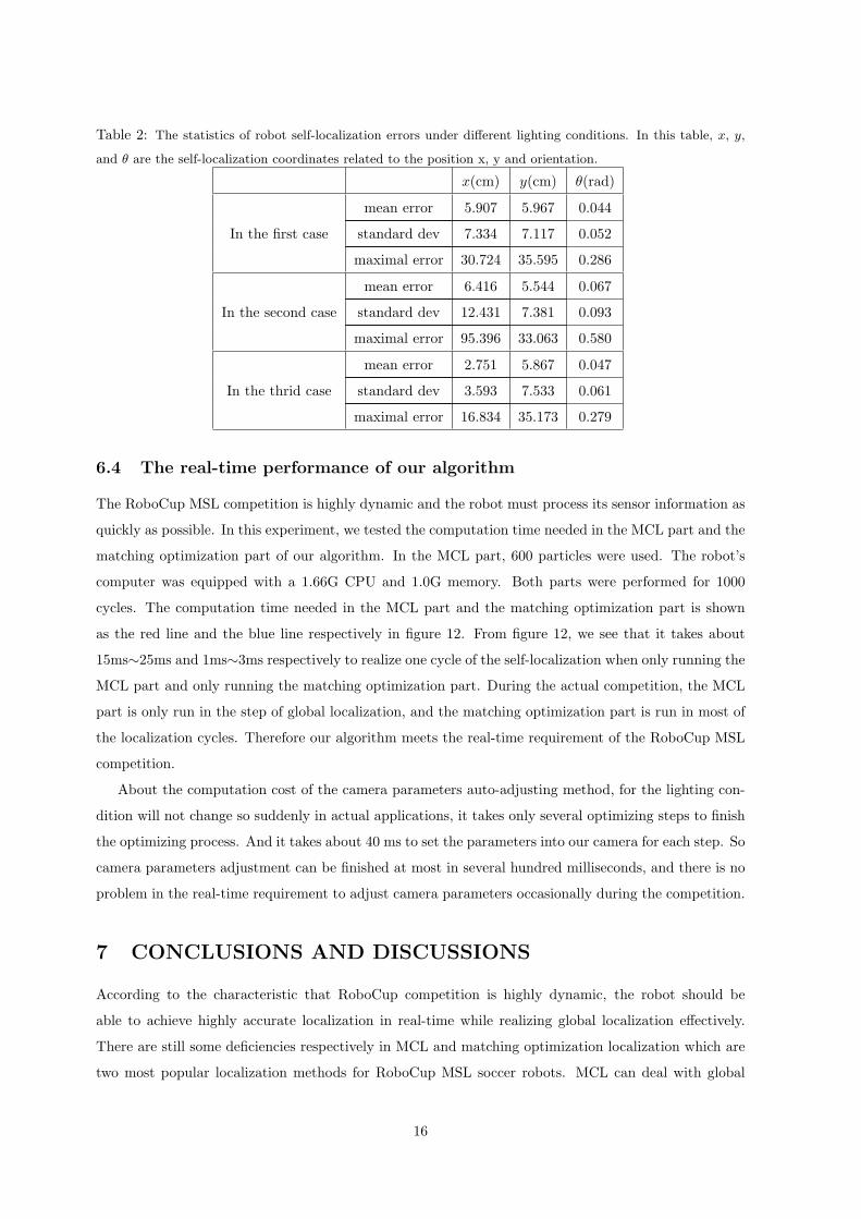
Table 2: The statistics of robot self-localization errors under different lighting conditions. In this table, x, y,
and θ are the self-localization coordinates related to the position x, y and orientation.
x(cm) y(cm) θ(rad)
mean error 5.907 5.967 0.044
In the first case standard dev 7.334 7.117 0.052
maximal error 30.724 35.595 0.286
mean error 6.416 5.544 0.067
In the second case standard dev 12.431 7.381 0.093
maximal error 95.396 33.063 0.580
mean error 2.751 5.867 0.047
In the thrid case standard dev 3.593 7.533 0.061
maximal error 16.834 35.173 0.279
6.4 The real-time performance of our algorithm
The RoboCup MSL competition is highly dynamic and the robot must process its sensor information as
quickly as possible. In this experiment, we tested the computation time needed in the MCL part and the
matching optimization part of our algorithm. In the MCL part, 600 particles were used. The robot’s
computer was equipped with a 1.66G CPU and 1.0G memory. Both parts were performed for 1000
cycles. The computation time needed in the MCL part and the matching optimization part is shown
as the red line and the blue line respectively in figure 12. From figure 12, we see that it takes about
15ms∼25ms and 1ms∼3ms respectively to realize one cycle of the self-localization when only running the
MCL part and only running the matching optimization part. During the actual competition, the MCL
part is only run in the step of global localization, and the matching optimization part is run in most of
the localization cycles. Therefore our algorithm meets the real-time requirement of the RoboCup MSL
competition.
About the computation cost of the camera parameters auto-adjusting method, for the lighting con-
dition will not change so suddenly in actual applications, it takes only several optimizing steps to finish
the optimizing process. And it takes about 40 ms to set the parameters into our camera for each step. So
camera parameters adjustment can be finished at most in several hundred milliseconds, and there is no
problem in the real-time requirement to adjust camera parameters occasionally during the competition.
7 CONCLUSIONS AND DISCUSSIONS
According to the characteristic that RoboCup competition is highly dynamic, the robot should be
able to achieve highly accurate localization in real-time while realizing global localization effectively.
There are still some deficiencies respectively in MCL and matching optimization localization which are
two most popular localization methods for RoboCup MSL soccer robots. MCL can deal with global
16
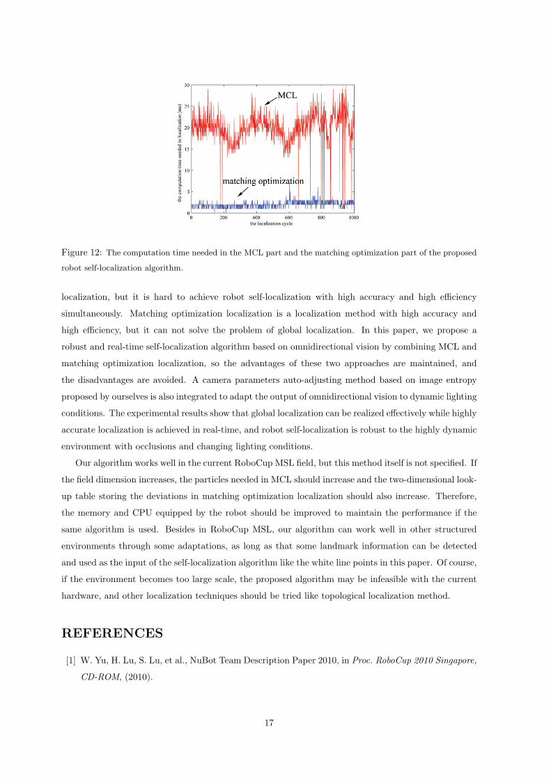
Figure 12: The computation time needed in the MCL part and the matching optimization part of the proposed
robot self-localization algorithm.
localization, but it is hard to achieve robot self-localization with high accuracy and high efficiency
simultaneously. Matching optimization localization is a localization method with high accuracy and
high efficiency, but it can not solve the problem of global localization. In this paper, we propose a
robust and real-time self-localization algorithm based on omnidirectional vision by combining MCL and
matching optimization localization, so the advantages of these two approaches are maintained, and
the disadvantages are avoided. A camera parameters auto-adjusting method based on image entropy
proposed by ourselves is also integrated to adapt the output of omnidirectional vision to dynamic lighting
conditions. The experimental results show that global localization can be realized effectively while highly
accurate localization is achieved in real-time, and robot self-localization is robust to the highly dynamic
environment with occlusions and changing lighting conditions.
Our algorithm works well in the current RoboCup MSL field, but this method itself is not specified. If
the field dimension increases, the particles needed in MCL should increase and the two-dimensional look-
up table storing the deviations in matching optimization localization should also increase. Therefore,
the memory and CPU equipped by the robot should be improved to maintain the performance if the
same algorithm is used. Besides in RoboCup MSL, our algorithm can work well in other structured
environments through some adaptations, as long as that some landmark information can be detected
and used as the input of the self-localization algorithm like the white line points in this paper. Of course,
if the environment becomes too large scale, the proposed algorithm may be infeasible with the current
hardware, and other localization techniques should be tried like topological localization method.
REFERENCES
[1] W. Yu, H. Lu, S. Lu, et al., NuBot Team Description Paper 2010, in Proc. RoboCup 2010 Singapore,
CD-ROM, (2010).
17
[2] M. Betke and L. Gurvits, Mobile Robot Localization Using Landmarks. IEEE Transactions on
Robotics and Automation, 13, 251-263 (1997).
[3] G. Adorni, S. Cagnoni, S. Enderle, et al., Vision-based localization for mobile robots. Robotics and
Autonomous Systems, 36, 103-119 (2001).
[4] A. Motomura, T. Matsuoka, and T. Hasegawa, Self-Localization Method Using Two Landmarks
and Dead Reckoning for Autonomous Mobile Soccer Robots, in RoboCup 2003: Robot Soccer World
Cup VII, pp. 526-533, Springer-Verlag (2004).
[5] P. Lima, A. Bonarini, C. Machado, et al., Omni-directional catadioptric vision for soccer robots.
Robotics and Autonomous Systems, 36, 87-102 (2001).
[6] E. Menegatti, A. Pretto, A. Scarpa, E. Pagello, Omnidirectional Vision Scan Matching for Robot
Localization in Dynamic Environments. IEEE Transactions on Robotics, 22, 523-535 (2006).
[7] A. Merke, S. Welker, and M. Riedmiller, Line based robot localization under natural light condi-
tions, in Proc. ECAI 2004 Workshop on Agents in Dynamic and Real Time Environments, (2004).
[8] P. Heinemann, J. Haase, and A. Zell, A Novel Approach to Efficient Monte-Carlo Localization in
RoboCup, in RoboCup 2006: Robot Soccer World Cup X, pp.322-329, Springer-Verlag (2007).
[9] P. Heinemann, J. Haase, and A. Zell, A Combined Monte-Carlo Localization and Tracking Algo-
rithm for RoboCup, in Proc. the 2006 IEEE/RSJ International Conference on Intelligent Robots
and Systems, pp.1535-1540 (2006).
[10] M. Lauer, S. Lange, and M. Riedmiller, Calculating the perfect match: An efficient and accurate
approach for robot self-localization, in RoboCup 2005: Robot Soccer World Cup IX, pp.142-153,
Springer-Verlag (2006).
[11] J. Silva, N. Lau, A.J.R. Neves, et al., World modeling on an MSL robotic soccer team.Mechatronics,
21, 411-422 (2011).
[12] D. Fox, Adapting the sample size in particle filters through KLD-sampling. International Journal
of Robotics Research, 22, 985-1003 (2003).
[13] C. Gamallo, C.V. Regueiro, P. Quintia, and M. Mucientes, Omnivision-based KLD-Monte Carlo
Localization. Robotics and Autonomous Systems, 58, 295-305 (2010).
[14] C. Gonner, M. Rous, and K. Kraiss, Real-Time Adaptive Colour Segmentation for the RoboCup
Middle Size League, in RoboCup 2004: Robot Soccer World Cup VIII, pp.402-409, Springer-Verlag
(2005).
[15] F. Anzani, D. Bosisio, M. Matteucci, and D.G. Sorrenti, On-Line Color Calibration in Non-
Stationary Environments, in RoboCup 2005: Robot Soccer World Cup IX, pp.396-407, Springer-
Verlag (2006).
18
[16] P. Heinemann, F. Sehnke, F. Streichert, and A. Zell, Towards a Calibration-Free Robot: The ACT
Algorithm for Automatic Online Color Training, in RoboCup 2006: Robot Soccer World Cup X,
pp.363-370, Springer-Verlag (2007).
[17] E. Grillo, M. Matteucci, and D.G. Sorrenti, Getting the most from your color camera in a color-
coded world, in RoboCup 2004: Robot Soccer World Cup VIII, pp.221-235, Springer-Verlag (2005).
[18] Y. Takahashi, W. Nowak, and T. Wisspeintner, Adaptive Recognition of Color-Coded Objects
in Indoor and Outdoor Environments, in RoboCup 2007: Robot Soccer World Cup XI, pp.65-76,
Springer-Verlag (2008).
[19] J.J.M. Lunenburg and G.v.d. Ven, Tech United Team Description, in Proc. RoboCup 2008 Suzhou,
CD-ROM, (2008).
[20] A.J.R. Neves, B. Cunha, A.J. Pinho, and I. Pinheiro, Aotonomous configuration of parameters in
robotic digital cameras, in IbPRIA 2009, LNCS 5524, pp.80-87, Springer-Verlag (2009).
[21] A.J.R. Neves, A.J. Pinho, D.A. Martins, and B. Cunha, An efficient omnidirectional vision system
for soccer robots: From calibration to object detection. Mechatronics, 21, 399-410 (2011).
[22] H. Lu, H. Zhang, J. Xiao, et al., Arbitrary ball recognition based on omnidirectional vision for
soccer robots, in RoboCup 2008: Robot Soccer World Cup XII, pp.133-144, Springer-Verlag (2009).
[23] R. Benosman and S.B. Kang, editors, Panoramic Vision: Sensors, Theory and Applications,
Springer-Verlag (2001).
[24] A. Voigtlander, S. Lange, M. Lauer, and M. Riedmiller, Real-time 3D ball recognition using per-
spective and catadioptric cameras, in Proc. 2007 European Conference on Mobile Robots, (2007).
[25] H. Lu, Z. Zheng, F. Liu, and X. Wang, A Robust Object Recognition Method for Soccer Robots,
in Proc. the 7th World Congress on Intelligent Control and Automation, pp.1645-1650 (2008).
[26] F. Liu, H. Lu, and Z. Zheng, A modified color look-up table segmentation method for robot soccer,
in Proc. the 4th IEEE LARS/COMRob 07, (2007).
[27] H. Lu, S. Yang, H. Zhang, and Z. Zheng, A robust omnidirectional vision sensor for soccer robots.
Mechatronics, 21, 373-389 (2011).
[28] H. Lu, H. Zhang, S. Yang, and Z. Zheng, Camera Parameters Auto-Adjusting Technique for Robust
Robot Vision, in Proc. 2010 IEEE International Conference on Robotics and Automation, pp.1518-
1523 (2010).
19