robobuilder user (published version)
TRANSCRIPT
0
Microsoft Robotics Developer Studio(MSRDS) Visual Programming Language(VPL) for
ROBOBUILDER USER (Published Version)
ROBOBUILDER CO., LTD.
1
TABLE OF CONTENTS
11.. WWhhaatt iiss RRoobboott?? .............................................................................................................................................................................................................................................. 55
11..11 RRoobboott ............................................................................................................................. 5 11..22 OOrriiggiinn ooff RRoobboott .............................................................................................................. 7 11..33 HHiissttoorryy ooff IInntteelllliiggeenntt RRoobboott .......................................................................................... 10 11..44 IInntteelllliiggeenntt RRoobboott SSttrruuccttuurree ........................................................................................... 12
22.. RRoobbooBBuuiillddeerr IInnttrroodduuccttiioonn ........................................................................................................................................................................................................2211
22..11 OOvveerrvviieeww ...................................................................................................................... 21 22..22 RRoobbooBBuuiillddeerr SSppeecciiffiiccaattiioonn aanndd PPaarrtt LLiisstt ...................................................................... 25
33.. MMiiccrroossoofftt RRoobboottiiccss SSttuuddiioo((MMSSRRDDSS)) ......................................................................................................................................................................3344
33..11 OOvveerrvviieeww ...................................................................................................................... 34 33..22 MMSSRRDDSS BBaacckkggrroouunndd ................................................................................................... 35 33..33 MMSSRRDDSS AApppplliiccaattiioonn .................................................................................................. 36
44.. HHaarrddwwaarree SSeettuupp ........................................................................................................................................................................................................................................3388
44..11 PPoowweerr SSuuppppllyy .............................................................................................................. 38 44..22 HHooww TToo CChhaarrggee ............................................................................................................ 39 44..33 CCoommmmuunniiccaattiioonn wwiitthh PPCC .............................................................................................. 40
55.. SSooffttwwaarree DDoowwnnllooaadd aanndd IInnssttaallllaattiioonn ....................................................................................................................................................................4422
55..11 RRoobbooBBuuiillddeerr SSooffttwwaarree.................................................................................................. 42 55..22 MMSSRRDDSS SSooffttwwaarree ........................................................................................................ 70
66.. MMSSRRDDSS -- VVPPLL DDeevveellooppmmeenntt EEnnvviirroonnmmeenntt ..................................................................................................................................................7755
66..11 OOvveerrvviieeww ...................................................................................................................... 75 66..22 VVPPLL DDeevveellooppmmeenntt EEnnvviirroonnmmeenntt .................................................................................. 77 66..33 SSttrruuccttuurree aanndd FFuunnccttiioonn ................................................................................................ 83
77.. VVPPLL -- BBaassiicc AAccttiivviittiieess ......................................................................................................................................................................................................................8866
77..11 DDaattaa AAccttiivviittyy ................................................................................................................. 86 77..22 VVaarriiaabbllee AAccttiivviittyy ........................................................................................................... 89 77..33 CCaallccuullaattee AAccttiivviittyy ......................................................................................................... 93 77..44 JJooiinn AAccttiivviittyy ................................................................................................................ 100 77..66 Switch AAccttiivviittyy ............................................................................................................ 107 77..77 Merge AAccttiivviittyy ............................................................................................................ 108 77..88 LLiisstt aanndd LLiisstt FFuunnccttiioonnss AAccttiivviittyy .................................................................................. 109 77..99 AAccttiivviittyy AAccttiivviittyy ........................................................................................................... 122 77..1100 CCoommmmeenntt AAccttiivviittyy ....................................................................................................... 134
88.. MMSSRRDDSS--VVPPLL SSeerrvviiccee PPrrooggrraammmmiinngg ....................................................................................................................................................................113344
88..11 SSeerrvviiccee CCoonnffiigguurraattiioonn ................................................................................................ 135 88..22 UUttiilliittyy sseerrvviiccee ............................................................................................................. 139
99.. MMSSRRDDSS--VVPPLL PPrrooggrraammmmiinngg wwiitthh RRoobbooBBuuiillddeerr ..................................................................................................................................................116633
99..11 PPllaayy MMoottiioonn aanndd SSoouunndd ............................................................................................. 163 99..22 IInntteerrffaaccee SSeerrvviiccee ........................................................................................................ 167 99..33 XX BBooxx CCoonnttrroolllleerr SSeerrvviiccee ........................................................................................... 172 99..44 WWeebb CCaamm SSeerrvviiccee ...................................................................................................... 184 99..55 SSppeeeecchh RReeccooggnniizzeerr SSeerrvviiccee ...................................................................................... 191 1100..11 PPllaayy CCoonnttiinnuuoouuss MMoottiioonn ............................................................................................ 196
1100.. AAppppeennddiixx ..........................................................................................................................................................................................................................................................220055
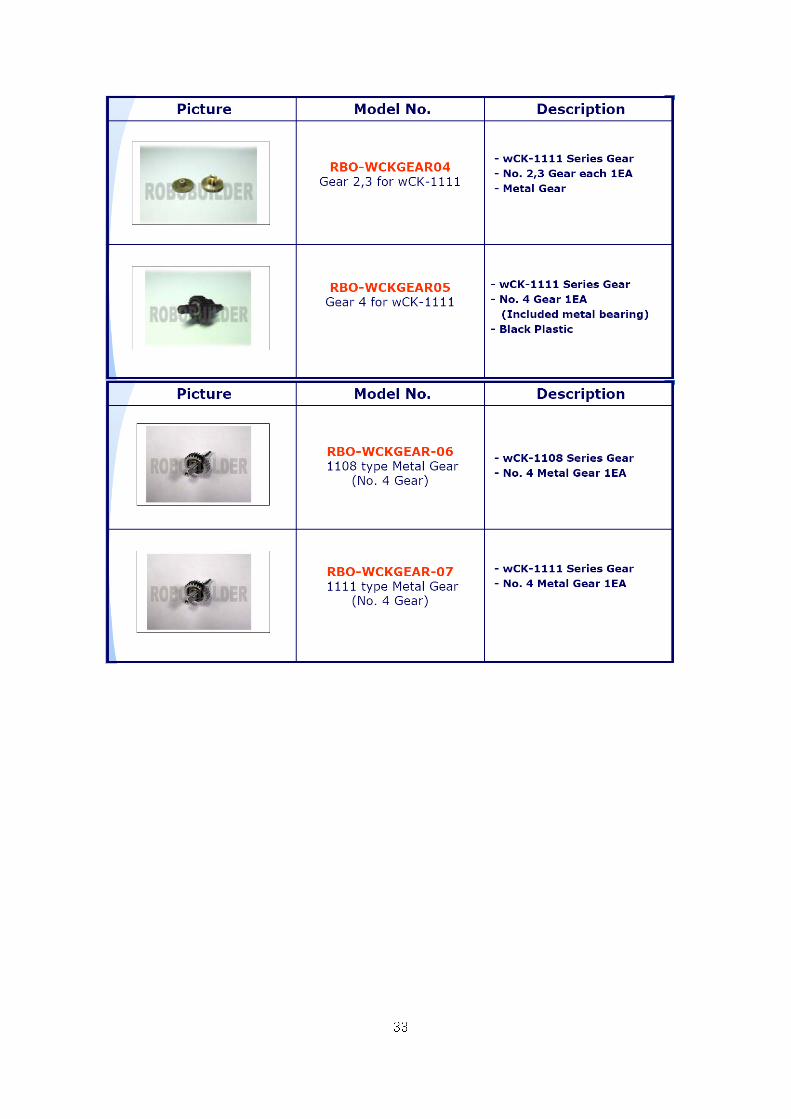
11.1 How To Replace the Damaged wCK Gear ................................................................ 205 11.2 How To Change the wCK module ID ......................................................................... 206 11.3 How To Change with Various HUNO Arm Type ......................................................... 210 11.4 RoboBuilder Remote Control Command ................................................................... 213 11.5 RoboBuilder Motion and Sound List .......................................................................... 214
2
Introduction
Microsoft has showed interest in Robot field and released Robot programming language
and platform environment. MSRDS (Microsoft Robotics Developer Studio) - VPL(Visual
Programming Language) is the one of kind Robot application programming language.
Further, Microsoft is expecting MSRDS would be the most necessary Robot platform in the
future. MSRDS is newly designed, developed and is based on network programming
language, suggest innovative programming method with new concept. Also, MSRDS is
flexible with many other languages. It is suitable for hobbyist, academic and commercial
developers. By studying MSRDS with this tutorial, anyone can understand MSRDS and
RoboBuilder without difficulty. This also is the practical guide in order to understand
programming language and to be Robot developer.
Robot technology is changing so rapidly. State-of-art technology and new paradigm is
showed off everyday. Robot experts who can design and conduct the Robot development
are quite demanded nowadays. By these reasons,
“ROBOBUILDER” published MSRDS guide for RoboBuilder users.
VPL (Visual Programming Language) of MSRDS (Microsoft Robotics Developer Studio)
– (hereinafter, MSRDS-VPL) is the next generation programming language that anybody
who is interested in Robot can make various Robot application program on internet and
distributed network environment, and later on, Robot will take the lead in the universal,
circumstance, military, electric power field and grows faster.
Users can study, fun and learn the field of speech recognition or visual recognition with
RoboBuilder Robot by using MSRDS-VPL programming language.
3
RoboBuilder User Tutorial Structure
CChhaapptteerr11.. WWhhaatt iiss RRoobboott??
In this chapter, it describes the history and types of Robot in order to understand it. By
doing this, user learns basic knowledge of Robot.
CChhaapptteerr 22.. RRoobbooBBuuiillddeerr IInnttrroodduuccttiioonn
In this chapter, it describes specification and component of the RoboBuilder.
For more information, please visit RoboBuilder official website
(http://www.robobuilder.net).
CChhaapptteerr 33.. MMiiccrroossoofftt RRoobboottiiccss SSttuuddiioo((MMSSRRDDSS)) IInnttrroodduuccttiioonn
In this chapter, it describes MSRDS background, summary and core technology in order to
have MSRDS understanding.
CChhaapptteerr 44.. HHaarrddwwaarree iinnssttaallllaattiioonn aanndd ccoonnffiigguurraattiioonn
In this chapter, it describes RoboBuilder hardware structure and required parts for
operation.
CChhaapptteerr 55.. SSooffttwwaarree ddoowwnnllooaadd aanndd iinnssttaallllaattiioonn
In this chapter, it describes MSRDS, RoboBuilder service module and
RoboBuilder software downloading and installation.
CChhaapptteerr 66.. MMSSRRDDSS -- VVPPLL ddeevveellooppmmeenntt eennvviirroonnmmeenntt
In this chapter, it describes MSRDS-VPL structure and environment, so user learns basic
programming skills.
CChhaapptteerr 77.. BBaassiicc AAccttiivviittiieess
In this chapter, it describes MSRDS-VPL programming
4
CChhaapptteerr 88.. MMSSRRDDSS--VVPPLL SSeerrvviiccee PPrrooggrraammmmiinngg
In this chapter, it describes simple Robot application program by using MSRDS-VPL as
user learns MSRDS-VPL service.
CChhaapptteerr 99.. MMSSRRDDSS--VVPPLL RRoobbooBBuuiillddeerr SSeerrvviiccee PPrrooggrraammmmiinngg
In this chapter, it describes RoboBuilder, such as sensors, motions by using MSRDS-VPL
service.
CChhaapptteerr 1100.. RRoobbooBBuuiillddeerr aapppplliiccaattiioonn
In this chapter, it describes developing the Robot application program and learns Robot
basic principle through several available sensors.
5
11.. WWhhaatt iiss RRoobboott??
Something that is moving itself gets huge attention from human, this is human’s instinct.
Therefore, it is no wonder that people are very much interested in Robot.
However, it is necessary to have wide range of engineering knowledge and experience in
order to study, design and maintain Robot. Therefore, let’s find out how Robot works, and
study the its structure and review the related technology, factors and principles. Also, see
the comparison of movements between Robot and Human.
11..11 RRoobboott
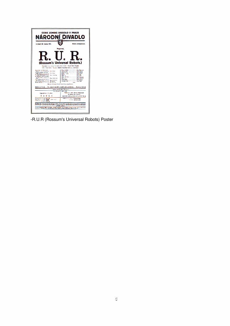
The word “Robot" first appeared in the play “R.U.R (Rossum's Universal Robots)
from Karel Capek, Czech in 1920.
Capek expressed the relationship between technology growth and human society in a
pessimistic way in this play. The terms, “Robotics” was made from Isaac Asimov in March,
1942. In this book, Asimov had a positive aspect, not just negative aspect of Robot. In
this book, Asimov was set up as Robot has 3 basic laws to observe.
1) A robot may not injure a human being or, through inaction, allow a human being to
come to harm.
2) A robot must obey orders given it by human beings except where such orders would conflict with
the First Law.
3) A robot must protect its own existence as long as such protection does not conflict with the First
or Second Law.
The definitions of Robot were addressed from various Robot-related organizations.
However, meanings of Robot are not consistent between people.
Nowadays, there is a few similarity between human and industrial Robots. In other words,
industrial robot does not have similar appearance, does not perform similar actions either.
Instead, Robot has one or more arms, and works in one spot. Future Robots will have
much more sense, intelligent and quality service technology, however, there still would be
the limitations, if you compare with human being. However, you can not deny that Robot is
getting intelligent like human beings as time goes by. Recently, Artificial intelligence and
Sensory perception technology is evolving quickly. By this reason, intelligent Robot will
be increased in the areas of applying industrial Robots.
6
-R.U.R (Rossum's Universal Robots) Poster
7
11..22 OOrriiggiinn ooff RRoobboott
Except the early stage of human’s history, you will see the close correlation between Robot
and industrial situation, social issues, computers, mechanics, unversials if you just look at
the Robot’s recent history. From the Rossum’s Universal Robots (written by Karel Capek),
to Flash Gordon, Metropolis, Lost In Space, The Day The Earth stood still, I-Robot, Robot
even performs humans’ jobs, such as, R2,D2, C3PO, Robo Cop, I Robot.
Let’s find out the Intelligent Robot’s history in accordance with industrial growth and social
trend/paradigm.
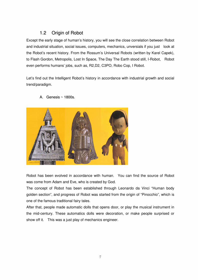
AA.. GGeenneessiiss ~~ 11880000ss..
Robot has been evolved in accordance with human. You can find the source of Robot
was come from Adam and Eve, who is created by God.
The concept of Robot has been established through Leonardo da Vinci “Human body
golden section”, and progress of Robot was started from the origin of “Pinocchio”, which is
one of the famous traditional fairy tales.
After that, people made automatic dolls that opens door, or play the musical instrument in
the mid-century. These automatics dolls were decoration, or make people surprised or
show off it. This was a just play of mechanics engineer.
8
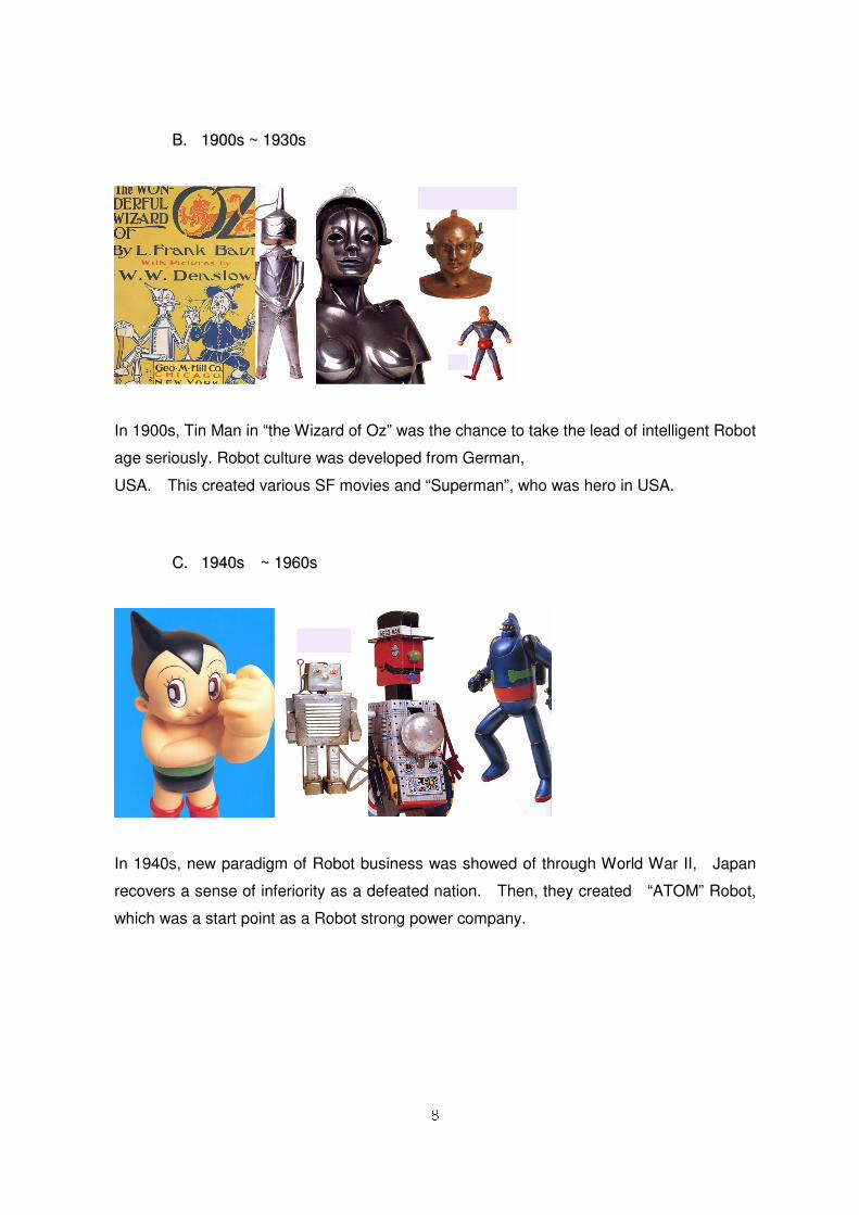
BB.. 11990000ss ~~ 11993300ss
In 1900s, Tin Man in “the Wizard of Oz” was the chance to take the lead of intelligent Robot
age seriously. Robot culture was developed from German,
USA. This created various SF movies and “Superman”, who was hero in USA.
CC.. 11994400ss ~~ 11996600ss
In 1940s, new paradigm of Robot business was showed of through World War II, Japan
recovers a sense of inferiority as a defeated nation. Then, they created “ATOM” Robot,
which was a start point as a Robot strong power company.
9
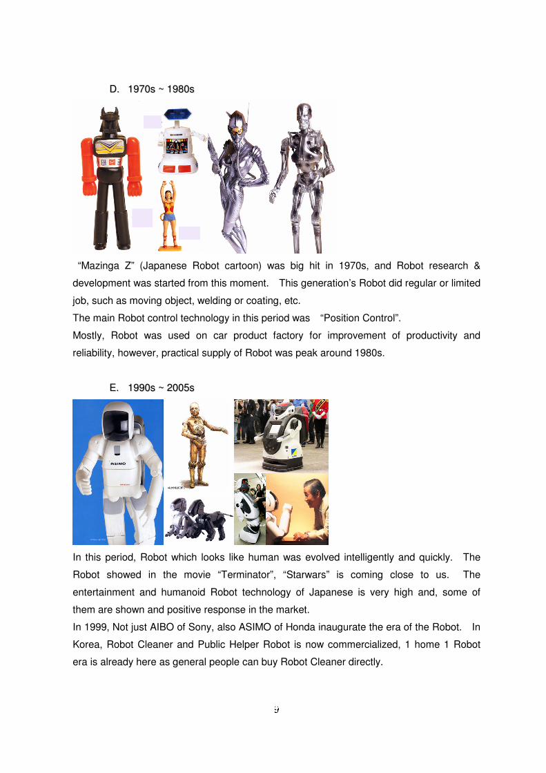
DD.. 11997700ss ~~ 11998800ss
“Mazinga Z” (Japanese Robot cartoon) was big hit in 1970s, and Robot research &
development was started from this moment. This generation’s Robot did regular or limited
job, such as moving object, welding or coating, etc.
The main Robot control technology in this period was “Position Control”.
Mostly, Robot was used on car product factory for improvement of productivity and
reliability, however, practical supply of Robot was peak around 1980s.
EE.. 11999900ss ~~ 22000055ss
In this period, Robot which looks like human was evolved intelligently and quickly. The
Robot showed in the movie “Terminator”, “Starwars” is coming close to us. The
entertainment and humanoid Robot technology of Japanese is very high and, some of
them are shown and positive response in the market.
In 1999, Not just AIBO of Sony, also ASIMO of Honda inaugurate the era of the Robot. In
Korea, Robot Cleaner and Public Helper Robot is now commercialized, 1 home 1 Robot
era is already here as general people can buy Robot Cleaner directly.
10
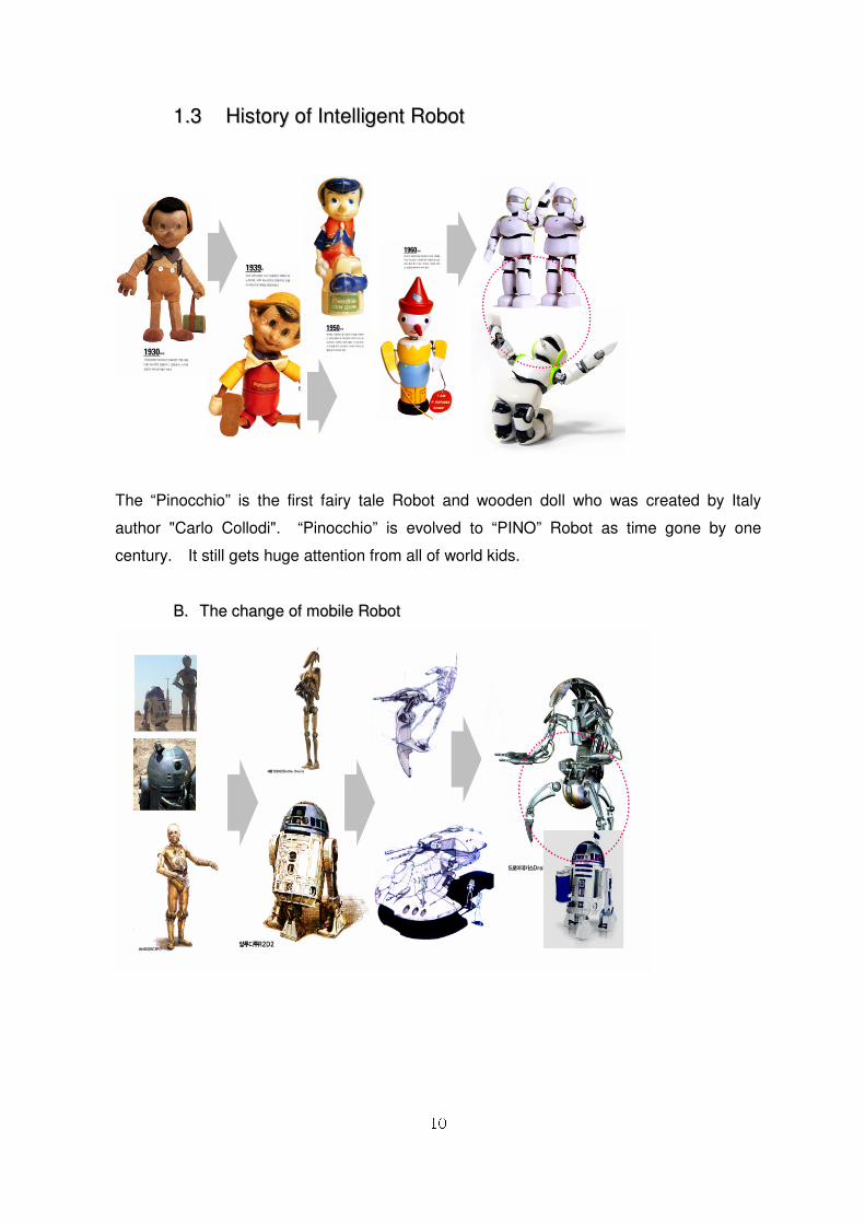
11..33 HHiissttoorryy ooff IInntteelllliiggeenntt RRoobboott
The “Pinocchio” is the first fairy tale Robot and wooden doll who was created by Italy
author "Carlo Collodi". “Pinocchio” is evolved to “PINO” Robot as time gone by one
century. It still gets huge attention from all of world kids.
BB.. TThhee cchhaannggee ooff mmoobbiillee RRoobboott
11
In 1980s, Android Robot is shown just like human being, this brought to Robot character
industry actively. In 1982, the movie “ET” was huge impact in this industry. After that,
“Terminator”, “Robo Cop” was the symbol of cyber Robot. And the movie “Starwars” was
the textbook of all Robots.
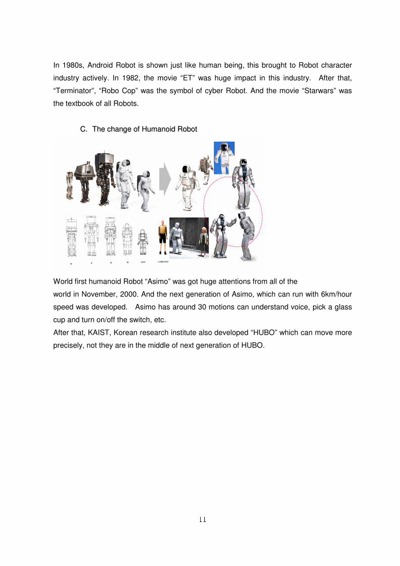
CC.. TThhee cchhaannggee ooff HHuummaannooiidd RRoobboott
World first humanoid Robot “Asimo” was got huge attentions from all of the
world in November, 2000. And the next generation of Asimo, which can run with 6km/hour
speed was developed. Asimo has around 30 motions can understand voice, pick a glass
cup and turn on/off the switch, etc.
After that, KAIST, Korean research institute also developed “HUBO” which can move more
precisely, not they are in the middle of next generation of HUBO.
12
11..44 IInntteelllliiggeenntt RRoobboott SSttrruuccttuurree
In 21c society, Robot is as a innovative fusion technology, living with human, or doing jobs
for human in order to give new life to human. This is what we called “Intelligent Robot
System”.
Intelligent Robot like human, interacts and share the residential area with people. This kind
of Robot is based on artificial intelligence, brain engineering, micro electro-mechanics, Bio
and Nano technology.
Let’s find out details in this chapter.
AA.. PPuubblliicc HHeellppeerr RRoobboott
Public helper Robot is based on the voice and visual recognition in order to interact with
visitors, and give the service to the people. For example, people ask “Where is toilet?” then,
Robot should guide the directions by using Robot arms and UI display. Further, Robot
gives practical service, such as guide contents, recognition service, environment
recognition based on sensor network. In order to do this, Robot must have UI display and
the degree of freedom just like human structure.
aa.. MMaaiinn SSeerrvviiccee
Intelligent Robot has addition functions Comfortable, Stable, Enjoy factors except basic 3
laws to live with human together. With these factors, people can have the better life quality.
The main purpose of public helper Robot is serving the people in certain space. Therefore,
it need as the following services basically.
13
Section Function Description
Guide
Guide and Assist Guide and exhibition show explanation
General Info. Service Serve news, weather, traffic & travel Info.
Drive Guide Guide and road navigation
Handicapped Guide Object transport and road navigation
Entrance Reception Work as a receptionist in exhibition show
Foreigner Guide Guide foreigners with their language
Security Security Record Monitoring situation - Mobile DVR concept
Remote Monitor Remote control monitoring by Robot
Entertainment
Receive Suggestion Receive the suggestions for improvement
A.O.D/V.O.D Robot dance with new hit song or m/v
Network Printer
Service Own photo-sticker service
Education Contents Fairy tale, song and Flash Animation contents
Mini-Game Mini game, game event link with Robot
General functions of the above stated can be used as Robot downloads the
resources from independent server by network system. Robot can conduct these functions
as it is structured.
BB.. RRoobboott CClleeaanneerr
Robot was used to industrial field, such as, assembling, factory and welding, etc. But now,
Robot is home. Recently, Robot cleaner is getting popular as people want to have well-
being life. Home service Robot is nowadays actively ongoing, so Robot is quite closely
connected with our life. The advantage of Robot cleaner is that it could reduce the labor
cost and comfortable. The state-of-art vacuum cleaner is coming out to the market
innumerably, but people should to the cleaning jobs. Therefore, Robot cleaner is the best
solution to get ride of complaining of chore jobs.
14
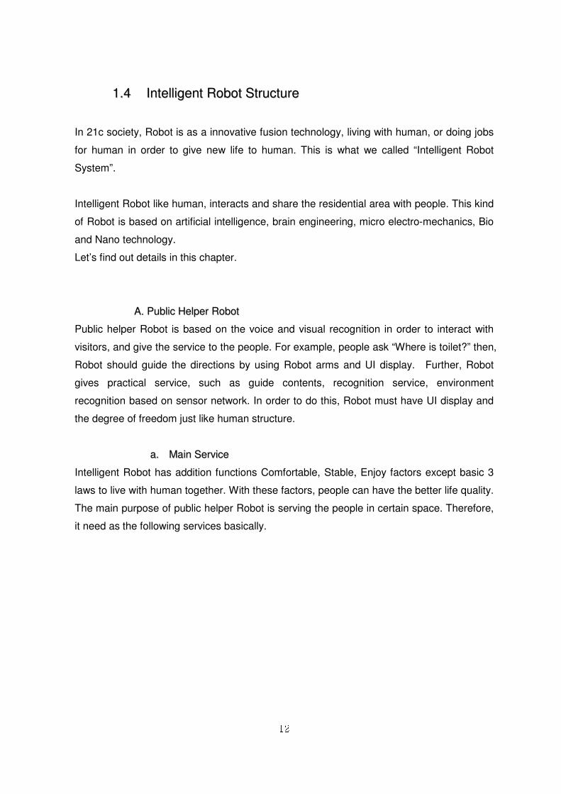
aa.. RRoobboott CClleeaanneerr CCllaassssiiffiiccaattiioonn ① Basic type
It operates by changing the path if there are walls or obstacles since it has collision sensor.
Moving path is not predicted, therefore, around 80~90% cleaning job can be done if it
works long time.
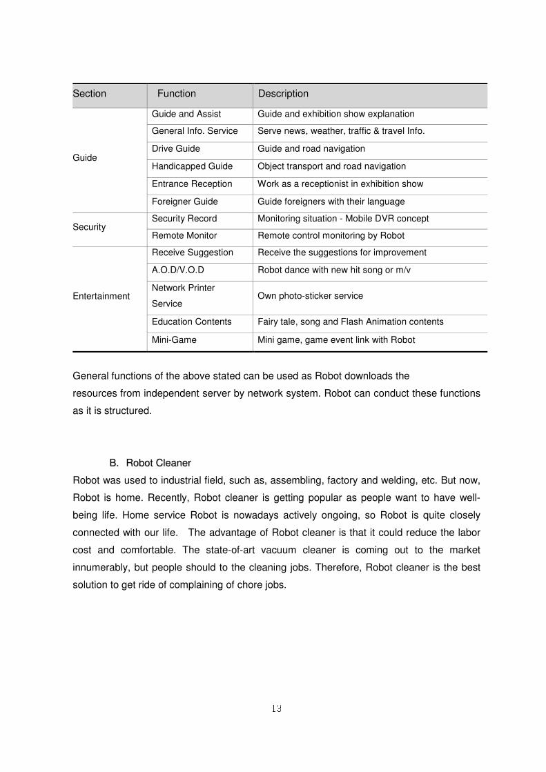
- Basic type Robot Cleaner
The principle of operation is that it controls motion by simple collision sensor switch, or ball
type that is changed the direction if there is any collision. It uses non-weaven cloth,
therefore, it absorb the small dust and hair by static electricity. In this Robot cleaner, it has
bumper switch, detect sensor, rotation brush, low power absorption motor.
- Basic type Robot cleaner structure
Robot cleaner uses and mix up the spiral, random, object detection algorithm for cleaning
method.
15
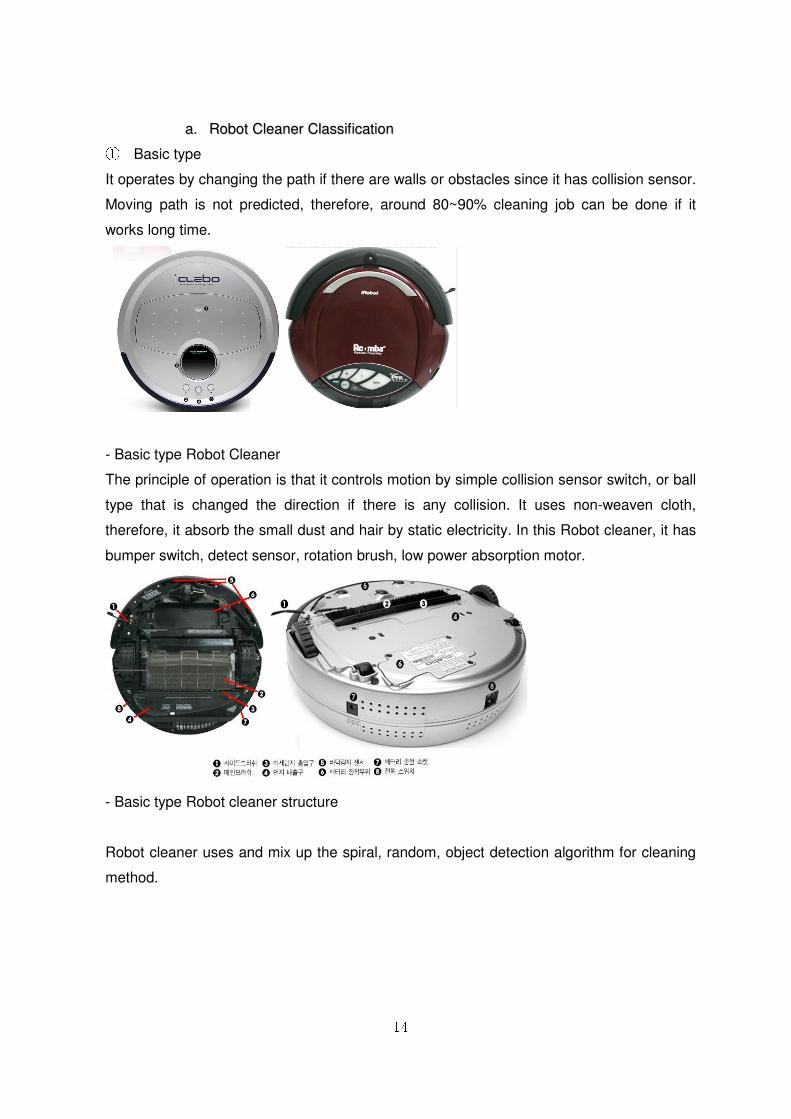
② Intermediate function style
Movement algorithm is basically same as the basic type, but it has automatic charging
function, movement path control function and security function.
[Intermediate function style]
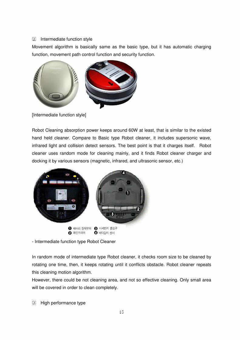
Robot Cleaning absorption power keeps around 60W at least, that is similar to the existed
hand held cleaner. Compare to Basic type Robot cleaner, it includes supersonic wave,
infrared light and collision detect sensors. The best point is that it charges itself. Robot
cleaner uses random mode for cleaning mainly, and it finds Robot cleaner charger and
docking it by various sensors (magnetic, infrared, and ultrasonic sensor, etc.)
- Intermediate function type Robot Cleaner
In random mode of intermediate type Robot cleaner, it checks room size to be cleaned by
rotating one time, then, it keeps rotating until it conflicts obstacle. Robot cleaner repeats
this cleaning motion algorithm.
However, there could be not cleaning area, and not so effective cleaning. Only small area
will be covered in order to clean completely.
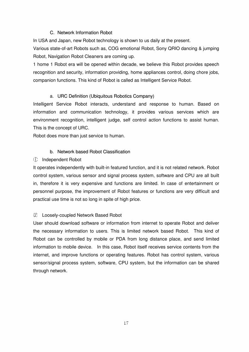
③ High performance type
16
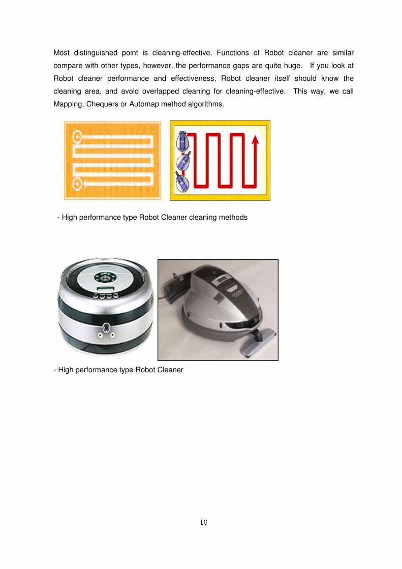
Most distinguished point is cleaning-effective. Functions of Robot cleaner are similar
compare with other types, however, the performance gaps are quite huge. If you look at
Robot cleaner performance and effectiveness, Robot cleaner itself should know the
cleaning area, and avoid overlapped cleaning for cleaning-effective. This way, we call
Mapping, Chequers or Automap method algorithms.
- High performance type Robot Cleaner cleaning methods
- High performance type Robot Cleaner
17
CC.. NNeettwwoorrkk IInnffoorrmmaattiioonn RRoobboott
In USA and Japan, new Robot technology is shown to us daily at the present.
Various state-of-art Robots such as, COG emotional Robot, Sony QRIO dancing & jumping
Robot, Navigation Robot Cleaners are coming up.
1 home 1 Robot era will be opened within decade, we believe this Robot provides speech
recognition and security, information providing, home appliances control, doing chore jobs,
companion functions. This kind of Robot is called as Intelligent Service Robot.
a. UURRCC DDeeffiinniittiioonn ((UUbbiiqquuiittoouuss RRoobboottiiccss CCoommppaannyy))
Intelligent Service Robot interacts, understand and response to human. Based on
information and communication technology, it provides various services which are
environment recognition, intelligent judge, self control action functions to assist human.
This is the concept of URC.
Robot does more than just service to human.
bb.. NNeettwwoorrkk bbaasseedd RRoobboott CCllaassssiiffiiccaattiioonn ① Independent Robot
It operates independently with built-in featured function, and it is not related network. Robot
control system, various sensor and signal process system, software and CPU are all built
in, therefore it is very expensive and functions are limited. In case of entertainment or
personnel purpose, the improvement of Robot features or functions are very difficult and
practical use time is not so long in spite of high price.
② Loosely-coupled Network Based Robot
User should download software or information from internet to operate Robot and deliver
the necessary information to users. This is limited network based Robot. This kind of
Robot can be controlled by mobile or PDA from long distance place, and send limited
information to mobile device. In this case, Robot itself receives service contents from the
internet, and improve functions or operating features. Robot has control system, various
sensor/signal process system, software, CPU system, but the information can be shared
through network.
18
③ Closely-coupled Network Based Robot
In this Robot, only controller, sensor interface and wireless communication interface are
included, and the rest parts, signal process, control or AI function can be used from
network resources. This Robot does not need mass capacity operation, so, price can be
reduced and it uses required Robot platform, therefore, various services would be available.
Network technology for real-time transmission of mass capacity of data, Robot core
technology to correspond environment variation, distributed high performance server
system to provide artificial intelligence service are prerequisite Robot technologies,
because mass capacity of sensor data is transferred by cable or wireless communication.
In this case, user purchase low price Robot, then pay and download required useful
contents or various information just like mobile phone.
④ Sensor Network Based Robot
This Robot uses sensor network in environment. we can extract and use the environment
information from installed sensor network, if network usage is revitalized. Various area
would be applicable and increase reliability of Robot control and artificial intelligent function.
19
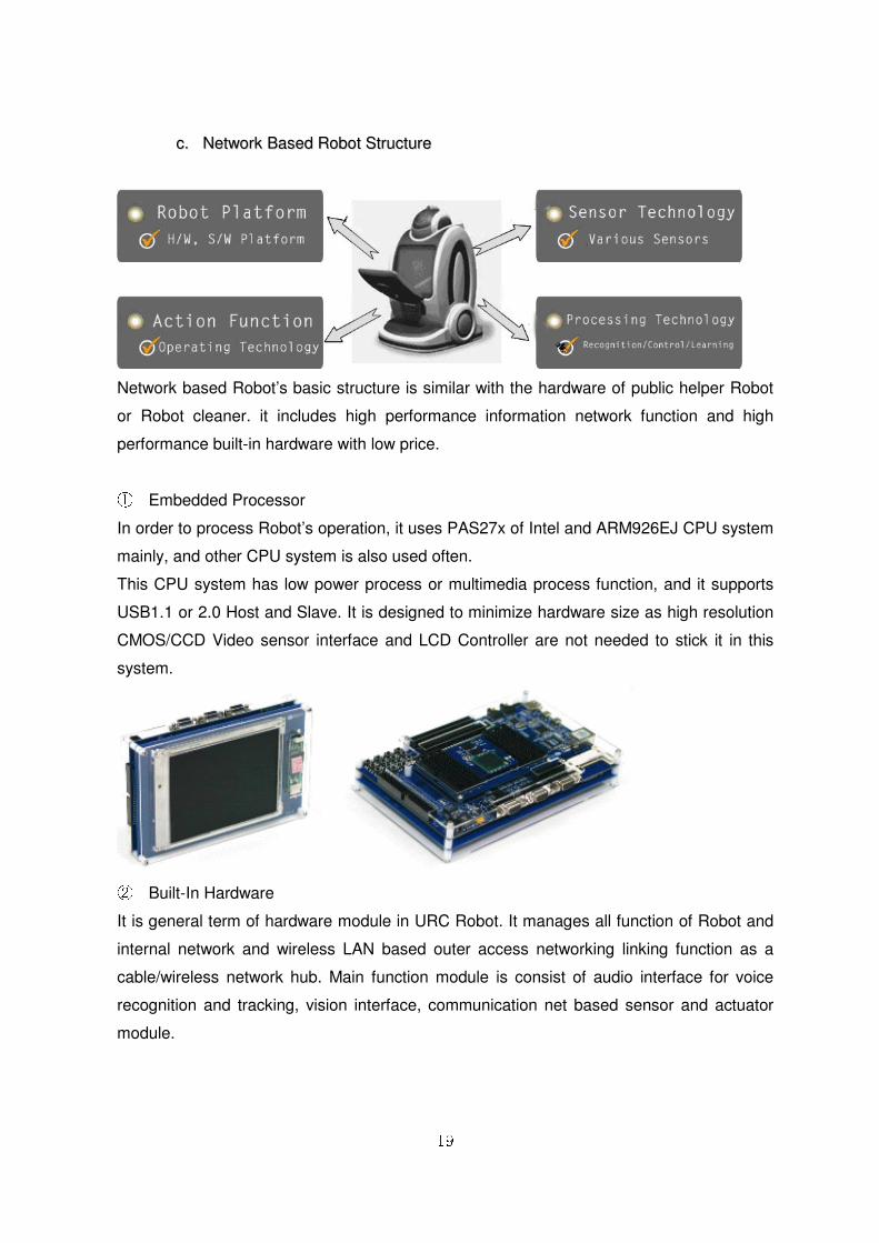
cc.. NNeettwwoorrkk BBaasseedd RRoobboott SSttrruuccttuurree
Network based Robot’s basic structure is similar with the hardware of public helper Robot
or Robot cleaner. it includes high performance information network function and high
performance built-in hardware with low price.
① Embedded Processor
In order to process Robot’s operation, it uses PAS27x of Intel and ARM926EJ CPU system
mainly, and other CPU system is also used often.
This CPU system has low power process or multimedia process function, and it supports
USB1.1 or 2.0 Host and Slave. It is designed to minimize hardware size as high resolution
CMOS/CCD Video sensor interface and LCD Controller are not needed to stick it in this
system.
② Built-In Hardware
It is general term of hardware module in URC Robot. It manages all function of Robot and
internal network and wireless LAN based outer access networking linking function as a
cable/wireless network hub. Main function module is consist of audio interface for voice
recognition and tracking, vision interface, communication net based sensor and actuator
module.
20
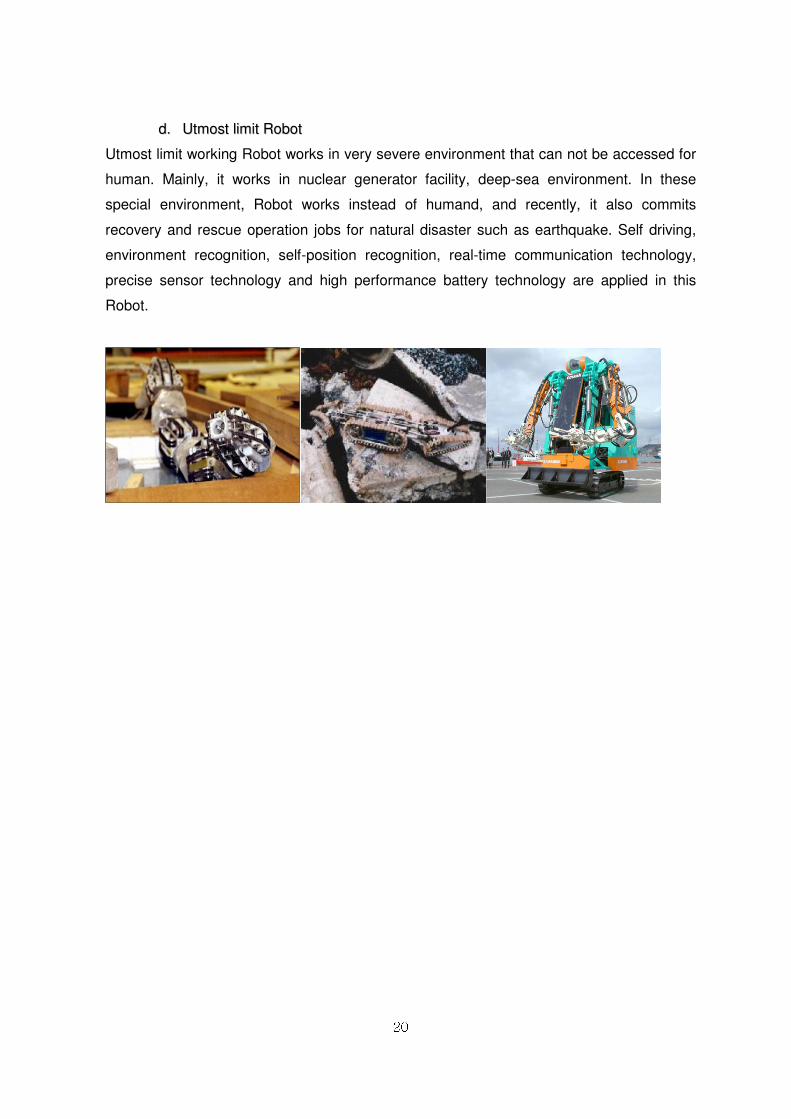
dd.. UUttmmoosstt lliimmiitt RRoobboott
Utmost limit working Robot works in very severe environment that can not be accessed for
human. Mainly, it works in nuclear generator facility, deep-sea environment. In these
special environment, Robot works instead of humand, and recently, it also commits
recovery and rescue operation jobs for natural disaster such as earthquake. Self driving,
environment recognition, self-position recognition, real-time communication technology,
precise sensor technology and high performance battery technology are applied in this
Robot.
21
22.. RRoobbooBBuuiillddeerr IInnttrroodduuccttiioonn
22..11 OOvveerrvviieeww
RoboBuilder has been established to change the stereotype “Robot is Difficult”. The main
concept of RoboBuilder is “Robot is easy and fun” to maximize Robot market. For this
reason, it is focused on creativity, smooth and powerful Robot motion, sound, high latitude
LED in order to make freely by using intelligence servo motors. This allows to develop new
Robot culture focused on Robot contents such as UCC. Furthermore, RoboBuilder
provides various Robot programming methods and curriculums, from beginners to Robot
experts, such as RoboBuilder MSRDS programming basic course, C programming, Lab
View tutorials and courses.
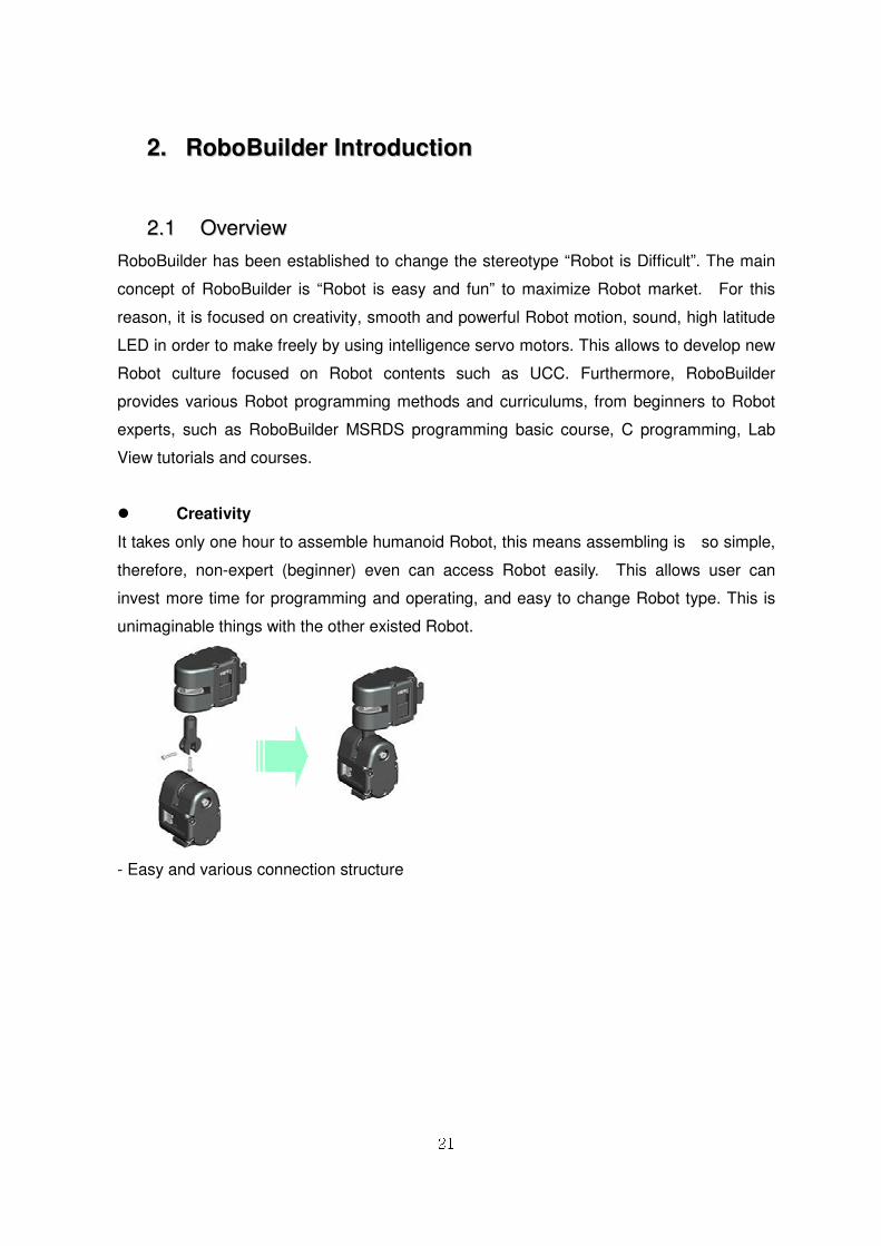
� Creativity
It takes only one hour to assemble humanoid Robot, this means assembling is so simple,
therefore, non-expert (beginner) even can access Robot easily. This allows user can
invest more time for programming and operating, and easy to change Robot type. This is
unimaginable things with the other existed Robot.
- Easy and various connection structure
22
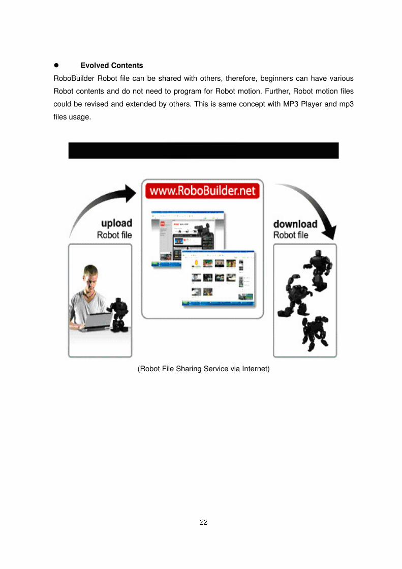
� Evolved Contents
RoboBuilder Robot file can be shared with others, therefore, beginners can have various
Robot contents and do not need to program for Robot motion. Further, Robot motion files
could be revised and extended by others. This is same concept with MP3 Player and mp3
files usage.
(Robot File Sharing Service via Internet)
23
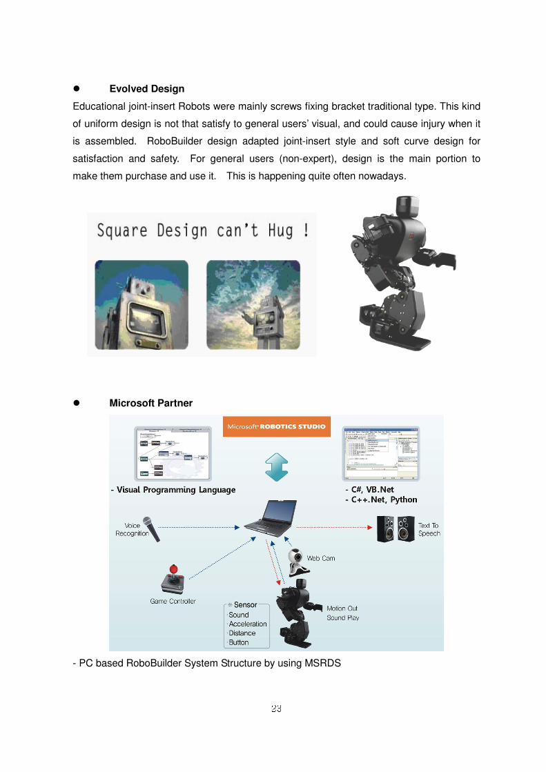
� Evolved Design
Educational joint-insert Robots were mainly screws fixing bracket traditional type. This kind
of uniform design is not that satisfy to general users’ visual, and could cause injury when it
is assembled. RoboBuilder design adapted joint-insert style and soft curve design for
satisfaction and safety. For general users (non-expert), design is the main portion to
make them purchase and use it. This is happening quite often nowadays.
� Microsoft Partner
- PC based RoboBuilder System Structure by using MSRDS
24
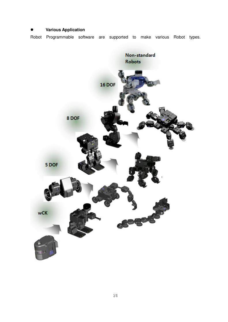
� Various Application
Robot Programmable software are supported to make various Robot types.
25
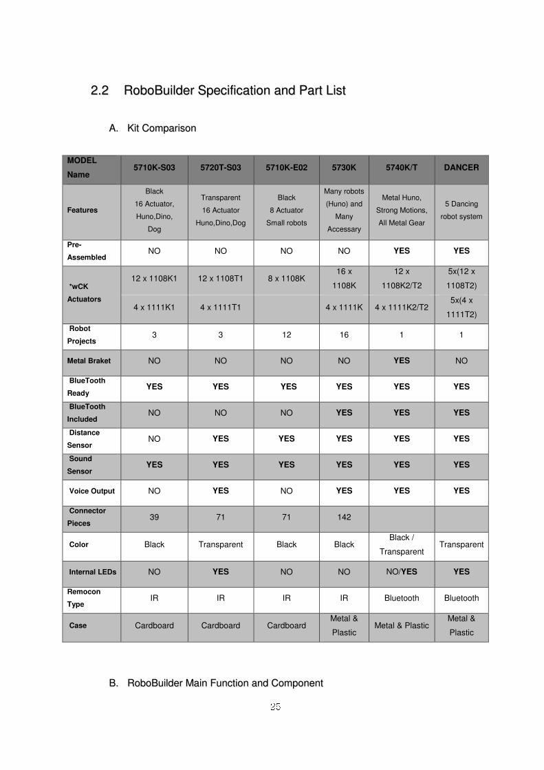
22..22 RRoobbooBBuuiillddeerr SSppeecciiffiiccaattiioonn aanndd PPaarrtt LLiisstt
AA.. KKiitt CCoommppaarriissoonn
MODEL
Name 5710K-S03 5720T-S03 5710K-E02 5730K 5740K/T DANCER
Features
Black
16 Actuator,
Huno,Dino,
Dog
Transparent
16 Actuator
Huno,Dino,Dog
Black
8 Actuator
Small robots
Many robots
(Huno) and
Many
Accessary
Metal Huno,
Strong Motions,
All Metal Gear
5 Dancing
robot system
Pre-
Assembled NO NO NO NO YES YES
*wCK
Actuators
12 x 1108K1 12 x 1108T1 8 x 1108K 16 x
1108K
12 x
1108K2/T2
5x(12 x
1108T2)
4 x 1111K1 4 x 1111T1 4 x 1111K 4 x 1111K2/T2 5x(4 x
1111T2)
Robot
Projects 3 3 12 16 1 1
Metal Braket NO NO NO NO YES NO
BlueTooth
Ready YES YES YES YES YES YES
BlueTooth
Included NO NO NO YES YES YES
Distance
Sensor NO YES YES YES YES YES
Sound
Sensor YES YES YES YES YES YES
Voice Output NO YES NO YES YES YES
Connector
Pieces 39 71 71 142
Color Black Transparent Black Black Black /
Transparent Transparent
Internal LEDs NO YES NO NO NO/YES YES
Remocon
Type IR IR IR IR Bluetooth Bluetooth
Case Cardboard Cardboard Cardboard Metal &
Plastic Metal & Plastic
Metal &
Plastic
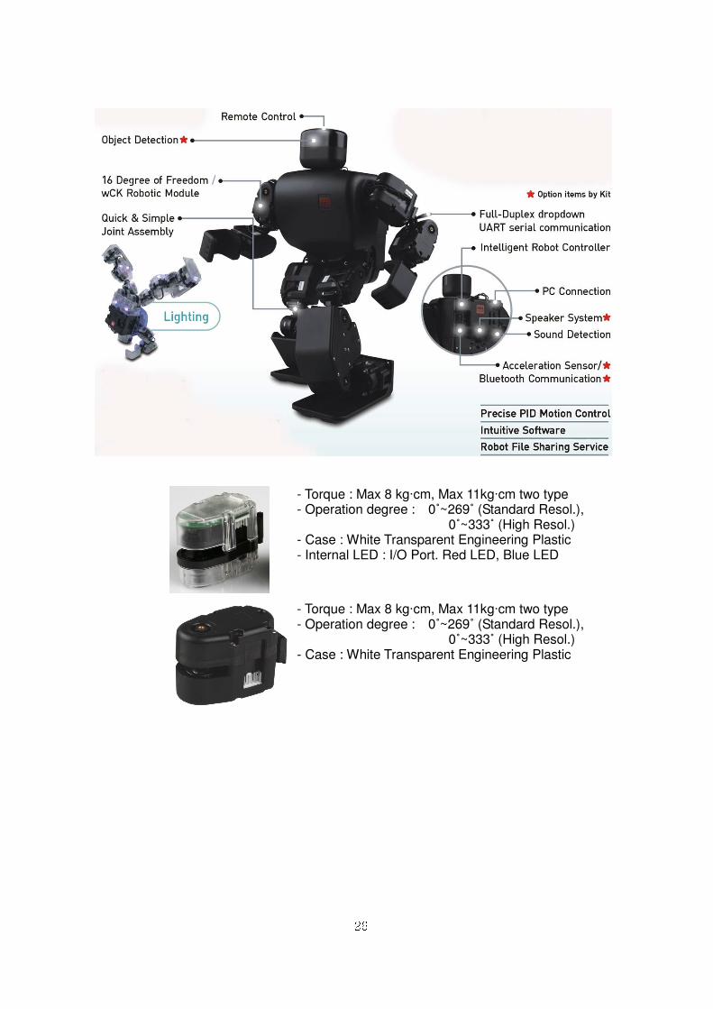
BB.. RRoobbooBBuuiillddeerr MMaaiinn FFuunnccttiioonn aanndd CCoommppoonneenntt
26
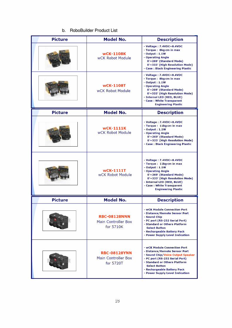
- Torque : Max 8 kg·cm, Max 11kg·cm two type - Operation degree : 0˚~269˚ (Standard Resol.), 0˚~333˚ (High Resol.) - Case : White Transparent Engineering Plastic - Internal LED : I/O Port. Red LED, Blue LED
- Torque : Max 8 kg·cm, Max 11kg·cm two type - Operation degree : 0˚~269˚ (Standard Resol.), 0˚~333˚ (High Resol.) - Case : White Transparent Engineering Plastic
27
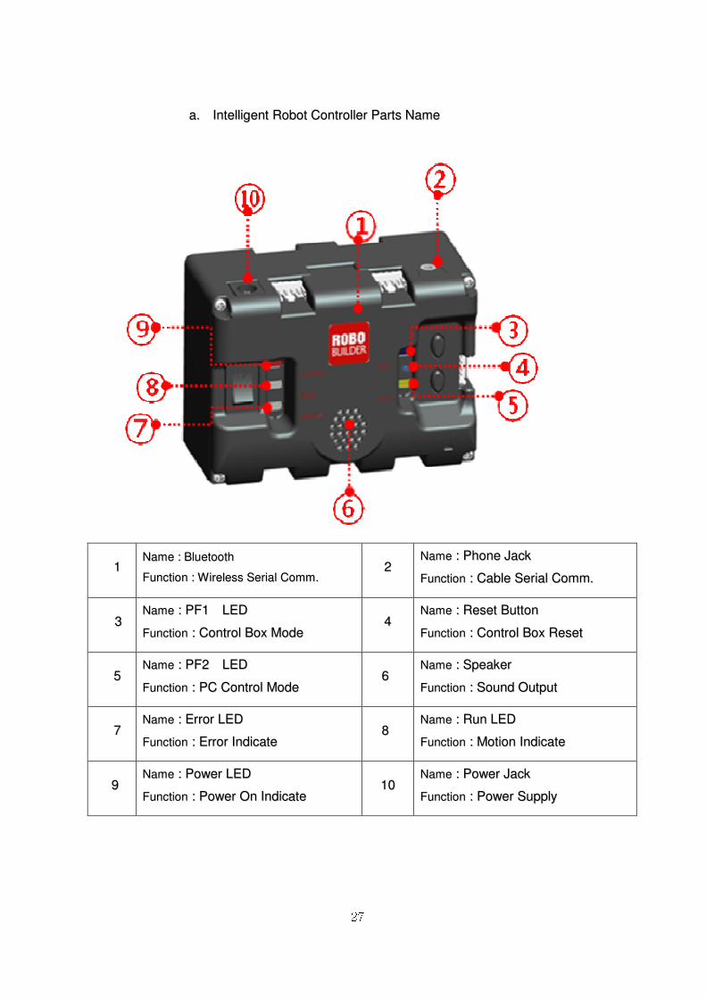
aa.. IInntteelllliiggeenntt RRoobboott CCoonnttrroolllleerr PPaarrttss NNaammee
11 NNaammee :: BBlluueettooootthh
FFuunnccttiioonn :: WWiirreelleessss SSeerriiaall CCoommmm.. 22
NNaammee :: PPhhoonnee JJaacckk
FFuunnccttiioonn :: CCaabbllee SSeerriiaall CCoommmm..
33 NNaammee :: PPFF11 LLEEDD
FFuunnccttiioonn :: CCoonnttrrooll BBooxx MMooddee 44
NNaammee :: RReesseett BBuuttttoonn
FFuunnccttiioonn :: CCoonnttrrooll BBooxx RReesseett
55 NNaammee :: PPFF22 LLEEDD
FFuunnccttiioonn :: PPCC CCoonnttrrooll MMooddee 66
NNaammee :: SSppeeaakkeerr
FFuunnccttiioonn :: SSoouunndd OOuuttppuutt
77 NNaammee :: EErrrroorr LLEEDD
FFuunnccttiioonn :: EErrrroorr IInnddiiccaattee 88
NNaammee :: RRuunn LLEEDD
FFuunnccttiioonn :: MMoottiioonn IInnddiiccaattee
99 NNaammee :: PPoowweerr LLEEDD
FFuunnccttiioonn :: PPoowweerr OOnn IInnddiiccaattee 1100
NNaammee :: PPoowweerr JJaacckk
FFuunnccttiioonn :: PPoowweerr SSuuppppllyy
28
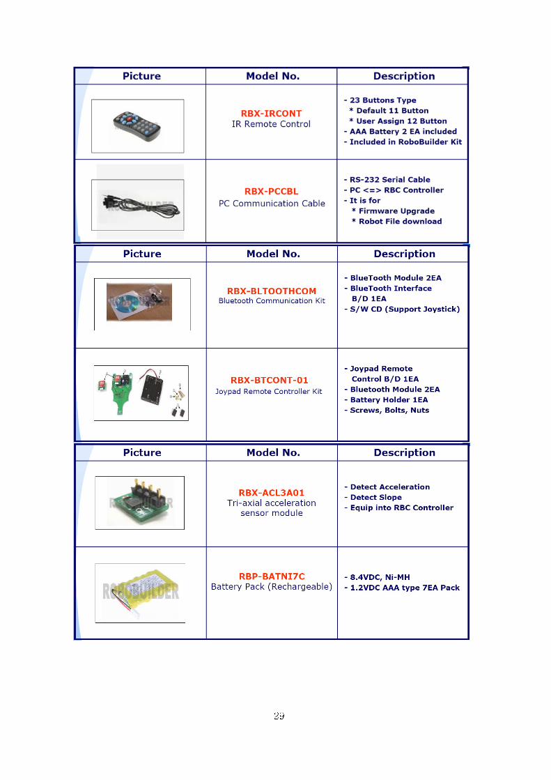
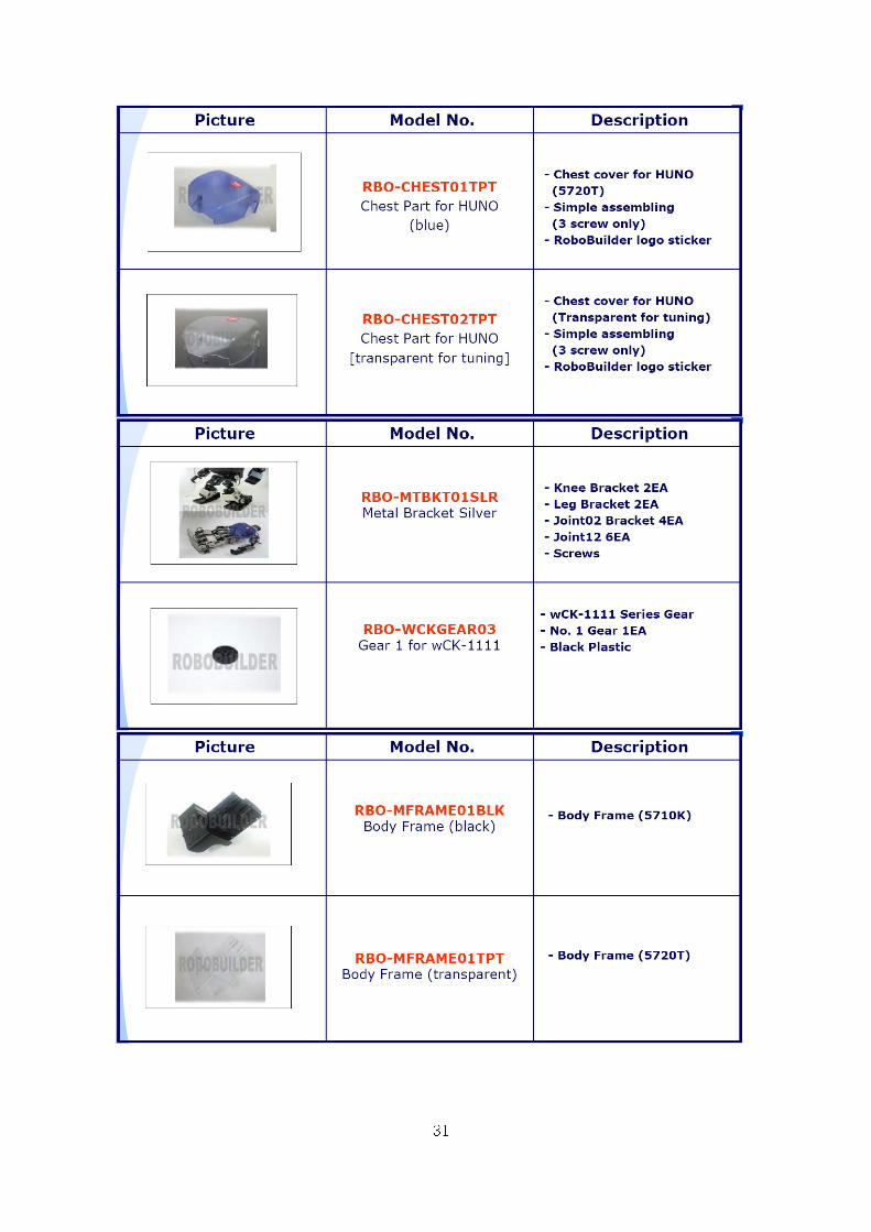
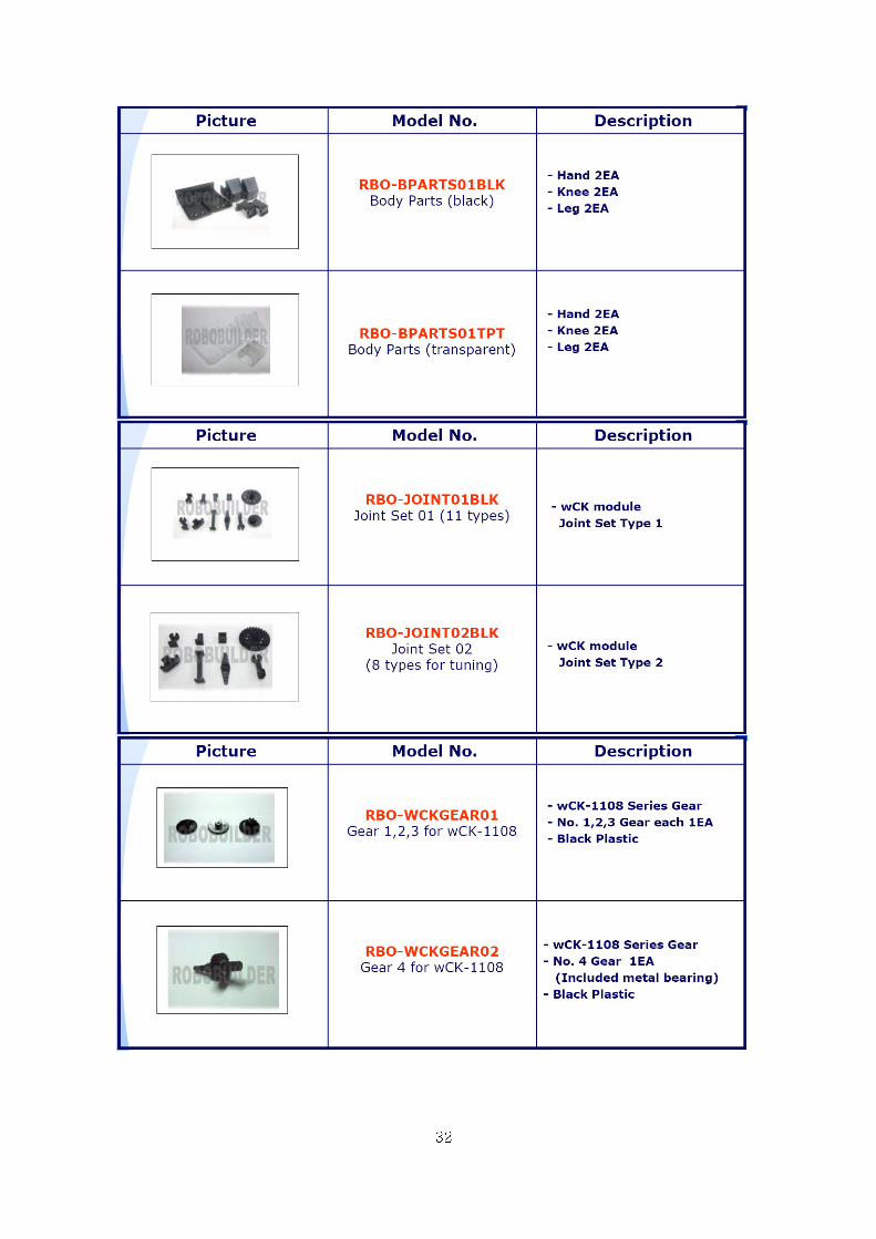
bb.. RRoobbooBBuuiillddeerr PPrroodduucctt LLiisstt
29

30
31
32
33
34
33.. MMiiccrroossoofftt RRoobboottiiccss SSttuuddiioo((MMSSRRDDSS))
33..11 OOvveerrvviieeww
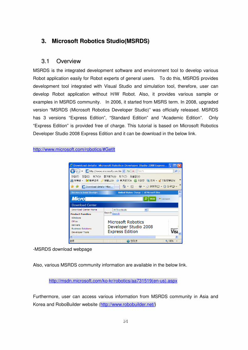
MSRDS is the integrated development software and environment tool to develop various
Robot application easily for Robot experts of general users. To do this, MSRDS provides
development tool integrated with Visual Studio and simulation tool, therefore, user can
develop Robot application without H/W Robot. Also, it provides various sample or
examples in MSRDS community. In 2006, it started from MSRS term. In 2008, upgraded
version “MSRDS (Microsoft Robotics Developer Studio)” was officially released. MSRDS
has 3 versions “Express Edition”, “Standard Edition” and “Academic Edition”. Only
“Express Edition” is provided free of charge. This tutorial is based on Microsoft Robotics
Developer Studio 2008 Express Edition and it can be download in the below link.
http://www.microsoft.com/robotics/#GetIt
-MSRDS download webpage
Also, various MSRDS community information are available in the below link.
http://msdn.microsoft.com/ko-kr/robotics/aa731519(en-us).aspx
Furthermore, user can access various information from MSRDS community in Asia and
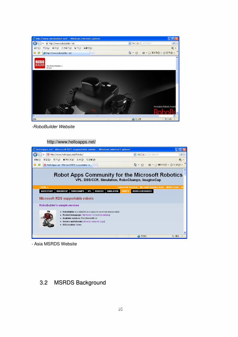
Korea and RoboBuilder website (http://www.robobuilder.net/)
35
-RoboBuilder Website
http://www.helloapps.net/
- Asia MSRDS Website
33..22 MMSSRRDDSS BBaacckkggrroouunndd
36
Intelligent Robot is defined as a complex body that is included mechanics, electronics,
information and bio engineering technology. Robot is rapidly progressed since the first
industrial Robot was shown in 1960s. However, Robot is still in early stage to live with
human. To be used practically, more R&D and parts and material modulation technology is
needed.
Intelligent Robot development starts from initial development factors to intelligent service
factors such as, cleaning, sensing and recognition. Plus, human fellowship is added. By
this reason, initial development factors and modulation should be conducted in advance.
Unlike pre-existed home appliance, such as, microwave, washing machine, and refrigerator,
Robot product is integrated with various hardware or software, and it is transformed to new
product. We can tell Robot product is quite different from pre-existed home appliance
basically. However, every Robot product is used as dependence of certain hardware,
therefore it has not been re-used. Therefore, every Robot was developed from the initial
step. In order to solve these repetition and un-productivity problems, simulation
environment, easy software development tool and development community should be
provided.
In Robot development, hardware part and Robot OS should be done first so that user test
the software. For the final test, the same environment should be provided to apply the real
Robot into the real world. This is the present development huge problem.
As Robot simulation environment is provided, Robot software and hardware
development and field test, research result is quite predictable.
This allows reducing the R&D period and cost, also more practical product could be made.
To provide various services and contents, just like car and mobile, Robot application
program development tool is necessary condition for general users and Robot experts.
Easy development tool allows to make various application program and share with others
in community.
33..33 MMSSRRDDSS AApppplliiccaattiioonn
The core technology of MSRDS, CCR(Concurrency and Coordination Runtime) and
DSS(Decentralized System Services) is not just for Robot, also developed for next
37
generation OS(operating system). However, it has been released to “Robotics” because
intelligent Robot is considered as optimum condition.
DSS and CCR make modulation and object from many device. Also, it can integrate and
manage the sporadic data in web environment.
This is the optimum solution for universe satellite, ubiquitous environment by network,
military operation simulation, etc. MSRDS is still in early stage, therefore, MSRDS
application will be much more extended as time goes by.
Microsoft hold various MSRDS competition nowadays.
The representative competition is “RoboChamps”.
http://www.robochamps.com/
38
44.. HHaarrddwwaarree SSeettuupp
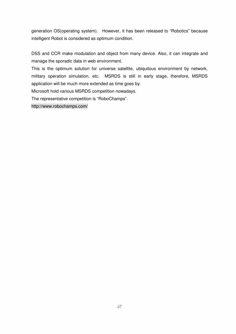
44..11 PPoowweerr SSuuppppllyy
1) Connect Adapter with AC power outlet as shown in figure ①.
2) Connect figure ① Adapter plug into Control Box jack.
3) Turn on Power button in figure ② Control Box.
39
44..22 HHooww TToo CChhaarrggee
① Press PF1 and PF2 at the same time more than 3 seconds after power on.
② Green LED is blinking when charging begins.
③ Battery operating time is depended on Robot’s motion. Generally, it works 20~30
minutes continuously.
40
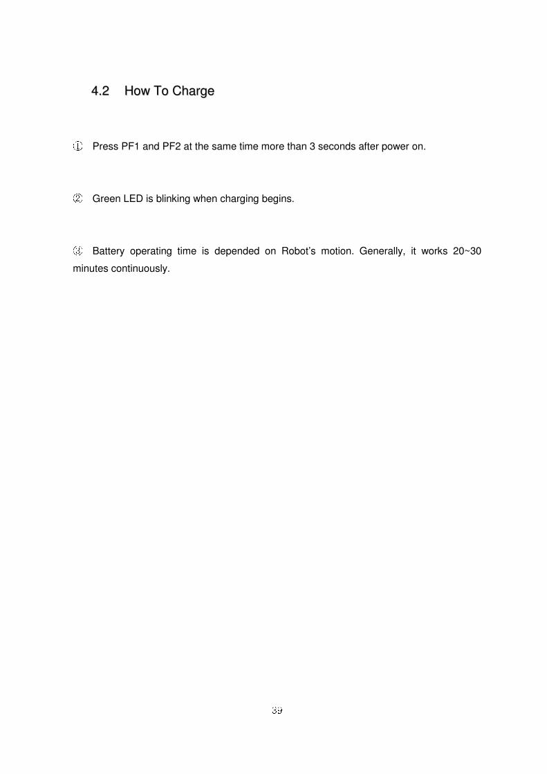
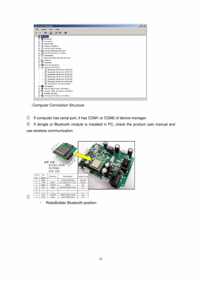
44..33 CCoommmmuunniiccaattiioonn wwiitthh PPCC
① Connect Serial Comm. cable with Control Box jack socket. ② Connect Serial Port cable with PC serial port. ③ Connect DSUB 9Pin with USB serial Port connecter. ④ “Device Driver” should be installed when USB-Serial converter cable is used
as shown in the below.
41
- Computer Connection Structure
⑤ If computer has serial port, it has COM1 or COM2 of device manager. ⑥ If dongle or Bluetooth module is installed in PC, check the product user manual and
use wireless communication.
⑦
- RoboBuilder Bluetooth position
42
55.. SSooffttwwaarree DDoowwnnllooaadd aanndd IInnssttaallllaattiioonn
55..11 RRoobbooBBuuiillddeerr SSooffttwwaarree
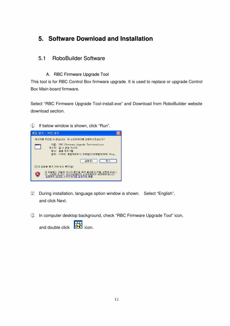
AA.. RRBBCC FFiirrmmwwaarree UUppggrraaddee TTooooll
This tool is for RBC Control Box firmware upgrade. It is used to replace or upgrade Control
Box Main-board firmware.
Select “RBC Firmware Upgrade Tool-install.exe” and Download from RoboBuilder website
download section.
① If below window is shown, click “Run”.
② During installation, language option window is shown. Select “English”,
and click Next.
③ In computer desktop background, check “RBC Firmware Upgrade Tool” icon,
and double click icon.
43
④ If “Could not find VB6K.DLL.” message is shown, click “Start -> All
Programs -> RoboBuilder-> RBC Firmware Upgrade Tool -> patch.exe
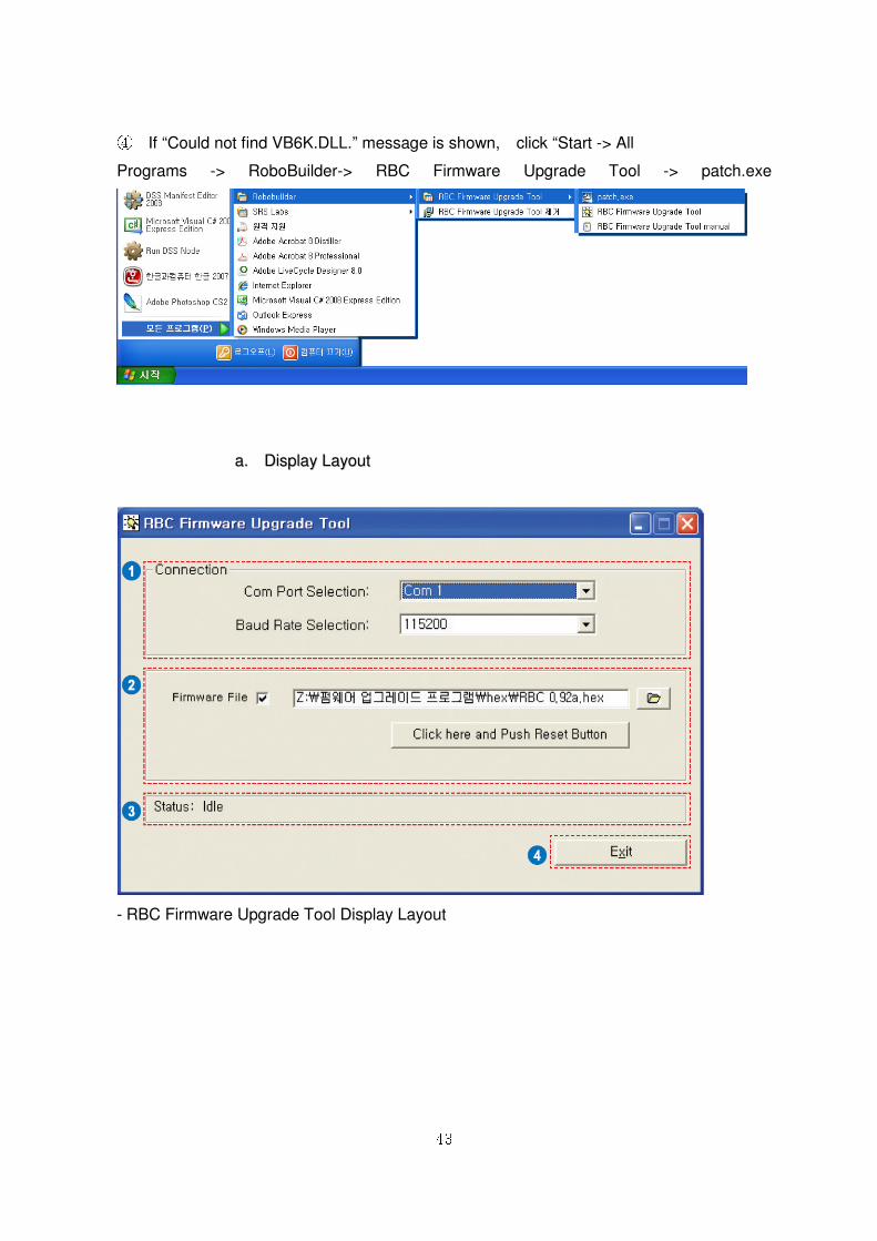
aa.. DDiissppllaayy LLaayyoouutt
- RBC Firmware Upgrade Tool Display Layout
44
① Connection Information : Select proper Serial port and Baud Rate Selection. For
proper serial Port, check in “device manager”. Baud Rate is mainly “115200”. ② File Selection : Select firmware file (*.hex) ③ Status : Show upgrade status. ④ Exit : End firmware upgrade program.
bb.. HHooww ttoo uussee
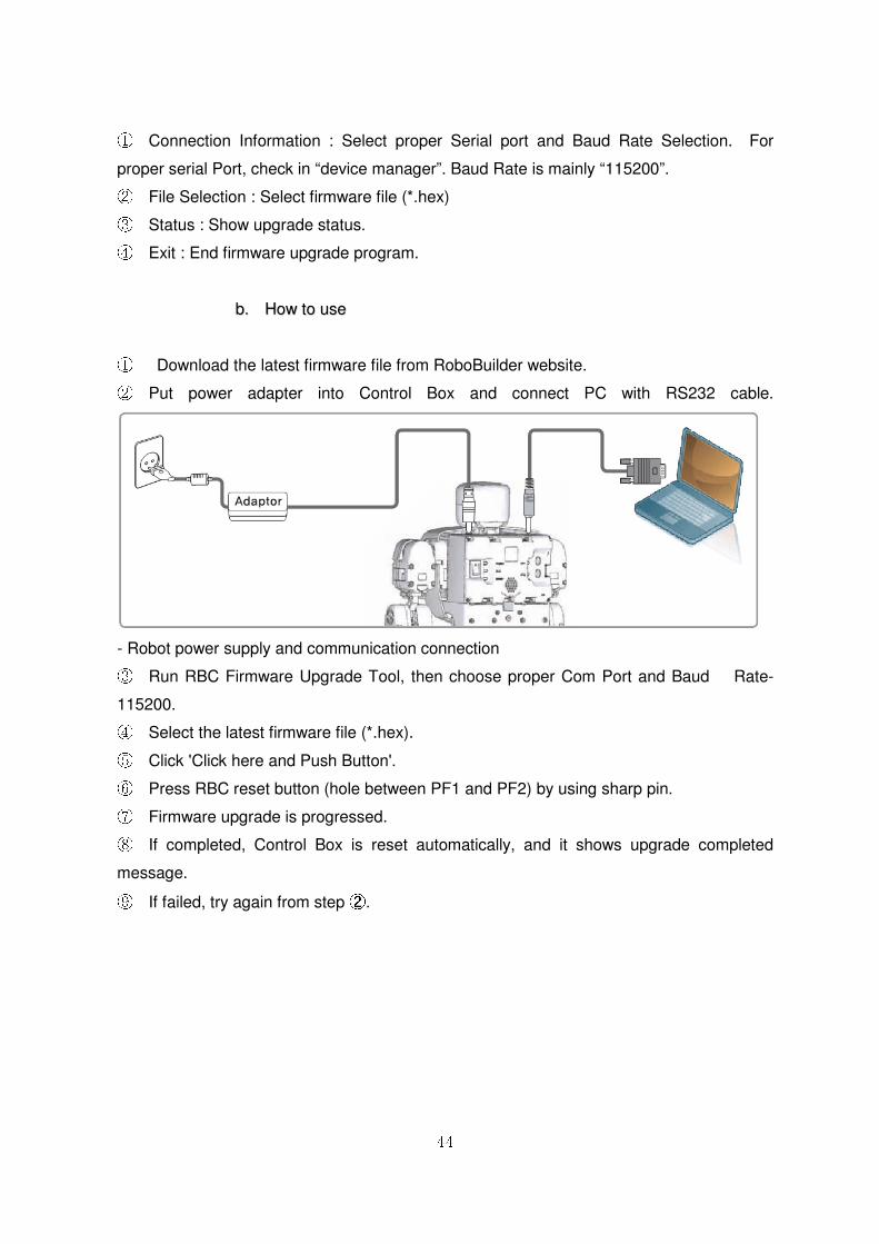
① Download the latest firmware file from RoboBuilder website. ② Put power adapter into Control Box and connect PC with RS232 cable.
- Robot power supply and communication connection ③ Run RBC Firmware Upgrade Tool, then choose proper Com Port and Baud Rate-
115200. ④ Select the latest firmware file (*.hex). ⑤ Click 'Click here and Push Button'. ⑥ Press RBC reset button (hole between PF1 and PF2) by using sharp pin. ⑦ Firmware upgrade is progressed. ⑧ If completed, Control Box is reset automatically, and it shows upgrade completed
message. ⑨ If failed, try again from step ②.
45
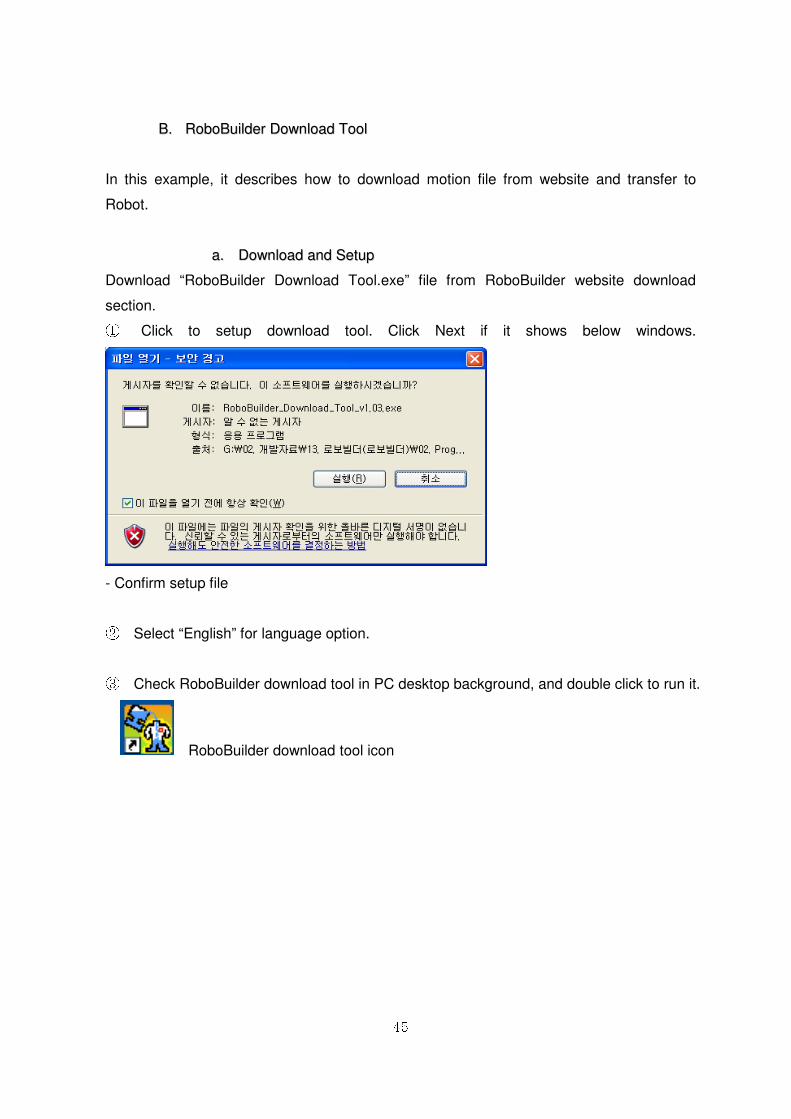
BB.. RRoobbooBBuuiillddeerr DDoowwnnllooaadd TTooooll
In this example, it describes how to download motion file from website and transfer to
Robot.
aa.. DDoowwnnllooaadd aanndd SSeettuupp
Download “RoboBuilder Download Tool.exe” file from RoboBuilder website download
section. ① Click to setup download tool. Click Next if it shows below windows.
- Confirm setup file
② Select “English” for language option.
③ Check RoboBuilder download tool in PC desktop background, and double click to run it.
RoboBuilder download tool icon
46
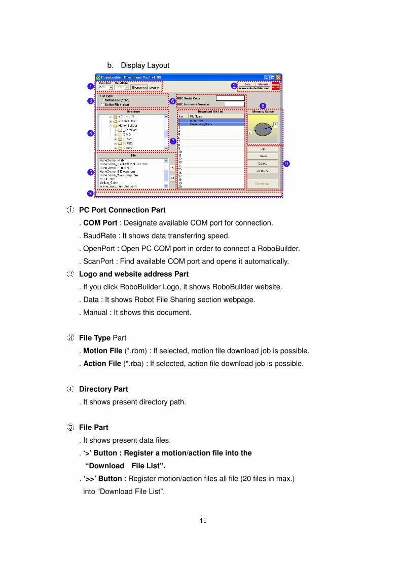
bb.. DDiissppllaayy LLaayyoouutt
① PC Port Connection Part
. COM Port : Designate available COM port for connection.
. BaudRate : It shows data transferring speed.
. OpenPort : Open PC COM port in order to connect a RoboBuilder.
. ScanPort : Find available COM port and opens it automatically. ② Logo and website address Part
. If you click RoboBuilder Logo, it shows RoboBuilder website.
. Data : It shows Robot File Sharing section webpage.
. Manual : It shows this document.
③ File Type Part
. Motion File (*.rbm) : If selected, motion file download job is possible.
. Action File (*.rba) : If selected, action file download job is possible.
④ Directory Part
. It shows present directory path.
⑤ File Part
. It shows present data files.
. ‘>’ Button : Register a motion/action file into the
“Download File List”.
. ‘>>’ Button : Register motion/action files all file (20 files in max.)
into “Download File List”.

47
⑥ RBC Information Part
. RBC Serial Code : It shows connected RoboBuilder Control Box
Serial Code.
. RBC Firmware Version : It shows present RoboBuilder Control Box
(RBC) firmware version.
⑦ Download File List Part
. It shows download file list. The background color will be changed according to
RoboBuilder platform type. And this color is similar with RBC platform LED.
. Blue : Creator HUNO, Pink : Creator DINO, Red : Creator DOGY, Orange :
⑧ Memory Space Part
. It shows available memory space in RBC memory after download files are
registered. “E” means, available space and, the number is registered file number.
The background of chart color is similar with RoboBuilder platform color indication.
⑨ File List Editing and Downloading Part
- Up Button : It moves the file to previous number position.
- Down Button : It move the file to next number position.
- Delete Button : It deletes selected file in the download file list.
- Delete All Button : It deletes all files in the download file list.
⑩ File Information Display Part
. It shows selected file information in detail.
. If motion file is selected, it shows file name, file size, robot platform, scene number,
performance time information. If action file is selected, it shows file name, file size,
robot platform, statements information.
48
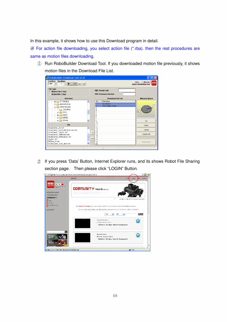
In this example, it shows how to use this Download program in detail. ※ For action file downloading, you select action file (*.rba). then the rest procedures are
same as motion files downloading. ① Run RoboBuilder Download Tool. If you downloaded motion file previously, it shows
motion files in the Download File List.
② If you press ‘Data’ Button, Internet Explorer runs, and its shows Robot File Sharing
section page. Then please click “LOGIN” Button.
49
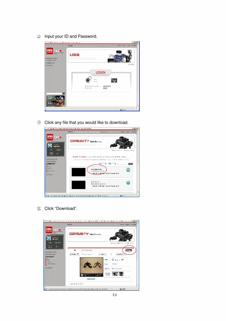
③ Input your ID and Password.
④ Click any file that you would like to download.
⑤ Click “Download”.
50
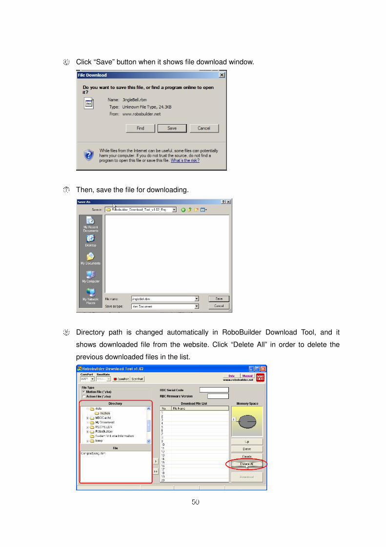
⑥ Click “Save” button when it shows file download window.
⑦ Then, save the file for downloading.
⑧ Directory path is changed automatically in RoboBuilder Download Tool, and it
shows downloaded file from the website. Click “Delete All” in order to delete the
previous downloaded files in the list.
51
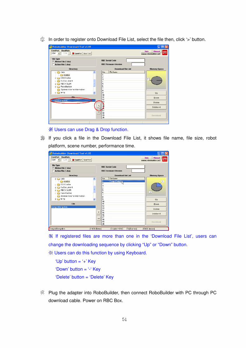
⑨ In order to register onto Download File List, select the file then, click ‘>’ button.
※ Users can use Drag & Drop function. ⑩ If you click a file in the Download File List, it shows file name, file size, robot
platform, scene number, performance time.
※ If registered files are more than one in the ‘Download File List’, users can
change the downloading sequence by clicking “Up” or “Down” button. ※ Users can do this function by using Keyboard.
‘Up’ button = ‘+’ Key
‘Down’ button = ‘-‘ Key
‘Delete’ button = ‘Delete’ Key
⑪ Plug the adapter into RoboBuilder, then connect RoboBuilder with PC through PC
download cable. Power on RBC Box.

52
⑫ Click ‘ScanPort’ button in order to find available COM Port.
⑬ RBC serial code and Firmware Version will be shown if connected properly. And
“ClosePort” button will be shown as well.
⑭ Click ‘Download” button, in order to all files in the “Download File List”. Then it
starts downloading into RBC Box. Following message box will shown after
downloaded completely.

53
54
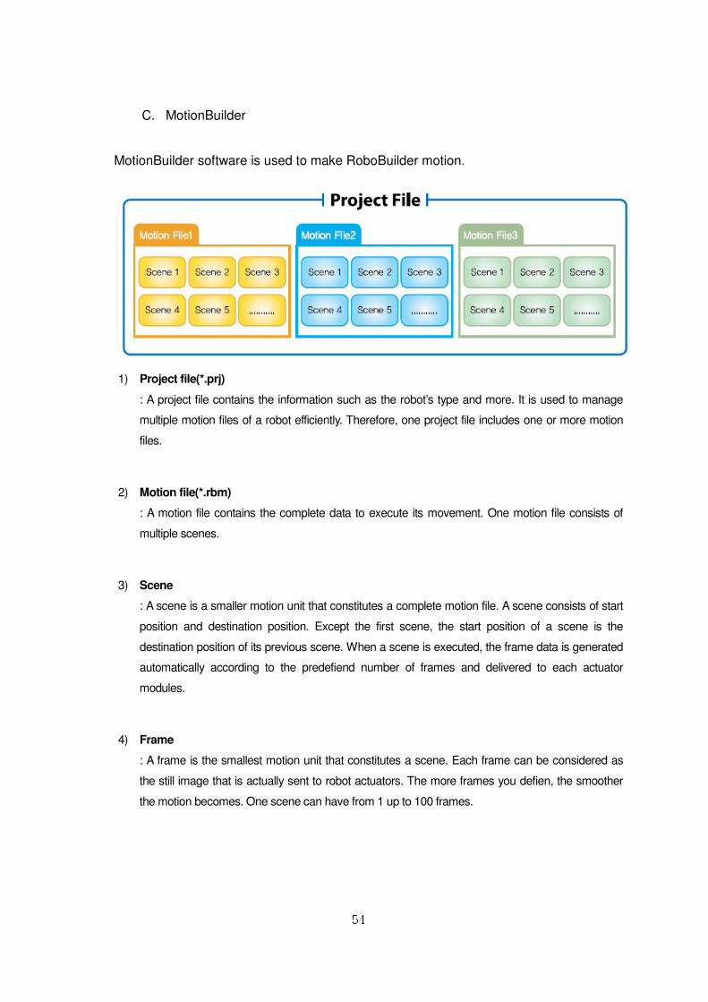
C. MotionBuilder
MotionBuilder software is used to make RoboBuilder motion.
1) Project file(*.prj)
: A project file contains the information such as the robot’s type and more. It is used to manage
multiple motion files of a robot efficiently. Therefore, one project file includes one or more motion
files.
2) Motion file(*.rbm)
: A motion file contains the complete data to execute its movement. One motion file consists of
multiple scenes.
3) Scene
: A scene is a smaller motion unit that constitutes a complete motion file. A scene consists of start
position and destination position. Except the first scene, the start position of a scene is the
destination position of its previous scene. When a scene is executed, the frame data is generated
automatically according to the predefiend number of frames and delivered to each actuator
modules.
4) Frame
: A frame is the smallest motion unit that constitutes a scene. Each frame can be considered as
the still image that is actually sent to robot actuators. The more frames you defien, the smoother
the motion becomes. One scene can have from 1 up to 100 frames.
55
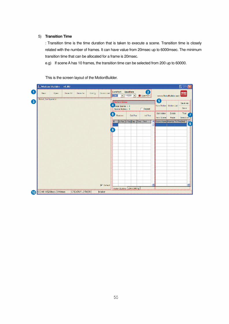
5) Transition Time
: Transition time is the time duration that is taken to execute a scene. Transition time is closely
related with the number of frames. It can have value from 20msec up to 6000msec. The minimum
transition time that can be allocated for a frame is 20msec.
e.g) If scene A has 10 frames, the transition time can be selected from 200 up to 60000.
This is the screen layout of the MotionBuilder.

56
57
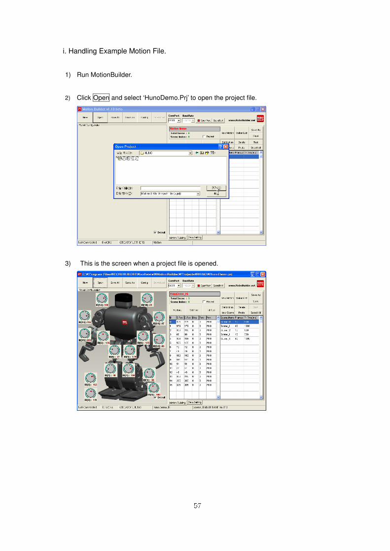
i. Handling Example Motion File.
1) Run MotionBuilder.
2) Click Open and select ‘HunoDemo.Prj’ to open the project file.
3) This is the screen when a project file is opened.
58
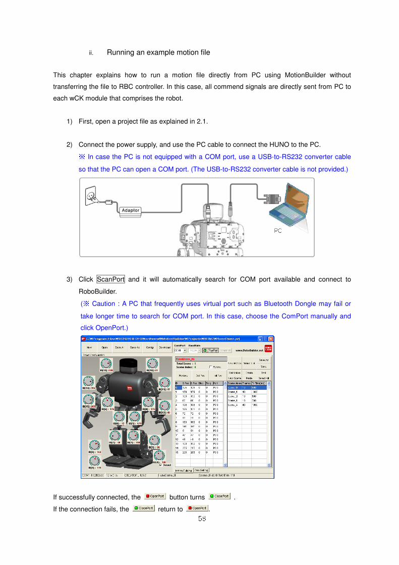
ii. Running an example motion file
This chapter explains how to run a motion file directly from PC using MotionBuilder without
transferring the file to RBC controller. In this case, all commend signals are directly sent from PC to
each wCK module that comprises the robot.
1) First, open a project file as explained in 2.1.
2) Connect the power supply, and use the PC cable to connect the HUNO to the PC. ※ In case the PC is not equipped with a COM port, use a USB-to-RS232 converter cable
so that the PC can open a COM port. (The USB-to-RS232 converter cable is not provided.)
3) Click ScanPort and it will automatically search for COM port available and connect to
RoboBuilder.
(※ Caution : A PC that frequently uses virtual port such as Bluetooth Dongle may fail or
take longer time to search for COM port. In this case, choose the ComPort manually and
click OpenPort.)
If successfully connected, the button turns .
If the connection fails, the return to .
59
Usual causes of the failure are as follow.
a. When the PC cable is unplugged
b. When the driver for USB-to-RS232 converter is not installed correctly
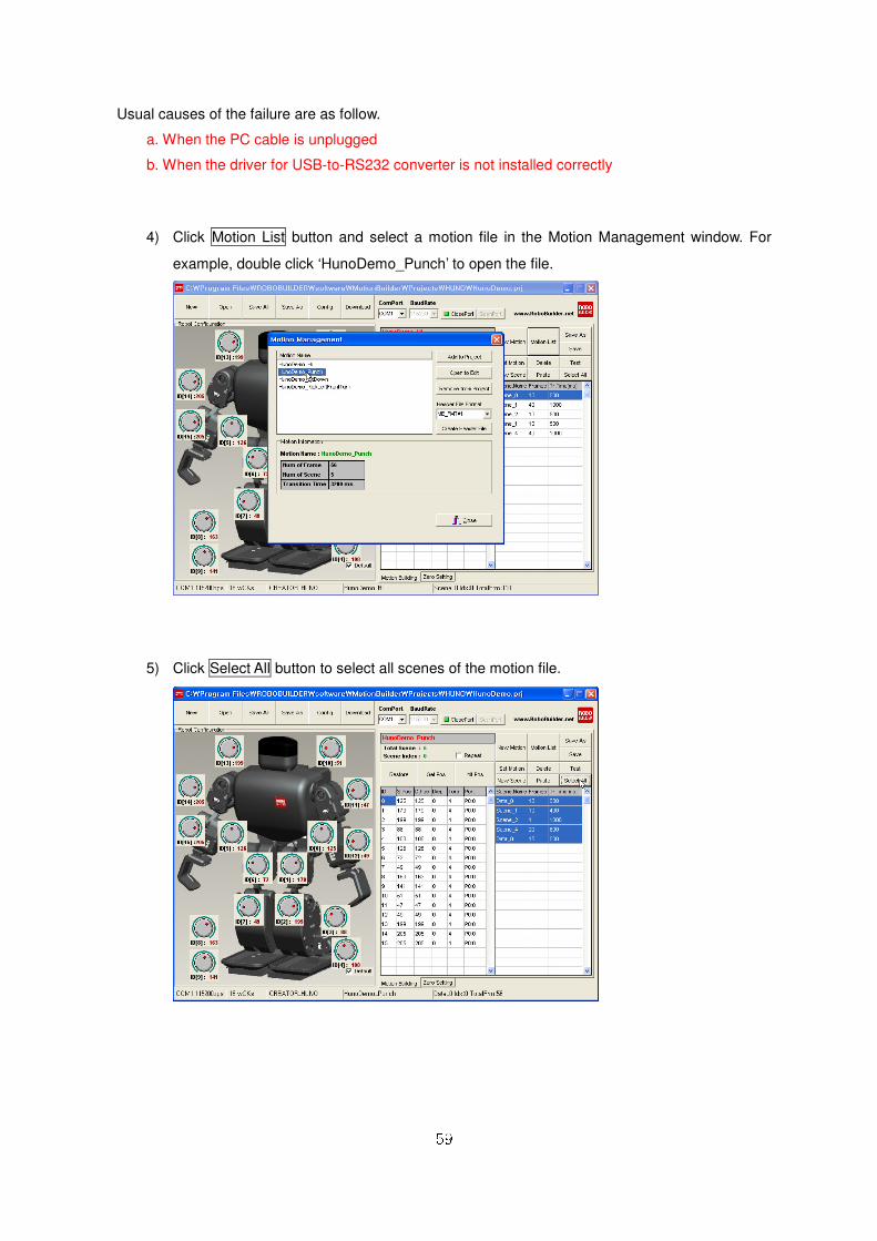
4) Click Motion List button and select a motion file in the Motion Management window. For
example, double click ‘HunoDemo_Punch’ to open the file.
5) Click Select All button to select all scenes of the motion file.
60
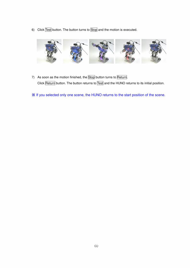
6) Click Test button. The button turns to Stop and the motion is executed.
7) As soon as the motion finished, the Stop button turns to Return.
Click Return button. The button returns to Test and the HUNO returns to its initial position.
※ If you selected only one scene, the HUNO returns to the start position of the scene.
61
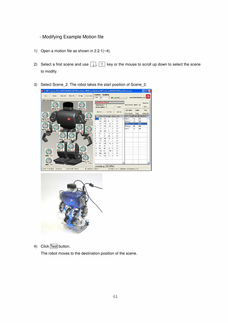
- Modifying Example Motion file
1) Open a motion file as shown in 2.2 1)~4).
2) Select a first scene and use ↓ , ↑ key or the mouse to scroll up down to select the scene
to modify.
3) Select Scene_2. The robot takes the start position of Scene_2.
4) Click Test button.
The robot moves to the destination position of the scene.
62
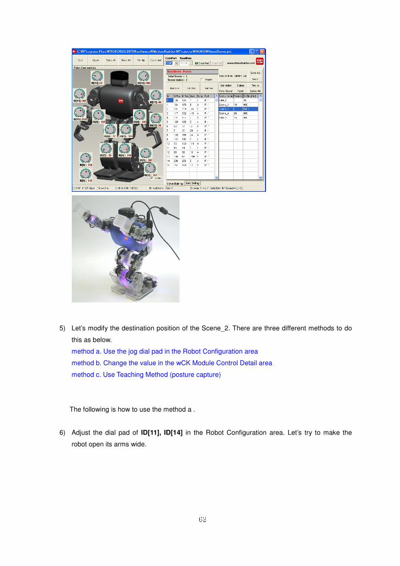
5) Let’s modify the destination position of the Scene_2. There are three different methods to do
this as below.
method a. Use the jog dial pad in the Robot Configuration area
method b. Change the value in the wCK Module Control Detail area
method c. Use Teaching Method (posture capture)
The following is how to use the method a .
6) Adjust the dial pad of ID[11], ID[14] in the Robot Configuration area. Let’s try to make the
robot open its arms wide.
63
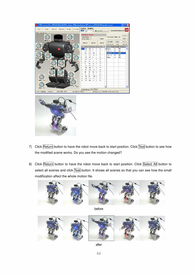
7) Click Return button to have the robot move back to start position. Click Test button to see how
the modified scene works. Do you see the motion changed?
8) Click Return button to have the robot move back to start position. Click Select All button to
select all scenes and click Test button. It shows all scenes so that you can see how the small
modification affect the whole motion file.
before
after

64
- ActionBuilder
“Action” is the robot’s action that has certain purpose, and Action Builder is the software that can
create, edit, save and download the Action files.
a. Screen Layout
① Menu Bar
. New : creates a new action file.
. Open : opens an existing action file (*.rba).
. Save : saves the running action file.
. Save As : saves the running action file as a different name.
. Config : configures the file properties.
. Download : transfers an action file to the control box.
② PC Port Connection
. ComPort : sets the port on PC to connect the robot with.
. BaudRate : sets the data communication speed (default:115,200kbps).
. OpenPort : opens the set PC port to connect the robot with.
. ScanPort : scans, finds, and opens the PC port connected with the robot automatically.
③ Action File Information
. Action Name : displays the name of the action file currently running.
. Robot Platform : displays the robot platform type on which the action file will be played.
. Total Statements : displays the number of statements in the action file. ④ Statement List
. Index : displays the index number of the statement.
. St. Name : displays the name of the statement.
65
. Condition : displays the condition part of the statement.
. Execution : displays the execution part of the statement.
. Description : displays the description of the statement.
⑤ Statement Editing
. Statement Name : displays the statement name. It is also used to type in the name for the
statement.
. Description : displays the description of the statement. It is also used to type in the
description for the statement.
. Add : add a new statement in the action file.
. Delete : delete the selected statement from the action file.
. Update : update the change to the statement.
⑥ Conditions[if]
. None : no condition
. Distance : condition of visual distance detection
. Sound In : condition of sound detection
. Button : condition of the buttons on the control box
. Remocon : condition of inputs from remote controller
[IR remote control, compatible joystick etc]
. Accel. : X, Y, Z axis acceleration
⑦ Executions[then]
. None : no execution
. Motion Out : play the selected motion file.
. Sound Out : play the selected sound source.
. Wait Time : wait for the specified amount of time [in millisecond].
. Jump Index : jumps to the statement of specified index number.
※ Please refer to the Action file programming by using Action Builder in chapter.
66
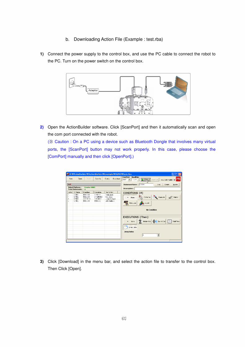
b. Downloading Action File (Example : test.rba)
1) Connect the power supply to the control box, and use the PC cable to connect the robot to
the PC. Turn on the power switch on the control box.
2) Open the ActionBuilder software. Click [ScanPort] and then it automatically scan and open
the com port connected with the robot.
(※ Caution : On a PC using a device such as Bluetooth Dongle that involves many virtual
ports, the [ScanPort] button may not work properly. In this case, please choose the
[ComPort] manually and then click [OpenPort].)
3) Click [Download] in the menu bar, and select the action file to transfer to the control box.
Then Click [Open].
67
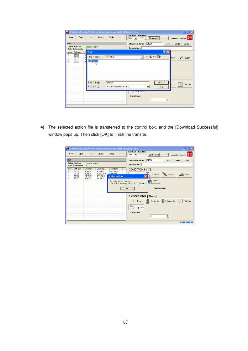
4) The selected action file is transferred to the control box, and the [Download Successful]
window pops up. Then click [OK] to finish the transfer.
68
5) In order to play the transferred action file, first click [ClosePort] to disconnect the robot from
comport. Use the remote controller to press and hold the button # and then press the numeric button
(1~0) together. For example, the first action file is played when you press # button and 1 button
together. If you want to stop the action file, turn off the power.
※※※※ NOTE
1. Once file transfer begins, all action files already existing in the control box are deleted and the
new files overwrite from the beginning of the ROM memory. The first file transferred is assigned to
the button 1 of the remote controller, the second file transferred is assigned to button 2, and the third
file to button 3 and so on. Therefore, you have to plan and decide which action file to assign to
which button before you actually start transferring the files.
2. When you transfer action files, the motion files are not affected.
3. If the size of a particular action file is too large, the RBC is NOT able to save up to 10 action files.
4. The control box firmware has to be upgraded up ver. 2.0 or above in order to use the Action
Builder.
69
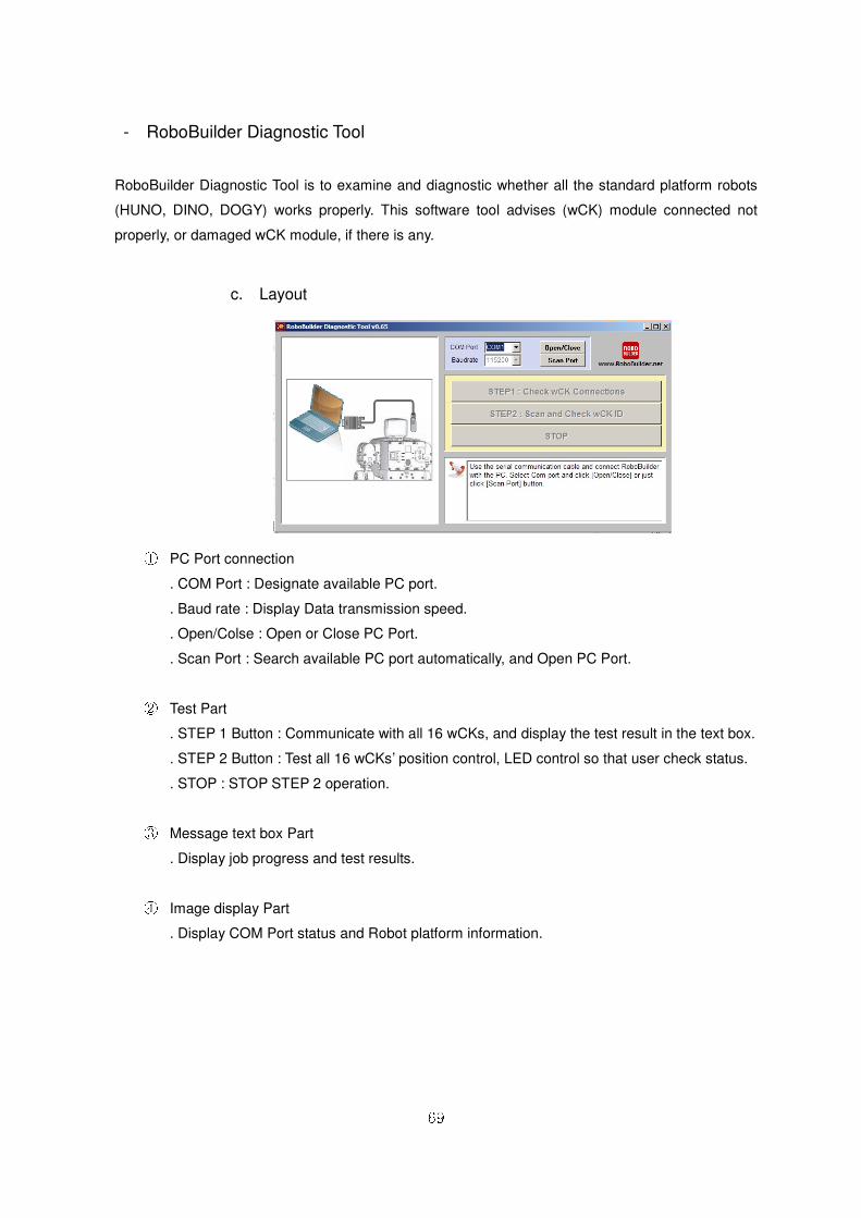
- RoboBuilder Diagnostic Tool
RoboBuilder Diagnostic Tool is to examine and diagnostic whether all the standard platform robots
(HUNO, DINO, DOGY) works properly. This software tool advises (wCK) module connected not
properly, or damaged wCK module, if there is any.
c. Layout
① PC Port connection
. COM Port : Designate available PC port.
. Baud rate : Display Data transmission speed.
. Open/Colse : Open or Close PC Port.
. Scan Port : Search available PC port automatically, and Open PC Port.
② Test Part
. STEP 1 Button : Communicate with all 16 wCKs, and display the test result in the text box.
. STEP 2 Button : Test all 16 wCKs’ position control, LED control so that user check status.
. STOP : STOP STEP 2 operation.
③ Message text box Part
. Display job progress and test results.
④ Image display Part
. Display COM Port status and Robot platform information.
70
55..22 MMSSRRDDSS SSooffttwwaarree
AA.. MMSSRRDDSS IInnssttaallllaattiioonn
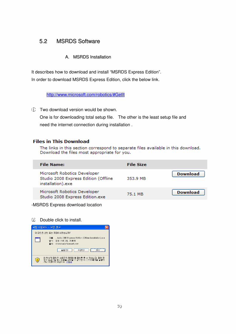
It describes how to download and install “MSRDS Express Edition”.
In order to download MSRDS Express Edition, click the below link.
http://www.microsoft.com/robotics/#GetIt
① Two download version would be shown.
One is for downloading total setup file. The other is the least setup file and
need the internet connection during installation .
-MSRDS Express download location
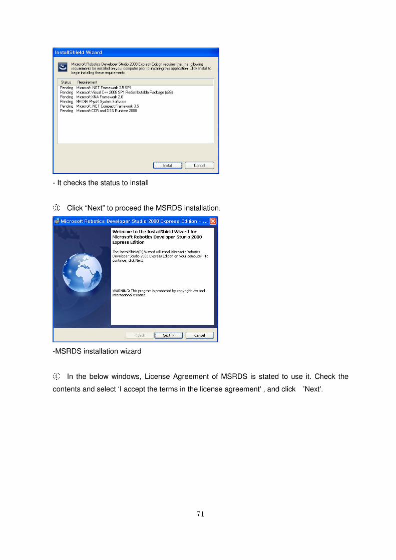
② Double click to install.
71
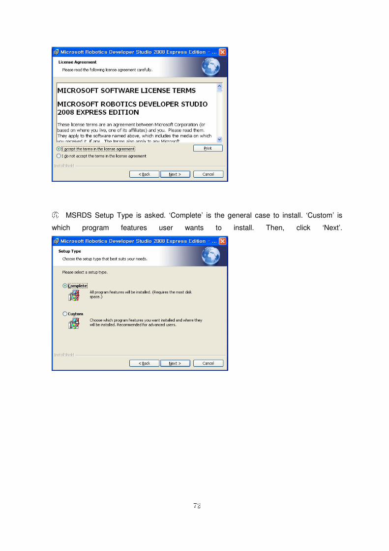
- It checks the status to install
③ Click “Next” to proceed the MSRDS installation.
-MSRDS installation wizard
④ In the below windows, License Agreement of MSRDS is stated to use it. Check the
contents and select ‘I accept the terms in the license agreement' , and click ’Next'.
72
⑤ MSRDS Setup Type is asked. ‘Complete’ is the general case to install. ‘Custom’ is
which program features user wants to install. Then, click ‘Next’.

73
⑥ Click “Install” to proceed.
⑦ If setup is finished MSRDS, check ‘Yes, I want to restart my computer now', then,
click “Finish”.
- Setup finished
74
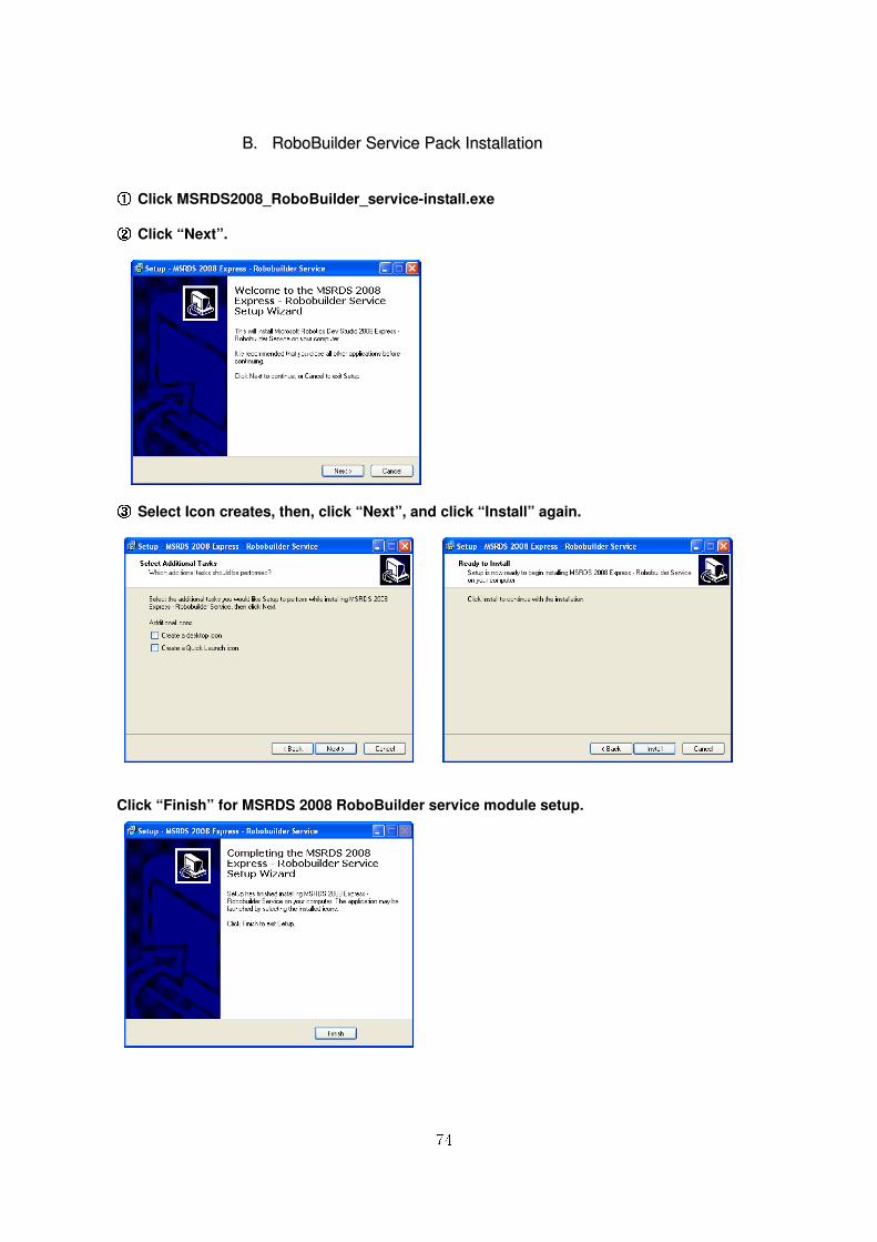
BB.. RRoobbooBBuuiillddeerr SSeerrvviiccee PPaacckk IInnssttaallllaattiioonn
①①①① Click MSRDS2008_RoboBuilder_service-install.exe ②②②② Click “Next”.
③③③③ Select Icon creates, then, click “Next”, and click “Install” again.
Click “Finish” for MSRDS 2008 RoboBuilder service module setup.
75
66.. MMSSRRDDSS -- VVPPLL DDeevveellooppmmeenntt EEnnvviirroonnmmeenntt
66..11 OOvveerrvviieeww
VPL is GUI based programming environment and can develop various Robot application.
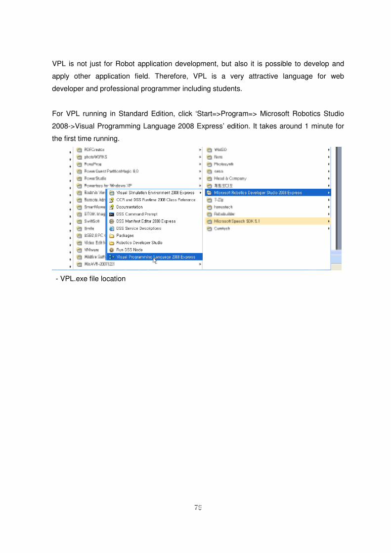
Also, it provides multitask process environment, that can process various task
simultaneously. By this reason, it is suitable for large size application system.
- VPL programming example
76
VPL is not just for Robot application development, but also it is possible to develop and
apply other application field. Therefore, VPL is a very attractive language for web
developer and professional programmer including students.
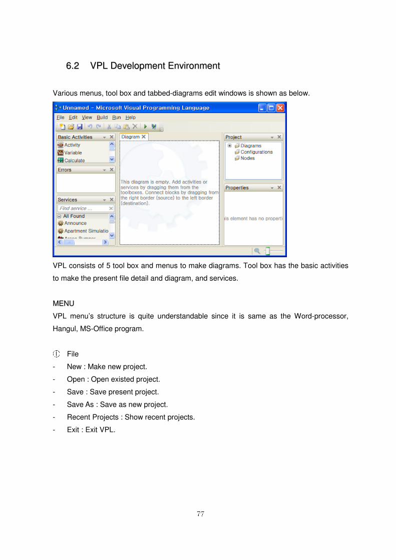
For VPL running in Standard Edition, click ‘Start=>Program=> Microsoft Robotics Studio
2008->Visual Programming Language 2008 Express’ edition. It takes around 1 minute for
the first time running.
- VPL.exe file location
77
66..22 VVPPLL DDeevveellooppmmeenntt EEnnvviirroonnmmeenntt
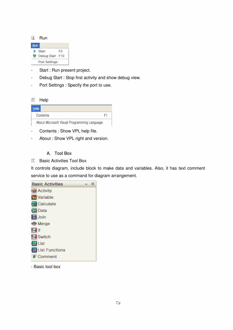
Various menus, tool box and tabbed-diagrams edit windows is shown as below.
VPL consists of 5 tool box and menus to make diagrams. Tool box has the basic activities
to make the present file detail and diagram, and services.
MMEENNUU
VPL menu’s structure is quite understandable since it is same as the Word-processor,
Hangul, MS-Office program.
① File
- New : Make new project.
- Open : Open existed project.
- Save : Save present project.
- Save As : Save as new project.
- Recent Projects : Show recent projects.
- Exit : Exit VPL.

78
② Edit
- Actions and Notifications : Show service action or, alert dialogue window
- Define Variables : Show variables definition dialogue window
- Connections : Show two block connection edit dialogue window
- Data Connections : Show data connection edit dialogue window
- Set Configuration : Show service or partner configuration panel.
③ View
- Toolboxes : Show/Hide Basic activity, Service, Project and Property
- Grid : Show/Hide Grid for diagram
- Toolbar : Show/Hide VPL tool bar
79
④ Run
- Start : Run present project.
- Debug Start : Stop first activity and show debug view.
- Port Settings : Specify the port to use.
⑤ Help
- Contents : Show VPL help file.
- About : Show VPL right and version.
AA.. TTooooll BBooxx ① Basic Activities Tool Box
It controls diagram, include block to make data and variables. Also, it has text comment
service to use as a command for diagram arrangement.
- Basic tool box
80
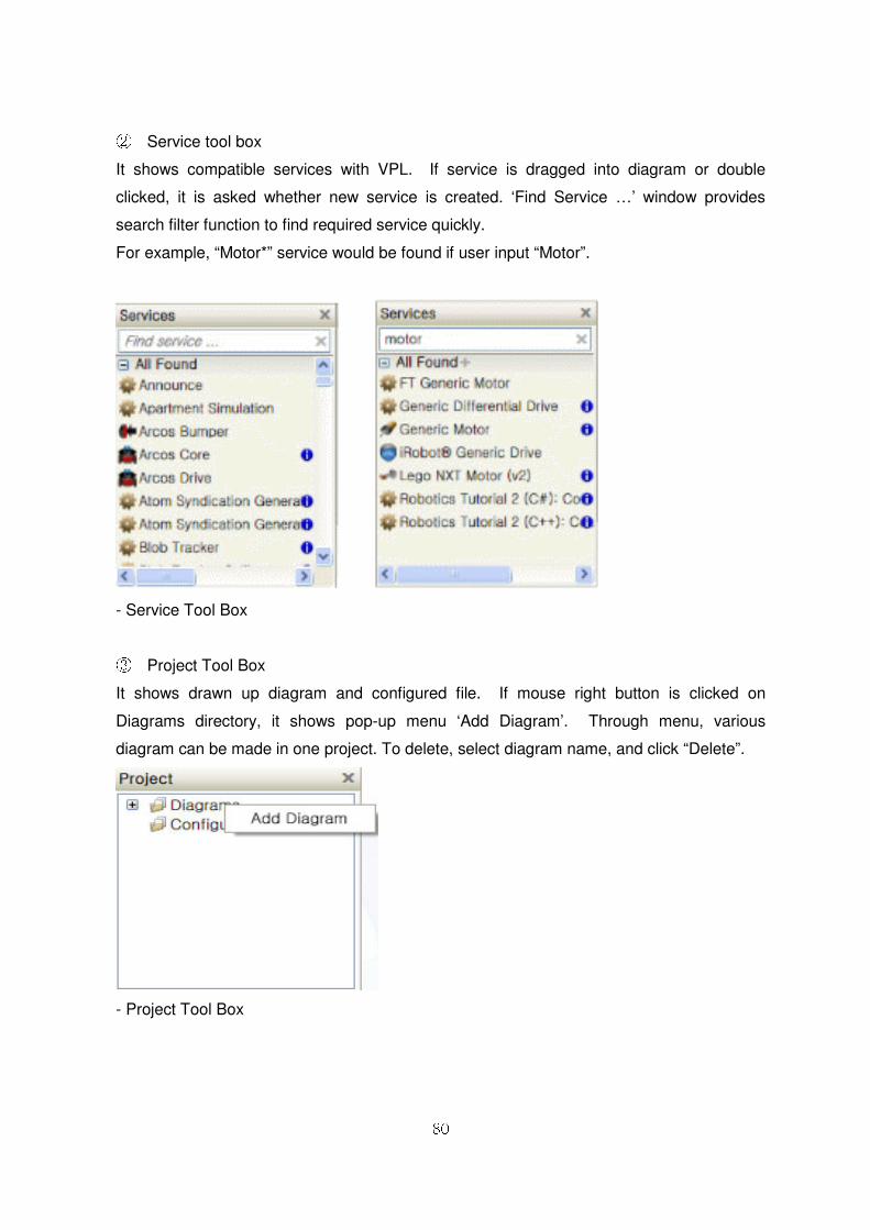
② Service tool box
It shows compatible services with VPL. If service is dragged into diagram or double
clicked, it is asked whether new service is created. ‘Find Service …’ window provides
search filter function to find required service quickly.
For example, “Motor*” service would be found if user input “Motor”.
- Service Tool Box
③ Project Tool Box
It shows drawn up diagram and configured file. If mouse right button is clicked on
Diagrams directory, it shows pop-up menu ‘Add Diagram’. Through menu, various
diagram can be made in one project. To delete, select diagram name, and click “Delete”.
- Project Tool Box

81
To close the edit window, click “x” button. To open it, Double-click diagram to be opened.
④ Property tool box
It shows the property of selected block, connection line, diagrams. In case of block, it is
possible to show and change input/output and range. Also, it could designate initial status,
or connect manifest. Below is Property tool box example in accordance with tasks.
- Property Tool Box
82
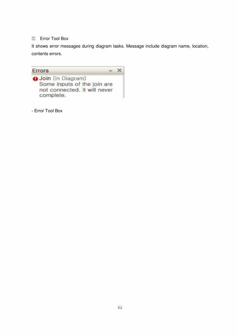
⑤ Error Tool Box
It shows error messages during diagram tasks. Message include diagram name, location,
contents errors.
- Error Tool Box
83
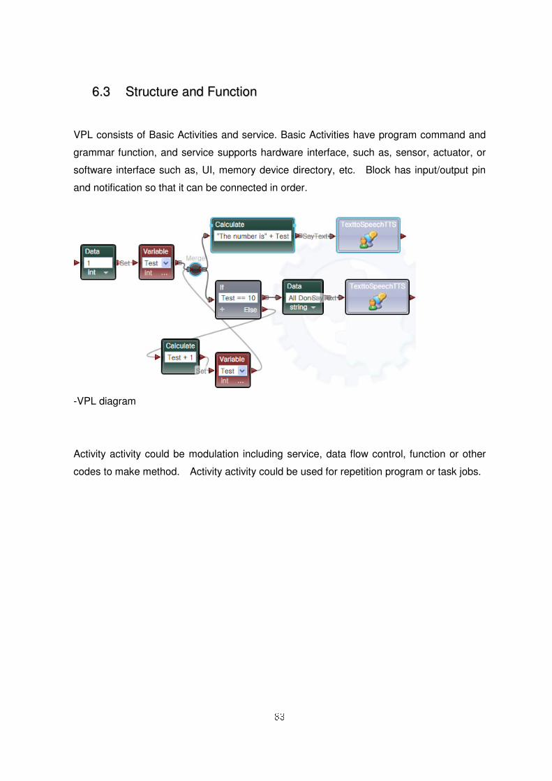
66..33 SSttrruuccttuurree aanndd FFuunnccttiioonn
VPL consists of Basic Activities and service. Basic Activities have program command and
grammar function, and service supports hardware interface, such as, sensor, actuator, or
software interface such as, UI, memory device directory, etc. Block has input/output pin
and notification so that it can be connected in order.
-VPL diagram
Activity activity could be modulation including service, data flow control, function or other
codes to make method. Activity activity could be used for repetition program or task jobs.
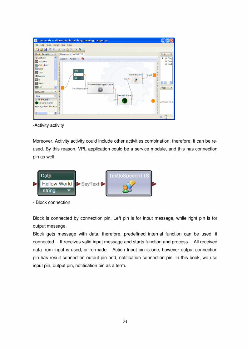
84
-Activity activity
Moreover, Activity activity could include other activities combination, therefore, it can be re-
used. By this reason, VPL application could be a service module, and this has connection
pin as well.
- Block connection
Block is connected by connection pin. Left pin is for input message, while right pin is for
output message.
Block gets message with data, therefore, predefined internal function can be used, if
connected. It receives valid input message and starts function and process. All received
data from input is used, or re-made. Action Input pin is one, however output connection
pin has result connection output pin and, notification connection pin. In this book, we use
input pin, output pin, notification pin as a term.
85
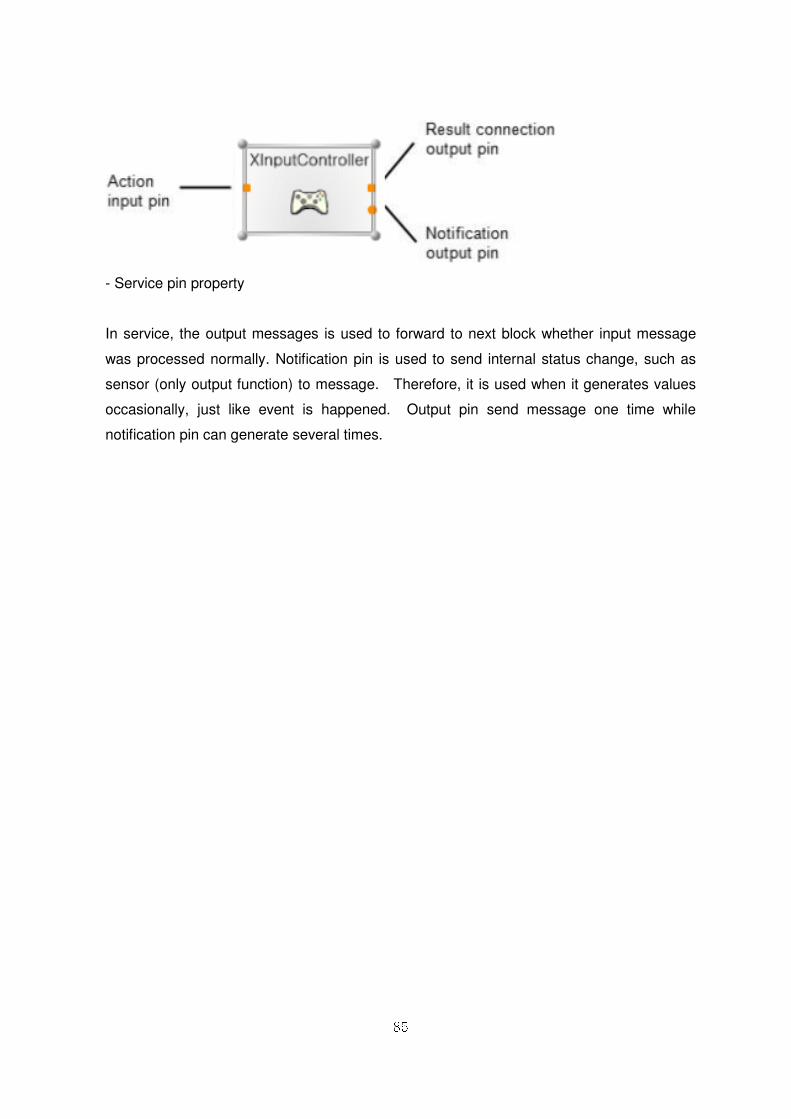
- Service pin property
In service, the output messages is used to forward to next block whether input message
was processed normally. Notification pin is used to send internal status change, such as
sensor (only output function) to message. Therefore, it is used when it generates values
occasionally, just like event is happened. Output pin send message one time while
notification pin can generate several times.
86
77.. VVPPLL -- BBaassiicc AAccttiivviittiieess
VPL includes various Activities in Basic Activities to create diagram.
This activity is generally used to link between services, or it can be linked with these
activities.
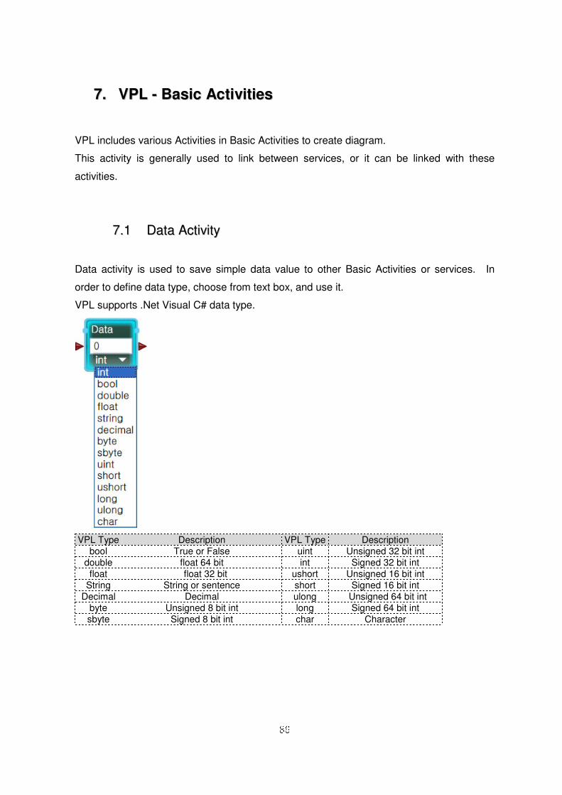
77..11 DDaattaa AAccttiivviittyy
Data activity is used to save simple data value to other Basic Activities or services. In
order to define data type, choose from text box, and use it.
VPL supports .Net Visual C# data type.
VPL Type Description VPL Type Description bool True or False uint Unsigned 32 bit int
double float 64 bit int Signed 32 bit int float float 32 bit ushort Unsigned 16 bit int
String String or sentence short Signed 16 bit int Decimal Decimal ulong Unsigned 64 bit int
byte Unsigned 8 bit int long Signed 64 bit int sbyte Signed 8 bit int char Character
87
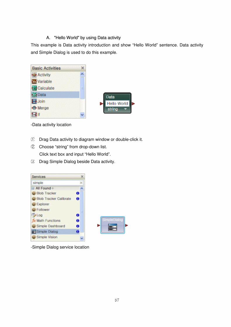
AA.. ""HHeelllloo WWoorrlldd"" bbyy uussiinngg DDaattaa aaccttiivviittyy
This example is Data activity introduction and show “Hello World” sentence. Data activity
and Simple Dialog is used to do this example.
-Data activity location
① Drag Data activity to diagram window or double-click it. ② Choose “string” from drop-down list.
Click text box and input “Hello World”. ③ Drag Simple Dialog beside Data activity.
-Simple Dialog service location
88
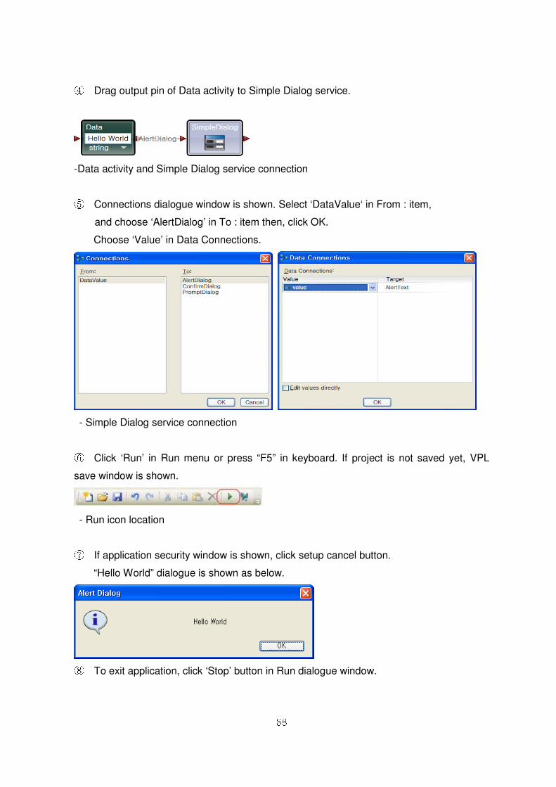
④ Drag output pin of Data activity to Simple Dialog service.
-Data activity and Simple Dialog service connection
⑤ Connections dialogue window is shown. Select ‘DataValue‘ in From : item,
and choose ‘AlertDialog’ in To : item then, click OK.
Choose ‘Value’ in Data Connections.
- Simple Dialog service connection
⑥ Click ‘Run’ in Run menu or press “F5” in keyboard. If project is not saved yet, VPL
save window is shown.
- Run icon location
⑦ If application security window is shown, click setup cancel button.
“Hello World” dialogue is shown as below.
⑧ To exit application, click ‘Stop’ button in Run dialogue window.
89
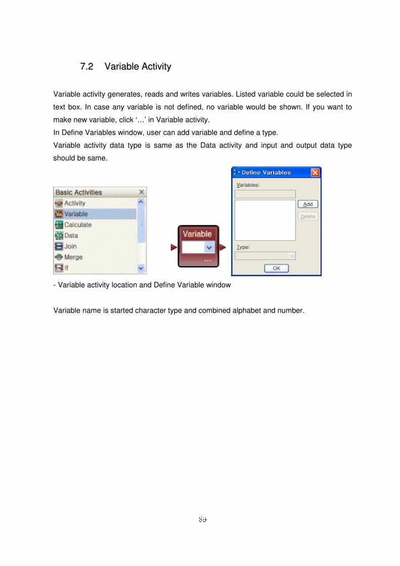
77..22 VVaarriiaabbllee AAccttiivviittyy
Variable activity generates, reads and writes variables. Listed variable could be selected in
text box. In case any variable is not defined, no variable would be shown. If you want to
make new variable, click ‘…’ in Variable activity.
In Define Variables window, user can add variable and define a type.
Variable activity data type is same as the Data activity and input and output data type
should be same.
- Variable activity location and Define Variable window
Variable name is started character type and combined alphabet and number.
90
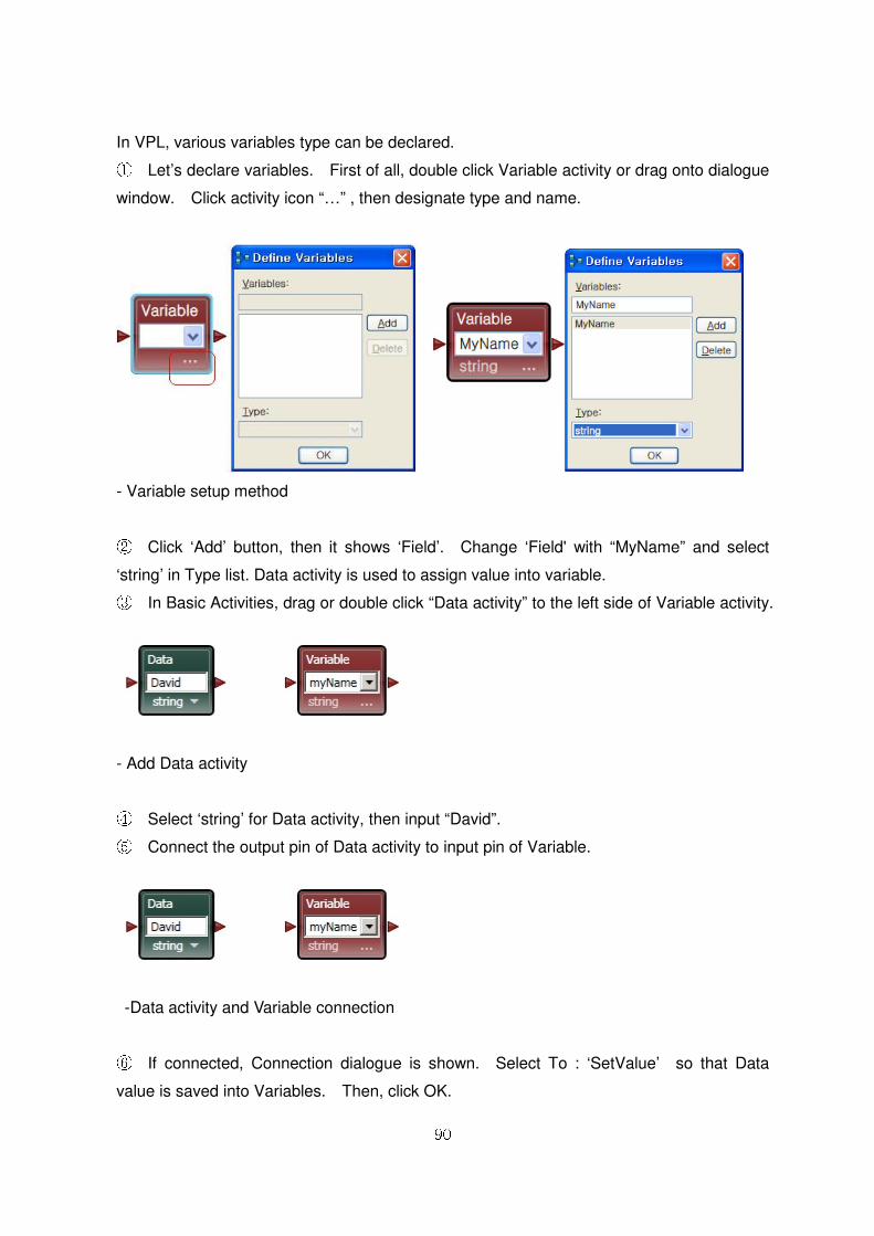
In VPL, various variables type can be declared. ① Let’s declare variables. First of all, double click Variable activity or drag onto dialogue
window. Click activity icon “…” , then designate type and name.
- Variable setup method
② Click ‘Add’ button, then it shows ‘Field’. Change ‘Field' with “MyName” and select
‘string’ in Type list. Data activity is used to assign value into variable. ③ In Basic Activities, drag or double click “Data activity” to the left side of Variable activity.
- Add Data activity
④ Select ‘string’ for Data activity, then input “David”. ⑤ Connect the output pin of Data activity to input pin of Variable.
-Data activity and Variable connection
⑥ If connected, Connection dialogue is shown. Select To : ‘SetValue’ so that Data
value is saved into Variables. Then, click OK.
91
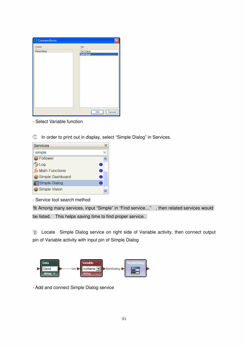
- Select Variable function
⑦ In order to print out in display, select “Simple Dialog” in Services.
- Service tool search method ※ Among many services, input “Simple” in “Find service…” , then related services would
be listed. This helps saving time to find proper service.
⑧ Locate Simple Dialog service on right side of Variable activity, then connect output
pin of Variable activity with input pin of Simple Dialog
- Add and connect Simple Dialog service
92
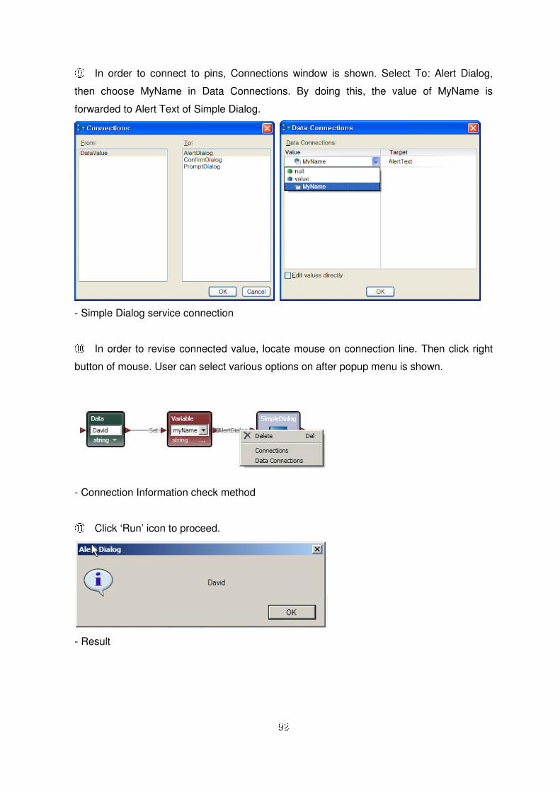
⑨ In order to connect to pins, Connections window is shown. Select To: Alert Dialog,
then choose MyName in Data Connections. By doing this, the value of MyName is
forwarded to Alert Text of Simple Dialog.
- Simple Dialog service connection
⑩ In order to revise connected value, locate mouse on connection line. Then click right
button of mouse. User can select various options on after popup menu is shown.
- Connection Information check method
⑪ Click ‘Run’ icon to proceed.
- Result
93
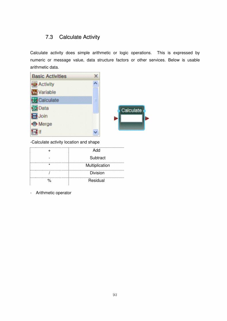
77..33 CCaallccuullaattee AAccttiivviittyy
Calculate activity does simple arithmetic or logic operations. This is expressed by
numeric or message value, data structure factors or other services. Below is usable
arithmetic data.
-Calculate activity location and shape
- Arithmetic operator
+ Add
- Subtract
* Multiplication
/ Division
% Residual
94
Plus (+) operator is also used to connect strings. This also can combine string and
numeric. (Ex. “The answer is ”+ x/4)
&& AND
|| OR
! NOT
- Logic operator
In accordance with round bracket mark, priority is decided. Click Calculate text box, then it shows
input message, data structure and pre-defined value list.
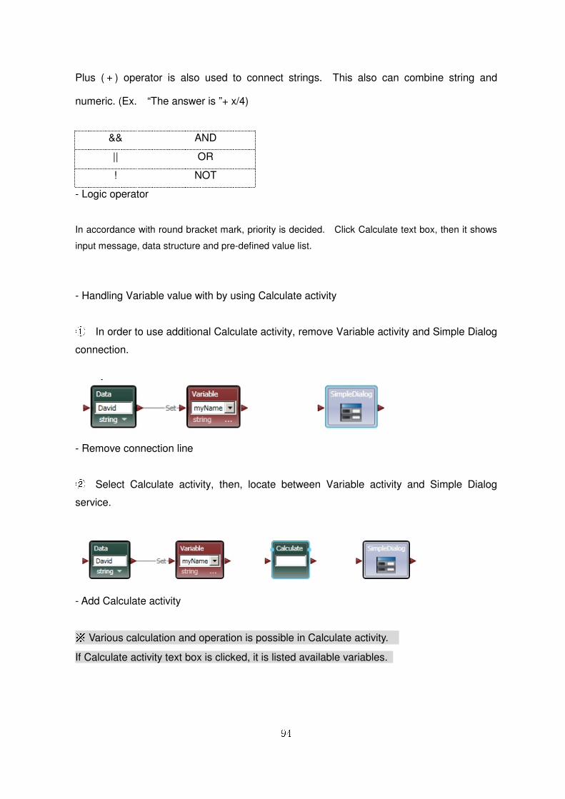
- Handling Variable value with by using Calculate activity
① In order to use additional Calculate activity, remove Variable activity and Simple Dialog
connection.
- Remove connection line
② Select Calculate activity, then, locate between Variable activity and Simple Dialog
service.
- Add Calculate activity
※ Various calculation and operation is possible in Calculate activity.
If Calculate activity text box is clicked, it is listed available variables.
95
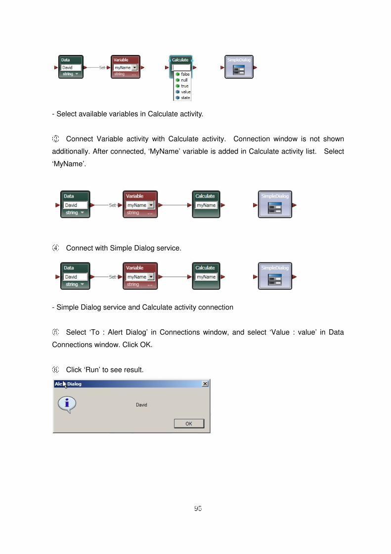
- Select available variables in Calculate activity.
③ Connect Variable activity with Calculate activity. Connection window is not shown
additionally. After connected, ‘MyName’ variable is added in Calculate activity list. Select
‘MyName’.
④ Connect with Simple Dialog service.
- Simple Dialog service and Calculate activity connection
⑤ Select ‘To : Alert Dialog’ in Connections window, and select ‘Value : value’ in Data
Connections window. Click OK.
⑥ Click ‘Run’ to see result.
96
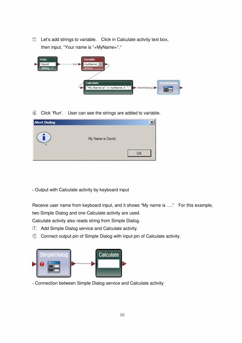
⑦ Let’s add strings to variable. Click in Calculate activity text box,
then input, “Your name is ”+MyName+".“
⑧ Click ‘Run’. User can see the strings are added to variable.
- Output with Calculate activity by keyboard input
Receive user name from keyboard input, and it shows “My name is ….” For this example,
two Simple Dialog and one Calculate activity are used.
Calculate activity also reads string from Simple Dialog. ① Add Simple Dialog service and Calculate activity. ② Connect output pin of Simple Dialog with input pin of Calculate activity.
- Connection between Simple Dialog service and Calculate activity

97
③ Select ‘From : Prompt Dialog–SuccessConnections’ in Connections window. Prompt
Dialog is used to receive keyboard input. SimpleDialog input is not need because of
keyboard input.
④ After connected, available values are listed when Calculate activity text box is clicked.
Select ‘Text Data’ in Simple Dialog.
⑤ Drag another Simple Dialog service onto diagram edit window. ⑥ This project already includes this activity. Therefore, it is asked whether to create a
new instance or use an existing one.

98
⑦ In this example, same Simple Dialog service should be used, therefore, select second
“SimpleDialog”, then click OK. In diagram edit window, same activity name is added.
⑧ In diagram two Simple Dialog service are shown. Actually, existed SimpleDialog is re-
used and only one activity is running for this project.
⑨ After block added, connect output pin of Calculate activity with input pin of Simple
Dialog.
⑩ Select “To : Alert Dialog” in Connections window, and select “Value : value in Data
Connections window. Click to run this project.
Input “Test” .
- Keyboard input by using Prompt Dialog
99
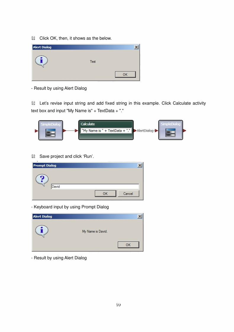
⑪ Click OK, then, it shows as the below.
- Result by using Alert Dialog
⑫ Let’s revise input string and add fixed string in this example. Click Calculate activity
text box and input "My Name is" + TextData + "."
⑬ Save project and click ‘Run’.
- Keyboard input by using Prompt Dialog
- Result by using Alert Dialog
100
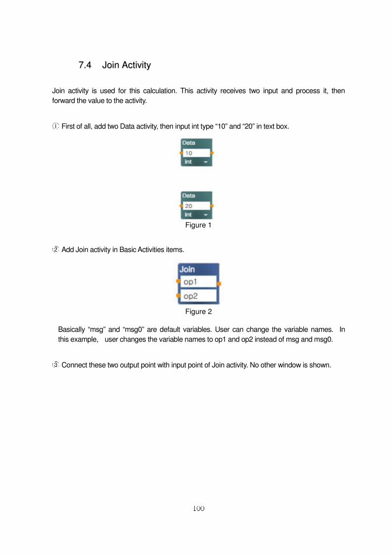
77..44 JJooiinn AAccttiivviittyy
Join activity is used for this calculation. This activity receives two input and process it, then
forward the value to the activity.
① First of all, add two Data activity, then input int type “10” and “20” in text box.
Figure 1
② Add Join activity in Basic Activities items.
Figure 2
Basically “msg” and “msg0” are default variables. User can change the variable names. In
this example, user changes the variable names to op1 and op2 instead of msg and msg0.
③ Connect these two output point with input point of Join activity. No other window is shown.
101
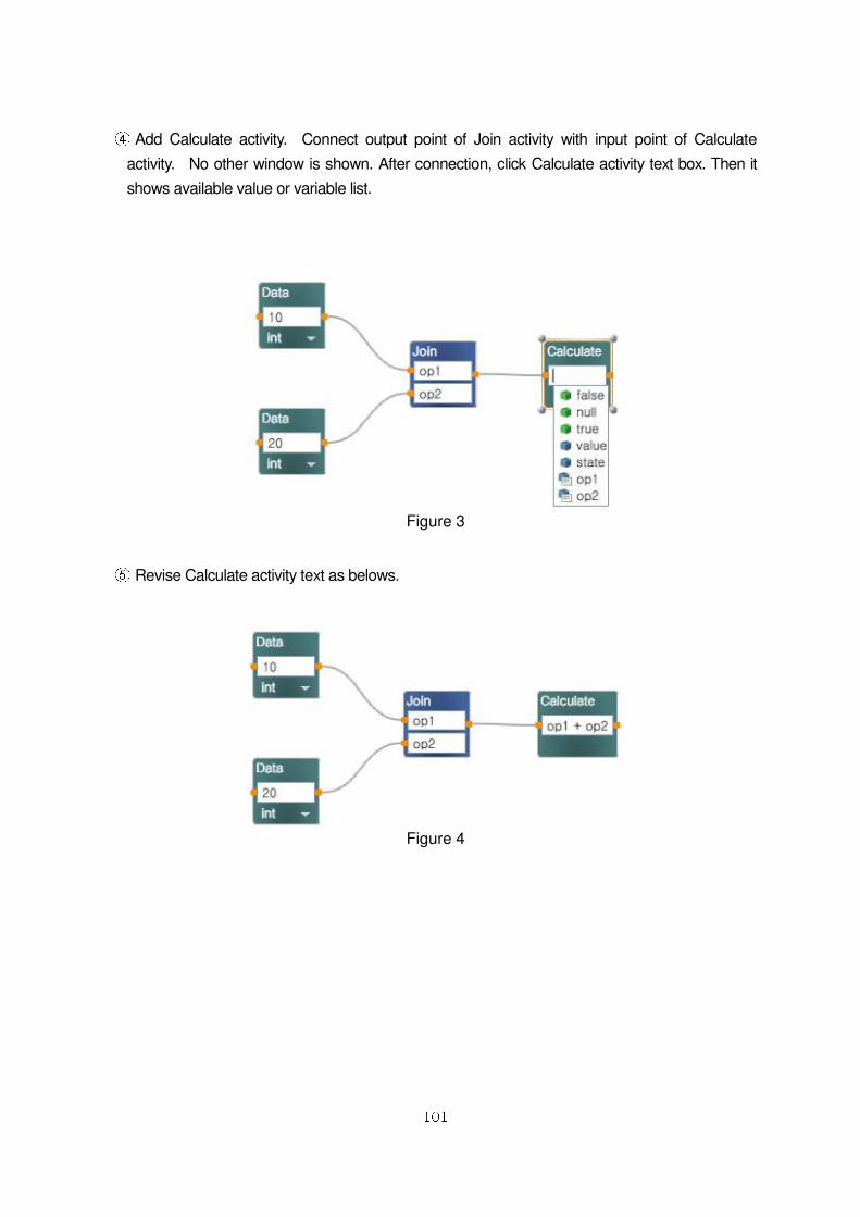
④ Add Calculate activity. Connect output point of Join activity with input point of Calculate
activity. No other window is shown. After connection, click Calculate activity text box. Then it
shows available value or variable list.
Figure 3
⑤ Revise Calculate activity text as belows.
Figure 4

102
⑥ After adding SimpleDialog activity, connect the output point of Calculate activity with input
point of Simple Dialog activity. At this time, Connections window is shown. Select AlertDialog.
Figure 5 ⑦ Select “Value-value “ in Data Connections window.
Figure 6
103
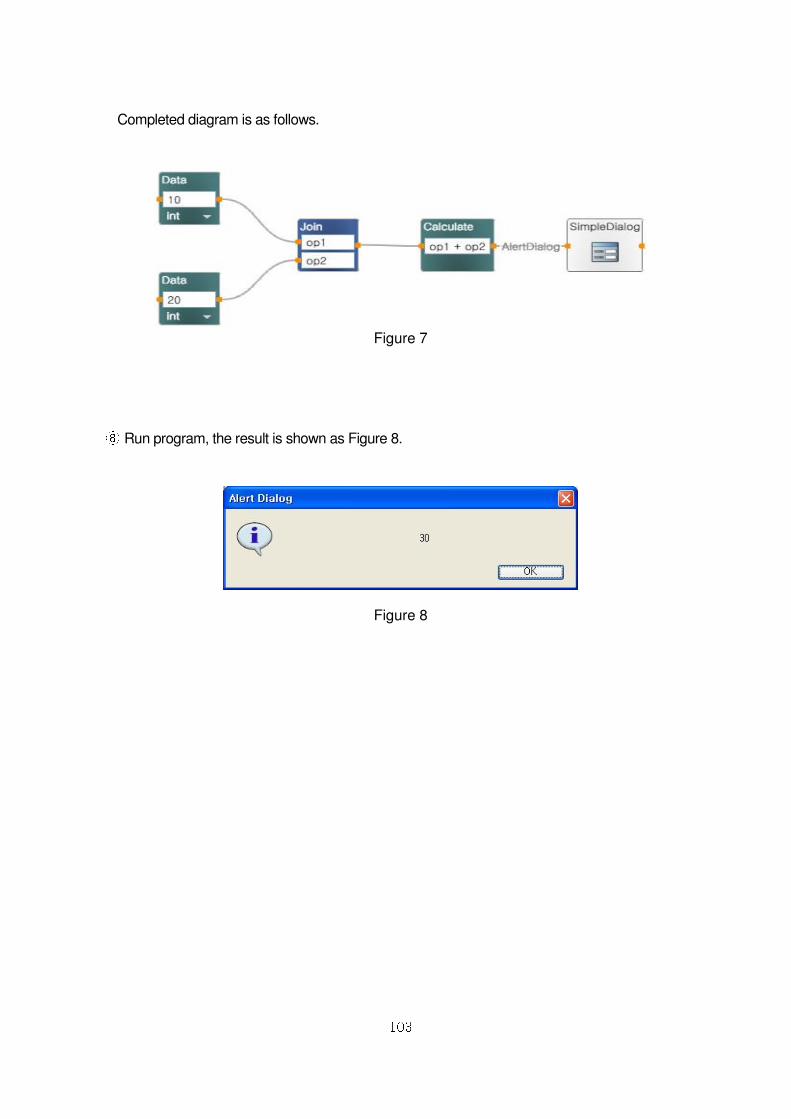
Completed diagram is as follows.
Figure 7
⑧ Run program, the result is shown as Figure 8.
Figure 8
104
77..55 IIff AAccttiivviittyy
In this chapter, it shows how to use If activity. In order to test “IF” scenario, receive the two
values, then compare the value. If two values are same, it shows “Same”, if not, it shows
“Different” message.
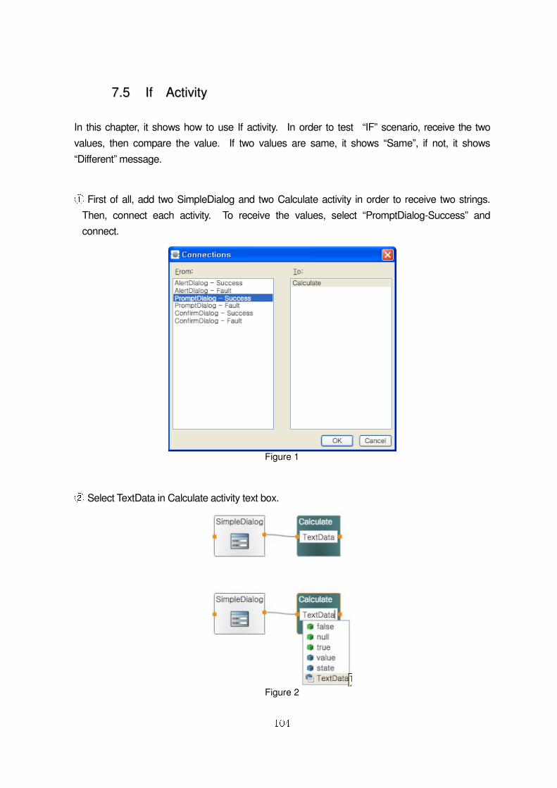
① First of all, add two SimpleDialog and two Calculate activity in order to receive two strings.
Then, connect each activity. To receive the values, select “PromptDialog-Success” and
connect.
Figure 1
② Select TextData in Calculate activity text box.
Figure 2
105
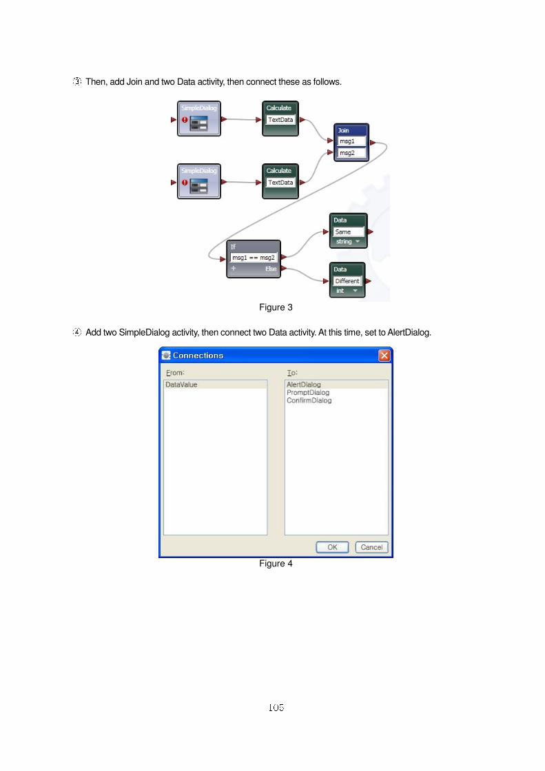
③ Then, add Join and two Data activity, then connect these as follows.
Figure 3
④ Add two SimpleDialog activity, then connect two Data activity. At this time, set to AlertDialog.
Figure 4
106
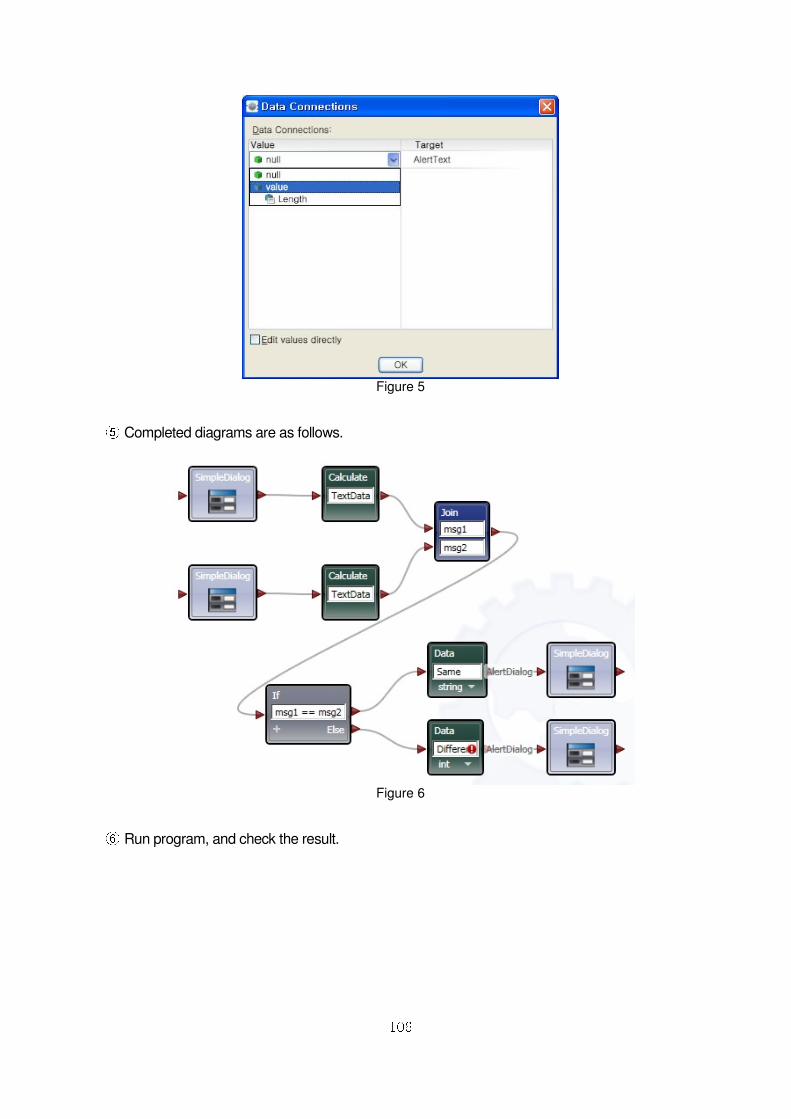
Figure 5
⑤ Completed diagrams are as follows.
Figure 6
⑥ Run program, and check the result.
107
77..66 Switch AAccttiivviittyy
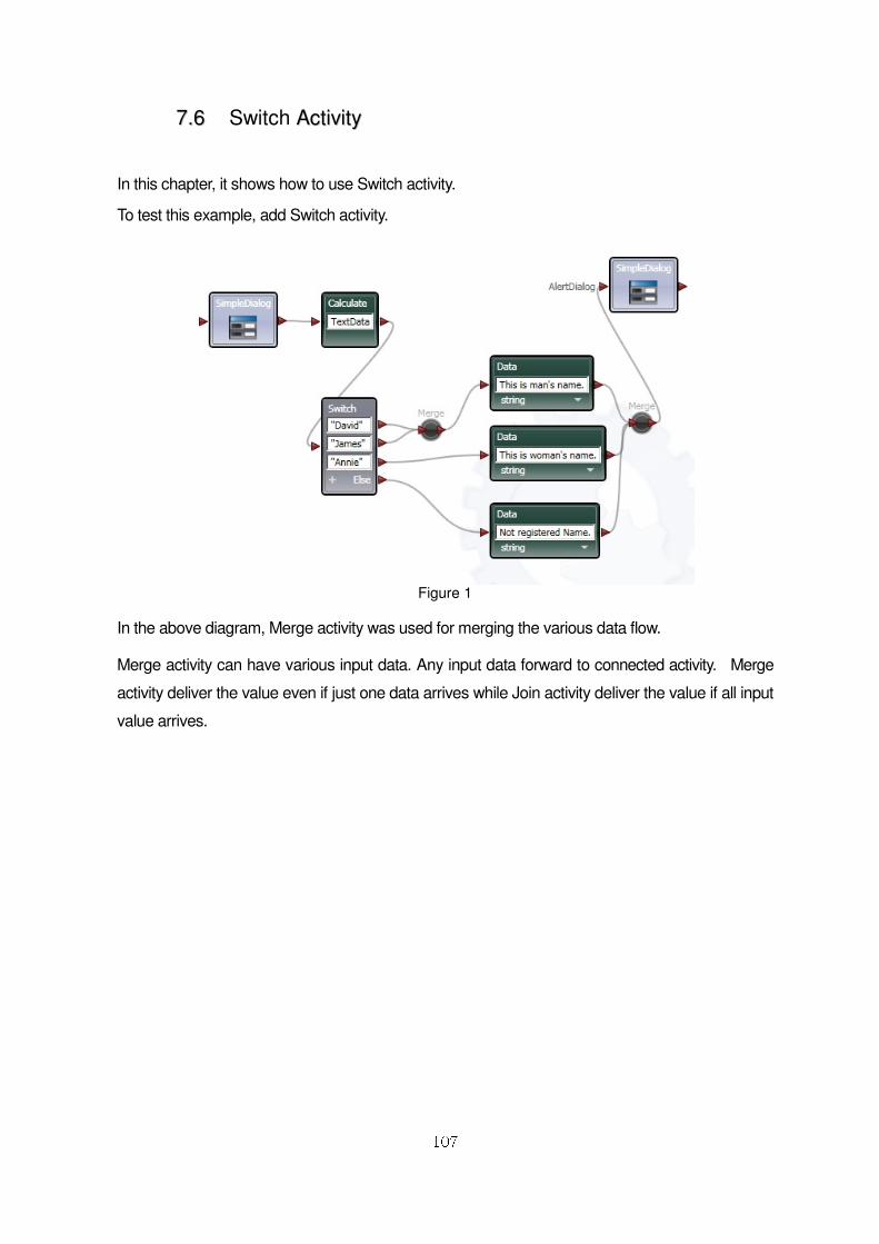
In this chapter, it shows how to use Switch activity.
To test this example, add Switch activity.
Figure 1
In the above diagram, Merge activity was used for merging the various data flow.
Merge activity can have various input data. Any input data forward to connected activity. Merge
activity deliver the value even if just one data arrives while Join activity deliver the value if all input
value arrives.
108
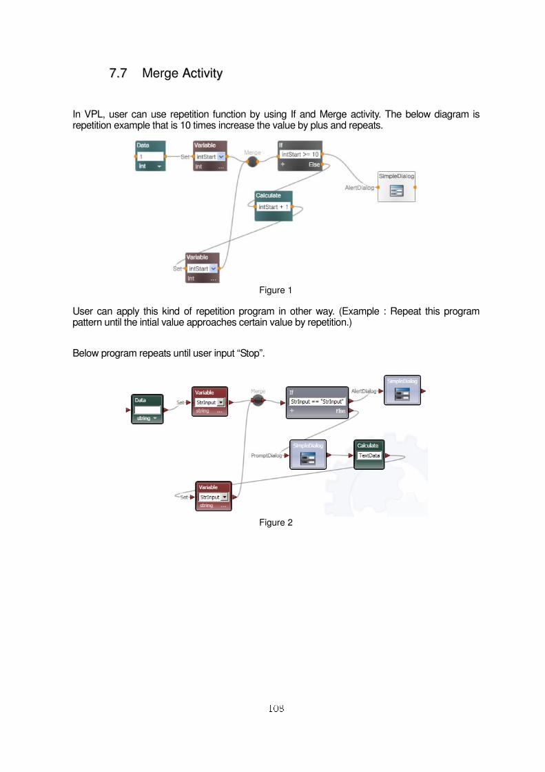
77..77 Merge AAccttiivviittyy
In VPL, user can use repetition function by using If and Merge activity. The below diagram is repetition example that is 10 times increase the value by plus and repeats.
Figure 1
User can apply this kind of repetition program in other way. (Example : Repeat this program pattern until the intial value approaches certain value by repetition.)
Below program repeats until user input “Stop”.
Figure 2
109
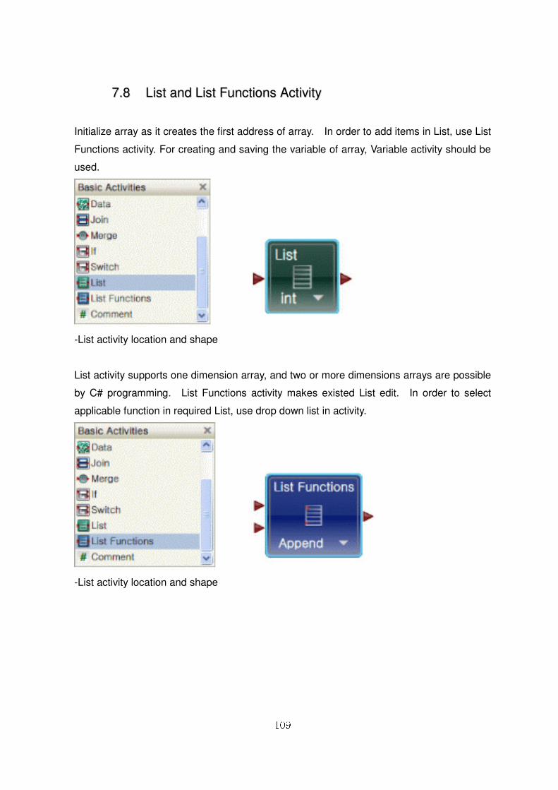
77..88 LLiisstt aanndd LLiisstt FFuunnccttiioonnss AAccttiivviittyy
Initialize array as it creates the first address of array. In order to add items in List, use List
Functions activity. For creating and saving the variable of array, Variable activity should be
used.
-List activity location and shape
List activity supports one dimension array, and two or more dimensions arrays are possible
by C# programming. List Functions activity makes existed List edit. In order to select
applicable function in required List, use drop down list in activity.
-List activity location and shape
110
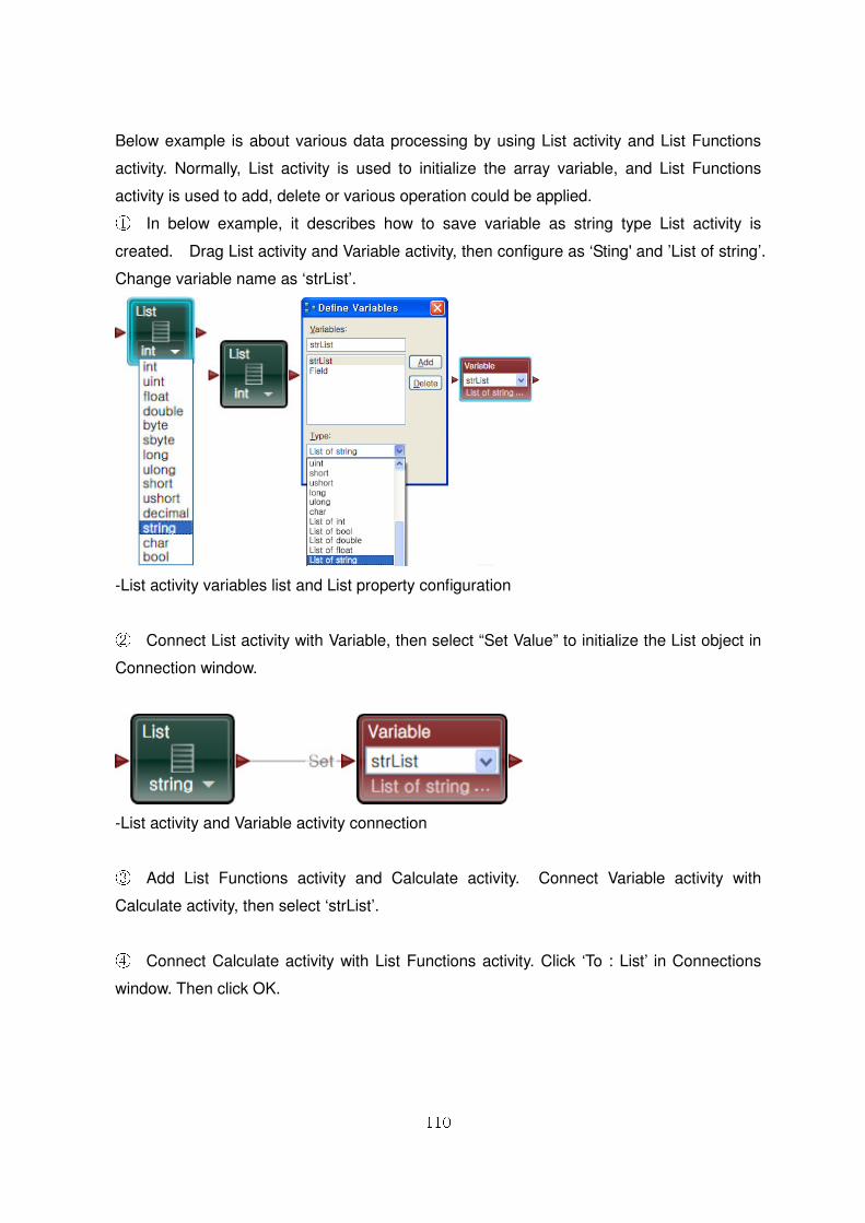
Below example is about various data processing by using List activity and List Functions
activity. Normally, List activity is used to initialize the array variable, and List Functions
activity is used to add, delete or various operation could be applied. ① In below example, it describes how to save variable as string type List activity is
created. Drag List activity and Variable activity, then configure as ‘Sting' and ’List of string’.
Change variable name as ‘strList’.
-List activity variables list and List property configuration
② Connect List activity with Variable, then select “Set Value” to initialize the List object in
Connection window.
-List activity and Variable activity connection
③ Add List Functions activity and Calculate activity. Connect Variable activity with
Calculate activity, then select ‘strList’.
④ Connect Calculate activity with List Functions activity. Click ‘To : List’ in Connections
window. Then click OK.
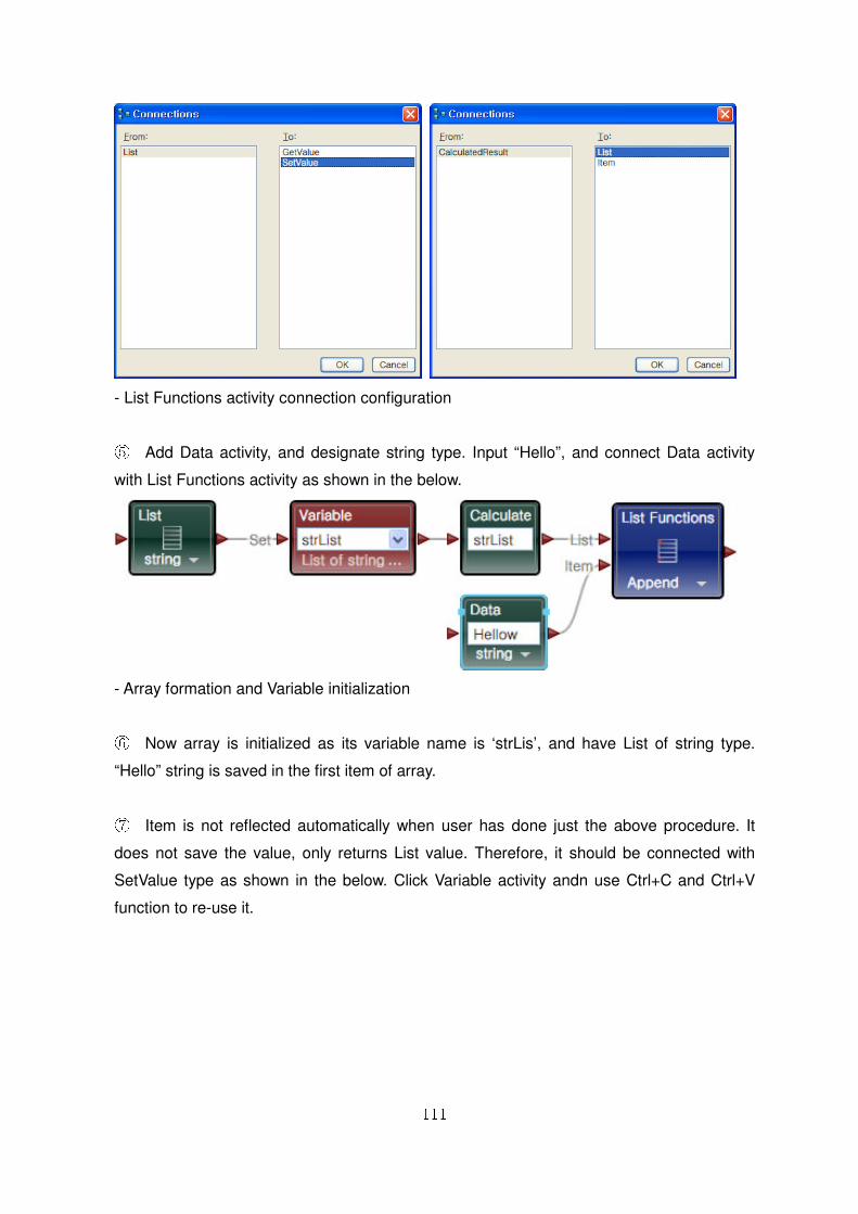
111
- List Functions activity connection configuration
⑤ Add Data activity, and designate string type. Input “Hello”, and connect Data activity
with List Functions activity as shown in the below.
- Array formation and Variable initialization
⑥ Now array is initialized as its variable name is ‘strLis’, and have List of string type.
“Hello” string is saved in the first item of array.
⑦ Item is not reflected automatically when user has done just the above procedure. It
does not save the value, only returns List value. Therefore, it should be connected with
SetValue type as shown in the below. Click Variable activity andn use Ctrl+C and Ctrl+V
function to re-use it.
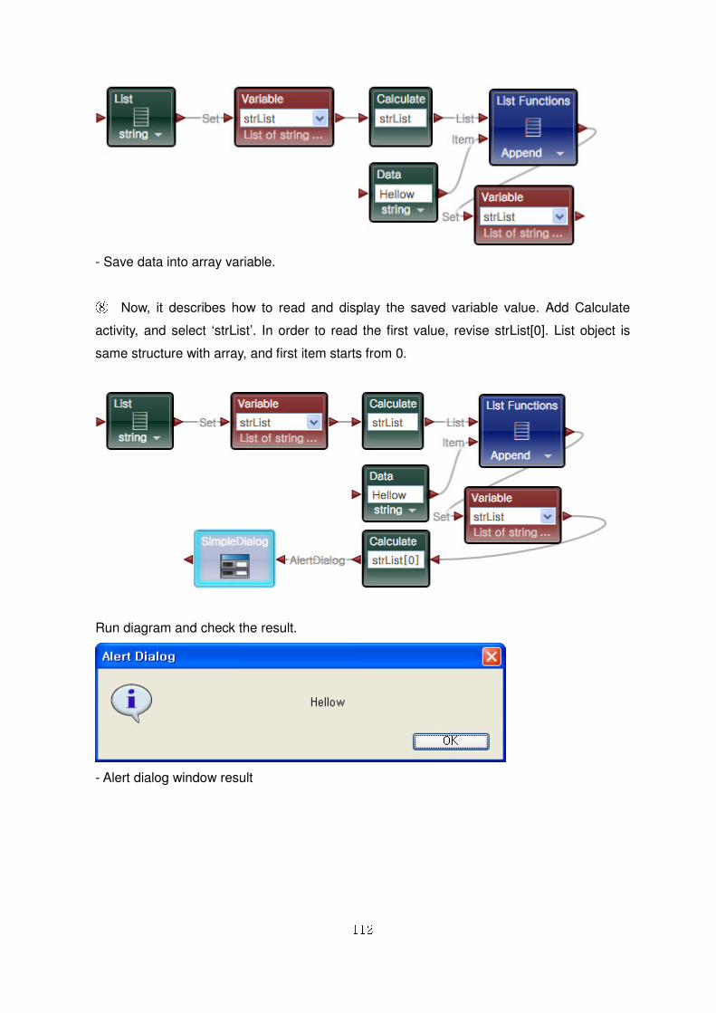
112
- Save data into array variable.
⑧ Now, it describes how to read and display the saved variable value. Add Calculate
activity, and select ‘strList’. In order to read the first value, revise strList[0]. List object is
same structure with array, and first item starts from 0.
Run diagram and check the result.
- Alert dialog window result
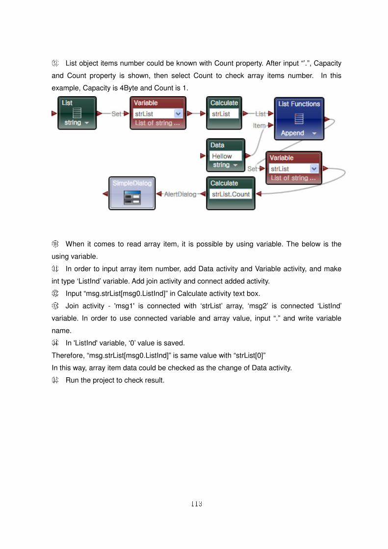
113
⑨ List object items number could be known with Count property. After input “’.”, Capacity
and Count property is shown, then select Count to check array items number. In this
example, Capacity is 4Byte and Count is 1.
⑩ When it comes to read array item, it is possible by using variable. The below is the
using variable. ⑪ In order to input array item number, add Data activity and Variable activity, and make
int type ‘ListInd’ variable. Add join activity and connect added activity. ⑫ Input “msg.strList[msg0.ListInd]” in Calculate activity text box. ⑬ Join activity - 'msg1' is connected with ‘strList’ array, ‘msg2’ is connected ‘ListInd’
variable. In order to use connected variable and array value, input “.” and write variable
name. ⑭ In 'ListInd' variable, ‘0’ value is saved.
Therefore, “msg.strList[msg0.ListInd]” is same value with “strList[0]”
In this way, array item data could be checked as the change of Data activity. ⑮ Run the project to check result.
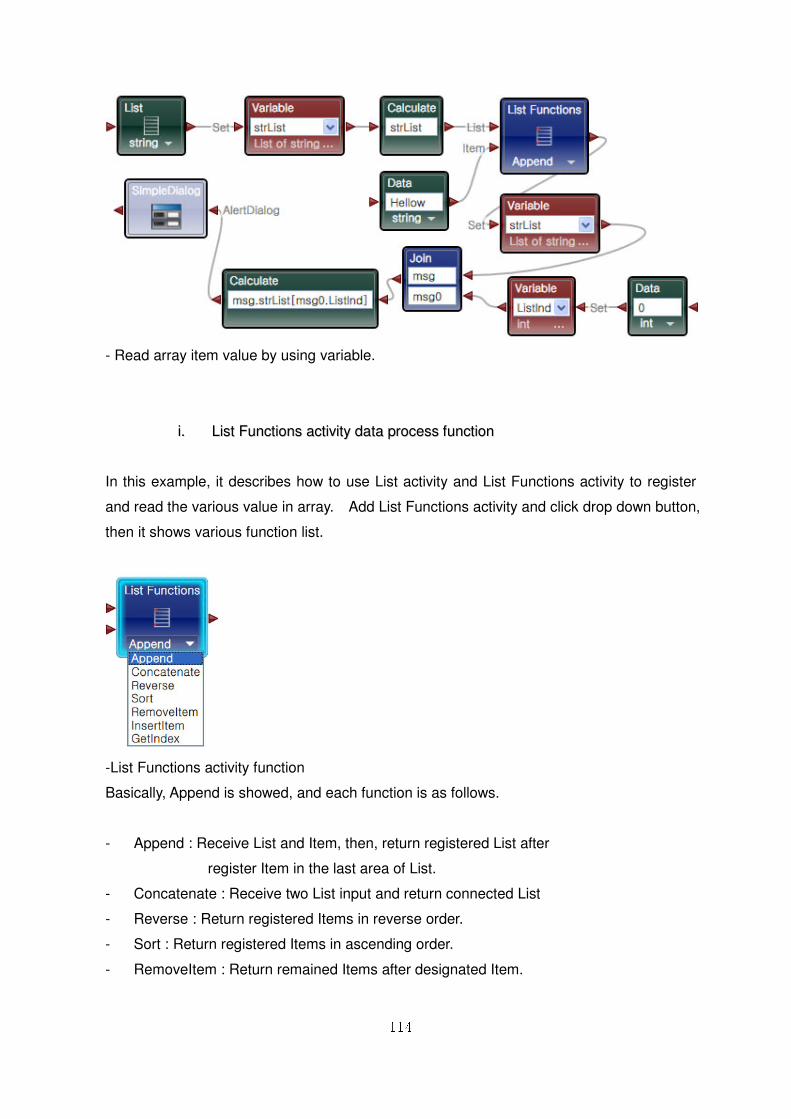
114
- Read array item value by using variable.
ii.. LLiisstt FFuunnccttiioonnss aaccttiivviittyy ddaattaa pprroocceessss ffuunnccttiioonn
In this example, it describes how to use List activity and List Functions activity to register
and read the various value in array. Add List Functions activity and click drop down button,
then it shows various function list.
-List Functions activity function
Basically, Append is showed, and each function is as follows.
- Append : Receive List and Item, then, return registered List after
register Item in the last area of List.
- Concatenate : Receive two List input and return connected List
- Reverse : Return registered Items in reverse order.
- Sort : Return registered Items in ascending order.
- RemoveItem : Return remained Items after designated Item.
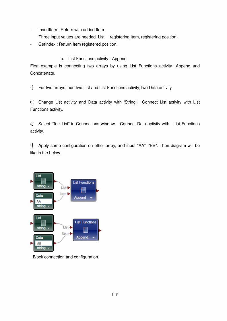
115
- InsertItem : Return with added Item.
Three input values are needed. List, registering Item, registering position.
- GetIndex : Return Item registered position.
a. List Functions activity - AAppppeenndd
First example is connecting two arrays by using List Functions activity- Append and
Concatenate.
① For two arrays, add two List and List Functions activity, two Data activity.
② Change List activity and Data activity with ‘String’. Connect List activity with List
Functions activity.
③ Select “To : List” in Connections window. Connect Data activity with List Functions
activity.
④ Apply same configuration on other array, and input “AA”, “BB”. Then diagram will be
like in the below.
- Block connection and configuration.
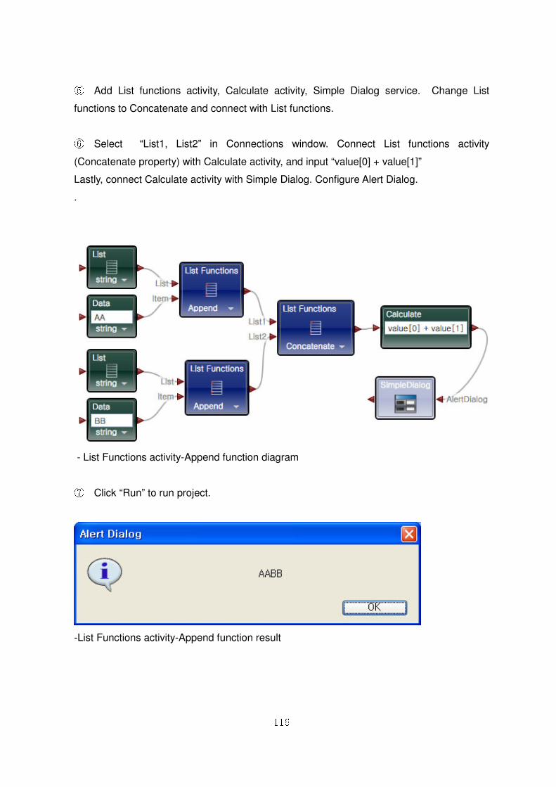
116
⑤ Add List functions activity, Calculate activity, Simple Dialog service. Change List
functions to Concatenate and connect with List functions.
⑥ Select “List1, List2” in Connections window. Connect List functions activity
(Concatenate property) with Calculate activity, and input “value[0] + value[1]”
Lastly, connect Calculate activity with Simple Dialog. Configure Alert Dialog.
.
- List Functions activity-Append function diagram
⑦ Click “Run” to run project.
-List Functions activity-Append function result
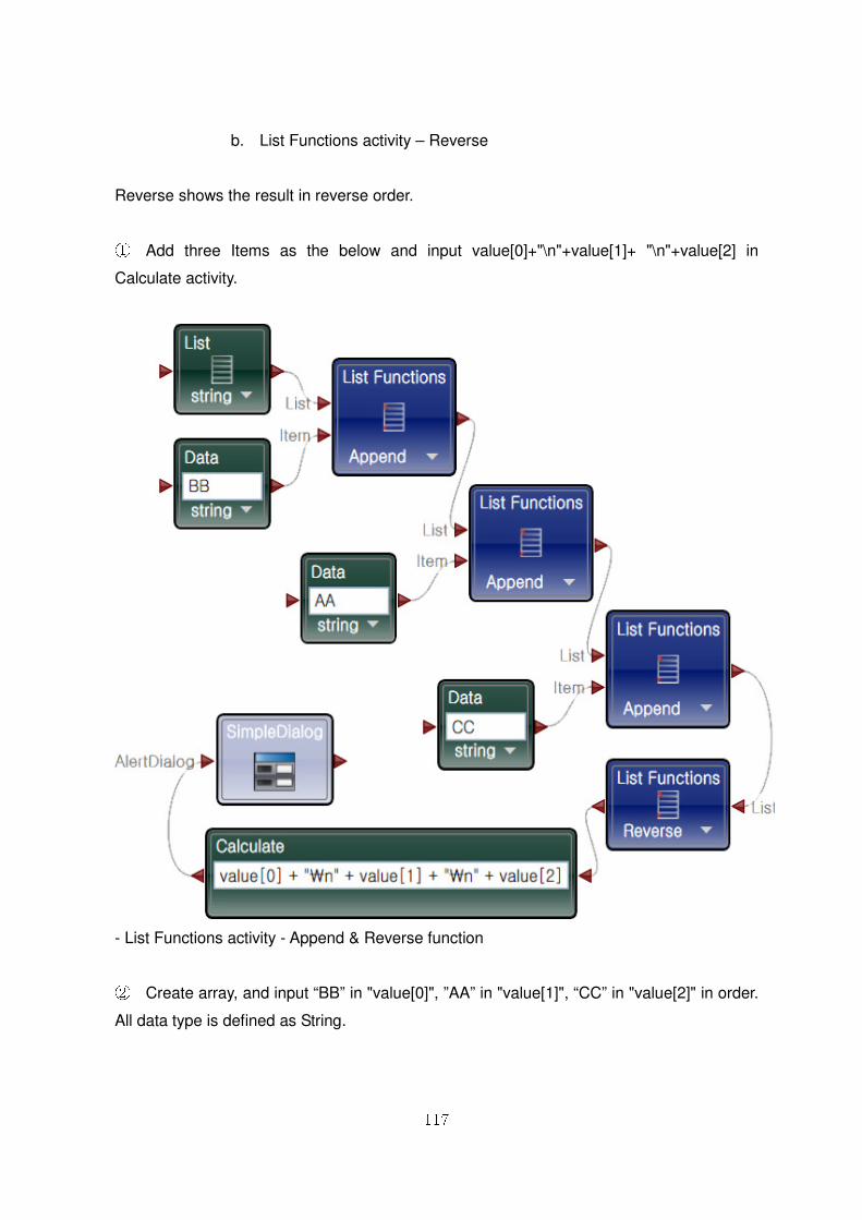
117
b. List Functions activity – Reverse
Reverse shows the result in reverse order.
① Add three Items as the below and input value[0]+"\n"+value[1]+ "\n"+value[2] in
Calculate activity.
- List Functions activity - Append & Reverse function
② Create array, and input “BB” in "value[0]", ”AA” in "value[1]", “CC” in "value[2]" in order.
All data type is defined as String.
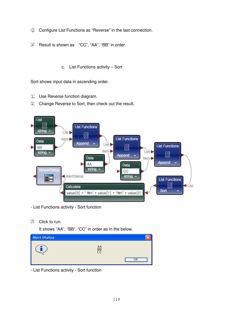
118
③ Configure List Functions as “Reverse” in the last connection.
④ Result is shown as “CC”, “AA”, “BB” in order.
c. List Functions activity – Sort
Sort shows input data in ascending order.
① Use Reverse function diagram. ② Change Reverse to Sort, then check out the result.
- List Functions activity - Sort function
③ Click to run.
It shows “AA”, “BB”, “CC” in order as in the below.
- List Functions activity - Sort function
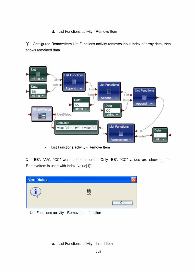
119
d. List Functions activity - Remove Item
① Configured RemoveItem List Functions activity removes input Index of array data, then
shows remained data.
- List Functions activity - Remove Item
② “BB”, ”AA”, “CC” were added in order. Only “BB”, “CC” values are showed after
RemoveItem is used with index “value[1]".
- List Functions activity - RemoveItem function
e. List Functions activity - Insert Item
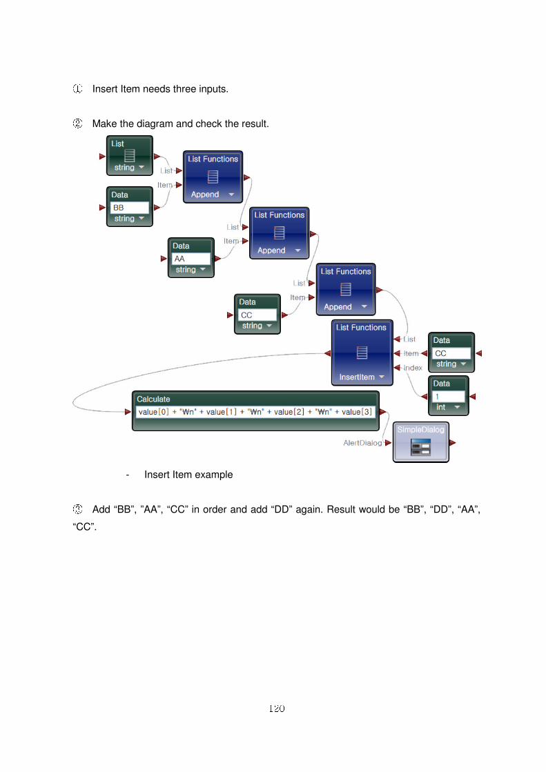
120
① Insert Item needs three inputs.
② Make the diagram and check the result.
- Insert Item example
③ Add “BB”, ”AA”, “CC” in order and add “DD” again. Result would be “BB”, “DD”, “AA”,
“CC”.
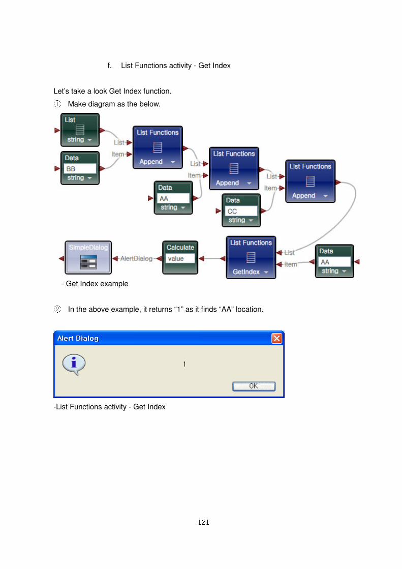
121
f. List Functions activity - Get Index
Let’s take a look Get Index function. ① Make diagram as the below.
- Get Index example
② In the above example, it returns “1” as it finds “AA” location.
-List Functions activity - Get Index
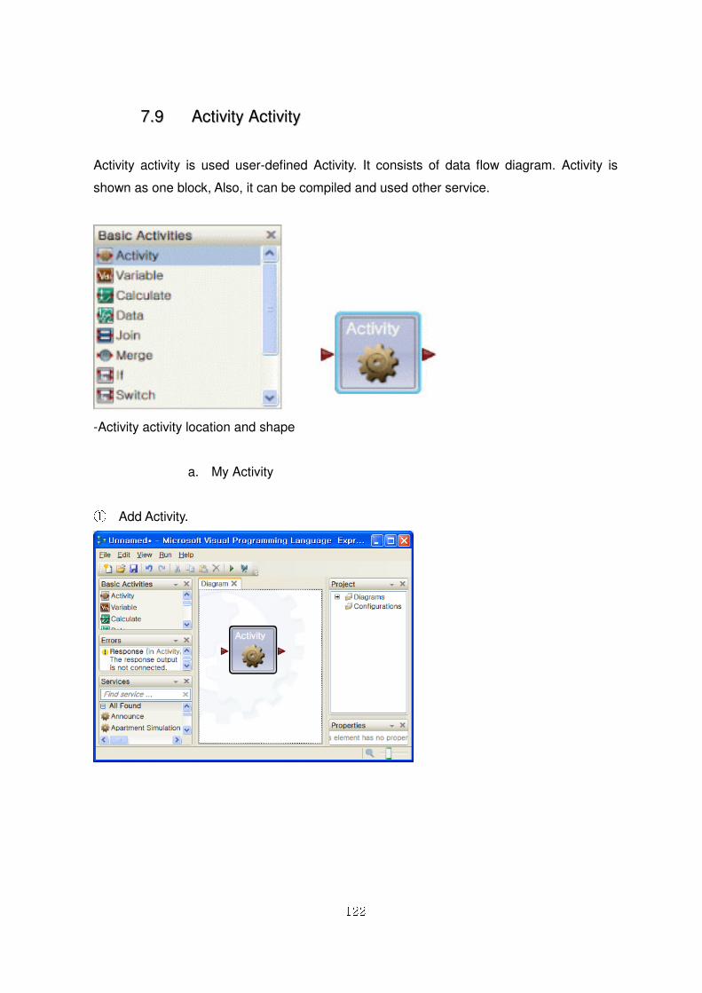
122
77..99 AAccttiivviittyy AAccttiivviittyy
Activity activity is used user-defined Activity. It consists of data flow diagram. Activity is
shown as one block, Also, it can be compiled and used other service.
-Activity activity location and shape
a. My Activity
① Add Activity.
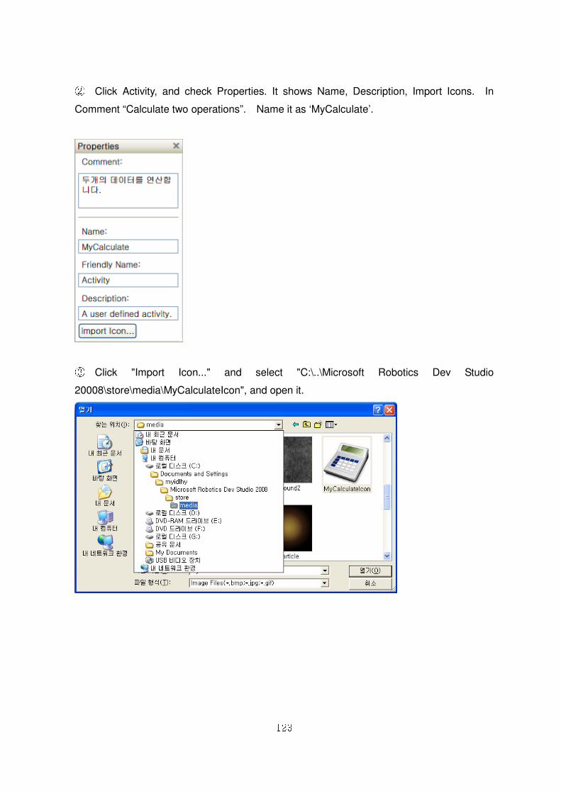
123
② Click Activity, and check Properties. It shows Name, Description, Import Icons. In
Comment “Calculate two operations”. Name it as ‘MyCalculate’.
③ Click "Import Icon..." and select "C:\..\Microsoft Robotics Dev Studio
20008\store\media\MyCalculateIcon", and open it.
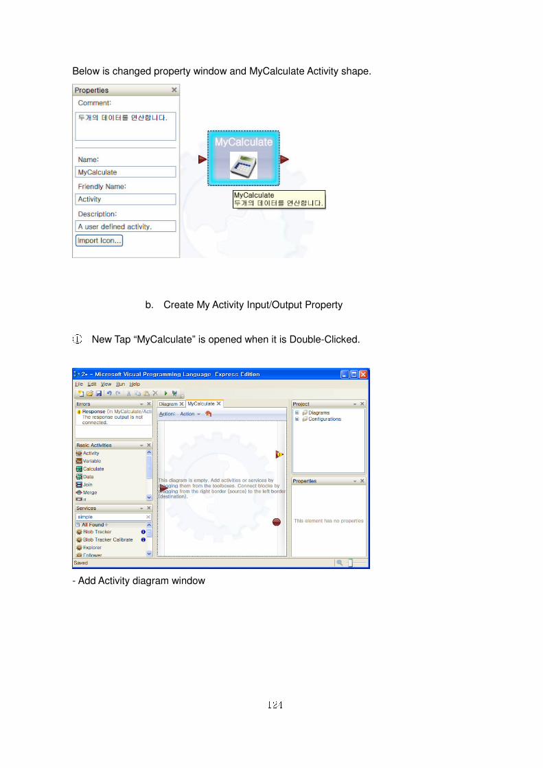
124
Below is changed property window and MyCalculate Activity shape.
b. Create My Activity Input/Output Property
① New Tap “MyCalculate” is opened when it is Double-Clicked.
- Add Activity diagram window
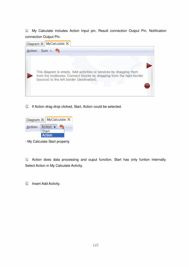
125
② My Calculate includes Action Input pin, Result connection Output Pin, Notification
connection Output Pin.
③ If Action drag drop clicked, Start, Action could be selected.
- My Calculate Start property
④ Action does data processing and ouput function, Start has only funtion internally.
Select Action in My Calculate Activity.
⑤ Insert Add Activity.
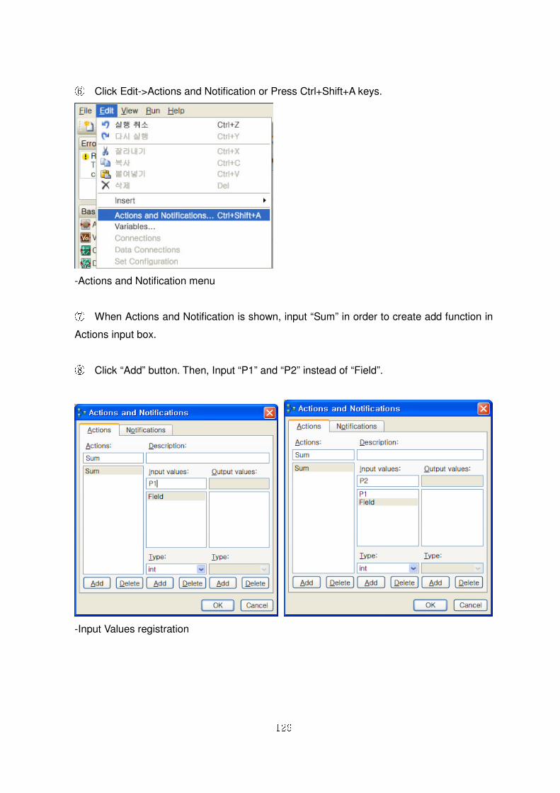
126
⑥ Click Edit->Actions and Notification or Press Ctrl+Shift+A keys.
-Actions and Notification menu
⑦ When Actions and Notification is shown, input “Sum” in order to create add function in
Actions input box.
⑧ Click “Add” button. Then, Input “P1” and “P2” instead of “Field”.
-Input Values registration
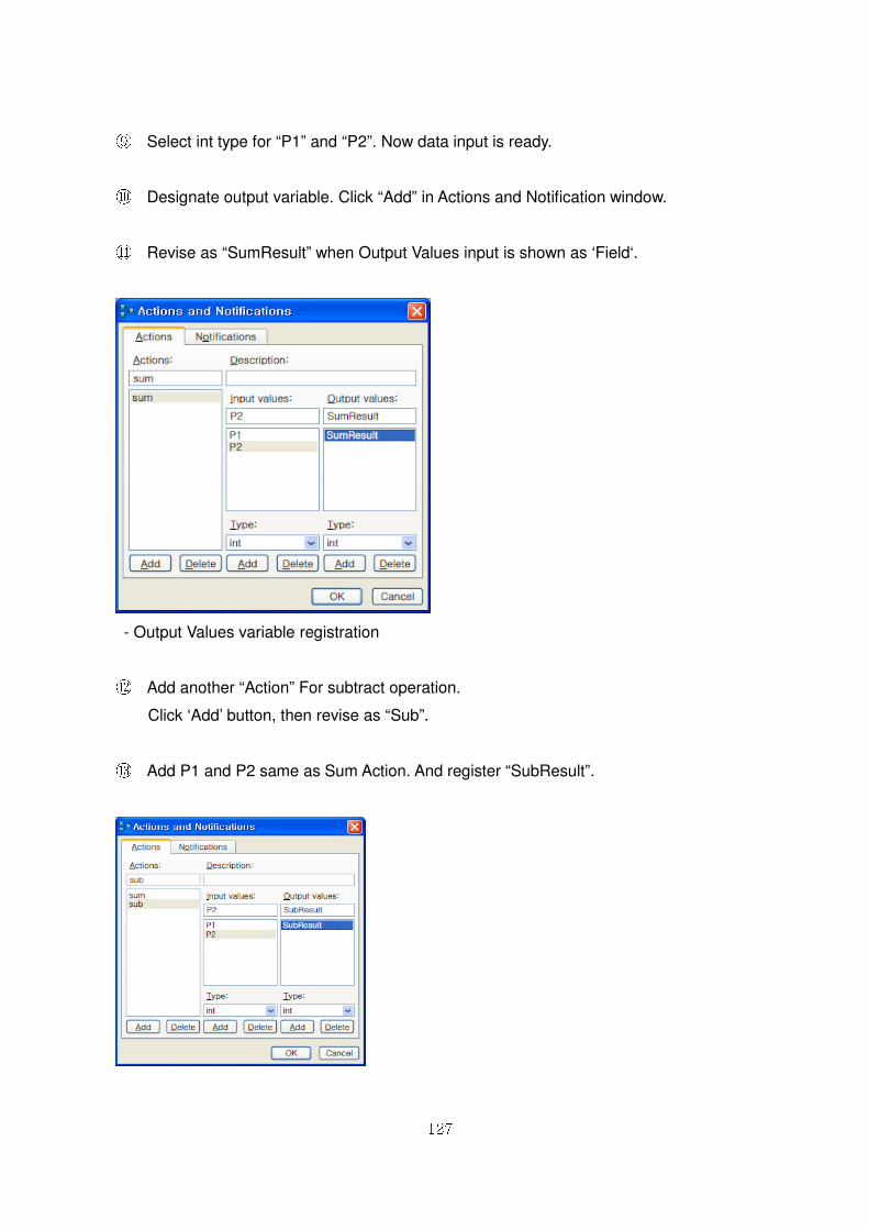
127
⑨ Select int type for “P1” and “P2”. Now data input is ready.
⑩ Designate output variable. Click “Add” in Actions and Notification window.
⑪ Revise as “SumResult” when Output Values input is shown as ‘Field‘.
- Output Values variable registration
⑫ Add another “Action” For subtract operation.
Click ‘Add’ button, then revise as “Sub”.
⑬ Add P1 and P2 same as Sum Action. And register “SubResult”.
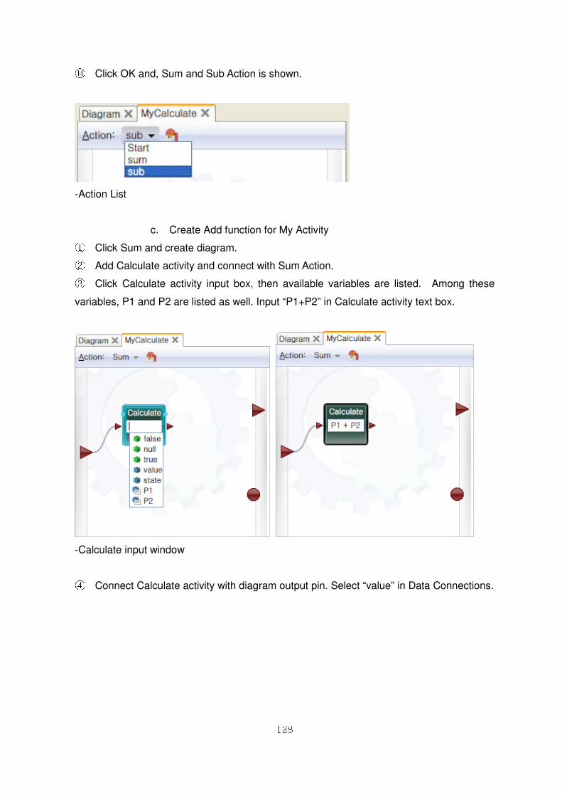
128
⑭ Click OK and, Sum and Sub Action is shown.
-Action List
c. Create Add function for My Activity ① Click Sum and create diagram. ② Add Calculate activity and connect with Sum Action. ③ Click Calculate activity input box, then available variables are listed. Among these
variables, P1 and P2 are listed as well. Input “P1+P2” in Calculate activity text box.
-Calculate input window
④ Connect Calculate activity with diagram output pin. Select “value” in Data Connections.
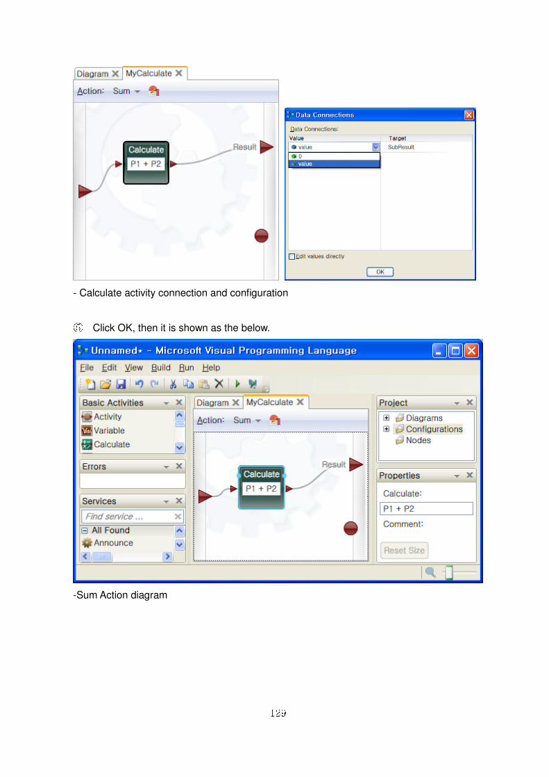
129
- Calculate activity connection and configuration
⑤ Click OK, then it is shown as the below.
-Sum Action diagram
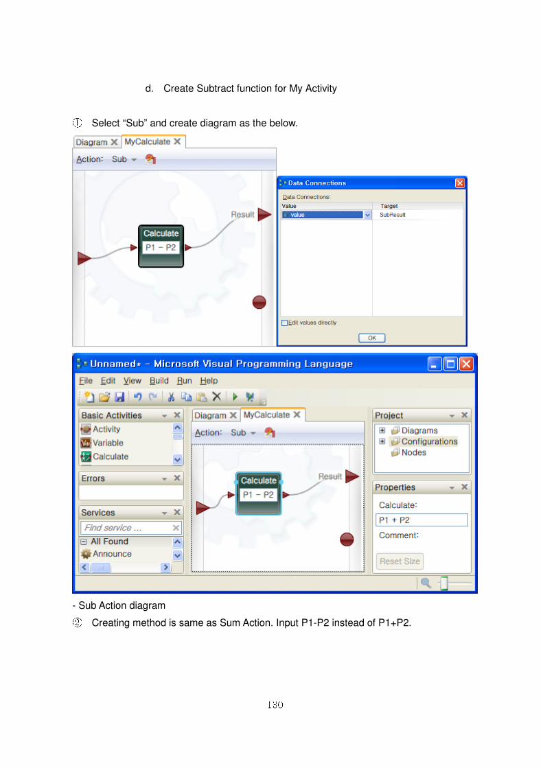
130
d. Create Subtract function for My Activity
① Select “Sub” and create diagram as the below.
- Sub Action diagram ② Creating method is same as Sum Action. Input P1-P2 instead of P1+P2.
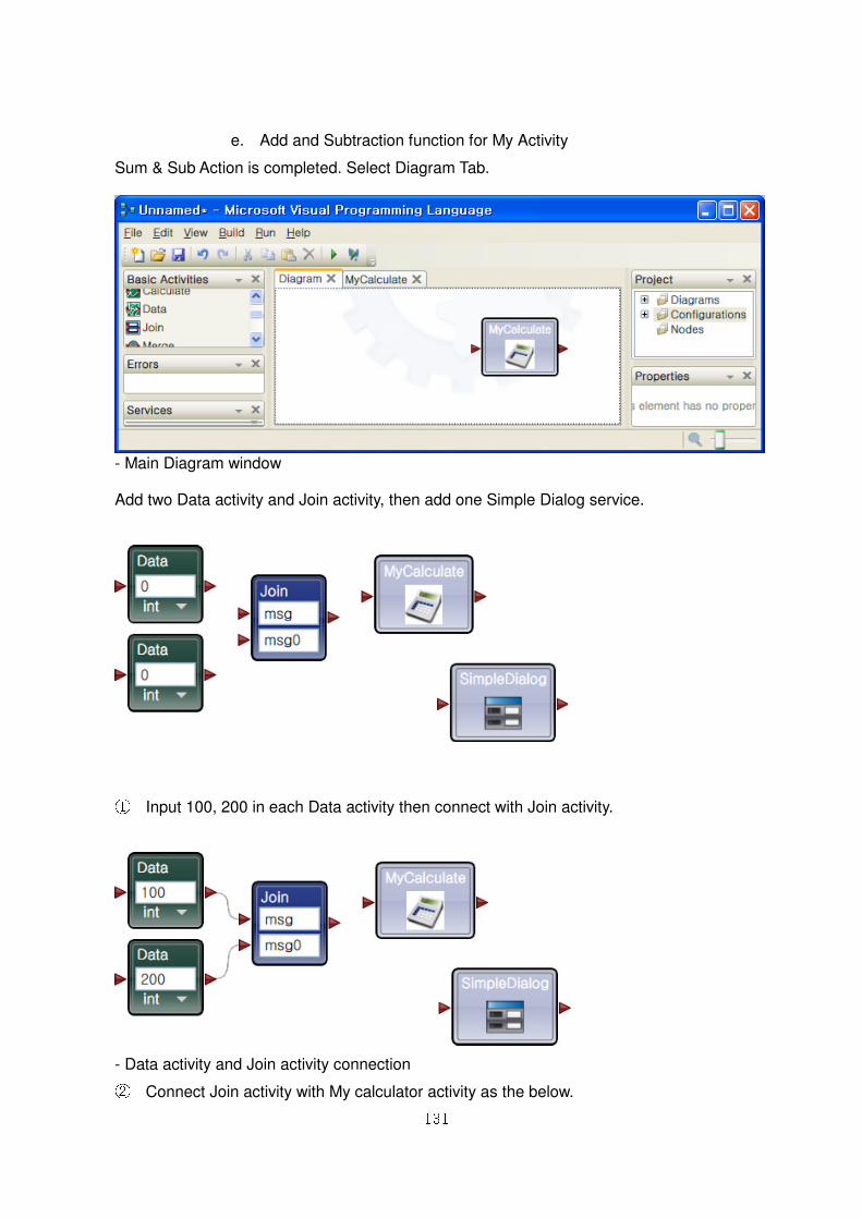
131
e. Add and Subtraction function for My Activity
Sum & Sub Action is completed. Select Diagram Tab.
- Main Diagram window Add two Data activity and Join activity, then add one Simple Dialog service.
① Input 100, 200 in each Data activity then connect with Join activity.
- Data activity and Join activity connection ② Connect Join activity with My calculator activity as the below.
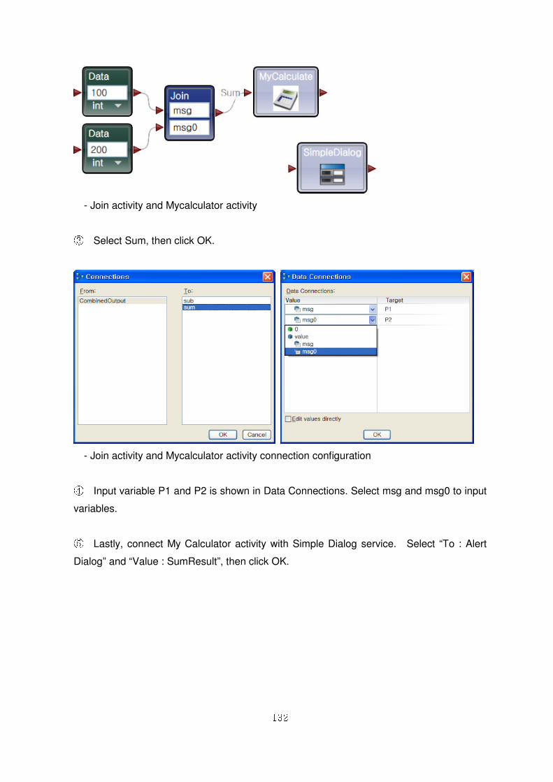
132
- Join activity and Mycalculator activity
③ Select Sum, then click OK.
- Join activity and Mycalculator activity connection configuration
④ Input variable P1 and P2 is shown in Data Connections. Select msg and msg0 to input
variables.
⑤ Lastly, connect My Calculator activity with Simple Dialog service. Select “To : Alert
Dialog” and “Value : SumResult”, then click OK.
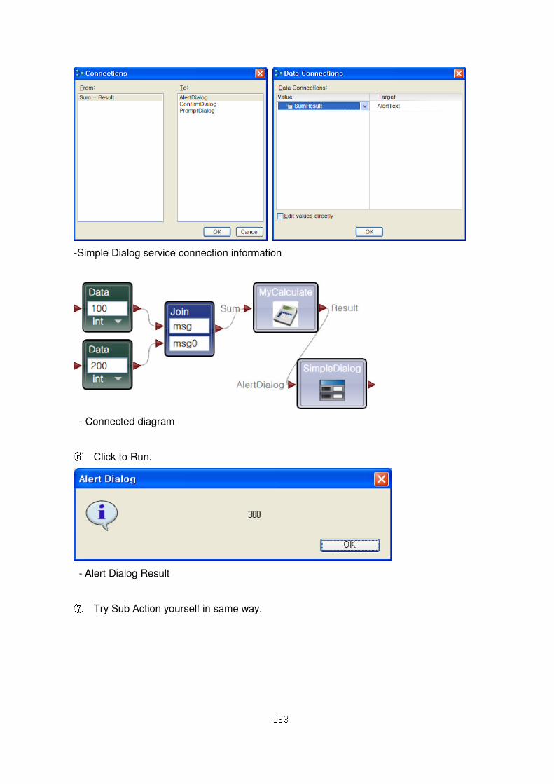
133
-Simple Dialog service connection information
- Connected diagram
⑥ Click to Run.
- Alert Dialog Result
⑦ Try Sub Action yourself in same way.
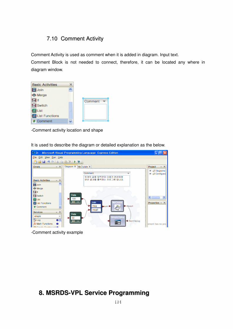
134
77..1100 CCoommmmeenntt AAccttiivviittyy
Comment Activity is used as comment when it is added in diagram. Input text.
Comment Block is not needed to connect, therefore, it can be located any where in
diagram window.
-Comment activity location and shape
It is used to describe the diagram or detailed explanation as the below.
-Comment activity example
88.. MMSSRRDDSS--VVPPLL SSeerrvviiccee PPrrooggrraammmmiinngg
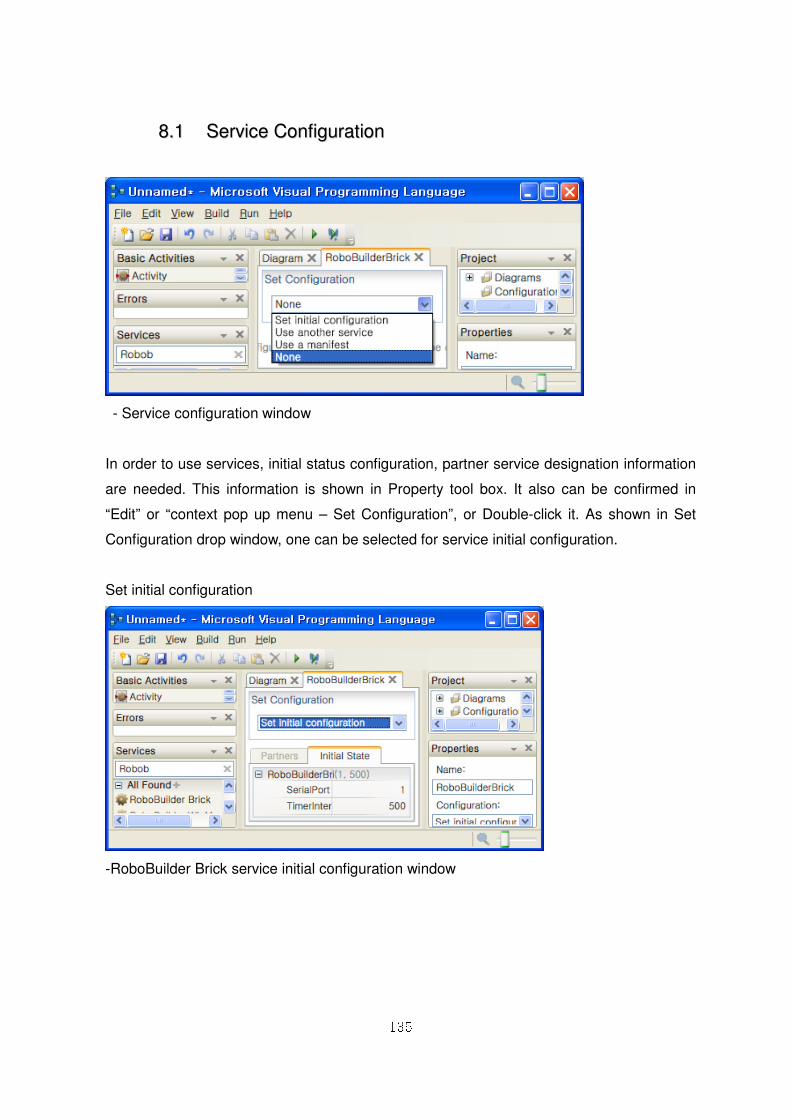
135
88..11 SSeerrvviiccee CCoonnffiigguurraattiioonn
- Service configuration window
In order to use services, initial status configuration, partner service designation information
are needed. This information is shown in Property tool box. It also can be confirmed in
“Edit” or “context pop up menu – Set Configuration”, or Double-click it. As shown in Set
Configuration drop window, one can be selected for service initial configuration.
Set initial configuration
-RoboBuilder Brick service initial configuration window
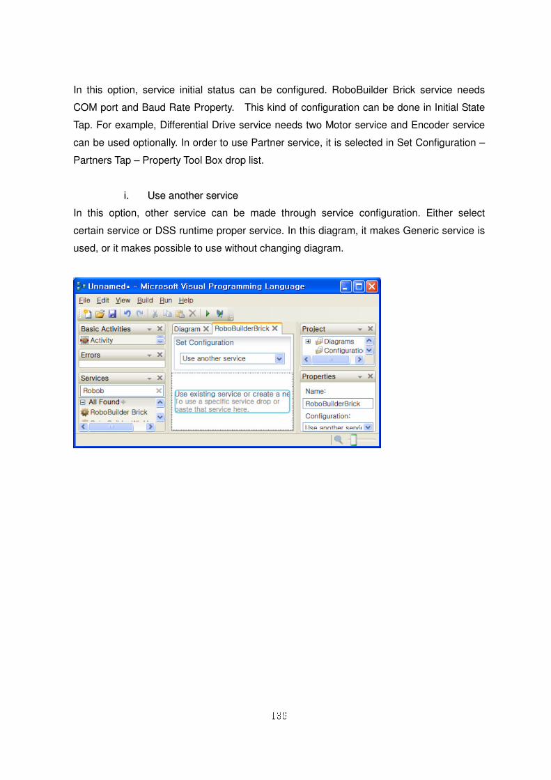
136
In this option, service initial status can be configured. RoboBuilder Brick service needs
COM port and Baud Rate Property. This kind of configuration can be done in Initial State
Tap. For example, Differential Drive service needs two Motor service and Encoder service
can be used optionally. In order to use Partner service, it is selected in Set Configuration –
Partners Tap – Property Tool Box drop list.
ii.. UUssee aannootthheerr sseerrvviiccee
In this option, other service can be made through service configuration. Either select
certain service or DSS runtime proper service. In this diagram, it makes Generic service is
used, or it makes possible to use without changing diagram.
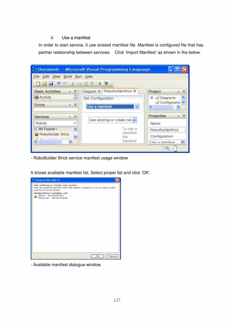
137
iiii.. UUssee aa mmaanniiffeesstt
In order to start service, it use existed manifest file. Manifest is configured file that has
partner relationship between services. Click ‘Import Manifest’ as shown in the below.
- RoboBuilder Brick service manifest usage window
It shows available manifest list. Select proper list and click ‘OK’.
- Available manifest dialogue window.
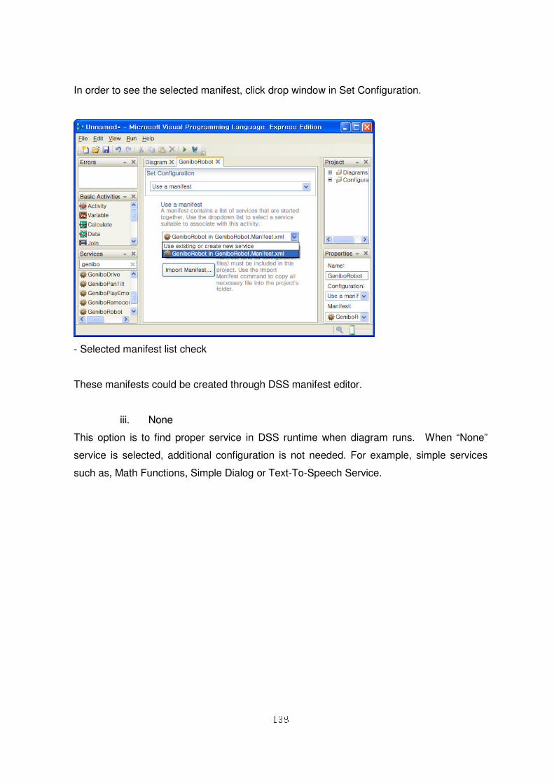
138
In order to see the selected manifest, click drop window in Set Configuration.
- Selected manifest list check
These manifests could be created through DSS manifest editor.
iiiiii.. NNoonnee
This option is to find proper service in DSS runtime when diagram runs. When “None”
service is selected, additional configuration is not needed. For example, simple services
such as, Math Functions, Simple Dialog or Text-To-Speech Service.
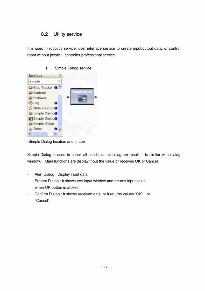
139
88..22 UUttiilliittyy sseerrvviiccee
It is used in robotics service, user interface service to create input/output data, or control
robot without joystick, controller professional service.
ii.. SSiimmppllee DDiiaalloogg sseerrvviiccee
-Simple Dialog location and shape
Simple Dialog is used to check all used example diagram result. It is similar with dialog
window. Main functions are display/input the value or receives OK or Cancel.
- Alert Dialog : Display input data.
- Prompt Dialog : It shows text input window and returns input value
when OK button is clicked.
- Confirm Dialog : It shows received data, or it returns values “OK” or
“Cancel”.
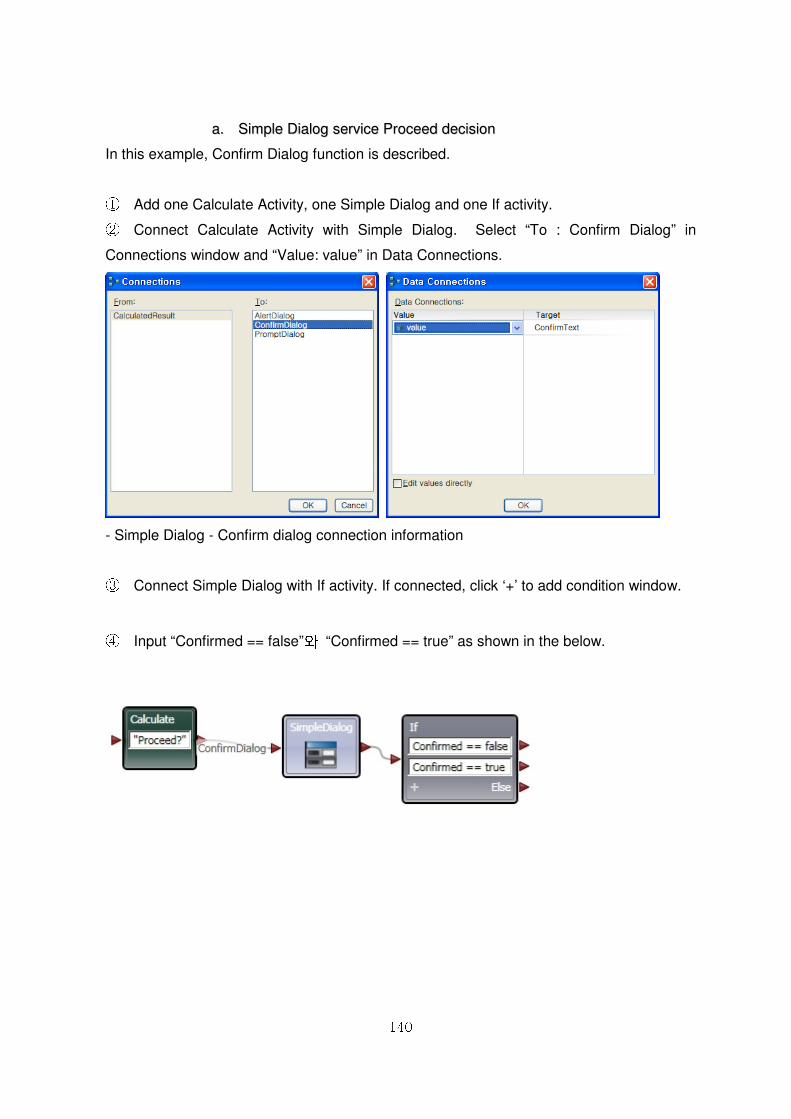
140
aa.. SSiimmppllee DDiiaalloogg sseerrvviiccee PPrroocceeeedd ddeecciissiioonn
In this example, Confirm Dialog function is described.
① Add one Calculate Activity, one Simple Dialog and one If activity. ② Connect Calculate Activity with Simple Dialog. Select “To : Confirm Dialog” in
Connections window and “Value: value” in Data Connections.
- Simple Dialog - Confirm dialog connection information
③ Connect Simple Dialog with If activity. If connected, click ‘+’ to add condition window.
④ Input “Confirmed == false”와 “Confirmed == true” as shown in the below.
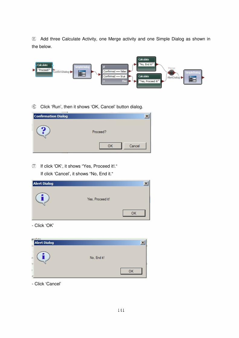
141
⑤ Add three Calculate Activity, one Merge activity and one Simple Dialog as shown in
the below.
⑥ Click ‘Run’, then it shows ‘OK, Cancel’ button dialog.
⑦ If click 'OK‘, it shows “Yes, Proceed it!.“
If click ‘Cancel’, it shows “No, End it.“
- Click ‘OK’
- Click ‘Cancel’
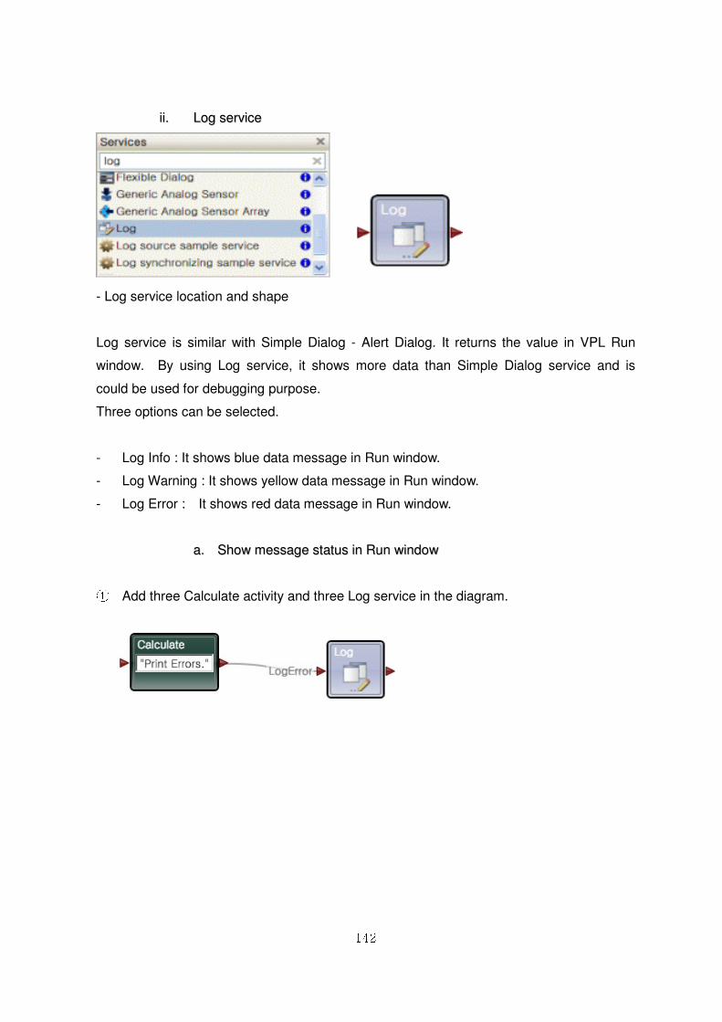
142
iiii.. LLoogg sseerrvviiccee
- Log service location and shape
Log service is similar with Simple Dialog - Alert Dialog. It returns the value in VPL Run
window. By using Log service, it shows more data than Simple Dialog service and is
could be used for debugging purpose.
Three options can be selected.
- Log Info : It shows blue data message in Run window.
- Log Warning : It shows yellow data message in Run window.
- Log Error : It shows red data message in Run window.
aa.. SShhooww mmeessssaaggee ssttaattuuss iinn RRuunn wwiinnddooww
① Add three Calculate activity and three Log service in the diagram.
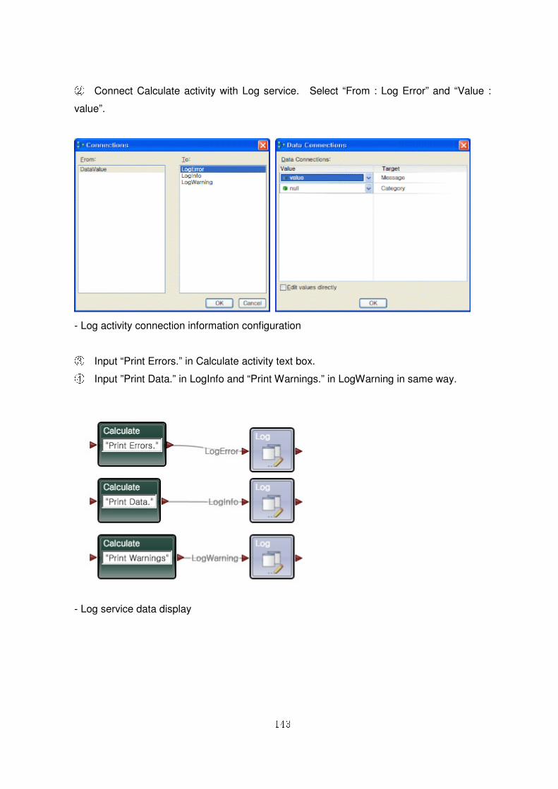
143
② Connect Calculate activity with Log service. Select “From : Log Error” and “Value :
value”.
- Log activity connection information configuration
③ Input “Print Errors.” in Calculate activity text box. ④ Input ”Print Data.” in LogInfo and “Print Warnings.” in LogWarning in same way.
- Log service data display
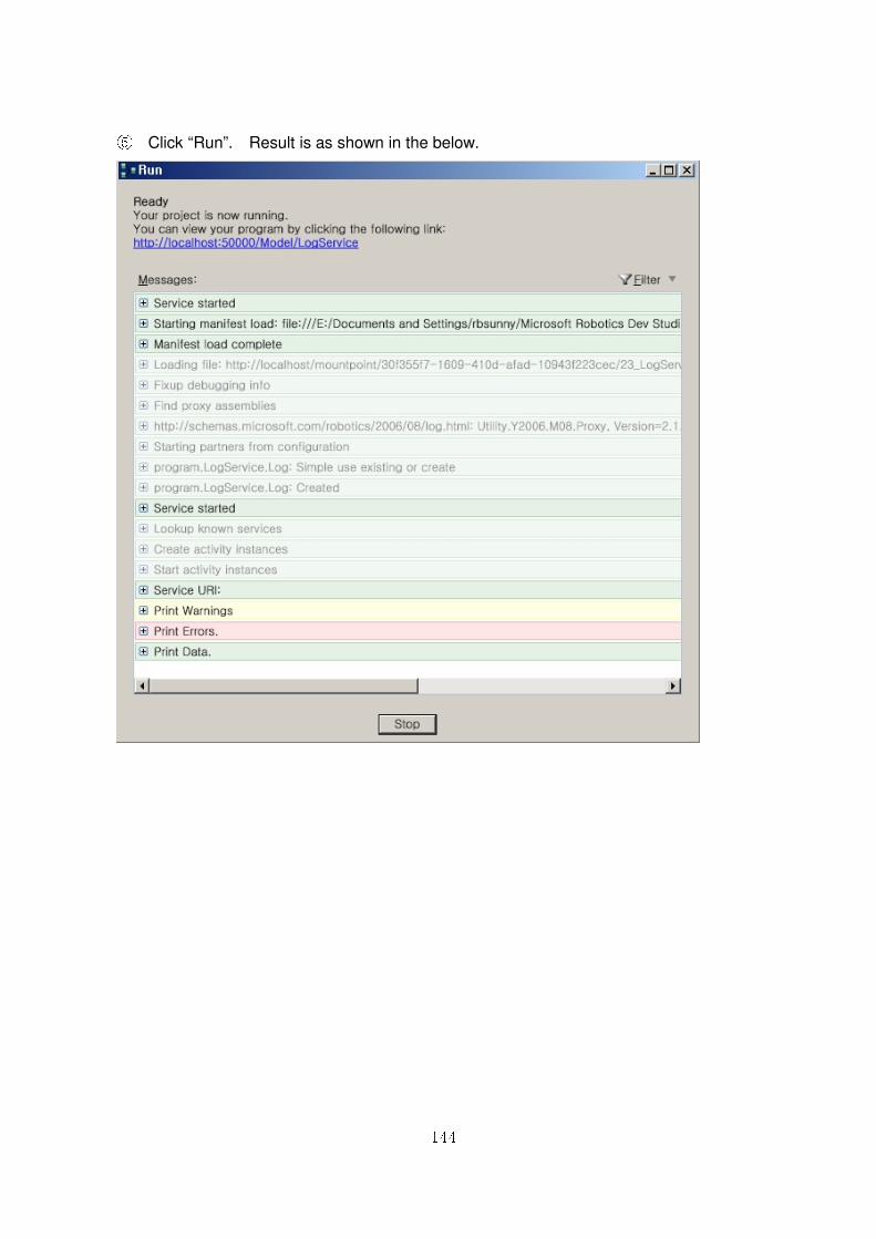
144
⑤ Click “Run”. Result is as shown in the below.
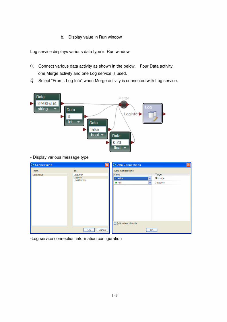
145
bb.. DDiissppllaayy vvaalluuee iinn RRuunn wwiinnddooww
Log service displays various data type in Run window.
① Connect various data activity as shown in the below. Four Data activity,
one Merge activity and one Log service is used. ② Select “From : Log Info” when Merge activity is connected with Log service.
- Display various message type
-Log service connection information configuration
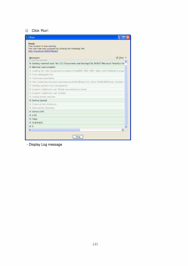
146
③ Click ‘Run’.
- Display Log message
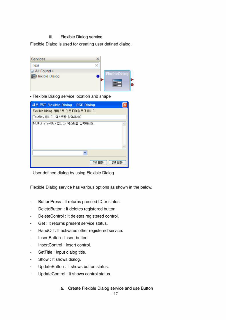
147
iiiiii.. FFlleexxiibbllee DDiiaalloogg sseerrvviiccee
Flexible Dialog is used for creating user defined dialog.
- Flexible Dialog service location and shape
- User defined dialog by using Flexible Dialog
Flexible Dialog service has various options as shown in the below.
- ButtonPress : It returns pressed ID or status.
- DeleteButton : It deletes registered button.
- DeleteControl : It deletes registered control.
- Get : It returns present service status.
- HandOff : It activates other registered service.
- InsertButton : Insert button.
- InsertControl : Insert control.
- SetTitle : Input dialog title.
- Show : It shows dialog.
- UpdateButton : It shows button status.
- UpdateControl : It shows control status.
aa.. CCrreeaattee FFlleexxiibbllee DDiiaalloogg sseerrvviiccee aanndd uussee BBuuttttoonn
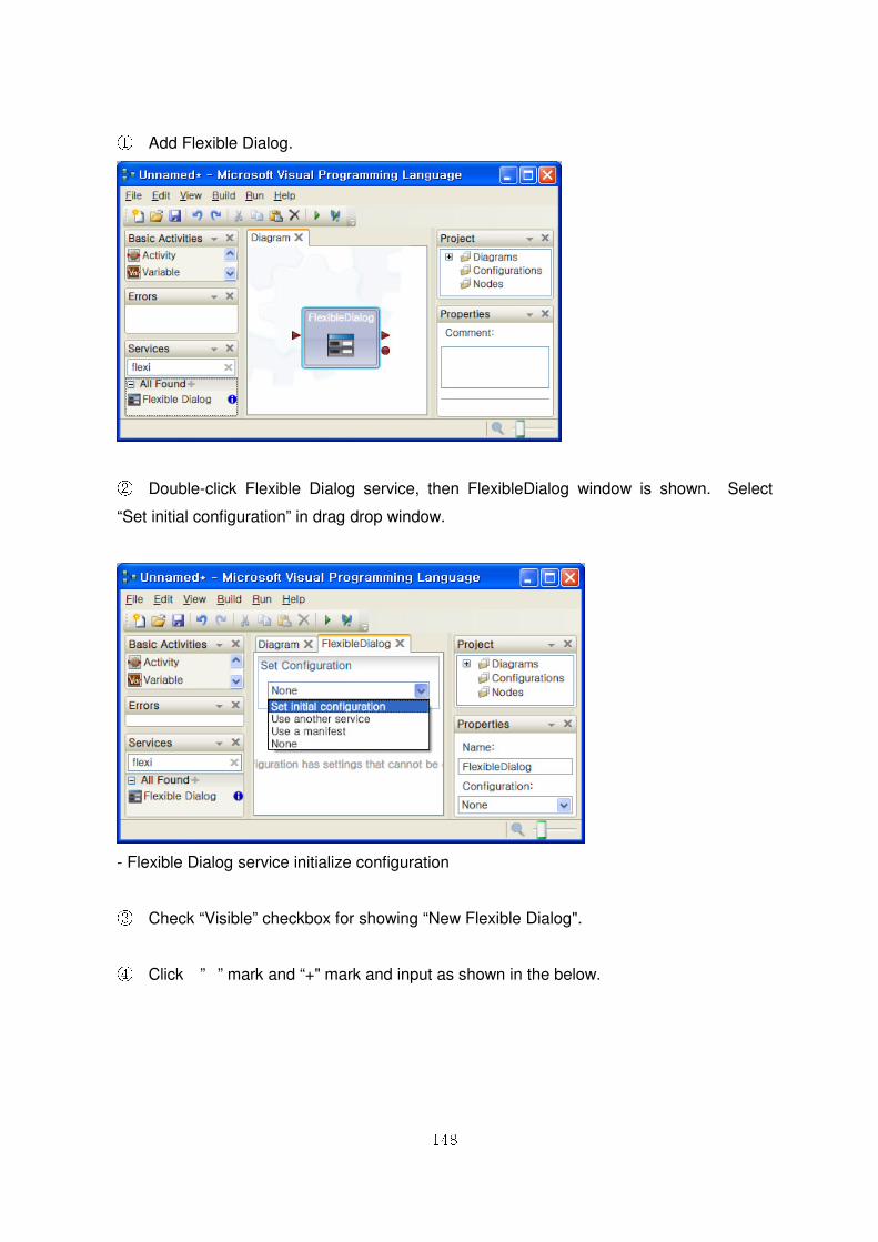
148
① Add Flexible Dialog.
② Double-click Flexible Dialog service, then FlexibleDialog window is shown. Select
“Set initial configuration” in drag drop window.
- Flexible Dialog service initialize configuration
③ Check “Visible” checkbox for showing “New Flexible Dialog".
④ Click ”� ” mark and “+" mark and input as shown in the below.
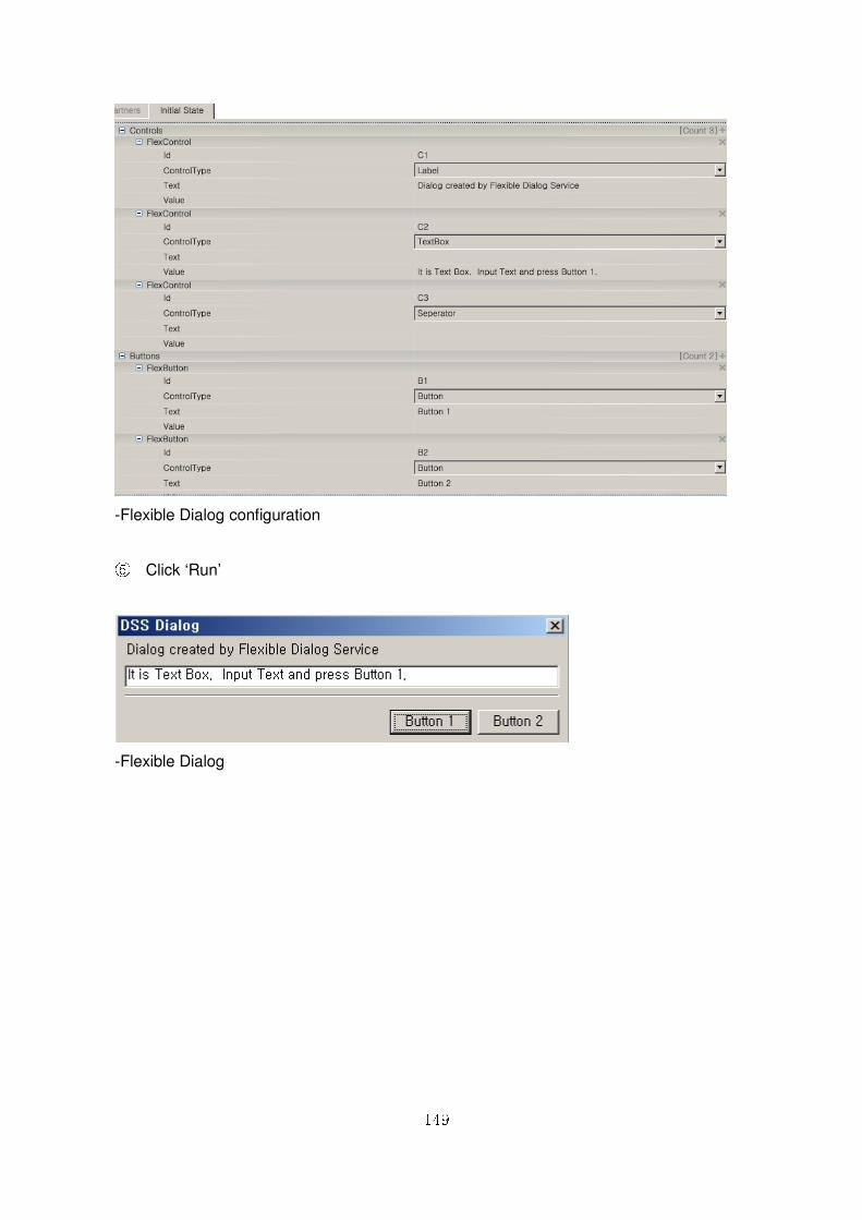
149
-Flexible Dialog configuration
⑤ Click ‘Run’
-Flexible Dialog
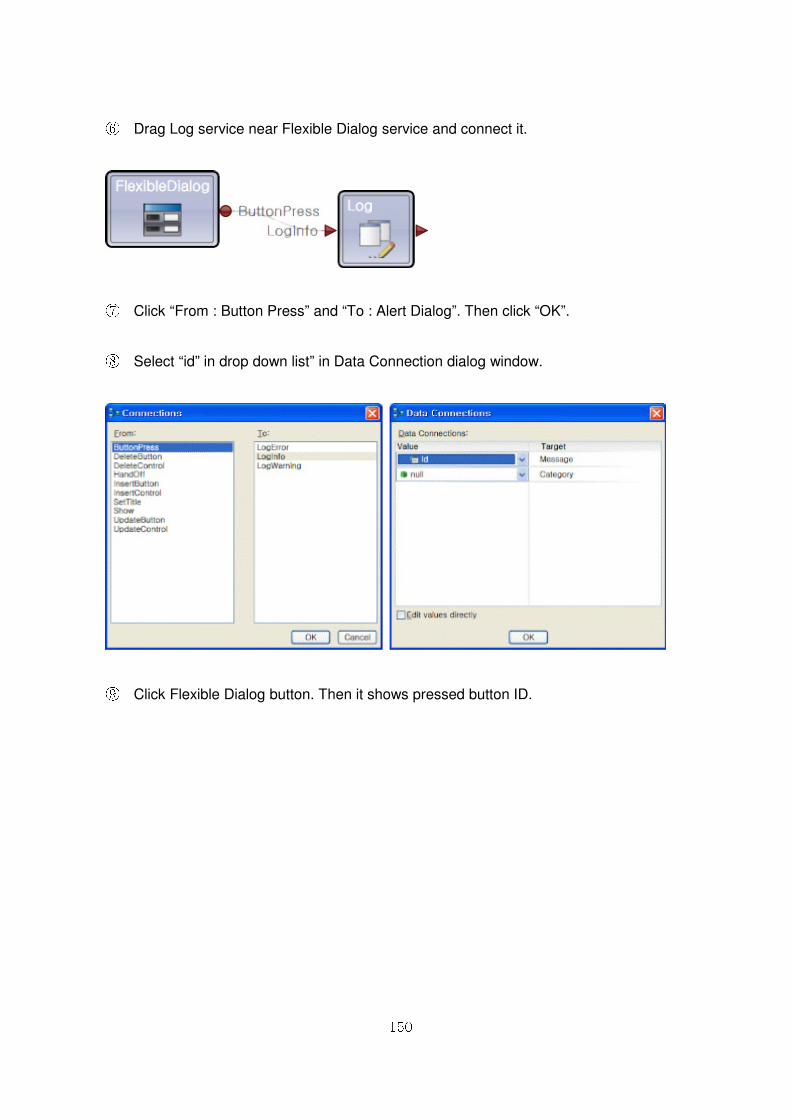
150
⑥ Drag Log service near Flexible Dialog service and connect it.
⑦ Click “From : Button Press” and “To : Alert Dialog”. Then click “OK”.
⑧ Select “id” in drop down list” in Data Connection dialog window.
⑨ Click Flexible Dialog button. Then it shows pressed button ID.
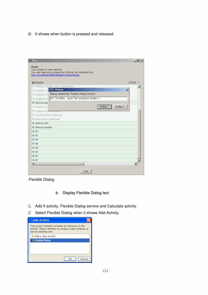
151
⑩ It shows when button is pressed and released.
-Flexible Dialog
bb.. DDiissppllaayy FFlleexxiibbllee DDiiaalloogg tteexxtt
① Add If activity, Flexible Dialog service and Calculate activity. ② Select Flexible Dialog when it shows Add Activity.
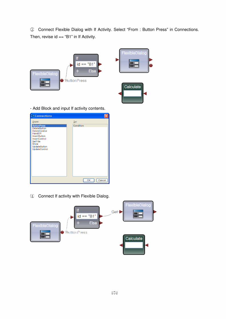
152
③ Connect Flexible Dialog with If Activity. Select “From : Button Press” in Connections.
Then, revise id == “B1” in If Activity.
- Add Block and input If activity contents.
④ Connect If activity with Flexible Dialog.
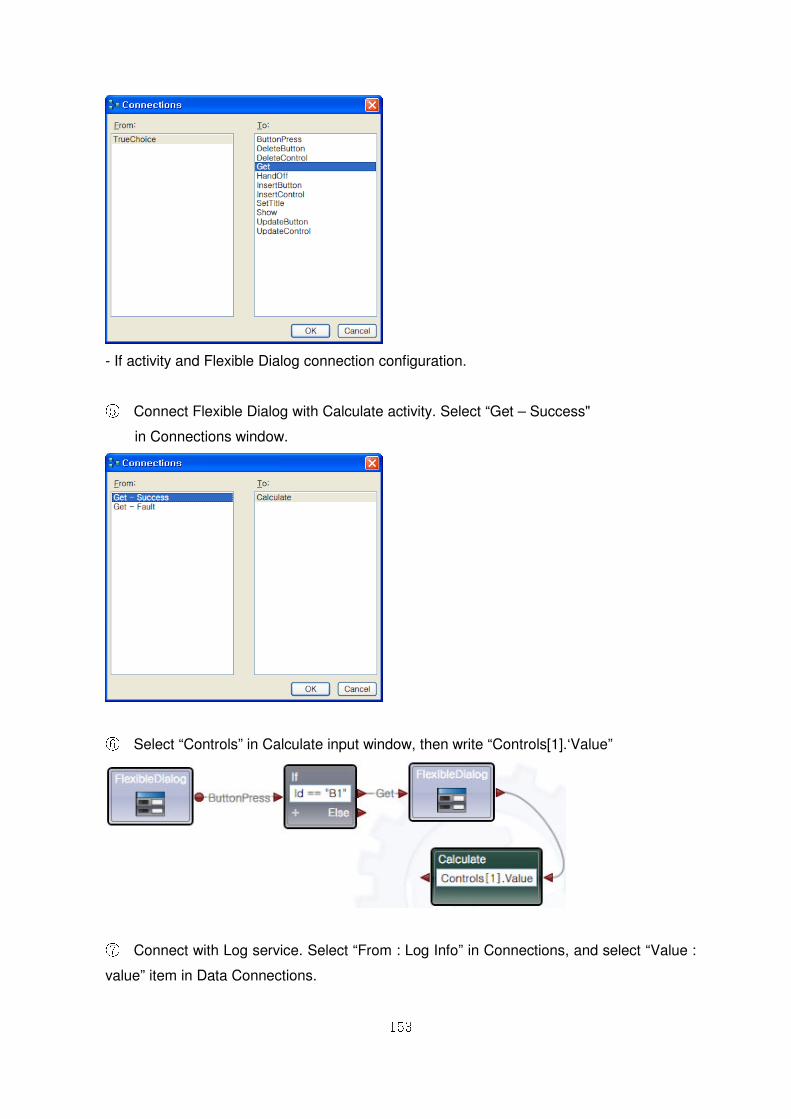
153
- If activity and Flexible Dialog connection configuration.
⑤ Connect Flexible Dialog with Calculate activity. Select “Get – Success"
in Connections window.
⑥ Select “Controls” in Calculate input window, then write “Controls[1].‘Value”
⑦ Connect with Log service. Select “From : Log Info” in Connections, and select “Value :
value” item in Data Connections.
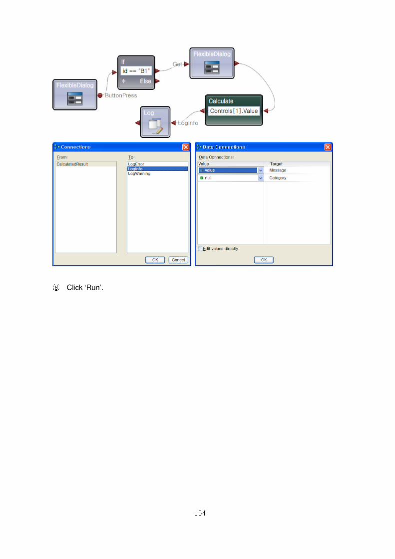
154
⑧ Click ‘Run’.
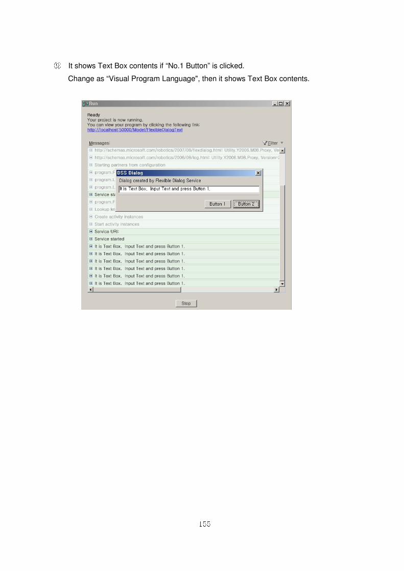
155
⑨ It shows Text Box contents if “No.1 Button” is clicked.
Change as “Visual Program Language", then it shows Text Box contents.
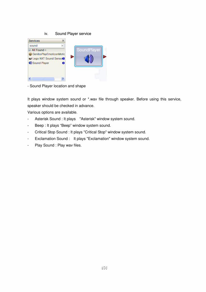
156
iivv.. SSoouunndd PPllaayyeerr sseerrvviiccee
- Sound Player location and shape
It plays window system sound or *.wav file through speaker. Before using this service,
speaker should be checked in advance.
Various options are available.
- Asterisk Sound : It plays "Asterisk" window system sound.
- Beep : It plays “Beep” window system sound.
- Critical Stop Sound : It plays "Critical Stop" window system sound.
- Exclamation Sound : It plays "Exclamation" window system sound.
- Play Sound : Play wav files.
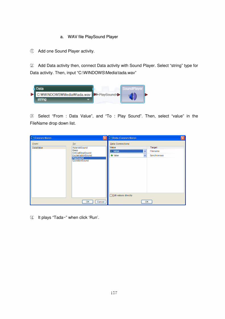
157
aa.. WWAAVV ffiillee PPllaayySSoouunndd PPllaayyeerr
① Add one Sound Player activity.
② Add Data activity then, connect Data activity with Sound Player. Select “string” type for
Data activity. Then, input “C:\WINDOWS\Media\tada.wav”
③ Select “From : Data Value”, and “To : Play Sound”. Then, select “value” in the
FileName drop down list.
④ It plays “Tada~” when click ‘Run’.
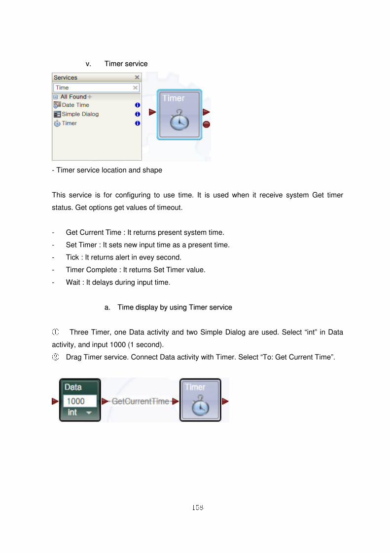
158
vv.. TTiimmeerr sseerrvviiccee
- Timer service location and shape
This service is for configuring to use time. It is used when it receive system Get timer
status. Get options get values of timeout.
- Get Current Time : It returns present system time.
- Set Timer : It sets new input time as a present time.
- Tick : It returns alert in evey second.
- Timer Complete : It returns Set Timer value.
- Wait : It delays during input time.
aa.. TTiimmee ddiissppllaayy bbyy uussiinngg TTiimmeerr sseerrvviiccee
① Three Timer, one Data activity and two Simple Dialog are used. Select “int” in Data
activity, and input 1000 (1 second). ② Drag Timer service. Connect Data activity with Timer. Select “To: Get Current Time”.
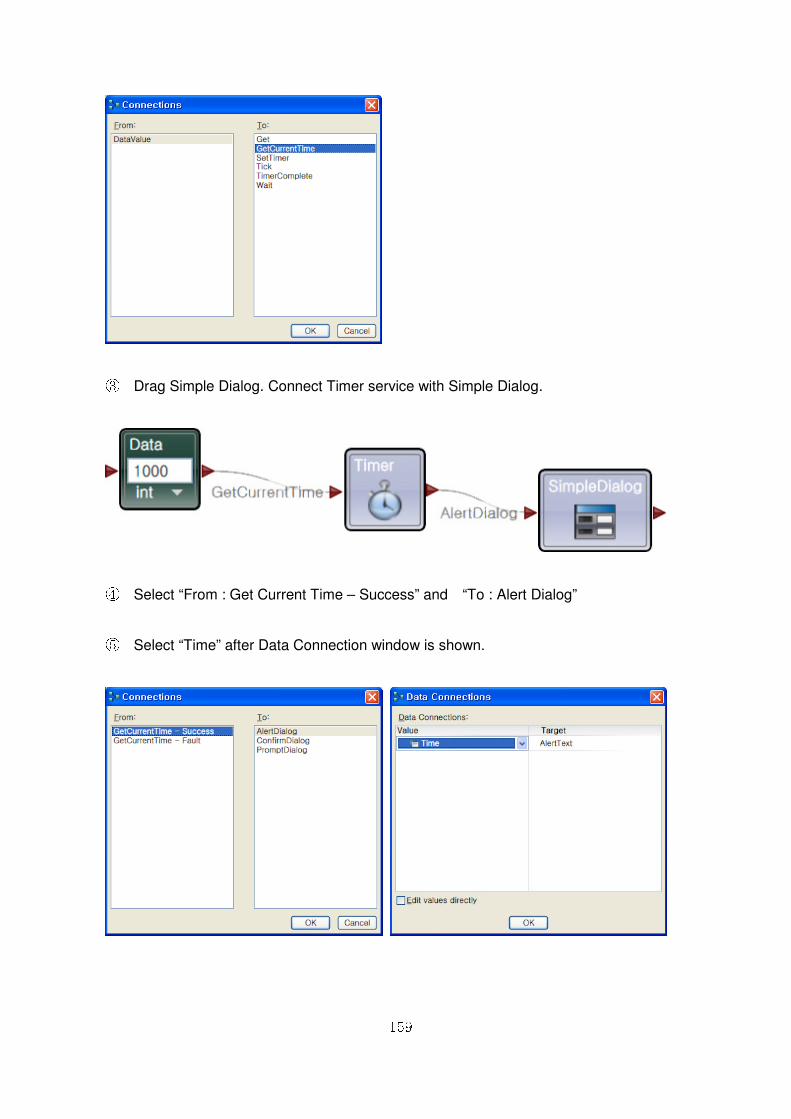
159
③ Drag Simple Dialog. Connect Timer service with Simple Dialog.
④ Select “From : Get Current Time – Success” and “To : Alert Dialog”
⑤ Select “Time” after Data Connection window is shown.
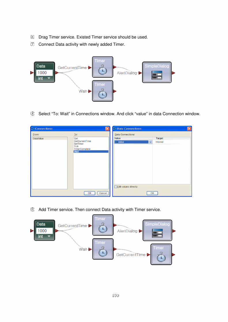
160
⑥ Drag Timer service. Existed Timer service should be used. ⑦ Connect Data activity with newly added Timer.
⑧ Select “To: Wait” in Connections window. And click “value” in data Connection window.
⑨ Add Timer service. Then connect Data activity with Timer service.
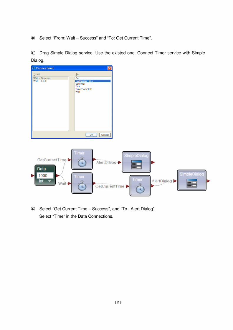
161
⑩ Select “From: Wait – Success” and “To: Get Current Time”.
⑪ Drag Simple Dialog service. Use the existed one. Connect Timer service with Simple
Dialog.
⑫ Select “Get Current Time – Success”, and “To : Alert Dialog”.
Select “Time” in the Data Connections.
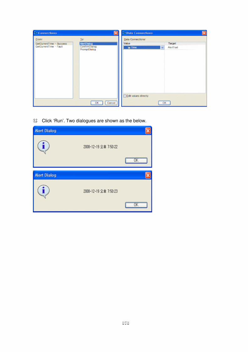
162
⑬ Click ‘Run’. Two dialogues are shown as the below.
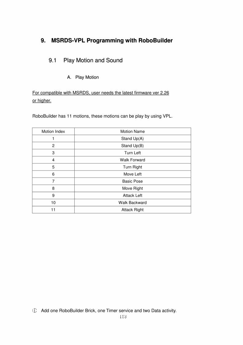
163
99.. MMSSRRDDSS--VVPPLL PPrrooggrraammmmiinngg wwiitthh RRoobbooBBuuiillddeerr
99..11 PPllaayy MMoottiioonn aanndd SSoouunndd
AA.. PPllaayy MMoottiioonn
For compatible with MSRDS, user needs the latest firmware ver 2.26
or higher.
RoboBuilder has 11 motions, these motions can be play by using VPL.
① Add one RoboBuilder Brick, one Timer service and two Data activity.
Motion Index Motion Name
1 Stand Up(A)
2 Stand Up(B)
3 Turn Left
4 Walk Forward
5 Turn Right
6 Move Left
7 Basic Pose
8 Move Right
9 Attack Left
10 Walk Backward
11 Attack Right
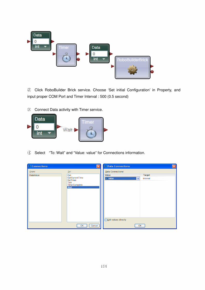
164
② Click RoboBuilder Brick service. Choose ‘Set initial Configuration’ in Property, and
input proper COM Port and Timer Interval : 500 (0.5 second)
③ Connect Data activity with Timer service.
④ Select “To: Wait” and “Value: value” for Connections information.
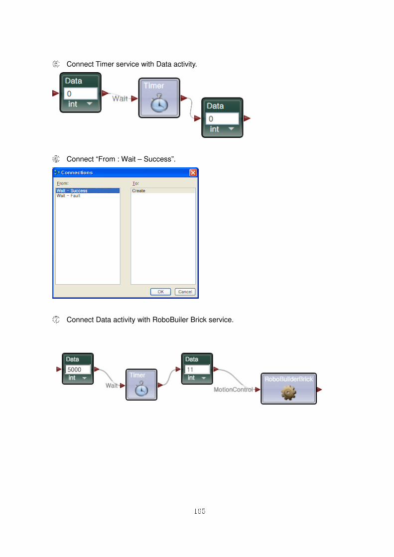
165
⑤ Connect Timer service with Data activity.
⑥ Connect “From : Wait – Success”.
⑦ Connect Data activity with RoboBuiler Brick service.
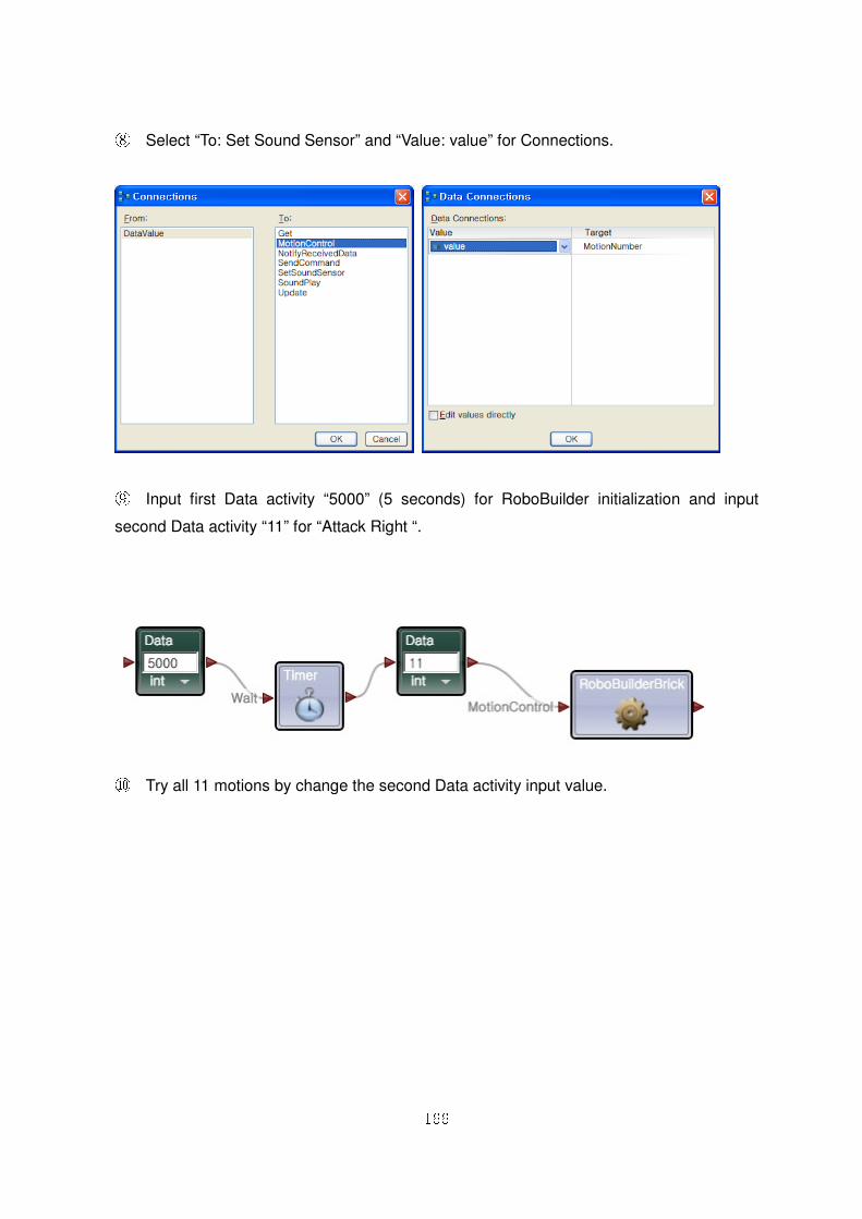
166
⑧ Select “To: Set Sound Sensor” and “Value: value” for Connections.
⑨ Input first Data activity “5000” (5 seconds) for RoboBuilder initialization and input
second Data activity “11” for “Attack Right “.
⑩ Try all 11 motions by change the second Data activity input value.
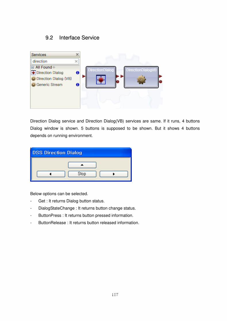
167
99..22 IInntteerrffaaccee SSeerrvviiccee
Direction Dialog service and Direction Dialog(VB) services are same. If it runs, 4 buttons
Dialog window is shown. 5 buttons is supposed to be shown. But it shows 4 buttons
depends on running environment.
Below options can be selected.
- Get : It returns Dialog button status.
- DialogStateChange : It returns button change status.
- ButtonPress : It returns button pressed information.
- ButtonRelease : It returns button released information.
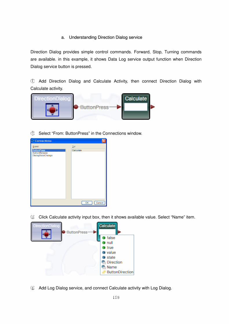
168
aa.. UUnnddeerrssttaannddiinngg DDiirreeccttiioonn DDiiaalloogg sseerrvviiccee
Direction Dialog provides simple control commands. Forward, Stop, Turning commands
are available. in this example, it shows Data Log service output function when Direction
Dialog service button is pressed.
① Add Direction Dialog and Calculate Activity, then connect Direction Dialog with
Calculate activity.
② Select “From: ButtonPress” in the Connections window.
③ Click Calculate activity input box, then it shows available value. Select “Name” item.
④ Add Log Dialog service, and connect Calculate activity with Log Dialog.
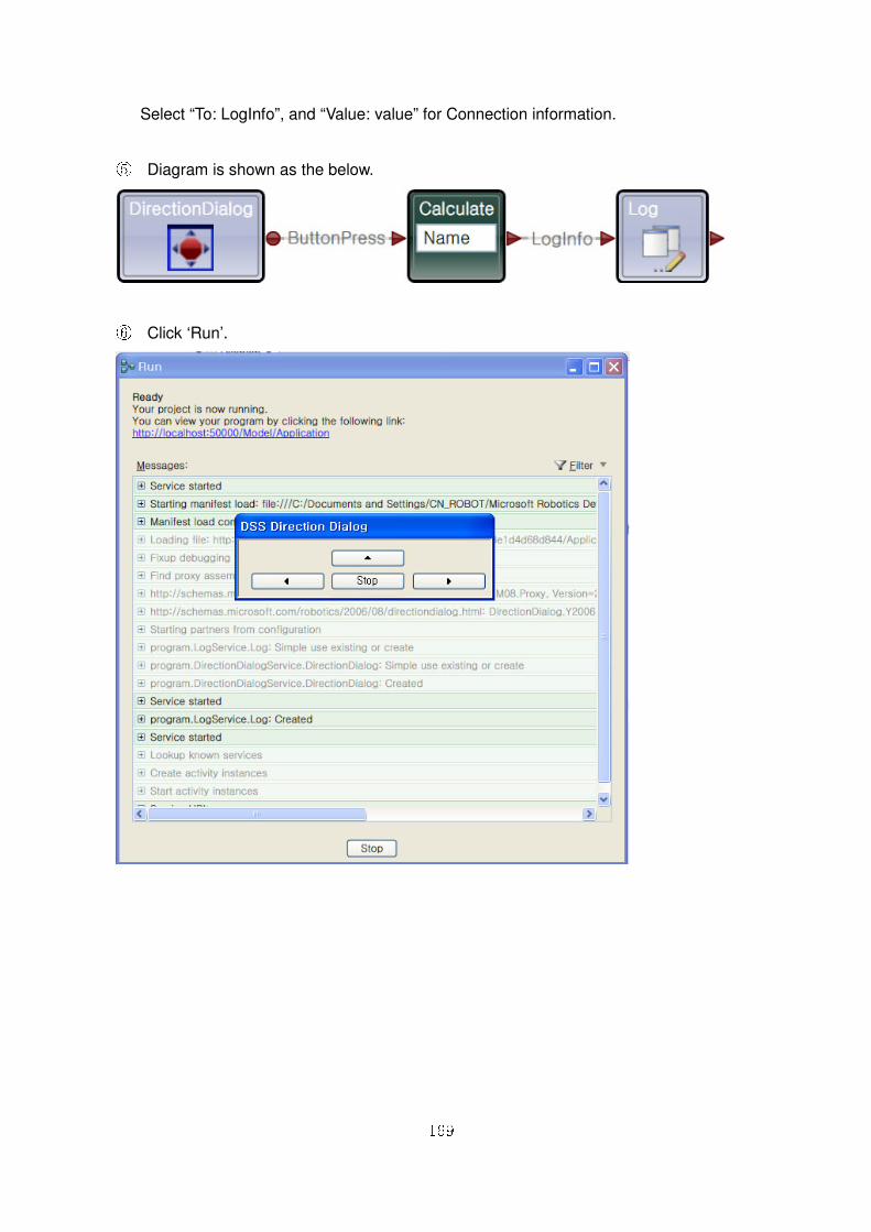
169
Select “To: LogInfo”, and “Value: value” for Connection information.
⑤ Diagram is shown as the below.
⑥ Click ‘Run’.
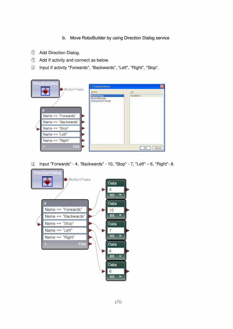
170
bb.. MMoovvee RRoobbooBBuuiillddeerr bbyy uussiinngg DDiirreeccttiioonn DDiiaalloogg sseerrvviiccee
① Add Direction Dialog. ② Add If activity and connect as below. ③ Input If activity "Forwards", “Backwards", “Left", "Right", "Stop".
④ Input "Forwards" - 4, “Backwards" - 10, "Stop" - 7, "Left" – 6, "Right"- 8.
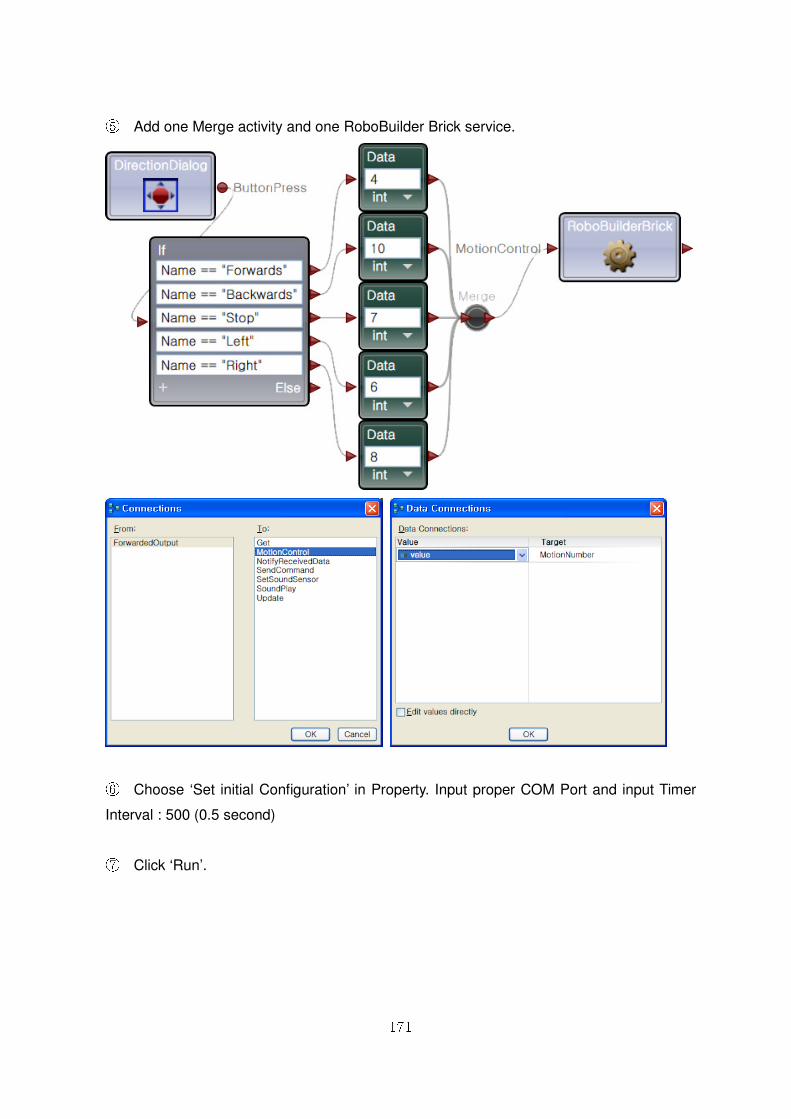
171
⑤ Add one Merge activity and one RoboBuilder Brick service.
⑥ Choose ‘Set initial Configuration’ in Property. Input proper COM Port and input Timer
Interval : 500 (0.5 second)
⑦ Click ‘Run’.
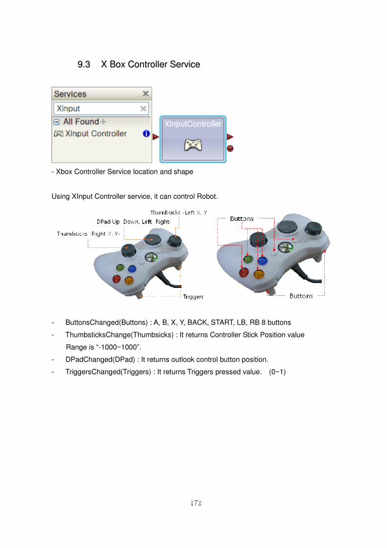
172
99..33 XX BBooxx CCoonnttrroolllleerr SSeerrvviiccee
- Xbox Controller Service location and shape
Using XInput Controller service, it can control Robot.
- ButtonsChanged(Buttons) : A, B, X, Y, BACK, START, LB, RB 8 buttons
- ThumbsticksChange(Thumbsicks) : It returns Controller Stick Position value
Range is “-1000~1000”.
- DPadChanged(DPad) : It returns outlook control button position.
- TriggersChanged(Triggers) : It returns Triggers pressed value. (0~1)
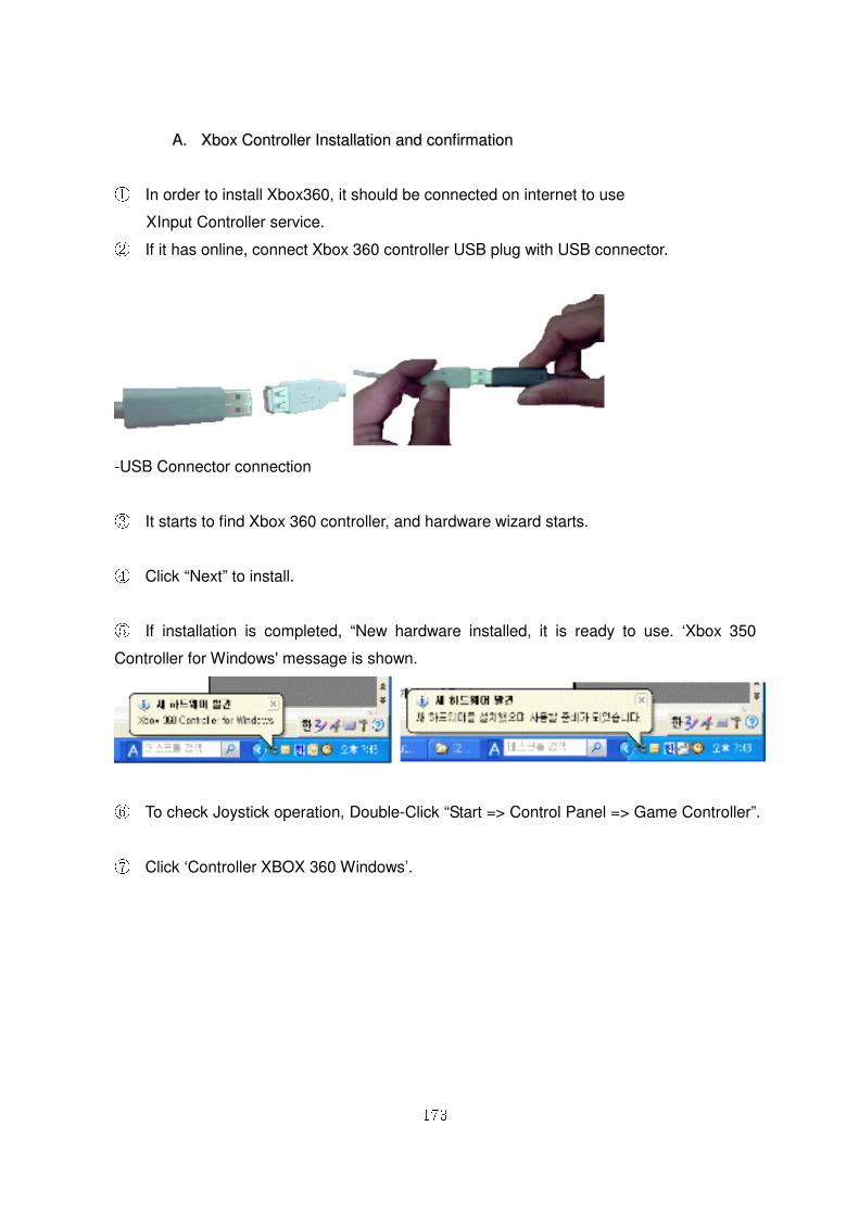
173
AA.. XXbbooxx CCoonnttrroolllleerr IInnssttaallllaattiioonn aanndd ccoonnffiirrmmaattiioonn
① In order to install Xbox360, it should be connected on internet to use
XInput Controller service. ② If it has online, connect Xbox 360 controller USB plug with USB connector.
-USB Connector connection
③ It starts to find Xbox 360 controller, and hardware wizard starts.
④ Click “Next” to install.
⑤ If installation is completed, “New hardware installed, it is ready to use. ‘Xbox 350
Controller for Windows' message is shown.
⑥ To check Joystick operation, Double-Click “Start => Control Panel => Game Controller”.
⑦ Click ‘Controller XBOX 360 Windows’.
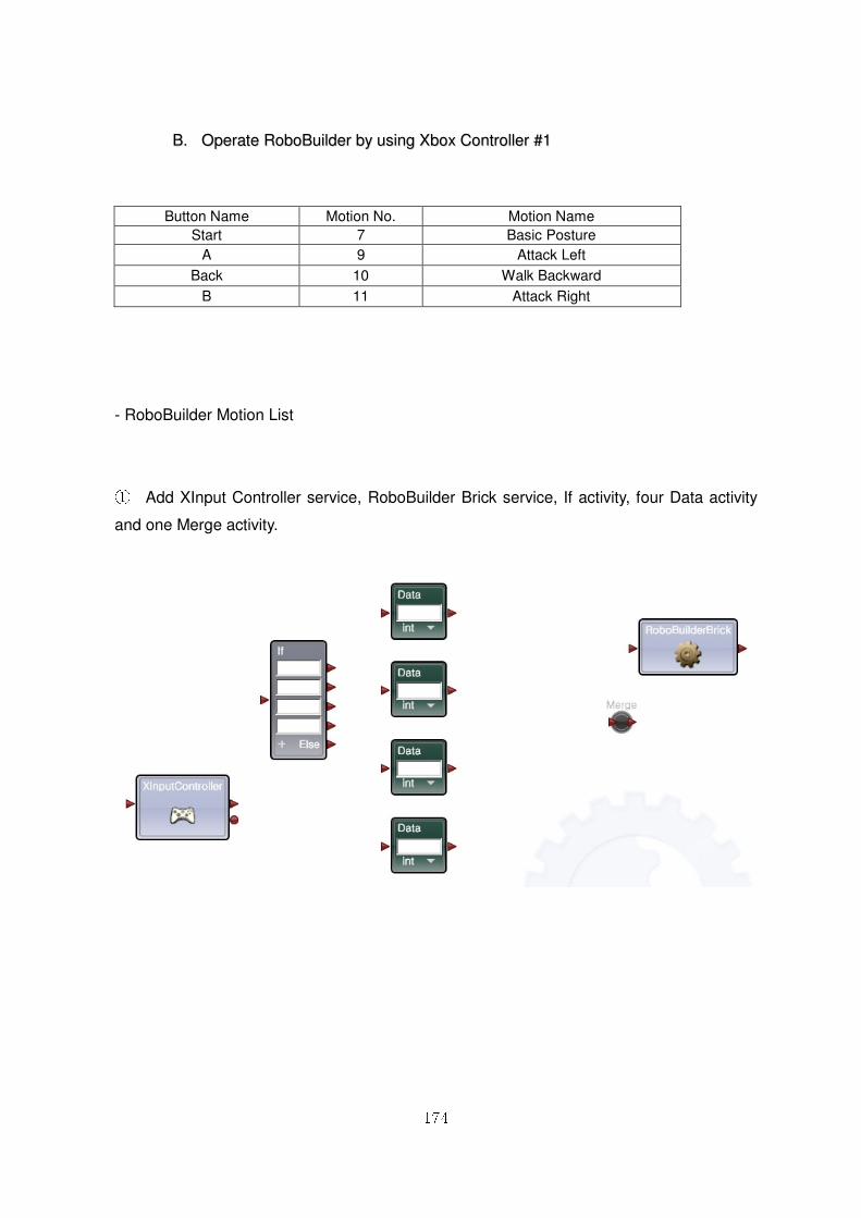
174
BB.. OOppeerraattee RRoobbooBBuuiillddeerr bbyy uussiinngg XXbbooxx CCoonnttrroolllleerr ##11
- RoboBuilder Motion List
① Add XInput Controller service, RoboBuilder Brick service, If activity, four Data activity
and one Merge activity.
Button Name Motion No. Motion Name
Start 7 Basic Posture
A 9 Attack Left
Back 10 Walk Backward
B 11 Attack Right
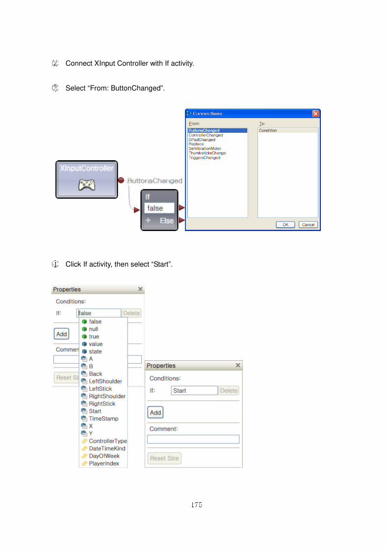
175
② Connect XInput Controller with If activity.
③ Select “From: ButtonChanged”.
④ Click If activity, then select “Start”.
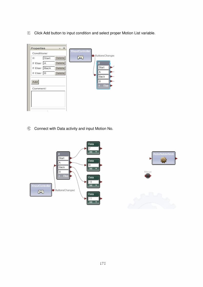
176
⑤ Click Add button to input condition and select proper Motion List variable.
⑥ Connect with Data activity and input Motion No.
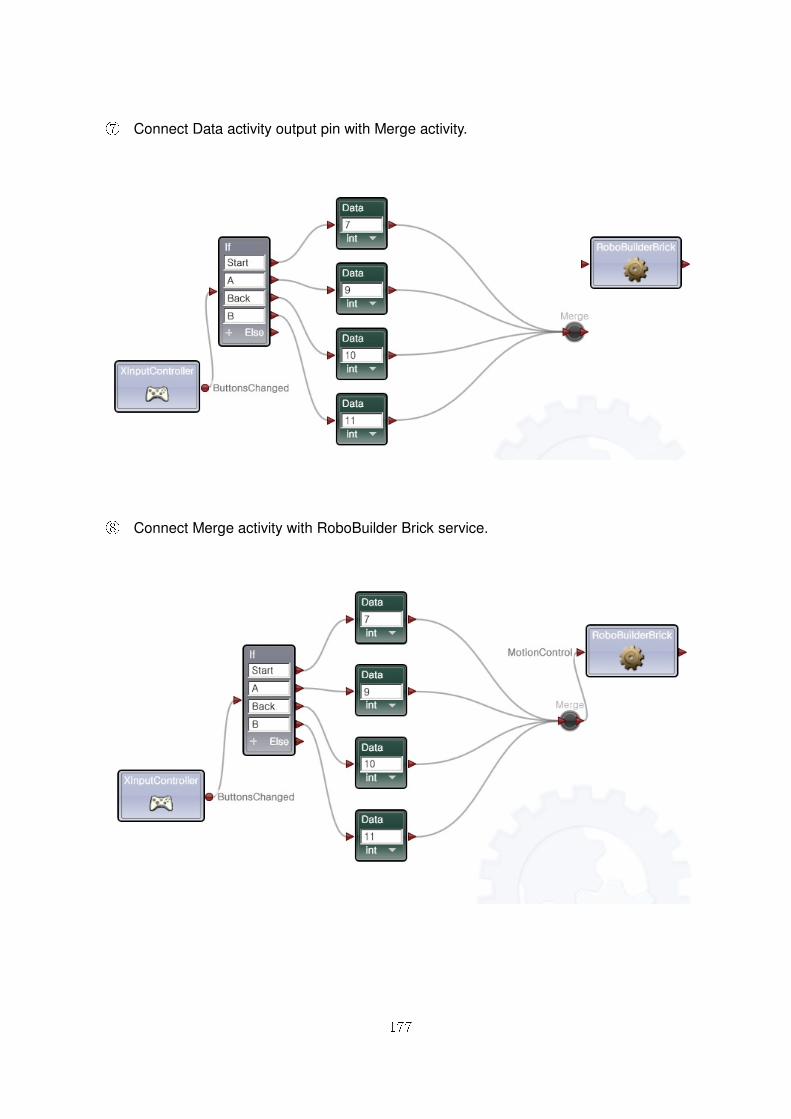
177
⑦ Connect Data activity output pin with Merge activity.
⑧ Connect Merge activity with RoboBuilder Brick service.
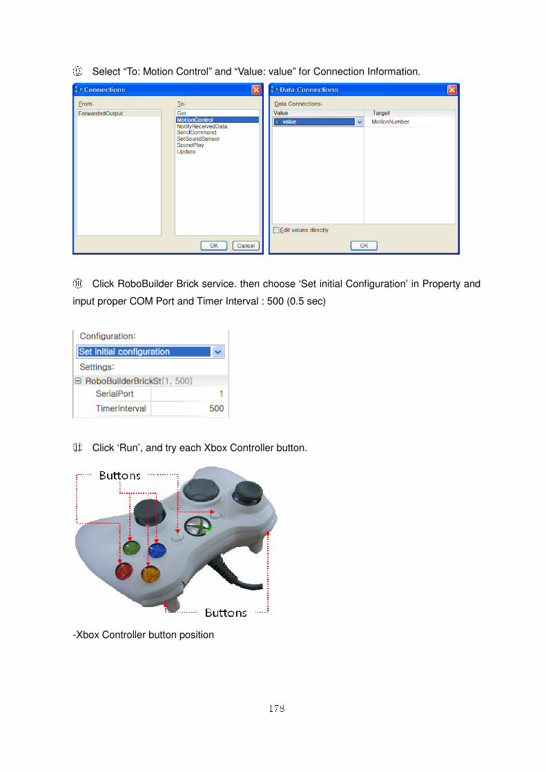
178
⑨ Select “To: Motion Control” and “Value: value” for Connection Information.
⑩ Click RoboBuilder Brick service. then choose ‘Set initial Configuration’ in Property and
input proper COM Port and Timer Interval : 500 (0.5 sec)
⑪ Click ‘Run’, and try each Xbox Controller button.
-Xbox Controller button position
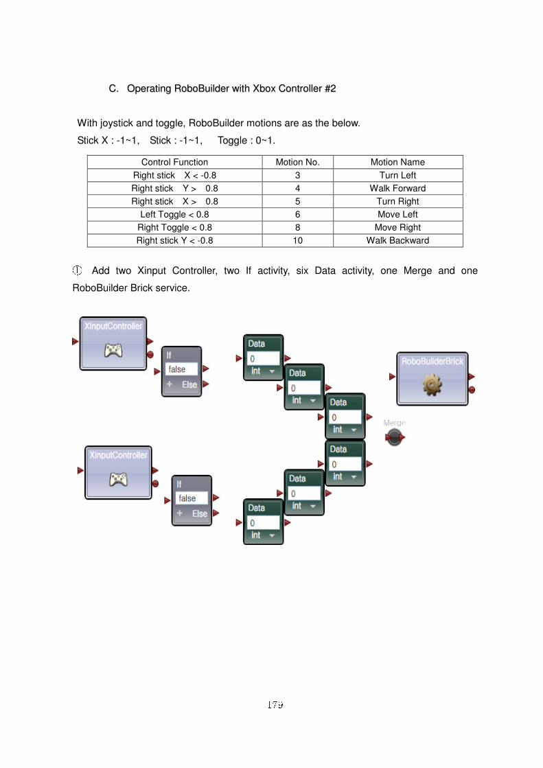
179
CC.. OOppeerraattiinngg RRoobbooBBuuiillddeerr wwiitthh XXbbooxx CCoonnttrroolllleerr ##22
With joystick and toggle, RoboBuilder motions are as the below.
Stick X : -1~1, Stick : -1~1, Toggle : 0~1.
① Add two Xinput Controller, two If activity, six Data activity, one Merge and one
RoboBuilder Brick service.
Control Function Motion No. Motion Name
Right stick X < -0.8 3 Turn Left
Right stick Y > 0.8 4 Walk Forward
Right stick X > 0.8 5 Turn Right
Left Toggle < 0.8 6 Move Left
Right Toggle < 0.8 8 Move Right
Right stick Y < -0.8 10 Walk Backward
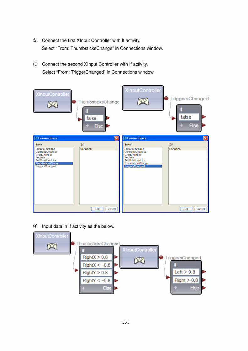
180
② Connect the first XInput Controller with If activity.
Select “From: ThumbsticksChange” in Connections window.
③ Connect the second XInput Controller with If activity.
Select “From: TriggerChanged” in Connections window.
④ Input data in If activity as the below.
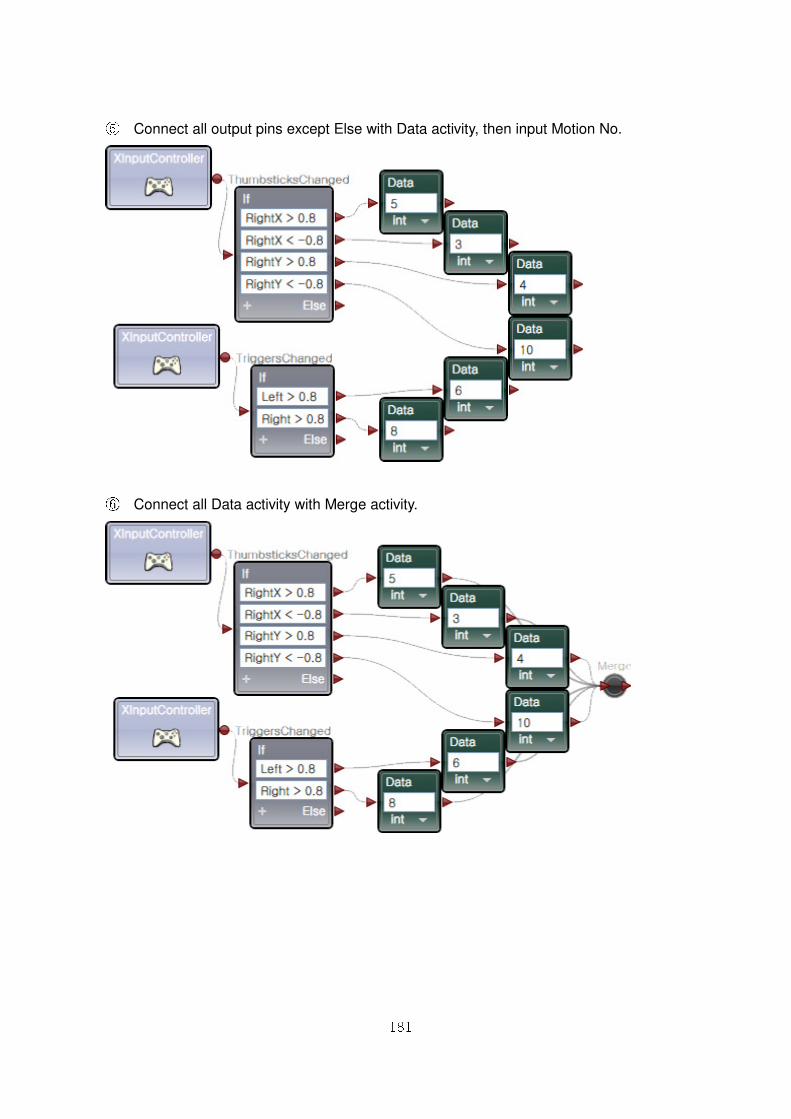
181
⑤ Connect all output pins except Else with Data activity, then input Motion No.
⑥⑥ Connect all Data activity with Merge activity.
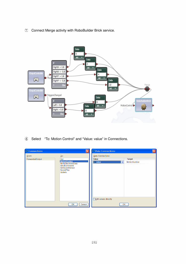
182
⑦ Connect Merge activity with RoboBuilder Brick service.
⑧ Select “To: Motion Control” and “Value: value” in Connections.
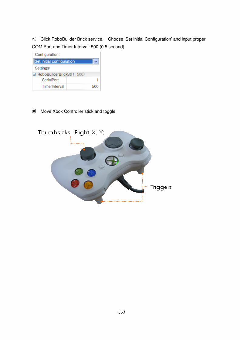
183
⑨ Click RoboBuilder Brick service. Choose ‘Set initial Configuration’ and input proper
COM Port and Timer Interval: 500 (0.5 second).
⑩ Move Xbox Controller stick and toggle.
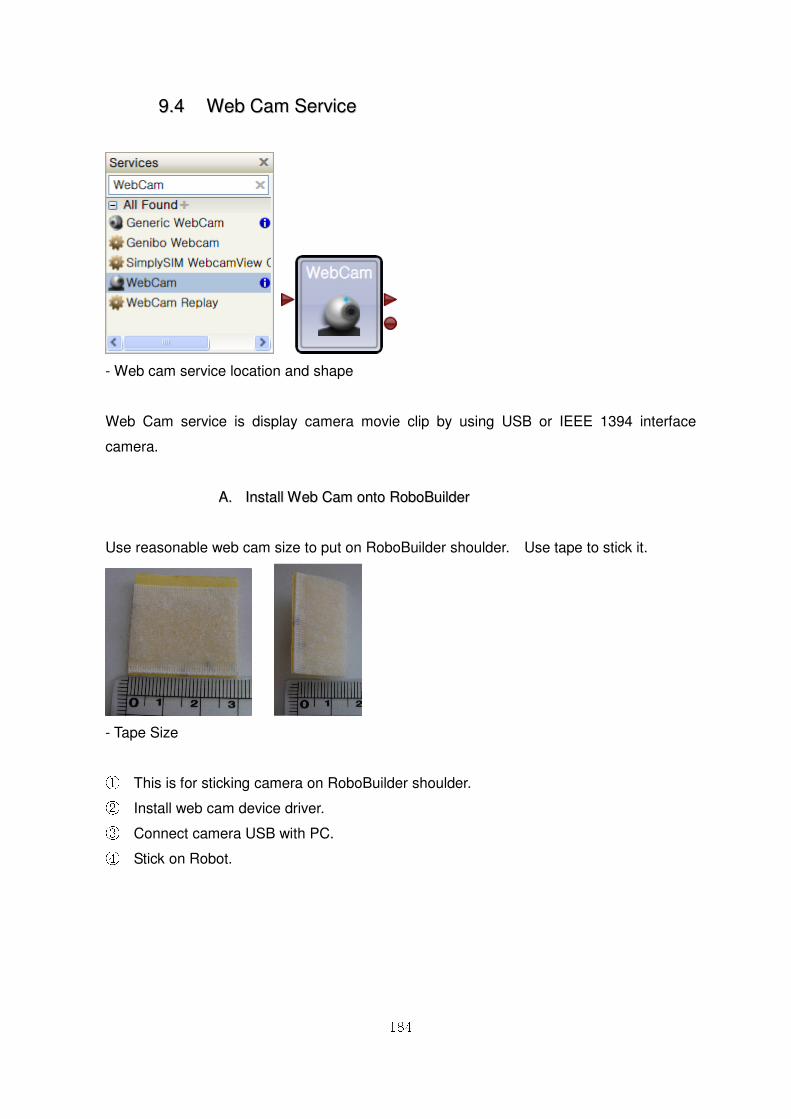
184
99..44 WWeebb CCaamm SSeerrvviiccee
- Web cam service location and shape
Web Cam service is display camera movie clip by using USB or IEEE 1394 interface
camera.
AA.. IInnssttaallll WWeebb CCaamm oonnttoo RRoobbooBBuuiillddeerr
Use reasonable web cam size to put on RoboBuilder shoulder. Use tape to stick it.
- Tape Size
① This is for sticking camera on RoboBuilder shoulder. ② Install web cam device driver. ③ Connect camera USB with PC. ④ Stick on Robot.
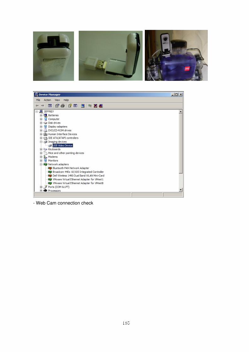
185
- Web Cam connection check
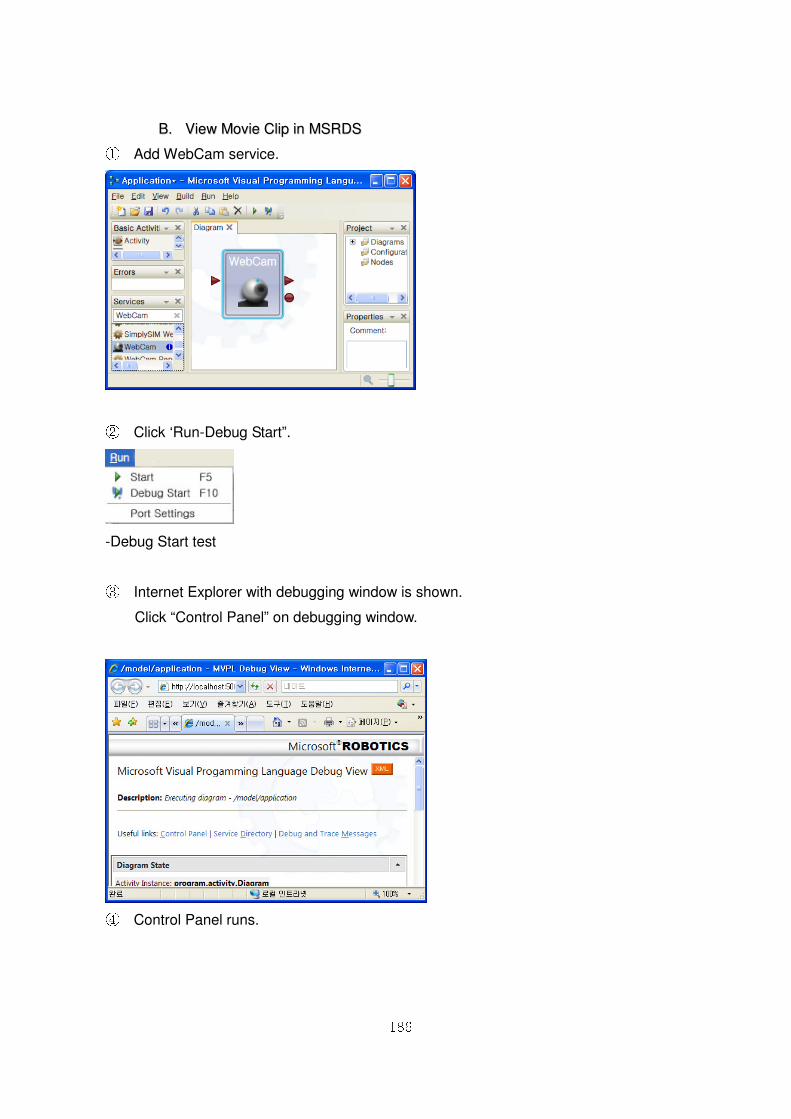
186
BB.. VViieeww MMoovviiee CClliipp iinn MMSSRRDDSS ① Add WebCam service.
② Click ‘Run-Debug Start”.
-Debug Start test
③ Internet Explorer with debugging window is shown.
Click “Control Panel” on debugging window.
④ Control Panel runs.
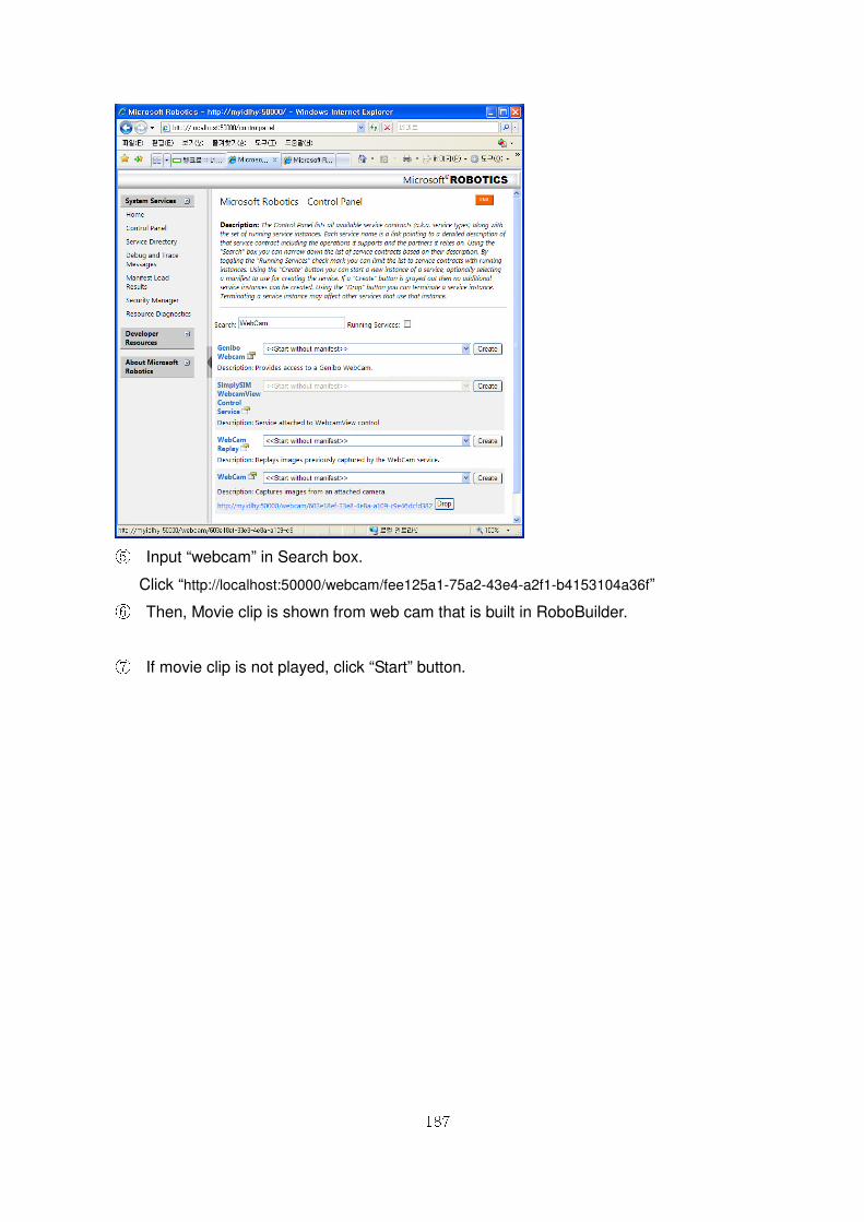
187
⑤ Input “webcam” in Search box.
Click “http://localhost:50000/webcam/fee125a1-75a2-43e4-a2f1-b4153104a36f” ⑥ Then, Movie clip is shown from web cam that is built in RoboBuilder.
⑦ If movie clip is not played, click “Start” button.
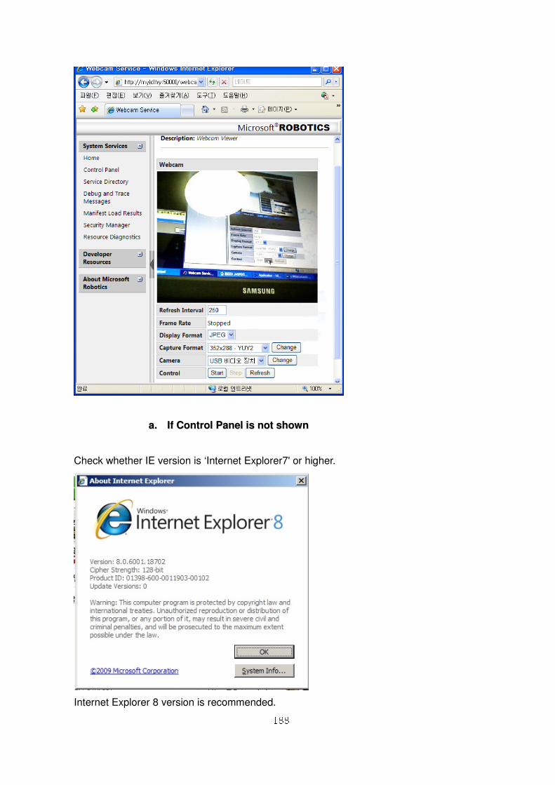
188
aa.. IIff CCoonnttrrooll PPaanneell iiss nnoott sshhoowwnn
Check whether IE version is ‘Internet Explorer7' or higher.
Internet Explorer 8 version is recommended.
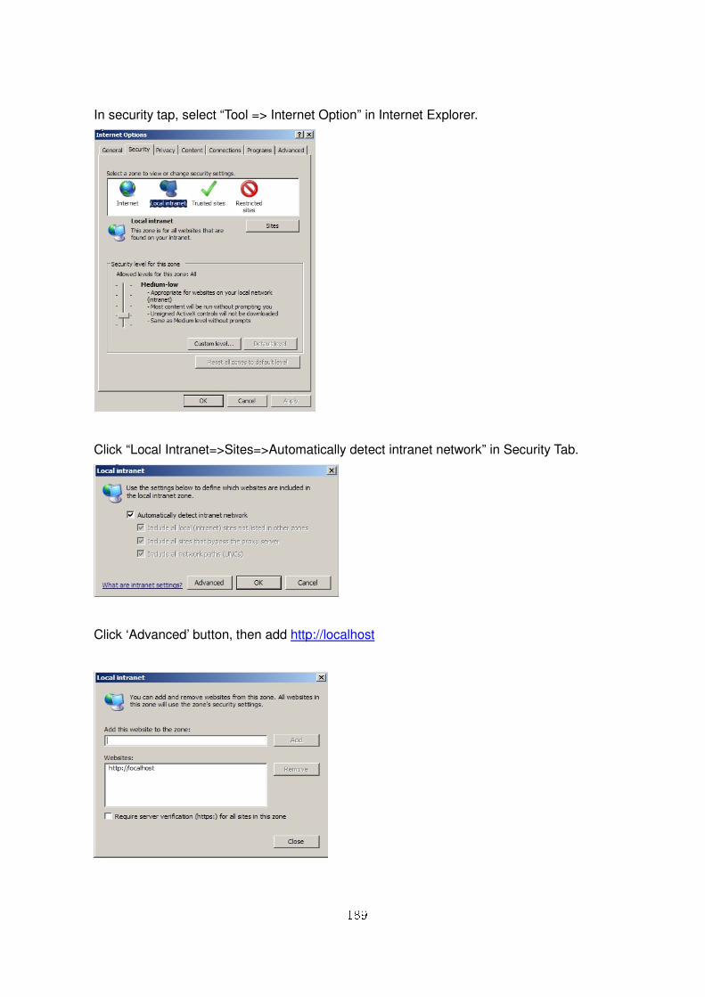
189
In security tap, select “Tool => Internet Option” in Internet Explorer.
Click “Local Intranet=>Sites=>Automatically detect intranet network” in Security Tab.
Click ‘Advanced’ button, then add http://localhost
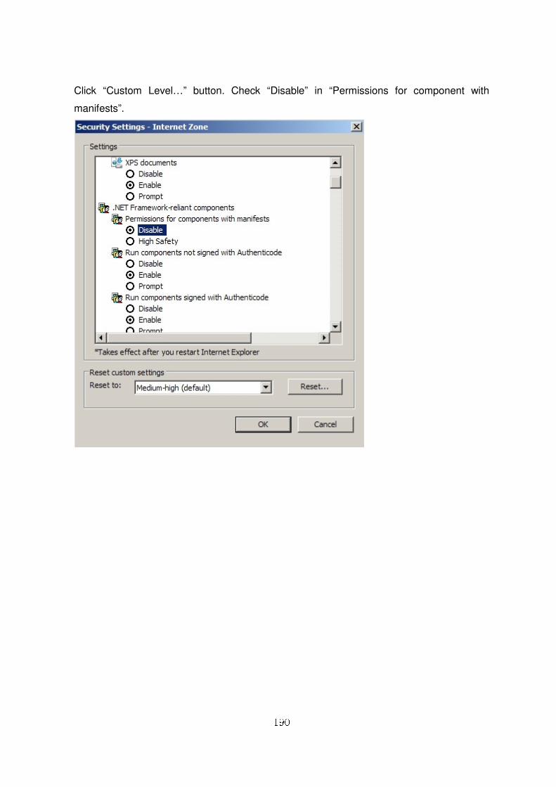
190
Click “Custom Level…” button. Check “Disable” in “Permissions for component with
manifests”.
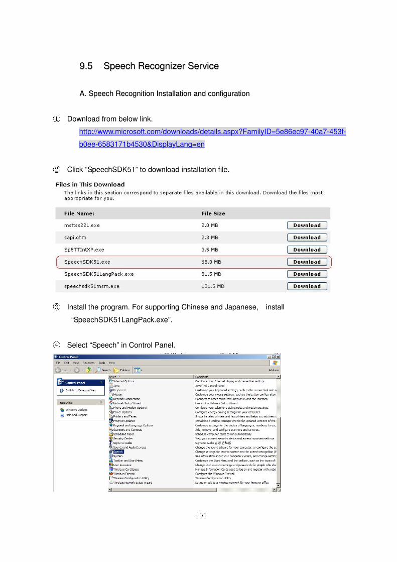
191
99..55 SSppeeeecchh RReeccooggnniizzeerr SSeerrvviiccee
AA.. SSppeeeecchh RReeccooggnniittiioonn IInnssttaallllaattiioonn aanndd ccoonnffiigguurraattiioonn
① Download from below link.
http://www.microsoft.com/downloads/details.aspx?FamilyID=5e86ec97-40a7-453f-
b0ee-6583171b4530&DisplayLang=en
② Click “SpeechSDK51” to download installation file.
③ Install the program. For supporting Chinese and Japanese, install
“SpeechSDK51LangPack.exe”.
④ Select “Speech” in Control Panel.
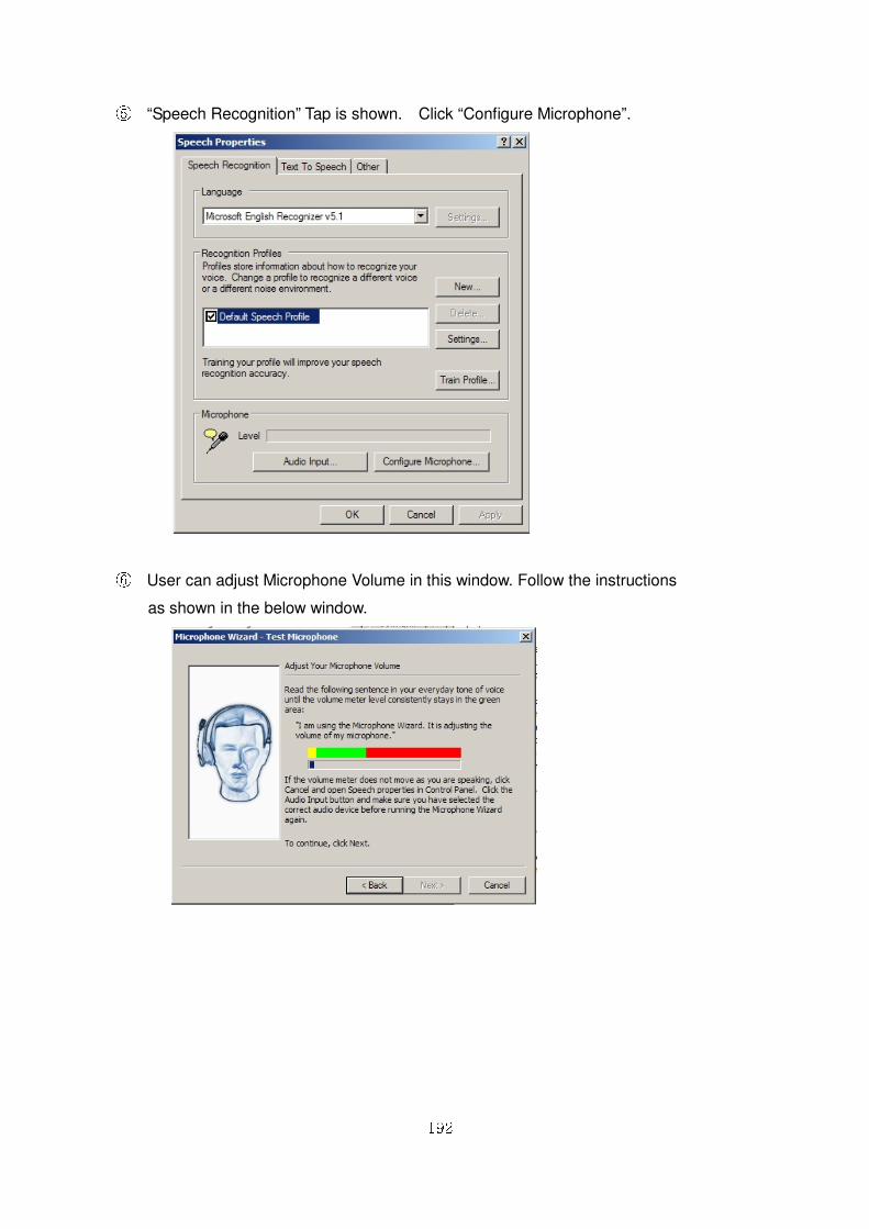
192
⑤ “Speech Recognition” Tap is shown. Click “Configure Microphone”.
⑥ User can adjust Microphone Volume in this window. Follow the instructions
as shown in the below window.
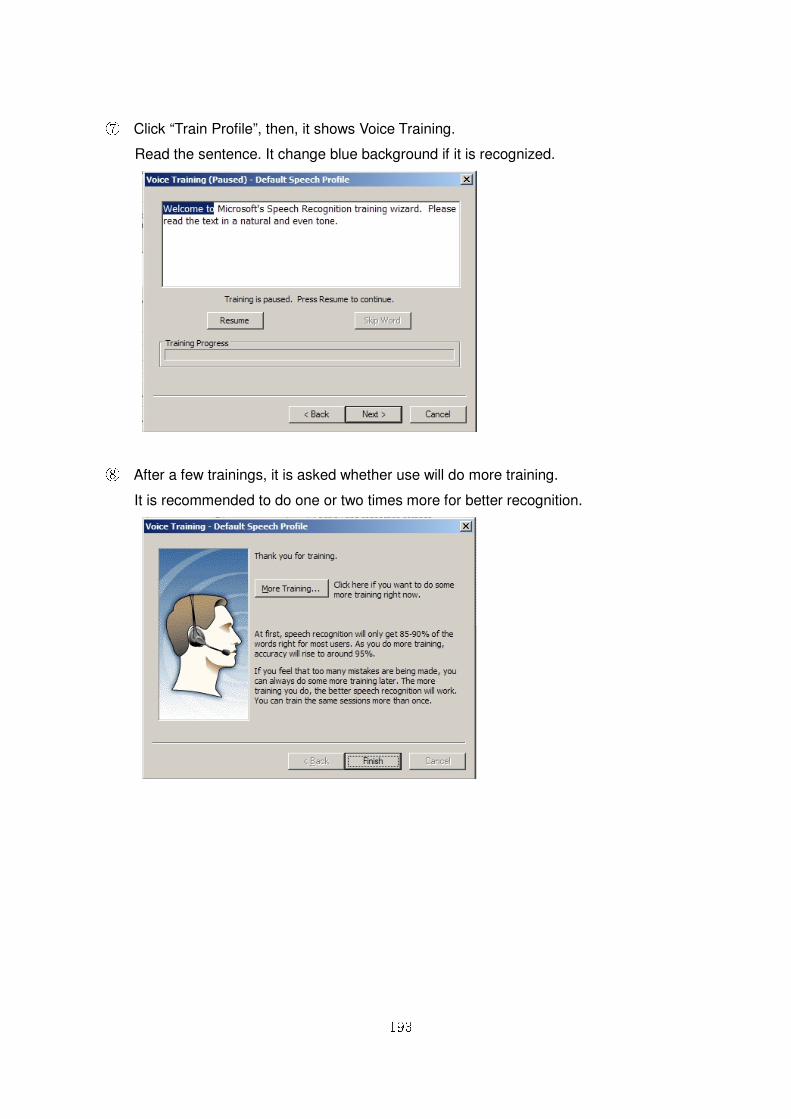
193
⑦ Click “Train Profile”, then, it shows Voice Training.
Read the sentence. It change blue background if it is recognized.
⑧ After a few trainings, it is asked whether use will do more training.
It is recommended to do one or two times more for better recognition.
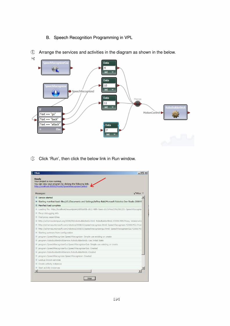
194
BB.. SSppeeeecchh RReeccooggnniittiioonn PPrrooggrraammmmiinngg iinn VVPPLL
①① Arrange the services and activities in the diagram as shown in the below.
② Click ‘Run’, then click the below link in Run window.
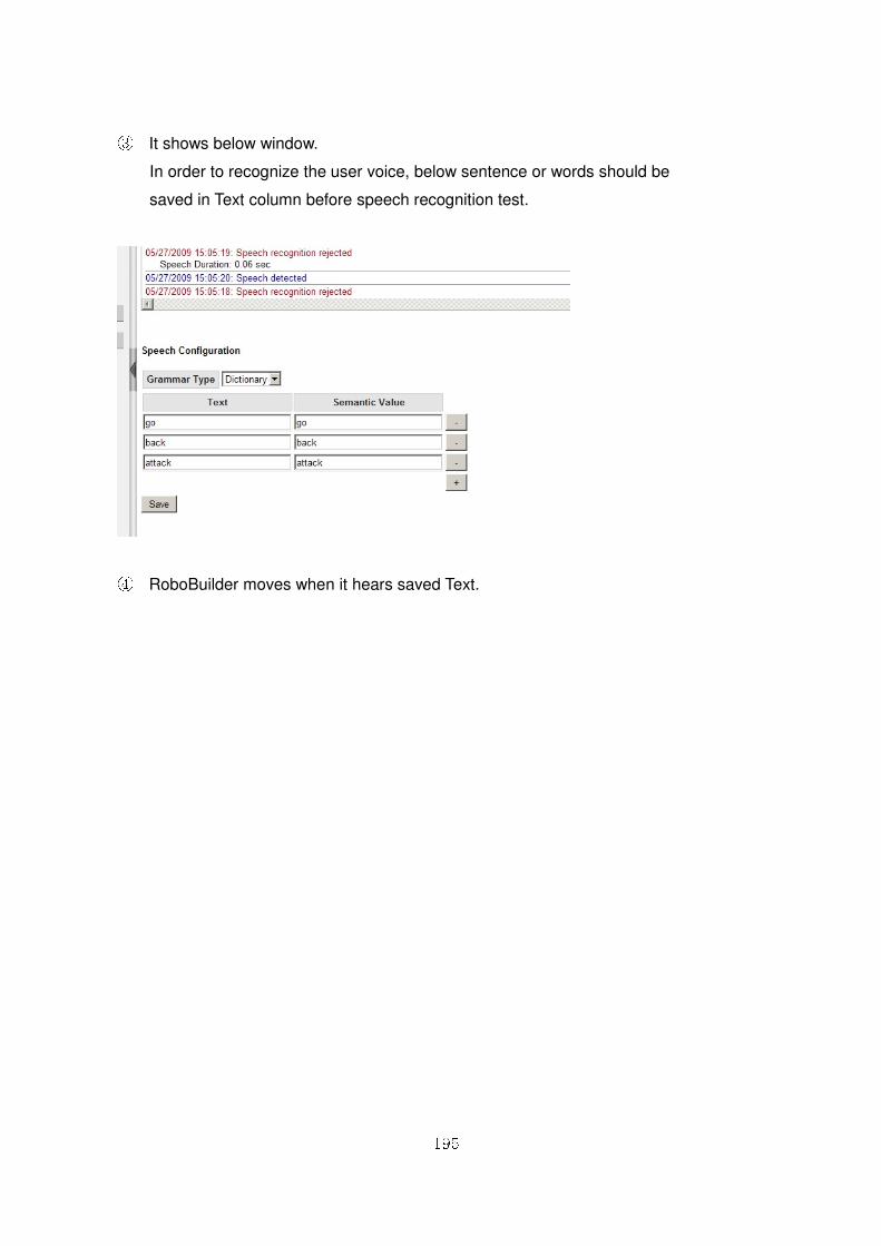
195
③ It shows below window.
In order to recognize the user voice, below sentence or words should be
saved in Text column before speech recognition test.
④ RoboBuilder moves when it hears saved Text.
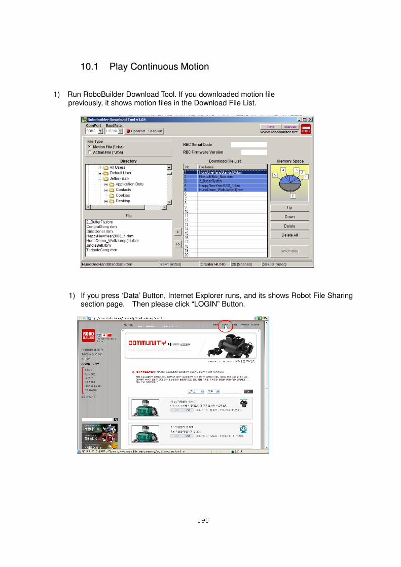
196
1100..11 PPllaayy CCoonnttiinnuuoouuss MMoottiioonn
1) Run RoboBuilder Download Tool. If you downloaded motion file previously, it shows motion files in the Download File List.
1) If you press ‘Data’ Button, Internet Explorer runs, and its shows Robot File Sharing section page. Then please click “LOGIN” Button.
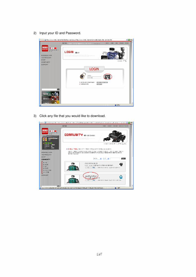
197
2) Input your ID and Password.
3) Click any file that you would like to download.
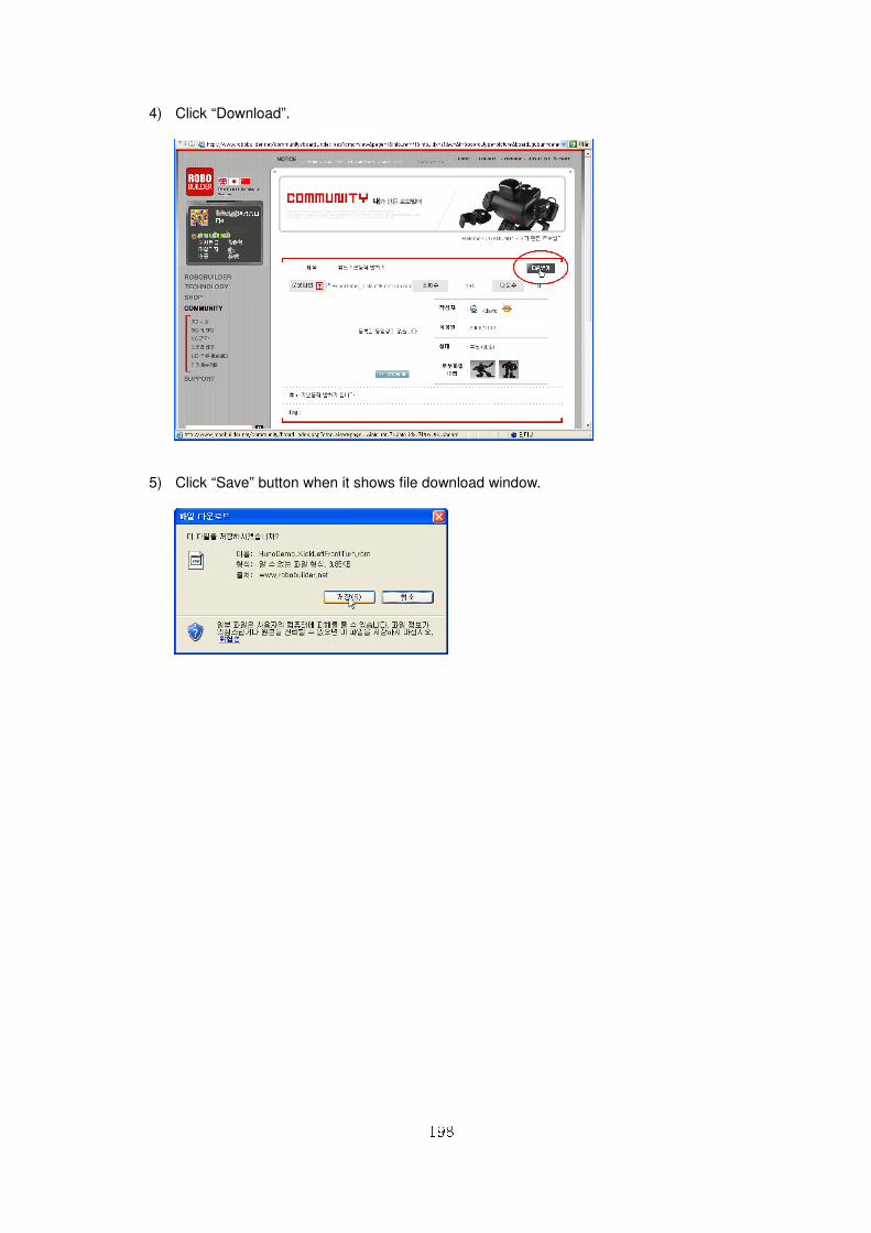
198
4) Click “Download”.
5) Click “Save” button when it shows file download window.
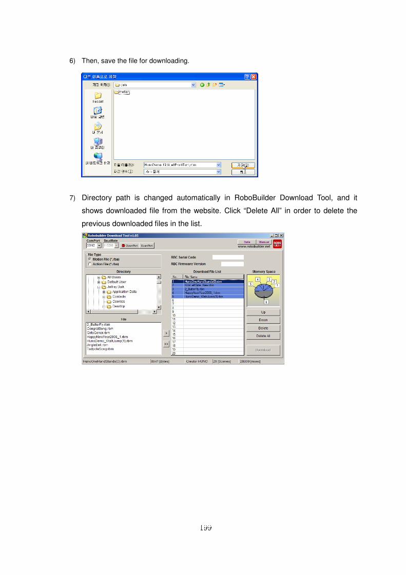
199
6) Then, save the file for downloading.
7) Directory path is changed automatically in RoboBuilder Download Tool, and it
shows downloaded file from the website. Click “Delete All” in order to delete the
previous downloaded files in the list.
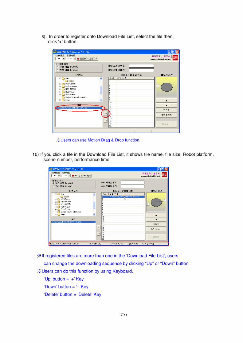
200
8) In order to register onto Download File List, select the file then,
click ‘>’ button.
※ Users can use Motion Drag & Drop function.
10) If you click a file in the Download File List, it shows file name, file size, Robot platform, scene number, performance time.
※ If registered files are more than one in the ‘Download File List’, users
can change the downloading sequence by clicking “Up” or “Down” button. ※ Users can do this function by using Keyboard.
‘Up’ button = ‘+’ Key
‘Down’ button = ‘-‘ Key
‘Delete’ button = ‘Delete’ Key

201
11) Plug the adapter into RoboBuilder, then connect RoboBuilder with PC through PC
download cable. Power on RBC Box.
12) Click ‘ScanPort’ button in order to find available COM Port.
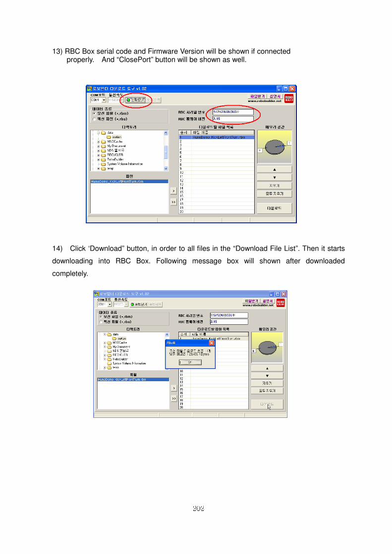
202
13) RBC Box serial code and Firmware Version will be shown if connected properly. And “ClosePort” button will be shown as well.
14) Click ‘Download” button, in order to all files in the “Download File List”. Then it starts
downloading into RBC Box. Following message box will shown after downloaded
completely.
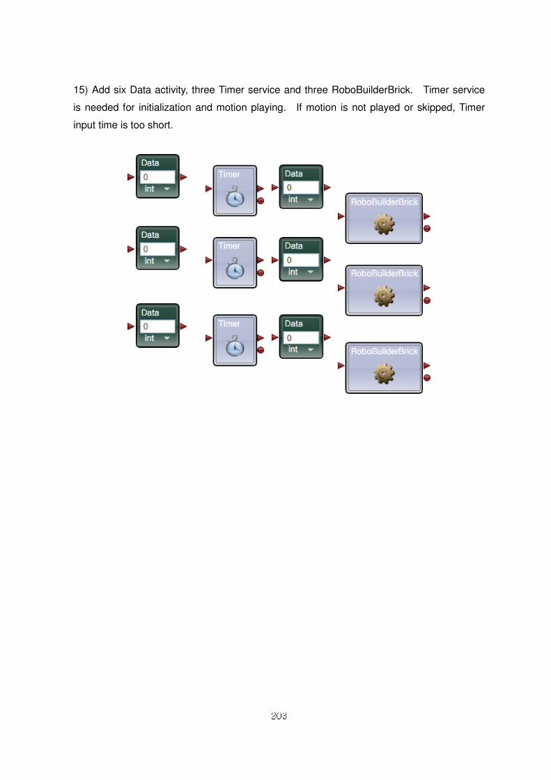
203
15) Add six Data activity, three Timer service and three RoboBuilderBrick. Timer service
is needed for initialization and motion playing. If motion is not played or skipped, Timer
input time is too short.
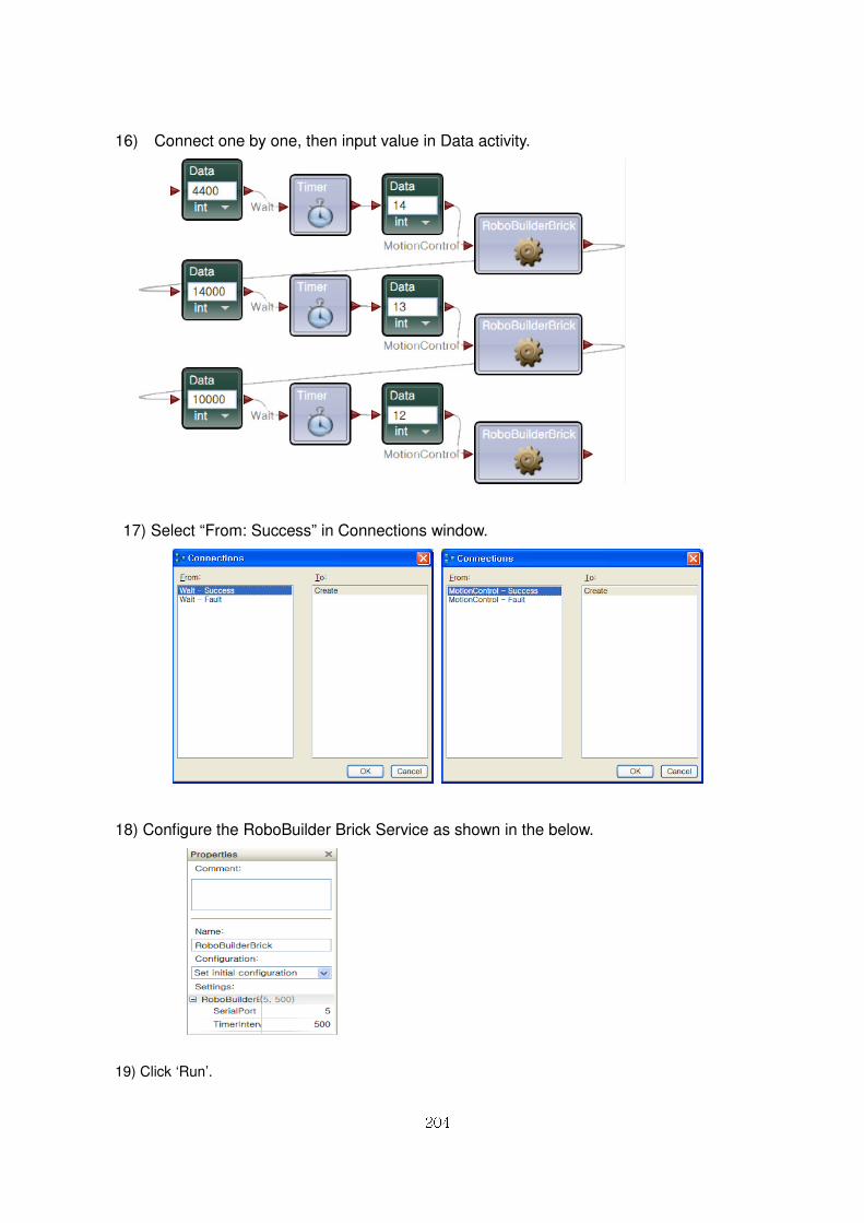
204
16) Connect one by one, then input value in Data activity.
17) Select “From: Success” in Connections window.
18) Configure the RoboBuilder Brick Service as shown in the below.
19) Click ‘Run’.
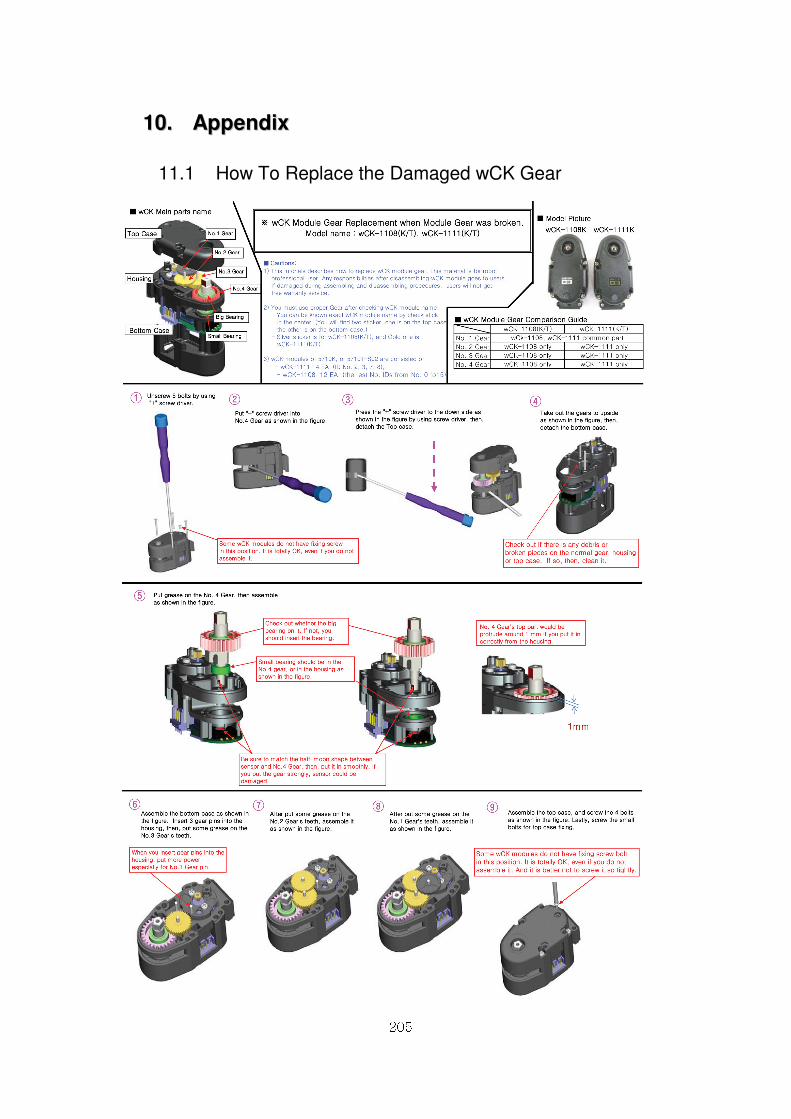
205
1100.. AAppppeennddiixx
11.1 How To Replace the Damaged wCK Gear
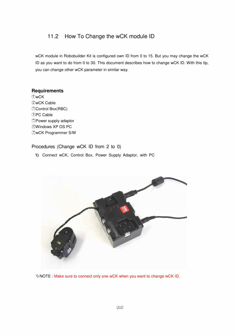
206
11.2 How To Change the wCK module ID
wCK module in Robobuilder Kit is configured own ID from 0 to 15. But you may change the wCK
ID as you want to do from 0 to 30. This document describes how to change wCK ID. With this tip,
you can change other wCK parameter in similar way.
Requirements ① wCK ② wCK Cable ③ Control Box(RBC) ④ PC Cable ⑤ Power supply adaptor ⑥ Windows XP OS PC ⑦ wCK Programmer S/W
Procedures (Change wCK ID from 2 to 0)
1) Connect wCK, Control Box, Power Supply Adaptor, with PC
※ NOTE : Make sure to connect only one wCK when you want to change wCK ID.
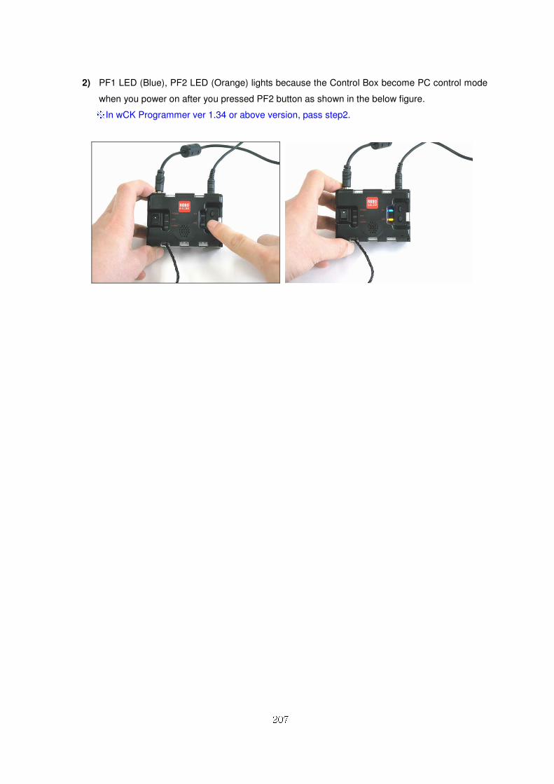
207
2) PF1 LED (Blue), PF2 LED (Orange) lights because the Control Box become PC control mode
when you power on after you pressed PF2 button as shown in the below figure. ※ In wCK Programmer ver 1.34 or above version, pass step2.

ERROR: undefined
OFFENDING COMMAND: f‘~
STACK: