rig : a simple, secure and exible design for password ... · rig : a simple, secure and exible...
TRANSCRIPT

Rig∗ : A simple, secure and flexible design for Password Hashing
Version 2.0
Donghoon Chang, Arpan Jati, Sweta Mishra,Somitra Kumar Sanadhya
Indraprastha Institute of Information Technology, Delhi(IIIT-Delhi), India
{donghoon,arpanj,swetam,somitra}@iiitd.ac.in
September 23, 2014
∗The name of our scheme is inspired from the ancient Hindu religious text Rig-Veda.
i

Contents
1 Introduction 1
2 Cryptographic preliminaries 32.1 Techniques . . . . . . . . . . . . . . . . . . . . . . . . . . . . . . . . . . . . . . . 3
3 Attack platforms: Significant hardwares 3
4 Specification 4
5 Design rationale 7
6 Implementation aspects 96.1 Design of Rig [Blake2b, BlakeCompress, Blake2b] . . . . . . . . . . . . . . . . . . 9
6.1.1 Design of the BlakeCompress function . . . . . . . . . . . . . . . . . . . . 106.2 Design of Rig [BlakeExpand, BlakePerm, Blake2b] . . . . . . . . . . . . . . . . . 10
6.2.1 Design of the BlakeExpand expansion function . . . . . . . . . . . . . . . 106.2.2 Design of BlakePerm function . . . . . . . . . . . . . . . . . . . . . . . . . 11
6.3 Parallelization . . . . . . . . . . . . . . . . . . . . . . . . . . . . . . . . . . . . . . 146.4 GPU resistance . . . . . . . . . . . . . . . . . . . . . . . . . . . . . . . . . . . . . 146.5 ASIC/FPGA resistance . . . . . . . . . . . . . . . . . . . . . . . . . . . . . . . . 14
7 Performance analysis 147.1 Suggested parameters . . . . . . . . . . . . . . . . . . . . . . . . . . . . . . . . . 15
8 Security analysis 158.1 Resistance against low memory attack . . . . . . . . . . . . . . . . . . . . . . . . 178.2 Resistance against collision attack . . . . . . . . . . . . . . . . . . . . . . . . . . 20
8.2.1 Instantiation of Rig [H1, H2, H3] for reference implementations . . . . . . 228.3 Resistance against length extension attack . . . . . . . . . . . . . . . . . . . . . . 248.4 Resistance against cache-timing attack . . . . . . . . . . . . . . . . . . . . . . . . 248.5 Resistance against denial-of-service attack . . . . . . . . . . . . . . . . . . . . . . 25
9 Intellectual property statement 25
10 Appendix 2610.1 ChangeLog . . . . . . . . . . . . . . . . . . . . . . . . . . . . . . . . . . . . . . . 26
List of Tables
1 Performance of RIG [Blake2b, BlakeCompress, Blake2b] . . . . . . . . . . . . . . 162 Performance of RIG [BlakeExpand, BlakePerm, Blake2b] . . . . . . . . . . . . . . 16
List of Figures
1 Graphical representation of the proposed construction. . . . . . . . . . . . . . . . 52 Function H2 implemented as function BlakeCompress[x] = y, where input length
of x= 1024 bits and output length of y = 512 bits. RF1 is the first round ofBlake2b compression function. Input size of RF1 = 1024 bits. . . . . . . . . . . 10
3 Blake2b compression function . . . . . . . . . . . . . . . . . . . . . . . . . . . . 114 Function BlakeExpand . . . . . . . . . . . . . . . . . . . . . . . . . . . . . . . . 12
ii

5 Function H2 implemented as function BlakePerm. . . . . . . . . . . . . . . . . . 136 Performance of Rig (at different value of n) and Scrypt. . . . . . . . . . . . . . . 157 Graphical representation of the calculation for the low memory complexity of ‘Rig’. 198 Rig[H1, H2, H3](x,mc, n, s), where H2 signifies repetitive use of H2. . . . . . . . 219 Five cases showing collisions for Rig [H1, H2, H3]. . . . . . . . . . . . . . . . . . . 2210 Setup phase uses m inputs generated from α. . . . . . . . . . . . . . . . . . . . . 2311 H2 implemented with RF1 at iteration i = n. . . . . . . . . . . . . . . . . . . . . 24
iii
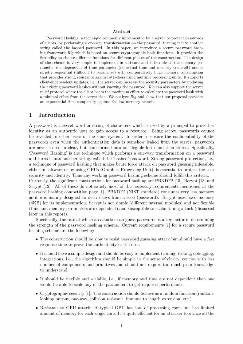
Abstract
Password Hashing, a technique commonly implemented by a server to protect passwordsof clients, by performing a one-way transformation on the password, turning it into anotherstring called the hashed password. In this paper, we introduce a secure password hash-ing framework Rig which is based on secure cryptographic hash functions. It provides theflexibility to choose different functions for different phases of the construction. The designof the scheme is very simple to implement in software and is flexible as the memory pa-rameter is independent of time parameter (no actual time and memory trade-off) and isstrictly sequential (difficult to parallelize) with comparatively huge memory consumptionthat provides strong resistance against attackers using multiple processing units. It supportsclient-independent updates, i.e., the server can increase the security parameters by updatingthe existing password hashes without knowing the password. Rig can also support the serverrelief protocol where the client bears the maximum effort to calculate the password hash witha minimal effort from the server side. We analyze Rig and show that our proposal providesan exponential time complexity against the low-memory attack.
1 Introduction
A password is a secret word or string of characters which is used by a principal to prove heridentity as an authentic user to gain access to a resource. Being secret, passwords cannotbe revealed to other users of the same system. In order to ensure the confidentiality of thepasswords even when the authentication data is somehow leaked from the server, passwordsare never stored in clear, but transformed into an illegible form and then stored. Specifically,‘Password Hashing’ is the technique which performs a one-way transformation on a passwordand turns it into another string, called the ‘hashed’ password. Strong password protection, i.e.,a technique of password hashing that makes brute force attack on password guessing infeasible,either in software or by using GPUs (Graphics Processing Unit), is essential to protect the usersecurity and identity. Thus any working password hashing scheme should fulfill this criteria.Currently, the significant constructions for password hashing are PBKDF2 [15], Bcrypt [13] andScrypt [12]. All of these do not satisfy most of the necessary requirements mentioned at thepassword hashing competition page [1]. PBKDF2 (NIST standard) consumes very less memoryas it was mainly designed to derive keys from a seed (password). Bcrypt uses fixed memory(4KB) for its implementation. Scrypt is not simple (different internal modules) and not flexible(time and memory parameters are dependent) and susceptible to cache timing attack (discussedlater in this report).
Specifically, the rate at which an attacker can guess passwords is a key factor in determiningthe strength of the password hashing scheme. Current requirements [1] for a secure passwordhashing scheme are the following:
• The construction should be slow to resist password guessing attack but should have a fastresponse time to prove the authenticity of the user.
• It should have a simple design and should be easy to implement (coding, testing, debugging,integration), i.e., the algorithm should be simple in the sense of clarity, concise with lessnumber of components and primitives and should not require too much prior knowledgeto understand.
• It should be flexible and scalable, i.e., if memory and time are not dependent then onewould be able to scale any of the parameters to get required performance.
• Cryptographic security [1]: The construction should behave as a random function (random-looking output, one-way, collision resistant, immune to length extension, etc.).
• Resistant to GPU attack: A typical GPU has lots of processing cores but has limitedamount of memory for each single core. It is quite efficient for an attacker to utilize all the
1
available processing cores with limited memory to run brute-force attack over the passwordchoices. Use of comparatively huge memory per password hash by the password hashingconstruction can restrict the use of GPU. Therefore, the design should have large memoryconsumption to force comparatively slow and costly hardware implementation that canresist the GPU attack.
• Leakage Resilience: The construction should protect against information extraction fromphysical implementation, i.e., the scheme should not leak information about the passworddue to cache timing or memory leakage, while supporting any length of password.
• The construction should have the ability to transform an existing hash to a different costsetting without knowledge of the password.
• It is good if the construction provides server relief technique where the client performsmost of the computations for password hashing and the server puts minimal effort withminimal use of resources, to reduce the load of the server. This property needs a secureprotocol to maintain the security of the hash computation.
The most challenging threat faced by any password hashing scheme is the existence of cheap,massively parallel hardware such as Graphics Processing Units (GPUs), Application-Specific In-tegrated Circuits (ASICs) and Field-Programmable Gate Arrays (FPGAs). Using such efficienthardware, an adversary with multiple computing units can easily try multiple different passwordsin parallel. To prevent such attempts we need to slow down password hash computation andensure that there is little parallelism in the design. One way to achieve this is to use a ‘Sequentialmemory-hard’ algorithm, a term first introduced with the design of ‘Scrypt’ [12], a passwordhashing scheme. The main design principle of Scrypt is that it asymptotically uses almost asmany memory locations as it uses operations to make the password-hash computation processslow. Memory is relatively expensive, so, a typical GPU or other cheap massively-parallel hard-ware with lots of cores can only have a limited amount of memory for each single core. Hence anattacker with access to such hardware will still not be able to utilize all the available processingcores due to the lack of sufficient memory and will be forced to have an (almost) sequentialimplementation of the password hashing scheme.
In this document we propose ‘Rig’, a password hashing scheme which aims to address theabove mentioned requirements. ‘Rig’ is based on cryptographic (secure) hash functions and isvery simple to implement in software. It is flexible as the memory parameter is independentof time parameter (no actual time and memory trade-off) and is strictly sequential (difficultto parallelize) with comparatively huge memory consumption that provides strong resistanceagainst attackers using multiple processing units. It supports client-independent password hashup-gradation without the need of the actual password. This feature helps the server to increasethe security parameters to calculate the password hash to reduce the constant threats of tech-nological improvements, specifically in the field of hardware. ‘Rig’ provides protection againstthe extraction of information from cache-timing attack and prevents denial-of-service attack ifimplemented to provide server-relief technique. We analyze ‘Rig’ and show that our proposalprovides an exponential time complexity against memory-free attack. It gives the flexibility tochoose different functions for different phases of the construction and we denote the generalconstruction of ‘Rig’ as Rig [H1, H2, H3]. In this report we provide two variants of Rig [H1,H2, H3]. A strictly sequential variant, Rig [Blake2b, BlakeCompress, Blake2b] and the othervariant, Rig [BlakeExpand, BlakePerm, Blake2b] which improves the performance by performingmemory operations in larger chunks.
The rest of the document is organized as follows. In section 2 we present the techniquesnecessary for understanding the specification. This is followed by the introduction of significanthardwares used as attack platform in section 3. The specification and design rationale of thescheme is presented in sections 4 and 5 respectively. Subsequently, the implementation aspects
2

and performance analysis are presented in sections 6 and 7. Finally, in section 8, we provide thesecurity analysis of the scheme. At the end we conclude the report with an intellectual propertystatement, the bibliography, with changelog in appendix and acknowledgements.
2 Cryptographic preliminaries
The simple techniques explained below are the basis of our construction ‘Rig’:
2.1 Techniques
• Binary 64-bit mapping: It is a 64-bit binary representation of the decimal value. Thebinary number
an−12n−1 + an−22n−2 + · · ·+ a0
is denoted as an−1an−2 · · · a0 where ai ∈ {0, 1} and n is the number of digits to the left ofthe binary (radix) point. In our construction we use n = 64 and we denote binary64(x)for 64-bit binary representation of the value x.
• Bit reversal permutation [8, 11] (br) : It is implemented to permute the indices of anarray of n = 2k elements where k ∈ N. We explain the steps of the permutation throughAlgorithm 1 below.The example of a bit reversal permutation applied on an array of m = 23 elements wherek = 3 and indices are 0, 1, · · · , 7 is given below.
br[000, 001, 010, 011, 100, 101, 110, 111] = [000, 100, 010, 110, 001, 101, 011, 111]
= br[0], br[1], br[2], br[3], · · · , br[7].
Algorithm 1: Bit reversal permutation (br)Input: Indices of an array A of n = 2k elements where k ∈ N and
indices are: 0, 1, 2, · · · , n− 1.Output: Permuted indices of array A as: br[0], br[1], br[2], · · · , br[n− 1]
1. for i = 0 to n− 1
2. (i)bink= ik−1ik−2 · · · i1i0 =
∑k−1j=0 2jij
3. . (i)bink= k-bit binary representation of value i
4. br[i] =∑k−1
j=0 2jik−1−j5. return br[0], br[1], br[2], · · · , br[n− 1]
3 Attack platforms: Significant hardwares
According to Moore’s Law [14], the number of transistors on integrated circuits doubles approx-imately every two years. This has indeed been the case over the history of computing hardware.Following this law, hardware is becoming more and more powerful with time. This happens tobe the most prominent threat for existing password hashing schemes. Consequently, there isa need to raise the cost of brute force attack by controlling the performance of the massivelyparallel hardware available.
An important electronic circuit, Graphics Processing Unit (GPU), specifically designedto rapidly manipulate and alter memory to accelerate the creation of the memory-intensive workof texture mapping and rendering polygons. Modern GPUs are very efficient and their highlyparallel structure makes them more effective than general-purpose CPUs for algorithms whereprocessing of large blocks of data is done in parallel. An Application-Specific IntegratedCircuit (ASIC), is an integrated circuit (IC) which can be customized with memory chips to
3

implement a dedicated design. An ASIC can not be altered after final design hence the designersneed to be certain of their design when it is implemented in ASIC. On the other hand, FieldProgrammable Gate Arrays (FPGAs) are programmable integrated circuits and consist ofan array of logic elements together with an interconnected network and memory chips, providinghigh-performance. A designer can test her design on an FPGA before implementing it on anASIC.
Both ASIC and FPGAs can be configured to perform password hashing with highly optimizedperformance. The cost of implementation on FPGA is cheaper than ASICs if the number ofunits of the hardware required is small. Therefore, one can easily use parallel FPGAs to increasethe rate of password guessing. RIVYERA FPGA cluster is an example of a very powerful andcost optimized hardware. It can hash 3,56,352 passwords per second by using PBKDF2 (NISTstandard, Password Based Key Derivation Function 2) with SHA-512 and 512-bit derived keylength [7]. This high performance is possible on the FPGA because PBKDF2 does not consumehigh memory for password hashing. Comparing FPGAs with GPUs (Graphics processing units),the authors of [7] provide results of the same implementation on 4 Tesla C2070 GPUs as 1,05,351passwords per second. ASIC is better than FPGA purely on performance in terms of numberof hashes per second. However, FPGA is preferable when cost is considered with the speed ofhashing. Following Moore’s law, the speed of hardware is likely to increase by almost a factor oftwo in less than two years. However, as processor speeds continue to outpace memory speeds [9],the gap between processor and memory performance increases by about 50 % per year [5]. Thus,there is a need to minimize the effects of such high performance hardware. Hence, we need apassword hashing algorithm which consumes comparatively large memory to prevent parallelimplementation.
4 Specification
Our construction is described in Figure 1. Following is the step-by-step description of Algo-rithm 2 which explains our construction ‘Rig’.
1. First we need to fix the following parameters:
• pwd = The user password of any length.
• s = The salt value of any length.
• n = The number of iterations required to perform iterative transformation phase.
• mc = The memory count from which the memory-cost is defined as: m = 2mc , i.e., mdenotes the number of items to be stored in the memory. The value of m is updatedas: mi+1 = 2×mi at each round.
• r = The number of rounds for the setup phase followed by iterative transformationphase and output generation phase.
• l = The output length of the password hash.
• t = The number of bits retained from the hash output after truncation. Used with afunction trunct(x) = x� (|x| − t), where x is the hash output.
• Initialization phase: We map each of the above parameters, namely the values,i.e., password length pwdl, salt length sl, iteration count n and the output length lto 64-bit binary strings using binary64 mapping. We create x as the concatenation(‖) of the these parameters and compute a value α as:
x = pwd ‖ binary64(pwdl) ‖ s ‖ binary64(sl) ‖ binary64(n) ‖ binary64(l);
H1(x) = α.
where H1 is the underlying hash function. We use α for further computations in thesetup phase.
4

H2 H2
H2H2
H3 h∗
1 2
(m+ 1) (m+ 2)
k[1]
H2H2
(2m+ 1) (2m+ 2)
H2H2 H2
(nm+ 1) (nm+ 2) (n+ 1)m
k[0] k[m-1]
((n+ 1)m+ 1)
∗Note: :Shows first t−bit truncation and value depends on implementation.k[br[i]] : is the ith index of array k obtained from bit reversal permutation
k[2]
α
t t tt
h0
t t t t
tt t t
t t t t
t
i=1
i=2
i= n
s||m
a[0] a[1] a[m-1]
a[0] a[1]
a[0]
a[0]
a[1]
a[1] a[m-1]
H2
H2a[m-1]
H2a[m-1]
m
2m
3m
H2H2
H2
H2
H2
Initialization phase:
Iterative Transformationphase:
SetupPhase:
Output generation phase:output of each round
α α
k[br[0]] k[br[1]] k[br[2]]k[br[m− 1]]
k[br[m− 1]]
k[br[m− 1]]
k[br[2]]
k[br[2]]
k[br[0]]
k[br[0]]
k[br[1]]
k[br[1]]
H2
H1xαH1
for round= 1, m = 2mc
k[0] k[1]
k[1]k[0]
k[2]
k[2]
k[m-1]
k[m-1]
x = pwd ‖ binary64(pwdl) ‖ s ‖ binary64(sl) ‖ binary64(n) ‖ binary64(l)
Figure 1: Graphical representation of the proposed construction.
• Setup phase: We initialize h0 with the value of π after the decimal point. We takeas many digits of π as desired to ensure that |h0| = |α|. The values h0 and α are usedto initialize two arrays k and a and further m− 1 values of the arrays are iterativelycalculated as shown in Figure 1. First t-bit output of each call of hash function H2
are stored in the array k.
The large number of calls to the underlying hash function are expected to havedifferent inputs by the use of different counter values. Note that H2 is the underlyinghash function.
5

Rig: A password hashing schemeAlgorithm 2: Rig [H1, H2, H3] Construction
Input: Password (pwd), Password length (pwdl), Salt (s), Salt length (sl), No. of iterations (n),Memory count (mc), No. of bits to be retained from hash output of the setup phase (t),Output length (l), No. of rounds (r).
Output: l-bit hash value hr∗ obtained after r rounds
1. . Initialization phase: generates α from password2. Initialize: a random salt (s) of atleast 16-bytes, number of iterations (n),
value of memory count mc where m = 2mc , value t3. x = pwd ‖ binary64(pwdl) ‖ s ‖ binary64(sl) ‖ binary64(n) ‖ binary64(l) . concatenation: ‖4. α = H1(x) . H1 : underlying hash function5. for round 1 to r6. . Initialization of Setup phase: Creates two arrays k and a
where |k| = |a| = m where m = 2(round−1) × 2mc
7. h0 = initialized with the value of π after decimal, and |h0| = |α|.8. a[0] = α⊕ h0, k[0] = trunct(h0)9. for i = 1 to m
10. hi = H2(i ‖ a[i− 1] ‖ k[i− 1]) . H2 : underlying hash function11. if i 6= m12. a[i] = α⊕ hi13. k[i] = trunct(hi) . retains the first t−bits of the hash output14. . Initialization of Iterative Transformation phase15. for i = 1 to n16. for j = 1 to m17. a[j − 1] = a[j − 1]⊕ h{im+j−1}18. br[j − 1] = index value of array k obtained using
bit reversal permutation19. . initialize a temporary array |ktemp| = |k|20. ktemp[j − 1] = k[br[j − 1]]⊕ trunct(him+j−1)
21. him+j = H2((im+ j) ‖ a[j − 1] ‖ ktemp[j − 1])
22. k = ktemp23. . Output generation phase24. hround
∗ = (H3((n+ 1)m+ 1) ‖ h(n+1)m ‖ s ‖ binary64(m))25. if round < r26. α = hround
∗
2. Iterative transformation phase: This phase is designed to make repeated use of thestored array values and to update them. We modify each element of the arrays a and k,n-times where n is the number of iterations. Array a is accessed sequentially whereas arrayk is accessed using bit reversal permutation as explained in Algorithm 1. We denote theindex of array k obtained by applying bit-reversal permutation as: br[j], 0 ≤ j ≤ m− 1.
3. Output generation phase: After execution of the setup phase and iterative transfor-mation phase sequentially, we apply one more hash function, denoted by H3, to get theoutput of each round. This output is used to reinitialize α for the computations of nextround. In the last round, this output of H3 becomes the password hash.Note: The output is an l-bit value. The algorithm stores the output as the hashed pass-word. Our construction allows for storing a truncated portion of the hash output as well.If this is desired we can take one of the following two approaches.
(a) The user may run the complete algorithm as described above and truncate the finaloutput after r rounds to the desired length. This approach does not support client-independent update.
(b) To support client-independent updates the user can choose a length for truncationwhich is sufficient to claim brute-force security. Then append some constant value,
6

we suggest the hexadecimal value of π after first 512-bits of decimal point. Take asmany digits as desired to make the output length of each round equal to the length ofα of the setup phase. This way one can reduce the storage requirement for passwordhashes at the server.
5 Design rationale
Existing password hashing schemes are not simple and do not fulfill the necessary requirementsas discussed in section 1. We have tried to design a solution which overcomes the known disad-vantages of existing schemes (PBKDF2 [15], Bcrypt [13] and Scrypt [12]). The primary concernsagainst existing proposals are their complex design and their inefficiency to prevent hardwarethreats. We have tried to strengthen our design by considering the necessary requirements asmentioned in section 1.
1. Initialization phase: We have used concatenation of password, salt, 64-bit value of pwdl,sl, n and l as input to increase the size of input. This resists brute force dictionary attack.
2. Setup phase: In this phase we initialize h0 with π, as we want to have a random sequenceand π is not known to have any pattern in the sequence of digits after the decimal point.We generate the values that are required to be stored and repeatedly accessed throughoutthe remaining phases. This ensures that a large memory is requirement for the passwordhashing scheme which neutralizes the threat of using recent technological trends, such asGPUs, ASICs etc. We use different counter values for each hash calculation to make allhash inputs different. This reduces collisions and hence makes the output different.
For array k there is a flexibility to vary the bit storage by taking first t-bits of the hashoutput where t is taken to be close to the hash-length but not equal to the hash-length.This fulfills the demand of huge memory while at the same time ensures sequential hashcalculation and forces an attacker to compute the hash at run-time thus slowing him down.Further, it also allows to extend the scope of implementation in that a low memory devicemay keep very few bits of the hash values stored but may increase the number of iterations.This ensures that ‘Rig’ can be implemented in resource constrained devices.
3. Iterative transformation phase: To make the storage requirement compulsory, thisphase progresses sequentially, accessing and updating all stored values at each iteration.Here again, we use different counters for hash input for the same reason as mentionedabove. In this phase the memory access pattern is made password independent to reducethe chance of cache timing attack which we have explained later in this section.
4. Output generation phase: This is the last phase of each round. We reuse the salt valueas input to make the collision attack difficult. Apart from that the output of each roundcan be truncated to a desired length. This is optionally mentioned to handle the situationswhen it is required to reduce the server storage per password.
The other important criteria taken into account in the design of the scheme are the following:
5. Simplicity and Flexibility: Symmetry (as setup phase and iterative transformationphase follows similar structure) in the design of ‘Rig’ enhances the overall clarity ofthe scheme. An earlier password hashing scheme Scrypt [12] uses PBKDF2 (internallycalls HMAC-SHA256) and ROMix (internally calls BlockMix and uses Salsa20/8). UnlikeScrypt, ‘Rig’ uses only a single primitive (a cryptographically secure hash function). Thismakes our scheme easier to understand and easy to implement (coding, testing, debuggingand integration).
7
The design Scrypt [12] is not flexible enough as its time complexity: 4Nr and memorycomplexity: Nr depend on each other, i.e., if we reduce the value of N (for RoMix function)or r (for BlockMix), it automatically reduces the memory consumption. This is not thecase in our construction. In our design the time complexity is O(n+1)mr and the memorycomplexity is O(m). Therefore, we have the flexibility that if we decrease the value of mwe can increase the number of iterations n and vice-versa. This flexibility in design choiceallows a user to scale any of these parameters to get the required performance.
Apart from these our scheme also provides the flexibility to choose different functions fordifferent phases of the construction. Therefore it is possible to design different variants ofRig [H1, H2, H3] with different implementations of the functions H1 or H2 or H3.
6. Random output: Our scheme calls a hash function repeatedly. We use different coun-ters for each of these hash calls to ensure that no input to the hash function is repeated.The security of ‘Rig’ relies on the prevention of preimage and collision attacks against theunderlying hash function. Use of any state-of-the-art hash function (e.g. any finalist ofSHA-3 competition) ensures the security of our scheme. We use Blake2b [3] in demonstrat-ing the performance of our scheme later in this paper, although any other hash functioncould easily be used instead.
With the property of different input, different output and same input, same output, ourscheme mimics the Random Oracle Model. This provides theoretical justification of thesecurity of ‘Rig’.
7. Client-independent update: Our design supports the idea of client independent updateas explained in [8]. The idea explains how server can increase the security parameter ofa password hash without knowing the password of the client. For our construction this ispossible if we fix the value of n (number of iterations) and increase the number of roundsr. Each round of the algorithm doubles the memory consumption m from the previousround and hence increases the security parameter. This is possible because the output ofeach round can be treated as the value α at the next round and then can easily followthe Algorithm 2 to produce the output of the next round. The idea of client independentupdate of the security parameter m is fulfilled by the following way. The value of m isupdated at each next round i + 1 (say) from its previous round i as: mi+1 = 2 × mi.Taking m1 = 2mc this gives mi+1 = 2mc+i.
The overall procedure is: output of each round is the input to the next. Each roundgives full hash maintaining all requirements of a good password hashing technique. Byincreasing the number of rounds, the scheme increases the required memory and time,hence increases the security parameter without the interference of the client.
8. Resistance against cache-timing attack: In our construction we use bit-reversal per-mutation to access the memory which is stored in an array k. This permutation is in-dependent of the password used. If a password dependent permutation is used and ifthe array can be stored in the cache while accessing the values, an attacker can tracethe access pattern observing the time difference in each access of the array index. Thishelps the adversary to filter the passwords that follows similar memory access pattern andto make a list of feasible passwords. Therefore, a password hashing scheme should havepassword-independent memory access patterns and to follow this requirement we use bitreversal permutation as in [8].
9. Server-relief hashing: Current requirement of a password hashing technique is that itshould be slow and should demand comparatively large memory to be implemented. Butthis requirement may put extra load on server. Therefore we need a protocol to divide theload between the client and the server. This can be achieved by using a challenge-response
8
protocol, such as the ones commonly used in RFID authentication protocols. We use anidea similar to [8] for server relief. This is explained below.First the authentication server provides the salt to the client. The client performs theinitialization phase, setup phase and iterative transformation phase (see Algorithm 2),and sends the end result to the server. The server calculates the output generation phaseand produces the final hash. This way the load of the server can be easily reduced.Note: In this case, an attacker acting as a client, can repeatedly send some random datawithout following the proposed algorithm to the server. The attacker can easily get theaccess with a correct guess. But, the complexity of an attacker winning using this strategy(i.e. using random guesses) will be equivalent to the brute-force complexity, i.e., 2n wheren is the output length of the underlying hash function. Therefore this is not a feasibleattack strategy.
6 Implementation aspects
This proposed construction for password hashing can be implemented efficiently on a wide rangeof processors. However, the same implementation will require huge number of computations ifdedicated hardware such as ASIC or FPGA is used with limited memory.
Our design allows the flexibility to utilize less storage with increased number of calculations ifwe truncate few bits of the intermediate hash computation and increase the number of iterationsn. This way, ‘Rig’ can be efficient on low memory devices.
We designed Rig to have a highly flexible structure. By changing the functions H1, H2 andH3 (see Figure 1) we can completely change the overall design properties. From side channelresistance to GPU or ASIC/FPGA resistance, any property can be achieved by the properselection of the above primitives. Therefore there can be multiple variants aimed at differentimplementations or scenarios. As mentioned before, we describe the general construction of‘Rig’ as Rig [H1,H2,H3], where we can design/choose the functions H1, H2, H3 for implementingdifferent variants of ‘Rig’.
In this report, we have included two variants of ‘Rig’. The detailed description with designand implementations are described below.
1. Rig [Blake2b, BlakeCompress, Blake2b] This variant is strictly sequential. FullBlake2b is used for H1 and H3 while the first round of the compression function of Blake2bis used for H2 (and we call it BlakeCompress). We have removed the constants in the‘G’ function of Blake2b as suggested by the Blake authors in [3] to improve the overallperformance.
This version does a large number of random reads and writes and as a result it is strictlybounded by memory latency.
2. Rig [BlakeExpand, BlakePerm, Blake2b] This variant is designed to improve the per-formance by performing memory operations in larger chunks. The functions H1 and H2 areparallelized internally and the idea of handling larger chunk size improves the performancesignificantly without changing the overall sequential nature and memory-hardness of ‘Rig’.It also makes this variant of ‘Rig’ much more difficult to execute efficiently in GPUs andFPGA/ASIC (explained in sections 6.4 and 6.5). We implemented the functions H1 as‘BlakeExpand’ and H2 as ‘BlakePerm’. These functions are explained later. The functionH3 uses full Blake2b.
6.1 Design of Rig [Blake2b, BlakeCompress, Blake2b]
This strictly sequential variant follows the general construction of ‘Rig’ as explained in section 4.The functions H1 and H2 implements Blake2b (full hash). The function H2 is implemented using
9

first round of Blake2b compression function as described in the following section.
6.1.1 Design of the BlakeCompress function
In Figure 2 we graphically show the implementation of H2 as BlakeCompress. H2 takes 1024bits input and initializes the initial state of Blake2b with this input. Then the eight G-functionsas defined in Blake2b are applied with an all zero input message of length 1024 bits. RFi
denotes the ith call to these eight G-functions. As we use the first round only, we show theround as RF1 in Figure 2. The modified state after RF1 is then split in two equal halves andxor’ed together to produce 512-bits of output. This choice of implementation is different fromthe actual Blake2b in many ways. The actual Blake2b construction, shown in Figure 3, hasan initialization phase which initializes the starting state. A permutation of the message mi issupplied as the input to each RFi for round i = 1 to 12. After 12 rounds, the finalization phaseperforms feedforward xor’ing with output of RF12. This preserves the onewayness of the Blake2bfunction. This feedforward xor’ing is omitted in our BlakeCompress implementation. This choiceof implementation reduces the time of hash computation and improves the performance. Theoverall security is not compromised by this implementation (see section 8.2.1).
RF1
512 bits
512 bits
message (0)
BlakeCompress
x 512 bits1024 bits
y
Figure 2: Function H2 implemented as function BlakeCompress[x] = y, where input length ofx= 1024 bits and output length of y = 512 bits. RF1 is the first round of Blake2b compressionfunction. Input size of RF1 = 1024 bits.
6.2 Design of Rig [BlakeExpand, BlakePerm, Blake2b]
The optimized variant of ‘Rig’ uses an expansion function BlakeExpand to expand the stateand a compression function, BlakePerm to compress the state. Full Blake2b is used to hashthe output state after the iterative-transformation phase to obtain the final hash. The designaspects are described below.
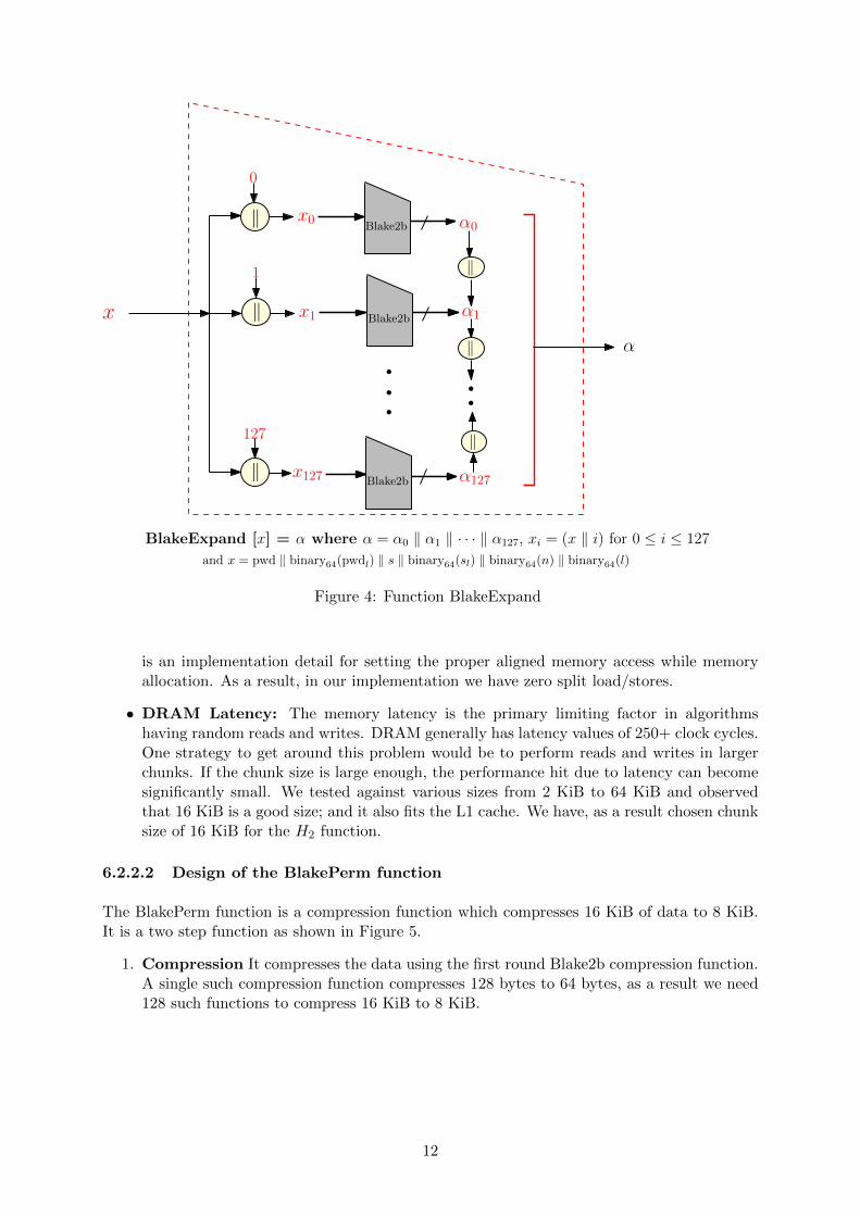
6.2.1 Design of the BlakeExpand expansion function
The BlakeExpand function is a very simple function which expands the input x to a fixed sizeof 8KiB as shown in Figure 4. Technically any input length is allowed, but, in any practicalscenario the password and salt length do not exceed 8 KiB1. Recall that our design uses three
11 kibibyte (KiB) is 1024 bytes
10
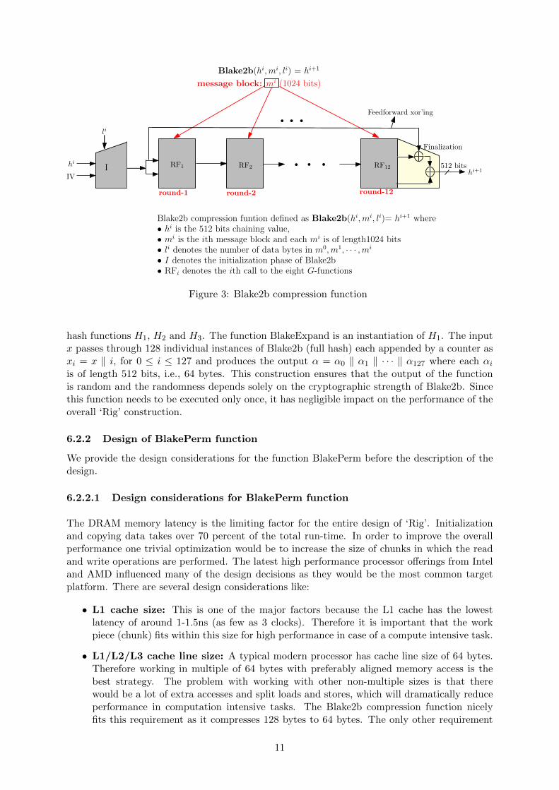
RF1
round-1 round-2 round-12
Finalization
Feedforward xor’ing
li
IV
RF2 RF12hi
message block: mi (1024 bits)
Blake2b(hi,mi, li) = hi+1
512 bitshi+1I
Blake2b compression funtion defined as Blake2b(hi,mi, li)= hi+1 where• hi is the 512 bits chaining value,• mi is the ith message block and each mi is of length1024 bits• li denotes the number of data bytes in m0,m1, · · · ,mi
• I denotes the initialization phase of Blake2b• RFi denotes the ith call to the eight G-functions
Figure 3: Blake2b compression function
hash functions H1, H2 and H3. The function BlakeExpand is an instantiation of H1. The inputx passes through 128 individual instances of Blake2b (full hash) each appended by a counter asxi = x ‖ i, for 0 ≤ i ≤ 127 and produces the output α = α0 ‖ α1 ‖ · · · ‖ α127 where each αi
is of length 512 bits, i.e., 64 bytes. This construction ensures that the output of the functionis random and the randomness depends solely on the cryptographic strength of Blake2b. Sincethis function needs to be executed only once, it has negligible impact on the performance of theoverall ‘Rig’ construction.
6.2.2 Design of BlakePerm function
We provide the design considerations for the function BlakePerm before the description of thedesign.
6.2.2.1 Design considerations for BlakePerm function
The DRAM memory latency is the limiting factor for the entire design of ‘Rig’. Initializationand copying data takes over 70 percent of the total run-time. In order to improve the overallperformance one trivial optimization would be to increase the size of chunks in which the readand write operations are performed. The latest high performance processor offerings from Inteland AMD influenced many of the design decisions as they would be the most common targetplatform. There are several design considerations like:
• L1 cache size: This is one of the major factors because the L1 cache has the lowestlatency of around 1-1.5ns (as few as 3 clocks). Therefore it is important that the workpiece (chunk) fits within this size for high performance in case of a compute intensive task.
• L1/L2/L3 cache line size: A typical modern processor has cache line size of 64 bytes.Therefore working in multiple of 64 bytes with preferably aligned memory access is thebest strategy. The problem with working with other non-multiple sizes is that therewould be a lot of extra accesses and split loads and stores, which will dramatically reduceperformance in computation intensive tasks. The Blake2b compression function nicelyfits this requirement as it compresses 128 bytes to 64 bytes. The only other requirement
11
α0
α1
x0Blake2b
Blake2b
Blake2b
‖
‖
‖
x1x
0
1
127
‖
‖
‖
α
α127x127
BlakeExpand [x] = α where α = α0 ‖ α1 ‖ · · · ‖ α127, xi = (x ‖ i) for 0 ≤ i ≤ 127
and x = pwd ‖ binary64(pwdl) ‖ s ‖ binary64(sl) ‖ binary64(n) ‖ binary64(l)
Figure 4: Function BlakeExpand
is an implementation detail for setting the proper aligned memory access while memoryallocation. As a result, in our implementation we have zero split load/stores.
• DRAM Latency: The memory latency is the primary limiting factor in algorithmshaving random reads and writes. DRAM generally has latency values of 250+ clock cycles.One strategy to get around this problem would be to perform reads and writes in largerchunks. If the chunk size is large enough, the performance hit due to latency can becomesignificantly small. We tested against various sizes from 2 KiB to 64 KiB and observedthat 16 KiB is a good size; and it also fits the L1 cache. We have, as a result chosen chunksize of 16 KiB for the H2 function.
6.2.2.2 Design of the BlakePerm function
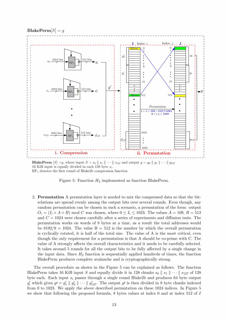
The BlakePerm function is a compression function which compresses 16 KiB of data to 8 KiB.It is a two step function as shown in Figure 5.
1. Compression It compresses the data using the first round Blake2b compression function.A single such compression function compresses 128 bytes to 64 bytes, as a result we need128 such functions to compress 16 KiB to 8 KiB.
12
i
g′1
g′127
g′0
i. Compression ii. Permutation
g1
g127
g
Permutation
BlakePerm [S] =g, where input S = s0 ‖ s1 ‖ · · · ‖ s127 and output g = g0 ‖ g1 ‖ · · · ‖ g12716 KiB input is equally divided in each 128 byte si.RF1 denotes the first round of Blake2b compression function
g′0
g′1
01
15
512
I J
78
Index- i
g′127
g0
1023
1016
01
15
512
78
8Bytes
Index- j
j = (i× 109+ 512)%10240 ≤ i, j ≤ 1023
8Bytes
g′
512 bitss0
1024 bits
0
512 bitss1
1024 bits
0
512 bits1024 bits
0
s127
RF1
RF1
RF1
BlakePerm[S] = g
Figure 5: Function H2 implemented as function BlakePerm.
2. Permutation A permutation layer is needed to mix the compressed data so that the bit-relations are spread evenly among the output bits over several rounds. Even though, anyrandom permutation can be chosen in such a scenario, a permutation of the form: outputOi = (Ii×A+B) mod C was chosen, where 0 ≤ Ii ≤ 1023. The values A = 109, B = 512and C = 1024 were chosen carefully after a series of experiments and diffusion tests. Thepermutation works on words of 8 bytes at a time, as a result the total addresses wouldbe 8192/8 = 1024. The value B = 512 is the number by which the overall permutationis cyclically rotated, it is half of the total size. The value of A is the most critical, eventhough the only requirement for a permutation is that A should be co-prime with C. Thevalue of A strongly affects the overall characteristics and it needs to be carefully selected.It takes around 5 rounds for all the output bits to be fully affected by a single change inthe input data. Since H2 function is sequentially applied hundreds of times, the functionBlakePerm produces complete avalanche and is cryptographically strong.
The overall procedure as shown in the Figure 5 can be explained as follows. The functionBlakePerm takes 16 KiB input S and equally divide it in 128 chunks s0 ‖ s1 ‖ · · · ‖ s127 of 128byte each. Each input si passes through a single round Blake2b and produces 64 byte outputg′i which gives g′ = g′1 ‖ g′2 ‖ · · · ‖ g′127. The output g′ is then divided in 8 byte chunks indexedfrom 0 to 1023. We apply the above described permutation on these 1024 indices. In Figure 5we show that following the proposed formula, 8 bytes values at index 0 and at index 512 of I
13

map to index 512 and index 0 of J respectively. This way, applying the permutation on eachindex of I we get the actual output of BlakePerm denoted by g.
6.3 Parallelization
The design of ‘Rig’ is sequential and therefore it is impossible to parallelize the overall imple-mentation. As a result we chose to parallelize the H1 and H2 functions. The most criticalfunction which affects the performance of the overall design is the H2 function. The optimizedvariant Rig [BlakeExpand, BlakePerm, Blake2b] takes an input of 16 KiB and compresses it us-ing 128 Blake2b compression functions. These 128 operations can be done in parallel to improvethe performance without affecting the overall sequential nature of ‘Rig’. H1 can similarly beparallelized but it has negligible effect on the overall performance.
6.4 GPU resistance
We designed ‘Rig’ to have side-channel resistance, in pursuit of which we had to choose password-independent memory access patterns. Such memory-access patterns are harder to protect againstGPU attacks. Modern GPU’s have very strict requirements for memory accesses and very smallcache sizes per core, as a result small random reads and writes dramatically reduce performance.
While designing H2 of Rig [BlakeExpand, BlakePerm, Blake2b], we chose a permutationwhich causes reads and writes at significantly varying distances. Combined with the bit-reversalpermutation used in ‘Rig’ at the iterative transformation phase, the overall design is hard toparallelize efficiently.
As the H2 function is pluggable, a new function can be easily added which performs smallpassword-dependent memory accesses and make the design significantly GPU resistant. But,any such function would break the strict side-channel resistance.
6.5 ASIC/FPGA resistance
The ‘Rig’ construction is strictly sequential and is therefore non-parallelizable. The compressionfunction H2 (BlakePerm) as explained above, can be parallelized. But, the size of the inputs andoutputs (16 KiB to 8 KiB) which needs 128 parallel instances of Blake2b compression functionis too large for implementations with a large number of simultaneous ‘Rig’ instances.
Even though there can be a lot of possibilities of implementations with varying numbers ofcompression functions, the overall space requirement still remains high.
The biggest problem in case of ASIC resistance would however come from the memorylatency and bandwidth of the DRAM needed for storage of the extremely large state (severalhundred megabytes to a few gigabytes). Even though the compression functions consume lesspower because of their simplicity, the latency and very high memory bandwidth requirementswould make parallel implementations on ASIC prohibitively expensive. For example, for a singleinstance of Rig [BlakeExpand, BlakePerm, Blake2b] having n = 4 (5 memory passes), and 1GiB of state, the bandwidth on a standard PC exceeds 7.37 GiB/s as shown in Table 2.
7 Performance analysis
The reference implementation of ‘Rig’ has been done in C language on an Intel Core i7-4770CPU with 16GB RAM at 2400 MHz. For the implementation of the single round Blake2b1 forthe function H2, we use AVX2 instructions. Specifically these AVX2 instructions are used toparallelize the implementation of first round G-function of Blake2b. The following tables (Table1 and Table 2) show the performance figure in terms of ‘Memory Hashing Speed’ and ‘DRAMbandwidth’ for different values of parameter n (number of iterations).
1The idea of using reduced-round Blake2b is inspired from [6, 2].
14

The reference implementation is now available at https://github.com/arpanj/Rig.
7.1 Suggested parameters
It is clear from the provided performance tables that, as expected, the memory hashing speedfor Rig [BlakeExpand, BlakePerm, Blake2b] is significantly higher than that of the strictlysequential variant. Due to the wide spectrum of possible uses it is very difficult to suggest
0
2
4
6
8
10
12
0 200 400 600 800 1000 1200
Tim
e in s
econds
Memory usage in MB
ScryptRig(n=2)Rig(n=4)Rig(n=6)
Figure 6: Performance of Rig (at different value of n) and Scrypt.
optimal values for parameters which suits every possible implementation scenario. However, wecan suggest values for common applications. For the parameter ‘n’ (number of iterations) wesuggest values higher than 3. This means that one should have at least four passes over memory(including setup phase). For some scenarios this may be increased to make low memory attacksprohibitively expensive.
The memory count value (mc) would depend strongly on the requirement and the actualuse-case. For a server client architecture where the clients are expected to have enough freeRAM, the value can be set to use few tens of megabytes to a few hundred megabytes. In amobile environment, this can be further reduced to allow for clients with smaller memories. Inthe case the algorithm is to be used as a proof-of-work test, large memory requirements of a fewgigabytes combined with a large ‘n’ value can be set. It is important to keep ‘n’ high (as highas 6-10) in case the overall memory cost is very small.
The performance of Scrypt (with suggested parameters [12]) and the results from Table 2 aredepicted in Figure 6. The graph shows the memory processing rate when consumable memoryto compute the password hash is fixed. The comparison shows that the memory consumptionof Scrypt is comparatively small with time. Scrypt takes approximately 6 seconds for 512 MBmemory while ‘Rig’ at n = 2 and n = 4 takes approximately 0.389 seconds and 0.613 secondsrespectively (data is taken from Table 2).
8 Security analysis‘Rig’ satisfies the basic requirement of a non-invertible design for password hashing because ofthe following reasons: (i) the iterative use of underlying primitive, the (secure) cryptographichash function and (ii) the initial hashing of password with random salt and other parameters
15

----------------------------------------------------------------------------------
| 1) RIG [Blake2b, BlakeCompress, Blake2b] - Memory Hashing Speed (MiB/s) |
----------------------------------------------------------------------------------
| m => | 3.75 M| 7.5 M | 15 M | 30 M | 60 M | 120 M | 240 M | 480 M | 960 M |
----------------------------------------------------------------------------------
| n = 1 | 1382 | 931 | 857 | 827 | 808 | 827 | 831 | 836 | 836 |
| n = 2 | 919 | 745 | 681 | 684 | 663 | 675 | 681 | 674 | 659 |
| n = 4 | 566 | 428 | 383 | 383 | 381 | 388 | 388 | 391 | 392 |
| n = 6 | 394 | 294 | 268 | 270 | 267 | 275 | 272 | 258 | 270 |
| n = 8 | 323 | 250 | 211 | 210 | 210 | 212 | 210 | 201 | 209 |
| n = 10 | 267 | 199 | 174 | 173 | 170 | 173 | 170 | 174 | 170 |
----------------------------------------------------------------------------------
| Memory Bandwidth (GiB/s) |
----------------------------------------------------------------------------------
| n = 1 | 4.320 | 2.911 | 2.681 | 2.586 | 2.526 | 2.585 | 2.600 | 2.613 | 2.615 |
| n = 2 | 4.787 | 3.882 | 3.552 | 3.566 | 3.458 | 3.517 | 3.551 | 3.515 | 3.436 |
| n = 4 | 5.309 | 4.015 | 3.596 | 3.595 | 3.575 | 3.642 | 3.640 | 3.666 | 3.677 |
| n = 6 | 5.347 | 3.991 | 3.638 | 3.665 | 3.624 | 3.737 | 3.693 | 3.500 | 3.666 |
| n = 8 | 5.727 | 4.431 | 3.740 | 3.731 | 3.736 | 3.758 | 3.728 | 3.562 | 3.707 |
| n = 10 | 5.849 | 4.371 | 3.826 | 3.789 | 3.721 | 3.796 | 3.737 | 3.811 | 3.736 |
----------------------------------------------------------------------------------
n = Number of Iterations, Memory Passes = (n+1)
Auto generated Performance Figures for RIG. Average of 20 iterations.
Table 1: Performance of RIG [Blake2b, BlakeCompress, Blake2b]
----------------------------------------------------------------------------------
| 2) RIG [BlakeExpand, BlakePerm, Blake2b] - Memory Hashing Speed (MiB/s) |
----------------------------------------------------------------------------------
| m => | 8 M | 16 M | 32 M | 64 M | 128 M | 256 M | 512 M | 1 GiB | 2 GiB |
----------------------------------------------------------------------------------
| n = 1 | 1712 | 1724 | 1812 | 1868 | 1804 | 1840 | 1821 | 1820 | 1822 |
| n = 2 | 1450 | 1362 | 1377 | 1345 | 1307 | 1326 | 1315 | 1312 | 1318 |
| n = 4 | 932 | 873 | 858 | 846 | 829 | 845 | 835 | 838 | 833 |
| n = 6 | 657 | 621 | 621 | 621 | 617 | 618 | 606 | 610 | 619 |
| n = 8 | 500 | 477 | 500 | 485 | 481 | 490 | 485 | 489 | 489 |
| n = 10 | 428 | 397 | 403 | 398 | 399 | 402 | 404 | 404 | 402 |
----------------------------------------------------------------------------------
| Memory Bandwidth (GiB/s) |
----------------------------------------------------------------------------------
| n = 1 | 5.021 | 5.055 | 5.312 | 5.477 | 5.290 | 5.394 | 5.340 | 5.337 | 5.342 |
| n = 2 | 7.088 | 6.658 | 6.728 | 6.575 | 6.389 | 6.478 | 6.429 | 6.412 | 6.439 |
| n = 4 | 8.202 | 7.683 | 7.547 | 7.441 | 7.295 | 7.431 | 7.347 | 7.374 | 7.329 |
| n = 6 | 8.354 | 7.889 | 7.888 | 7.898 | 7.847 | 7.858 | 7.709 | 7.750 | 7.873 |
| n = 8 | 8.315 | 7.935 | 8.309 | 8.070 | 8.003 | 8.152 | 8.072 | 8.123 | 8.126 |
| n = 10 | 8.788 | 8.146 | 8.282 | 8.179 | 8.205 | 8.251 | 8.291 | 8.293 | 8.265 |
----------------------------------------------------------------------------------
n = Number of Iterations, Memory Passes = (n+1)
Auto generated Performance Figures for RIG. Average of 20 iterations.
Table 2: Performance of RIG [BlakeExpand, BlakePerm, Blake2b]
16

and the final use of salt with chaining data. This makes recovering password from the hashedoutput quite challenging.
Another important point is the simple, sequential and flexible design of the scheme. Thesimplicity makes it easy to understand and sequential design makes the parallel implementationhard and prevents significant speed up by the use of multiple processing units. Flexibility of thedesign makes it unique from existing constructions.
8.1 Resistance against low memory attack
Attacker’s approach: An attacker running multiple instances of ‘Rig’ may try to do the calcu-lations using smaller part of the memory (low memory) or almost no-memory (memory-free) toreduce the memory cost per password guess. This approach may allow parallel implementationsof independent password guesses, utilizing almost all the available processing cores. This maynot give advantage over single password calculation but may increase the overall throughputof password guessing as compared to the legitimate implementation of the algorithm. Next weexplain how feasible the low-memory or memory-free attack approach is, from the attacker’spoint of view.
Attack Scenario: Varying the required storage values. We emphasize that the goalof analyzing the complexity of low memory attack is to show the approximate impact on theoverall processing cost to implement the algorithm ‘Rig’. Our construction needs to store twoarrays a and k as shown in Figure 1. Therefore we try to calculate the time complexity whenmost of these array values are not stored. The cost of calculation for the values of array a aredominated by the cost of array k. Therefore, for the simplicity of the evaluation we consider thecalculation cost for array k.
To vary the required storage at each iteration, we assume that we store t consecutivevalues, 0 ≤ t ≤ m − 1, of both the arrays at iterative transformation phase. This assumptionis without loss of generality as we can easily calculate the index value of array k from the bitreversal permutation explained in section 2. We also store the hash chaining values after eachiteration.
Effect of bit-reversal permutation on low memory scenario: We use the bit-reversalpermutation to shuffle the access of the array k. The effect of this yields exponential complexityfor the low memory scenario. This is because at every step we update the values of array kand each updated value depends on all previous values. Let at iteration i, 1 ≤ i ≤ n, k[j],0 ≤ j ≤ m− 1, is the required value that is not stored. Then we need to compute the value k[j]at all previous i − 1 iterations and as the access was not sequential, it is difficult to calculatethe exact complexity. Hence, we compute the expected time complexity of a password hashingfor memory constrained scenario.
Low memory attack complexity: The algorithm ‘Rig’ can be computed with time com-plexity O((n + 1)mr) and space complexity O(m) where 2m is the required number of storedvalues, n is the number of iterations used and r is the number of rounds. An attacker us-ing reduced memory storage (i.e., 0 to m − 2 stored values) will require a time complexity ofO(r ×mn+1) for a single password computation.
Analysis of low memory attack complexity For the legitimate implementation of the algo-rithm, ‘Rig’, we need to store m = 2mc values of arrays a and k which are created at the setupphase and repeatedly accessed and updated at each iteration i of the iterative transformationphase (see Figure 1). Our goal is to analyse the extra cost incurred when we do not store thearray values, and calculate them on the fly at each iteration i where 1 ≤ i ≤ n. Specifically, weanalyze the time complexity by varying the possible storage (0 to m) of the array values. At each
17

iteration i of the iterative transformation phase, we apply bit reversal permutation (Algorithm 1)on m indices of the array k which we denote by (1, 2, · · · ,m)→ (br[0], br[1], · · · , br[m− 1]) andaccess the output of the permutation sequentially. It is easy to calculate this permutation forall n-iterations in advance. We calculate the overall cost of password hashing depending onwhether a value of array k, let, k[br[j]], 0 ≤ j ≤ m − 1 is stored or not. As mentioned before,to compute the complexity we store first t consecutive values of array k (where 0 ≤ t ≤ m− 1)that are required for corresponding hash calculations at iterative transformation phase. We alsostore the hash chaining values after each iteration except the last one, i.e., if the implementationuses n-iterations then we store n− 1 such values. Figure 7 shows the graphical view of the lowmemory scenario with an example where we store two consecutive values of the arrays requiredfor corresponding hash calculations, shown in red. Other m − 2 values that are calculated onthe fly and the corresponding hash calculations are shown in green. The general approach isexplained below.
We apply the law of total expectation to estimate the expected running time for a passwordhashing, conditioning on the indices of the array k. This is because the calculation cost is veryhigh when we do not store the values of required indices of k and is the most influential pa-rameter in the overall attack complexity. Therefore, we calculate the probability of a value ata particular index of array k of being stored when we assume t consecutive values are stored.We also calculate the probability of a value at an index not being stored when (m − t) valuesare not stored. Further, in case a specific index of array k is not stored, then we estimate theexpected cost to evaluate this element at each iteration i.
We know that the total required indices are m for the array k. Out of these m values, we storet values while the remaining m− t values are not stored. Therefore, the probability of a storedand not-stored index is given by
Pr[a value of an index is stored ] =t
m
Pr[ a value of an index is not stored ] =m− tm
For t = 2 we store only 2 values and m − 2 values are remained un-stored. Then, the aboveprobabilities are 2
m and m−2m respectively as shown in Figure 7.
To apply the law of total expectation we apply the following concept.At the setup phase we perform m hash calculations to store m values of array k. Therefore, forthese m calculations the complexity of the setup phase is O(m). In our construction, at eachiteration i, 1 ≤ i ≤ n, we access the values that are calculated at the previous iteration i−1, i.e.,every next value is dependent on its previous value. Therefore at the first iteration of iterativetransformation phase, if we need to access an element of array k that is not stored, we need toperform maximum m calculations of setup phase for that value. Therefore, at iteration i = 1 thetotal cost of calculation is (m−t)×O(m) = O(m2) (as maximum m calculations are required forall m− t not stored values). Similarly, at iteration i = 2, for all m− t not stored values of arrayk it is required to calculate maximum m hashes of setup phase to generate the initial values.Then it is required to check when those values were updated at i = 1. At i = 1, the maximumcalculations are: (m − t) × O(m) = O(m2), and similarly at i = 2 the total calculations are:(m − t) × O(m2) = O(m3) and so on. This way we estimate the cost of calculation after eachiteration of iterative transformation phase shown in Figure 7 as ‘Complexity per phase’. Nowat each iteration we estimate the expected cost of calculation for each value k[br[j]] of array kwhere 0 ≤ j ≤ m − 1. We denote the expected cost at iteration i as Ei. If a value is alreadystored then the expected cost of calculation, i.e., E(cost when value is stored)=1 but if the valueis not stored then the expected cost will be the complexity till the previous iteration as therequired value is dependent on all its previous values. So the expectation at each iteration is as
18

follows:
H2 H2
H2H2
1 2
(m+ 1) (m+ 2)
α α
k[br[0]]
α
h0
t t t t
k[br[1]] k[br[2]] k[br[m− 1]]
Iteration i = 1
H2H2
(nm+ 1) (nm+ 2)
k[br[0]]
t t
k[br[1]]
t
k[br[2]]
H2
H2
H2 H2
Iteration i = n
E1E1
En
H2
t
(m− 2)×O(m)= O(m2)
Complexity per Phase
k[1]k[0] k[m− 1]k[2]
t t tt
Setup Phase:Generates mvalues ofarray k
(m− 2) ×O(mn)= O(mn+1)
(n+ 1)m
a[0] a[1]
a[0] a[1] k[br[m− 1]]a[m− 1]
a[0] a[1] a[m− 1]
H2
2m
H2O(m)
m
a[m− 1]
Probability= m−2mProbability = 2
m
∗Note: k[br[i]] : is the ith index of array k obtained from bit reversal permutationHere in this example figure we store t = 2 consecutive memory for corresponding hash calculation shown in red
(m− 2) not stored values are shown in green
Figure 7: Graphical representation of the calculation for the low memory complexity of ‘Rig’.
E1 =m−1∑j=0
Pr[ value at k[br[j]] is stored ]× [ cost of calculation when k[br[j]] is stored ]
+ Pr[ value at k[br[j]] is not stored ]× E[ cost of calculation k[br[j]] is not stored ]
=
m−1∑j=0
( tm
+(m− t
m
)×O(m)
)
E2 =m−1∑j=0
Pr[ value at k[br[j]] is stored ]× [ cost of calculation when k[br[j]] is stored ]
+ Pr[ value at k[br[j]] is not stored ]× E[ cost of calculation k[br[j]] is not stored ]
=
m−1∑j=0
( tm
+(m− t
m
)×O(m2)
)· · · · · · · · · · · · · · · · · ·
En =m−1∑j=0
Pr[ value at k[br[j]] is stored ]× [ cost of calculation when k[br[j]] is stored ]
+ Pr[ value at k[br[j]] is not stored ]× E[ cost of calculation k[br[j]] is not stored ]
=
m−1∑j=0
( tm
+(m− t
m
)×O(mn)
)
19
The total cost E after n−iterations:
E = m+ E1 + E2 + · · ·+ En
= m+m−1∑j=0
( tm
+(m− t
m
)×O(m)
)+
m−1∑j=0
( tm
+(m− t
m
)×O(m2)
)+ · · ·
· · ·+m−1∑j=0
( tm
+(m− t
m
)×O(mk)
)+ · · ·+
m−1∑j=0
( tm
+(m− t
m
)×O(mn)
)
= m+ nt+(m− t
m
)m−1∑t=0
[O(m) +O(m2) + · · ·+O(mn)]
= m+ nt+(m− t
m
)O(mn+1)
Conditioning on the values of t we get the following complexities.
Case (i) : t = 0 implies the case of memory-free attack where the attacker does not useany memory.
The expected cost is = m+O(mn+1) ≡ O(mn+1)
Repeating for r-rounds, the complexity of the attack is O(r ×mn+1).
Case (ii) : When 1 ≤ t ≤ m − 1, i.e. the case when the attacker stores some of thememories.
The expected cost is =(m− t
m
)O(mn+1) ≡ O(mn+1)
Repeating for r-rounds, the complexity of the attack is O(r ×mn+1)
Case (iii) : t = m implies the legitimate implementation of the algorithm.
The complexity is = m+ nm ≡ O(n+ 1)m
Repeating for r-rounds, the complexity is O(n+ 1)mr.
Therefore, the memory-free attack complexity of ‘Rig’ is O(r×mn+1) where r is the number ofrounds.
8.2 Resistance against collision attack
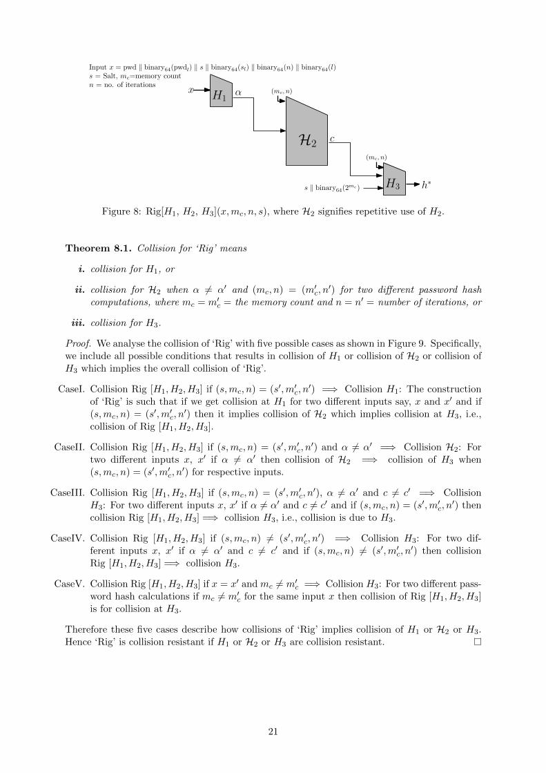
In the design of ‘Rig’ (see Figure 8) we define three different functions, H1, H2 and H3. Theinput of H1 is x where x is the concatenation of password, 64-bit value of password length,salt, 64-bit value of salt length, 64-bit value of n (number of iterations) and 64-bit value of theoutput length of password hash. The output of H1 is α. The function H2 signifies the repetitivecomputation of function H2 at setup phase and iterative transformation phase (see Figure 1)and generates the output c which is the output of iterative transformation phase. Therefore theinputs of H2 are α, mc and n, where mc is the number of memory count and n, the numberof iterations used. Finally H3 takes the concatenation of a 64-bit value which is the functionof mc and n, output of H2, the value salt and 64-bit value of 2mc and produces the output ofpassword hash. Here we are considering round r = 1 (w.l.o.g). This is because, different valuesof round, say r and r′ implies collision of H3.
20
H1xH1
α
H1
cH2
(mc, n)
H1H3 h∗
(mc, n)
Input x = pwd ‖ binary64(pwdl) ‖ s ‖ binary64(sl) ‖ binary64(n) ‖ binary64(l)s = Salt, mc=memory countn = no. of iterations
s ‖ binary64(2mc)
Figure 8: Rig[H1, H2, H3](x,mc, n, s), where H2 signifies repetitive use of H2.
Theorem 8.1. Collision for ‘Rig’ means
i. collision for H1, or
ii. collision for H2 when α 6= α′ and (mc, n) = (m′c, n′) for two different password hash
computations, where mc = m′c = the memory count and n = n′ = number of iterations, or
iii. collision for H3.
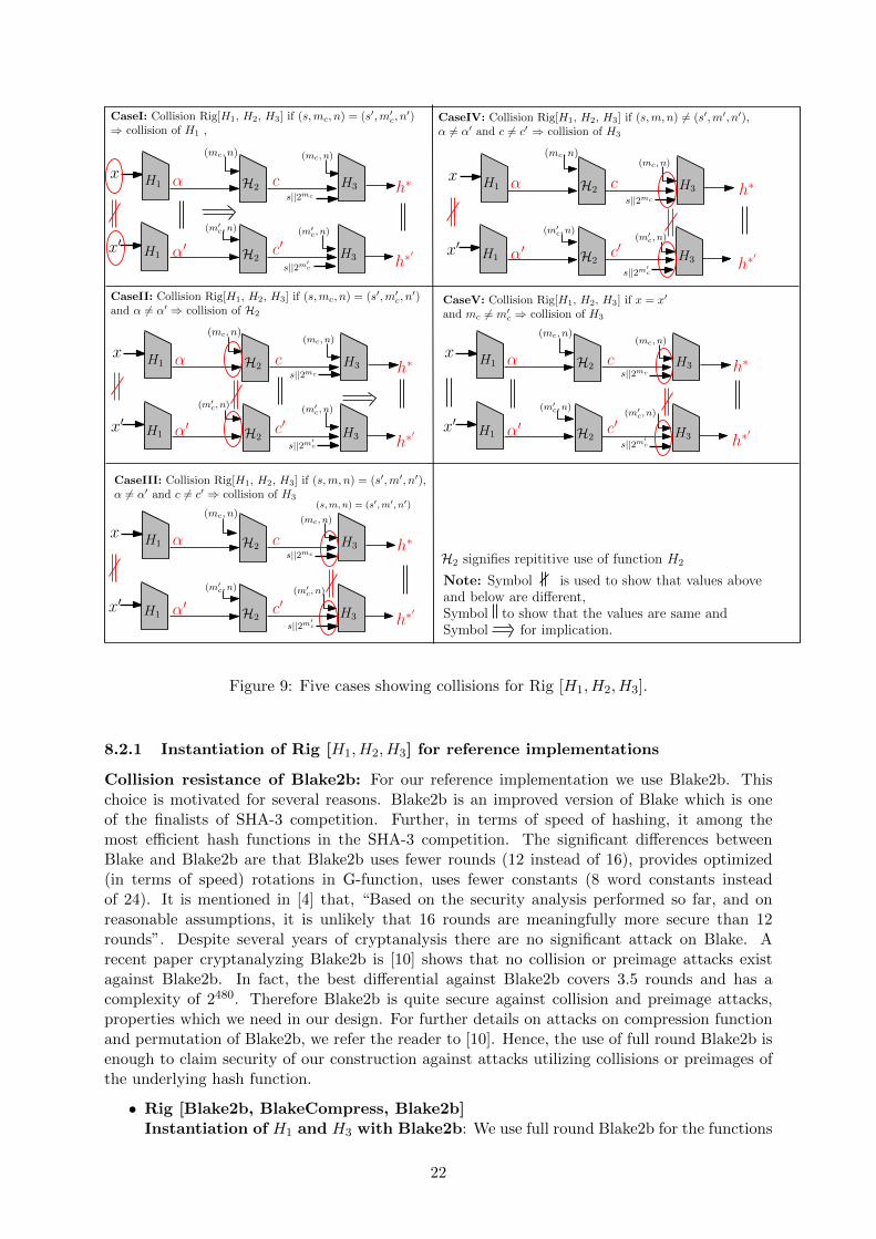
Proof. We analyse the collision of ‘Rig’ with five possible cases as shown in Figure 9. Specifically,we include all possible conditions that results in collision of H1 or collision of H2 or collision ofH3 which implies the overall collision of ‘Rig’.
CaseI. Collision Rig [H1, H2, H3] if (s,mc, n) = (s′,m′c, n′) =⇒ Collision H1: The construction
of ‘Rig’ is such that if we get collision at H1 for two different inputs say, x and x′ and if(s,mc, n) = (s′,m′c, n
′) then it implies collision of H2 which implies collision at H3, i.e.,collision of Rig [H1, H2, H3].
CaseII. Collision Rig [H1, H2, H3] if (s,mc, n) = (s′,m′c, n′) and α 6= α′ =⇒ Collision H2: For
two different inputs x, x′ if α 6= α′ then collision of H2 =⇒ collision of H3 when(s,mc, n) = (s′,m′c, n
′) for respective inputs.
CaseIII. Collision Rig [H1, H2, H3] if (s,mc, n) = (s′,m′c, n′), α 6= α′ and c 6= c′ =⇒ Collision
H3: For two different inputs x, x′ if α 6= α′ and c 6= c′ and if (s,mc, n) = (s′,m′c, n′) then
collision Rig [H1, H2, H3] =⇒ collision H3, i.e., collision is due to H3.
CaseIV. Collision Rig [H1, H2, H3] if (s,mc, n) 6= (s′,m′c, n′) =⇒ Collision H3: For two dif-
ferent inputs x, x′ if α 6= α′ and c 6= c′ and if (s,mc, n) 6= (s′,m′c, n′) then collision
Rig [H1, H2, H3] =⇒ collision H3.
CaseV. Collision Rig [H1, H2, H3] if x = x′ and mc 6= m′c =⇒ Collision H3: For two different pass-word hash calculations if mc 6= m′c for the same input x then collision of Rig [H1, H2, H3]is for collision at H3.
Therefore these five cases describe how collisions of ‘Rig’ implies collision of H1 or H2 or H3.Hence ‘Rig’ is collision resistant if H1 or H2 or H3 are collision resistant.
21
H1
H1
H2
H2
c
c′
H3
H3
h∗
h∗′
h∗
h∗′x′
x
h∗
h∗′
CaseIII: Collision Rig[H1, H2, H3] if (s,m, n) = (s′,m′, n′),α 6= α′ and c 6= c′ ⇒ collision of H3
h∗
h∗′
h∗
h∗′
CaseV: Collision Rig[H1, H2, H3] if x = x′
and mc 6= m′c ⇒ collision of H3
(m′c, n)
α′
α H1
H1
H2
H2
c
c′
H3
H3x′
x
(m′c, n)
α′
α
H1
H1
H2
H2
c
c′
H3
H3x′
x
α′
α H1
H1
H2
H2
c
c′
H3
H3x′
x
(m′c, n)
α′
α
H1
H1
H2
H2
c
c′
H3
H3x′
x
(m′c, n)
α
(s,m, n) = (s′,m′, n′)
s||2mc
s||2mc
s||2m′c
CaseIV: Collision Rig[H1, H2, H3] if (s,m, n) 6= (s′,m′, n′),α 6= α′ and c 6= c′ ⇒ collision of H3
(mc, n)
(m′c, n)
(mc, n)
(m′c, n)
(mc, n)
(mc, n)
(mc, n)
α′
s||2m′c
s||2mc
s||2mc
s||2m′c
s||2mc
s||2m′cs||2m′
c
(mc, n)
(mc, n)
(mc, n)
(mc, n)
(mc, n)
(m′c, n)
CaseII: Collision Rig[H1, H2, H3] if (s,mc, n) = (s′,m′c, n
′)and α 6= α′ ⇒ collision of H2
CaseI: Collision Rig[H1, H2, H3] if (s,mc, n) = (s′,m′c, n
′)⇒ collision of H1 ,
(m′c, n)
(m′c, n)
(m′c, n)
Note: Symbol is used to show that values aboveand below are different,Symbol to show that the values are same andSymbol for implication.
H2 signifies repititive use of function H2
Figure 9: Five cases showing collisions for Rig [H1, H2, H3].
8.2.1 Instantiation of Rig [H1, H2, H3] for reference implementations
Collision resistance of Blake2b: For our reference implementation we use Blake2b. Thischoice is motivated for several reasons. Blake2b is an improved version of Blake which is oneof the finalists of SHA-3 competition. Further, in terms of speed of hashing, it among themost efficient hash functions in the SHA-3 competition. The significant differences betweenBlake and Blake2b are that Blake2b uses fewer rounds (12 instead of 16), provides optimized(in terms of speed) rotations in G-function, uses fewer constants (8 word constants insteadof 24). It is mentioned in [4] that, “Based on the security analysis performed so far, and onreasonable assumptions, it is unlikely that 16 rounds are meaningfully more secure than 12rounds”. Despite several years of cryptanalysis there are no significant attack on Blake. Arecent paper cryptanalyzing Blake2b is [10] shows that no collision or preimage attacks existagainst Blake2b. In fact, the best differential against Blake2b covers 3.5 rounds and has acomplexity of 2480. Therefore Blake2b is quite secure against collision and preimage attacks,properties which we need in our design. For further details on attacks on compression functionand permutation of Blake2b, we refer the reader to [10]. Hence, the use of full round Blake2b isenough to claim security of our construction against attacks utilizing collisions or preimages ofthe underlying hash function.
• Rig [Blake2b, BlakeCompress, Blake2b]Instantiation of H1 and H3 with Blake2b: We use full round Blake2b for the functions
22

H1 and H3. We need collision resistance of both the functions for the security of ‘Rig’.Use of Blake2b allows us to claim collision resistance of H1 and H3 [10].
Instantiation of H2 with BlakeCompress: The function H2 as shown in Figure 8signifies the repetitive computations of the function H2 and inputs of H2 are α,mc, n.Theorem 8.1 shows that collision ofH2 implies collision of ‘Rig’ only if H1 gives two distinctoutputs say, α, α′ for two different inputs x 6= x′ while corresponding values (mc, n) =(m′c, n
′). We use first round of Blake2b compression function for the implementation ofH2 as shown in Figure 2.
For finalization phase we omit the feed-forward xor’ing as explained in Blake2b (see Fig-ure 3). This choice of implementation is to improve the performance, but it does notpreserve the onewayness as there is no feed-forward xor’ing. In this case it would appearthat backward calculation is easy as H2 computation is then reversible. But due to thedesign of ‘Rig’ it is very difficult to perform these backward computations as input valuesof H2 are arrays a and k and depends on their values at previous iteration (see Figure 1).Therefore, we only have the freedom to guess the values of array a and k to move back-ward with reverse calculation for the last iteration, say i = n. Last iteration n will fix thevalues of iteration (n− 1) as values are dependent. So we lose the freedom of guessing thevalues from iteration (n− 1) and onwards and the backward computations become hard.Hence omitting the feed forwardness can compromise the onewayness but the design of thescheme provides no security loss. Now consider two distinct inputs of H2 as α = H1(x)and α′ = H1(x
′) for x 6= x′.
H2 H2
1 2
(m+ 1) (m+ 2)
k[1]k[0] k[m-1]k[2]
α
t t tt
h0a[0] a[1] a[m-1]
H2
m
H2H2
SetupPhase:
α α
Figure 10: Setup phase uses m inputs generated from α.
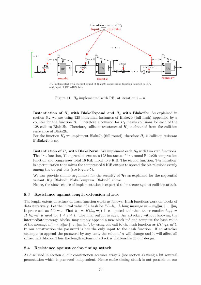
Figure 10 shows that m = 2mc number of computations of H2 of the setup phase aregenerated from these different α or α′ and it will be difficult to find collision everywhereas values generated from two different inputs are usually expected to be different. Thevalues of array a and k are generated from α or α′ and influence further calculations.Now, consider the last iteration of iterative transformation phase, i.e., the last layer of 2mc
computations of H2 as shown in Figure 11. All these H2 calls use single round Blake2band are generated from the same value α or α′. The input values influenced by α or α′ areshown in red color and most of them will have nonzero difference. We can visualize thisscenario as similar to the Blake2b construction, instead of 12 rounds using 2mc rounds. Useof comparatively large number of rounds provides enough security. Since we expect theparameter mc ≥ 10, we will have 1024 rounds of Blake2b compression function. Therefore,we can expect H2 to be collision resistant.
Therefore the choice of reduced round Blake2b does not affect the collision resistance ofthe design.
• Rig [BlakeExpand, BlakePerm, Blake2b]
23
Iteration i = n of H2
Input: α (512 bits)
t t t
k[br[2]]
t
round-1 round-2 round-2mc
i= n
(nm+ 2) (n+ 1)m0 0 0
RF1RF1 RF1
(nm+ 1)
H2 implemented with the first round of Blake2b compression function denoted as RF1
and input of RF1=1024 bits
H2 H2 H2
k[br[0]] k[br[1]] k[br[m− 1]]
Figure 11: H2 implemented with RF1 at iteration i = n.
Instantiation of H1 with BlakeExpand and H3 with Blake2b: As explained insection 6.2 we are using 128 individual instances of Blake2b (full hash) appended by acounter for the function H1. Therefore a collision for H1 means collisions for each of the128 calls to Blake2b. Therefore, collision resistance of H1 is obtained from the collisionresistance of Blake2b.For the function H3 we implement Blake2b (full round), therefore H3 is collision resistantif Blake2b is so.
Instantiation of H2 with BlakePerm: We implement each H2 with two step functions.The first function, ‘Compression’ executes 128 instances of first round Blake2b compressionfunction and compresses total 16 KiB input to 8 KiB. The second function, ‘Permutation’is a permutation that mixes the compressed 8 KiB output to spread the bit-relations evenlyamong the output bits (see Figure 5).
We can provide similar arguments for the security of H2 as explained for the sequentialvariant, Rig [Blake2b, BlakeCompress, Blake2b] above.Hence, the above choice of implementation is expected to be secure against collision attack.
8.3 Resistance against length extension attack
The length extension attack on hash function works as follows. Hash functions work on blocks ofdata iteratively. Let the initial value of a hash be IV =h0. A long message m = m0‖m1‖ . . . ‖ml
is processed as follows. First h1 = H(h0,m0) is computed and then the recursion hi+1 =H(hi,mi) is used for 1 ≤ i ≤ l. The final output is hl+1. An attacker, without knowing theintermediate message blocks, may simply append a new block m∗ and compute the hash valueof the message m′ = m0‖m1‖ . . . ‖ml‖m∗, by using one call to the hash function as H(hl+1,m
∗).In our construction the password is not the only input to the hash function. If an attackerattempts to append the password by any text, the value of α will change and it will affect allsubsequent blocks. Thus the length extension attack is not feasible in our design.
8.4 Resistance against cache-timing attack
As discussed in section 5, our construction accesses array k (see section 4) using a bit reversalpermutation which is password independent. Hence cache timing attack is not possible on our
24

costruction.Further, since the only primitive used in our scheme is a secure hash function, the security
of our scheme can be formulated in terms of the security of the underlying hash function. Withthe current state-of-the-art we have the possibility of using SHA-3 implementation, or even anyof the other finalists of SHA-3 competition, which are resilient to side-channel attacks. Thusour scheme resists cache timing attacks.
8.5 Resistance against denial-of-service attack
In computing, a denial-of-service (DoS) attack is an attempt to make a machine or networkresource unavailable to its intended users. This is possible by making the server busy injectinglots of request for some resource consuming calculation. It is quite easy if the server uses someslow password hashing technique for authentication. To handle such situations, the server-relieftechnique can provide some relief to the server from heavy calculations as the client will do theheavy part of the algorithm. This way we can reduce the chances of DoS attacks with slowpassword hashing schemes.
9 Intellectual property statement
We state that the scheme proposed in this report, Rig, is and will always remain availableworldwide on a royalty free basis. Furthermore, we are unaware of any deliberately hiddenweaknesses and any patent or patent application that covers the use or implementation of thesubmitted algorithm.
References
[1] Password Hashing Competition (PHC), 2014. https://password-hashing.net/index.
html.
[2] Leonardo C. Almeida, Ewerton R. Andrade, Paulo S. L. M. Barreto, and MarcosA. Simplıcio Jr. Lyra: Password-Based Key Derivation with Tunable Memory and Process-ing Costs. IACR Cryptology ePrint Archive, 2014:30, 2014.
[3] Jean-Philippe Aumasson, Samuel Neves, Zooko Wilcox-O’Hearn, and Christian Winnerlein.BLAKE2: Simpler, Smaller, Fast as MD5. In ACNS, pages 119–135, 2013.
[4] Jean-Philippe Aumasson, Samuel Neves, Zooko Wilcox-O’Hearn, and Christian Winnerlein.BLAKE2: simpler, smaller, fast as MD5. IACR Cryptology ePrint Archive, 2013:322, 2013.
[5] Carlos Carvalho. The gap between processor and memory speeds. In Proc. of IEEE Inter-national Conference on Control and Automation, 2002.
[6] Joan Daemen and Vincent Rijmen. A new MAC construction ALRED and a specificinstance ALPHA-MAC. In Fast Software Encryption: 12th International Workshop, FSE2005, Paris, France, February 21-23, 2005, Revised Selected Papers, pages 1–17, 2005.
[7] Markus Durmuth, Tim Guneysu, Markus Kasper, Christof Paar, Tolga Yalcin, and RalfZimmermann. Evaluation of Standardized Password-Based Key Derivation against ParallelProcessing Platforms. In Sara Foresti, Moti Yung, and Fabio Martinelli, editors, ESORICS,volume 7459 of Lecture Notes in Computer Science, pages 716–733. Springer, 2012.
[8] Christian Forler, Stefan Lucks, and Jakob Wenzel. The Catena Password Scrambler. Sub-mission to Password Hashing Competition (PHC), 2014.
25

[9] Jim Gray and Prashant Shenoy. Rules of Thumb in Data Engineering. Technical Re-port, MS-TR-99-100, Microsoft Research, Advanced Technology Division. December 1999,Revised March 2000.
[10] Jian Guo, Pierre Karpman, Ivica Nikolic, Lei Wang, and Shuang Wu. Analysis of BLAKE2.In Josh Benaloh, editor, Topics in Cryptology - CT-RSA 2014 - The Cryptographer’s Trackat the RSA Conference 2014, San Francisco, CA, USA, February 25-28, 2014. Proceedings,volume 8366 of Lecture Notes in Computer Science, pages 402–423. Springer, 2014.
[11] Thomas Lengauer and Robert Endre Tarjan. Upper and lower bounds on time-space trade-offs. In Proceedings of the 11h Annual ACM Symposium on Theory of Computing, April 30- May 2, 1979, Atlanta, Georgia, USA, pages 262–277, 1979.
[12] Colin Percival. Stronger key derivation via sequential memory-hard functions. In BSDCon,2009. http://www.bsdcan.org/2009/schedule/attachments/87_scrypt.pdf.
[13] Niels Provos and David Mazieres. A Future-Adaptable Password Scheme. In USENIXAnnual Technical Conference, FREENIX Track, pages 81–91. USENIX, 1999.
[14] Robert R. Schaller. Moore’s law: past, present, and future. IEEE Spectrum, June 1997.
[15] Meltem Snmez Turan, Elaine Barker, William Burr, and Lily Chen. NIST: Special Pub-lication 800-132, Recommendation for Password-Based Key Derivation. Computer Secu-rity Division Information Technology Laboratory. http://csrc.nist.gov/publications/nistpubs/800-132/nist-sp800-132.pdf.
10 Appendix
10.1 ChangeLog
From Rig-version 1.0 to Rig-version 2.0
This version of the report includes some changes suggested by mails on PHC discussionforum. These changes are listed below.
• References [8, 11] are added for bit-reversal permutation of Algorithm 1 in section 2.
• We modified the construction slightly to handle the error of wrong usage of bit-reversalpermutation in the earlier version. Algorithm 2 (page no. 6) is accordingly modified, alongwith its graphical description. Few more descriptive steps (line 19 to 22) are added inAlgorithm 2.
• Input of initialization phase is changed from x=pwd ‖ s ‖ binary64(n) ‖ binary64(l) tox= pwd ‖ binary64(pwdl) ‖ s ‖ binary64(sl) ‖ binary64(n) ‖ binary64(l).
• On page no. 8 a sentence has been changed to: ”Therefore, a password hashing schemeshould have password-independent memory access patterns and to follow this requirementwe use bit reversal permutation, as in [8]”, (This is as per the suggestion of Mr. Cox).
• An optimized variant of ‘Rig’, Rig [BlakeExpand, BlakePerm, Blake2b] with its detaileddescription is provided in Section 6.
• Section 7 includes a graph showing the comparison of ‘Rig’ with ‘Scrypt’ and also in-cludes the performance figure of reference implementation of general ‘Rig’, instantiatedas Rig [Blake2b, BlakeCompress, Blake2b] and the optimized variant, Rig [BlakeExpand,BlakePerm, Blake2b].
26

• We have followed more descriptive approach to provide the security analysis of ‘Rig’ forlow-memory attack in section 8.1.
• Proof of collision resistance for ‘Rig’ is included in Section 8.2.
• Rectified the (minor) implementation issues pointed out by Mr. Cox in our reference ‘C’implementation. The reference code is thus changed.
• The bit-reversal permutation is now implemented using the ‘Catena’ style (as per thesuggestion of Mr. Cox).
• Writing has been changed at a few places in the document, e.g., the note at the end ofpoint 9 of Section 5, the last but one paragraph of Section 1, etc.
• The reference implementation is now available at https://github.com/arpanj/Rig.
• An acknolwledgements section is added in the document.
Acknowledgements
We would like to thank Bill Cox for his numerous comments on Rig version 1.0 and DmitryKhovratovich for bringing reference [11] to our attention. We would also like to thank thenumerous researchers and developers whose comments on the PHC mailing list improved ourunderstanding of the challenges faced in password hashing and the methods to tackle them.
27