rheological analysis of blast furnace slag · pdf filerheological measurements were carried...
TRANSCRIPT
1
Rheological Analysis Of Blast Furnace Synthetic Slag Admixtures Of Al2o3
Piotr Migas*, Marta Korolczuk-Hejnak, Mirosław Karbowniczek
Department of Ferrous Metallurg, Faculty of Metal Engineering and Industrial Computer Science, AGH-University of Science and Technology, 30-059 Krakow, Poland
Abstract: The nature and properties of ionic liquid solutions - metallurgical slags (used in the pig iron and steel
production) affect the quality and processing time of the final product. The reactions mostly occur in the interfaces
between metal-slag, slag-gas, slag-solid, during their contacts, often under dynamic conditions, rarely in the static state.
It is generally assumed that liquid slags exhibit a behaviour similar to ideal Newtonian viscous flow. At the same time it
is assumed that the liquid slag has a structural likeness to synthetic polymers, which are not Newtonian fluids. The
authors tried to verify the prevailing views and hypotheses. The main study concerned the slag system: CaO-SiO2-
MgO-Al2O3, when the content of Al2O3 was raised to ca. 25% in liquid and semi-liquid state.
Measurements were performed using Searle’s method of concentric cylinder systems. Graphite measuring systems
were used for testing with two types of spindles: smooth and perforated.
Rheological measurements were carried out for five slag systems in the temperature range between 1310-1500oC, the
shear rate values were changed in the wide range between 1s-1 to 150s-1.
FactSage application was used to calculate the amount of solid phases precipitating from the slag volume for different
chemical compositions in different temperatures. Based on the rheological results, it was found that the analysed slag
systems in the completely liquid temperature range show similarity to the perfectly viscous Newtonian body. However,
in the temperature range in which the solid phases occurred in the slag the analyzed systems show non-Newtonian
behaviour.
Keywords: liquid slags, rheology, non-Newtonian flow,
1. Introduction
Viscosity is one of the basic physical properties of metallurgical processes involving metal and slag liquid phases. It
has a direct influence on the kinetics of reactions taking place between liquid metal and slag as well as on the flow of
these phases in metallurgical aggregates. That is why this property is a key parameter of the already existing
mathematical models and the ones that are currently being developed. The rheological character of liquid slag should be
defined not only on the basis of changes in chemical composition and temperature but also using rheological parameters
such as t –time during which the force affects the system, τ – the shear stress , γ – the shear rate [1].
The rheological parameters of real metallurgical processes can be extremely hard to measure. These difficult to
measure parameters include: the dynamics of the influence of the arc on the properties of liquid steel and slag, the
dynamics of the influence of the reduction gas on the liquid slag and pig iron in the blast furnace, the phenomena
2
regarding liquid and semi-liquid products moving down the blast furnace in counter-flow with the reduction gas and
then filling the voids between the pieces of coke.
All these factors influence the liquid slag and pig iron with a certain dynamic force and result in the occurrence of the
shear stress in the layers of moving slag – thus changing the dynamic viscosity coefficient of the slag and in certain
cases its rheological character. It is commonly assumed that fully liquid slag, which is a Newtonian fluid, does not
change its viscosity under the influence of an applied force. Its viscosity was also influenced by the content of solid
elements in the fluid. The viscosity is also affected by the contents of solid elements which precipitated while the
temperature was being decreased, in the course of chemical reactions, due to changes in chemical composition and as a
result of elements entering slag from the outside (e.g. coal dust, carbides, nitrides insoluble in slag).
Solid-liquid slag systems are present in many metallurgical processes such as: the blast furnace process - PCI, the
cohesion zone and slag dripping; the arc furnace process – slag foaming, slag in the production of chrome steel; COS –
steel casting, casting powder, pig iron and steel refining – 3D technology, desulphurization, dephosphorization,
desilicanization. All these processes involve solid elements which precipitated from the solution or which were
introduced to the slag system.
The literature contains a significant amount of measurement data concerning the dynamic viscosity of metallurgical
slag in case of fully liquid slag systems [2-5]. Their authors did research into the influence of the chemical composition,
basicity and temperature on viscosity. Few research centres [6,7] undertook the complicated research into the changes
of the dynamic viscosity coefficient as a rheological property of the liquid or solid-liquid multi-component slag systems.
Rheology is a study of the material deformation and its transition to plastic state. Rheology focuses on such issues as:
changing relations between stress and deformation in the function of time, changing viscosity, separation and mixing of
substance particles affected stress. The subject of rheological research, depending on the field of course, can vary from:
metal alloys, different types of emulsions, pastes, slurries, geological sediments, polymer solutions, foams, etc. This
research mostly deals with not homogenous materials [14]. Rheology is a study of two different types of fluids [8]:
• Newtonian fluids– (ideal viscosity) which show a linear relationship between the shear stress and the shear rate,
• Non-Newtonian fluids – which show non-linear relationship between the shear stress and changes in the
shear rate.
Newtonian fluids are characterized by a stable viscosity in the course of the flow, the independence of the
deformation rate and the repeatability of viscosity value in the course of subsequent identical flows. The viscosity of
non-Newtonian fluids is referred to as apparent viscosity. It is independent of the deformation rate, duration and
pressure. In reality most fluids are non-Newtonian ones.
The rheological description of fluids includes viscous and elastic features. The viscous features can be determined by
defining the flow curve, i.e. the relation between the shear stress (triggered by the shearing fluid) and the shear rate
(velocity gradient existing in the flowing liquid). In order to determine the elastic features it is necessary to measure the
normal stress in the course of a given viscous flow. Such analysis allows to determine the relationship between the
deformation, the shear rate and the shear stress.
3
Recently researchers have been developing and describing many models used to determine the viscosity of
aluminosilicate slag: Urbaina, KTH, Iidy, QCV [8-13].
The viscosity (η) of slag is distinctly dependent on the temperature and structure of fluid [14]. It is a measure of the
ability of slag to flow when the shear stress is applied. Most slag and metallic fluids do not show characteristics of
Newtonian fluids, in case of which viscosity is independent of the shear rate [14]. As a result viscosity is defined by the
Newton’s equation (1) as a constant of the proportional relationship between the shear stress (τxy) and the normal
velocity gradient to the shear stress (dydvx ).
=
dydvx
xy ητ (1)
When the layers in the fluid shear, the bonds break. This is a process activated thermally and it is expressed by the
Arrhenius equation (2). It is characterized by coefficient AA and activation energy EA:
RTE
A
A
eA ⋅=η (2)
Liquid slag consists of, among others, discontinuous ionic structures whose energy is closely connected to the type of
ions and ionic complexes present in the system as well as to the interionic forces. Due to the fact that the type and size
of ions changes with temperature, the activation energy changes significantly with temperature, too.
The Einstein-Roscoe equation (3) is commonly used to describe the viscosity of slag containing dispersed solid phase.
The equation below can be used to estimate the viscosity of partially crystallized slag containing up to 30% solid
fraction in the volume of the system.
nSLS R −−= )1( θηη (3)
where ηS refers to the apparent viscosity of the suspension in the fluid and solid elements and and ηS to the viscosity of
the fully liquid phase, ΦS is a volume fraction of the solid phase. For identical size of spherical particles R and n in the
equation amount to 1.35 and 2.5 respectively. The reciprocal of the R value in the physical sense refers to the maximum
amount of solid phase which the fluid can hold before the viscosity reaches an infinitely large value. The equation was
introduced with an assumption that the particles were dispersed evenly in the fluid [6].
The viscosity is a measure of the resistance of the vicious flow and it is to a large extent dependent on the mobility of
elements present in the fluid, such as atoms, molecules or ions which respectively reflect: the bond, the size and the
configuration of the fluid components. In such a system one can observe a strong relationship between the measured
viscosity and the structure. Slag is partially a polymer substance and some of its properties (e.g. viscosity, density,
thermal and electric conduction) are dependent on its structure.
A. Shankar and associates [5] conducted research into the dynamic viscosity coefficient taking into consideration the
changes in the rotary velocity of the spindle (5 types of rotary velocity ranging from 4 to 80 rpm) for slag systems:
4
CaO-SiO2-MgO-Al2O3 and CaO-SiO2-MgO-Al2O3-TiO2 in the basicity range: 0.72 – 1.23 and in temperature range:
1650 to 1873K. Liquidus temperature was calculated using Thermo-Calc software so that the systems would be fully
liquid.
The increase in viscosity value (at the temperature of 1673K) suggested the presence of solid particles in the system.
Their amount, however, was not defined. The authors put forward a thesis that viscosity depends to a large extent on the
amount and size of solid particles and ions present in the system. The viscosity value is also affected by the degree of
slag polymerization, which is in turn dependent on the silica activity – i.e. the possible Si-O-Si bonds as well as oxygen
ions O2-. The change in rotary velocity of the revolving element did not affect the dynamic viscosity of slag.
A. Kondratiev and associates [6] set out to verify the Einstein-Roscoe equation and conducted research into 4
different partially crystallized slag systems (among others Al2O3-FeO-SiO2 ) during the cooling process from 1773 to
1633K and the heating process from 1633 to 1723K. In the course of continuous measurements (the value of torque
changed with temperature) researchers noticed a sudden increase in viscosity at the temperature of approx. 1668K. That
is when solid phase began to precipitate in slag. The parameters adjusted to model (3) are as follows: R = 1.29 and n=
2.04 and are comparable to the Roscoe model values.
G. Handfield, G.G. Charette, H.Y. Lee [14-17] carried out research into the viscosity of liquid slag containing
dispersed solid particles. The authors analysed titanium oxide doped blast furnace slag and fluxes (of the Sorelflux type).
They observed a dramatic increase in the dynamic viscosity coefficient, which they interpreted as an intensive
crystallization of titanium compounds.
It is said that slag remains a Newtonian fluid but in case of certain ranges of chemical composition, temperature and
deformations it shows the characteristics of pseudo-Newtonian fluid – it sometimes shows characteristics of viscous-
elastic fluids.
According to Y. Sasaki and associates [1] the energy supplied to the deformation of the liquid slag system CaO-SiO2-
Al2O3 is used for the dissipation in the “viscous part” while the fluid in on the move. Some of the energy is gathered in
the so called “elastic part” of the system. These are typical characteristics of viscous-elastic bodies. The authors
categorize liquid fluxes, casting powders and slag as clearly non-Newtonian fluids. Liquid slag phases show strong
tendencies to polymerize or depolymerize the internal structure, tendencies which affect their rheological description [1].
S. Wright, L. Zhang, S. Sun, S. Jahanshahi [7] conducted research into the viscosity of slag 28%CaO-10%MgO-
20%Al2O3-42%SiO2 with the addition of solid particles of spinel (MgAl2O4). The shear rate was changed within the
range of 0.5 to 3s-1 for less than 10% of the solid phase and the range of 0.3 to 1s-1 for bigger amounts of solid phase.
When the content of solid phase was low (up to 10%) the apparent viscosity decreased. In the extreme case of 22% of
solid phase the viscosity decreased twofold in comparison to the maximum value while the shear rate was increasing.
In the case of a 10% or higher content of solid phase the system showed the behaviour of the Bigham’s type (i.e. the
shear stress increased linearly with the grow in the shear rate but there was a residual shear stress for zero shear rate).
5
The residual shear stress suggests the existence of a flow boundary (up to 3Pa depending on the amount and size of
solid phase).
S. Seok, S. Jung, Y. Lee, D. Min [3] also studied the viscosity of CaO-8%MgO-FeO-Al2O3-SiO2 in solid-liquid
dispersed system saturated with 2CaO⋅SiO2 in a temperature range of 1673-1873K. They tested viscosity measurements
in the temperature of 1873K for 3 different rotary velocities of the spindle (30, 60, 100 rpm). They claimed that the
results of viscosity do not depend on the rotary velocity. The apparent viscosity of slag is dependent on the volume
fraction of solid phase – estimated on the basis of slag composition.
D. Xie, Y. Mao, Y. Zhu [18] did research into rheological properties of blast furnace slag containing 17-33% TiO2 in
reduction conditions. They measured the changes in the concentration of reduction products and corresponding changes
of slag properties. At first Ti2O3 was produced and a slight increase in viscosity was observed. In the course of further
reduction one could notice TiO and TiC which is insoluble in slag. This is when viscosity increased significantly
(independently of the amount of TiC). The authors suggested the existence of a solid solution of TiC-TiO, which
triggered a significant increase in the volume of precipitated solid phase, and consequently an excessive increase in the
viscosity of the system.
Despite a significant amount of research conducted into the viscosity of slag systems the data available still seem to
be insufficient to fully understand the structure and viscous properties of slag commonly used in metallurgical processes.
In case of complex slag systems the experimental data are only available for selected temperatures and for a narrow
range of concentration. Due to difficult high temperature conditions comprehensive rheological research into slag is
conducted in few centres and on a small scale. Each study of this sort brings new results and contributes to a better
understanding of the rheological properties of slag
2. Experimental method
In order to measure the dynamic viscosity coefficient a force needs to be applied to the liquid system, and as a result
the system is set into motion. The application of the force causes one layer of fluid to be transported towards another.
Longer chains in fluid and polymerization cause the measurements to be more complicated. The dynamic viscosity is
the best property of liquid glass and slag [20] when it comes to analysing the internal structure of these fluids.
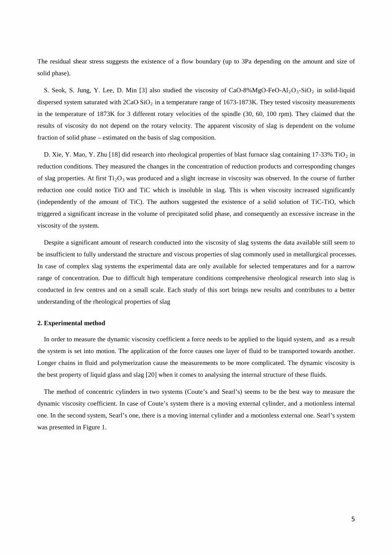
The method of concentric cylinders in two systems (Coute’s and Searl’s) seems to be the best way to measure the
dynamic viscosity coefficient. In case of Coute’s system there is a moving external cylinder, and a motionless internal
one. In the second system, Searl’s one, there is a moving internal cylinder and a motionless external one. Searl’s system
was presented in Figure 1.
6
Fig. 1 Concentric cylinder system
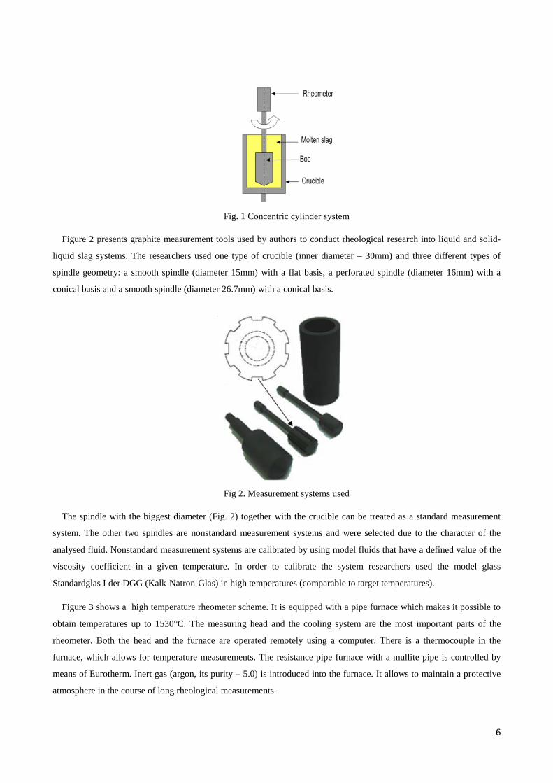
Figure 2 presents graphite measurement tools used by authors to conduct rheological research into liquid and solid-
liquid slag systems. The researchers used one type of crucible (inner diameter – 30mm) and three different types of
spindle geometry: a smooth spindle (diameter 15mm) with a flat basis, a perforated spindle (diameter 16mm) with a
conical basis and a smooth spindle (diameter 26.7mm) with a conical basis.
Fig 2. Measurement systems used
The spindle with the biggest diameter (Fig. 2) together with the crucible can be treated as a standard measurement
system. The other two spindles are nonstandard measurement systems and were selected due to the character of the
analysed fluid. Nonstandard measurement systems are calibrated by using model fluids that have a defined value of the
viscosity coefficient in a given temperature. In order to calibrate the system researchers used the model glass
Standardglas I der DGG (Kalk-Natron-Glas) in high temperatures (comparable to target temperatures).
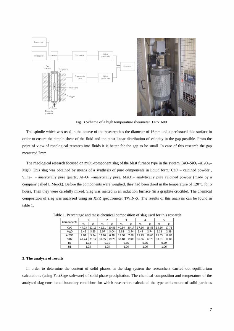
Figure 3 shows a high temperature rheometer scheme. It is equipped with a pipe furnace which makes it possible to
obtain temperatures up to 1530°C. The measuring head and the cooling system are the most important parts of the
rheometer. Both the head and the furnace are operated remotely using a computer. There is a thermocouple in the
furnace, which allows for temperature measurements. The resistance pipe furnace with a mullite pipe is controlled by
means of Eurotherm. Inert gas (argon, its purity – 5.0) is introduced into the furnace. It allows to maintain a protective
atmosphere in the course of long rheological measurements.
7
Fig. 3 Scheme of a high temperature rheometer FRS1600
The spindle which was used in the course of the research has the diameter of 16mm and a perforated side surface in
order to ensure the simple shear of the fluid and the most linear distribution of velocity in the gap possible. From the
point of view of rheological research into fluids it is better for the gap to be small. In case of this research the gap
measured 7mm.
The rheological research focused on multi-component slag of the blast furnace type in the system CaO–SiO2–Al2O3–
MgO. This slag was obtained by means of a synthesis of pure components in liquid form: CaO – calcined powder ,
SiO2 - analytically pure quartz, Al2O3 –analytically pure, MgO – analytically pure calcined powder (made by a
company called E.Merck). Before the components were weighed, they had been dried in the temperature of 120°C for 5
hours. Then they were carefully mixed. Slag was melted in an induction furnace (in a graphite crucible). The chemical
composition of slag was analysed using an XFR spectrometer TWIN-X. The results of this analysis can be found in
table 1.
Table 1. Percentage and mass chemical composition of slag used for this research
Components 1 2 3 4 5
% g % g % g % g % g CaO 44.23 22.11 41.61 20.81 40.34 20.17 37.66 18.83 35.56 17.78 MgO 6.46 3.23 6.07 3.04 5.88 2.94 5.49 2.74 5.18 2.59
Al2O3 7.07 3.54 12.76 6.38 15.60 7.80 21.29 10.65 25.65 12.83 SiO2 42.24 21.12 39.55 19.78 38.18 19.09 35.56 17.78 33.61 16.80 B3 1.03 0.91 0.86 0.76 0.69 B1 1.05 1.05 1.06 1.06 1.06
3. The analysis of results
In order to determine the content of solid phases in the slag system the researchers carried out equillibrium
calculations (using FactSage software) of solid phase precipitation. The chemical composition and temperature of the
analyzed slag constituted boundary conditions for which researchers calculated the type and amount of solid particles
8
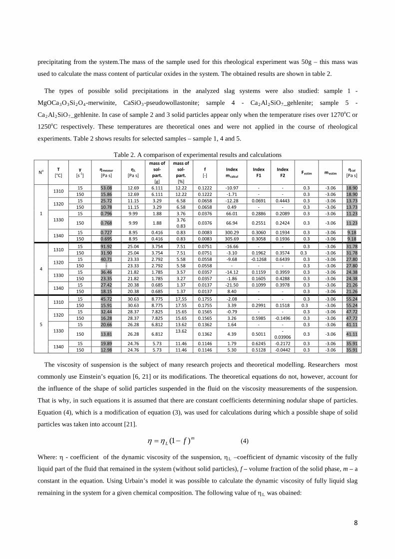
precipitating from the system.The mass of the sample used for this rheological experiment was 50g – this mass was
used to calculate the mass content of particular oxides in the system. The obtained results are shown in table 2.
The types of possible solid precipitations in the analyzed slag systems were also studied: sample 1 -
MgOCa3O3Si2O4-merwinite, CaSiO3-pseudowollastonite; sample 4 - Ca2Al2SiO7_gehlenite; sample 5 -
Ca2Al2SiO7_gehlenite. In case of sample 2 and 3 solid particles appear only when the temperature rises over 1270oC or
1250oC respectively. These temperatures are theoretical ones and were not applied in the course of rheological
experiments. Table 2 shows results for selected samples – sample 1, 4 and 5.
Table 2. A comparison of experimental results and calculations
No T
[°C] γ
[s-1] ηmeasur [Pa s]
ηL
[Pa s]
mass of sol-
part. [g]
mass of sol-
part. [%]
f [-]
Index mcalcul
Index F1
Index F2
Festim mestim ηcal
[Pa s]
1
1310 15 53.08 12.69 6.111 12.22 0.1222 -10.97 - - 0.3 -3.06 18.90
150 15.86 12.69 6.111 12.22 0.1222 -1.71 - - 0.3 -3.06 18.90
1320 15 25.72 11.15 3.29 6.58 0.0658 -12.28 0.0691 0.4443 0.3 -3.06 13.73
150 10.78 11.15 3.29 6.58 0.0658 0.49 - - 0.3 -3.06 13.73
1330 15 0.796 9.99 1.88 3.76 0.0376 66.01 0.2886 0.2089 0.3 -3.06 11.23
150 0.768 9.99 1.88 3.76 0.83
0.0376 66.94 0.2551 0.2424 0.3 -3.06 11.23
1340 15 0.727 8.95 0.416 0.83 0.0083 300.29 0.3060 0.1934 0.3 -3.06 9.18
150 0.695 8.95 0.416 0.83 0.0083 305.69 0.3058 0.1936 0.3 -3.06 9.18
4
1310 15 91.92 25.04 3.754 7.51 0.0751 -16.66 - - 0.3 -3.06 31.78
150 31.90 25.04 3.754 7.51 0.0751 -3.10 0.1962 0.3574 0.3 -3.06 31.78
1320 15 40.71 23.33 2.792 5.58 0.0558 -9.68 -0.1268 0.6439 0.3 -3.06 27.80
150 - 23.33 2.792 5.58 0.0558 - - - 0.3 -3.06 27.80
1330 15 36.46 21.82 1.785 3.57 0.0357 -14.12 0.1159 0.3959 0.3 -3.06 24.38
150 23.35 21.82 1.785 3.27 0.0357 -1.86 0.1605 0.4288 0.3 -3.06 24.38
1340 15 27.42 20.38 0.685 1.37 0.0137 -21.50 0.1099 0.3978 0.3 -3.06 21.26
150 18.15 20.38 0.685 1.37 0.0137 8.40 - - 0.3 -3.06 21.26
5
1310 15 45.72 30.63 8.775 17,55 0.1755 -2.08 - - 0.3 -3.06 55.24
150 15.91 30.63 8.775 17.55 0.1755 3.39 0.2991 0.1518 0.3 -3.06 55.24
1320 15 32.44 28.37 7.825 15.65 0.1565 -0.79 - - 0.3 -3.06 47.72
150 16.28 28.37 7.825 15.65 0.1565 3.26 0.5985 -0.1496 0.3 -3.06 47.72
1330 15 20.66 26.28 6.812 13.62 0.1362 1.64 - - 0.3 -3.06 41.11
150 13.81 26.28 6.812 13.62
0.1362 4.39 0.5011 -
0.03906 0.3 -3.06 41.11
1340 15 19.89 24.76 5.73 11.46 0.1146 1.79 0.6245 -0.2172 0.3 -3.06 35.91
150 12.98 24.76 5.73 11.46 0.1146 5.30 0.5128 -0.0442 0.3 -3.06 35.91
The viscosity of suspension is the subject of many research projects and theoretical modelling. Researchers most
commonly use Einstein’s equation [6, 21] or its modifications. The theoretical equations do not, however, account for
the influence of the shape of solid particles suspended in the fluid on the viscosity measurements of the suspension.
That is why, in such equations it is assumed that there are constant coefficients determining nodular shape of particles.
Equation (4), which is a modification of equation (3), was used for calculations during which a possible shape of solid
particles was taken into account [21].
mL f )1( −=ηη (4)
Where: η - coefficient of the dynamic viscosity of the suspension, ηL –coefficient of dynamic viscosity of the fully
liquid part of the fluid that remained in the system (without solid particles), f – volume fraction of the solid phase, m – a
constant in the equation. Using Urbain’s model it was possible to calculate the dynamic viscosity of fully liquid slag
remaining in the system for a given chemical composition. The following value of ηL was obained:
9
)1ln(
ln
fm L
−=
ηη
(5)
)21(323FF
Fm−−
= (6)
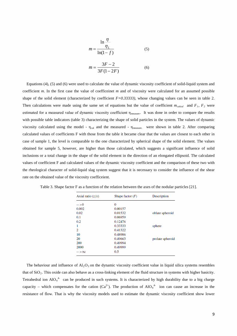
Equations (4), (5) and (6) were used to calculate the value of dynamic viscosity coefficient of solid-liquid system and
coefficient m. In the first case the value of coefficeinet m and of viscosity were calculated for an assumed possible
shape of the solid element (characterized by coefficient F=0.33333), whose changing values can be seen in table 2.
Then calculations were made using the same set of equations but the value of coefficient mcalcul and F1, F2 were
estimated for a measured value of dynamic viscosity coefficient ηmeasure. It was done in order to compare the results
with possible table indicators (table 3) characterizing the shape of solid particles in the system. The values of dynamic
viscosity calculated using the model - ηcal and the measured - ηmeasure. were shown in table 2. After comparing
calculated values of coefficients F with those from the table it became clear that the values are closest to each other in
case of sample 1, the level is comparable to the one characterized by spherical shape of the solid element. The values
obtained for sample 5, however, are higher than those calculated, which suggests a significant influence of solid
inclusions or a total change in the shape of the solid element in the direction of an elongated ellipsoid. The calculated
values of coefficient F and calculated values of the dynamic viscosity coefficient and the comparison of these two with
the rheological character of solid-liquid slag system suggest that it is necessary to consider the influence of the shear
rate on the obtained value of the viscosity coefficeient.
Table 3. Shape factor F as a function of the relation between the axes of the nodular particles [21].
The behaviour and influence of Al2O3 on the dynamic viscosity coefficient value in liquid silica systems resembles
that of SiO2. This oxide can also behave as a cross-linking element of the fluid structure in systems with higher basicity.
Tetrahedral ion AlO44- can be produced in such systems. It is characterized by high durability due to a big charge
capacity – which compensates for the cation (Ca2+). The production of AlO44- ion can cause an increase in the
resistance of flow. That is why the viscosity models used to estimate the dynamic viscosity coefficient show lower
10
viscosity by approx. 40% than the one obtained in the course of measurements. It is true, however, that there are few
experimental data available in literature to explain this discrepancy [21].
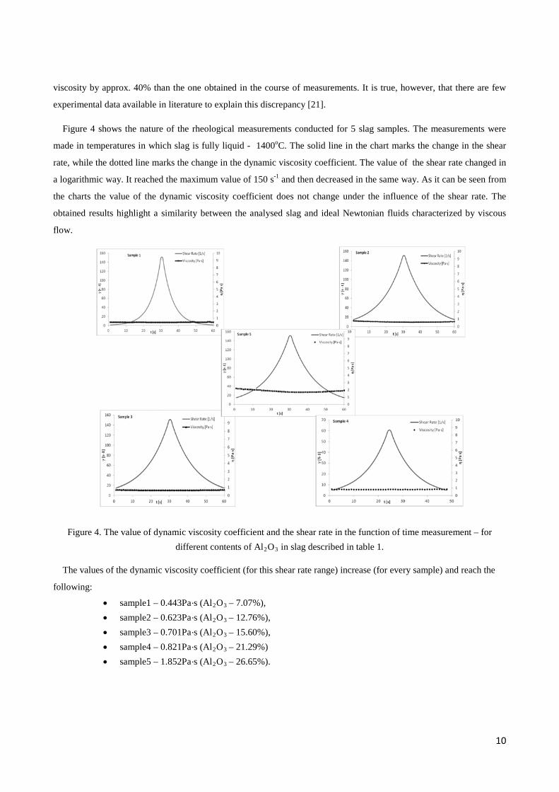
Figure 4 shows the nature of the rheological measurements conducted for 5 slag samples. The measurements were
made in temperatures in which slag is fully liquid - 1400oC. The solid line in the chart marks the change in the shear
rate, while the dotted line marks the change in the dynamic viscosity coefficient. The value of the shear rate changed in
a logarithmic way. It reached the maximum value of 150 s-1 and then decreased in the same way. As it can be seen from
the charts the value of the dynamic viscosity coefficient does not change under the influence of the shear rate. The
obtained results highlight a similarity between the analysed slag and ideal Newtonian fluids characterized by viscous
flow.
Figure 4. The value of dynamic viscosity coefficient and the shear rate in the function of time measurement – for different contents of Al2O3 in slag described in table 1.
The values of the dynamic viscosity coefficient (for this shear rate range) increase (for every sample) and reach the
following:
• sample1 – 0.443Pa·s (Al2O3 – 7.07%), • sample2 – 0.623Pa·s (Al2O3 – 12.76%), • sample3 – 0.701Pa·s (Al2O3 – 15.60%), • sample4 – 0.821Pa·s (Al2O3 – 21.29%) • sample5 – 1.852Pa·s (Al2O3 – 26.65%).
11
It can mean that when Al2O3 in the amount of 7.07 – 25.65% of the mass in the system (with a stable proportion
CaO/ SiO2) enters into anionic bonds, it behaves like a network modifier and increases the value of the dynamic
viscosity coefficient of the fully liquid slag.
Figure 5 and 6 present the results concerning the changes in the value of dynamic viscosity coefficient with time for
different shear rate values and different schemes of the changes presented in table 4.
Table 4. Chosen schedule of measurement.
Measurement stage
•
γ
[s-1]
Temp. [°C]
Step I 15 cooling/homogenisation Step II A) 15-150(log)
B) 150-15(log) Const.
Step III A) 15-180(log) B) 180-15(log)
Const.
Step IV A) 30, 60, 80, 120, 80, 60, 30, B) 5, 200, 15, 200, 15, 150, 15, 150,
Const.
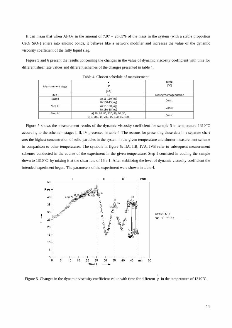
Figure 5 shows the measurement results of the dynamic viscosity coefficient for sample 5 in temperature 1310 oC
according to the scheme – stages I, II, IV presented in table 4. The reasons for presenting these data in a separate chart
are: the highest concentration of solid particles in the system in the given temperature and shorter measurement scheme
in comparison to other temperatures. The symbols in figure 5: IIA, IIB, IVA, IVB refer to subsequent measurement
schemes conducted in the course of the experiment in the given temperature. Step I consisted in cooling the sample
down to 1310°C by mixing it at the shear rate of 15 s-1. After stabilizing the level of dynamic viscosity coefficient the
intended experiment began. The parameters of the experiment were shown in table 4.
Figure 5. Changes in the dynamic viscosity coefficient value with time for different •
γ in the temperature of 1310°C.
12
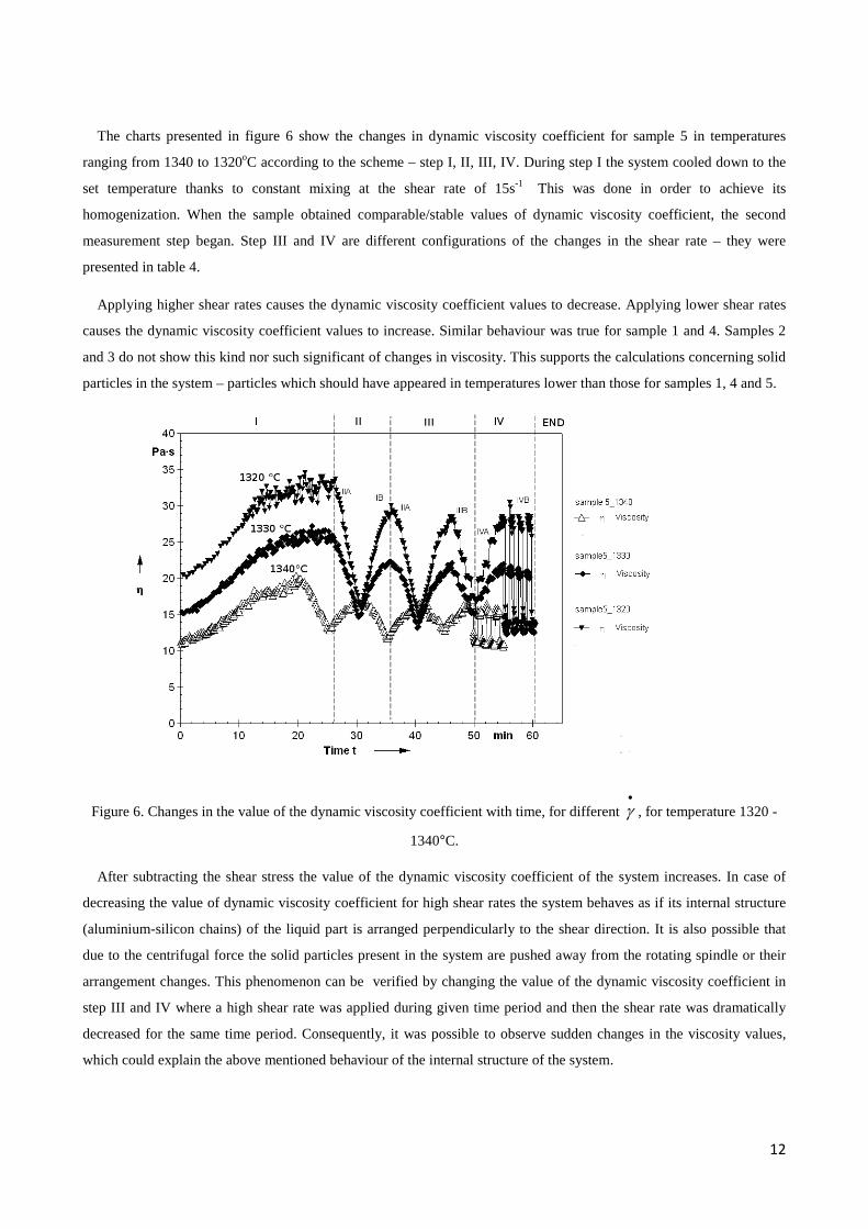
The charts presented in figure 6 show the changes in dynamic viscosity coefficient for sample 5 in temperatures
ranging from 1340 to 1320oC according to the scheme – step I, II, III, IV. During step I the system cooled down to the
set temperature thanks to constant mixing at the shear rate of 15s-1 This was done in order to achieve its
homogenization. When the sample obtained comparable/stable values of dynamic viscosity coefficient, the second
measurement step began. Step III and IV are different configurations of the changes in the shear rate – they were
presented in table 4.
Applying higher shear rates causes the dynamic viscosity coefficient values to decrease. Applying lower shear rates
causes the dynamic viscosity coefficient values to increase. Similar behaviour was true for sample 1 and 4. Samples 2
and 3 do not show this kind nor such significant of changes in viscosity. This supports the calculations concerning solid
particles in the system – particles which should have appeared in temperatures lower than those for samples 1, 4 and 5.
Figure 6. Changes in the value of the dynamic viscosity coefficient with time, for different •
γ , for temperature 1320 -
1340°C.
After subtracting the shear stress the value of the dynamic viscosity coefficient of the system increases. In case of
decreasing the value of dynamic viscosity coefficient for high shear rates the system behaves as if its internal structure
(aluminium-silicon chains) of the liquid part is arranged perpendicularly to the shear direction. It is also possible that
due to the centrifugal force the solid particles present in the system are pushed away from the rotating spindle or their
arrangement changes. This phenomenon can be verified by changing the value of the dynamic viscosity coefficient in
step III and IV where a high shear rate was applied during given time period and then the shear rate was dramatically
decreased for the same time period. Consequently, it was possible to observe sudden changes in the viscosity values,
which could explain the above mentioned behaviour of the internal structure of the system.
13
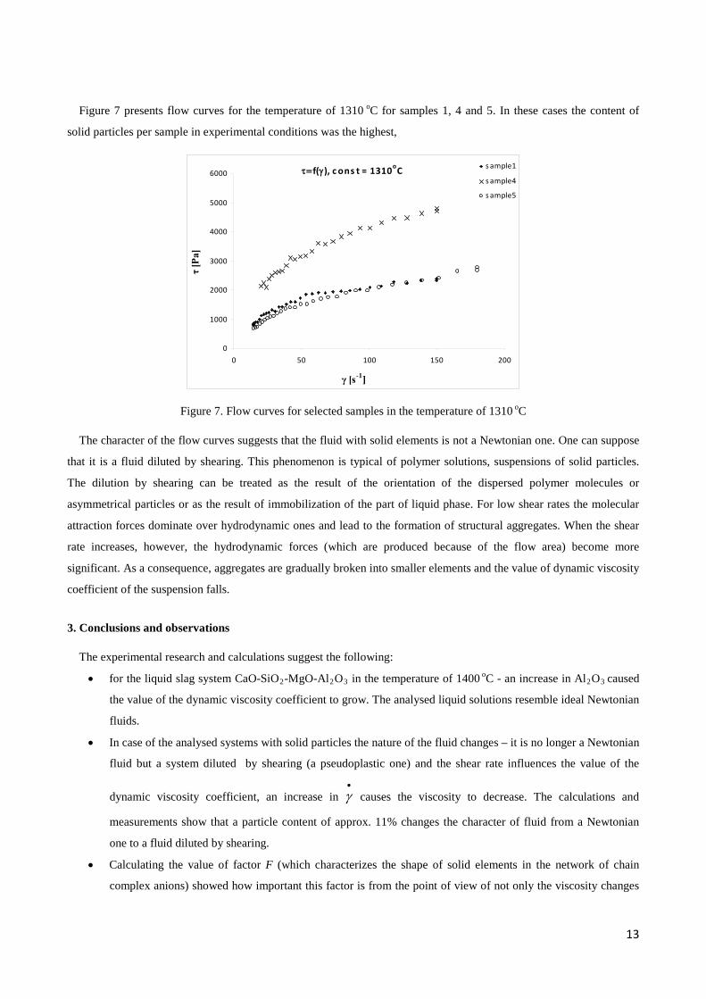
Figure 7 presents flow curves for the temperature of 1310 oC for samples 1, 4 and 5. In these cases the content of
solid particles per sample in experimental conditions was the highest,
τ=f(γ), c ons t = 1310oC
0
1000
2000
3000
4000
5000
6000
0 50 100 150 200
γ [s-1]
τ [P
a]
s ample1
s ample4
s ample5
Figure 7. Flow curves for selected samples in the temperature of 1310 oC
The character of the flow curves suggests that the fluid with solid elements is not a Newtonian one. One can suppose
that it is a fluid diluted by shearing. This phenomenon is typical of polymer solutions, suspensions of solid particles.
The dilution by shearing can be treated as the result of the orientation of the dispersed polymer molecules or
asymmetrical particles or as the result of immobilization of the part of liquid phase. For low shear rates the molecular
attraction forces dominate over hydrodynamic ones and lead to the formation of structural aggregates. When the shear
rate increases, however, the hydrodynamic forces (which are produced because of the flow area) become more
significant. As a consequence, aggregates are gradually broken into smaller elements and the value of dynamic viscosity
coefficient of the suspension falls.
3. Conclusions and observations
The experimental research and calculations suggest the following:
• for the liquid slag system CaO-SiO2-MgO-Al2O3 in the temperature of 1400 oC - an increase in Al2O3 caused
the value of the dynamic viscosity coefficient to grow. The analysed liquid solutions resemble ideal Newtonian
fluids.
• In case of the analysed systems with solid particles the nature of the fluid changes – it is no longer a Newtonian
fluid but a system diluted by shearing (a pseudoplastic one) and the shear rate influences the value of the
dynamic viscosity coefficient, an increase in •
γ causes the viscosity to decrease. The calculations and
measurements show that a particle content of approx. 11% changes the character of fluid from a Newtonian
one to a fluid diluted by shearing.
• Calculating the value of factor F (which characterizes the shape of solid elements in the network of chain
complex anions) showed how important this factor is from the point of view of not only the viscosity changes
14
but also the rheological character of the fluid. As far as solid-liquid slag systems are concerned, it seems vital
to take into consideration the shear rates by using Einstein’s equation.
• Adding Al2O3 to the slag systems causes the amount of solid particles to increase in higher temperatures. It
also leads to the polymerization of the viscous part of the system. The slag system changes its character from
Newtonian to pseudoplastic.
The question of the internal structure of the strongly polymerized slag systems with solid particles still remains open.
So does the influence of the applied shear stress on such a system – this in turn affects the dynamic viscosity coefficient
and potentially triggers changes in rheological character of the fluid. Further stages of research will focus on verifying
the influence of the shape and concentration of solid particles on the rheological character of slag and the value of the
viscosity coefficient.
4. Credits
These experiments and studies were conducted as part of a research project: „Developing an empirical model of the
rheological properties of liquid metals on the example of iron solutions” number 2011/01/N/ST8/07368 financed by the
National Science Centre.
References: [1] Y. Sasaki, H. Urata M. Iguchi and M. Hino. Stress Relaxation Behavior with Molten CaO–SiO2–Al2O3 Slag. ISIJ
International, vol. 46, 2006, nr 3, pp. 385–387. [2] S. Seetharaman K. Mukai, Du Sichen. Viscosity of slags – an overview. Steel Research Int., vol. 76, 2005, nr 4,
pp.267-278. [3] S. Seok, S. Jung, Y. Lee, D. Min. Viscosity of highly basic slags, ISIJ Int., vol.47, 2007, nr 8, pp.1090-1096. [4] N. N. Viswanathan, F.-Z. Ji, Du Sichen and S. Seetharaman. Viscosity Measurements on Some Fayalite Slags. ISIJ
International, vol. 41, 2001,nr 7, pp. 722–727. [5] A. Shankar, M. Görnerup, A.K. Lahiri, and S. Seetharaman. Experimental Investigation of the Viscosities in CaO-
SiO2-MgO-Al2O3 and CaO-SiO2-MgO-Al2O3-TiO2 Slags. Metallurgical and Mat. Trans. B, vol. 38B, 2007, nr12, p. 911.
[6] A. Kondratiev, B. Zhao, S. Raghunath, P.C. Hayes and E. Jak. New tools for viscosity measurement and modeling of fully liquid and partly crystallised slags; Proceedings of EMC 2007.
[7] S. Wright, L. Zhang, S. Sun, S. Jahanshahi. Viscosity of a CaO-MgO-Al2O3-SiO2 Melt Containing Spinel Particles at 1646K. Metallurgical and Mat. Trans. B, vol. 31B, 2000, nr 2, pp. 97-104.
[8] A. Kondratiev, P. C. Hayes and E. Jak. Development of a Quasi-chemical Viscosity Model for Fully Liquid Slags in the Al2O3–CaO–‘FeO’–MgO–SiO2 System. Part 1. Description of the Model and Its Application to the MgO, MgO–SiO2, Al2O3–MgO and CaO–MgO Sub-systems. ISIJ International, Vol. 46 (2006), No. 3, pp. 359–367.
[9] A. Kondratiev, P. C. Hayes and E. Jak. Development of a Quasi-chemical Viscosity Model for Fully Liquid Slags in the Al2O3–CaO–‘FeO’–MgO–SiO2 System. Part 2. A Review of the Experimental Data and the Model Predictions for the Al2O3–CaO-MgO, CaO–MgO–SiO2 and Al2O3–MgO–SiO2 Systems. ISIJ International, Vol. 46 (2006), No. 3, pp. 368–374.
15
[10] A. Kondratiev, P. C. Hayes and E. Jak. Development of a Quasi-chemical Viscosity Model for Fully Liquid Slags in the Al2O3–CaO–‘FeO’–MgO–SiO2 System. Part 3. Summary of the Model Predictions for the Al2O3–CaO–MgO–SiO2 System and Its Sub-systems. ISIJ International, Vol. 46 (2006), No. 3, pp. 375–384.
[11] A. Kondratiev, P. C. Hayes and E. Jak. Development of a Quasi-chemical Viscosity Model for Fully Liquid Slags in the Al2O3–CaO–‘FeO’–MgO–SiO2 System. The Experimental Data for the ‘FeO’–MgO–SiO2, CaO–‘FeO’–MgO–SiO2 and Al2O3–CaO–‘FeO’–MgO–SiO2 Systems at Iron Saturation. ISIJ International, Vol. 48 (2008), No. 1, pp. 7–16.
[12] A. Kondratiev, E. Jak. Review of Experimental Data and Modeling of the Viscosities of Fully Liquid Slags in the Al2O3-CaO-‘FeO’-SiO2 System. Metallurgical And Materials Transactions B Volume 32b, December 2001, 1015.
[13] K.C. Mills and S. Sridhar. Ironmaking & Steelmaking, 1999, vol. 26, pp. 262-268. [14] J. Ferguson, Z. Kembłowski. Reologia stosowana płynów. Wydawnictwo MARCUS, Łódź, 1995. [15] G. Handfield, G.G. Charette G.G. Viscosity and structure of industrial high TiO2 slags. Canadian Metallurgical
Quarterly, vol. 10, nr 3, 1971. [16] G. Handfield, G.G. Charette G.G., Lee H.Y. Titanium bearing ore and blast furnace slag viscosity. Journal of
Metals, September ,1972. [17] G. Handfield, G.G. Charette G.G., Lee H.Y. Viscosity of industrial titania slags. Light Metals 1971, Aluminum
Company of Canada, Montreal, Canada, Proceedings of Symposia, 100th AIME Annual Meeting, New York, March 1-4, 1971.
[18] D. Xie, Y. Mao AND Y. Zhu. Viscosity and flow behaviour of TiO2-containing blast furnace slags under reducing conditions. VII International Conference on Molten Slags Fluxes and Salts, The South African Institute of Mining and Metallurgy, 2004.
[19] M. Song, Q. Shu, and Du Sichen. Viscosities of the Quaternary Al2O3-CaO-MgO-SiO2 Slags. Steel Research Int. 82 (2011) No. 3,
[20] K.Mills. The estimation of slag properties. Department of Materials, Imperial College, London, UK, Short course presented as part of Southern African Pyrometallurgy 2011,
[21] A.R. Boccaccini, S. Riazc, C. Moisescu. On the viscosity of glass-crystal systems. Journal Of Materials Science LETTERS 20, 2001, 1803 – 1805.
[22] G. Schramm. Reologia- Podstawy i zastosowania, Haake GmbH, OWN PAN, Poznań 1998,