rgb 202 rxi , rgb 202 rxi vtg - extron electronics · rgb 202 rxi, rgb 202 rxi vtg. precautions...
TRANSCRIPT
User’s Manual
Extron Electronics, USA1230 South Lewis StreetAnaheim, CA 92805USA714.491.1500 Fax 714.491.1517
Extron Electronics, EuropeBeeldschermweg 6C3821 AH AmersfoortThe Netherlands+31.33.453.4040 Fax +31.33.453.4050
Extron Electronics, Asia135 Joo Seng Road, #04-01PM Industrial BuildingSingapore 368363+65.6383.4400 Fax +65.6383.4664
Extron Electronics, JapanDaisan DMJ Building 6F3-9-1 Kudan MinamiChiyoda-ku, Tokyo 102-0074 Japan +81.3.3511.7655 Fax +81.3.3511.7656www.extron.com
© 2002 Extron Electronics. All rights reserved.
Universal Interfaces with Stereo Audio and ADSP™
68-500-01Printed in the USA
RGB 202 Rxixixixixi , RGB 202 Rxixixixixi VTG
Precautions
This symbol is intended to alert the user of importantoperating and maintenance (servicing) instructionsin the literature provided with the equipment.
This symbol is intended to alert the user of thepresence of uninsulated dangerous voltage withinthe product's enclosure that may present a risk ofelectric shock.
CautionRead Instructions • Read and understand all safety and operating
instructions before using the equipment.Retain Instructions • The safety instructions should be kept for future
reference.Follow Warnings • Follow all warnings and instructions marked on the
equipment or in the user information.Avoid Attachments • Do not use tools or attachments that are not
recommended by the equipment manufacturer because they may behazardous.
WarningPower sources • This equipment should be operated only from the power source
indicated on the product. This equipment is intended to be used with a mainpower system with a grounded (neutral) conductor. The third (grounding) pin isa safety feature, do not attempt to bypass or disable it.
Power disconnection • To remove power from the equipment safely, remove allpower cords from the rear of the equipment, or the desktop power module (ifdetachable), or from the power source receptacle (wall plug).
Power cord protection • Power cords should be routed so that they are not likely tobe stepped on or pinched by items placed upon or against them.
Servicing • Refer all servicing to qualified service personnel. There are no user-serviceable parts inside. To prevent the risk of shock, do not attempt to servicethis equipment yourself because opening or removing covers may expose you todangerous voltage or other hazards.
Slots and openings • If the equipment has slots or holes in the enclosure, these areprovided to prevent overheating of sensitive components inside. These openingsmust never be blocked by other objects.
Lithium battery • There is a danger of explosion if battery is incorrectly replaced.Replace it only with the same or equivalent type recommended by themanufacturer. Dispose of used batteries according to the manufacturer'sinstructions.
Ce symbole sert à avertir l’utilisateur que ladocumentation fournie avec le matériel contient desinstructions importantes concernant l’exploitationet la maintenance (réparation).
Ce symbole sert à avertir l’utilisateur de la présencedans le boîtier de l’appareil de tensions dangereusesnon isolées posant des risques d’électrocution.
AttentionLire les instructions• Prendre connaissance de toutes les consignes de
sécurité et d’exploitation avant d’utiliser le matériel.Conserver les instructions• Ranger les consignes de sécurité afin de
pouvoir les consulter à l’avenir.Respecter les avertissements • Observer tous les avertissements et
consignes marqués sur le matériel ou présentés dans la documentationutilisateur.
Eviter les pièces de fixation • Ne pas utiliser de pièces de fixation nid’outils non recommandés par le fabricant du matériel car celarisquerait de poser certains dangers.
AvertissementAlimentations• Ne faire fonctionner ce matériel qu’avec la source d’alimentation
indiquée sur l’appareil. Ce matériel doit être utilisé avec une alimentationprincipale comportant un fil de terre (neutre). Le troisième contact (de mise à laterre) constitue un dispositif de sécurité : n’essayez pas de la contourner ni de ladésactiver.
Déconnexion de l’alimentation• Pour mettre le matériel hors tension sans danger,déconnectez tous les cordons d’alimentation de l’arrière de l’appareil ou dumodule d’alimentation de bureau (s’il est amovible) ou encore de la prise secteur.
Protection du cordon d’alimentation • Acheminer les cordons d’alimentation demanière à ce que personne ne risque de marcher dessus et à ce qu’ils ne soientpas écrasés ou pincés par des objets.
Réparation-maintenance • Faire exécuter toutes les interventions de réparation-maintenance par un technicien qualifié. Aucun des éléments internes ne peut êtreréparé par l’utilisateur. Afin d’éviter tout danger d’électrocution, l’utilisateur nedoit pas essayer de procéder lui-même à ces opérations car l’ouverture ou leretrait des couvercles risquent de l’exposer à de hautes tensions et autres dangers.
Fentes et orifices • Si le boîtier de l’appareil comporte des fentes ou des orifices,ceux-ci servent à empêcher les composants internes sensibles de surchauffer. Cesouvertures ne doivent jamais être bloquées par des objets.
Lithium Batterie • Il a danger d'explosion s'll y a remplacment incorrect de labatterie. Remplacer uniquement avec une batterie du meme type ou d'un ypeequivalent recommande par le constructeur. Mettre au reut les batteries usageesconformement aux instructions du fabricant.
Safety Instructions • English
Consignes de Sécurité • Français
Sicherheitsanleitungen • DeutschDieses Symbol soll dem Benutzer in der imLieferumfang enthaltenen Dokumentationbesonders wichtige Hinweise zur Bedienung undWartung (Instandhaltung) geben.
Dieses Symbol soll den Benutzer darauf aufmerksammachen, daß im Inneren des Gehäuses diesesProduktes gefährliche Spannungen, die nicht isoliertsind und die einen elektrischen Schock verursachenkönnen, herrschen.
AchtungLesen der Anleitungen • Bevor Sie das Gerät zum ersten Mal verwenden,
sollten Sie alle Sicherheits-und Bedienungsanleitungen genaudurchlesen und verstehen.
Aufbewahren der Anleitungen • Die Hinweise zur elektrischen Sicherheitdes Produktes sollten Sie aufbewahren, damit Sie im Bedarfsfall daraufzurückgreifen können.
Befolgen der Warnhinweise • Befolgen Sie alle Warnhinweise undAnleitungen auf dem Gerät oder in der Benutzerdokumentation.
Keine Zusatzgeräte • Verwenden Sie keine Werkzeuge oder Zusatzgeräte,die nicht ausdrücklich vom Hersteller empfohlen wurden, da diese eineGefahrenquelle darstellen können.
VorsichtStromquellen • Dieses Gerät sollte nur über die auf dem Produkt angegebene
Stromquelle betrieben werden. Dieses Gerät wurde für eine Verwendung miteiner Hauptstromleitung mit einem geerdeten (neutralen) Leiter konzipiert. Derdritte Kontakt ist für einen Erdanschluß, und stellt eine Sicherheitsfunktion dar.Diese sollte nicht umgangen oder außer Betrieb gesetzt werden.
Stromunterbrechung • Um das Gerät auf sichere Weise vom Netz zu trennen,sollten Sie alle Netzkabel aus der Rückseite des Gerätes, aus der externenStomversorgung (falls dies möglich ist) oder aus der Wandsteckdose ziehen.
Schutz des Netzkabels • Netzkabel sollten stets so verlegt werden, daß sie nichtim Weg liegen und niemand darauf treten kann oder Objekte darauf- oderunmittelbar dagegengestellt werden können.
Wartung • Alle Wartungsmaßnahmen sollten nur von qualifiziertemServicepersonal durchgeführt werden. Die internen Komponenten des Gerätessind wartungsfrei. Zur Vermeidung eines elektrischen Schocks versuchen Sie inkeinem Fall, dieses Gerät selbst öffnen, da beim Entfernen der Abdeckungen dieGefahr eines elektrischen Schlags und/oder andere Gefahren bestehen.
Schlitze und Öffnungen • Wenn das Gerät Schlitze oder Löcher im Gehäuseaufweist, dienen diese zur Vermeidung einer Überhitzung der empfindlichenTeile im Inneren. Diese Öffnungen dürfen niemals von anderen Objektenblockiert werden.
Litium-Batterie • Explosionsgefahr, falls die Batterie nicht richtig ersetzt wird.Ersetzen Sie verbrauchte Batterien nur durch den gleichen oder einenvergleichbaren Batterietyp, der auch vom Hersteller empfohlen wird. EntsorgenSie verbrauchte Batterien bitte gemäß den Herstelleranweisungen.
Este símbolo se utiliza para advertir al usuario sobreinstrucciones importantes de operación ymantenimiento (o cambio de partes) que se deseandestacar en el contenido de la documentaciónsuministrada con los equipos.
Este símbolo se utiliza para advertir al usuario sobrela presencia de elementos con voltaje peligroso sinprotección aislante, que puedan encontrarse dentrode la caja o alojamiento del producto, y que puedanrepresentar riesgo de electrocución.
PrecaucionLeer las instrucciones • Leer y analizar todas las instrucciones de
operación y seguridad, antes de usar el equipo.Conservar las instrucciones • Conservar las instrucciones de seguridad
para futura consulta.Obedecer las advertencias • Todas las advertencias e instrucciones
marcadas en el equipo o en la documentación del usuario, deben serobedecidas.
Evitar el uso de accesorios • No usar herramientas o accesorios que nosean especificamente recomendados por el fabricante, ya que podrianimplicar riesgos.
AdvertenciaAlimentación eléctrica • Este equipo debe conectarse únicamente a la fuente/tipo
de alimentación eléctrica indicada en el mismo. La alimentación eléctrica de esteequipo debe provenir de un sistema de distribución general con conductorneutro a tierra. La tercera pata (puesta a tierra) es una medida de seguridad, nopuentearia ni eliminaria.
Desconexión de alimentación eléctrica • Para desconectar con seguridad laacometida de alimentación eléctrica al equipo, desenchufar todos los cables dealimentación en el panel trasero del equipo, o desenchufar el módulo dealimentación (si fuera independiente), o desenchufar el cable del receptáculo dela pared.
Protección del cables de alimentación • Los cables de alimentación eléctrica sedeben instalar en lugares donde no sean pisados ni apretados por objetos que sepuedan apoyar sobre ellos.
Reparaciones/mantenimiento • Solicitar siempre los servicios técnicos de personalcalificado. En el interior no hay partes a las que el usuario deba acceder. Paraevitar riesgo de electrocución, no intentar personalmente la reparación/mantenimiento de este equipo, ya que al abrir o extraer las tapas puede quedarexpuesto a voltajes peligrosos u otros riesgos.
Ranuras y aberturas • Si el equipo posee ranuras o orificios en su caja/alojamiento,es para evitar el sobrecalientamiento de componentes internos sensibles. Estasaberturas nunca se deben obstruir con otros objetos.
Batería de litio • Existe riesgo de explosión si esta batería se coloca en la posiciónincorrecta. Cambiar esta batería únicamente con el mismo tipo (o su equivalente)recomendado por el fabricante. Desachar las baterías usadas siguiendo lasinstrucciones del fabricante.
Instrucciones de seguridad • Español
FCC Class A NoticeNote: This equipment has been tested and found to comply with the limits for aClass A digital device, pursuant to part 15 of the FCC Rules. These limits are designedto provide reasonable protection against harmful interference when the equipment isoperated in a commercial environment. This equipment generates, uses and canradiate radio frequency energy and, if not installed and used in accordance with theinstruction manual, may cause harmful interference to radio communications.Operation of this equipment in a residential area is likely to cause harmfulinterference, in which case the user will be required to correct the interference at hisown expense.
Note: This unit was tested with shielded cables on the peripheral devices. Shieldedcables must be used with the unit to ensure compliance.
Extron’s WarrantyExtron Electronics warrants this product against defects in materials andworkmanship for a period of three years from the date of purchase. In the event ofmalfunction during the warranty period attributable directly to faulty workmanshipand/or materials, Extron Electronics will, at its option, repair or replace said productsor components, to whatever extent it shall deem necessary to restore said product toproper operating condition, provided that it is returned within the warranty period,with proof of purchase and description of malfunction to:
USA, Canada, Europe, Africa, andSouth America, and the Middle East: Asia:Central America:
Extron Electronics, Europe Extron Electronics, AsiaExtron Electronics Beeldschermweg 6C 135 Joo Seng Road, #04-011230 South Lewis Street 3821 AH Amersfoort PM Industrial Bldg.Anaheim, CA 92805, USA The Netherlands Singapore 368363
This Limited Warranty does not apply if the fault has been caused by misuse,improper handling care, electrical or mechanical abuse, abnormal operating conditionsor non-Extron authorized modification to the product.
If it has been determined that the product is defective, please call Extron and ask for anApplications Engineer at (714) 491-1500 (USA), 31.33.453.4040 (Europe), or 65.6383.4400(Asia) to receive an RA# (Return Authorization number). This will begin the repairprocess as quickly as possible.
Units must be returned insured, with shipping charges prepaid. If not insured, youassume the risk of loss or damage during shipment. Returned units must include theserial number and a description of the problem, as well as the name of the person tocontact in case there are any questions.
Extron Electronics makes no further warranties either expressed or implied withrespect to the product and its quality, performance, merchantability, or fitness for anyparticular use. In no event will Extron Electronics be liable for direct, indirect, orconsequential damages resulting from any defect in this product even if ExtronElectronics has been advised of such damage.
Please note that laws vary from state to state and country to country, and that someprovisions of this warranty may not apply to you.
iRGB 202 Rxxxxxiiiii, RGB 202 Rxxxxxiiiii VTG • Table of Contents
Chapter 1 • Introduction .......................................................... 1-1
About this Manual ................................................................ 1-2
About the RGB 202 Rxxxxxiiiii and RGB 202 Rxxxxxiiiii VTG ............ 1-2
Features ...................................................................................... 1-2Features of both models ....................................................... 1-2Additional RGB 202 Rxi VTG feature .................................... 1-4
Chapter 2 • Installation and Operation ......................... 2-1
Installation and Operation Overview ......................... 2-2
Mounting the Interfaces .................................................... 2-2Tabletop/desktop placement ................................................ 2-3Under-desk mounting ........................................................... 2-3Through-desk mounting ....................................................... 2-4Rack mounting ....................................................................... 2-5
Front Panel ................................................................................ 2-6
Rear Panel .................................................................................. 2-9
Cabling ...................................................................................... 2-11
LCD Display ............................................................................. 2-14LCD screen backlight ........................................................... 2-14Scan rate indication ............................................................. 2-14Centering ............................................................................. 2-14
Operating the VTG (RGB 202 Rxixixixixi VTG only) ............ 2-15
Troubleshooting ................................................................... 2-16
Chapter 3 • Remote Control .................................................. 3-1
RS-232 Programmer’s Guide ............................................ 3-2Host-to-interface communications ....................................... 3-2Interface-initiated messages ................................................. 3-2Error responses ...................................................................... 3-3Using the command/response table ..................................... 3-3Command/response table ..................................................... 3-4
Control Software for Windows ...................................... 3-5Installing the software .......................................................... 3-5Using the software ................................................................ 3-5
Contact Closure Remote Control ................................... 3-6
Table of Contents
ii RGB 202 Rxxxxxiiiii, RGB 202 Rxxxxxiiiii VTG • Table of Contents
Table of Contents, cont’d
RGB 202 Rxxxxxiiiii, RGB 202 Rxxxxxiiiii VTG
1Chapter One
Introduction
About this Manual
About the RGB 202 Rxi and RGB 202 Rxi VTG
Features
Appendix • Specifications, Accessories andPart Numbers ................................................................................... A-1
Specifications ......................................................................... A-2
Included Parts ......................................................................... A-5
Optional Accessories ........................................................... A-5
Cables ......................................................................................... A-5
68-500-01 Rev. CPrinted in the USA
03 02
RGB 202 Rxxxxxiiiii, RGB 202 Rxxxxxiiiii VTG • IntroductionRGB 202 Rxxxxxiiiii, RGB 202 Rxxxxxiiiii VTG • Introduction
Introduction, cont’d
Thirty memory presets — Thirty spaces are reserved in theinterface’s memory for storing user-defined combinationsof horizontal and vertical position settings based uponinput signal scan rates. The interface automaticallyrecalls the position settings when it detects an inputsignal with a matching scan rate.
LCD scan rate indicator — This backlit liquid crystal display(LCD) indicates the horizontal and vertical sync rates, andthe minimum and maximum centering limits. A DIPswitch is provided for turning off the backlight.
MBC power jacks — These jacks provide power to bufferedmonitor breakout cables.
75 ohm video termination switches — Rear panel DIP switchesprovide a way to switch between high Z and 75 ohmvideo input termination for systems where a localcomputer monitor is not used.
RGBHV, RGBS, or RGsB outputs — Select the output formatvia cabling setup and rear panel DIP switch.
Serration pulse switch — This DIP switch-selectable featureadds or strips the serration pulses from the output signalto make it compatible with digital display devices. Usethe serration pulse switch if flagging or bending occurs atthe top of the video display.
Sync polarity adjustment — Horizontal and vertical syncoutput can either follow input sync polarity, or outgoingsync can be forced to negative via a rear panel DIP switch.
Vertical sync pulse width adjustment — Vertical sync pulsewidth can be adjusted via a rear panel DIP switch.
Remote control input selection — Connect a remote contactclosure keypad, an RS-232 control system, or a computerto the rear panel RS-232 port to remotely control theinterface.
Vented metal enclosure — Vents in the enclosure keep theinterface cool and ready for use 24 hours a day, 7 days perweek.
Automatic sync stripping — Sync signals are automaticallystripped from the red, green and blue video input signals.The interfaces output sync simultaneously as separatehorizontal and vertical sync and as composite sync, butsync on green (SOG) can be selected via a rear panel DIPswitch.
Introduction
About this ManualThis manual contains information about the ExtronRGB 202 Rxi and RGB 202 Rxi VTG universal interfaces and onhow to operate and configure them.
About the RGB 202 Rxixixixixi and RGB 202 Rxixixixixi VTGThe RGB 202 Rxi is an analog computer-video interface with300 MHz (-3dB) video bandwidth and Advanced Digital SyncProcessing™. It accepts two computer-video and twounbalanced computer stereo audio inputs. It also features oneRGBHV, RGBS or RGsB output and one balanced, line levelstereo audio output. The RGB 202 Rxi VTG is identical to theRGB 202 Rxi except that it also contains a built-in video testgenerator (VTG).
Front panel controls, remote contact closure, or an RS-232remote control system or computer can be used to selectbetween inputs.
Features
Features of both modelsFlexible mounting options — The RGB 202 Rxi and
RGB 202 Rxi VTG can be rack mounted, mounted under adesk or podium, or mounted through a desk or otherfurniture with optional mounting kits.
Stereo audio — Unbalanced PC stereo audio inputs are outputas line level, balanced stereo audio.
Level (boost) and peaking controls — Separate front panelcontrols compensate for signal losses from long cableruns.
Horizontal and vertical centering controls — These front panelcontrols allow separate horizontal and vertical centeringadjustments.
Digital sync processing — Using regular sync processing toallow centering control (H-shift or V-shift) can createproblems with some digital display devices as a result ofthe sync delay. Extron’s ADSP™ (Advanced Digital SyncProcessing™) maintains a stable sync signal whileallowing centering control. These interfaces also provideanother option, DDSP™ (Digital Display SyncProcessing™), to ensure proper displays without alteringsync pulse timing or width. The sync processing type isselected via a rear panel DIP switch.
1-2 1-3
RGB 202 Rxxxxxiiiii, RGB 202 Rxxxxxiiiii VTG • Introduction
Introduction, cont’d
RGB 202 Rxxxxxiiiii, RGB 202 Rxxxxxiiiii VTG
2Chapter Two
Installation and Operation
Installation and Operation Overview
Mounting the Interfaces
Front Panel
Rear Panel
Cabling
LCD Display
Operating the VTG (RGB 202 Rxi VTG only)
Troubleshooting
Additional RGB 202 Rxixixixixi VTG featureVideo test generator — The RGB 202 Rxi VTG includes a
4-resolution, 4-pattern video test generator to simplifysystem setup and testing.
1-4
RGB 202 Rxxxxxiiiii, RGB 202 Rxxxxxiiiii VTG • Installation and OperationRGB 202 Rxxxxxiiiii, RGB 202 Rxxxxxiiiii VTG • Installation and Operation
Installation and Operation, cont’d
2-3
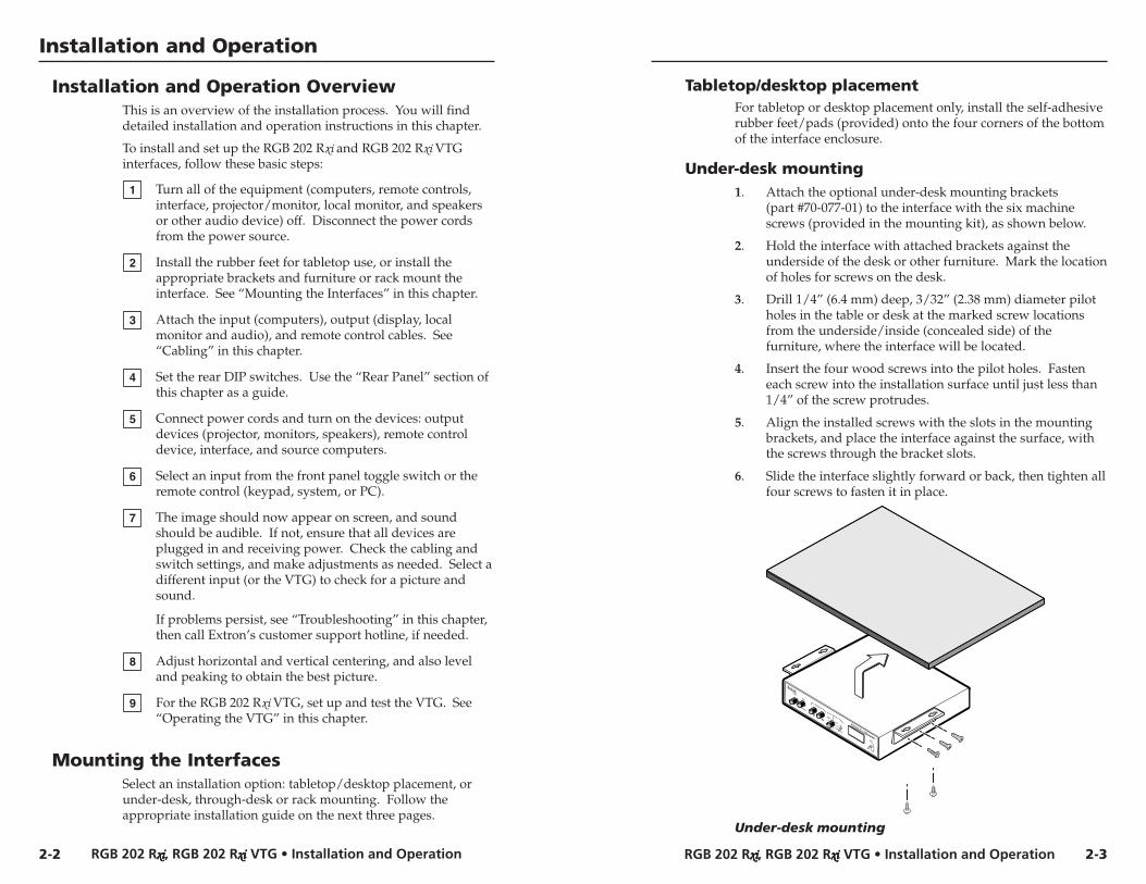
Tabletop/desktop placementFor tabletop or desktop placement only, install the self-adhesiverubber feet/pads (provided) onto the four corners of the bottomof the interface enclosure.
Under-desk mounting1. Attach the optional under-desk mounting brackets
(part #70-077-01) to the interface with the six machinescrews (provided in the mounting kit), as shown below.
2. Hold the interface with attached brackets against theunderside of the desk or other furniture. Mark the locationof holes for screws on the desk.
3. Drill 1/4” (6.4 mm) deep, 3/32” (2.38 mm) diameter pilotholes in the table or desk at the marked screw locationsfrom the underside/inside (concealed side) of thefurniture, where the interface will be located.
4. Insert the four wood screws into the pilot holes. Fasteneach screw into the installation surface until just less than1/4” of the screw protrudes.
5. Align the installed screws with the slots in the mountingbrackets, and place the interface against the surface, withthe screws through the bracket slots.
6. Slide the interface slightly forward or back, then tighten allfour screws to fasten it in place.
RGB 202 RVTG
BOOST
LEVEL
CONTROL
PEAK
INPUT1
2
WITH ADSP TM
MINI VTG
CENTERING
SXGA
SVGA
VGA
202
VTG
XGA
Under-desk mounting
Installation and Operation
Installation and Operation OverviewThis is an overview of the installation process. You will finddetailed installation and operation instructions in this chapter.
To install and set up the RGB 202 Rxi and RGB 202 Rxi VTGinterfaces, follow these basic steps:
1 Turn all of the equipment (computers, remote controls,interface, projector/monitor, local monitor, and speakersor other audio device) off. Disconnect the power cordsfrom the power source.
2 Install the rubber feet for tabletop use, or install theappropriate brackets and furniture or rack mount theinterface. See “Mounting the Interfaces” in this chapter.
3 Attach the input (computers), output (display, localmonitor and audio), and remote control cables. See“Cabling” in this chapter.
4 Set the rear DIP switches. Use the “Rear Panel” section ofthis chapter as a guide.
5 Connect power cords and turn on the devices: outputdevices (projector, monitors, speakers), remote controldevice, interface, and source computers.
6 Select an input from the front panel toggle switch or theremote control (keypad, system, or PC).
7 The image should now appear on screen, and soundshould be audible. If not, ensure that all devices areplugged in and receiving power. Check the cabling andswitch settings, and make adjustments as needed. Select adifferent input (or the VTG) to check for a picture andsound.
If problems persist, see “Troubleshooting” in this chapter,then call Extron’s customer support hotline, if needed.
8 Adjust horizontal and vertical centering, and also leveland peaking to obtain the best picture.
9 For the RGB 202 Rxi VTG, set up and test the VTG. See“Operating the VTG” in this chapter.
2-2
Mounting the InterfacesSelect an installation option: tabletop/desktop placement, orunder-desk, through-desk or rack mounting. Follow theappropriate installation guide on the next three pages.
RGB 202 Rxxxxxiiiii, RGB 202 Rxxxxxiiiii VTG • Installation and OperationRGB 202 Rxxxxxiiiii, RGB 202 Rxxxxxiiiii VTG • Installation and Operation
Installation and Operation, cont’d
RGB 202
VTG
BOOST
LEVEL
CONTROL
PEAK
INPUT1
2
WITH ADSP TM
MINI VTG
CENTERING
Rxi
SXGASVGA
VGA
202
VTG
XGA
2-52-4
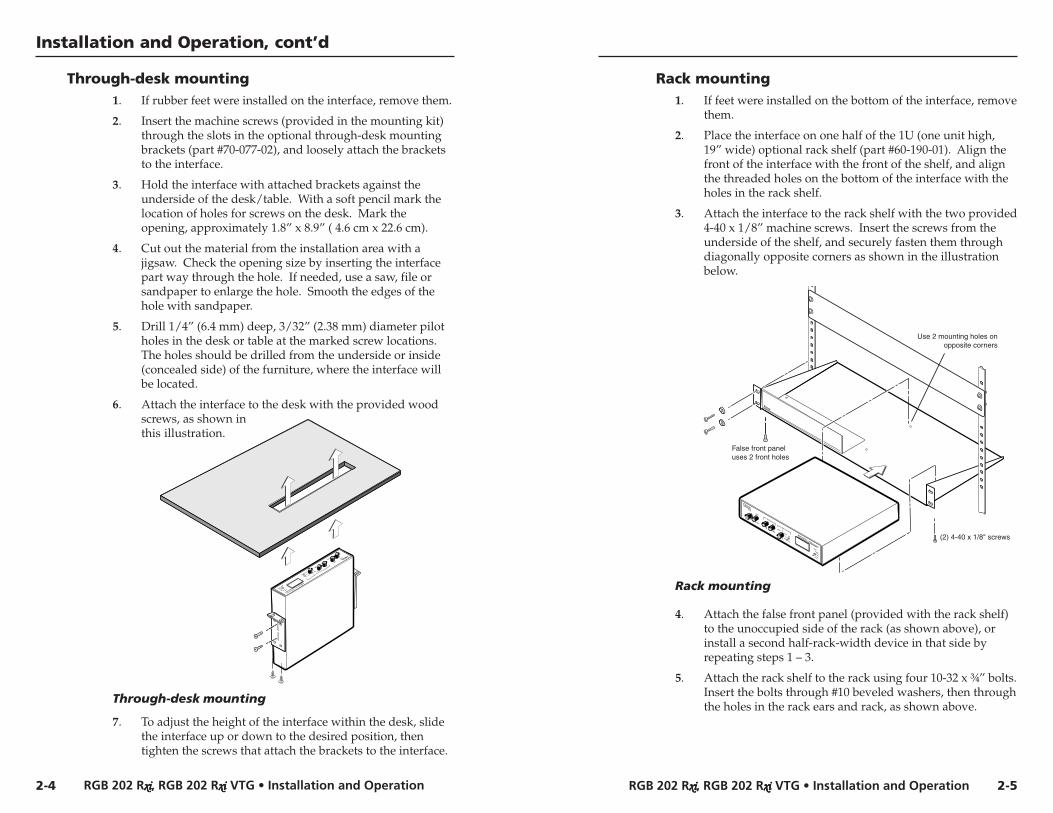
Through-desk mounting1. If rubber feet were installed on the interface, remove them.
2. Insert the machine screws (provided in the mounting kit)through the slots in the optional through-desk mountingbrackets (part #70-077-02), and loosely attach the bracketsto the interface.
3. Hold the interface with attached brackets against theunderside of the desk/table. With a soft pencil mark thelocation of holes for screws on the desk. Mark theopening, approximately 1.8” x 8.9” ( 4.6 cm x 22.6 cm).
4. Cut out the material from the installation area with ajigsaw. Check the opening size by inserting the interfacepart way through the hole. If needed, use a saw, file orsandpaper to enlarge the hole. Smooth the edges of thehole with sandpaper.
5. Drill 1/4” (6.4 mm) deep, 3/32” (2.38 mm) diameter pilotholes in the desk or table at the marked screw locations.The holes should be drilled from the underside or inside(concealed side) of the furniture, where the interface willbe located.
6. Attach the interface to the desk with the provided woodscrews, as shown inthis illustration.
Through-desk mounting
7. To adjust the height of the interface within the desk, slidethe interface up or down to the desired position, thentighten the screws that attach the brackets to the interface.
Rack mounting1. If feet were installed on the bottom of the interface, remove
them.
2. Place the interface on one half of the 1U (one unit high,19” wide) optional rack shelf (part #60-190-01). Align thefront of the interface with the front of the shelf, and alignthe threaded holes on the bottom of the interface with theholes in the rack shelf.
3. Attach the interface to the rack shelf with the two provided4-40 x 1/8” machine screws. Insert the screws from theunderside of the shelf, and securely fasten them throughdiagonally opposite corners as shown in the illustrationbelow.
(2) 4-40 x 1/8" screws
Use 2 mounting holes onopposite corners
False front paneluses 2 front holes
RGB 202 RVTG
BOOST
LEVEL
CONTROL
PEAK
INPUT1
2
WITH ADSP TM
MINI VTG
CENTERING
xi
SXGA
SVGA
VGA
202
VTG
XGA
Rack mounting
4. Attach the false front panel (provided with the rack shelf)to the unoccupied side of the rack (as shown above), orinstall a second half-rack-width device in that side byrepeating steps 1 – 3.
5. Attach the rack shelf to the rack using four 10-32 x ¾” bolts.Insert the bolts through #10 beveled washers, then throughthe holes in the rack ears and rack, as shown above.
RGB 202 Rxxxxxiiiii, RGB 202 Rxxxxxiiiii VTG • Installation and OperationRGB 202 Rxxxxxiiiii, RGB 202 Rxxxxxiiiii VTG • Installation and Operation
Installation and Operation, cont’d
2-6
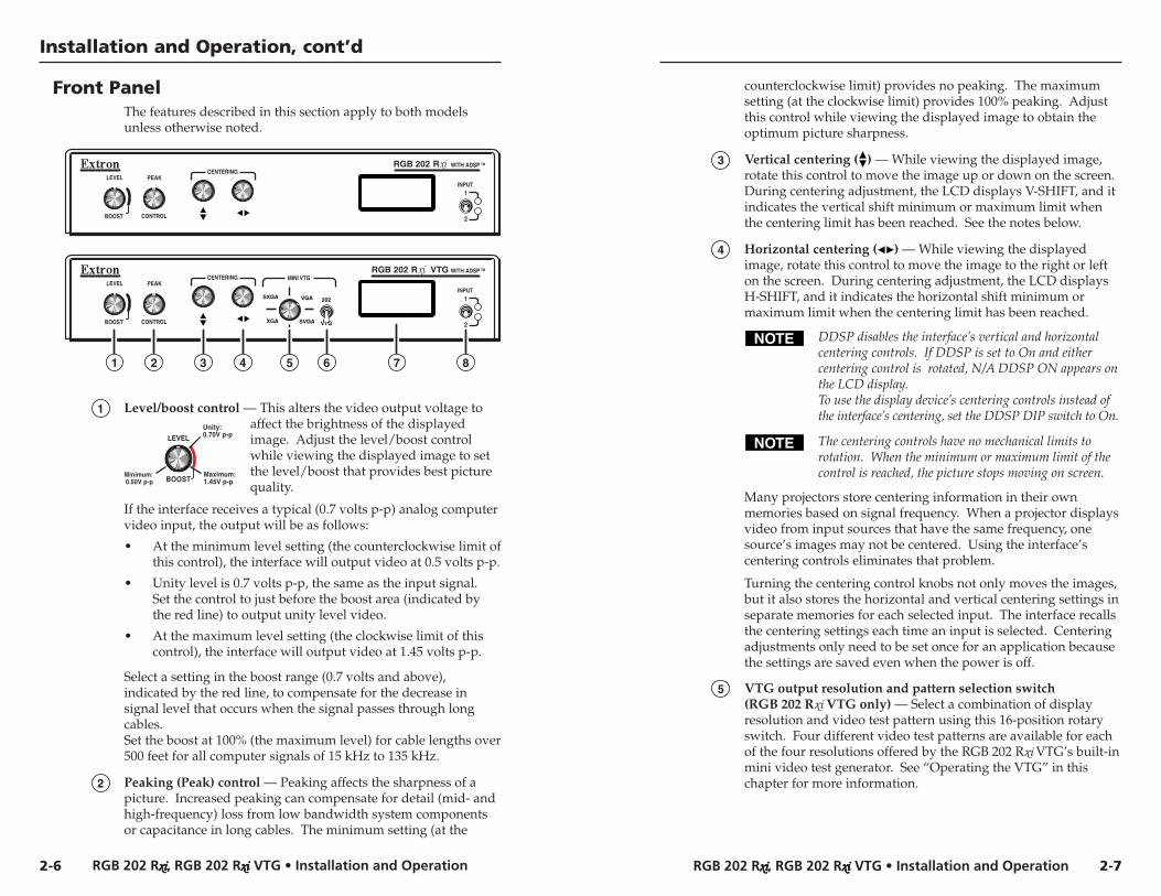
Front PanelThe features described in this section apply to both modelsunless otherwise noted.
RGB 202 R
BOOST
LEVEL
CONTROL
PEAKINPUT
1
2
WITH ADSP TM
CENTERING
RGB 202 R VTG
BOOST
LEVEL
CONTROL
PEAKINPUT
1
2
WITH ADSP TM
MINI VTGCENTERING
SXGA
SVGA
VGA 202
VTGXGA
1 2 3 4 6 7 85
counterclockwise limit) provides no peaking. The maximumsetting (at the clockwise limit) provides 100% peaking. Adjustthis control while viewing the displayed image to obtain theoptimum picture sharpness.
3 Vertical centering ( ) — While viewing the displayed image,rotate this control to move the image up or down on the screen.During centering adjustment, the LCD displays V-SHIFT, and itindicates the vertical shift minimum or maximum limit whenthe centering limit has been reached. See the notes below.
4 Horizontal centering ( ) — While viewing the displayedimage, rotate this control to move the image to the right or lefton the screen. During centering adjustment, the LCD displaysH-SHIFT, and it indicates the horizontal shift minimum ormaximum limit when the centering limit has been reached.
DDSP disables the interface’s vertical and horizontalcentering controls. If DDSP is set to On and eithercentering control is rotated, N/A DDSP ON appears onthe LCD display.To use the display device’s centering controls instead ofthe interface’s centering, set the DDSP DIP switch to On.
The centering controls have no mechanical limits torotation. When the minimum or maximum limit of thecontrol is reached, the picture stops moving on screen.
Many projectors store centering information in their ownmemories based on signal frequency. When a projector displaysvideo from input sources that have the same frequency, onesource’s images may not be centered. Using the interface’scentering controls eliminates that problem.
Turning the centering control knobs not only moves the images,but it also stores the horizontal and vertical centering settings inseparate memories for each selected input. The interface recallsthe centering settings each time an input is selected. Centeringadjustments only need to be set once for an application becausethe settings are saved even when the power is off.
5 VTG output resolution and pattern selection switch(RGB 202 Rxi VTG only) — Select a combination of displayresolution and video test pattern using this 16-position rotaryswitch. Four different video test patterns are available for eachof the four resolutions offered by the RGB 202 Rxi VTG’s built-inmini video test generator. See “Operating the VTG” in thischapter for more information.
1 Level/boost control — This alters the video output voltage toaffect the brightness of the displayedimage. Adjust the level/boost controlwhile viewing the displayed image to setthe level/boost that provides best picturequality.
If the interface receives a typical (0.7 volts p-p) analog computervideo input, the output will be as follows:
• At the minimum level setting (the counterclockwise limit ofthis control), the interface will output video at 0.5 volts p-p.
• Unity level is 0.7 volts p-p, the same as the input signal.Set the control to just before the boost area (indicated bythe red line) to output unity level video.
• At the maximum level setting (the clockwise limit of thiscontrol), the interface will output video at 1.45 volts p-p.
Select a setting in the boost range (0.7 volts and above),indicated by the red line, to compensate for the decrease insignal level that occurs when the signal passes through longcables.Set the boost at 100% (the maximum level) for cable lengths over500 feet for all computer signals of 15 kHz to 135 kHz.
2 Peaking (Peak) control — Peaking affects the sharpness of apicture. Increased peaking can compensate for detail (mid- andhigh-frequency) loss from low bandwidth system componentsor capacitance in long cables. The minimum setting (at the
LEVEL
BOOST
Unity: 0.70V p-p
Maximum: 1.45V p-p
Minimum:0.50V p-p
2-7
RGB 202 Rxxxxxiiiii, RGB 202 Rxxxxxiiiii VTG • Installation and OperationRGB 202 Rxxxxxiiiii, RGB 202 Rxxxxxiiiii VTG • Installation and Operation
Installation and Operation, cont’d
6 202 (interface)/VTG selection switch(RGB 202 Rxi VTG only) — Use this switch to select the outputsignal’s source
202 = The image from the interface (from input 1 orinput 2) will be displayed.
VTG = A test pattern generated by the VTG (video testgenerator) will be displayed.
When this switch is set to VTG, signals from input1 andinput 2 are ignored; the interface’s internal VTGprovides a test pattern in place of the computer videoinput. Input selection (selection of input 1 or input 2)cannot be performed until the 202/VTG selection switchis set to 202.
7 LCD display — This backlit LCD shows the horizontal andvertical scanning frequencies. While centering adjustments arebeing made, the LCD displays H-SHIFT or V-SHIFT, and itindicates the horizontal or vertical shift minimum or maximumlimit when a centering limit has been reached. If DDSP is onand the horizontal or vertical centering control is rotated, theLCD displays N/A DDSP ON.
While the VTG is active (RGB 202 Rxi VTG only), the LCDdisplays the current format, resolution and scan rate settings.See the “LCD Display” section for details.
The backlight turns on at power-up, and it remains on for15 seconds if a signal is not present at the selected input. If asignal is present, the backlight will remain on at all times.However, if the rear panel No Backlight DIP switch is set to On,the backlight will turn on for only three seconds at power-up,then it will remain dark even when an active signal is present.
8 Input selection switch and LEDs — Use this toggle switch toselect between input 1 and input 2. The LED corresponding tothe selected input lights, and the switch returns to the centerposition automatically.A remote contact closure switch, a computer, or an RS-232control system connected via the rear panel 9-pin D port can beused instead of this switch.
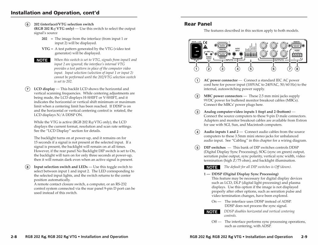
Rear PanelThe features described in this section apply to both models.
DD
SP
SO
GS
ER
RN
EG
SY
NC
V S
YN
C W
IDT
H75
OH
M 1
75 O
HM
2N
O B
AC
KL
IGH
T
AUDIOINPUT
POWER
MBC
REMOTE1
1 2
2ANALOG
100-240 0.2A
50/60 Hz OUTPUTSINPUTS
R
H
G
V
B
S
ANALOGOUTPUT9VDC
1 2 3 4 6 7 85
1 AC power connector — Connect a standard IEC AC powercord here for power input (100VAC to 240VAC, 50/60 Hz) to theinternal, autoswitching power supply.
2 MBC power connectors — These 2.5 mm mini jacks supply9VDC power for buffered monitor breakout cables (MBCs).Connect the MBCs’ power plugs here.
3 Analog computer-video inputs 1 (top) and 2 (bottom) —Connect the source computers to these 9-pin D male connectors.Adapters and monitor breakout cables are available from Extronfor use with SGI, Sun, and Macintosh computers.
4 Audio inputs 1 and 2 — Connect audio cables from the sourcecomputers to these 3.5mm mini stereo jacks for unbalancedaudio input. See “Cabling” in this chapter for a wiring diagram.
5 DIP switches — This bank of DIP switches controls DDSP(Digital Display Sync Processing), SOG (sync on green) output,serration pulse output, sync polarity, vertical sync width, videotermination (high Z/75 ohm), and backlight illumination.
The default for all DIP switches is Off (down).
1 — DDSP (Digital Display Sync Processing)This feature may be necessary for digital display devicessuch as LCD, DLP (digital light processing) and plasmadisplays. Use this option if the image is not displayedproperly after other options, such as serration pulse andvideo termination changes, have been explored.
On — The interface uses DDSP instead of ADSP.DDSP does not process the sync signal.
DDSP disables horizontal and vertical centeringcontrols.
Off — The interface performs sync processing operations,such as centering, with ADSP.
2-8 2-9
RGB 202 Rxxxxxiiiii, RGB 202 Rxxxxxiiiii VTG • Installation and OperationRGB 202 Rxxxxxiiiii, RGB 202 Rxxxxxiiiii VTG • Installation and Operation
Installation and Operation, cont’d
2 — SOG (sync on green)
On — The interface outputs sync on green.
Off — The interface outputs both separate horizontal andvertical sync (on the H and V connectors) andcomposite sync (on the S connector) for RGBHV orRGBS, respectively.
3 — Serr (serration pulse) — Many LCD and DLP projectorsand plasma displays, must have serration pulses removedfrom the sync signal in order to be displayed properly.Flagging or bending at the top of the video image is a signthat the serration pulses should be removed.
On — The interface outputs serration pulses in the verticalsync interval.
Off — The interface does not output serration pulses.
4 — Neg Sync — This switch controls sync polarity.On — Both the horizontal and the vertical sync signals
are forced to negative polarity on output.Off — Output sync polarity follows (is the same as) input
polarity.
5 — V Sync Width (vertical sync pulse width) — For somedigital display devices, if no picture appears, the picturecuts in and out, or it is scrambled, try adjusting the outputvertical sync pulse width or switching from ADSP to DDSP.
On — The vertical sync pulse is narrow.Off — The vertical sync pulse is wide.
6 & 7 — 75 Ohm (video input termination) — DIP switches6 and 7 provide termination for video inputs 1 and 2,respectively. Video termination can be accomplished byusing a laptop breakout cable, by connecting a terminationadapter or a local monitor to a monitor breakout cable(MBC), by using an MBC buffer cable, or by setting atermination switch on the interface.
DIP switches 6 and 7 provide a termination method toprevent blooming when a monitor breakout cable is usedbut no local monitor or termination adapter is connected.
On — The interface provides 75 ohm video inputtermination.
Off — The interface provides high Z (high impedance)video input termination.
8 — No Backlight — This switch controls illumination of theLCD backlight.
On — The LCD backlight is off, except for three secondsat power-up.
Off — The LCD backlight is on while a signal is present atthe selected input.
6 BNC output connectors — These female BNC connectors are forred (R), green (G), and blue (B) video output, andhorizontal (H), vertical (V). and composite (S) sync output.
7 Remote control connector — Connect a contact closure remotecontrol device or an RS-232 device (control system or PCcomputer) to this 9-pin D female connector for remote switchingbetween inputs.Software for RS-232 control is included with the interface. Seechapter 3, “Remote Control” for details.
8 Stereo audio output connector — This 3.5 mm, 5-pole captivescrew connector is for balanced audio output. See “Cabling” fora wiring guide.
CablingThe application diagram in this section shows how the systemlooks when cabling is completed. Attach cables to the interfaceas follows:
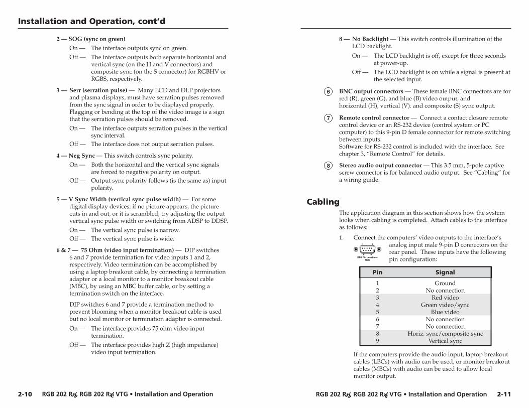
1. Connect the computers’ video outputs to the interface’sanalog input male 9-pin D connectors on therear panel. These inputs have the followingpin configuration:
Pin Signal
1 Ground2 No connection3 Red video4 Green video/sync5 Blue video6 No connection7 No connection8 Horiz. sync/composite sync9 Vertical sync
If the computers provide the audio input, laptop breakoutcables (LBCs) with audio can be used, or monitor breakoutcables (MBCs) with audio can be used to allow localmonitor output.
DB9 Pin LocationsMale
1 5
6 9
2-10 2-11
RGB 202 Rxxxxxiiiii, RGB 202 Rxxxxxiiiii VTG • Installation and OperationRGB 202 Rxxxxxiiiii, RGB 202 Rxxxxxiiiii VTG • Installation and Operation
Installation and Operation, cont’d
Most laptop or notebook computers have an externalvideo port, but they require special commands to outputthe video to that connector. Also, laptops’ screens shutoff once that port is activated. See the computer’s user’sguide for details, or contact Extron for a list of laptopkeyboard commands.
2. Connect the unbalanced stereo audio sources (computer orother devices such as a CD player) tothe front panel.
Wire the audio jack as shown here.
3. Connect the display device’s (projector’s, monitor’s)coaxial BNC cable to the rear panel BNC connectors.
For RGBHV (separate H and V sync) output,connect the cables as shown at left.
For composite sync (RGBS), connect the synccable to the connector labeled “S”.
For sync on green (SOG, RGsB), connect thecables as shown here, and also select the SOGoption on the rear panel DIP switch.
4. Connect the local monitors to the monitor breakout cablesif they were used in step 1 to connect the computers to theinterface. Set the 75 ohm DIP switches to On if no localmonitor is used with a connected MBC cable.
5. Connect an audio device, such as powered speakers, to therear panel stereo audio output connector for balanced orunbalanced audio output. Following the wiring guideshown below, insert the wires into the appropriateopenings in the captive screw connector. Tighten thescrews on top to fasten the wires, then insert the wiredaudio connector into the audio output connector on theinterface rear panel.
For unbalanced output, connect the sleeve toground (GND). Connecting the sleeve to a negative(-) terminal will damage the audio output circuits.
Unbalanced Output
AU
DIO
AU
DIO
TipSee Warning
Sleeve (s)Tip
See Warning
Balanced OutputTip
RingSleeve (s)
TipRing
LR
LR
Wiring the audio output connector
RGB 202 R
RS-232 ControlSystem orComputer
Laptop Computer
Sun Workstation
MBC Buffer
CRT Projector
Stereo Audio
Hi Carol
Hi Carol
DD
SP
SO
GS
ER
RN
EG
SY
NC
V S
YN
C W
IDT
H75
OH
M 1
75 O
HM
2N
O B
AC
KL
IGH
T
AUDIO
INPUT
POWER
MBC
REMOTE
1
1
22
ANALOG
100-240 0
.2A
50/60 Hz
OUTPUTS
INPUTS
R
H
G
V
B
S
ANALOG
OUTPUT
9VDC
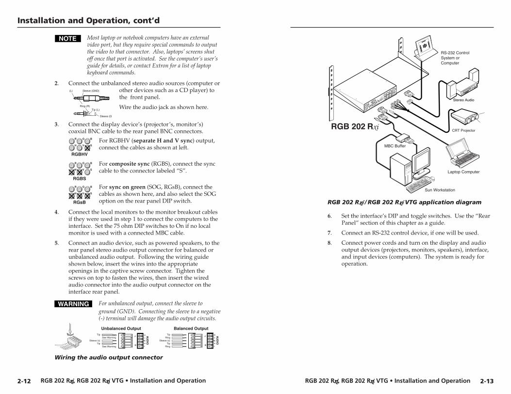
RGB 202 Rxixixixixi / RGB 202 Rxixixixixi VTG application diagram
6. Set the interface’s DIP and toggle switches. Use the “RearPanel” section of this chapter as a guide.
7. Connect an RS-232 control device, if one will be used.
8. Connect power cords and turn on the display and audiooutput devices (projectors, monitors, speakers), interface,and input devices (computers). The system is ready foroperation.
2-132-12
RGBHV
R
H
G
V
B
S
RGBS
R
H
G
V
B
S
RGsB
R
H
G
V
B
S
(L) Sleeve (GND)
Tip (L)Ring (R)
Sleeve (G
RGB 202 Rxxxxxiiiii, RGB 202 Rxxxxxiiiii VTG • Installation and OperationRGB 202 Rxxxxxiiiii, RGB 202 Rxxxxxiiiii VTG • Installation and Operation
Installation and Operation, cont’d
2-14 2-15
LCD DisplayThe RGB 202 Rxi and RGB 202 Rxi VTG’s front panel LCDdisplay serves two main functions: to display the scanning ratesof the input signal, and to indicate the horizontal and verticalcentering limits. During VTG operation, the RGB 202 Rxi VTG’sLCD displays the VTG format, resolution and refresh rates.
LCD screen backlightThe LCD screen lights for 15 seconds at power-up, and it staysbacklit as long as an input signal is present at the selected input.To force the backlight to remain off at all times except at power-up, set the rear panel No Backlight DIP switch to On.See page 2-11 for details.
Scan rate indicationWhen the interface is powered on, the LCD lights for 15 secondswhile it determines whether an input sync signal is present. Ifthe No Backlight DIP switch is set to On, the LCD lights forthree seconds only.
• If the interface does not detect an input sync signal, theLCD goes dark and displays “NO SIGNAL” until theinterface receives an active sync signal.
• If the interface detects an input sync signal, the LCDdisplays the horizontal and vertical scan rates (syncfrequencies) in the following format:
Hxxx.xxkVxxx.xHz
The first line shows the horizontal rate in kilohertz, andthe second line shows the vertical rate in Hertz.
CenteringWhile the vertical ( ) or horizontal ( ) centering (shift)controls are being adjusted, the LCD displays “H-SHIFT” or“V-SHIFT”, respectively. That message remains on the LCD (inplace of the scan rates) until the centering control has beeninactive for 3 seconds. When a centering control reaches itsminimum or maximum limit, the LCD displays “MIN” or“MAX” on the line below “H-SHIFT” or “V-SHIFT”.
If the centering controls are no longer active, the centeringsettings are saved, and the LCD displays the current scan rates.
If the DDSP DIP switch is set to On and a centering control isrotated, the LCD displays N/A DDSP ON, and the image doesnot shift on screen.
Operating the VTG (RGB 202 Rxixixixixi VTG only)The RGB 202 Rxi VTG includes a limited video test generator.The VTG creates and outputs standard test patterns at fixedformats and resolutions so that a system can be set up andtested even when an input computer is not available.
To use the VTG, follow these steps:
1. Set the front panel 202/VTG selection switch to VTG.
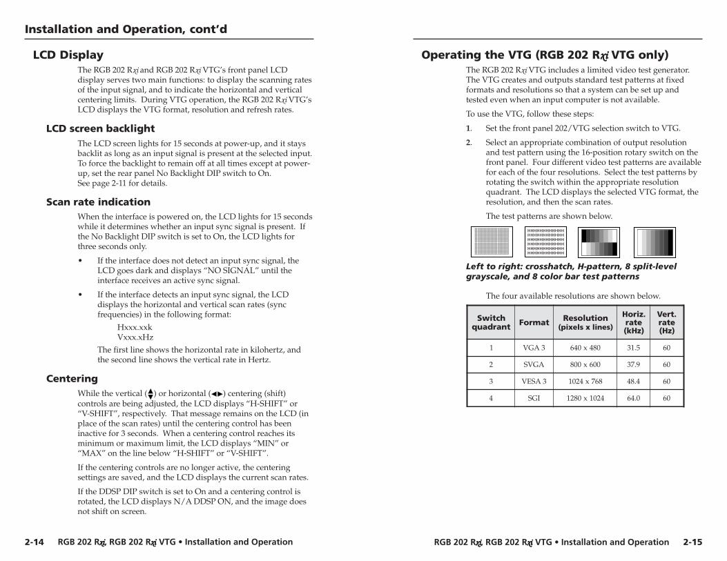
2. Select an appropriate combination of output resolutionand test pattern using the 16-position rotary switch on thefront panel. Four different video test patterns are availablefor each of the four resolutions. Select the test patterns byrotating the switch within the appropriate resolutionquadrant. The LCD displays the selected VTG format, theresolution, and then the scan rates.
The test patterns are shown below.
Left to right: crosshatch, H-pattern, 8 split-levelgrayscale, and 8 color bar test patterns
The four available resolutions are shown below.
hctiwStnardauq tamroF noituloseR
)senilxslexip(
.ziroHetar)zHk(
.treVetar)zH(
1 3AGV 084x046 5.13 06
2 AGVS 006x008 9.73 06
3 3ASEV 867x4201 4.84 06
4 IGS 4201x0821 0.46 06
RGB 202 Rxxxxxiiiii, RGB 202 Rxxxxxiiiii VTG • Installation and OperationRGB 202 Rxxxxxiiiii, RGB 202 Rxxxxxiiiii VTG • Installation and Operation
Installation and Operation, cont’d
2-16 2-17
6. If the image appears and is stable, but it has ghosting orblooming, check the high Z/75 ohm video inputtermination. If changing the termination doesn’t solve theproblem, try using a different input cable.
7. If the picture is faint or cuts out and the signal is weak, thevideo input may be double-terminated. If a local monitoror a termination adapter is attached to the input’s monitorbreakout cable, or if a laptop breakout cable is used, makesure that the 75 ohm video input termination DIP switchesare set to Off (for high Z termination).
8. If the picture from a new source computer does not seemcorrectly centered, the input position memory presetsmight require resetting. To reset the input positionmemories, do the following:
a. Unplug the interface’s AC power cord.
b. Hold the input selection switch up (toward input 1)while reconnecting the power cord to the interfaceand the power source
c. Select the appropriate input, and adjust thehorizontal and vertical centering.
9. If the image still does not display correctly, call Extron’scustomer support hotline.
If the interface does not respond to controls
1. If the picture does not move on screen when the horizontaland vertical centering controls are rotated, DDSP is in use.Set the DDSP DIP switch to Off.
2. If the RGB 202 Rxi VTG does not switch between inputswhen a remote control is used, the front panel 202/VTGtoggle switch might be set to VTG. Use the switch to select202 in order to use a remote control.
When the 202/VTG switch is set to VTG, signals frominput1 and input 2 are ignored; the interface’s internalvideo test generator provides a test pattern in place of thecomputer video input. Input selection (selection ofinput 1 or input 2) cannot be performed until the202/VTG selection switch is set to 202.
TroubleshootingTurn on the input devices (computer, audio device) and outputdevice(s) (projector, monitors, speakers). The image should nowappear on the screen, and sound should be audible.
If the image does not appear or there is no sound
1. Ensure that all devices are plugged in.
2. Make sure that each device is receiving power. Theinterface’s front panel LED lights if the interface isreceiving power and an active sync signal.
3. Check the cabling and the audio connector wiring andgrounding, and make adjustments as needed.
4. Verify that the 75 ohm video input termination DIPswitches have been set correctly.
5. For digital display devices (including LCD, DLP andplasma devices), try turning DDSP on or off using the rearpanel DIP switch.
6. To test the system setup and output, substitute a video testgenerator for one of the computer inputs. Use the VTGthat is built into the RGB 202 Rxi VTG, or use a stand-aloneVTG with the RGB 202 Rxi. To use a stand-alone VTG,unplug the input/output devices’ and interface’s powercords, replace the video source with a VTG, then reconnectpower cords to restore AC power.
7. Call Extron’s customer support hotline if needed.
If the image is not displayed correctly
1. If the output image looks too green, the sync on green(SOG) DIP switch may be set to On, and the display devicemay not be configured to handle SOG signals.Set SOG to Off.
2. If the picture bends or flags at the top of the screen, set theserration pulse DIP switch to Off.
3. For a display device that experiences intermittent glitches,try turning DDSP on or off using the rear panel DIPswitch.
4. If the picture “hangs off” the edges of the screen, adjust thecentering controls ( , ).
5. If the edges of the image seem to exceed their boundariesor if thin lines and sharp edges look thick and fuzzy, trychanging the Level/Boost or Peak Control settings. If theimage is too bright, decrease the boost or peaking level.
RGB 202 Rxxxxxiiiii, RGB 202 Rxxxxxiiiii VTG • Installation and Operation
Installation and Operation, cont’d
RGB 202 Rxxxxxiiiii, RGB 202 Rxxxxxiiiii VTG
3Chapter Three
Remote Control
RS-232 Programmer’s Guide
Contact Closure Control
2-18
RGB 202 Rxxxxxiiiii, RGB 202 Rxxxxxiiiii VTG • Remote ControlRGB 202 Rxxxxxiiiii, RGB 202 Rxxxxxiiiii VTG • Remote Control
Remote Control, cont’dRemote Control
3-2
RECONFIG When a change is made via a front panel control or anotheroperation occurs that must be written to a new memory block,the interface sends the reconfiguration message. No response isrequired from the RS-232 host, but the host may request a newstatus listing via the request information command (I/i). Seethe command/response table in this chapter for details.
Chn X2 The input number has been changed or,for the RGB 202 Rxi VTG, the VTG has been turned on or off.
Error responsesWhen the interface receives a valid SIS command, it executes thecommand and sends a response to the host device. If theinterface is unable to execute the command because thecommand is invalid or it contains invalid parameters, it returnsan error response to the host.
The error response codes and their descriptions are as follows:E01 – Invalid input number (the number is too large or small;
occurs when attempting to select VTG mode via RS-232)E06 – Invalid input selection (occurs when selecting an input when
the RGB 202 Rxi VTG is set to VTG mode)E10 – Invalid commandE13 – Invalid value (the number is out of range/too large)
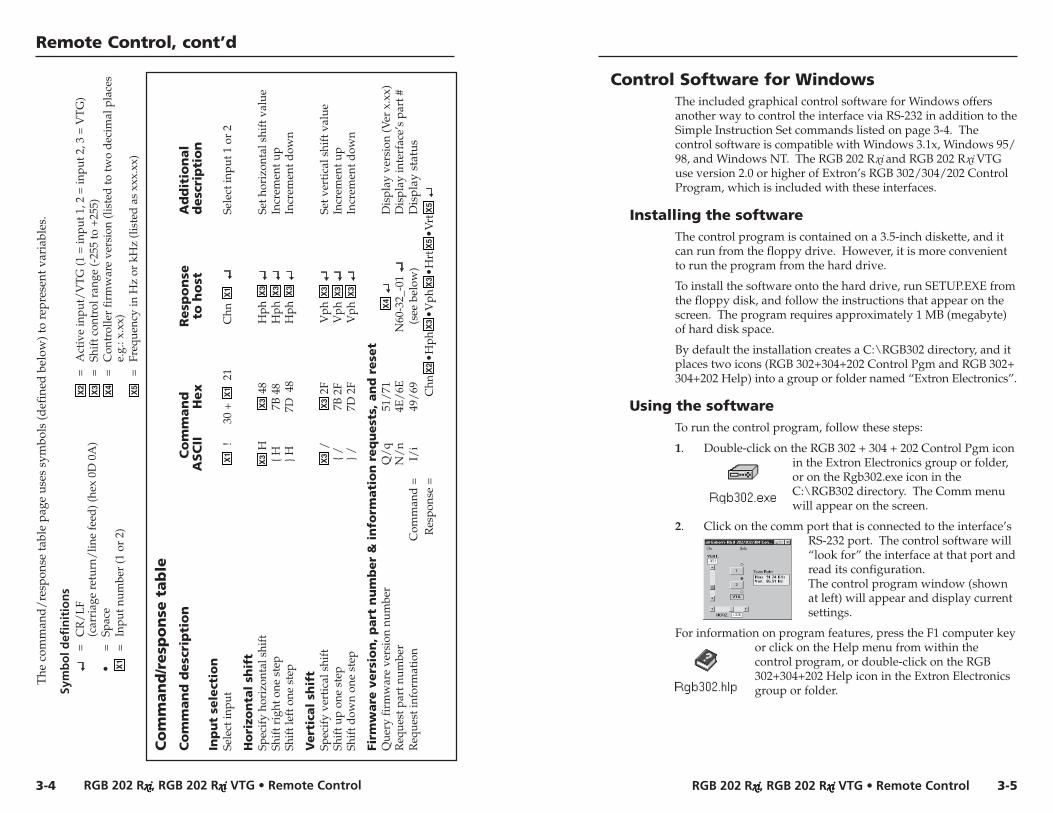
Using the command/response tableThe command/response table lists valid command ASCII codes,the interface’s responses to the host, and a description of thecommand’s function or the results of executing the command.Lower case characters are acceptable in the command field onlywhere indicated. The ASCII to HEX conversion table below isfor use with the command/response table.
ASCII to HEX Conversion Table
•
There are three ways to control input selection and centeringfeatures of an RGB 202 Rxi /RGB 202 Rxi VTG interface: by usingthe front panel controls, by using an RS-232 remote controldevice, and by using a contact closure keypad.
RS-232 Programmer’s GuideThe interface can be remotely controlled via a host computer orother device (such as a control system) attached to the rear panel9-pin D RS-232 connector. The protocol is 9600 baud, 1 stop bit,no parity, and no flow control.
The control device (host) can use either Extron’s Simple Instruc-tion Set (SIS) commands or the graphical control program forWindows. RS-232 control software is included with the interface.
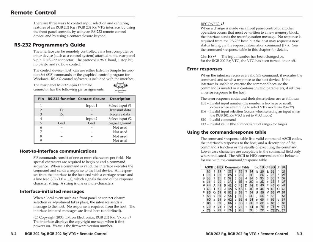
The rear panel RS-232 9-pin D femaleconnector has the following pin assignments:
Pin RS-232 function Contact closure Description
1 – Input 1 Select input #12 Tx – Transmit data3 Rx – Receive data4 – Input 2 Select input #25 Gnd Gnd Signal ground6 – – Not used7 – – Not used8 – – Not used9 – – Not used
Host-to-interface communicationsSIS commands consist of one or more characters per field. Nospecial characters are required to begin or end a commandsequence. When a command is valid, the interface executes thecommand and sends a response to the host device. All respon-ses from the interface to the host end with a carriage return anda line feed (CR/LF = ), which signals the end of the responsecharacter string. A string is one or more characters.
Interface-initiated messagesWhen a local event such as a front panel or contact closureselection or adjustment takes place, the interface sends amessage to the host. No response is required from the host. Theinterface-initiated messages are listed here (underlined).
(C) Copyright 2000, Extron Electronics, RGB 202 Rxi, Vx.xx The interface displays the copyright message when it firstpowers on. Vx.xx is the firmware version number.
DB9 Pin LocationsFemale
5 1
9 6
3-3
RGB 202 Rxxxxxiiiii, RGB 202 Rxxxxxiiiii VTG • Remote ControlRGB 202 Rxxxxxiiiii, RGB 202 Rxxxxxiiiii VTG • Remote Control
Remote Control, cont’d
3-53-4
The
com
man
d/
resp
onse
tabl
e pa
ge u
ses
sym
bols
(def
ined
bel
ow) t
o re
pres
ent v
aria
bles
.
Sym
bo
l def
init
ion
s=
CR
/L
F(c
arri
age
retu
rn/
line
feed
) (he
x 0D
0A
)•
=Sp
ace
X1
=In
put n
umbe
r (1
or
2)
X2
=A
ctiv
e in
put/
VT
G (1
= in
put 1
, 2 =
inpu
t 2, 3
= V
TG
)X
3=
Shif
t con
trol
ran
ge (-
255
to +
255)
X4
=C
ontr
olle
r fi
rmw
are
vers
ion
(lis
ted
to tw
o d
ecim
al p
lace
se.
g.: x
.xx)
X5
=Fr
eque
ncy
in H
z or
kH
z (l
iste
d a
s xx
x.xx
)
Co
mm
an
d/r
esp
on
se t
ab
le
Co
mm
an
d d
esc
rip
tio
nC
om
man
dR
esp
on
seA
dd
itio
nal
ASC
IIH
ex
to h
ost
des
crip
tio
nIn
pu
t se
lect
ion
Sele
ct in
put
X1
!30
+ X
1 2
1C
hn X
1
Sele
ct in
put 1
or
2
Ho
rizo
nta
l sh
ift
Spec
ify
hori
zont
al s
hift
X3
HX
3 4
8H
ph X
3
Set h
oriz
onta
l shi
ft v
alue
Shif
t rig
ht o
ne s
tep
{ H7B
48
Hph
X3
In
crem
ent u
pSh
ift l
eft o
ne s
tep
} H7D
48
Hph
X3
In
crem
ent d
own
Vert
ical
shif
tSp
ecif
y ve
rtic
al s
hift
X3
/X
3 2
FV
ph X
3
Set v
erti
cal s
hift
val
ueSh
ift u
p on
e st
ep{ /
7B 2
FV
ph X
3
Incr
emen
t up
Shif
t dow
n on
e st
ep} /
7D 2
FV
ph X
3
Incr
emen
t dow
n
Firm
ware
vers
ion
, p
art
nu
mb
er
& i
nfo
rmati
on
req
uest
s, a
nd
rese
tQ
uery
firm
war
e ve
rsio
n nu
mbe
rQ
/q
51/
71X
4
Dis
play
ver
sion
(Ver
x.x
x)R
eque
st p
art n
umbe
rN
/n
4E/
6EN
60-3
2_-0
1 D
ispl
ay in
terf
ace’
s pa
rt #
Req
uest
info
rmat
ion
Com
man
d =
I/i
49/
69(s
ee b
elow
)D
ispl
ay s
tatu
sR
espo
nse
=C
hnX
2•H
phX
3•V
phX
3•H
rtX
5•V
rtX
5
Control Software for WindowsThe included graphical control software for Windows offersanother way to control the interface via RS-232 in addition to theSimple Instruction Set commands listed on page 3-4. Thecontrol software is compatible with Windows 3.1x, Windows 95/98, and Windows NT. The RGB 202 Rxi and RGB 202 Rxi VTGuse version 2.0 or higher of Extron’s RGB 302/304/202 ControlProgram, which is included with these interfaces.
Installing the softwareThe control program is contained on a 3.5-inch diskette, and itcan run from the floppy drive. However, it is more convenientto run the program from the hard drive.
To install the software onto the hard drive, run SETUP.EXE fromthe floppy disk, and follow the instructions that appear on thescreen. The program requires approximately 1 MB (megabyte)of hard disk space.
By default the installation creates a C:\RGB302 directory, and itplaces two icons (RGB 302+304+202 Control Pgm and RGB 302+304+202 Help) into a group or folder named “Extron Electronics”.
Using the softwareTo run the control program, follow these steps:
1. Double-click on the RGB 302 + 304 + 202 Control Pgm iconin the Extron Electronics group or folder,or on the Rgb302.exe icon in theC:\RGB302 directory. The Comm menuwill appear on the screen.
2. Click on the comm port that is connected to the interface’sRS-232 port. The control software will“look for” the interface at that port andread its configuration.The control program window (shownat left) will appear and display currentsettings.
For information on program features, press the F1 computer keyor click on the Help menu from within thecontrol program, or double-click on the RGB302+304+202 Help icon in the Extron Electronicsgroup or folder.
RGB 202 Rxxxxxiiiii, RGB 202 Rxxxxxiiiii VTG • Remote Control
Remote Control, cont’d
RGB 202 Rxxxxxiiiii, RGB 202 Rxxxxxiiiii VTG
AAppendix
Specifications, Accessories andPart Numbers
Specifications
Included Parts
Optional Accessories
Cables
Contact Closure Remote ControlFor remote control of input selection only, connect a contactclosure remote control device to the rear panel 9-pin D femaleRemote connector. See the pin assignment table on page 3-2.
3-6
RGB 202 Rxxxxxiiiii, RGB 202 Rxxxxxiiiii VTG • SpecificationsRGB 202 Rxxxxxiiiii, RGB 202 Rxxxxxiiiii VTG • Specifications
Specifications, cont’d
A-3
Specifications, Accessories, Part Numbers
A-2
VideoRouting .......................................... 2 x 1 routerGain ............................................... 0.5V to 1.45V p-pBandwidth .................................... 300 MHz (-3dB)Rise time ........................................ 1.5 nS
Video inputNumber/signal type ................... 2 analog RGBHV, RGBS, RGsB, RsGsBsConnectors .................................... 2 9-pin D male for MBC/LBC cable or
bufferMinimum/maximum levels ...... Analog ....... 0.3V to 1.45V p-p with no
offset at unity gainImpedance .................................... 75 ohms or high Z, switchable (set to
75 ohms if no local monitor is connected)Horizontal frequency .................. 15 kHz to 150 kHzVertical frequency ....................... 40 Hz to 140 HzReturn loss .................................... -30dB @ 5 MHzMaximum DC offset .................... 4V
Video signal characteristics — RGB 202 Rxixixixixi VTG onlyDot clock ....................................... VGA 25.18 MHz, Mac 30.04 MHz, SVGA
65.04 MHz, SGI 107.4 MHz ..Pixel clock accuracy ..................... > 99.02%Scan rate accuracy ....................... > 99.03%Frequency range .......................... VGA ..... 31.475 kHz x 60 Hz,
SVGA ... 37.879 kHz x 60 Hz,XGA ..... 48.392 kHz x 60 Hz,SGI ........ 63.928 kHz x 60 Hz
Rise/fall time ............................... 2.5 nS / 2.0 nS, measured
Video outputNumber/signal type ................... 1 analog RGBHV, RGBS, RGsBConnectors .................................... 6 BNC femaleMinimum/maximum levels ...... 0.3V to 1.30V p-p with 0.7V p-p nominal
input levelImpedance .................................... 75 ohmsReturn loss .................................... -30dB @ 5 MHzDC offset ....................................... ±5mV maximum with input at 0 offset
SyncInput type ..................................... RGBHV, RGBS, RGsB, RsGsBsOutput type .................................. RGBHV, RGBS, RGsB
Input level ..................................... 2V to 5.5V p-p with ±0.2VDC offset max.Output level .................................. TTL ............. 4V to 5V p-pInput impedance .......................... 10 kohmsOutput impedance ...................... 75 ohmsMax. propagation delay .............. 85 nSMax. rise/fall time ....................... 2 nSPolarity .......................................... RGBHV ...................... tracks polarity (or
force negative syncvia DIP switch)
RGBS, RGsB .............. negative
AudioRouting .......................................... 2 x 1 stereo routerGain ............................................... Unbalanced 0dB, balanced +6dBFrequency response ..................... 20 Hz to 20 kHz, ±0.05dBTHD + Noise ................................ 0.03% @ 1 kHz, 0.3% @ 20 kHz at rated
maximum output driveS/N ................................................ >90dB at rated maximum output drive
(17dBu), balancedCrosstalk ....................................... <-90dB @ 1 kHz, fully loadedStereo channel separation .......... >90dB @ 1 kHz to 20 kHz
Audio inputNumber/signal type ................... 2 PC level stereo, unbalancedConnectors .................................... 2 3.5 mm stereo jacks (female) (2
channel); tip (L), ring (R), sleeve (ground)Impedance .................................... >10 kohms, unbalanced, DC coupledMaximum level ............................ +8.5dBu, (balanced or unbalanced) at
stated %THD+N
Audio outputNumber/signal type ................... 1 buffered stereo (2 channel), balanced/
unbalancedConnectors .................................... 1 3.5 mm, captive screw connector, 5-poleImpedance .................................... 50 ohms unbalanced, 100 ohms balancedGain error ...................................... ±0.1dB channel to channelMaximum level (Hi-Z) ................ >+14dBu, balanced at stated %THD+NMaximum level (600 ohm) ......... >+8.5dBm, balanced at stated %THD+N
0dBu = 0.775 volts (RMS).
RGB 202 Rxxxxxiiiii, RGB 202 Rxxxxxiiiii VTG • Specifications
Specifications, cont’d
RGB 202 Rxxxxxiiiii, RGB 202 Rxxxxxiiiii VTG • Accessories and Part NumbersA-4 A-5
Included PartsThese items are included in each order for a RGB 202 Rxi or aRGB 202 Rxi VTG:
Included parts Part number
RGB 202 Rxi/RGB 202 Rxi VTG 60-327-01/60-328-01
3.5 mm, 5-pole captive screw connector 10-319-10
RGB 202 Rxi/202 Rxi VTG User’s Manual 68-500-01
Rubber feet
IEC power cord
Windows-based control software 29-035-01
Tweeker
Optional Accessories
Accessories Part number
Under-desk mounting bracket kit 70-077-01
Through-desk mounting bracket kit 70-077-02
1U rack shelf 60-190-01
3.5 mm stereo plug 10-306-01
Installation cable(bulk 14-conductor, non-plenum) 22-120-02
Installation cable(bulk 17-conductor, plenum) 22-111-03
Cables
Monitor breakout cables Part number
MBC VGA/XGA HR 26-162-01
MBC Mac/Quadra 26-018-01
MBC Sun Sparc HR 26-424-01
MBC SGI/13W3 HR 26-425-01
Control/remote — interfaceSerial control port ........................ RS-232, 9-pin female D connector (also
used for contact closure)Baud rate and protocol ............... 9600, 8-bit, 1 stop bit, no paritySerial control pin configuration .. 2 = TX, 3 = RX, 5 = GNDContact closure ............................ 1 9-pin female D connector (also used for
RS-232)Contact closure pin configuration . 1 = input #1, 4 = input #2, 5 = GNDProgram control ........................... Extron’s control program for Windows
Extron’s Simple Instruction Set™ – SIS™
GeneralInput power .................................. 100VAC to 240VAC, 50/60 Hz, 18 watts,
internal, auto-switchableMBC power jacks ......................... 9.0VDC, 0.15ATemperature/humidity .............. Storage -40° to +158°F (-40° to +70°C) /
10% to 90%, non-condensingOperating +32° to +113°F (0° to +45°C) /10% to 90%, non-condensing
Rack mount ................................... Yes, with an optional rack shelf (part#60-190-01)
Furniture mount .......................... Yes, with an optional under-deskmounting kit (part #70-077-01) orthrough-desk mounting kit (part #70-077-02)
Enclosure type .............................. Metal, ventedEnclosure dimensions ................. 1.75" H x 8.75" W x 8.0" D (1U high, half
rack width)4.4 cm H x 22.2 cm W x 20.3 cm Dwith rear BNCs ........ D = 8.4" (21.3 cm)(Depth excludes knobs.)
Product weight ............................. RGB 202 Rxi ................. 2.2 lbs (1.0 kg)RGB 202 Rxi VTG ..... 2.3 lbs (1.0 kg)
Shipping weight ........................... 5 lbs (2.3 kg)Vibration ....................................... ISTA/NSTA 1A in carton (International
Safe Transit Association)Listings .......................................... UL, CULCompliances ................................. CE, FCC Class AMTBF ............................................. 30,000 hoursWarranty ....................................... 3 years parts and labor
Specifications are subject to change without notice.
RGB 202 Rxxxxxiiiii, RGB 202 Rxxxxxiiiii VTG • Accessories and Part Numbers
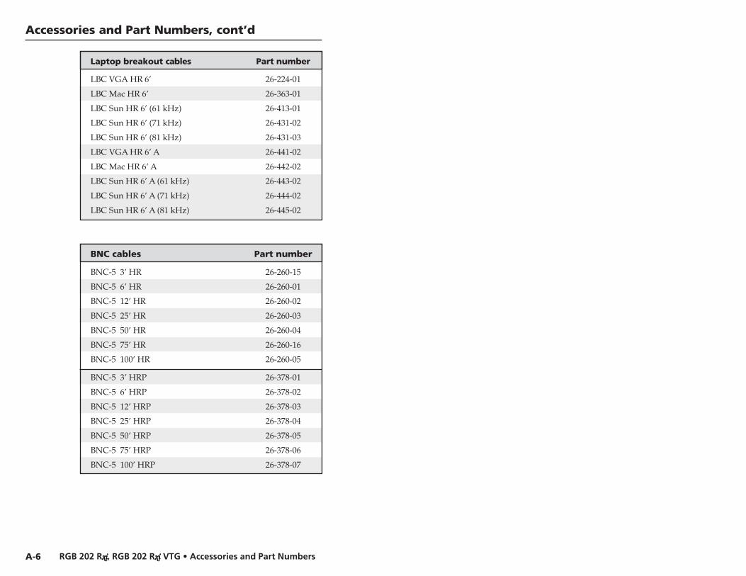
Accessories and Part Numbers, cont’d
Laptop breakout cables Part number
LBC VGA HR 6’ 26-224-01
LBC Mac HR 6’ 26-363-01
LBC Sun HR 6’ (61 kHz) 26-413-01
LBC Sun HR 6’ (71 kHz) 26-431-02
LBC Sun HR 6’ (81 kHz) 26-431-03
LBC VGA HR 6’ A 26-441-02
LBC Mac HR 6’ A 26-442-02
LBC Sun HR 6’ A (61 kHz) 26-443-02
LBC Sun HR 6’ A (71 kHz) 26-444-02
LBC Sun HR 6’ A (81 kHz) 26-445-02
BNC cables Part number
BNC-5 3’ HR 26-260-15
BNC-5 6’ HR 26-260-01
BNC-5 12’ HR 26-260-02
BNC-5 25’ HR 26-260-03
BNC-5 50’ HR 26-260-04
BNC-5 75’ HR 26-260-16
BNC-5 100’ HR 26-260-05
BNC-5 3’ HRP 26-378-01
BNC-5 6’ HRP 26-378-02
BNC-5 12’ HRP 26-378-03
BNC-5 25’ HRP 26-378-04
BNC-5 50’ HRP 26-378-05
BNC-5 75’ HRP 26-378-06
BNC-5 100’ HRP 26-378-07
A-6