rfc 8661 segment routing mpls interworking with ldp · entries in the mpls data plane. sr, ldp ,...
TRANSCRIPT

RFC 8661Segment Routing MPLS Interworking with LDP
AbstractA Segment Routing (SR) node steers a packet through a controlled set of instructions, calledsegments, by prepending the packet with an SR header. A segment can represent any instruction,topological or service based. SR allows enforcing a flow through any topological path whilemaintaining per-flow state only at the ingress node to the SR domain.
The Segment Routing architecture can be directly applied to the MPLS data plane with no changein the forwarding plane. This document describes how Segment Routing MPLS operates in anetwork where LDP is deployed and in the case where SR-capable and non-SR-capable nodescoexist.
Stream: Internet Engineering Task Force (IETF)RFC: 8661Category: Standards TrackPublished: December 2019 ISSN: 2070-1721Authors:
A. Bashandy, Ed.Individual
C. Filsfils, Ed.Cisco Systems, Inc.
S. PrevidiHuawei Technologies
B. DecraeneOrange
S. LitkowskiOrange
Status of This Memo This is an Internet Standards Track document.
This document is a product of the Internet Engineering Task Force (IETF). It represents theconsensus of the IETF community. It has received public review and has been approved forpublication by the Internet Engineering Steering Group (IESG). Further information on InternetStandards is available in Section 2 of RFC 7841.
Information about the current status of this document, any errata, and how to provide feedbackon it may be obtained at .https://www.rfc-editor.org/info/rfc8661
Copyright Notice Copyright (c) 2019 IETF Trust and the persons identified as the document authors. All rightsreserved.
This document is subject to BCP 78 and the IETF Trust's Legal Provisions Relating to IETFDocuments ( ) in effect on the date of publication of thisdocument. Please review these documents carefully, as they describe your rights and restrictions
https://trustee.ietf.org/license-info
Bashandy, et al. Standards Track Page 1

with respect to this document. Code Components extracted from this document must includeSimplified BSD License text as described in Section 4.e of the Trust Legal Provisions and areprovided without warranty as described in the Simplified BSD License.
RFC 8661 Segment Routing and LDP December 2019
Bashandy, et al. Standards Track Page 2

Table of Contents 1. Introduction
1.1. Requirements Language
2. SR-LDP Ships-in-the-Night Coexistence
2.1. MPLS2MPLS, MPLS2IP, and IP2MPLS Coexistence
3. SR and LDP Interworking
3.1. LDP to SR
3.1.1. LDP to SR Behavior
3.2. SR to LDP
3.2.1. Segment Routing Mapping Server (SRMS)
3.2.2. SR to LDP Behavior
3.2.3. Interoperability of Multiple SRMSes and Prefix-SID Advertisements
4. SR-LDP Interworking Use Cases
4.1. SR Protection of LDP-Based Traffic
4.2. Eliminating Targeted LDP Sessions
4.3. Guaranteed FRR Coverage
4.4. Inter-AS Option C, Carrier's Carrier
5. IANA Considerations
6. Manageability Considerations
6.1. SR and LDP Coexistence
6.2. Data-Plane Verification
7. Security Considerations
8. References
8.1. Normative References
8.2. Informative References
Appendix A. Migration from LDP to SR
Acknowledgements
RFC 8661 Segment Routing and LDP December 2019
Bashandy, et al. Standards Track Page 3

Contributors
Authors' Addresses
1. Introduction Segment Routing, as described in , can be used on top of the MPLS data plane withoutany modification as described in .
Segment Routing control plane can coexist with current label distribution protocols such as LDP .
This document outlines the mechanisms through which SR interworks with LDP in cases where amix of SR-capable and non-SR-capable routers coexist within the same network and moreprecisely in the same routing domain.
Section 2 describes the coexistence of SR with other MPLS control-plane protocols. Section 3documents the interworking between SR and LDP in the case of nonhomogeneous deployment. Section 4 describes how a partial SR deployment can be used to provide SR benefits to LDP-basedtraffic including a possible application of SR in the context of interdomain MPLS use cases. Appendix A documents a method to migrate from LDP to SR-based MPLS tunneling.
Typically, an implementation will allow an operator to select (through configuration) which ofthe described modes of SR and LDP coexistence to use.
1.1. Requirements Language The key words " ", " ", " ", " ", " ", " ", "
", " ", " ", " ", and " " in this document are tobe interpreted as described in BCP 14 when, and only when, they appear inall capitals, as shown here.
[RFC8402][RFC8660]
[RFC5036]
MUST MUST NOT REQUIRED SHALL SHALL NOT SHOULD SHOULDNOT RECOMMENDED NOT RECOMMENDED MAY OPTIONAL
[RFC2119] [RFC8174]
2. SR-LDP Ships-in-the-Night Coexistence "MPLS Control-Plane Client (MCC)" refers to any control-plane protocol installing forwardingentries in the MPLS data plane. SR, LDP , RSVP-TE , BGP , etc., areexamples of MCCs.
An MCC, operating at Node N, must ensure that the incoming label it installs in the MPLS dataplane of Node N has been uniquely allocated to itself.
Segment Routing makes use of the Segment Routing Global Block (SRGB, as defined in )for the label allocation. The use of the SRGB allows SR to coexist with any other MCC.
[RFC5036] [RFC3209] [RFC8277]
[RFC8402]
RFC 8661 Segment Routing and LDP December 2019
Bashandy, et al. Standards Track Page 4

This is clearly the case for the adjacency segment: it is a local label allocated by the labelmanager, as is the case for any MCC.
This is clearly the case for the prefix segment: the label manager allocates the SRGB set of labelsto the SR MCC client, and the operator ensures the unique allocation of each global prefixsegment or label within the allocated SRGB set.
Note that this static label-allocation capability of the label manager has existed for many yearsacross several vendors and is therefore not new. Furthermore, note that the label manager'sability to statically allocate a range of labels to a specific application is not new either. This isrequired for MPLS-TP operation. In this case, the range is reserved by the label manager, and it isthe MPLS-TP Network Management System (acting as an MCC) that ensures the uniqueallocation of any label within the allocated range and the creation of the related MPLSforwarding entry.
Let us illustrate an example of ship-in-the-night (SIN) coexistence.
The EVEN VPN service is supported by PE2 and PE4 while the ODD VPN service is supported byPE1 and PE3. The operator wants to tunnel the ODD service via LDP and the EVEN service via SR.
This can be achieved in the following manner:
• The operator configures PE1, PE2, PE3, and PE4 with respective loopbacks 192.0.2.201/32,192.0.2.202/32, 192.0.2.203/32, and 192.0.2.204/32. These PEs advertised their VPN routes withnext hop set on their respective loopback address.
• The operator configures A, B, C with respective loopbacks 192.0.2.1/32, 192.0.2.2/32,192.0.2.3/32.
• The operator configures PE2, A, B, C, and PE4 with SRGB [100, 300]. • The operator attaches the respective Node Segment Identifiers (Node SIDs, as defined in
), 202, 101, 102, 103, and 204, to the loopbacks of nodes PE2, A, B, C, and PE4. TheNode SIDs are configured to request Penultimate Hop Popping.
• PE1, A, B, C, and PE3 are LDP capable. • PE1 and PE3 are not SR capable.
PE3 sends an ODD VPN route to PE1 with next-hop 192.0.2.203 and VPN label 10001.
From an LDP viewpoint, PE1 received an LDP label binding (1037) for a Forwarding EquivalenceClass (FEC) 192.0.2.203/32 from its next-hop A; A received an LDP label binding (2048) for thatFEC from its next-hop B; B received an LDP label binding (3059) for that FEC from its next-hop C;and C received implicit NULL LDP binding from its next-hop PE3.
[RFC5960]
Figure 1: SIN Coexistence
PE2 PE4 \ / PE1----A----B---C---PE3
[RFC8402]
RFC 8661 Segment Routing and LDP December 2019
Bashandy, et al. Standards Track Page 5

As a result, PE1 sends its traffic to the ODD service route advertised by PE3 to next-hop A withtwo labels: the top label is 1037 and the bottom label is 10001. Node A swaps 1037 with 2048 andforwards to B; B swaps 2048 with 3059 and forwards to C; C pops 3059 and forwards to PE3.
PE4 sends an EVEN VPN route to PE2 with next-hop 192.0.2.204 and VPN label 10002.
From an SR viewpoint, PE2 maps the IGP route 192.0.2.204/32 onto Node SID 204; Node A swaps204 with 204 and forwards to B; B swaps 204 with 204 and forwards to C; and C pops 204 andforwards to PE4.
As a result, PE2 sends its traffic to the VPN service route advertised by PE4 to next-hop A withtwo labels: the top label is 204 and the bottom label is 10002. Node A swaps 204 with 204 andforwards to B. B swaps 204 with 204 and forwards to C. C pops 204 and forwards to PE4.
The two modes of MPLS tunneling coexist.
• The ODD service is tunneled from PE1 to PE3 through a continuous LDP LSP traversing A, B,and C.
• The EVEN service is tunneled from PE2 to PE4 through a continuous SR node segmenttraversing A, B, and C.
2.1. MPLS2MPLS, MPLS2IP, and IP2MPLS Coexistence MPLS2MPLS refers to the forwarding behavior where a router receives a labeled packet andswitches it out as a labeled packet. Several MPLS2MPLS entries may be installed in the data planefor the same prefix.
Let us examine A's MPLS forwarding table as an example:
Incoming label: 1037
◦ Outgoing label: 2048
◦ Outgoing next hop: B
Note: This entry is programmed by LDP for 192.0.2.203/32.
Incoming label: 203
◦ Outgoing label: 203
◦ Outgoing next hop: B
Note: This entry is programmed by SR for 192.0.2.203/32.
These two entries can coexist because their incoming label is unique. The uniqueness isguaranteed by the label manager allocation rules.
The same applies for the MPLS2IP forwarding entries. MPLS2IP is the forwarding behaviorwhere a router receives a labeled IPv4/IPv6 packet with one label only, pops the label, andswitches the packet out as IPv4/IPv6. For IP2MPLS coexistence, refer to Section 6.1.
RFC 8661 Segment Routing and LDP December 2019
Bashandy, et al. Standards Track Page 6

3. SR and LDP Interworking This section analyzes the case where SR is available in one part of the network and LDP isavailable in another part. It describes how a continuous MPLS tunnel can be built throughout thenetwork.
Let us analyze the following example:
• P6, P7, P8, PE4, and PE3 are LDP capable. • PE1, PE2, P5, and P6 are SR capable. PE1, PE2, P5, and P6 are configured with SRGB (100, 200)
and with node segments 101, 102, 105, and 106, respectively. • A service flow must be tunneled from PE1 to PE3 over a continuous MPLS tunnel
encapsulation; therefore, SR and LDP need to interwork.
Figure 2: SR and LDP Interworking
PE2 PE4 \ / PE1----P5--P6--P7--P8---PE3
<-----SR----> <------LDP------>
3.1. LDP to SR In this section, a right-to-left traffic flow is analyzed.
PE3 has learned a service route whose next hop is PE1. PE3 has an LDP label binding from thenext-hop P8 for the FEC "PE1". Therefore, PE3 sends its service packet to P8 as per classic LDPbehavior.
P8 has an LDP label binding from its next-hop P7 for the FEC "PE1" and therefore, P8 forwards toP7 as per classic LDP behavior.
P7 has an LDP label binding from its next-hop P6 for the FEC "PE1" and therefore, P7 forwards toP6 as per classic LDP behavior.
P6 does not have an LDP binding from its next-hop P5 for the FEC "PE1". However, P6 has an SRnode segment to the IGP route "PE1". Hence, P6 forwards the packet to P5 and swaps its local LDPlabel for FEC "PE1" by the equivalent node segment (i.e., 101).
P5 pops 101 (assuming PE1 advertised its node segment 101 with the penultimate-pop flag set)and forwards to PE1.
PE1 receives the tunneled packet and processes the service label.
The end-to-end MPLS tunnel is built by stitching an LDP LSP from PE3 to P6 and the related nodesegment from P6 to PE1.
RFC 8661 Segment Routing and LDP December 2019
Bashandy, et al. Standards Track Page 7

3.1.1. LDP to SR Behavior
It has to be noted that no additional signaling or state is required in order to provideinterworking in the direction LDP to SR.
An SR node having LDP neighbors create LDP bindings for each Prefix-SID learned in theSR domain by treating SR-learned labels as if they were learned through an LDP neighbor. Inaddition, for each FEC, the SR node stitches the incoming LDP label to the outgoing SR label. Thishas to be done in both LDP-independent and ordered label distribution control modes as definedin .
MUST
[RFC5036]
3.2. SR to LDP In this section, the left-to-right traffic flow is analyzed.
This section defines the Segment Routing Mapping Server (SRMS). The SRMS is an IGP nodeadvertising mapping between Segment Identifiers (SID) and prefixes advertised by other IGPnodes. The SRMS uses a dedicated IGP extension (IS-IS, OSPFv2, and OSPFv3), which is protocolspecific and defined in , , and .
The SRMS function of an SR-capable router allows distribution of mappings for prefixes notlocally attached to the advertising router and therefore allows advertisement of mappings onbehalf of non-SR-capable routers.
The SRMS is a control-plane-only function that may be located anywhere in the IGP floodingscope. At least one SRMS server exist in a routing domain to advertise Prefix-SIDs on behalfof non‑SR nodes, thereby allowing non-LDP routers to send and receive labeled traffic from LDP-only routers. Multiple SRMSes may be present in the same network (for redundancy). Thisimplies that there are multiple ways a prefix-to-SID mapping can be advertised. Conflictsresulting from inconsistent advertisements are addressed by .
The example depicted in Figure 2 assumes that the operator configures P5 to act as a SegmentRouting Mapping Server and advertises the following mappings: (P7, 107), (P8, 108), (PE3, 103),and (PE4, 104).
The mappings advertised by one or more SRMSes result from local policy information configuredby the operator.
If PE3 had been SR capable, the operator would have configured PE3 with node segment 103.Instead, as PE3 is not SR capable, the operator configures that policy at the SRMS and it is thelatter that advertises the mapping.
The Mapping Server Advertisements are only understood by SR-capable routers. The SR-capablerouters install the related node segments in the MPLS data plane exactly like the node segmentshad been advertised by the nodes themselves.
For example, PE1 installs the node segment 103 with next-hop P5 exactly as if PE3 had advertisednode segment 103.
[RFC8665] [RFC8666] [RFC8667]
MUST
[RFC8660]
RFC 8661 Segment Routing and LDP December 2019
Bashandy, et al. Standards Track Page 8

PE1 has a service route whose next hop is PE3. PE1 has a node segment for that IGP route: 103with next-hop P5. Hence, PE1 sends its service packet to P5 with two labels: the bottom label isthe service label and the top label is 103.
P5 swaps 103 for 103 and forwards to P6.
P6's next hop for the IGP route "PE3" is not SR capable (P7 does not advertise the SR capability).However, P6 has an LDP label binding from that next hop for the same FEC (e.g., LDP label 1037).Hence, P6 swaps 103 for 1037 and forwards to P7.
P7 swaps this label with the LDP label received from P8 and forwards to P8.
P8 pops the LDP label and forwards to PE3.
PE3 receives the tunneled packet and processes the service label.
The end-to-end MPLS tunnel is built by stitching an SR node segment from PE1 to P6 and an LDPLSP from P6 to PE3.
SR-mapping advertisement for a given prefix provides no information about Penultimate HopPopping. Other mechanisms, such as IGP-specific mechanisms ( , , and
), be used to determine the Penultimate Hop Popping in such case.
Note: In the previous example, Penultimate Hop Popping is not performed at the SR-LDP border for segment 103 (PE3), because none of the routers in the SR domain arePenultimate Hop for segment 103. In this case, P6 requires the presence of thesegment 103 such as to map it to the LDP label 1037.
[RFC8665] [RFC8666][RFC8667] MAY
3.2.1. Segment Routing Mapping Server (SRMS)
This section specifies the concept and externally visible functionality of a Segment RoutingMapping Server (SRMS).
The purpose of SRMS functionality is to support the advertisement of Prefix-SIDs to a prefixwithout the need to explicitly advertise such assignment within a prefix reachabilityadvertisement. Examples of explicit Prefix-SID Advertisement are the Prefix-SID sub-TLVsdefined in , , and .
The SRMS functionality allows assigning of Prefix-SIDs to prefixes owned by non-SR-capablerouters as well as to prefixes owned by SR-capable nodes. It is the former capability that isessential to the SR-LDP interworking described later in this section.
The SRMS functionality consists of two functional blocks: the Mapping Server (MS) and MappingClient (MC).
[RFC8665] [RFC8666] [RFC8667]
RFC 8661 Segment Routing and LDP December 2019
Bashandy, et al. Standards Track Page 9

An MS is a node that advertises an SR mappings. Advertisements sent by an MS define theassignment of a Prefix-SID to a prefix independent of the advertisement of reachability to theprefix itself. An MS advertise SR mappings for any prefix whether or not it advertisesreachability for the prefix and irrespective of whether that prefix is advertised by or evenreachable through any router in the network.
An MC is a node that receives and uses the MS mapping advertisements. Note that a node may beboth an MS and an MC. An MC interprets the SR-mapping advertisement as an assignment of aPrefix-SID to a prefix. For a given prefix, if an MC receives an SR-mapping advertisement from aMapping Server and also has received a Prefix-SID Advertisement for that same prefix in a prefixreachability advertisement, then the MC prefer the SID advertised in the prefixreachability advertisement over the Mapping Server Advertisement, i.e., the Mapping ServerAdvertisement be ignored for that prefix. Hence, assigning a Prefix-SID to a prefix usingthe SRMS functionality does not preclude assigning the same or different Prefix-SID(s) to thesame prefix using explicit Prefix-SID Advertisement such as the aforementioned Prefix-SID sub-TLVs.
For example, consider an IPv4 prefix advertisement received by an IS‑IS router in the ExtendedIP reachability TLV (TLV 135). Suppose TLV 135 contained the Prefix-SID sub-TLV. If the routerthat receives TLV 135 with the Prefix-SID sub-TLV also received an SR-mapping advertisement forthe same prefix through the SID/Label Binding TLV, then the receiving router must prefer thePrefix-SID sub-TLV over the SID/Label Binding TLV for that prefix. Refer to for detailsabout the Prefix-SID sub-TLV and SID/Label Binding TLV.
MAY
MUST
MUST
[RFC8667]
3.2.2. SR to LDP Behavior
SR to LDP interworking requires an SRMS as defined above.
Each SR-capable router installs in the MPLS data-plane Node SIDs learned from the SRMS exactlyas if these SIDs had been advertised by the nodes themselves.
An SR node having LDP-only neighbors stitch the incoming SR label (whose SID isadvertised by the SRMS) to the outgoing LDP label.
It has to be noted that the SR to LDP behavior does not propagate the status of the LDP FEC thatwas signaled by LDP when configured in ordered mode.
It has to be noted that in the case of SR to LDP, the label binding is equivalent to the independentLDP Label Distribution Control Mode where a label is bound to a FEC independentlyfrom the received binding for the same FEC.
MUST
[RFC5036]
3.2.3. Interoperability of Multiple SRMSes and Prefix-SID Advertisements
In the case of SR-LDP interoperability through the use of an SRMS, mappings are advertised byone or more SRMSes.
RFC 8661 Segment Routing and LDP December 2019
Bashandy, et al. Standards Track Page 10

SRMS functionality is implemented in the link-state protocol (such as IS-IS and OSPF). Link-stateprotocols allow propagation of updates across area boundaries and, therefore, SRMSadvertisements are propagated through the usual inter-area advertisement procedures in link-state protocols.
Multiple SRMSes can be provisioned in a network for redundancy. Moreover, a preferencemechanism may also be used among SRMSes to deploy a primary/secondary SRMS schemeallowing controlled modification or migration of SIDs.
The content of SRMS advertisement (i.e., mappings) are a matter of local policy determined bythe operator. When multiple SRMSes are active, it is necessary that the information (mappings)advertised by the different SRMSes is aligned and consistent. The following mechanism is appliedto determine the preference of SRMS advertisements:
If a node acts as an SRMS, it advertise a preference to be associated with all SRMS SIDAdvertisements sent by that node. The means of advertising the preference is defined in theprotocol-specific documents, e.g., , , and . The preference value isan unsigned 8-bit integer with the following properties:
Advertisement of a preference value is optional. Nodes that do not advertise a preference valueare assigned a preference value of 128.
An MCC on a node receiving one or more SRMS mapping advertisements applies them as follows:
• For any prefix for which it did not receive a Prefix-SID Advertisement, the MCC applies theSRMS mapping advertisements with the highest preference. The mechanism by which aPrefix-SID is advertised for a given prefix is defined in the protocol specifications ,
, and . • If there is an incoming label collision as specified in , apply the steps specified in
to resolve the collision.
When the SRMS advertises mappings, an implementation should provide a mechanism throughwhich the operator determines which of the IP2MPLS mappings are preferred among the oneadvertised by the SRMS and the ones advertised by LDP.
MAY
[RFC8665] [RFC8666] [RFC8667]
0 Reserved value indicating advertisements from that node be used
1-255 Preference value (255 is most preferred)
Table 1
MUST NOT
[RFC8665][RFC8666] [RFC8667]
[RFC8660][RFC8660]
4. SR-LDP Interworking Use Cases SR can be deployed, for example, to enhance LDP transport. The SR deployment can be limited tothe network region where the SR benefits are most desired.
RFC 8661 Segment Routing and LDP December 2019
Bashandy, et al. Standards Track Page 11

4.1. SR Protection of LDP-Based Traffic In Figure 3, let us assume:
• All link costs are 10 except FG, which is 30. • All routers are LDP capable. • X, Y, and Z are PEs participating in an important service S. • The operator requires 50 msec link-based Fast Reroute (FRR) for service S. • A, B, C, D, E, F, and G are SR capable. • X, Y, and Z are not SR capable, e.g., as part of a staged migration from LDP to SR, the operator
deploys SR first in a subpart of the network and then everywhere.
The operator would like to resolve the following issues:
• To protect the link BA along the shortest-path of the important flow XY, B requires a RemoteLoop-Free Alternate (RLFA; see ) repair tunnel to D and, therefore, a targeted LDPsession from B to D. Typically, network operators prefer avoiding these dynamicallyestablished multi-hop LDP sessions in order to reduce the number of protocols running inthe network and, therefore, simplify network operations.
• There is no LFA/RLFA solution to protect the link BE along the shortest path of the importantflow XZ. The operator wants a guaranteed link-based FRR solution.
The operator can meet these objectives by deploying SR only on A, B, C, D, E, F, and G:
• The operator configures A, B, C, D, E, F, and G with SRGB [100, 200] and with node segments101, 102, 103, 104, 105, 106, and 107, respectively.
• The operator configures D as an SR Mapping Server with the following policy mapping: (X,201), (Y, 202), and (Z, 203).
• Each SR node automatically advertises a local adjacency segment for its IGP adjacencies.Specifically, F advertises adjacency segment 9001 for its adjacency FG.
A, B, C, D, E, F, and G keep their LDP capability. Therefore, the flows XY and XZ are transportedover end-to-end LDP LSPs.
Figure 3: SR-LDP Interworking Example
X | Y--A---B---E--Z | | \ D---C--F--G 30
[RFC7490]
RFC 8661 Segment Routing and LDP December 2019
Bashandy, et al. Standards Track Page 12

For example, LDP at B installs the following MPLS data-plane entries:
Incoming label: local LDP label bound by B for FEC Y
◦ Outgoing label: LDP label bound by A for FEC Y
◦ Outgoing next hop: A
Incoming label: local LDP label bound by B for FEC Z
◦ Outgoing label: LDP label bound by E for FEC Z
◦ Outgoing next hop: E
The novelty comes from how the backup chains are computed for these LDP-based entries. WhileLDP labels are used for the primary next- hop and outgoing labels, SR information is used for theFRR construction. In steady state, the traffic is transported over LDP LSP. In transient FRR state,the traffic is backup thanks to the SR-enhanced capabilities.
The RLFA paths are dynamically precomputed as defined in . Typically,implementations allow to enable an RLFA mechanism through a simple configuration commandthat triggers both the precomputation and installation of the repair path. The details on howRLFA mechanisms are implemented and configured is outside the scope of this document andnot relevant to the aspects of SR-LDP interwork explained in this document.
This helps meet the requirements of the operator:
• Eliminate targeted LDP sessions. • Provide guaranteed FRR coverage. • Keep the traffic over LDP LSP in steady state. • Partially deploy SR only where needed.
[RFC7490]
4.2. Eliminating Targeted LDP Sessions B's MPLS entry to Y becomes:
Incoming label: local LDP label bound by B for FEC Y
◦ Outgoing label: LDP label bound by A for FEC Y
◦ Backup outgoing label: SR node segment for Y {202}
◦ Outgoing next hop: A
◦ Backup next hop: repair tunnel: node segment to D {104} with outgoing next hop: C
It has to be noted that D is selected as a Remote Loop-Free Alternate (RLFA) as defined in .
In steady state, X sends its Y-destined traffic to B with a top label, which is the LDP label bound byB for FEC Y. B swaps that top label for the LDP label bound by A for FEC Y and forwards to A. Apops the LDP label and forwards to Y.
[RFC7490]
RFC 8661 Segment Routing and LDP December 2019
Bashandy, et al. Standards Track Page 13

Upon failure of the link BA, B swaps the incoming top label with the node segment for Y (202)and sends the packet onto a repair tunnel to D (node segment 104). Thus, B sends the packet to Cwith the label stack {104, 202}. C pops the node segment 104 and forwards to D. D swaps 202 for202 and forwards to A. A's next hop to Y is not SR capable, and therefore, Node A swaps theincoming node segment 202 to the LDP label announced by its next hop (in this case, implicitNULL).
After IGP convergence, B's MPLS entry to Y will become:
Incoming label: local LDP label bound by B for FEC Y
◦ Outgoing label: LDP label bound by C for FEC Y
◦ Outgoing next hop: C
And the traffic XY travels again over the LDP LSP.
Conclusion: the operator has eliminated the need for targeted LDP sessions (no longer required)and the steady-state traffic is still transported over LDP. The SR deployment is confined to thearea where these benefits are required.
Despite that, in general, an implementation would not require a manual configuration oftargeted LDP sessions. However, it is always a gain if the operator is able to reduce the set ofprotocol sessions running on the network infrastructure.
4.3. Guaranteed FRR Coverage As mentioned in Section 4.1, in the example topology described in Figure 3, there is no RLFA-based solution for protecting the traffic flow YZ against the failure of link BE because there is nointersection between the extended P-space and Q-space (see for details). However:
• G belongs to the Q space of Z. • G can be reached from B via a "repair SR path" {106, 9001} that is not affected by failure of
link BE. (The method by which G and the repair tunnel to it from B are identified are outsidethe scope of this document.)
B's MPLS entry to Z becomes:
Incoming label: local LDP label bound by B for FEC Z
◦ Outgoing label: LDP label bound by E for FEC Z
◦ Backup outgoing label: SR node segment for Z {203}
◦ Outgoing next hop: E
◦ Backup next hop: repair tunnel to G: {106, 9001}
G is reachable from B via the combination of a node segment to F {106} and an adjacencysegment FG {9001}.
[RFC7490]
RFC 8661 Segment Routing and LDP December 2019
Bashandy, et al. Standards Track Page 14

Note that {106, 107} would have equally worked. Indeed, in many cases, P's shortest path to Qis over the link PQ. The adjacency segment from P to Q is required only in very raretopologies where the shortest-path from P to Q is not via the link PQ.
In steady state, X sends its Z-destined traffic to B with a top label, which is the LDP label bound byB for FEC Z. B swaps that top label for the LDP label bound by E for FEC Z and forwards to E. Epops the LDP label and forwards to Z.
Upon failure of the link BE, B swaps the incoming top label with the node segment for Z (203) andsends the packet onto a repair tunnel to G (node segment 106 followed by adjacency segment9001). Thus, B sends the packet to C with the label stack {106, 9001, 203}. C pops the nodesegment 106 and forwards to F. F pops the adjacency segment 9001 and forwards to G. G swaps203 for 203 and forwards to E. E's next hop to Z is not SR capable, and thus, E swaps the incomingnode segment 203 for the LDP label announced by its next hop (in this case, implicit NULL).
After IGP convergence, B's MPLS entry to Z will become:
Incoming label: local LDP label bound by B for FEC Z
◦ Outgoing label: LDP label bound by C for FEC Z
◦ Outgoing next hop: C
And the traffic XZ travels again over the LDP LSP.
Conclusions:
• the operator has eliminated its second problem: guaranteed FRR coverage is provided. Thesteady-state traffic is still transported over LDP. The SR deployment is confined to the areawhere these benefits are required.
• FRR coverage has been achieved without any signaling for setting up the repair LSP andwithout setting up a targeted LDP session between B and G.
4.4. Inter-AS Option C, Carrier's Carrier In inter-AS Option C , two interconnected ASes sets up inter-AS MPLS connectivity. SRmay be independently deployed in each AS.
In Inter-AS Option C, B2 advertises to B1 a labeled BGP route for PE2, and B1 reflects itto its internal peers, e.g., PE1. PE1 learns from a service route reflector a service route whosenext hop is PE2. PE1 resolves that service route on the labeled BGP route to PE2. That labeled BGProute to PE2 is itself resolved on the AS1 IGP route to B1.
[RFC4364]
Figure 4: Inter-AS Option C
PE1---R1---B1---B2---R2---PE2 <-----------> <-----------> AS1 AS2
[RFC8277]
RFC 8661 Segment Routing and LDP December 2019
Bashandy, et al. Standards Track Page 15

If AS1 operates SR, then the tunnel from PE1 to B1 is provided by the node segment from PE1 toB1.
PE1 sends a service packet with three labels: the top one is the node segment to B1, the next oneis the label in the labeled BGP route provided by B1 for the route "PE2", and the bottom one is theservice label allocated by PE2.
5. IANA Considerations This document has no IANA actions.
6. Manageability Considerations
6.1. SR and LDP Coexistence When both SR and LDP coexist, the following applies:
• If both SR and LDP propose an IP2MPLS entry for the same IP prefix, then by default the LDProute be selected. This is because it is expected that SR is introduced into networksthat contain routers that do not support SR. Hence, by having a behavior that prefers LDPover SR, traffic flow is unlikely to be disrupted.
• A local policy on a router allow to prefer the SR-provided IP2MPLS entry. • Note that this policy be locally defined. There is no requirement that all routers use the
same policy.
SHOULD
MUSTMAY
6.2. Data-Plane Verification When Label switch paths (LSPs) are defined by stitching LDP LSPs with SR LSPs, it is necessary tohave mechanisms allowing the verification of the LSP connectivity as well as validation of thepath. These mechanisms are described in .[RFC8287]
7. Security Considerations This document does not introduce any change to the MPLS data plane and thereforeno additional security of the MPLS data plane is required.
This document introduces another form of label binding advertisements. The security associatedwith these advertisements is part of the security applied to routing protocols such as IS-IS
and OSPF , which both optionally make use of cryptographic authenticationmechanisms. This form of advertisement is more centralized, on behalf of the node advertisingthe IP reachability, which presents a different risk profile. This document also specifies amechanism by which the ill effects of advertising conflicting label bindings can be mitigated. Inparticular, advertisements from the node advertising the IP reachability is more preferred thanthe centralized one. This document recognizes that errors in configuration and/or programmingmay result in false or conflicting label binding advertisements compromising traffic forwarding.Therefore, this document recommends the operator implement strict configuration/
[RFC3031]
[RFC5304] [RFC5709]
RFC 8661 Segment Routing and LDP December 2019
Bashandy, et al. Standards Track Page 16

[RFC2119]
[RFC5036]
[RFC8174]
[RFC8402]
[RFC8660]
[RFC3031]
[RFC3209]
[RFC4364]
[RFC5304]
[RFC5709]
8. References
8.1. Normative References
, , , , , March 1997, .
, , , , October 2007,
.
, , , , , May 2017,
.
, , , , July2018, .
, , , , December 2019, .
8.2. Informative References
, , , , January 2001,
.
, , , ,
December 2001, .
, , , , February 2006,
.
, , , , October 2008, .
, , ,
, October 2009, .
programmability control, the monitoring of the advertised SIDs, the preference of an IPreachability SID Advertisement over a centralized SID Advertisement, and the logging of anyerror message in order to avoid, or at least significantly minimize, the possibility of such risk.
Bradner, S. "Key words for use in RFCs to Indicate Requirement Levels" BCP 14RFC 2119 DOI 10.17487/RFC2119 <https://www.rfc-editor.org/info/rfc2119>
Andersson, L., Ed., Minei, I., Ed., and B. Thomas, Ed. "LDP Specification" RFC5036 DOI 10.17487/RFC5036 <https://www.rfc-editor.org/info/rfc5036>
Leiba, B. "Ambiguity of Uppercase vs Lowercase in RFC 2119 Key Words" BCP14 RFC 8174 DOI 10.17487/RFC8174 <https://www.rfc-editor.org/info/rfc8174>
Filsfils, C., Ed., Previdi, S., Ed., Ginsberg, L., Decraene, B., Litkowski, S., and R.Shakir "Segment Routing Architecture" RFC 8402 DOI 10.17487/RFC8402
<https://www.rfc-editor.org/info/rfc8402>
Bashandy, A., Ed., Filsfils, C., Ed., Previdi, S., Decraene, B., Litkowski, S., and R.Shakir "Segment Routing with MPLS Data Plane" RFC 8660 DOI 10.17487/RFC8660 <https://www.rfc-editor.org/info/rfc8660>
Rosen, E., Viswanathan, A., and R. Callon "Multiprotocol Label SwitchingArchitecture" RFC 3031 DOI 10.17487/RFC3031 <https://www.rfc-editor.org/info/rfc3031>
Awduche, D., Berger, L., Gan, D., Li, T., Srinivasan, V., and G. Swallow "RSVP-TE:Extensions to RSVP for LSP Tunnels" RFC 3209 DOI 10.17487/RFC3209
<https://www.rfc-editor.org/info/rfc3209>
Rosen, E. and Y. Rekhter "BGP/MPLS IP Virtual Private Networks (VPNs)" RFC4364 DOI 10.17487/RFC4364 <https://www.rfc-editor.org/info/rfc4364>
Li, T. and R. Atkinson "IS-IS Cryptographic Authentication" RFC 5304 DOI10.17487/RFC5304 <https://www.rfc-editor.org/info/rfc5304>
Bhatia, M., Manral, V., Fanto, M., White, R., Barnes, M., Li, T., and R. Atkinson"OSPFv2 HMAC-SHA Cryptographic Authentication" RFC 5709 DOI 10.17487/RFC5709 <https://www.rfc-editor.org/info/rfc5709>
RFC 8661 Segment Routing and LDP December 2019
Bashandy, et al. Standards Track Page 17
[RFC5960]
[RFC7490]
[RFC8277]
[RFC8287]
[RFC8355]
[RFC8665]
[RFC8666]
[RFC8667]
, , , , August 2010,
.
, , , , April
2015, .
, , , , October 2017, .
,
, ,, December 2017,
.
, , ,
, March 2018, .
, , , , December 2019, .
, , , , December 2019,
.
, , , ,
December 2019, .
Frost, D., Ed., Bryant, S., Ed., and M. Bocci, Ed. "MPLS Transport Profile DataPlane Architecture" RFC 5960 DOI 10.17487/RFC5960 <https://www.rfc-editor.org/info/rfc5960>
Bryant, S., Filsfils, C., Previdi, S., Shand, M., and N. So "Remote Loop-FreeAlternate (LFA) Fast Reroute (FRR)" RFC 7490 DOI 10.17487/RFC7490
<https://www.rfc-editor.org/info/rfc7490>
Rosen, E. "Using BGP to Bind MPLS Labels to Address Prefixes" RFC 8277 DOI10.17487/RFC8277 <https://www.rfc-editor.org/info/rfc8277>
Kumar, N., Ed., Pignataro, C., Ed., Swallow, G., Akiya, N., Kini, S., and M. Chen"Label Switched Path (LSP) Ping/Traceroute for Segment Routing (SR) IGP-Prefixand IGP-Adjacency Segment Identifiers (SIDs) with MPLS Data Planes" RFC 8287DOI 10.17487/RFC8287 <https://www.rfc-editor.org/info/rfc8287>
Filsfils, C., Ed., Previdi, S., Ed., Decraene, B., and R. Shakir "Resiliency Use Casesin Source Packet Routing in Networking (SPRING) Networks" RFC 8355 DOI10.17487/RFC8355 <https://www.rfc-editor.org/info/rfc8355>
Psenak, P., Ed., Previdi, S., Ed., Filsfils, C., Gredler, H., Shakir, R., Henderickx, W.,and J. Tantsura "OSPF Extensions for Segment Routing" RFC 8665 DOI10.17487/RFC8665 <https://doi.org/10.17487/RFC8665>
Psenak, P., Ed. and S. Previdi "OSPFv3 Extensions for Segment Routing" RFC8666 DOI 10.17487/RFC8666 <https://doi.org/10.17487/RFC8666>
Previdi, S., Ginsberg, L., Filsfils, C., Bashandy, A., Gredler, H., and B. Decraene"IS-IS Extensions for Segment Routing" RFC 8667 DOI 10.17487/RFC8667
<https://doi.org/10.17487/RFC8667>
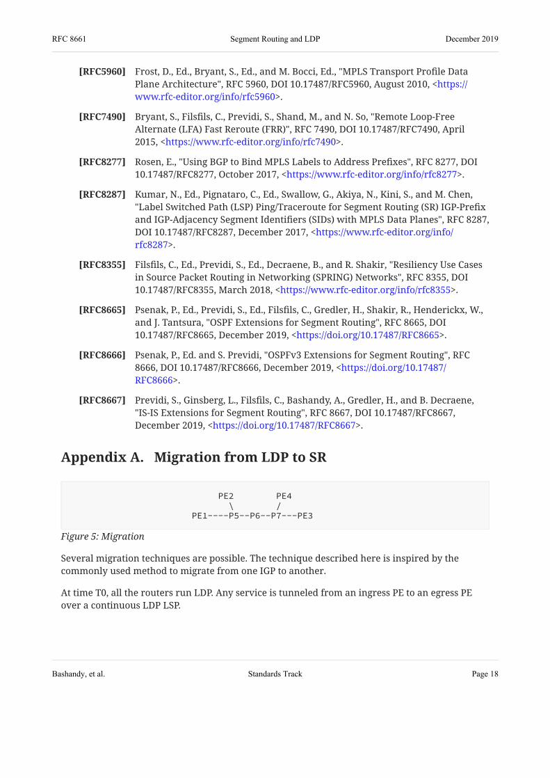
Appendix A. Migration from LDP to SR
Several migration techniques are possible. The technique described here is inspired by thecommonly used method to migrate from one IGP to another.
At time T0, all the routers run LDP. Any service is tunneled from an ingress PE to an egress PEover a continuous LDP LSP.
Figure 5: Migration
PE2 PE4 \ / PE1----P5--P6--P7---PE3
RFC 8661 Segment Routing and LDP December 2019
Bashandy, et al. Standards Track Page 18

At time T1, all the routers are upgraded to SR. They are configured with the SRGB range [100,300]. PE1, PE2, PE3, PE4, P5, P6, and P7 are respectively configured with the node segments 101,102, 103, 104, 105, 106, and 107 (attached to their service-recursing loopback).
Note: At this time, the service traffic is still tunneled over LDP LSPs. For example,PE1 has an SR node segment to PE3 and an LDP LSP to PE3. As seen earlier,however, the LDP IP2MPLS encapsulation is preferred by default. However, it has tobe noted that the SR infrastructure is usable, e.g., for Fast Reroute (FRR) or IGP Loop-Free Convergence to protect existing IP and LDP traffic. FRR mechanisms aredescribed in .
At time T2, the operator enables the local policy at PE1 to prefer SR IP2MPLS encapsulation overLDP IP2MPLS.
The service from PE1 to any other PE is now riding over SR. All other service traffic is stilltransported over LDP LSPs.
At time T3, gradually, the operator enables the preference for SR IP2MPLS encapsulation acrossall the edge routers.
All the service traffic is now transported over SR. LDP is still operational and services couldbe reverted to LDP.
At time T4, LDP is unconfigured from all routers.
[RFC8355]
Acknowledgements The authors would like to thank Pierre Francois, Ruediger Geib, and Alexander Vainshtein fortheir contributions to the content of this document.
Contributors
Edward CrabbeIndividualEmail: [email protected]
Igor MilojevicEmail: [email protected]
Saku YttiTDCEmail: [email protected]
RFC 8661 Segment Routing and LDP December 2019
Bashandy, et al. Standards Track Page 19

Rob ShakirGoogleEmail: [email protected]
Martin HornefferDeutsche TelekomEmail: [email protected]
Wim HenderickxNokiaEmail: [email protected]
Jeff TantsuraApstra, Inc.Email: [email protected]
Les GinsbergCisco SystemsEmail: [email protected]
Authors' Addresses Ahmed Bashandy ( )������IndividualUnited States of America
[email protected] Email:
Clarence Filsfils ( )������Cisco Systems, Inc.BrusselsBelgium
[email protected] Email:
Stefano PrevidiHuawei TechnologiesItaly
[email protected] Email:
Bruno DecraeneOrangeFrance
[email protected] Email:
RFC 8661 Segment Routing and LDP December 2019
Bashandy, et al. Standards Track Page 20

Stephane LitkowskiOrangeFrance
[email protected] Email:
RFC 8661 Segment Routing and LDP December 2019
Bashandy, et al. Standards Track Page 21