rf ceiling pir presence detector switching · single channel switching functionality simple on/off...
TRANSCRIPT

Overview
The EBDHS-AT-PRM is a passive infrared (PIR) motion sensor combined with a switched output channel. The EBDHS-AT-PRM is a high sensitivity PIR detector suitable for high bay applications, such as warehouses and factories, and where high detection sensitivity is needed.
The output channel comprises a mains voltage relay capable of simple on/off switching.
Functioning as a presence detector, the unit can turn lights on when a room is occupied and off when the room is empty. Optional settings allow lights to be turned off in response to ambient daylight. The unit also includes stored scenes for versatile manual on / off control of lighting.
The EBDHS-AT-PRM can be used as a standalone unit or integrated with other devices as part of a system. The built-in RF transceiver allows wireless communication with all other An-10® compatible products, e.g. the AT-BB-IN
Input Unit, useful for push-button scene selection and absence detection.
All functionality is fully programmable.
Features
PIR Sensor Detects movement within the unit’s detection range, allowing load control in response to changes in occupancy. IR Receiver Receives control and programming commands from an IR (infrared) handset. Light Level Sensor Monitors the ambient light level, allowing load control based on minimum and maximum Lux Level. Status LEDs These flash Red and/or Green to indicate the following:
Power Input & Switched Output Connector (Channel 1) Used to connect mains power to the unit and to connect a switched load.
Front features
Back features
Walk Test LED active when movement is detected
Valid setting received
Invalid setting received
Software reset received
Factory reset received
RF ceiling PIR presence detector – Switching
EBDHS-AT-PRM
Product Guide
Sensor Lens which covers...
PIR Sensor IR Receiver
Light Level Sensor Status LEDs
Mounting Bezel
2
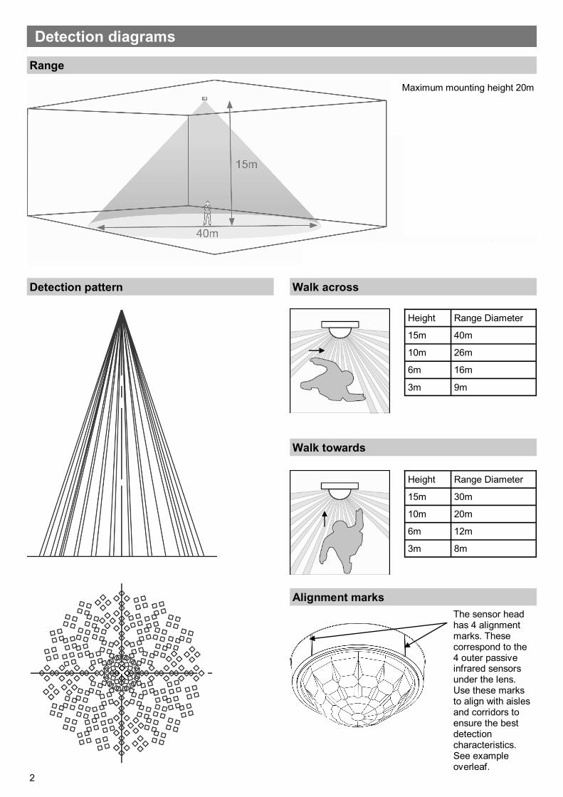
Detection diagrams
Range
Detection pattern Walk across
Maximum mounting height 20m
Walk towards
Height Range Diameter
15m 30m
10m 20m
6m 12m
3m 8m
Height Range Diameter
15m 40m
10m 26m
6m 16m
3m 9m
Alignment marks
The sensor head has 4 alignment marks. These correspond to the 4 outer passive infrared sensors under the lens. Use these marks to align with aisles and corridors to ensure the best detection characteristics. See example overleaf.
3
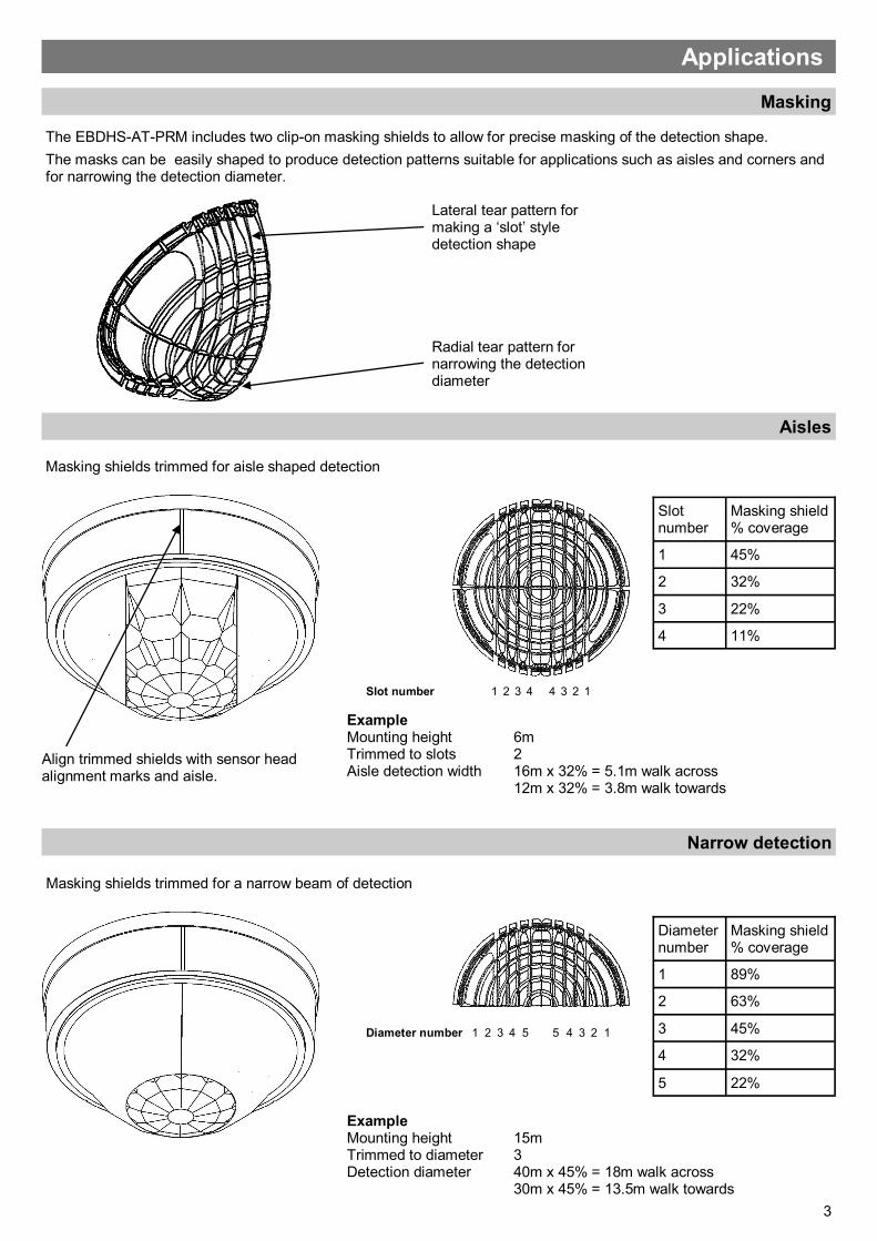
Masking
The EBDHS-AT-PRM includes two clip-on masking shields to allow for precise masking of the detection shape.
The masks can be easily shaped to produce detection patterns suitable for applications such as aisles and corners and for narrowing the detection diameter.
Radial tear pattern for narrowing the detection diameter
Lateral tear pattern for making a ‘slot’ style detection shape
Applications
Aisles
Masking shields trimmed for aisle shaped detection
Narrow detection
Masking shields trimmed for a narrow beam of detection
1 2 3 4 4 3 2 1
Slot number
Masking shield % coverage
1 45%
2 32%
3 22%
4 11%
Slot number
2 3 4
Diameter number
Masking shield % coverage
1 89%
2 63%
3 45%
4 32%
5 22%
5 5 4 3 2 1 Diameter number 1
Example Mounting height 6m Trimmed to slots 2 Aisle detection width 16m x 32% = 5.1m walk across 12m x 32% = 3.8m walk towards
Example Mounting height 15m Trimmed to diameter 3 Detection diameter 40m x 45% = 18m walk across 30m x 45% = 13.5m walk towards
Align trimmed shields with sensor head alignment marks and aisle.
4
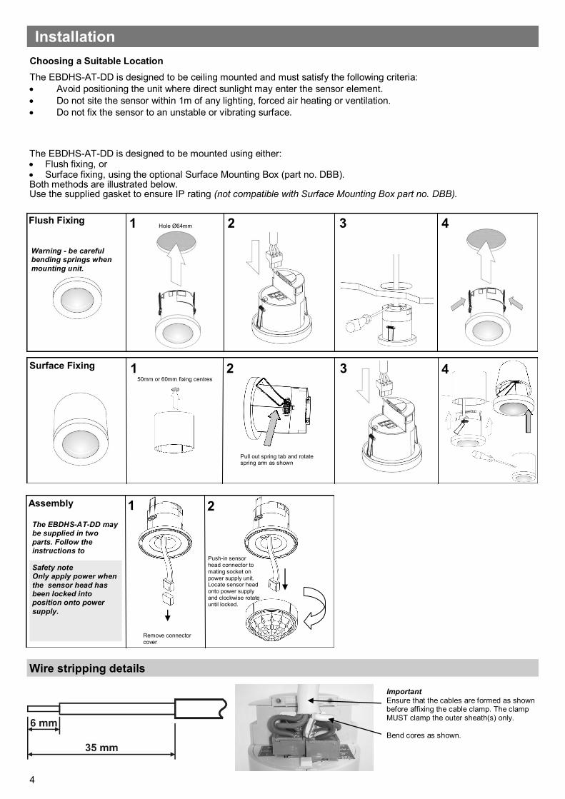
The EBDHS-AT-DD is designed to be mounted using either: Flush fixing, or Surface fixing, using the optional Surface Mounting Box (part no. DBB). Both methods are illustrated below. Use the supplied gasket to ensure IP rating (not compatible with Surface Mounting Box part no. DBB).
Assembly
Remove connector cover
1 2
Push-in sensor head connector to mating socket on power supply unit. Locate sensor head onto power supply and clockwise rotate until locked.
The EBDHS-AT-DD may be supplied in two
parts. Follow the instructions to
Safety note Only apply power when
the sensor head has been locked into position onto power
supply.
Flush Fixing
Surface Fixing
1 2 3
2 3 4 1
Hole Ø64mm
Warning - be careful bending springs when
mounting unit.
4
Pull out spring tab and rotate spring arm as shown
50mm or 60mm fixing centres
Choosing a Suitable Location
The EBDHS-AT-DD is designed to be ceiling mounted and must satisfy the following criteria:
Avoid positioning the unit where direct sunlight may enter the sensor element.
Do not site the sensor within 1m of any lighting, forced air heating or ventilation.
Do not fix the sensor to an unstable or vibrating surface.
Installation
Important
Ensure that the cables are formed as shown before affixing the cable clamp. The clamp MUST clamp the outer sheath(s) only.
Bend cores as shown.
Wire stripping details
5
When power is applied to the unit, the load will turn on immediately. Vacate the room or remain very still and wait for the load to switch off (this should take around 10 minutes). Check that the load switches on when movement is detected. The unit is now ready for programming.
Power-up test procedure
What if the load does not turn ON?
Check that the live supply to the circuit is good.
Check that the load is functioning by bypassing the sensor (e.g. link terminals L and L/ Out on Channel1).
Check that the unit is correctly addressed, see ‘Step 1: Set channel addresses and channel load type’ on page 7.
If the detection range is smaller than expected, check the diagrams in page 2. Rotating the sensor slightly may improve the detection range. HINT: The Walk Test LED function can be used to check that the unit is detecting movement in the required area (see page 8 for further details).
What if the load does not turn OFF?
Ensure that the area is left unoccupied for longer than the Time Adjustment Period (default is 10 minutes).
Ensure that the sensor is not adjacent to circulating air, heaters or lamps. HINT: The Walk Test LED function can be used to check that the unit is detecting movement in the required area (see page 8 for further details).
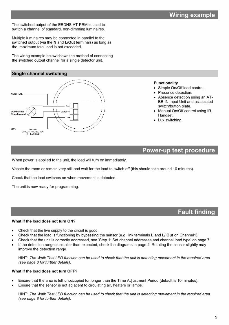
Single channel switching
Functionality
Simple On/Off load control.
Presence detection.
Absence detection using an AT-BB-IN Input Unit and associated switch/button plate.
Manual On/Off control using IR Handset.
Lux switching.
The switched output of the EBDHS-AT-PRM is used to switch a channel of standard, non-dimming luminaires. Multiple luminaires may be connected in parallel to the switched output (via the N and L/Out terminals) as long as the maximum total load is not exceeded. The wiring example below shows the method of connecting the switched output channel for a single detector unit.
Wiring example
Fault finding

6
The functionality of the EBDHS-AT-PRM Sensor is controlled by a number of parameters which can be changed or programmed by any of the following devices:
UHS4 Infrared Handset
UNLCDHS Infrared Handset (with LCD)
For most basic programming operations the UHS4 handset is recommended and the following procedures are based on using this device.
Point the handset at the Sensor and send the required programming commands to the unit as shown in Steps 1, 2 and 3.
Valid commands will be indicated by a green LED flash. See page 1 for details of other LED responses.
.
Step 1: Set channel addresses and channel load type
The Sensor has one output channel:
Channel 1 - Switched Output
and one input channel:
Channel 3 - PIR Sensor
To relate the function of different channels it is necessary to set the addresses correctly. For example, a scene select message sent from a device with a Local Code of 1 will only be actioned by devices that also have a Local Code of 1.
To program the settings for a specific channel on the Sensor you must specify the appropriate channel number (i.e.1 to 3) using the programming device.
If no channel number (or channel 0) is specified, all channels will be set to the same address.
The output channel also has a Circuit number. This allows different physical channels to be linked and controlled as a single Circuit.
Basic programming
7
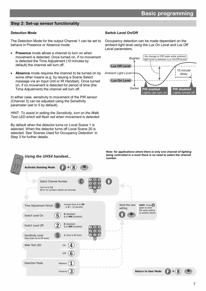
Step 2: Set-up sensor functionality
Detection Mode The Detection Mode for the output Channel 1 can be set to behave in Presence or Absence mode:
Presence mode allows a channel to turn on when movement is detected. Once turned on, if no movement is detected the Time Adjustment (10 minutes by default) the channel will turn off.
Absence mode requires the channel to be turned on by some other means (e.g. by issuing a Scene Select message via an Input Unit or IR Handset). Once turned on, if no movement is detected for period of time (the Time Adjustment) the channel will turn off.
In either case, sensitivity to movement of the PIR sensor (Channel 3) can be adjusted using the Sensitivity parameter (set to 5 by default). HINT: To assist in setting the Sensitivity, turn on the Walk Test LED which will flash red when movement is detected. By default when the detector turns on Local Scene 1 is selected. When the detector turns off Local Scene 20 is selected. See ‘Scenes Used for Occupancy Detection’ in Step 3 for further details.
Switch Level On/Off Occupancy detection can be made dependant on the ambient light level using the Lux On Level and Lux Off Level parameters.
Basic programming
Note: for applications where there is only one channel of lighting
being controlled in a room there is no need to select the channel number.

8
The EBDHS-AT-PRM has capacity to store 20 Local Scenes and 120 Area Scenes. By default all Scenes are pre-programmed with the following channel levels, but these can be changed as required:
NOTE: Local Scene 20 and Area Scene 120 are designated ‘off’ scenes within a system and should normally be programmed with all channels off or at zero. Scenes can be recalled by using an IR Handset or by a switch/button plate via an AT-BB-IN Input Unit.
Local Scenes
1 2 3 4 5 6 ... 19 20
Ch1 on on on on on on ... on off
Area Scenes
101 102 103 104 105 106 ... 119 220
Ch1 on on on on on on ... on off
Step 3: Re-program scenes
Scenes Used for Occupancy Detection If movement is detected (in Presence mode), Local On Scene 1 is selected. By default this switches Channel 1 On. If no movement is detected for the Time Adjustment Period (in Presence or Absence mode), Local Off Scene 20 is selected. By default this switches Channel 1 Off. NOTE: These ‘On’ and ‘Off’ Scene selections cannot be changed using the UHS4 handset. You can, however, reprogram, on or off values, for Scenes 1 and 20 if required.
Note: + and - will toggle between
On and Off.
Basic programming

9
Warehouse
Application example
This example shows a warehouse with 19 light fittings in 4 aisles and 1 corridor. Each storage aisle has 4 fittings connected to 2 EBDHS-AT detectors. These detectors, in each aisle, have an aisle specific Local Code and the same Area codes. The corridor to the right has 3 fittings and 2 detectors, set to a fifth Local Code, and also a member of the aisle’s Area Code. In this arrangement the corridor lighting is activated when an aisle is entered, but the other aisles do not light unless entered. When any of the aisles detectors are activated all of those aisle fittings will be illuminated.

10
Advanced programming
Parameter Name Default Value Range / Options Description Programming
Devices
UHS4 UNLCDHS
For Device
Product ID Automatically
assigned by the device
1 to 999 A number used to uniquely identify each device within a range of
devices that are set to the same Local Code.
Building Code 1 1 to 999 A number shared by all devices that belong to the same building or
system.
Lock 0 Enable (1) or disable
(0)
Lock the An-10 network. Prevents more devices joining the network.
For Channel 1 (Switched Output)
Local Code 1 1 to 999 A number corresponding to the Local Code of all devices to be
controlled by an associated input channel.
Sub Local Code(s) Not set 1 to 99
0 to clear
A number corresponding to the Sub Local Code of all devices to be
controlled by an associated input channel. Up to 20 Sub Local Codes can be set for the switched output Channel 1.
Area Code(s) 999 1 to 999
0 to clear
A number corresponding to the Area Code of all devices to be
controlled by an associated input channel. Up to 32 Area Codes can be set for the switched output Channel 1.
Circuit Number 1 1 to 999 Sets the circuit number for this channel.
Detection Mode Presence Presence or Absence Presence mode allows the output to turn on when movement is
detected and off when movement ceases. Absence mode allows the output to turn off when movement ceases, but must be manually turned on first.
Output State Set by Scene
0-100%
0=off
The current output state of the channel, for example as set by a
Scene Select command.
Raise from off 1 Enable (1) or disable
(0)
Enables raise from off feature.
Lower from off 1 Enable (1) or disable
(0)
Enables lower from off feature.
Lux off period 0 0 to 999 in minutes
(0=15 seconds)
Number of minutes above the Lux Off level before a lux switching
decision is made.
Lux switching
enabled
1 Enable (1) or disable
(0)
Enables or disables the output channel to respond to lux switching
commands.
Detector enabled 1 Enable (1) or disable
(0)
Enables the output channel to be controlled by detector occupancy.
Detector inhibit
period
0 0 to 255 Detector inhibit period in 100s of milliseconds (255 = 25 seconds).
The tables on pages 12 to 14 give a summary of all programmable parameters for the EBDHS-AT-PRM Sensor.
11
Advanced programming
Parameter Name Default Value Range / Options Description Programming
Devices
UHS4 UNLCDHS
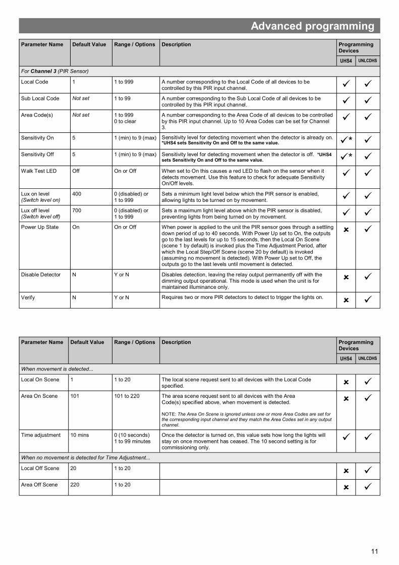
For Channel 3 (PIR Sensor)
Local Code 1 1 to 999 A number corresponding to the Local Code of all devices to be
controlled by this PIR input channel. Sub Local Code Not set 1 to 99 A number corresponding to the Sub Local Code of all devices to be
controlled by this PIR input channel.
Area Code(s) Not set 1 to 999
0 to clear
A number corresponding to the Area Code of all devices to be controlled
by this PIR input channel. Up to 10 Area Codes can be set for Channel 3.
Sensitivity On 5 1 (min) to 9 (max) Sensitivity level for detecting movement when the detector is already on. *UHS4 sets Sensitivity On and Off to the same value. *
Sensitivity Off 5 1 (min) to 9 (max) Sensitivity level for detecting movement when the detector is off. *UHS4 sets Sensitivity On and Off to the same value. *
Walk Test LED Off On or Off When set to On this causes a red LED to flash on the sensor when it
detects movement. Use this feature to check for adequate Sensitivity On/Off levels.
Lux on level (Switch level on)
400 0 (disabled) or
1 to 999
Sets a minimum light level below which the PIR sensor is enabled,
allowing lights to be turned on by movement.
Lux off level (Switch level off)
700 0 (disabled) or
1 to 999
Sets a maximum light level above which the PIR sensor is disabled,
preventing lights from being turned on by movement.
Power Up State On On or Off When power is applied to the unit the PIR sensor goes through a settling
down period of up to 40 seconds. With Power Up set to On, the outputs go to the last levels for up to 15 seconds, then the Local On Scene (scene 1 by default) is invoked plus the Time Adjustment Period, after
which the Local Step/Off Scene (scene 20 by default) is invoked (assuming no movement is detected). With Power Up set to Off, the outputs go to the last levels until movement is detected.
Disable Detector N Y or N Disables detection, leaving the relay output permanently off with the
dimming output operational. This mode is used when the unit is for maintained illuminance only.
Verify N Y or N Requires two or more PIR detectors to detect to trigger the lights on.
Parameter Name Default Value Range / Options Description Programming
Devices
UHS4 UNLCDHS
When movement is detected...
Local On Scene 1 1 to 20 The local scene request sent to all devices with the Local Code
specified.
Area On Scene 101 101 to 220 The area scene request sent to all devices with the Area
Code(s) specified above, when movement is detected. NOTE: The Area On Scene is ignored unless one or more Area Codes are set for the corresponding input channel and they match the Area Codes set in any output
channel.
Time adjustment 10 mins 0 (10 seconds)
1 to 99 minutes
Once the detector is turned on, this value sets how long the lights will
stay on once movement has ceased. The 10 second setting is for commissioning only.
When no movement is detected for Time Adjustment...
Local Off Scene
20 1 to 20
Area Off Scene 220 1 to 20

12
Due to our policy of continual product improvement CP Electronics reserves the right to alter the specification of this product without prior notice.
Technical data
EBDHS-AT-PRM RF Ceiling PIR presence detector – switched EBDHS-AT-AD RF Ceiling PIR presence detector – 1-10V dimming EBDHS-AT-DD RF Ceiling PIR presence detector – DALI/DSI dimming AT-BB-IN RF Input unit AT-SL-R RF relay controller AT-SL-R-SA RF relay controller (standalone) AT-SL-DDR RF DALI/DSI + relay controller AT-SL-DDR-SA RF DALI/DSI + relay controller (standalone) AT-SL-ADR RF 1-10V + relay controller AT-SL-ADR-SA RF 1-10V + relay controller (standalone) VITM4-ATMOD RF Switching module VITM6-ATMOD-AD RF VITM6 1-10V module VITM6-ATMOD-DD RF VITM6 DALI/DSI module UHS4 Programming IR handset UNLCDHS Universal LCD IR handset
C.P. Electronics Ltd Brent Crescent
London NW10 7XR United Kingdom
Tel: + 44 (0) 333 900 0671 Fax: + 44 (0) 333 900 0674 www.cpelectronics.co.uk
Ref: #WD636 Issue 3
Part numbers
Hereby, CP Electronics Ltd, declares that this EBDHS-AT-PRM is in compliance with the essential requirements and other relevant provisions of Directive 1999/5/EC. The declaration of conformity may be obtained for CP Electronics Ltd Brent Crescent, London, NW10 7XR, UK.
EBDHS-AT-PRM
DBB
UK and international patents applied for
Dimensions See diagrams opposite Weight 0.1kg Supply Voltage 230VAC +/- 10% Frequency 50Hz Maximum Load Channel 1 (switching):
10A of lighting and/or ventilation including incandescent, fluorescent, compact fluorescent, low voltage (by switching the primary of transformer).
Power consumption On 1100mW, Off 653mW Terminal Capacity 2.5mm2
Receiver Class 2 Transmitter Duty Cycle <10% on g3 band (default band)
<0.1% on g2 band <1% on g1 band
Range The maximum RF range between An-10
devices is 100m in free air and up to 30m indoors. However the materials used within a building will vary and this will impact upon
the RF range. In reality the nature of how the An-10’s hybrid-mesh works means that in most scenarios the individual range of an
An-10 product will not be important.
Temperature 0ºC to 35ºC Humidity 5 to 95% non-condensing Material (casing) Flame retardant ABS and PC/ABS Type Class 2 IP rating 40 without gasket. 65 with gasket.
Order code
Region Radio frequency
Compliance
blank European Union
868MHz EN300 220-2 V2.1.2 EN301 489-1 V1.8.1 EN301 489-3 V1.2.1 LVD-2006/95/EC
-A2 Australia & New Zealand
915MHz AS/NZS 4268:2008