review of soft matter systems - university of...
TRANSCRIPT

Chapter 1Review of Soft Matter Systems
Contents1.1 Introduction . . . . . . . . . . . . . . . . . . . . . . . . . . . . . . . 3
1.2 Colloids . . . . . . . . . . . . . . . . . . . . . . . . . . . . . . . . . . 4
1.2.1 Classification . . . . . . . . . . . . . . . . . . . . . . . . . . . 4
1.2.2 Interactions Between Colloid Particles . . . . . . . . . . . . . . 4
1.3 Polymers . . . . . . . . . . . . . . . . . . . . . . . . . . . . . . . . . 5
1.3.1 Polymer Properties . . . . . . . . . . . . . . . . . . . . . . . . 5
1.3.2 Phase behaviour . . . . . . . . . . . . . . . . . . . . . . . . . 7
1.3.3 Polymer Mixtures . . . . . . . . . . . . . . . . . . . . . . . . 7
1.4 Surfactants . . . . . . . . . . . . . . . . . . . . . . . . . . . . . . . . 8
1.4.1 Surfactant Classification . . . . . . . . . . . . . . . . . . . . . 8
1.4.2 Surfactant Self-Assembly . . . . . . . . . . . . . . . . . . . . 9
1.4.3 Critical Micelle Concentration . . . . . . . . . . . . . . . . . . 11
1.4.4 Krafft Point . . . . . . . . . . . . . . . . . . . . . . . . . . . . 11
1.5 Micellization . . . . . . . . . . . . . . . . . . . . . . . . . . . . . . . 12
1.5.1 Isodesmic Model . . . . . . . . . . . . . . . . . . . . . . . . . 13
1.5.2 Phase Separation Model . . . . . . . . . . . . . . . . . . . . . 13
1.5.3 Closed-Association Model . . . . . . . . . . . . . . . . . . . . 14
1.6 Liquid Crystals . . . . . . . . . . . . . . . . . . . . . . . . . . . . . . 15
1.6.1 Thermotropic Liquid Crystal Phases . . . . . . . . . . . . . . . 16
1.6.2 Lyotropic Liquid Crystal Phases . . . . . . . . . . . . . . . . . 20
1.6.3 Phase Behaviour . . . . . . . . . . . . . . . . . . . . . . . . . 22
1.7 References . . . . . . . . . . . . . . . . . . . . . . . . . . . . . . . . 26
1

2

1.1. INTRODUCTION 3
1.1 IntroductionSoft matter comprises a variety of mater in different physical states that are easily de-formed by thermal stresses or thermal fluctuations, Figure 1.1. All soft matter materialsshare an important common feature, this is that the predominant physical behaviors occurat an energy scale comparable with room temperature thermal energy. Soft matter sys-tems include liquids, colloids, polymers, foams, gels, granular materials, and a number ofbiological materials.
Figure 1.1: Examples of soft matter systems.
Soft matter systems often have inter-esting behaviours that are difficult to pre-dict as they arise directly from its atomicor molecular constituents. This is becausesoft matter often self-organises into meso-scopic physical structures; these are muchlarger than the microscopic scale (the ar-rangement of atoms and molecules), andmuch smaller than the macroscopic (over-all) scale of the material. The proper-ties and interactions of these mesoscopicstructures determine the macroscopic be-haviour of the material. For example, the bubbles that comprise a foam are mesoscopicbecause they individually consist of a vast number of molecules, and yet the foam itselfconsists of a great number of these bubbles, and the overall mechanical stiffness of thefoam emerges from the combined interactions of the bubbles, Figure 1.2. By way of con-trast, in hard condensed matter physics it is often possible to predict the overall behaviourof a material because the molecules are organised into a crystalline lattice with no changesin the pattern at any mesoscopic scale.
Figure 1.2: Range of scales in foam, from the molecular arrangement (left) to the macro-scale structure (right).
Soft materials are important in a wide range of technological applications. They mayappear as structural and packaging materials, foams and adhesives, detergents and cosmet-ics, paints, food additives, lubricants and fuel additives, rubber in tires, etc. In addition, anumber of biological materials (blood, muscle, milk, yogurt) are classifiable as soft mat-ter. Liquid crystals, another category of soft matter, exhibit a responsivity to electric fieldsthat make them very important as materials in display devices (LCDs). In spite of the var-ious forms of these materials, many of their properties have common physicochemicalorigins, such as a large number of internal degrees of freedom, weak interactions betweenstructural elements, and a delicate balance between entropic and enthalpic contributionsto the free energy. These properties lead to large thermal fluctuations, a wide variety of

4 CHAPTER 1. REVIEW OF SOFT MATTER SYSTEMS
forms, sensitivity of equilibrium structures to external conditions, macroscopic softness,and metastable states.
1.2 ColloidsA colloid is a substance microscopically dispersed evenly throughout another substance.A colloidal system consists of two separate phases: a dispersed phase and a continuousphase in which the colloid is dispersed. A colloidal system may be solid, liquid, or gas1.The dispersed-phase particles typically have a diameter of between approximately 1 and1000 nanometers; however, liquid-liquid systems can have larger dispersed-phase droplets(especially if stabilised). The dispersed-phase particles or droplets are affected largely bythe surface chemistry present in the colloid.
1.2.1 ClassificationBecause the size of the dispersed phase may be difficult to measure, and because col-loids have the appearance of solutions, colloids are sometimes identified and character-ized by their physico-chemical and transport properties. Colloids can be classified as inFigure 1.1.
Table 1.1: Classification of colloid systems.
Medium
Dispersed Medium
Gas Liquid Solid
Con
tinuo
usM
ediu
m
GasNone
(all gases are mutuallymiscible)
Liquid aerosolfog, mist, hair spray
Solid aerosolsmoke, cloud, inhalers
LiquidFoam
shaving cream, head onbeer
Emulsionmilk, mayonnaise,
shampoo
Solpaint, ink, blood
SolidSolid foam
aerogel, pumice,styrofoam
Geljelly, agar
Solid solpearl
1.2.2 Interactions Between Colloid ParticlesThere are several forces that play an important role in the interaction of colloid particles:
van der Waals forces There is an attractive force between any pair of atoms or molecules,even when the atoms are uncharged or have no dipole moment. The origin ofthis force is quantum mechanical arising from the interaction between fluctuatingdipoles in each of the atoms. The van der Waals potential actually depends on the
1Emulsion is often used interchangeably with colloid, but an emulsion specifically refers a liquid-liquidsystem

1.3. POLYMERS 5
shape of the colloid particles, equation 1.2.1, where A is the Hamaker constant.
V (x) = −
Ar
12xSpherical particles of size r
A
12πx2Plate-like particles
(1.2.1)
Electrostatic interaction Colloidal particles often carry an electrical charge and there-fore attract or repel each other. The charge of both the continuous and the dispersedphase, as well as the mobility of the phases are factors affecting this interaction.Dissolved ions interact with the colloids and modify the nature of the electrostaticinteractions. In particular, the electrostatic interactions are screened by dissolvedions.
Entropic forces According to the second law of thermodynamics, a system progressesto a state in which entropy is maximized. This can result in effective forces evenbetween hard spheres.
Excluded volume repulsion It is impossible for two hard particles to overlap each other.This means that there is a finite size of the system.
Steric forces Polymer-covered surfaces or solutions containing non-adsorbing polymercan modulate interparticle forces, producing an additional steric repulsive force(which is predominantly entropic in origin) or an attractive depletion force betweenthem.
1.3 PolymersA polymer is a large molecule (macromolecule) composed of repeating structural units.These sub-units are typically connected by covalent chemical bonds. Although the termpolymer is sometimes taken to refer to plastics, it actually encompasses a large class ofcompounds comprising both natural and synthetic materials with a wide variety of prop-erties. Because of the extraordinary range of properties of polymeric materials they arewidely used. Their roles range from synthetic plastics and elastomers to natural biopoly-mers such as nucleic acids and proteins that are essential for life. Natural polymericmaterials such as shellac, amber, wool, silk and natural rubber have been used for cen-turies. A variety of other natural polymers exist, such as cellulose, which is the mainconstituent of wood and paper.
Most commonly, the continuously linked backbone of a polymer used for the prepara-tion of plastics consists mainly of carbon atoms. A simple example is polyethene, whoserepeating unit is based on ethene monomer. However, other structures do exist; for ex-ample, elements such as silicon form familiar materials such as silicones, examples be-ing Silly Putty and waterproof plumbing sealant. Oxygen is also commonly present inpolymer backbones, such as those of polyethylene glycol, polysaccharides (in glycosidicbonds), and DNA (in phosphodiester bonds).
1.3.1 Polymer PropertiesPolymer properties are broadly divided into several classes based on the scale at whichthe property is defined as well as upon its physical basis. The most basic property of apolymer is the identity of its constituent monomers. A second set of properties, known as

6 CHAPTER 1. REVIEW OF SOFT MATTER SYSTEMS
microstructure, essentially describe the arrangement of these monomers within the poly-mer at the scale of a single chain. These basic structural properties play a major rolein determining bulk physical properties of the polymer, which describe how the polymerbehaves as a continuous macroscopic material. Chemical properties, at the nano-scale,describe how the chains interact through various physical forces. At the macro-scale,they describe how the bulk polymer interacts with other chemicals and solvents. Thephysical properties of a polymer are strongly dependent on the size or length of the poly-mer chain. For example, as chain length is increased, melting and boiling temperaturesincrease quickly. This is a result of the increase in chain interactions such as Van derWaals attractions and entanglements that come with increased chain length. Some of themain parameters used are:
Degree of Polymerisation is given by equation 1.3.1.
DP =Molar Mass of Polymer
Molar Mass of Repeat Unit(1.3.1)
Number Average Molar Mass is given by equation 1.3.2.
M̄n =
∑i
NiMi∑i
Ni
(1.3.2)
Weight Average Molar Mass is given by equation 1.3.3.
M̄w =
∑i
NiM2i∑
i
NiMi
(1.3.3)
Polydispersity Index is given by equation 1.3.4 and for polydispersed polymers n <w < z while as uniform polymers have n = w = z.
PDI = M̄z =M̄w
M̄n
(1.3.4)
Radius of Gyration describes the dimensions of a polymer chain as in equation 1.3.5,and is the average distance from the center of mass of the chain to the chain itself.
R2g =
1
N
N∑k=1
(rk − rmean)2 (1.3.5)

1.3. POLYMERS 7
1.3.2 Phase behaviourCrystallinity
When applied to polymers, the term crystalline has a somewhat ambiguous usage. Asynthetic polymer may be loosely described as crystalline if it contains regions of three-dimensional ordering on atomic (rather than macromolecular) length scales, usually aris-ing from intramolecular folding and/or stacking of adjacent chains. Synthetic polymersmay consist of both crystalline and amorphous regions; the degree of crystallinity maybe expressed in terms of a weight fraction or volume fraction of crystalline material.Few synthetic polymers are entirely crystalline. Polymers with a degree of crystallinityapproaching zero or one will tend to be transparent, while polymers with intermediate de-grees of crystallinity will tend to be opaque due to light scattering by crystalline or glassyregions.
Melting point
The term melting point, when applied to polymers, is not a solid-liquid phase transitionbut a transition from a crystalline or semi-crystalline phase to a solid amorphous phase,abbreviated as Tm. Some polymers will actually decompose at high temperatures ratherthan melt.
Glass transition temperature
A parameter of particular interest in synthetic polymer manufacturing is the glass tran-sition temperature (Tg), which describes the temperature at which amorphous polymersundergo a transition from a rubbery, viscous amorphous liquid, to a brittle, glassy amor-phous solid. The glass transition temperature may be engineered by altering the degree ofbranching or crosslinking in the polymer or by the addition of plasticizer.
1.3.3 Polymer MixturesIn general, polymeric mixtures are far less miscible than mixtures of small moleculematerials. This effect results from the fact that the driving force for mixing is usuallyentropy, not interaction energy (enthalpic). In other words, miscible materials usuallyform a solution not because their interaction with each other is more favorable than theirself-interaction, but because of an increase in entropy and hence free energy associatedwith increasing the amount of volume available to each component. This increase inentropy scales with the number of particles (or moles) being mixed. Since polymericmolecules are much larger and hence generally have much higher specific volumes thansmall molecules, the number of molecules involved in a polymeric mixture is far smallerthan the number in a small molecule mixture of equal volume.
The energetics of mixing, on the other hand, is comparable on a per volume basis forpolymeric and small molecule mixtures. This tends to increase the free energy of mixingfor polymer solutions and thus make solvation less favorable. Thus, concentrated solu-tions of polymers are far rarer than those of small molecules. Furthermore, the phase be-haviour of polymer solutions and mixtures is more complex than that of small moleculemixtures. Whereas most small molecule solutions exhibit only an upper critical solu-tion temperature phase transition, at which phase separation occurs with cooling, poly-mer mixtures commonly exhibit a lower critical solution temperature phase transition, atwhich phase separation occurs with heating.

8 CHAPTER 1. REVIEW OF SOFT MATTER SYSTEMS
Block co-polymers (e.g. AAAAABBBBBAAAAA-) can also self-assemble into sep-arated phase structures such that the different types of monomer units are separated fromeach other similar to surfactant liquid crystals, Figure 1.3.
Figure 1.3: Block co-polymer ordering into lamellar phase on cooling.
1.4 SurfactantsThe term surfactant comes from a catenation of surface active agent first coined by AntaraProducts in 1950 [1]. Surfactants have been used for many years in a wide range of ev-eryday applications such as cleaning products, food, pharmaceuticals and paints to namebut a few [2]. Surfactants even occur in nature forming biological structural systems [3].Their functionality is due to their molecular structure in that they have parts soluble in aspecific fluid (lyophilic) and parts insoluble in that same fluid (lyophobic).
Figure 1.4: Schematic of simplified surfac-tant molecule.
In the case of water, as a solvent, theyhave a hydrophilic head group, which iswater soluble, attached to a hydrophobictail group, which is insoluble in water.This structure drives the formation of self-assembled aggregates by trying to keepthe lyophobic parts away from the fluidthey “dislike”. A simplified surfactantmolecule is shown by Figure 1.4. Mostsurfactants are chain-like molecules, although many colloidal particles can display am-phiphilic behaviour.
1.4.1 Surfactant ClassificationThe hydrophobic tails of surfactants are generally limited to hydrocarbon, perfluorocar-bon, and polydimethylsiloxane chains [3]. The hydrophilic head group is usually shorterand bulkier than the tail and its polarity is used to classify the surfactant. Surfactants areclassified into four groups:
Anionic surfactants have a head group that is negatively charged with a positively chargedcounter-ion.
1.4. SURFACTANTS 9
Cationic surfactants have a head group that is positively charged with a negativelycharged counter-ion.
Zwitterionic surfactants have a head group that contain both a positively and negativelycharged ion; these often comprise of a base connected to an acid.
Non-ionic surfactants have no overall charge and no ions, the hydrophilic part of themolecule is produced from polar species, commonly poly(ethylene oxide) groupsare used.
These classifications accommodate the main types of surfactants, but are not exclu-sive: a surfactant can have a hydrocarbon tail, a poly(ethylene oxide) section, and acharged head group.
1.4.2 Surfactant Self-AssemblyAs previously mentioned, when in solution surfactant molecules have a tendency to selfassemble into different structures depending on the concentration, temperature, and sur-factant structure [4]. At very low concentrations, surfactant molecules are solubilized asunimers. In a dilute solution the surfactants will self-assemble into aggregates such asmicelles and cylinders. The form that gives the minimum free energy for the given set ofconditions will be the optimum aggregate. The free energy can be said to be mainly madeup of three terms:
Hydrophobic contribution which is favourable due to the hydrocarbon chains seques-tering themselves within the interior of the aggregates. This reduces the enthalpyas it reduces the hydrocarbon-solvent repulsive interaction energy. This is the maindriving force for surfactant self-assembly.
Surface term reflecting the resistance of the head groups packing together and their at-traction the fluid. This increases the enthalpy as it increases the head-head repulsiveinteraction energy. This is the main force that limits micellar size.
Packing term reflecting the exclusion of fluid from the aggregate interior and the limitedgeometric structures available. This decreases the entropy as the free chains withmany degree of freedom are packed together.
For these dilute systems the shape of the aggregates can be predicted using a packingparameter [5], surface curvature [6], or molecular simulations. The packing parameter,Ns, can be given by equation 1.4.1, where v is the volume of the hydrophobic chain, lc isthe length of the hydrophobic chains and, a0 is the effective area per head group.
Ns =v
lca0
(1.4.1)
The value of the packing parameter relates to the structure of the aggregate as shownin Table 1.2. This is only an approximation; each surfactant will behave differently de-pending on the conditions it is subjected to, and concentration of the surfactant itself,therefore a full phase diagram should be used to determine the aggregate structures ifpossible. Mixtures of the aggregates can exist, as well as intermediate structures betweenthose shown in Table 1.2 [5].
Tanford (1972) [8] used the data of Reiss-Husson and Luzzati (1964) [9], generatedby X-ray scattering, to produce relations for the values of the hydrocarbon core volume

10 CHAPTER 1. REVIEW OF SOFT MATTER SYSTEMS
Table 1.2: Shapes of aggregates formed from surfactants with different packing parame-ters [7]
Surfactant Type Packing Parameter Packing Shape Aggregate
Single-chained surfac-tants with large head-group areas
≤ 1
3
Single-chained surfac-tants with small head-group areas
∼ 1
2
Double-chained sur-factants with largehead-group areas, fluidchains
1
2− 1
Double-chained sur-factants with smallhead-group areas,frozen chains
∼ 1
Double-chained surfac-tants with small head-group areas, poly unsat-urated chains
> 1
and the length of the hydrocarbon chains, equation 1.4.2, where nc is the total number ofcarbons per hydrocarbon chain.
v = (0.0274 + 0.0269nc) nm3 per hydrocarbon chain
lc = (0.15 + 0.1265nc) nm per hydrocarbon chain (1.4.2)
The numbers in these relationships can be explained in terms of the molecular prop-erties of the groups with in the hydrocarbon chains. The volume of a −CH2− group is0.0294 nm3, i.e. approximately the second number in the relationship for v, and the vol-ume of a −CH3 group is about twice this value [10]: the difference in the two volumesthus gives rise to the first number in the relationship for v. The van der Waals radius of

1.4. SURFACTANTS 11
a terminal methyl group is 0.21 nm and a carbon-carbon bond length is 0.154 nm [11]:this explains the numbers in the relationship for lc. The bond length taken in the transconfiguration gives an atom spacing of 0.133 nm, which is approximately the 0.1265, andthe van der Waals radius minus half this length is equal to 0.143, which is approximately0.15. 1
These relationships can be substituted into equation 1.4.1 to allow calculation of thepacking parameter. The value to be calculated is the effective area per head group, a0. Thisvalue is affected by the type of surfactant used, the material the surfactant is dissolved in,and the temperature [4].
The number of monomers required to form a spherical type micelle is termed an ag-gregation number, N0, and it varies from typically 50 to 100, depending on the surfactanttype, aggregate shape, temperature, and concentration. However, for a given surfactantunder given conditions this number is fixed, therefore these micelles can be treated asmono-dispersed structures. Cylindrical micelles do not have such well defined aggrega-tion numbers as the cylinders can grow to varying lengths, producing a poly-dispersedsystem [4].
1.4.3 Critical Micelle ConcentrationSelf-assemblies only form when it is thermodynamically favourable for them to do so;as low concentrations of surfactant then they can exist as unimers. As the concentrationincreases the aggregates will form; the concentration at which the micelles first form iscalled the critical micelle concentration, CMC. The chemical structure of the surfactant,the temperature, and any co-solutes are all known to influence the CMC [2].
Many physical properties of surfactant solutions undergo a sudden change at the CMC.These changes allow the value of the CMC to be determined for surfactant solutions.Figure 1.5 shows the general trends for some physical properties around the CMC.
Several methods have been used in the literature to measure the CMC of differentsurfactants in an aqueous solution, including surface tension ([13]), conductivity mea-surements ([14]), and fluorescence intensity ([15]).
1.4.4 Krafft PointAs stated, micelles will only form above the CMC, but they will also only form abovea certain temperature. At low temperatures, the surfactant has low solubility and theconcentration dissolved may be below the CMC. The point at which the dissolved con-centration at the given temperature is equal to the CMC is called the Krafft point (or Kraffttemperature); every surfactant has a characteristic Krafft point. The temperature depen-dence of the surfactant solubility in the region of the Krafft point is shown in Figure 1.6.Below the Krafft point, the solubility of the surfactants is less than the CMC and hydratedsurfactant crystals will formed.
1Fennell Evans and Wennerström (1999) [4] give slightly modified versions of these relationships,where nMe is the number of methyl groups. These contain values that appear to have been rounded fromequation 1.4.2,
v = 0.027 (nc + nMe) nm3 per hydrocarbon chain
lc = (0.15 + 0.127nc) nm per hydrocarbon chain.

12 CHAPTER 1. REVIEW OF SOFT MATTER SYSTEMS
Figure 1.5: Effect of surfactant concentration on physical properties around theCMC [12].
Figure 1.6: Representation of Krafft temperature.
1.5 MicellizationMicelles are the simplest and most thoroughly characterised self-organising structures.When surfactants associate into micelles, they form a liquid-like aggregate. No obviousmechanism leads to a specific aggregation number, as seem with micelles, therefore it isnatural to describe the association in terms of a stepwise addition of a monomer, S to theaggregate, Sn−1, as in,
S + Sn−1 Sn.

1.5. MICELLIZATION 13
If we assume that interactions between aggregates are negligible, then the equilibriumof the stepwise addition can be given by equation 1.5.1.
Kn =[Sn]
[S] [Sn−1](1.5.1)
In situations that involve aggregation numbers of order 100, technically we need avery large number of equilibrium constants. Therefore, we obtain more useful values andunderstanding with some simplified models. The three main models used are:
The isodesmic model assumes that the Kn is independent of n. This model does wellto describe some dyes, but does not capture the cooperative nature associated withamphiphilic aggregation.
The phase separation model approximates aggregation as a phase separation process inwhich the activity of the monomer remains constant above the CMC. It is useful tocapture the start mechanism of aggregation, but not the stop.
The closed-association model assumes that one aggregation number, N , dominates andrelates the free energy of micellization to the measured CMC. This model capturesboth the start and the stop cooperative features associated with aggregation pro-cesses.
1.5.1 Isodesmic ModelThe isodesmic model assumes that Kn is independent of n. In this case it can be shownthat regardless of either the total concentration or of K that [S]K < 1. The aggregatedistribution function can be given by equation 1.5.2, which decays exponentially with[S1] > [S2] > [S3].
f (n) =[Sn]∞∑n=1
[Sn]
(1.5.2)
The concentration of each aggregate size can be determined from knowledge of themonomer concentration and the equilibrium constant, equation 1.5.3, with the free energyof each monomer addition given by equation 1.5.4.
[Sn] = Kn−1 [S] (1.5.3)
∆G = −RT lnK (1.5.4)
The isodesmic model describes the association of some dyes in aqueous solution quitewell [, dyemodel] but is less successful as a description of the formation of micelles asit does not show an abrupt onset in a narrow concentration range that typifies micelleformation. This means that this model cannot predict a CMC.
1.5.2 Phase Separation ModelMicelle formation has several features in common with the formation of a separate liquidphase. In terms of the equilibrium described by equation 1.5.1 the phase separation modelassumes that aggregates with large n dominate all others except monomers. This assump-tion implies strong cooperativity because, once aggregation begins it becomes more and

14 CHAPTER 1. REVIEW OF SOFT MATTER SYSTEMS
more favourable to add another monomer until a large aggregation number is reached.The surfactant possesses a chemical potential, µ (agg), in the aggregate and a differentchemical potential, µ (sol), in the solvent. When equation 1.5.5 is true, the monomersand aggregates coexist in equilibrium and [S] is the CMC (neglecting other oligomers).
µ (agg) = µ (sol) +RT ln [S] (1.5.5)
The standard free energy of micelle formation, ∆Gmic, represents the standard freeenergy difference between a monomer in the micelle and the standard chemical potentialin dilute solution, equation 1.5.6.
∆Gmic = µ (agg)− µ (sol) = RT ln [CMC] (1.5.6)
This method gives a very useful approximation for obtaining the free energy of micelleformation, but does not capture all the essential features of micelle formation. Althoughit describes the start mechanism it does not describe the stop mechanism.
1.5.3 Closed-Association ModelIf it is assumed that one aggregation number, N , dominates for the aggregate sizes, andthere only exists these aggregates and monomers, then the association can be simplifiedto,
N S SN ,
producing the equilibrium constant as equation 1.5.7.
KN =[SN ]
[S]N(1.5.7)
The total surfactant concentration can be expressed as equation 1.5.8.
[S]T = N [SN ] + [S] = NKN [S]N + [S] (1.5.8)
Experiments identify the CMC as the concentration at which surfactant preferentiallystarts to enter the aggregate. A good measure of this concentration point is where an addedmonomer is as likely to enter the aggregate as to remain in solution, i.e. equation 1.5.9.
∂ N [SN ]
∂ [S]T
∣∣∣∣CMC
=∂ [S]
∂ [S]T
∣∣∣∣CMC
= 0.5 (1.5.9)
This means that the concentration of the surfactant in solution at the CMC in terms ofthe aggregate size and the association constant, equation 1.5.10, can be solved.
∂ [S]T∂ [S]
∣∣∣∣CMC
= 2
[S]N−1CMC =
(N2KN
)−1 (1.5.10)
As the CMC refers to the total surfactant concentration equation 1.5.10 can be com-bined with equation 1.5.8 to give the CMC value, equation 1.5.11.
CMC = [S]CMC
(1 +N−1
)=(N2KN
)−1/(N−1) (1 +N−1
)(1.5.11)
From equation 1.5.11 it can be seen that the amount of micellized surfactant at theCMC is [S] /N , which becomes more and more negligible as the value of N increases.

1.6. LIQUID CRYSTALS 15
From equation 1.5.8 a solution for the fraction of surfactant entering the aggregateson addition of surfactant can be calculated, equation 1.5.12.
∂ N [SN ]
∂ [S]T=
N2 [SN ]([SN ]
KN
)1/N
+N2 [SN ]
(1.5.12)
Figure 1.7 shows the change in the fraction of surfactant entering the aggregates fordifferent values of the aggregation number, N . The larger the values of N the moreabruptly the derivative ∂N [SN ] /∂ [S]T changes from low concentration to higher con-centration. This means that for high values of N the CMC is a more easily defined point,with a discontinuity in the derivative at the CMC when N →∞.
Figure 1.7: Variation of the fraction of added surfactant entering micelles for differentaggregation numbers, N .
As in the isodesmic model the free energy for the aggregate formation per mole ofaggregates can be given by equation 1.5.13.
∆G = −RT lnKn = −RT ln [SN ] +NRT ln [S] (1.5.13)
1.6 Liquid CrystalsMany soft matter systems have liquid crystal phases. These phases, as suggested by thename, are phases that are part way between a crystalline and a liquid state, exhibitingproperties of both. Crystals are characterised by having long range positional and direc-tional order in all three spacial dimensions; in a liquid this is not the case and moleculescan simply diffuse freely and have no internal order, except for some loose correlationbetween neighbours. Crystals can support stress without significant deformation, whileliquids deform and flow. Liquid crystals exhibit some of the positional and directionalorder of the crystals, but have molecular motion, usually anisotropic, and their propertiesunder shear can vary between very little deformation to free flowing.
Liquid crystals can be thermotropic or lyotropic:
Thermotropic liquid crystals are liquid crystals that do not require a solvent (althougha solvent can be present); the order-disorder phase transition is purely due to a

16 CHAPTER 1. REVIEW OF SOFT MATTER SYSTEMS
temperature change. These are usually organic compounds with a rigid polyaro-matic section connected to a flexible alkyl chain. The liquid crystal order is oftendetermined by anisotropic nature of the molecule and anisotropic intermolecularattraction that thus arises. It is the rigid polyaromatic section that will determinethe liquid crystal structure: these can be classed into two broad groups: calamitic(long, narrow molecules) and discotic (disc-shaped molecules). These tend to formnematic, smectic and, columnar liquid crystals.
Lyotropic liquid crystals are formed on the dissolution of amphiphilic molecules in asolvent with much smaller molecules. This means that lyotropic liquid crystalphase transitions are driven not just by temperature but also by solute concentration.These are often produced from polymers that align together and are repulsed by thesolvent or from surfactant micellar structures (as individual surfactant moleculesare generally not large or rigid enough to form liquid crystals in the absence ofsolvent). Surfactant micelles can form lyotropic liquid crystal phases, which tendto form at higher surfactant concentrations. There are six classes of surfactant liq-uid crystal phases: lamellar, hexagonal, cubic, nematic, gel (all of which are welldocumented), and intermediates (which are not) [3].
1.6.1 Thermotropic Liquid Crystal PhasesNematic Phase
Figure 1.8: Schematic repre-sentation of a nematic phaseliquid crystal.
One of the most common liquid crystal phases isthe nematic, this is also the simplest liquid crystalphase. In a nematic phase, the calamitic or rod-shapedmolecules have no positional order, but they self-alignto have long-range directional order with their long axesroughly parallel [16], Figure 1.8. Thus, the moleculesare free to flow and their center of mass positions arerandomly distributed as in a liquid, but still maintaintheir long-range directional order. Most nematics areuniaxial: they have one axis that is longer and preferred,with the other two being equivalent (can be approxi-mated as cylinders or rods). However, some liquid crys-tals are biaxial nematics, meaning that in addition to ori-enting their long axis, they also orient along a secondaryaxis [17]. Nematics have fluidity similar to that of ordi-nary (isotropic) liquids but they can be easily aligned byan external magnetic or electric field. Aligned nematicshave the optical properties of uniaxial crystals and thismakes them extremely useful in liquid crystal displays(LCD) [18].
As nematic liquid crystals are composed of rod-like molecules with the long axes ofneighboring molecules aligned approximately to one another a dimensionless unit vectorn called the director, is introduced to represent the direction of preferred orientation ofmolecules in the neighborhood of any point. Because there is no physical polarity alongthe director axis, n and −n are fully equivalent [19]. The local nematic director, which isalso the local optical axis, is given by the spatial and temporal average of the long molec-ular axes. A second rank symmetric traceless tensor order parameter is used to describethe orientational order of a nematic liquid crystal, although a scalar order parameter is

1.6. LIQUID CRYSTALS 17
usually sufficient to describe uniaxial nematic liquid crystals. To make this quantitative,an orientational order parameter is usually defined based on the average of the secondLegendre polynomial, equation 1.6.1.
S = 〈P2 (cos θ)〉 =
⟨3 cos2 θ − 1
2
⟩(1.6.1)
θ is the angle between the liquid crystal molecular axis and the local director (which isthe ’preferred direction’ in a volume element of a liquid crystal sample, also representingits local optical axis). The brackets denote both a temporal and spatial average. Thisdefinition is convenient, since for a completely random and isotropic sample, S = 0,whereas for a perfectly aligned sample S = 1. For a typical liquid crystal sample, S is onthe order of 0.3 to 0.8, and generally decreases as the temperature is raised. A sharp dropof the order parameter to 0 is observed when the system undergoes a phase transition froman liquid crystal phase into the isotropic phase [20]. The order parameter can be measuredexperimentally in a number of ways, e.g. diamagnetism, birefringence, Raman scattering,or NMR [21].
Smectic Phase
The smectic phase differs from the nematic phase in the fact that as well as the moleculesbeing aligned they are also organized into layers. As the smectic phases, which are foundat lower temperatures than the nematic, form well-defined layers, these can slide over oneanother. There are many different smectic phases, all characterized by different types anddegrees of positional and orientational order [19], Table 1.3.
Chiral phases
The chiral nematic phase, N*, (also called the cholesteric phase) and the smectic C*phase exhibit chirality (handedness). This phase is often called the cholesteric phasebecause it was first observed for cholesterol derivatives. Only chiral molecules (i.e., thosethat have no internal planes of symmetry) can give rise to such a phase. This phaseexhibits a twisting of the molecules perpendicular to the director, with the molecular axisparallel to the director. The finite twist angle between adjacent molecules is due to theirasymmetric packing, which results in longer-range chiral order, Figure 1.9(a). In thesmectic C* phase, the molecules have positional ordering in a layered structure (as in theother smectic phases), with the molecules tilted by a finite angle with respect to the layernormal, Figure 1.9(b).
The chiral pitch, p, refers to the distance over which the liquid crystal molecules un-dergo a full 360◦ twist (but note that the structure of the chiral nematic phase repeats itselfevery half-pitch, since in this phase directors at 0◦ and ±180◦ are equivalent). The pitchtypically changes when the temperature is altered or when other molecules are added tothe liquid crystal host (an achiral liquid crystal host material will form a chiral phase ifdoped with a chiral material), allowing the pitch of a given material to be tuned accord-ingly. In some liquid crystal systems, the pitch is of the same order as the wavelengthof visible light. This causes these systems to exhibit unique optical properties, such asBragg reflection and low-threshold laser emission [22], and these properties are exploitedin a number of optical applications [23].

18 CHAPTER 1. REVIEW OF SOFT MATTER SYSTEMS
(a) (b)
Figure 1.9: Schematic representation of the (a) chiral nematic and the (b) smectic C*phases.
Blue phases
Blue phases are liquid crystal phases that appear in the temperature range between a chiralnematic phase and an isotropic liquid phase. Blue phases have a regular three-dimensionalcubic structure of defects with lattice periods of several hundred nanometers, and thus theyexhibit selective Bragg reflections in the wavelength range of visible light correspondingto the cubic lattice, Figure 1.10.
(a) (b)
Figure 1.10: Schematic representation of the blue phase (a) type I and (b) type II.
Although blue phases are of interest for fast light modulators or tunable photoniccrystals, they exist in a very narrow temperature range, usually less than a few kelvin.Recently the stabilization of blue phases over a temperature range of more than 60 Kincluding room temperature (260-326 K) has been demonstrated [24].
Discotic phases
Disk-shaped liquid crystal molecules can orient themselves in a layer-like fashion knownas the discotic nematic phase, which can be chiral id the disks are chiral. The disks canalso pack into ordered columns (or stacks), called a discotic columnar [25]. The columns

1.6. LIQUID CRYSTALS 19
themselves may be organized into rectangular or hexagonal arrays, Figure 1.11. In thesimplest case the short axes of the molecules lie parallel to the axis of the column andthe columns are randomly distributed in space. More complicated discotic phases exist,where the short molecular axes lie at an angle to the column and translational order existsbetween the columns, analogous to the more complicated smectic phases.
(a) (b) (c)
(d) (e) (f)
Figure 1.11: Schematic representation of the discotic phases (a) nematic ND, (b) hexago-nal Dho, (c) rectangular Drd(P21/a), (d) rectangular Drd(P2/a), (e) rectangular Drd(2C/m), and (f)oblique Dob.
Other Thermotropic Phases
Bent-core molecules can form ‘banana’ phase liquid crystals [26]. Some of these phasesare chiral although the molecules forming them are achiral. The chirallity is caused bythe bend in the molecules being a fixed angle and direction.
Some high molecular mass polymers, liquid crystalline polymers, can also form liquidcrystal phases [25]. These fall into two categories depending on where the mesogenic partof the molecule is located. If the mesogenic unit is contained within the main polymerchain then it is termed a main chain liquid crystal polymer. If it is attached to a sidechain of the polymer then it is termed a side chain liquid crystal polymer. As well asdepending on the nature of the mesogenic core, the mesophases formed by these materialsare dependent on the flexibility of the polymer backbone and the side chains.
Closely related to liquid crystalline polymers are dendritic liquid crystals [27, 28].These molecules consist of a central core with the mesogenic units attached to flexiblespacers that radiate out from the core.

20 CHAPTER 1. REVIEW OF SOFT MATTER SYSTEMS
1.6.2 Lyotropic Liquid Crystal PhasesLamellar Phase
The most common surfactant liquid crystal structure is the lamellar phase. The lamellarphase is built up of bilayers of surfactant separated by solvent, Figure 1.12. The thicknessof the bilayer generally varies from about 1 to 1.9 times the all-trans alkyl chain length,while the thickness of the water layers varies over a much larger range of around 8 to200 Å [3]. Depending on the surfactant, the bilayer can range from being stiff and planarto being very flexible. The lamellar phase does not normally flow under gravity but canhave a relatively low apparent viscosity. The lamellar phase is also birefringent and canbe easily identified from its optical properties, i.e. oily streaks and Maltese crosses [29].X-ray diffraction studies show sharp reflections in the ratio 1 : 1/2 : 1/3 . . . due to therepeating nature of the structure with the repeat spacings being the sum of the water andthe alkyl chain layers.
Figure 1.12: Schematic representation of a lamellar phase liquid crystal.
The lamellar phase is generally considered to play a central role in the evolution ofthe other liquid crystal phases, as their geometric features are relatively small changes tothe lamellar structure [30].
Hexagonal Phases
The next most common liquid crystal type is the hexagonal phase, which itself consistsof two types: “normal hexagonal” and “reversed hexagonal”. The normal phase is watercontinuous, while the reversed phase is alkyl chain continuous. Both these phases consistof structures similar to cylindrical-type micelles but closely packed together, Figure 1.13.Both hexagonal phases usually have a relatively high apparent viscosity and do not floweasily. X-ray diffraction studies of both types show sharp reflections in the ratio 1 : 1/
√3 :
1/√
4 : 1/√
7 : 1/√
12 . . . due to the nature of the cylinders.
Cubic Phases
Cubic phase liquid crystals encompass the broadest range of liquid crystals as they canbe based around one of several cubic lattices (primitive, face-centered, or body-centered)and can be either made up of small micelles or three-dimensional bicontinuous aggregates,both in the normal and reversed arrangements. It is still partially unclear which types ofcubic structures can occur for the different aggregates [31]. The two different classesof the cubic phase (micellar and bicontinuous) can be distinguished from each other by

1.6. LIQUID CRYSTALS 21
(a) (b)
Figure 1.13: Schematic representation of the (a) normal and the (b) reverse hexagonalphases.
their locations in the phase diagram. Micellar cubic phases are found between micellarsolutions and hexagonal phases, while the bicontinuous cubic phases are found betweenhexagonal and lamellar phases. The factors determining which cubic structure occurs arenot understood [3].
Nematic phases
Surfactant nematic phase liquid crystals are less common than the other types of surfactantliquid crystal. If they do form for a particular system, they tend to form in the regionbetween the micellar and hexagonal phases or the micellar and lamellar phases. There aretwo types of nematic liquid crystal for surfactants: one type is thought to be composedof small cylindrical micelles related to the hexagonal phase and the other is composed ofplanar disc type micelles related to the lamellar phase [32]. These phases are often foundfor short-chain surfactants and tend to have a low viscosity [3].
Gel Phases
The gel phase is similar to the lamellar phase in that it is also made up of surfactant layers.In this phase the surfactant layers are fixed in a rigid mostly all-trans configuration andthe water phase is in a “liquid-like” state. There are three common types of gel phase; thefirst is the normal type where the surfactant layer is approximately twice the alkyl chainlength [33], the second is the tilted type where the larger head groups force the alkylchains to angle to pack efficiently [34], and the third is the inter-digitated type where thesurfactant layer is closer to the alkyl chain length [35] (Figure 1.14).
The gel phase is normally formed upon cooling of a lamellar phase through the tran-sition temperature. The rigid alkyl chains give rise to a high apparent viscosity.
Intermediate Phases
Intermediate phases cover any other type of structure that has been reported for any sur-factant system. These phases, as the name suggests, seem to be structures that appear onthe boundaries between two of the other phases and contain properties of both structures.The observed structures can be broadly divided into three types: rectangular ribbon struc-tures, layered mesh structures, and bicontinuous structures that do not have cubic sym-metry [36]. Ribbon structures can be considered as a distorted hexagonal phase, meshphases are distorted lamellar phases where the surfactant layers have water filled defects,and the bicontinuous phases are distorted cubic structures.

22 CHAPTER 1. REVIEW OF SOFT MATTER SYSTEMS
(a) (b) (c)
Figure 1.14: Schematic representation of the (a) normal, the (b) tilted and (c) inter-digitated gel phases.
1.6.3 Phase BehaviourThroughout the literature there is not a consistent system used to refer to the differentliquid crystal phases. However some notations are more common than others, Table 1.4.
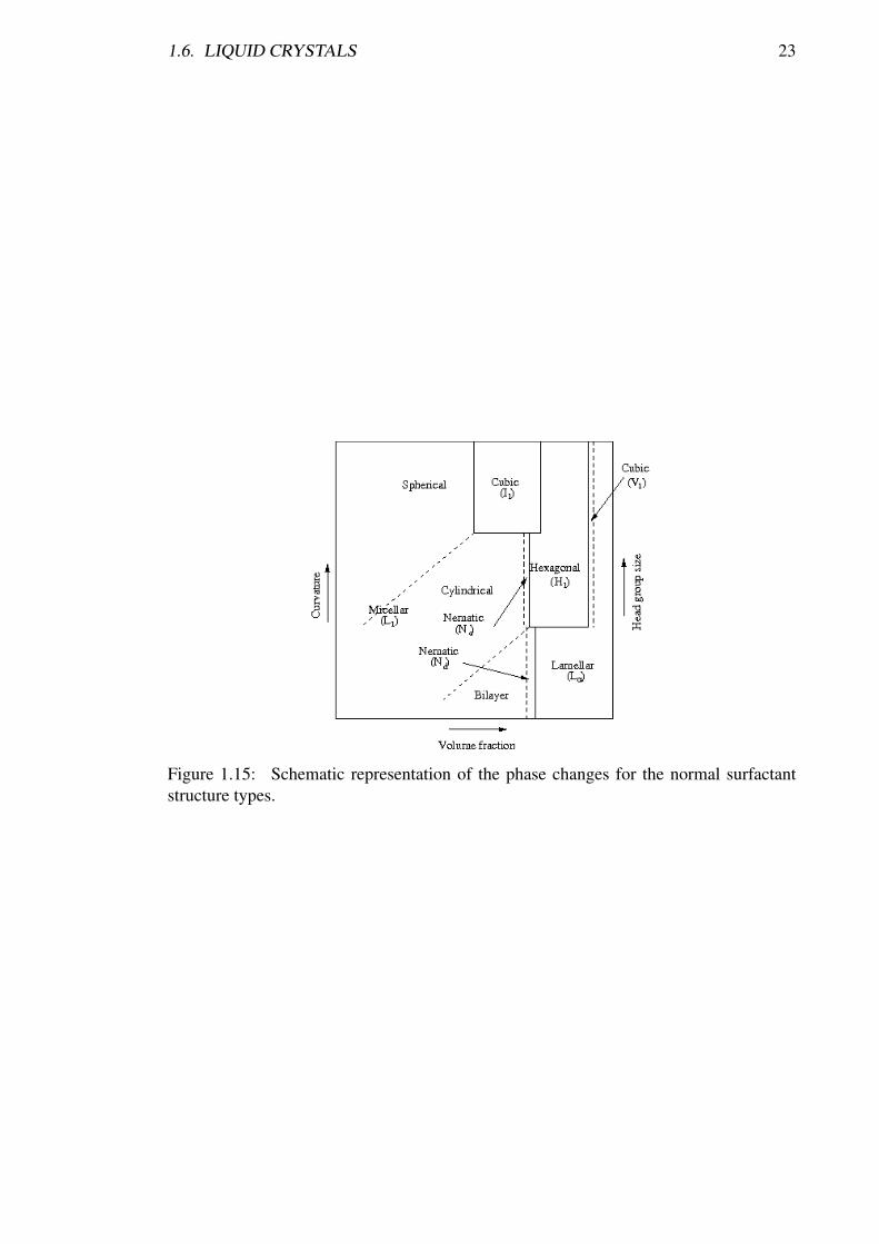
As mentioned in Section 1.4.2 the micelle shape is determined by the molecular struc-ture of the surfactants. However, there is a critical volume fraction (i.e. concentration) ofsurfactant above which these individual micelles cannot be supported. This leads to thedisordered solutions (micellar solutions) becoming ordered (liquid crystals). In addition,there is a maximum volume fraction of ordered micelles before they cannot fit together;e.g. spheres and cylinders cannot be packed together, no matter how tight, to totally fill avolume. (The existence of the micellar cubic phase also depends on the size and stabilityof the micelles. Micelles with a large energy barrier to size change will tend to increasein number rather than in size, which encourages packing of the micelles. However, if thestable micelle size is small there will be a large entropic barrier to overcome to form anordered micellar structure, which will encourage the disordered solution to prevail until ahigher concentration favours a larger aggregate phase, e.g. hexagonal or lamellar.) Whenall the available volume is occupied for a given shape, then the only way more surfactantcan be accommodated is with a change of structure towards less curvature [37]. For thenormal surfactant structure types these phase changes can be summarised by Figure 1.15(modified from Mitchell et al. (1983) [37]).
In the phase diagram not all the phases may take part: e.g. the nematic and bicontin-uous cubic phases may not occur, and there also may be added intermediate phases thatare in a similar region to the bicontinuous cubic phase. The gel phase may exist in thelamellar region at lower temperatures.
The sequence for the reversed phase surfactant structures is much more complicatedthan for the normal phases due to less radius limitations on micellar shapes; water on theinside could swell almost indefinitely until packing limits are reached. This means thatthese phase changes are not yet understood in terms of the surfactant structure [3].
1.6. LIQUID CRYSTALS 23
Figure 1.15: Schematic representation of the phase changes for the normal surfactantstructure types.

24 CHAPTER 1. REVIEW OF SOFT MATTER SYSTEMS
Table1.3:
Smectic
phases.
Group
AB
CD
EF
GH
IJ
KL
SideM
oleculesarrange
ina
micellartype
shapeand
thenpack
intoa
bodycentred
cubicphase
Plan

1.6. LIQUID CRYSTALS 25
Table 1.4: Notations used for the common phases.
Phase structure NotationLamellar LαHexagonal H1
Reversed hexagonal H2
Micellar cubic I1
Reversed micellar cubic I2
Bicontinuous cubic V1
Reversed bicontinuous cubic V2
Nematic NCylindrical Nematic Nc
Discotic Nematic ND
Chiral Nematic N*Smectic SChiral smectic C C*Gel LβMicellar L1
Reversed micellar L2
Sponge phase L3
Reversed sponge phase L4
Vesicular VMicroemulsion LWater W

26 CHAPTER 1. REVIEW OF SOFT MATTER SYSTEMS
1.7 References[1] American Institute of Physics. http://www.aip.org/dbis/stories/2007/17141.html,
last access 10/02/2008.
[2] K. Holmberg, B. Jönsson, B. Kronberg, and B. Lindman. Surfactants and Polymersin Aqueous Solution. John Wiley & Sons, Chichester, England, 2nd edition, 2007.
[3] S. Hussan, W. Rowe, and G. J. T. Tiddy. Handbook of Applied Surface and ColloidChemistry, chapter 21, pages 465–508. John Wiley & Sons, Chichester, England,2001.
[4] D. Fennell Evans and H. Wennerström. The Colloidal Domain - Where Physics,Chemistry, Biology and Technology meet. Wiley-VCH, New York, 1999.
[5] J. N. Israelachvili, D. J. Mitchell, and B. W. Ninham. Theory of Self-Assemblyof Hydrocarbon Amphiphiles into Micelles and Bilayers. Journal of the ChemicalSociety - Faraday Transactions II, 72:1525–1568, 1976.
[6] G. C. Shearman, O. Ces, R. H. Templer, and J. M. Seddon. Inverse LyotropicPhases of Lipids and Membrane Curvature. Journal of Physics: Condensed Matter,18:S1105–S1124, 2006.
[7] J. Israelachvili. Intermolecular and Surface forces. Academic Press, London, 2ndedition, 1992.
[8] C. Tanford. Micelle Shape and Size. Journal of Physical Chemistry, 73:3020–3024,1972.
[9] F. Reiss-Husson and V. Luzzati. The Structure of the Micellar Solutions of SomeAmphiphilic Compounds in Pure Water as Determined by Absolute Small-AngleX-Ray Scattering Techniques. Journal of Physical Chemistry, 68:3504–3511, 1964.
[10] K. S. Birdi. Self-assembly Monolayer Structures of Lipids and Macromolecules atInterfaces. Kluwer Academic, 1999.
[11] A. Bondi. van der Waals Volumes and Radii. Journal of Physical Chemistry,68:441–451, 1964.
[12] B. Lindman and H. Wennerström. Amphiphile aggregation in aqueous solution.Topics in Current Chemistry, 87:1–83, 1980.
[13] A. El-Hamouz. Effect of Surfactant Concentration and Operating Temperature onthe Drop Size Distribution of Silicon Oil Water Dispersion. Journal of DispersionScience and Technology, 28:797–804, 2007.
[14] R. Zana, W. Binana-Limbelé, N. Kamenka, and B. Lindman.Ethyl(hydroxyethyl)cellulose-Cationic Surfactant Interactions: Electrical Conduc-tivity, Self-Diffusion, and Time-Resolved Fluorescence Quenching Investigations.Journal of Physical Chemistry, 96:5461–5465, 1992.
[15] S. Miyagishi, H. Kurimoto, Y. Ishihara, and T. Asakawa. Determination of the Criti-cal Micelle Concentration and Microviscosity with a Fluorescence Probe, Auramine.Bulletin of the Chemical Society of Japan, 67:2398–2402, 1994.
1.7. REFERENCES 27
[16] J. A. Rego, J. A. A. Harvey, A. L. MacKinnon, and E. Gatdula. Asymmetric Synthe-sis of a Highly Soluble ’Trimeric’ Analogue of the Chiral Nematic Liquid CrystalTwist Agent Merck S1011. Liquid crystals, 37:37–43, 2010.
[17] L. A. Madsen, T. J. Dingemans, M. Nakata, and E. T. Samulski. ThermotropicBiaxial Liquid Crystals. Physical Review Letters, 92:145505, 2004.
[18] J. A. Castellano, editor. Liquid Gold: The Story of Liquid Crystal Displays and theCreation of an Industry. World Scientific Publishing.
[19] P. G. de Gennes and J. Prost, editors. The Physics of Liquid Crystals. OxfordClaredon Press, 1993.
[20] S. K. Ghosh. A Model for the Orientational Order in Liquid Crystals. Il NuovoCimento D, 4:229, 1984.
[21] P. J. Collings and M. Hird, editors. Introduction to Liquid Crystals. Taylor & Fran-cis, 1997.
[22] V. I. Kopp, B. Fan, H. K. M. Vithana, and A. Z. Genack. Low Threshold Lasingat the Edge of a Photonic Stop Band in Cholesteric Liquid Crystals. Opt. Letters,23:1707–1709, 1998.
[23] I. Dierking, editor. Textures of Liquid Crystals. Wiley-VCH, 2003.
[24] H. J. Coles and M. N. Pivnenko. Liquid Crystal ’Blue Phases’ with a Wide Temper-ature Range. Nature, 436:997–1000, 2005.
[25] D. Demus, J. W. Goodby, G. W. Gray, H. W. Spiess, and V. Vill, editors. Handbookof Liquid Crystals. Wiley-VCH, 1998.
[26] G. Pelzl, S. Diele, and W. Weissflog. Advanced Materials, 11:707, 1999.
[27] K. Lorenz, D. Holter, B. Stuhn, R. Mulhaupt, and H. Frey. Advanced Materials,8:414, 1996.
[28] F. Vogtle, S. Gestermann, R. Hesse, H. Schwierz, and B. Windisch. Progress inColloid and Polymer Science, 25:987, 2000.
[29] M. Makai, E. Csányi, I. Dékány, Z. Németh, and I. Erös. Structural Propertiesof Nonionic Surfactant/Glycerol/Paraffin Lyotropic Liquid Crystals. Colloid andPolymer Science, 281:839–844, 2003.
[30] K. Fontell. Cubic Phases in Surfactant and Surfactant-like Lipid Systems. Colloidand Polymer Science, 268:264–285, 1990.
[31] P. Sakya, J. M. Seddon, R. H. Templer, R. J. Mirkin, and G. J. T. Tiddy. MicellarCubic Phases and Their Structural Relationships: The Nonionic Surfactant SystemC12EO12/Water. Langmuir, 13:3706 – 3714, 1997.
[32] B. Lühmann, H. Finkelmann, and G. Rehage. Phase Behaviour and Structure ofPolymer Surfactants in Aqueous Solution. The Occurrence of Lyotropic Phases.Makromolekulare Chemie, 186:1059–1073, 1985.

28 CHAPTER 1. REVIEW OF SOFT MATTER SYSTEMS
[33] D. Chapman, R. M. Williams, and B. D. Ladbrooke. Physical Studies of Phos-pholipids. VI. Thermotropic and Lyotropic Mesomorphism of some 1,2-Diacyl-Phosphatidylcholines (Lecithins). Chemistry and Physics of Lipids, 1:445–475,1967.
[34] K. Larsson. Structure of Mesomorphic Phases and Micelles in Aqueous GlycerideSystems. Zeitschrift fur Physikalische Chemie, 56:173–198, 1967.
[35] J. M. Vincent and A. Skoulios. “Gel” and “Coagel.” I. Detection. Localization ina Phase Diagram and Determination of the “Gel” Structure of Potassium Stearate.Acta Crystallographica, 20:432–440, 1966.
[36] M. C. Holmes. Intermediate Phases of Surfactant-Water Mixtures. Current Opinionin Colloid and Interface Science, 3:485–492, 1998.
[37] D. J. Mitchell, G. J. T. Tiddy, L. Waring, T. Bostock, and M. P. McDonald. PhaseBehaviour of Polyoxyethylene Surfactants: Mesophase Structures and Partial Mis-cibility (Cloud Points). Journal of the Chemical Society: Faraday Transactions,79:975–1000, 1983.