review of residential comfort control products …...pnnl-27141 review of residential comfort...
TRANSCRIPT

PNNL-27141
Review of Residential Comfort Control Products and Opportunities
December 2017
CE Metzger
S Goyal
MC Baechler


PNNL-27141
Review of Residential Comfort Control Products and Opportunities
CE Metzger
S Goyal
MC Baechler
December 2017
Prepared for
the U.S. Department of Energy
under Contract DE-AC05-76RL01830
Pacific Northwest National Laboratory
Richland, Washington 99352


iii
Executive Summary
Buildings consume about 40% of total energy used in the United States, and residential buildings account
for more than half of the energy consumed in buildings.
Researchers have shown that about 60% of heating, ventilation, and air-conditioning (HVAC) systems
have installation, commissioning, and performance problems, leading to as much as a 30% increase in
annual energy consumption (Lstiburek 2010; Domanski 2014). The efficient design and improved
operation of HVAC systems in homes could lead to significant energy reduction.
The development of commercially available sensors and control-related software in the past decade has
resulted in a rapidly growing and changing HVAC control industry. Several papers describe parts of the
HVAC controls space (Maasoumy, 2016, DOE 2016b, DOE 2016d, Wang and Goins, 2015). However,
the objective of this paper is to fill a remaining need to help researchers capture a snapshot of HVAC
control product capabilities and remaining opportunities that save homeowners and technicians’ time,
money, and energy. By developing a taxonomy around the interaction between HVAC sensor and control
technology, the current state-of-the-art product capabilities can be organized and summarized.
This paper begins by discussing the interaction of each major component in advanced sensor and control
applications related to HVAC equipment. Figure ES.1 shows how each of these components interacts
with each other to form appropriate inputs and outputs for a given application.
Figure ES.1. Interactions between Several Component Technologies in an HVAC Control System (blue
lines represent communication.)
The paper also looks at the applications of these components to commissioning, maintenance, and
operations of the HVAC equipment in residential buildings. This paper assumes that commissioning is
Actuators
Data
Storage
and
External Signals
Human-
in-the-loop
Sensors
Computation Platform
Control Applications

iv
conducted by the same contractor who installed the HVAC system (or possibly by a third-party verifier).
Scheduled maintenance, or retro-commissioning, are also included in this section. An overview of major
commissioning applications—including the current state-of-the-art, the benefit of improving that current
technology, and the possible missed opportunities associated with each application—is shown in
Figure ES.2.
Figure ES.2. An Overview of State-of-art, Technical Gaps, and Benefits of Commissioning Applications
Maintenance is likely performed by an HVAC contractor. This is usually initiated by the homeowner,
although some homeowners opt for a service contract providing biannual inspections and tune ups. A
summary of the major maintenance applications is shown in Figure ES.3.

v
Figure ES.3. An Overview of State-of-art, Technical Gaps, and Benefits of Maintenance Applications
vi
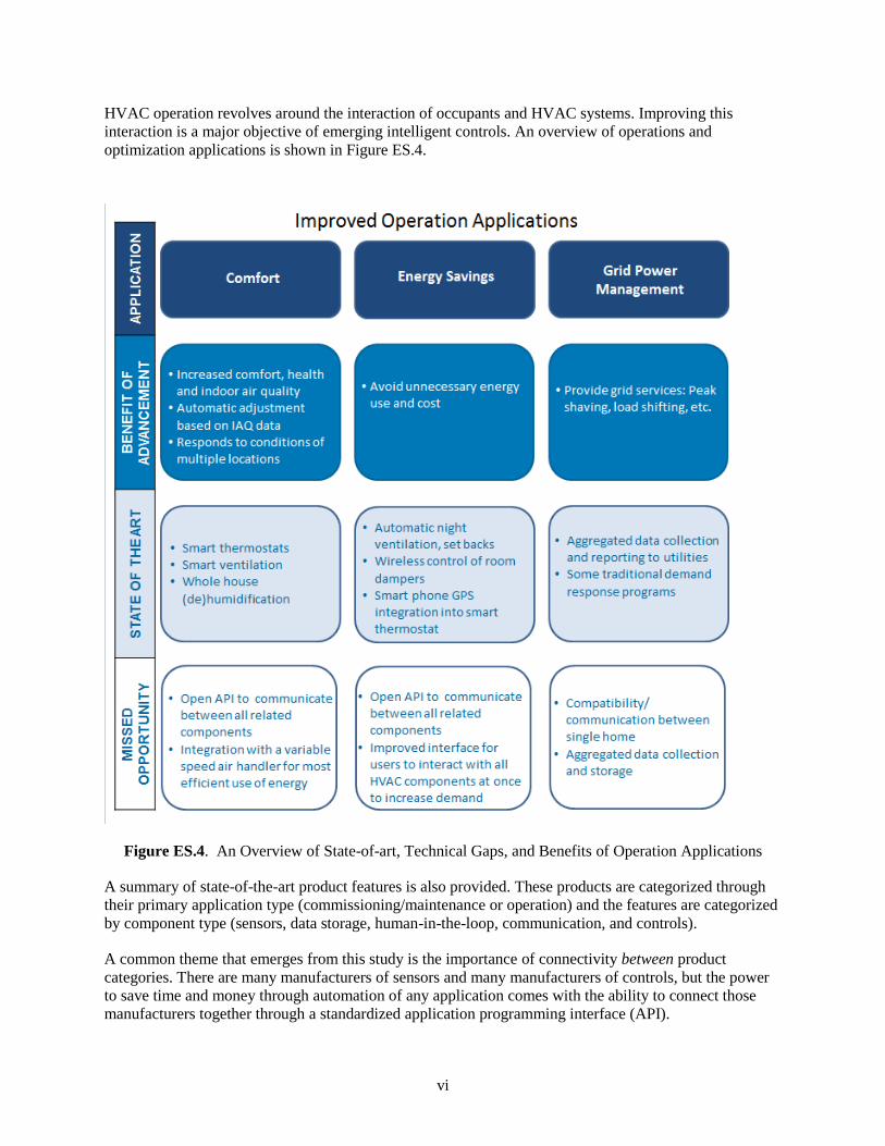
HVAC operation revolves around the interaction of occupants and HVAC systems. Improving this
interaction is a major objective of emerging intelligent controls. An overview of operations and
optimization applications is shown in Figure ES.4.
Figure ES.4. An Overview of State-of-art, Technical Gaps, and Benefits of Operation Applications
A summary of state-of-the-art product features is also provided. These products are categorized through
their primary application type (commissioning/maintenance or operation) and the features are categorized
by component type (sensors, data storage, human-in-the-loop, communication, and controls).
A common theme that emerges from this study is the importance of connectivity between product
categories. There are many manufacturers of sensors and many manufacturers of controls, but the power
to save time and money through automation of any application comes with the ability to connect those
manufacturers together through a standardized application programming interface (API).

vii
Two reoccurring opportunities to help save energy also appear throughout the paper. First, the use and
control of variable speed motors throughout many components of the HVAC system would help take
advantage of opportunities where full power is not necessary. Second, permanent and internet-connected
sensors could help quickly diagnose and alert homeowners and technicians of non-optimal operating
conditions so they can be remedied (e.g., dirty filters).


ix
Acknowledgments
This paper would not have been possible without funding from the U.S. Department of Energy’s Building
America Program. The authors acknowledge and thank Eric Werling and Lena Burkett from the U.S.
Department of Energy for their enthusiastic management of the Building America Program as well as
their invaluable dedication to this paper. The authors also gratefully acknowledge help from Rosemarie
Bartlett, Michael Brambley, Joshua Butzbaugh, Paul Ehrlich, Cory Fox, and Nora Wang for providing
relevant information and excellent reviews.


xi
Acronyms and Abbreviations
API application programming interface
ASHRAE American Society of Heating, Refrigerating and Air-Conditioning Engineers
BTU British thermal unit(s)
CO carbon monoxide
CO2 carbon dioxide
EPA U.S. Environmental Protection Agency
ERV energy recovery ventilation
FDD fault detection and diagnostics
GPS Global Positioning System
HRV heat recovery ventilation
HSRS HVAC Smart Relay Switch
HVAC heating, ventilation, and air-conditioning
IAQ indoor air quality
IFTTT If This Then That
kWh kilowatt-hour(s)
NA not applicable
PIR passive infrared
PM particulate matter
RECS Residential Energy Consumption Survey
RH relative humidity
UV ultraviolet
VFD variable frequency drive
VOC volatile organic compounds


xiii
Contents
Executive Summary ..................................................................................................................................... iii
Acknowledgments ........................................................................................................................................ ix
Acronyms and Abbreviations ...................................................................................................................... xi
1.0 Introduction .......................................................................................................................................... 1
2.0 State-of-the-Art Component Technologies ........................................................................................... 3
2.1 Sensors ......................................................................................................................................... 3
2.2 Data Storage and External Signals ............................................................................................... 6
2.3 Human-in-the-Loop ...................................................................................................................... 6
2.4 Communication between Components ......................................................................................... 7
2.5 Computation, Controllers and Actuators ...................................................................................... 7
2.5.1 Smart/Intelligent Controllers and Actuators ...................................................................... 8
2.6 Integrated Sensors and Controls ................................................................................................... 8
3.0 State-of-the-Art and Advanced Applications ....................................................................................... 9
3.1 Commissioning ............................................................................................................................ 9
3.1.1 Verifying Basic Functionality ......................................................................................... 10
3.1.2 Duct Leakage and Air Flow ............................................................................................ 11
3.1.3 Refrigerant Charge .......................................................................................................... 12
3.2 Maintenance ............................................................................................................................... 13
3.2.1 Verifying Basic Functionality ......................................................................................... 14
3.2.2 Refrigerant Level ............................................................................................................. 15
3.2.3 Air Filter Replacement .................................................................................................... 15
3.2.4 Less Common Faults ....................................................................................................... 16
3.3 Improved Operation ................................................................................................................... 17
3.3.1 Operation Applications Focused on Comfort .................................................................. 18
3.3.2 Operation Applications Focused on Energy Savings ...................................................... 19
3.3.3 Operation Applications Focused on Grid Services Integration ....................................... 22
4.0 Summary of State-of-the-Art Product Features .................................................................................. 23
5.0 Remaining Technical and Market Opportunities ................................................................................ 31
5.1 Sensors ....................................................................................................................................... 31
5.2 Data Storage and External Signals ............................................................................................. 31
5.3 Human-in-the-Loop .................................................................................................................... 32
5.4 Communication between Components ....................................................................................... 32
5.4.1 Opportunities for Refrigerant Sensor Communication .................................................... 33
5.4.2 Automated System Zoning .............................................................................................. 34
5.4.3 Opportunities for Ductless Mini-split Communication with Central Systems ................ 34
5.5 Computation, Controllers and Actuators .................................................................................... 34

xiv
5.6 Market Barriers .......................................................................................................................... 35
6.0 References .......................................................................................................................................... 37

xv
Figures
ES.1 Interactions between Several Component Technologies in an HVAC Control System .................... iii
ES.2 An Overview of State-of-art, Technical Gaps, and Benefits of Commissioning Applications .......... iv
ES.3 An Overview of State-of-art, Technical Gaps, and Benefits of Maintenance Applications ............... v
ES.4 An Overview of State-of-art, Technical Gaps, and Benefits of Operation Applications ................... vi
1 U.S. Energy Consumption by Sector and End Usage ......................................................................... 1
2 Outline of Paper .................................................................................................................................. 2
3 Interactions between Several Components in an HVAC Control System .......................................... 3
4 An Overview of State-of-art, Technical Gaps, and Benefits of Commissioning Applications ......... 10
5 An Overview of State-of-art, Technical Gaps, and Benefits of Maintenance Applications ............. 14
6 Summary of Improved Operation Applications ................................................................................ 17
Tables
1 Advantages, Disadvantages, and Applications of Several Types of Sensors ...................................... 4
2 Actuation Parameters Used for Controlling the HVAC Systems ........................................................ 7
3 Remaining Opportunities to Reduce Time, Cost and Human Error Associated with Verifying the
Basic Functionality of HVAC Systems ............................................................................................. 11
4 Remaining Opportunities to Reduce Time and Cost Associated with Measuring Duct Leakage and
Air Flow ............................................................................................................................................ 12
5 Remaining Opportunities to Reduce Time, Cost and Human Error Associated with Charging
Refrigerant......................................................................................................................................... 13
6 Remaining Opportunities to Reduce Time and Cost Associated with Checking and Changing the
Refrigerant Level .............................................................................................................................. 15
7 Remaining Opportunities to Reduce Time and Cost Associated with Air Flow Issues in HVAC
Systems ............................................................................................................................................. 16
8 Missed Opportunities to Improve IAQ while Minimizing Energy Use ............................................ 18
9 Missed Opportunities to Save Energy Associated with (De)Humidification .................................... 19
10 Missed Opportunities to Save Energy with Natural Heating and Cooling ........................................ 20
11 Remaining Opportunities to Save Time and Cost When Installing Multi-Zone Systems ................. 21
12 Remaining Opportunities for Complete HVAC Optimization for Energy Reduction, Health, and
Comfort ............................................................................................................................................. 21
13 Examples of Commissioning and Maintenance Refrigerant-Related Product Capabilities .............. 23
14 Examples of Air-Side Commissioning and Maintenance Product Capabilities ................................ 25
15 Examples of Advanced Thermostat (Operation) Product Capabilities ............................................. 26
16 Examples of Indoor Air Quality (Operation) Product Capabilities ................................................... 28
17 Examples of Other Advanced Operation Products and Product Capabilities ................................... 29


1
1.0 Introduction
Buildings are one of the major energy consumers across the world. In the United States, they contribute
approximately 40% to the total energy consumption (EIA 2015). According to the Residential Energy
Consumption Survey (EIA 2009), residential buildings account for more than half of the energy
consumed in buildings.
Figure 1 shows the total energy consumption in the United States by end-use sector and the energy
consumption in homes by their end usage. As shown in the figure, heating and cooling consume about
48% of the energy usage in residential buildings. A small percentage of energy savings in the residential
heating, ventilation, and air-conditioning (HVAC) systems can have high economic and environmental
impacts.
a) Energy Consumption by End-use Sector b) Energy Consumption in Residential Buildings by End
Usage
Figure 1. U.S. Energy Consumption by Sector and End Usage (EIA 2015 and EIA 2009)
To date, the majority of HVAC system sales have been replacement units that moved through a single
distribution channel (EERE 2011). The manufacturer designs and builds the HVAC equipment, sells it to
a distributor, who sells it to an HVAC contractor, who installs the unit for the end consumer. HVAC
controls, such as thermostats and programmable thermostats, have typically been installed concurrently
with the rest of the HVAC system. Now, more and more of these control devices are available at retail
stores. This gives consumers more choices and pushes manufacturers to provide features that are valuable
(e.g., saving time, money, or energy) for consumers.
Researchers have shown that about 60% of HVAC systems have installation, commissioning, and
performance problems, leading to as much as a 30% increase in annual energy consumption (Lstiburek
2010; Domanski 2014). The efficient design and improved operation of HVAC systems in homes could
lead to significant energy reduction. (As of 2015, there were approximately135 million households in the
United States (EIA 2015), and the average annual electricity consumption for a U.S. residential customer
is about 12,000 kWh. If 60% of homes in the U.S. were wasting 30% of their HVAC energy on
performance issues that could be fixed with fault detection and diagnostics (FDD), about 146 billon kWh
or 0.5 quads could be saved overall with better HVAC controls.)
While seven manufacturers (UTC/Carrier, Goodman/Amana, Trane/American Standard, Lennox, Rheem,
York, and Nordyne) dominate the HVAC equipment market, they are not the market leaders in external
HVAC controls. This disconnect between the equipment and controls manufacturers has left the market
disjointed and flooded with options for consumers.

2
The objective of this paper is to capture a snapshot in time for this fast-moving industry. This paper will
identify the current state-of-the-art sensing and control technologies, applications, and products. With this
information and a review of recent literature, remaining opportunities to save homeowners and
technicians time, cost, and energy are summarized. Although this paper touches on connected buildings
and the “Internet of Things,” it does not provide a comprehensive review of those industries as some other
review papers do (Maasoumy, 2016, DOE 2016b, DOE 2016d, Wang and Goins, 2015). This paper is
different from other review papers because it focuses solely on potential advancements in residential
HVAC control applications.
The organization of the paper is shown in Figure 2. It shows the topic for each section and indicates what
question each section is attempting to answer. Section 2.0 reviews the existing state-of-the-art sensors and
controls/actuators, communication strategies, computation platforms, and interfaces related to residential
HVAC systems. A description of advanced sensing and control applications is presented in Section 3.0.
Section 4.0 presents a national energy savings impacts assessment and market barriers evaluation of the
applications and associated technologies. Section 5.0 quantifies the potential impact of each technology
advancement on the overall energy use of U.S. housing stock and prioritizes gaps based on these
estimates.
Figure 2. Outline of Paper
Section 5: Missed Opportunities and Market Barriers
What are some opportunities beyond the current available products?
Section 4: Summary of Product Capabilities
What product features are available today?
Section 3: State-of-the-Art and Advanced Applications
How can the application of sensor and control technology be improved?
Section 2: State-of-the-Art Component Technologies
What are the basic components of sensor and control technologies?

3
2.0 State-of-the-Art Component Technologies
A successful control system for implementing a basic or advanced control application may include up to
six major components: (1) sensors, (2) data storage and external signals, (3) human-in-the-loop, (4)
communication between components, (5) computation platform with control applications, and (6)
actuators. Figure 3 shows interactions between these components.
Figure 3. Interactions between Several Components in an HVAC Control System (Blue lines represent
communication.)
2.1 Sensors
Sensors are devices used to produce electrical, digital, or optical signals to measure physical parameters
and detect environmental events. Over the past few decades, the sensor and communications market has
grown significantly with the development of temperature, humidity, occupancy, light, and CO2 sensors.
However, use of these sensors for HVAC control has still not reached its maximum potential in
residential buildings for four main reasons: (1) high cost, which can be due to a combination of equipment
expense, installation, and maintenance; (2) lack of computational capabilities; (3) inability of HVAC
systems to effectively use the data from the sensors; and (4) the need to have sensors at multiple
locations. Note that in Table 1 the sensors are listed at the component level. Multiple sensors (along with
communication sensors) can be combined together to create products that are of potential use for HVAC
systems. Such products are described later in the section. Table 1 provides an overview of available
sensors that are either used in existing residential HVAC systems or that are capable of being used in the
HVAC systems.
Actuators
Data
Storage
and
External Signals
Human-
in-the-loop
Sensors
Computation Platform
Control Applications

4
On-board sensors and diagnostics are common in HVAC equipment. However, those systems tend to be
proprietary, and ultimately help diagnose internal issues with the equipment. Usually, this type of fault
helps the equipment be capable of running at all. This paper goes above and beyond the baseline
functioning of the system and focuses on ways in which external sensors and controls can help
homeowners and technicians save time, money and energy. Therefore, on-board sensors will not be
discussed further in this paper.
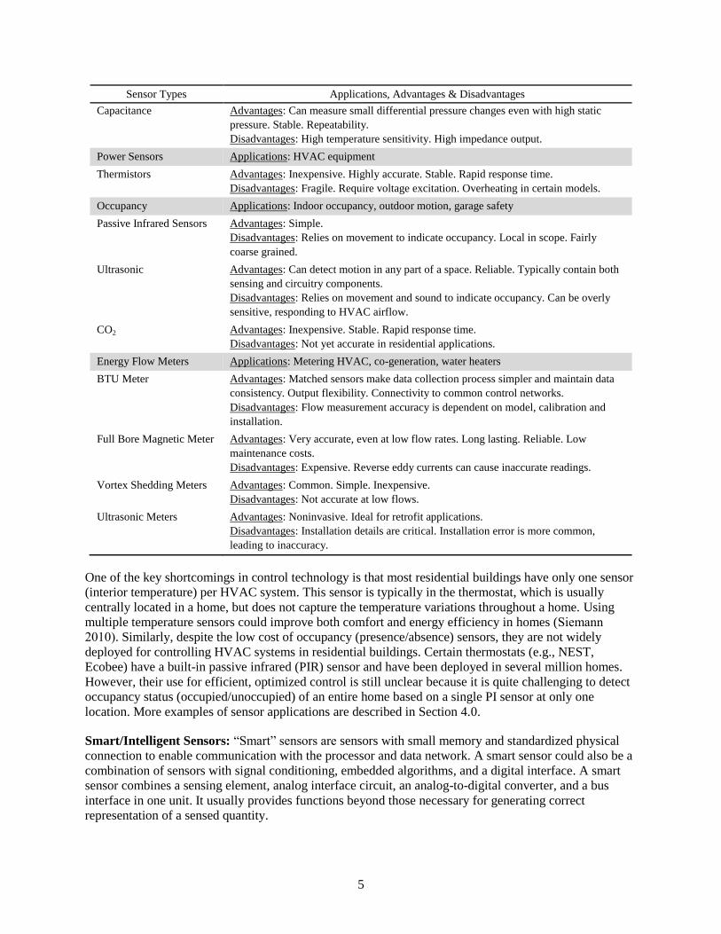
Table 1. Advantages, Disadvantages, and Applications of Several Types of Sensors
Sensor Types Applications, Advantages & Disadvantages
Temperature Applications: Outdoor, rooms, ducts
Thermocouples Advantages: Inexpensive. Simple. Self-powered. Large temperature range. Rapid
response time. Durable.
Disadvantages: Not very accurate or stable. Signal conditioner needed.
Thermistors Advantages: Inexpensive. Highly accurate. Stable. Rapid response time.
Disadvantages: Fragile. Require voltage excitation. Overheating in certain models.
Resistance-temperature
devices (RTDs)
Advantages: Long lasting. Accurate. Very stable. Easy to recalibrate.
Disadvantages: Expensive. Slower response time. Require current excitation.
Humidity Applications: Outdoor, dew point, rooms
Resistive Relative
Humidity Sensor
Advantages: Small size. Low cost. Long-term stability. Field interchangeable.
Disadvantages: Accuracy is inadequate at low relative humidity RH values. Can shift
values if exposed to condensation. Significant temperature dependencies. Exposure to
chemical vapors will lead to premature failure.
Capacitance Relative
Humidity Sensor
Advantages: Stable. Resistant to chemical vapors.
Disadvantages: Accuracy decreases as temperature deviates from calibration
temperature. Field interchangeability requires computer-based recalibration for many
models. Distance between sensing element and signal conditioning circuitry is limited
to <10 feet. Selection of sensor and transmitter combination is important for proper
application.
Thermal Conductivity
Absolute Humidity
Sensor
Advantages: Very durable. Resistant to chemical vapors.
Disadvantages: Accuracy is dependent on ambient temperature. Respond to any gas
that has thermal properties different from those of dry nitrogen.
Air Quality Applications: Rooms, ducts
Photoionization Detectors
(PIDs)
Advantages: Accurate. Reliable. Immediate. Can detect multiple types of volatile
organic compounds (VOCs). Portable or permanent installation. Can log data.
Disadvantages: More expensive than other indoor air quality (IAQ) sensor types.
Infrared Carbon Dioxide
Monitors
Advantages: Portable or permanent installation.
Disadvantages: Acts as a secondary measurement tool for IAQ because CO2 is an
indicator of poor IAQ, not a contaminant. Does not measure VOCs from building
materials, furniture, and contamination.
Metal Oxide Sensors
(MOS)
Advantages: Simple. Inexpensive. Can detect multiple types of VOCs.
Disadvantages: Limited sensitivity. Slower to react. False positives in response to
moisture or temperature.
Air Pressure Applications: Ducts
Variable Resistance
Transducers
Advantages: Simple. Inexpensive. Accurate. Reliable. Durable. Repeatability.
Disadvantages: Amplifier is needed to amplify and condition signal to prevent
interference. Changes in temperature may necessitate recalibration.
5
Sensor Types Applications, Advantages & Disadvantages
Capacitance Advantages: Can measure small differential pressure changes even with high static
pressure. Stable. Repeatability.
Disadvantages: High temperature sensitivity. High impedance output.
Power Sensors Applications: HVAC equipment
Thermistors Advantages: Inexpensive. Highly accurate. Stable. Rapid response time.
Disadvantages: Fragile. Require voltage excitation. Overheating in certain models.
Occupancy Applications: Indoor occupancy, outdoor motion, garage safety
Passive Infrared Sensors Advantages: Simple.
Disadvantages: Relies on movement to indicate occupancy. Local in scope. Fairly
coarse grained.
Ultrasonic Advantages: Can detect motion in any part of a space. Reliable. Typically contain both
sensing and circuitry components.
Disadvantages: Relies on movement and sound to indicate occupancy. Can be overly
sensitive, responding to HVAC airflow.
CO2 Advantages: Inexpensive. Stable. Rapid response time.
Disadvantages: Not yet accurate in residential applications.
Energy Flow Meters Applications: Metering HVAC, co-generation, water heaters
BTU Meter Advantages: Matched sensors make data collection process simpler and maintain data
consistency. Output flexibility. Connectivity to common control networks.
Disadvantages: Flow measurement accuracy is dependent on model, calibration and
installation.
Full Bore Magnetic Meter Advantages: Very accurate, even at low flow rates. Long lasting. Reliable. Low
maintenance costs.
Disadvantages: Expensive. Reverse eddy currents can cause inaccurate readings.
Vortex Shedding Meters Advantages: Common. Simple. Inexpensive.
Disadvantages: Not accurate at low flows.
Ultrasonic Meters Advantages: Noninvasive. Ideal for retrofit applications.
Disadvantages: Installation details are critical. Installation error is more common,
leading to inaccuracy.
One of the key shortcomings in control technology is that most residential buildings have only one sensor
(interior temperature) per HVAC system. This sensor is typically in the thermostat, which is usually
centrally located in a home, but does not capture the temperature variations throughout a home. Using
multiple temperature sensors could improve both comfort and energy efficiency in homes (Siemann
2010). Similarly, despite the low cost of occupancy (presence/absence) sensors, they are not widely
deployed for controlling HVAC systems in residential buildings. Certain thermostats (e.g., NEST,
Ecobee) have a built-in passive infrared (PIR) sensor and have been deployed in several million homes.
However, their use for efficient, optimized control is still unclear because it is quite challenging to detect
occupancy status (occupied/unoccupied) of an entire home based on a single PI sensor at only one
location. More examples of sensor applications are described in Section 4.0.
Smart/Intelligent Sensors: “Smart” sensors are sensors with small memory and standardized physical
connection to enable communication with the processor and data network. A smart sensor could also be a
combination of sensors with signal conditioning, embedded algorithms, and a digital interface. A smart
sensor combines a sensing element, analog interface circuit, an analog-to-digital converter, and a bus
interface in one unit. It usually provides functions beyond those necessary for generating correct
representation of a sensed quantity.
6
Examples of smart sensors that are currently available include digital thermometer with thermocouple
probes, multi-meter, infrared sensor/temperature gun, thermo-hygrometer, thermal-imaging temperature
gun, and refrigerant pressure gauge. Examples of products that contain smart sensors include iManifold,
Comfort Guard, AirAdvice, and FooBot. These products are discussed in more detail in Section 4.0.
2.2 Data Storage and External Signals
Data storage plays a key role in verifying, validating, and improving the commissioning, maintenance,
and operation of an HVAC system. Historical data can be processed to learn user behavior and adapt
control algorithms accordingly to deliver energy-efficient solutions that improve thermal comfort and
IAQ inside homes. There are three options for storing data: (1) on the cloud over the internet, (2) on an
on-board device as a part of the existing control system (e.g., smart thermostat), and (3) on a local device
that is connected to the existing equipment controllers or thermostats, but not considered to be a necessary
part to operate the system (e.g., local gateways and servers).
Several services and products that store data on the cloud are available in the market (e.g., Oracles,
Opower). However, these products do not use the stored data for active control purposes; instead they
focus on monitoring, diagnostics, and other services that identify potential energy saving measures.
Although some devices, like smart thermostats (discussed further in Section 2.6), offer on-board data
storage and a little computational power for local control purposes, only some thermostats and some
cloudstorage providers offer open interface to access data and control functions. If the connection
between these devices is open and easily accessible, the computational power and storage capacity of the
entire control system can be significantly increased.
External data signals (e.g., utility pricing, weather, incentive signals) can be considered valuable inputs
when deciding the control actions for the HVAC system. If This Then That (IFTTT) is an example of an
application that can send external signals to computation platforms like smart thermostats. More use cases
for data storage and external signals are discussed further in Section 3.0 of this paper.
Many of the technologies described in this paper incorporate connectedness with the web or the cloud.
Consumers may view this connectivity as introducing risk to devices that formerly had none. A report
from the California Energy Commission (Ghansah 2012) highlights a few cyber security and privacy
issues that are possible by using current programmable communication thermostats and advanced
metering infrastructure. The need for cyber security is not exhaustively described in this paper because
the issue is ancillary to the actual control functions and applications. However, this need is so
fundamental that it is included in the final set of recommendations included in Chapter 5.0.
2.3 Human-in-the-Loop
Human-in-the-loop is the term this paper uses to describe any user’s interaction (e.g., occupants, HVAC
technicians, utility operators, etc.) providing input or receiving output from the computation platform.
The interface for this interaction can be mechanical (e.g., a physical dial), digital (e.g., a computer
screen), or internet-based (e.g., a phone application, tablet, etc.).
One example of a human-in-the-loop is an application that notifies the homeowner when a filter needs to
be replaced (e.g., FilterScan). There are also interfaces that a utility control center could use to inform
operators of peak events and manipulate many residential HVAC systems at once (e.g., Opower). Those
interfaces would likely be part of a much more complex software program for demand response
(Somasundaram et al. 2014). These systems could also include third-party vendors that gather data and

7
have a control capability, but offer control services to either a utility or to the consumer (Baechler and
Hao 2016).
An example of a human-in-the-loop interface that did not deliver its full potential benefit was the
programmable thermostat. According to the Energy Information Administration’s 2009 Residential
Energy Consumption Survey (EIA 2009), 43% of heating systems and 48% of cooling systems in
residential buildings use a programmable thermostat to control them. Unfortunately, many of the
programmable thermostats that have been installed are not properly operated. Of the consumers who own
a programmable thermostat, many struggle to properly understand or program its functions. A recent
study by Callaway et al. (2014) indicates that programmable thermostats are difficult for users to
understand, which has led to ineffective usage or even abandonment. Due to misuse, households with
programmable thermostats sometimes have higher HVAC energy consumption on average than those
with manual controls. As a result of this finding, the U.S. Environmental Protection Agency (EPA)
suspended the ENERGY STAR programmable thermostat program in 2009. The ENERGY STAR
program has since initiated a label for certified “smart thermostats” that are proven to save energy
compared to a typical thermostat1.
2.4 Communication Between Components
Communication functions allow data transfer between sensors, actuators, controllers, processors, storage,
and user interfaces/devices. Communication between these sensors and controls can either be hard-wired,
or wireless (local or through the internet). In the direct hard-wired case, a sensor is physically connected
using a metal wire, which usually transmits a voltage or current signal, through a computation platform,
to a control device and/or actuator. In the local wireless option, sensor data are sent to a control device
and/or actuator using a local wireless network. Both the sensor and the control device are required to have
a wireless relay installed and configured (e.g., Bluetooth). The internet is not needed in this case. In the
internet wireless option, sensor data are transmitted to a control device and/or actuator over the internet.
Both sensors and control devices are required to have a wireless sensor installed and be connected to the
internet. In this case, the data is usually routed to the device through a server, which can be relatively
slow and less reliable compared to any hard-wired connection.
2.5 Computation, Controllers and Actuators
Controls change system operation using both software and hardware. Software receives data from
sensors, performs computations, and sends a signal to other external sources. Hardware physically
responds to a stimulus control signal. Most control hardware is in the form of an actuator. Historically
residential HVAC control systems operated using binary (on/off) actuation. Many newer systems support
variable capacity outputs for evaporator and condenser fans as well as for gas burners and compressors.
The movement to variable capacity has increased both comfort and efficiency. Common actuators are
described in Table 2.
Table 2. Actuation Parameters Used for Controlling the HVAC Systems
Actuation Parameters(a)
Description
Cooling on/off
A binary signal is sent to turn on or off the cooling mode of operation. This
parameter is usually available for both automatic and manual control in most
existing systems.
1 https://www.energystar.gov/products/heating_cooling/smart_thermostats/key_product_criteria

8
Actuation Parameters(a)
Description
Heating on/off
A binary signal is sent to turn on or off the heating mode of operation. This
parameter is usually available for both automatic and manual control in most
existing systems.
Fan on/off The fan is turned on or off, which can be independent of the heating/cooling mode of
operation.
Damper position The damper position is manipulated to change airflow rate in different rooms of a
building. This is not usually prevalent in existing systems.
Fan speed The fan speed can be adjusted in systems with electronically commutated motors to
change the total supply airflow rate.
Compressor speed The compressor speed can be changed in HVAC units with inverter driven
compressors.
Refrigerant outlet
temperature
The outlet temperature of refrigerant is changed, which is achieved by changing the
outdoor blower speed or compressor speed.
(a) Actuation parameters can be changed automatically or manually (by a technician or consumer) during the
commissioning, FDD, operation, maintenance, or control stages.
2.5.1 Smart/Intelligent Controllers and Actuators
Smart controllers and actuation devices typically have wider flexibility than traditional controllers and
actuators. These devices are capable of integrating themselves easily into HVAC systems (or their smart
sensors or intelligent sensing devices) to provide better performance. Examples of smart controllers
include variable vent flow devices (e.g., Ecovent), variable speed fans (e.g., Concept 3 motor), and multi-
stage refrigeration units (e.g., Carrier’s Infinity® 18VS Heat Pump 25VNA8). Details of these products
are discussed further in Section 4.0.
2.6 Integrated Sensors and Controls
Integrated sensors and controls are devices consisting of a combination of sensors and controls that
physically receive a signal, do some type of computation, and send a signal to the HVAC equipment. An
example of a simple integrated sensor and control is a thermostat (basic, programmable, or smart).
A thermostat receives data (mostly room temperature) from sensors and sends an actuation signal to
operate the HVAC equipment. Basic thermostats are traditional electrical/mechanical devices that
measure temperature and control the on/off state of an HVAC system. Programmable thermostats are
digital electronic thermostats with an ability to switch between temperature set points based on the time of
day (e.g., unoccupied hours during weekdays) or day of the week (e.g., weekends) as set by the user.
Connected thermostats offer enhanced communication, improved interface, and simplified schedule
setting (DOE 2016b). Smart thermostats are a type of connected thermostat that contain computation
features, and thus are capable of supporting advanced software tools to monitor system performance,
detect faults, and ensure correct installation and operation. Smart thermostats (a.k.a learning thermostats,)
offer enhanced sensing/communication/computation features, and thus are capable to support advanced
software tools to monitor system performance, detect faults, and ensure correct installation and operation.
As compared to traditional or programmable thermostats, smart thermostats offer users much more
flexibility in the development and implementation of advanced control strategies.
9
3.0 State-of-the-Art and Advanced Applications
In the previous section, components including sensors, data storage, human-in-the-loop, computation
platforms, and controls/actuators were each discussed individually. This section describes integrated
applications made up of multiple components that provide a service to an end user. These applications are
divided into three use-case categories: commissioning, maintenance, and improved operation. In
residential buildings, commissioning is likely conducted by the same contractor who installed the HVAC
system, or possibly a third-party verifier. This step is sometimes performed as part of the installation.
Commissioning can also be performed on existing HVAC systems and equipment, which is referred to as
retro-commissioning. An HVAC contractor likely performs maintenance, which is usually initiated by the
homeowner, although some homeowners opt for a service contract providing biannual inspections and
tune ups. Operation of the system revolves around occupants, and improving this interaction between the
occupant and the HVAC system is the subject of Section 3.3. In the future, there would ideally be
products that perform tasks across all three categories.
Advanced FDD methods discussed in the sections below can detect faults and prevent catastrophic
failures before they happen, thereby saving energy and money while increasing occupant comfort and
maximizing the lifespan of the equipment. Advanced controls can use sensor data to operate a system at
its optimal performance level based on system specifications, user inputs, and surrounding conditions.
Moreover, stored data can also be used to inform and educate occupants and contractors about system
operation and design weaknesses, which may result in improved performance by altering the system
design or upgrading the system components.
3.1 Commissioning
HVAC commissioning ensures that the installed performance and operation of each component of the
HVAC system meet the desired specifications outlined in construction documentation. Ensuring a proper
installation requires the following: (1) sensors to measure airflow rate, refrigerant level, refrigerant
temperature, zone temperature, etc.; (2) a computation platform to collect the sensors’ data and perform
calculations; and (3) a software to process the data and indicate whether the system is installed and
configured correctly. These three components together are sometimes referred to as FDD.
Commissioning applications discussed in this section of the report focus on times when an HVAC
technician would already be coming to a home, either for initial installation, or for scheduled maintenance
(a.k.a. retro-commissioning).
An overview of major commissioning applications, including the current state-of-the-art, the benefit of
improving that current technology and the major gaps associated with each application are show in
Figure 4.
The detailed analysis of each major application is described in more detail in the subsections below. The
tables that discuss the technology gaps of each application include a description of the state-of-the-art
technology, potential technology advancements, and a summary of technology gaps. Each table also
refers to “inputs,” which include all inputs that help the application complete its task. These can include
sensor measurements, manual input/inspection, or stored data from the cloud. The “outputs” refer to all of
the outputs that the application provides. These can include a control action, a user notification, or even
data sent to the cloud.

10
Figure 4. An Overview of State-of-art, Technical Gaps, and Benefits of Commissioning Applications
3.1.1 Verifying Basic Functionality
In residential buildings, the basic functions of an HVAC system are typically checked by the onsite
technician who is installing the system. Checking the basic functionality of the system typically requires a
person to turn the system and thermostat on, and visually inspects each of the components. Some of the
items a technician would check to ensure basic functionality include: system turns on/off, is each
component generally functioning (compressor, fan, burners, sensors, etc.), thermostat signal from
equipment. Specific measurements that are taken to determine if there is a fault in the system include:
power flowing to equipment, power flowing between equipment components, refrigerant charge, air flow,
and connectivity between components. Current state-of-the-art processes and potential technologies are
listed in Table 3 below.

11
Table 3. Remaining Opportunities to Reduce Time, Cost and Human Error Associated with Verifying
the Basic Functionality of HVAC Systems
Description Inputs Output
Current State-of-the-Art
HVAC system
on/off
Visual inspection NA
Components
functioning
Manual temperature
measurement at grills, on-board
diagnostics.
NA
Thermostat on/off Visual inspection NA
Thermostat settings NA NA
Potential Technology
HVAC system
on/off
Wireless detection of HVAC
system
Notification sent to
contractor if HVAC
equipment is undetectable.
Components
functioning
Current transducers throughout
system and temperature sensors.
Notification sent to
contractor if any power or
temperature measurements
are out of range.
Thermostat on/off Wireless detection of thermostat Notification sent to
contractor if thermostat is
undetectable.
Thermostat settings Wireless timestamp capability.
Smart algorithm to determine
HVAC type based on signal, or
additional current transmitter
sensor.
Notification sent to
contractor if HVAC type is
undetectable.
Remaining Opportunity
Internet-connected current transducers and temperature sensors for remote access of
data. Open application programming interface (API) for product connectivity to save
time and reduce overall cost.
3.1.2 Duct Leakage and Air Flow
In this application, we first focus on the air flow rate side of the system, which is divided into three parts:
(1) detecting any leakage through the duct (and possibly sealing the leakage), (2) ensuring that air flow
supplied to a home is close to its designed value, and (3) ensuring that the air flow is well distributed to
different parts of the home.
Duct leakage is typically tested using a duct blaster device (e.g., Minneapolis Duct Blaster®). Once
leakage is detected in the ductwork, it can be sealed using Aeroseal, which detects small holes and seals
them without manual labor for each hole, or more traditional methods if the ducts are accessible. This
process is already fairly automated and there are no further controls-related advancements for this
particular commissioning application.
For air balancing and total air flow commissioning, an HVAC contractor will typically use a magnehelic
gauge with two static pressure probes to test air flow rate near the air handler. A calculation is then
conducted to convert the pressure difference into an airflow measurement. A flow hood (e.g., Alnor Flow
Hood) that is typically used for measuring the air flow at each register can also be used on the return side
to measure the whole-building airflow, but this is not common practice. Variable speed fans can enhance
the ability to make automatic changes in the operation if enough air is not supplied to the home.
Balancing air flow rate should primarily be accomplished through good house layout and ductwork
design. That said, there is some balancing that can occur through the tuning of grills or manual dampers.
There is potential for automatic air balancing and grill tuning using products that are on the market today;
12
however, those products have not been tested by a third party and have not been developed for this
specific purpose. Although, more expensive, true multi-zone systems can provide pressure and damper
position measurements, which can be used to detect and correct slight balancing issues as well.
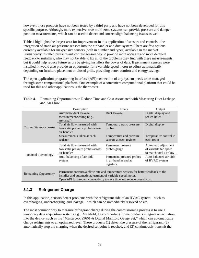
Table 4 highlights the largest area for improvement in this application of sensors and controls - the
integration of static air pressure sensors into the air handler and duct system. There are few options
currently available for inexpensive sensors (both in number and types) available in the market.
Permanently installed pressure/airflow rate sensors would provide more accurate and more detailed
feedback to installers, who may not be able to fix all of the problems they find with these measurements,
but it could help reduce future errors by giving installers the power of data. If permanent sensors were
installed, it would also provide an opportunity for a variable speed motor to adjust automatically
depending on furniture placement or closed grills, providing better comfort and energy savings.
The open application programming interface (API) connection of any system needs to be managed
through some computational platform. One example of a convenient computational platform that could be
used for this and other applications is the thermostat.
Table 4. Remaining Opportunities to Reduce Time and Cost Associated with Measuring Duct Leakage
and Air Flow
Description Inputs Output
Current State-of-the-Art
Automatic duct leakage
measurement/sealing (e.g.,
Aeroseal)
Duct leakage Digital display and
sealed holes
Total air flow measured with
two static pressure probes across
air handler
Temporary static pressure
probes
Digital display
Measurements taken at each
register
Temperature and pressure
sensors at each register
Temperature control in
each room
Potential Technology
Total air flow measured with
two static pressure probes across
air handler
Permanent pressure
probes/gauge
Automatic adjustment
of variable fan speed
to match total air flow
Auto-balancing of air-side
system
Permanent pressure probes
in air handler and at
registers
Auto-balanced air-side
of HVAC system
Remaining Opportunity Permanent pressure/airflow rate and temperature sensors for better feedback to the
installer and automatic adjustment of variable speed motor.
Open API for product connectivity to save time and reduce overall cost
3.1.3 Refrigerant Charge
In this application, sensors detect problems with the refrigerant side of an HVAC system—such as
overcharging, undercharging, and leakage—which can be immediately resolved onsite.
The most common way to measure refrigerant charge during the commissioning process is to use a
temporary data acquisition system (e.g., iManifold, Testo, Sporlan). Some products integrate an actuation
into the device, such as the “Mastercool 99661-A Digital Manifold Gauge Set,” which can automatically
charge refrigerants to an optimized level. These products (1) detect the pressure of the refrigerant, (2)
automatically stop the charging when the desired set point is reached, and (3) continuously transmit the

13
information to a digital display (wired or wireless) or to the technician’s smart phone or tablet during the
entire process.
The potential technology described in Table 5 includes a set of permanent manufacturer-installed sensors
in the outdoor unit of a system that uses refrigerant. The benefit of permanent sensors and chargers is that
it could save time and money for future applications. Internet connectivity of sensors like this would
provide an opportunity for remote quality assurance.
Table 5. Remaining Opportunities to Reduce Time, Cost and Human Error Associated with Charging
Refrigerant
Description Inputs Output
Current State-of-the-Art
Temporary data collection
and automatic shutoff of
charging system (e.g.,
Mastercool 99661)
Refrigerant temperature and
pressure
Digital display, auto-
shutoff when desired
pressure is reached
Potential Technology
Permanent sensor
installation with automatic
flow shutoff when fully
charged
Refrigerant temperature and
pressure
Digital display, auto-
shutoff when desired
pressure is reached
Remaining Opportunity
Permanent refrigerant gauge and charger to capitalize on opportunity and save money
for future use. Internet connectivity of sensors like this would provide an opportunity
for remote quality assurance.
3.2 Maintenance
Maintenance is necessary to ensure the ongoing performance of HVAC systems, equipment, and related
components. Preventative maintenance (a.k.a. retro-commissioning) focuses on tune ups or other actions
that are based on a timeline, rather than a physical trigger or fault. Reactive maintenance is based on a
physical measurement or fault that signals that something is not performing as it should. Herein, reactive
maintenance is referred to simply as maintenance in this report.
As discussed in Section 3.1, FDD can be used to identify, isolate, and correct or avoid faults that develop
over time in existing HVAC systems. Although there is overlap between preventative maintenance and
reactive maintenance, this section focuses on reactive maintenance, where permanently installed (and
internet-connected) sensors could help reduce the time and cost associated with unexpected HVAC faults.
An overview of major maintenance applications, including the current state-of-the-art, the benefit of
improving that current technology, and the major gaps associated with each application is shown in
Figure 5. The detailed analysis of each major application is described in more detail in the subsections
below.

14
Figure 5. An Overview of State-of-art, Technical Gaps, and Benefits of Maintenance Applications
3.2.1 Verifying Basic Functionality
The basic functionality of the system can be monitored and corrected using the same approach as is
discussed in Section 3.1. In this case, data storage may be a helpful addition to the gaps previously
mentioned. Data storage either locally or on the cloud could help determine if measurements are changing
over time. This type of data could help detect a faulty sensor/sensor drift or even a dying motor.
In case of faulty sensors, an appropriate action (alert, control action, etc.) can be taken to compensate for
inaccurate sensors so that the system performance is minimally affected. Examples include removing a
faulty sensor from control system architecture, and changing the temperature set point if the humidity or
temperature sensor is offset by a known value. Other applications include checking thermostat
15
settings/parameters, data reporting, and verifying the sequence of operations and control functionalities.
The requirements and potential advancements are similar to the ones discussed in Section 3.1.
3.2.2 Refrigerant Level
This application is similar to the “refrigerant charge” application described in Section 3.1. The refrigerant
level is a key factor in HVAC performance and energy efficiency. This includes overcharging,
undercharging, and leakage over time.
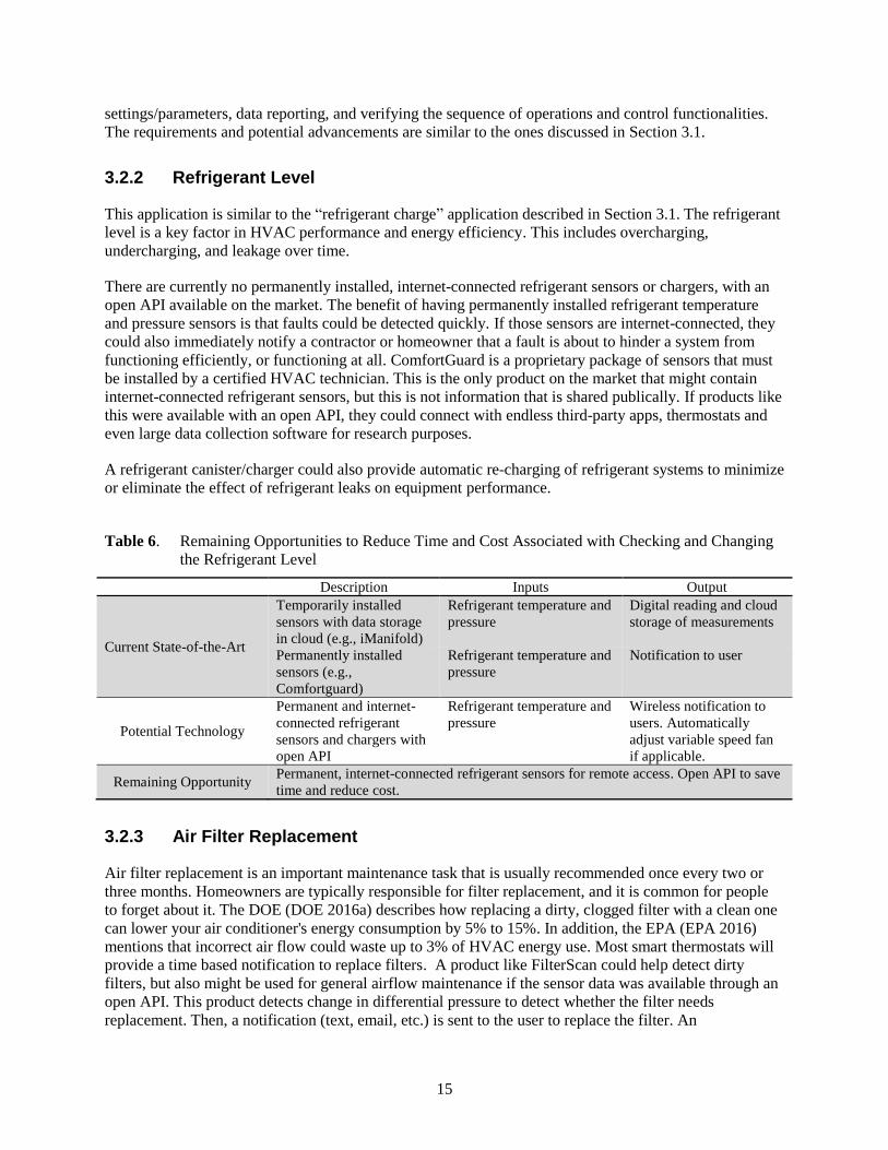
There are currently no permanently installed, internet-connected refrigerant sensors or chargers, with an
open API available on the market. The benefit of having permanently installed refrigerant temperature
and pressure sensors is that faults could be detected quickly. If those sensors are internet-connected, they
could also immediately notify a contractor or homeowner that a fault is about to hinder a system from
functioning efficiently, or functioning at all. ComfortGuard is a proprietary package of sensors that must
be installed by a certified HVAC technician. This is the only product on the market that might contain
internet-connected refrigerant sensors, but this is not information that is shared publically. If products like
this were available with an open API, they could connect with endless third-party apps, thermostats and
even large data collection software for research purposes.
A refrigerant canister/charger could also provide automatic re-charging of refrigerant systems to minimize
or eliminate the effect of refrigerant leaks on equipment performance.
Table 6. Remaining Opportunities to Reduce Time and Cost Associated with Checking and Changing
the Refrigerant Level
Description Inputs Output
Current State-of-the-Art
Temporarily installed
sensors with data storage
in cloud (e.g., iManifold)
Refrigerant temperature and
pressure
Digital reading and cloud
storage of measurements
Permanently installed
sensors (e.g.,
Comfortguard)
Refrigerant temperature and
pressure
Notification to user
Potential Technology
Permanent and internet-
connected refrigerant
sensors and chargers with
open API
Refrigerant temperature and
pressure
Wireless notification to
users. Automatically
adjust variable speed fan
if applicable.
Remaining Opportunity Permanent, internet-connected refrigerant sensors for remote access. Open API to save
time and reduce cost.
3.2.3 Air Filter Replacement
Air filter replacement is an important maintenance task that is usually recommended once every two or
three months. Homeowners are typically responsible for filter replacement, and it is common for people
to forget about it. The DOE (DOE 2016a) describes how replacing a dirty, clogged filter with a clean one
can lower your air conditioner's energy consumption by 5% to 15%. In addition, the EPA (EPA 2016)
mentions that incorrect air flow could waste up to 3% of HVAC energy use. Most smart thermostats will
provide a time based notification to replace filters. A product like FilterScan could help detect dirty
filters, but also might be used for general airflow maintenance if the sensor data was available through an
open API. This product detects change in differential pressure to detect whether the filter needs
replacement. Then, a notification (text, email, etc.) is sent to the user to replace the filter. An
16
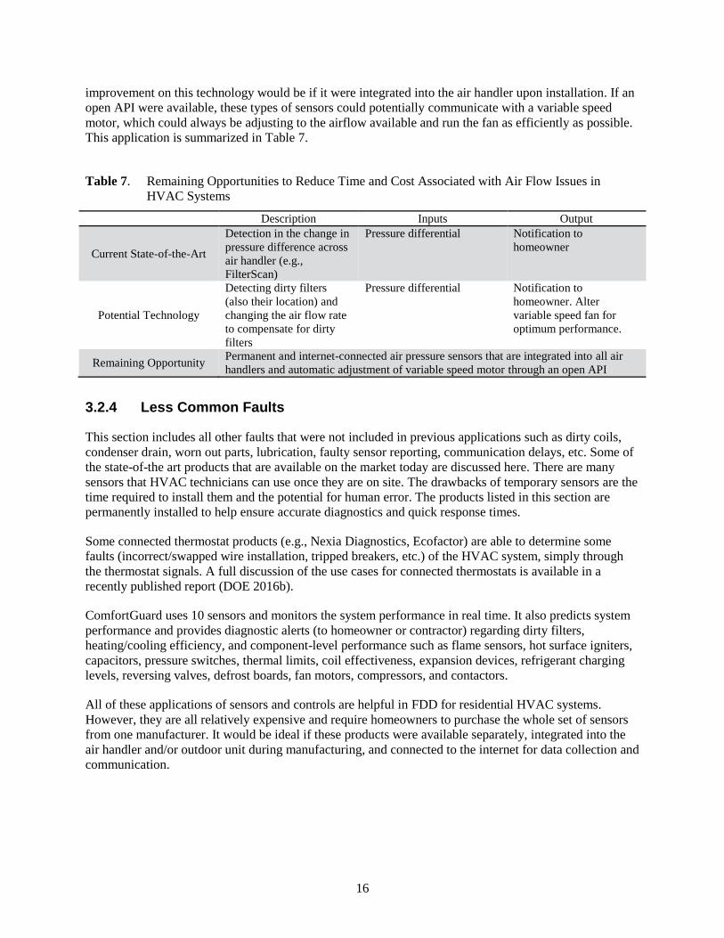
improvement on this technology would be if it were integrated into the air handler upon installation. If an
open API were available, these types of sensors could potentially communicate with a variable speed
motor, which could always be adjusting to the airflow available and run the fan as efficiently as possible.
This application is summarized in Table 7.
Table 7. Remaining Opportunities to Reduce Time and Cost Associated with Air Flow Issues in
HVAC Systems
Description Inputs Output
Current State-of-the-Art
Detection in the change in
pressure difference across
air handler (e.g.,
FilterScan)
Pressure differential Notification to
homeowner
Potential Technology
Detecting dirty filters
(also their location) and
changing the air flow rate
to compensate for dirty
filters
Pressure differential Notification to
homeowner. Alter
variable speed fan for
optimum performance.
Remaining Opportunity Permanent and internet-connected air pressure sensors that are integrated into all air
handlers and automatic adjustment of variable speed motor through an open API
3.2.4 Less Common Faults
This section includes all other faults that were not included in previous applications such as dirty coils,
condenser drain, worn out parts, lubrication, faulty sensor reporting, communication delays, etc. Some of
the state-of-the art products that are available on the market today are discussed here. There are many
sensors that HVAC technicians can use once they are on site. The drawbacks of temporary sensors are the
time required to install them and the potential for human error. The products listed in this section are
permanently installed to help ensure accurate diagnostics and quick response times.
Some connected thermostat products (e.g., Nexia Diagnostics, Ecofactor) are able to determine some
faults (incorrect/swapped wire installation, tripped breakers, etc.) of the HVAC system, simply through
the thermostat signals. A full discussion of the use cases for connected thermostats is available in a
recently published report (DOE 2016b).
ComfortGuard uses 10 sensors and monitors the system performance in real time. It also predicts system
performance and provides diagnostic alerts (to homeowner or contractor) regarding dirty filters,
heating/cooling efficiency, and component-level performance such as flame sensors, hot surface igniters,
capacitors, pressure switches, thermal limits, coil effectiveness, expansion devices, refrigerant charging
levels, reversing valves, defrost boards, fan motors, compressors, and contactors.
All of these applications of sensors and controls are helpful in FDD for residential HVAC systems.
However, they are all relatively expensive and require homeowners to purchase the whole set of sensors
from one manufacturer. It would be ideal if these products were available separately, integrated into the
air handler and/or outdoor unit during manufacturing, and connected to the internet for data collection and
communication.

17
3.3 Improved Operation
An HVAC system is operational if it is correctly responding to a thermostat and delivering air within
manufacturer specifications. Basic HVAC performance can be improved upon in three ways: (1) comfort,
(2) energy savings, and (3) grid power management.
The sub-topics below are divided into these three improvement categories, although, many of the sub-
topics could apply to multiple improvement areas. For example, applications in the energy savings group
are primarily focused on reducing energy consumption although they may also lead to improved comfort.
An overview of major improved operation applications, including the current state-of-the-art, the benefit
of improving that current technology, and the major gaps associated with each application is shown in
Figure 6. The detailed analysis of each major application is described in more detail in the subsections
below.
Figure 6. Summary of Improved Operation Applications

18
3.3.1 Operation Applications Focused on Comfort
3.3.1.1 Temperature Set Point
Thermostats provide temperature set point control. Basic thermostats measure temperature and use a
manually input set point (analog or digital) to send a “turn on” or “turn off” command to the HVAC
system. Programmable thermostats have the ability to change temperature set point based on a pre-
defined user-input schedule. Connected thermostats offer enhanced communication, improved interface,
and simplified schedule setting (DOE 2016b). Smart thermostats are a type of connected thermostat that
contain computation features, and thus are capable of supporting advanced software tools to monitor
system performance, detect faults, and ensure correct installation and operation.
Smart thermostats offer the most advanced way of controlling the indoor temperature. With smart
thermostats, the temperature set point can be optimally controlled based on occupant behavior, outside
temperature, historical set points, energy cost, or utility signals. The optimal set point can be calculated
over the cloud or using the computational power available on the device. Depending on control
algorithms, measurements from several sensors and data from users may be needed. The combination of
two-way communication, data collection, and modeling human behavior has made these devices a
platform for vendors to offer demand-response services to utilities (Baechler and Hao 2016).
Smart thermostats (e.g., NEST, Ecobee, etc.) are currently the state-of-the-art application of temperature
set point control. EnergyStar has added a smart thermostat category1, which can help identify a certain
level of energy savings that can be expected from some thermostats. However, other than this Energy Star
distinction, the amount of comfort gained and energy saved across the spectrum of smart thermostats
available is different and currently cannot be easily compared.
3.3.1.2 Ventilation, Filtration and Indoor Air Quality
Ventilation provides fresh outdoor air to the spaces inside buildings. The primary function of ventilation
control is to adjust the airflow (determined by standards like ASHRAE 62.2) entering or exiting a
building. Inputs into this control task can be as simple as the time of day, or can be based on factors such
as CO2 measurements, outdoor temperature/humidity, and occupancy. Filtration can occur with or without
ventilation and typically uses physical barriers to minimize particulates in the air that is circulated
throughout a home. Both of these mechanisms can be associated with better IAQ (Singer et al., 2017).
Table 8 focuses on how ventilation and filtration can be used to optimize IAQ and energy use.
Table 8. Missed Opportunities to Improve IAQ while Minimizing Energy Use
Description Inputs Output
Current State-of-the-Art
ERV/HRV(a)
Time of day, manual On/off state of motor
Whole house air
purification
NA, Ultraviolet (UV) light
always on
UV light
IAQ sensors that have
open API and can control
a thermostat (e.g., Foobot)
CO2, VOCs, PM, CO,
temperature, humidity
Air handler on/off state,
and user notification
Potential Technology
Smart ventilation:
optimizing input from
IAQ sensors to control
Formaldehyde, PM, CO2,
CO, VOCs, outdoor
conditions, number of
Automatically changes
ventilation rate and turn
on/off filtration system;
1 https://www.energystar.gov/productfinder/product/certified-connected-thermostats/results

19
Description Inputs Output
ventilation and filtration
system (perhaps at
variable rates)
occupants user notifications
Remaining Opportunity
Smart ventilation integrated with filtration system. Integration with a variable speed
air handler through an open API would provide opportunities for energy savings by
matching air flow rate to pollutant level.
(a) ERV and HRV are energy recovery ventilation and heat recovery ventilation, respectively.
Smart ventilation is gaining momentum in research and in industry. The goal of some smart ventilation
systems is to save up to 40% of ventilation related energy use (Walker, 2014). However, a major gap is
the ability to control ventilation rates in all types of ventilation systems, using some of the same sensors
that are used for other applications (but that may use proprietary communication protocols).
3.3.1.3 Humidity
As homes continue to have a lower and lower HVAC load, humidity becomes a more and more important
factor to address directly (Brown et al., 2013). State-of-the-art humidity control devices can be integrated
into the main air handler unit in a home. These humidifiers and dehumidifiers provide the ability to meet
a certain humidity set point that is set by the user at the thermostat (or in a thermostat app).
Humidification and dehumidification are energy intensive processes due to the phase change of the liquid
to vapor or vice versa. Therefore, any opportunity to save energy during this process should be capitalized
on. Table 9 describes the missed opportunities to save energy when humidifying or dehumidifying a
home.
Table 9. Missed Opportunities to Save Energy Associated with (De)Humidification
Description Inputs Output
Current State-of-the-Art
Whole house
(de)humidification
Temperature and humidity Opens/closes water valve,
or turns on the compressor
and dehumidification
blower set point to meet
humidity set point
Potential Technology
Variable rate
(de)humidification
with open API
Indoor and outdoor humidity
and occupancy sensors that
detect number of people or
activity level
Changes valve position,
compressor and blower
speeds to meet humidity set
point
Remaining Opportunity
Variable rate (de)humidification could react to indoor and outdoor conditions and
deliver ideal humidity levels with the least amount of energy use. Open API would
enable connection to existing or third-party occupancy sensors or other measurements.
3.3.2 Operation Applications Focused on Energy Savings
3.3.2.1 Natural Heating and Cooling
This application uses natural heating and cooling if outdoor weather conditions are favorable. Night
ventilation and operation of windows are two ways to accomplish natural heating and cooling in
residential buildings. To implement this application automatically, however, there are two major
requirements:

20
actual outdoor weather measurements and forecasts, which can be obtained using weather website
APIs or local weather stations/sensors that send data to the cloud
the ability of an HVAC system to allow natural heating or cooling, (e.g., supply/exhaust fan control,
outside damper control, automatic window control), which is not common in currently available
systems.
Table 10 shows the current state-of-the-art application and how it might be improved upon for the best
possible control of natural heating and cooling.
Table 10. Missed Opportunities to Save Energy with Natural Heating and Cooling
Description Inputs Output
Current State-of-the-Art
Automatic ventilation
based on favorable outdoor
air conditions (e.g.,
NightBreeze)
Outdoor temperature
and humidity
Opens/closes damper or and
turns fan on
Potential Technology
Fully integrated and
automated natural
ventilation with high
control options
Indoor and outdoor
temperature and
humidity
Changes damper position and
fan (exhaust, supply) speed
Opens/closes windows
Remaining Opportunity Automatic natural ventilation during favorable outdoor and indoor conditions using an
open API to connect to the main HVAC system.
3.3.2.2 Multi-Zone Temperature Distribution
In this application, different HVAC zones can be created and controlled independently by using
additional actuation sensors and hardware at multiple locations. More than 70% of residential buildings
use one thermostat (RECS 2009)1 and are not capable of controlling the environment in individual rooms
independently. Although most OEMs offer a multiple zone system, they are very expensive and typically
only practical in new construction. A less expensive implementation of a zoned system at a large scale
requires the following:
low-cost temperature/humidity sensors that can be easily integrated into existing HVAC system.
Some sensors that are available today can be connected to a thermostat through open API interfaces
like IFTTT, but the full integration with the thermostat to create a zoned home based on sensor
feedback has yet to be tested. These sensors currently cost $25-60 per sensor.
inexpensive diffusers or dampers to control the amount of air flow rate entering different rooms.
Although several commercial products (Ecovent, Keen Home Vent, etc.) are available for retrofitting
the exiting diffusers, the products are relatively new and only being deployed primarily to enhance
comfort.
development and implementation of control algorithms. Currently, smart diffusers control the damper
positions based on temperature set points, which can be set through occupant’s smart phone apps.
These apps have limited control commands based on mostly temperature settings in a home. More
advanced controls with multiple sensor inputs (e.g., occupancy and temperature) have not been tested.
To capitalize on the energy savings benefit related to multiple zones in a house, the air flow should be
dynamically adjusted according to the registers available. Reducing the fan speed lowers both the fan
1 Although more detailed questions about HVAC equipment have been added to the RECS database since 2009, the
question regarding the number of thermostats in a home was not reported on after 2009.

21
energy and heating/cooling energy consumption. Although there are commercially available products
with more than one fan speed (e.g., INFINITY 18VS heat pump 25VNA8, Goodman 3 Ton 16 SEER AC
Model DSXC160361 with Goodman Multi-Position Air Handler with Variable Speed Fan Model
AVPTC48D14), they are not prevalent in existing buildings. Therefore, in this application, air handler or
air handler motor replacement would be recommended (to enable variable speed) along with the multi-
zone control.
Improved comfort is also a benefit of this application. If a home experiences high temperature differences
between certain parts of the home, or has multiple stories, more uniform temperature distribution may be
possible with variable air flow rate supplied to each room.
Table 11 describes the current state-of-the-art multi-zone systems and what kind of product might be an
improvement on the state-of-the-art system.
Table 11. Remaining Opportunities to Save Time and Cost When Installing Multi-Zone Systems
Description Inputs Output
Current State-of-the-
Art
Wireless control of room
dampers based on varied
set points (e.g., KEEN),
retrofit solution
Temperature and
pressure
Varies damper position for each grill
Wired control of zone
dampers based on varied
set points (e.g., Honeywell
Wireless TrueZone), hard-
wired solution
Temperature Varies damper position for each zone
Potential Technology
Automated control of
dampers and air flow rate
using other sensors (e.g.,
occupancy)
Temperature, air
flow rate and
occupancy
Adjusts damper and fan speed
Remaining
Opportunity
Integration of multi-zone systems with other sensors and variable speed equipment with
open API.
3.3.2.3 Complete Smart HVAC Optimization for Energy Reduction, Health and Comfort
This application uses predictive and optimization control approaches to reduce energy consumption,
while maintaining IAQ and comfort in a specified range. Implementing this application requires much
higher computational power than other applications. Therefore, it is likely that all of the computation
would be performed on the cloud and the control actions can be sent through the internet. Depending on
the type of control approach, the application may need weather forecast, occupancy behavior, and other
models for predicting the system behavior and taking an appropriate action accordingly. This type of
system would include control over the entire environment of the home, including temperature, humidity,
multi-zoning, automatic shading, and mechanical and natural ventilation. Table 12 describes the current
components that exist for this type of system, as well as the remaining opportunities in this fully
integrated application.
Table 12. Remaining Opportunities for Complete HVAC Optimization for Energy Reduction, Health,
and Comfort
Description Inputs Output
Current State-of-the-Art Complete system from one CO2, VOCs, PM, CO, Controls temperature, humidity,

22
Description Inputs Output
company (e.g., Honeywell
Whole Home, Lennox
Complete iHarmony etc.)
occupancy,
temperature and
humidity
ventilation in a sort-of
independent fashion with
limited data exchange
Disjointed retrofit products
(e.g., Foobot, Ecovent,
smart phone, occupancy
sensors, smart thermostat,
Keen) that provide input to
different computation
platforms
CO2, VOCs, PM, CO,
occupancy,
temperature and
humidity
Separate control of HVAC
system components including
set back, multi-zoning,
automatic shading, mechanical
and natural ventilation.
Potential Technology
Integrated sensor products
that easily connect to a
central hub which can
optimize a complete HVAC
system
CO2, VOCs, PM, CO,
air flow, occupancy
and indoor/outdoor
temperature and
humidity
Optimized control HVAC
system including set back,
multi-zoning, mechanical and
natural ventilation.
Remaining Opportunity
Energy savings and comfort associated with a complete smart system. Ease of
connectivity and optimization between components and an improved user interface
would enable more people to use such a product.
3.3.3 Operation Applications Focused on Grid Services Integration
HVAC systems can be used to provide grid services, which may not necessarily result in reduced energy
consumption. There are several applications in this area: (1) integration and coordination of multiple
HVAC systems and other components at the community level, (2) enabling automated demand response
through individual HVAC system control, (3) using residential buildings as a micro-grid and coordinating
among the generation resources and loads inside residential buildings, (4) precooling to shift or shave the
peak load, (5) duty cycling the HVAC unit, and (6) deciding the time interval between on and off times
can be used for reducing peak load. All of these services can be provided through smart thermostats and
are available with the technology on the market today. Discussion of the use cases for smart thermostats is
available in a recently published report (DOE 2016b).
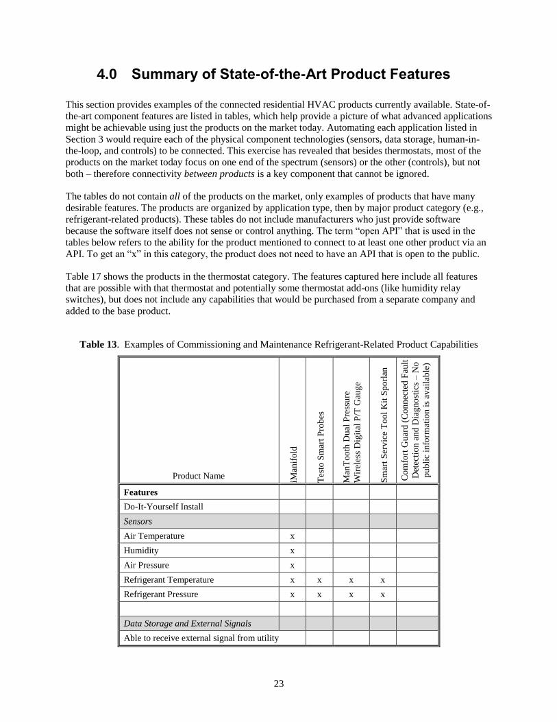
23
4.0 Summary of State-of-the-Art Product Features
This section provides examples of the connected residential HVAC products currently available. State-of-
the-art component features are listed in tables, which help provide a picture of what advanced applications
might be achievable using just the products on the market today. Automating each application listed in
Section 3 would require each of the physical component technologies (sensors, data storage, human-in-
the-loop, and controls) to be connected. This exercise has revealed that besides thermostats, most of the
products on the market today focus on one end of the spectrum (sensors) or the other (controls), but not
both – therefore connectivity between products is a key component that cannot be ignored.
The tables do not contain all of the products on the market, only examples of products that have many
desirable features. The products are organized by application type, then by major product category (e.g.,
refrigerant-related products). These tables do not include manufacturers who just provide software
because the software itself does not sense or control anything. The term “open API” that is used in the
tables below refers to the ability for the product mentioned to connect to at least one other product via an
API. To get an “x” in this category, the product does not need to have an API that is open to the public.
Table 17 shows the products in the thermostat category. The features captured here include all features
that are possible with that thermostat and potentially some thermostat add-ons (like humidity relay
switches), but does not include any capabilities that would be purchased from a separate company and
added to the base product.
Table 13. Examples of Commissioning and Maintenance Refrigerant-Related Product Capabilities
Product Name iMan
ifo
ld
Tes
to S
mar
t P
rob
es
Man
To
oth
Du
al P
ress
ure
Wir
eles
s D
igit
al P
/T G
aug
e
Sm
art
Ser
vic
e T
oo
l K
it S
po
rlan
Co
mfo
rt G
uar
d (
Co
nn
ecte
d F
ault
Det
ecti
on
an
d D
iag
no
stic
s –
No
pu
bli
c in
form
atio
n i
s av
aila
ble
)
Features
Do-It-Yourself Install
Sensors
Air Temperature x
Humidity x
Air Pressure x
Refrigerant Temperature x x x x
Refrigerant Pressure x x x x
Data Storage and External Signals
Able to receive external signal from utility

24
Product Name iMan
ifo
ld
Tes
to S
mar
t P
rob
es
Man
To
oth
Du
al P
ress
ure
Wir
eles
s D
igit
al P
/T G
aug
e
Sm
art
Ser
vic
e T
oo
l K
it S
po
rlan
Co
mfo
rt G
uar
d (
Co
nn
ecte
d F
ault
Det
ecti
on
an
d D
iag
no
stic
s –
No
pu
bli
c in
form
atio
n i
s av
aila
ble
)
On-board data storage
x
Cloud data storage x
Human-in-the-loop
User Programming
Automated Programming
Scheduled alerts
Automated alerts x
x
Communication Between Components
Wi-Fi
Bluetooth
x x x
Open API
ZigBee x
Controls
Heating/cooling on/off
Humidity level
Ventilation
Fan on/off
Damper position
Fan speed
Zone control

25
Table 14. Examples of Air-Side Commissioning and Maintenance Product Capabilities
Product Name Fil
terS
can
Ho
ney
wel
l V
enti
lati
on
Sy
stem
s
Features
Do-It-Yourself Install x
Sensors
Air Temperature
x
Humidity
x
Occupancy
CO2
Air Pressure x x
Data Storage and External Signals
On-board data storage
Cloud data storage
Local server
Human-in-the-loop
User Programming
Automated Programming
Scheduled alerts
Automated alerts x
Communication Between Components
Wi-Fi x
Bluetooth
API to Connect with Thermostats
ZigBee
Controls
Heating/cooling on/off
Humidity level
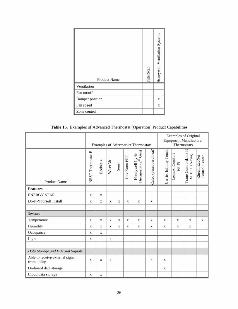
26
Product Name Fil
terS
can
Ho
ney
wel
l V
enti
lati
on
Sy
stem
s
Ventilation
Fan on/off
Damper position
x
Fan speed
x
Zone control
Table 15. Examples of Advanced Thermostat (Operation) Product Capabilities
Examples of Aftermarket Thermostats
Examples of Original
Equipment Manufacturer
Thermostats
Product Name NE
ST
Th
erm
ost
at E
Eco
bee
4
Wis
erA
ir
Sen
si
Lu
x K
ono
PR
O
Ho
ney
wel
l L
yri
c
Th
erm
ost
at (
2nd G
en)
Cal
eo (
bas
ebo
ard
hea
t)
Car
rier
In
fin
ity
To
uch
Len
no
x i
Co
mfo
rt
Wi-
Fi
Tra
ne
Co
mfo
rtL
ink
II
XL
10
50
(N
exia
)
Rh
eem
Eco
Net
Co
ntr
ol
Cen
ter
Features
ENERGY STAR x x
Do-It-Yourself Install x x x x x x x
Sensors
Temperature x x x x x x x x x x x
Humidity x x x x x x x x x x
Occupancy x x
Light x
x
Data Storage and External Signals
Able to receive external signal
from utility x x x x x
On-board data storage
x
Cloud data storage x x

27
Examples of Aftermarket Thermostats
Examples of Original
Equipment Manufacturer
Thermostats
Product Name NE
ST
Th
erm
ost
at E
Eco
bee
4
Wis
erA
ir
Sen
si
Lu
x K
ono
PR
O
Ho
ney
wel
l L
yri
c
Th
erm
ost
at (
2nd G
en)
Cal
eo (
bas
ebo
ard
hea
t)
Car
rier
In
fin
ity
To
uch
Len
no
x i
Co
mfo
rt
Wi-
Fi
Tra
ne
Co
mfo
rtL
ink
II
XL
10
50
(N
exia
)
Rh
eem
Eco
Net
Co
ntr
ol
Cen
ter
Geofencing x x x x x x
Human-in-the-loop
User programming x x x x x x x x x x x
Scheduled alerts
x x
Automated alerts x x x x x
x x
Energy reporting
x x
Integrated voice control x
Communication Between
Components
Wi-Fi x x x x x x x x x x
Bluetooth x
Open API x x
x x x x
Zigbee
x
Controls and Actuators
Heating/cooling on/off x x x x x x x x x x
Humidity level x x x x x x
Ventilation
x
x
Fan on/off x x x x x x x x x
Fan timing x x
x
Multi-zone (control more than one
thermostat) x
x
Dual fuel capable
x
x
2 or more stage equipment x x x x
x x
Variable capacity equipment
x
Heat pump with auxiliary heat x x x x

28
Table 16. Examples of Indoor Air Quality (Operation) Product Capabilities
Product Name Fo
ob
ot
Net
AtM
o
Aw
air
Bre
ezo
met
er
Fil
terS
can
Air
Ad
vic
e
Ho
ney
wel
l V
enti
lati
on
Sy
stem
s
Nig
htB
reez
e
Ap
rila
ire
Deh
um
idif
ier
Features
Do-It-Yourself Install x x x x x x
Sensors
Air Temperature x x x
x x x
Humidity x x x
x x x
Occupancy
CO2 x x x x
x
Air Pressure
x
x
Data Storage and External Signals
Able to receive external signal from utility
On-board data storage
x
Cloud data storage x x x
Local server
x
Human-in-the-loop
User Programming
x x
Automated Programming
Scheduled alerts
Automated alerts
x x x
Communication Between Components
Wi-Fi x x x
x
Bluetooth
API to Connect with Thermostats x x x
ZigBee
Controls
Heating/cooling on/off

29
Product Name Fo
ob
ot
Net
AtM
o
Aw
air
Bre
ezo
met
er
Fil
terS
can
Air
Ad
vic
e
Ho
ney
wel
l V
enti
lati
on
Sy
stem
s
Nig
htB
reez
e
Ap
rila
ire
Deh
um
idif
ier
Humidity level
x
Ventilation
x
Fan on/off
x
Damper position
x x
Fan speed
x x
Zone control
Table 17. Examples of Other Advanced Operation Products and Product Capabilities
Product Name Eco
Ven
t
KE
EN
Ho
me
Ven
t
Ho
ney
wel
l C
om
ple
te (
Inte
gra
ted
HV
AC
Sy
stem
)
Net
AtM
o W
eath
er S
tati
on
Len
no
x i
Har
mo
ny
Sy
mar
o S
enso
rs
Features
Do-It-Yourself Install x x x x
Sensors
Air Temperature x x x x
x
Humidity
x x
x
Occupancy
Air Pressure x x
x
x
Indoor Air Quality
x
Sound
x
Data Storage and External Signals
Able to receive external signal from
utility
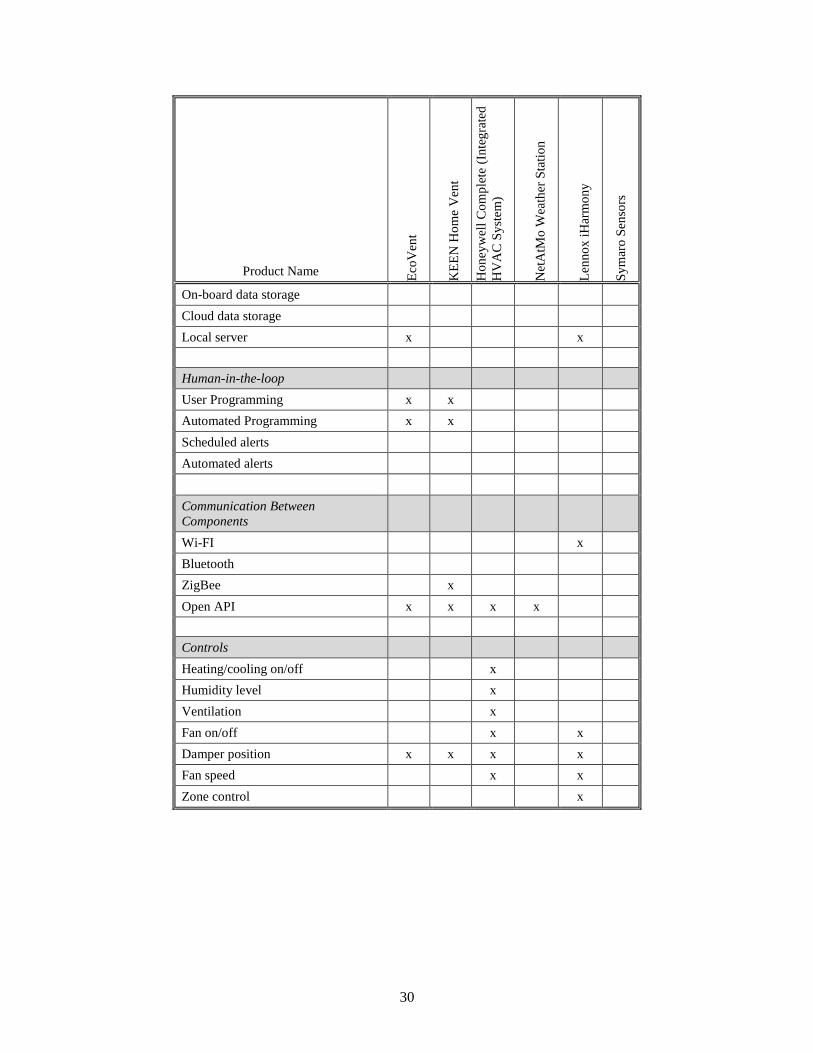
30
Product Name Eco
Ven
t
KE
EN
Ho
me
Ven
t
Ho
ney
wel
l C
om
ple
te (
Inte
gra
ted
HV
AC
Sy
stem
)
Net
AtM
o W
eath
er S
tati
on
Len
no
x i
Har
mo
ny
Sy
mar
o S
enso
rs
On-board data storage
Cloud data storage
Local server x
x
Human-in-the-loop
User Programming x x
Automated Programming x x
Scheduled alerts
Automated alerts
Communication Between
Components
Wi-FI
x
Bluetooth
ZigBee
x
Open API x x x x
Controls
Heating/cooling on/off
x
Humidity level
x
Ventilation
x
Fan on/off
x
x
Damper position x x x
x
Fan speed
x
x
Zone control
x

31
5.0 Remaining Opportunities and Barriers
This section summarizes the remaining opportunities that could help decrease time, cost, energy use, and
human error associated with various advanced HVAC applications. The technical aspects of this section
are organized based on the components described in Section 2: sensors, data storage and external signals,
human-in-the-loop, communication between components, and finally, computation, control, and
actuation. Market barriers round out this section to capture the reoccurring non-technical themes that
appear throughout the paper.
The studies mentioned in this section of the paper use different baseline controllers, buildings, and
systems. Therefore, these studies cannot be compared in a unified manner to conclude anything.
Confounding variables from each study ensure that the findings from individual studies cannot be added
up to find a meaningful comprehensive result. The studies are merely presented to show that advanced
sensing and control can result in significant energy savings and improved comfort.
5.1 Sensors
Occupancy sensors have the potential to save a lot of energy in homes (Piper et al., 2017). From setting
back a thermostat, to lowering the ventilation rate, there are a number of applications that could benefit
from accurate and inexpensive occupancy sensors. There are a few mechanisms by which occupancy is
currently measured in homes. Motion sensors, GPS/geofencing locators, and PIR sensors can be
inexpensive ways to measure occupancy; however, these methods have some limitations. Advanced
occupancy sensors have the potential to measure the number of people and their activity level in homes.
This type of advanced sensor research is currently being done by the Department of Energy’s ARPA-E
Program1 and therefore will not be discussed further.
Other sensors have recently become much more accessible. Motion, temperature, and humidity sensors
are now internet-connected, are relatively inexpensive ($30-$60 each), and can connect to other devices
through open API apps such as IFTTT (e.g., D-Link Motion, ThermoPeanut, MESH, etc.). No known
research has been done with the latest products to determine the level of accuracy or the potential
calibration offset over time. If these sensors have reasonable accuracy over time, they could be used as
conduits for other measurements. For example, with more research a temperature sensor could potentially
be attached to the outside of a refrigerant line to help monitor the refrigerant temperature over time to
determine if there is a sudden change in the temperature of the refrigerant, which often is associated with
certain faults. More research related to the use of low-cost sensors in a home could be helpful to
determine possible applications for commissioning, maintenance, and operation.
5.2 Data Storage and External Signals
Storage and accessibility of equipment meta data could help reduce errors, time on site, and ultimately
make maintenance of HVAC systems less expensive. For example, every time a technician visits a site,
system information (e.g., refrigerant type, stages, equipment type) could be entered for diagnosis and
maintenance purposes. Automatic availability of such information to contractors who connect to the
system (through Wi-Fi for example) could reduce errors, decrease time spent on the site, and expedite the
overall process. Availability of such data (including equipment characteristics) can be quite helpful in
detecting an outlier/fault or optimizing the system performance during operations in automated fashion.
1 https://arpa-e.energy.gov/sites/default/files/documents/files/SENSOR_ProgramOverview_FINAL.pdf

32
Moreover, advanced controls could also achieve a significant amount of energy and cost saving when
responding to a grid dispatch signal for demand response purpose. For example, by responding to a real-
time price signal from the grid, the average electricity energy saving due to peak load shaving is about 5%
(OPOWR 2014; Yoon et al. 2014; Consumers Energy 2014).
5.3 Human-in-the-Loop
Consumer interaction plays a significant role in the efficient operation of an HVAC system. Several field
deployments have shown that consumer feedback devices can lead to 12-15% energy savings (GridTalk
(2013) and Parker et al (2006).
The inability to easily incorporate the end user (actively or passively) in the control loop can have the
reverse effect. A recent study by Callaway et al. (2014) indicates that programmable thermostats of the
time were particularly difficult for users to understand, which led to ineffective usage or even
abandonment. Programmable thermostats capture over 58% of the market, yet 45% of households with
thermostats still set one temperature and leave it most of the time (EIA 2015).
Recent smart thermostat products seem to address this issue by creating an interactive and flexible user
interface. These products seem to be gaining popularity in the market, although as of 2015, the market
share was still only 4% (EIA 2015). At this point, although the number of smart thermostat users is
relatively low, one study shows that those users are in fact energy conscious and are using the thermostats
to their full potential. A study by Apex Analytics (2017), using NEST thermostats, showed that about
80% of the people who use them were interested in saving energy/money1. As these thermostats become
more mainstream, it will be important to continue to conduct research about if users are allowing the
technology to reach its full potential.
Another area for user interface improvement is related to the ease of use of combined components.
Ideally, one interface would exist that would control and optimize all HVAC-related components. This
software/hardware could use a home’s Wi-Fi connection to automatically detect and connect all of the
components to a simple user interface. Potential areas of interest are summarized below:
development of an interface and learning algorithms that maximize sensor input and simplify direct
user interaction to decrease the occupant burden during setup and use.
an inexpensive and user-friendly hardware and software platform that is compatible with all
components.
an interface that consumers can use to set acceptable utility control parameters for demand response
programs.
5.4 Communication Between Components
Easy implementation of advanced control applications on a large scale would require a high level of
compatibility between equipment from different manufacturers, especially when multiple systems, such
as heating, cooling, humidification, dehumidification, and ventilation systems are involved. The use of
open standards for residential controls would allow for more ready integration of controls. Currently,
most OEM solutions utilize proprietary communications with the exception of the wiring standard to
connect thermostats.
1 Users were asked to opt-in to an energy saving program and about 80% of users accepted. Attrition was minimal
and was less than 5% at the conclusion of the study.
33
Smart or connected thermostats play a crucial role in connecting and interacting with HVAC related
equipment and systems. These thermostats provide hardware to gather user inputs, compute control
actions, and send actuation commands to HVAC equipment. Other state-of-the-art computation platforms
are also entering the market. With multiple manufacturers responsible for the HVAC equipment, user
interfaces, sensors, and actuators, there is a growing market for open API communication protocols that
enable interoperability among these technologies.
Most manufacturers do not provide the capability to extract data from the system. However, they will
allow a connection to certain other products in order to improve the flexibility and functionality of their
product. For example, some manufacturers are working with each other directly (e.g., Ecobee and
Amazon Alexa). Even more manufacturers are signing up for a more open integration platform, like
IFTTT, which can use hundreds of devices to sense and control various products in a home. It would be
beneficial to have all sensors, thermostats, actuators, and HVAC equipment with the following
capabilities:
ability to incorporate additional sensors into the system seamlessly, including “plug and play” and
auto-configuration functionality.
availability of component-level information (including sensor data), which may require establishing
two-way communication between devices.
cyber security to prevent unauthorized access of connected equipment.
In general, there are a few product categories that do not currently have any compatibility or
communication capabilities. For example, most refrigerant-side monitoring equipment does not connect
to Wi-Fi, nor does it connect to other devices in the home. Although this equipment is currently used as a
one-time commissioning or retro-commissioning product, with enhanced communication capabilities, it
could be used for maintenance as well. Other product categories with little to no compatibility with other
vendors include (de)humidification equipment and ventilation equipment.
5.4.1 Opportunities for Refrigerant Sensor Communication
A glaring missed opportunity related to communication between components appears in Table 15
(Section 4.0). This table shows how most of the products on the market today that could help detect and
communicate faults from the refrigerant side of heat pump and air-conditioning systems are not
permanently placed, nor are they connected to the internet.
Goetzler et al. (2012), show that central AC and heat pump FDD algorithms could save 0.40 quads of
energy. In particular, improper refrigerant charge is the most important fault to be addressed. Proctor
(2004) reported that about 62% of residential air conditioners had incorrect refrigerant charge, and 35-
45% of residential HVAC systems suffer from insufficient refrigerant charges; this decreases the system
efficiency by 12-20%. Detecting low charge faults in the residential AC units and correcting them would
reduce the cooling energy consumption by 5-10%, which is equivalent to 0.1-0.2 quads of energy savings
(Roth et al. 2006).
FDD provides several other significant benefits that also amortize over the life of an HVAC system.
These benefits, beyond reduced electricity use, include more efficient preventative maintenance services,
increased system lifetime, reduced number of repair parts, and reduced labor (Roth et al. 2006; Wiggins et
al. 2012).

34
Clearly, permanently placed, internet-connected refrigerant sensors with an open API could be used to
help save a substantial amount of energy.
5.4.2 Automated System Zoning
Another example of interconnectivity that could provide a substantial amount of energy savings is
automated system zoning. This would require sensors (e.g., temperature, occupancy, and potentially air
pressure) to be connected to controllers (e.g., air dampers) through a central hub that could perform
computations and interaction with the user. Brown et al. (2007) used an occupancy schedule to dictate the
set points for individual zones during the heating season. The report shows 26% energy reduction with
register controls. A multi-zone setback strategy implemented by Oppenheim et al. (1992) results in 12%
energy savings as compared to a single-zone strategy with an 8-hour 12°F setback. Automating this type
of control could help ensure that occupant comfort was not sacrificed for energy savings.
5.4.3 Opportunities for Ductless Mini-split Communication with Central Systems
For the last 5 years or so, many utilities have provided incentives for residential ductless mini-splits, with
most homeowners adding one indoor unit in a central living area. Controls for these systems have been
disjointed and not suitable for pairing ductless mini-splits with pre-existing systems such as forced-air
furnaces, zonal electric resistance, or boilers with radiant heaters. One study has shown that the
interaction between ductless mini-splits and central systems is not trival (Sutherland et al., 2016).
Additionally, anecdotal post-installation reviews1 of these homes have shown that these units are not
reaching their full potential because the previous existing heating system continues to operate in parallel
with the mini-split. Controllers that communicate between both systems, especially with analytical
capabilities, could help this equipment reach its full potential.
5.5 Computation, Controllers and Actuators
There are many ways that computation, controllers and actuators can be improved. One example is
variable actuation. Although 2-stage equipment and variable speed fans in air handlers are currently
uncommon in residential buildings, these features have the potential to save a lot of energy if used
correctly in conjunction with many of the applications discussed in Section 3.0. For example, the DOE
test procedure and ASHRAE test procedure in 2006 show that 2-stage furnace control can improve energy
efficiency by 3% as compared to single-stage furnaces. One report also showed that even replacement
fans with variable speed capacities could save over 150 kWh/year (Aldrich and Williamson, 2014). Being
able to control these variable actuators could provide substantial savings opportunities for the U.S.
There are other opportunities besides the central HVAC system where the use of this technology could
save energy. For example, the control technologies used in most of the humidity and ventilation
(ERV/HRV) systems offer binary control, e.g., on/off, open/closed. Similarly, most of the existing whole-
home air purification systems are continuously on, offering no control flexibility. Increasing the control
flexibility of these systems could provide more precise control of outputs, reduce oscillations, and
increase overall equipment life. Therefore, it is important to develop or integrate technologies that
increase the actuation flexibility of all motorized technology, not just the primary air handler.
1Including homes from Efficiency Maine and the Bonneville Power Administration
35
Moreover, increasing control flexibility will also provide an opportunity to correct faults automatically in
certain situations, and avoid or delay a technician visit while retaining the system performance.
5.6 Market Barriers
A number of market barriers could be addressed to accelerate the uptake of advanced HVAC controls,
smart sensors, and their associated firmware/software in the residential market. Consumers consider first
cost as the primary obstacle holding them back from purchasing smart HVAC devices that are capable of
implementing advanced controls (Danova 2014). While prices for some control devices have declined,
prices for high end, effective models are still high (Callaway et al. 2014). The next most common market
barrier for consumers is the lack of awareness and education on how devices operate. We have already
discussed how this applies to programmable thermostats. Another barrier for consumers is the issue of
cyber security and privacy. Consumers might view smart HVAC controls as introducing risk to a device
that formerly had none. A report from the California Energy Commission (Ghansah 2012) highlights a
few cyber security and privacy issues that may arise from using current programmable communication
thermostats and advanced metering infrastructure.
Lastly, for smart HVAC controls to reap additional monetary savings for consumers, they should also
have grid interoperability functionality that can take advantage of real-time utility rates or utility
incentives. This calls for the proliferation of utility programs and business models that incentivize load-
shifting behavior.


37
6.0 References
Aldrich, R and J. Williamson. 2014. “Evaluation of Retrofit Variable-Speed Furnace Fan Motors.
DOE-102014-4306. National Renewable Energy Laboratory, Golden, CO.
https://www.nrel.gov/docs/fy14osti/60760.pdf
Apex Analytics. 2017. “Energy Trust of Oregon Nest Thermostat Seasonal Savings Pilot Evaluation.”
November 22, 2017. Prepared by Apex Analytics, LLC and Demand Side Analytics.
Baechler M and H Hao. 2016. “Business Case for Nonintrusive Load Monitoring.” PNNL-25425,
prepared for the Bonneville Power Administration by Pacific Northwest National Laboratory,
Richland, Washington.
Brown CA. 2007. “Multizone register controlled residential heating: Optimized for energy use and
comfort.” MS Thesis, U. C. Berkeley.
Brown SA, BA Thornton, SH Widder and MC Baechler. 2013. “Review of Residential Low-Load
HVAC Systems.” PNNL-23017, Pacific Northwest National Laboratory, Richland, Washington.
https://www.pnnl.gov/main/publications/external/technical_reports/PNNL-23017.pdf
Callaway L and N Strother. 2014. “Executive Summary: Smart Thermostats – Communicating
Thermostats, Smart Thermostats, and Associated Software and Services: Global Market Analysis and
Forecasts.” Navigant Research. Washington, D.C. Accessed on November 12, 2015 at
https://www.navigantresearch.com/research/smart-thermostats
Danova T. 2014. The Connected Home Report: Forecasts and Growth Trends FOR THE Leading
‘Internet of Things’ Market. Business Insider Intelligence. Accessed on November 12, 2015 at
http://www.businessinsider.com/connected-home-forecasts-and-growth-2014-9
DOE (U.S. Department of Energy). 2016a. “Maintaining Your Air Conditioner.” Accessed on
December 30, 2016. https://www.energy.gov/energysaver/maintaining-your-air-conditioner
DOE (U.S. Department of Energy). 2016b. “Overview of Existing and Future Residential Use Cases
for Connected Thermostats.” Accessed on December 29, 2016 at
https://energy.gov/eere/buildings/downloads/overview-existing-and-future-residential-use-cases-
connected-thermostats
DOE (U.S. Department of Energy). 2016d. “The National Opportunity for Interoperability and its
Benefits for a Reliable, Robust, and Future Grid Realized Through Buildings.” DOE/EE-1341
Domanski PA, HI Henderson, and WV Payne. 2014. “Sensitivity Analysis of Installation Faults on
Heat Pump Performance,” NIST Technical Note 1848:9-16.
EERE (Office of Energy Efficiency and Renewable Energy). 2011. Final Rule Technical Support
Document: Energy Conservation Standards for Residential Central Air Conditioners, Heat Pumps,
and Furnaces. EERE-2011-BT-STD-0011, U.S. Department of Energy, Washington, DC. Accessed
on November 12, 2015 at
http://www.regulations.gov/#!documentDetail;D=EERE-2011-BT-STD-0011-0012
EIA (Energy Information Administration). 2015. “Residential Energy Consumption Survey (RECS).”
U.S. Department of Energy, Washington, D.C.

38
EIA (Energy Information Administration). 2015 “Monthly Energy Review Oct 2015.” U.S.
Department of Energy, Washington, D.C. Accessed on November 12, 2015 at
http://www.eia.gov/totalenergy/data/monthly/pdf/sec2.pdf
EIA (Energy Information Administration. 2013. How much electricity does an American home use.
Accessed November 12, 2015 at http://www.eia.gov/tools/faqs/faq.cfm?id=97&t=3
EIA (Energy Information Administration). 2009. “Residential Energy Consumption Survey (RECS).”
U.S. Department of Energy, Washington, D.C.
EPA (U.S. Environmental Protection Agency). 2016. “ENERGY STAR HVAC Quality Installation
Program.” Accessed on December 30, 2016.
https://www.energystar.gov/ia/home_improvement/downloads/ESQI_factsheet.pdf?8fd5-1967
Gao G and K Whitehouse. 2009. “The Self-Programming Thermostat: Optimizing Setback Schedules
based on Home Occupancy Patterns.” In First ACM Workshop on Embedded Sensing Systems for
Energy-Efficiency in Buildings, New York, NY.
Ghansah I. 2012. Smart grid cyber security potential threats, vulnerabilities, and risks. California
Energy Commission. Accessed on December 22, 2015 at
http://www.energy.ca.gov/2012publications/CEC-500-2012-047/CEC-500-2012-047.pdf
Goetzler W, R Zogg, J Young, and J Schmidt. 2012. “Energy Savings Potential and RD&D
Opportunities for Residential Building HVAC Systems.” U.S Department of Energy.
http://www1.eere.energy.gov/buildings/pdfs/residential_hvac_research_opportunities.pdf
Goyal, S., H. Ingley, and P. Barooah. 2013. “Energy-efficient control of an air handling unit for a
single-zone VAV system.” In Proceedings of IEEE 52nd Annual Conference on Decision and Control
(CDC), pp. 4796–801. Florence, Italy.
Goyal, S., and P. Barooah. 2015. "Experimental study of occupancy-based control of HVAC zones",
Applied Energy, vol. 140, p75-84.
GridTalk. 2013. Shaving Peak Residential Electricity Demand with Grid-Based Technology. Accessed
on Nov 12, 2015 at http://www.sandc.com/blogs/index.php/2013/03/shaving-peak-residential-
electricity-demand-with-grid-based-technology/
Lstiburek JW and B Pettit. 2010. “Final Report on the Expert Meeting for Diagnostic and Performance
Feedback for Residential Space Conditioning System Equipment.” DE-FC26-08NT00601, Building
Science Corporation, Westford, Massachusetts.
Maasoumy, M. 2016. “Smart Connected Buildings Design Automation Foundations and Trends.”
Foundations and Trends®
in Electric Design Automation, Vol 10, No 1-2, pp1-143.
http://dx.doi.org/10.1561/1000000043
Oppenheim, P. 1992. “Energy-Saving Potential of a Zoned Forced-Air Heating System.” ASHRAE
Transactions.
Parker, D., D. Hoak, et al. 2006. “How Much Energy Are We Using? Potential of Residential Energy
Demand Feedback Devices.” 2006 ACEEE Summer Study on Energy Efficiency in Buildings,
Asilomar, CA.

39
Piper, B., I. Metzger, N. Ricciardi, and Z. Gao, 2017. “Home Energy Management Pilot System
Savings Validation Pilot.” New York State Energy Research and Development Authority. Report
Number 17-16. Albany, NY.
Proctor J. 2004. “Residential and Small Commercial Air Conditioning – Rated Efficiency Isn’t
Automatic.” In Proceedings of the ASHRAE Winter Meeting, Anaheim, California.
Roth K, D Westphalen, and J Brodrick. 2006. “Residential central AC fault detection and
diagnostics.” ASHRAE Journal 48.5, pp. 96–97.
Siemann M. 2010. “Performance of Residential Heating and Cooling Control Strategies using
Distributed Wireless Sensor Networks.” MS Thesis. University of Maryland, College Park.
Singer BC, WW Delp, DR Black, and IS Walker. July 2017. “Measured performance of filtration and
ventilation systems for fine and ultrafine particles and ozone in an occupied modern California house.”
Indoor Air 27.4, pp.780-790.
Somasundaram S, S Katipamula, RG Pratt, ET Mayhorn, BA Akyol, A Somani, N Fernandez, A
Steckley, N Foster, and ZT Taylor. 2014. “Transaction-Based Building Controls Framework, Volume
1: Reference Guide.” PNNL-23302, Pacific Northwest National Laboratory, Richland, Washington.
http://bgintegration.pnnl.gov/pdf/PNNL_23302.pdf
Sutherland, K, Parker D, Martin, E. 2016. “Evaluation of Mini-Split Heat Pumps as Supplemental and
Full System Retrofits in a Hot Humid Climate. FSEC-RR-646-16. Presented at 2016 ACEEE Summer
Study on Energy Efficiency in Buildings. http://www.fsec.ucf.edu/en/publications/pdf/fsec-rr-646-
16.pdf
Wang N, and JD Goins. 2015. Buildings of the Future Scoping Study: A Framework for Vision
Development. PNNL-24126, Pacific Northwest National Laboratory, Richland, WA.
Walker IS. 2014. “Smart Ventilation (RIVEC) – 2014 BTO Peer Review. Slide 3.
https://energy.gov/sites/prod/files/2014/05/f16/rbi09_Singer_042414.pdf
Wiggins, M., and J. Brodrick. 2012. “HVAC fault detection,” ASHRAE Journal, 54(2):78-80.
