review article recent developments in multiscale and...
TRANSCRIPT

Review ArticleRecent Developments in Multiscale and Multiphase Modelling ofthe Hydraulic Fracturing Process
Yong Sheng,1 Marina Sousani,1,2 Derek Ingham,2 and Mohamed Pourkashanian2
1School of Civil Engineering, University of Leeds, Leeds LS2 9JT, UK2Energy Technology and Innovation Initiative (ETII), University of Leeds, Leeds LS2 9JT, UK
Correspondence should be addressed to Yong Sheng; [email protected]
Received 9 December 2014; Revised 6 July 2015; Accepted 12 July 2015
Academic Editor: Xiaoying Zhuang
Copyright © 2015 Yong Sheng et al. This is an open access article distributed under the Creative Commons Attribution License,which permits unrestricted use, distribution, and reproduction in any medium, provided the original work is properly cited.
Recently hydraulic fracturing of rocks has received much attention not only for its economic importance but also for its potentialenvironmental impact. The hydraulically fracturing technique has been widely used in the oil (EOR) and gas (EGR) industries,especially in theUSA, to extractmore oil/gas through the deep rock formations. Also there have been increasing interests in utilisingthe hydraulic fracturing technique in geological storage of CO
2in recent years. In all cases, the design and implementation of
the hydraulic fracturing process play a central role, highlighting the significance of research and development of this technique.However, the uncertainty behind the frackingmechanismhas triggered public debates regarding the possible effect of this techniqueon human health and the environment. This has presented new challenges in the study of the hydraulic fracturing process. Thispaper describes the hydraulic fracturing mechanism and provides an overview of past and recent developments of the researchperformed towards better understandings of the hydraulic fracturing and its potential impacts, with particular emphasis on thedevelopment of modelling techniques and their implementation on the hydraulic fracturing.
1. Introduction
Hydraulic fracturing, or fracking, is a technique used inthe mining industry and involves the controlled crackingof the rock formation with the use of high pressure liquidfluids [1]. The technique of hydraulically fracturing the rockshas been well known since it has been widely used forEnhanced Oil Recovery (EOR) and Enhanced Gas Recovery(EGR) in the oil and gas industries, especially in the USA,to extract more oil/gas through the deep rock formations[2, 3]. Hydraulic fracturing is a combination of processes,such as the deformation of the formation due to an externalmechanical load (i.e., fluid pressure), the fluid flow throughpreexisting cracks of the formation, and the propagation ofcracks [4, 5]. While the technology behind these processeshas been used for more than 30 years in the name of energyexploitation, underground formations constitute a complexsystem of variables (both rock and well properties) that arenot fully understood and thus are still under investigation[6, 7].
Scientists over the years have concluded that there is aclear relationship between the increase of CO
2and human
activities [8–10]. Overpopulation and therefore extensiveindustrial activities contribute greatly to the increase ofgreenhouse gas emissions and countries have agreed toa common mitigation plan in order to reduce the CO
2
emissions to acceptable levels and achieve a low carbonenergy future [9, 11–14]. CarbonCapture and Storage (CCS) isa promisingmethod that plays a central role as part of themit-igation plan [10, 15–18]. CCS is a five-step procedure whichembraces all stages of industrial production [19]. Specifically,it involves the capture of high amounts of CO
2produced
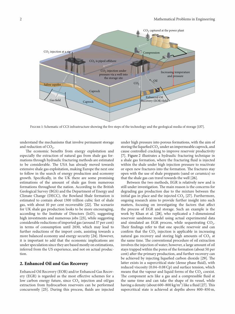
from industrial facilities before they are released into theatmosphere, its liquefaction and pipeline transport into thesite (oil and gas reservoirs, saline formations), injection underhigh pressure, and storage in deep underground formations[20]. Figure 1 illustrates all stages of the CCS technology fromcapture until storage. The hydraulic fracturing techniqueon porous media has become part of the injection andstorage stage of CCS [1, 21] and therefore it is essential to
Hindawi Publishing CorporationMathematical Problems in EngineeringVolume 2015, Article ID 729672, 15 pageshttp://dx.doi.org/10.1155/2015/729672
2 Mathematical Problems in Engineering
CO2 injection at a rig
Saline aquifer
Gas field
Caprock
Caprock
CO2 is piped offshore
CO2 injection underpressure via a well into
the storage siteCO2
CO2 captured at the power plant
Compression
Oil
Enhanced Oil
Increasing temperatureand pressure
Recovery (EOR) field
Figure 1: Schematic of CCS infrastructure showing the five steps of the technology and the geological media of storage [137].
understand the mechanisms that involve permanent storageand reduction of CO
2.
The economic benefits from energy exploitation andespecially the extraction of natural gas from shale gas for-mations through hydraulic fracturing methods are estimatedto be considerable. The USA has already moved towardsextensive shale gas exploitation, making Europe the next oneto follow in the search of energy production and economygrowth. Specifically, in the UK there are some promisingestimations of the amount of shale gas from numerousformations throughout the nation. According to the BritishGeological Survey (BGS) and the Department of Energy andClimate Change (DECC), the Bowland Shale formation isestimated to contain about 1300 trillion cubic feet of shalegas, with about 10 per cent recoverable [22]. The scenariofor UK shale gas production looks to be more encouraging,according to the Institute of Directors (IoD), suggestinghigh investments and numerous jobs [23], while suggestingconsiderable reductions of imported gas (around 37 per cent)in terms of consumption until 2030, which may lead tofurther reductions of the import costs, assisting towards amore balanced economy and energy security [24]. However,it is important to add that the economic implications areunder speculation since they are basedmostly on estimations,inferred from the US experience, and not on actual produc-tion.
2. Enhanced Oil and Gas Recovery
Enhanced Oil Recovery (EOR) and/or Enhanced Gas Recov-ery (EGR) is regarded as the most effective schemes for alow carbon energy future, since CO
2injection and oil/gas
extraction from hydrocarbon reservoirs can be performedconcurrently [25]. During this process, fluids are injected
under high pressure into porous formations, with the aim ofstoring the liquefiedCO
2under an impermeable caprock, and
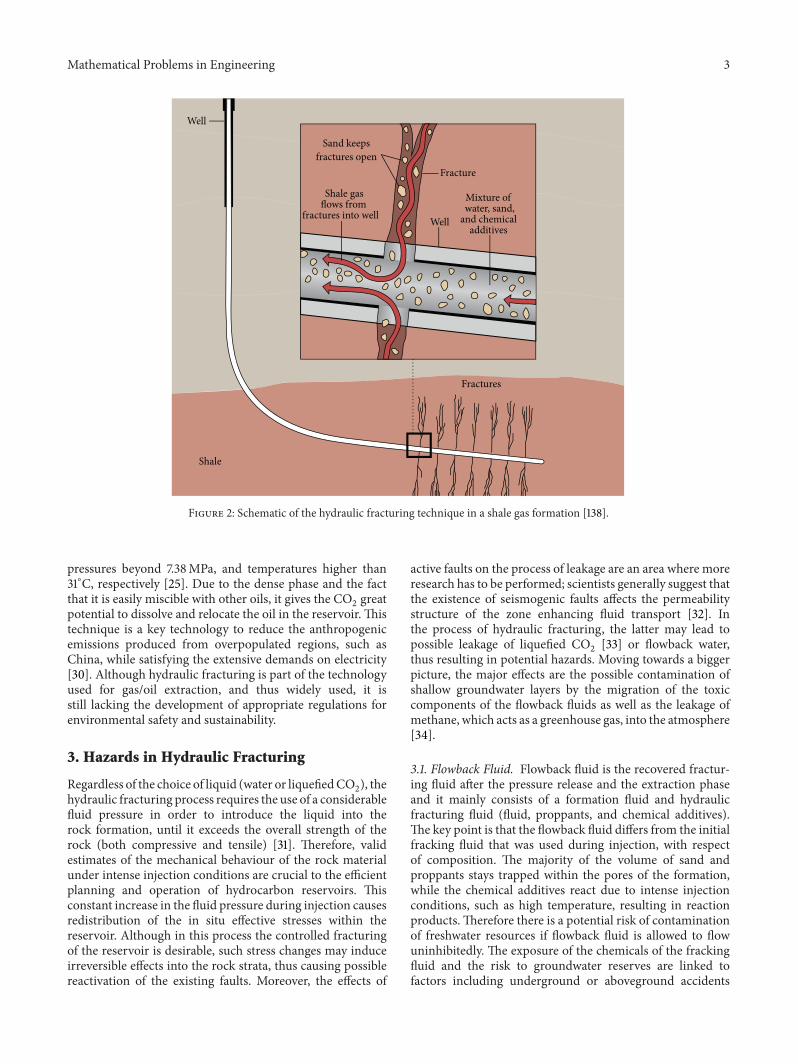
cause controlled cracking to improve reservoir productivity[7]. Figure 2 illustrates a hydraulic fracturing technique ina shale gas formation, where the fracturing fluid is injectedwithin the shale under high injection pressure to reactivateor open new fractures into the formation. The fractures stayopen with the use of shale proppants (sand or ceramics) sothat the shale gas can travel towards the well [26].
Between the two methods, EGR is relatively new and isstill under investigation. The main reason is the concerns fordegrading gas production due to the mixture between theinitial gas in place and the injected CO
2[27]. Furthermore,
ongoing research aims to provide further insight into suchmatters, focusing on investigating the factors that affectthe process of EGR and storage. Such an example is thework by Khan et al. [28], who replicated a 3-dimensionalreservoir sandstone model using actual experimental dataand simulated an EGR process, while sequestrating CO
2.
Their findings refer to that one specific reservoir and canconfirm that the CO
2injection is applicable in increasing
natural gas recovery and storing high amounts of CO2at
the same time. The conventional procedure of oil extractioninvolves the injection of water; however, a large amount of oilstays trapped within the pores of the formation (about 50 percent) after the primary production, and further recovery canbe achieved by injecting liquefied carbon dioxide [29]. Thelatter exists in a supercritical state (dense phase fluid), withreduced viscosity (0.04–0.08Cp) and surface tension, whichmeans that the vapour and liquid forms of the CO
2coexist.
The component acts like a gas and a compressible fluid atthe same time and can take the shape of its vessel, whilehaving a density (about 600–800 kg/m3) like a fluid [27].Thissupercritical state is achieved at depths above 800–850m,
Mathematical Problems in Engineering 3
Well
Well
Sand keepsfractures open
Shale gasflows from
fractures into well
Fracture
Fractures
Mixture ofwater, sand,
and chemicaladditives
Shale
Figure 2: Schematic of the hydraulic fracturing technique in a shale gas formation [138].
pressures beyond 7.38MPa, and temperatures higher than31∘C, respectively [25]. Due to the dense phase and the factthat it is easily miscible with other oils, it gives the CO
2great
potential to dissolve and relocate the oil in the reservoir. Thistechnique is a key technology to reduce the anthropogenicemissions produced from overpopulated regions, such asChina, while satisfying the extensive demands on electricity[30]. Although hydraulic fracturing is part of the technologyused for gas/oil extraction, and thus widely used, it isstill lacking the development of appropriate regulations forenvironmental safety and sustainability.
3. Hazards in Hydraulic Fracturing
Regardless of the choice of liquid (water or liquefiedCO2), the
hydraulic fracturing process requires the use of a considerablefluid pressure in order to introduce the liquid into therock formation, until it exceeds the overall strength of therock (both compressive and tensile) [31]. Therefore, validestimates of the mechanical behaviour of the rock materialunder intense injection conditions are crucial to the efficientplanning and operation of hydrocarbon reservoirs. Thisconstant increase in the fluid pressure during injection causesredistribution of the in situ effective stresses within thereservoir. Although in this process the controlled fracturingof the reservoir is desirable, such stress changes may induceirreversible effects into the rock strata, thus causing possiblereactivation of the existing faults. Moreover, the effects of
active faults on the process of leakage are an area where moreresearch has to be performed; scientists generally suggest thatthe existence of seismogenic faults affects the permeabilitystructure of the zone enhancing fluid transport [32]. Inthe process of hydraulic fracturing, the latter may lead topossible leakage of liquefied CO
2[33] or flowback water,
thus resulting in potential hazards. Moving towards a biggerpicture, the major effects are the possible contamination ofshallow groundwater layers by the migration of the toxiccomponents of the flowback fluids as well as the leakage ofmethane, which acts as a greenhouse gas, into the atmosphere[34].
3.1. Flowback Fluid. Flowback fluid is the recovered fractur-ing fluid after the pressure release and the extraction phaseand it mainly consists of a formation fluid and hydraulicfracturing fluid (fluid, proppants, and chemical additives).The key point is that the flowback fluid differs from the initialfracking fluid that was used during injection, with respectof composition. The majority of the volume of sand andproppants stays trapped within the pores of the formation,while the chemical additives react due to intense injectionconditions, such as high temperature, resulting in reactionproducts.Therefore there is a potential risk of contaminationof freshwater resources if flowback fluid is allowed to flowuninhibitedly. The exposure of the chemicals of the frackingfluid and the risk to groundwater reserves are linked tofactors including underground or aboveground accidents
4 Mathematical Problems in Engineering
during transport and the concentration/handling of thepossible hazardous substances [35]. Currently, the issue ofpotential implications on the quality of water is a matter ofdebate. This is due to lack of available information on thecomposition of the chemicals used in hydraulic fracturingprocedures, and therefore scientists focus on this part ofresearch aiming to shedmore light. Recent studies are dealingwith the ecotoxicological assessment of undiluted fracturingfluids, which indicate a hazardous effect on aquatic life.These studies are based on component-based prognosticmodels rather than measuring the ecotoxicological effect of afracturing fluid as a whole [36].This provides better accuracyof the overall results, allowing the prognosis of the effectof the mixture components individually. Generally, flowbackfluids contain a mixture of hydraulic fracturing fluid andformation water. The potency of flowback fluid depends onthe mix ratio of the formation water and fracturing fluidand although a high proportion of the fracturing fluid maybe retained in the formation there is a high tendency forflowback to take place as a result of imposed fracturingoperations [37]. At present, very limited studies have dealtwith the chemical composition of flowback or its potentialpollutants, and there are no studies investigating the differ-ence in fracturing fluid from formationwater that contains nofracturing fluid in flowback. The work performed by Olssonet al. [37] aims to bridge the knowledge gap by analysingthe composition and volumes of flowback from differentsites in Germany. This research has revealed that no singletechnology can meet the criteria for the overall treatment offlowback; thus they categorized the flowback fluid into groupsand suggested some treatment methods. Furthermore, theaccidental penetration of the fracturing and flowback fluidsinto the water aquifers and their impact on the human-healthbecomes critical and has been addressed recently. Such anexample is the work by Gordalla et al. [35] who focused onthe assessment of the ingredients of the fracturing fluids onthe human-toxicological point of view, the influence of theflowback, and the possible hazards of freshwater reservesand suggested methods for minimising the environmentalimpact. Moreover, apart from the importance of extendingthe available information on the chemical composition offracturing fluids or the environmental impact of the flowbackand its proposed treatingmethods, it is of equal importance toinvestigate the underground formations and their interactionwith the potential migrating fracturing fluids or methane.Such an example is the work by Lange et al. [38] who aimed toidentify fault zones as preferential pathways that facilitate themovement of fracturing fluids/methane in unconventionalgas reservoirs and analysed the effectiveness of the differentlayers of overburden.
3.2. Risk of Contaminated Aquifers. The extensive use ofunconventional fracking (horizontal drilling and high vol-ume hydraulic fracturing), especially in the USA, has trig-gered a public debate regarding possible health issues relatedto drinking water. Although industry claims that shale gasfracking is safe with minimum environmental impacts, theEuropean Commission states that the extraction of uncon-ventional hydrocarbons (shale gas) generally imposes a larger
environmental footprint than conventional gas extraction[39]. Risks from ongoing operations may include surfaceand groundwater contamination, water resource depletion,air and noise emissions, land take, disturbance to bio-diversity, and impacts related to traffic. People’s concern,especially in European countries where groundwater is theirmain resource of drinking water, has forced countries toseek expert opinion. A typical example is Germany andthe ExxonMobil initiative [40]. The latter has formed amultidisciplinary working group in order to identify thepossible environmental risks for the Lower Saxony Basin.Their main task is to assess the available technology (drillingand technical processes) and develop a strategy that fits therequirements for safe hydraulic fracturing operations. Part ofthis assessment is the “information and dialogue process onhydraulic fracturing,” focusing on the characterization of thehydrogeological system, the chemical reactions under whichleakage may occur, the possible leakage pathways, and thedevelopment of suitable models and their results [34, 38].
4. Modelling of Rock Fragmentation andFluid Flow Problems
Moreover, the rapid growth in computer power and mod-elling has resulted in the development of a large numberof software packages used for the numerical analysis ofcomplex engineering problems, such as the identificationof problematic (low bond strength) material parameters inmasonry structures [41]. The reason for this is that it isvery difficult for the analytical modelling to measure anddescribe accurately the complicated problems associatedwithfracturing. In subsurface investigations in particular, whereheterogeneity and awide range of complex innermechanismscoexist, numerical modelling is necessary to represent reallife scenarios. Numerous mathematical solutions have beenapplied to look, for example, into the critical mechanicalparameters, such as the stress envelope, the porosity andpermeability of the material and the effect of layering withinthe rock, or the way that these are influenced by theexternal mechanical load [42]. However, studies that employmodelling and simulation of rocks at the microscale [43–45] are fewer and their focus on the complex interplaybetween the microproperties and their corresponding effecton the material’s behaviour during the calibration procedureprovides at best a general guidance.Therefore, a review on themicro-meso-level modelling using Discrete Element Methodis first provided in this section to highlight the researchprogress in recent years in this area, followed by the broaderoverview of multiscale and multiphase coupling models.
4.1. Discrete ElementMethodology. TheDEM is an alternativeapproach, to the Finite Element Method (FEM), which aimsto describe the macroscopic mechanical behaviour of mate-rials as a result of the interaction of its constitutive individualelements. Specifically, in DEM the material is described asa discontinuum, consisting of numerous distinct particleswhich represents the inhomogeneities within the material(joints and/or fractures) in the particle scale [45, 46]. Initiallyparticle scale models were developed in order to simulate the
Mathematical Problems in Engineering 5
behaviour of soils and sands (noncohesive materials) [47].The transition from the aforementionedmodelling to the onethat simulates the micromechanical behaviour of solid rocksis commonly known as the bonded particle model (BPM)for rock [45]. In a BPM, the breakage of interparticle bondssimulates the nucleation of a microcrack, while microcrack-ing is achieved by coalescence of multiple bond breakages.The DEM methodology and the particle-based models havebeen employed in several computer packages in the field ofrock mechanics, such as the particle flow code (PFC), theYADE, the universal distinct element code (UDEC), and thediscontinuous deformation analysis (DDA).
The advantages of the DEM methods over other tra-ditional techniques, such as the Finite Element Method(FEM), are the simpler representation of the geometries ofreal rocks, which contain discontinuities, the easier sim-ulation of complex engineering problems without the useof complicated constitutive equations, and thus providestatistically more accurate results. Conversely, the increasedsimplification requires extensive experimental validation toverify the numerical results of the method and proves thatthe microscopic models can produce equivalent macroscopicbehaviour of real rocks. Finally, the increased computationaltime due to the nature of the DEM approach (solving thegoverning equations for a large volume of particles) is anotherlimitation that researchers have to tackle.
4.1.1. Particle Flow Code (PFC). Each of these approaches isbased on the DEMs governing formulations, which includethe calculation of the relativemotion of the discrete elements,such as slip, rotation, or even complete detachment. Morespecifically in PFC each particle’s motion is calculated by theequation of motion, given by
𝐹𝑖+ 𝐹𝑑
𝑖=
{
{
{
𝑚��𝑖, for 𝑖 = 1, 2, 3,𝐼𝜔(𝑖−3), for 𝑖 = 4, 5, 6,
(1)
where 𝐹𝑖is the generalized force which includes the gravita-
tional force, 𝐹𝑑𝑖is the damping force,𝑚 is the particle’s mass,
��𝑖is the particle’s translational acceleration, 𝐼 is the moment
of inertia, and �� is the angular acceleration.For the cases where the virtual particles are connected
with bonds (reproducing the cementation between grains inreal rocks), the updated body forces andmoments, due to thepresence of bonds, are calculated via the force displacementlaw:
𝐹𝑇
𝑖= 𝐹𝑛
𝑖+ 𝐹𝑠
𝑖,
𝑀𝑇
𝑖= 𝑀𝑛
𝑖+𝑀𝑠
𝑖,
(2)
where 𝐹𝑇𝑖, 𝑀𝑇𝑖are the total force and moment vectors and
𝐹𝑛
𝑖, 𝐹𝑠𝑖, 𝑀𝑛𝑖, and 𝑀𝑠
𝑖are the axial and shear components
with respect to the contact plane, respectively. Details onthe PFC calculation cycle based on the DEM can be foundin Sousani et al. [48]. However each approach has itsown limitations. The PFC utilises the BPM model, sincethe parallel bond rock modelling has been widely used
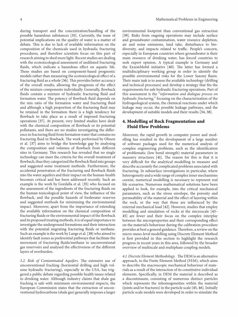
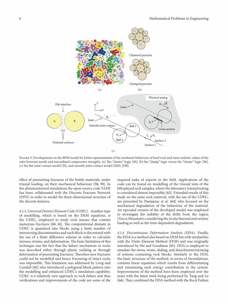
to simulate the fracturing mechanism in brittle rocks, butprevious versions had the disadvantage of unrealistic ratiosbetween the obtained tensile and unconfined compressivestrength, to low nonlinear failure envelopes in terms oftriaxial tests, or the problematic modelling of the interfacesdue to the inherent roughness of the interface surfaces [49].To tackle these limitations of PFC, a number of enhancementmeasures have been developed with the aim of providinga more accurate nonlinear mechanical behaviour, strengthratios, and friction coefficients. The basic concepts includethe “cluster logic” (bonded particles packed together to formangular shapes or blocks that resemble natural grain struc-tures, Figure 3(a)), performed by Potyondy and Cundall [45],the “clump logic” (bonded particles that behave collectivelyas a single unbreakable rigid body, Figure 3(b)) from Cho etal. [50], the flat-joint contact model (a more efficient contactformulation, where disk-shaped particle contacts simulate afinite-length interface that has relative rotation, even uponbond breakage, Figure 3(c)) from Potyondy [51], and finallythe smooth-joint contact model (SJM) and the synthetic rockmass approach (SRM), respectively, fromMas Ivars [52, 53].
The SJM model simulates the behaviour of an interfacedisregarding the particle contact orientations locally along-side the interface, while the SRM model is a combinationbetween the BPM and the SJM models that describes themechanical behaviour of jointed rock masses, includinganisotropy, brittleness, and scaling effects which cannot beachieved by empirical methods.
4.1.2. Open-Source Software YADE. Recently, another par-ticle-based code has been developed, called YADE, as analternative approach to the well-known commercial PFCcode as previously described [54, 55]. YADE aims to bemore flexible by adding new modelling capabilities, severalsimulation methods (e.g., DEM, FEM, and Lattice Geo-metrical Model (LGM)) can be coupled within the sameframework and also the scientific community can providedirect feedback for improvement of the code with the useof an open-source platform. The fundamental principles ofYADE are similar to those of PFCwith respect to small defor-mations and fracturing (linear elastic interparticle forcesand bond breakage, resp.) but new features, simulating rockdiscontinuities and ensuring frictional behaviour regardlessof the inherent roughness, have been implemented as analternative approach to the SJM and SRM models [56]. Inaddition, the use of YADE in studying the failure of brittlerocks has led to the creation of additional features, such asthe interaction range coefficient, which helps to accuratelysimulate high ratios of compressive to tensile strengths as wellas nonlinear failure envelopes [57]. However, YADE as wellas many of the open-source software packages appear to beinefficient when compared to commercial software such asPFC, mainly due to the complexity of the user’s interface andthe lack of user defined functions. Moreover, open-sourcesoftware solutions tend to developmainly in line with specificpurposes and also rely on the pool of open resources tohelp to discover errors and bugs. Some applications of theYADE code include three-dimensional simulations of theprogressive damage in fractured rock masses [56], or the
6 Mathematical Problems in Engineering
(a)
Clustered particles
Clumped particles
+
(b)
2R
A B
Flat interface
Notional surfaces
Physical analog
Joint
Smooth-joint contact Ball 1
Ball 2Surface 1
Surface 2
Cross section
ne
njtjne
y
x
𝜃F
Joint
(c)
Figure 3: Developments on the BPMmodel for better representation of the nonlinear behaviour of hard rock andmore realistic values of theratio between tensile and unconfined compressive strengths. (a) The “cluster” logic [45], (b) the “clump” logic versus the “cluster” logic [50],(c) the flat-joint contact model [51], and smooth-joint contact model (SJM) [139].
effect of preexisting fractures of the brittle materials, undertriaxial loading, on their mechanical behaviour [58, 59]. Inthe aforementioned simulations the open-source code YADEhas been collaborated with the Discrete Fracture Network(DFN) in order to model the three-dimensional structure ofthe discrete features.
4.1.3. Universal Distinct Element Code (UDEC). Another typeof modelling, which is based on the DEM equations, isthe UDEC, employed to study rock masses that containnumerous fractures [60, 61]. The computational domain inUDEC is quantized into blocks using a finite number ofintersecting discontinuities and each block is discretized withthe use of a finite difference scheme in order to calculatestresses, strains, and deformation.The basic limitation of thistechnique was the fact that the failure mechanism in rockswas described either through plastic yielding or throughdeformation of preexisting fractures.Therefore new fracturescould not be modelled and hence fracturing of intact rockswas impossible. This limitation was addressed by Lorig andCundall [62] who introduced a polygonal block pattern intothe modelling and enhanced UDEC’s simulation capability.UDEC is a relatively new approach to rock failure and thusverifications and improvements of the code are some of the
required tasks of experts in the field. Applications of thecode can be found on modelling of the triaxial tests of thelithophysal rock samples, where the laboratory triaxial testingis considered almost impossible [63]. Extended results of thisstudy on the same rock material, with the use of the UDEC,are presented by Damjanac et al. [64] who focused on themechanical degradation of the behaviour of the material.An upscaled version of the developed model was employedto investigate the stability of the drifts from the region(YuccaMountain) considering the in situ thermal and seismicloading as well as the time-dependent degradation.
4.1.4. Discontinuous Deformation Analysis (DDA). Finally,theDDA is amethod also based onDEMbut with similaritieswith the Finite Element Method (FEM) and was originallyintroduced by Shi and Goodman [65]. DDA is employed tosimulate the stress, strain, sliding, and detachment/rejoiningof systems containing rock blocks. Similarly to the FEM,the basic structure of the method, in terms of formulations,contains linear equations which results from differentiatingand minimizing each energy contribution to the system.Improvements of the method have been employed over theyears with the latest work being performed by Tang and Lu[66].They combined the DDAmethod with the Rock Failure
Mathematical Problems in Engineering 7
Process Analysis (RFPA) software, the latter based on contin-uum mechanics [67], to investigate large scale deformationsof discontinuous rock systems using the capability of RFPA tocapture small deformation, crack initiation/propagation, andcoalescence in intact rocks.
4.2. Combined FEM/DEM and Other Hybrid Techniques.The FEM and its improved approaches are considered astandard technique that can be successfully applied to numer-ous problems, such as the modelling and evaluation ofrock materials or rock failure with internal discontinuities[68–70]. An example of a FEM is the two-dimensionalfinite difference programme FLAC [71]. This programme isemployed to investigate the behaviour of materials such assoil and rocks and more specifically it simulates soil androck structures that may undergo plastic deformation oncetheir maximum yield limits have been reached. FLAC userscreate a grid, which consists of elements and zones, whichfits the shape of the sample to be modelled. However, dueto its geometric limitations, more discretization methodshave been developed to address its difficulties, such as theextended Finite ElementMethod (XFEM) [72] for computingthe three-dimensional crack propagation [73, 74], specifi-cally focusing on the improvement of meshing sensitivityemployed to compute the fragmentation problems [75]. Anumber of hybrid techniques have been developed based onthe FEM with DEM implementations. This combination iscalled the hybrid continuum-discontinuum method or thecombined FDEM and includes models such as the ELFEN(Finite Element/Discrete Element System) [76] or the Y-Geosoftware [77, 78] which are based on the Finite ElementMethod to describe the solid part of interest but also adoptthe theory of the Discrete Element Method. The conceptin FDEM is the transfer from continuum to discontinuumthrough fragmentation. Specifically, the sample’s matrix ismodelled with the use of continuum mechanics and asthe test progresses the equations of motion are integrated.Then the initiation of cracks/fragmentations is such that itsatisfies suitable fracture criteria, which therefore leads tothe formation of new individual discrete bodies. Comparingthe FDEM with the FEM and the DEM, respectively, wecan claim that it is more capable of capturing the behaviourof postrock fragmentation and also it is more flexible inmodelling deformable and unique-shaped particles. Further-more, between the two modelling techniques, the Y-Geoapproach resembles more a discrete method. Specifically, therepresentation of a sample with the use of Y-Geo is closer toa particle-based model, where the particles and their bondsare replaced by deformable triangle elements and four-nodedcohesive elements [77], whereas in ELFEN a transfer betweena continuous elastoplastic sample and a sample with discretefractures is achieved by importing cracks into the sample [79].
4.3. Modelling of Fluid Flow in Hydraulic Fracturing. Awide range of engineering problems could utilise the DEMapproach coupled with fluid models to analyse the frackingprocess within the rock specimen [21] or the influence of thesignificant parameters, such as the injection pressure, to asuccessful injection/storage application [80]. Also it is used
to simulate the behaviour of materials such as sandstone andlimestone and the fluid-solid interactions among them [45,81]. Initially, the fluid-solid interactions were described bythe lattice Boltzmannmethod, which computes the fluid flowand solves the discretised form of the Boltzmann equation,based on the Navier-Stokes equation [82]. Other methods forcomputing the fluid flow include Direct Numerical Simula-tion (DNS) [83, 84], where the flow variables (e.g., pressureand velocity) exist as a function of space and time and can beobtained from the numerical solutions of the Navier-Stokesformulations, and Computational Fluid Dynamics (CFD).However, the need to provide linkages between the coexistingfluid and the solid phases necessitates a coupling of thesetechniques with the modelling of the solid phase, such asthe DEM.The lattice Boltzmann and the DEM coupling havebeen described in detail by Boutt et al. [85], while approachesthat incorporate CFD with the DEM have been presented inthe work by Tsuji et al. [86] and Xu and Yu [87]. In theirwork, the interaction between the solid and gas phases in afluidized bed has been modelled by solving Newton’s secondlaw of motion, with respect to the motion of particles, andthe Navier-Stokes equation with respect to the motion of thegas. Most of these coupling schemes are applied to granularor uncohesive materials and in cases where the domain isdominated by fluid phases. Therefore, phenomena such asthe deformation of the solid material and fracturing arenot captured due to either the limitations in the couplingtechnique or the delineation of the study.
5. Developments on Modelling of HydraulicFracturing and Engineering Applications
Understanding the behaviour of the underground rock for-mations is itself a complex subject and it has been investigatedby several researchers in the past [88–90]. The complexityof the hydraulic fracturing technique has resulted in morechallenges in this area.There was extended ongoing research,both theoretical and experimental, in an attempt to under-stand the phenomena involved [45, 85, 89, 91–94]. Severalmodels have been developed focusing on rockmechanics andthe modelling of fractures; such an example can be seen inZhuang et al. [95, 96], where 2D and 3D modelling of a frac-ture using a meshless method have been developed in orderto provide stress analysis and describe the crack evolutionor the study of cohesive crack models [97]. The motivationbehind the extended modelling researches is that they canbe applied to solve some large scale engineering problems;such an example is the investigation of rock stability and rockfailure (joints in rock masses) near hydropower stations [98].
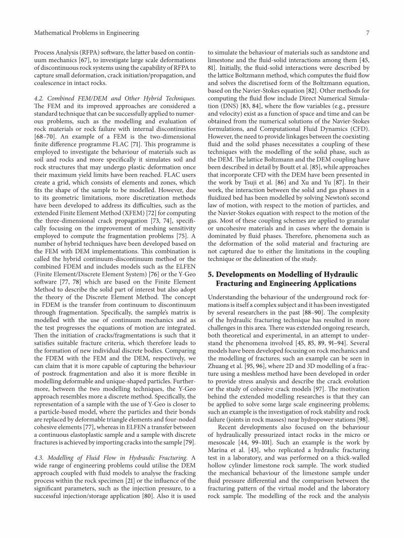
Recent developments also focused on the behaviourof hydraulically pressurized intact rocks in the micro ormesoscale [44, 99–101]. Such an example is the work byMarina et al. [43], who replicated a hydraulic fracturingtest in a laboratory, and was performed on a thick-walledhollow cylinder limestone rock sample. The work studiedthe mechanical behaviour of the limestone sample underfluid pressure differential and the comparison between thefracturing pattern of the virtual model and the laboratoryrock sample. The modelling of the rock and the analysis
8 Mathematical Problems in Engineering
Z
XY
(a)
X
Z
Y
(b)
Y
Z
X
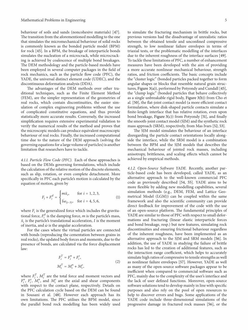
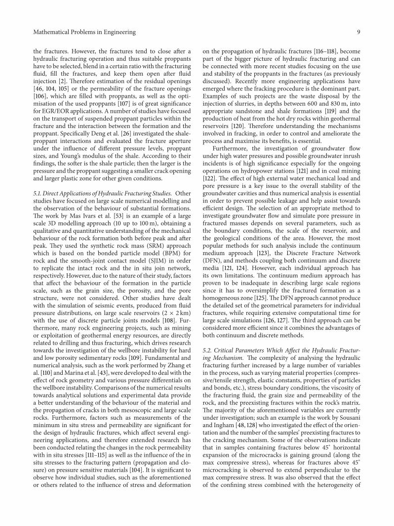
(c)Figure 4: (a) Schematic of the virtual limestone model with the use of the DEM approach, (b) application of the fluid cell grid around a sliceof the sample, and (c) fluid velocity vectors indicating the horizontal fluid movement from the outside surface towards the hollow core [43].
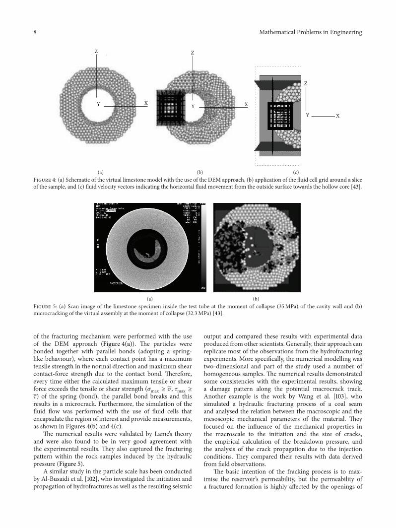
(a) (b)Figure 5: (a) Scan image of the limestone specimen inside the test tube at the moment of collapse (35MPa) of the cavity wall and (b)microcracking of the virtual assembly at the moment of collapse (32.3MPa) [43].
of the fracturing mechanism were performed with the useof the DEM approach (Figure 4(a)). The particles werebonded together with parallel bonds (adopting a spring-like behaviour), where each contact point has a maximumtensile strength in the normal direction and maximum shearcontact-force strength due to the contact bond. Therefore,every time either the calculated maximum tensile or shearforce exceeds the tensile or shear strength (𝜎max ≥ 𝜎, 𝜏max ≥𝜏) of the spring (bond), the parallel bond breaks and thisresults in a microcrack. Furthermore, the simulation of thefluid flow was performed with the use of fluid cells thatencapsulate the region of interest and providemeasurements,as shown in Figures 4(b) and 4(c).
The numerical results were validated by Lame’s theoryand were also found to be in very good agreement withthe experimental results. They also captured the fracturingpattern within the rock samples induced by the hydraulicpressure (Figure 5).
A similar study in the particle scale has been conductedby Al-Busaidi et al. [102], who investigated the initiation andpropagation of hydrofractures as well as the resulting seismic
output and compared these results with experimental dataproduced from other scientists. Generally, their approach canreplicate most of the observations from the hydrofracturingexperiments. More specifically, the numerical modelling wastwo-dimensional and part of the study used a number ofhomogeneous samples. The numerical results demonstratedsome consistencies with the experimental results, showinga damage pattern along the potential macrocrack track.Another example is the work by Wang et al. [103], whosimulated a hydraulic fracturing process of a coal seamand analysed the relation between the macroscopic and themesoscopic mechanical parameters of the material. Theyfocused on the influence of the mechanical properties inthe macroscale to the initiation and the size of cracks,the empirical calculation of the breakdown pressure, andthe analysis of the crack propagation due to the injectionconditions. They compared their results with data derivedfrom field observations.
The basic intention of the fracking process is to max-imise the reservoir’s permeability, but the permeability ofa fractured formation is highly affected by the openings of
Mathematical Problems in Engineering 9
the fractures. However, the fractures tend to close after ahydraulic fracturing operation and thus suitable proppantshave to be selected, blend in a certain ratio with the fracturingfluid, fill the fractures, and keep them open after fluidinjection [2]. Therefore estimation of the residual openings[46, 104, 105] or the permeability of the fracture openings[106], which are filled with proppants, as well as the opti-misation of the used proppants [107] is of great significancefor EGR/EOR applications. A number of studies have focusedon the transport of suspended proppant particles within thefracture and the interaction between the formation and theproppant. Specifically Deng et al. [26] investigated the shale-proppant interactions and evaluated the fracture apertureunder the influence of different pressure levels, proppantsizes, and Young’s modulus of the shale. According to theirfindings, the softer is the shale particle; then the larger is thepressure and the proppant suggesting a smaller crack openingand larger plastic zone for other given conditions.
5.1. Direct Applications of Hydraulic Fracturing Studies. Otherstudies have focused on large scale numerical modelling andthe observation of the behaviour of substantial formations.The work by Mas Ivars et al. [53] is an example of a largescale 3D modelling approach (10 up to 100m), obtaining aqualitative and quantitative understanding of the mechanicalbehaviour of the rock formation both before peak and afterpeak. They used the synthetic rock mass (SRM) approachwhich is based on the bonded particle model (BPM) forrock and the smooth-joint contact model (SJIM) in orderto replicate the intact rock and the in situ join network,respectively. However, due to the nature of their study, factorsthat affect the behaviour of the formation in the particlescale, such as the grain size, the porosity, and the porestructure, were not considered. Other studies have dealtwith the simulation of seismic events, produced from fluidpressure distributions, on large scale reservoirs (2 × 2 km)with the use of discrete particle joints models [108]. Fur-thermore, many rock engineering projects, such as miningor exploitation of geothermal energy resources, are directlyrelated to drilling and thus fracturing, which drives researchtowards the investigation of the wellbore instability for hardand low porosity sedimentary rocks [109]. Fundamental andnumerical analysis, such as the work performed by Zhang etal. [110] andMarina et al. [43], were developed to deal with theeffect of rock geometry and various pressure differentials onthe wellbore instability. Comparisons of the numerical resultstowards analytical solutions and experimental data providea better understanding of the behaviour of the material andthe propagation of cracks in both mesoscopic and large scalerocks. Furthermore, factors such as measurements of theminimum in situ stress and permeability are significant forthe design of hydraulic fractures, which affect several engi-neering applications, and therefore extended research hasbeen conducted relating the changes in the rock permeabilitywith in situ stresses [111–115] as well as the influence of the insitu stresses to the fracturing pattern (propagation and clo-sure) on pressure sensitive materials [104]. It is significant toobserve how individual studies, such as the aforementionedor others related to the influence of stress and deformation
on the propagation of hydraulic fractures [116–118], becomepart of the bigger picture of hydraulic fracturing and canbe connected with more recent studies focusing on the useand stability of the proppants in the fractures (as previouslydiscussed). Recently more engineering applications haveemerged where the fracking procedure is the dominant part.Examples of such projects are the waste disposal by theinjection of slurries, in depths between 600 and 830m, intoappropriate sandstone and shale formations [119] and theproduction of heat from the hot dry rocks within geothermalreservoirs [120]. Therefore understanding the mechanismsinvolved in fracking, in order to control and ameliorate theprocess and maximise its benefits, is essential.
Furthermore, the investigation of groundwater flowunder high water pressures and possible groundwater inrushincidents is of high significance especially for the ongoingoperations on hydropower stations [121] and in coal mining[122]. The effect of high external water mechanical load andpore pressure is a key issue to the overall stability of thegroundwater cavities and thus numerical analysis is essentialin order to prevent possible leakage and help assist towardsefficient design. The selection of an appropriate method toinvestigate groundwater flow and simulate pore pressure infractured masses depends on several parameters, such asthe boundary conditions, the scale of the reservoir, andthe geological conditions of the area. However, the mostpopular methods for such analysis include the continuummedium approach [123], the Discrete Fracture Network(DFN), and methods coupling both continuum and discretemedia [121, 124]. However, each individual approach hasits own limitations. The continuum medium approach hasproven to be inadequate in describing large scale regionssince it has to oversimplify the fractured formation as ahomogeneous zone [125].TheDFN approach cannot producethe detailed set of the geometrical parameters for individualfractures, while requiring extensive computational time forlarge scale simulations [126, 127]. The third approach can beconsidered more efficient since it combines the advantages ofboth continuum and discrete methods.
5.2. Critical Parameters Which Affect the Hydraulic Fractur-ing Mechanism. The complexity of analysing the hydraulicfracturing further increased by a large number of variablesin the process, such as varying material properties (compres-sive/tensile strength, elastic constants, properties of particlesand bonds, etc.), stress boundary conditions, the viscosity ofthe fracturing fluid, the grain size and permeability of therock, and the preexisting fractures within the rock’s matrix.The majority of the aforementioned variables are currentlyunder investigation; such an example is the work by Sousaniand Ingham [48, 128] who investigated the effect of the orien-tation and the number of the samples’ preexisting fractures tothe cracking mechanism. Some of the observations indicatethat in samples containing fractures below 45∘ horizontalexpansion of the microcracks is gaining ground (along themax compressive stress), whereas for fractures above 45∘microcracking is observed to extend perpendicular to themax compressive stress. It was also observed that the effectof the confining stress combined with the heterogeneity of
10 Mathematical Problems in Engineering
the material, due to fracture, affects the orientation of themicrocracking; finally, it was validated that extensive crackingis directly related to energy release, resulting in an increase ofthe kinetic energy within the sample.
Another example is the work performed by Martinez[129] who investigated the influence of varying materialproperties and boundary conditions in the microscale on thefracturingmechanismof poorly consolidated rock formation.Based on his overall results, he suggests that conventionaltheory ignores the mechanisms, such as shear cracking,which control the propagation of fractures with respect topoorly consolidated rocks and that the assumption of linearelastic behaviour of the material is not always dominantin Discrete Element Method (DEM) simulations. Moreexamples are the work by Shimizu et al. [130–132], whodealt with the effect of the fluid viscosity and the grainsize, to the behaviour of the hard rock. They observedthat in the case of a homogeneous material and the useof a high viscous fluid the breakdown pressure was muchhigher than in the case of heterogeneous material. Theirfindings can be attributed to the defects between grains,due to differences of grain size, which therefore trigger theinitiation of fracking. Their results were in agreement withlaboratory results [93, 133, 134] which show a decrease ofbreakdown pressure with increasing grain size. Also theyconcluded that when low fluid viscosity was used, the fracturepropagated along the direction of maximum compressivestress and the fluid penetrated directly into the fracture. Theopposite occurred in the case of high viscosity, where the fluidcannot penetrate into the fracture unless the latter propagatesfirst.
Other researchers have produced similar studies, suchas Ishida et al. [135, 136], who performed a set of similarhydraulic experiments (the same in situ stress and flowrate) in the laboratory, using low and high viscous fluids(water/oil and supercritical/liquid CO
2, resp.). The aim of
their study was to investigate the effect of fluid viscosity tothe breakdown pressure and compare the results from bothstudies. According to their findings they suggest that thesupercritical CO
2(sc-CO
2) tends to initiate cracks which
extend more three-dimensionally compared to the liquidCO2(l-CO
2) which generates cracks that extend in a fat
plane. The comparison between the aforementioned resultsand the acoustic emissions from the use of water andoil were observed to be distributed in a narrower region.Furthermore, they concluded that the breakdown pressureswere lower for the sc-CO
2than for the l-CO
2, while the
breakdown pressures produced from water and oil weresignificantly higher in comparison. Furthermore, Bruno [114]investigated the damage and the stress-induced permeabilityanisotropy in weakly cemented geological materials in themicroscopic level. His results are well compared with theacoustic emissions of experimental data, with the reductionscale of the stress-induced permeability being dependenton the relationship between the amount of intergranularbonds and the stress levels. Specifically, the fluid permeabilityis reduced for both low and near hydrostatic stress levels,whereas for high deviatoric stress levels the flow channelsincrease affecting the induced permeability reduction. An
overall anisotropy of the permeability is observed in themacroscopic level.
6. Conclusions
This paper provides a synopsis and an overview of thepast and recent developments of hydraulic fracturing, itsapplications, its possible hazards, and the available compu-tational methods for analysing this technique. Even thoughhydraulic fracturing has been extensively used for severaldecades as a method of exploiting energy sources, there isstill requirement for further research developments due tothe difficulty of understanding the complex undergroundmechanisms and the limitations of the availablemathematicalmodels.
A number of studies have focused on the possible haz-ardous behaviour of the fracking mechanism, both experi-mentally and numerically, with some of the topics includ-ing the contamination of shallow aquifers from flowbackfluids, poor well integrity, the effect of active faults andleakage pathways, and induced seismicity. The outcome ofthese works has resulted in the development of advancedmathematical models that can be successfully applied inreal world operations. The FEM has been widely used fornumerous engineering problems. However, its limitationshave led to other improved techniques, such as the DEM.The latter is an alternative approach that has become wellrecognized in this field since it is free from mesh sensitiv-ity compared to the FEM and can provide more accuratereproductions of materials in terms of inhomogeneities anddiscontinuities.
Modelling the failure mechanism of hard rocks is achallenging task and the presence of preexisting discon-tinuities (fractures, faults) makes the problem even morecomplex. This paper presents a review on the availablemathematical and computational models for simulating themechanical behaviour of rock formations and fluid flow, aswell as some critical studies and their fundamental outcome.Following the references provided in this paper, the readerscan access the detailed discussion and formulation of aspecific modelling approach. Even though scientists havedeveloped advancedmodelling techniques, such as the DEM,the XFEM, or the FDEM approaches, more research isrequired to fully understand the fracking mechanism. Areassuch as the modelling of rocks with preexisting fracturesunder injection conditions in the microscale and the effectof fracture orientation and different injection and reservoirconditions, the transition between the models in differentscales to improve the accuracy of modelling the field scalehydraulic fracturing process with the considerations andbenefits of the microscopic mechanisms, and the influ-ences of the chemical composition of the fracturing fluidsare some of the topics that need to be addressed in thefuture.
Conflict of Interests
The authors declare that there is no conflict of interestsregarding the publication of this paper.
Mathematical Problems in Engineering 11
Acknowledgments
Marina Sousani would like to thank the School of Civil Engi-neering and the School of Chemical and Process Engineering,University of Leeds, for sponsoring this research.
References
[1] G. C. Howard and C. R. Fast, Hydraulic Fracturing: Core Issues& Trends, vol. 5 of Mineral Law Series, Society of PetroleumEngineers, Houston, Tex, USA, 1970.
[2] M. J. Economides and T. Martin,Modern Fracturing—Enhanc-ing Natural Gas Production, BJ Services Company, Houston,Tex, USA, 2007.
[3] P. Kasza and K. Wilk, “Completion of shale gas formations byhydraulic fracturing,” Przemysl Chemiczny, vol. 91, no. 4, pp.608–612, 2012.
[4] J. Adachi, E. Siebrits, A. Peirce, and J. Desroches, “Computersimulation of hydraulic fractures,” International Journal of RockMechanics andMining Sciences, vol. 44, no. 5, pp. 739–757, 2007.
[5] K. I.-I and Y. Sheng, “Modelling erosion control in oil produc-tion wells,” World Academy of Science, Engineering & Technol-ogy, vol. 4, no. 47, pp. 937–941, 2010.
[6] M. Smith, D. Campbell, E. Mackay, and D. Polson, CO2
Aquifer Storage Site Evaluation and Monitoring: Understandingthe Challenges of CO
2Storage: Results of the CASSEM Project,
Scottish Carbon Capture and Storage, Edinburgh, UK, 2012.[7] M. J. Economides and K. G. Nolte, Reservoir Stimulation, John
Wiley & Sons, 2000.[8] M. Mikkelsen, M. Jørgensen, and F. C. Krebs, “The teraton
challenge. A review of fixation and transformation of carbondioxide,” Energy and Environmental Science, vol. 3, no. 1, pp. 43–81, 2010.
[9] IPCC,Historical Overview of Climate Change Science, Intergov-ernmental Panel on Climate Change, chapter 1, 2007.
[10] DECC,TheCarbon Plan: Delivering our Carbon Future, Depart-ment of Energy & Climate Change, London, UK, 2011.
[11] European Commission, “Energy efficiency plan 2011,” in Pro-ceedings of the Communication from the Commission to theEuropean Parliament, the Council, the European Economic andSocial Committee and the Committee of the Regions (COM ’11),p. 109, March 2011.
[12] European Commission, “Renewable energy: progressing to-wards the 2020 target,” in Proceedings of the Communicationfrom the Commission to the European Parliament and the Coun-cil (COM ’11), vol. 31, 2011.
[13] IPCC, Climate Change 2007: Mitigation. Contribution of Work-ing Group III to the Fourth Assessment Report of the Inter-governmental Panel on Climate Change, edited by B. Metz, O.R. Davidson, P. R. Bosch, P. Dave, L. A. Meyer, CambridgeUniversity Press, New York, USA; Intergovernmental Panel onClimate Change, Cambridge, UK, 2007.
[14] International Energy Agency, Technology Roadmap: CarbonCapture and Storage, IEA Publications, Paris, France, 2013.
[15] J. Gibbins and H. Chalmers, “Carbon capture and storage,”Energy Policy, vol. 36, no. 12, pp. 4317–4322, 2008.
[16] International Energy Agency, Gadgets and Gigawatts: Policyfor Energy Efficient Electronics, IEA Publications, Paris, France,2009.
[17] IPCC, Climate Change 2014: Mitigation of Climate Change,Intergovernmental Panel on Climate Change, Cambridge Uni-versity Press, New York, NY, USA, 2014.
[18] The Global CCS Institute,The Global Status of CCS, The GlobalCCS Institute, Melbourne, Australia, 2014.
[19] B.Metz, O. R. Davidson, H. Coninck, M. Loos, and L. A.Meyer,IPCC. Carbon Dioxide Capture and Storage, IntergovernmentalPanel on Climate Change, Cambridge University Press, NewYork, NY, USA, 2005.
[20] S. Holloway, “Carbon capture and geological storage,” Philo-sophical Transactions of the Royal Society of London Series A,Containing Papers of a Mathematical or Physical Character, vol.365, pp. 1095–1107, 2007.
[21] K. I.-I. Eshiet and Y. Sheng, “Carbon dioxide injection andassociated hydraulic fracturing of reservoir formations,” Envi-ronmental Earth Sciences, vol. 72, no. 4, pp. 1011–1024, 2014.
[22] BGS. DECC, The Carboniferous Bowland Shale Gas Study:Geology and Resource Estimation, Brirish Geological Survey(BGS), Department of Energy & Climate Change (DECC),London, UK, 2013.
[23] C. Taylor and D. Lewis, Getting Shale Gas Working, vol. 6,Institue of Directors (IoD), 2013.
[24] Economic Affairs Committee, The Economic Impact on UKEnergy Policy of Shale Gas and Oil, Economic Affairs Commit-tee, London, UK, 2014.
[25] M. E. Parker, J. P. Meyer, and S. R. Meadows, “Carbon dioxideenhanced oil recovery injection operations technologies (posterpresentation),” Energy Procedia, vol. 1, no. 1, pp. 3141–3148, 2009.
[26] S.Deng,H. Li, G.Ma,H.Huang, andX. Li, “Simulation of shale-proppant interaction in hydraulic fracturing by the discreteelement method,” International Journal of Rock Mechanics andMining Sciences, vol. 70, pp. 219–228, 2014.
[27] B. van der Meer, “Carbon dioxide storage in natural gas reser-voirs,”Oil & Gas Science and Technology, vol. 60, no. 3, pp. 527–536, 2005.
[28] C. Khan, R. Amin, and G. Madden, “Carbon dioxide injectionfor enhanced gas recovery and storage (reservoir simulation),”Egyptian Journal of Petroleum, vol. 22, no. 2, pp. 225–240, 2013.
[29] M. Blunt, F. J. Fayers, and F. M. Orr Jr., “Carbon dioxide inenhanced oil recovery,” Energy Conversion and Management,vol. 34, no. 9–11, pp. 1197–1204, 1993.
[30] H. Jin, L. Gao, L. Sheng, and R. Porter, Supporting early CarbonCapture Utilisation and Storage Development in Non-PowerIndustrial Sectors, Shaanxi Province, China, vol. 12, Centre forLow Carbon Futures, York, UK, 2012.
[31] E. Fjaer, R. M. Holt, A. M. Raaen, R. Risnes, and P. Horsrud,Petroleum Related Rock Mechanics. Developments in PetroleumScience, vol. 53, Elsevier, Amsterdam, The Netherlands, 2008.
[32] S. J. Wilkins and S. J. Naruk, “Quantitative analysis of slip-induced dilation with application to fault seal,” AAPG Bulletin,vol. 91, no. 1, pp. 97–113, 2007.
[33] J. Kaldi, R. Daniel, E. Tenthorey et al., Caprock Systems forGeological Storage, vol. 1, EAGHG, Cheltenham, UK, 2011.
[34] A. Kissinger, R. Helmig, A. Ebigbo et al., “Hydraulic fracturingin unconventional gas reservoirs: risks in the geological system,part 2,” Environmental Earth Sciences, vol. 70, no. 8, pp. 3855–3873, 2013.
[35] B. C. Gordalla, U. Ewers, and F. H. Frimmel, “Hydraulic frac-turing: a toxicological threat for groundwater and drinking-water?” Environmental Earth Sciences, vol. 70, no. 8, pp. 3875–3893, 2013.
[36] J. Riedl, S. Rotter, S. Faetsch, M. Schmitt-Jansen, and R. Al-tenburger, “Proposal for applying a component-based mixtureapproach for ecotoxicological assessment of fracturing fluids,”
12 Mathematical Problems in Engineering
Environmental Earth Sciences, vol. 70, no. 8, pp. 3907–3920,2013.
[37] O. Olsson, D. Weichgrebe, and K.-H. Rosenwinkel, “Hydraulicfracturing wastewater in Germany: composition, treatment,concerns,” Environmental Earth Sciences, vol. 70, no. 8, pp.3895–3906, 2013.
[38] T. Lange, M. Sauter, M. Heitfeld et al., “Hydraulic fracturingin unconventional gas reservoirs: risks in the geological systempart 1,” Environmental Earth Sciences, vol. 70, no. 8, pp. 3839–3853, 2013.
[39] COM, Exploration and Production of Hydrocarbons (Such asShale Gas) Using High Volume Hydraulic Fracturing in the EU,European Commission, Brussels, Belgium, 2014.
[40] C. Ewen, D. Borchardt, R. Hammerbacher, and S. Richter,Hydrofracking Risk Assessment, Panel of Experts, ExxonMobilProduction Deutschland, 2012.
[41] V. Sarhosis and Y. Sheng, “Identification of material parametersfor low bond strength masonry,” Engineering Structures, vol. 60,pp. 100–110, 2014.
[42] M. E. Hanson, G. D. Anderson, and R. J. Shaffer, “Theoreticaland experimental research on hydraulic fracturing,” Journal ofEnergy Resources Technology, vol. 102, no. 2, pp. 92–98, 1980.
[43] S. Marina, E. K. Imo-Imo, I. Derek, P. Mohamed, and S. Yong,“Modelling of hydraulic fracturing process by coupled discreteelement and fluid dynamic methods,” Environmental EarthSciences, vol. 72, no. 9, pp. 3383–3399, 2014.
[44] K. I. Eshiet, Y. Sheng, and J. Ye, “Microscopic modelling ofthe hydraulic fracturing process,” Environmental Earth Sciences,vol. 68, no. 4, pp. 1169–1186, 2013.
[45] D. O. Potyondy and P. A. Cundall, “A bonded-particle modelfor rock,” International Journal of Rock Mechanics & MiningSciences, vol. 41, no. 8, pp. 1329–1364, 2004.
[46] L. Bortolan Neto and A. Kotousov, “Residual opening ofhydraulically stimulated fractures filled with granular particles,”Journal of Petroleum Science and Engineering, vol. 100, pp. 24–29, 2012.
[47] P. A. Cundall and O. D. L. Strack, “Discrete numerical modelfor granular assemblies,” Geotechnique, vol. 29, no. 1, pp. 47–65,1979.
[48] M. Sousani, D. Ingham, M. Pourkashanian, Y. Sheng, and I.-I. K. Eshiet, “Simulation of the hydraulic fracturing process offractured rocks by the discrete elementmethod,” EnvironmentalEarth Sciences, vol. 73, no. 12, pp. 8451–8469, 2015.
[49] A. Lisjak and G. Grasselli, “A review of discrete modeling tech-niques for fracturing processes in discontinuous rock masses,”Journal of Rock Mechanics and Geotechnical Engineering, vol. 6,no. 4, pp. 301–314, 2014.
[50] N.Cho, C.D.Martin, andD.C. Sego, “A clumped particlemodelfor rock,” International Journal of Rock Mechanics and MiningSciences, vol. 44, no. 7, pp. 997–1010, 2007.
[51] D. O. Potyondy, “A flat-jointed bonded-particle material forhard rock,” in Proceedings of the 46th US Rock Mechan-ics/Geomechanics Symposium, Chicago, Ill, USA, January 2012.
[52] D. Mas Ivars, Bonded particle model for jointed rock, KTH RoyalInstitute of Technology, Stockolm, Sweden, 2010.
[53] D. Mas Ivars, M. E. Pierce, C. Darcel et al., “The synthetic rockmass approach for jointed rock mass modelling,” InternationalJournal of Rock Mechanics and Mining Sciences, vol. 48, no. 2,pp. 219–244, 2011.
[54] J. Kozicki and F. V. Donze, “A new open-source softwaredeveloped for numerical simulations using discrete modeling
methods,” Computer Methods in Applied Mechanics and Engi-neering, vol. 197, no. 49-50, pp. 4429–4443, 2008.
[55] J. Kozicki and F. V. Donze, “YADE−OPEN DEM: an open-source software using a discrete element method to simulategranular material,” Engineering Computations, vol. 26, no. 7, pp.786–805, 2009.
[56] L. Scholtes and F.-V. Donze, “Modelling progressive failure infractured rock masses using a 3D discrete element method,”International Journal of Rock Mechanics and Mining Sciences,vol. 52, pp. 18–30, 2012.
[57] L. Scholtes and F.-V. Donze, “A DEM model for soft and hardrocks: role of grain interlocking on strength,” Journal of theMechanics and Physics of Solids, vol. 61, no. 2, pp. 352–369, 2013.
[58] L. Scholtes, F.-V. Donze, and M. Khanal, “Scale effects onstrength of geomaterials, case study: coal,” Journal of theMechanics and Physics of Solids, vol. 59, no. 5, pp. 1131–1146, 2011.
[59] B. Harthong, L. Scholtes, and F.-V. Donze, “Strength charac-terization of rock masses, using a coupled DEM-DFN model,”Geophysical Journal International, vol. 191, no. 2, pp. 467–480,2012.
[60] S. C. Fan, Y. Y. Jiao, and J. Zhao, “On modelling of incidentboundary for wave propagation in jointed rock masses usingdiscrete element method,” Computers and Geotechnics, vol. 31,no. 1, pp. 57–66, 2004.
[61] X. B. Zhao, J. Zhao, J. G. Cai, and A. M. Hefny, “UDEC mod-elling on wave propagation across fractured rock masses,”Computers and Geotechnics, vol. 35, no. 1, pp. 97–104, 2008.
[62] L. J. Lorig and P. A. Cundall, “Modeling of reinforced concreteusing the distinct element method,” in Fracture of Concrete andRock, S. Shah and S. Swartz, Eds., pp. 276–287, Springer, NewYork, NY, USA, 1989.
[63] M. Christianson, M. Board, and D. Rigby, “UDEC simulationof triaxial testing of lithophysal tuff,” in Proceedings of the 41stUS Symposium on Rock Mechanics (USRMS ’06), Golden, Colo,USA, June 2006.
[64] B. Damjanac, M. Board, M. Lin, D. Kicker, and J. Leem,“Mechanical degradation of emplacement drifts at YuccaMountain—a modeling case study. Part II: lithophysal rock,”International Journal of Rock Mechanics and Mining Sciences,vol. 44, no. 3, pp. 368–399, 2007.
[65] G. Shi and R. E. Goodman, “Discontinuous deformationanalysis—a newmethod for computing stress, strain and slidingof block systems,” in Proceedings of the 29th US Symposium onRock Mechanics (USRMS ’88), Minneapolis, Minn, USA, 1988.
[66] C. A. Tang and H. Y. Lu, “The DDD method based oncombination of RFPA,” in Frontiers of Discontinuous NumericalMethods and Practical Simulations in Engineering and DisasterPrevention, G. Chen, Y. Ohnishi, L. Zheng, and T. Sasaki, Eds.,pp. 105–112, CRC Press, 2013.
[67] C. Tang, “Numerical simulation of progressive rock failure andassociated seismicity,” International Journal of Rock Mechanicsand Mining Sciences, vol. 34, no. 2, pp. 249–261, 1997.
[68] T. Belytschko and T. Black, “Elastic crack growth in finiteelements with minimal remeshing,” International Journal forNumerical Methods in Engineering, vol. 45, no. 5, pp. 601–620,1999.
[69] N.Moes, J. Dolbow, andT. Belytschko, “A finite elementmethodfor crack growth without remeshing,” International Journal forNumerical Methods in Engineering, vol. 46, no. 1, pp. 131–150,1999.
Mathematical Problems in Engineering 13
[70] V. Giamundo, V. Sarhosis, G. P. Lignola, Y. Sheng, and G.Manfredi, “Evaluation of different computational modellingstrategies for the analysis of low strength masonry structures,”Engineering Structures, vol. 73, pp. 160–169, 2014.
[71] Itasca Consulting Group, Lagrangian Analysis of Continua(FLAC), ICG, Minneapolis, Minn, USA, 5th edition, 2005.
[72] J.-H. Song, P. Lea, and J. Oswald, “Explicit dynamic finiteelement method for predicting implosion/explosion inducedfailure of shell structures,” Mathematical Problems in Engineer-ing, vol. 2013, Article ID 957286, 11 pages, 2013.
[73] P. M. A. Areias and T. Belytschko, “Analysis of three-dimen-sional crack initiation and propagation using the extended finiteelement method,” International Journal for Numerical Methodsin Engineering, vol. 63, no. 5, pp. 760–788, 2005.
[74] Q. Duan, J.-H. Song, T. Menouillard, and T. Belytschko,“Element-local level setmethod for three-dimensional dynamiccrack growth,” International Journal for Numerical Methods inEngineering, vol. 80, no. 12, pp. 1520–1543, 2009.
[75] Y. Cai, X. Zhuang, and C. Augarde, “A new partition of unityfinite element free from the linear dependence problem andpossessing the delta property,” Computer Methods in AppliedMechanics and Engineering, vol. 199, no. 17–20, pp. 1036–1043,2010.
[76] Rockfield Software, ELFEN 2D/3D Numerical Modelling Pack-age, Rockfield Software, Swansea, UK, 2004.
[77] A. Munjiza, K. R. F. Andrews, and J. K. White, “Combinedsingle and smeared crack model in combined finite-discreteelement analysis,” International Journal for Numerical Methodsin Engineering, vol. 44, no. 1, pp. 41–57, 1999.
[78] A. Munjiza, The Combined Finite-Discrete Element Method,John Wiley & Sons, Chichester, UK, 2004.
[79] D.R. J.Owen andY.T. Feng, “Parallelised finite/discrete elementsimulation of multi-fracturing solids and discrete systems,”Engineering Computations, vol. 18, no. 3-4, pp. 557–576, 2001.
[80] J. Rutqvist, J. Birkholzer, F. Cappa, and C.-F. Tsang, “Estimatingmaximum sustainable injection pressure during geologicalsequestration of CO
2using coupled fluid flow and geomechani-
cal fault-slip analysis,” Energy Conversion andManagement, vol.48, no. 6, pp. 1798–1807, 2007.
[81] K. Walton, “The effective elastic moduli of a random packing ofspheres,” Journal of the Mechanics and Physics of Solids, vol. 35,no. 2, pp. 213–226, 1987.
[82] S. Chen and G. D. Doolen, “Lattice boltzmannmethod for fluidflows,” Annual Review of Fluid Mechanics, vol. 30, pp. 329–364,1998.
[83] S. Dong, “Direct numerical simulation of turbulent Taylor—Couette flow,” Journal of Fluid Mechanics, vol. 587, pp. 373–393,2007.
[84] P. Moin and K. Mahesh, “Direct numerical simulation: a tool inturbulence research,”Annual Review of FluidMechanics, vol. 30,pp. 539–578, 1998.
[85] D. F. Boutt, B. K. Cook, B. J. O. L.McPherson, and J. R.Williams,“Direct simulation of fluid-solid mechanics in porous mediausing the discrete element and lattice-Boltzmann methods,”Journal of Geophysical Research: Solid Earth, vol. 112, no. 10, pp.1–13, 2007.
[86] Y. Tsuji, T. Kawaguchi, and T. Tanaka, “Discrete particle simula-tion of two-dimensional fluidized bed,” Powder Technology, vol.77, no. 1, pp. 79–87, 1993.
[87] B. H. Xu and A. B. Yu, “Numerical simulation of the gas-solidflow in a fluidized bed by combining discrete particle method
with computational fluid dynamics,” Chemical Engineering Sci-ence, vol. 52, no. 16, pp. 2785–2809, 1997.
[88] R. T. Ewy, G. W. Cook, and L. R. Myer, “Hollow cylindertests for studying fracture around underground openings,” inProceedings of the 29th US Symposium on Rock Mechanics(USRMS ’88), Minneapolis, Minn, USA, June 1988.
[89] M. E. Hanson, G. D. Anderson, R. J. Shaffer, and L. D.Thorson,“Some effects of stress, friction, and fluid flow on hydraulicfracturing,” Society of Petroleum Engineers Journal, vol. 22, no.3, 1982.
[90] P. A. Cundall, “A computer model for simulating progressive,large-scale movements in blocky rock systems,” in Proceedingsof the Symposium of International Society of RockMechanics, vol.1, Nancy, France, 1971.
[91] S. C. Blair, R. K. Thorpe, F. E. Heuze, and R. J. Shaffer, “Lab-oratory observations of the effect of geologic discontinuitieson hydrofracture propagation,” in Proceedings of the 30th USSymposium on Rock Mechanics (USRMS ’98), Morgantown,WVa, USA, January 1989.
[92] Q. Fang and Y. Li, “Exhaustive brine production and completeCO2storage in Jianghan Basin of China,” Environmental Earth
Sciences, vol. 72, no. 5, pp. 1541–1553, 2014.[93] I. Matsunaga, H. Kobayashi, S. Sasaki, and T. Ishida, “Studying
hydraulic fracturing mechanism by laboratory experimentswith acoustic emission monitoring,” International Journal ofRockMechanics andMining Sciences & Geomechanics Abstracts,vol. 30, no. 7, pp. 909–912, 1993.
[94] M. Zeidouni, J.-P. Nicot, and S. D.Hovorka, “Monitoring above-zone temperature variations associated with CO
2and brine
leakage from a storage aquifer,” Environmental Earth Sciences,vol. 72, no. 5, pp. 1733–1747, 2014.
[95] X. Zhuang, C. E. Augarde, and K. M. Mathisen, “Fracture mod-eling using meshless methods and level sets in 3D: frameworkand modeling,” International Journal for Numerical Methods inEngineering, vol. 92, no. 11, pp. 969–998, 2012.
[96] X. Zhuang, C. Augarde, and S. Bordas, “Accurate fracturemodelling using meshless methods, the visibility criterion andlevel sets: formulation and 2Dmodelling,” International Journalfor Numerical Methods in Engineering, vol. 86, no. 2, pp. 249–268, 2011.
[97] G. Zi and T. Belytschko, “New crack-tip elements for XFEMand applications to cohesive cracks,” International Journal forNumericalMethods in Engineering, vol. 57, no. 15, pp. 2221–2240,2003.
[98] H. Zhu, X. Zhuang, Y. Cai, andG.Ma, “High rock slope stabilityanalysis using the enriched meshless shepard and least squaresmethod,” International Journal of Computational Methods, vol.8, no. 2, pp. 209–228, 2011.
[99] B. C. Haimson, “Hydraulic fracturing and rock characteri-zation,” International Journal of Rock Mechanics and MiningSciences, vol. 41, supplement 1, pp. 188–194, 2004.
[100] F. Hamidi and A. Mortazavi, “A new three dimensionalapproach to numerically model hydraulic fracturing process,”Journal of Petroleum Science and Engineering, vol. 124, pp. 451–467, 2014.
[101] N. Nagel, I. Gil, M. Sanchez-Nagel, and B. Damjanac, “Simu-lating hydraulic fracturing in real fractured rocks—overcomingthe limits of Pseudo3D models,” in Proceedings of the SPEHydraulic Fracturing Technology Conference, The Woodlands,Texas, USA, January 2011.
[102] A. Al-Busaidi, J. F. Hazzard, and R. P. Young, “Distinct elementmodeling of hydraulically fractured Lac du Bonnet granite,”
14 Mathematical Problems in Engineering
Journal of Geophysical Research: Solid Earth, vol. 110, Article IDB06302, 2005.
[103] T. Wang, W. Zhou, J. Chen, X. Xiao, Y. Li, and X. Zhao,“Simulation of hydraulic fracturing using particle flow methodand application in a coal mine,” International Journal of CoalGeology, vol. 121, pp. 1–13, 2014.
[104] P. Papanastasiou, “Hydraulic fracture closure in a pressure-sensitive elastoplastic medium,” International Journal of Frac-ture, vol. 103, no. 2, pp. 149–161, 2000.
[105] D. B. van Dam, C. J. de Pater, and R. Romijn, “Analysisof hydraulic fracture closure in laboratory experiments,” SPEProduction & Facilities, vol. 15, no. 3, pp. 151–158, 2000.
[106] A. Khanna, A. Kotousov, J. Sobey, and P. Weller, “Conductivityof narrow fractures filled with a proppant monolayer,” Journalof Petroleum Science and Engineering, vol. 100, pp. 9–13, 2012.
[107] M. C. Vincent, “Proving it—a review of 80 published fieldstudies demonstrating the importance of increased fractureconductivity,” in Proceedings of the SPE Annual Technical Con-ference and Exhibition, San Antonio, Tex, USA, 2002.
[108] J. S. Yoon, A. Zang, and O. Stephansson, “Numerical investiga-tion on optimized stimulation of intact and naturally fractureddeep geothermal reservoirs using hydro-mechanical coupleddiscrete particles joints model,” Geothermics, vol. 52, pp. 165–184, 2014.
[109] J. C. Jaeger, N. G. W. Cook, and R. W. Zimmerman, Funda-mentals of Rock Mechanics, Wiley-Blackwell, Oxford, UK, 4thedition, 2007.
[110] X. Zhang, N. Last, W. Powrie, and R. Harkness, “Numericalmodelling of wellbore behaviour in fractured rock masses,”Journal of Petroleum Science and Engineering, vol. 23, no. 2, pp.95–115, 1999.
[111] R. M. Holt, “Permeability reduction induced by a non-hydro-static stress field,” SPE Formation Evaluation, vol. 5, no. 4, pp.444–448, 1990.
[112] S. Bachu and B. Bennion, “Effects of in-situ conditions onrelative permeability characteristics of CO
2-brine systems,”
Environmental Geology, vol. 54, no. 8, pp. 1707–1722, 2008.[113] M. J. Bouteca, J. P. Sarda, and O. Vincke, “Constitutive law
for permeability evolution of sandstones during depletion,” inProceedings of the SPE International Symposium on FormationDamage Control, Lafayette, La, USA, 2000.
[114] M. S. Bruno, “Micromechanics of stress-induced permeabilityanisotropy and damage in sedimentary rock,” Mechanics ofMaterials, vol. 18, no. 1, pp. 31–48, 1994.
[115] S. L. Bryant, P. R. King, and D. W. Mellor, “Network modelevaluation of permeability and spatial correlation in a realrandom sphere packing,” Transport in Porous Media, vol. 11, no.1, pp. 53–70, 1993.
[116] J. Desroches andM.Thiercelin, “Modelling the propagation andclosure of micro-hydraulic fractures,” International Journal ofRockMechanics andMining Sciences & Geomechanics Abstracts,vol. 30, no. 7, pp. 1231–1234, 1993.
[117] D. Bigoni and E. Radi, “Mode I crack propagation in elastic-plastic pressure-sensitive materials,” International Journal ofSolids and Structures, vol. 30, no. 7, pp. 899–919, 1993.
[118] D. B. van Dam, C. J. de Pater, and R. Romijn, “Analysisof hydraulic fracture closure in laboratory experiments,” SPEProduction & Facilities, vol. 15, no. 3, pp. 151–158, 2000.
[119] N. R. F. Warpinski, P. T. F. Branagan, K. D. F. Mahrer, S. L. F.Wolhart, and Z. A. F. Moschovidis, “Microseismic monitoringof the Mounds drill cuttings injection tests,” in Proceedings of
the 37th US Symposium on Rock Mechanics (USRMS ’99), Vail,Colo, USA, 1999.
[120] A. S. P. Green, R. Baria, A. Madge, and R. Jones, “Fault-plane analysis of microseismicity induced by fluid injectionsinto granite,” Geological Society, London, Engineering GeologySpecial, vol. 5, no. 1, pp. 415–422, 1988.
[121] H.Wang, E.Wang, and K. Tian, “Amodel coupling discrete andcontinuum fracture domains for groundwater flow in fracturedmedia,” Journal of Hydraulic Research, vol. 42, supplement 1, pp.45–52, 2004.
[122] Q. Wu, Y. Liu, D. Liu, and W. Zhou, “Prediction of floor waterinrush: the application of GIS-based AHP vulnerable indexmethod to donghuantuo coalmine, China,”RockMechanics andRock Engineering, vol. 44, no. 5, pp. 591–600, 2011.
[123] B. Zhu, Q. Wu, J. Yang, and T. Cui, “Study of pore pressurechange during mining and its application on water inrushprevention: a numerical simulation case in Zhaogezhuangcoalmine, China,” Environmental Earth Sciences, vol. 71, no. 5,pp. 2115–2132, 2014.
[124] Y. Huang, Z. Zhou, J. Wang, and Z. Dou, “Simulation ofgroundwater flow in fractured rocks using a coupled modelbased on themethod of domain decomposition,”EnvironmentalEarth Sciences, vol. 72, no. 8, pp. 2765–2777, 2014.
[125] S. P. Neuman, “Trends, prospects and challenges in quantifyingflow and transport through fractured rocks,” HydrogeologyJournal, vol. 13, no. 1, pp. 124–147, 2005.
[126] A. Woodbury and K. Zhang, “Lanczos method for the solutionof groundwater flow in discretely fractured porous media,”Advances in Water Resources, vol. 24, no. 6, pp. 621–630, 2001.
[127] B. Berkowitz, “Characterizing flow and transport in fracturedgeological media: a review,” Advances in Water Resources, vol.25, no. 8–12, pp. 861–884, 2002.
[128] M. Sousani, Modeling of Hydraulic Fracturing in Rocks: AMultiscale and Fluid-Solid Coupling Approach, University ofLeeds, Leeds, UK, 2015.
[129] D. Martinez, Fundamental hydraulic fracturing concepts forpoorly consolitated formations [Ph.D. thesis], University of Okla-homa, Ann Arbor, Mich, USA, 2012.
[130] H. Shimizu, S. Murata, and T. Ishida, “The distinct elementanalysis for hydraulic fracturing in hard rock considering fluidviscosity and particle size distribution,” International Journal ofRock Mechanics and Mining Sciences, vol. 48, no. 5, pp. 712–727,2011.
[131] H. Shimizu, S. Murata, T. Ito, and T. Ishida, “The distinctelement analysis for hydraulic fracturing in unconsolidatedsand considering fluid viscosity,” in Proceedings of the 7th AsianRock Mechanics Symposium, January 2012.
[132] H. Shimizu, S. Murata, and T. Ishida, “The distinct elementanalysis for hydraulic fracturing considering the fluid viscosity,”in Proceedings of the 43rd US Rock Mechanics Symposium & 4thUS-Canada Rock Mechanics Symposium, Asheville, NC, USA,June 2009.
[133] T. Ishida, S. Sasaki, I. Matsunaga, Q. Chen, and Y. Mizuta,“Effect of grain size in granitic rocks on hydraulic fracturingmechanism,” in Trends in Rocks Mechanics: Proceedings ofSessions of Geo-Denver, GSP, Ed., pp. 128–139, American Societyof Civil Engineers, Denver, Colo, USA, 2000.
[134] T. Ishida, “Acoustic emissionmonitoring of hydraulic fracturingin laboratory and field,” Construction and Building Materials,vol. 15, no. 5-6, pp. 283–295, 2001.
Mathematical Problems in Engineering 15
[135] T. Ishida, K. Aoyagi, T. Niwa et al., “Acoustic emission mon-itoring of hydraulic fracturing laboratory experiment withsupercritical and liquid CO
2,” Geophysical Research Letters, vol.
39, no. 16, Article ID L16309, 2012.[136] T. Ishida, Q. Chen, Y. Mizuta, and J.-C. Roegiers, “Influence of
fluid viscosity on the hydraulic fracturing mechanism,” Journalof Energy Resources Technology, vol. 126, no. 3, 11 pages, 2004.
[137] SCCS, Opportunities for CO2Storage Around Scotland: An
Integraded Research Study, Scottish Centre for Carbon Storage,Scotprint, Edinburgh, UK, 2009.
[138] Royal Society R, Shale Gas Extraction in the UK: A Review ofHydraulic Fracturing, DES2597, The Royal Society, The RoyalAcademy of Engineering, London, UK, 2012.
[139] Itasca Consulting Group, Theory and Background 2: Contactmodels, ICG, Minneapolis, Minn, USA, 2008.

Submit your manuscripts athttp://www.hindawi.com
Hindawi Publishing Corporationhttp://www.hindawi.com Volume 2014
MathematicsJournal of
Hindawi Publishing Corporationhttp://www.hindawi.com Volume 2014
Mathematical Problems in Engineering
Hindawi Publishing Corporationhttp://www.hindawi.com
Differential EquationsInternational Journal of
Volume 2014
Applied MathematicsJournal of
Hindawi Publishing Corporationhttp://www.hindawi.com Volume 2014
Probability and StatisticsHindawi Publishing Corporationhttp://www.hindawi.com Volume 2014
Journal of
Hindawi Publishing Corporationhttp://www.hindawi.com Volume 2014
Mathematical PhysicsAdvances in
Complex AnalysisJournal of
Hindawi Publishing Corporationhttp://www.hindawi.com Volume 2014
OptimizationJournal of
Hindawi Publishing Corporationhttp://www.hindawi.com Volume 2014
CombinatoricsHindawi Publishing Corporationhttp://www.hindawi.com Volume 2014
International Journal of
Hindawi Publishing Corporationhttp://www.hindawi.com Volume 2014
Operations ResearchAdvances in
Journal of
Hindawi Publishing Corporationhttp://www.hindawi.com Volume 2014
Function Spaces
Abstract and Applied AnalysisHindawi Publishing Corporationhttp://www.hindawi.com Volume 2014
International Journal of Mathematics and Mathematical Sciences
Hindawi Publishing Corporationhttp://www.hindawi.com Volume 2014
The Scientific World JournalHindawi Publishing Corporation http://www.hindawi.com Volume 2014
Hindawi Publishing Corporationhttp://www.hindawi.com Volume 2014
Algebra
Discrete Dynamics in Nature and Society
Hindawi Publishing Corporationhttp://www.hindawi.com Volume 2014
Hindawi Publishing Corporationhttp://www.hindawi.com Volume 2014
Decision SciencesAdvances in
Discrete MathematicsJournal of
Hindawi Publishing Corporationhttp://www.hindawi.com
Volume 2014 Hindawi Publishing Corporationhttp://www.hindawi.com Volume 2014
Stochastic AnalysisInternational Journal of