review article fabrication, modification, and emerging applications of nanotube...
TRANSCRIPT

Hindawi Publishing CorporationInternational Journal of PhotoenergyVolume 2013, Article ID 761971, 19 pageshttp://dx.doi.org/10.1155/2013/761971
Review ArticleFabrication, Modification, and Emerging Applications ofTiO2 Nanotube Arrays by Electrochemical Synthesis: A Review
Jian-Ying Huang,1 Ke-Qin Zhang,1 and Yue-Kun Lai1,2
1 National Engineering Laboratory of Modern Silk, College of Textile and Clothing Engineering, Soochow University,Suzhou 215123, China
2 Physikalisches Institute and Center for Nanotechnology (CeNTech), Westfalische Wilhelms-Universitat Munster,48149 Munster, Germany
Correspondence should be addressed to Yue-Kun Lai; [email protected]
Received 9 July 2013; Accepted 30 July 2013
Academic Editor: Jiaguo Yu
Copyright © 2013 Jian-Ying Huang et al. This is an open access article distributed under the Creative Commons AttributionLicense, which permits unrestricted use, distribution, and reproduction in any medium, provided the original work is properlycited.
Titania nanotube arrays (TNAs) as a hot nanomaterial have a unique highly ordered array structure and good mechanical andchemical stability, as well as excellent anticorrosion, biocompatible, and photocatalytic performance. It has been fabricated by afacile electrochemical anodization in electrolytes containing small amounts of fluoric ions. In combination with our research work,we review the recent progress of the new research achievements of TNAs on the preparation processes, forming mechanism, andmodification. In addition, we will review the potential and significant applications in the photocatalytic degradation of pollutants,solar cells, water splitting, and other aspects. Finally, the existing problems and further prospects of this renascent and rapidlydeveloping field are also briefly addressed and discussed.
1. Introduction
Nanostructured materials with peculiar properties are notexpected in bulk phase and have already led to a break-through in various fields of science and technology. More-over, much of the current interest in one-dimensionalnanostructures, such as nanotube, nanowire, nanorod, andnanobelts, was initiated by the discovery of carbon nanotubesby Iijima et al. in 1991 [1]. Within these nanostructure materi-als, TiO
2-based nanotubes attracted engrossing interest and
intensive researches due to their merits of high specific sur-face area, ion-changeable ability, and photocatalytic ability.Over the past decades, nanostructured materials derivedfrom TiO
2have extensively been investigated for many
promising applications, including solar cells/batteries, self-cleaning coatings, electroluminescent hybrid devices, andphotocatalysis, owing to their peculiar chemical and physicalbehaviors. Currently, developedmethods of fabricatingTiO
2-
based nanotubes comprise the assisted-template method[2, 3], hydrothermal treatment [4–6], and electrochemicalanodic oxidation [7–10]. Each fabricationmethod has unique
advantages and functional features and comparisons amongthese approaches. Regarding the template-assisted method,anodic aluminum oxide (AAO) nanoporous membrane,which consists of an array of parallel straight nanopores withcontrollable diameter and length, is usually used as template.However, the template-assisted method often encountersdifficulties of prefabrication and postremoval of the previoustemplates and usually results in impurities. Concerninghydrothermal treatment, the self-assembled TiO
2nanotubes
are based on the treatment of Ti foils or TiO2powders in a
tightly closed vessel containing highly concentrated NaOHsolution (5–10M) to obtain TiO
2nanotube layer or TiO
2-
based powder [6, 11]. These methods, other than the electro-chemical anodic oxidation, are either not suitable for rapidproduction or notable to yield uniform TiO
2nanotubes with
vertical alignment. The demonstrated architecture of TiO2
nanotube arrays (TNAs) by a facile electrochemical anodiz-ing process is capable of an ordered alignment with highaspect ratio and establishment of pure-phase TiO
2structure
in one step under ambient environment. More importantly,the electrochemical anodization technique allows the growth

2 International Journal of Photoenergy
(a) (b)
(c) (d)
Morphology of TiO2 nanotube arrays (TNAs):
2001
2003
2005
2007
2010
Short and rough TNAs
Tapered, conical-shaped TNAs
(1) High-aspect-ratio ofTNA in neutral electrolyte(2) Smooth TNA anodized
in organic electrolyte (3) Transparent TNAs onconducting glass
(1) Free-standing and open-ended TNAs(2) Highly oedered TNAs bymulti-steps anodization
(3) Random TNAs with smalldiameter in F-ions free electrolyte
TNAs with a sub-micrometersize in diameter
Year
(e)
Figure 1: SEM images of TNA layers grown with different electrolytes. (a) Typical morphology obtained in acidic fluoride or HF electrolytes,(b) glycerol/fluoride electrolytes, and (c) ethylene glycol/fluoride electrolytes containing small amount of water. The insets show top views,bottom views, and side walls in detail. (d) Fluoride ions free electrolyte; these tubes grow in disordered bundles within seconds at comparablyhigh anodic potentials. (e) Morphology of new type TNAs with time.
of other oxides with self-ordering nanostructures for severaltransitional and valve metals, such as Al, Zr, Hf, Nb, Ta, W,and Fe and their alloys TiAl, TiZr, TiNb, Ti
6Al4V, and so on
[8, 10].In 1999, Zwilling et al. firstly reported the self-ordered
TiO2nanostructures by a simple electrochemical anodizing
process in a fluoride electrolyte [12]. Since then, severalanodizing approaches, mainly focused on finding the optimalelectrolyte and experimental parameters, have been exploredto efficiently achieve high quality self-organized TNAs(Figure 1) [13–18], such as short and roughTNAs [13], taperedand conical-shaped TNAs [18], smooth and high-aspect-ratioTNAs [16, 17], transparent TNAs [19, 20], free-standing and
open-endedTNAs [21, 22], highly ordered TNAs bymultistepanodization [23, 24], and TNAs with a submicrometer size indiameter [25, 26]. These results demonstrated that structureand morphology of TNAs, including tube diameter, length,wall thickness, and crystallinity, can be controlled by adjust-ing key parameters such as composition/shape of Ti substrate,electrolyte, pH, temperature, anodization voltage, current,and anodization time. It is, therefore, essential to understandthe various factors influencing the characterizations of as-prepared amorphous TNAs. Also, it should be noted thateither the annealing posttreatment or the modification ofTiO2-based nanotubes would dominate the corresponding
features and the performance of TiO2-based devices.The aim

International Journal of Photoenergy 3
2003 2004 2005 2006 2007 2008 2009 2010 2011 2012 2013Publishing year
800
700
600
500
400
300
200
100
0
Num
ber o
f pap
ers
(a)
2003 2004 2005 2006 2007 2008 2009 2010 2011 2012 2013
16000
14000
12000
10000
8000
6000
4000
2000
0
Cita
tions
Publishing year
(b)
Figure 2:The number of articles (a) published on TNAs formed by electrochemical anodization and corresponding aggregated citations (b).(Statistics analysis was obtained fromweb of science database onMay 30, 2013). Topic: TiO
2nanotube, with the exclusion of nanotube formed
by hydrothermal, sol-gel, and template or carbon nanotube.
is to make the material more suitable for various applicationsthat rely on specific electrical, optical, or chemical properties.In view of electronic properties, annealing to a crystallinestructure mainly changes the conductivity and lifetime ofcharge carriers, while modification with active doping orband gap engineering by introducing other elements targetsfor the decreasing of the optical band gap, thus enabling avisible-light photoresponse [27].
Based on extensive literatures with regard to self-orderedTNAs, the authors have categorized three broad groups,preparation and formation mechanism, modifications, andapplications, which are further subdivided according totheir pertinent studies. First, the formation mechanisms andphenomenon of the electrochemical formation of nanoporesand nanotubes by a self-ordering process are explained.Among the aforementioned experimental parameters, bothelectrolyte and anodizing voltage will be focused on anddiscussed. Then properties and modification of the TNAmaterials are addressed briefly, including technique examplesof doping, noble metal decoration, and semiconductor com-posite which are to be discussed. Finally, the current stage ofknowledge and recent studies on their potential applications,such as photocatalysis, solar cell, water splitting, and otheraspects are introduced. Analysis of the physicochemicalproperties and recent advances in their modification andapplications allow the identification of gaps in our knowledgeand highlight the need for critical studies in the area ofTNAs.
2. Electrochemical Anodization of TNAs
This section presents recent developments on preparationof self-ordered TiO
2nanoporous and nanotubular, focused
primarily on TNAs by electrochemical synthesis. First, therelated statistics of the paper about TNAs andphenomenonofthe electrochemical formation of nanoporous TiO
2materials
by a self-organization process is introduced. Then someexperimental parameters of synthesis, which are responsiblefor regulation of the morphology of TiO
2nanostructures, are
considered. Finally, the formationmechanisms of TNAmate-rials fabricated by electrochemical anodization are presented.
The progressively increasing research interest in the TNAlayers formed by electrochemical oxidation can be easilyseen from publication statistics (see Figure 2). Publicationnumber and corresponding aggregated citations increasedseveral times from the first work by Zwilling et al. [12], whereonly a tube length of a few hundred nanometers with a roughand high degree of disorder morphology could be obtained,to nowadays, where smooth and almost ideally hexagonallyordered arrays can be produced with individual nanotubelengths of hundreds of micrometers [22]. In other words,by controlling the electrochemical anodization parametersof Ti (temperature, potential ramping speed, applied poten-tial, electrolyte species, electrolyte pH, viscosity, aqueous ororganic electrolyte, etc.), one can obtain different titaniumoxide structures such as a flat compact oxide, a disorderedporous layer, a highly self-organized porous layer, or finallya highly self-organized nanotube layer (schematically shownin Figure 3(a)).
2.1. Effects of Fabrication Factors on TNAs
2.1.1. Electrolyte. Hydrofluoric acid (HF) is the firstly andmost widely studied electrolyte in titanium anodization toproduce TiO
2nanostructures. Since then, several optimized
electrolytes of diverse acid/HF mixed electrolytes are putforward to successful fabrication of TiO
2nanostructures
[14]. A brief summary of various synthesis generations ofTNAs is given in Table 1. However, the nanotube lengthin this first synthesis generation is limited to a few hun-dred nanometers. This second generation of TNAs wasobtained with a remarkably high aspect ratio, in a neutral

4 International Journal of Photoenergy
Table 1: Brief summary of various synthesis generations of TNAs.
Generation Electrolyte type Potential Anodizedtime Morphology Main Factor Reference
First generation:inorganic aqueouselectrolytes (HF-basedelectrolyte)
0.5 wt% HF 10–23V ≥20min
Short nanotubesLength: 200–500 nmDiameter: 10–100 nmWall thickness: 13–27 nm Potential,
electrolyte
[13]
0.3–0.5 wt% HF +1MH3PO4
1–25V 2 hLength: 20–1000 nmDiameter: 15–120 nmWall thickness: 20 nm
[32]
Second generation:buffered electrolytes(F−-based electrolytes)
1MNa2SO4 +0.1–1.0 wt% NaF 20V 10min–6 h
Roughwall with ringsLength: 0.5–2.4 𝜇mDiameter: 100 nmWall thickness: 12 ± 2 nm Potential, pH,
time
[28]
1M (NH4)2SO4 +0.5 wt% NH4F
20V 15–30min Length: 0.5–1.0 𝜇mDiameter: 90–110 nm [33]
Third generation:organic electrolytecontaining F− ions
0.5 wt% NH4F +0–5wt% H2O in glycerol 20V 13 h
Smooth tubeLength: 7.0𝜇mDiameter: ≈40 nmWall thickness: 12 ± 2 nm Potential, water
content, time
[17]
0.1–0.7 wt% NH4F +2–3.5 wt% H2O inethylene glycol
60V 216 hUltra-long tubeLength: 1000 𝜇mDiameter: 120 ± 10 nm
[22]
Fourth generation:fluoride-free electrolytes 0.01–3MHClO4 1min 15–60V
Disordered tubesLength: 30𝜇mDiameter: 20–40 nmWall thickness: 10 nm
Electrolyte, time [30]
type of electrolyte containing fluoride ions, for example,Na2SO4/NaF, (NH
4)2SO4/NH4F [28, 29]. The reason for the
tube-length increase is the limited dissolution on the top ofnanotubes in the neutral electrolyte. The nanotubes by theabove inorganic electrolyte were always accompanied with arough external structure, that is, “rings” or “ripples”, due tocurrent oscillations along the anodization process.The third-generation electrolyte, organic electrolytes with additions offluoride salts, allows the construction of smooth and muchtaller TNAs to the regime of hundreds of micrometers. Todate, the highest tube lengths can be up to 1000 𝜇m inorganic viscous electrolytes [22]. The pH of the electrolyteand the amount of water greatly influence the morphology,structure, and growth rate of the as-formed TiO
2nanotube.
Recent synthesis development of TNAs by using fluoride-freeelectrolytes is commonly considered as the fourth generation.The results of this rapid breakdown anodization (RBA) arealso bundles of disordered nanotubes that grow within veryshort times (several minutes) [30, 31]. Depending on elec-trolyte nature, each electrolyte provides a unique geometricalfeature of the nanotubes and consequently varying surfaceproperties; thereby, a selection of electrolyte medium for theTNA fabrication is a primary concern.
2.1.2. Voltage. The anodization voltage influences the mor-phology of formednanostructures [34]: pores instead of tubesgrow at low voltages of 5V (Figure 3(b1)), while, at voltageshigher than 8V, the diameter of the TiO
2nanotubes is
also influenced linearly by the applied voltage (Figure 3(b2)).
However, at high anodization voltages (>50V), breakdownevents can be observed inside the nanotube resulting information of sponge-like structures (Figure 3(b3)). At evenhigher anodization voltages (>80V), electropolishing ofthe samples would take place at a high current density(>100mA cm−2) in this electrolyte.Therefore, the retardationof breakdown events taking place is vital for the creation ofa larger tube diameter. Yin et al. reported that TNAs withlarger diameter about 600 nm can be obtained in ethyleneglycol electrolytes containing 0.09M ammonium fluorideand 10 vol% water [35]. Albu and Schmuki further increasethe tube diameter to reach 800 nm. However, these tubesare not highly organized and seem loosely assembled in amesoporous matrix rather than in a neatly defined nanotubearray [36]. Recently, Ni et al. successfully demonstrated well-defined, large diameter (680–750 nm) TNAs, with the mostuniform and clean morphology by using a higher voltageregime of up to 225V [25].
2.1.3. Other Factors. In addition to the vital factor of the elec-trolyte and voltage to the high aspect ratio of the as-preparednanotube, anodizing time and step, fluoride concentration,and pH and temperature also have a great synergistic effecton the morphology, structure, growth rate, crystallization,and even photoelectrochemical properties of the as-preparedTNAs [8, 37–42]. For example, the transition from porousTiO2to a nanotubular structure is not only dependent on
water content [43, 44] but also depends on the anodizationvoltage. The applied voltage directly determines the tube

International Journal of Photoenergy 5
Cathode
M
Anode
+
I
II
III
IV
V
Nanopores Nanotubes
e−
(a) Set-up and mophology
200 nm
(b1) (b2) (b3)
(b) F− ions electrolyte
600 nm 700 nm
(c) F− ions free electrolyte
Figure 3: The electrochemical anodization process and typical morphologies: (a) (I) metal electropolishing, (II) formation of compactanodic oxides, (III) self-ordered oxides (nanotubes or nanopores), (IV) ordered nanoporous layers, and (V) rapid (disorganized) oxidenanotube formation. Examples of morphologies of obtained structures: (b) classical ordered TiO
2nanopores (b1), nanotubes (b2), sponge-
like nanoporous structures (b3) anodized in F− ions containing electrolyte, and (c) disordered TiO2nanotubes growing in bundles anodized
in F− ions free electrolyte.

6 International Journal of Photoenergy
diameters but also strongly influences the rate of TNAsgrowth, length, and crystallization.
2.2. Growth Mechanism of Anodized TNAs. Self-organizedoxide tube arrays or pore arrays can be obtained by ananodization process of a suitable metal, such as transition-metal and valve metal. When metals are exposed to a suffi-ciently anodic voltage in an electrochemical configuration, anoxidation process will be initiated. Depending mainly on theelectrolyte and the particular anodization parameters, essen-tially three possibilities for reactions exist (see illustration ofFigure 3(a)): (I) the metal is continuously dissolved (metalcorrosion, or electropolishing), (II) the metal titanium ions(Mn+) formed react with O2− (provided by H
2O in the elec-
trolyte) and forma compact oxide layer, and (III) under someelectrochemical conditions, competition between dissolutionand oxide formation is established leading to porous struc-tures. Under even more specific experimental conditions, asituation is established where self-organized growth of TNAs,formation of thick self-organized mesoporous layers ((IV)in Figure 3(a)), or disordered rapid-breakdown anodization(RBA) of nanotube bundles ((V) in Figures 3(a) and 3(c)) canbe observed [10].
In general, it can be concluded that all investigatedorganized oxide structures grown by anodization in fluoride-containing electrolytes on different metals or alloys seem tofollow the same growth mechanism and influence by keyfactors [7, 8, 10]. Ti was firstly oxidized to form a thin barrieroxide layer of TiO
2due to interaction of the metal with O2−
or OH− ions. Then, the presence of electric field and fluorideion led to the creation of randompits and small pores. Finally,self-ordered TNAs formed resulted from the allowance ofoptimal pores to grow continuously and thicker wall to splitby chemical dissolution. The tube diameter is determinedby the anodization voltage, etching of the tubes (and thusthe achievable length of the tubes) depends on the chemicalresistance of the oxide against fluoride etching (in a particularelectrolyte), and water plays the key role for providing theoxygen source for tube growth, splits pores into tubes,and is responsible for sidewall rings formation. Obviously,anodization techniques in fluoride-containing electrolytesallow the fabrication of nanostructured oxide layers onan extremely wide range of valve metals and alloys thatenable the controllable fabrication of mixed nanostructuredoxides with virtually endless possibilities to create enhancedproperties and therefore have also a very high and widelyunexplored technological potential.
3. Modification of TNA
TiO2semiconductor material plays the most important role
owing to its excellent chemical and physical properties.However, the higher band gap of the annealed TiO
2between
the valence band (VB) and conduction band (CB) makesthem inactive under visible irradiation (Figure 4(a)). In thisregard, great efforts have beenmade to extend the absorptionof the wavelength range into the visible light range viathe modification of its electronic and optical properties.
Over the past decade, considerable effort has gone into themodification of TiO
2to exploit the solar spectrum much
better. For example, dye sensitization and doping TiO2using
either nonmetal anions or metal cations is one of the typicalapproaches that have been largely applied (Figure 4(b)).Coupling TiO
2with a narrow band gap semiconductor
represents another approach (Figure 4(c)). Decoration ofnoble metal particles with surface plasmon effects allowsfor more efficient charge transfer (Figure 4(d)). In all ofthese cases, essentially three beneficial effects are expected:(1) to promote the photogenerated separation between theelectron hole (e−/h+) and to prevent their recombination,(2) surface plasmon effects, leading to field enhancement inthe vicinity of noble metal particles and thus allowing moreefficient charge transfer and effective visible light absorption,and (3) heterojunction formation that either changes theband bending (metal clusters on semiconductor) or providessuitable energy levels for synergic absorption and chargeseparation for enhanced utilization of solar energy.
3.1. Doping. Doping or sensitizing pure TiO2by introducing
a secondary electronically active species into the latticefor sensitizing TiO
2to visible light, which promotes the
harness of the main range of the solar spectrum and alsocan ensure the charge trapping for effective photogeneratedcarries separation (Figure 4(b)). Asahi et al. firstly reportedthat the nitrogen doping on TiO
2by sputtering in nitrogen
containing gas mixture improves the photoelectrochemicalreactivity under visible light irradiation [45]. In the followingyears, other doping species, such as a number of nonmetalslike carbon [46], fluorine [47], sulphur [48], and boron [49],have been introduced into TiO
2by using various techniques.
The results indicated that the visible light absorption andphotoelectrochemical activities of these doped crystallizedTNAs were not only influenced by the energy gaps and thedistributions of impurity states but were also affected by thelocations of Femi levels and the energies of band gap edges[50, 51]. Among all these anions, the doping of TNAs withnitrogen or carbon has been found to receive significantattention [52–59]. Highly promising N-doping approach forTNAs includes one-step direct electrochemical anodizationof a TiN alloy or growing TNAs in a solution containing dop-ing species [59]. High-energy ion implantation or sputteringin an atmosphere of doping species following an annealingprocess has been verified to be an effective doping method[60, 61]. However, these methods require special high energyaccelerators be operated in a high vacuum environmentand the doping depth be limited to several micrometers.Thermal treatment of TNAs in gas atmospheres of the dopingspecies is regarded as a facile one-step doping technique[62, 63]. Moreover, such surface-modified nanotubes showsa significant photoresponse in the visible range compared tononmodified nanotubes.
At the same time, TiO2doped with transition metal
cations (e.g., Fe, V, Cr, and Mn) [64–66] have also beenreported to widen visible light absorption range, increase theredox potential of the photogenerated radicals, and enhancethe conversion efficiency by extending the life of photogener-ated electrons and holes. Although themetal cation doping of

International Journal of Photoenergy 7
h�1
e− e− e−
Ti(3d) CB
O(2p) VBh+ h+ h+
UV light
Eg = 3.2 eV
TiO2
(a)
h�2
h�1h�3
e− e− e−
e−
e−
Ti(3d) CB
D+/D∗
D+/D
h�4
O(2p) VBh+
h+ h+
Solar light
h�1: Pure TiO2
h�2: Non-metal dopingh�3: Metal dopingh�4: Dye-sensitization
h+
Modified-TiO2
(b)
h�2
h�1
CBCB
VB
VBh+
UV light
Eg = 3.2 eV
TiO2
Visible
Semiconductors(small bandgap)
e− ← e− ← e−e− ← e−e−
h+ → h+
h+ → h+ → h+
(c)
h�2e− e−
e−
h+
h+UV light
h�1
Eg = 3.2 eV
TiO2
Plasmon excitaion
Vis light
M M
VB
CB
M: Noble metals (Ag, Au, Pt, Pd, etc.)
(d)
Figure 4: Schematic of energy level of pure TiO2(a) and corresponding modification ((b)–(d)). (b) Doping or dye-sensitization, semicon-
ductors (c), and noble metals (d) coupling.
TiO2improves the visible light absorption of the hostmaterial
to increase photocatalytic activity, a large amount of researchalso concluded that, when the doping content is excessivelyhigh, extra defects can also act as recombination centers todecrease the photocatalytic activity. This adverse effect couldbe avoided by a suitable doping amount or annealing thedoped TiO
2.
3.2. Semiconductor Composites. In the past decade, manyefforts have been devoted to extend the light absorptionrange of TNAs and to alleviate the charge carrier recombi-nation, such as formation of semiconductor heterostructureswith visible light excited narrow band gap semiconductors(Figure 4(c)), for example, CdS, CdSe, and so forth [67–69]. However, it must be expected that the stability of manyapplied narrow band gap semiconductors fails quickly, notonly due to corrosion or photocorrosion, but also due toinstability of some of thematerials under applied voltage [70].
TNAs essentially provide a very versatile tool to fillor decorate other semiconductors to form composite elec-trode [71–73]. One of the most followed-up schemes toestablishing p-n heterojunctions for high efficient photo-electrocatalytic devices is the direct deposition of p-type
semiconductor onto TNAs [74, 75]. For example, Wang et al.prepared Cu
2O/TiO
2p-n heterojunction photoelectrodes by
depositing p-type Cu2O nanoparticles on n-type TiO
2nan-
otube arrays via an ultrasonication-assisted sequential chem-ical bath deposition (Figures 5(A)–5(D)) [76]. The largelyimproved separation of photogenerated electrons and holeswas revealed by photocurrent measurements. Consequently,p-n Cu
2O/TiO
2heterojunction photoelectrodes exhibited a
more effective photoconversion capability than single TiO2
nanotubes (Figure 5(E)). Furthermore, Cu2O/TiO
2compos-
ite photoelectrodes also possessed superior photoelectro-catalytic activity and stability in rhodamine B degradationwith a synergistic effect between electricity and visible lightirradiation (Figures 5(F)–5(H)).
TiO2nanoparticle decoration on TNAs can be obtained
by slow hydrolysis of TiCl4precursors [20]. In DSSCs,
the TNAs decorated with TiO2nanoparticles show higher
solar cell efficiency in comparison to pure TNAs. The TiO2
nanoparticles can be deposited inside as well as outside of thetubewall by hydrolysis of a TiCl
4solution, which significantly
increases the surface area and thereby improves the solar-cellefficiency [77].

8 International Journal of Photoenergy
Figure 5: SEM image of TNAs (A, B) andCu2O/TiO
2NTAs (C). TEM image ofCu
2O/TiO
2NTAs (D). (E) Photoresponse ofCu
2O/TiO
2NTAs
(a, c) and TNAs (b, d) with (a, b) or without (c, d) a bias potential of 0.5 V (versus SCE) under one sun visible light irradiation. (F) Comparisonof photocatalytic, electrocatalytic, and photoelectrcatalytic degradation of RhB under visible light irradiation for Cu
2O/TiO
2NTAs. (G)
Schematic illustration of photoelectrocatalytic degradation of RhB under visible light irradiation. (H) Comparison of RhB degradationefficiency using Cu
2O/TiO
2NTAs in the process of photoelectrocatalysis (right) with the sum of photocatalysis and electrolysis (left).
3.3. Noble Metal Nanoparticles Decoration. Another ap-proach related to TiO
2modification is the decoration of TiO
2
surfaces with noble metal nanoparticles (such as, Ag, Au,Pt, Pd, or alloys). Noble metal loading is proved to be aneffective way to restrain the recombination of photogeneratedelectron/hole pairs resulting in photoelectrocatalytic activityenhancement (Figure 4(d)) [78–83]. Moreover, recent studyreveals that noble metal nanoparticles can improve thephotoresponse ability of TiO
2in the visible region based on
the surface plasmon resonance (SPR) [84, 85]. It is knownthat the free electrons of metal can collectively oscillateinduced by light irradiation; when the oscillation frequencyof light electromagnetic field is in accordance with the freeelectrons, the SPR effect is generated and light energy iscoupled to the metal nanoparticles in the meantime. Forexample, Ag nanoparticles can be deposited on the tubewall by a photocatalytically reducing process on a TiO
2
surfacewithUV illumination [86].Othermetal nanoparticles

International Journal of Photoenergy 9
are preferably deposited by UHV evaporation, sputtering,or chemical/electrochemical deposition techniques [78, 87].Pt/TiO
2or Pd/TiO
2nanotubes also shows a significantly
higher photocatalytic activity and water splitting perfor-mance compared with plain nanotubes [79, 80].
3.4. Other Aspects. More recent work deals with decorationwith grapheme [88, 89], Ag/AgCl [85], or AgBr [90] ontoTiO2to enhance their photocatalytic activity. Amorphous
nanotubes synthesized by room-temperature electrochemicalanodization are also reported to be annealed in oxygen-rich (O
2), oxygen-deficient (Ar, N), and reducing (H
2)
environments, tomodify TiO2crystal structure,morphology,
and electronic properties.
4. Applications of TNA Materials
Porous and tubular titanium dioxide nanostructures haveattracted great interest because of their applications in pho-tocatalysis, photovoltaic cells (solar cell), water splitting,biomedical scaffold, wetting template, and other aspects.This porous TiO
2material is desirable for these applications
because of its multifunctional semiconductor properties thatare based on its excellent physical and chemical behavior,along with its specific nanostructured architecture that ownsit high surface area, high surface activity and fast carriestransfer path.
4.1. Photocatalyst. One of the most practical applications ofTiO2today is in photocatalytic toxic pollutant decomposing.
After Fujishima and Honda reported for the first timeon light-induced water electrochemical photolysis on TiO
2
surfaces, this functional semiconductor material has beenintensively investigated for applications in heterogeneouscatalysis [91]. Since then, TiO
2has shown to be an excellent
photocatalyst due to the fact that the material has a set ofgood properties of long-term stability, low-cost preparation,and a strong enough oxidizing power to be useful for thedecomposition of unwanted organic compounds [92–96].
The basic principles involved in the photocatalytic mech-anism are shown in Figure 6. UV light promotes electronsexcited from the valence band to the conduction band,and then separated holes and electrons will be transportedto the semiconductor-environment interface and react withadsorbedmolecules. In aqueous solution, highly reactive ∙OHradicals are generated by charge exchange at the valenceband (H
2O + h+ → ∙OH), whereas excited electrons at the
conduction band mainly reduce dissolved molecular oxygento super-oxide anions (O
2+ e− → O
2
−). These ∙OH radicalsandO
2
− ions are able to virtually oxidize all organicmaterialsto CO
2and H
2O.
Among many TiO2nanotubes preparation strategies, the
electrochemical anodization process as a simple, cheap, andrapid growth method has been widely utilized to large-scaled preparation of TiO
2nanotubes with controllable size
and morphology [13, 15, 28]. However, smooth surface,relative low surface area, and the amorphous structure of theobtained anodic TiO
2nanotubes result in low light utilization
efficiency and photogenerated charges separation efficiency,
thus leading to the poor photocatalytic activity [92]. Manyefforts have been made to enhance the photocatalytic activityof the anodic TiO
2nanotubes. For example, annealing of
anodic TiO2nanotubes in conventional air environment
contributes to converting the amorphous TiO2into anatase,
which can efficiently enhance the photocatalytic performance[93]. In order to achieve maximal decomposition efficiency,in addition to crystallized TNAs with adequate band edgepositions, rapid charge separation, and high quantum yield,a large area of the catalyst is desired. Crystallized TNAswith suitable posttreatment processes fit these requirementscomparably well [92–94, 97]. In previous work, we usedanatase TNAs as the photoanode and verified that suchnovel TNAs showed higher efficiencies than common TiO
2
nanoparticle photocatalysts (Figures 6(b)–6(d)) [93]. More-over, the annealing temperature has also greatly influencedthe crystal structure and photocatalytic activity of TNAs [96,98, 99].
Up to today, many posttreatment methods for the con-struction of high efficient TNAs photocatalyst, such asannealing in specific gas atmosphere [100, 101], hydrothermaltreatment [102, 103], and vapor-thermal treatment [104],have been generally used to synthesize special crystallizedTNAs with high devices performance. Annealing the anodicTNAs through a derivative annealing method in a sealedcontainer with specific environments, such as oxygen-rich(O2), oxygen-deficient (Ar, N), and other reducing (H
2)
gas, can modify the TNAs crystal structure, morphology,and electronic properties and influence the photocatalyticperformance [105–107]. However, this method is expensiveand has high energy consumption. Recently, considerableefforts have been shifted to the construction of hierarchicalarchitectures based on the 1D TNA nanostructure templates.For example, a simple hydrothermal treatment was adoptedto reduce the heat treatment temperature for the construc-tion of anatase TiO
2nanostructure due to a dissolution-
recrystallization transformation of amorphous anodic TNAs,and the resultant hierarchical TiO
2structures decorated with
TiO2nanoparticles possess a higher surface area than that
of smooth TNAs, which showed enhanced photocatalyticperformance [103]. Compared to the heteroelement doping(e.g., N, F, and C) of TNAs, very recently, in situ self-dopingwith homospecies (e.g., Ti3+, and H+) by an electrochemicalreduction treatment has been emerging as a rational solutionto enhance TiO
2photoactivity within both UV and visible
light regions [105]. Despite the great efforts contributed bymany groups, well-designed posttreatment strategies for con-structing desired crystalline structures with high surface areaand anatase phase for highly efficient pollutant degradationhave still been an attractive ongoing task.
In addition tomany posttreatmentmethods of the anodicTNAs, the direct decoration of noble metal or semiconductornanoparticles on crystallized TNAs is also verified to bebeneficial for photocatalytic activity enhancement [78, 86,97, 108, 109]. For example, we reported that a pulse currentdeposition of Ag nanoparticles modified TNAs was used asthe photoanode for photoelectrocatalytic decomposition ofmethyl orange (MO) pollutant [108]. In this case, we found

10 International Journal of Photoenergy
Conductionband (CB) e−
e−
Relaxation
Relaxation
Diffusion
Diffusion
Exci
tatio
n
Valenceband (CB) h+
h+
A−
, H
A: O2, H+
D+
D: OH−
Semiconductor Environment
h� ≥ Eg
2O
: O2− , H2
: ∙OH, O2
(a)
(A): As-anodized(B): Short nanotubes
(C): Long nanotubes
AAA
A
(A)
(B)
(C)A TTTTTT
T
T
T
Inte
nsity
(a.u
.)
10 20 30 40 50 60 70 802𝜃 (deg)
(b)
4
3
2
1
0
ln(C
0/C
t)
0 10 20 30 40 50
Self-photolysisNanoparticle film
Thin nanotubes filmThick nanotubes film
Illuminated time (min)
(c)
Methyl orangeAb
sorb
ance
(a.u
.)
3000 2500 2000 1500 1000Wavelength (cm−1)
0 min
60 min
120 min
(A)
(B)
(C)
H3CN
CH3
N
N
OSO
ONa
(d)
Figure 6: (a) Scheme of photo-induced processes at a TiO2semiconductor/electrolyte interface. Light (ℎ]) excites valence band electron to
conduction band. Electrons and holes react with environment acceptor (A) and/or donor (D). (b) XRDpatterns of TNAs film. (c) Comparisonof photocatalytic degradation rates of MO for nanoparticle film and two different thicknesses of nanotubes films (A) under the high-pressuremercury lamp illumination. (d) ATR−IR spectra of MO before and after photocatalytic degradation.
that photocatalytic activity of titania nanotube layers can besignificantly increased by applying an external bias [108].Xie et al. performed photocatalytic decomposition of amodelorganic pollutant (methylene blue) in self-organized TNAsdecorated with Ag and CdS nanoparticles. The CdS-Ag-TiO2three-component nanotube arrays system exhibited
superior synergy effect on both photoelectrochemical andphotocatalytic activities compared to those of the pure TiO
2
and Ag or CdS modified TiO2systems [109].
4.2. Solar Cells. One of the most promising applications ofTiO2today is in dye-sensitized solar cells (DSSCs), a concept
introduced byO’Regan andGrotzel in 1991 [110].The classicalDSSCs operate with sintered or compressed nanoparticulateTiO2layers as electron harvesting material. Compared to
agglomerate TiO2nanoparticle layer containing a high num-
ber of grain boundaries that can act as recombination sites,the new architecture of TNAs by electrochemical anodizationhas been verified to be an ideal photoanode in photoelec-trocatalytic devices due to its improved charge-collectionefficiency and short pathway for the photogenerated excitonsalong the vertically aligned tubes to the conducting substrate.As such, it may be expected that optimized TNAs cansignificantly increase the solar energy conversion efficiency.

International Journal of Photoenergy 11
Pt/FTO
Dye-sensitizedTiO2 nanotubes
Solar irradiation
Electrolyte
Pt/FTO
Load
(a)
Pt/FTO
Dye-sensitizedTiO2 nanotubes
Solar irradiation
ElectrolyteLoad
Ti substrate
(b)
Dye-sensitizedTiO2 nanotubesElectrolyte
Pt/FTO Pt/FTOTi substrate
Fron
t irr
adia
tion
Rear
irra
diat
ion
(c)
Dye-sensitizedTiO2 nanotubesElectrolyte
Pt/FTO
Pt/FTO
Ti
M
Ligh
t sou
rce
(d)
Figure 7: Schematic illustration of front-side illuminated DSSC based on transparent TNAs on FTO substrate (a), backside illuminatedDSSC based on TNAs on Ti substrate (b), two light sources illuminated DSSC based on both sides of TNAs on Ti substrate (c), and parallelconfiguration DSSC with one light source irradiation on double-sided TNAs by using a dielectric mirror (d).
4.2.1. Dye-Sensitized Solar Cells (DSSCs). Owing to well-defined structural parameters and enhanced electronic prop-erties, highly ordered TNAs have been employed to substituteTiO2nanoparticles for use in DSSCs [111]. Mor et al. reported
the integration of TiO2nanoparticles modified transparent
nanotube array (360 nm in length) architecture in fluorine-doped tin oxide (FTO) glass for front-side illuminated dyesolar cell and displayed a photoconversion efficiency (PCE)of 2.9% (Figure 7(a)) [20]. They also observed that solarcells constructed by longer nanotubes formed from titaniumfoils (backside illumination) have superior charge transferefficiency andmore dyes absorption in comparisonwith solarcells fabricated with transparent short nanotubes formed onFTO glass. However, the overall power conversion efficiencyof dye-sensitized TNA solar cells remained relatively low as aresult of incomplete coverage of dye molecules on the TNAsand insufficient infiltration of electrolyte into nanotubes. Forexample, backside illuminated N719 DSSC based on 6𝜇mlong TNAs film on titanium substrate shows a PCE of 4.24%under AM 1.5 sunlight source (Figure 7(b)) [112]. To furtherimprove the performance of dye-sensitized TNA solar cells,efforts have been directed toward the improvement of dyeloading, charge transport, light absorption, and optimizationof TiO
2nanostructures [77, 111, 113–115]. Recently, Liu and
Misra applied double-sided TNAs for bifacial dye-sensitizedsolar cells and reported that a photocurrent density of suchbifacial DSSCs was almost twice that of one-sided illumi-nation (Figure 7(c)) [115]. Sun et al. demonstrated a new
parallel configuration of DSSCs using double-sided TNAs asthe photoanode and a dielectric mirror for sunlight to beirradiated on both sides of TNA photoanode (Figure 7(d))[116]. An average 70% increment in photocurrent and 30%enhancement in PCE were obtained relative to those ofthe single cells. Zheng et al. constructed a layer-by-layerhierarchical photoanode consisting of TiO
2particles and
free-standing TNAs for DSSCs with a PCE of 8.80%, whichexhibited increased light-harvesting efficiency, longer elec-tron lifetimes, and more efficient electron extraction thanthose in single particle film or nanotube array based devices[117].
4.2.2. Quantum Dots Sensitized Solar Cells (QDSSCs). Typ-ically, CdX (X = S, Se, and Te) QDs with size-dependentband gaps provide new opportunities for harvesting lightenergy yin the visible and infrared regions of solar light[118]. In addition, through the impact ionization effect, itis possible to generate multiple excitons from single-photonabsorption in QDs [119]. In the case of the QDSSCs, excitedelectrons of CdX nanocrystals are injected into a large bandgap semiconductor (e.g., TiO
2and ZnO), and holes reacted
with a redox couple. Recently, Sudhagar et al. preparedthe CdS/CdSe coupled TiO
2nanofibrous electrode with a
maximum PCE of 2.69% [120], while Shen et al. fabricated aCdSe QDs-sensitized TNAs photoelectrode with an optimalphotovoltaic conversion efficiency of 1.80% [121]. Recently,we report that a PCE of 2.74% is achieved on novel QDSSCs
12 International Journal of Photoenergy
200 nm
200 nm
(a)
100 nm
200 nm
(b)
200 nm
150 nm
(c)
CdSe/CdS@TiO2 core-shell nanotube
(d)
14
12
10
8
6
4
2
00.0 0.1 0.2 0.3 0.4 0.5 0.6 0.7 0.8
J(m
A/c
m2)
E (V)
Photoanodes
TiO2
CdSe(5c)/TiO2
CdSe(5c)/TiO2
CdSe(40h)/CdS(5c)/TiO2
h)\CdS(5
0.27
0.78
0.50
0.58
0.28
0.62
1.48
14.30
0.19
0.28
0.27
0.33
0.014
0.136
0.093
2.74
Vcc (V) Fill factor PCE (%)
TiO2
CdSe(40h)@TiO2
CdS(5c)@TiO2
CdSe(40 c)@TiO2
JSe (mA·cm2)
(e)
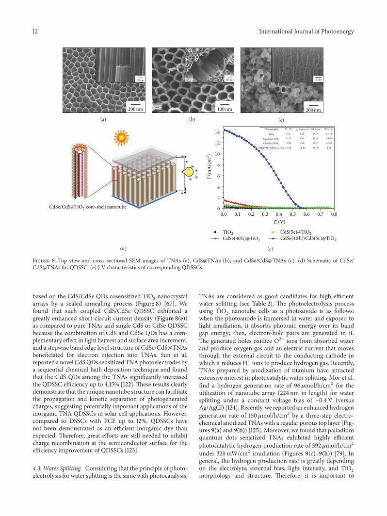
Figure 8: Top view and cross-sectional SEM images of TNAs (a), CdS@TNAs (b), and CdSe/CdS@TNAs (c). (d) Schematic of CdSe/CdS@TNAs for QDSSC. (e) J-V characteristics of corresponding QDSSCs.
based on the CdS/CdSe QDs cosensitized TiO2nanocrystal
arrays by a sealed annealing process (Figure 8) [67]. Wefound that such coupled CdS/CdSe QDSSC exhibited agreatly enhanced short-circuit current density (Figure 8(e))as compared to pure TNAs and single CdS or CdSe QDSSCbecause the combination of CdS and CdSe QDs has a com-plementary effect in light harvest and surface area increment,and a stepwise band edge level structure of CdSe/CdS@TNAsbeneficiated for electron injection into TNAs. Sun et al.reported a novel CdSQDs sensitizedTNAphotoelectrodes bya sequential chemical bath deposition technique and foundthat the CdS QDs among the TNAs significantly increasedthe QDSSC efficiency up to 4.15% [122]. These results clearlydemonstrate that the unique nanotube structure can facilitatethe propagation and kinetic separation of photogeneratedcharges, suggesting potentially important applications of theinorganic TNA QDSSCs in solar cell applications. However,compared to DSSCs with PCE up to 12%, QDSSCs havenot been demonstrated as an efficient inorganic dye thanexpected. Therefore, great efforts are still needed to inhibitcharge recombination at the semiconductor surface for theefficiency improvement of QDSSCs [123].
4.3. Water Splitting. Considering that the principle of photo-electrolysis for water splitting is the samewith photocatalysis,
TNAs are considered as good candidates for high efficientwater splitting (see Table 2). The photoelectrolysis processusing TiO
2nanotube cells as a photoanode is as follows:
when the photoanode is immersed in water and exposed tolight irradiation, it absorbs photonic energy over its bandgap energy; then, electron-hole pairs are generated in it.The generated holes oxidize O2− ions from absorbed waterand produce oxygen gas and an electric current that movesthrough the external circuit to the conducting cathode inwhich it reduces H+ ions to produce hydrogen gas. Recently,TNAs prepared by anodization of titanium have attractedextensive interest in photocatalytic water splitting. Mor et al.find a hydrogen generation rate of 96𝜇mol/h/cm2 for theutilization of nanotube array (224 nm in length) for watersplitting under a constant voltage bias of −0.4V (versusAg/AgCl) [124]. Recently, we reported an enhanced hydrogengeneration rate of 150𝜇mol/h/cm2 by a three-step electro-chemical anodizedTNAswith a regular porous top layer (Fig-ures 9(a) and 9(b)) [125]. Moreover, we found that palladiumquantum dots sensitized TNAs exhibited highly efficientphotocatalytic hydrogen production rate of 592 𝜇mol/h/cm2under 320mW/cm2 irradiation (Figures 9(c)–9(h)) [79]. Ingeneral, the hydrogen production rate is greatly dependingon the electrolyte, external bias, light intensity, and TiO
2
morphology and structure. Therefore, it is important to

International Journal of Photoenergy 13
Table 2: Summary of TNAs based materials in water splitting.
Photoanode Light intensity(mW/cm2) Electrolyte Photocurrent
(mA/cm2)Water splitting(𝜇mol/h/cm2)
Reference
C-TNAs N/A; 500W Xe lamp 0.1MNa2S +0.02MNa2SO3
N/A 1.6(0.040mL/h/cm2)
[126]
TNAs 70; 300W Xe lamp 1MKOH [email protected] versusNHE
7.1(0.178mL/h/cm2)
[127]
C-TNAs (C-containing TiO2based nanotube arrays) 12.7, 300W Xe Lamp 1MKOH 1.96@0V versus
Ag/AgCl11.28
(0.282mL/h/cm2)[128]
TNAs with etchingpretreatment
87, 300WAM 1.5 1MKOH [email protected] RHE 34.8
(0.87mL/h/cm2)[129]
Ru/[email protected] at% Ru 100 1MKOH [email protected] versusAg/AgCl 45 (1.08mL/h/cm2) [130]
TNAs (224 nm length, 34 nmwall thickness) 100 1MKOH 13.0@0V versus
Ag/AgCl96
(2.30mL/h/cm2)[124]
TNAs 110 1MKOH +0.5MH2SO4
4.95 97 (2.32mL/h/cm2) [131]
TNAs 74 1MKOH N/A 140(3.28mL/h/cm2)
[132]
Leaf-like TiO2/TNAs 320 2MNa2CO3 +0.5MEG
[email protected] versusSCE 150 [125]
Pyrococcus furiosus/TNAs 74 1MKOH N/A 234.88 [133]
TNAs 74 1MKOH [email protected] V versusAg/AgCl 250 [134]
TNAs (three-stepanodization) 320 2MNa2CO3 +
0.5MEG24@−0.3 V versus
SCE 420 [135]
Pt@TNAs 320 2MNa2CO3 +0.5MEG
24.2@−0.3 V versusSCE 495 [80]
Pd@TNAs 320 2MNa2CO3 +0.5MEG
[email protected] versusSCE 592 [79]
optimize these parameters and fundamentally understandtheir possible correlations to clarify the approaches towardto construct high efficient cell for hydrogen generation.
4.4. Other Applications. Asmentioned above, another specialelectrochemical feature of TNAs or some other TiO
2nan-
otube based materials is its ability to serve as a host for smallions insertion, typically hydrogen ion or lithium ion, into thelattice, leading to the drastic change of electronic and opticalproperties for potential applications in lithium-battery [4,136, 137], electrochromic devices [138, 139], and supercapaci-tor [140, 141].The kinetics, magnitude, and reversibility of theion insertion and electrochromic reaction strongly dependon the ion diffusion length and therefore on geometry of theelectrode surface. Due to the specific vertical alignment of theTNAs, a very high contrast can be obtained using verticallyoriented nanotubes. By deposition of Ag nanoparticles onthe TNAs, a material can be created that shows considerablephotochromic contrast [142]. Furthermore, the TNA has alsobeen proved to be good support for Pt or Pt/Ru catalysts forenhanced methanol electrooxidation [143, 144].
Other applications of the TNAs for biomedical implantare wetting template, target hydrogen sensing, electrochem-ical detection, and photogenerated cathode anticorrosion
[145–147]. For instance, the combination of organic modi-fication with a controllable photocatalytic reaction of TiO
2
was used to create microscale patterning surfaces with anydesired wettability value. Wetting micropatterns with differ-ent physical or chemical properties have frequently acted astemplates for fabricating various functional materials in alarge scale [148]. Moreover, wetting patterns with tailoredand reversible adhesion for microfluidic devices and micro-droplet manipulation have also been reported [149]. Forexample, Ag@TNA micropatterns show not only the high-throughput molecular sensing feature with high sensitive,reproducible performance but also show promising targetedantibacterials properties [148]. For gas sensing, Varghese et al.have shown instant resistance response in order of severalmagnitudes for the TNA layer upon exposure to 1000 ppmH
2
containing nitrogen atmospheres at room temperature [145].The applications of TNAs can significantly be expanded
if secondary material can successfully be deposited into thetubes. The TNAs can also be converted to other titanatesMTiO
3(M = Sr, Pd, Zr) with specific bioactive, piezoelectric
or ferroelectric properties and keep with its original tubestructure by a simple hydrothermal process in the corre-sponding precursor solution or a direct anodizing process inappropriate alloy substrates [150–153].

14 International Journal of Photoenergy
(a) (b) (c)
(d) (e) (f)
+ −
RE
O2 H2
H2
PlatinumTiO2 nanotube arrays
300 W Xe lamp
h−
H2O
H2O
O2
O
e−
Potentiostat
(g)
Pd
PdTiO2
Ti
TiO2
H2O
O2
Electrolyte
Pd QDs@TiO2 nanotubes
h�CB
VB
e−
h+
e−e−
h+
Ef
(h)
Figure 9: Top and cross-sectional SEM images of pure TNAs ((a), (b)) and Pd QDs@TNAs ((c), (d)). The insets show the correspondingmagnified images. TEM images of TNAs coated with Pd QDs. (g) Schematic of TNAs on photoelectrolytic water splitting for hydrogenproduction. (h) Schematic illustration of TNAs deposited with Pd QDs and the charge transfer process from TiO
2to Pd (lower right panel).
5. Conclusion
Till now, a large number of fundamental studies and appli-cation-oriented researches and developments are extensivelycarried out by many researchers for this low-dimensionalnanomaterial due to the expected various properties of TiO
2
(high surface area and controllable nanotube dimensions,geometries, and surface chemistry). This work has presentedthe recent progress of preparation and modification on theelectrochemically anodized TNA materials. These uniquelow dimensional nanostructure materials have been shownto have many favourable properties for potential appli-cations, including pollutant photocatalytic decomposition,
photovoltaic cells, biomedical scaffold, and wetting template.On the other hand, extensive challenges to fabricate highquality TNAs and develop various oxide nanotubes have beencontinued. For instance, rapid and high-efficient synthesis ofanatase TNAs and other multicomponent nanotubes underambient low-temperature conditions have recently beenreported [154]. Some other aspects aim to encompass the newprogress of TiO
2for an efficient utilization in photocatalytic
or photovoltaic applications under visible light, emphasizethe future trends of TiO
2in the environment and/or energy
related fields, and suggest new research directions, includingpreparation aspects for the development of this promisingmaterial [155].

International Journal of Photoenergy 15
Acknowledgments
Theauthors thank theAlexander vonHumboldt (AvH) Foun-dation of Germany, the EUMicrocare project (FP7-PEOPLE-2009-IRSES/247641), and the Natural Science Foundation ofJiangsu Province of China (Grant no. BK20130313) for thefinancial support of this work. We also acknowledge supportfrom the Priority Academic ProgramDevelopment of JiangsuHigher Education Institutions (PAPD).
References
[1] S. Iijima, “Helicalmicrotubules of graphitic carbon,”Nature, vol.354, no. 6348, pp. 56–58, 1991.
[2] J. C. Hulteen and C. R. Martin, “A general template-basedmethod for the preparation of nanomaterials,” Journal of Mate-rials Chemistry, vol. 7, no. 7, pp. 1075–1087, 1997.
[3] M. S. Sander, M. J. Cote, W. Gu, B. M. Kile, and C. P. Tripp,“Template-assisted fabrication of dense, aligned arrays of tita-nia nanotubes with well-controlled dimensions on substrates,”Advanced Materials, vol. 16, no. 22, pp. 2052–2057, 2004.
[4] D. V. Bavykin, J. M. Friedrich, and F. C. Walsh, “Protonatedtitanates and TiO
2nanostructured materials: synthesis, prop-
erties, and applications,” Advanced Materials, vol. 18, no. 21, pp.2807–2824, 2006.
[5] X. M. Sun and Y. D. Li, “Synthesis and characterization of ion-exchangeable titanate nanotubes,” Chemistry A: European Jour-nal, vol. 9, no. 10, pp. 2229–2238, 2003.
[6] T. Kasuga, M. Hiramatsu, A. Hoson, T. Sekino, and K. Niihara,“Formation of titanium oxide nanotube,” Langmuir, vol. 14, no.12, pp. 3160–3163, 1998.
[7] G. K. Mor, O. K. Varghese, M. Paulose, K. Shankar, and C. A.Grimes, “A review on highly ordered, vertically oriented TiO
2
nanotube arrays: fabrication, material properties, and solarenergy applications,” Solar EnergyMaterials and Solar Cells, vol.90, no. 14, pp. 2011–2075, 2006.
[8] J. M. Macak, H. Tsuchiya, A. Ghicov et al., “TiO2nanotubes:
self-organized electrochemical formation, properties and appli-cations,” Current Opinion in Solid State and Materials Science,vol. 11, no. 1-2, pp. 3–18, 2007.
[9] C. A. Grimes, “Synthesis and application of highly orderedarrays of TiO
2nanotubes,” Journal of Materials Chemistry, vol.
17, no. 15, pp. 1451–1457, 2007.[10] P. Roy, S. Berger, and P. Schmuki, “TiO
2nanotubes: synthesis
and applications,” Angewandte Chemie—International Edition,vol. 50, no. 13, pp. 2904–2939, 2011.
[11] Z. R. Tian, J. A. Voigt, J. Liu, B. McKenzie, and H. Xu, “Largeoriented arrays and continuous films of TiO
2-based nanotubes,”
Journal of the American Chemical Society, vol. 125, no. 41, pp.12384–12385, 2003.
[12] V. Zwilling, E. Darque-Ceretti, A. Boutry-Forveille, D. David,M. Y. Perrin, andM. Aucouturier, “Structure and physicochem-istry of anodic oxide films on titanium and TA6V alloy,” Surfaceand Interface Analysis, vol. 27, no. 7, pp. 629–637, 1999.
[13] D. Gong, C. A. Grimes, O. K. Varghese et al., “Titanium oxidenanotube arrays prepared by anodic oxidation,” Journal ofMaterials Research, vol. 16, no. 12, pp. 3331–3334, 2001.
[14] R. Beranek, H. Hildebrand, and P. Schmuki, “Self-organizedporous titanium oxide prepared in H
2SO4/HF electrolytes,”
Electrochemical and Solid-State Letters, vol. 6, no. 3, pp. B12–B14,2003.
[15] Y.-K. Lai, L. Sun, J. Zuo, and C.-J. Lin, “Electrochemical fabri-cation and formation mechanism of TiO
2nanotube arrays on
metallic titanium surface,” Acta Physico Chimica Sinica, vol. 20,no. 9, pp. 1063–1066, 2004.
[16] J. M. Macak, H. Tsuchiya, and P. Schmuki, “High-aspect-ratio TiO
2nanotubes by anodization of titanium,” Angewandte
Chemie—International Edition, vol. 44, no. 14, pp. 2100–2102,2005.
[17] J. M. Macak, H. Tsuchiya, L. Taveira, S. Aldabergerova, andP. Schmuki, “Smooth anodic TiO
2nanotubes,” Angewandte
Chemie—International Edition, vol. 44, no. 45, pp. 7463–7465,2005.
[18] G. K. Mor, O. K. Varghese, M. Paulose, N. Mukherjee, andC. A. Grimes, “Fabrication of tapered, conical-shaped titaniananotubes,” Journal of Materials Research, vol. 18, no. 11, pp.2588–2593, 2003.
[19] G. K. Mor, O. K. Varghese, M. Paulose, and C. A. Grimes,“Transparent highly ordered TiO
2nanotube arrays via anodiza-
tion of titanium thin films,”Advanced Functional Materials, vol.15, no. 8, pp. 1291–1296, 2005.
[20] G. K. Mor, K. Shankar, M. Paulose, O. K. Varghese, and C. A.Grimes, “Use of highly-ordered TiO
2nanotube arrays in dye-
sensitized solar cells,” Nano Letters, vol. 6, no. 2, pp. 215–218,2006.
[21] S. P. Albu, A. Ghicov, J. M. Macak, R. Hahn, and P. Schmuki,“Self-organized, free-standing TiO
2nanotube membrane for
flow-through photocatalytic applications,” Nano Letters, vol. 7,no. 5, pp. 1286–1289, 2007.
[22] M. Paulose, H. E. Prakasam, O. K. Varghese et al., “TiO2
nanotube arrays of 1000 𝜇m length by anodization of titaniumfoil: phenol red diffusion,” Journal of Physical Chemistry C, vol.111, no. 41, pp. 14992–14997, 2007.
[23] J. M. Macak, S. P. Albu, and P. Schmuki, “Towards ideal hexa-gonal self-ordering of TiO
2nanotubes,” Physica Status Solidi,
vol. 1, no. 5, pp. 181–183, 2007.[24] G. Zhang, H. Huang, Y. Zhang, H. L. W. Chan, and L.
Zhou, “Highly ordered nanoporous TiO2and its photocatalytic
properties,” Electrochemistry Communications, vol. 9, no. 12, pp.2854–2858, 2007.
[25] J. H. Ni, K. Noh, C. J. Frandsen et al., “Preparation of nearmicrometer-sized TiO
2nanotube arrays by high voltage anodi-
zation,”Materials Science&EngineeringC, vol. 33, no. 1, pp. 259–264, 2013.
[26] S. P. Albu and P. Schmuki, “TiO2nanotubes grown in differ-
ent organic electrolytes: two-size self-organization, single vs.double-walled tubes, and giant diameters,” Physica Status Solidi,vol. 4, no. 8-9, pp. 215–217, 2010.
[27] A. El Ruby Mohamed and S. Rohani, “Modified TiO2nanotube
arrays (TNTAs): progressive strategies towards visible lightresponsive photoanode, a review,” Energy & EnvironmentalScience, vol. 4, no. 4, pp. 1065–1086, 2011.
[28] J. M. MacAk, K. Sirotna, and P. Schmuki, “Self-organizedporous titanium oxide prepared in Na
2SO4/NaF electrolytes,”
Electrochimica Acta, vol. 50, no. 18, pp. 3679–3684, 2005.[29] Q.Cai,M. Paulose,O.K.Varghese, andC.A.Grimes, “The effect
of electrolyte composition on the fabrication of self-organizedtitanium oxide nanotube arrays by anodic oxidation,” Journal ofMaterials Research, vol. 20, no. 1, pp. 230–236, 2005.
[30] R. Hahn, J. M. Macak, and P. Schmuki, “Rapid anodic growthof TiO
2and WO
3nanotubes in fluoride free electrolytes,”
Electrochemistry Communications, vol. 9, no. 5, pp. 947–952,2007.

16 International Journal of Photoenergy
[31] K.-I. Ishibashi, R.-T. Yamaguchi, Y. Kimura, and M. Niwano,“Fabrication of titaniumoxide nanotubes by rapid and homoge-neous anodization in perchloric acid/ethanol mixture,” Journalof the Electrochemical Society, vol. 155, no. 1, pp. K10–K14, 2008.
[32] S. Bauer, S. Kleber, and P. Schmuki, “TiO2nanotubes: tailoring
the geometry inH3PO4/HF electrolytes,”Electrochemistry Com-
munications, vol. 8, no. 8, pp. 1321–1325, 2006.[33] L. V. Taveira, J. M. Macak, H. Tsuchiya, L. F. P. Dick, and P.
Schmuki, “Initiation and growth of self-organized TiO2nan-
otubes anodically formed in NH4F/(NH
4)2SO4electrolytes,”
Journal of the Electrochemical Society, vol. 152, no. 10, pp. B405–B410, 2005.
[34] Y. Lai, X. Gao, H. Zhuang, J. Huang, C. Lin, and L. Jiang,“Designing superhydrophobic porous nanostructures with tun-able water adhesion,” Advanced Materials, vol. 21, no. 37, pp.3799–3803, 2009.
[35] H. Yin, H. Liu, and W. Z. Shen, “The large diameter and fastgrowth of self-organized TiO
2nanotube arrays achieved via
electrochemical anodization,” Nanotechnology, vol. 21, no. 3,Article ID 035601, 2010.
[36] S. P. Albu and P. Schmuki, “TiO2nanotubes grown in differ-
ent organic electrolytes: two-size self-organization, single vs.double-walled tubes, and giant diameters,” Physica Status Solidi,vol. 4, no. 8-9, pp. 215–217, 2010.
[37] S. P. Albu, P. Roy, S. Virtanen, and P. Schmuki, “Self-organizedTiO2nanotube arrays: critical effects on morphology and
growth,” Israel Journal of Chemistry, vol. 50, no. 4, pp. 453–467,2010.
[38] Y. Wang, Y. Wu, Y. Qin et al., “Rapid anodic oxidation ofhighly ordered TiO
2nanotube arrays,” Journal of Alloys and
Compounds, vol. 509, no. 14, pp. L157–L160, 2011.[39] A. Ghicov and P. Schmuki, “Self-ordering electrochemistry: a
review on growth and functionality of TiO2nanotubes and
other self-aligned MOx structures,” Chemical Communications,no. 20, pp. 2791–2808, 2009.
[40] C. W. Lai and S. Sreekantan, “Photoelectrochemical perfor-mance of smooth TiO
2nanotube arrays: effect of anodization
temperature and cleaning methods,” International Journal ofPhotoenergy, vol. 2012, Article ID 356943, 11 pages, 2012.
[41] Y.-C. Lim, Z. Zainal,W.-T. Tan, andM.Z.Hussein, “Anodizationparameters influencing the growth of titania nanotubes andtheir photoelectrochemical response,” International Journal ofPhotoenergy, vol. 2012, Article ID 638017, 2012.
[42] J. Wang and Z. Q. Lin, “Anodic formation of ordered TiO2nan-
otube arrays: effects of electrolyte temperature and anodizationpotential,” Journal of Physical Chemistry C, vol. 113, no. 10, pp.4026–4030, 2009.
[43] Y. Lai, H. Zhuang, L. Sun, Z. Chen, and C. Lin, “Self-organizedTiO2nanotubes in mixed organic-inorganic electrolytes and
their photoelectrochemical performance,” Electrochimica Acta,vol. 54, no. 26, pp. 6536–6542, 2009.
[44] Y.-Y. Song and P. Schmuki, “Modulated TiO2nanotube stacks
and their use in interference sensors,” Electrochemistry Commu-nications, vol. 12, no. 4, pp. 579–582, 2010.
[45] R. Asahi, T. Morikawa, T. Ohwaki, K. Aoki, and Y. Taga,“Visible-light photocatalysis in nitrogen-doped titaniumoxides,” Science, vol. 293, no. 5528, pp. 269–271, 2001.
[46] J. H. Park, S. Kim, and A. J. Bard, “Novel carbon-doped TiO2
nanotube arrays with high aspect ratios for efficient solar watersplitting,” Nano Letters, vol. 6, no. 1, pp. 24–28, 2006.
[47] D. Li, H. Haneda, N. K. Labhsetwar, S. Hishita, and N. Ohashi,“Visible-light-driven photocatalysis on fluorine-doped TiO
2
powders by the creation of surface oxygen vacancies,” ChemicalPhysics Letters, vol. 401, no. 4-6, pp. 579–584, 2005.
[48] T. Umebayashi, T. Yamaki, H. Itoh, and K. Asai, “Band gapnarrowing of titanium dioxide by sulfur doping,” AppliedPhysics Letters, vol. 81, no. 3, pp. 454–456, 2002.
[49] N. Lu, X. Quan, J. Li, S. Chen, H. Yu, and G. Chen, “Fabricationof boron-doped TiO
2nanotube array electrode and investiga-
tion of its photoelectrochemical capability,” Journal of PhysicalChemistry C, vol. 111, no. 32, pp. 11836–11842, 2007.
[50] P. Zhou, J. G. Yu, and Y. X. Wang, “The new understand-ing on photocatalytic mechanism of visible-lightresponse N-Scodoped anatase TiO
2by first-principles,” Applied Catalysis B,
vol. 142-143, pp. 45–53, 2013.[51] J. G. Yu, P. Zhou, and Q. Li, “New insight into the enhanced
visible-light photocatalytic activities of B-, C- and B/C-dopedanatase TiO
2by first-principles,” Physical Chemistry Chemical
Physics, vol. 15, no. 29, pp. 12040–12047, 2013.[52] R. P. Antony, T. Mathews, K. Panda, B. Sundaravel, S. Dash,
and A. K. Tyagi, “Enhanced field emission properties of elec-trochemically synthesized self-aligned nitrogen-doped TiO
2
nanotube array thin films,” Journal of Physical Chemistry C, vol.116, no. 31, pp. 16740–16746, 2012.
[53] H.-Y. Wang, X.-J. Xu, J.-H. Wei, R. Xiong, and J. Shi, “Structureand raman investigations of nitrogen-doped TiO
2nanotube
arrays,” Solid State Phenomena, vol. 181-182, pp. 422–425, 2012.[54] S. P. Li, S. W. Lin, J. J. Liao, N. Q. Pan, D. H. Li, and J. B. Li,
“Nitrogen-doped TiO2nanotube arrays with enhanced photo-
electrochemical property,” International Journal of Photoenergy,vol. 2012, Article ID 794207, 7 pages, 2012.
[55] Y.-K. Lai, J.-Y. Huang, H.-F. Zhang et al., “Nitrogen-doped TiO2
nanotube array films with enhanced photocatalytic activityunder various light sources,” Journal of Hazardous Materials,vol. 184, no. 1–3, pp. 855–863, 2010.
[56] Q. Xue, Y. J. Guan, Z. B. Wang, and S. L. Bai, “Preparationof nitrogen doped TiO
2nanotube arrays and its visible light
responsive photocatalytic properties,” Acta Chimica Sinica, vol.68, no. 16, pp. 1603–1608, 2010.
[57] G. Liu, F. Li, D.-W. Wang et al., “Electron field emission of anitrogen-doped TiO
2nanotube array,” Nanotechnology, vol. 19,
no. 2, Article ID 025606, 2008.[58] D. Kim, H. Tsuchiya, S. Fujimoto, F. Schmidt-Stein, and P.
Schmuki, “Nitrogen-doped TiO2mesosponge layers formed by
anodization of nitrogen-containing Ti alloys,” Journal of SolidState Electrochemistry, vol. 16, no. 1, pp. 89–92, 2012.
[59] D. Kim, S. Fujimoto, P. Schmuki, and H. Tsuchiya, “Nitrogendoped anodic TiO
2nanotubes grown fromnitrogen-containing
Ti alloys,” Electrochemistry Communications, vol. 10, no. 6, pp.910–913, 2008.
[60] A. Ghicov, J. M. Macak, H. Tsuchiya et al., “TiO2nanotube
layers: dose effects during nitrogen doping by ion implantation,”Chemical Physics Letters, vol. 419, no. 4–6, pp. 426–429, 2006.
[61] A.Ghicov, J.M.Macak,H. Tsuchiya et al., “Ion implantation andannealing for an efficient N-doping of TiO
2nanotubes,” Nano
Letters, vol. 6, no. 5, pp. 1080–1082, 2006.[62] R. P. Vitiello, J. M. Macak, A. Ghicov, H. Tsuchiya, L. F. P. Dick,
and P. Schmuki, “N-Doping of anodic TiO2nanotubes using
heat treatment in ammonia,” Electrochemistry Communications,vol. 8, no. 4, pp. 544–548, 2006.

International Journal of Photoenergy 17
[63] R. Hahn, A. Ghicov, J. Salonen, V.-P. Lehto, and P. Schmuki,“Carbon doping of self-organized TiO
2nanotube layers by
thermal acetylene treatment,” Nanotechnology, vol. 18, no. 10,Article ID 105604, 2007.
[64] Y.-F. Tu, S.-Y. Huang, J.-P. Sang, and X.-W. Zou, “Preparationof Fe-doped TiO
2nanotube arrays and their photocatalytic
activities under visible light,” Materials Research Bulletin, vol.45, no. 2, pp. 224–229, 2010.
[65] A. Ghicov, B. Schmidt, J. Kunze, and P. Schmuki, “Photore-sponse in the visible range from Cr doped TiO
2nanotubes,”
Chemical Physics Letters, vol. 433, no. 4–6, pp. 323–326, 2007.[66] Z. Xu and J. Yu, “Visible-light-induced photoelectrochemical
behaviors of Fe-modifiedTiO2nanotube arrays,”Nanoscale, vol.
3, no. 8, pp. 3138–3144, 2011.[67] Y. K. Lai, Z. Q. Lin, D. J. Zheng, L. F. Chi, R. G. Du, and C. J. Lin,
“CdSe/CdS quantum dots co-sensitized TiO2nanotube array
photoelectrode for highly efficient solar cells,” ElectrochimicaActa, vol. 79, pp. 175–181, 2012.
[68] G. S. Li, L. Wu, F. Li, P. P. Xu, D. Q. Zhang, and H. X. Li,“Photoelectrocatalytic degradation of organic pollutants via aCdS quantum dots enhanced TiO
2nanotube array electrode
under visible light irradiation,”Nanoscale, vol. 5, no. 5, pp. 2118–2125, 2013.
[69] D. H. Li, N. Q. Pan, J. J. Liao, X. K. Cao, and S. W. Lin,“Effects of surface modification of TiO
2nanotube arrays on
the performance of CdS quantum-dot-sensitized solar cells,”International Journal of Photoenergy, vol. 2013, Article ID129621, 10 pages, 2013.
[70] Z.-Q. Lin, Y.-K. Lai, R.-G. Hu, J. Li, R.-G. Du, and C.-J.Lin, “A highly efficient ZnS/CdS@TiO
2photoelectrode for
photogenerated cathodic protection of metals,” ElectrochimicaActa, vol. 55, no. 28, pp. 8717–8723, 2010.
[71] J. M. Macak, B. G. Gong, M. Hueppe, and P. Schmuki, “Fill-ing of TiO
2nanotubes by self-doping and electrodeposition,”
Advanced Materials, vol. 19, no. 19, pp. 3027–3031, 2007.[72] C. W. Lai and S. Sreekantan, “Preparation of hybrid WO
3-
TiO2nanotube photoelectrodes using anodization and wet
impregnation: improved water-splitting hydrogen generationperformance,” International Journal of Hydrogen Energy, vol. 38,no. 5, pp. 2156–2166, 2013.
[73] C.W. Lai and S. Sreekantan, “Incorporation ofWO3species into
TiO2nanotubes via wet impregnation and their water-splitting
performance,” Electrochimica Acta, vol. 87, pp. 294–302, 2013.[74] Y. Hou, X. Li, X. Zou, X. Quan, and G. Chen, “Photoeletrocat-
alytic activity of a Cu2O-loaded self-organized highly oriented
TiO2nanotube array electrode for 4-chlorophenol degrada-
tion,” Environmental Science & Technology, vol. 43, no. 3, pp.858–863, 2009.
[75] G. Dai, J. Yu, and G. Liu, “Synthesis and enhanced visible-light photoelectrocatalytic activity of P-N junction BiOI/TiO
2
nanotube arrays,” Journal of Physical Chemistry C, vol. 115, no.15, pp. 7339–7346, 2011.
[76] M. Y. Wang, L. Sun, Z. Q. Lin, J. H. Cai, K. P. Xie, and C. J.Lin, “p-n Heterojunction photoelectrodes composed of Cu
2O-
loaded TiO2nanotube arrays with enhanced photoelectro-
chemical and photoelectrocatalytic activities,” Energy & Envi-ronmental Science, vol. 6, no. 4, pp. 1211–1220, 2013.
[77] M. Ye, X. Xin, C. Lin, and Z. Lin, “High efficiency dye-sensitizedsolar cells based on hierarchically structured nanotubes,” NanoLetters, vol. 11, no. 8, pp. 3214–3220, 2011.
[78] I. Paramasivam, J. M. Macak, and P. Schmuki, “Photocatalyticactivity of TiO
2nanotube layers loaded with Ag and Au
nanoparticles,” Electrochemistry Communications, vol. 10, no. 1,pp. 71–75, 2008.
[79] M. D. Ye, J. J. Gong, Y. K. Lai, C. J. Lin, and Z. Q. Lin, “High-efficiency photoelectrocatalytic hydrogen generation enabledby palladium quantum dots-sensitized TiO
2nanotube arrays,”
Journal of the American Chemical Society, vol. 134, no. 38, pp.15720–15723, 2012.
[80] Y. Lai, J. Gong, and C. Lin, “Self-organized TiO2nanotube
arrays with uniform platinum nanoparticles for highly efficientwater splitting,” International Journal of Hydrogen Energy, vol.37, no. 8, pp. 6438–6446, 2012.
[81] L. Yang, D. He, Q. Cai, and C. A. Grimes, “Fabrication andcatalytic properties of Co-Ag-Pt nanoparticle-decorated titaniananotube arrays,” Journal of Physical Chemistry C, vol. 111, no.23, pp. 8214–8217, 2007.
[82] P. F. Fu, P. Y. Zhang, and J. Li, “Simultaneous elimination offormaldehyde and ozone byproduct using noblemetalmodifiedTiO2films in the gaseous VUV photocatalysis,” International
Journal of Photoenergy, vol. 2012, Article ID 174862, 8 pages,2012.
[83] Y. Tang, P. Wee, Y. Lai et al., “Hierarchical TiO2nanoflakes
and nanoparticles hybrid structure for improved photocatalyticactivity,” Journal of Physical Chemistry C, vol. 116, no. 4, pp.2772–2780, 2012.
[84] Z. Xu, J. Yu, and G. Liu, “Enhancement of ethanol electrooxida-tion on plasmonic Au/TiO
2nanotube arrays,” Electrochemistry
Communications, vol. 13, no. 11, pp. 1260–1263, 2011.[85] J. Yu, G. Dai, and B. Huang, “Fabrication and characterization
of visible-light-driven plasmonic photocatalyst Ag/AgCl/TiO2
nanotube arrays,” Journal of Physical Chemistry C, vol. 113, no.37, pp. 16394–16401, 2009.
[86] L. Sun, J. Li, C. Wang et al., “Ultrasound aided photochemicalsynthesis of Ag loaded TiO
2nanotube arrays to enhance
photocatalytic activity,” Journal of HazardousMaterials, vol. 171,no. 1–3, pp. 1045–1050, 2009.
[87] Y. Lai, H. Zhuang, K. Xie et al., “Fabrication of uniformAg/TiO2
nanotube array structures with enhanced photoelectrochemicalperformance,”New Journal of Chemistry, vol. 34, no. 7, pp. 1335–1340, 2010.
[88] C. Liu, Y. Teng, R. Liu et al., “Fabrication of graphene films onTiO2nanotube arrays for photocatalytic application,” Carbon,
vol. 49, no. 15, pp. 5312–5320, 2011.[89] P. Wang, J. Wang, X. F. Wang et al., “One-step synthesis of
easy-recycling TiO2-rGO nanocomposite photocatalysts with
enhanced photocatalytic activity,” Applied Catalysis B, vol. 132,pp. 452–459, 2013.
[90] Y. Hou, X. Li, Q. Zhao, G. Chen, and C. L. Raston, “Role ofhydroxyl radicals and mechanism of escherichia coli inactiva-tion on Ag/AgBr/TiO
2nanotube array electrode under visible
light irradiation,” Environmental Science & Technology, vol. 46,no. 7, pp. 4042–4050, 2012.
[91] A. Fujishima and K. Honda, “Electrochemical photolysis ofwater at a semiconductor electrode,” Nature, vol. 238, no. 5358,pp. 37–38, 1972.
[92] Y. Lai, L. Sun, Y. Chen, H. Zhuang, C. Lin, and J. W. Chin,“Effects of the structure of TiO
2nanotube array on Ti substrate
on its photocatalytic activity,” Journal of the ElectrochemicalSociety, vol. 153, no. 7, pp. D123–D127, 2006.
[93] H.-F. Zhuang, C.-J. Lin, Y.-K. Lai, L. Sun, and J. Li, “Somecritical structure factors of titanium oxide nanotube array inits photocatalytic activity,” Environmental Science & Technology,vol. 41, no. 13, pp. 4735–4740, 2007.

18 International Journal of Photoenergy
[94] I. Paramasivam, H. Jha, N. Liu, and P. Schmuki, “A Review ofphotocatalysis using self-organized TiO
2nanotubes and other
ordered oxide nanostructures,” Small, vol. 8, no. 20, pp. 3073–3103, 2012.
[95] K. Nakata and A. Fujishima, “TiO2photocatalysis: design and
applications,” Journal of Photochemistry and Photobiology C, vol.13, no. 3, pp. 169–189, 2012.
[96] J. Yu and B. Wang, “Effect of calcination temperature onmorphology and photoelectrochemical properties of anodizedtitanium dioxide nanotube arrays,” Applied Catalysis B, vol. 94,no. 3-4, pp. 295–302, 2010.
[97] J. M. Macak, M. Zlamal, J. Krysa, and P. Schmuki, “Self-organized TiO
2nanotube layers as highly efficient photocata-
lysts,” Small, vol. 3, no. 2, pp. 300–304, 2007.[98] Y. J. Xin, H. L. Liu, J. J. Li, Q. H. Chen, and D. Ma, “Influence of
post-treatment temperature of TNTa photoelectrodes on pho-toelectrochemical properties and photocatalytic degradation of4-nonylphenol,” Journal of Solid State Chemistry, vol. 199, pp.49–55, 2013.
[99] O. K. Varghese, D. Gong, M. Paulose, C. A. Grimes, and E.C. Dickey, “Crystallization and high-temperature structuralstability of titaniumoxide nanotube arrays,” Journal ofMaterialsResearch, vol. 18, no. 1, pp. 156–165, 2003.
[100] P. M. Hosseinpour, E. Panaitescu, D. Heiman, L. Menon, andL. H. Lewis, “Toward tailored functionality of titania nanotubearrays: interpretation of the magnetic-structural correlations,”Journal ofMaterials Research, vol. 28, no. 10, pp. 1304–1310, 2013.
[101] S. J. Liu, Q. Ma, F. Gao, S. H. Song, and S. Gao, “Relationshipbetween N-doping induced point defects by annealing inammonia and enhanced thermal stability for anodized titaniananotube arrays,” Journal of Alloys and Compounds, vol. 543, pp.71–78, 2012.
[102] Q. Wang, X. Yang, X. Wang, M. Huang, and J. Hou, “Synthesisof N-doped TiO
2mesosponge by solvothermal transformation
of anodic TiO2nanotubes and enhanced photoelectrochemical
performance,” Electrochimica Acta, vol. 62, pp. 158–162, 2012.[103] W. Krengvirat, S. Sreekantan, A. F. M. Noor et al., “Low-
temperature crystallization of TiO2nanotube arrays via hot
water treatment and their photocatalytic properties undervisible-light irradiation,” Materials Chemistry and Physics, vol.137, no. 3, pp. 991–998, 2013.
[104] J. Yu, G. Dai, and B. Cheng, “Effect of crystallization methodson morphology and photocatalytic activity of anodized TiO
2
nanotube array films,” Journal of Physical Chemistry C, vol. 114,no. 45, pp. 19378–19385, 2010.
[105] X. Lu, G. Wang, T. Zhai et al., “Hydrogenated TiO2nanotube
arrays for supercapacitors,”Nano Letters, vol. 12, no. 3, pp. 1690–1696, 2012.
[106] X. Zhang, Y. Ling, L. Liao, Z. Niu, S. Chen, and C. Zhao, “Effectof heat treatment on the photoelectrocatalytic performance ofTiO2nanotube array film,” Chinese Journal of Catalysis, vol. 31,
no. 10, pp. 1300–1304, 2010.[107] P. Xiao, D. Liu, B. B. Garcia, S. Sepehri, Y. Zhang, and G.
Cao, “Electrochemical and photoelectrical properties of titaniananotube arrays annealed in different gases,” Sensors andActuators B, vol. 134, no. 2, pp. 367–372, 2008.
[108] K. Xie, L. Sun, C. Wang et al., “Photoelectrocatalytic propertiesof Ag nanoparticles loaded TiO
2nanotube arrays prepared by
pulse current deposition,” Electrochimica Acta, vol. 55, no. 24,pp. 7211–7218, 2010.
[109] K. Xie, Q. Wu, Y. Wang et al., “Electrochemical construction ofZ-scheme type CdS-Ag-TiO
2nanotube arrays with enhanced
photocatalytic activity,” Electrochemistry Communications, vol.13, no. 12, pp. 1469–1472, 2011.
[110] B. O’Regan and M. Gratzel, “A low-cost, high-efficiency solarcell based on dye-sensitized colloidal TiO
2films,” Nature, vol.
353, no. 6346, pp. 737–740, 1991.[111] K. Zhu, N. R. Neale, A. Miedaner, and A. J. Frank, “Enhanced
charge-collection efficiencies and light scattering in dye-sensitized solar cells using oriented TiO
2nanotubes arrays,”
Nano Letters, vol. 7, no. 1, pp. 69–74, 2007.[112] M. Paulose, K. Shankar, O. K. Varghese, G. K. Mor, B. Hardin,
and C. A. Grimes, “Backside illuminated dye-sensitized solarcells based on titania nanotube array electrodes,” Nanotechnol-ogy, vol. 17, no. 5, pp. 1446–1448, 2006.
[113] K. Zhu, T. B. Vinzant, N. R. Neale, and A. J. Frank, “Removingstructural disorder from oriented TiO
2nanotube arrays: reduc-
ing the dimensionality of transport and recombination in dye-sensitized solar cells,”Nano Letters, vol. 7, no. 12, pp. 3739–3746,2007.
[114] J. Wang and Z. Q. Lin, “Dye-Sensitized TiO2Nanotube Solar
Cells: Rational Structural and Surface Engineering on TiO2
Nanotubes,” Chemistry: An Asian Journal, vol. 7, no. 12, pp.2754–2762, 2012.
[115] Z. Liu and M. Misra, “Bifacial dye-sensitized solar cells basedon vertically oriented TiO
2nanotube arrays,” Nanotechnology,
vol. 21, no. 12, Article ID 125703, 2010.[116] L. Sun, S. Zhang, X. Wang, X. W. Sun, D. Y. Ong, and A.
K. Ko Kyaw, “A novel parallel configuration of dye-sensitizedsolar cells with double-sided anodic nanotube arrays,” Energy& Environmental Science, vol. 4, no. 6, pp. 2240–2248, 2011.
[117] Q. Zheng,H. Kang, J. Yun, J. Lee, J. H. Park, and S. Baik, “Hierar-chical construction of self-standing anodized titania nanotubearrays and nanoparticles for efficient and cost-effective front-illuminated dye-sensitized solar cells,” ACS Nano, vol. 5, no. 6,pp. 5088–5093, 2011.
[118] A. Kongkanand, K. Tvrdy, K. Takechi,M.Kuno, and P.V. Kamat,“Quantum dot solar cells. Tuning photoresponse through sizeand shape control of CdSe-TiO
2architecture,” Journal of the
AmericanChemical Society, vol. 130, no. 12, pp. 4007–4015, 2008.[119] V. I. Klimov and D. W. McBranch, “Femtosecond 1P-to-
1S electron relaxation in strongly confined semiconductornanocrystals,” Physical Review Letters, vol. 80, no. 18, pp. 4028–4031, 1998.
[120] P. Sudhagar, J. H. Jung, S. Park et al., “The performance ofcoupled (CdS:CdSe) quantum dot-sensitized TiO
2nanofibrous
solar cells,” Electrochemistry Communications, vol. 11, no. 11, pp.2220–2224, 2009.
[121] Q. Shen, A. Yamada, S. Tamura, and T. Toyoda, “CdSe quantumdot-sensitized solar cell employing TiO
2nanotube working-
electrode and Cu2S counter-electrode,” Applied Physics Letters,
vol. 97, no. 12, Article ID 123107, 2010.[122] W.-T. Sun, A. Yu, H.-Y. Pan, X.-F. Gao, Q. Chen, and L.-
M. Peng, “CdS quantum dots sensitized TiO2nanotube-array
photoelectrodes,” Journal of the American Chemical Society, vol.130, no. 4, pp. 1124–1125, 2008.
[123] Z. Yang, C.-Y. Chen, P. Roy, and H.-T. Chang, “Quantum dot-sensitized solar cells incorporating nanomaterials,” ChemicalCommunications, vol. 47, no. 34, pp. 9561–9571, 2011.
[124] G. K. Mor, K. Shankar, M. Paulose, O. K. Varghese, and C.A. Grimes, “Enhanced photocleavage of water using titaniananotube arrays,” Nano Letters, vol. 5, no. 1, pp. 191–195, 2005.

International Journal of Photoenergy 19
[125] J. Gong, C. Lin, M. Ye, and Y. Lai, “Enhanced photoelectro-chemical activities of a nanocomposite filmwith a bamboo leaf-like structured TiO
2layer on TiO
2nanotube arrays,” Chemical
Communications, vol. 47, no. 9, pp. 2598–2600, 2011.[126] F. Jia, Z. Yao, Z. Jiang, and C. Li, “Preparation of carbon
coated TiO2nanotubes film and its catalytic application for H
2
generation,” Catalysis Communications, vol. 12, no. 6, pp. 497–501, 2011.
[127] Y. Li, H. Yu, W. Song, G. Li, B. Yi, and Z. Shao, “A novelphotoelectrochemical cell with self-organized TiO
2nanotubes
as photoanodes for hydrogen generation,” International Journalof Hydrogen Energy, vol. 36, no. 22, pp. 14374–14380, 2011.
[128] L. X. Sang, Z. Y. Zhang, G. M. Bai, C. X. Du, and C. F. Ma, “Aphotoelectrochemical investigation of the hydrogen-evolvingdoped TiO
2nanotube arrays electrode,” International Journal of
Hydrogen Energy, vol. 37, no. 1, pp. 854–859, 2012.[129] Y. R. Smith, B. Sarma, S. K.Mohanty, andM.Misra, “Single-step
anodization for synthesis of hierarchical TiO2nanotube arrays
on foil and wire substrate for enhanced photoelectrochemicalwater splitting,” International Journal of Hydrogen Energy, vol.38, no. 5, pp. 2062–2069, 2013.
[130] P. Roy, C. Das, K. Lee et al., “Oxide nanotubes on Ti-Ru alloys:strongly enhanced and stable photoelectrochemical activity forwater splitting,” Journal of the American Chemical Society, vol.133, no. 15, pp. 5629–5631, 2011.
[131] Y. Sun, G. Wang, and K. Yan, “TiO2nanotubes for hydro-
gen generation by photocatalytic water splitting in a two-compartment photoelectrochemical cell,” International Journalof Hydrogen Energy, vol. 36, no. 24, pp. 15502–15508, 2011.
[132] S. Bae, E. Shim, J. Yoon, and H. Joo, “Photoanodic and cathodicrole of anodized tubular titania in light-sensitized enzymatichydrogen production,” Journal of Power Sources, vol. 185, no. 1,pp. 439–444, 2008.
[133] J. Yoon, S. Bae, E. Shim, and H. Joo, “Pyrococcus furiosus-immobilized anodized tubular titania cathode in a hydrogenproduction system,” Journal of Power Sources, vol. 189, no. 2, pp.1296–1301, 2009.
[134] M. Park, A. Heo, E. Shim, J. Yoon, H. Kim, and H. Joo,“Effect of length of anodized TiO
2tubes on photoreactivity:
photocurrent, Cr(VI) reduction and H2evolution,” Journal of
Power Sources, vol. 195, no. 15, pp. 5144–5149, 2010.[135] J. Gong, Y. Lai, and C. Lin, “Electrochemically multi-anodized
TiO2nanotube arrays for enhancing hydrogen generation by
photoelectrocatalytic water splitting,” Electrochimica Acta, vol.55, no. 16, pp. 4776–4782, 2010.
[136] G. F. Ortiz, I. Hanzu, P. Knauth, P. Lavela, J. L. Tirado, and T.Djenizian, “TiO
2nanotubes manufactured by anodization of Ti
thin films for on-chip Li-ion 2Dmicrobatteries,” ElectrochimicaActa, vol. 54, no. 17, pp. 4262–4268, 2009.
[137] W.-H. Ryu, D.-H. Nam, Y.-S. Ko, R.-H. Kim, and H.-S. Kwon,“Electrochemical performance of a smooth and highly orderedTiO2nanotube electrode for Li-ion batteries,” Electrochimica
Acta, vol. 61, pp. 19–24, 2012.[138] A. Ghicov, S. P. Albu, J. M. Macak, and P. Schmuki, “High-
contrast electrochromic switching using transparent lift-offlayers of self-organized TiO
2nanotubes,” Small, vol. 4, no. 8, pp.
1063–1066, 2008.[139] A. Ghicov, M. Yamamoto, and P. Schmuki, “Lattice widening
in niobium-doped TiO2nanotubes: efficient ion intercala-
tion and swift electrochromic contrast,” Angewandte Chemie—International Edition, vol. 47, no. 41, pp. 7934–7937, 2008.
[140] J.-H. Kim, K. Zhu, Y. Yan, C. L. Perkins, and A. J. Frank,“Microstructure and pseudocapacitive properties of electrodesconstructed of oriented NiO-TiO
2nanotube arrays,” Nano
Letters, vol. 10, no. 10, pp. 4099–4104, 2010.[141] M. Salari, K. Konstantinov, and H. K. Liu, “Enhancement of the
capacitance in TiO2nanotubes through controlled introduction
of oxygen vacancies,” Journal of Materials Chemistry, vol. 21, no.13, pp. 5128–5133, 2011.
[142] I. Paramasivam, J. M. Macak, A. Ghicov, and P. Schmuki,“Enhanced photochromism of Ag loaded self-organized TiO
2
nanotube layers,” Chemical Physics Letters, vol. 445, no. 4–6, pp.233–237, 2007.
[143] J. M. Macak, P. J. Barczuk, H. Tsuchiya et al., “Self-organizednanotubular TiO
2matrix as support for dispersed Pt/Ru
nanoparticles: enhancement of the electrocatalytic oxidation ofmethanol,” Electrochemistry Communications, vol. 7, no. 12, pp.1417–1422, 2005.
[144] Y.-Y. Song, Z.-D. Gao, and P. Schmuki, “Highly uniform Ptnanoparticle decoration on TiO
2nanotube arrays: a refreshable
platform formethanol electrooxidation,” Electrochemistry Com-munications, vol. 13, no. 3, pp. 290–293, 2011.
[145] O. K. Varghese, D. Gong, M. Paulose, K. G. Ong, E. C. Dickey,and C. A. Grimes, “Extreme changes in the electrical resistanceof titania nanotubes with hydrogen exposure,” Advanced Mate-rials, vol. 15, no. 7-8, pp. 624–627, 2003.
[146] S. Mahshid, C. Li, S. S. Mahshid et al., “Sensitive determinationof dopamine in the presence of uric acid and ascorbic acid usingTiO2nanotubes modified with Pd, Pt and Au nanoparticles,”
Analyst, vol. 136, no. 11, pp. 2322–2329, 2011.[147] Z.-Q. Lin, Y.-K. Lai, R.-G. Hu, J. Li, R.-G. Du, and C.-J.
Lin, “A highly efficient ZnS/CdS@TiO2photoelectrode for
photogenerated cathodic protection of metals,” ElectrochimicaActa, vol. 55, no. 28, pp. 8717–8723, 2010.
[148] Y. K. Lai, L. X. Lin, F. Pan et al., “Bioinspired patterning withextreme wettability contrast on TiO
2nanotube array surface: a
versatile platform for biomedical applications,” Small, vol. 9, no.17, pp. 2945–2953, 2013.
[149] Y. K. Lai, F. Pan, C. Xu, H. Fuchs, and L. F. Chi, “In situsurface-modification-induced superhydrophobic patterns withreversible wettability and adhesion,” Advanced Materials, vol.25, no. 12, pp. 1682–1686, 2013.
[150] J. M. Macak, C. Zollfrank, B. J. Rodriguez et al., “Orderedferroelectric lead titanate nanocellular structure by conversionof anodic TiO
2nanotubes,” Advanced Materials, vol. 21, no. 30,
pp. 3121–3125, 2009.[151] Y. Xin, J. Jiang, K. Huo, T. Hu, and P. K. Chu, “Bioactive
SrTiO3nanotube arrays: strontium delivery platform on Ti-
based osteoporotic bone implants,” ACS Nano, vol. 3, no. 10, pp.3228–3234, 2009.
[152] K. Yasuda and P. Schmuki, “Formation of self-organized zirco-nium titanate nanotube layers by alloy anodization,” AdvancedMaterials, vol. 19, no. 13, pp. 1757–1760, 2007.
[153] Y. Yang, X. Wang, C. Zhong, C. Sun, and L. Li, “FerroelectricPbTiO
3nanotube arrays synthesized by hydrothermalmethod,”
Applied Physics Letters, vol. 92, no. 12, Article ID 122907, 2008.[154] J. Zhang, X. Tang, and D. Li, “One-step formation of crystalline
TiO2nanotubular arrays with intrinsic p-n junctions,” Journal
of Physical Chemistry C, vol. 115, no. 44, pp. 21529–21534, 2011.[155] R. Daghrir, P. Drogui, and D. Robert, “Modified TiO
2for
environmental photocatalytic applications: a review,” Industrial& Engineering Chemistry Research, vol. 52, no. 10, pp. 3581–3599,2013.

Submit your manuscripts athttp://www.hindawi.com
Hindawi Publishing Corporationhttp://www.hindawi.com Volume 2014
Inorganic ChemistryInternational Journal of
Hindawi Publishing Corporation http://www.hindawi.com Volume 2014
International Journal ofPhotoenergy
Hindawi Publishing Corporationhttp://www.hindawi.com Volume 2014
Carbohydrate Chemistry
International Journal of
Hindawi Publishing Corporationhttp://www.hindawi.com Volume 2014
Journal of
Chemistry
Hindawi Publishing Corporationhttp://www.hindawi.com Volume 2014
Advances in
Physical Chemistry
Hindawi Publishing Corporationhttp://www.hindawi.com
Analytical Methods in Chemistry
Journal of
Volume 2014
Bioinorganic Chemistry and ApplicationsHindawi Publishing Corporationhttp://www.hindawi.com Volume 2014
SpectroscopyInternational Journal of
Hindawi Publishing Corporationhttp://www.hindawi.com Volume 2014
The Scientific World JournalHindawi Publishing Corporation http://www.hindawi.com Volume 2014
Medicinal ChemistryInternational Journal of
Hindawi Publishing Corporationhttp://www.hindawi.com Volume 2014
Chromatography Research International
Hindawi Publishing Corporationhttp://www.hindawi.com Volume 2014
Applied ChemistryJournal of
Hindawi Publishing Corporationhttp://www.hindawi.com Volume 2014
Hindawi Publishing Corporationhttp://www.hindawi.com Volume 2014
Theoretical ChemistryJournal of
Hindawi Publishing Corporationhttp://www.hindawi.com Volume 2014
Journal of
Spectroscopy
Analytical ChemistryInternational Journal of
Hindawi Publishing Corporationhttp://www.hindawi.com Volume 2014
Journal of
Hindawi Publishing Corporationhttp://www.hindawi.com Volume 2014
Quantum Chemistry
Hindawi Publishing Corporationhttp://www.hindawi.com Volume 2014
Organic Chemistry International
ElectrochemistryInternational Journal of
Hindawi Publishing Corporation http://www.hindawi.com Volume 2014
Hindawi Publishing Corporationhttp://www.hindawi.com Volume 2014
CatalystsJournal of