review and guidelines for treating head and neck tumors...
TRANSCRIPT

AAPM 2010 1
Review and guidelines for treating head and neck tumors
using IMRT and VMAT
Debbie Schofield,Laurence Court,
Chuck Mayo

AAPM 2010 2
Educational Objectives:• Discuss the issues surrounding plan evaluation:
Variability in target definition, prescriptions, margins, etc.
• Discuss different approaches for the use of IMRT for treating head and neck tumors
• Describe the use of VMAT to treat head and neck tumors
• Comparison of VMAT and IMRT for head and neck tumors

AAPM 2010 3
Variability in planning criteria and plan evaluation
• Target / prescription variability• Contouring variability• Margins• Coverage / hotspots
Laurence Court, PhDDana-Farber / Brigham & Women’s Cancer Center,
Harvard Medical School,Boston MA
Current address: U.T. M.D. Anderson Cancer CenterHouston, TX

AAPM 2010 4
Acknowledgements
• Roy Tishler, DFCI• Indra Das, Indiana University • Martin Murphy, Virginia Commonwealth
University • Wolfgang Tomé, University of Wisconsin• Debbie Schofield, Baptist Cancer Institute• Chuck Mayo, Mayo Clinic
AAPM 2010 5
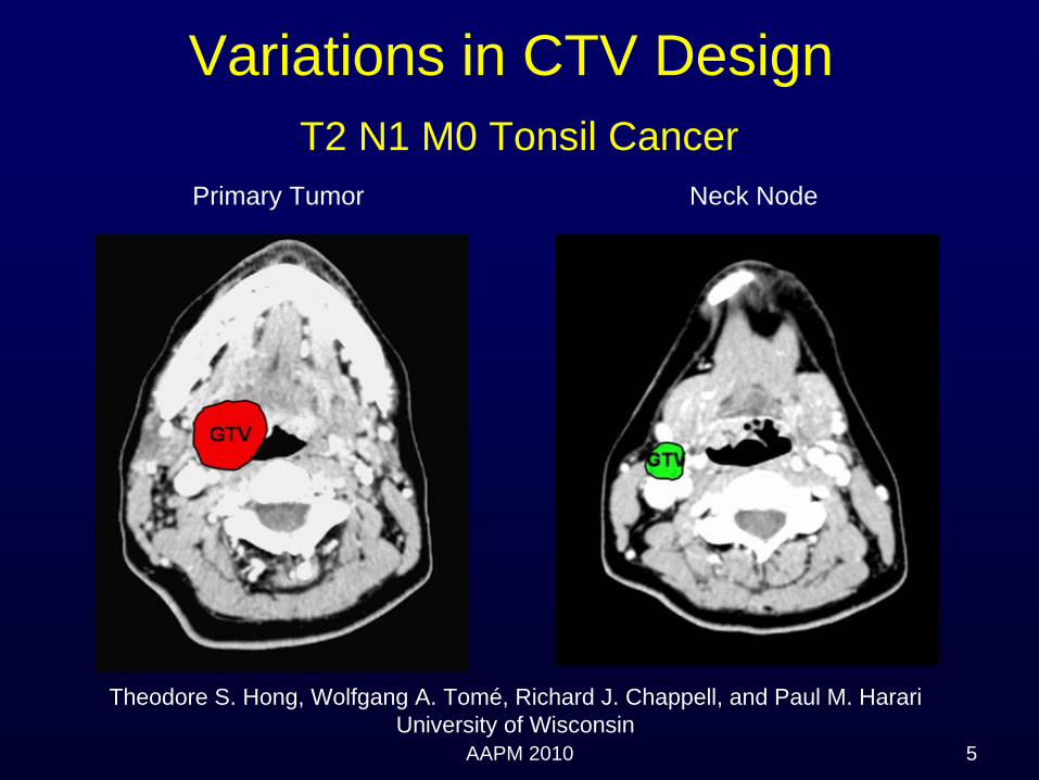
Variations in CTV Design T2 N1 M0 Tonsil Cancer
Theodore S. Hong, Wolfgang A. Tomé, Richard J. Chappell, and Paul M. HarariUniversity of Wisconsin
Primary Tumor Neck Node

AAPM 2010 6
Theodore S. Hong, Wolfgang A. Tomé, Richard J. Chappell, and Paul M. HarariUniversity of Wisconsin

AAPM 2010 7
Bilateral vs. Ipsilateral Elective CTV Design
Ipsilateral
15.8%
Bilateral
84.2%
Single level
36.8%Multiple levels
63.2%
TS Hong et. al.
AAPM 2010 8
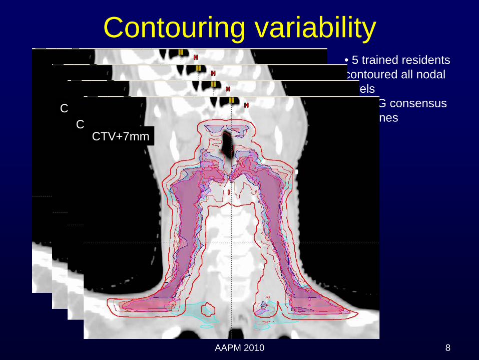
• 5 trained residents contoured all nodal levels• RTOG consensus guidelines
Contouring variability
CTV+3mmCTV+5mm
CTV+7mm

AAPM 2010 9
Effect of contouring on target dose
Data from Lu et al, VCU (Martin Murphy)PTV=CTV+ (3 - 5mm)

AAPM 2010 10
Effect of contouring on parotid dose
Data from Lu et al, VCU (Martin Murphy)

AAPM 2010 11
Margins• PTV expansions to account for setup
– Mean: 4.1 mm (Hong et al)– Range: 0-15 mm– UMass: 3-5mm, MDACC: 3-4, DFCI: 3-5mm, Mayo: 3mm– MD draws PTV
• Use of optimization structures• Pull back from skin (3-5mm)
– DFCI: 3mm (PTV), – UMass: 4mm (IMRT PTV)
• Planning Risk Volume: 0 – 10mm– Cord: 5mm (MDACC, MNCJAX), 7mm (DFCI), 1cm (UMass)
[3cm posterior]– Optic nerves: 3mm (DFCI and UMass)– Parotid: 0mm

AAPM 2010 12
Target coverage
• 100% PTV covered by 100% (Mayo)• 95% of PTV getting 100% prescription,
‘most’ covered by 98% isodose (DFCI)• 99%+ CTV covered by 100% (MDACC)

AAPM 2010 13
Hotspots
• 105%+• DFCI: Aim for 5%, <110%• UMass: aim for <110%. Typically 8% vol <
10% (will accept ~10% of PTV > 110% if necessary)
• 105-110% (MDACC)• MGH:110-115%, 120%+ if necessary• Impact of chemotherapy

AAPM 2010 14
Indra Das et al. J Natl Cancer Inst 100 (5), 300-3007, 2008(209 H&N patients)
0
5
10
15
20
25
30
35
-100 -90 -80 -70 -60 -50 -40 -30 -20 -10 5 10 15 20
Dose Difference Bin (%)
Freq
uenc
y (%
)
OncentraCMS-XiOBrainLab
Minimum Dose Maximum Dose
Variations in minimum and maximum dose

AAPM 2010 15
Impact of how dose is reported• 1cc or point dose• Definition of PTV
0
10
20
30
40
50
60
70
80
90
-70 -60 -50 -30 -20 -10 0 5 10 15
Dose difference (%)
Freq
uenc
ey (%
)
1cc dosepoint dosePTV to skin
Maximumdose
Minimumdose
DFCI data
AAPM 2010 16
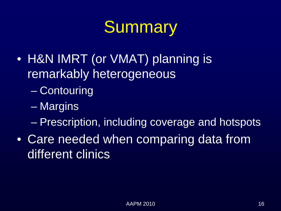
Summary
• H&N IMRT (or VMAT) planning is remarkably heterogeneous– Contouring– Margins– Prescription, including coverage and hotspots
• Care needed when comparing data from different clinics

The Use of IMRT in the Treatment of Head and Neck Cancer
Deborah Schofield, MS, DABRDana Farber / Brigham and Women’s Cancer Center
Harvard Medical School, Boston, MA
Current Address: Baptist Cancer Institute - Jacksonville, FL
Immobilization and Localization
Treatment Planning Tips

Acknowledgements
Roy Tishler, MD, PhD – Dana FarberTracy Balboni, MD – Dana Farber
David Sher, MD – Dana FarberLaurence Court, PhD – MD Anderson
Chuck Mayo, PhD – Mayo Clinic
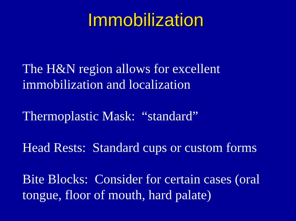
ImmobilizationImmobilization
The H&N region allows for excellent immobilization and localization
Thermoplastic Mask: “standard”
Head Rests: Standard cups or custom forms
Bite Blocks: Consider for certain cases (oral tongue, floor of mouth, hard palate)
ImmobilizationImmobilization
Notes of Caution:
(1) Good Immobilization does NOT always equal good localization
(2) Continuous evaluation of immobilization performance throughout the treatment

LocalizationLocalization
Verification of localization can be accomplished with orthogs
For MV Imaging, the dose delivered during daily imaging can be accounted for and included in a final plan sum and DVH’s.

Daily ImagingDaily ImagingStudy at DF/BWH Cancer Center retrospectively Study at DF/BWH Cancer Center retrospectively evaluated patient setup based on daily ports evaluated patient setup based on daily ports (Court, et al, JACMP, 9(3), 2008)(Court, et al, JACMP, 9(3), 2008)
Isocenter: within 3mm for a median of 92.5% Isocenter: within 3mm for a median of 92.5% patients. patients.
Shoulders: 30% of repositioning involved Shoulders: 30% of repositioning involved shoulder shifts shoulder shifts >> 1cm!1cm!20% patients required 20% patients required >> 1 cm 1 cm shoulder shifts for 7/35 fraction shoulder shifts for 7/35 fraction same direction/patientsame direction/patient

Example of Shoulder ShiftExample of Shoulder Shift
7
Good Agreement at Iso
7mm Shoulder Shift

Overview
- Immobilization and Localization
- Treatment Planning Tips- Routine Cases- Extended Disease- Sinus- Retreatments

Routine CasesRoutine Cases-- Typical plan consists of 7 Typical plan consists of 7 –– 9 beam angles 9 beam angles
-- The beams do not need to be evenly spaced. The beams do not need to be evenly spaced. Instead they should be based on a critical Instead they should be based on a critical evaluation of patient anatomy and target evaluation of patient anatomy and target geometrygeometry
-- Beams should avoid (fixed jaws):Beams should avoid (fixed jaws):-- Entering through bite blocks Entering through bite blocks -- ShouldersShoulders-- Compressed shoulder area on larger patientsCompressed shoulder area on larger patients

Bite Block Shoulders

Objectives (DFCI/BWH)Objectives (DFCI/BWH)CoverageCoverage ““GoodGood”” coverage of PTVcoverage of PTV
Look at 100% and 98% coverageLook at 100% and 98% coverage
Hot SpotsHot Spots << 5%5%
CordCord < 46 Gy< 46 Gy
Exp Cord (7mm)Exp Cord (7mm) 50Gy isodose line shouldn50Gy isodose line shouldn’’t crosst cross
ParotidParotid Mean dose ~ 26 (contralateral)Mean dose ~ 26 (contralateral)
Uninvolved Larynx / Uninvolved Larynx / post cricoidpost cricoid
As low as possibleAs low as possibleMean < 30 GyMean < 30 Gy
Oral cavityOral cavity No hot spots outside volumes and no No hot spots outside volumes and no hot spots in the mandiblehot spots in the mandible

How to Treat the S/CHow to Treat the S/C
Four possible approaches:Four possible approaches:
(1)(1) Treat full extent with IMRTTreat full extent with IMRT(2) (2) Single isocenter IMRT matched to Single isocenter IMRT matched to
LANLAN(3)(3) IMRT matched to a stepped wedge IMRT matched to a stepped wedge
LAN (UAB Technique)LAN (UAB Technique)(4)(4) Larynx sparing extended field IMRTLarynx sparing extended field IMRT

Full Field IMRT
- No matchline issues
- Excellent coverage of deep seated neck nodes
- increased dose to the uninvolved larynx
- brachial plexus

Single Isocenter Matched to Single Isocenter Matched to Static LAN FieldStatic LAN Field
-- IMRT in the superior regionIMRT in the superior region-- LAN field for inferior regionLAN field for inferior region-- Limitations in the field size Limitations in the field size
(Nasopharynx)(Nasopharynx)-- In homogeneities at matchlineIn homogeneities at matchline-- Study from Wash U, found Study from Wash U, found
that 19% of their failures that 19% of their failures occurred at the matchlineoccurred at the matchline**
**Thorstad, et al., IJROBP, V63(2), p.S74, Thorstad, et al., IJROBP, V63(2), p.S74, 2005.2005.
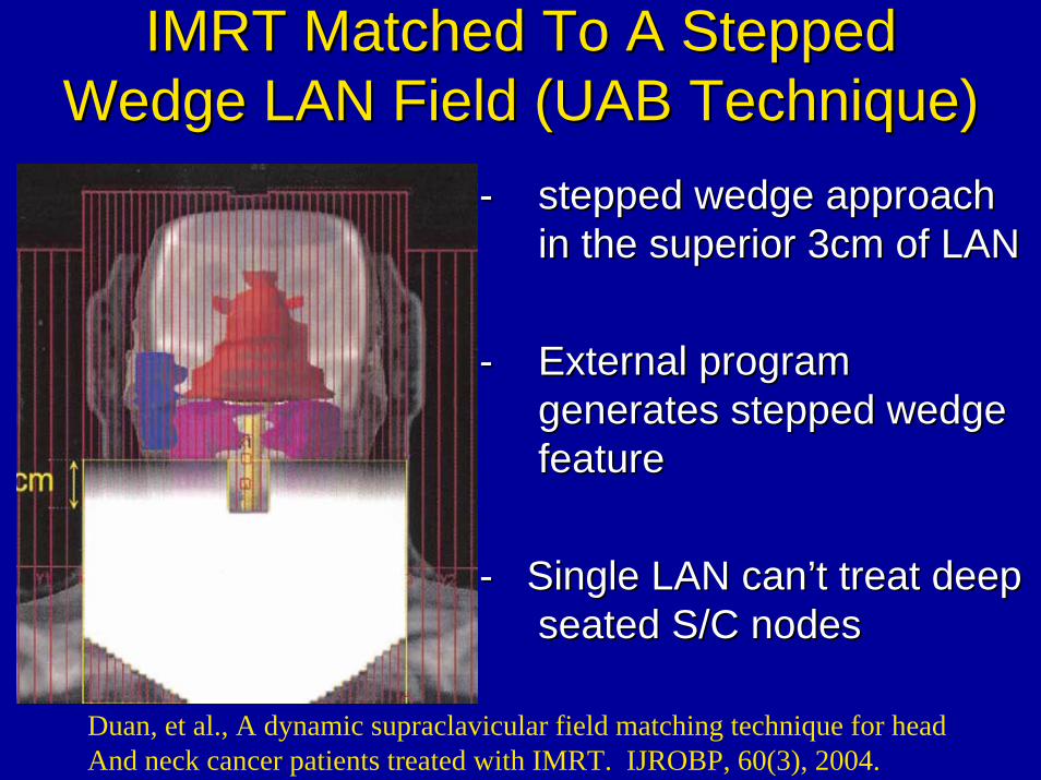
IMRT Matched To A Stepped IMRT Matched To A Stepped Wedge LAN Field (UAB Technique)Wedge LAN Field (UAB Technique)
-- stepped wedge approach stepped wedge approach in the superior 3cm of LANin the superior 3cm of LAN
-- External program External program generates stepped wedge generates stepped wedge featurefeature
-- Single LAN canSingle LAN can’’t treat deep t treat deep seated S/C nodesseated S/C nodes
Duan, et al., A dynamic supraclavicular field matching technique for head And neck cancer patients treated with IMRT. IJROBP, 60(3), 2004.

Larynx Sparing IMRT (DFCI)Larynx Sparing IMRT (DFCI)-- AP/PA type fields treat AP/PA type fields treat
disease at/below larynx disease at/below larynx -- split split into LT and RT components into LT and RT components
-- inferior edge of other beams inferior edge of other beams are fixed at the top of the are fixed at the top of the larynx larynx
-- No field Size limitation or No field Size limitation or matchline issuesmatchline issues
-- Can treat deep seated nodesCan treat deep seated nodes

Larynx Sparing IMRT*Larynx Sparing IMRT*
*Schofield, D., Tishler, R., Balboni, T., Court, L., Sher, D. Reduction of Larynx Dose in Head and Neck IMRT: A Restricted Field Approach.
AAPM National Meeting, 2009. Anaheim, California

Overview
- Immobilization and Localization
- Treatment Planning Tips- Routine Cases- Extended Disease- Sinus- Retreatments

Low smoothing- yields more complex fluence- smaller leaf gaps
High Smoothing- yields less complex fluences- larger leaf gaps- not as conformal for complex geometries- less susceptible to interplay effects
Differential Smoothing IMRT for Thyroid/ Differential Smoothing IMRT for Thyroid/ H&N Disease with extension into H&N Disease with extension into
Mediastinum*Mediastinum*
*Schofield, D., Tishler, R., Court, L. Differential Smoothing IMRT Planning for Head and Neck Cancer Patients with Mediastinal Involvement. AAPM National
Meeting, July, 2006. Orlando, Florida.

Planning StrategyPlanning StrategySingle Isocenter
Neck:- 7-9 low smoothing rate beams - 5mm PTV expansions
Mediastinum:- 3-4 high smoothing rate beams- PTV expansions based on
respiratory motion

Lung Doses MLD: 11.9Gy V20: 20.5%V5: 49.8%

Overview
- Immobilization and Localization
- Treatment Planning Tips- Routine Cases- Extended Disease- Sinus- Retreatments

Sinus / Nasal CavitySinus / Nasal Cavity
•• This site can be difficult to treat because of This site can be difficult to treat because of the proximity of the target volumes to the the proximity of the target volumes to the optic structures.optic structures.
•• OAROAR’’ss-- Globes and Optic NervesGlobes and Optic Nerves-- ChiasmChiasm-- lacrimal glandslacrimal glands-- brainstembrainstem

TechniqueTechnique
Gantry Angles: 90°, 270°
Couch: 0°
Gantry Angles: 340°, 0°, 30°, 60°, 90°
Couch: 90°
IMRT for paranasal sinus and Nasal Cavity Tumors. Duthoy and De Neve, ‘IMRT for paranasal sinus and nasal cavity (sino-nasal) tumors’, Image Guided IMRT
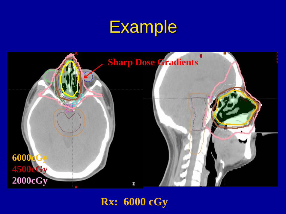
ExampleExample
6000cGy4500cGy2000cGy
Sharp Dose Gradients
Rx: 6000 cGy
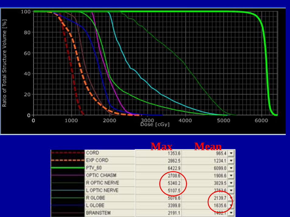
Max Mean

Overview
- Immobilization and Localization
- Treatment Planning Tips- Routine Cases- Extended Disease- Sinus- Retreatments

RetreatmentsRetreatments•• Retreatments are difficultRetreatments are difficult•• Often have to deliver high dose (>50Gy) in Often have to deliver high dose (>50Gy) in
close proximity to OARclose proximity to OAR’’s that have already s that have already received (up to) tolerance dosereceived (up to) tolerance dose
•• Often need high number of beam/couch Often need high number of beam/couch anglesangles
•• Use fixed jaws to protect OARUse fixed jaws to protect OAR’’ss•• Cord / expanded cord dose limits:Cord / expanded cord dose limits:
Cord: 10Cord: 10--12Gy12GyExpanded cord: 15GyExpanded cord: 15Gy

Example: Sinus Retreat
~2mm
Patient had been previously Treated to the sinus
Optics: Previously treated to Full tolerance
Recurrence: ~ 1yr after radiationGTV ~ 2mm fromoptics

Beam ConfigurationBeam Configuration
11 Beams, 7 couch angles Fixed Beams

For OptimizationFor Optimization
3mm margins on Optics
Sup dummy “PTV”pulled away from optic structures
Unmodified inferior PTV

Results
Dose fall off:50Gy to 20 Gy < 1cm

Educational ObjectiveDiscuss different approaches for the use of IMRT for treating head and neck tumors.
We discussed:- immobilization and localization- routine cases including 4 approaches for the treatment of the S/C
- H&N with extension into the mediastinum- sinus- re-irradiation

Review and guidelines for treating Review and guidelines for treating head and neck tumors using IMRT head and neck tumors using IMRT
and VMATand VMAT
VolumeVolume--Modulated Arc Modulated Arc Therapy Therapy
Charles Mayo, Ph.D.Charles Mayo, Ph.D.
Mayo ClinicMayo Clinic
Rochester, MNRochester, MN
WE‐B‐203‐1Wednesday 8:30 am ‐9:25 am Room 203

DisclosureDisclosure
•• Grant support from Varian Medical Grant support from Varian Medical SystemsSystems

Where we thought the challenges would lie and where they actually did emerge.
Probability of gettingthe desired plan
The Learning Curve
Moving from here to here
•• Brief review of VMATBrief review of VMAT•• Advantages / disadvantages of VMAT vs. IMRT Advantages / disadvantages of VMAT vs. IMRT •• Tips on planning VMAT casesTips on planning VMAT cases•• Comparison of VMAT and IMRT plans (including some Comparison of VMAT and IMRT plans (including some
special cases covered in IMRT portion)special cases covered in IMRT portion)•• Table attenuation correctionTable attenuation correction•• QA for QA for RapidArcRapidArc (? Depends on time)(? Depends on time)
OutlineOutline

What is Volumetric Modulate Arc What is Volumetric Modulate Arc Therapy (VMAT)?Therapy (VMAT)?
•• IMRT modulates IMRT modulates MLCMLC’’ss during beam on to shape the 2D beam during beam on to shape the 2D beam profile on a fixed angle beam. Combine beams for a 3D dose profile on a fixed angle beam. Combine beams for a 3D dose distribution.distribution.
•• VMAT modulates VMAT modulates MLCMLC’’ss, gantry speed, dose rate during beam , gantry speed, dose rate during beam on to shape the 3D dose distribution from arc beams.on to shape the 3D dose distribution from arc beams.
•• Available in most treatment planning systemsAvailable in most treatment planning systems
•• Eclipse (Eclipse (RapidArcRapidArc) ) examples in this presentationexamples in this presentation•• Pinnacle (Smart Arc)Pinnacle (Smart Arc)•• CMS (Monaco with VMAT)CMS (Monaco with VMAT)

Why VMAT?Why VMAT?•• Fewer BeamsFewer Beams
•• 22--3 Arcs 3 Arcs vsvs 99--18 (carriage splits)18 (carriage splits)
•• Improves QA processImproves QA process•• Improves 2Improves 2ndnd check process on planscheck process on plans•• Reduces time for QA measurementsReduces time for QA measurements
•• Shorter Treatment TimeShorter Treatment Time•• Patient satisfactionPatient satisfaction•• Reduced potential for intraReduced potential for intra--fraction motionfraction motion•• Better utilization of FTE and technology resourcesBetter utilization of FTE and technology resources•• Create more available time for IGRTCreate more available time for IGRT

Why VMAT?Why VMAT?
•• Potential for improved planningPotential for improved planning
•• Arc distributions help reduce intermediate dose level Arc distributions help reduce intermediate dose level exposures. exposures.
•• Difficult to over modulate a Difficult to over modulate a RapidArcRapidArc beam. Less likely to beam. Less likely to fail in QA measurements when normal tissue constraints fail in QA measurements when normal tissue constraints are pushed.are pushed.
•• TemplatedTemplated approach to planning that may raise the bar on approach to planning that may raise the bar on base plan quality.base plan quality.

Basic planning approach: we use the same contouring based approach to planning for RapidArc that we developed and reported for IMRT many years ago.
CTV
PTV
IMRT PTV• Optimize on the IMRT PTV• Margin to compensate for shoulders
on profile• Modify to reflect normal tissue
compromises
Dose Limiting Annulus• To control intermediate dose levels
Normal Tissue to Avoid • Contour actual anatomy• Add separate buffer structures as needed
C.Mayo, Ph.D.
In several of the clinical examples to follow you will see extensions of this basic contour orient approach to planning.
Important to follow ICRU definitions

Dose Sculpting StructuresDose Sculpting Structures
DLA: Defines intermediate dose region for dose reduction
Buff: Specifies sub‐region between target volumes to drive out “hot” spots
PTV 60 GyPTV 54 Gy IMRT PTVs are cropped back from surface by 4 mm.
Optimize to IMRT PTV Normalize/Evaluate PTV
Charles Mayo, Ph.D.

Contouring Contouring –– TargetsTargetsOverlap at junctionOverlap at junction
GTVCTVPTV
IMRT-PTV
Overlap at junction

Contouring Contouring –– TargetsTargetsFix with IMRT PTVFix with IMRT PTV
54 Gy IMRT PTV
60 Gy IMRT PTV
Crop IMRT PTVs in overlap region to reflect which gets the higer priority for coverage. More intuitive than trying to do this in the optimizer with overlapping structures.

Normal StructuresNormal StructuresIt is important to try to contour the actual anatomic structures, in order to make meaningful comparisons of normal tissue constraints or complications.
Use buffer or sculpting structures to control dose gradients.

Dose Sculpting StructuresDose Sculpting StructuresCord BufferCord Buffer
Contour normal structures to be anatomically correct. Include a buffer on normal tissues to control gradient of dose near to normal tissue.
Contour cord, not spinal canal. Use cord buffer structure in optimization to control gradient near cord.

2 Level DLA2 Level DLA
For dose painting (e.g. 60 Gy and 54 Gy targets) two DLA’s may be helpful.

Beam SelectionBeam Selection

Beam SelectionBeam Selection

Control PointsControl Points

Control PointsControl PointsGet other beam 126 Get other beam 126 vsvs 177177

Beam SelectionBeam SelectionTwo Dose Levels (60Gy/54Gy)Two Dose Levels (60Gy/54Gy)
1) Clockwise 2) Counter Clockwise3) Partial On High Dose Volume
Total of 732 MU and 483 control points with RapidArc vs.1260 MU and 2020 control points for 9 field IMRT with carriage splits. More efficient use of MU’s and MLC’s to deliver the same dose.

Is it complicated to design the Is it complicated to design the constraints?constraints?
Start simple to understand the Start simple to understand the behavior then refine.behavior then refine.

Is it complicated to design the Is it complicated to design the constraints? constraints? Minimal OptimizationMinimal Optimization
If you just push on the constraints to have a conformal dose distribution, how do the dose levels in the normal structures turn out?
Cover IMRT PTV’sMinmize High dose in DLA’sUse NTO

Is it complicated to design the Is it complicated to design the constraints? constraints? Minimal OptimizationMinimal Optimization
VMAT IMRT
Original IMRT plan was designed with specific constraints for the normal tissues.
Simple approach to VMAT produced lower dose in
• L Parotid• Phar Constrictors
Higher dose in
• Cord• R Parotid
We can do better with more and specific constraints, but this simplistic approach takes us well along the way to a desirable plan.
IMRT (squares)RapidArc (triangles)

Is it complicated to design the Is it complicated to design the constraints? constraints?
Try IMRT constraints on a first pass at a VMAT plan Try IMRT constraints on a first pass at a VMAT plan
Should we consider a VMAT plan instead of the current IMRT plan?
As a first pass, try re-optimizing with the same constraint set and the set of 3 VMAT beams.
Thanks to Shelly Ward
VMAT IMRT

Setting the Normal Tissue Objective (NTO)Setting the Normal Tissue Objective (NTO)
If you are not sure what parameters to use• Optimize without the NTO• Use the dose profile tool discover what fall
off is reasonable•Set NTO parameters to push it reasonably
• If the NTO is over constrained (i.e. physically unreasonable dose distribution) the results can be poor.

Optimization ConstraintsOptimization ConstraintsIMRT PTVIMRT PTV
Since IMRT PTV has been contoured to reflect reasonable expectation of high dose (avoid buildup near skin, avoid overlap of normal tissues to be spared, differing dose levels, etc) set constraints to cover IMRT PTV.

Optimization ConstraintsOptimization ConstraintsBuffBuff
Leverage ability, to hold RapidArcoptimizationat an early level (e.g. 2), to take your time to look at specific structure constraints one by one and avoid a cluttered screen.

Optimization ConstraintsOptimization ConstraintsParotidParotid
Drive mean parotid dose low, by pushing on the low dose portion of the DVH curve.

Optimization ConstraintsOptimization ConstraintsSpinal CordSpinal Cord
Set max on cord, then drive volume of cord buffer structure at that dose level to a lover volume.
Cord max
Cord Buffer

Optimization ConstraintsOptimization ConstraintsAll TogetherAll Together

Comparison of IMRT and Comparison of IMRT and RapidArcRapidArc
How quickly to planners climb the learning curve?
Clinical examples of cases where planners decided that they preferred the VMAT dose distribution.
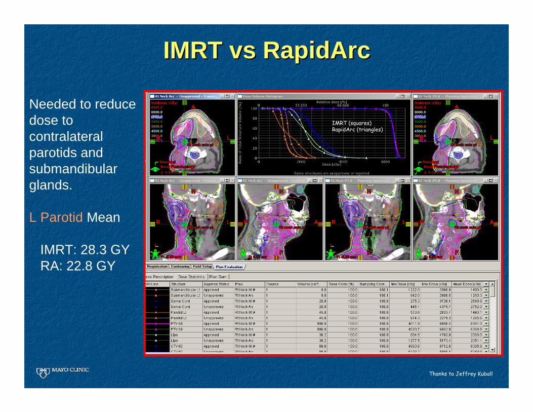
IMRT IMRT vsvs RapidArcRapidArc
Thanks to Jeffrey Kuball
Needed to reducedose to contralateralparotids and submandibularglands.
L Parotid Mean
IMRT: 28.3 GY RA: 22.8 GY
IMRT (squares)RapidArc (triangles)
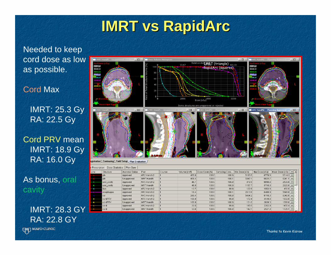
IMRT IMRT vsvs RapidArcRapidArcNeeded to keep cord dose as low as possible.
Cord Max
IMRT: 25.3 GyRA: 22.5 Gy
Cord PRV meanIMRT: 18.9 GyRA: 16.0 Gy
As bonus, oral cavity
IMRT: 28.3 GY RA: 22.8 GY
Thanks to Kevin Kisrow
IMRT (triangle)RapidArc (squares)

IMRT IMRT vsvs Rapid ArcRapid Arc
IMRTRapidArcRapidArcgave very conformal dose distribution with significant reduction in dose to contralateralparotid and pharyngeal constrictors
Thanks to Janelle Miller, Dr Louis Fong de los Santos, Jeffrey Kuball

IMRT IMRT vsvs Rapid ArcRapid Arc
IMRTRapidArcIMRT did better on reducing max larynx dose. For overall larynx dosedistribution, RapidArc is lower

IMRT IMRT vsvs Rapid ArcRapid ArcIMRT (squares)RapidArc (triangles)
Significant gains with RapidArc for
L ParotidConstrictorsCord
IMRT better for
EsophagusLarynx max
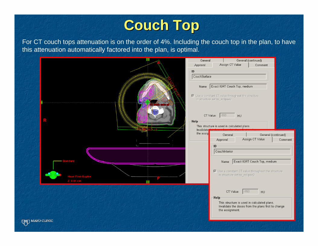
Couch TopCouch TopFor CT couch tops attenuation is on the order of 4%. Including the couch top in the plan, to have this attenuation automatically factored into the plan, is optimal.

On the learning curve
Remember a lesson learned during IMRT about perceptions of new technology
p(E) = p(E|Q) p(Q)
Probability that the planner gets a better Rapid Arc Plan
Probability that VMAT technology is capable of a better plan
Given that the technology is capable, probability that the planner gets a better Rapid Arc Plan
1
0
p(E|Q)
The Learning Curve
Is the plannerhere
or here?
Not getting the plan we want could be p(Q) but it could also be p(E|Q).
Avoid temptation to judge a new technology, before staff have time to master it.

SummarySummary
VMAT is emerging as a main stream treatment planning/delivery option
•Supported by multiple vendors•Expanding number of facilities making use of the technology
VMAT does not have to mean compromise in sparing of normal tissues
VMAT planning can build upon IMRT planning approaches to facilitate transition, however additional “tricks” may be needed to get the most out of it.
There is a learning curve for getting good VMAT plans. Once there it becomes the preferred approach.
