results of a laboratory experiment that tests rotating ...€¦ · results of a laboratory...
TRANSCRIPT
NASATechnical
Paper3458
1994
National Aeronautics andSpace Administration
Office of ManagementScientific and TechnicalInformation Program
Results of a Laboratory Experiment That
Tests Rotating Unbalanced-Mass Devices
for Scanning Gimbaled Payloads and
Free-Flying Spacecraft
(CDDF Final Report No. 92-02)
D.C. Alhorn and M.E. Polites
George C. Marshall Space Flight Center
Marshall Space Flight Center, Alabama
https://ntrs.nasa.gov/search.jsp?R=19940019101 2020-04-30T23:22:43+00:00Z

TABLE OF CONTENTS
I. INTRODUCTION ...............................................................................................................
II. THE BASIC THEORY OF SCANNING WITH RUM DEVICES ....................................
III. THE EXPERIMENT FOR TESTING RUM DEVICES .....................................................
IV. PROCEDURES FOR TESTING THE RUM DEVICES ....................................................
V. TEST RESULTS FOR LINEAR SCANNING ...................................................................
VI. TEST RESULTS FOR CIRCULAR SCANNING ..............................................................
VII. CONCLUSIONS AND COMMENTS ...............................................................................
REFERENCES ...............................................................................................................................
Page
1
2
7
11
13
20
28
30
FzRECClIDI_II PAGE BLANK NOT
t
'PAGE_ 1 ( INTENTIONALLYBLANK ...-- 111
F,N.MED

LIST OF ILLUSTRATIONS
Figure
1.
.
3.
4.
5.
6.
7.
8.
9.
10.
11.
12.
13.
14.
15.
16.
17.
Title
Concept of an experiment to test RUM devices for linear, raster, and
circular scanning ..........................................................................................................
Definition of the RUM parameters ..............................................................................
Definition of the elevation and cross-elevation gimbal angles ....................................
Photograph of the completed RUM experiment ..........................................................
Dean Alhorn at the host computer and Mike Polites at the emulated payload ............
A close-up of two RUM devices mounted on one end of the payload ........................
Control system block diagram for the RUM servos ....................................................
Control system block diagram for the cross-elevation servo .......................................
Control system block diagram for the elevation servo ................................................
RUM experiment test results for linear scanning
with RUM's and gimbal servos at 0 ° elevation angle ..................................................
RUM experiment test results for linear scanning
with gimbal servos only at 0 ° elevation angle ..............................................................
RUM experiment test results for linear scanning
with RUM's and gimbal servos at -90 ° elevation angle ..............................................
RUM experiment test results for linear scanning
with gimbal servos only at -90 ° elevation angle ..........................................................
RUM experiment test results for circular scanningwith RUM's and gimbal servos at 0 ° elevation angle ..................................................
Computer simulation results for circular scanningwith RUM's and gimbal servos at 0 ° elevation angle ..................................................
RUM experiment test results for circular scanning
with gimbal servos only at 0 ° elevation angle ..............................................................
RUM experiment test results for circular scanning
with RUM's and gimbal servos at-90 ° elevation angle ..............................................
Page
3
4
5
8
8
8
10
10
10
14
16
18
19
21
23
24
25
iv


LIST OF ILLUSTRATIONS (Continue)
Figure
18.
19.
Title
Computer simulation results for circular scanningwith RUM's and gimbal servos at -90 ° elevation angle ..............................................
RUM experiment test results for circular scanning
with gimbal servos only at-90 ° elevation angle ..........................................................
Page
26
27
LIST OF TABLES
Table Title Page
.
2.
Summary of results from RUM experiment for linear scanning .................................
Summary of results from RUM experiment for circular scanning ..............................
15
22
V


TECHNICAL PAPER
RESULTS OF A LABORATORY EXPERIMENT THAT TESTS ROTATING
UNBALANCED-MASS DEVICES FOR SCANNING GIMBALED
PAYLOADS AND FREE-FLYING SPACECRAFT
(MSFC Center Director's Discretionary Fund Final Report,
Project Number 92--02)
I. INTRODUCTION
Space-based and balloon-borne gimbaled scientific instruments often require scanning to meettheir scientific objectives. The same is true of some free-flying spacecraft. See references 1 to 3 for
examples of these. Sometimes, the only possible way to achieve a meaningful scan is to scan the entire
instrument or spacecraft. This is true for x-ray and gamma-ray telescopes. The scan patterns required areoften linear scans, raster scans, or circular scans. A linear scan is characterized by the instrument or
payload line-of-sight repeatedly moving back-and-forth in a line centered on the target. A raster scan is
like a linear scan except with some slow complementary motion in a direction perpendicular to the
scanning motion. The complementary motion could be a ramp, a saw-toothed waveform, or steppingmotion. Circular scans are characterized by the payload line-of-sight repeatedly tracing out a circle
centered on a target.
Gimbaled payloads mounted to space platforms, like the space shuttle or a space station, can be
scanned using gimbal-mounted torque motors. However, this approach requires a great deal of power
when the payload is large and the scan frequency is high, because the torque motors must continuously
accelerate and decelerate the payload very rapidly. Also, this generates large cyclic reaction torques on
the mounting base that can excite local structural resonances, causing scanning or stability problems. To
help the stability problem, the mounting base would need to be stiffened, which could add considerable
mass to the base. In addition, scanning at high frequencies with some precision can require high gimbal
servo bandwidths, which may also be difficult to achieve. A large payload inertia and mass, interacting
with any structural flexibility in the gimbals or the torque motors, can produce low-frequency structuralresonances which severely limit the servo bandwidth that is attainable with a stable control system.
Scanning large payloads at high frequencies means large gimbal torque motors, which have more
cogging, ripple, and friction than small ones. With a digital implementation for the gimbal servos, thetorque commands to large torque motors have more quantization than those to small torque motors. All
of these problems can degrade scanning accuracy. Using control moment gyroscopes (CMG's) or
reaction wheels, in place of gimbal torque motors, does not require torquing against the mounting base,
but does not eliminate the other problems.
The problems with scanning balloon-borne gimbaled payloads using torque motors, CMG's, or
reaction wheels are worse than those just described. Now the gimbaled payload is mounted to a gondola,
which has much less mass than the space shuttle or a space station. In fact, it may have less mass than
the payload being scanned. What is worse, the gondola attaches to a set of shroud lines, which in turnattaches to a balloon. Therefore, the plant dynamics are extremely complex, which exacerbates the
scanning problems.

Obviously,free-flying spacecraftcannotbescannedwith gimbaltorquemotors;but theycanbescannedwith CMG's or reactionwheels.The plantdynamicsof afree-flyingspacecraftaremorebenignthanthoseof a balloon-bornegimbaledpayload,but theotherproblemswith scanningalargepayloadathigh frequenciesarejust asbad.
References4 through7 describea new approachto scanningspace-basedand balloon-bornegimbaledpayloads,free-flying spacecraft,aswell asground-basedgimbaledpayloads.It usesa pair ofrotating unbalanced-mass(RUM) devices,mountedon thepayloador spacecraft,to generatethe basicscanmotion andanauxiliary controlsystem(ACS) which: (1)keepsthescancenteredon thetargetand(2) producesa complementarymotion for rasterscanning.The ACS can usegimbal torque motors,CMG's, or reactionwheels,dependingon theapplication,but is not requiredto haveahigh bandwidth.Rather,it only has to generatelow-frequency,low-amplitudetorquesto satisfy its requirements.Thus,largecyclic reactiontorquesagainsta mountingbaseor gondolaareavoidedwhenRUM's areusedforscanning.The analysisandcomputersimulationresultsin references4 and5 showthat gimbaledpay-loadsandfree-flying spacecraftcanscanmoreaccuratelyandwith much lesspowerwhenRUM's areused.However,theseclaimshaveneverbeenprovenby actualhardwaretesting,until now.
This paper describesan actual laboratory experiment that tests the concept of scanning agimbaledpayloadwith RUM devices.Testresultsfrom theexperimentarepresented,which prove theconcept.The outline of the paperis asfollows. SectionII presentsthe basictheory of scanningwithRUM devices.SectionIII describesin detail the laboratoryexperimentfor testingRUM's. SectionIVcoversthe proceduresusedin testing.SectionV presentsthetestresultsfor linear scanning,with andwithout RUM's, and comparesthesewith results from a computersimulation model. SectionVI issimilar to sectionV, exceptfor circularscanning.SectionVII offersconclusionsandfinal comments.
II. THE BASIC THEORY OF SCANNING WITH RUM DEVICES
The basic concept of a RUM device can be explained with the help of figures 1 and 2, whichshow a gimbaled I-beam as an emulated payload to be scanned. A pair of RUM's is mounted on top of
the I-beam for linear scanning in cross-elevation. Another pair is mounted on the lower side for circular
scanning.
A RUM device is simply a mass, m, on a lever arm, r, rotating at a constant angular velocity,
co = m , (1)rp
where Tp is the period of rotation of the mass. This generates a centrifugal force, mco2r, on the payload.
Mounting the RUM device at a distance, d, from payload center-of-mass generates a cyclic torque, about
the center-of-mass, with an amplitude equal to moo2rd.

CROSS-ELEVATION
AXIS
P3
LINEAR
RUM #1
P1
OF SIGHT
CIRCULAR
RUM #1
P2
ELEVATION
AXIS
LINEAR
RUM #2
ELEVATION
MOTOR
CIRCULAR
RUM #2
CROSS-
ELEVATION
MOTOR
GRAVITY 1
VECTOR g
Figure 1. Concept of an experiment to test RUM devices for linear, raster, and circular scanning.

P1
oR #ir
LINEAR
RUM #1 m d
T
p2 "_'------ q_P:
d
J
m
LINEAR
)?UM #2
PI
OR
rCIRCULAR
m RUM #2
(a)View looking down P3 axis
showing finear RUMparameters.
(b)View lookingalong Pl axis
showing circularRUM
parameters.
CIRCULARRUM #1
p2.6.-----
m
d
V
_P5
dCIRCULARRUM #2
m
(c)
View looking along P3 axisshowing circular RUM
parameters.
Figure 2. Definition of the RUM parameters.
4

WhenthetopRUM's in figure 1aremaintained180°out-of-phaseastheyrotateaboutthecross-elevationaxis (P3),thenet torqueis cyclic in thecross-elevationaxisandhasamagnitudeof 2mo92rd.WhentheRUM positionsaredefinedby theangleOk in figure 2-aand
2zr (2)OR= COt= _t ,G
then the net torque in cross-elevation becomes
Tx = 2mto2rdcos(OR)= 2mogZrdcos[ 2_rt] .J
(3)
Using the definitions for the payload cross-elevation angle O x and elevation angle O e shown in
figure 3, the payload equation-of-motion in cross-elevation can be approximated by
Ox = -_- , (4)
where I is the payload moment-of-inertia in the cross-elevation axis. Equation (4) neglects any friction
in the system and assumes perfect cancellation of the reaction torques on the payload caused by any
Cross-Elevation - P3Axis
0 E
LocalHorizontal
0 E
ElevationAxis
Figure 3. Definition of the elevation and cross-elevation gimbal angles.
5

gravity torqueson the RUM masses.Substitutingequation(3) into equation(4) and integratingtwicegivesthesteady-statescanmotion:
As expected,thisrepresentslinearscanmotionin thecross-elevationaxiswith anamplitude
2mrdp - (6)
I
and a period Te, the same as the period of rotation of the RUM's. Hence, changing the lever arm of the
RUM devices is a convenient way to change the scan amplitude. Similarly, a simple way to change the
scan period is to change the RUM period of rotation, since both are equal to Te.
When the lower RUM's in figure 1 are maintained 180" out-of-phase as they rotate about the
payload line-of-sight (P1), the net torque is now cyclic in both the cross-elevation and elevation axes and
has a magnitude of 2mco2rd. When the RUM positions are specified by the angle O R in figure 2-b and
O R as a function of time is defined by equation (2), then the net torques in the cross-elevation and
elevation axes are, respectively,
F_,,. 1T x = +2mco2rdcos(OR)= +2mco2rd cos|"" t|
Lr, J(7)
F_.,. 1
T e = -2mto2rdsin(OR)= -2mo92rdsin|""t|Lr J
(8)
Using the definitions for the payload cross-elevation angle O x and elevation angle O e shown in
figure 3, the payload equations-of-motion in cross-elevation and elevation can now be approximated by
Ox = ? (9)
OE = Te (10)I
respectively, when I is the payload moment-of-inertia in both the cross-elevation and the elevation axes.
Again, equations (9) and (10) neglect any friction in the system and assume exact cancellation of the
reaction torques on the payload caused by any gravity torques on the RUM masses. Substituting
equations (7) and (8) into equations (9) and (10), respectively, and integrating twice gives the steady-state scan motion
Ox- 2mrdcosr2"tl=-pcosF2.tl (11)
I j j
6

+ sinr: .,l=+ps,,,[2.,,l (12)
Clearly, this is circular motion of the payload line-of-sight. The scan radius is p and specified by
equation (6); the scan period is T e, the same as the RUM's period of rotation. Like before, changing the
lever arm of the RUM devices is a convenient way to change the scan radius and changing the RUM's
period of rotation changes the scan period.
With either linear or circular scanning, the RUM's are required to rotate at a constant angular
velocity and stay 180" out-of-phase with each other. To achieve this, each RUM device requires a servo
with a torque motor and an angular position sensor, like an optical encoder. If the scan rates are not too
high, the feedback controller for both servos can be implemented digitally in a single microcontroller;
otherwise, analog electronics are recommended. Other implementations for the RUM servos are
possible. For example, resolvers can be used in place of encoders; and tachometers could be added forrate feedback.
To keep the RUM-generated scan on target and produce the complementary motion for raster
scanning, the ACS is needed. The commands to the ACS need to be synchronized with the motion of the
RUM's, so tliat the ACS does not fight the scan motion generated by the RUM's. For the gimbaled
I-beam in figure 1, the ACS employs the gimbal torque motors.
The choice of the payload sensors depends on the target to be scanned and the application. For
example, if the payload scans the Sun, a payload-mounted two-axis Sun sensor is recommended. A pay-load mounted two-axis rate gyro can be added for rate feedback. To simply demonstrate the concept of
scanning with RUM devices, gimbal encoders or resolvers are sufficient for position information and
gimbal-mounted tachometers can be added for rate feedback. If the RUM servos have a microcontroller,it can also be used to solve the control algorithms for the ACS.
lII. THE EXPERIMENT FOR TESTING RUM DEVICES
Initially, an experiment was conceived to test a pair of RUM devices for linear and raster
scanning a gimbaled payload. A detailed design was performed and a computer simulation model was
developed to verify the design. This is documented in reference 8. Then, modifications to the experimentwere defined in order to reconfigure it for circular scanning. The computer simulation model was also
modified and used to verify the experiment design for circular scanning. See reference 9 for furtherinformation.
Subsequently, it became apparent that the experiment could not be quickly reconfigured for one
type of scanning or another, using only one pair of RUM's. This is because the RUM's have to be
reoriented to change scans and the payload has to be rebalanced to keep its center-of-mass at the inter-section of the cross-elevation and the elevation gimbals. To circumvent this problem, two pairs of
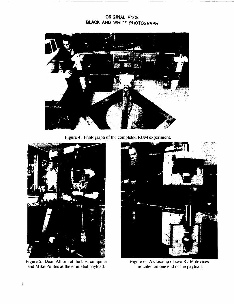
RUM's were used in the final experiment, as shown in figure 1 and in the actual experiment in figures 4
and 5. The top pair of RUM devices was used for linear and raster scanning and the lower pair was used
for circular scanning. In this experiment, only one pair of RUM devices was operated at a time and the
other pair was mechanically locked and powered down. Figure 6 is a close-up of two separate RUM
devices on one end of the payload.
7
ORIGINAL PAGE
BLACK AND WHITE PHOTOGRAPH
Figure 4. Photograph of the completed RUM experiment.
Figure 5. Dean Alhorn at the host computer
and Mike Polites at the emulated payload.
Figure 6. A close-up of two RUM devices
mounted on one end of the payload.
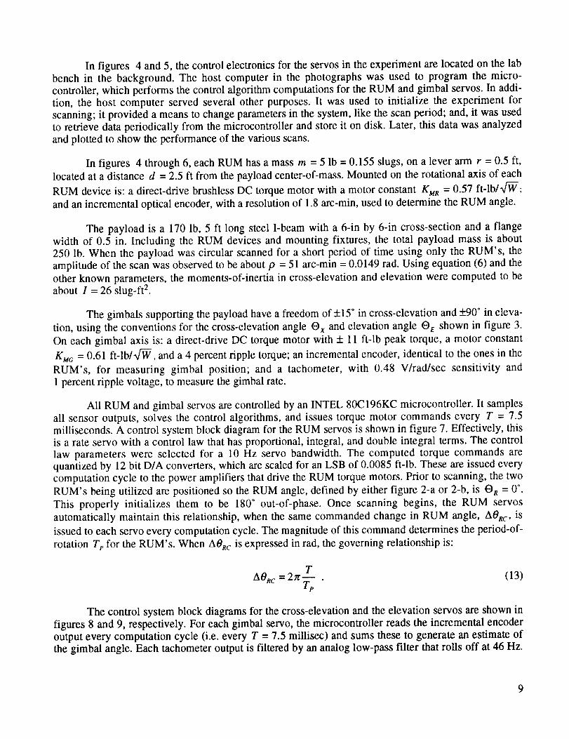
In figures 4 and5, thecontrolelectronicsfor theservosin theexperimentarelocatedon thelabbenchin the background.The host computer in the photographswas used to programthe micro-controller,which performsthecontrolalgorithmcomputationsfor theRUM andgimbal servos.In addi-tion, the host computer servedseveralother purposes.It wasusedto initialize the experiment forscanning;it provideda meansto changeparametersin thesystem,like thescanperiod;and,it wasusedto retrievedataperiodically from themicrocontrollerandstoreit ondisk. Later, thisdatawasanalyzedandplottedto showtheperformanceof thevariousscans.
In figures 4 through6, eachRUM hasa massm = 5 lb = 0.155 slugs, on a lever arm r = 0.5 ft,
located at a distance d = 2.5 ft from the payload center-of-mass. Mounted on the rotational axis of each
RUM device is: a direct-drive brushless DC torque motor with a motor constant KMR = 0.57 ft-lb/a/-W;
and an incremental optical encoder, with a resolution of 1.8 arc-min, used to determine the RUM angle.
The payload is a 170 lb, 5 ft long steel I-beam with a 6-in by 6-in cross-section and a flange
width of 0.5 in. Including the RUM devices and mounting fixtures, the total payload mass is about
250 lb. When the payload was circular scanned for a short period of time using only the RUM's, the
amplitude of the scan was observed to be about p = 51 arc-min = 0.0149 rad. Using equation (6) and the
other known parameters, the moments-of-inertia in cross-elevation and elevation were computed to be
about I = 26 slug-ft 2.
The gimbals supporting the payload have a freedom of +15 ° in cross-elevation and _+90° in eleva-
tion, using the conventions for the cross-elevation angle O x and elevation angle O e shown in figure 3.
On each gimbal axis is: a direct-drive DC torque motor with + 11 ft-lb peak torque, a motor constant
KMG = 0.61 ft-lb/n/-ff, and a 4 percent ripple torque; an incremental encoder, identical to the ones in the
RUM's, for measuring gimbal position; and a tachometer, with 0.48 V/rad/sec sensitivity and
1 percent ripple voltage, to measure the gimbal rate.
All RUM and gimbal servos are controlled by an INTEL 80C196KC microcontroller. It samples
all sensor outputs, solves the control algorithms, and issues torque motor commands every T = 7.5
milliseconds. A control system block diagram for the RUM servos is shown in figure 7. Effectively, thisis a rate servo with a control law that has proportional, integral, and double integral terms. The control
law parameters were selected for a 10 Hz servo bandwidth. The computed torque commands arequantized by 12 bit D/A converters, which are scaled for an LSB of 0.0085 ft-lb. These are issued every
computation cycle to the power amplifiers that drive the RUM torque motors. Prior to scanning, the two
RUM's being utilized are positioned so the RUM angle, defined by either figure 2-a or 2-b, is O R = 0 °.
This properly initializes them to be 180 ° out-of-phase. Once scanning begins, the RUM servos
automatically maintain this relationship, when the same commanded change in RUM angle, AORc, is
issued to each servo every computation cycle. The magnitude of this command determines the period-of-
rotation Tp for the RUM's. When AORc is expressed in rad, the governing relationship is:
AORc = 2_r.-_T (13)rp
The control system block diagrams for the cross-elevation and the elevation servos are shown in
figures 8 and 9, respectively. For each gimbal servo, the microcontroller reads the incremental encoder
output every computation cycle (i.e. every T = 7.5 millisec) and sums these to generate an estimate of
the gimbal angle. Each tachometer output is filtered by an analog low-pass filter that rolls off at 46 Hz.
9

aeRc(kT) Tc(kT)
TG
7o,,au_Moto,,/
Power Amp Friction
i .+ iI_O*R(kT) s
Incremental Eneoder
Figure 7. Control system block diagram for the RUM servos.
rR = T.MCOS(eM
F_i°"I IA/D N
Filter Taeh
........ I
I
I I
_ummer IncrementalEncoder
Figure 8. Control system block diagram for the cross-elevation servo.
rr-O_ -M°-t°!-, I
_q lE -_ Z OH _ ]-_ Jr2E I OE
_ _ _'--_---_-J:[_1 -I
Filter Tach
I I
I I
bummer IncrementalEncoder
Figure 9. Control system block diagram for the elevation servo.
10

The filter output is sampled every computation cycle by a 10 bit A/D converter scaled to a range
of +0.35 rad/sec or +20°/sec. This gives an LSB of about 0.04°/sec. Gimbal angle and rate commands are
computed in the microcontroller every computation cycle. These are synchronized with the RUM motionso the RUM's and the gimbal servos work together synergistically. This is accomplished by summing
the commanded changes in the RUM angle, AORc, each computation cycle, in order to generate the
commanded RUM angle ORc. This is shown in figure 7. Then, ORc is input into the computations for the
gimbal angle and rate commands shown in figures 8 and 9. When only the gimbal servos are used forscanning, the operation is the same except that all four RUM's are mechanically locked and powereddown.
For circular scanning, the constants OxcM and Oecs_ were determined to be:
Oxcsf = 0ec M = p = 51 arc-min = 0.0149 rad. (14)
Here, p was determined by observing the natural scan radius when the RUM's were activated for a short
period of time without the gimbal servos. An alternative is to compute p using equation (6), provided
the system parameters are accurately known. The constants f_xcM and Qecm were determined to be:
2__xcM = _ecM = "_P = 322 arc-min/sec = 5.37°/sec = 0.0937 rad/sec ,
11,(15)
when the scan period Te = 1 sec, which was the baseline for all tests.
For linear scanning, the only difference is
OecM = QecM = 0. (16)
In figure 9, specifying the bias elevation angle command Oeco determines the nominal elevation angle
for circular or linear scanning. Varying Oeco as a function of time generates the complementary motion
for raster scanning.
The control law for each gimbal servo is a proportional-integral controller with rate feedback.
The control gains were chosen for a servo bandwidth of approximately 0.1 Hz. In fact, structural
resonances in the system made it impossible to get a higher bandwidth and still have a stable control
system. In the forward loop of each servo is a digital low-pass filter that rolls off at 2 Hz. It prevents
exciting these structural resonances as much as possible. The output of the digital filter is the torque
command for the gimbal torque motor. Its magnitude is quantized to 8 bits, with each bit corresponding
to about 0.05 ft-lb. The quantized torque command is issued by the microcontroller every computation
cycle to a PWM generator, which in turn drives the power amplifier for the gimbal torque motor.
IV. PROCEDURES FOR TESTING THE RUM DEVICES
Prior to testing the RUM's for scanning, the payload with all four RUM's was roughly mass
balanced. This was accomplished by first locking the RUM's in place and then driving the elevation
servo to a -90 ° elevation angle. The steady state torque command in the elevation servo was then
11
observedusingthe hostcomputer.With this information, themassneededto balancethe1-beamwasdetermined.Then,steelplateswith this massweremountedon theI-beam,asshownin figures4 and5.Thisreducedtheelevationtorquecommandto lessthan1ft-lb, which is small comparedto the 11ft-lbpeaktorqueof theelevationtorquemotor.
To test the RUM devicesfor scanningthepayload,a numberof scanswere performed.Linearandcircularscansweregenerated,with andwithoutRUM devices,atnominalelevationanglesof 0 and-90°. A 0° elevationangle is thebestorientationfor linearscanningwith RUM's, because no gravity
torque acts on them. Therefore, this is like a simulated zero-g test for linear scanning with RUM's. A
-90 ° elevation angle is the worst orientation for linear scanning with RUM's, because the gravity torqueacting on them is a maximum. Just the opposite is true for circular scanning with RUM's. As a result,
these two elevation angles cover both extremes for both types of scanning with RUM's. Scanning with-
out RUM's should give similar results at any elevation angle, when the payload is properly massbalanced. Raster scanning to test RUM devices has one drawback. The entire system never truly reaches
steady state, because the peak gravity torque on the RUM's continually changes with the changing ele-
vation angle. For this reason, linear and circular scans were used to evaluate scanning with and without
RUM's. Raster scanning was observed and verified, but no results are included here.
For a given scan, about 2 minutes was allowed for the system to reach steady state. Then, over
the next 15 sec, the gimbal and RUM servo variables were sent every computation cycle (i.e. every 7.5
milliseconds) from the microcontroller to the host computer and stored on disk. Later, this data was pre-
pared for plotting. The important criteria for judging the results of scanning, with and without RUM's,
are the size of the scan, the scan errors, the torques generated by the torque motors used in the scan, and
the power dissipated in these torque motors. For each scan, these performance criteria were determinedfrom the variables sent to the host computer.
The size of the scan was determined from the measured cross-elevation and elevation gimbalangles used in the gimbal servos. These values were obtained by summing the gimbal incremental-
encoder outputs in the microcontroller. When the nominal elevation angle was -90 °, then -90* was first
subtracted from the stored values for the elevation angles before plotting, in order to give better plot
resolution. Then, the gimbal angles were plotted versus time, in the case of a linear scan. They wereplotted versus each other, in the case of a circular scan.
The scan errors were determined from the gimbal angle errors in the gimbal servos. These were
arrived at by differencing the gimbal angle commands with the measured gimbal angles. The elevationerrors were not altered before plotting and both errors were plotted versus time for both linear and circu-
lar scanning. In addition, the RMS values of these errors, over the 15 sec intervals, were computed andtabulated, in all cases.
The RUM experiment was not designed to directly measure the torque, current, or power of any
motor; so, an indirect method was used to estimate the torque and power of each motor during scanning.
This method utilized the torque motor commands in both the gimbal and RUM servos. The torque motorcommand data was multiplied by an appropriate scale factor that relates the commands to the delivered
torque for each motor in order to estimate the actual motor torques. For the RUM torque motors, these
scale factors were determined by holding the I-beam fixed, using the gimbal servos, and positioning the
RUM masses for a maximum gravity torque (2.5 ft-lb), using the RUM servos. Dividing 2.5 ft-lb by the
steady state torque commands in the RUM servos gave the scale factor 0.90 for the RUM torque motors.
For the gimbal torque motors, these scale factors were determined by holding the 1-beam fixed using the
gimbal servos and positioning the RUM's so they were 180 ° out-of-phase and contributed no imbalance
12

torqueto the I-beam. OneRUM was thenrotated180"to producea known changeto the imbalancetorqueon the I-beam(5 ft-lb). Dividing this torqueby theobservedchangein thetorquecommandfortheappropriategimbal servo,gavethescalefactor0.78 for bothgimbal motors.The estimatedmotortorqueswereplottedversustimein all cases.
Next, theRMS valuesfor the estimatedRUM motor torques,TR_CRMS) and TR2(_s), were com-
puted over each 15 sec interval. The estimated RMS power dissipated in the RUM motors was computedas follows:
]2E 12TR_<_s) TR2<_s) ,PR'RMs)= "-_MR + --_MR
(17)
where KMR = 0.57 ft-lb/"fW
A similar, but slightly different procedure was used for the gimbal motors. Here, the mean andthe standard deviation of the estimated gimbal motor torques were computed over each 15 sec interval.
Denoting the standard deviations by Tx<so ) and Te<so), the estimated RMS power dissipated in the gimbal
motors was computed from the relationship:
2 2 (18)
where KMO = 0.61 ft-lb/_fW. This procedure was used, because better mass balancing of the payload
could have eliminated the mean gimbal torques. When the mean is zero, the standard deviation is equal
to the RMS. The sum of PR_s) and Po_s) gave the estimated total RMS power dissipated in all motors
used in a given scan. Of course, if the scan is performed without RUM devices, then the RUM motor
torques are zero and PR_S) = O.
V. TEST RESULTS FOR LINEAR SCANNING
The procedures described in section IV were used to obtain the test results from the RUM exper-
iments which are presented here. Figure 10 shows the actual steady state time responses from the RUM
experiment for a linear scan with a 1 sec period, using RUM's and gimbal servos. The scan was
performed at a nominal elevation angle of 0 °. This payload orientation simulates linear scanning in a
zero-g environment.
The data summarizing these results is shown in table 1. A +51 arc-min scan was generated that is
accurate to 1 arc-min RMS in the scan axis. Remember that the measured gimbal angles and gimbal
errors are quantized to 1.8 arc-min, which is the resolution of the incremental optical encoders. The total
power dissipated in the motors was only 1 watt RMS. For comparison, this same case was run in a
simplified computer simulation model of the RUM experiment that was developed from the block
13

60 4
";_ 20 " 3 :l
40
{,.) r,.>2
< II
o _ o ,- ...
-_ -1 i,,,0 -20 r_ i '
"' -40 !!]1 I¢11 1IV J-3 : :
X -60 ........ -4 ......
0 2 4 6 8 10 12 14 16 0 2 4 6 8 10 12
SECONDS SECONDS
(a) (b)
4 4.
" ti/ liAi/ l tll i 'l i I L " "_ ..o 1 --
X -4 m -4 , I , , , ,
0 2 4 6 8 10 12 14 16 0 2 4 6 8 10
SECONDS SECONDS
(c) (d)
1 0.25
"o-*t1_1 t . II _ 0.2 I0.6 k 1 i i i I t i i i L I
z 0.4 II11%IlJIt _ ',,/'d 1_hil_ 0]P,,i_ W I_ o.150.1 I I-0.2qli/lltfllLI IIII11111111 ' i_ 0.05_ Nil } l|ll'"' -111111111111 Illlllllllll '"' !11 11 m HIL ! IIIFI-
0 -I 0O,_o. 2 Illltlli[ll llll[llllllJ _ -o.o: I I0 -0.4 -II 1111 I/II If II II II II i@II ,_ _.o;:-Lt II l/11 It II LI _1I[ tJ II L/ _ -o., -0.6
P'"I'-1 -0.25 ,
0 2 4 6 8 10 12 14 16 0 2 4 6 8 10
SECONDS SECONDS
(e) (0
m I I+°+]I ] lilJ0.6 _ 0.6
Z o.4q,l.,l.l,J,I,J-I.J,l-lLI,tl,,L,l,Jl _ o.4 ' ' ' t-',' 0.2 -l.ld .l_Lllll,l.lliliilILl, I/,IbllllMllllld I m 0.2 {llh, lJ, hli,.ll IIII llll ,h,ll, II,I_,
0,_ o _I_ _ o'_ o -ll, illlllUMlhlld111 d_Jll, t.lLllili,l_il|tl,l_blJtRIWII_IIII_ IRIM W_IIIVIIPIIIIIII_-0.2
-0.4 ' R -0.4 {111 ['r_'lrll fl _ r11rl'IrlPll'l p_rlrl'P
-- _ -0.6 1'I' II 'i-o.6
_0.81:z _ -0.8,¢ . • , • , • , • , • , , , , , , t_ -1
0 2 4 6 8 10 12 14 16 0 2 4 6
SECONDS SECONDS
(g) (h)
Figure 10. RUM experiment test results for linear scanning with RUM's and gimbal servos at
O* elevation angle.
II
[]
J
i
14 16
i i
12 14 16
i i
12 14 16
,rr,, r8 10 12 14 16
14

Table 1. Summaryof results from RUM experiment for linear scanning.
HEADINGS FOR COLUMNS:
EL ANGLE,IN DEG
CMD/ACTUAL
SCAN AMPLITUDE,IN ARC-MIN
XEL/EL
SCAN ERRORS,
IN ARC-MIN RMS(2)
TOTAL POWER FOR I
TRQ MOTORS USED, IIN WATTS RMS(3)
RESULTS USING RUM's AND GIMBAL SERVOS:
51/510) 1/2 1
(51/51) (2/<1) (<1)
51/51 1/1 29
(51/51) (2/<1) (21)
0
-90
0
0
-90
-90
RESULTS USING GIMBAL SERVOS ONLY"
51/17
(51/22)
42/2
(42/<1)
128/51 (4) 105/2(4)
(128/51) (105/<1)
51/18 42/1
(51/22) (42/<1)
128/51 (4) 105/1 (4)
(128/51) (105/<1)
79
(49)494( 4)
(333)
79
(49)494( 4)
(333)
NOTES:
(1) Top numbers without parentheses are actual hardware results; lower numbers in parentheses are computer simulationresults.
(2) Scan errors are error signals in gimbal servos.(3) Assumes that bias torques of gimbal torque motors can be canceled by better mass balancing.(4) Extrapolated from result above, based on simulation findings. This is necessary because scan cannot be generated with
11 ft-lb gimbal torque motors that are in RUM experiment.
diagrams shown in figures 7 to 9. The simulation results are also summarized in table 1 by the numbers
in parentheses, just under the corresponding values from the RUM experiment. Note that these comparewell with the actual test results.
Next, this same scan was attempted using only gimbal servos. The actual test results from the
RUM experiment are shown in figure 11, and are also summarized in table 1. The amplitude of the scandecreased to +17 arc-min, the scan error increased to 42 arc-min RMS in the scan axis, and the total
power dissipated in the torque motors increased to 79 watts RMS. These results compared fairly well
with those predicted by simulation. The amplitude of the actual scan is 23 percent smaller than that
predicted by simulation. The torque motor power is 61 percent larger, which means the RMS torques are
about 27 percent larger, since torque is proportional to the square root of power. Thus, the two results
match fairly well and the differences are certainly in the right directions, since the computer simulation
model is simplified. For example, the simulation assumes no payload products of inertia or massimbalance, no RUM manufacturing or mounting errors, and a value for gimbal friction that may be
optimistic (0.2 ft-lb per axis).
15
L)
<
z;l./J-IOZ.<,..Jt.lJX
60
40
20
0
-20
-40
-60
2 4 6 8 10 12 14
SECONDS
(a)
i
16
80 J'l 40m,, IIIIflIIJlflIIIII
F= 20o flllJIflIILIIIII-2o lll_llJi tlllJ/ltl
,-- II Ulit 11L ItIll 11Ill-40
M -80
0 2 4 6 8 10
SECONDS
(c)
,,IIUI,_UV
i
12 14 16
10
z 4-11t Ill II /tl II II1_ III II J_lll tllA III I1 I- ,_IIII(ItlIJI(UIIJIIklIItI[Utl)Itll I'" --tllll I I)Yll Ilt_lll/?_l/I/Ill/_11D 0o, __qlllltllllltllllltllHIIfllllqfl I'_ --tl k( I1 1J I¢ I1 1J tl tl 1J ql II 11 tl III IO -4_" -[I III/[1 II t? [I IJ if 11IJW11IJk( I,-..I -6
-10 ........
0 2 4 6 8 10 12 14 16
SECONDS
(e)
,..1
,..1
O
m.1
.1
4
2
-2
-4
0
4
2
-2
-4
0
0.25
0.20.15
0.1
0.05
0
-0.05
-0.1
-0.15
-0.2
-O.25
2 4 6 8 10 12 14 16
SECONDS
(b)
r
UI UJOU
2 4 6 8 10 12 14
SECONDS
(d)
I In
rll rll/I121 liT!Il-l
0 2 4 6 8 10 12 14 16
SECONDS
(f)
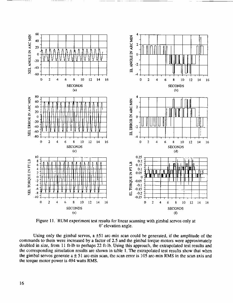
Figure 1 l. RUM experiment test results for linear scanning with gimbal servos only at0 ° elevation angle.
Using only the gimbal servos, a +51 arc-min scan could be generated, if the amplitude of the
commands to them were increased by a factor of 2.5 and the gimbal torque motors were approximately
doubled in size, from 11 ft-lb to perhaps 22 ft-lb. Using this approach, the extrapolated test results and
the corresponding simulation results are shown in table 1. The extrapolated test results show that whenthe gimbal servos generate a + 51 arc-min scan, the scan error is 105 arc-min RMS in the scan axis and
the torque motor power is 494 watts RMS.
16

Therefore,usingthe RUM's to helpgeneratea+51 arc-min linear scan at a 0 ° elevation angle
reduces the RMS error in the scan axis by a factor of 105 and reduces the total RMS power dissipated in
the torque motors by a factor of 494. The size of the gimbal torque motors can also be reduced, by a
factor of 5 or more. Their required peak torque can be reduced from about 22 ft-lb to about 4 ft-lb or
less. This means less gimbal motor mass, friction and stiction, cogging and ripple, and better resolution
in the torque commands. The reduced mass helps to offset the mass of the RUM devices. The other
changes have a positive effect on scan accuracy and power dissipation. Furthermore, the lower reaction
torques on the mounting base mean that the base can be less rigid and consequently less massive.
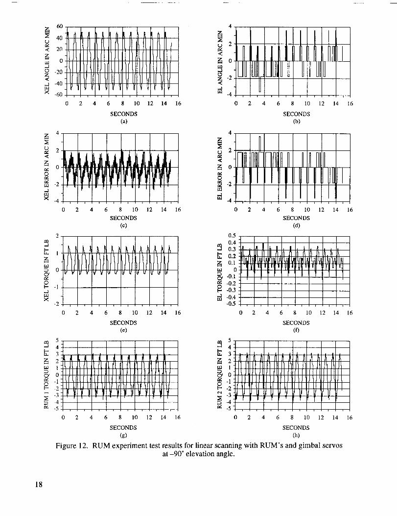
This same methodology was repeated at an elevation angle of -90 °. This is the worst orientation
for linear scanning with RUM's in one-g, because the gravity torque on them is a maximum. The results
at this orientation, scanning with and without RUM's, are shown in figures 12 and 13, respectively, and
are again summarized in table 1. At-90 °, a +51 arc-min scan was generated using both the RUM's andgimbal servos. Again the scan accuracy was 1 arc-min RMS in the scan axis and the motor power dissi-
pated in this orientation was now 29 watts RMS.
In this same orientation, a +51 arc-min linear scan was commanded using only the gimbal servos;
however, a +18 arc-min linear scan was actually generated. The scan accuracy was 42 arc-min RMS in
the scan axis and required a total torque motor power of 79 watts RMS. When the gimbal servocommands are increased by a factor of 2.5 and the gimbal torque motors are doubled in size, a +51 arc-
min linear scan can be generated. Except in this case, the scan accuracy is 105 arc-min RMS and the
total torque motor power dissipated is 494 watts RMS. These results were derived by extrapolation, as
before, and are identical to the extrapolated results at 0 ° elevation angle, as expected.
Thus, using the RUM's to help generate a +51 arc-min linear scan at a -90 ° elevation angle
reduces the RMS error in the scan axis by a factor of 105, reduces the total RMS power dissipated in the
torque motors by a factor of 17, and allows the size of the gimbal torque motors to be reduced by a fac-tor of 5 or more. The benefits from smaller gimbal motors were previously indicated. Note that these
improvements are at a 1 sec scan period.
With lower scan periods, or higher scan frequencies, the improvements are even greater when the
RUM's are used for linear scanning. Without the RUM's, each time the scan period is cut in half, the
cross-elevation torque motor needs to generate 4 times more torque and dissipate 16 times more power
to produce the same sized linear scan. This can be seen by differentiating equation (5) twice, substituting
this result into equation (4), and solving for T x to get
LW J J(19)
Therefore, when the scan period Tt, is divided by 2, the peak cross-elevation torque increases by a factor
of 4. From equations (18) and (19), it becomes apparent that reducing the scan period by a factor of 2
increases the power dissipated in the cross-elevation torque motor by a factor of 16.
On the other hand, when the RUM's are used for scanning, the peak motor torques, and conse-
quently the power dissipated in the motors, are virtually the same at any scan period. This is because the
RUM's rotate at a constant angular velocity to generate the scan motion. Furthermore, the
17
°60 4 I,I1 l'[I ItLI "_
o ;_ o
o-'.2o/llIl I_I_L/ILl, -_ IJl J UI JOlz I _ _-
[I IllIIIIt,If1Ji _ -_ - -,...a -40
_ Ill I[II_,_I_- _' V _ _X -60 , , , , , , , m -4
0 2 4 6 8 10 12 14 16 0 2 4 6 8 10 12 14
SECONDS SECONDS
(a) (b)
2
o=<- ,J,,i_,,I,L_IAL_,, _ 11I[ -111n I 11,... 0 . , ,' " _ 0
X I i , I i _ '-4 ,
0 2 4 6 8 10 12 14 16 0 2 4 6 8 10 12
SECONDS SECONDS
(c) (d)
0.5
m.j 0.4 A
iiii!II I(ll|r r II_ lip ]I rl r u _I
o' ',," v u ,,"_ v ,,, = -0.]. f I",," 0 t r i0["" _ -0.3,..3
m _ -0.4X m
..... -0.5 ........
0 2 4 6 8 10 12 14 16 0 2 4 6 8 10 12 14
SECONDS SECONDS
(e) (0
m 5
,[;'3 4t3 ! _ i! il _ _[_z 2 L .,,_
=m 111,. I t_ n rlIll, _ 1 _ 1' [[] Ill I1 Ill II tll 15ltl Jh 1tiJ_o, o • 11]1, l_h,, = o41 JU/t llltlltltll(llll(tlllltltll
_-° -2 ! I It ,t111t{ _1%tL_ -2
= -4J " " : .... ; } "3_r | r , 1' T 'r"" -5 , , , ' , . i , ,-,4 . . , , , , . ,
0 2 4 6 8 10 12 14 16 0 2 4 6 8 10 12 14
SECONDS SECONDS
(g) (h)
Figure 12. RUM experiment test results for linear scanning with RUM's and gimbal servos
at-90 ° elevation angle.
i
16
14 16
i
16
16
18

¢)e¢<
z;t.t]
_.]
Z<
ladX
60
4O
20
0
-20
-40
At f Af AJVJVd / VdV
-60
0 2
6O
40< _31¢llJIJ2O
_, o_14111¢11o _hllHIIa¢ -20
ua -40
ua -60
× -8ot I0 2
4
10
z 2_11fl="a oq_l !
-2q I/t_' -4!!! !,©
0 2
_ 2
<
_ o.1O
3-2
-4
4 6 8 10 12 14 16 0 2
SECONDS
(a)
f,lrl Itl)1tlllt)llf Itl)1 _ 2I¢llllJtt(lllO ftlllJtl¢l _ oIlllttl IlJllll JlltJlVI ©
1IlUIt11lJJ111/IIt tl l _ -2I I i I _-4
4 6 8 10 12 14 16 0 2
SECONDS
(c)
L I. I, i, I 0.2
II II /I Ill II II I_ II (l llJ [Z 0.1Jllll(_l 111)11111111 _i III_11/11_ IIll_llI]lll
i _ 0IIit1111 _llll_l II J o,
I1 (I I)11 [ IJ I[ Ill I11 11 1 _"
-0.2
6 8 10
SECONDS
(b)
4 6 8 10 12
SECONDS
(d)
I t, I II I "1"_II I II
4 6 8 10 12 14 16 0 2 4 6 8 10 12
SECONDS SECONDS
(e) (O
12 14 16
14 16
14 16
Figure 13. RUM experiment test results for linear scanning with gimbal servos only
at-90 ° elevation angle.
peak gravity torque on the RUM's and the peak friction torques in the RUM devices, gimbal motors and
bearings do not change with the scan period. Thus, the power required to scan with the RUM's is essen-tially independent of the scan period.
It is becoming obvious that scanning large payloads at high frequencies without RUM's can
require gimbal motors that are too big and consume too much power to be practical. For example, using
gimbal servos only to generate a +51 arc-min linear scan with a 0.25 sec period requires a
19

cross-elevation motor with about 350 ft-lb of peak torque. This motor would have to dissipate over
126 kilowatts of RMS power when scanning in either one-g or zero-g. When RUM's are used for the
same linear scan, gimbal motors with 4 ft-lb peak torque can be used and the total motor power would be
around 29 watts RMS or less in one-g and 1 watt RMS in zero-g.
Also, the amount of motor power required for scanning affects the mass of the electrical system
producing this power. To get an idea of this relationship between power and mass for space applications,
reference 10 describes the electrical power system for an Earth-orbiting spacecraft. The power genera-tion/storage system delivers about 1 kilowatt of usable power and has a 2,000 lb mass, which includes
the solar arrays, batteries and cables. As the power it must deliver goes up, so does its mass. Thus, there
is a practical limit to the power that the electrical system can produce for scanning.
VI. TEST RESULTS FOR CIRCULAR SCANNING
The same procedures and methodology used for testing and evaluating linear scanning, with and
without RUM's, were used for circular scanning. In this case, a 0 ° elevation angle is the worst orienta-
tion for circular scanning with RUM's in one-g; and a -90 ° elevation angle is the best orientation and
simulates circular scanning with RUM's in zero-g.
Figure 14 shows the actual steady state results from the RUM experiment for circular scanning
with the RUM's and gimbal servos. The nominal elevation angle is 0 ° and the scan period is 1 sec.Instead of plotting the cross-elevation and elevation angles versus time, they were plotted versus each
other, to better show the scan pattern generated. The results from figure 14 are summarized in table 2.
The results show a 55 arc-min radius circular scan was generated with scan errors of 4 arc-min RMS or
less in each axis. The total power dissipated in the four torque motors used for scanning was 32 wattsRMS.
For comparison, this same case was run with the computer simulation model of the RUM
experiment. These results are shown in figure 15 and are again summarized in table 2 by the numbers in
parentheses, just under those from the actual RUM experiment. The two results compare fairly well,since the RMS scan errors were within a factor of 2 of each other. Also, the actual power required by the
torque motors was 52 percent more than predicted by simulation, which means the RMS torques are just
23 percent larger. This difference is to be expected, since the computer simulation model is simplified in
some respects, as previously indicated.
This same circular scan was attempted in the actual RUM experiment using only gimbal servos.
These results are presented in figure 16 and are summarized in table 2. The scan never reaches a steadystate condition, because of motion in the elevation axis. The radius of the scan about this motion is
approximately 18 arc-min, the scan errors are 42 arc-min RMS or more in each axis, and the powerdissipated in the gimbal torque motors is 147 watts RMS. The simulation results for this case are also
summarized in table 2 and follow the same pattern previously observed when comparing the simulationresults with the actual test results.
Again, if the magnitude of the gimbal servo commands were increased by a factor of 2.5 and the
gimbal torque motors were doubled in size, then a circular scan with a 51 arc-min radius could be
generated using only the gimbal servos, although its center may still wander. By extrapolation, the pre-dicted results for this case are summarized in table 2. The scan error is now 105 arc-min RMS or more in
each axis and the total torque motor power is 919 watts RMS. Therefore, using the RUM's to help
20

60
i )_,#"
-60 1 , '
-80 -60 -40 -20 0 20 40 60 80
XEL ANGLE IN ARC MIN
(a)
20
i_ oI.I.1
,.d-20
_ -40.1
m
4"I Ii II ill i_i I, ,,.1J ill _2q_rll fll,Pt,!.lll#lllf !I_M _I_
Oq.!!l' ',[lllrl,llll ilJlI' 'I.:2ltll i III[IIIILJ]f IIIIo _4.!.1{! II I_ IFII II _i ,r tf ir
6 _ up IP hi I_ Ir IV t,r I il II]8 i |rNrl'' Tu1ol , r, 1, ] r,
0 2 4 6 10 12 14 16
SECONDS
(c)4
,_ 32
m 0
.I -3
_4
g
4 dl IL rll I i l I i.i A Illlil_i _ II I ,1:liil ILIi I11"" 23tpl_I ,,li'lrletridrqtllilqi"io]'
< l/ill i ,lillJlIll_llil[ Jlrl I
z, _ I1]td Irur,,lenrl,1!! Itl!J
0"" -13|LllPli)ilnlkltllllilil, , !_" "'"jiii II
2 IdlJlll llllIlfqll III,i,, [ 11 iJ II Ii I'JI,J Ii I li I J ii Iua r[l' II II ir II IU l' I :i Ir
-4 " " J " 1
,-.i l" ,l l - -_56X . ! !
0 2 4 6 8 10 12 14 16
SECONDS
(b)1
0.6__ 11_I I_ Ilfl I1,,I
o.4oqV III I IIII UII II,,, -o.241 TI rll III T - ""
,j -0.6
-0.8-1 , , , , , ,
0 2 4 6 8 I0 12 14 16
SECONDS
(d)
4
Z 2 _ I! rl r ' " I
iitJo' 0 ......
_ -1 ......
:E -3 .......
,.v -4 , , I , , ,
0 2 4 6 8 10 12 14 16
SECONDS
(f)
5_ 4
3
21
O' 0e_ -1
_ -3
_.5
_ A _ n fin 5 _
/I/I/t),,<,,JrJl!!; ;,i ;; ; ;; :;
If 1 1 : II I I I
u l u l
0 2 4 6 8
l Ill
n I _ l ) ] i I
•] firI
I ! i
10 12 14 16
SECONDS
(e)
ifliiiirill irl Ilk
;ill 111Illtll illLII Ll% 71l!!!!!
0 2 4 6
II_,'lli_vl ,{I I
lllii'; l?Ir IIIllll..lll it; if II II Ii ii 11i "
ii il tl _i !j lj i i ii
! '1 r i !, ' ?,!i1, 'I -I, I8 10 12 14 16
SECONDS
(g)
Figure 14. RUM experiment test results for circular scanning with RUM's and gimbal servos at0° elevation angle.
21
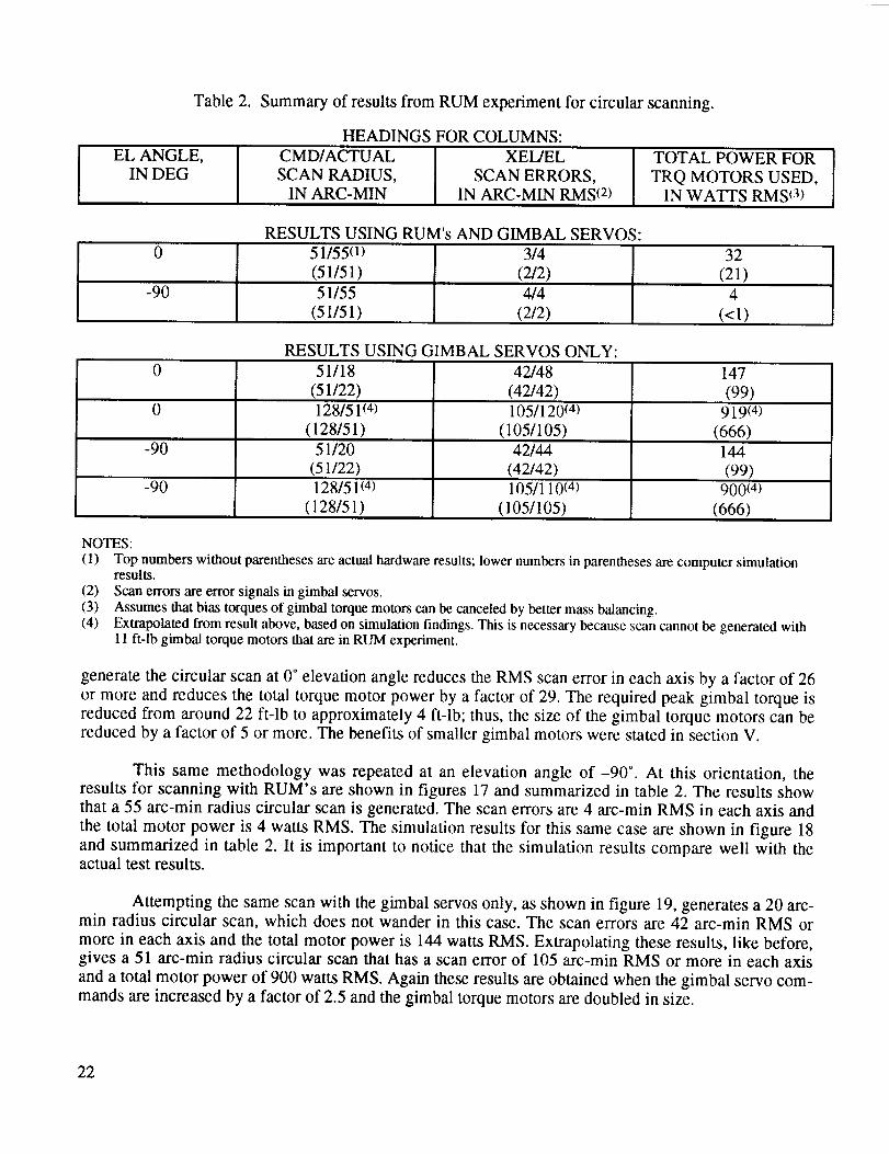
Table 2. Summary of results from RUM experiment for circular scanning.
EL ANGLE,IN DEG
HEADINGS FOR COLUMNS:
CMD/ACTUAL I XEL/ELSCAN RADIUS, SCAN ERRORS,
IN ARC-MIN IN ARC-MIN RMS (2)
TOTAL POWER FOR
TRQ MOTORS USED,
IN WATTS RMS(3)
RESULTS USING RUM's AND GIMBAL SERVOS:
0 51/55(1)
(51/51)
-90 51/55
(51/51)
3/4
(2/2)
4/4
(2/2)
32
(21)
4
(<1)
RESULTS USING GIMBAL SERVOS ONLY:
0 51/18 42/48 147
(51/22) (42/42) (99)0 128/51 (4) 105/120(4) 919(4)
(128/51) (105/105) (666)-90 51/20 42/44 144
(51/22) (42/42) (99)-90 128/51 (4) 105/110 (4) 900(4)
(128/51) (105/105) (666)
NOTES:
(1) Top numbers without parentheses are actual hardware results; lower numbers in parentheses are computer simulationresults.
(2) Scan errors are error signals in gimbal servos.
(3) Assumes that bias torques of gimbal torque motors can be canceled by better mass balancing.(4) Extrapolated from result above, based on simulation findings. This is necessary because scan cannot be generated with
I 1 ft-lb gimbal torque motors that are in RUM experiment.
generate the circular scan at 0 ° elevation angle reduces the RMS scan error in each axis by a factor of 26
or more and reduces the total torque motor power by a factor of 29. The required peak gimbal torque is
reduced from around 22 ft-lb to approximately 4 ft-lb; thus, the size of the gimbal torque motors can bereduced by a factor of 5 or more. The benefits of smaller gimbal motors were stated in section V.
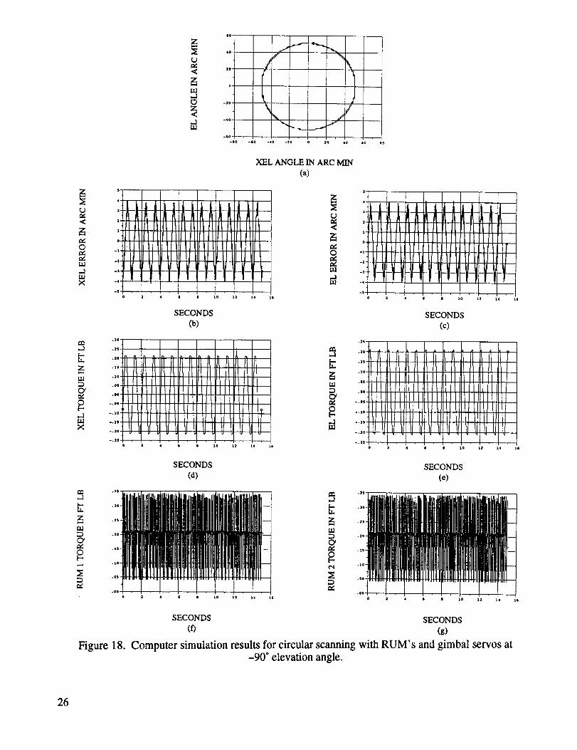
This same methodology was repeated at an elevation angle of-90 ° . At this orientation, theresults for scanning with RUM's are shown in figures 17 and summarized in table 2. The results show
that a 55 arc-min radius circular scan is generated. The scan errors are 4 arc-min RMS in each axis and
the total motor power is 4 watts RMS. The simulation results for this same case are shown in figure 18
and summarized in table 2. It is important to notice that the simulation results compare well with theactual test results.
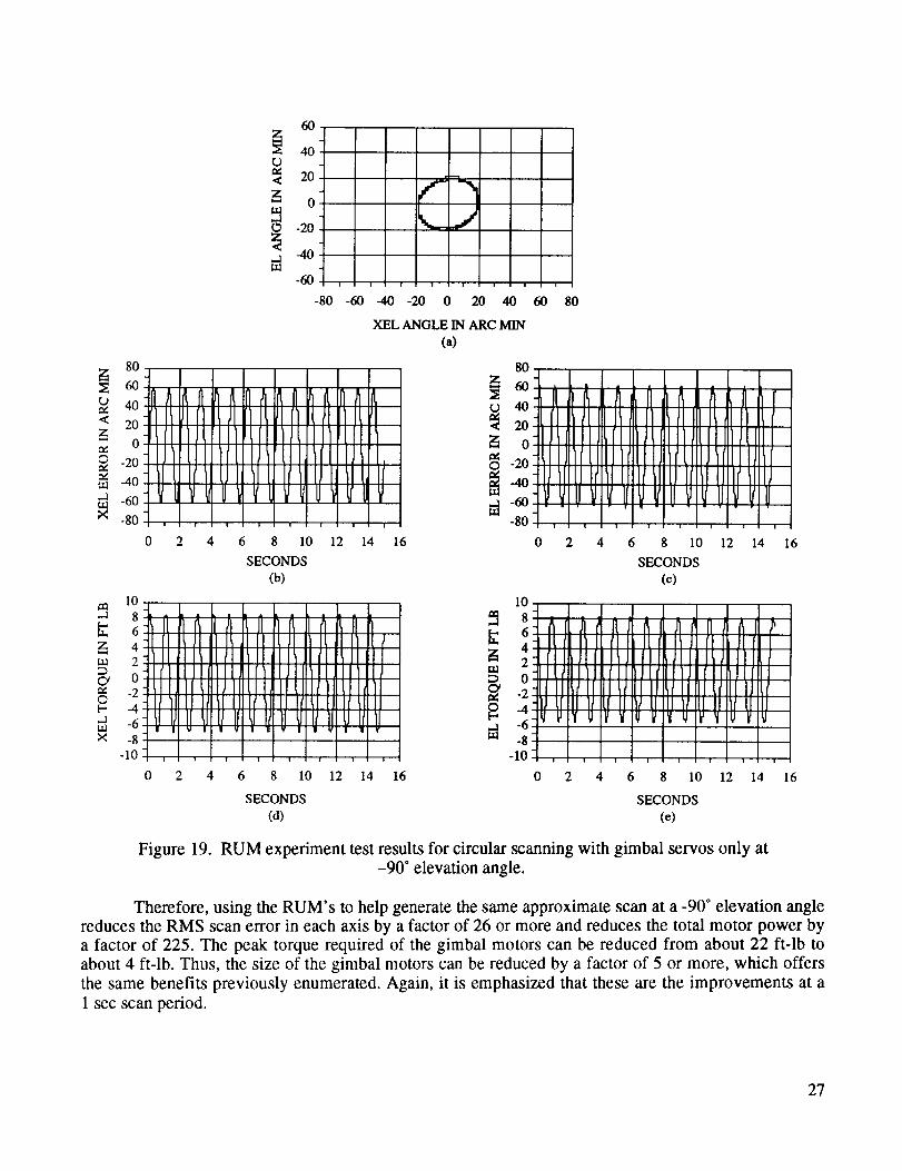
Attempting the same scan with the gimbal servos only, as shown in figure 19, generates a 20 arc-min radius circular scan, which does not wander in this case. The scan errors are 42 arc-min RMS or
more in each axis and the total motor power is 144 watts RMS. Extrapolating these results, like before,gives a 51 arc-min radius circular scan that has a scan error of 105 arc-min RMS or more in each axis
and a total motor power of 900 watts RMS. Again these results are obtained when the gimbal servo com-
mands are increased by a factor of 2.5 and the gimbal torque motors are doubled in size.
22

,d
,.J
+o
,io
2O
-2o
-4o
-60-BO 0
XEL ANGLE IN ARC MIN
(a)
c_<
t_©,.¢
..3
><
.2
z
CY
©[.-.=d
×
o, 2
.... Ifu
o
SECONDS
(b)
olo o]o olo olo oii ,LP1111IIItl I!Iit I/Itl 1
/
I,,lIt,,,I/Ill]till /IIIIllll
tlllllli 111tlI ltttiJl II I ltll
¢ s e zo za 1,1
<
©
M
1
i.[t +I11It It It II It i111It LL[LLLE_°[IItPIItI/II /llllltlillHltl/_rip tl tl II till It LLLLLLLLLLLLtLL_
+ ill II II IJ II II il/I LLiJ__I_tI__IZ_
SECONDS
(c)
z+ o 2 4 i • 1o 12 ;4 1_
SECONDS SECONDS
(d) (e)
t_..3
,vz
,.¢
e¢
lit /lltt
o _ • • e xo la 14 I_ o 2 * 4; • I0 14
SECONDS SECONDS(f) (g)
Figure 15. Computer simulation results for circular scanning with RUM's and gimbal servos at0 ° elevation angle.
23

r..),.¢<
,.¢©,.¢e¢Lt_.-1Lt_X
et_...J
zt.kl
G_r¢©[--..dLidX
60
t..)
2oo
gJ-20
.1m -60
-80 -60 -40 -20 0 20 40
XEL ANGLE IN ARC MIN
80
60 I I .I .1_ 1. I. I_40 ] nl_ fllJ_hilt _lt%fll/_filflJ_lt_
o /ttll IIV11111t¢1111I/VIIIU-2o IIPt[II I11_IIIVIIIII?tl II1VL-40 1(_1IJ1[II IP1[klIt )1lJIr II tl /-6o V_II__ IdUt/IJ I/_ U_ t/I,I-8o I I I I I I I
0 2 4 6 8 10 12 14 16
SECONDS
(b)
60 80
(a)
100q I I I I • _ _ I_ ^ k I8°-t I I L ,,,I_tlr_)l[lI[lt I6o-.i _ h _ _ 111_11llltlllLJIIltll I_ tl Jl ll r_ll llllNllllltlllt_ll[ Io-llllll/lJll_ll/lJIIIllll_fllllfllJ I
.2o.111_Alllittll_l II1_1I1111lJltf _JIII I© .-4o-I_llllIflJIIItlll/llllt el_' _ t/ ld _'
-6o-IIl_llllllllftlll/ _ ' I I I I
_t_,_'','-8o .... Im -100
0 2 4 6 8 10 12 14 16
SECONDS
(c)10 10 -
II II II _ 4 II II ft II Jl II i'llI1 I[ I Ih It4-11 II II II fl II it II
,,ll , itlti' !l o: '""IIl_l!/ll[I I IIl_/Ifll t)lt[lll_,.2.1_f1 till IlJl _ -2:.4-t I11 II tt il II I ,/II II II _ -4- tJllf IIIU li II tllll IJ[(III/) LfI_
.6-1 _' I lfl I, I111U II ,/I(l II _ _6:1,1 UIV VIUY _1ol_'uru_,u v-_oq I I I _ --10
0 2 4 6 8 10 12 14 16 0 2 4 6 8 10 12 14
SECONDS SECONDS
(d) (e)
16
Figure 16. RUM experiment test results for circular scanning with gimbal servos only at0 ° elevation angle.
24

cje_<
e¢©
r_Ua.2
X
60
Z
40ro,"," 2O<
o
-20
_ -40.1u.l -60
" Xf
/¢
J
\ .,/i !
-80 -60 -40 -20 0 20 40
)(EL ANGLE IN ARC MIN
(a)
8
4 .7
2 I1II' tiI[ rllr "" " ':: ; .'::
o J_'ii,iiWiiii_:.2_/L [IHJrlillll .... : !::
.4-I',!"_l'iIPiiii't'-8 , I , I - ' • ' " " '
0 2 4 6 8 10 12 14
SECONDS
(b)
I
II
I
0 2 4 6 8 10 12 14
SECONDS
(o)
!
60 80
i I
+,r'L'IT.r#plIrl! r!!qr rrg._!r ' r_ri l
i I
i I
i ! ] i i I i .
0 2 4 6 8 10
SECONDS
(0
1,5 •
-1
z 1:
CY
0 0.5t--.,.duaX
0,
1,.a 0.8
0.6
Z 0.4ua 0.2
O' 0-0.2-0.4
_7 -0.6-0.8
"" -1
JI
I
16
i
16
10
4 "Ilk | [ L 1_
2-U1Fllll tlo_ldllllJ_
. I II& /t a JIl_ It #1kill ,LII1 I1 r_ It Yl r' [_ II Ira 12I_II'Ll' LII]I I I1UIIlU'
,_ .2l'lJ IMtr I111o -4|_11111t1_1
-6 + IJ _r if LJII
-sliP'iT l_l"'-]o , 1 _ I0 2 4
4
32
m 0
_-1_-2.I -3
-4
I0.8
i 0.6
0.4
0.2
0-0.2
-0.4
_ -0.6
_ -0.8_ -1
II_I Ittl lJ_rtlil _Jlt5111LPIU If il IM11
I I l
6 8 10 12 14
SECONDS
(c)
+iinii, ii ,I,i
0 2 4 6 8 10 12
SECONDS
(e)
ii
i
16
i
14 16
I,IIj ,t,t,at.
'.:',i."_',+.IfP_'lr! iT'
i i !
0 2 4 6
i t
IL_.,i,ii],_
ll Illlgl IIm' IFP !1!11
i i
i i
i t
i . i .I I i i
12 14 16 8 10 12 14 16
SECONDS
(g)
Figure 17. RUM experiment test results for circular scanning with RUM's and gimbal servos at-90 ° elevation angle.
25
-<
,v©r¢r¢t.o.d
r_J
z
r_..d
z
c¢
Figure 18.
<
mM
,..1LII
6O
41).
2O-
O"
1- ]O, '
Io
-6o .]
-co
'_.. j
-60 -¢0 -20 0 20 ¢0 to eO
XEL ANGLE IN ARC MIN
(a)
SECONDS
(b)
O
.]
Ill
SECONDS
(ct)
iiiil llillillll ]illltlitlllllt• qltl W._ll qlll_lill I plltll I _ OS
.,,f. T [ "1..... _ 2t:2""'f"Jo _ 4 • II lO I1 1_ " 1_ °°'o 2
SECONDS
(e)
• e 1o 11 l* 15
SECONDS SECONDS
(0 (g)
Computer simulation results for circular scanning with RUM's and gimbal servos at-90 ° elevation angle.
26
80
rO 40
< 20
_ o
© -20
-40
"_ -60
-80
m 108
,[7 6
z 4m 2
0"¢ -2©t-., -4,.d -6
-10
60
_ 40o
20
_ om.10 -20
_ -40
-60
-80 -60 -40
-t(1It tJlfl II 11l1 It +1fl It ill-I_flllJ[ [I IIPLfllltlll Ill4IJ/ttl IJtltl t;Irtl IJtfll-III UI( II U li II U II tl IJII-I I,' II _ VlO'd_ I.IV _ U'_4, , ,, .I.10 2 4 6 8 10 12
SECONDS
(b)
-20 0 20 40
XEL ANGLE IN ARC MIN
(a)
l(
I. L
I11%1111IIIlfllll
iJill IIII)llll ll Itlll II_111_11II I1I V II I Y
I
!
14 16
L .L L L
II ItII II It II ¢1I_ II IIflllJllllllllllllI IAll [llltllltl IJll
II IIIII I(1_1tllll _lllJkl Iit I[ tJIIt III U Itl II
' "l"'l' ']' '"i
0
d
60 80
_-L L,I l [ / L,L I
=o-I1fl I_II illi_/11[I It II III I__lII It l Io-IIJ_fllIIJl_flIll/till I]11(1111]ltillI I
_2o-I(IIlilILIIIlltlllIlltttlllJl¢il//tltfI-4o-illtlILIItlll IIII/t1111IIl/I Jill(/111_I_6o-I_1VIII_111/itl_l/lit VII/1]IVI/ill I-,ot, , ,' ",l, ,l,l, I
0 2 4 6 8 10 12 14 16
SECONDS
(¢)10
8642
no0
-2
_ _8
-10
q_] / J J 1.
-1 It 11 II II II Ik I1 IkJI [I I,-! (I Ir_JI II I_ Jl l; 11II I1(I-tll[lllllll(llnl Irlllflll4lllll_,lllll_illl ,, ,tllllJt/-I1JUIII It Ill II Ill It I II Ill II //
0 2 4 6 8 10 12 14 16 0 2 4 6 8 10 12 14 16
SECONDS SECONDS
(d) (e)
Figure 19. RUM experiment test results for circular scanning with gimbal servos only at-90 ° elevation angle.
Therefore, using the RUM's to help generate the same approximate scan at a -90 ° elevation anglereduces the RMS scan error in each axis by a factor of 26 or more and reduces the total motor power bya factor of 225. The peak torque required of the gimbal motors can be reduced from about 22 ft-lb toabout 4 ft-lb. Thus, the size of the gimbal motors can be reduced by a factor of 5 or more, which offersthe same benefits previously enumerated. Again, it is emphasized that these are the improvements at a
1 sec scan period.
27
At smaller scan periods, the improvements are even greater when the RUM's are used for circu-
lar scanning. Without the RUM's, each time the scan period is divided by 2, both the cross-elevation and
the elevation motors need to generate 4 times more torque and dissipate 16 times more power to produce
the same sized circular scan. These changes can be proven by the same argument used for linearscanning. Only now, the argument applies to both the cross-elevation and the elevation axes. Thus, each
time the scan period is decreased by a factor of 2, the power dissipated in the gimbal motors increases bya factor of 16, when only the gimbal servos are used for circular scanning. Using the same argument as
before, the power required to circular scan with RUM's is virtually independent of the scan period.
Again, it is apparent that scanning large payloads at high frequencies without RUM's can require
huge gimbal motors that consume too much power to be practical. For example, using gimbal servos
only to generate a 51 arc-min radius circular scan with a 0.25 sec period requires gimbal motors with
about 350 ft-lb of peak torque. These motors would have to dissipate a total power that exceeds 230 kW
of RMS power when scanning in either one-g or zero-g. When RUM's are used to generate the same
circular scan, gimbal motors with 4 ft-lb peak torque can be used and the total motor power would be
around 32 watts RMS or less in one-g and 1 watt RMS in zero-g.
VII. CONCLUSIONS AND COMMENTS
This experiment has proven a new technology for scanning space-based, balloon-borne, and
ground-based gimbaled payloads, as well as free-flying spacecraft. The test results prove that RUM
devices can be used to generate accurate linear and circular scans for gimbaled payloads in zero-g and
one-g, with very little power. An auxiliary control system is needed to center the scan, and produce somecomplementary motion when raster scanning. Also, extending the results presented here to free-flying
spacecraft is straightforward.
Since the results from the simplified computer simulation model of the RUM experiment agreed
fairly well with the results from the actual RUM experiment, the basic theory of scanning with RUM
devices is verified. This allows the results presented here to be scaled for larger and smaller payloads
scanning at higher and lower frequencies.
Basically, the RUM experiment showed that a pair of RUM's with 5 lb masses on 6 inch lever
arms can generate a +51 arc-min linear scan with a 5 ft long, 250 lb gimbaled payload. Generating this
scan without RUM's increases the required motor power by a factor of 17 to 494 in one-g and a factor of
494 in zero-g, at a 1 sec scan period. Furthermore, the size of the gimbal motor in the scan axis increasesby a factor of 5.
When the RUM's are used and the scan period is changed, the total motor power and the size of
the gimbal motors are unaffected. However, without the RUM's, each time the scan period is reduced by
a factor of 2, the motor power increases by an additional factor of 16 and the gimbal motor in the scan
axis increases by an additional factor of 4. The increased motor power adversely affects the mass of the
electrical power system and a larger gimbal motor requires a stiffer and more massive base structure toreact against.
Also, the RUM experiment showed that the same identical RUM devices, mounted for circular
scanning, can generate a 55 arc-min radius circular scan with the same gimbaled payload. Generatingthis scan without the RUM's increases the required motor power by a factor of 29 to 225 in one-g and a
28

factor of 225 in zero-g,at a 1 secscanperiod. In this case,both gimbal motorshaveto be aboutfivetimeslarger.
WhentheRUM's areusedandthescanperiodis changed,thetotal motor powerandthesizeofthegimbalmotorsareunaffected.However,withouttheRUM's, eachtime thescanperiod is reducedbyafactorof 2, themotorpower increasesby anadditionalfactorof 16andthesizeof bothgimbal motorsincreasesby afactor of 4.
Furthermore,thegimbalmotorsaremorelikely to wearoutsoonerwhentheymustcontinuouslyaccelerateanddeceleratethepayload.Theincreasedpowerdissipationalsogeneratesmoreinternalheat,which affectsperformanceandshortenslife expectancy.Whenthe RUM's areused,thegimbal motorswork very little andtheRUM's rotateata constantvelocity, soall of themotorsshouldhavea longlife-time.
This experimentprovesthatit is now feasibleto accuratelyandreliably scanlargepayloadsathigh frequencieswith significantly lesspowerandsignificantly lessmass,when RUM's generatethebasicscanmotion.Furthermore,sincescanningwith RUM's is not foundedon torquing againsta basestructure,it alsomeansthat largepayloadscanscanat high frequenciesin placeswherethis wasonceimpossible.For example,considerballoon-bornepayloadsor free-flyingspacecraft.
As aresult of this experiment,RUM's arenow a proventechnologythat haveknown applica-tions in spaceandhavepotentialapplicationsin defense,industry,andmedicine.For example,RUM'smayhavepotentialapplicationin military fire controlsystemsfor scanningguns.In industry, theyhavepotentialapplicationsin sprayingwaterfor fighting forest fires or sprayingliquid fertilizers and pesti-cidesin openfields.RUM's requiresolittle powerthatbatteriesor solarcellscouldbeusedasanenergysourcein remote locations.Also, RUM's could be usedin spraypainting with a fragile robot arm,becausethey generatevirtually no reactiontorqueson thearm. In medicine,they maybeusedfor pre-ciselyscanningmedicaldeviceswithconsiderablylesspower.
29
REFERENCES
, Nein, M.E., and Nicaise, P.D.: "Experiment Pointing Subsystems (EPS) Requirements for the
Spacelab Missions." NASA TM X-64978, NASA Marshall Space Flight Center, AL, December1975.
2. "The GRID on a Balloon Definition Study Report." NASA Goddard Space Flight Center,Greenbelt, MD, June 14, 1989.
. "Space Telescope Moving Target and Scan Pointing Capability Error Budget, ST/SE-24, SectionH, Part 4." LMSC/FO61415, Lockheed Missiles and Space Company, Sunnyvale, CA, October 21,1985.
. Polites, M.E.: "Rotating-Unbalanced-Mass Devices for Scanning Balloon-Borne Experiments,
Free-Flying Spacecraft, and Space Shuttle/Space Station Experiments." NASA TP-3030, NASA
Marshall Space Flight Center, AL, June 1990.
. Polites, M.E.: "New Method for Scanning Spacecraft and Balloon-Borne/Space-Based Experi-
ments." Journal of Guidance, Control and Dynamics, vol. 14, No. 3, May-June 1991, pp. 548-553.
. Polites, M.E.: "Rotating-Unbalanced-Mass Devices and Methods for Scanning Balloon-Borne-
Experiments, Free-Flying Spacecraft, and Space Shuttle/Space Station Attached Experiments,"
U.S. Patent No. 5,129,600, National Aeronautics and Space Administration, Washington, DC, July14, 1992.
. Polites, M.E. and Alhorn D.C.: "Suspension System for Gimbal Supported Scanning Payloads,"
U.S. Patent Application No. 08/123629, National Aeronautics and Space Administration,Washington, DC, September 15, 1993.
. Lightsey, W.D., Alhorn, D.C., and Polites, M.E.: "Definition and Design of an Experiment to Test
Raster Scanning With Rotating Unbalanced-Mass Devices on Gimballed Payloads." NASA TP-3249, NASA Marshall Space Flight Center, AL, June 1992.
. Polites, M.E. and Alhorn, D.C.: "Reconfiguring the RUM Experiment to Test Circular Scanning
With Rotating Unbalanced-Mass Devices on Gimballed Payloads." NASA-TP-3282, NASA
Marshall Space Flight Center, AL, September 1992.
10. "SIRTF at Higher Altitudes," internal document prepared by the Program Development Direc-torate, NASA Marshall Space Flight Center, AL, December 1987.
U.S. GOVERNMENT PRINTING OFFICE 1994--533-108/00016
30

Form Approved
REPORT DOCUMENTATION PAGE OMBNo. o7o4-oiee
Publicrepotting burden for thiscollection of information is estimated to average 1hour per response, includingthe time for reviewing instructions,searching exist ncJdata sources.gathering and maintaining the data needed, andcompleting and reviewing the collectionof information. Sendcomments regarding th s burden est mate or anyother aspect of thiscollectionof information, includingsuggestionsfor reducingthis burden, to Washington HeadquartersServices,Directorate for Information Operations and Reports, ! 215 JeffersonDavis Highway,Suite 1204. Arlington, VA 22202-4302, and to the Office of Management and Budget,Paperwork ReductionProject(0704-0188),Washington, DC 20503.
1. AGENCY USE ONLY (Leave blank) 2. REPORT DATE 3. REPORT TYPE AND DATES COVERED
January 1994 Technical Paper
4. TITLE AND SUBTITLE 5. FUNDING NUMBERS
Results of a Laboratory Experiment That Tests Rotating Unbalanced-
Mass Devices for Scanning Gimbaled Payloads and Free-FlyingSpacecraft (CDDF Final Report No. 92-02_
6. AUTHOR(S)
D.C. Alhorn and M.E. Polites
7. PENFORMING ORGANIZATION NAME(S) AND ADDRESS(ES) 8. PERFORMING ORGANIZATIONREPORT NUMBER
George C. Marshall Space Flight Center
Marshall Space Flight Center, Alabama 35812 M-741
9. SPONSORING / MONITORING AGENCY NAME(S) AND ADORESS(ES) 10. SPONSORING / MONITORINGAGENCY REPORT NUMBER
National Aeronautics and Space AdministrationNASA TP-3458
Washington, DC 20546
11. SUPPLEMENTARY NOTES
Prepared by Astrionics Laboratory and the Structures and Dynamics Laboratory, Science and Engineer-ing Directorate
1Za. DISTRIBUTION / AVAILABILITY STATEMENT
Unclassifted--Unlimited
Subject Category: 31
12b. DISTRIBUTION CODE
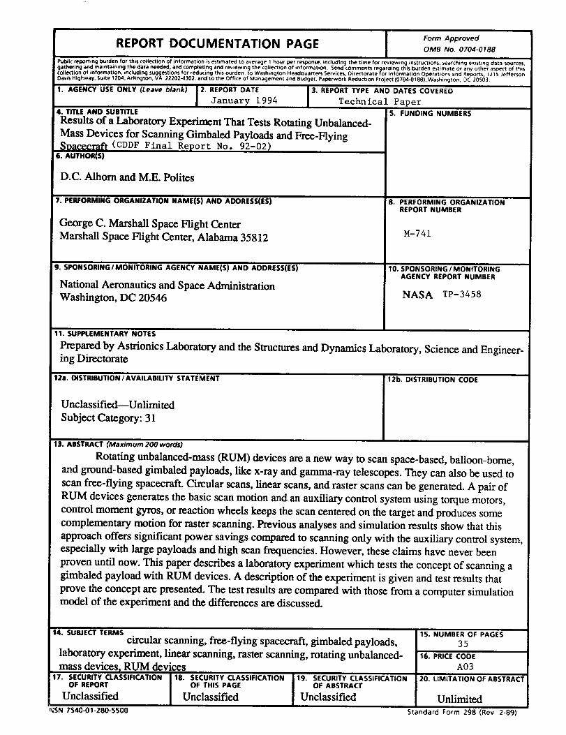
13. ABSTRACT (Maximum 200 words)
Rotating unbalanced-mass (RUM) devices are a new way to scan space-based, balloon-borne,
and ground-based gimbaled payloads, like x-ray and gamma-ray telescopes. They can also be used to
scan free-flying spacecraft. Circular scans, linear scans, and raster scans can be generated. A pair of
RUM devices generates the basic scan motion and an auxiliary control system using torque motors,
control moment gyros, or reaction wheels keeps the scan centered on the target and produces some
complementary motion for raster scanning. Previous analyses and simulation results show that this
approach offers significant power savings compared to scanning only with the auxiliary control system,especially with large payloads and high scan frequencies. However, these claims have never been
proven until now. This paper describes a laboratory experiment which tests the concept of scanning a
gimbaled payload with RUM devices. A description of the experiment is given and test results that
prove the concept are presented. The test results are compared with those from a computer simulationmodel of the experiment and the differences are discussed.
14. SUBJECT TERMS
circular scanning, free-flying spacecraft, gimbaled payloads,
laboratory experiment, linear scanning, raster scanning, rotating unbalanced-
mass devices_ RUM devices!17. SECURITY CLASSIFICATION 18. SECURITY CLASSIFICATION 19. SECURITY CLASSIFICATION
OF REPORT OF THIS PAGE OF ABSTRACT
Unclassified Unclassified Unclassified
_SN 7540-01-280-5500
15. NUMBER OF PAGES
3516. PRICE CODE
A0320. LIMITATION OF ABSTRACT
Unlimited
Standard Form 298 (Rev 2-89)