responses to the tohoku–pacific ocean earthquake and tsunami
TRANSCRIPT
Responses to the Tohoku–Pacific Ocean Earthquake and
Tsunami at the Onagawa Nuclear Power Station and
Tokai No.2 Power Station (report)
August 2013
Japan Nuclear Safety Institute
i
Table of Contents
1 Preface ................................................................................................................................................................ 1 2 Overview of the Tohoku–Pacific Ocean Earthquake and Tsunami .................................................................... 2
2.1 Overview of the earthquake and tsunami..................................................................................................... 2 3 3 Overview of the Onagawa Nuclear Power Station .......................................................................................... 6
3.1 Overall layout .............................................................................................................................................. 6 3.2 System configuration ................................................................................................................................... 7 3.3 Power source system.................................................................................................................................... 9
4 Damage caused by the earthquake and tsunami at the Onagawa Nuclear Power Station .................................11 4.1 Observation results at the Onagawa Nuclear Power Station .......................................................................11 4.2 Damage and impact from the earthquake .................................................................................................. 14 4.3 Damage and impact from tsunami ............................................................................................................. 16
5 Responses to the earthquake disaster at the Onagawa Nuclear Power Station ................................................. 19 5.1 Overview of responses right after the earthquake and tsunami for recovery and cold shutdown .............. 19 5.2 Situation of the earthquake disaster responses........................................................................................... 19
5.2.1 Immediately after the earthquake occurred ....................................................................................... 19 5.2.2 Immediately after tsunami arrived .................................................................................................... 21 5.2.3 Measures for recovery after tsunami arrived ..................................................................................... 22
6 Lessons learned from the earthquake disaster responses at the Onagawa Nuclear Power Station ................... 29 6.1 Organization, management, communication ............................................................................................. 29 6.2 Preparedness (system, manual, training) ................................................................................................... 29 6.3 Initial responses in the event of the earthquake ......................................................................................... 30 6.4 Additional measures .................................................................................................................................. 30
7 Overview of the Tokai No.2 Power Station ...................................................................................................... 31 7.1 Overall layout ............................................................................................................................................ 31 7.2 System configuration ................................................................................................................................. 32 7.3 Power source system.................................................................................................................................. 34
8 Damage caused by the earthquake and tsunami at the Tokai Dai-ni Power Station ......................................... 35 8.1 Observation results at the Tokai No.2 Power Station ................................................................................ 35 8.2 Damage and impact from the earthquake .................................................................................................. 36 8.3 Damage caused by tsunami ....................................................................................................................... 36
9 Responses to the earthquake disaster at the Tokai No.2 Power Station ........................................................... 38 9.1 Overview of responses right after the earthquake and tsunami for recovery and cold shutdown .............. 38 9.2 Situation of the earthquake disaster responses........................................................................................... 38
9.2.1 Immediately after the earthquake occurred ....................................................................................... 38 9.2.2 Immediately after the tsunami arrived .............................................................................................. 40 9.2.3 Plant responses after the tsunami arrived at the plant ....................................................................... 40
10 Lessons learned from earthquake disaster responses at the Tokai No.2 Nuclear Power Station ...................... 44 10.1 Organization, management, communication ............................................................................................. 44

ii
10.2 Preparedness (system, manual, training) ................................................................................................... 44 10.3 Initial responses in the event of an earthquake .......................................................................................... 45 10.4 Additional measures .................................................................................................................................. 45
11 Conclusion ....................................................................................................................................................... 46
1
1 Preface
With the cooperation from electric power companies and plant manufacturers, the Japan Nuclear Technology Institute, the predecessor of the Japan Nuclear Safety Institute, summarized lessons learned concerning the Tohoku–Pacific Ocean Earthquake and Tsunami-induced accident at the Fukushima Dai-ichi Nuclear Power Station run by the Tokyo Electric Power Company, Inc. (TEPCO). It then prepared and published a report in October 2011. This report summarizes 80 items mainly consisting of hardware measures to prevent accidents
and mitigate their consequences, and strongly recommends that an additional 23 items of measures are implemented since they are considered to be important in terms of defense-in-depth. These measures have been implemented as necessary depending on the systems and conditions of each company and almost all items have already been implemented or their implementation is under consideration. Moreover, the Fukushima Dai-ni Nuclear Power Station run by TEPCO, Onagawa Nuclear Power Station, which in turn is run by the Tohoku-Electric Power Co., Inc., and Tokai No.2 Power Station, which is run by
The Japan Atomic Power Company could have prevented the nuclear disaster and shut down the plant safely in the face of impacts caused by the earthquake and tsunami. With support from TEPCO, the Japan Nuclear Safety Institute performed an analysis on the earthquake disaster responses at the Fukushima Dai-ni Nuclear Power Station, which sustained relatively extensive damage among these stations, in terms of human factors and organizations. The Institute extracted lessons learned mainly from a software aspect, and developed and published the report in December 2012.
These measures are not like those that will be completed once implementation has been done, but more like measures that should be improved continuously through exercises and the like. The above two reports are available from the website of the Japan Nuclear Safety Institute; please have a read through them since they have created momentum to prepare this report. With the objective of preserving the records of the earthquake disaster responses at the remaining two nuclear power stations, Onagawa Nuclear Power Station and Tokai No.2 Power Station, a review team was
established within the Japan Nuclear Safety Institute. The team consolidated the earthquake disaster responses at each power station and summarized the lessons learned, in cooperation with Tohoku-Electric Power Co., Inc. and The Japan Atomic Power Company. At the Onagawa Nuclear Power Station, a site elevation was secured that far exceeded the anticipated tsunami height, as a conservative approach when determining the site elevation during construction. Therefore, the main body of the plant received little damage from the tsunami, enabling it to have the accident situation
settle down. In addition, construction works to strengthen watertightness as measures against tsunami were underway at the Tokai No.2 when the earthquake occurred. Thus, a loss of all seawater pump functions could be avoided and this led to the accident situation settling down though there was a little damage in the area where construction works were unfinished. It is advisable to consider the way the organization is managed to clarify why these power stations took such measures and TEPCO did not. At this time, this report summarizes the responses at both power stations during the accident and extracts the
lessons learned, and the Institute expects this report to be utilized as a reference when each company addresses safety enhancement.
2
2 Overview of the Tohoku–Pacific Ocean Earthquake and Tsunami
2.1 Overview of the earthquake and tsunami
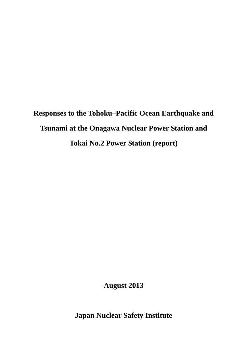
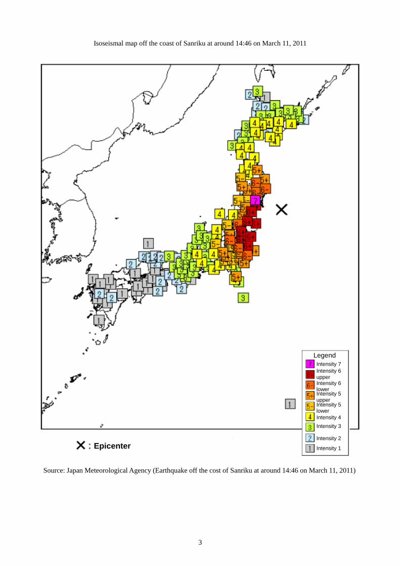
The Tohoku–Pacific Ocean Earthquake occurred at 14:46 on March 11, 2011 and was the biggest earthquake on record in Japan; a main shock and maximum seismic intensity of 7 was observed in
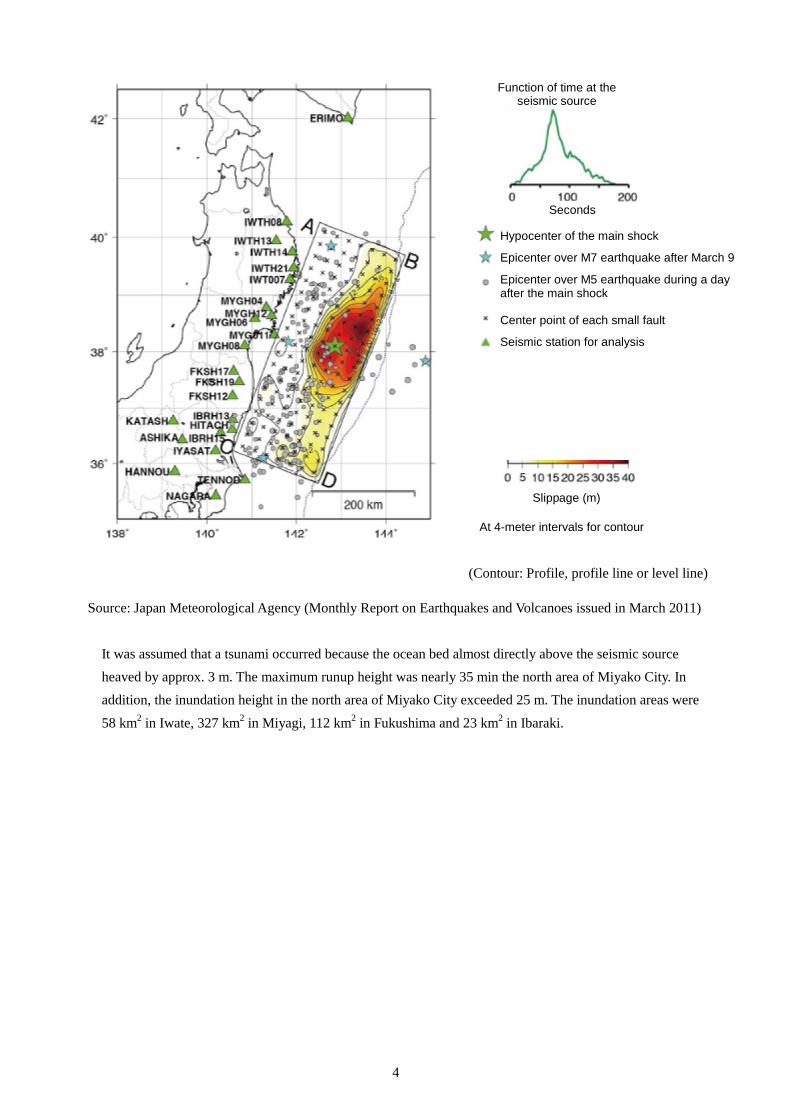
Kurihara City, Miyagi Prefecture in this earthquake. In addition, a very large tsunami was observed on the Pacific coasts of Hokkaido, Tohoku and Kanto districts. The seismic source of this earthquake was off the coast of Sanriku at a latitude of 38.1 degrees north and longitude 142.9 degrees east in the east-southeast 130 km from Oshika Peninsula and the focal depth was 24 km. The focal area extended from off the coasts of the Iwate to Ibaraki Prefectures with a length about
500 km and width of about 200 km. Moreover, the reported maximum slippage exceeded 50 m. In this earthquake, a large amount of slippage was observed in the areas close to the sea trench in the south area off the coast of Sanriku as well as close to the sea trench through the north area off the coast of Sanriku to off the coast of Boso. This was a giant earthquake with a magnitude of 9.0 (the fourth largest on the world record) and it occurred simultaneously in multiple areas including the central area off the coast of Sanriku, and off the coasts of Miyagi, Fukushima and Ibaraki Prefectures as the focal area. Though The
Headquarters for Earthquake Research Promotion, the national survey & research facilities, had evaluated earthquake motion and tsunami in the individual areas with prior occurrences, an earthquake that occurs simultaneously in all these areas was not anticipated. The Special Committee at the Central Disaster Prevention Council also reported that a giant earthquake with a magnitude of 9.0, which could not be anticipated based on earthquake records for the past several centuries in Japan, did occur simultaneously in multiple areas as an earthquake with an extensive focal area.
The tsunami that was generated subsequent to this earthquake and induced the large-scale disaster on the Pacific coast of the Tohoku District had a tsunami magnitude (indicates a scale of tsunami) of 9.1 and was the fourth largest on the world record and the largest in Japan.
3
Isoseismal map off the coast of Sanriku at around 14:46 on March 11, 2011
Source: Japan Meteorological Agency (Earthquake off the cost of Sanriku at around 14:46 on March 11, 2011)
Epicenter
Intensity 7 Legend
Intensity 6 upper Intensity 6 lower
Intensity 5 lower
Intensity 5 upper
Intensity 4 Intensity 3
Intensity 2
Intensity 1
4
Source: Japan Meteorological Agency (Monthly Report on Earthquakes and Volcanoes issued in March 2011)
It was assumed that a tsunami occurred because the ocean bed almost directly above the seismic source heaved by approx. 3 m. The maximum runup height was nearly 35 min the north area of Miyako City. In addition, the inundation height in the north area of Miyako City exceeded 25 m. The inundation areas were
58 km2 in Iwate, 327 km2 in Miyagi, 112 km2 in Fukushima and 23 km2 in Ibaraki.
Function of time at the seismic source
Seconds
Hypocenter of the main shock
Epicenter over M7 earthquake after March 9
Epicenter over M5 earthquake during a day after the main shock
Center point of each small fault
Seismic station for analysis
Slippage (m)
At 4-meter intervals for contour
(Contour: Profile, profile line or level line)
5
Source: Expert Examination Committee on Earthquake and Tsunami Measures with Lessons Learned from the Tohoku–Pacific Ocean Earthquake Extracted from the 1st meeting material
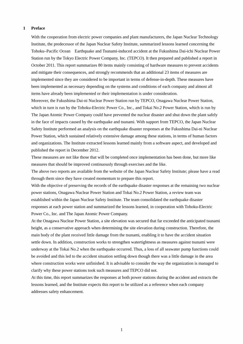
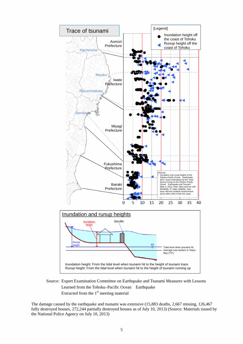
The damage caused by the earthquake and tsunami was extensive (15,883 deaths, 2,667 missing, 126,467 fully destroyed houses, 272,244 partially destroyed houses as of July 10, 2013) (Source: Materials issued by the National Police Agency on July 10, 2013)
Trace of tsunami
Hachinohe
Miyako
Rikuzentakata
Sendai
Aomori Prefecture
Iwate Prefecture
Miyagi Prefecture
Fukushima Prefecture
Ibaraki Prefecture
[Legend]
Inundation height off the coast of Tohoku Runup height off the coast of Tohoku
(Source) • Inundation and runup heights of the
Tohoku–Pacific Ocean Earthquake 2011: Quick estimations by the “Joint Survey Group on the Tohoku–Pacific Ocean Earthquake and Tsunami” (May 9, 2011). Note: Data used are with Reliability “A” (high reliability, clear trace with the smallest measurement error) within 200 m from the coast.
Inundation and runup heights
Runup height
Inundation height
Sea dike
Tidal level when tsunami hit Average sea surface in Tokyo Bay (T.P.)
Inundation height: From the tidal level when tsunami hit to the height of tsunami trace Runup height: From the tidal level when tsunami hit to the height of tsunami running up
6
3 3 Overview of the Onagawa Nuclear Power Station
3.1 Overall layout
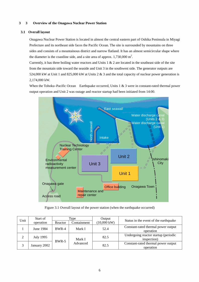
Onagawa Nuclear Power Station is located in almost the central eastern part of Oshika Peninsula in Miyagi Prefecture and its northeast side faces the Pacific Ocean. The site is surrounded by mountains on three
sides and consists of a mountainous district and narrow flatland. It has an almost semicircular shape where the diameter is the coastline side, and a site area of approx. 1,730,000 m2. Currently, it has three boiling water reactors and Units 1 & 2 are located in the southeast side of the site from the mountain side toward the seaside and Unit 3 in the southwest side. The generator outputs are 524,000 kW at Unit 1 and 825,000 kW at Units 2 & 3 and the total capacity of nuclear power generation is 2,174,000 kW.
When the Tohoku–Pacific Ocean Earthquake occurred, Units 1 & 3 were in constant-rated thermal power output operation and Unit 2 was outage and reactor startup had been initiated from 14:00.
Figure 3.1 Overall layout of the power station (when the earthquake occurred)
Unit Start of operation
Type Output (10,000 kW) Status in the event of the earthquake Reactor Containment
1 June 1984 BWR-4 Mark I 52.4 Constant-rated thermal power output operation
2 July 1995 BWR-5 Mark I
Advanced
82.5 Undergoing reactor startup (periodic inspection)
3 January 2002 82.5 Constant-rated thermal power output operation
East seawall
Water discharge canal (Units 2 & 3)
Water discharge canal (Unit 1)
Nor
th s
eaw
all
Intake
Nuclear Technology Training Center
Environmental radioactivity measurement center
Unit 3
Unit 2
Unit 1
Ishinomaki City
Onagawa gate
Access road Maintenance and repair center
Office building Onagawa Town
7
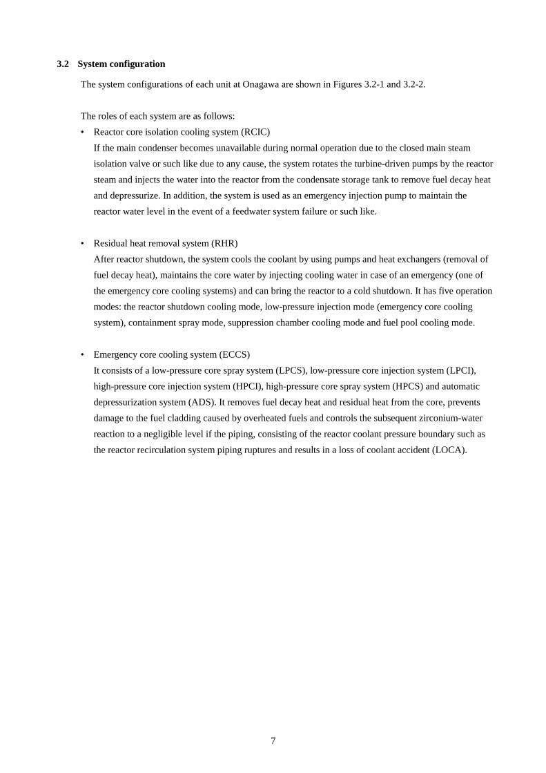
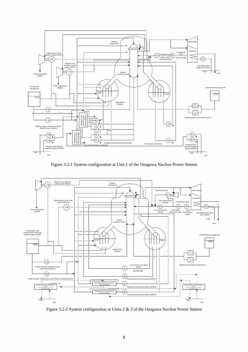
3.2 System configuration
The system configurations of each unit at Onagawa are shown in Figures 3.2-1 and 3.2-2.
The roles of each system are as follows: • Reactor core isolation cooling system (RCIC)
If the main condenser becomes unavailable during normal operation due to the closed main steam isolation valve or such like due to any cause, the system rotates the turbine-driven pumps by the reactor steam and injects the water into the reactor from the condensate storage tank to remove fuel decay heat and depressurize. In addition, the system is used as an emergency injection pump to maintain the reactor water level in the event of a feedwater system failure or such like.
• Residual heat removal system (RHR) After reactor shutdown, the system cools the coolant by using pumps and heat exchangers (removal of fuel decay heat), maintains the core water by injecting cooling water in case of an emergency (one of the emergency core cooling systems) and can bring the reactor to a cold shutdown. It has five operation modes: the reactor shutdown cooling mode, low-pressure injection mode (emergency core cooling system), containment spray mode, suppression chamber cooling mode and fuel pool cooling mode.
• Emergency core cooling system (ECCS)
It consists of a low-pressure core spray system (LPCS), low-pressure core injection system (LPCI), high-pressure core injection system (HPCI), high-pressure core spray system (HPCS) and automatic depressurization system (ADS). It removes fuel decay heat and residual heat from the core, prevents damage to the fuel cladding caused by overheated fuels and controls the subsequent zirconium-water
reaction to a negligible level if the piping, consisting of the reactor coolant pressure boundary such as the reactor recirculation system piping ruptures and results in a loss of coolant accident (LOCA).
8
Figure 3.2-1 System configuration at Unit 1 of the Onagawa Nuclear Power Station
Figure 3.2-2 System configuration at Units 2 & 3 of the Onagawa Nuclear Power Station
High-pressure core injection system (HPCI)
Reactor core isolation cooling system (RCIC)
To the suppression chamber
To the suppression chamber
Condensate storage tank
Control rod drive hydraulic system (CRD) (two systems)
Make-up water condensate system (MUWC) (two systems)
Residual heat removal seawater system (RHRS)
Sea
Res
idua
l hea
t re
mov
al s
yste
m
heat
exc
hang
er
To the water discharge canal (sea)
Res
idua
l hea
t re
mov
al s
yste
m
heat
exc
hang
er
To the water discharge canal (sea)
Reactor containment
Reactor pressure vessel
Suppression chamber
Residual heat removal system (RHR)
Feedwater pump
(three motor- operated pumps)
Condensate pump
(three pumps)
Main turbine
Condenser
Circulating water pump (two pumps)
Sea
Borated water storage tank
Standby liquid control system (SLC)
Core spray system (CS) Residual heat removal seawater system (RHRS)
Sea
Sea
Sea Sea
High-pressure core spray system (HPCS)
Reactor core isolation cooling system (RCIC)
To the suppression chamber
Condensate water storage tank/condensate water storage reservoir
Reactor building closed-cooling-water system
Reactor building closed cooling seawater system
Two motor-driven turbines
Two motor-driven pumps
Three high- pressure pumps
Three low-pressure
pumps
Low-pressure core spray system
Residual heat removal system (RHR) C
Residual heat removal system (RHR) B
Residual heat removal system (RHR) A
Reactor building closed-cooling-water system
Reactor building closed cooling seawater system
Residual heat removal system heat exchanger
Residual heat removal system heat exchanger
Control rod drive hydraulic system (CRD) (two systems)
Make-up water condensate system (MUWC) (three systems)
Suppression chamber
Reactor pressure vessel
Reactor containment
Feedwater pump
Condensate pump
Main turbine
Condenser
Circulating water pump (two pumps)
Borated water storage tank
Standby liquid control system (SLC)

9
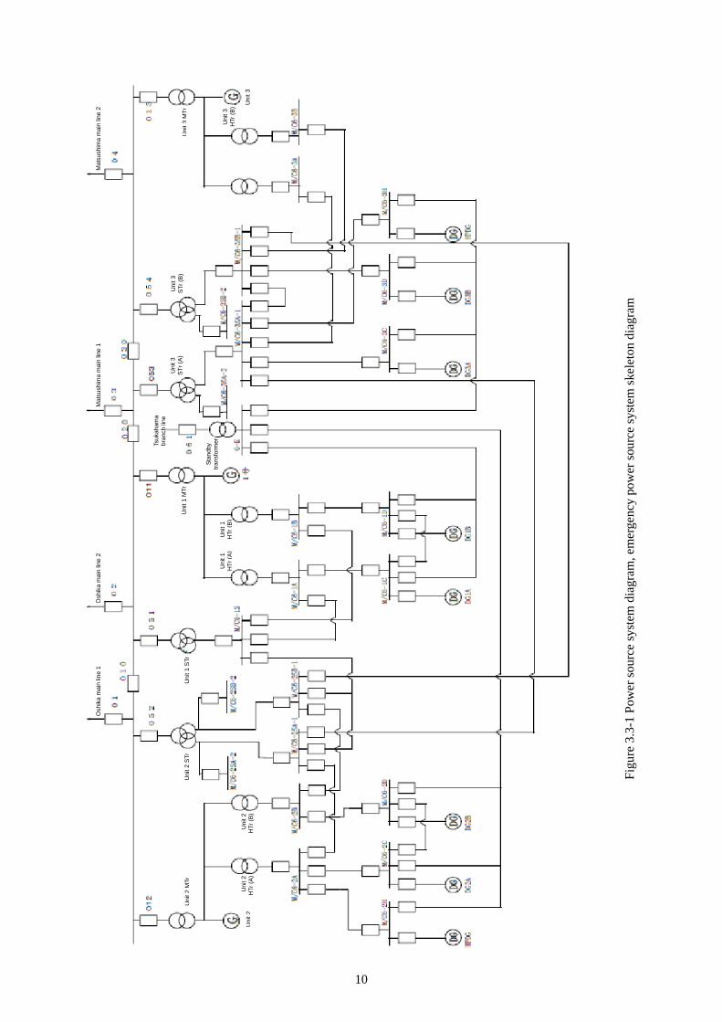
3.3 Power source system
The electricity generated at each unit is sent to the power source system via 275 kV transmission lines with four circuits. This 275 kV transmission line can be used to transmit all the electricity generated at the Onagawa Nuclear Power Station even if one circuit is unavailable. In addition, it can conduct full-power operation at the station in the event of an accident in one circuit.
Should all four circuits of the 275 kV transmission line lose power, the electricity for the system to safely shut down the reactor will be supplied from the emergency diesel generator, high-pressure core spray system (HPCS), diesel generator or one circuit of the 66 kV transmission line. One circuit of the 66 kV transmission line is shared among Units 1 – 3 and it receives power via the emergency transformer.
10
Figu
re 3
.3-1
Pow
er so
urce
syst
em d
iagr
am, e
mer
genc
y po
wer
sour
ce sy
stem
skel
eton
dia
gram
Osh
ika
mai
n lin
e 1
Osh
ika
mai
n lin
e 2
Mat
sush
ima
mai
n lin
e 1
Mat
sush
ima
mai
n lin
e 2
Uni
t 2 M
Tr
Uni
t 2
Uni
t 2
HTr
(A)
Uni
t 2
HTr
(B)
Uni
t 2 S
Tr
Uni
t 1 S
Tr
Uni
t 1
HTr
(A)
Uni
t 1
HTr
(B)
Uni
t 1 M
Tr
Tsuk
aham
a br
anch
line
Stan
dby
trans
form
er
Uni
t 3
STr
(A)
Uni
t 3
STr
(B)
Uni
t 3 M
Tr
Uni
t 3
HTr
(B) U
nit 3
11
4 Damage caused by the earthquake and tsunami at the Onagawa Nuclear Power Station
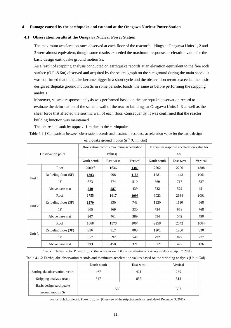
4.1 Observation results at the Onagawa Nuclear Power Station
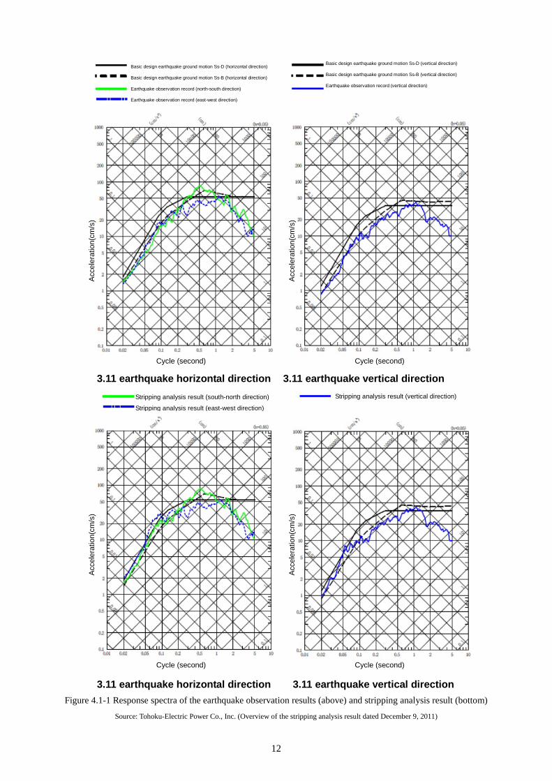
The maximum acceleration rates observed at each floor of the reactor buildings at Onagawa Units 1, 2 and 3 were almost equivalent, though some results exceeded the maximum response acceleration value for the
basic design earthquake ground motion Ss. As a result of stripping analysis conducted on earthquake records at an elevation equivalent to the free rock surface (O.P -8.6m) observed and acquired by the seismograph on the site ground during the main shock, it was confirmed that the quake became bigger in a short cycle and the observation record exceeded the basic design earthquake ground motion Ss in some periodic bands, the same as before performing the stripping analysis.
Moreover, seismic response analysis was performed based on the earthquake observation record to evaluate the deformation of the seismic wall of the reactor buildings at Onagawa Units 1–3 as well as the shear force that affected the seismic wall of each floor. Consequently, it was confirmed that the reactor building function was maintained. The entire site sank by approx. 1 m due to the earthquake.
Table 4.1-1 Comparison between observation records and maximum response acceleration value for the basic design
earthquake ground motion Ss*1 (Unit: Gal)
Observation point
Observation record (maximum acceleration
values)
Maximum response acceleration value for
Ss
North-south East-west Vertical North-south East-west Vertical
Unit 1
Roof 2000*2 1636 1389 2202 2200 1388
Refueling floor (5F) 1303 998 1183 1281 1443 1061
1F 573 574 510 660 717 527
Above base mat 540 587 439 532 529 451
Unit 2
Roof 1755 1617 1093 3023 2634 1091
Refueling floor (3F) 1270 830 743 1220 1110 968
1F 605 569 330 724 658 768
Above base mat 607 461 389 594 572 490
Unit 3
Roof 1868 1578 1004 2258 2342 1064
Refueling floor (3F) 956 917 888 1201 1200 938
1F 657 692 547 792 872 777
Above base mat 573 458 321 512 497 476
Source: Tohoku-Electric Power Co., Inc. (Report overview of the earthquake/tsunami survey result dated April 7, 2011)
Table 4.1-2 Earthquake observation records and maximum acceleration values based on the stripping analysis (Unit: Gal)
North-south East-west Vertical
Earthquake observation record 467 421 269
Stripping analysis result 517 636 312
Basic design earthquake
ground motion Ss 580 387
Source: Tohoku-Electric Power Co., Inc. (Overview of the stripping analysis result dated December 9, 2011)
12
3.11 earthquake horizontal direction 3.11 earthquake vertical direction
3.11 earthquake horizontal direction 3.11 earthquake vertical direction
Figure 4.1-1 Response spectra of the earthquake observation results (above) and stripping analysis result (bottom)
Source: Tohoku-Electric Power Co., Inc. (Overview of the stripping analysis result dated December 9, 2011)
Basic design earthquake ground motion Ss-D (horizontal direction)
Basic design earthquake ground motion Ss-B (horizontal direction)
Earthquake observation record (north-south direction)
Earthquake observation record (east-west direction)
Basic design earthquake ground motion Ss-D (vertical direction)
Basic design earthquake ground motion Ss-B (vertical direction)
Earthquake observation record (vertical direction) A
ccel
erat
ion(
cm/s
)
Acc
eler
atio
n(cm
/s)
Cycle (second) Cycle (second)
Stripping analysis result (south-north direction)
Stripping analysis result (east-west direction)
Stripping analysis result (vertical direction)
Acc
eler
atio
n(cm
/s)
Acc
eler
atio
n(cm
/s)
Cycle (second) Cycle (second)
13
(1) Maximum acceleration 2nd basement of the Unit 1 reactor building: 567.5 gal
(2) Distance from the Onagawa Power Station Distance to the epicenter: 123 km; distance to the seismic source: 125 km
(3) Tsunami data (i) Inundation height
O.P. + approx. 13 m*3 (ii) Inundation area
Not exceeding the site elevation (O.P. + approx. 13.8 m*3). Tsunami did not reach the major buildings though there was a trace of seawater inundation in part of the seaside at the site.
(4) Time when the maximum tsunami height was reached at the site At 15:29 on March 11, 2013
*1:
*2:
*3:
If there are multiple observation points in horizontal and vertical directions, the maximum value is indicated. Reference value because the observed value exceeded the maximum setpoints of the pertinent
seismograph (2000 gal) The average sea surface in Tokyo Bay (T.P.) = O.P. + 0.74 m and crustal deformation (approx. -1 m: Quick estimation) around the Onagawa Nuclear Power Station, which the Geospatial Information Authority of Japan announced after the earthquake, was taken into consideration.
14
4.2 Damage and impact from the earthquake
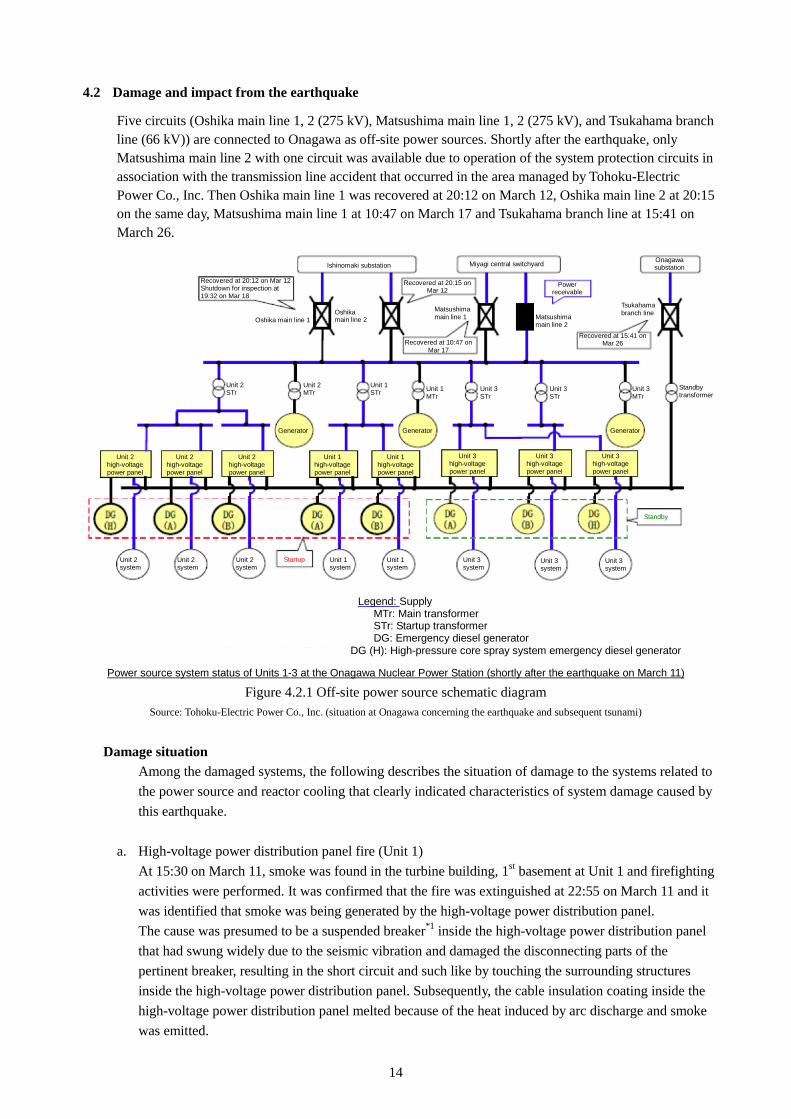
Five circuits (Oshika main line 1, 2 (275 kV), Matsushima main line 1, 2 (275 kV), and Tsukahama branch line (66 kV)) are connected to Onagawa as off-site power sources. Shortly after the earthquake, only Matsushima main line 2 with one circuit was available due to operation of the system protection circuits in association with the transmission line accident that occurred in the area managed by Tohoku-Electric Power Co., Inc. Then Oshika main line 1 was recovered at 20:12 on March 12, Oshika main line 2 at 20:15 on the same day, Matsushima main line 1 at 10:47 on March 17 and Tsukahama branch line at 15:41 on March 26.
Power source system status of Units 1-3 at the Onagawa Nuclear Power Station (shortly after the earthquake on March 11)
Figure 4.2.1 Off-site power source schematic diagram Source: Tohoku-Electric Power Co., Inc. (situation at Onagawa concerning the earthquake and subsequent tsunami)
Damage situation
Among the damaged systems, the following describes the situation of damage to the systems related to the power source and reactor cooling that clearly indicated characteristics of system damage caused by this earthquake.
a. High-voltage power distribution panel fire (Unit 1) At 15:30 on March 11, smoke was found in the turbine building, 1st basement at Unit 1 and firefighting activities were performed. It was confirmed that the fire was extinguished at 22:55 on March 11 and it was identified that smoke was being generated by the high-voltage power distribution panel. The cause was presumed to be a suspended breaker*1 inside the high-voltage power distribution panel that had swung widely due to the seismic vibration and damaged the disconnecting parts of the pertinent breaker, resulting in the short circuit and such like by touching the surrounding structures inside the high-voltage power distribution panel. Subsequently, the cable insulation coating inside the high-voltage power distribution panel melted because of the heat induced by arc discharge and smoke was emitted.
Recovered at 20:12 on Mar 12 Shutdown for inspection at 19:32 on Mar 18
Ishinomaki substation
Oshika main line 1Oshika main line 2
Recovered at 20:15 on Mar 12
Matsushima main line 1
Recovered at 10:47 on Mar 17
Miyagi central switchyard
Power receivable
Onagawa substation
Matsushima main line 2
Tsukahama branch line
Recovered at 15:41 on Mar 26
Unit 2 STr
Unit 2 MTr
Unit 1 STr Unit 1
MTr Unit 3 STr
Unit 3 STr
Unit 3 MTr
Standby transformer
Generator Generator Generator
Unit 2 high-voltage power panel
Unit 2 high-voltage power panel
Unit 2 high-voltage power panel
Unit 1 high-voltage power panel
Unit 1 high-voltage power panel
Unit 3 high-voltage power panel
Unit 3 high-voltage power panel
Unit 3 high-voltage power panel
Standby
Unit 2 system
Unit 2 system
Unit 2 system
Startup Unit 1 system
Unit 1 system
Unit 3 system
Unit 3 system
Unit 3 system
Legend: Supply MTr: Main transformer STr: Startup transformer DG: Emergency diesel generator
DG (H): High-pressure core spray system emergency diesel generator
15
b. Loss of the emergency diesel generator (A) functions (Unit 1) In the periodic testing on the emergency diesel generator (A) at the Onagawa Nuclear Power Station Unit 1 performed on April 1, the synchronoscope*2 to connect to the on-site power source system was not operating; thus, it was not possible to connect to the on-site power source system. Because of that, the inspection was performed for the synchronoscope circuit. During inspection, an event occurred where the breaker of the emergency diesel generator (A) was automatically loaded in a state where the emergency diesel generator (A) was not activated. Therefore, the inspection for the emergency diesel generator (A) was initiated from April 5. As a result of the inspection, damage to the circuit used for voltage adjustment and such like of the emergency diesel generator was confirmed. The presumed cause was an earth fault that occurred in the cable connecting the synchronoscope circuits affected by fire on the high-voltage power distribution panel, and this caused the fuse to blow due to the earth fault current that flowed when the synchronoscope switch was turned; thus the synchronoscope was not operated. In addition, the cable insulation coat connecting the synchronoscope circuits melted, affected by the fire of the pertinent high-voltage power distribution panel and another piece of insulation coating touched the melted cable, leading to the situation where a current flowed. Therefore, it was assumed that the breaker for the emergency diesel generator (A) was automatically loaded while detaching circuits from the high-voltage power distribution panel in association with the synchronoscope inspection, and this caused an overvoltage on the circuits used to adjust the voltage from the on-site power source system to the emergency diesel generator (A), resulting in damage. After it had been confirmed that the fuse of the synchronoscope had blown and that the circuits used for voltage adjustment had been replaced, an operation check was performed on May 18 and it was confirmed that the emergency diesel generator (A) had become operable.
c. Spent fuel pit cooling & clean up system stoppage (all Units) Though the spent fuel pit cooling & clean up system stopped at 14:47 on March 11 due to the earthquake, it was restarted after checking that there was no damage to the system. During the stoppage, there was no significant increase in the spent fuel pit temperature. The cause might be that the pump suction pressure of the spent fuel pit cooling & clean up system decreased because the level switch for “skimmer surge tank level low-low” was operated due to the earthquake or there was a temporary decrease of the spent fuel pit level due to the seismic shaking.
d. Startup transformer stoppage (Unit 1) As for the status of the power source, power was distributed to the site from Matsushima main line 2 as the off-site power source via the startup transformer. Since the startup transformer stopped at 14:55 on March 11, however, the on-site power source was unavailable and then the emergency bus received power from the emergency diesel generators (A) and (B) as designed. The cause was that earth fault and short circuit occurred inside the normal metal-clad switch gear 6-1A among the high-voltage power distribution panels (fire occurred subsequently) and the overcurrent relay for the startup transformer was activated. Then, the startup transformer was recovered at 02:05 on March 12 after checking that there was no abnormality in the startup transformer by carrying out a visual inspection and measuring insulation resistance. After the startup transformer was recovered, power for normal buses other than the normal metal-clad switch gear 6-1A was recovered in series.
*1: Component that automatically detaches the electric circuit when connecting the electric circuits or
overcurrent flows. *2: Component that checks whether the electric nature (voltage, frequency) is equivalent to mitigate
shock when manually connecting the diesel generator to the on-site power source system for periodic testing or such like. During loss of off-site power supply, the emergency diesel generator
16
will be connected automatically without using the synchronoscope because there is no electricity for the on-site power source system.
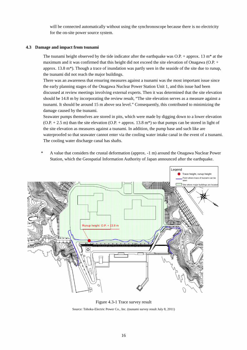
4.3 Damage and impact from tsunami
The tsunami height observed by the tide indicator after the earthquake was O.P. + approx. 13 m* at the maximum and it was confirmed that this height did not exceed the site elevation of Onagawa (O.P. + approx. 13.8 m*). Though a trace of inundation was partly seen in the seaside of the site due to runup, the tsunami did not reach the major buildings. There was an awareness that ensuring measures against a tsunami was the most important issue since the early planning stages of the Onagawa Nuclear Power Station Unit 1, and this issue had been discussed at review meetings involving external experts. Then it was determined that the site elevation should be 14.8 m by incorporating the review result, “The site elevation serves as a measure against a tsunami. It should be around 15 m above sea level.” Consequently, this contributed to minimizing the damage caused by the tsunami. Seawater pumps themselves are stored in pits, which were made by digging down to a lower elevation (O.P. + 2.5 m) than the site elevation (O.P. + approx. 13.8 m*) so that pumps can be stored in light of the site elevation as measures against a tsunami. In addition, the pump base and such like are waterproofed so that seawater cannot enter via the cooling water intake canal in the event of a tsunami. The cooling water discharge canal has shafts.
* A value that considers the crustal deformation (approx. -1 m) around the Onagawa Nuclear Power
Station, which the Geospatial Information Authority of Japan announced after the earthquake.
Figure 4.3-1 Trace survey result
Source: Tohoku-Electric Power Co., Inc. (tsunami survey result July 8, 2011)
Legend Trace height, runup height Point where trace of tsunami can be seen
Site where major buildings are located
Runup height: O.P. + 13.8 m
17
Damage situation Among the damaged systems, the following describes the situation of damage to the systems related to the power source and reactor cooling that clearly indicated characteristics of the system damage caused by this tsunami.
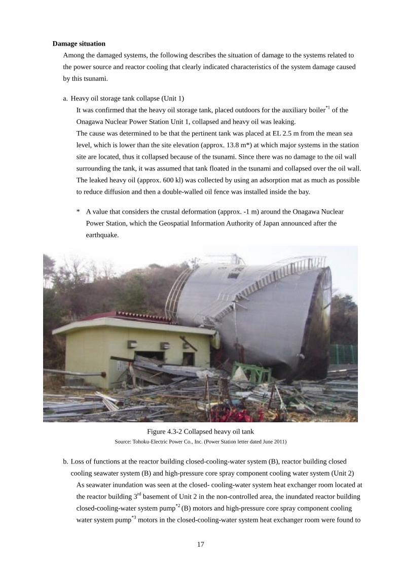
a. Heavy oil storage tank collapse (Unit 1)
It was confirmed that the heavy oil storage tank, placed outdoors for the auxiliary boiler*1 of the Onagawa Nuclear Power Station Unit 1, collapsed and heavy oil was leaking. The cause was determined to be that the pertinent tank was placed at EL 2.5 m from the mean sea level, which is lower than the site elevation (approx. 13.8 m*) at which major systems in the station
site are located, thus it collapsed because of the tsunami. Since there was no damage to the oil wall surrounding the tank, it was assumed that tank floated in the tsunami and collapsed over the oil wall. The leaked heavy oil (approx. 600 kl) was collected by using an adsorption mat as much as possible to reduce diffusion and then a double-walled oil fence was installed inside the bay.
* A value that considers the crustal deformation (approx. -1 m) around the Onagawa Nuclear
Power Station, which the Geospatial Information Authority of Japan announced after the earthquake.
Figure 4.3-2 Collapsed heavy oil tank
Source: Tohoku-Electric Power Co., Inc. (Power Station letter dated June 2011)
b. Loss of functions at the reactor building closed-cooling-water system (B), reactor building closed
cooling seawater system (B) and high-pressure core spray component cooling water system (Unit 2) As seawater inundation was seen at the closed- cooling-water system heat exchanger room located at the reactor building 3rd basement of Unit 2 in the non-controlled area, the inundated reactor building closed-cooling-water system pump*2 (B) motors and high-pressure core spray component cooling water system pump*3 motors in the closed-cooling-water system heat exchanger room were found to
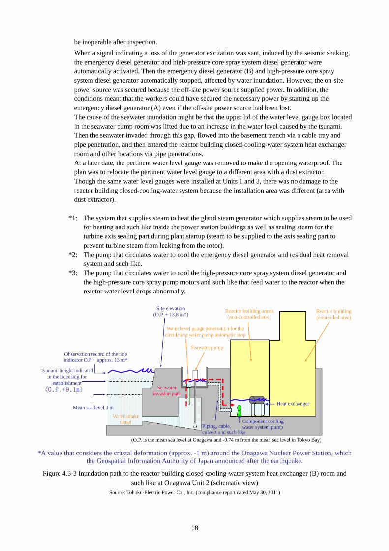
18
be inoperable after inspection. When a signal indicating a loss of the generator excitation was sent, induced by the seismic shaking, the emergency diesel generator and high-pressure core spray system diesel generator were automatically activated. Then the emergency diesel generator (B) and high-pressure core spray system diesel generator automatically stopped, affected by water inundation. However, the on-site power source was secured because the off-site power source supplied power. In addition, the conditions meant that the workers could have secured the necessary power by starting up the emergency diesel generator (A) even if the off-site power source had been lost. The cause of the seawater inundation might be that the upper lid of the water level gauge box located in the seawater pump room was lifted due to an increase in the water level caused by the tsunami. Then the seawater invaded through this gap, flowed into the basement trench via a cable tray and pipe penetration, and then entered the reactor building closed-cooling-water system heat exchanger room and other locations via pipe penetrations. At a later date, the pertinent water level gauge was removed to make the opening waterproof. The plan was to relocate the pertinent water level gauge to a different area with a dust extractor. Though the same water level gauges were installed at Units 1 and 3, there was no damage to the reactor building closed-cooling-water system because the installation area was different (area with dust extractor).
*1: The system that supplies steam to heat the gland steam generator which supplies steam to be used
for heating and such like inside the power station buildings as well as sealing steam for the turbine axis sealing part during plant startup (steam to be supplied to the axis sealing part to prevent turbine steam from leaking from the rotor).
*2: The pump that circulates water to cool the emergency diesel generator and residual heat removal system and such like.
*3: The pump that circulates water to cool the high-pressure core spray system diesel generator and the high-pressure core spray pump motors and such like that feed water to the reactor when the reactor water level drops abnormally.
*A value that considers the crustal deformation (approx. -1 m) around the Onagawa Nuclear Power Station, which the Geospatial Information Authority of Japan announced after the earthquake.
Figure 4.3-3 Inundation path to the reactor building closed-cooling-water system heat exchanger (B) room and such like at Onagawa Unit 2 (schematic view)
Source: Tohoku-Electric Power Co., Inc. (compliance report dated May 30, 2011)
Observation record of the tide indicator O.P + approx. 13 m*
Tsunami height indicated in the licensing for
establishment
Mean sea level 0 m Water intake
canal
Site elevation (O.P. + 13.8 m*)
Reactor building annex (non-controlled area)
Water level gauge penetration for the circulating water pump automatic stop
Seawater pump
Seawater invasion path
Piping, cable, culvert and such like
Component cooling water system pump
Reactor building (controlled area)
Heat exchanger
(O.P. is the mean sea level at Onagawa and -0.74 m from the mean sea level in Tokyo Bay)
19
5 Responses to the earthquake disaster at the Onagawa Nuclear Power Station
5.1 Overview of responses right after the earthquake and tsunami for recovery and cold shutdown
As Units 1 and 3 were in constant-rated thermal power output operation and Unit 2 was undergoing a reactor startup at the Onagawa Nuclear Power Station, “a seismic acceleration high” signal was sent, induced by the Tohoku–Pacific Ocean Earthquake and reactors at all units were automatically shut down. Since Matsushima main line 2 remained functional out of the five circuits as the off-site power source, Units 2 and 3 received power via the startup transformer and the on-site power was secured. At Unit 1, the emergency diesel generator was activated because the startup transformer stopped after the earth fault of the normal buses caused by the earthquake. In addition, the reactor core isolation cooling system was activated for cooling the reactor by utilizing power from the DC power source. Pressure was controlled through the main steam relief valves. After depressurization, the control rod drive hydraulic system fed the water to the reactor. The residual heat removal system was used to cool the suppression chamber and reactor, resulting in a cold shutdown at 00:58 on March 12. At Unit 2, the reactor was subcritical with a reactor water temperature of less than 100ºC just before the earthquake; therefore, the reactor entered a cold shutdown condition by putting the reactor mode switch in the “shutdown” position at 14:49 on March 11. Seawater flowed in from the cooling water canal of the seawater pump room, intruded the reactor building via the underground trench and caused loss of functions in the reactor building closed-cooling-water system (B) and high-pressure core spray component cooling water system. However, the reactor cooling function was secured by the residual heat removal system (A) because the reactor building closed-cooling-water system (A) was intact. Moreover, it was assumed that the circulating water pump automatically stopped because the water level detector for seawater pumps was damaged by anaseism. At Unit 3, the circulating water pump automatically stopped as the water level detector for seawater pumps was damaged by anaseism and the signal was sent indicating a very low water level in the seawater pump room. Furthermore, the reactor core isolation cooling system was manually activated for reactor cooling after stopping the reactor feedwater pumps because the turbine building closed cooling seawater system lost its functions. Pressure was controlled through the main steam relief valves. After depressurizing the reactor, MUWC fed water to the reactor. The residual heat removal system was used to cool the suppression chamber and reactor, resulting in a cold shutdown at 01:17 on March 12. Cooling systems for the spent fuel pool also stopped automatically, affected by the seismic shaking; however, they were resumed after checking that there was no abnormality in the systems, and no significant increase in temperature was detected. As for the off-site power source, Oshika main lines 1 and 2 were recovered at 20:12 and 20:15 the next day (March 12) respectively. In addition, the startup transformer for Unit 1 was recovered at 02:05 on March 12.
5.2 Situation of the earthquake disaster responses 5.2.1 Immediately after the earthquake occurred
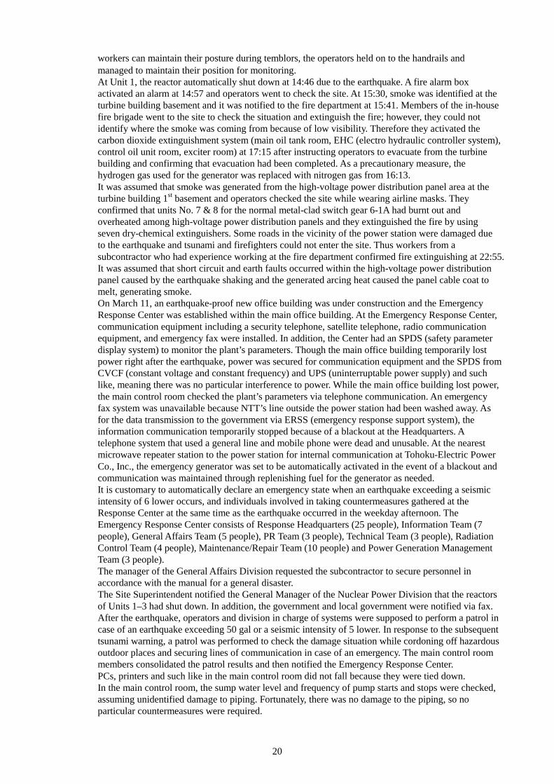
Immediately after the earthquake, the Emergency Response Center was established at the power station as well as Headquarters to implement countermeasures. The Emergency Disaster Response Center at the Headquarters was company-wide and the Nuclear Power Division, as the Nuclear Power Team, served as a contact with the nuclear power station. The Headquarters provided support in arranging materials and equipment, food and such like, and taking procedures for recovery. The Emergency Response Center at the Headquarters was fully occupied with trying to understand the system damage in the entire Tohoku District, arranging materials and equipment for recovery, dealing with PR activities and customers; thus, the situation did not allow it to focus solely on nuclear power-related matters. When the earthquake occurred, the Chief Engineer of Reactors for Units 1 & 2 was in the main control room for Units 1 & 2 to supervise a startup operation for Unit 2. In response to the plant shutdown due to the earthquake, he instructed reactor cooling operations for Unit 1. Due to the subsequent fire at Unit 1 and inundation at Unit 2 and such like, he gave instructions and supervision to the main control room operators for nearly 5 hours until the measures taken were established. In the event of the earthquake, lighting fixtures and a louver fell from the ceiling and scattered in the main control room. Moreover, part of the hanging smoke-proof barrier was damaged. Because of that, operators took actions while wearing helmets. As handrails are installed on the control panel so that
20
workers can maintain their posture during temblors, the operators held on to the handrails and managed to maintain their position for monitoring. At Unit 1, the reactor automatically shut down at 14:46 due to the earthquake. A fire alarm box activated an alarm at 14:57 and operators went to check the site. At 15:30, smoke was identified at the turbine building basement and it was notified to the fire department at 15:41. Members of the in-house fire brigade went to the site to check the situation and extinguish the fire; however, they could not identify where the smoke was coming from because of low visibility. Therefore they activated the carbon dioxide extinguishment system (main oil tank room, EHC (electro hydraulic controller system), control oil unit room, exciter room) at 17:15 after instructing operators to evacuate from the turbine building and confirming that evacuation had been completed. As a precautionary measure, the hydrogen gas used for the generator was replaced with nitrogen gas from 16:13. It was assumed that smoke was generated from the high-voltage power distribution panel area at the turbine building 1st basement and operators checked the site while wearing airline masks. They confirmed that units No. 7 & 8 for the normal metal-clad switch gear 6-1A had burnt out and overheated among high-voltage power distribution panels and they extinguished the fire by using seven dry-chemical extinguishers. Some roads in the vicinity of the power station were damaged due to the earthquake and tsunami and firefighters could not enter the site. Thus workers from a subcontractor who had experience working at the fire department confirmed fire extinguishing at 22:55. It was assumed that short circuit and earth faults occurred within the high-voltage power distribution panel caused by the earthquake shaking and the generated arcing heat caused the panel cable coat to melt, generating smoke. On March 11, an earthquake-proof new office building was under construction and the Emergency Response Center was established within the main office building. At the Emergency Response Center, communication equipment including a security telephone, satellite telephone, radio communication equipment, and emergency fax were installed. In addition, the Center had an SPDS (safety parameter display system) to monitor the plant’s parameters. Though the main office building temporarily lost power right after the earthquake, power was secured for communication equipment and the SPDS from CVCF (constant voltage and constant frequency) and UPS (uninterruptable power supply) and such like, meaning there was no particular interference to power. While the main office building lost power, the main control room checked the plant’s parameters via telephone communication. An emergency fax system was unavailable because NTT’s line outside the power station had been washed away. As for the data transmission to the government via ERSS (emergency response support system), the information communication temporarily stopped because of a blackout at the Headquarters. A telephone system that used a general line and mobile phone were dead and unusable. At the nearest microwave repeater station to the power station for internal communication at Tohoku-Electric Power Co., Inc., the emergency generator was set to be automatically activated in the event of a blackout and communication was maintained through replenishing fuel for the generator as needed. It is customary to automatically declare an emergency state when an earthquake exceeding a seismic intensity of 6 lower occurs, and individuals involved in taking countermeasures gathered at the Response Center at the same time as the earthquake occurred in the weekday afternoon. The Emergency Response Center consists of Response Headquarters (25 people), Information Team (7 people), General Affairs Team (5 people), PR Team (3 people), Technical Team (3 people), Radiation Control Team (4 people), Maintenance/Repair Team (10 people) and Power Generation Management Team (3 people). The manager of the General Affairs Division requested the subcontractor to secure personnel in accordance with the manual for a general disaster. The Site Superintendent notified the General Manager of the Nuclear Power Division that the reactors of Units 1–3 had shut down. In addition, the government and local government were notified via fax. After the earthquake, operators and division in charge of systems were supposed to perform a patrol in case of an earthquake exceeding 50 gal or a seismic intensity of 5 lower. In response to the subsequent tsunami warning, a patrol was performed to check the damage situation while cordoning off hazardous outdoor places and securing lines of communication in case of an emergency. The main control room members consolidated the patrol results and then notified the Emergency Response Center. PCs, printers and such like in the main control room did not fall because they were tied down. In the main control room, the sump water level and frequency of pump starts and stops were checked, assuming unidentified damage to piping. Fortunately, there was no damage to the piping, so no particular countermeasures were required.
21
Figure 5.2.1-1 Emergency disaster response system and main duties
5.2.2 Immediately after tsunami arrived
A monitor TV (CRT) for an ITV monitoring panel that was placed in the main control room at Unit 2 fell but was recovered to its original state. Footage around the cooling water intake canal was selected for the ITV monitoring board before the earthquake; thus, the recovered monitor TV screen recorded the arrival of the tsunami. Immediately after checking the monitor TV screen, it was found that oil from the heavy oil tank at Unit 1 had been half soaked in seawater. Then the arrival of the tsunami was promptly notified to the Emergency Response Center. In addition, an evacuation directive was given via paging. The tide indicator became unable to show values because of the first anaseism, and the indicator lost its function. After the situation was resolved, it was confirmed that the time at which the tsunami reached its maximum height was 15:29, and the height was 13 m, according to the record of the backup tide indicator. After the tsunami arrived, NTT’s external line was disconnected and communication to the local government via fax and telephone became unavailable. Mobile phones were also unusable. Because of that, the power station contacted the Headquarters via fax using the security line and the Headquarters provided
Secretariat 1. Establish the Emergency Response Center and general affairs
2. Communicate weather, damage information, directive internally
3. Contact with public offices and related bodies
General Affairs Team 1. Understand the damage to general affairs-related systems
2. Security inside and outside the power station site 3. Designate and request the evacuation space 4. Handle other matters that do not apply to other teams
PR Team 1. Handle affairs to deal with press relations
Local General Office Team 1. Deal with local responses
Emergency Disaster Response Center
Chief: Site Superintendent
Technical Team 1. Understand damage to the Technical Division-related systems
2. Handle technical matters that do not apply to other teams
Radiation Control Team 1. Understand damage to the radiation control-related systems
Repair/Maintenance Team 1. Understand damage to the Repair/Maintenance Division-related systems
Electric Maintenance/repair Team 1. Understand damage to the Electric
Maintenance/Repair Division-related systems 2. Secure power 3. Secure communication systems
Mechanical Maintenance/ Repair Team
1. Understand damage to the Mechanical Maintenance/Repair Division-related systems
Civil Engineering Team 1. Understand damage to the Civil Engineering Division-related systems
Power Generation Management Team
1. Understand damage to the Power Generation Management Division-related systems
2. Maintain security on power station facilities
22
information to the government and local government. At Unit 2, a generator excitation loss signal was sent, induced by the earthquake’s shaking and the emergency diesel generators (A), (B) and (H) automatically activated. Due to the tsunami, seawater flowed into the reactor building closed-cooling-water system heat exchanger (B) room in the non-controlled area of the reactor building 3rd basement, the high-pressure core spray component cooling water system heat exchanger room and stair hall to access the elevator area. And then the reactor building closed-cooling-water system pumps (B), (D) and high-pressure core spray component cooling water system pump were soaked. Because of that, the reactor building closed-cooling-water system pump (B) automatically stopped at 15:34 and the pertinent system pump (D), which was activated as a backup, also stopped immediately. Thus no cooling water was supplied and the emergency diesel generator (B) automatically stopped at 15:35. Moreover, the high-pressure core spray component cooling water system pump automatically stopped at 15:41, and as a result, no cooling water was supplied to the emergency diesel generator (H), leading to an automatic stoppage at 15:42. Seawater also invaded the reactor building closed-cooling-water system heat exchanger (A) room. At the spent fuel pool, a little amount of water spattered outside the pool by sloshing but the area surrounding the indoor pool was only slightly wet. As measures taken after the Niigataken Chuetsu-oki Earthquake, leak prevention to the outside and penetration seal reinforcement had been implemented.
5.2.3 Measures for recovery after tsunami arrived
(1) Actions and operations for recovery As power was secured and the functions of equipment required for cooling were not lost, operations for the reactor cold shutdown were in accordance with the manual, and they led to a cold shutdown through proper operations in the main control room. At Unit 2, seawater that had flowed from the cooling water intake canal at the seawater pump room entered the reactor building via an underground trench, and the seawater was discharged in two phases by using eight temporary discharging pumps and installing a cesspool for relay. For discharging, it was confirmed that no radioactive materials were contained by sampling the liquid beforehand. For laying temporary cables to secure power for these discharge pumps, stored cables and materials and equipment and those provided from the subcontractor were used. An acting Site Superintendent gave instructions for such actions. As large aftershocks continued, a patrol was performed as needed and the results were notified to the government and local government. This patrol and communication became heavy burdens. Directed by the Headquarters, maintaining and recovering the nuclear-related security communication network was prioritized. Aiming for recovery, the Emergency Response Center at the Headquarters kept inquiries to the minimum necessary level and responded to requests from the site so that the power station could focus on recovery operations. Moreover, the minimum necessary level of TV conferences were held. (2) Arrangement of personnel and materials and equipment At Units 1 & 2, 11 operators for a training shift and 18 day shifts were present and two teams were organized for Units 1 & 2 and Unit 3 as supporters for main control room operations and they worked on recovery in a two-shift system. After March 13, people who came to the site routinely and those who could reach the site via a security line from the nearest business office gathered and assumed duties in a three-shift system. All access roads to the power station were severed. An employee who went to Sendai for a business trip tried to reach the power station on the day after the earthquake and used the Cobalt Line because he thought it was easy to access it from the mountain road. However, the road was impassable from Kozumi IC and he reached the power station by walking. After that, a patrol was dispatched to check the

23
condition of each access road from the power station and it found that all access roads were severed. In a discussion between the Headquarters and Miyagi Prefecture, it was revealed that it took five days to recover the roads by using heavy equipment stored in the site for snow removal and improvement work. Making use of the past experience to recover the severed road caused by a typhoon, the access road was recovered by the plant’s own initiatives. After Day 2, people at the Emergency Response Center took breaks on a rotating basis. However, they could not return to their homes because the roads were severed. Thus each division secured a space for a sleep break, such as a meeting room within the office and training center, and they only had the clothes they were wearing. As blankets were delivered by helicopter, they were handed to those who evacuated first and site personnel received blankets from the fourth day. Since seven days’ worth of light oil for diesel generators was in stock, no additional replenishment was needed. The light oil transport pipe had not been affected by the tsunami because it was installed in an underground trench. Light oil for the emergency diesel generator (B) in Unit 2, whose function was lost due to inundation, was used for heavy equipment. At first, extracting oil was difficult without antistatic hoses and a 1 L bottle for sampling was used instead. In addition, light oil was used for a water carrier and large vehicles. As there was no stock of gasoline, a few dozen liters of gasoline were transported every day from the Headquarters by using portable cans after the land route had been recovered. Power-supply vehicles waited in Ishinomaki because they could not reach the power station due to the damaged access roads. Ultimately, their arrival at the power station was not necessary because Oshika main lines 1 & 2 were recovered at 20:12 and 20:15 respectively on March 12. The Headquarters arranged a helicopter on March 11 and used it for transportation. Originally, the helicopter was needed to check the integrity of transmission lines after the earthquake and such like. However, one helicopter was secured for the nuclear power station. The helicopter waited at Sendai Airport and the manual specified evacuation to higher ground in the case of an earthquake; thus, it could be used since it received no damage from the tsunami. In addition, securing a helicopter by contacting a helicopter operation company, which is not a group company, was a substantial aid as a means of transportation. The helicopter made 21 deliveries in the first three days. A heliport was located in a distant place within the site, and packages were transported by on-site vehicles by sheer force of numbers. Normal mobile phones were unavailable for communication with people carrying out off-site operations, and so radio equipment was effective. In addition, PHS devices were very effective for on-site communication. They were unusable in some areas because of a damaged antenna; however, communication during operation could be secured without trouble after the antennas were repaired. Moreover, a satellite telephone was used for communication with external organizations such as the local government (Onagawa Town). However, the number of satellite telephones at the site was small, and so it was hard to maintain sufficient communication. The paging system receives power from an emergency power source, and batteries when the AC power source is lost. Thus, the Manager of the Power Generation Division directed an evacuation due to the earthquake and tsunami via the paging system. There was no damage to radiation control materials and equipment caused by the earthquake and tsunami, and so there was no trouble with operations and no insufficiency of materials. There were 500 people and there were three days’ worth of food and drinking water (1500 L) in stock. However, stock for the affiliate companies and subcontractors was not sufficient. In addition, community people evacuated to the site and only one day’s worth of food and drinking water was secured for a total of 1,800 people as of March 12. Until recovery of the roads on March 16, food was procured from the coverage area of Tohoku Electric Power Co., Inc. on the Sea of Japan side with less damage and the helicopter transported food to the power station. Around one or two light meals were served a day. The water intake and headrace systems for domestic-use water were damaged by the earthquake, and use of domestic-use water was restricted. Furthermore, the Headquarters arranged for alternate delivery
24
vehicles and obtained approval from the river manager to intake water, and the water was secured as a result. Temporary pumps were placed in the river and the delivery vehicles transported the water back and forth and delivered approx. 400 t a day. Temporary water flowing in all lines was completed in late April because connections of buried pipes were damaged by the earthquake and drilling the ground was necessary for repair. Mainly two health promotion staff members with a nursing qualification managed the health of site personnel and community people who evacuated to the on-site gym. A psychological counselor came to the site to offer counseling. Around 16:00 on March 11, local residents including the Ward Mayor who were in an isolated area due to the severed roads requested evacuation to the PR center in the power station. However, the PR center had also lost power and the Site Superintendent determined he would accept those people to the site. In terms of nuclear material protection, the Ward Mayor was designated as a guarantor. Such acceptance was notified to the government. At first, they evacuated by walking and then a bus was sent from the power station. The number of evacuated people was 364 at the maximum on March 14. As evacuated people were moving in and out, their access control was troublesome. This acceptance of community people was notified to the local government, and the place was designated as an evacuation space of Onagawa Town on March 16. After that, staff members of the local government were stationed there and they dealt with community people. People who found the new evacuation place left and all left on June 6. Until food was received from the local government, the emergency food stocked at the power station was served. For drinking water, the stock of plastic bottles was distributed. After recovery of the water network within the power station, tap water was used. The Headquarters were asked to arrange daily commodities at the request of the evacuated people and transport them by helicopter. Furthermore, the helicopter was used to transport pregnant women and those requiring oxygen tanks among the evacuated people. Moreover, the power station accepted ships, which had sailed off the coast to avoid the tsunami, in the bay of the station because ports were damaged. Around 02:00 on March 13, an indicative value on the monitoring post reached a peak and exceeded 5 μSv/h, which is the notification standard in Article 10 of the Special Law of Emergency Preparedness for Nuclear Disaster. Therefore a notification was made in accordance with that. The power station was fully occupied with recovering the plant, and so there was almost no information on the Fukushima Dai-ichi Power Station accident. The Headquarters had a discussion with the regulatory agency to see if notification was unnecessary because it was clear that this radiation increase was due to the impact of the Fukushima Dai-ichi accident. However, the regulatory agency instructed the Headquarters to take procedures in accordance with the law and then the notification was made. After that, periodic communication was necessary for the subsequent three months. The Self-Defense Forces received many calls for service and contacted the power station for support after 4 or 5 days had passed.
25
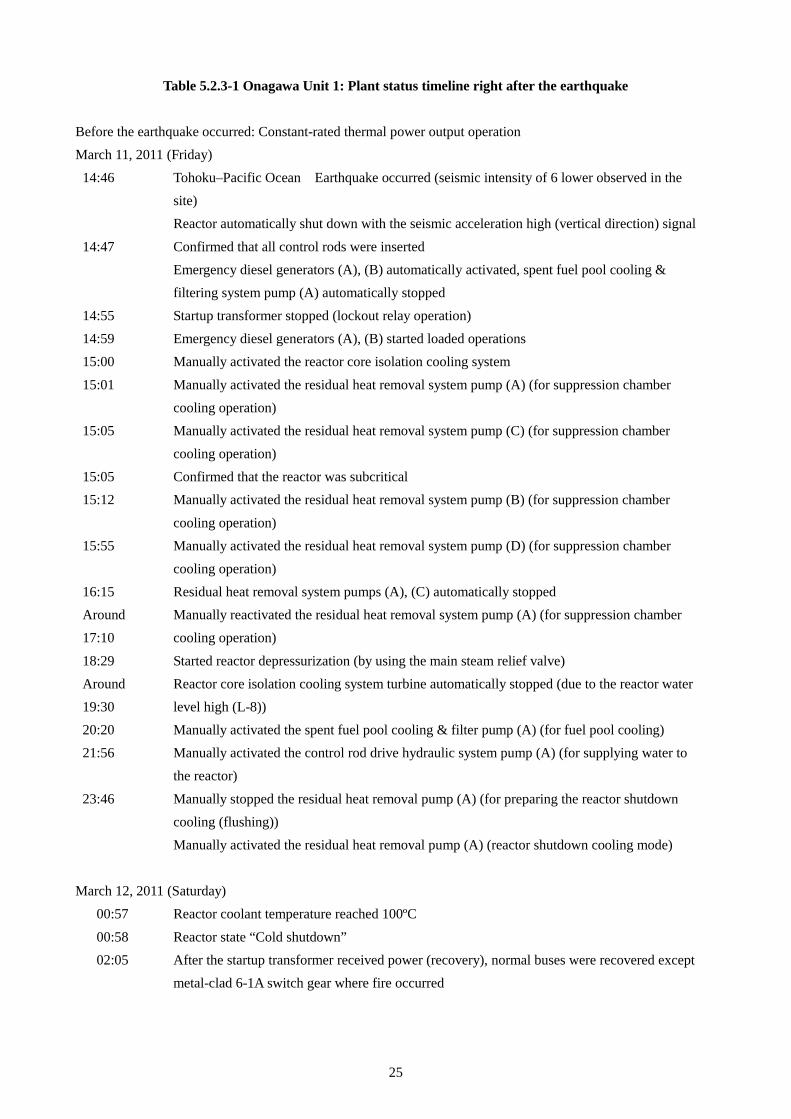
Table 5.2.3-1 Onagawa Unit 1: Plant status timeline right after the earthquake
Before the earthquake occurred: Constant-rated thermal power output operation March 11, 2011 (Friday)
14:46
14:47 14:55 14:59 15:00
15:01 15:05 15:05 15:12
15:55 16:15 Around 17:10
18:29 Around 19:30 20:20 21:56
23:46
Tohoku–Pacific Ocean Earthquake occurred (seismic intensity of 6 lower observed in the site) Reactor automatically shut down with the seismic acceleration high (vertical direction) signal
Confirmed that all control rods were inserted Emergency diesel generators (A), (B) automatically activated, spent fuel pool cooling & filtering system pump (A) automatically stopped Startup transformer stopped (lockout relay operation) Emergency diesel generators (A), (B) started loaded operations Manually activated the reactor core isolation cooling system
Manually activated the residual heat removal system pump (A) (for suppression chamber cooling operation) Manually activated the residual heat removal system pump (C) (for suppression chamber cooling operation) Confirmed that the reactor was subcritical Manually activated the residual heat removal system pump (B) (for suppression chamber
cooling operation) Manually activated the residual heat removal system pump (D) (for suppression chamber cooling operation) Residual heat removal system pumps (A), (C) automatically stopped Manually reactivated the residual heat removal system pump (A) (for suppression chamber cooling operation)
Started reactor depressurization (by using the main steam relief valve) Reactor core isolation cooling system turbine automatically stopped (due to the reactor water level high (L-8)) Manually activated the spent fuel pool cooling & filter pump (A) (for fuel pool cooling) Manually activated the control rod drive hydraulic system pump (A) (for supplying water to the reactor)
Manually stopped the residual heat removal pump (A) (for preparing the reactor shutdown cooling (flushing)) Manually activated the residual heat removal pump (A) (reactor shutdown cooling mode)
March 12, 2011 (Saturday)
00:57
00:58 02:05
Reactor coolant temperature reached 100ºC
Reactor state “Cold shutdown” After the startup transformer received power (recovery), normal buses were recovered except metal-clad 6-1A switch gear where fire occurred

26
Table 5.2.3-2 Onagawa Unit 2: Plant status timeline right after the earthquake
Before the earthquake occurred: Undergoing the 11th periodic inspection and shifted to “startup” right before the earthquake March 11, 2011 (Friday)
14:00
14:46 14:47
14:49 15:34 15:35
15:41 15:42 20:29
Reactor mode switch “Refueling” → “Startup” (reactor condition “Startup”) Started control rod withdrawal
Tohoku–Pacific Ocean Earthquake occurred (Seismic intensity 6 lower observed in the site) Reactor automatically shut down with the seismic acceleration high (horizontal direction in the reactor building bottom) signal Confirmed that all control rods were inserted Emergency diesel generators (A), (B), (H) automatically activated *Due to the generator excitation loss signal
Spent fuel pool cooling & filtering system pump (B) automatically stopped Reactor mode switch “Startup” → “Shutdown” (Reactor condition “Cold shutdown”) Reactor building closed-cooling-water system pumps(B), (D) automatically stopped (due to pump inundation) Emergency diesel generator (B) automatically stopped (due to the reactor building closed-cooling-water system (B), (D) stoppage)
High-pressure core spray component cooling water system pump automatically stopped (due to pump inundation) Emergency diesel generator (H) automatically stopped (due to high-pressure core spray component cooling water system stoppage) Manually activated the spent fuel pool cooling & filtering pump (A) (for fuel pool cooling)
March 12, 2011 (Saturday)
12:12 Manually activated the residual heat removal system pump (A) (reactor shutdown cooling mode)
27
Table 5.2.3-3 Onagawa Unit 2: Timeline for the reactor building closed-cooling-water system B, reactor building closed cooling seawater system B and high-pressure core spray component
cooling water system
March 11, 2011 (Friday) 14:00 14:46
14:49 Around 15:21 15:34
15:35 15:41 15:42
Around 16:00 16:01
16:06 Around 20:12 20:25
Reactor startup Earthquake occurred (seismic intensity of 6 lower observed in the site)
Reactor automatically shut down Emergency diesel generators (A), (B), (H) automatically activated (non-loaded operation) Major tsunami warning was issued First tsunami wave reached (visual inspection by operator) Reactor building closed-cooling-water system pump(B) automatically stopped Reactor building closed-cooling-water system pump(D) automatically stopped (stopped
immediately after backup pump activated) Emergency diesel generator (B) automatically stopped with “RCW (reactor building closed-cooling-water system) differential pressure low” signal High-pressure core spray component cooling water system pump automatically stopped Emergency diesel generator (H) automatically stopped with “HPCS (high-pressure core spray component cooling water system) differential pressure low” signal
Operators for site inspection found inundation at RCW heat exchanger (B) room at the lowest level of the non-controlled area at the reactor building, and 3rd basement stairs (two locations) to access the high-pressure core spray component cooling water system heat exchanger room, reactor building closed-cooling-water system heat exchanger (A) room Manually stopped the reactor building closed cooling seawater system pump (B) (due to inundation at the reactor building closed-cooling-water system B)
Manually stopped the high-pressure core spray component cooling seawater pump (due to inundation at the high-pressure core spray component cooling water system) No radioactivity was detected in the analysis of the invaded water and found that it was seawater Installed temporary pumps and started discharging seawater that had flowed into the 3rd basement of the reactor building (non-controlled area) to the outside
March 16, 2011
10:30 Completed discharging the invaded seawater
28
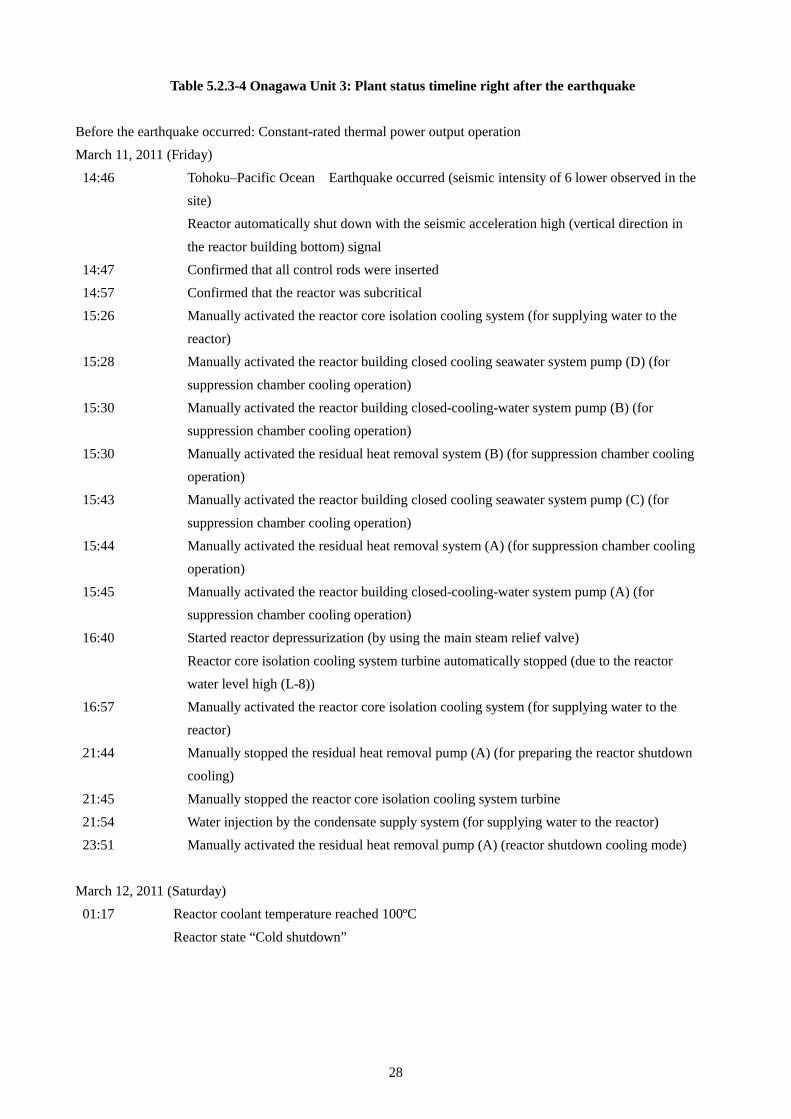
Table 5.2.3-4 Onagawa Unit 3: Plant status timeline right after the earthquake Before the earthquake occurred: Constant-rated thermal power output operation March 11, 2011 (Friday)
14:46
14:47 14:57 15:26 15:28
15:30 15:30 15:43
15:44 15:45 16:40
16:57 21:44
21:45 21:54 23:51
Tohoku–Pacific Ocean Earthquake occurred (seismic intensity of 6 lower observed in the site) Reactor automatically shut down with the seismic acceleration high (vertical direction in
the reactor building bottom) signal Confirmed that all control rods were inserted Confirmed that the reactor was subcritical Manually activated the reactor core isolation cooling system (for supplying water to the reactor) Manually activated the reactor building closed cooling seawater system pump (D) (for
suppression chamber cooling operation) Manually activated the reactor building closed-cooling-water system pump (B) (for suppression chamber cooling operation) Manually activated the residual heat removal system (B) (for suppression chamber cooling operation) Manually activated the reactor building closed cooling seawater system pump (C) (for
suppression chamber cooling operation) Manually activated the residual heat removal system (A) (for suppression chamber cooling operation) Manually activated the reactor building closed-cooling-water system pump (A) (for suppression chamber cooling operation) Started reactor depressurization (by using the main steam relief valve)
Reactor core isolation cooling system turbine automatically stopped (due to the reactor water level high (L-8)) Manually activated the reactor core isolation cooling system (for supplying water to the reactor) Manually stopped the residual heat removal pump (A) (for preparing the reactor shutdown cooling)
Manually stopped the reactor core isolation cooling system turbine Water injection by the condensate supply system (for supplying water to the reactor) Manually activated the residual heat removal pump (A) (reactor shutdown cooling mode)
March 12, 2011 (Saturday)
01:17 Reactor coolant temperature reached 100ºC
Reactor state “Cold shutdown”
29
6 Lessons learned from the earthquake disaster responses at the Onagawa Nuclear Power Station Based on the earthquake responses at the Onagawa Nuclear Power Station, it seems there are items that may be able to reduce operator burden at the site with some improvement, as well as items for which more effective measures may be taken by implementing the same measures at other power stations as good practice. These items are summarized below.
6.1 Organization, management, communication
• It is necessary to establish an emergency response system that can take cross-organizational measures for each issue at both the Headquarters and power station. Especially, preparation for logistical assistance is important.
• Deploying a contact person between the main control room and Emergency Response Center is effective for organizing the environment where operators can focus on plant operations.
• Company-wide logistical assistance (system, local, operation transfer, life support, situational check and such like) should be prepared so that the power station can focus on on-site responses in the case of an emergency.
• It needs to be recognized that support from the Self-Defense Forces cannot be expected immediately because they receive many calls for service when an emergency disaster happens.
6.2 Preparedness (system, manual, training)
• There is a need to work on further safety improvement measures (software, hardware) including emergency safety measures (short-term), emergency safety measures (mid and long term), and severe accident measures.
• For the case when an access road is severed, preparations should be made to handle the situation by combining multiple transfer and supply methods by road or air (including a sea route in some situations). In addition, it is recommended to prepare a helicopter and heavy equipment to transfer and transport supplies and secure heavy equipment operators for the case when an access road is severed.
• Even in a situation when a lighting fixture falls and scatters from the ceiling of the main control room or a fire and inundation occur simultaneously at the site, training should be performed continuously for operations in accordance with the emergency operation manual so that operators work without panicking in order to enhance their preparation for an emergency.
• Installing handrails on the control panel is very effective for helping operators to check values on instruments and carry out operations in the event of an earthquake. Moreover, seismic countermeasures for a ceiling and supplies in a main control room, such as tying down desktop PCs and printers with belts, is important to manage the operation environment.
• Preparation of materials and equipment such as temporary discharge pumps for building inundation caused by a tsunami is required.
• Assuming the case where a fire occurs when an access road is severed, it is necessary to arrange an on-site extinguishment system and in-house fire brigade so that they can make an initial response in the site. The in-house fire brigade should be trained to take actions even under conditions of low visibility caused by smoke. Moreover, a sufficient number of oxygen tanks for a fire site needs to be prepared for a smooth initial response.
• Countermeasures should be considered for cases where contaminated water is produced within a building in a non-controlled area.
• Assuming that light oil will be used from a light oil tank of emergency diesel generators when gasoline cannot be procured in the vicinity of the site, it is effective to prepare a diesel vehicle when renewing vehicles at the site as well as antistatic hoses to extract the light oil.
• Considering workers from subcontractors, water and food for 2,000 to 3,000 people should be secured and
30
so should a means of replenishing them. Water and food stocks reflect demand for affiliate companies and subcontractors.
• For outdoor and off-site operations when a mobile phone is unusable, a structure should be established to allow for communication of operation and seismic/tsunami information with the power station. It is effective to prepare a sufficient number of radios and satellite phones.
• Assuming the case where a general telephone line and mobile phone become unavailable, it is important to secure lines of communication with the government, local governments, plant manufacturers and such like, and during outdoor operations. In order to improve the reliability of communication systems, it is recommended to prepare a system that can receive power from an emergency power source or batteries and develop a structure for recovery and maintenance operations in case of trouble. In addition, it is recommended to secure a backup route for a TV conference line utilizing satellite communication. It is effective to have different and multiple-route configurations via a microwave wireless line and optical communication line (OPGW, optical ground wire) so as to secure communication reliability when using a security telephone and TV conference, and to preserve or maintain communication systems.
• As measures to secure plant maintenance personnel, it is recommended to prepare lodgings in the vicinity of the power station and establish a night-duty system at the power station involving affiliate companies.
6.3 Initial responses in the event of the earthquake
• If access to a fire site is impossible due to low visibility, fire extinguishing using a carbon dioxide extinguishment system is effective. Furthermore, it is necessary to make preparations in order to take countermeasures quickly to prevent the damage from expanding immediately in the event of a fire (replacing hydrogen gas of generators with nitrogen gas for discharge and such like).
• When an earthquake occurs, it is effective to check if a tsunami is coming to the site via an ITV camera in the main control room. It is also advisable for the office to prepare a method of checking and assessing the situation when a tsunami is coming, induced by an earthquake.
6.4 Additional measures
• Strengthening the reliability of off-site power is important. It is also important to enhance reliability (diversification, making other route, seismic proof and such like) of the system that supplies power from an off-site power source to the on-site emergency loads.
• It is recommended to install a backup emergency power source as power for operation systems at the on-site office.
• It is necessary to clarify the method of notifying the relevant parties when a tsunami is going to hit, other than by issuing an evacuation directive via the plant paging system, in the event of a tsunami warning. An evacuation space such as high ground also needs to be specified, considering the possibility of a large-scale tsunami.
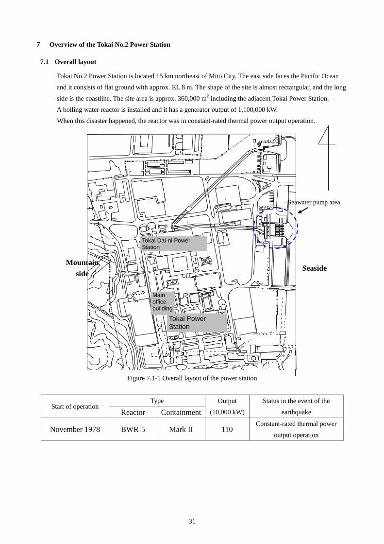
31
7 Overview of the Tokai No.2 Power Station
7.1 Overall layout
Tokai No.2 Power Station is located 15 km northeast of Mito City. The east side faces the Pacific Ocean and it consists of flat ground with approx. EL 8 m. The shape of the site is almost rectangular, and the long
side is the coastline. The site area is approx. 360,000 m2 including the adjacent Tokai Power Station. A boiling water reactor is installed and it has a generator output of 1,100,000 kW. When this disaster happened, the reactor was in constant-rated thermal power output operation.
東 海 発 電 所
事 務
本 館
東 海 第 二 発 電 所
Figure 7.1-1 Overall layout of the power station
Start of operation Type Output
(10,000 kW) Status in the event of the
earthquake Reactor Containment
November 1978 BWR-5 Mark II 110 Constant-rated thermal power
output operation
Mountain side
Seawater pump area
Seaside
Tokai Power Station
Main office building
Tokai Dai-ni Power Station
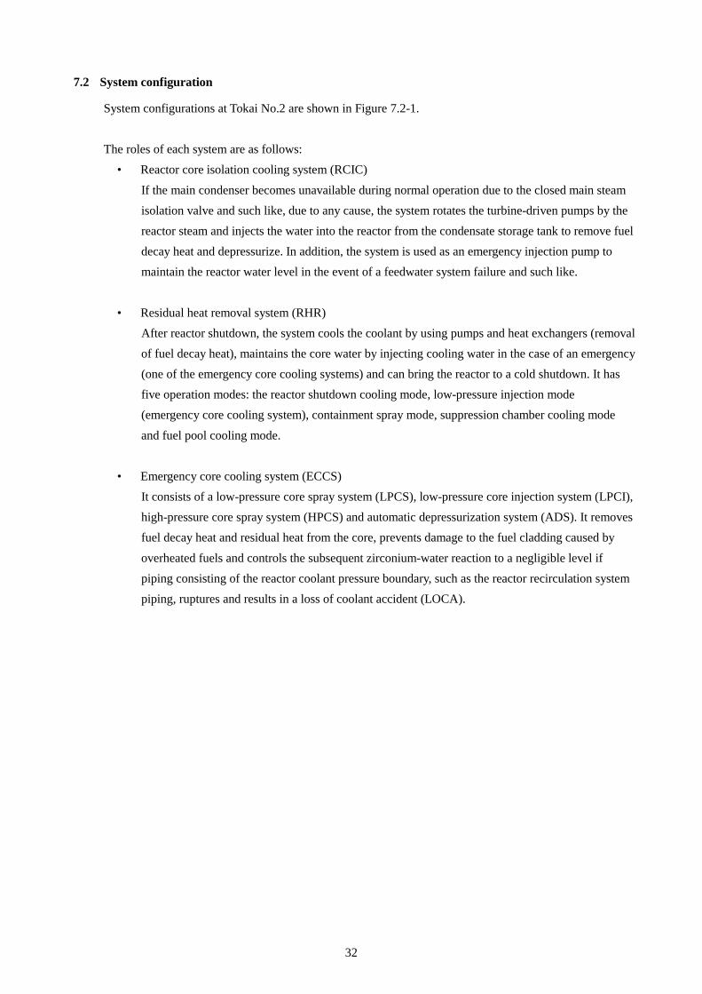
32
7.2 System configuration
System configurations at Tokai No.2 are shown in Figure 7.2-1.
The roles of each system are as follows: • Reactor core isolation cooling system (RCIC)
If the main condenser becomes unavailable during normal operation due to the closed main steam isolation valve and such like, due to any cause, the system rotates the turbine-driven pumps by the reactor steam and injects the water into the reactor from the condensate storage tank to remove fuel decay heat and depressurize. In addition, the system is used as an emergency injection pump to maintain the reactor water level in the event of a feedwater system failure and such like.
• Residual heat removal system (RHR) After reactor shutdown, the system cools the coolant by using pumps and heat exchangers (removal of fuel decay heat), maintains the core water by injecting cooling water in the case of an emergency (one of the emergency core cooling systems) and can bring the reactor to a cold shutdown. It has five operation modes: the reactor shutdown cooling mode, low-pressure injection mode (emergency core cooling system), containment spray mode, suppression chamber cooling mode
and fuel pool cooling mode.
• Emergency core cooling system (ECCS) It consists of a low-pressure core spray system (LPCS), low-pressure core injection system (LPCI), high-pressure core spray system (HPCS) and automatic depressurization system (ADS). It removes fuel decay heat and residual heat from the core, prevents damage to the fuel cladding caused by
overheated fuels and controls the subsequent zirconium-water reaction to a negligible level if piping consisting of the reactor coolant pressure boundary, such as the reactor recirculation system piping, ruptures and results in a loss of coolant accident (LOCA).
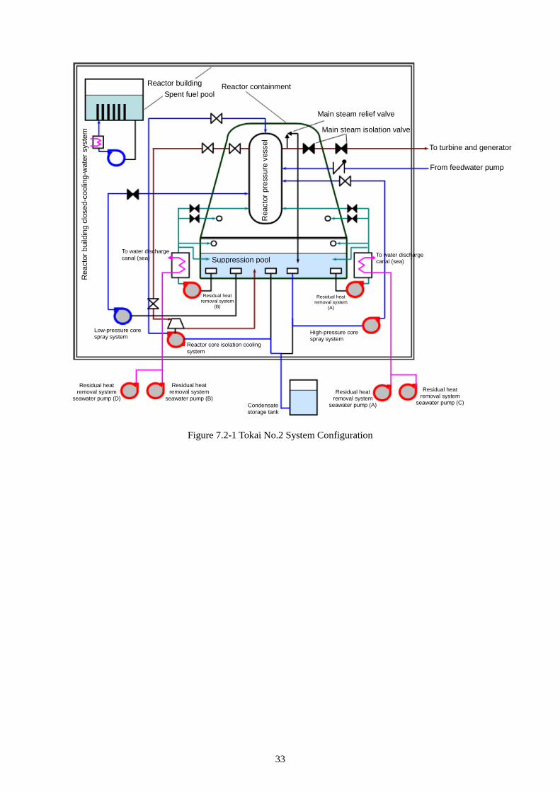
33
Figure 7.2-1 Tokai No.2 System Configuration
Rea
ctor
bui
ldin
g cl
osed
-coo
ling-
wat
er s
yste
m
Spent fuel pool Reactor containment Reactor building
Main steam relief valve
Main steam isolation valve
Rea
ctor
pre
ssur
e ve
ssel
To water discharge canal (sea) Suppression pool
To water discharge canal (sea)
To turbine and generator
From feedwater pump
Residual heat removal system
(B)
Residual heat removal system
(A)
Low-pressure core spray system
Reactor core isolation cooling system
High-pressure core spray system
Residual heat removal system
seawater pump (D)
Residual heat removal system
seawater pump (B) Condensate storage tank
Residual heat removal system
seawater pump (A)
Residual heat removal system
seawater pump (C)
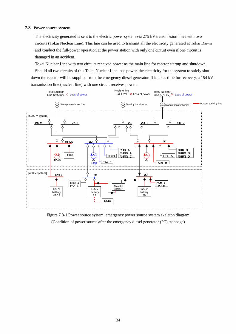
34
7.3 Power source system
The electricity generated is sent to the electric power system via 275 kV transmission lines with two circuits (Tokai Nuclear Line). This line can be used to transmit all the electricity generated at Tokai Dai-ni and conduct the full-power operation at the power station with only one circuit even if one circuit is damaged in an accident.
Tokai Nuclear Line with two circuits received power as the main line for reactor startup and shutdown. Should all two circuits of this Tokai Nuclear Line lose power, the electricity for the system to safely shut
down the reactor will be supplied from the emergency diesel generator. If it takes time for recovery, a 154 kV transmission line (nuclear line) with one circuit receives power.
Figure 7.3-1 Power source system, emergency power source system skeleton diagram
(Condition of power source after the emergency diesel generator (2C) stoppage)
Tokai Nuclear Line (275 kV) Loss of power
Nuclear line (154 kV) Loss of power
Tokai Nuclear Line (275 kV) Loss of power
Startup transformer 2 A Startup transformer 2B Power-receiving bus Standby transformer
[6900 V system]
[480 V system]
Stop
125 V battery HPCS
125 V battery
2A
Standby charger 125 V
battery 2B
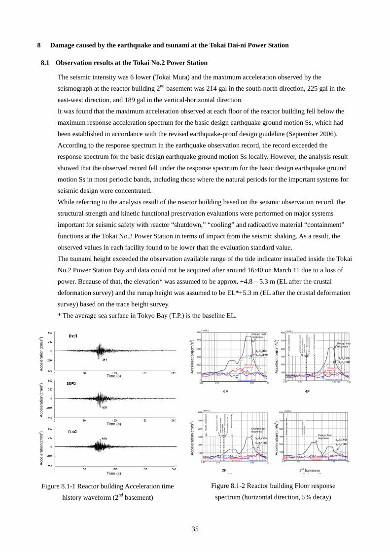
35
8 Damage caused by the earthquake and tsunami at the Tokai Dai-ni Power Station
8.1 Observation results at the Tokai No.2 Power Station
The seismic intensity was 6 lower (Tokai Mura) and the maximum acceleration observed by the seismograph at the reactor building 2nd basement was 214 gal in the south-north direction, 225 gal in the
east-west direction, and 189 gal in the vertical-horizontal direction. It was found that the maximum acceleration observed at each floor of the reactor building fell below the maximum response acceleration spectrum for the basic design earthquake ground motion Ss, which had been established in accordance with the revised earthquake-proof design guideline (September 2006). According to the response spectrum in the earthquake observation record, the record exceeded the response spectrum for the basic design earthquake ground motion Ss locally. However, the analysis result
showed that the observed record fell under the response spectrum for the basic design earthquake ground motion Ss in most periodic bands, including those where the natural periods for the important systems for seismic design were concentrated. While referring to the analysis result of the reactor building based on the seismic observation record, the structural strength and kinetic functional preservation evaluations were performed on major systems important for seismic safety with reactor “shutdown,” “cooling” and radioactive material “containment”
functions at the Tokai No.2 Power Station in terms of impact from the seismic shaking. As a result, the observed values in each facility found to be lower than the evaluation standard value. The tsunami height exceeded the observation available range of the tide indicator installed inside the Tokai No.2 Power Station Bay and data could not be acquired after around 16:40 on March 11 due to a loss of power. Because of that, the elevation* was assumed to be approx. +4.8 – 5.3 m (EL after the crustal deformation survey) and the runup height was assumed to be EL*+5.3 m (EL after the crustal deformation
survey) based on the trace height survey. * The average sea surface in Tokyo Bay (T.P.) is the baseline EL.
Acce
lera
tion(
cm/s
2 ) Ac
cele
ratio
n(cm
/s2 )
Acce
lera
tion(
cm/s
2 )
Time (s)
Time (s)
Time (s)
Acce
lera
tion(
cm/s
2 ) Ac
cele
ratio
n(cm
/s2 )
Acce
lera
tion(
cm/s
2 ) Ac
cele
ratio
n(cm
/s2 )
Design floor response
Design floor response
Design floor response
Design floor response
Observation record NS Observation
record NS
Observation record NS
Observation record NS
6F 4F
2F
Rea
ctor
con
tain
men
t
Rea
ctor
pre
ssur
e ve
ssel
Res
idua
l hea
t rem
oval
sy
stem
pip
ing
Mai
n st
eam
pip
ing
Con
trol r
od in
serta
bility
Cor
e su
ppor
t stru
ctur
e
Rea
ctor
con
tain
men
t
Rea
ctor
pre
ssur
e ve
ssel
Res
idua
l hea
t rem
oval
sy
stem
pip
ing
Con
trol r
od in
serta
bility
Cor
e su
ppor
t stru
ctur
e M
ain
stea
m p
ipin
g
Observation record EW Observation record EW
Observation record EW Observation record EW
Rea
ctor
con
tain
men
t
Res
idua
l hea
t rem
oval
sy
stem
pip
ing
Figure 8.1-1 Reactor building Acceleration time history waveform (2nd basement)
Figure 8.1-2 Reactor building Floor response spectrum (horizontal direction, 5% decay)
2nd basement
36
8.2 Damage and impact from the earthquake
Right after the earthquake, three circuits of the off-site power source (275 kV and 154 kV) were lost. Because of that, three emergency diesel generators (2C, 2D, HPCS) were automatically activated and supplied power to the emergency power buses. Vibration of the turbine bearings increased, affected by the earthquake, and the turbine generator automatically stopped with the signal of “turbine bearings vibration large,” resulting in an automatic reactor shutdown. At the laboratory sump within the service building, the electromagnetic valve for the sump pump seal water closed due to a blackout of the normal power caused by a loss of the off-site power source. Then, seal water continued to flow into the pertinent sump and the rubber stop that blocked the pertinent funnel was removed. As a result, flooding through the floor drain funnel occurred in the battery room of the combination structure 1F because there was a little difference in the height of the head with the pertinent sump. Leaked water was discharged to the emergency diesel generator room roof (outdoor) to protect the batteries. At the spent fuel pool, the spent fuel pool water alarm (“FUEL POOL LEVEL HI/LO”) was generated by sloshing due to the earthquake and the pool surroundings were flooded, causing the water level to decrease by approx. 20 cm from the normal level. Therefore, the spent fuel pool was refilled by using condensate storage tank water. Though the water level dropped, the spent fuel rods stored in the spent fuel pool were still fully flooded (fuel top + approx. 7 m). The spent fuel pool cooling & filtering system stopped due to a loss of the off-site power source; however, it resumed cooling with power received from the intact emergency diesel generator (2D).
8.3 Damage caused by tsunami
According to the result of checking the water trace and such like in an on-site survey, the tsunami runup height at Tokai Dai-ni was assumed to be approx. EL*+5.3 m (EL after crustal deformation) and it did not reach major buildings because it did not exceed the site elevation at Tokai No.2 (EL*+8.0 m (EL before the earthquake). Though tsunami reached around the seawater pump room at the seaside of the site (EL*+3.3m (EL before the earthquake)), inundation from above did not occur because of the side wall with EL*+6.1m (EL before the earthquake) installed in the seawater pump rooms on the north/south sides with EL*+ Approx. 5.7m (EL before the earthquake) as tsunami measures. However, seawater inundation occurred in the north-side pump room from the following two points where construction for waterproof had not been completed. (1) Openings between the north-side pump room and ASW strainer area (discharge channel) (2) Non-sealed structure of cable pit
* The average sea surface in Tokyo Bay (T.P.) is the baseline (ground subsidence due to crustal deformation was not taken into consideration).
Construction for waterproof completed at the south-side pump room. The emergency diesel generator seawater pump (2C) stopped due to seawater that had entered the north-side pump room caused by the tsunami. Because of that, the emergency diesel generator (2C) became inoperable and the emergency AC power bus 2C lost its power. Power for the emergency AC power bus 2D and HPCS bus was continuously secured, making it possible to maintain power supply to emergency equipment. At the inundated north-side pump room, the residual heat removal seawater pumps (A), (C) and component cooling seawater pumps (A), (C) were installed in addition to the emergency diesel generator seawater pump (2C) and these seawater pumps were flooded to the lower part of generators but there was
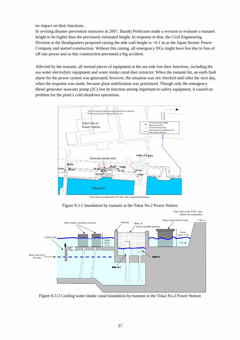
37
no impact on their functions. In revising disaster prevention measures in 2007, Ibaraki Prefecture made a revision to evaluate a tsunami height to be higher than the previously estimated height. In response to that, the Civil Engineering Division at the Headquarters proposed raising the side wall height to +6.1 m as the Japan Atomic Power Company and started construction. Without this raising, all emergency DGs might have lost due to loss of off-site power and so this construction prevented a big accident. Affected by the tsunami, all normal pieces of equipment at the sea side lost their functions, including the sea water electrolytic equipment and water intake canal dust extractor. When the tsunami hit, an earth fault alarm for the power system was generated; however, the situation was not checked until after the next day, when the response was made, because plant stabilization was prioritized. Though only the emergency diesel generator seawater pump (2C) lost its function among important-to-safety equipment, it caused no problem for the plant’s cold shutdown operations.
Figure 8.3-1 Inundation by tsunami at the Tokai No.2 Power Station
Figure 8.3-2 Cooling water intake canal inundation by tsunami at the Tokai No.2 Power Station
Trace of tsunami height and range of tsunami recognition in the Tokai Dai-ni Power Station site
Tokai Dai-ni Power Station
Trace of tsunami height observation point Tsunami runup range Site boundary (including site of Tokai Power Station)
Seawater pump area
Tokai Port
*All values are indicated in EL (EL after crustal deformation)
Water intake canal dust extractor
Curtain wall
Base water level TP 0.0m
Height approx. 2.8 m
Newly installed partition
Note: This is the TP:EL value (before the earthquake)
Water intake electric room
Height approx. 4.0 m
38
9 Responses to the earthquake disaster at the Tokai No.2 Power Station
9.1 Overview of responses right after the earthquake and tsunami for recovery and cold shutdown
The earthquake occurred at 14:48 on March 11 at the Tokai No.2 while it was in constant-rated thermal power output operation, and the turbine generator automatically stopped because of a signal announcing “turbine bearings vibration high,” resulting in an automatic reactor shutdown. Immediately after the earthquake, all three circuits of the off-site power source were lost; however, the power to the emergency equipment was secured as three emergency diesel generators activated. Immediately after the automatic reactor shutdown, the reactor water level was maintained at a normal level by the reactor core isolation cooling system and high-pressure core spray system while the reactor pressure was controlled by the main steam relief valve. Decay heat generated after the reactor shutdown was removed through suppression pool cooling by the residual heat removal system. After that, the emergency diesel generator seawater pump (2C) automatically stopped because of the tsunami, making the emergency diesel generator (2C) inoperable. However, the emergency power was secured by the two other emergency diesel generators without any effect on the reactor and spent fuel pool cooling function, resulting in a reactor cold shutdown at 00:40 on March 15.
9.2 Situation of the earthquake disaster responses
9.2.1 Immediately after the earthquake occurred
As the turbine generator automatically stopped, resulting in the reactor automatic stoppage because of the earthquake, the main control room made a notification to all buildings via paging. However, most of the employees did not understand the meaning of the notification because they were confused by the earthquake’s shaking. As the generated power indicator at the office showed zero, a power generation stop was confirmed, and then the organization shifted to a normal trouble state. Ultimately, the organization did not enter an emergency state or acute state, and the plant was brought to a cold shutdown under a normal trouble state (that is, a state where the chief of the regular operation line perform operations within the range of his or her responsibility). After receiving the first notification, the Headquarters launched the Emergency Response Center with the President as the head and established a system to provide the necessary support, based on plant information. At first, the plant personnel moved to an important anti-seismic building in order to avoid being harmed by a large aftershock. However, construction of this building was planned to be completed at the end of March and there were no pieces of communication equipment or image systems and such like. Therefore, the plant personnel returned to the Emergency Response Center on the 3F of the main building as the conventional direction center after waiting for 30 minutes until the earthquake finished. On March 11, the Site Superintendent was on a business trip for a meeting at the Headquarters. Because of that, an acting Site Superintendent took the lead in the earthquake response in accordance with the “Disaster Response Manual” until the Site Superintendent arrived at the power station via the Joban Expressway with a patrol car as an escort. As for coordination with the nuclear-related facilities in the Tokai area, arrangement of materials and equipment and personnel is made for an emergency based on “Tokai NOAH Arrangement.” However, responses within the power station were sufficient without entering an emergency state. Though three off-site power source systems of TEPCO’s substation side were lost in the event of the earthquake, three emergency diesel generators (2C, 2D, HPCS) automatically activated to supply power to the emergency power buses. Owing to this, lighting in the main office remained lost. On the other hand, lighting, communication systems and systems to monitor the plant status were usable in the Emergency Response Direction Center at the main building because it received power from the emergency power source. In addition, functions of the paging system were maintained by power received from the
39
emergency power source. Communication among the Emergency Response Center, Headquarters, and main control room was made via PHS and mobile phone. Mobile phones were effective as they were registered as a priority line in the event of a disaster. Furthermore, major operation parameters were displayed by CRT for information sharing at the Emergency Response Center while a TV conference system was used for information sharing. The TV conference system was frequently shut down because of possible problems with the telecommunications carrier. In addition, information from operators dispatched to the main control room was written on a whiteboard for information sharing. The Chief Engineer of Reactors made notifications to the President, and was engaged in examining countermeasures as an assistant of the Site Superintendent at the Emergency Response Center after checking the plant’s condition and initial response in the main control room. In line with the water level fluctuation (lowering) after the reactor shutdown, the high-pressure core spray system and reactor core isolation cooling system, which are part of the emergency core cooling system, automatically activated. Water injection function to the reactor under high-pressure was secured and so was a sufficient reactor water level. After that, the reactor water level was maintained by the reactor core isolation cooling system (the water source was the condensate storage tank initially and then the suppression pool) and the reactor pressure was controlled by opening and closing the main steam relief valve. Since the containment isolation system activated normally, caused by the water level fluctuation (lowering) after the automatic reactor shutdown, the containment was isolated. Similarly, the reactor building was automatically isolated by the water level fluctuation (lowering) just after the automatic reactor shutdown. The reactor building ventilation system was switched to the standby gas recirculation system/standby gas treatment system from the regular ventilation system in a normal way. Procedures specified the need to dispatch the proper number of contact persons to support operators in the main control room. A few operation support group members and such like present at the office went to the main control room to offer support. Immediately after the earthquake, many alarms were activated simultaneously in the main control room, and so each alarm was verified to see which was correct and which had been affected by the shaking. Tying lighting louvers (hang ceilings) to each other was effective to prevent them from falling in the main control room as earthquake measures. There were no injured persons because there were tip-resistant lockers and such like, and equipment had been tied down and fixed by anchor bolts. Notification of the automatic reactor shutdown to the government and local government was made by fax via simultaneous notification in accordance with the predetermined method after the earthquake and immediate aftershock. Then, notifications to the government and local government were made as needed. The Nuclear Safety Inspector came to the Emergency Response Center immediately after the earthquake and checked the information as needed. A device to control access to the radiation controlled area received power from the normal power source and input was manually made because of a loss of functions. In addition, mobile dosimeters were unavailable due to dead batteries, and dry-cell batteries were used until temporary power was secured. A contamination inspection was also performed manually due to loss of a contamination monitor function.
40
9.2.2 Immediately after the tsunami arrived
While acquiring information via one-segment broadcasting on a mobile phone after the earthquake, a tsunami warning was issued and people were instructed to evacuate to high ground in the entire power station. A direction was given for subcontractors through the contact route of the General Affairs system. Personnel were allocated to the important anti-seismic building and main building roof to serve as watchmen. As the tsunami alarm had not been cleared, no patrol personnel were sent to secure safety until the situation was under control, except for an operator patrol only in the buildings where the earthquake had an intensity of 4 or higher. Personnel present at the Emergency Response Center could not recognize that a tsunami had hit in real time because the normal power source was used for cameras which made it possible to monitor the water intake canal from the main control room. On the other hand, the fact that the tsunami had hit could be checked later from a recorded image as the camera for monitoring used a different power source and received power. The main control room performed monitoring with a tide indicator; however, it went down in the tsunami after the first large wave was observed. In addition, the main control room was monitoring discharge pressure to check the seawater pump condition. The emergency diesel generator seawater pump (2C) stopped because of seawater inundation in the north-side pump room, caused by the tsunami. Because of that, the emergency diesel generator (2C) became inoperable and the emergency AC power bus 2C lost power. Power for the emergency AC power bus 2D and high-pressure core spray system was continuously secured, maintaining power for the emergency equipment. Moreover, the emergency DC power supplied power to batteries via the emergency power bus and to AC power loading. DC power, which connects to the emergency AC power bus 2C, never lost power because the plant switched to the intact emergency AC power bus for charging batteries. Thus the DC power source was never lost. The residual heat removal system (B) was manually activated to remove decay heat after the automatic reactor shutdown and it started suppression pool cooling. While checking the flooding condition caused by sloshing of the spent fuel pool, a situational check was performed in line with the fire alarm. However, patrol of the plant system to check for damage was performed after the plant shutdown operations had been stabilized to some extent.
9.2.3 Plant responses after the tsunami arrived at the plant
(1) Operations and actions for plant stabilization Operations to shut down the reactor were as described in the normal manual on loss of off-site power as power was supplied from the emergency diesel generator. Because of that, the situation did not require a special response. Thus, operations and actions were taken under the judgment of the main control room without any special directions from the Headquarters. The Headquarters was especially monitoring “reactor water level, pressure, temperature,” “containment pressure, temperature,” “suppression chamber pressure, and water level, temperature” and “environment radiation monitor values.” The pressure at the suppression chamber just increased up to 102 kPaabs, resulting in no emergency situation at the plant. However, only one train of cooling system B was available and it was necessary to suspend the system in order to switch the residual heat removal system, for suppression pool cooling, to core cooling. As cooling systems would be lost if this switching failed, reactor cooling was initiated by switching system A to reactor shutdown cooling mode after waiting for the off-site power source and system A to be recovered and two trains to become operable in the afternoon on March 13. For the off-site power, 154 kV was recovered on March 13, one circuit of 275 kV on March 17 and one circuit of 275 kV line on April 27 because TEPCO prioritized recovery of nuclear lines. Consequently, all of the off-site power was recovered. One train of the emergency diesel generator was unavailable until the off-site power was recovered; thus, preparations were made by assuming that the operating emergency
41
diesel generator may stop due to a failure and such like. The PHS devices were of a charging type and normal power sources lost power. Therefore, PHS devices ran out of batteries in 1 hour at the earliest, causing inconvenience in communication with the local site. Paging and mobile phones were used. Plant personnel accessed and checked the seawater pump area as the night came. One patroller team consisting of four people checked the seawater pump area with transceivers and life jackets after making an opening in the water intake canal area fence so that they could evacuate should a tsunami hit. Lubricating water leaked from the glands of the seawater pump and produced a pool since power for the drain pump power installed in the pertinent area was normal system and water discharge was unavailable. For discharging, a second team was dispatched after dawn and it discharged the water by putting an engine-driven water pump into the pool. As for the temporary power source, the Emergency Response Center summarized the necessary power source applied from each division and made arrangements for construction based on an order of priorities. Half of the operators were subcontractors and half were direct-managed personnel. Any lacking cables and tools were transported from a subcontractor’s warehouses. Before construction, simple drawings and procedures that reflected system configurations and results of an on-site check were developed.
(2) Arrangement of personnel and materials and equipment
From March 11 to the next day, all plant personnel went on duty, and after the second day a 2-shift system (12–24 hour-shift) was implemented per room. In the main control room, two people in charge were allocated to each panel and they transferred and were replaced with two people. The subcontractor was asked to secure the necessary personnel based on the workload assumed by the maintenance staff. Especially, the subcontractor was asked to secure more personnel for electrical operations. Since the power source for the pump, which sends suppression pool water to the radioactive waste (liquid) disposal system, was a normal system, a gas turbine generator installed in the important anti-seismic building was used to supply power, since the Headquarters had said this was advisable. Power-supply vehicles were used to secure power around the main building. Some power supply vehicles were provided by Chubu Electric Power Company, Incorporated with fuel. One week’s worth of light oil was in stock but the Headquarters arranged for additional oil. Gasoline as a means of powering transportation could not be procured, and the plant gave up on trying to secure it. In addition, a tanker was arranged as an emergency source of fresh water. Radiation control materials and equipment were sufficient, causing no trouble. Three days’ worth of food was stocked as emergency food. After March 12, the subcontractor running the eatery delivered rice balls and the Headquarters and Tsuruga Power Station also gave support. The Headquarters proposed goods that might be required in the site and arranged for them in response to requests from the power station. For transporting food and materials and equipment, an application for an “emergency vehicle pass” was submitted to the responsible police office so that the emergency vehicle could drive along roads with traffic regulations on a priority basis. To carry out actions in the main building that had lost power, temporary lighting was effective. There were no injuries requiring a special medical team, and the permanently installed health management room was used for short sleeps and such like.
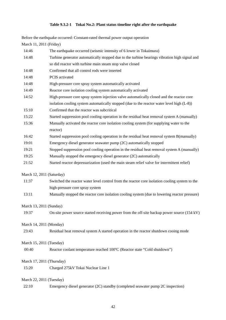
42
Table 9.3.2-1 Tokai No.2: Plant status timeline right after the earthquake Before the earthquake occurred: Constant-rated thermal power output operation March 11, 2011 (Friday)
14:46 14:48
14:48 14:48 14:48 14:49 14:52
15:10 15:22 15:36 16:42 19:01
19:21 19:25 21:52
The earthquake occurred (seismic intensity of 6 lower in Tokaimura) Turbine generator automatically stopped due to the turbine bearings vibration high signal and so did reactor with turbine main steam stop valve closed
Confirmed that all control rods were inserted PCIS activated High-pressure core spray system automatically activated Reactor core isolation cooling system automatically activated High-pressure core spray system injection valve automatically closed and the reactor core isolation cooling system automatically stopped (due to the reactor water level high (L-8))
Confirmed that the reactor was subcritical Started suppression pool cooling operation in the residual heat removal system A (manually) Manually activated the reactor core isolation cooling system (for supplying water to the reactor) Started suppression pool cooling operation in the residual heat removal system B(manually) Emergency diesel generator seawater pump (2C) automatically stopped
Stopped suppression pool cooling operation in the residual heat removal system A (manually) Manually stopped the emergency diesel generator (2C) automatically Started reactor depressurization (used the main steam relief valve for intermittent relief)
March 12, 2011 (Saturday)
11:37
13:11
Switched the reactor water level control from the reactor core isolation cooling system to the high-pressure core spray system
Manually stopped the reactor core isolation cooling system (due to lowering reactor pressure) March 13, 2011 (Sunday)
19:37 On-site power source started receiving power from the off-site backup power source (154 kV) March 14, 2011 (Monday)
23:43 Residual heat removal system A started operation in the reactor shutdown cooing mode March 15, 2011 (Tuesday)
00:40 Reactor coolant temperature reached 100ºC (Reactor state “Cold shutdown”) March 17, 2011 (Thursday)
15:20 Charged 275kV Tokai Nuclear Line 1 March 22, 2011 (Tuesday)
22:10 Emergency diesel generator (2C) standby (completed seawater pump 2C inspection)

43
April 27, 2011 (Wednesday)
16:29 Charged 275 kV Tokai Nuclear Line 2
44
10 Lessons learned from earthquake disaster responses at the Tokai No.2 Nuclear Power Station
Based on the earthquake response at Tokai No.2, it seems there are items that may be able to reduce operator burden at the site with some improvement, as well as items for which more effective measures may be taken by implementing the same measures at other power stations as good practice. These items are summarized below.
10.1 Organization, management, communication
• It is necessary to predetermine the communication system with subcontractors for an emergency and establish a response system once an emergency happens. Utilizing this system, information should be shared sufficiently.
• The Site Superintendent was absent when the earthquake and tsunami occurred and an acting Site Superintendent took the lead in handling the accident. The acting Site Superintendent could properly handle the situation because the emergency response exercises were conducted on a daily basis with participation of all the management members.
• An internal system and way of coordinating with the mass media and local government should be arranged beforehand to distribute information to the local area and multiple methods should be prepared for notification.
• For sharing information between the Emergency Response Center and main control room, the Emergency Response Center should be able to monitor the process computer, local monitoring camera (ITV) and tide gauge indications. Using a TV conference system is also effective. In addition, a method to acquire information from external bodies (TV and radio) should be prepared.
10.2 Preparedness (system, manual, training)
• Plant workers who are not required for the accident response should be evacuated. An evacuation route, method and place shall be predetermined and fully notified to workers on a routine basis. When evacuating from the controlled area, evacuation should be prioritized and a contamination inspection should be performed at the evacuation area. Paging is effective as a method to notify people of a situation that requires evacuation and a beeping sound should be clear so as to notify people of an emergency. Furthermore, preparations should be needed through exercises as needed to ensure evacuation. In addition, preparations should be made for emergency evacuation guidance for visitors at the power station facility.
• The management should secure lines of communication with subordinates for an emergency. E-mail is effective and a way to confirm safety should be determined beforehand.
• An immediate installation of a temporary power source can be possible by organizing a number of backup cables, specifications, storage locations, clarifying the storage location of related materials and equipment, amount and pre-check method, developing lists of equipment power source, MCC unit list (specifications of built-in equipment such as NFB) and storing the latest paper-based drawings (CWD and such like) near the local site. Moreover, it is effective to deploy mobile engine generators in groups of different voltages and capacities.
• Three days’ worth of water and food were stocked for disaster response personnel for an emergency. However, more personnel were engaged than expected as the earthquake and tsunami hit in the evening on a weekday. Moreover, those who could not return to their home stayed at the power station. Thus, there was insufficient water and food. Because of that, supplies were transported from the Headquarters (Tokyo) and Tsuruga for replenishment. Considering operators from subcontractors, water and food for 2,000 to 3,000 people should be secured and a replenishment method should be prepared beforehand.
• As the emergency diesel generator and power source vehicles consume a large amount of fuel during their continuous operation, their usage should be determined beforehand and a fuel stocking and replenishment method should be prepared in line with their usage. It is necessary to stock fuel in a location that will not be affected by a tsunami.
45
• It is recommended to make a list of supplies that are required if the emergency situation is prolonged and to replenish supplies immediately through information sharing with the Headquarters. The same applies to logistical matters such as temporary lavatories.
• It is recommended to take full tip-resistant and anti-drop measures for supplies in the event of an earthquake.
10.3 Initial responses in the event of an earthquake
• A team should be organized to dispatch operators to the site for duties such as patrol and it is necessary to pay attention so that operator does not act alone in terms of safety.
• Each personnel member should prepare supplies required for the emergency, such as helmets and flashlights as much as possible.
• Developing procedures and sharing information beforehand is essential for smooth and reliable operations even in a situation requiring urgent action.
• For contact to the main control room from the site, information management for the specific contact person makes it possible to avoid conflicting information. It is recommended to ensure this through exercises beforehand.
• When working in an area where operators cannot hear a pager or check the sea condition, such as the seawater pump room, allocating an exclusive observer is recommended to secure the safety of operators, not just by preparing a mobile phone constantly.
10.4 Additional measures
• Through a follow-up of a revision to the disaster prevention plan carried out by the local government, raising the side wall in the seawater pump area resulted in securing power and settling the situation without it escalating into an accident. It is an example that shows the importance of taking safety measures in a timely manner without hesitation.
• During recovery operation after the earthquake, thorough information sharing among the parties concerned is required in the morning and at meetings for smooth operations.
• It is recommended to make preparations to receive power from emergency power sources and batteries so as to enhance the reliability of communication systems. In addition, diversification of communication lines such as by using a satellite line for a TV conference system is desirable. Lines of communication should also be diversified by utilizing wired land phones, charging-type simple telephone devices, radios and transceivers and such like. Moreover, mobile phones should be registered for the disaster priority line. Information sharing is easy with a telephone with a speakerphone function.
• It is recommended to make arrangement so that a radiation control calculator, weather observation device, and local monitoring camera necessary for disaster measures can receive power from an emergency power source with redundancy as much as possible.
• Preparations should be made to develop a list of instruments required for monitoring in an emergency in the main control room and to connect power sources such as batteries immediately.
• Reuse of PHS antennas is impossible if they are inundated; therefore, reserving backup antennas is required. Moreover, the locations of antennas should be decided in light of the impact of an earthquake and tsunami.

46
11 Conclusion
Currently, 49 nuclear power plants in Japan have been shut down except Ooi Units 3 & 4. In July 2013, the Nuclear Regulation Authority promulgated new technical standards and a plant re-startup is now possible only after confirming whether important-to-safety measures are appropriately taken. However, such efforts of the Nuclear Regulation Authority only are not enough to overcome the public’s distrust in nuclear safety and it may be necessary for electric companies to show their attitude to address safety enhancement over the long term. In conjunction with proficiency in accident response through training, it is necessary to combine measures in hardware (e.g., system expansion to prevent accident spreading) and software (e.g., developing a response manual in accordance with the accident condition) and continuously promote activities to cultivate a safety culture that does not degrade as time passes. The Japan Nuclear Safety Institute hopes this report will serves as an aid in the activities of electric power companies.