response to accidents at sea involving spills of hazardous ... manual on co-operation in... · the...
TRANSCRIPT
HELCOM Manual on Co-operation in Response to Marine Pollution within the framework of the Convention on the Protection of the Marine Environment of the Baltic Sea Area (Helsinki Convention), Volume 2, 1 December 2002
Contents-1
Response to accidents at sea involving spills of hazardous substances and loss of packaged dangerous goods
Table of Contents
Chapter 1 Introduction 1.1 Purpose and scope 1.2 General first response to chemical accidents 1.3 Behaviour of chemicals 1.4 Selection of response measures with regard to physical properties 1.5 Information sheets 1.6 Manuals and handbooks on response to maritime accidents
involving chemicals and dangerous goods
Chapter 2 Predicting the drift and spread of chemical spills 2.1 Introduction 2.2 Gas clouds 2.3 Floating spills 2.4 Dissolved spills in the water body 2.5 Sinking spills 2.6 Forecasting modelling systems
Chapter 3 Monitoring and body protection
3.1 Gas monitoring by portable instruments 3.2 Monitoring the water column 3.3 Monitoring surface spills 3.4 Monitoring sunken substances on the seabed 3.5 Miscellaneous monitoring methods 3.6 Levels of body protection during chemical accidents
Chapter 4 Sampling
4.1 General 4.2 Sampling chemical spills on the water surface 4.3 Sampling chemical spills in the water column 4.4 Taking samples from sunken chemicals 4.5 Taking samples on beaches and from smeared animals 4.6 Taking samples from packages 4.7 Taking samples on board vessels 4.8 Handling of samples 4.9 Example of a form for Request for Analysis
HELCOM Manual on Co-operation in Response to Marine Pollution within the framework of the Convention on the Protection of the Marine Environment of the Baltic Sea Area (Helsinki Convention), Volume 2, 1 December 2002
Contents-2
Chapter 5 Techniques for corrective response to accidents involving spills of hazardous substances in the marine environment
5.1 Gases and evaporators 5.2 Chemicals that float on the water surface 5.3 Chemicals that dissolve in water 5.4 Chemicals that sink to the bottom 5.5 Chemicals that react with water 5.6 Miscellaneous disposal methods
Chapter 6 Techniques for corrective response to accidents involving
lost packaged dangerous goods in the marine environment 6.1 Introduction 6.2 Examples of packagings and containers 6.3 Labelling and marking of dangerous goods 6.4 Behaviour of packages in seawater 6.5 Safety precautions 6.6 Salvage of floating packaged goods 6.7 Salvage operations involving sunken packaged goods 6.8 Packages washed ashore 6.9 Salvage of packages from sunken craft
6.10 Chemical warfare agents
Annex 1 First response actions in chemical accidents Annex 2 Chemical resistance of materials Annex 3 Case histories of marine chemical accidents Annex 4 Classification of chemical spills in water
and connection to related response methods Annex 5 Body protection levels Annex 6 International labelling of dangerous goods Annex 7 Conversion table for measurement units Annex 8 References

HELCOM Response Manual, Volume 2 Chapter 1 1 December 2002
1-1
1 Introduction 1.1 Purpose and scope International Maritime Organization IMO estimates that more than half of packaged goods and bulk cargoes transported by sea today can be regarded as dangerous, hazardous or harmful to the environment. A great deal of these substances, materials and articles are also dangerous or hazardous from a human safety point of view. The increasing trend in maritime transport of chemicals and dangerous goods also gives rise to an increasing number of accidents involving such products. This development makes great demands on the personnel who are responsible for actions against such accidents in order to protect man and environment from damage. The aim of this Manual is to provide information to support proper decisions when responding to accidents in the marine environment involving chemicals and dangerous goods. However, it is not possible to provide turn-key solutions ready to retrieve from the Manual on the scene of the accident. The contents of the Manual must be thoroughly reviewed beforehand and the contents are primarily aimed for personnel who are famil-iar with the area. The chapters of this Manual focus on spills and lost packages. Chapters 1 - 2 deal with spill behaviour and drift forecasting. Chapters 3 - 6 address monitoring, sampling and response. The Annexes 1 - 7 contain facts on first response, resistivity of materials, case histories, classification of spills, body protection, labelling, and measurement units. Annex 8 contains references. 1.2 General first response to chemical accidents Definition of response: The efforts to minimize the risks created in an emergency by protecting the people, the environment, and property, and the efforts to return the scene to normal pre-emergency conditions. Spills of chemicals at sea are rarely detected without notice in the same way as oil spills. They are most often involved in maritime accidents and can sometimes be ob-served, surveyed or monitored in the marine environment close to the site of the acci-dent. Unknown lost packages of dangerous goods are sometimes detected floating at sea or washed ashore. Most often, however, such packages can be connected with known accidents. Occurred accidents, and spills involving chemicals, as well as lost packages of danger-ous goods must be reported to all relevant bodies according to national and international agreements and regulations. When responding to accidents involving chemicals or dangerous goods some general first steps must often be taken which are the same for many accidents no matter what chemicals are involved or what the circumstances are (cf. Annex 1).
HELCOM Response Manual, Volume 2 Chapter 1 1 December 2002
1-2
Never rush into a chemical incident, but try to use your common sense and assess the situation carefully. Plan the work on a worst possible case basis. Realize that each chemical is different and that a new incident is not going to be the same as an earlier one. There is nothing like a typical incident. The following list of advices includes such general routines that often should be ap-plied. In minor incidents it is not necessary to follow some of the advices, or it is quite enough to limit their extent. At major accidents it might be necessary to apply the ad-vices to the fullest possible extent. See also “K. Example of a checklist” at the end of Annex 1. Get a rapid general view of the situation and judge the need for the most urgent
actions to be taken, such as medical care of victims, restriction of access, evacua-tion, reduction of leakages, etc.
Warn passers-by, seafarers, public, etc. Inform appropriate authorities, agencies and mass media.
Identify all involved chemicals. Note their mode of transport (bulk, container, palleted goods, etc.) as well as type of spill or discharge (escaped chemicals, lost packaged dangerous goods).
Judge the risk for fire, explosion, leakage as well as health risks and risks for adjacent areas (utilize e.g. the IMDG Code, Material Safety Data Sheets, Chemi-cal Safety Cards, Chemical Information Databases).
Establish restriction areas (risk zones) and restrict access to these areas by guard-ing the entrances.
Make preparations for procedures regarding decontamination, relieving and replacement of personnel, materials and equipment.
Make appropriate arrangements for beaches, swimming areas, fishing grounds, fresh water intakes, etc., such as restriction of access or restriction of right to use.
Use monitoring devices continuously for fire, explosion and health risks.
Assess emission rates, volumes, properties and reactivity for involved chemicals.
Assess initial drift, spread and evaporation (direction, distance, volumes) and calculate these behaviours by modelling programs and make forecast maps.
Continuously monitor drift and spread in order to assess the risk, and continu-ously take appropriate actions based on the judgements.
Take appropriate steps to stop or reduce damage to environment and property.
Contact, as soon as possible, relevant environmental bodies and plan for appropriate handling of the hazardous waste that the accident and the operation may yield.
HELCOM Response Manual, Volume 2 Chapter 1 1 December 2002
1-3
1.3 Behaviour of chemicals 1.3.1 General physical behaviour of released chemicals in water Certain general actions should always be taken when accidents involving chemicals and dangerous goods occur. These actions are often the same for most types of accidents, regardless of the circumstances and materials involved. When responding to a chemical spill in the aquatic environment, it is important that the measures are adjusted for the chemical’s physical behaviour in water. The patterns of spill behaviour in water of various chemical groups and packages are discussed in this Section. Figure 1 - 1 illustrates the principle ways of behaviour of chemicals when spilled into water. However, it should be stressed that this picture is simplified. A chemical spill may exhibit more than one of these properties at the same time. For example, it may float on the water surface and at the same time evaporate and/or dis-solve. It may also react with water. A graphical illustration of the system is given in Figure 1 - 2. The denominations (G, GD, E, etc.) in this figure are explained in subchap-ter 1.4 and in Annex 4.
Figure 1 - 1 Principal behaviours of chemicals when spilled into water.
Figure 1 - 2 Graphical illus-tration of the behaviours of chemicals and dangerous goods in water (the designa-tions G, GD, E, ED, etc. are further explained in Figure 1 - 12 below and in Annex 4).
HELCOM Response Manual, Volume 2 Chapter 1 1 December 2002
1-4
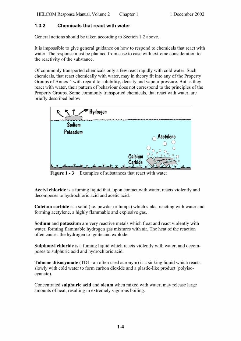
1.3.2 Chemicals that react with water General actions should be taken according to Section 1.2 above. It is impossible to give general guidance on how to respond to chemicals that react with water. The response must be planned from case to case with extreme consideration to the reactivity of the substance. Of commonly transported chemicals only a few react rapidly with cold water. Such chemicals, that react chemically with water, may in theory fit into any of the Property Groups of Annex 4 with regard to solubility, density and vapour pressure. But as they react with water, their pattern of behaviour does not correspond to the principles of the Property Groups. Some commonly transported chemicals, that react with water, are briefly described below.
Figure 1 - 3 Examples of substances that react with water Acetyl chloride is a fuming liquid that, upon contact with water, reacts violently and decomposes to hydrochloric acid and acetic acid. Calcium carbide is a solid (i.e. powder or lumps) which sinks, reacting with water and forming acetylene, a highly flammable and explosive gas. Sodium and potassium are very reactive metals which float and react violently with water, forming flammable hydrogen gas mixtures with air. The heat of the reaction often causes the hydrogen to ignite and explode. Sulphonyl chloride is a fuming liquid which reacts violently with water, and decom-poses to sulphuric acid and hydrochloric acid. Toluene diisocyanate (TDI - an often used acronym) is a sinking liquid which reacts slowly with cold water to form carbon dioxide and a plastic-like product (polyiso-cyanate). Concentrated sulphuric acid and oleum when mixed with water, may release large amounts of heat, resulting in extremely vigorous boiling.
HELCOM Response Manual, Volume 2 Chapter 1 1 December 2002
1-5
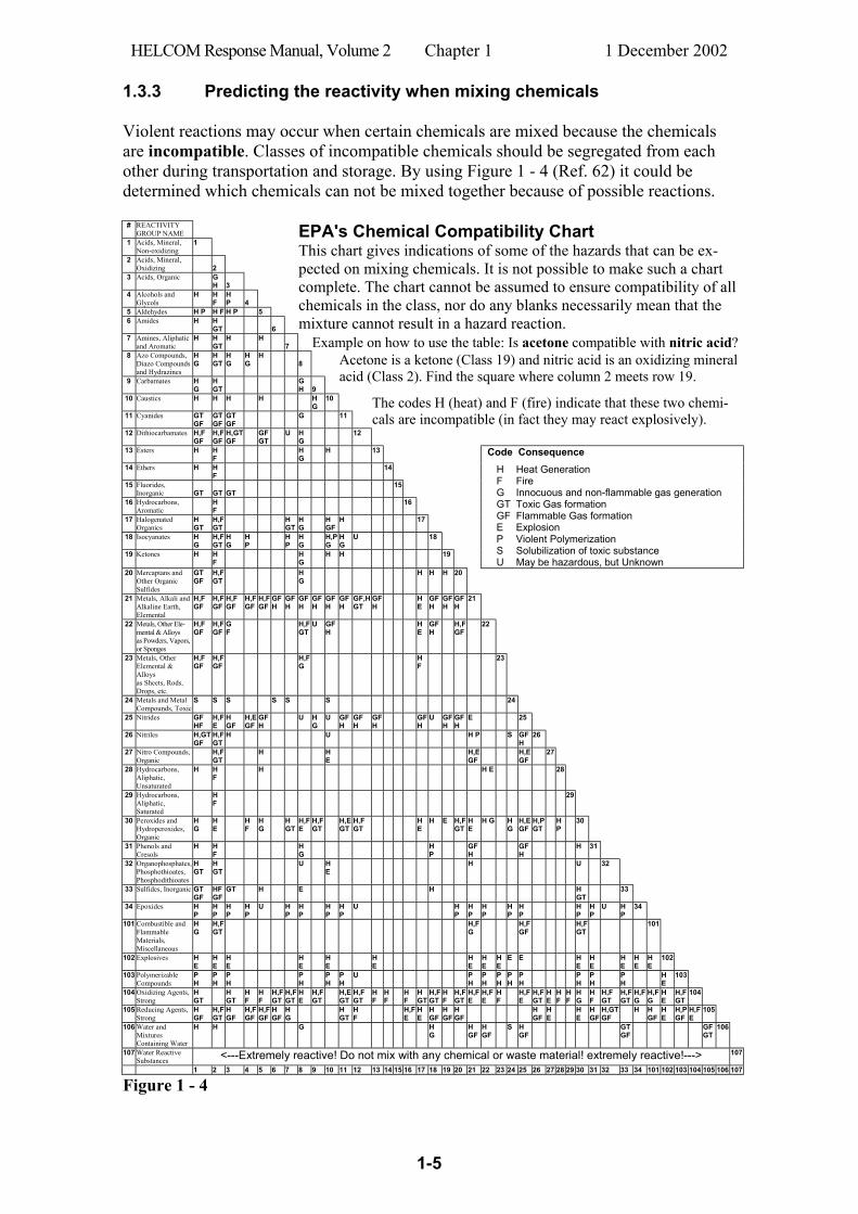
1.3.3 Predicting the reactivity when mixing chemicals Violent reactions may occur when certain chemicals are mixed because the chemicals are incompatible. Classes of incompatible chemicals should be segregated from each other during transportation and storage. By using Figure 1 - 4 (Ref. 62) it could be determined which chemicals can not be mixed together because of possible reactions.
# REACTIVITY GROUP NAME
1 Acids, Mineral, Non-oxidizing
1
2 Acids, Mineral, Oxidizing
2
3 Acids, Organic G H
3
4 Alcohols and Glycols
H H F
H P
4
5 Aldehydes H P H F H P 5 6 Amides H H
GT
6
EPA's Chemical Compatibility Chart This chart gives indications of some of the hazards that can be ex-pected on mixing chemicals. It is not possible to make such a chart complete. The chart cannot be assumed to ensure compatibility of all chemicals in the class, nor do any blanks necessarily mean that the mixture cannot result in a hazard reaction.
7 Amines, Aliphatic and Aromatic
H H GT
H H 7
Example on how to use the table: Is acetone compatible with nitric acid? 8 Azo Compounds,
Diazo Compounds and Hydrazines
H G
H GT
H G
H G
H 8
9 Carbamates H G
H GT
G H
9
Acetone is a ketone (Class 19) and nitric acid is an oxidizing mineral acid (Class 2). Find the square where column 2 meets row 19.
10 Caustics H H H H H G
10
11 Cyanides GT GF
GT GF
GT GF
G 11 The codes H (heat) and F (fire) indicate that these two chemi-cals are incompatible (in fact they may react explosively).
12 Dithiocarbamates H,F GF
H,F GF
H,GT GF
GF GT
U H G
12
13 Esters H H F
H G
H 13 Code Consequence
14 Ethers H H F
14
15 Fluorides, Inorganic
GT
GT
GT
15
16 Hydrocarbons, Aromatic
H F
16
17 Halogenated Organics
H GT
H,F GT
H GT
H G
H GF
H 17
18 Isocyanates H G
H,F GT
H G
H P
H P
H G
H,P G
H G
U 18
19 Ketones H H F
H G
H H 19
H Heat Generation F Fire G Innocuous and non-flammable gas generation GT Toxic Gas formation GF Flammable Gas formation E Explosion P Violent Polymerization S Solubilization of toxic substance U May be hazardous, but Unknown
20 Mercaptans and Other Organic Sulfides
GT GF
H,F GT
H G
H H H 20
21 Metals, Alkali and Alkaline Earth, Elemental
H,F GF
H,F GF
H,F GF
H,F GF
H,F GF
GF H
GF H
GF H
GF H
GF H
GF H
GF,H GT
GF H
H E
GF H
GF H
GF H
21
22 Metals, Other Ele-mental & Alloys as Powders, Vapors, or Sponges
H,F GF
H,F GF
G F
H,F GT
U GF H
H E
GF H
H,F GF
22
23 Metals, Other Elemental & Alloys as Sheets, Rods, Drops, etc.
H,F GF
H,F GF
H,F G
H F
23
24 Metals and Metal Compounds, Toxic
S S S S S S 24
25 Nitrides GF HF
H,F E
H GF
H,E GF
GF H
U H G
U GF H
GF H
GF H
GF H
U GF H
GF H
E 25
26 Nitriles H,GT GF
H,F GT
H U H P S GF H
26
27 Nitro Compounds, Organic
H,F GT
H H E
H,E GF
H,E GF
27
28 Hydrocarbons, Aliphatic, Unsaturated
H H F
H H E 28
29 Hydrocarbons, Aliphatic, Saturated
H F
29
30 Peroxides and Hydroperoxides, Organic
H G
H E
H F
H G
H GT
H,F E
H,F GT
H,E GT
H,F GT
H E
H E H,F GT
H E
H G H G
H,E GF
H,P GT
H P
30
31 Phenols and Cresols
H H F
H G
H P
GF H
GF H
H 31
32 Organophosphates, Phosphothioates, Phosphodithioates
H GT
H GT
U H E
H U 32
33 Sulfides, Inorganic GT GF
HF GF
GT H E H H GT
33
34 Epoxides H P
H P
H P
H P
U H P
H P
H P
H P
U H P
H P
H P
H P
H P
H P
H P
U H P
34
101 Combustible and Flammable Materials, Miscellaneous
H G
H,F GT
H,F G
H,F GF
H,F GT
101
102 Explosives H E
H E
H E
H E
H E
H E
H E
H E
H E
E E H E
H E
H E
H E
H E
102
103 Polymerizable Compounds
P H
P H
P H
P H
P H
P H
U P H
P H
P H
P H
P H
P H
P H
P H
H E
103
104 Oxidizing Agents, Strong
H GT
H GT
H F
H F
H,F GT
H,F GT
H E
H,F GT
H,E GT
H,F GT
H F
H F
H F
H GT
H,F GT
H F
H,F GT
H,F E
H,F E
H F
H,F E
H,F GT
H E
H F
H F
H G
H F
H,F GT
H,F GT
H,F G
H,F G
H E
H,F GT
104
105 Reducing Agents, Strong
H GF
H,F GT
H GF
H,F GF
H,F GF
H GF
H G
H GT
H F
H,F E
H E
H GF
H GF
H GF
H GF
H E
H E
H GF
H,GT GF
H
H GF
H E
H,P GF
H,F E
105
106 Water and Mixtures Containing Water
H H G H G
H GF
H GF
S H GF
GT GF
GF GT
106
107 Water Reactive Substances <---Extremely reactive! Do not mix with any chemical or waste material! extremely reactive!---> 107
1 2 3 4 5 6 7 8 9 10 11 12 13 14 15 16 17 18 19 20 21 22 23 24 25 26 27 28 29 30 31 32 33 34 101 102 103 104 105 106 107
Figure 1 - 4

HELCOM Response Manual, Volume 2 Chapter 1 1 December 2002
1-6
The Chemical Reactivity Worksheet The Chemical Reactivity Worksheet is a program that is used to find information about the potential reactivity of substances and mixtures of substances. The Worksheet was developed by the CAMEO Team at the Office of Response and Restoration, National Ocean Service, NOAA, and the Chemical Emergency Prevention and Preparedness Office of the Environmental Protection Agency, EPA. The program can be downloaded free from WWW (April 2002: http://response.restoration.noaa.gov/chemaids/react.html). Chemical Reactivity Worksheet includes a database of reactivity information for more than 6,000 common hazardous chemicals. The database includes information about the special hazards of each chemical and about whether a chemical reacts with air, water, or other materials.
Figure 1 - 5 The preliminary result is shown.
To use the Work-sheet, chemicals are selected from its database, and added to a "mixture"- like the chemicals in an accident - to find out what dangers could arise from accidental mixing. The Worksheet then predicts the reactiv-ity of this mixture. Figure 1 - 5 and Figure 1 - 6 show how the Chemical Reactivity Work-sheet is used to assess the reactivity of two substances “acetone” and “nitric acid”.
Figure 1 - 6 Three reactivity groups are shown with indication of the hazards of the mixture.
HELCOM Response Manual, Volume 2 Chapter 1 1 December 2002
1-7
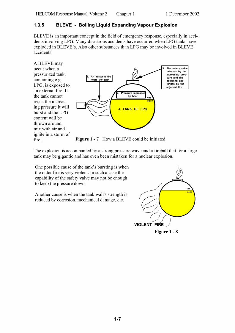
1.3.5 BLEVE - Boiling Liquid Expanding Vapour Explosion BLEVE is an important concept in the field of emergency response, especially in acci-dents involving LPG. Many disastrous accidents have occurred when LPG tanks have exploded in BLEVE’s. Also other substances than LPG may be involved in BLEVE accidents. A BLEVE may occur when a pressurized tank, containing e.g. LPG, is exposed to an external fire. If the tank cannot resist the increas-ing pressure it will burst and the LPG content will be thrown around, mix with air and ignite in a storm of fire.
Figure 1 - 7 How a BLEVE could be initiated
The explosion is accompanied by a strong pressure wave and a fireball that for a large tank may be gigantic and has even been mistaken for a nuclear explosion. One possible cause of the tank’s bursting is when the outer fire is very violent. In such a case the capability of the safety valve may not be enough to keep the pressure down. Another cause is when the tank wall's strength is reduced by corrosion, mechanical damage, etc.
Figure 1 - 8

HELCOM Response Manual, Volume 2 Chapter 1 1 December 2002
1-8
Figure 1 - 9 and Figure 1 - 10 show a typical development of a BLEVE when the fire softens the tank wall which then looses its strength and the tank ruptures.
Figure 1 - 9 Figure 1 - 10
The tank wall is first cooled by the liquefied LPG inside. The cooling effect disappears when the evaporation causes the liquid surface to lower. The steel wall looses its strength and ruptures and a BLEVE occurs. A BLEVE may occur in similar situations on board ships (cf. Figure 1 - 11). A re-sponse option on such an occasion is dousing with water from a safe distance. But evacuation should also be considered.
Figure 1 - 11
HELCOM Response Manual, Volume 2 Chapter 1 1 December 2002
1-9
1.4 Selection of response measures
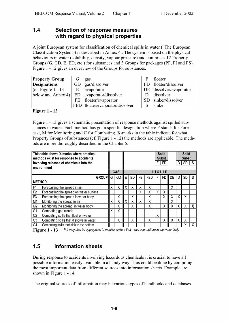
with regard to physical properties A joint European system for classification of chemical spills in water ("The European Classification System") is described in Annex 4.. The system is based on the physical behaviours in water (solubility, density, vapour pressure) and comprises 12 Property Groups (G, GD, E, ED, etc.) for substances and 3 Groups for packages (PF, PI and PS). Figure 1 - 12 gives an overview of the Groups for substances. Property Group G gas F floater Designations GD gas/dissolver FD floater/dissolver (cf. Figure 1 - 13 E evaporator DE dissolver/evaporator below and Annex 4) ED evaporator/dissolver D dissolver FE floater/evaporator SD sinker/dissolver FED floater/evaporator/dissolver S sinker Figure 1 - 12 Figure 1 - 13 gives a schematic presentation of response methods against spilled sub-stances in water. Each method has got a specific designation where F stands for Fore-cast, M for Monitoring and C for Combating. X-marks in the table indicate for what Property Groups of substances (cf. Figure 1 - 12) the methods are applicable. The meth-ods are more thoroughly described in the Chapter 5. This table shows X-marks where practical methods exist for response to accidents
Solid Subst
Solid Subst
involving releases of chemicals into the F FD D SD S environment GAS L I Q U I D
GROUP METHOD
G GD E ED FE FED F FD DE D SD S
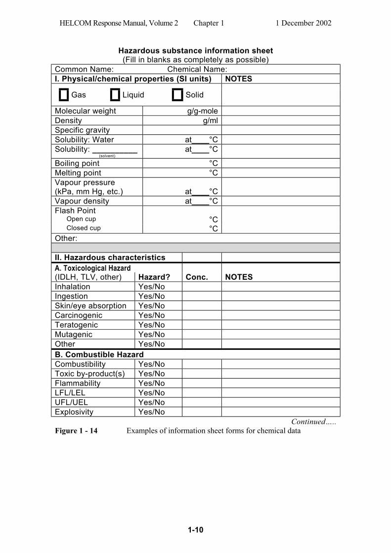
F1 Forecasting the spread in air X X X X X X X F2 Forecasting the spread on water surface X X X X F3 Forecasting the spread in water body X X X X X X X M1 Monitoring the spread in air X X X X X X X M2 Monitoring the spread in water body X X X X X X X 1) C1 Combating gas clouds X X C2 Combating spills that float on water X C3 Combating spills that dissolve in water X X X X X X X C4 Combating spills that sink to the bottom X X Figure 1 - 13 1) It may also be appropriate to monitor sinkers that move over bottom in the water body 1.5 Information sheets During response to accidents involving hazardous chemicals it is crucial to have all possible information easily available in a handy way. This could be done by compiling the most important data from different sources into information sheets. Example are shown in Figure 1 - 14. The original sources of information may be various types of handbooks and databases.
HELCOM Response Manual, Volume 2 Chapter 1 1 December 2002
1-10
Hazardous substance information sheet (Fill in blanks as completely as possible)
Common Name: Chemical Name: I. Physical/chemical properties (SI units) NOTES
Gas Liquid Solid
Molecular weight g/g-mole Density g/ml
Specific gravity Solubility: Water at____°C Solubility: __________ at____°C (solvent)
Boiling point °C Melting point °C Vapour pressure (kPa, mm Hg, etc.)
at____°C
Vapour density at____°C Flash Point Open cup °C Closed cup °C Other: II. Hazardous characteristics A. Toxicological Hazard (IDLH, TLV, other) Hazard? Conc. NOTES Inhalation Yes/No Ingestion Yes/No Skin/eye absorption Yes/No Carcinogenic Yes/No Teratogenic Yes/No Mutagenic Yes/No Other Yes/No B. Combustible Hazard Combustibility Yes/No Toxic by-product(s) Yes/No Flammability Yes/No LFL/LEL Yes/No UFL/UEL Yes/No Explosivity Yes/No
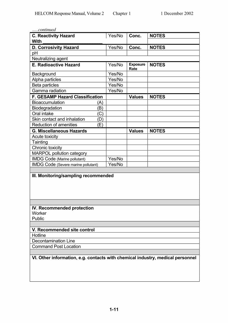
Continued….. Figure 1 - 14 Examples of information sheet forms for chemical data
HELCOM Response Manual, Volume 2 Chapter 1 1 December 2002
1-11
…..continued C. Reactivity Hazard Yes/No Conc. NOTES With ________________________ D. Corrosivity Hazard Yes/No Conc. NOTES pH Neutralizing agent E. Radioactive Hazard Yes/No Exposure
Rate NOTES
Background Yes/No Alpha particles Yes/No Beta particles Yes/No Gamma radiation Yes/No F. GESAMP Hazard Classification Values NOTES Bioaccumulation (A) Biodegradation (B) Oral intake (C) Skin contact and inhalation (D) Reduction of amenities (E) G. Miscellaneous Hazards Values NOTES Acute toxicity Tainting Chronic toxicity MARPOL pollution category IMDG Code (Marine pollutant) Yes/No IMDG Code (Severe marine pollutant) Yes/No III. Monitoring/sampling recommended IV. Recommended protection Worker Public V. Recommended site control Hotline Decontamination Line Command Post Location VI. Other information, e.g. contacts with chemical industry, medical personnel
HELCOM Response Manual, Volume 2 Chapter 1 1 December 2002
1-12
1.6 Manuals and handbooks on response to maritime
accidents involving chemicals and dangerous goods Very few manuals and handbooks in English specifically address the field of response to maritime accidents involving chemicals and dangerous goods. The following are examples of such publications: CHRIS Response Methods Handbook, US Coast Guard (Ref. 49) Containers and packages lost at sea - Operational Guide, CEDRE (Ref. 43) Manual on Chemical Pollution - Section 1&2, IMO (Ref. 1a and 1b) Practical Guide for Marine Chemical Spills, REMPEC (Ref. 3) The Swedish Coast Guard has elaborated an extensive handbook in Swedish (Ref. 2) containing 22 chapters with instructions for the organization’s personnel. Six of the chapters in this handbook contain detailed instructions on actions against maritime accidents involving chemicals and dangerous goods. These instructions are directed at the Response Commander, the On-Scene Commander (OSC), the chiefs of the Coast Guard Environmental Response vessels, and the field personnel.
HELCOM Response Manual, Volume 2 Chapter 2 1 December 2002
2-1
2 Predicting the drift and spread of chemical spills
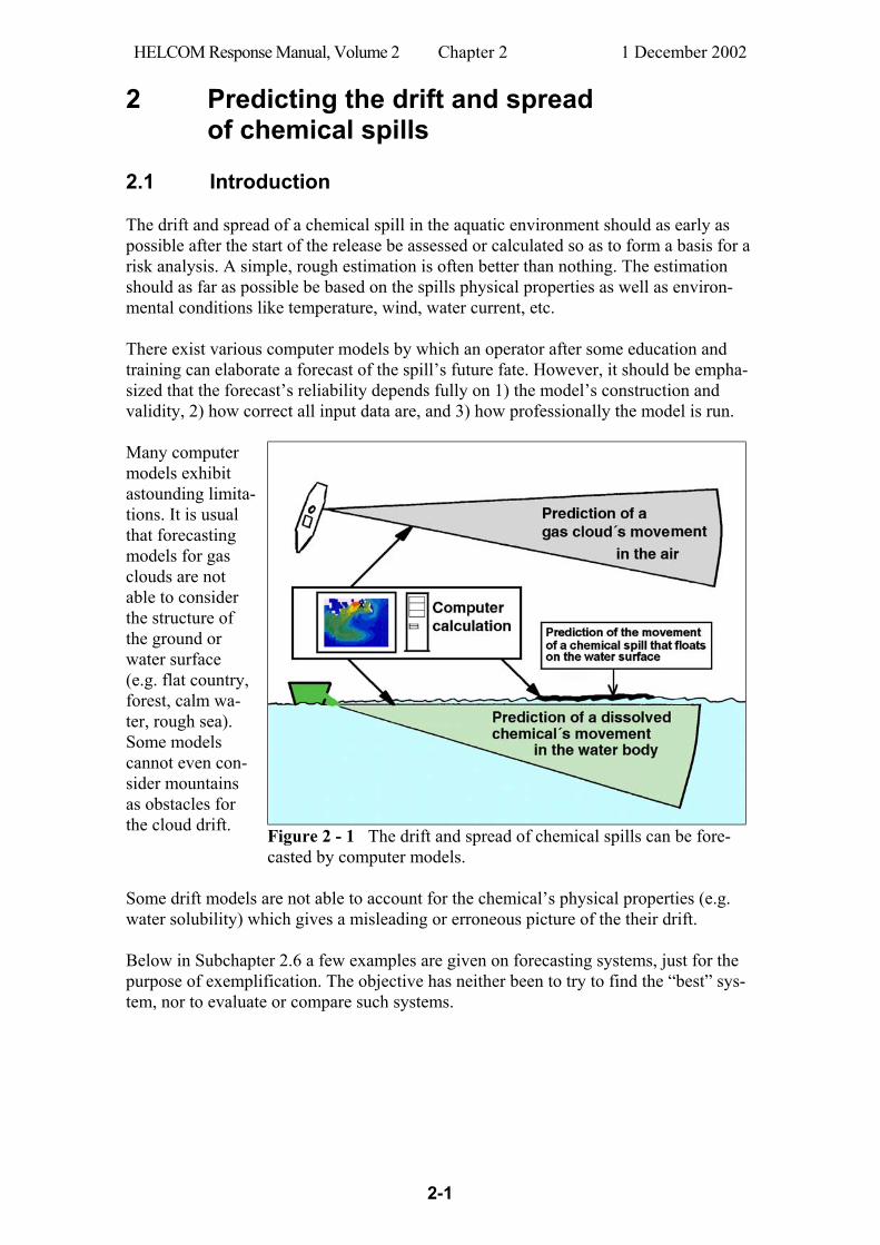
2.1 Introduction The drift and spread of a chemical spill in the aquatic environment should as early as possible after the start of the release be assessed or calculated so as to form a basis for a risk analysis. A simple, rough estimation is often better than nothing. The estimation should as far as possible be based on the spills physical properties as well as environ-mental conditions like temperature, wind, water current, etc. There exist various computer models by which an operator after some education and training can elaborate a forecast of the spill’s future fate. However, it should be empha-sized that the forecast’s reliability depends fully on 1) the model’s construction and validity, 2) how correct all input data are, and 3) how professionally the model is run. Many computer models exhibit astounding limita-tions. It is usual that forecasting models for gas clouds are not able to consider the structure of the ground or water surface (e.g. flat country, forest, calm wa-ter, rough sea). Some models cannot even con-sider mountains as obstacles for the cloud drift. Figure 2 - 1 The drift and spread of chemical spills can be fore-
casted by computer models. Some drift models are not able to account for the chemical’s physical properties (e.g. water solubility) which gives a misleading or erroneous picture of the their drift. Below in Subchapter 2.6 a few examples are given on forecasting systems, just for the purpose of exemplification. The objective has neither been to try to find the “best” sys-tem, nor to evaluate or compare such systems.
HELCOM Response Manual, Volume 2 Chapter 2 1 December 2002
2-2
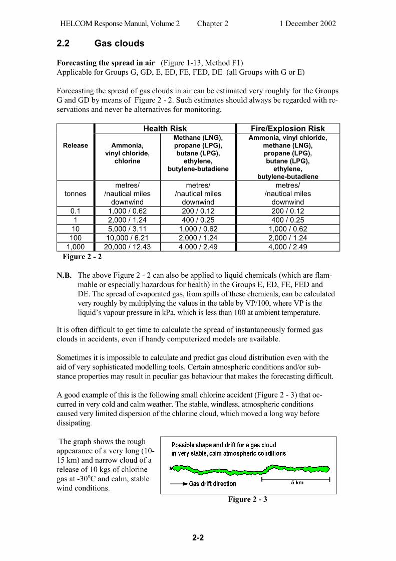
2.2 Gas clouds Forecasting the spread in air (Figure 1-13, Method F1) Applicable for Groups G, GD, E, ED, FE, FED, DE (all Groups with G or E) Forecasting the spread of gas clouds in air can be estimated very roughly for the Groups G and GD by means of Figure 2 - 2. Such estimates should always be regarded with re-servations and never be alternatives for monitoring.
Health Risk Fire/Explosion Risk
Release
Ammonia, vinyl chloride,
chlorine
Methane (LNG), propane (LPG), butane (LPG),
ethylene, butylene-butadiene
Ammonia, vinyl chloride, methane (LNG), propane (LPG), butane (LPG),
ethylene, butylene-butadiene
tonnes
metres/ /nautical miles
downwind
metres/ /nautical miles
downwind
metres/ /nautical miles
downwind 0.1 1,000 / 0.62 200 / 0.12 200 / 0.12 1 2,000 / 1.24 400 / 0.25 400 / 0.25
10 5,000 / 3.11 1,000 / 0.62 1,000 / 0.62 100 10,000 / 6.21 2,000 / 1.24 2,000 / 1.24
1,000 20,000 / 12.43 4,000 / 2.49 4,000 / 2.49 Figure 2 - 2
N.B. The above Figure 2 - 2 can also be applied to liquid chemicals (which are flam-
mable or especially hazardous for health) in the Groups E, ED, FE, FED and DE. The spread of evaporated gas, from spills of these chemicals, can be calculated very roughly by multiplying the values in the table by VP/100, where VP is the liquid’s vapour pressure in kPa, which is less than 100 at ambient temperature.
It is often difficult to get time to calculate the spread of instantaneously formed gas clouds in accidents, even if handy computerized models are available. Sometimes it is impossible to calculate and predict gas cloud distribution even with the aid of very sophisticated modelling tools. Certain atmospheric conditions and/or sub-stance properties may result in peculiar gas behaviour that makes the forecasting difficult. A good example of this is the following small chlorine accident (Figure 2 - 3) that oc-curred in very cold and calm weather. The stable, windless, atmospheric conditions caused very limited dispersion of the chlorine cloud, which moved a long way before dissipating. The graph shows the rough appearance of a very long (10-15 km) and narrow cloud of a release of 10 kgs of chlorine gas at -30oC and calm, stable wind conditions.
Figure 2 - 3
HELCOM Response Manual, Volume 2 Chapter 2 1 December 2002
2-3
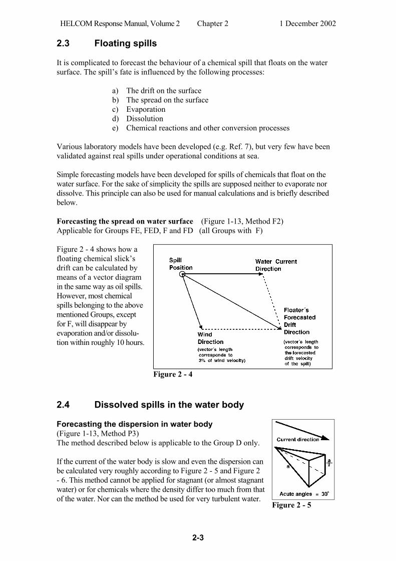
2.3 Floating spills It is complicated to forecast the behaviour of a chemical spill that floats on the water surface. The spill’s fate is influenced by the following processes: a) The drift on the surface b) The spread on the surface c) Evaporation d) Dissolution e) Chemical reactions and other conversion processes Various laboratory models have been developed (e.g. Ref. 7), but very few have been validated against real spills under operational conditions at sea. Simple forecasting models have been developed for spills of chemicals that float on the water surface. For the sake of simplicity the spills are supposed neither to evaporate nor dissolve. This principle can also be used for manual calculations and is briefly described below. Forecasting the spread on water surface (Figure 1-13, Method F2) Applicable for Groups FE, FED, F and FD (all Groups with F) Figure 2 - 4 shows how a floating chemical slick’s drift can be calculated by means of a vector diagram in the same way as oil spills. However, most chemical spills belonging to the above mentioned Groups, except for F, will disappear by evaporation and/or dissolu-tion within roughly 10 hours.
Figure 2 - 4
2.4 Dissolved spills in the water body Forecasting the dispersion in water body (Figure 1-13, Method P3) The method described below is applicable to the Group D only. If the current of the water body is slow and even the dispersion can be calculated very roughly according to Figure 2 - 5 and Figure 2 - 6. This method cannot be applied for stagnant (or almost stagnant water) or for chemicals where the density differ too much from that of the water. Nor can the method be used for very turbulent water.
Figure 2 - 5
HELCOM Response Manual, Volume 2 Chapter 2 1 December 2002
2-4
Concentration 1 g/m3 Concentration 1 mg/m3 Release tonnes a metres nautical miles a metres nautical miles
1 500 0.3 5,000 3 10 1,000 0.5 10,000 5 100 2,000 1 20,000 11
1,000 4,000 2 40,000 22 Figure 2 - 6
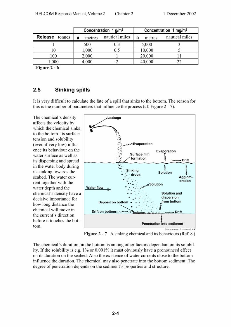
2.5 Sinking spills It is very difficult to calculate the fate of a spill that sinks to the bottom. The reason for this is the number of parameters that influence the process (cf. Figure 2 - 7).
Picture source: P. Ashworth, UK
The chemical’s density affects the velocity by which the chemical sinks to the bottom. Its surface tension and solubility (even if very low) influ-ence its behaviour on the water surface as well as its dispersing and spread in the water body during its sinking towards the seabed. The water cur-rent together with the water depth and the chemical’s density have a decisive importance for how long distance the chemical will move in the current’s direction before it touches the bot-tom.
Figure 2 - 7 A sinking chemical and its behaviours (Ref. 8.) The chemical’s duration on the bottom is among other factors dependant on its solubil-ity. If the solubility is e.g. 1% or 0.001% it must obviously have a pronounced effect on its duration on the seabed. Also the existence of water currents close to the bottom influence the duration. The chemical may also penetrate into the bottom sediment. The degree of penetration depends on the sediment’s properties and structure.

HELCOM Response Manual, Volume 2 Chapter 2 1 December 2002
2-5
2.6 Forecasting modelling systems 2.6.1 Introduction There exist hundreds of highly sophisticated forecasting modelling systems for predic-tion of the drift and spread of chemical spills. Many of them are highly theoretical and not so easy to use. It is a difficult task to find models that might be usable in an opera-tional organisation. A few known systems have been selected as examples below in Section 2.6.2. 2.6.2 Examples of computerized modelling systems Forecasting computer model Name ALOHA (Areal Locations of Hazardous Atmospheres)
Application Gases
Information Emergency responders can use ALOHA to predict the behaviour of a chemical gas in the event of an accidental release. ALOHA is a part of the decision support system CAMEO (Computer Aided Management of Emergency Operations) developed by US Na-tional Oceanic and Atmospheric Administration (NOAA) in coop-eration with US Environmental Protection Agency (EPA). (Ref. 6) http://response.restoration.noaa.gov/ cameo/aloha.html
Figure 2 - 8 Graphical ALOHA description of a gas cloud dispersion in air.
Properties
Can predict rates of chemical release from broken gas pipes, leaking tanks, and evaporating puddles, and can model the dispersion of both neutrally-buoyant and heavier-than-air gases.
Advantages Free of charge. Technical assistance is available.
Limitations
Mainly aimed for gas releases over land under conditions where the wind speed is neither too low nor too high. Does not account for topographic effects. The earth is assumed to be flat and the mean wind speed and direction are assumed to be uniform at any given reference height.
HELCOM Response Manual, Volume 2 Chapter 2 1 December 2002
2-6
Forecasting computer model Name MET (Modells für Effekte mit Toxischen Gasen)
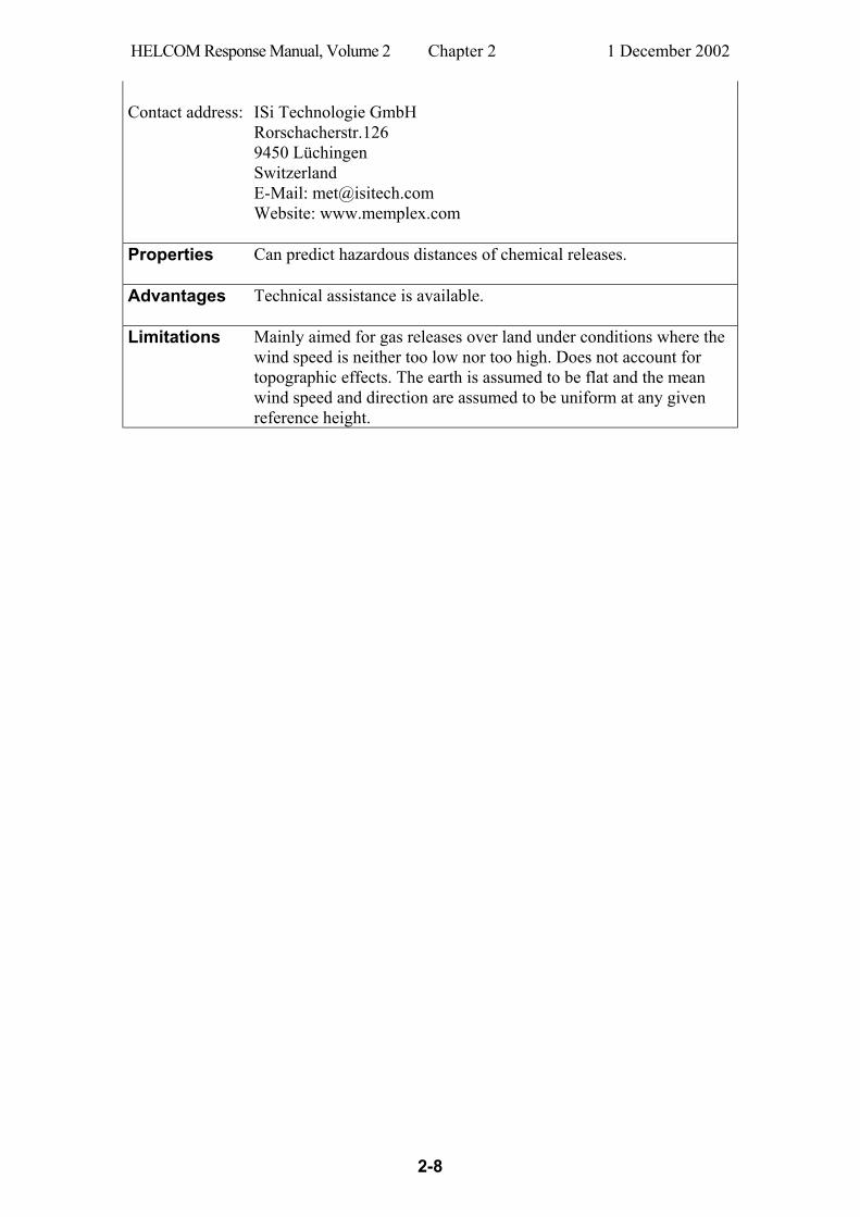
Application Gases
Information In accidents when hazardous gases are released into the air it is not satisfactory just to calculate gas concentrations in order to make rapid assessment of health risks and safety distances. The reason is that inhalation of high concentrations during short time will give the same dose as lower concentrations inhaled over a longer period. Calcula-tion of safety distances should therefore be based on both concentrations and emission or spill rates. MET makes a dose-effect-coupling for effects of toxic gases and estimates risks of human injuries in the area in the wind direction of the accidental release. The dose as integral of concentration versus time is a good criterion in a model, since it diminishes one important but uncertain source term, the emission time. But doses also are not significant enough, since there is a further toxicological step to the main aim, to estimate the effect of toxic substances on the people in the surrounding area. MET consists of the following four main modules:
1. The instantaneous release of toxic substances as a puff and the formation of a gas/air cloud mixture.
2. The dispersion of the toxic gases and calculation of the concentrations as a func-tion of the distance (half sphere box model).
3. The transformation into doses.
4. The dose/effect-coupling based on a modified pharmacological receptor theory to evaluate the health impact.
The input values that MET needs are: 1) escaped substance weight, 2) wind speed and 3) a threshold value for the substance. Other parameters are automatically provided by the system in order to calculate hazardous distances. MET has modules for simulations of 1) the washout effect of the cloud by rain, 2) the influence of a simultaneous fire and 3) the dispersion characteristics of heavy gases. The model is stable to the large variations of the toxic values, since it can integrate several different values. In addition the lower explosion limit is used to calculate the size of an explosive mixture of a substance and air. The effects on mixtures of sub-stances e.g. from fires can also be calculated.
HELCOM Response Manual, Volume 2 Chapter 2 1 December 2002
2-7
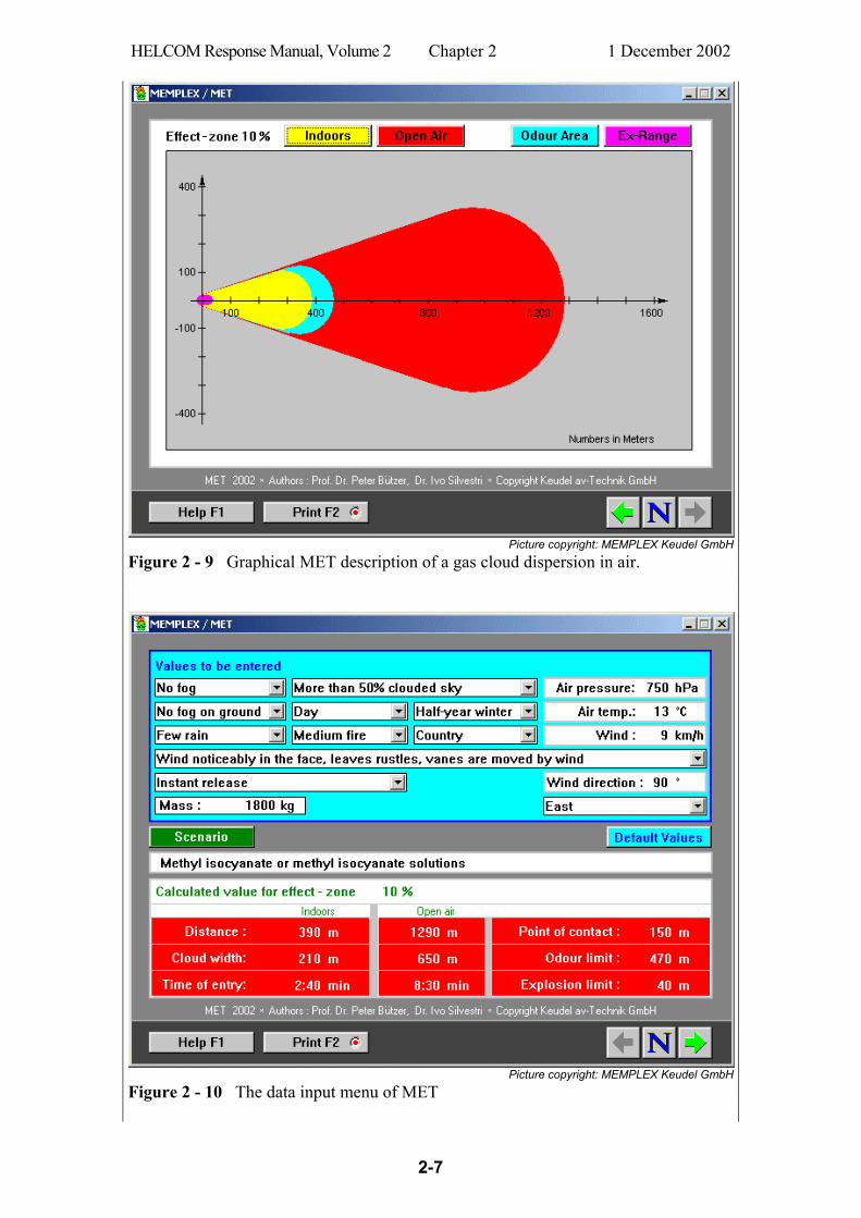
Picture copyright: MEMPLEX Keudel GmbH
Figure 2 - 9 Graphical MET description of a gas cloud dispersion in air.
Picture copyright: MEMPLEX Keudel GmbH
Figure 2 - 10 The data input menu of MET
HELCOM Response Manual, Volume 2 Chapter 2 1 December 2002
2-8
Contact address: ISi Technologie GmbH
Rorschacherstr.126 9450 Lüchingen Switzerland E-Mail: [email protected] Website: www.memplex.com
Properties
Can predict hazardous distances of chemical releases.
Advantages Technical assistance is available.
Limitations
Mainly aimed for gas releases over land under conditions where the wind speed is neither too low nor too high. Does not account for topographic effects. The earth is assumed to be flat and the mean wind speed and direction are assumed to be uniform at any given reference height.
HELCOM Response Manual, Volume 2 Chapter 2 1 December 2002
2-9
Forecasting computer model Name CHEMMAP
Application Floaters, dissolvers, and sinkers
Properties
Predicts the dispersion and fate of marine chemical spills.
Information CHEMMAP is developed by Applied Science Associates, Inc. (ASA), Rhode Island, USA. CHEMMAP predicts the likely trajectory and fate chemical spills in the marine envi-ronment. The system is particularly suited to contingency planning and emergency response for spills of chemical cargoes from ships but may be applied to any chemical discharge. The system contains GIS and a 3D spill model that predicts the movement of chemicals in the water. The model relies on environmental data such as wind and currents, physical data such as the proximity of shorelines, and chemical data that de-fine the chemical's properties. CHEMMAP includes a biological effects model which evaluates the effects of chemical spills on fish, shellfish and wildlife. CHEMMAP incorporates a number of model components including: - simulation of the initial release and plume dynamics of a product lighter or denser than water - slick spreading and transport of floating materials - transport of dissolved and particulate materials in three dimensions - evaporation and volatilization - dissolution and adsorption - sedimentation, resuspension and degradation The model uses physical-chemical properties to predict the fate of a chemical spill. These include density, vapour pressure, water solubility, environmental degradation rates, adsorbed/dissolved partitioning coefficient (KOC), viscosity, and surface tension. CHEMMAP has its own database of 900 chemicals with physical and chemical data properties. A software link is optionally available to a database of more than 40,000 pure substances and 75,000 common mixtures. The latter database also provide guidelines for how to determine the severity of the risk to health, how to handle a spill, how to store and transport chemicals, how to dispose of chemicals, what to do if a chemical catches fire and how to plan for an emergency response. Figure 2 - 11 shows the modelling of an instantaneous release of benzene (10,000 met-ric tons) at the water surface. The plume display is the Vertical Maximum Dissolved Concentration of Benzene in the water column (mg/m3) 40 hrs after the initial release. The colour-coded legend is located to the right of the plume with a cross section show-ing the plume in 3-dimensions below the legend. Above the plume is a graph of the mass balance that displays the percent of chemical that has surfaced, evaporated, in the water column, in or on the sediment and what has gone ashore over time.
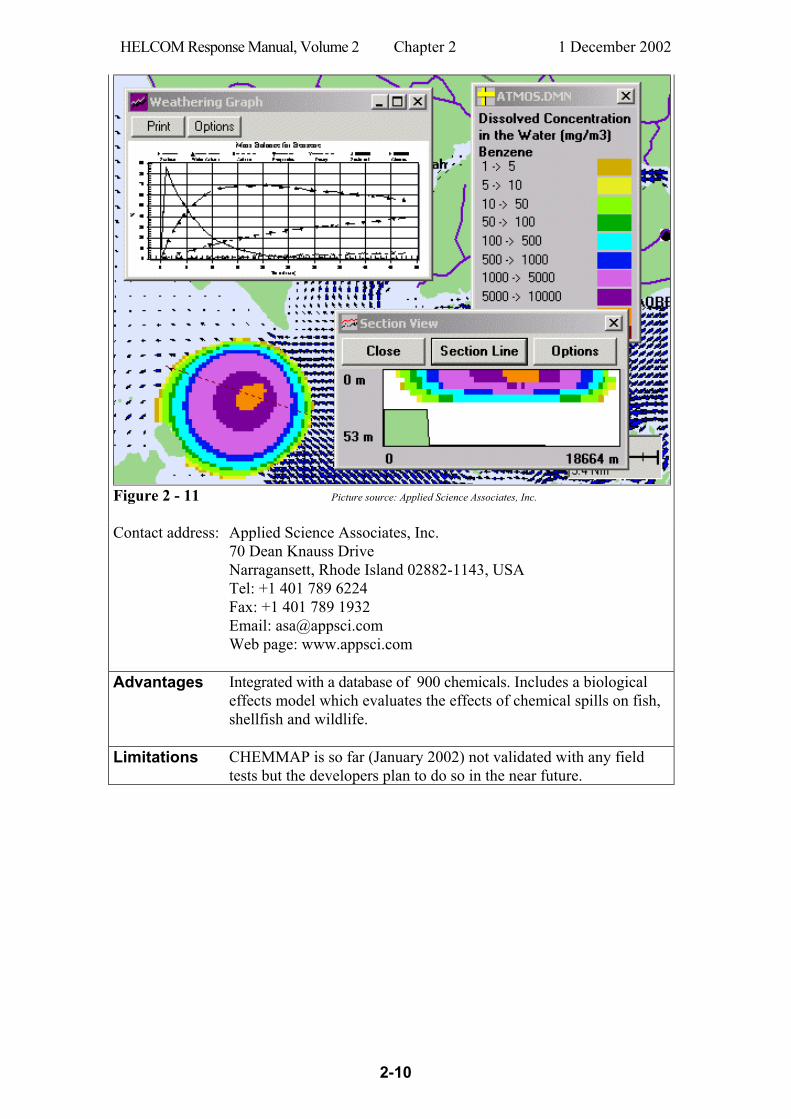
HELCOM Response Manual, Volume 2 Chapter 2 1 December 2002
2-10
Figure 2 - 11 Picture source: Applied Science Associates, Inc. Contact address: Applied Science Associates, Inc.
70 Dean Knauss Drive Narragansett, Rhode Island 02882-1143, USA Tel: +1 401 789 6224 Fax: +1 401 789 1932 Email: [email protected] Web page: www.appsci.com
Advantages Integrated with a database of 900 chemicals. Includes a biological effects model which evaluates the effects of chemical spills on fish, shellfish and wildlife.
Limitations
CHEMMAP is so far (January 2002) not validated with any field tests but the developers plan to do so in the near future.
HELCOM Response Manual, Volume 2 Chapter 2 1 December 2002
2-11
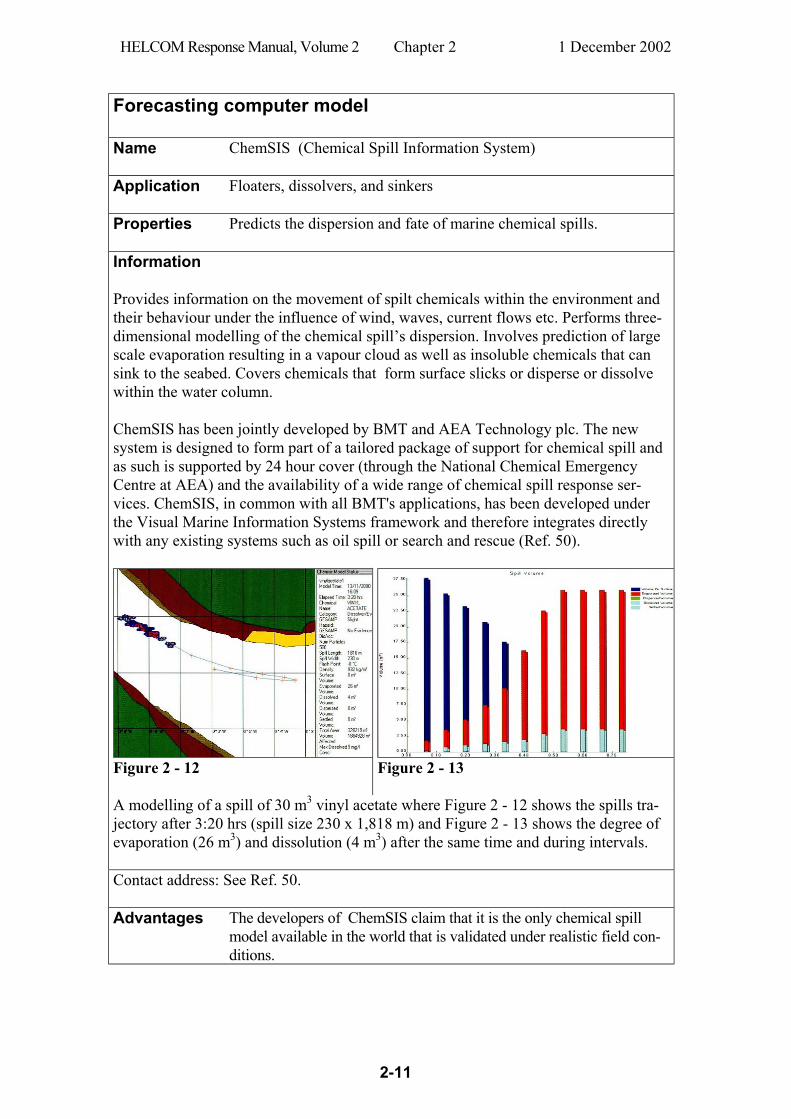
Forecasting computer model Name ChemSIS (Chemical Spill Information System)
Application Floaters, dissolvers, and sinkers
Properties
Predicts the dispersion and fate of marine chemical spills.
Information
Provides information on the movement of spilt chemicals within the environment and their behaviour under the influence of wind, waves, current flows etc. Performs three-dimensional modelling of the chemical spill’s dispersion. Involves prediction of large scale evaporation resulting in a vapour cloud as well as insoluble chemicals that can sink to the seabed. Covers chemicals that form surface slicks or disperse or dissolve within the water column. ChemSIS has been jointly developed by BMT and AEA Technology plc. The new system is designed to form part of a tailored package of support for chemical spill and as such is supported by 24 hour cover (through the National Chemical Emergency Centre at AEA) and the availability of a wide range of chemical spill response ser-vices. ChemSIS, in common with all BMT's applications, has been developed under the Visual Marine Information Systems framework and therefore integrates directly with any existing systems such as oil spill or search and rescue (Ref. 50).
Figure 2 - 12
Figure 2 - 13
A modelling of a spill of 30 m3 vinyl acetate where Figure 2 - 12 shows the spills tra-jectory after 3:20 hrs (spill size 230 x 1,818 m) and Figure 2 - 13 shows the degree of evaporation (26 m3) and dissolution (4 m3) after the same time and during intervals. Contact address: See Ref. 50. Advantages The developers of ChemSIS claim that it is the only chemical spill
model available in the world that is validated under realistic field con-ditions.
HELCOM Response Manual, Volume 2 Chapter 2 1 December 2002
2-12
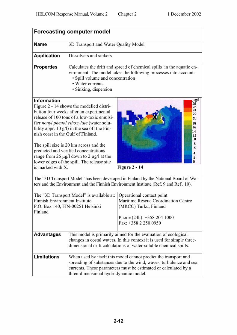
Forecasting computer model Name 3D Transport and Water Quality Model
Application Dissolvers and sinkers
Properties
Calculates the drift and spread of chemical spills in the aquatic en-vironment. The model takes the following processes into account: • Spill volume and concentration • Water currents • Sinking, dispersion
Information Figure 2 - 14 shows the modelled distri-bution four weeks after an experimental release of 100 tons of a low-toxic emulsi-fier nonyl phenol ethoxylate (water solu-bility appr. 10 g/l) in the sea off the Fin-nish coast in the Gulf of Finland. The spill size is 20 km across and the predicted and verified concentrations range from 26 µg/l down to 2 µg/l at the lower edges of the spill. The release site is marked with X.
Figure 2 - 14
The ”3D Transport Model” has been developed in Finland by the National Board of Wa-ters and the Environment and the Finnish Environment Institute (Ref. 9 and Ref . 10). The ”3D Transport Model” is available at: Finnish Environment Institute P.O. Box 140, FIN-00251 Helsinki Finland
Operational contact point Maritime Rescue Coordination Centre (MRCC) Turku, Finland Phone (24h): +358 204 1000 Fax: +358 2 250 0950
Advantages This model is primarily aimed for the evaluation of ecological changes in costal waters. In this context it is used for simple three-dimensional drift calculations of water-soluble chemical spills.
Limitations
When used by itself this model cannot predict the transport and spreading of substances due to the wind, waves, turbulence and sea currents. These parameters must be estimated or calculated by a three-dimensional hydrodynamic model.
HELCOM Response Manual, Volume 2 Chapter 3 1 December 2002
3-1
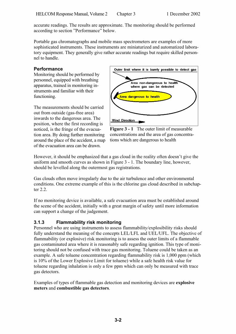
3 Monitoring and body protection 3.1 Gas monitoring by portable instruments 3.1.1 Introduction Purpose of monitoring In chemical accidents it is crucial to monitor the air for concentrations of hazardous substances. The aim of gas monitoring is to assess both toxic and fire/explosion hazards as well as map the area where unprotected personnel should be evacuated and judge the appropriate level of body protection for response personnel. On some occasions the read-out values can be used directly for designing risk areas (cf. Figure 3 - 1). In other circumstances the instruments can be used to check risk areas that are already assessed or defined according to some calculation method or forecasting model. The most difficult measuring task on a site of a chemical accident is to make rapid identification of unknown airborne substances by means of portable instruments. Such work requires sophisticated instruments and trained expertise often not available when the first risk assessment is going to be made. Proper use of portable gas monitoring instruments generally require exact knowledge of the gas identity. Luckily this is often the case. Especially when a single chemical substance is involved, its identity is often known to the responders. Monitoring instruments In the world market there are hundreds of manufacturers offering thousands of different models of hand-held, portable, transportable or mobile gas detection and monitoring instruments that can be used during chemical accidents for risk assessment and evalua-tion. It is a rapidly developing market and it is difficult to give good advice on particular brands and models of instruments. Therefore this Chapter is limited to rather brief dis-cussions on essentials in this field. Ref. 51 is an example of a broad overview of princi-ples of hazardous gas monitors and serves as a guide to the selection of types of instru-ments. Calibration Many instruments require calibration before use! It is therefore crucial to follow the instructions carefully in this respect. 3.1.2 Trace gas monitoring The main objectives of trace gas monitoring in case of a chemical accident are to find dangerous locations of a toxic gas contaminated area and assess the outer limits where it is reasonably safe for unprotected personnel. This type of instruments must be able to detect very low concentrations of hazardous gases (ppm-levels). Examples of types of hand-held or mobile trace gas detection and monitoring devices: Gas detection tubes IR trace gas detectors Semiconductor instruments Portable gas chromatographs Photoionization instruments Mobile mass spectrometers Gas detector tubes, semiconductor instruments and some photoionization instruments are relatively simple hand-held devices. Note that these instrument cannot be used for
HELCOM Response Manual, Volume 2 Chapter 3 1 December 2002
3-2
accurate readings. The results are approximate. The monitoring should be performed according to section ”Performance” below. Portable gas chromatographs and mobile mass spectrometers are examples of more sophisticated instruments. These instruments are miniaturized and automatized labora-tory equipment. They generally give rather accurate readings but require skilled person-nel to handle. Performance Monitoring should be performed by personnel, equipped with breathing apparatus, trained in monitoring in-struments and familiar with their functioning. The measurements should be carried out from outside (gas-free area) inwards to the dangerous area. The position, where the first recording is noticed, is the fringe of the evacua-tion area. By doing further monitoring around the place of the accident, a map of the evacuation area can be drawn.
Figure 3 - 1 The outer limit of measurable concentrations and the area of gas concentra-tions which are dangerous to health
However, it should be emphasized that a gas cloud in the reality often doesn’t give the uniform and smooth curves as shown in Figure 3 - 1. The boundary line, however, should be levelled along the outermost gas registrations. Gas clouds often move irregularly due to the air turbulence and other environmental conditions. One extreme example of this is the chlorine gas cloud described in subchap-ter 2.2. If no monitoring device is available, a safe evacuation area must be established around the scene of the accident, initially with a great margin of safety until more information can support a change of the judgement. 3.1.3 Flammability risk monitoring Personnel who are using instruments to assess flammability/explosibility risks should fully understand the meaning of the concepts LEL/LFL and UEL/UFL. The objective of flammability (or explosive) risk monitoring is to assess the outer limits of a flammable gas contaminated area where it is reasonably safe regarding ignition. This type of moni-toring should not be confused with trace gas monitoring. Toluene could be taken as an example. A safe toluene concentration regarding flammability risk is 1,000 ppm (which is 10% of the Lower Explosive Limit for toluene) while a safe health risk value for toluene regarding inhalation is only a few ppm which can only be measured with trace gas detectors. Examples of types of flammable gas detection and monitoring devices are explosive meters and combustible gas detectors.

HELCOM Response Manual, Volume 2 Chapter 3 1 December 2002
3-3
3.1.4 Oxygen-Deficient Air Monitoring The oxygen level in confined spaces, such as cargo holds or tanks, can decrease because of work being done, such as welding, cutting, or brazing. It can also be decreased by oxygen-consuming reactions (metal rusting or cargo oxidation) or through microbial action (fermentation). The oxygen concentration is also decreased if air is displaced by another gas, such as inert gas, carbon dioxide, nitrogen or hydrocarbons. If such a gas causes total displace-ment of oxygen, an unprotected person will rapidly become unconscious and die. Oxygen-deficient means that there is not enough oxygen in the space to safety breathe. Normal fresh air contains 20.8 percent oxygen compared to less than 19.5 percent in an oxygen-deficient atmosphere. Air that has less than 10 percent oxygen can rapidly cause unconsciousness and levels below 8 percent can quickly cause death. The objective of oxygen-deficient air monitoring instruments is to assess the outer limits of an oxygen deficient area where it is reasonably safe for unprotected personnel (Oxygen concentration above 19.5%). Any atmosphere with less than 19.5% oxygen should not be entered without an approved self-contained breathing apparatus (SCBA). Examples of monitoring devices are chemical celloxygen meters. 3.2 Monitoring the water column Monitoring the dispersion of chemical spills in the water body is often performed by taking water samples with hand-held devices at various positions and analyzing the samples for the actual chemical. Sometimes the analyses can be made by portable equipment, but on many occasions the samples must be carried to stationary laboratories. Well-equipped portable laboratories exist which can be placed close to the site of the accident (cf. Ref. 52 and 53). Monitoring can be achieved in some systems by probes containing parts of the analytical equipment that can perform the analyses more or less automatically. The probe is manually submerged or is towed (cf. Figure 3 - 2). Selection of measurement princi-ple and monitoring equipment is based on the type of spilled chemical.
Figure 3 - 2 Monitoring the water body by a towed probe.
The physical principle of measurement may be for instance pH, light absorption, electrical conductivity or turbidity. Low concentrations of many organic substances (e.g. hydrocarbons or halogenated hydrocarbons) may be very difficult to measure with portable equipment. However, in recent years different types of sophisticated active-service equipment have been devel-oped capable of monitoring such substances in low concentrations. One example of equipment is based on enzymatic techniques (Ref. 54). Such monitoring must often be carried out by specially experienced personnel.
HELCOM Response Manual, Volume 2 Chapter 3 1 December 2002
3-4
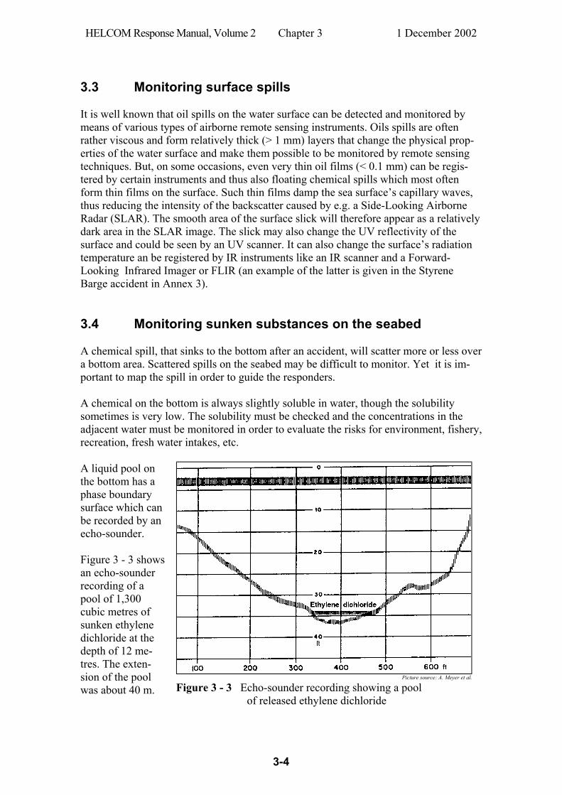
3.3 Monitoring surface spills It is well known that oil spills on the water surface can be detected and monitored by means of various types of airborne remote sensing instruments. Oils spills are often rather viscous and form relatively thick (> 1 mm) layers that change the physical prop-erties of the water surface and make them possible to be monitored by remote sensing techniques. But, on some occasions, even very thin oil films (< 0.1 mm) can be regis-tered by certain instruments and thus also floating chemical spills which most often form thin films on the surface. Such thin films damp the sea surface’s capillary waves, thus reducing the intensity of the backscatter caused by e.g. a Side-Looking Airborne Radar (SLAR). The smooth area of the surface slick will therefore appear as a relatively dark area in the SLAR image. The slick may also change the UV reflectivity of the surface and could be seen by an UV scanner. It can also change the surface’s radiation temperature an be registered by IR instruments like an IR scanner and a Forward-Looking Infrared Imager or FLIR (an example of the latter is given in the Styrene Barge accident in Annex 3). 3.4 Monitoring sunken substances on the seabed A chemical spill, that sinks to the bottom after an accident, will scatter more or less over a bottom area. Scattered spills on the seabed may be difficult to monitor. Yet it is im-portant to map the spill in order to guide the responders. A chemical on the bottom is always slightly soluble in water, though the solubility sometimes is very low. The solubility must be checked and the concentrations in the adjacent water must be monitored in order to evaluate the risks for environment, fishery, recreation, fresh water intakes, etc.
Picture source: A. Meyer et al.
A liquid pool on the bottom has a phase boundary surface which can be recorded by an echo-sounder. Figure 3 - 3 shows an echo-sounder recording of a pool of 1,300 cubic metres of sunken ethylene dichloride at the depth of 12 me-tres. The exten-sion of the pool was about 40 m.
Figure 3 - 3 Echo-sounder recording showing a pool of released ethylene dichloride
HELCOM Response Manual, Volume 2 Chapter 3 1 December 2002
3-5
Other types of recordings and more detailed mapping can be done by using divers and/or submersibles (cf. subchapter 6.7). 3.5 Miscellaneous monitoring methods Needs may arise on certain occasions to co-operate with special expertise to carry out various kinds of sampling and monitoring to assess the degree of harmful environ-mental interference or impact by a chemical pollutant. Examples are monitoring con-centrations of chemicals in marine organisms and bottom sediments. On rare occasions very unusual substances may have to be monitored, e.g. radioactive or infectious substances, chemical or biological warfare agents, etc. Highly specialized personnel must be engaged for such work. Extensive trials have been made utilizing dogs to trace various chemicals (Ref. 55, 56 and 57). That this principle, "canine olfaction", is regarded as serious is shown by the fact that US Environmental Protection Agency has completed a research project in this field (Ref. 56). This project showed that dog’s ability to detect airborne traces of chemi-cals was better than the trace gas monitoring instruments used for comparison. 3.6 Levels of body protection during chemical accidents When response activities are conducted where atmospheric contamination is known or suspected to exist, personal protective equipment must be worn. Personal protective equipment is designed to prevent/reduce skin and eye contact as well as inhalation or ingestion of the chemical substance. Protective equipment to protect the body against contact with known or anticipated chemical hazards are divided into four categories Level A – D. These levels are briefly indicated in Figure 3 - 4 below and are specified in some detail in Annex 5. Level
Remark
A Highest level of respiratory, skin, and eye protection
B Highest level of respiratory, skin, and eye protection; The breathing apparatus is worn outside the suit
C The types of airborne substance is known and the criteria for using air purifying respirators are met
D A work uniform affording minimal protection, used for irritating contamination only
Figure 3 - 4 Level A protection should always be used if the airborne substances are unidentified. The type of environment and the overall level of protection should be revaluated peri-odically during the operation when more information is gained about the hazards.
HELCOM Response Manual, Volume 2 Chapter 4 1 December 2002
4-1
4 Sampling 4.1 General 4.1.1 Purposes of sampling General Sampling and subsequent analysis shall answer questions regarding spills’ origin as well as their properties and effects. To accomplish this, samples should be taken for several different purposes, which are dealt with in this Chapter. Some spills may involve contacts and co-ordination with other countries regarding sampling and analysis. Occasionally, foreign agencies should be contacted to exchange samples, analysis results, examination reports, etc. The following list describes eight purposes of sampling after incidents or accidents involving hazardous substances or packaged dangerous goods. Most often only a few of them are appropriate in a specific case. 1. Occupational safety
When necessary, the spill should be examined (analysed) to establish whether there are any health risks for the response personnel. The substance may be flam-mable and cause fire and/or explosion, or may be toxic and cause danger to health if inhaled or exposed to skin.
2. Penal liability The responsible polluter should, if possible, be identified and be charged for the spill. This can be done by comparing chemical analyses of samples from the spill with samples from suspected sources. If identity is established be-tween the spill and a suspected source, this can help to identify the polluter.
3. Polluter’s economical liability The results of sampling have often been used as a basis for compensation claims against the polluter. These claims may concern costs associated with response and cleanup measures, or damage to property, fishery, recreational areas, etc. Above all, it is important to tie the suspected polluter to the damage in order to confirm the claims.
4. Spill response planning On some occasions, special analyses can give important information that can support planning of response and cleanup work. It is important to study chemical and physical property data of the substance when selecting equip-ment and methods as well as safety routines for the response operation.
5. Short term environmental protection
The substance’s acute deleterious effects on the environment can vary consid-erably depending on its properties. Many chemicals show acute toxic effects to the marine life and some substances have a tendency to smear beaches, plants and animals. Besides identifying the substance it may be necessary to sample and analyse the water column, sediment, organisms, etc.
HELCOM Response Manual, Volume 2 Chapter 4 1 December 2002
4-2
6. Long term environmental protection
Certain substances may cause long term deleterious effects on the environment, and some species may be knocked out, or the environment be polluted for a long time. Assessment should be made to judge how the environment can be restored. It may be necessary to sample and analyse the substance itself, as well as water, sediment, organisms, etc.
7. Information service Many and sometimes tricky questions are asked about the substance’s proper-ties and effects, especially when facing a large or hazardous spillage. In such cases it is important to give rapid and correct information in order to reduce anxiousness and circulating of rumours. Sampling and analysis can thereby provide the basis for information to be given and for the choice of informa-tion channels. When informing the public, and those who are directly affected by the spill, it is important to account for certain data, for example: the spill’s origin and extension the substance’s properties and spread in the environment effects on human and environment consequences for various parties and bodies ongoing work regarding response, cleanup and disposal
8. Disposal The selection of techniques for the subsequent disposal is based on the type of substance and its properties, and the spill’s volume. Many disposal plants are specialized for certain hazardous materials and cannot process other types.
4.1.2. Responsibilities during sampling Spills occur every day in the marine as well as inland aquatic environment. Although most of the spills are very small, they still often require sampling to get a chance of linking them to the responsible polluters and assess the damage to environment. It is therefore important to trace all conceivable polluters as soon as possible. There is a great need for co-ordination as the sampling activities for spills and suspected sources may go on simultaneously at different places. This work may very well be performed by a permanent Sampling Co-ordinator within the environmental response organisation. This Co-ordinator should be subordinated to the District Chief of the Environmental Response Organisation. During the Organisation’s everyday work the Sampling Co-ordinator keeps record of spill samples from various sites and initiates sampling on board suspected sources when overlooked by the field officers. The sampling activities may increase considerably during more significant accidents involving spills of hazardous materials. Many different samples may be taken for sev-eral different purposes. Many authorities and institutions may be involved in the sam-pling activities and a confusing situation may arise where different bodies work, per-haps without being aware of each other. On such occasions, it is crucial to co-ordinate the activities to avoid duplication of work, as well as to avoid missing chances of impor-tant sampling. Such co-ordination could also promote prevention of anxiousness and circulating of rumours which often happen during major and hazardous spill accidents. In this situation, the Environmental Response Commander should appoint an ad hoc Sampling Co-ordinator to be responsible for the overall co-ordination of all sampling work during the run of the response operation.
HELCOM Response Manual, Volume 2 Chapter 4 1 December 2002
4-3
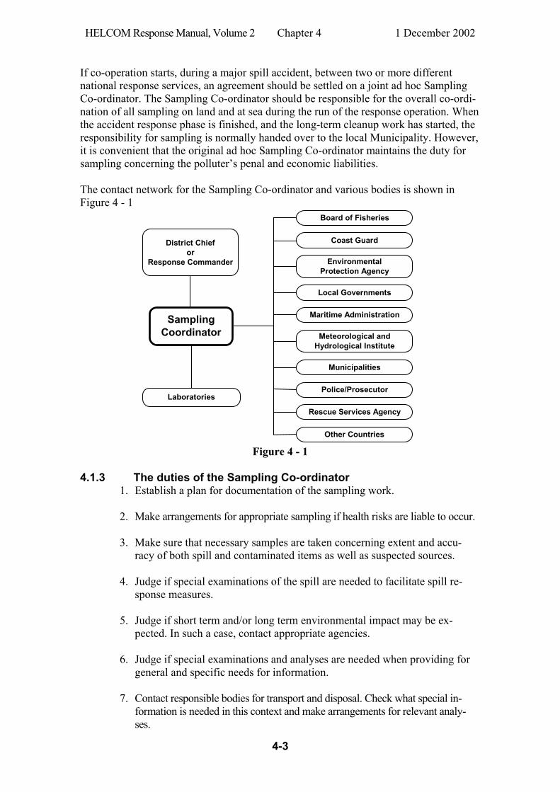
If co-operation starts, during a major spill accident, between two or more different national response services, an agreement should be settled on a joint ad hoc Sampling Co-ordinator. The Sampling Co-ordinator should be responsible for the overall co-ordi-nation of all sampling on land and at sea during the run of the response operation. When the accident response phase is finished, and the long-term cleanup work has started, the responsibility for sampling is normally handed over to the local Municipality. However, it is convenient that the original ad hoc Sampling Co-ordinator maintains the duty for sampling concerning the polluter’s penal and economic liabilities. The contact network for the Sampling Co-ordinator and various bodies is shown in Figure 4 - 1
SamplingCoordinator
District Chiefor
Response Commander
Board of Fisheries
Coast Guard
EnvironmentalProtection Agency
Local Governments
Maritime Administration
Meteorological andHydrological Institute
Municipalities
Police/Prosecutor
Rescue Services Agency
Other Countries
Laboratories
Figure 4 - 1
4.1.3 The duties of the Sampling Co-ordinator 1. Establish a plan for documentation of the sampling work.
2. Make arrangements for appropriate sampling if health risks are liable to occur.
3. Make sure that necessary samples are taken concerning extent and accu-
racy of both spill and contaminated items as well as suspected sources.
4. Judge if special examinations of the spill are needed to facilitate spill re-sponse measures.
5. Judge if short term and/or long term environmental impact may be ex-pected. In such a case, contact appropriate agencies.
6. Judge if special examinations and analyses are needed when providing for general and specific needs for information.
7. Contact responsible bodies for transport and disposal. Check what special in-formation is needed in this context and make arrangements for relevant analy-ses.
HELCOM Response Manual, Volume 2 Chapter 4 1 December 2002
4-4
4.1.4 General checklist for sampling
1. Sampling actions on unknown materials should be taken on a “worst possi-ble case basis”, i.e. if nothing is known whatsoever about the substance it should be considered as extremely hazardous and due safety precautions should be taken.
2. All spills encountered and all potential sources of spills should be sampled. It is important to take samples from both spill and source even on such occasions where it seems quite clear from where the spill originates. Use at first hand the type of sampling equipment and routines described in this Chapter.
3. Sampling procedures, which are connected to liability investigations, must be performed with great care and accuracy concerning spills as well as suspected sources. Every action should be taken to prevent a decrease in the samples’ value as evidence.
4. If a spill has scattered on the water surface and only thin sheens remain, yet every possible effort should be made to take at least a small sample. No sample volume is too small to be shipped to the laboratory. The laboratory can often analyse very small samples, for example water samples that seem-ingly consist of pure water or sample pads that do not show any trace of substance.
5. Assistance should be received from appropriate expertise on occasions of hesitation. All sampling of chemicals on board vessels or in other sources should, if possible, be left to the crew or staff, or should be carried out in close co-operation with the crew/staff. Special safety precautions must be taken during sampling activities in atmospheres that might be explosive.
6. Samples and sampling equipment should be handled and stored so that the samples cannot be manipulated, mixed up, or else be contaminated by strange substances. Samples should be handled as legal evidence and should be kept in a “chain of custody” until identification and possible legal proce-dure has been completed. Therefore, always use a type of sealable and indi-vidually numbered safety bags described later in this Chapter.
7. A bottle containing a sample should not be placed in the sampling kit to-
gether with the clean equipment. Reusable sampling equipment should always be very carefully cleaned, and put into clean plastic bags, before restoring in the sampling kit case. Used sample bottles must not be used again - not even after careful washing.
8. Make notes of all relevant information about samples and sample sites. Use a miniature camera or a video camera to record observations which are considered important for the investigation.
9. The samples should be immediately sent to the Sample Co-ordinator. Quick handling of samples is important. If the transmittal is delayed the samples should be kept under a temperature of less than +4°C
HELCOM Response Manual, Volume 2 Chapter 4 1 December 2002
4-5
10. Consumed equipment should be replaced as soon as possible so that the
sampling kit case always is fit for use and so that new samples can always be quickly taken, packed and sent away.
4.1.5 Handling of spill information A whole chain of activities leads to the information to be presented about the spill. This chain consists of: Sampling Sample keeping and transmittal Identification, labelling, documentation Chemical, physical and biological analyses Judgement of the analysis results Presentation of the analysis results Each step must be taken with care and accuracy. This is a prerequisite for a compilation of an information report which is as capable as the circumstances allow. Points to be observed during sampling and subsequent handling of samples, are for example: Several samples must be taken from spills covering large areas or divided in
several locations.
Sampling in a suspected source must be performed in such a careful way that the suspected polluter with certainty can be tied to, or cleared of, the spill.
All samples must be labelled so that they can be unmistakably referred to the sampling points.
Sample containers must be labelled, closed and kept in such a way that any supposition on confusion or manipulation can be excluded.
All sampling documentation, as well as other evidence, must be available during the investigation, but also be protected from loss, confusion and manipulation.
Continuing record-keeping must be made regarding all transmissions of sam-ples, other evidence and documentation between officials.
The Sampling Co-ordinator is responsible for transmission of samples to the appointed laboratories.

HELCOM Response Manual, Volume 2 Chapter 4 1 December 2002
4-6
4.2 Sampling chemical spills on the water surface 4.2.1 Thick waterborne layers, small globules and balls If possible, focus the sampling on thick parts of the spill. If the spill is large it is impor-tant to take samples in several positions of the spill to get a representative sample selec-tion. Globules, balls and thick parts can often be sampled directly by a sample bottle. Fill the bottle with as many balls as possible or skim substance from the surface by re-peated sweeps with the bottle. Remove the water which has entered the bottle (see Section 4.8.2 item 2). Then continue to skim substance and try to get as much as possible of dewatered chemical (a few millilitres are better than nothing).
Polyethylene
cornet
Metal ring
Holder
Floating films (thickness greater than appr. 1 mm) or balls on the water surface can with advantage be sampled by a polyethylene cornet (cf. Figure 4 - 2). The cornet should have a wide hem into which a metal ring could be threaded. First cut off the tip of the cornet as shown in the picture. A holder is fitted onto the ring and by means of this holder the device can be fastened to a boathook or the like.
Figure 4 - 2
The assembled device is swept through the spill so as to skim as much substance as possi-ble.
Figure 4 - 3 Figure 4 - 4
The water in the cornet is slowly let out and the drainage is stopped when the last drop of water has escaped. Then the sub-stance in the cornet is filled into a 100 ml wide-neck sample bottle. The same pro-cedure is then repeated once or several times until the bottle is approximately three-quarters full of dewatered substance. N.B. Do not fill the bottle to a higher level than up to 2 cm below the lower edge of the lid.
Figure 4 - 5 Figure 4 - 6
HELCOM Response Manual, Volume 2 Chapter 4 1 December 2002
4-7
4.2.2 Thin waterborne films (sheens) A special teflon pad may be used if the substance film on the water surface is very thin (thickness less than appr. 1 mm). The pad material should be teflon because other materi-als may interfere with the succeeding analytical process in the chemical laboratory. A practical arrangement for handling a pad is shown in Figure 4 - 7. Great care must be taken during sampling to avoid contamination of the sheen by traces of substances from the sampling vessel or from other sources. The pad should be swept in the spill many times until reasonable assurance is gained that the pad has absorbed at least an amount of substance enough for the analysis.
rod and line
clothes peg teflon pad
Figure 4 - 7 After a sufficient number of sweeps the teflon pad is carefully put into a sample bottle. The peg can be used to push the pad into the bottle. Another clean wooden peg of any kind can, if necessary, be used to assist in the procedure. It is impor-tant to avoid contact with any item that could possibly contain traces of strange substances.
Figure 4 - 8
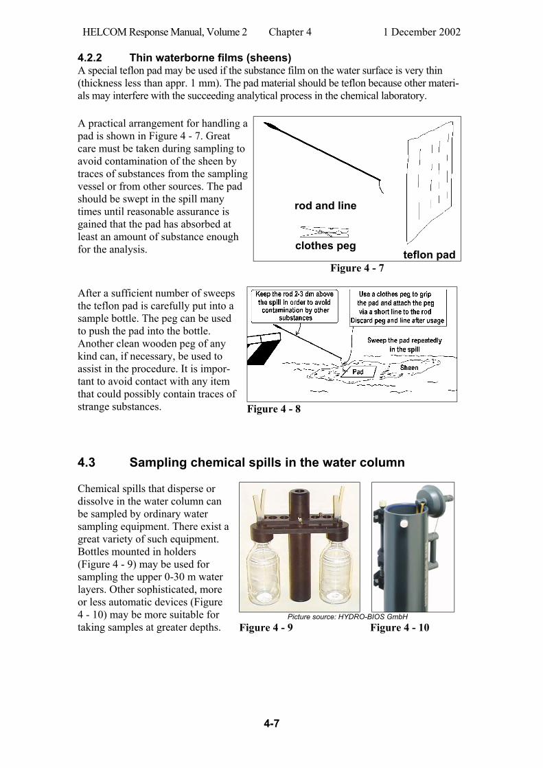
4.3 Sampling chemical spills in the water column
Picture source: HYDRO-BIOS GmbH
Chemical spills that disperse or dissolve in the water column can be sampled by ordinary water sampling equipment. There exist a great variety of such equipment. Bottles mounted in holders (Figure 4 - 9) may be used for sampling the upper 0-30 m water layers. Other sophisticated, more or less automatic devices (Figure 4 - 10) may be more suitable for taking samples at greater depths. Figure 4 - 9 Figure 4 - 10
HELCOM Response Manual, Volume 2 Chapter 4 1 December 2002
4-8
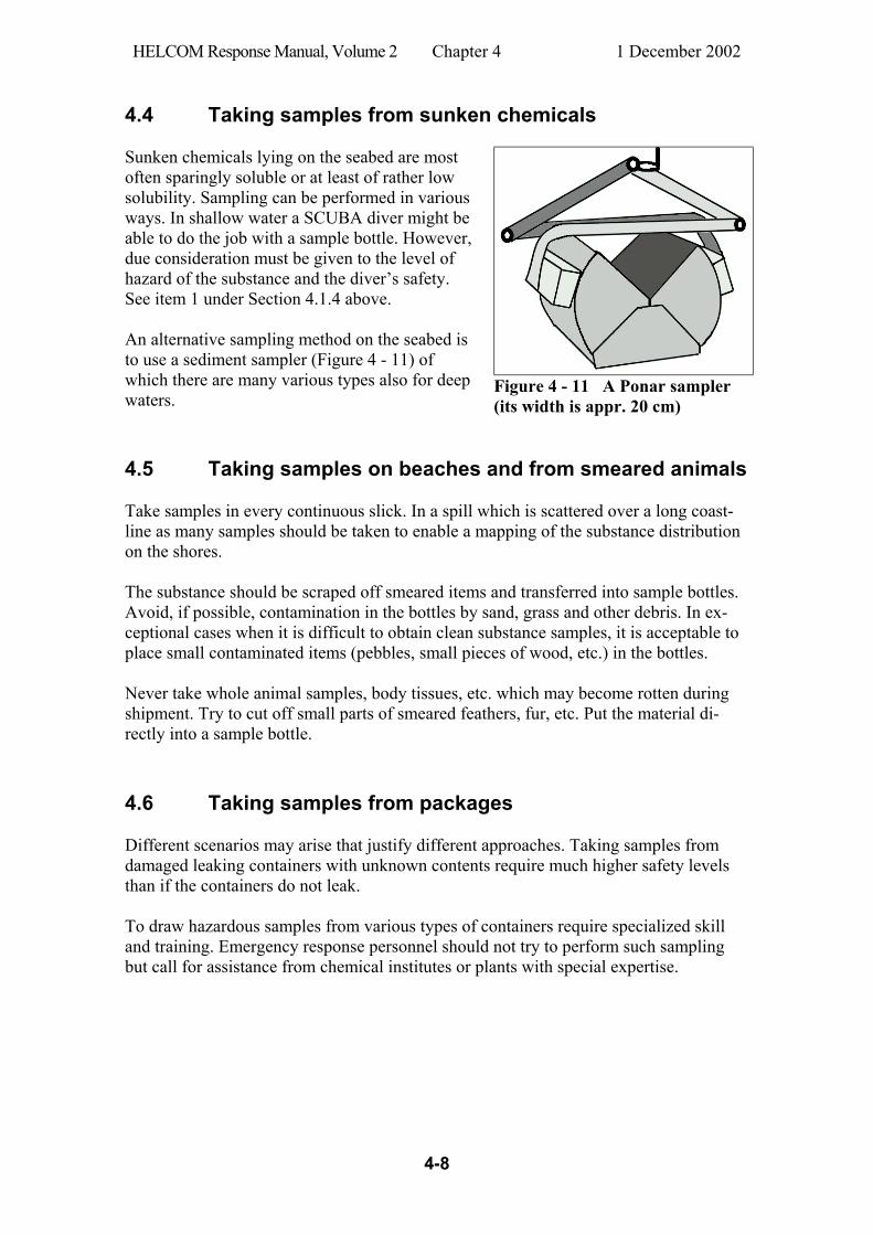
4.4 Taking samples from sunken chemicals Sunken chemicals lying on the seabed are most often sparingly soluble or at least of rather low solubility. Sampling can be performed in various ways. In shallow water a SCUBA diver might be able to do the job with a sample bottle. However, due consideration must be given to the level of hazard of the substance and the diver’s safety. See item 1 under Section 4.1.4 above. An alternative sampling method on the seabed is to use a sediment sampler (Figure 4 - 11) of which there are many various types also for deep waters.
Figure 4 - 11 A Ponar sampler (its width is appr. 20 cm)
4.5 Taking samples on beaches and from smeared animals Take samples in every continuous slick. In a spill which is scattered over a long coast-line as many samples should be taken to enable a mapping of the substance distribution on the shores. The substance should be scraped off smeared items and transferred into sample bottles. Avoid, if possible, contamination in the bottles by sand, grass and other debris. In ex-ceptional cases when it is difficult to obtain clean substance samples, it is acceptable to place small contaminated items (pebbles, small pieces of wood, etc.) in the bottles. Never take whole animal samples, body tissues, etc. which may become rotten during shipment. Try to cut off small parts of smeared feathers, fur, etc. Put the material di-rectly into a sample bottle. 4.6 Taking samples from packages Different scenarios may arise that justify different approaches. Taking samples from damaged leaking containers with unknown contents require much higher safety levels than if the containers do not leak. To draw hazardous samples from various types of containers require specialized skill and training. Emergency response personnel should not try to perform such sampling but call for assistance from chemical institutes or plants with special expertise.
HELCOM Response Manual, Volume 2 Chapter 4 1 December 2002
4-9
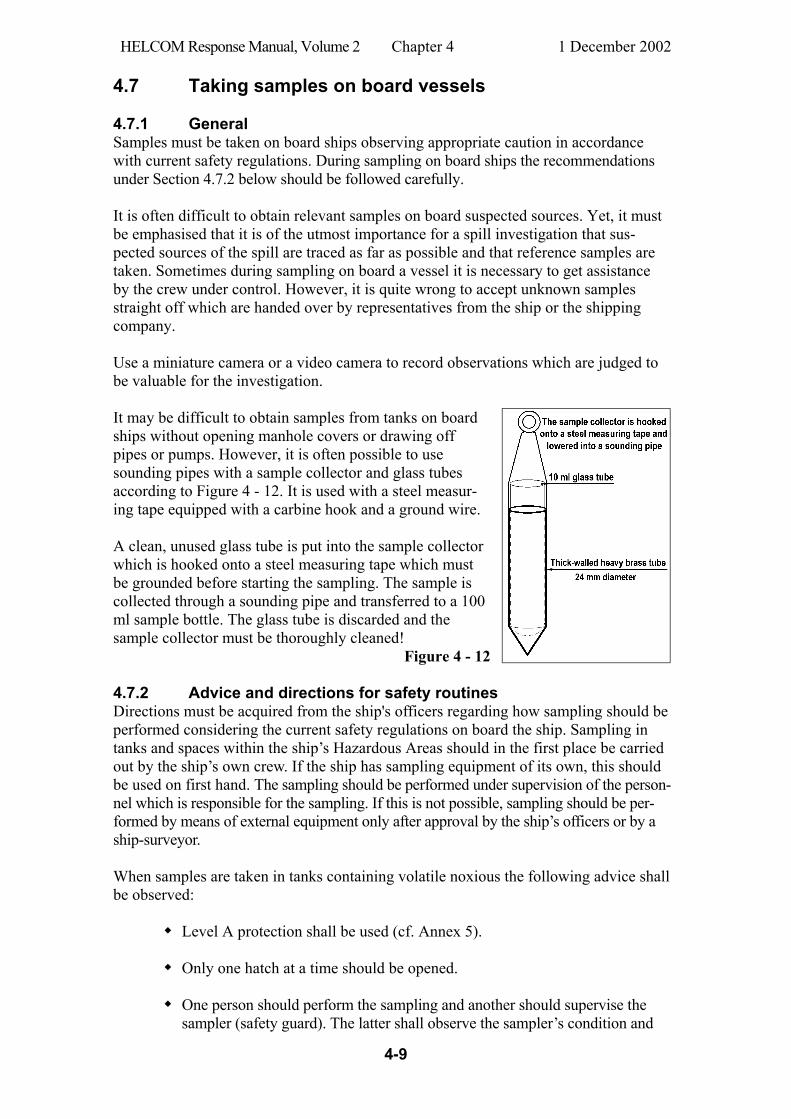
4.7 Taking samples on board vessels 4.7.1 General Samples must be taken on board ships observing appropriate caution in accordance with current safety regulations. During sampling on board ships the recommendations under Section 4.7.2 below should be followed carefully. It is often difficult to obtain relevant samples on board suspected sources. Yet, it must be emphasised that it is of the utmost importance for a spill investigation that sus-pected sources of the spill are traced as far as possible and that reference samples are taken. Sometimes during sampling on board a vessel it is necessary to get assistance by the crew under control. However, it is quite wrong to accept unknown samples straight off which are handed over by representatives from the ship or the shipping company. Use a miniature camera or a video camera to record observations which are judged to be valuable for the investigation. It may be difficult to obtain samples from tanks on board ships without opening manhole covers or drawing off pipes or pumps. However, it is often possible to use sounding pipes with a sample collector and glass tubes according to Figure 4 - 12. It is used with a steel measur-ing tape equipped with a carbine hook and a ground wire. A clean, unused glass tube is put into the sample collector which is hooked onto a steel measuring tape which must be grounded before starting the sampling. The sample is collected through a sounding pipe and transferred to a 100 ml sample bottle. The glass tube is discarded and the sample collector must be thoroughly cleaned!
Figure 4 - 12 4.7.2 Advice and directions for safety routines Directions must be acquired from the ship's officers regarding how sampling should be performed considering the current safety regulations on board the ship. Sampling in tanks and spaces within the ship’s Hazardous Areas should in the first place be carried out by the ship’s own crew. If the ship has sampling equipment of its own, this should be used on first hand. The sampling should be performed under supervision of the person-nel which is responsible for the sampling. If this is not possible, sampling should be per-formed by means of external equipment only after approval by the ship’s officers or by a ship-surveyor. When samples are taken in tanks containing volatile noxious the following advice shall be observed: Level A protection shall be used (cf. Annex 5).
Only one hatch at a time should be opened.
One person should perform the sampling and another should supervise the
sampler (safety guard). The latter shall observe the sampler’s condition and
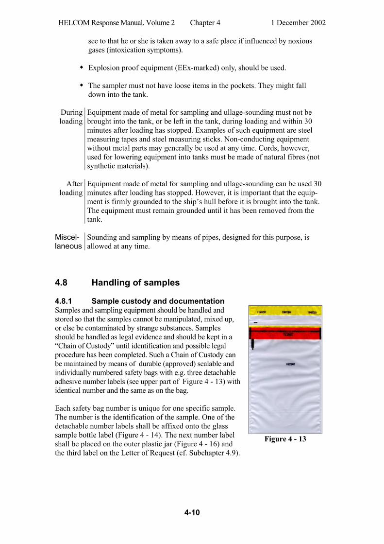
HELCOM Response Manual, Volume 2 Chapter 4 1 December 2002
4-10
see to that he or she is taken away to a safe place if influenced by noxious gases (intoxication symptoms).
Explosion proof equipment (EEx-marked) only, should be used.
The sampler must not have loose items in the pockets. They might fall down into the tank.
During loading
Equipment made of metal for sampling and ullage-sounding must not be brought into the tank, or be left in the tank, during loading and within 30 minutes after loading has stopped. Examples of such equipment are steel measuring tapes and steel measuring sticks. Non-conducting equipment without metal parts may generally be used at any time. Cords, however, used for lowering equipment into tanks must be made of natural fibres (not synthetic materials).
After
loading
Equipment made of metal for sampling and ullage-sounding can be used 30 minutes after loading has stopped. However, it is important that the equip-ment is firmly grounded to the ship’s hull before it is brought into the tank. The equipment must remain grounded until it has been removed from the tank.
Miscel-laneous
Sounding and sampling by means of pipes, designed for this purpose, is allowed at any time.
4.8 Handling of samples 4.8.1 Sample custody and documentation Samples and sampling equipment should be handled and stored so that the samples cannot be manipulated, mixed up, or else be contaminated by strange substances. Samples should be handled as legal evidence and should be kept in a “Chain of Custody” until identification and possible legal procedure has been completed. Such a Chain of Custody can be maintained by means of durable (approved) sealable and individually numbered safety bags with e.g. three detachable adhesive number labels (see upper part of Figure 4 - 13) with identical number and the same as on the bag. Each safety bag number is unique for one specific sample. The number is the identification of the sample. One of the detachable number labels shall be affixed onto the glass sample bottle label (Figure 4 - 14). The next number label shall be placed on the outer plastic jar (Figure 4 - 16) and the third label on the Letter of Request (cf. Subchapter 4.9).
Figure 4 - 13
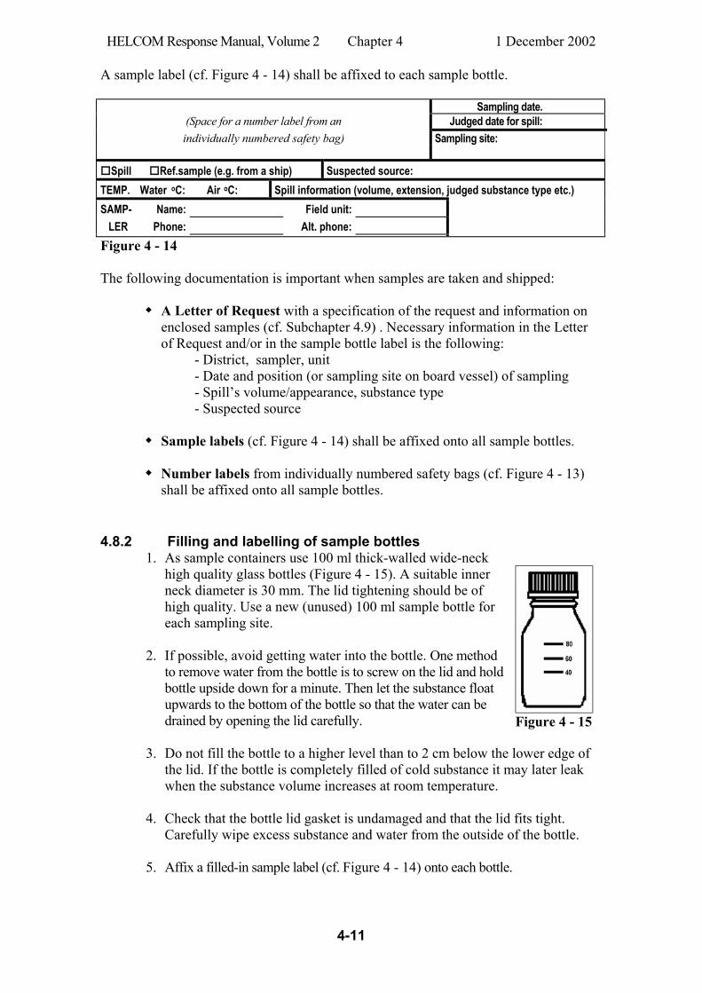
HELCOM Response Manual, Volume 2 Chapter 4 1 December 2002
4-11
A sample label (cf. Figure 4 - 14) shall be affixed to each sample bottle. Sampling date.
(Space for a number label from an Judged date for spill: individually numbered safety bag) Sampling site:
Spill Ref.sample (e.g. from a ship) Suspected source:
TEMP. Water oC: Air oC: Spill information (volume, extension, judged substance type etc.) SAMP- Name: Field unit: LER Phone: Alt. phone: Figure 4 - 14 The following documentation is important when samples are taken and shipped: A Letter of Request with a specification of the request and information on
enclosed samples (cf. Subchapter 4.9) . Necessary information in the Letter of Request and/or in the sample bottle label is the following: - District, sampler, unit - Date and position (or sampling site on board vessel) of sampling - Spill’s volume/appearance, substance type - Suspected source
Sample labels (cf. Figure 4 - 14) shall be affixed onto all sample bottles.
Number labels from individually numbered safety bags (cf. Figure 4 - 13) shall be affixed onto all sample bottles.
4.8.2 Filling and labelling of sample bottles 1. As sample containers use 100 ml thick-walled wide-neck
high quality glass bottles (Figure 4 - 15). A suitable inner neck diameter is 30 mm. The lid tightening should be of high quality. Use a new (unused) 100 ml sample bottle for each sampling site.
2. If possible, avoid getting water into the bottle. One method to remove water from the bottle is to screw on the lid and hold bottle upside down for a minute. Then let the substance float upwards to the bottom of the bottle so that the water can be drained by opening the lid carefully.
Figure 4 - 15
3. Do not fill the bottle to a higher level than to 2 cm below the lower edge of the lid. If the bottle is completely filled of cold substance it may later leak when the substance volume increases at room temperature.
4. Check that the bottle lid gasket is undamaged and that the lid fits tight. Carefully wipe excess substance and water from the outside of the bottle.
5. Affix a filled-in sample label (cf. Figure 4 - 14) onto each bottle.

HELCOM Response Manual, Volume 2 Chapter 4 1 December 2002
4-12
4.8.3 Packing of samples 1. A sample must be packed appropriately before it could be shipped to a labora-
tory for analysis. The sample is usually in either of the following forms: Free substance Sample pad containing substance from spill Smeared item (feather, piece of wood, stone, etc)
2. Allow excess water to drain off from the sample. Check that the sample does not contain animal tissue which might rotten during transport. Insert the sample into a sample bottle. The insertion of a sample pad can be facilitated by pushing the pad with the used clothes peg or a clean peg of any kind. Perform this without touching with fingers or contact with items that might contain disturbing contaminants.
3. Affix a sample label (Figure 4 - 14) onto the sample bottle (Figure 4 - 15) and a number label from an individually numbered safety bag (Figure 4 - 13).
4. Insert the bottle into the safety bag and seal the bag according to the bag’s
instruction.
5. Put the bottle package into a 600 ml plastic jar (Figure 4 - 16) which is used as an outer container. Affix the second number label onto the outside of this jar. Keep the third number label for the Letter of Request (cf. Subchapter 4.9).
Figure 4 - 16
Plastic jar used as an outer con-tainer for the sample bottle which is enclosed in a safety bag.
Figure 4 - 17 Cardboard box (with approval inscription) for shipment of the sample.
6. The samples should be sent immediately to the Sample Co-ordinator. A
quick handling of samples is important. If the transmittal is delayed the samples should be kept under a temperature of less than +4°C. The Sample Co-ordinator watches the continued shipping of the samples.

HELCOM Response Manual, Volume 2 Chapter 4 1 December 2002
4-13
7. The plastic jar with its content of a sample bottle inserted in a sealed safety bag (Figure 4 - 13) should be placed in a cardboard box, before shipment, as shown in Figure 4 - 17.
The whole packaging must be type approved for transport of dangerous goods and the cardboard box must wear an inscription which shows this approval (c.f. Figure 4 - 18)
Figure 4 - 18
(cf. also Sections 6.1.2 and 6.2.2.1). The following table shows the meaning of the codes in Figure 4 - 18:
The United Nations packaging symbol.
4 Type of packaging (4 = box). G Type of packaging material (G = corrugated fibreboard). X Tested for packing groups I, II and III. 1 The maximum gross in kilograms for packagings intended to contain
solids or inner packagings. S Intended for the transport of solids or inner packagings or, for packagings
(other than combination packagings) intended to contain liquids, the hydraulic test pressure which the packaging was shown to withstand in kPa, rounded down to the nearest 10 kPa.
02 The last two digits of the year during which the packaging was manufac-tured.
S The State authorising the allocation of the mark (S = Sweden). SP The name of the manufacturer or other identification of the packaging
specified by the competent authority. 319509 Approval Certificate No.
4.8.4 Shipping of samples The Sample Co-ordinator collects all samples and fills in a Letter of Request which is sent to the laboratory together with the samples. The Sample Co-ordinator should also call in special expertise if required from external institutes or laboratories to assist in the sampling activities. Samples of many chemicals are to be considered as dangerous goods when they are shipped. However, if contained and packaged as described above, they can often be shipped as “limited quantities” which means simpler shipping requirements than for normal dangerous goods. IMDG Code rules as well as local regulations should always be followed.

HELCOM Response Manual, Volume 2 Chapter 4 1 December 2002
4-14
4.9 Example of a form for Request for Analysis Logo- type
Sending Unit Commanding Officer
Date
To: Laboratory name and address Request for analysis Request analysis of the samples listed below Sampling date: No. of samples: No. of pages:
General information (Occurred incident, weather, spill size, suspected source, judged substance type, etc.)
Number label from safety bag
Information which is not
given on the sample bottle *
*Information: Sampler: Name/field unit Spill : Latitude & longitude, and sampling site’s geographical name Ship: Ship name and sample site on board the ship
Signature Name in block letters Rank
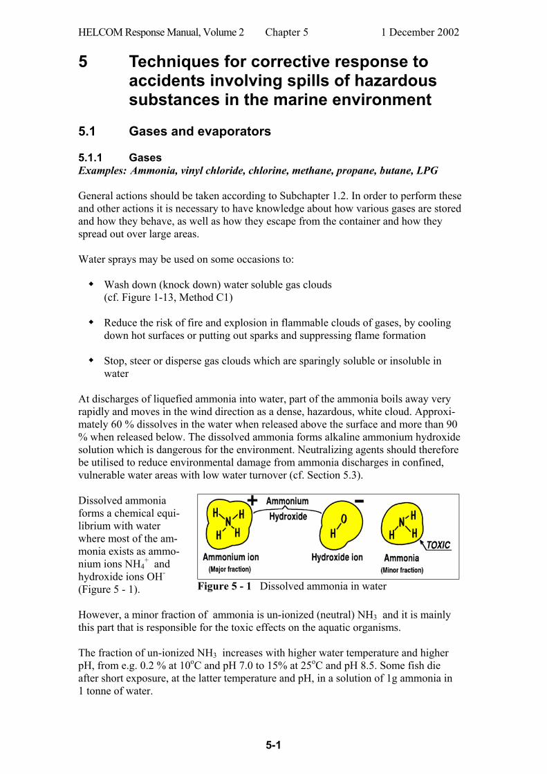
HELCOM Response Manual, Volume 2 Chapter 5 1 December 2002
5-1
5 Techniques for corrective response to accidents involving spills of hazardous substances in the marine environment
5.1 Gases and evaporators 5.1.1 Gases Examples: Ammonia, vinyl chloride, chlorine, methane, propane, butane, LPG General actions should be taken according to Subchapter 1.2. In order to perform these and other actions it is necessary to have knowledge about how various gases are stored and how they behave, as well as how they escape from the container and how they spread out over large areas. Water sprays may be used on some occasions to: Wash down (knock down) water soluble gas clouds
(cf. Figure 1-13, Method C1)
Reduce the risk of fire and explosion in flammable clouds of gases, by cooling down hot surfaces or putting out sparks and suppressing flame formation
Stop, steer or disperse gas clouds which are sparingly soluble or insoluble in water
At discharges of liquefied ammonia into water, part of the ammonia boils away very rapidly and moves in the wind direction as a dense, hazardous, white cloud. Approxi-mately 60 % dissolves in the water when released above the surface and more than 90 % when released below. The dissolved ammonia forms alkaline ammonium hydroxide solution which is dangerous for the environment. Neutralizing agents should therefore be utilised to reduce environmental damage from ammonia discharges in confined, vulnerable water areas with low water turnover (cf. Section 5.3). Dissolved ammonia forms a chemical equi-librium with water where most of the am-monia exists as ammo-nium ions NH4
+ and hydroxide ions OH- (Figure 5 - 1).
Figure 5 - 1 Dissolved ammonia in water
However, a minor fraction of ammonia is un-ionized (neutral) NH3 and it is mainly this part that is responsible for the toxic effects on the aquatic organisms. The fraction of un-ionized NH3 increases with higher water temperature and higher pH, from e.g. 0.2 % at 10oC and pH 7.0 to 15% at 25oC and pH 8.5. Some fish die after short exposure, at the latter temperature and pH, in a solution of 1g ammonia in 1 tonne of water.
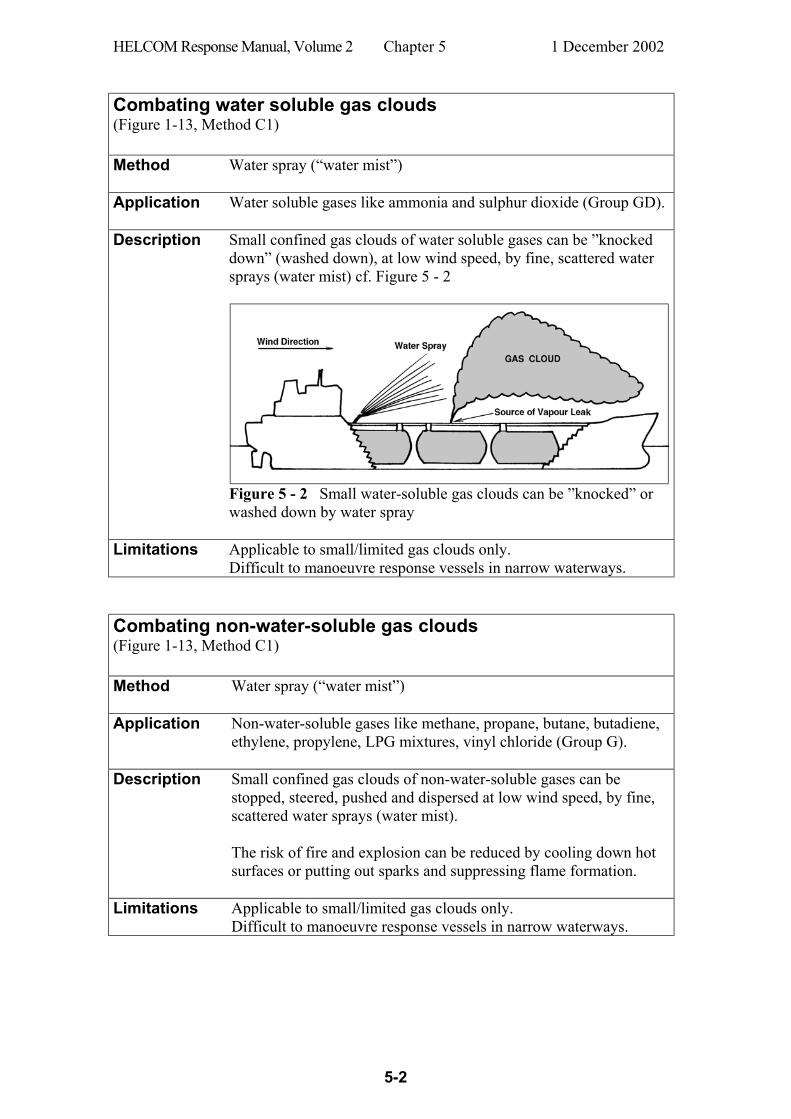
HELCOM Response Manual, Volume 2 Chapter 5 1 December 2002
5-2
Combating water soluble gas clouds (Figure 1-13, Method C1) Method Water spray (“water mist”)
Application Water soluble gases like ammonia and sulphur dioxide (Group GD).
Description
Small confined gas clouds of water soluble gases can be ”knocked down” (washed down), at low wind speed, by fine, scattered water sprays (water mist) cf. Figure 5 - 2
Figure 5 - 2 Small water-soluble gas clouds can be ”knocked” or
washed down by water spray
Limitations Applicable to small/limited gas clouds only. Difficult to manoeuvre response vessels in narrow waterways.
Combating non-water-soluble gas clouds (Figure 1-13, Method C1) Method Water spray (“water mist”)
Application Non-water-soluble gases like methane, propane, butane, butadiene,
ethylene, propylene, LPG mixtures, vinyl chloride (Group G).
Description
Small confined gas clouds of non-water-soluble gases can be stopped, steered, pushed and dispersed at low wind speed, by fine, scattered water sprays (water mist). The risk of fire and explosion can be reduced by cooling down hot surfaces or putting out sparks and suppressing flame formation.
Limitations
Applicable to small/limited gas clouds only. Difficult to manoeuvre response vessels in narrow waterways.
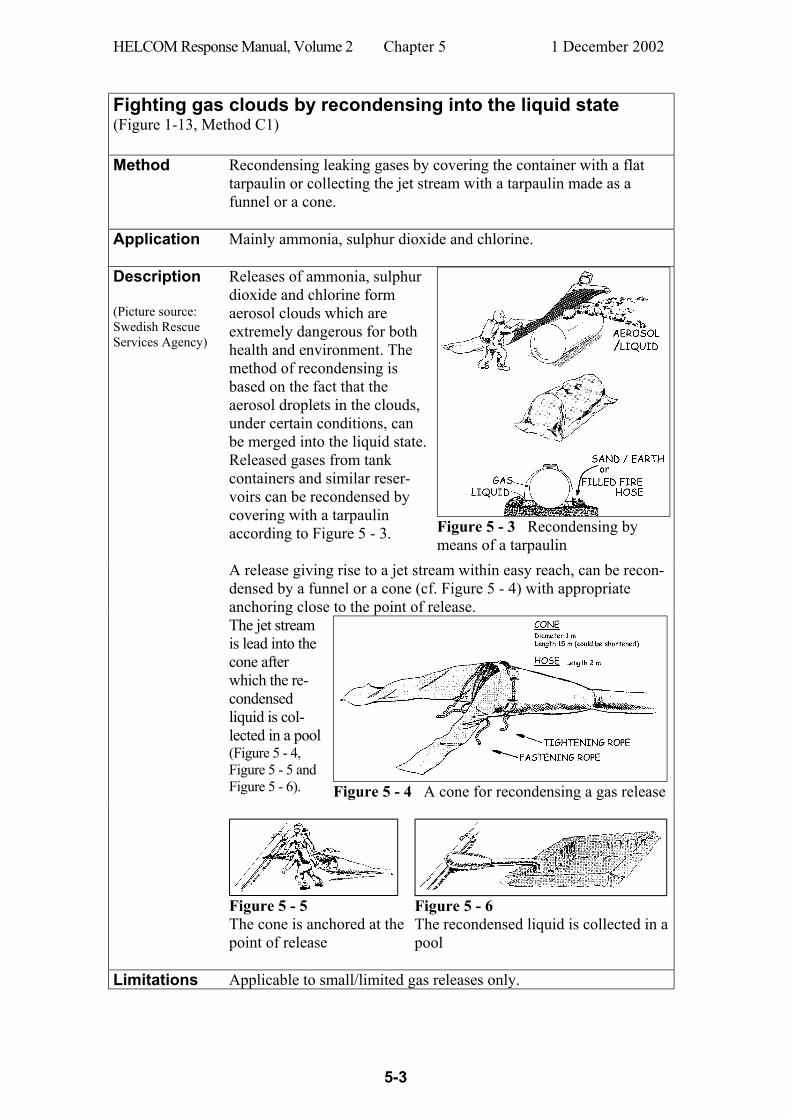
HELCOM Response Manual, Volume 2 Chapter 5 1 December 2002
5-3
Fighting gas clouds by recondensing into the liquid state (Figure 1-13, Method C1) Method Recondensing leaking gases by covering the container with a flat
tarpaulin or collecting the jet stream with a tarpaulin made as a funnel or a cone.
Application Mainly ammonia, sulphur dioxide and chlorine.
Description (Picture source: Swedish Rescue Services Agency)
Releases of ammonia, sulphur dioxide and chlorine form aerosol clouds which are extremely dangerous for both health and environment. The method of recondensing is based on the fact that the aerosol droplets in the clouds, under certain conditions, can be merged into the liquid state. Released gases from tank containers and similar reser-voirs can be recondensed by covering with a tarpaulin according to Figure 5 - 3.
Figure 5 - 3 Recondensing by means of a tarpaulin
A release giving rise to a jet stream within easy reach, can be recon-densed by a funnel or a cone (cf. Figure 5 - 4) with appropriate anchoring close to the point of release.
The jet stream is lead into the cone after which the re-condensed liquid is col-lected in a pool (Figure 5 - 4, Figure 5 - 5 and Figure 5 - 6).
Figure 5 - 4 A cone for recondensing a gas release
Figure 5 - 5 The cone is anchored at the point of release
Figure 5 - 6 The recondensed liquid is collected in a pool
Limitations Applicable to small/limited gas releases only.

HELCOM Response Manual, Volume 2 Chapter 5 1 December 2002
5-4
Supervising a momentary release of a hazardous gas cloud (Figure 1-13, Method M1) Method Supervising a released gas cloud by ships, helicopters and aircraft and
seeding the cloud by ammonia to make it better visible.
Application Large gas clouds at a safe distance from populated areas.
Description Figure 5 - 7 shows an example of using explosives after an accident off the coast of the Netherlands. (Annex 3, accident Sindbad) (Ref. 44). Sunken steel cylinders containing chlorine were broken by explosives and the gas escaped through the water column into the air.
Figure 5 - 7
The rising chlorine gas cloud was strictly super-vised by fully protected personnel. An exclusion zone was established (Figure 5 - 8) and patrolled by ships, helicopters and aircraft. Ammonia gas was released upwind as an indicator gas that seeded the chlorine gas cloud and made it clearly visible as a white smoke over a large area.
Figure 5 - 8
Limitations Very careful planning is necessary with safe distance to populated areas and strict warnings to seafarers and population.
HELCOM Response Manual, Volume 2 Chapter 5 1 December 2002
5-5
5.2 Chemicals that float on the water surface Combating chemical spills that float on the water surface (Figure 1-13, Method C2) Examples: Amyl acetate, butyl acetate, butanol, butyl acrylate, cyclohexanone, dibutyl
phthalate, dioctyl phthalate, dipentene, fish oil, heptane, hexanol, isodeca-nol, olive oil, rape seed oil, tall oil, toluene, turpentine, xylenes
General actions should be taken according to Subchapter 1.2. A spilled chemical that floats on the water surface will spread and form a large contact surface to the air. Depending on its vapour pressure, it may evaporate rapidly and give high gas concentration in the air. When responding to floating chemical spills on the water surface (Ref. 11 and Ref. 12) it is therefore especially important to monitor air concentrations in order to assess fire and explosion risks as well as danger to health. Corrective response actions can be carried out mainly for spills of liquid and solid chemicals, in Group F, that float on the water surface and neither evaporate nor dis-solve. These processes occur very slowly in Group F. Actually, quite a few tanker transported substances belong to Group F but many of these are less hazardous fatty oils. However, even these substances in Group F may sometimes be difficult to combat (pick up). Because of low viscosity some of them may very rapidly distribute over the water surface and form extremely thin layers. These chemicals (Group F) float on water, evaporate very slowly and are sparingly soluble in water. They can be: treated with foam to reduce vaporizing and reduce the risk of fire and explosion treated with sorbents and some other types of treating agents contained by booms (for a short time only, due to chemicals’ generally low viscosity) picked up by recovery equipment (oil skimmers) combated by combinations of the above. During all such response work, special attention must be given to risks of health, fire and explosion. On some occasions, these risks can be reduced by covering the spill with foam as pointed out above. Use of treating agents on a chemical spill on the water surface can restrict its spread and facilitate containment and recovery. There are special sorbents which are capable for chemical spills (Ref. 14 and Ref. 15) but conventional oil spill sorbents can sometimes also be used. Other types of treating agents are so called gelling agents. An example of a gelling agent is the substance which is mixed with gasoline as a ”thickener” when making napalm. However, special gelling agents are needed against floating chemical spills on the water surface. Some gelling agents have been tested, but yet (year 2002) there are no gelling agents available on the market specially designed for chemical spills on the water surface. Some sorbents, shaped like small cubes or pellets made of foam plastic, are used by special systems with broadcaster, harvester as well as regenerator that removes the sorbed sub-stance and makes the sorbent ready for redistribution by the harvester (Ref. 17 and 18).

HELCOM Response Manual, Volume 2 Chapter 5 1 December 2002
5-6
Suppressing vapours from floating spills Method Applying foam by means of fire fighting equipment.
Application Spills of substances that float on the water surface and give off
toxic or flammable vapours.
Description
Confined chemical spills which do not form too large slicks on the water surface can be covered with various types of foams which are normally aimed for fire-fighting (cf. Figure 5 - 9). The foam cover can temporarily suppress vapour formation from the spill and thus reduce the risk of formation of noxious or flammable gas concentrations.
Figure 5 - 9
Limitations
Applicable to relatively small/limited surface chemical slicks only. Different types of foams are applicable to certain groups of chemicals only. Foams reduce the surface tension of the floating spill which will make it more difficult to be recovered by certain skimmers.
The following summary tables (Figure 5 - 10 and Figure 5 - 11) have been prepared by Environment Canada as general guides to the types of foams available and their poten-tial uses. Brief guidelines are presented in the tables as well as references to foam types applicable against spills of specific chemicals. Foam Type Formulation Application Comments Protein-based: 1) Protein hydrolyzed pro-
tein with addi-tives to retard biodegradation
flammable liquid hydrocarbons
low expansion; provide short-term control; good heat resistance, cohesiveness and stability
2) Fluoro-protein
protein plus fluorinated surfactants
flammable liquid hydrocarbons
low expansion; short-term control; resist hydrocarbon saturation and burnback
3) Alcohol alcohol-based protein foam
flammable polar solvents
low expansion; short-term control; stable with some alcohols, ketones esters, etc.
Figure 5 - 10
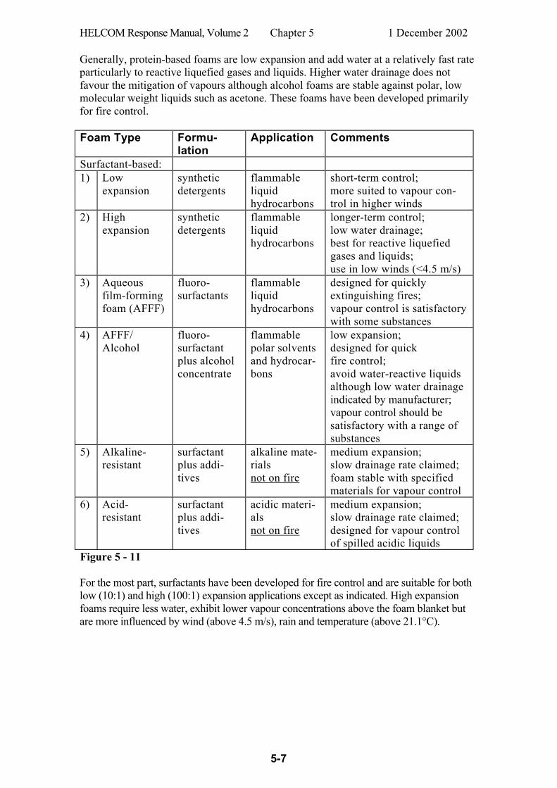
HELCOM Response Manual, Volume 2 Chapter 5 1 December 2002
5-7
Generally, protein-based foams are low expansion and add water at a relatively fast rate particularly to reactive liquefied gases and liquids. Higher water drainage does not favour the mitigation of vapours although alcohol foams are stable against polar, low molecular weight liquids such as acetone. These foams have been developed primarily for fire control. Foam Type Formu-
lation Application Comments
Surfactant-based: 1) Low
expansion synthetic detergents
flammable liquid hydrocarbons
short-term control; more suited to vapour con-trol in higher winds
2) High expansion
synthetic detergents
flammable liquid hydrocarbons
longer-term control; low water drainage; best for reactive liquefied gases and liquids; use in low winds (<4.5 m/s)
3) Aqueous film-forming foam (AFFF)
fluoro-surfactants
flammable liquid hydrocarbons
designed for quickly extinguishing fires; vapour control is satisfactory with some substances
4) AFFF/ Alcohol
fluoro-surfactant plus alcohol concentrate
flammable polar solvents and hydrocar-bons
low expansion; designed for quick fire control; avoid water-reactive liquids although low water drainage indicated by manufacturer; vapour control should be satisfactory with a range of substances
5) Alkaline- resistant
surfactant plus addi-tives
alkaline mate-rials not on fire
medium expansion; slow drainage rate claimed; foam stable with specified materials for vapour control
6) Acid-resistant
surfactant plus addi-tives
acidic materi-als not on fire
medium expansion; slow drainage rate claimed; designed for vapour control of spilled acidic liquids
Figure 5 - 11 For the most part, surfactants have been developed for fire control and are suitable for both low (10:1) and high (100:1) expansion applications except as indicated. High expansion foams require less water, exhibit lower vapour concentrations above the foam blanket but are more influenced by wind (above 4.5 m/s), rain and temperature (above 21.1°C).
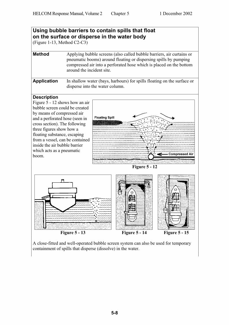
HELCOM Response Manual, Volume 2 Chapter 5 1 December 2002
5-8
Using bubble barriers to contain spills that float on the surface or disperse in the water body (Figure 1-13, Method C2-C3) Method Applying bubble screens (also called bubble barriers, air curtains or
pneumatic booms) around floating or dispersing spills by pumping compressed air into a perforated hose which is placed on the bottom around the incident site.
Application In shallow water (bays, harbours) for spills floating on the surface or disperse into the water column.
Description Figure 5 - 12 shows how an air bubble screen could be created by means of compressed air and a perforated hose (seen in cross section). The following three figures show how a floating substance, escaping from a vessel, can be contained inside the air bubble barrier which acts as a pneumatic boom.
Figure 5 - 12
Figure 5 - 13 Figure 5 - 14 Figure 5 - 15
A close-fitted and well-operated bubble screen system can also be used for temporary containment of spills that disperse (dissolve) in the water.
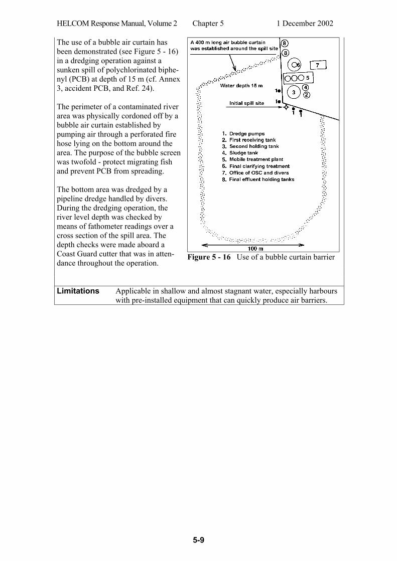
HELCOM Response Manual, Volume 2 Chapter 5 1 December 2002
5-9
The use of a bubble air curtain has been demonstrated (see Figure 5 - 16) in a dredging operation against a sunken spill of polychlorinated biphe-nyl (PCB) at depth of 15 m (cf. Annex 3, accident PCB, and Ref. 24). The perimeter of a contaminated river area was physically cordoned off by a bubble air curtain established by pumping air through a perforated fire hose lying on the bottom around the area. The purpose of the bubble screen was twofold - protect migrating fish and prevent PCB from spreading. The bottom area was dredged by a pipeline dredge handled by divers. During the dredging operation, the river level depth was checked by means of fathometer readings over a cross section of the spill area. The depth checks were made aboard a Coast Guard cutter that was in atten-dance throughout the operation.
Figure 5 - 16 Use of a bubble curtain barrier
Limitations
Applicable in shallow and almost stagnant water, especially harbours with pre-installed equipment that can quickly produce air barriers.
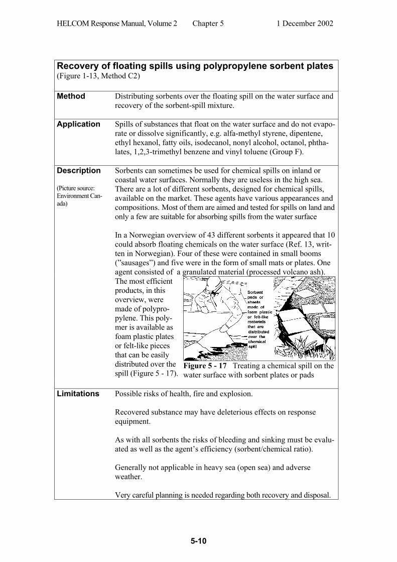
HELCOM Response Manual, Volume 2 Chapter 5 1 December 2002
5-10
Recovery of floating spills using polypropylene sorbent plates (Figure 1-13, Method C2) Method Distributing sorbents over the floating spill on the water surface and
recovery of the sorbent-spill mixture.
Application Spills of substances that float on the water surface and do not evapo-rate or dissolve significantly, e.g. alfa-methyl styrene, dipentene, ethyl hexanol, fatty oils, isodecanol, nonyl alcohol, octanol, phtha-lates, 1,2,3-trimethyl benzene and vinyl toluene (Group F).
Description (Picture source: Environment Can-ada)
Sorbents can sometimes be used for chemical spills on inland or coastal water surfaces. Normally they are useless in the high sea. There are a lot of different sorbents, designed for chemical spills, available on the market. These agents have various appearances and compositions. Most of them are aimed and tested for spills on land and only a few are suitable for absorbing spills from the water surface In a Norwegian overview of 43 different sorbents it appeared that 10 could absorb floating chemicals on the water surface (Ref. 13, writ-ten in Norwegian). Four of these were contained in small booms (”sausages”) and five were in the form of small mats or plates. One agent consisted of a granulated material (processed volcano ash).
The most efficient products, in this overview, were made of polypro-pylene. This poly-mer is available as foam plastic plates or felt-like pieces that can be easily distributed over the spill (Figure 5 - 17).
Figure 5 - 17 Treating a chemical spill on the water surface with sorbent plates or pads
Limitations Possible risks of health, fire and explosion.
Recovered substance may have deleterious effects on response equipment. As with all sorbents the risks of bleeding and sinking must be evalu-ated as well as the agent’s efficiency (sorbent/chemical ratio). Generally not applicable in heavy sea (open sea) and adverse weather. Very careful planning is needed regarding both recovery and disposal.

HELCOM Response Manual, Volume 2 Chapter 5 1 December 2002
5-11
Recovery of floating spills using blankets or pillows packed with powdered sorbents (Figure 1-13, Method C2) Method Distributing blankets/pillows over the floating spill on the water
surface and recovery of the blanket/pillow-spill mixture.
Application Spills of substances that float on the water surface and do not evaporate or dissolve significantly, e.g. alfa-methyl styrene, dipentene, ethyl hexanol, fatty oils, isodecanol, nonyl alcohol, octanol, phthalates, 1,2,3-trimethyl benzene and vinyl toluene (Group F). Description
Picture source: Environment Canada
Some synthetic sorbents for chemical spills are made of rather small particles (around 1 mm in diameter) or even pow-ders. For convenient applica-tion of such sorbents at sea, they are sometimes packed as pillows or in cloth-case as ”blankets” (Ref. 16), see Figure 5 - 18.
Figure 5 - 18
Powdered or granulated sorbents can also be distributed by means of an ejector pipe (cf. Figure 5 - 28). Such a device can facilitate an even spread of the sorbent onto the spill. However, there is a risk that the pipe stops up if the sorbent is fluffy like soft foam plastic. Sometimes the sorbent can be spread onto the spill in a rather unconven-tional way directly from manually held bags, especially if its weight by unit of volume is not too low and the wind speed not too high. Low viscous chemical spills on the water surface spread out rapidly as very thin films. When treating such spills it is therefore necessary to apply high sorbent/chemical ratios in order to obtain efficient absorption. Limitations Possible risks of health, fire and explosion. Recovered substance may have deleterious effects on response equipment. As with all sorbents the risks of bleeding and sinking must be evaluated as well as the agent’s efficiency (sorbent/chemical ratio). Generally not applicable in heavy sea (open sea) and adverse weather. Very careful planning is needed regarding both recovery and disposal.

HELCOM Response Manual, Volume 2 Chapter 5 1 December 2002
5-12
Recovery of floating chemical spills, lumps and small packages using oil trawl systems (Figure 1-13, Method C2) Method Applying certain types of trawls or net bags on floating high viscos-
ity chemical spills or lumps (or small packages).
Application Spills of substances that float on the water surface and form high viscosity layers or lumps that neither evaporate into the air nor disperse into the water (Group F). Also applicable to floating small packages as well as to substances moving in the water body just under the surface.
Description An oil trawl system consists of the guide booms, the entrance net, and detachable trawl bags. It can be very rapidly deployed by means of small work boats. No hydraulic power or heavy mechanical equipment is re-quired - only a simple air blower for inflation of the guide booms, or even less if foam filled booms are used. The trawl bags are attached to the middle of the sweep. The forward movement of the sweep will force the substances or items into the trawl and they will be stopped and collected by the trawl’s masks. The bags can be disconnected and recovered during the operation at sea. Two of the more well-known systems are the ScanTrawl (Figure 5 - 19 and Figure 5 - 20) and the Jackson Trawl.
Figure 5 - 19
Picture source: RO-CLEAN DESMI
Figure 5 - 20
Limitations Possible high risks of health, fire and explosion.
Recovered substance may have deleterious effects on response equipment. Applicable to such members of Property Group F only, that form very high viscosity layers or lumps. However, also applicable to floating small packages.

HELCOM Response Manual, Volume 2 Chapter 5 1 December 2002
5-13
Containment of floating chemical spills by using special barriers in shallow water (Figure 1-13, Method C2) Method Sea Curtain Barrier
Application Leaking substances in shallow water
Description A large leaking container in shal-low water can be boomed to limit the discharge of the chemical. With a conventional boom there is a risk that the leaking substance may flow under the boom. On such occasions a Sea Curtain Barrier can be used according to Figure 5 - 21. It is made of a robust buoyant cushion which holds a barrier stretching down to the bottom where it is held down by an an-chored weight collar (Ref. 36).
Picture source: Environment Canada
Figure 5 - 21 Sea Curtain Barrier which stretches down to the bottom where it anchored.
Limitations Mainly applicable in shallow and almost stagnant water.

HELCOM Response Manual, Volume 2 Chapter 5 1 December 2002
5-14
Recovery of floating chemical spills using oil spill booms and skimmers (Figure 1-13, Method C2) Method Applying certain types of oil containment booms and oil skimmers
on the floating chemical spill.
Application Spills of substances that float on the water surface and do not evaporate or dissolve significantly, e.g. alfa-methyl styrene, dipentene, ethyl hexanol, fatty oils, isodecanol, nonyl alcohol, octanol, phthalates, 1,2,3-trimethyl benzene and vinyl toluene (Group F). Booms The spread of spilled chemicals on the water surface can sometimes be confined by booms. The containment may sometimes be facilitated by pre-treatment with sorbents and similar agents.
Figure 5 - 22
Skimmers Spills of mineral oils on the water surface can be routinely picked up by various types of oil skimmers during the response operation. Floating chemicals, however, may be more difficult to recover from the water surface as their viscosities are often too low and they spread out rapidly and form very thin films on the surface. But it has ap-peared that some chemicals spilled on the water surface actually can be collected, under certain circumstances, by means of oil skimmers (Ref. 18). Sometimes the process could be more easily performed if the spill is pre-treated with certain agents. However, some types of skimmers should not be used on spills mixed with response agents. A few skimmers, suitable for chemical spills, are discussed in the connection with Figure 5 - 23, Figure 5 - 24 and Figure 5 - 25. Limitations Possible high risks of health, fire and explosion.
Recovered substance may have deleterious effects on response equipment. Recovery problems may occur in wave height > 1.5 m and water current > 0.8 kn. Applicable for Property Group F chemicals only (with low solubility and evaporation).
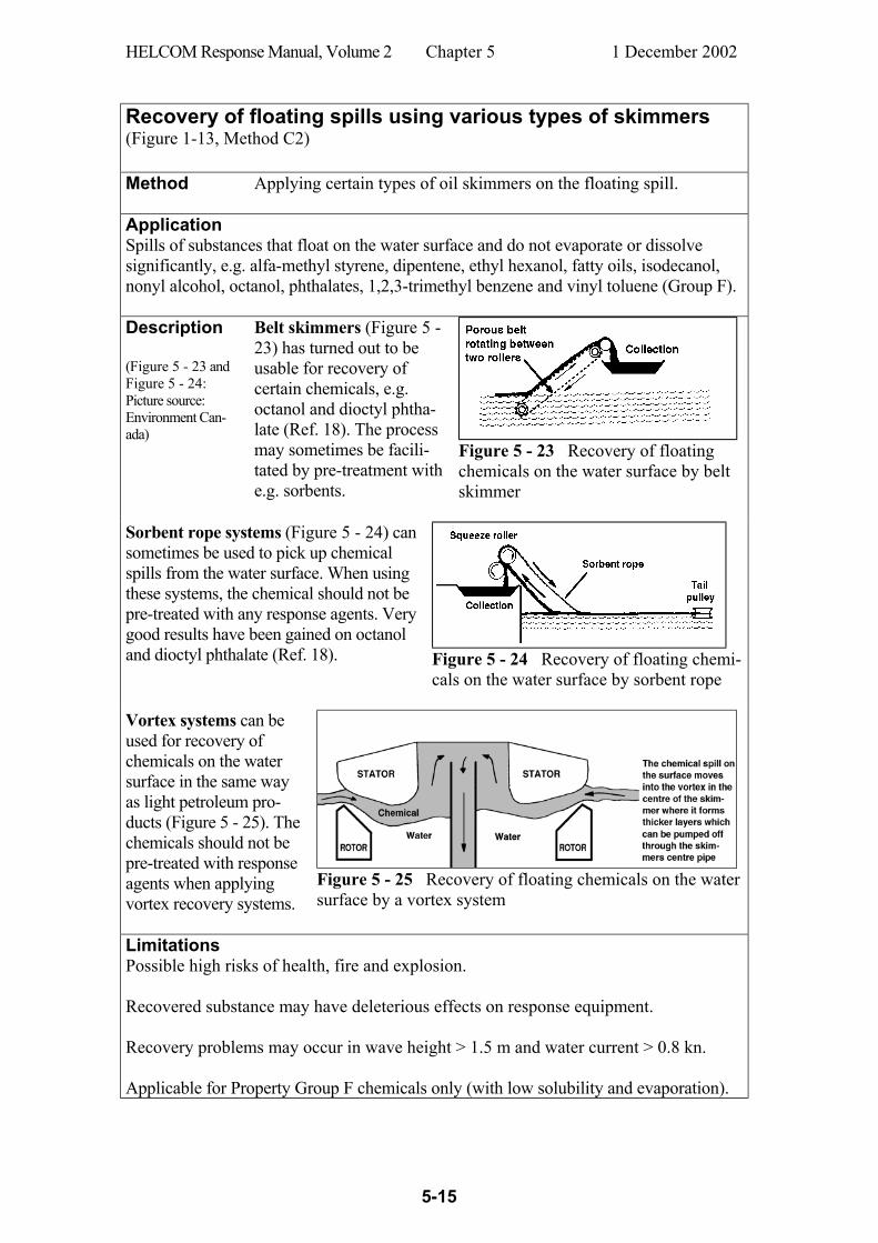
HELCOM Response Manual, Volume 2 Chapter 5 1 December 2002
5-15
Recovery of floating spills using various types of skimmers (Figure 1-13, Method C2) Method Applying certain types of oil skimmers on the floating spill.
Application Spills of substances that float on the water surface and do not evaporate or dissolve significantly, e.g. alfa-methyl styrene, dipentene, ethyl hexanol, fatty oils, isodecanol, nonyl alcohol, octanol, phthalates, 1,2,3-trimethyl benzene and vinyl toluene (Group F). Description (Figure 5 - 23 and Figure 5 - 24: Picture source: Environment Can-ada)
Belt skimmers (Figure 5 - 23) has turned out to be usable for recovery of certain chemicals, e.g. octanol and dioctyl phtha-late (Ref. 18). The process may sometimes be facili-tated by pre-treatment with e.g. sorbents.
Figure 5 - 23 Recovery of floating
chemicals on the water surface by belt skimmer
Sorbent rope systems (Figure 5 - 24) can sometimes be used to pick up chemical spills from the water surface. When using these systems, the chemical should not be pre-treated with any response agents. Very good results have been gained on octanol and dioctyl phthalate (Ref. 18).
Figure 5 - 24 Recovery of floating chemi-cals on the water surface by sorbent rope
Vortex systems can be used for recovery of chemicals on the water surface in the same way as light petroleum pro-ducts (Figure 5 - 25). The chemicals should not be pre-treated with response agents when applying vortex recovery systems.
Figure 5 - 25 Recovery of floating chemicals on the water surface by a vortex system
Limitations Possible high risks of health, fire and explosion. Recovered substance may have deleterious effects on response equipment. Recovery problems may occur in wave height > 1.5 m and water current > 0.8 kn. Applicable for Property Group F chemicals only (with low solubility and evaporation).
HELCOM Response Manual, Volume 2 Chapter 5 1 December 2002
5-16
5.3 Chemicals that dissolve in water Combating chemical spills that dissolve in water (Figure 1-13, Method C3) Examples: Acetone, ethanol, phosphoric acid, glycols, isopropanol, methanol,
methyl ethyl ketone, monoethyl amine, sodium hydroxide solution, propionic acid, propylene oxide, sulphuric acid, acetic acid, ammonium hydroxide (from dissolved ammonia)
General actions should be taken according to Subchapter 1.2. A spilled chemical, that dissolves in water, will form a growing ”cloud” in the water body. It is important to monitor the concentration gradients in the cloud to track the chemicals’ spread and drift in order to judge the hazards for the environment, fishery, recreational areas, fresh water intakes, etc. Chemical spills that dissolve in shallow water may sometimes sea be mixed in with vari-ous treating agents (useless in open) in order to reduce deleterious effects on humans and the environment (Ref. 19, Ref. 20 and Ref. 21). Examples of such treating agents are:
Neutralizing agents Activated carbon
Oxidizing agents Reduction agents
Complexing agents Ion exchangers
The use of neutralising agents is described as a standard method on next page. A reduction agent, ferrosulphate, has once been used in an accident to treat leaking chromium compounds from a sunken ship north of the Island of Öland in the Baltic Sea. The treatment was performed simply by emptying bags of altogether 11 tonnes of ferro-sulphate from a surface vessel so that the agent descended and spread over the sunken ship on the bottom at 17 m depth (c.f. Annex 3 “Viggo Hinrichsen”). Examples of other treating agents are flocculation agents (for fine particle dispersions) and gelling agents (for floating slicks before they dissolve). Agents which just absorb the spilled substance and settle on the seabed (e.g. activated carbon and flocculation agents) should be used with care and only in consultation with environmental expertise. Flocculation agents, gelling agents, activated carbon, complexing agents and ion ex-changers can also be used for treatment of mixtures of chemicals and water that have been recovered from a spill site and pumped into barges or other intermediate storing containers (examples in Ref. 23, Ref. 24 and Ref. 25). Activated carbon is often used in this way and is a well-known, efficient agent for absorption of many different organic chemicals. Activated carbon can also, according to some investigations, be used suc-cessfully for chemical spills in flowing waters (Ref. 26, Ref. 27, Ref. 28 and Ref. 29) while other sources (Ref. 30) maintain that activated carbon is not suitable for direct treatment of chemical spills in the environment. The method of adding treating agents to dispersed chemical spills in the water body can be used especially against substances belonging to Group D, but sometimes also against other chemicals (the Groups GD, ED, FED, FD and SD).

HELCOM Response Manual, Volume 2 Chapter 5 1 December 2002
5-17
Containment of dissolving chemical spills in shallow water by using barriers (Figure 1-13, Method C3) Method Sea Curtain Barrier
Application Substances that dissolve in shallow water bodies
Description Field trials with a Sea Curtain Bar-rier have been performed by US Environmental Protection Agency at about 8 m depth. A prototype device was tested that effectively contained a spill of rodamine (Ref. 36).
Picture source: US Coast Guard
Figure 5 - 26 Anchoring of a curtain barrier The anchoring of the curtain barrier requires a special technique as the barrier may be subjected to very strong stress from water currents. Anchors are shot down into the bottom by special guns. The proce-dure is shown by Figure 5 - 26 and Figure 5 - 27.
Picture source: US Coast Guard
Figure 5 - 27 Anchoring of a curtain barrier
Limitations Mainly applicable in shallow and almost stagnant water.

HELCOM Response Manual, Volume 2 Chapter 5 1 December 2002
5-18
Treating dissolving spills in the water body with neutralizing agents (Figure 1-13, Method C3) Method Adding neutralizing agents to a spill site in the water body.
Application Spills of acids and bases that dissolve when spilled into the water and
change its pH significantly. Examples are ammonium hydroxide, fluo-silicic acid, phosphoric acid, sodium hydroxide solution, propionic acid, nitric acid, sulphuric acid and acetic acid (Group D)
Description Releases of acids and bases in streams, creeks and rivers have, on some occasions, turned out to give devastating ecological effects even if the volumes are relatively small. The ex-planation to the serious impacts is that such a spill, if it is momentary or occurs in a short time, forms a relatively concentrated ”cloud” that moves downstream and damages or destroys the life in the water all along its course. Spills of acids and bases in confined water areas should therefore be quickly located, mapped, and then treated with neutralizing agents. The following neutralizing agents have turned out to be suitable choices (Ref. 22): For spills of acids: For spills of bases: Sodium acid carbonate
(sodium bicarbonate, NaHCO3) Sodium dihydrogen phosphate (monosodium phosphate, NaH2PO4)
Treating agents should be used in consultation with an appropriate environmental protection authority, that should also advise on dosage. The agent can be spread out by means of ejector pipes (Figure 5 - 28) or directly from bags. If there is any uncertainty about dosage, the following is recommended: Find out the weight of spilled chemicals. The theoretically correct dosage is approximately the double amount of neutralizing agent. Apply an overdose of 50 per cent and dis-tribute in a suitable way over the whole spill site. The pH should be monitored continuously.
Figure 5 - 28 Use of an ejector pipe for distribution of a treating agent
At discharges of liquefied ammonia into water, part of the ammonia boils away very rapidly. The rest of the discharge dissolves in the water body and forms alkaline am-monium hydroxide solution which is dangerous for the environment. Neutralizing agents should therefore be utilised to reduce environmental damage from ammonia discharges in confined, vulnerable water areas with low water turnover. Limitations
Not feasible in open sea, deep waters, strong currents, high wind speed, high see state or adverse weather. When treating very large spills there might be problems to acquire, transport and handle large volumes of the treating agents.

HELCOM Response Manual, Volume 2 Chapter 5 1 December 2002
5-19
Using a mobile treatment unit to remove dissolved spills in confined water bodies (Figure 1-13, Method C3) Method
Using the US Environmental Protection Agency’s Mobile Hazardous Material Spills Treatment Trailer.
Application Dissolved or dispersed substances in dams, ponds, water supplies and small lakes.
Description The US Environmental Protection Agency (EPA) has used a trailer-borne self-contained water treatment system (cf. Figure 5 - 29) to remove several classes of hazardous materi-als from water. The trailer can be rapidly carried by road to distant sites and can treat 0.8 m³ contaminated water per minute. It has the following data: Length 15 m Capacity: 1100 m³/24 hr Width 2.5 m Gasoline-powered Generator: 100 kW Weight 43 tons Cost: $ 250,000 The main features of the trailer are: • three mixed-media filters for removal of suspended or precipitated material • three activated carbon columns for the removal of many soluble organic chemicals
The system also includes: • A 60 m³ deployable portable tank for flocculation, precipitation or neutralization • Several 11 m³ pillow tanks for effluent or sludge storage • Hoses and pumps to allow positioning the unit up to 100 m from the site After on accident the unit was used to purify 2,300 m3 of watery sludge. Two hundred drums of PCB-contaminated mud was collected and later carried to a disposal site (cf. Annex 3, accident PCB, and Ref. 24).
Picture source: US Environmental Protection Agency
Figure 5 - 29 A mobile chemical treatment unit Limitations Mainly applicable for contaminated water in dams, ponds, water
supplies and small lakes.

HELCOM Response Manual, Volume 2 Chapter 5 1 December 2002
5-20
5.4 Chemicals that sink to the bottom Combating chemical spills that sink to the bottom (Figure 1-13, Method C4) General actions should be taken according to Subchapter 1.2. Discharges of chemicals that sink to the bottom can heavily contaminate the impacted bottom sediments. Careful planning should be done, on such occasions, for the decon-tamination work. A sophisticated system may be needed to take care of and clean the contaminated sediments (Ref. 23 and Ref. 31, cf. also Annex 3 “Testbank”). Sunken spills on the bottom can be recovered by different kinds of dredging techniques and there are various types of suitable dredges (Ref. 32, Ref. 33, Ref. 34, Ref. 35, Ref. 36 and Ref. 37). Different dredges are more or less suitable for removal of chemicals from the bottom. There are three main types of dredges according to Figure 5 - 30, of which airlift pneumatic dredges should be mentioned as successful examples used in well-documented accidents (Ref. 23 and Ref. 38, cf. also Annex 3 “Testbank”). Type Examples Mechanical dredges Bucket Ladder, Clamshell, Dipper Hydraulic dredges Plain Suction
Dustpan Cutterhead
Hopper Mudcat PIJESP (Peripheral Injector Jet Suction Pump)
Pneumatic dredges Pneuma, Airlift Figure 5 - 30
Appropriate safety precautions should always be taken in all dredging operations of sunken hazardous materials. Divers surveying the operation should be aware of the risk of chemicals as well as mechanical hazards. Personnel working at the surface must wear relevant personal protective gear. Recovered hazardous materials or contaminated mud may pose severe hazard and should be treated with great precaution with regard to the properties of the chemicals involved. If the recovered material is transferred to barges it may be necessary to cover the barges tightly in order to protect human and the environment. Some dredges have storage tanks of their own. Such tanks should only be used for contaminated mud under the following conditions: If the storage tank is approved for the chemical(s) involved
(the same rules as for a chemical tankers)
If a monitoring system is installed
If the accommodation is sheltered or gas-tight
If fast evacuation of crew is possible
If the crew wear appropriate Personal Protective Equipment (PPE) during the operation

HELCOM Response Manual, Volume 2 Chapter 5 1 December 2002
5-21
Recovery of sunken spills from the seabed using mechanical dredging systems (Figure 1-13, Method C4) Method Dredging
Application Solid or semi-solid chemicals which are heavier than water (sink to
bottom) e.g. phenol, sulphur, creosote, coal tar, tall oil resin and some biocides (danger of scattering of biocides) (Group S and SD).
Description
Clamshell and Dipper dredges (Figure 5 - 31 and Figure 5 - 32) are the most unsophisticated types of equipment that can be used in shallow waters with the machinery placed on a barge, or nearby quay or shore. Such an equipment was used in 1973 in Gothenburg, Sweden, to dredge sunken phenol from the bottom of the harbour dock (cf. Annex 3, accident Phenol).
Figure 5 - 31 Mechanical dredge of Clamshell type
Picture source: Hand et al. 1978
Figure 5 - 32 Mechanical dredge of Dipper type
Picture source: Hand et al. 1978
Other types of mechanical dredges (e.g. Bucket Ladder) are normally
not suitable for removal of sunken chemicals. They cause too much turbulence and run the risk of spreading the spill over larger areas.
Advantages Rather simple equipment to handle. Often easily available.
Limitations Feasible in shallow water only. There is a great risk of scattering the sunken chemical over larger areas.
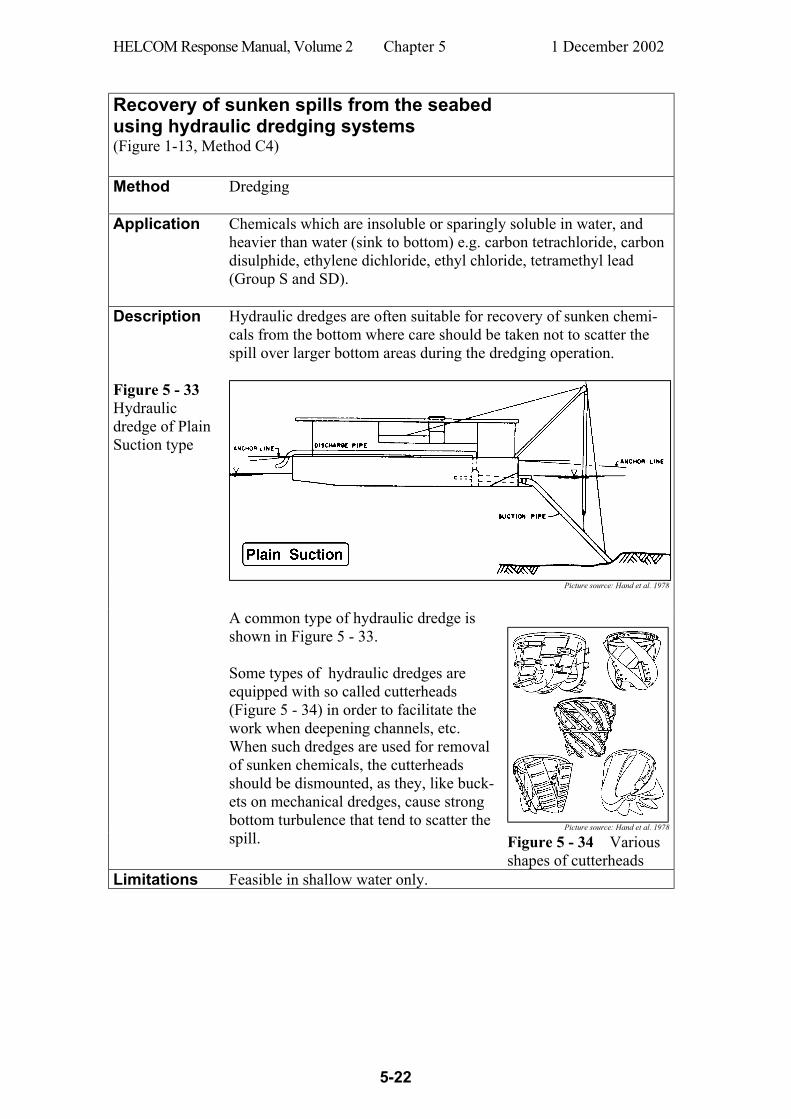
HELCOM Response Manual, Volume 2 Chapter 5 1 December 2002
5-22
Recovery of sunken spills from the seabed using hydraulic dredging systems (Figure 1-13, Method C4) Method Dredging
Application Chemicals which are insoluble or sparingly soluble in water, and
heavier than water (sink to bottom) e.g. carbon tetrachloride, carbon disulphide, ethylene dichloride, ethyl chloride, tetramethyl lead (Group S and SD).
Description
Hydraulic dredges are often suitable for recovery of sunken chemi-cals from the bottom where care should be taken not to scatter the spill over larger bottom areas during the dredging operation.
Figure 5 - 33 Hydraulic dredge of Plain Suction type
Picture source: Hand et al. 1978
Picture source: Hand et al. 1978
A common type of hydraulic dredge is shown in Figure 5 - 33. Some types of hydraulic dredges are equipped with so called cutterheads (Figure 5 - 34) in order to facilitate the work when deepening channels, etc. When such dredges are used for removal of sunken chemicals, the cutterheads should be dismounted, as they, like buck-ets on mechanical dredges, cause strong bottom turbulence that tend to scatter the spill. Figure 5 - 34 Various
shapes of cutterheads Limitations Feasible in shallow water only.
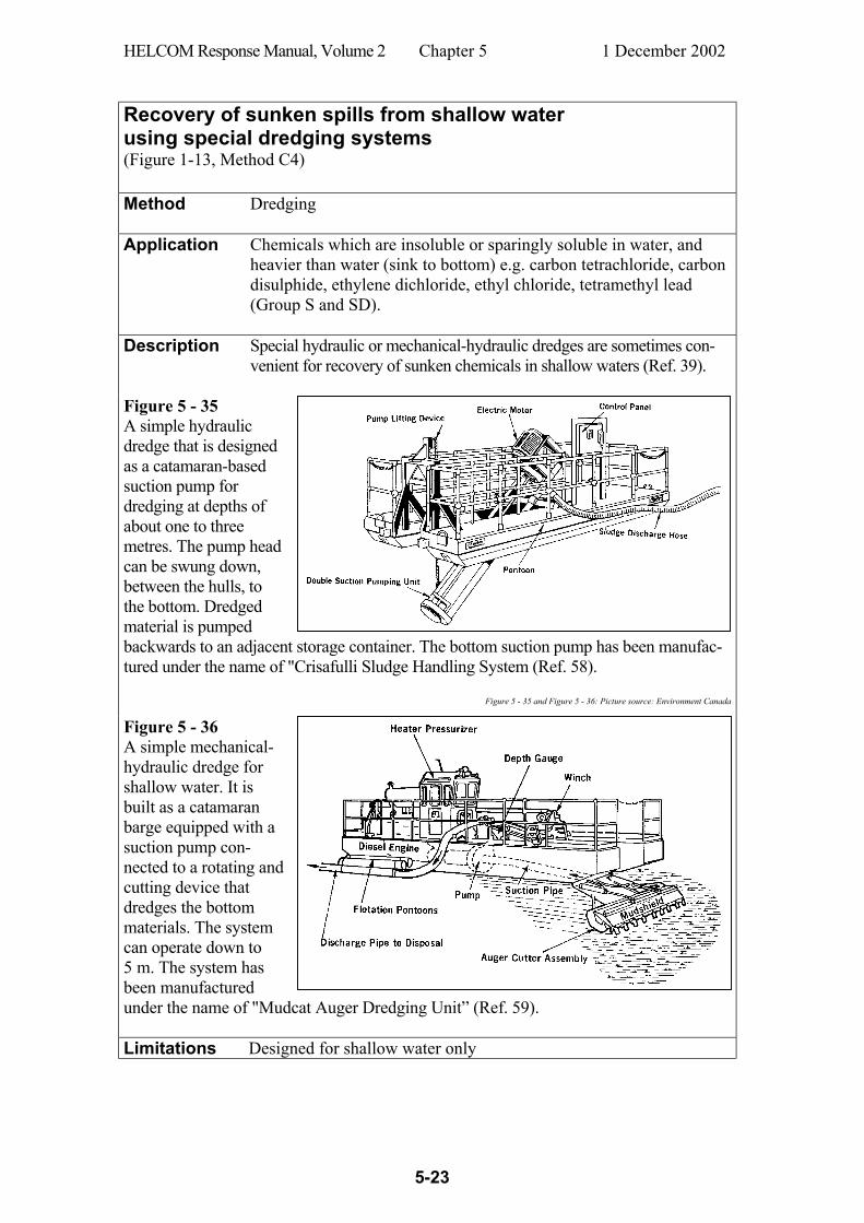
HELCOM Response Manual, Volume 2 Chapter 5 1 December 2002
5-23
Recovery of sunken spills from shallow water using special dredging systems (Figure 1-13, Method C4) Method Dredging
Application Chemicals which are insoluble or sparingly soluble in water, and
heavier than water (sink to bottom) e.g. carbon tetrachloride, carbon disulphide, ethylene dichloride, ethyl chloride, tetramethyl lead (Group S and SD).
Description
Special hydraulic or mechanical-hydraulic dredges are sometimes con-venient for recovery of sunken chemicals in shallow waters (Ref. 39).
Figure 5 - 35 A simple hydraulic dredge that is designed as a catamaran-based suction pump for dredging at depths of about one to three metres. The pump head can be swung down, between the hulls, to the bottom. Dredged material is pumped backwards to an adjacent storage container. The bottom suction pump has been manufac-tured under the name of "Crisafulli Sludge Handling System (Ref. 58).
Figure 5 - 35 and Figure 5 - 36: Picture source: Environment Canada
Figure 5 - 36 A simple mechanical-hydraulic dredge for shallow water. It is built as a catamaran barge equipped with a suction pump con-nected to a rotating and cutting device that dredges the bottom materials. The system can operate down to 5 m. The system has been manufactured under the name of "Mudcat Auger Dredging Unit” (Ref. 59). Limitations Designed for shallow water only

HELCOM Response Manual, Volume 2 Chapter 5 1 December 2002
5-24
Recovery of sunken spills from the seabed using a simple suction system (Figure 1-13, Method C4) Method Dredging by a suction pump system (Peripheral Injector Jet Suction
Pump PIJESP)
Application Chemicals which are insoluble or sparingly soluble in water, and heavier than water (sink to bottom) e.g. carbon tetrachloride, carbon disulphide, ethylene dichloride, ethyl chloride, tetramethyl lead (Group S and SD). This system is especially suitable if the spill is scattered over the seabed and the suction head must be held and manoeuvred by a diver.
Description Figure 5 - 37, Figure 5 - 38 and Figure 5 - 39 shows a PIJESP which has been supplement-ed, inside the head, by nozzles pointing in-wards. With this system it is possible to add e.g. pressurized hot-water to facilitate dredg-ing of lumpy or high viscous chemicals. It has been used under winter conditions for removal of sunken oil after an accident.
Figure 5 - 37 A PIJESP which can be operated
by divers
Figure 5 - 38 A diver holding a PIJESP
Figure 5 - 39 A close-up view of the PIJESP’s suction head showing the nozzles mounted inside the mouth pointing in-wards.
Limitations The divers’ full protective equipment may interfere with the manoeu-
vring of the PIJESP when recovering a sunken hazardous material spill.
HELCOM Response Manual, Volume 2 Chapter 5 1 December 2002
5-25
Recovery of sunken spills from the seabed using a pneumatic dredge (Figure 1-13, Method C4) Method Dredging by a pneumatic dredge.
Application Chemicals which are insoluble or sparingly soluble in water, and
heavier than water (sink to bottom) e.g. carbon tetrachloride, carbon disulphide, ethylene dichloride, ethyl chloride, tetramethyl lead (Group S and SD).
Description Figure 5 - 40 shows a pneumatic dredge that operates with a sub-mersible air-driven pump which is supplied with air from a compres-sor on the barge. The pump is designed with three cylinders that alternately fills, by the hydrostatic pressure, with sediment during the dredging operation. The sediment is then forced upwards to the sur-face by the compressed air. The advantage of this technique, com-pared to hydraulic dredging, is that 1) the mud does not need to be fluid but may contain up to 70 % dry matter, and 2) the method has no limitation regarding working depth. The type of pneumatic dredge showed in Figure 5 - 40 was used, on one occasion, in an American river for removing sunken PCB at a depth of 15 m. A smaller pneu-matic dredge is shown in Figure 5 - 41 and Figure 5 - 42.
Figure 5 - 40 Pneumatic dredge of ”Pneuma” type Picture source: Hand et al.
Limitations Pneumatic dredges have in theory no depth limitations but the strong
suction force at great depths (> 50 m) cause violent dredge mouth movements which obstruct proper dredging and pose great risks for divers working close.
HELCOM Response Manual, Volume 2 Chapter 5 1 December 2002
5-26
Recovery of sunken spills from the seabed using a simple pneumatic dredge (Airlift) (Figure 1-13, Method C4) Method Dredging by a pneumatic dredge (Airlift)
Application Chemicals which are insoluble or sparingly soluble in water, and
heavier than water (sink to bottom) e.g. carbon tetrachloride, carbon disulphide, ethylene dichloride, ethyl chloride, tetramethyl lead (Group S and SD). Airlift has turned out to be a very useful type of dredge for recovery of sunken chemicals in water depths down to 10-20 metres. The system has no theoretical depth limitation. The dredging efficiency is better the deeper the water is. Airlifts are sometimes used in the North Sea for dredging stones down to depths of 60 - 70 m. But it is unlikely that airlifts could be used operationally at such depths for dredging sunken chemicals.
Description
Figure 5 - 41
A small pneumatic dredge (airlift)
Airlift is a simple pneumatic dredge which, in principle, is just a tube extending from the support vessel down to the bottom (Figure 5 - 41). A compressor on the support vessel transfers compressed air, in a separate hose, either down to the head of the main tube, or to an inlet manifold, placed somewhere on the tube. The rising air expands
HELCOM Response Manual, Volume 2 Chapter 5 1 December 2002
5-27
and causes a strong current in the tube which is stronger the greater the working depth is.
Arne Borlin 1977
Practical arrangement
Figure 5 - 42 shows a suit-able system for practical operation of an airlift sys-tem. A surface vessel (barge etc.) is positioned above the dredging site and an air compressor on board the vessel supplies the diver with compressed air at the airlift mouth. The barge can also receive the dredged material in built-in tanks or in separate containers on board.
Figure 5 - 42 Practical arrangement for operating an airlift system. To achieve greater mobility the diver can work with a flexible hose attached to the airlift mouth.
The diver operates the airlift tube, which is stabilized by a weight to neutralize the strong lateral movements that strengthen with increas-ing working depth. The diver can also adjust the compressed air flow by a knob on the tube.
Limitations A practical limiting factor is the compressor which has to be bigger
(and more expensive) the greater the depth is. Furthermore, the tube is more difficult to manoeuvre at great depths (> 20 m), as the lateral forces become stronger. The risks for divers are also greater at in-creasing depths because of the enormous suction forces close to the airlift head. The divers’ full protective equipment may interfere with the ma-noeuvring of the Airlift when recovering a sunken hazardous mate-rial spill.
Experiences An airlift was used with success after a ship accident in 1980 where 16 tonnes of pentachlorophenol (PCP) was dredged from the bottom of Mississippi River (Ref. 23; also cf. Annex 3 “Testbank”).
HELCOM Response Manual, Volume 2 Chapter 5 1 December 2002
5-28
Controlled evacuation of cargo from a sunken barge using a simple pneumatic pump (Airlift) Method Cargo pumping by a pneumatic dredge (Airlift)
Application A special application of an airlift system was demonstrated in the
Mississippi River in 1988 (cf. Annex 3, “Sunken barge”) at a re-sponse operation where a sunken barge with sulphuric acid was emptied (Figure 5 - 43) (Ref. 38).
Description An air-lift tube is lowered into the barge (cf. Figure 5 - 43) and compressed air is delivered by an air compressor. By letting the air bubble upwards through the acid inside the tube the acid is drawn from the tank and slowly discharged into the water. The rate of the discharge is easily controlled by altering the rate of introduced air in the system.
Figure 5 - 43 A sunken barge with a cargo of concentrated sulphuric acid was emptied by an airlift dredge and the acid was very slowly released into the Mississippi River under strict supervision of downstream pH-levels. Limitations Feasible for soluble chemicals only.
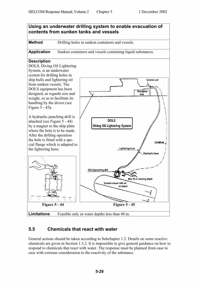
HELCOM Response Manual, Volume 2 Chapter 5 1 December 2002
5-29
Using an underwater drilling system to enable evacuation of contents from sunken tanks and vessels Method Drilling holes in sunken containers and vessels.
Application Sunken containers and vessels containing liquid substances.
Description DOLS, Diving Oil Lightering System, is an underwater system for drilling holes in ship hulls and lightering oil from sunken vessels. The DOLS equipment has been designed, as regards size and weight, so as to facilitate its handling by the divers (see Figure 5 - 45). A hydraulic punching drill is attached (see Figure 5 - 44) by a magnet to the ship plate where the hole is to be made. After the drilling operation the hole is fitted with a spe-cial flange which is adapted to the lightering hose.
Figure 5 - 44 Figure 5 - 45
Limitations Feasible only in water depths less than 40 m. 5.5 Chemicals that react with water General actions should be taken according to Subchapter 1.2. Details on some reactive chemicals are given in Section 1.3.2. It is impossible to give general guidance on how to respond to chemicals that react with water. The response must be planned from case to case with extreme consideration to the reactivity of the substance.
HELCOM Response Manual, Volume 2 Chapter 5 1 December 2002
5-30
5.6 Miscellaneous disposal methods General Disposal processes include methods by which chemicals and chemical-contaminated wastes are disposed of or finally eliminated. Such methods are normally applied after the response phase. A few techniques are utilized at the site of accident, but most of them are practised at special facilities after transportation of the hazardous materials. Main groups of disposal methods are briefly discussed below. In situ burning (controlled burning) Many substances emit highly toxic vapours when burning. This method is therefore used in exceptional cases only, and approval is generally required from appropriate authorities. Floating spills on the water surface are normally difficult to ignite and usu-ally require special ignition techniques like incendiary bombs containing thermite, flame throwers or air curtains. Incineration High-temperature burning in a special combustion chamber gives complete oxidation if the burning is performed under carefully controlled conditions. There are various types of incinerator systems based on either fixed or moving bed designs. Generally speaking, incineration is a very efficient technique to dispose of a wide range of substances where the process gives minimum pollution. Wet air oxidation Wet air oxidation of chemicals under moderate temperatures and elevated pressure with proper combinations of temperature, pressure and reaction time can give complete oxida-tion of substances in a specially designed equipment. The process is energy conserving with a proper chemical feed and the oxidation reaction is thermally self-sustaining once started. Pyrolysis A combustion process in two steps based on insufficient oxygen supply. It is aimed for complex waste mixtures that are converted by heat to solid easy-to-handle char in a pyro-lyzing chamber with no oxygen. The volatile fractions are given off to a fume incinerator. Landfill Burial of chemical waste in ground cavities or excavated trenches. The material should be pre-treated according to applicable regulations in order to reduce contents of certain components. Many states prohibit landfill of certain chemicals. Deep-well storage Underground storage require selection of a geologic formation and drilling a well to a appropriate depth. The method is often strictly regulated and surround by requirements regarding low seismic activity, low site value as a resource, careful geologic investiga-tion and perfect encapsulation technique.
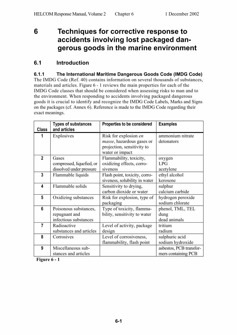
HELCOM Response Manual, Volume 2 Chapter 6 1 December 2002
6-1
6 Techniques for corrective response to accidents involving lost packaged dan-gerous goods in the marine environment
6.1 Introduction 6.1.1 The International Maritime Dangerous Goods Code (IMDG Code) The IMDG Code (Ref. 40) contains information on several thousands of substances, materials and articles. Figure 6 - 1 reviews the main properties for each of the IMDG Code classes that should be considered when assessing risks to man and to the environment. When responding to accidents involving packaged dangerous goods it is crucial to identify and recognize the IMDG Code Labels, Marks and Signs on the packages (cf. Annex 6). Reference is made to the IMDG Code regarding their exact meanings.
Class
Types of substances and articles
Properties to be considered Examples
1 Explosives Risk for explosion en masse, hazardous gases or projection, sensitivity to water or impact
ammonium nitrate detonators
2 Gases compressed, liquefied, or dissolved under pressure
Flammability, toxicity, oxidizing effects, corro-siveness
oxygen LPG acetylene
3 Flammable liquids Flash point, toxicity, corro-siveness, solubility in water
ethyl alcohol kerosene
4 Flammable solids Sensitivity to drying, carbon dioxide or water
sulphur calcium carbide
5 Oxidizing substances Risk for explosion, type of packaging
hydrogen peroxide sodium chlorate
6 Poisonous substances, repugnant and infectious substances
Type of toxicity, flamma-bility, sensitivity to water
phenol, TML, TEL dung dead animals
7 Radioactive substances and articles
Level of activity, package design
tritium radium
8 Corrosives Level of corrosiveness, flammability, flash point
sulphuric acid sodium hydroxide
9 Miscellaneous sub-stances and articles
asbestos, PCB transfor-mers containing PCB
Figure 6 - 1

HELCOM Response Manual, Volume 2 Chapter 6 1 December 2002
6-2
6.1.2 Approval of packagings for transport of dangerous goods All packagings for transport of dan-gerous goods must be type approved. This is also applies to outer packag-ings (e.g. salvage drums) for con-tainment and transport of damaged drums or similar containers. Testing and type approval of packag-ings for dangerous goods are per-formed by authorized institutes in each country and the approvals are valid internationally. Type approved packagings are al-ways marked according to a template system. For a tight head steel drum the marking is shown in Figure 6 - 2 and for a removable head steel sal-vage drum the marking is shown in Figure 6 - 5.
Figure 6 - 2 Template for a type approved steel drum.
6.2 Examples of packagings and containers 6.2.1 General A great variety of packagings are used for transportation of dangerous goods, e.g. sacks, boxes, carboys, drums, jerricans and steel cylinders. These types of small packages are usually stowed in freight containers. Portable tanks, road and rail vehicles, freight containers, large packagings (LP:s) intermediate bulk containers (IBC:s) and nuclear fuel flasks are also regarded as packagings in this context. 6.2.2.1 Small and intermediate size packagings Salvage drums The IMDG Code, 2000 Edition, 1.2.1 Definitions, states the following: "Salvage packagings means special packagings conforming to the applicable provisions of this Code into which damaged, defective or leaking dangerous goods packages, or dangerous goods that have spilled or leaked are placed, for the purpose of transport, recovery or disposal". A salvage drum is always larger than the inner package allowing the latter to be placed inside the salvage drum for safe shipment to a disposal or treatment facility. The construction material of the salvage drum must be compatible with the substance in the inner package. Salvage drums are usually made of steel or polyethylene. Salvage drums must pass, at a minimum, standard UN performance requirements and shall be marked with the appropriate UN approval (cf. Figure 6 - 5).
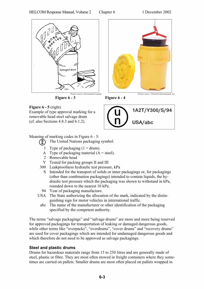
HELCOM Response Manual, Volume 2 Chapter 6 1 December 2002
6-3
Picture source: Environment Canada Picture source: UltraTech International, Inc.
Figure 6 - 3 Figure 6 - 4 Figure 6 - 5 (right) Example of type approval marking for a removable head steel salvage drum (cf. also Sections 4.8.3 and 6.1.2).
Meaning of marking codes in Figure 6 - 5:
The United Nations packaging symbol.
1 Type of packaging (1 = drum). A Type of packaging material (A = steel). 2 Removable head Y Tested for packing groups II and III
300 Leakproofness hydraulic test pressure, kPa S Intended for the transport of solids or inner packagings or, for packagings
(other than combination packagings) intended to contain liquids, the hy-draulic test pressure which the packaging was shown to withstand in kPa, rounded down to the nearest 10 kPa.
94 USA
Year of packaging manufacture. The State authorizing the allocation of the mark, indicated by the distin-guishing sign for motor vehicles in international traffic.
abc The name of the manufacturer or other identification of the packaging specified by the competent authority.
The terms “salvage packagings” and “salvage drums” are more and more being reserved for approved packagings for transportation of leaking or damaged dangerous goods, while other terms like “overpacks”, “overdrums”, “cover drums” and “recovery drums” are used for cover packagings which are intended for undamaged dangerous goods and which therefore do not need to be approved as salvage packagings. Steel and plastic drums Drums for hazardous materials range from 15 to 250 litres and are generally made of steel, plastic or fibre. They are most often stowed in freight containers where they some-times are carried on pallets. Smaller drums are most often placed on pallets wrapped in

HELCOM Response Manual, Volume 2 Chapter 6 1 December 2002
6-4
polyethylene sheets. Around 80 or 160 large drums (~ 200 litres) can be stowed in a 20-foot resp. 40-foot box container.
Common characteristics of steel drums
External volume (litres)
Tare (kg)
Volume of contents (litres)
225 15-20 200-210 120 12-15 110 60 4-6 55
The traditional steel drums are very common as containers for both chemicals and petro-leum products. Two main types are used: With tight heads (non-removable heads) for liquids and with open heads (removable heads) for solids. The heads on the latter type are fastened by locking rings. This type has often also a plastic bag as an inner packaging.
Figure 6 - 6 30 2.5-4 27
Figure 6 - 7 Tight head or non-removable head drums for liquids
Picture source: Van Leer Sweden
Figure 6 - 8 Open head or remov-able head drums for solids
Drums are most often carried in dry freight containers where a 20-foot container can take between 78 and 82 pieces of 225 litre-drums. Drums may also be stowed and strapped on loading pallets and wrapped in polyethylene sheets. An empty loading pallet weighs between 7 and 10 kg. Drums as well as many other types of packagings are now often made of plas-tics. Also plastic drums are manufactured in the two forms: With tight heads (non-removable heads) for liquids and with open heads (removable heads) for solids. Figure 6 - 9 (down)
Common characteristics of plastic drums
External volume (litres)
Tare (kg)
Volume of contents (litres)
No. of drums
per pallet 215-225 8-10.5 200 4 125-130 3.5-4.5 120 5 65-68 2-3.5 60 8 32-33 1-1.6 30 12
Picture source: Hazardous Cargo Bulletin
Figure 6 - 10 Drums and other types of plastic packagings for dangerous goods
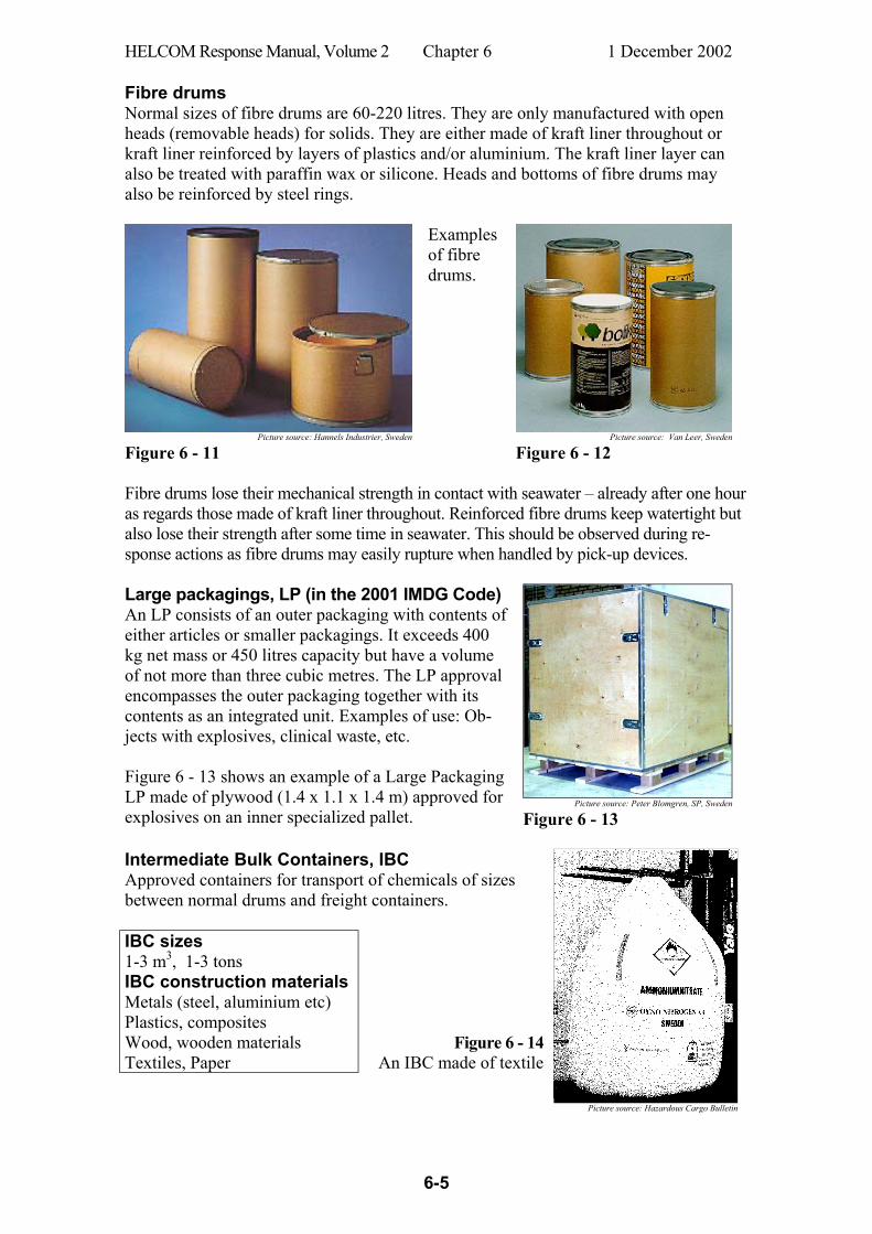
HELCOM Response Manual, Volume 2 Chapter 6 1 December 2002
6-5
Fibre drums Normal sizes of fibre drums are 60-220 litres. They are only manufactured with open heads (removable heads) for solids. They are either made of kraft liner throughout or kraft liner reinforced by layers of plastics and/or aluminium. The kraft liner layer can also be treated with paraffin wax or silicone. Heads and bottoms of fibre drums may also be reinforced by steel rings.
Examples of fibre drums.
Picture source: Hannels Industrier, Sweden Picture source: Van Leer, Sweden
Figure 6 - 11 Figure 6 - 12 Fibre drums lose their mechanical strength in contact with seawater – already after one hour as regards those made of kraft liner throughout. Reinforced fibre drums keep watertight but also lose their strength after some time in seawater. This should be observed during re-sponse actions as fibre drums may easily rupture when handled by pick-up devices.
Picture source: Peter Blomgren, SP, Sweden
Large packagings, LP (in the 2001 IMDG Code) An LP consists of an outer packaging with contents of either articles or smaller packagings. It exceeds 400 kg net mass or 450 litres capacity but have a volume of not more than three cubic metres. The LP approval encompasses the outer packaging together with its contents as an integrated unit. Examples of use: Ob-jects with explosives, clinical waste, etc. Figure 6 - 13 shows an example of a Large Packaging LP made of plywood (1.4 x 1.1 x 1.4 m) approved for explosives on an inner specialized pallet. Figure 6 - 13 Intermediate Bulk Containers, IBC Approved containers for transport of chemicals of sizes between normal drums and freight containers. IBC sizes 1-3 m3, 1-3 tons IBC construction materials Metals (steel, aluminium etc) Plastics, composites Wood, wooden materials Textiles, Paper
Figure 6 - 14 An IBC made of textile
Picture source: Hazardous Cargo Bulletin

HELCOM Response Manual, Volume 2 Chapter 6 1 December 2002
6-6
Picture source: Van Leer, Sweden Picture source: Bison Containers, Norway
Figure 6 - 15 An IBC made of plastic
Figure 6 - 16 An IBC made of metal
6.2.3 Sea freight containers Standard dry freight containers and tank containers are often used for transport of chemicals and dangerous goods at land, at sea and on inland waterways. They are interna-tionally standard-ised. Standard dry freight containers and are normally 20 feet or 40 feet in length and tank containers are 20 feet. Figure 6 - 17 from a tank con-tainer manufacturer illustrates that a tank container can hold more liquid than a dry freight container of the same size stowed with drums.
Picture source: Sea Containers Services Ltd.
Figure 6 - 17 A tank container can take 43 % more liquid than a dry freight container of the same external dimension.
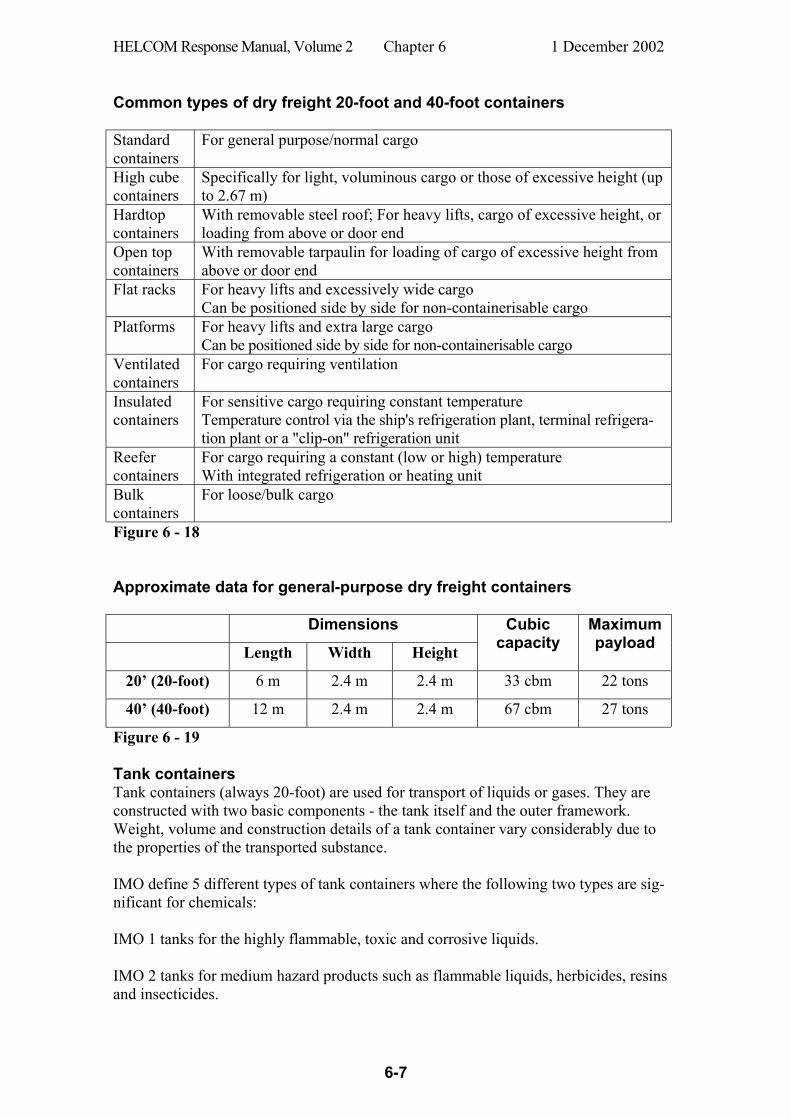
HELCOM Response Manual, Volume 2 Chapter 6 1 December 2002
6-7
Common types of dry freight 20-foot and 40-foot containers Standard containers
For general purpose/normal cargo
High cube containers
Specifically for light, voluminous cargo or those of excessive height (up to 2.67 m)
Hardtop containers
With removable steel roof; For heavy lifts, cargo of excessive height, or loading from above or door end
Open top containers
With removable tarpaulin for loading of cargo of excessive height from above or door end
Flat racks For heavy lifts and excessively wide cargo Can be positioned side by side for non-containerisable cargo
Platforms For heavy lifts and extra large cargo Can be positioned side by side for non-containerisable cargo
Ventilated containers
For cargo requiring ventilation
Insulated containers
For sensitive cargo requiring constant temperature Temperature control via the ship's refrigeration plant, terminal refrigera-tion plant or a "clip-on" refrigeration unit
Reefer containers
For cargo requiring a constant (low or high) temperature With integrated refrigeration or heating unit
Bulk containers
For loose/bulk cargo
Figure 6 - 18 Approximate data for general-purpose dry freight containers
Dimensions Length Width Height
Cubic capacity
Maximum payload
20’ (20-foot) 6 m 2.4 m 2.4 m 33 cbm 22 tons
40’ (40-foot) 12 m 2.4 m 2.4 m 67 cbm 27 tons
Figure 6 - 19 Tank containers Tank containers (always 20-foot) are used for transport of liquids or gases. They are constructed with two basic components - the tank itself and the outer framework. Weight, volume and construction details of a tank container vary considerably due to the properties of the transported substance. IMO define 5 different types of tank containers where the following two types are sig-nificant for chemicals: IMO 1 tanks for the highly flammable, toxic and corrosive liquids. IMO 2 tanks for medium hazard products such as flammable liquids, herbicides, resins and insecticides.

HELCOM Response Manual, Volume 2 Chapter 6 1 December 2002
6-8
6.3 Labelling and marking of dangerous goods The IMDG (International Maritime Dangerous Goods) Code (Ref. 40) contains provi-sions on how packaged dangerous goods should be labelled. These provisions are valid for all types of transported packages that might be inspected on any occasion in order to determine their contents. The IMDG Code contains all details on how dangerous goods must be labelled. The labels are shown in Annex 6. If the substance in the package besides the main hazard (e.g. toxic) also exhibits an extra so called “subsidiary risk” (e.g. corrosive) this must also be shown by extra labels (see Figure 6 - 26). The contents of the package must be given on the exterior of the packaging by sub-stance’s proper shipping name (correct technical name). The proper shipping name is the name of the substance under which it is listed in the IMDG Code. The proper ship-ping name must also be supplemented by a chemical name of the substance and by the UN number (cf. Figure 6 - 22 and Figure 6 - 27). The substance’s name may be given in the national language for domestic transport, but most countries require English for international transport. The packaging must be approved for transport of dangerous goods (cf. Section 6.1.2), and this approval must be marked on the packaging (cf. the drum’s head in Figure 6 - 22). Labels and inscriptions must be clearly readable after three months in seawater. The labels’ sizes should be 100 mm x 100 mm for smaller packages (drums, boxes, etc.) and 250 mm x 250 mm for freight containers and dangerous goods on pallets. The US National Fire Protection Association (NFPA) has a marking system ("the NFPA fire diamond", Figure 6 - 20) that indicates the dangers associated with various hazardous materi-als (cf. Annex 6). The system is intended for use on fixed instal-lations, like storage containers, storage rooms and warehouses, entrances to laboratories, and chemical processing equipment. The system is designed for the benefit of emergency responders. Though the system is not required in transportation it is often seen on transported dangerous goods all over the world. (See Annex 6)
Figure 6 - 20
Tank cars and tank containers running by road under interna-tional ADR regulations will carry a two- or three-digit code, referred to as the Hazard Identification Number (HIN) or the Kemler Code. This code gives information about the hazards involved in dealing with the material. If the digits are preceded by an X (as in Figure 6 - 21) it indicates that the substance reacts dangerously with water. The number below the Kemler Code is the UN number for the substance. (See Annex 6)
Figure 6 - 21
The so called Hazchem Codes are used in the UK only. They are shown on vehicles carrying dangerous by road in UK national journeys and are therefore not dealt with here.
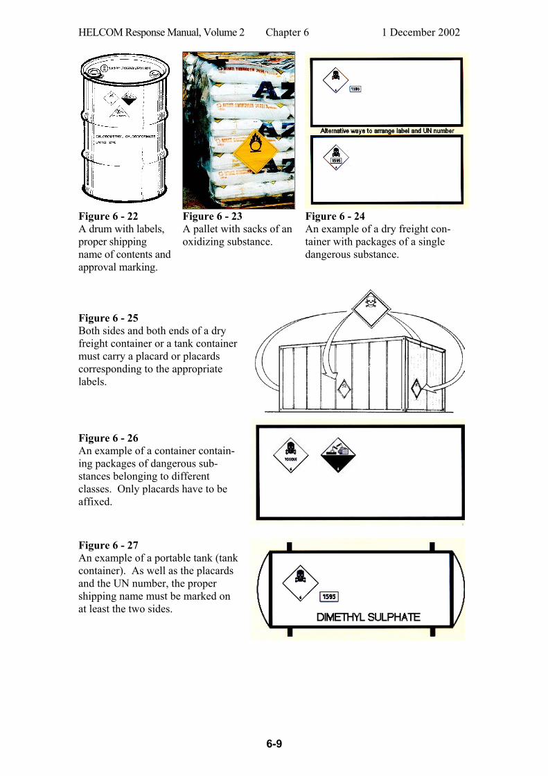
HELCOM Response Manual, Volume 2 Chapter 6 1 December 2002
6-9
Figure 6 - 22 A drum with labels, proper shipping name of contents and approval marking.
Figure 6 - 23 A pallet with sacks of an oxidizing substance.
Figure 6 - 24 An example of a dry freight con-tainer with packages of a single dangerous substance.
Figure 6 - 25 Both sides and both ends of a dry freight container or a tank container must carry a placard or placards corresponding to the appropriate labels.
Figure 6 - 26 An example of a container contain-ing packages of dangerous sub-stances belonging to different classes. Only placards have to be affixed.
Figure 6 - 27 An example of a portable tank (tank container). As well as the placards and the UN number, the proper shipping name must be marked on at least the two sides.
HELCOM Response Manual, Volume 2 Chapter 6 1 December 2002
6-10
6.4 Behaviour of packages in seawater 6.4.1 General Many properties of the packagings influence their short-term and long-term behaviour when lost at sea. Such properties are for instance: • Gross weight, gross volume, buoyancy.
• The packaging's appearance and shape (dry freight container, tank container, in-
termediate bulk container (IBC), large packaging (LP), drum, box, steel cylinder, can, bottle, sack, etc.).
• Combination of outer and inner packaging, e.g. - smaller packagings packed or stowed in dry freight containers - smaller packagings enveloped in outer safety covers - many small packaging held together by outer wrappings
• Packaging material (iron, stainless steel, aluminium, wood, plastics, composite, glass, textile, paper, etc.).
6.4.2 Grouping of packages according to their buoyancy in water It is difficult to develop a sophisticated classification system for packages of dangerous goods based on their buoyancy in water. There are actually only the two alternatives float or sink on the assumption that the package is not punctured. On rare occasions the package’s bulk density might be very close to that of the surrounding water. Then the package may float just below the water surface (is waterlogged) or may slowly sink to the bottom. In turbulent water the package may of course whirl round in the water body and neither reach the surface nor the bottom. In the so called European Classification System (Annex 4) emphasis is laid on 12 Prop-erty Groups (G, GD, E, ED, etc.) for substances. But also three Groups for packages (PF, PI and PS) are included in a flow chart which defines the Classification System (see Figure a4-1 in Annex 4). The latter three groups are also defined in Figure 6 - 28.
PF PI PS Package Floater Package Immersed Package Sinker
The package floats
The package has the same bulk density as water and is waterlogged*
The package sinks
w/v < ds - 0,01 w/v = ds ± 0,01 w/v > ds +0,01 w = the package’s gross weight, grams v = the package’s gross volume, millilitres ds = waters density, grams/millilitre Figure 6 - 28 (cf. Annex 4)
*A waterlogged package may, due to the intensity of water currents, tumble around in the water column at varying depth.
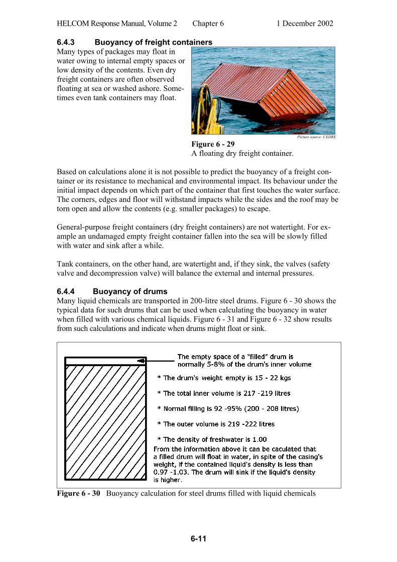
HELCOM Response Manual, Volume 2 Chapter 6 1 December 2002
6-11
6.4.3 Buoyancy of freight containers Many types of packages may float in water owing to internal empty spaces or low density of the contents. Even dry freight containers are often observed floating at sea or washed ashore. Some-times even tank containers may float.
Picture source: CEDRE
Figure 6 - 29 A floating dry freight container.
Based on calculations alone it is not possible to predict the buoyancy of a freight con-tainer or its resistance to mechanical and environmental impact. Its behaviour under the initial impact depends on which part of the container that first touches the water surface. The corners, edges and floor will withstand impacts while the sides and the roof may be torn open and allow the contents (e.g. smaller packages) to escape. General-purpose freight containers (dry freight containers) are not watertight. For ex-ample an undamaged empty freight container fallen into the sea will be slowly filled with water and sink after a while. Tank containers, on the other hand, are watertight and, if they sink, the valves (safety valve and decompression valve) will balance the external and internal pressures. 6.4.4 Buoyancy of drums Many liquid chemicals are transported in 200-litre steel drums. Figure 6 - 30 shows the typical data for such drums that can be used when calculating the buoyancy in water when filled with various chemical liquids. Figure 6 - 31 and Figure 6 - 32 show results from such calculations and indicate when drums might float or sink.
Figure 6 - 30 Buoyancy calculation for steel drums filled with liquid chemicals
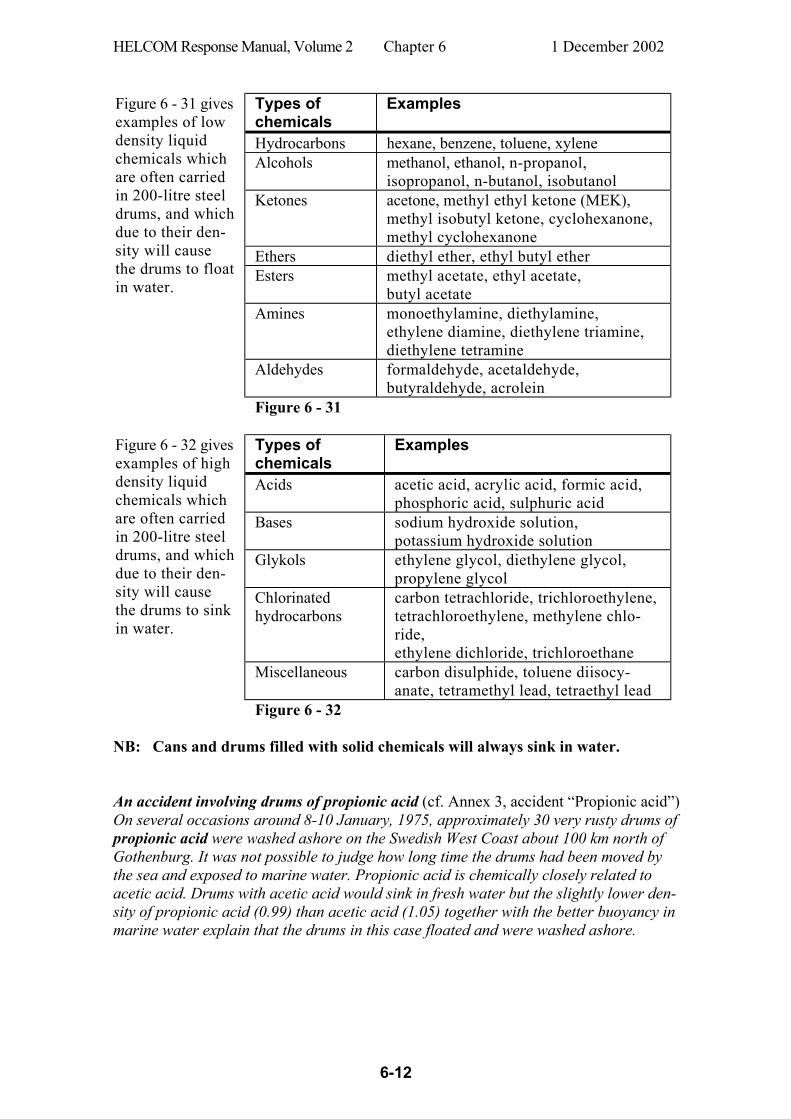
HELCOM Response Manual, Volume 2 Chapter 6 1 December 2002
6-12
Types of chemicals
Examples
Hydrocarbons hexane, benzene, toluene, xylene Alcohols methanol, ethanol, n-propanol,
isopropanol, n-butanol, isobutanol Ketones acetone, methyl ethyl ketone (MEK),
methyl isobutyl ketone, cyclohexanone, methyl cyclohexanone
Ethers diethyl ether, ethyl butyl ether Esters methyl acetate, ethyl acetate,
butyl acetate Amines monoethylamine, diethylamine,
ethylene diamine, diethylene triamine, diethylene tetramine
Aldehydes formaldehyde, acetaldehyde, butyraldehyde, acrolein
Figure 6 - 31 gives examples of low density liquid chemicals which are often carried in 200-litre steel drums, and which due to their den-sity will cause the drums to float in water.
Figure 6 - 31
Types of chemicals
Examples
Acids acetic acid, acrylic acid, formic acid, phosphoric acid, sulphuric acid
Bases sodium hydroxide solution, potassium hydroxide solution
Glykols ethylene glycol, diethylene glycol, propylene glycol
Chlorinated hydrocarbons
carbon tetrachloride, trichloroethylene, tetrachloroethylene, methylene chlo-ride, ethylene dichloride, trichloroethane
Miscellaneous carbon disulphide, toluene diisocy-anate, tetramethyl lead, tetraethyl lead
Figure 6 - 32 gives examples of high density liquid chemicals which are often carried in 200-litre steel drums, and which due to their den-sity will cause the drums to sink in water.
Figure 6 - 32 NB: Cans and drums filled with solid chemicals will always sink in water. An accident involving drums of propionic acid (cf. Annex 3, accident “Propionic acid”) On several occasions around 8-10 January, 1975, approximately 30 very rusty drums of propionic acid were washed ashore on the Swedish West Coast about 100 km north of Gothenburg. It was not possible to judge how long time the drums had been moved by the sea and exposed to marine water. Propionic acid is chemically closely related to acetic acid. Drums with acetic acid would sink in fresh water but the slightly lower den-sity of propionic acid (0.99) than acetic acid (1.05) together with the better buoyancy in marine water explain that the drums in this case floated and were washed ashore.
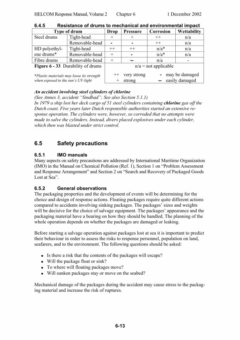
HELCOM Response Manual, Volume 2 Chapter 6 1 December 2002
6-13
6.4.5 Resistance of drums to mechanical and environmental impact Type of drum Drop Pressure Corrosion Wettability
Tight-head + + ++ n/a Steel drums Removable-head - - ++ n/a Tight-head ++ ++ n/a* n/a HD polyethyl-
ene drums* Removable-head + - n/a* n/a Fibre drums Removable-head + -- n/a - Figure 6 - 33 Durability of drums n/a = not applicable
++ very strong - may be damaged *Plastic materials may loose its strength when exposed to the sun’s UV-light + strong -- easily damaged An accident involving steel cylinders of chlorine (See Annex 3, accident “Sindbad”; See also Section 5.1.1) In 1979 a ship lost her deck cargo of 51 steel cylinders containing chlorine gas off the Dutch coast. Five years later Dutch responsible authorities started an extensive re-sponse operation. The cylinders were, however, so corroded that no attempts were made to salve the cylinders. Instead, divers placed explosives under each cylinder, which then was blasted under strict control. 6.5 Safety precautions 6.5.1 IMO manuals Many aspects on safety precautions are addressed by International Maritime Organization (IMO) in the Manual on Chemical Pollution (Ref. 1), Section 1 on “Problem Assessment and Response Arrangement” and Section 2 on “Search and Recovery of Packaged Goods Lost at Sea”. 6.5.2 General observations The packaging properties and the development of events will be determining for the choice and design of response actions. Floating packages require quite different actions compared to accidents involving sinking packages. The packages’ sizes and weights will be decisive for the choice of salvage equipment. The packages’ appearance and the packaging material have a bearing on how they should be handled. The planning of the whole operation depends on whether the packages are damaged or leaking. Before starting a salvage operation against packages lost at sea it is important to predict their behaviour in order to assess the risks to response personnel, population on land, seafarers, and to the environment. The following questions should be asked: • Is there a risk that the contents of the packages will escape? • Will the package float or sink? • To where will floating packages move? • Will sunken packages stay or move on the seabed? Mechanical damage of the packages during the accident may cause stress to the packag-ing material and increase the risk of ruptures.
HELCOM Response Manual, Volume 2 Chapter 6 1 December 2002
6-14
6.5.3 General checklist Always observe the greatest caution when starting to inspect and salvage a
package which is suspected to contain chemicals. A package with unknown contents and with no interpretable information on its cover must be considered dangerous until clarity is achieved. Always act on a worst possible case basis.
All relevant information should first be gathered about the chemicals as well as the properties of the packaging.
Adjust the level of the personnel protection to the contents of the package (if known) as well as package size and appearance (damage, leakage)
Observe the uttermost caution if the contents and the appearance of the package are unknown.
Unprotected personnel must be directed to the windward side of packages with unknown contents or packages with hazardous leakage.
Use appropriate personnel safety equipment if there is any risk for the packag-ings to be damaged during the salvage.
Observe the greatest caution when working close to crane lift operations, espe-cially when loaded freight containers are involved.
With due consideration to safety, mark as soon as possible large containers with appropriate devices (buoys and/or radio/radar beacons, reflectors or transmit-ters). Se also Section 6.7.4.
Take samples of the contents of damaged (and leaking) packages. Sampling of intact packages should be avoided.
The packaging material’s weather resistance will significantly influence the safety precautions during the response action. E.g. paper and wood fibre exhibit short marine environmental durability while casings of e.g. iron may resist several years before they are penetrated by rust (Ref. 41, Ref. 42 and Ref. 43). Recovered packages containing chemicals and dangerous goods should always be treated with greatest caution during the salvage action as damaged packagings might leak. Smaller packages that are adversely affected by the marine environment should by safety reasons always be transferred into salvage drums (cf. Figure 6 - 3) before other actions and transport. Note that these salvage drums must be approved for transport of dangerous goods.
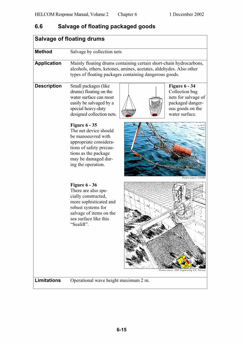
HELCOM Response Manual, Volume 2 Chapter 6 1 December 2002
6-15
6.6 Salvage of floating packaged goods Salvage of floating drums Method Salvage by collection nets
Application Mainly floating drums containing certain short-chain hydrocarbons,
alcohols, ethers, ketones, amines, acetates, aldehydes. Also other types of floating packages containing dangerous goods.
Description
Small packages (like drums) floating on the water surface can most easily be salvaged by a special heavy-duty designed collection nets.
Figure 6 - 34 Collection bag nets for salvage of packaged danger-ous goods on the water surface.
Figure 6 - 35 The net device should be manoeuvred with appropriate considera-tions of safety precau-tions as the package may be damaged dur-ing the operation.
Picture source: CEDRE
Figure 6 - 36 There are also spe-cially constructed, more sophisticated and robust systems for salvage of items on the sea surface like this “Sealift”.
Picture source: SMV Engineering A.S., Norway
Limitations Operational wave height maximum 2 m.
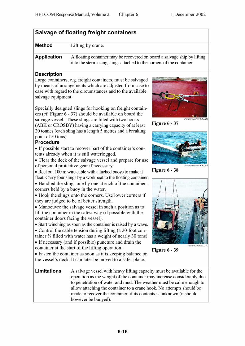
HELCOM Response Manual, Volume 2 Chapter 6 1 December 2002
6-16
Salvage of floating freight containers Method Lifting by crane.
Application A floating container may be recovered on board a salvage ship by lifting
it to the stern using slings attached to the corners of the container.
Description Large containers, e.g. freight containers, must be salvaged by means of arrangements which are adjusted from case to case with regard to the circumstances and to the available salvage equipment. Specially designed slings for hooking on freight contain-ers (cf. Figure 6 - 37) should be available on board the salvage vessel. These slings are fitted with two hooks (ABK or CROSBY) having a carrying capacity of at least 20 tonnes (each sling has a length 5 metres and a breaking point of 50 tons). Procedure • If possible start to recover part of the container’s con-tents already when it is still waterlogged. • Clear the deck of the salvage vessel and prepare for use of personal protective gear if necessary. • Reel out 100 m wire cable with attached buoys to make it float. Carry four slings by a workboat to the floating container. • Handled the slings one by one at each of the container-corners held by a buoy in the water. • Hook the slings onto the corners. Use lower corners if they are judged to be of better strength. • Manoeuvre the salvage vessel in such a position as to lift the container in the safest way (if possible with the container doors facing the vessel). • Start winching as soon as the container is raised by a wave. • Control the cable tension during lifting (a 20-foot con-tainer ¾ filled with water has a weight of nearly 30 tons). • If necessary (and if possible) puncture and drain the container at the start of the lifting operation. • Fasten the container as soon as it is keeping balance on the vessel’s deck. It can later be moved to a safer place.
Picture source: CEDRE
Figure 6 - 37
Picture source: CEDRE
Figure 6 - 38
Picture source: IMO
Figure 6 - 39
Limitations A salvage vessel with heavy lifting capacity must be available for the operation as the weight of the container may increase considerably due to penetration of water and mud. The weather must be calm enough to allow attaching the container to a crane hook. No attempts should be made to recover the container if its contents is unknown (it should however be buoyed).
HELCOM Response Manual, Volume 2 Chapter 6 1 December 2002
6-17
Salvage of floating freight containers Method Towing to a safe haven.
Application A towline is attached to one or more of the container corners and the
container is towed to a haven where it can be safely taken care of.
Description Experience has shown that a floating freight container during a towing operation (cf. Annex 3, accident Perintis) may be acciden-tally lost and unable to be found again. It is therefore important prior to the towage operation to equip the container with
1) a large buoyant device (floatation boom or collar) with buoy-ancy enough to keep the container afloat, and
2) a tracing device e.g. radio transmitter, transponder, radar reflec-tor or optical blinker.
It is recommended that four propylene ropes are attached asymmet-rically to the corners of one of the short sides of the container. Two by two of the ropes should be of equal length. The length of two of the ropes should be double or threefold the length of the shorter ones. The ropes of equal lengths should be attached in the corners of the same perpendicular. In such a way one of the edges of the short side of the container will plough through the water like the stem of a ship. The resistance of the water during such a towage is considerably reduced compared to if the ropes would be attached in a symmetric way to the container. The ropes could be difficult to attach even in a slight sea swell and sometimes it might be judged to be enough with two hooks (one submerged) at each end of a vertical edge. If the sea is too rough for a fastening the hook on a submerged corner it might be sufficient to attach a single rope to one of the available hooks above the water surface.
Limitations Towage of a container with potentially hazardous leaking content must be planned carefully in order to avoid vulnerable coastal sites. The safe haven for the container as well as all safety precautions must be carefully selected and planned with appropriate regard to the operation against the container.
HELCOM Response Manual, Volume 2 Chapter 6 1 December 2002
6-18
6.7 Salvage operations involving sunken packaged goods 6.7.1 General Specialist resources must often be used in connection with activities described below. Searches, especially over large sea bottom areas, are best done by using side
scan sonar.
Selection of echoes is performed by interpretation of imageries from a sides can sonar.
Locating and positioning of echoes can be done by a system consisting of a hydroacoustic transmitter on board a search vessel and transponders which are set out on the bottom within the search area.
Sorting out insignificant echoes can to some extent be made by colour coded sector scanning sonars.
Identification of remaining ”hot” echoes could preferably be done by sub-mersibles to ascertain which of the echoes originate from intended items.
Close inspection of found items should be done by submersibles or divers in order to find out their physical appearance, i.e. if they are leaking, how they should be salvaged, etc.
Salvage of goods on the seabed. 6.7.2 Locating packages on the seabed When lost packages have sunk to the seabed it will normally be necessary to search for them over a large area. When targets are spotted, they should be inspected more closely, in order either to discard them as false, or to identify them as the lost pack-ages. The work to find packages on the seabed may comprise the following phases, which all also include special routines for precision navigation:
- Large bottom area search - Checks on obtained echoes - Inspection of found goods - Salvage of goods
Locating packages on the seabed may be very difficult and will depend on the situa-tion. When organizing and performing a search for lost packages, the most impor-tant information is the position report and an indication of its accuracy. The water depth and the topography of the sea floor will highly influence the complexity of the search operation. Other important factors affecting the search are package type, size and shape, packing material, as well as sea currents and sea state. Currents may also move packages from the known position or cover them with bottom sediments. Their position may also be affected by fishermen’s trawling. Precision navigation systems On many occasions during search operations at sea, it is necessary to utilize spe-cific navigational systems to be able to manoeuvre vessels in a precise manner and make accurate map plots of the search area.
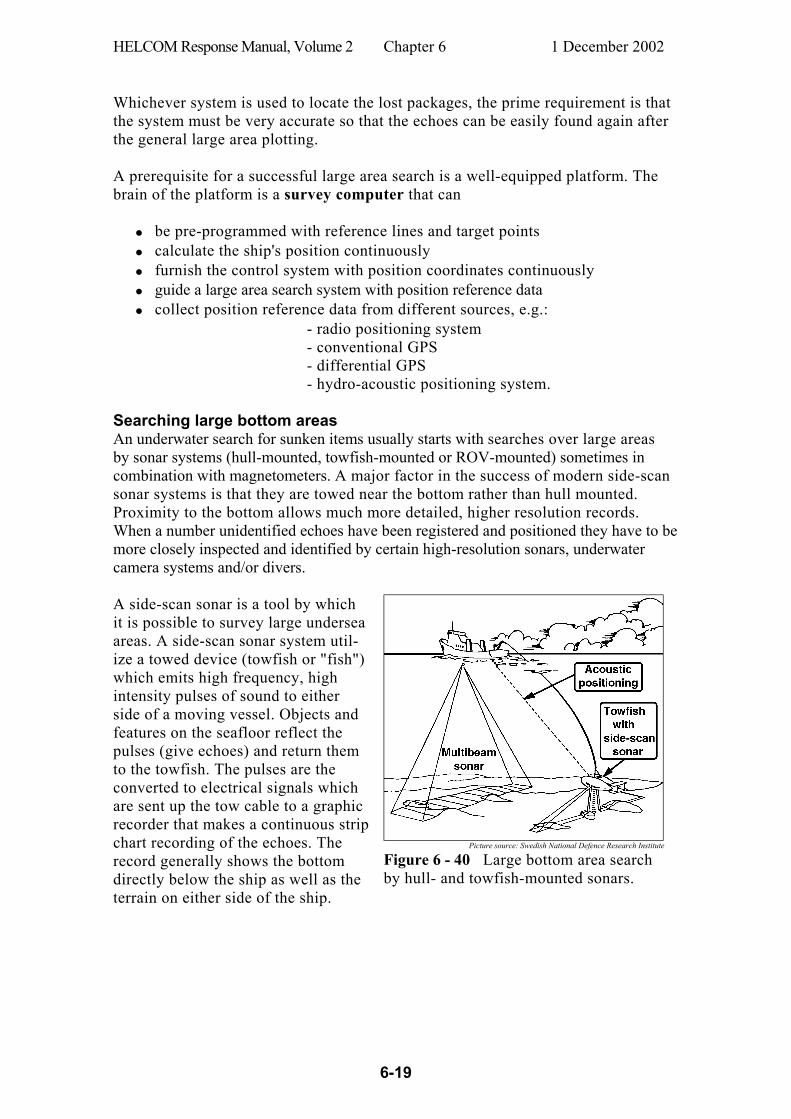
HELCOM Response Manual, Volume 2 Chapter 6 1 December 2002
6-19
Whichever system is used to locate the lost packages, the prime requirement is that the system must be very accurate so that the echoes can be easily found again after the general large area plotting. A prerequisite for a successful large area search is a well-equipped platform. The brain of the platform is a survey computer that can • be pre-programmed with reference lines and target points • calculate the ship's position continuously • furnish the control system with position coordinates continuously • guide a large area search system with position reference data • collect position reference data from different sources, e.g.: - radio positioning system
- conventional GPS - differential GPS - hydro-acoustic positioning system.
Searching large bottom areas An underwater search for sunken items usually starts with searches over large areas by sonar systems (hull-mounted, towfish-mounted or ROV-mounted) sometimes in combination with magnetometers. A major factor in the success of modern side-scan sonar systems is that they are towed near the bottom rather than hull mounted. Proximity to the bottom allows much more detailed, higher resolution records. When a number unidentified echoes have been registered and positioned they have to be more closely inspected and identified by certain high-resolution sonars, underwater camera systems and/or divers. A side-scan sonar is a tool by which it is possible to survey large undersea areas. A side-scan sonar system util-ize a towed device (towfish or "fish") which emits high frequency, high intensity pulses of sound to either side of a moving vessel. Objects and features on the seafloor reflect the pulses (give echoes) and return them to the towfish. The pulses are the converted to electrical signals which are sent up the tow cable to a graphic recorder that makes a continuous strip chart recording of the echoes. The record generally shows the bottom directly below the ship as well as the terrain on either side of the ship.
Picture source: Swedish National Defence Research Institute
Figure 6 - 40 Large bottom area search by hull- and towfish-mounted sonars.
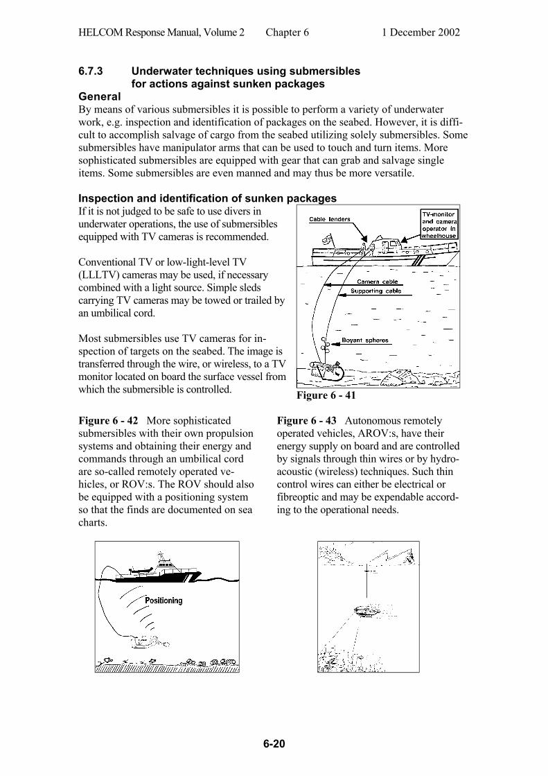
HELCOM Response Manual, Volume 2 Chapter 6 1 December 2002
6-20
6.7.3 Underwater techniques using submersibles
for actions against sunken packages General By means of various submersibles it is possible to perform a variety of underwater work, e.g. inspection and identification of packages on the seabed. However, it is diffi-cult to accomplish salvage of cargo from the seabed utilizing solely submersibles. Some submersibles have manipulator arms that can be used to touch and turn items. More sophisticated submersibles are equipped with gear that can grab and salvage single items. Some submersibles are even manned and may thus be more versatile. Inspection and identification of sunken packages If it is not judged to be safe to use divers in underwater operations, the use of submersibles equipped with TV cameras is recommended. Conventional TV or low-light-level TV (LLLTV) cameras may be used, if necessary combined with a light source. Simple sleds carrying TV cameras may be towed or trailed by an umbilical cord. Most submersibles use TV cameras for in-spection of targets on the seabed. The image is transferred through the wire, or wireless, to a TV monitor located on board the surface vessel from which the submersible is controlled.
Figure 6 - 41 Figure 6 - 42 More sophisticated submersibles with their own propulsion systems and obtaining their energy and commands through an umbilical cord are so-called remotely operated ve-hicles, or ROV:s. The ROV should also be equipped with a positioning system so that the finds are documented on sea charts.
Figure 6 - 43 Autonomous remotely operated vehicles, AROV:s, have their energy supply on board and are controlled by signals through thin wires or by hydro-acoustic (wireless) techniques. Such thin control wires can either be electrical or fibreoptic and may be expendable accord-ing to the operational needs.
HELCOM Response Manual, Volume 2 Chapter 6 1 December 2002
6-21
If the identity of the contents is known (e.g. if the labelling is intact), the hazards can readily be assessed. If not, identification of the contents and assessment of the hazards should be obtained before recovery is attempted. If the presence of radioactive material is suspected, measurement of the radiation level should be carried out before any other actions. It may be possible to use detection equipment (monitoring instruments) in the field to assist in these processes. A chemical laboratory may be necessary to identify samples where the use of detection equipment is insufficient. 6.7.4 Providing sunken gods with pingers and buoyant bags Pingers When sunken items have been found and identified it is necessary to mark them in order to facilitate for response personnel to find them afterwards. Acoustic transmitters (ping-ers”) can be used. They send ultrasonic pulses of certain frequencies which easily propagate long distances in water. With receiving (homing) systems the source can afterwards be located. The choice of frequency is of vital importance as low frequency (10 kHz) sound is transmitted longer but more difficult to locate exactly than a high frequency (40 kHz) sound. Acoustic transmitters are normally very reliable but they should not be attached directly to the item on the seabed as masking effects may restrain the sound transmission in certain directions. The pinger should instead be attached firmly to the item by means of a 20 m long floating rope. Such a buoyant pinger reduces the risk of masking. Buoyant bags In some cases it may be beneficial to raise the item found on the seabed to the surface by attaching buoyant bags to it. 6.7.5 Underwater techniques using divers
for actions against sunken packages General Response actions against sunken packages can be ac-complished by trained divers or by other means. The prime three diving techniques are the following:
- SCUBA diving - Saturation diving - Atmospheric diving
Divers working with leaking packages should take particular care as the diver's suit may be torn and his skin may be exposed to the leaking substance. Therefore the divers should wear protective gear appropriate to the hazard involved to avoid skin contact with the surrounding water. The best solution is normally acquired by dry diving suits which are certified for the specific chemicals involved. Packages up to the size of drums may be transferred by means of a transfer crane to a large container which is lifted to the surface when filled. Larger packages may be at-tached one by one to a line and lifted to the surface. These methods can be used for packages on the seabed or in a sunken ship. In the latter case the ships hull may need to be opened in order to reach the packages inside the ship, possibly causing the packages to float free.
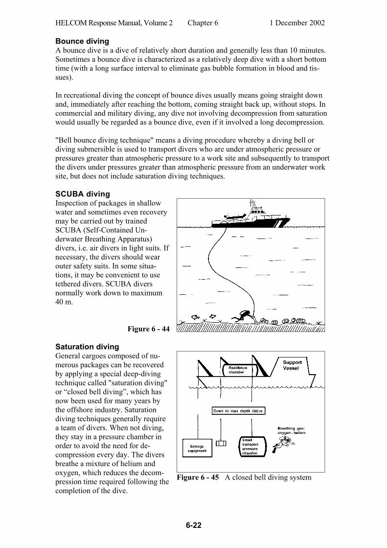
HELCOM Response Manual, Volume 2 Chapter 6 1 December 2002
6-22
Bounce diving A bounce dive is a dive of relatively short duration and generally less than 10 minutes. Sometimes a bounce dive is characterized as a relatively deep dive with a short bottom time (with a long surface interval to eliminate gas bubble formation in blood and tis-sues). In recreational diving the concept of bounce dives usually means going straight down and, immediately after reaching the bottom, coming straight back up, without stops. In commercial and military diving, any dive not involving decompression from saturation would usually be regarded as a bounce dive, even if it involved a long decompression. "Bell bounce diving technique" means a diving procedure whereby a diving bell or diving submersible is used to transport divers who are under atmospheric pressure or pressures greater than atmospheric pressure to a work site and subsequently to transport the divers under pressures greater than atmospheric pressure from an underwater work site, but does not include saturation diving techniques. SCUBA diving Inspection of packages in shallow water and sometimes even recovery may be carried out by trained SCUBA (Self-Contained Un-derwater Breathing Apparatus) divers, i.e. air divers in light suits. If necessary, the divers should wear outer safety suits. In some situa-tions, it may be convenient to use tethered divers. SCUBA divers normally work down to maximum 40 m.
Figure 6 - 44 Saturation diving General cargoes composed of nu-merous packages can be recovered by applying a special deep-diving technique called "saturation diving" or “closed bell diving”, which has now been used for many years by the offshore industry. Saturation diving techniques generally require a team of divers. When not diving, they stay in a pressure chamber in order to avoid the need for de-compression every day. The divers breathe a mixture of helium and oxygen, which reduces the decom-pression time required following the completion of the dive.
Figure 6 - 45 A closed bell diving system
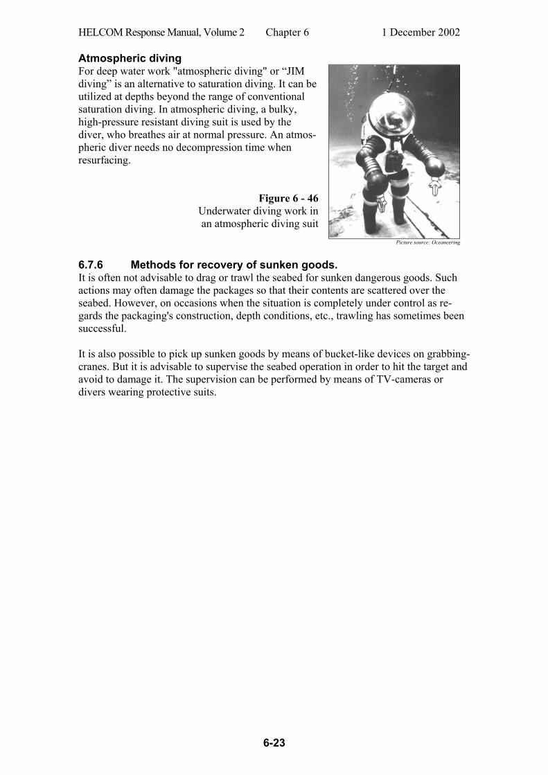
HELCOM Response Manual, Volume 2 Chapter 6 1 December 2002
6-23
Atmospheric diving For deep water work "atmospheric diving" or “JIM diving” is an alternative to saturation diving. It can be utilized at depths beyond the range of conventional saturation diving. In atmospheric diving, a bulky, high-pressure resistant diving suit is used by the diver, who breathes air at normal pressure. An atmos-pheric diver needs no decompression time when resurfacing.
Figure 6 - 46 Underwater diving work in an atmospheric diving suit
Picture source: Oceaneering
6.7.6 Methods for recovery of sunken goods. It is often not advisable to drag or trawl the seabed for sunken dangerous goods. Such actions may often damage the packages so that their contents are scattered over the seabed. However, on occasions when the situation is completely under control as re-gards the packaging's construction, depth conditions, etc., trawling has sometimes been successful. It is also possible to pick up sunken goods by means of bucket-like devices on grabbing-cranes. But it is advisable to supervise the seabed operation in order to hit the target and avoid to damage it. The supervision can be performed by means of TV-cameras or divers wearing protective suits.
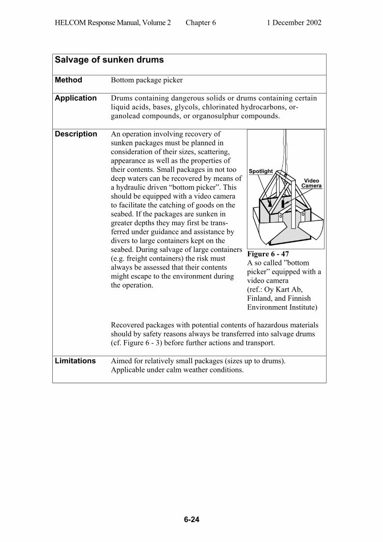
HELCOM Response Manual, Volume 2 Chapter 6 1 December 2002
6-24
Salvage of sunken drums Method Bottom package picker
Application Drums containing dangerous solids or drums containing certain
liquid acids, bases, glycols, chlorinated hydrocarbons, or-ganolead compounds, or organosulphur compounds.
Description
An operation involving recovery of sunken packages must be planned in consideration of their sizes, scattering, appearance as well as the properties of their contents. Small packages in not too deep waters can be recovered by means of a hydraulic driven “bottom picker”. This should be equipped with a video camera to facilitate the catching of goods on the seabed. If the packages are sunken in greater depths they may first be trans-ferred under guidance and assistance by divers to large containers kept on the seabed. During salvage of large containers (e.g. freight containers) the risk must always be assessed that their contents might escape to the environment during the operation.
Figure 6 - 47 A so called ”bottom picker” equipped with a video camera (ref.: Oy Kart Ab, Finland, and Finnish Environment Institute)
Recovered packages with potential contents of hazardous materials should by safety reasons always be transferred into salvage drums (cf. Figure 6 - 3) before further actions and transport.
Limitations Aimed for relatively small packages (sizes up to drums). Applicable under calm weather conditions.
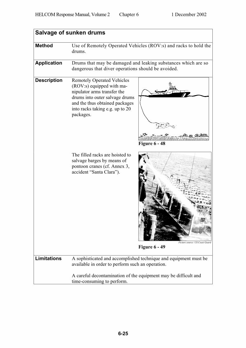
HELCOM Response Manual, Volume 2 Chapter 6 1 December 2002
6-25
Salvage of sunken drums Method Use of Remotely Operated Vehicles (ROV:s) and racks to hold the
drums.
Application Drums that may be damaged and leaking substances which are so dangerous that diver operations should be avoided.
Description
Remotely Operated Vehicles (ROV:s) equipped with ma-nipulator arms transfer the drums into outer salvage drums and the thus obtained packages into racks taking e.g. up to 20 packages.
Figure 6 - 48
The filled racks are hoisted to salvage barges by means of pontoon cranes (cf. Annex 3, accident “Santa Clara”).
Picture source: US Coast Guard
Figure 6 - 49
Limitations A sophisticated and accomplished technique and equipment must be available in order to perform such an operation. A careful decontamination of the equipment may be difficult and time-consuming to perform.

HELCOM Response Manual, Volume 2 Chapter 6 1 December 2002
6-26
Salvage of packages from depths down to 500-600 m Method Bell diving system with saturation divers
Application A demolished vessel on the sea-
bed cannot be salvaged together with its cargo by pontoon cranes. On such an occasion the opera-tion must be planned in consid-eration of the cargo’s distribution within and outside the wreck. Divers must probably be utilized in an appropriate manner to han-dle the goods manually before it can be salvaged.
Whether demolished or not packages may have to be recov-ered from inside or outside the sunken ship on the seabed.
Figure 6 - 50
Description
The work on the seafloor should be carried out by alternating teams of divers breathing a mixture of oxygen and helium. The divers work at the seafloor e.g. for 8 hours per day and stay until next morning in a pressure chamber placed on the supply vessel’s deck. After days or weeks of work under continuous pressure the divers are slowly de-compressed in the deck pressure chamber for some days where after they could relieved by a new team of divers who continue the work.
Figure 6 - 51 A closed bell diving system
Limitations Very expensive operations with costly breathing gases and compli-cated decontamination procedures for divers and equipment. Divers should not work in waters showing dangerous concentrations of hazardous substances.
HELCOM Response Manual, Volume 2 Chapter 6 1 December 2002
6-27
6.7.7 Miscellaneous methods Although recovery of sunken packages is the most natural way of response, other techniques must be considered on some occasions. If the water is very deep or the goods is scattered over large areas the option of no response may be the only reasonable alternative because of enormous costs that cannot be justified. Intentional release of packaged chemicals may sometimes be suitable for substances whose hazard can be reduced by mixing with water and where, for some reason, recovery would be more hazardous. Prior to undertaking any intentional release, careful consideration needs to be given to the proximity of the release to any sensi-tive marine resources and to currents or other factors which may influence the rate of dilution or transport of the released material. The release may be performed by puncturing the package, by remote control if necessary, and monitoring the mixing and dispersion. Puncturing can be made by a cutting tool, a sledge or even gunfire. One case is documented where a large amount of small containers were punctured by firemen's axes before dumping into the sea (cf. Annex 3, accident Rio Neuquen) (Ref. 47). Momentary river releases of acids and bases have earlier turned out to be devastating for the aquatic life. The spill moves downstream like a “cloud” in the river water and kills all organisms in the river down to the river outlet (Ref. 45 in Norwegian, and Ref. 46).
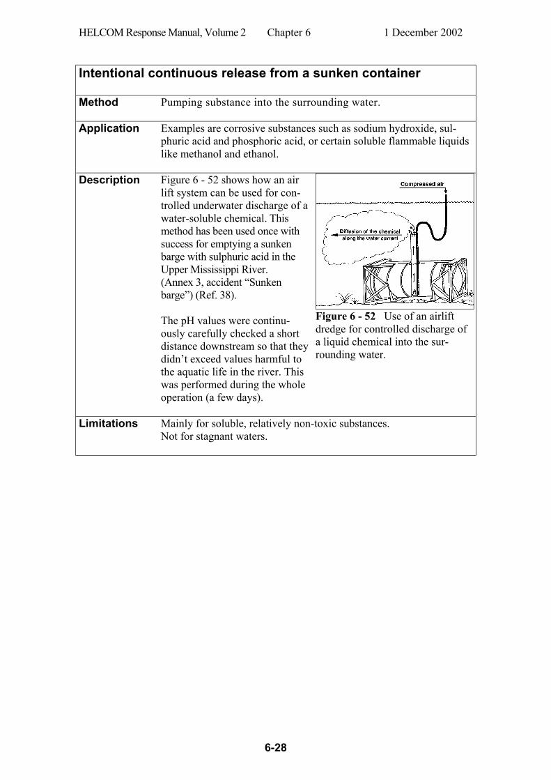
HELCOM Response Manual, Volume 2 Chapter 6 1 December 2002
6-28
Intentional continuous release from a sunken container Method Pumping substance into the surrounding water.
Application Examples are corrosive substances such as sodium hydroxide, sul-
phuric acid and phosphoric acid, or certain soluble flammable liquids like methanol and ethanol.
Description
Figure 6 - 52 shows how an air lift system can be used for con-trolled underwater discharge of a water-soluble chemical. This method has been used once with success for emptying a sunken barge with sulphuric acid in the Upper Mississippi River. (Annex 3, accident “Sunken barge”) (Ref. 38). The pH values were continu-ously carefully checked a short distance downstream so that they didn’t exceed values harmful to the aquatic life in the river. This was performed during the whole operation (a few days).
Figure 6 - 52 Use of an airlift dredge for controlled discharge of a liquid chemical into the sur-rounding water.
Limitations Mainly for soluble, relatively non-toxic substances. Not for stagnant waters.
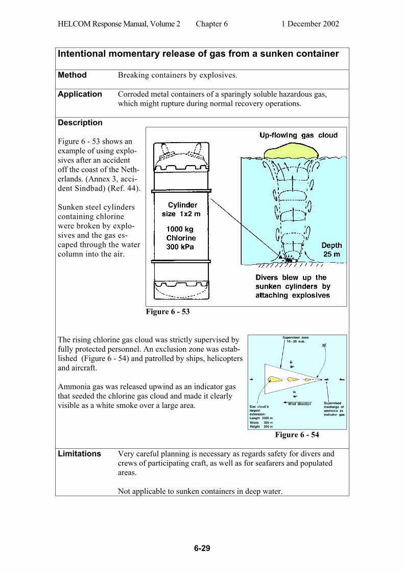
HELCOM Response Manual, Volume 2 Chapter 6 1 December 2002
6-29
Intentional momentary release of gas from a sunken container Method Breaking containers by explosives.
Application Corroded metal containers of a sparingly soluble hazardous gas,
which might rupture during normal recovery operations.
Description Figure 6 - 53 shows an example of using explo-sives after an accident off the coast of the Neth-erlands. (Annex 3, acci-dent Sindbad) (Ref. 44). Sunken steel cylinders containing chlorine were broken by explo-sives and the gas es-caped through the water column into the air.
Figure 6 - 53
The rising chlorine gas cloud was strictly supervised by fully protected personnel. An exclusion zone was estab-lished (Figure 6 - 54) and patrolled by ships, helicopters and aircraft. Ammonia gas was released upwind as an indicator gas that seeded the chlorine gas cloud and made it clearly visible as a white smoke over a large area.
Figure 6 - 54
Limitations Very careful planning is necessary as regards safety for divers and
crews of participating craft, as well as for seafarers and populated areas. Not applicable to sunken containers in deep water.
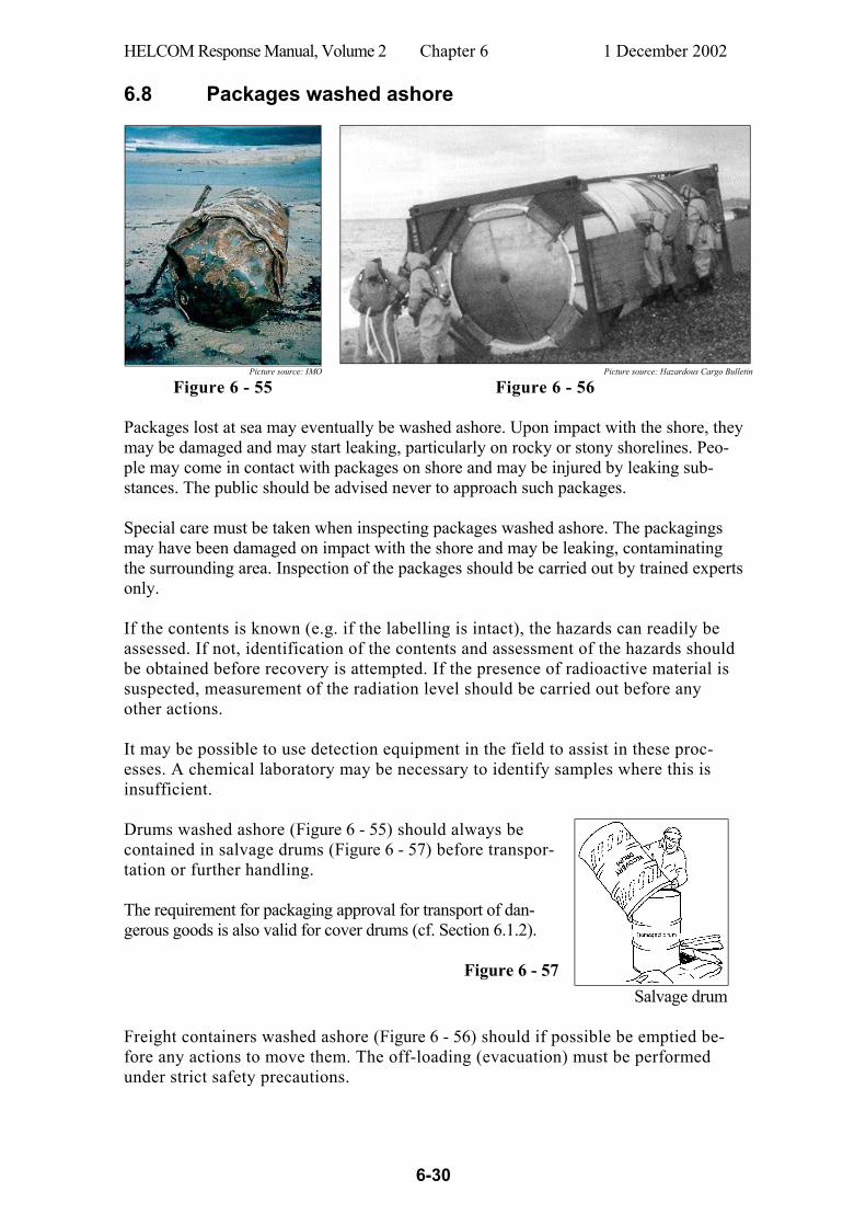
HELCOM Response Manual, Volume 2 Chapter 6 1 December 2002
6-30
6.8 Packages washed ashore
Picture source: IMO Picture source: Hazardous Cargo Bulletin
Figure 6 - 55 Figure 6 - 56 Packages lost at sea may eventually be washed ashore. Upon impact with the shore, they may be damaged and may start leaking, particularly on rocky or stony shorelines. Peo-ple may come in contact with packages on shore and may be injured by leaking sub-stances. The public should be advised never to approach such packages. Special care must be taken when inspecting packages washed ashore. The packagings may have been damaged on impact with the shore and may be leaking, contaminating the surrounding area. Inspection of the packages should be carried out by trained experts only. If the contents is known (e.g. if the labelling is intact), the hazards can readily be assessed. If not, identification of the contents and assessment of the hazards should be obtained before recovery is attempted. If the presence of radioactive material is suspected, measurement of the radiation level should be carried out before any other actions. It may be possible to use detection equipment in the field to assist in these proc-esses. A chemical laboratory may be necessary to identify samples where this is insufficient. Drums washed ashore (Figure 6 - 55) should always be contained in salvage drums (Figure 6 - 57) before transpor-tation or further handling. The requirement for packaging approval for transport of dan-gerous goods is also valid for cover drums (cf. Section 6.1.2).
Figure 6 - 57 Salvage drum
Freight containers washed ashore (Figure 6 - 56) should if possible be emptied be-fore any actions to move them. The off-loading (evacuation) must be performed under strict safety precautions.
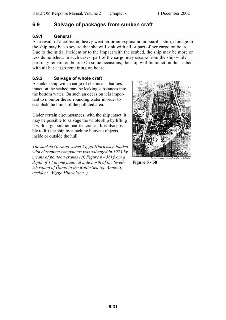
HELCOM Response Manual, Volume 2 Chapter 6 1 December 2002
6-31
6.9 Salvage of packages from sunken craft 6.9.1 General As a result of a collision, heavy weather or an explosion on board a ship, damage to the ship may be so severe that she will sink with all or part of her cargo on board. Due to the initial incident or to the impact with the seabed, the ship may be more or less demolished. In such cases, part of the cargo may escape from the ship while part may remain on board. On some occasions, the ship will lie intact on the seabed with all her cargo remaining on board. 6.9.2 Salvage of whole craft A sunken ship with a cargo of chemicals that lies intact on the seabed may be leaking substances into the bottom water. On such an occasion it is impor-tant to monitor the surrounding water in order to establish the limits of the polluted area. Under certain circumstances, with the ship intact, it may be possible to salvage the whole ship by lifting it with large pontoon-carried cranes. It is also possi-ble to lift the ship by attaching buoyant objects inside or outside the hull. The sunken German vessel Viggo Hinrichsen loaded with chromium compounds was salvaged in 1973 by means of pontoon cranes (cf. Figure 6 - 58) from a depth of 17 m one nautical mile north of the Swed-ish island of Öland in the Baltic Sea (cf. Annex 3, accident “Viggo Hinrichsen”).
Picture source: Hazardous Cargo Bulletin
Figure 6 - 58
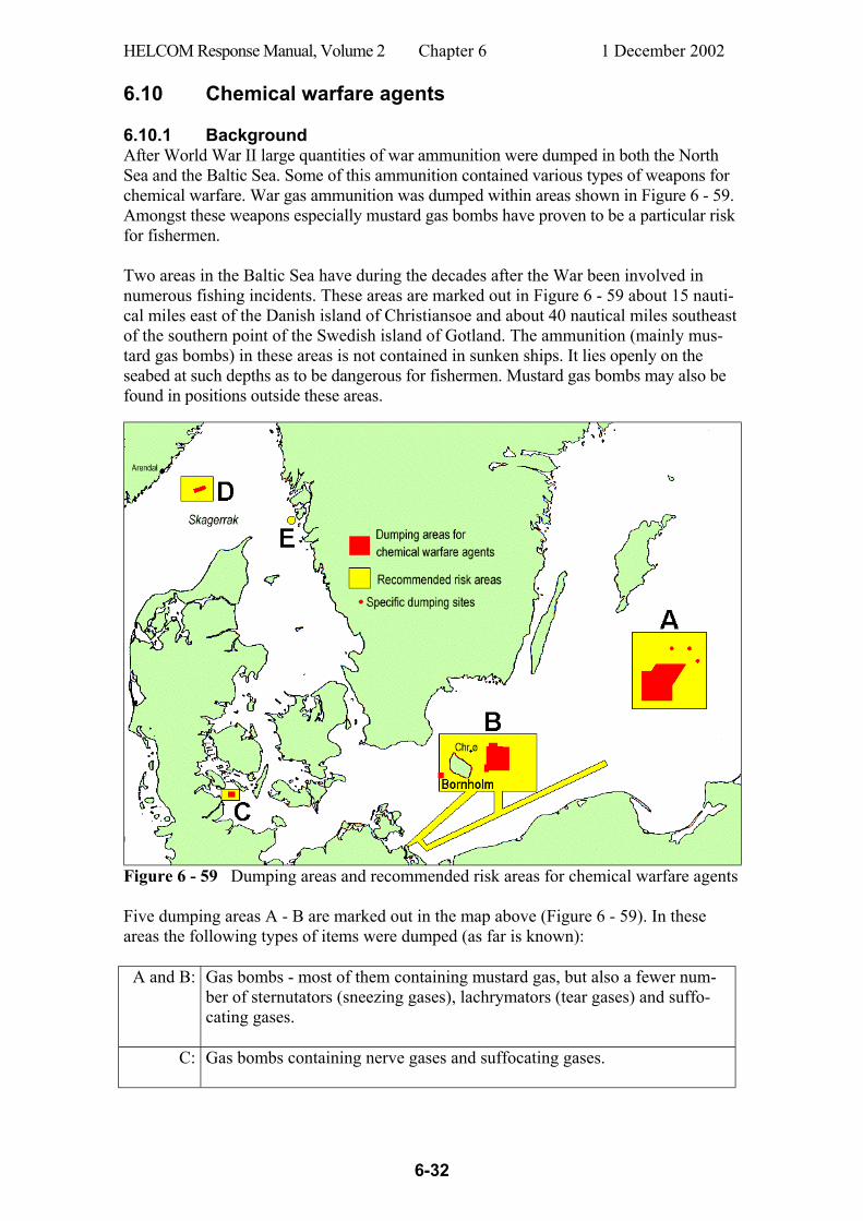
HELCOM Response Manual, Volume 2 Chapter 6 1 December 2002
6-32
6.10 Chemical warfare agents 6.10.1 Background After World War II large quantities of war ammunition were dumped in both the North Sea and the Baltic Sea. Some of this ammunition contained various types of weapons for chemical warfare. War gas ammunition was dumped within areas shown in Figure 6 - 59. Amongst these weapons especially mustard gas bombs have proven to be a particular risk for fishermen. Two areas in the Baltic Sea have during the decades after the War been involved in numerous fishing incidents. These areas are marked out in Figure 6 - 59 about 15 nauti-cal miles east of the Danish island of Christiansoe and about 40 nautical miles southeast of the southern point of the Swedish island of Gotland. The ammunition (mainly mus-tard gas bombs) in these areas is not contained in sunken ships. It lies openly on the seabed at such depths as to be dangerous for fishermen. Mustard gas bombs may also be found in positions outside these areas.
Figure 6 - 59 Dumping areas and recommended risk areas for chemical warfare agents Five dumping areas A - B are marked out in the map above (Figure 6 - 59). In these areas the following types of items were dumped (as far is known):
A and B: Gas bombs - most of them containing mustard gas, but also a fewer num-ber of sternutators (sneezing gases), lachrymators (tear gases) and suffo-cating gases.
C: Gas bombs containing nerve gases and suffocating gases.
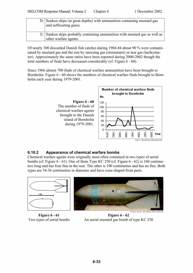
HELCOM Response Manual, Volume 2 Chapter 6 1 December 2002
6-33
D: Sunken ships (at great depths) with ammunition containing mustard gas and suffocating gases.
E: Sunken ships probably containing ammunition with mustard gas as well as other warfare agents.
Of nearly 300 discarded Danish fish catches during 1968-84 about 90 % were contami-nated by mustard gas and the rest by sneezing gas (sternutator) or tear gas (lachryma-tor). Approximately the same ratios have been reported during 2000-2002 though the total numbers of finds have decreased considerably (cf. Figure 6 - 60). Since 1966 almost 700 finds of chemical warfare ammunition have been brought to Bornholm. Figure 6 - 60 shows the numbers of chemical warfare finds brought to Born-holm each year during 1979-2001.
Figure 6 - 60 The number of finds of
chemical warfare agents brought to the Danish
island of Bornholm during 1979-2001.
Source: Bornholms Marinedistrikt
6.10.2 Appearance of chemical warfare bombs Chemical warfare agents were originally most often contained in two types of aerial bombs (cf. Figure 6 - 61). One of them Type KC 250 (cf. Figure 6 - 62) is 160 centime-tres long and has four fins in the rear. The other is 100 centimetres and has no fins. Both types are 34-36 centimetres in diameter and have cone-shaped front parts.
Picture source: Bornholms Marinedistrikt
Figure 6 - 61 Two types of aerial bombs
Figure 6 - 62 An aerial mustard gas bomb of type KC 250
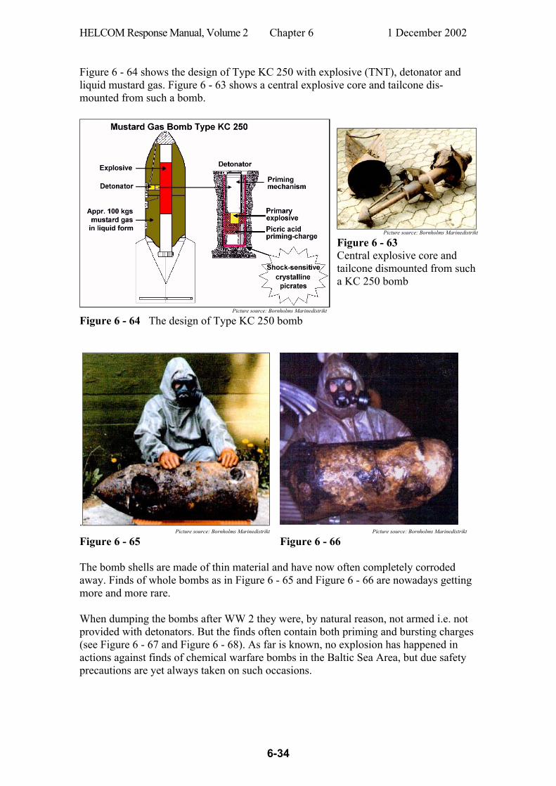
HELCOM Response Manual, Volume 2 Chapter 6 1 December 2002
6-34
Figure 6 - 64 shows the design of Type KC 250 with explosive (TNT), detonator and liquid mustard gas. Figure 6 - 63 shows a central explosive core and tailcone dis-mounted from such a bomb.
Picture source: Bornholms Marinedistrikt
Figure 6 - 63
Central explosive core and tailcone dismounted from such a KC 250 bomb
Picture source: Bornholms Marinedistrikt
Figure 6 - 64 The design of Type KC 250 bomb
. Picture source: Bornholms Marinedistrikt Picture source: Bornholms Marinedistrikt
Figure 6 - 65 Figure 6 - 66 The bomb shells are made of thin material and have now often completely corroded away. Finds of whole bombs as in Figure 6 - 65 and Figure 6 - 66 are nowadays getting more and more rare. When dumping the bombs after WW 2 they were, by natural reason, not armed i.e. not provided with detonators. But the finds often contain both priming and bursting charges (see Figure 6 - 67 and Figure 6 - 68). As far is known, no explosion has happened in actions against finds of chemical warfare bombs in the Baltic Sea Area, but due safety precautions are yet always taken on such occasions.
HELCOM Response Manual, Volume 2 Chapter 6 1 December 2002
6-35
Picture source: Bornholms Marinedistrikt Picture source: Bornholms Marinedistrikt
Figure 6 - 67 Figure 6 - 68 Among chemical warfare finds in the Baltic Sea, bombs of Type KC 250 (or their re-mains) are the most common. But also other types of ammunition occur but more sel-dom. Figure 6 - 69 shows the construction of a so called “jumping mine” and Figure 6 - 70 shows a find of a weathered lump of mustard gas from such a mine. A jumping mine is designed to be dug down. It is trip-wire released and is then thrown 10-15 m upwards where it detonates and distributes mustard gas over appr. 150 square metres.
Picture source: Bornholms Marinedistrikt Picture source: Bornholms Marinedistrikt
Figure 6 - 69 Construction of a jump-ing mine with mustard gas
Figure 6 - 70 A weathered mustard gas lump from a jumping mine
Picture source: Bornholms Marinedistrikt
Danish information docu-ments aimed for fishermen also contain brief data on war gas artillery shells (diam. 10.5 cm, length 35-50 cm, cf. Figure 6 - 71).
Figure 6 - 71 A war gas artillery shell Fishermen in the Baltic Sea sometimes get mustard gas in their fish catch. The recent finds of mustard gas sometimes resemble clay. They could also be solid, dark yel-low/brown lumps as in Figure 6 - 72, Figure 6 - 73 and Figure 6 - 74. Such lumps vary in size up to 80 kgs. On some occasions they may easily fall apart in pieces and may

HELCOM Response Manual, Volume 2 Chapter 6 1 December 2002
6-36
expose a high viscosity liquid from the inner parts where the mustard gas is still un-weathered and extremely hazardous and can pose severe injuries.
Weathered (hydrolized and oxidized) lumps of mustard gas
Picture source: Bornholms Marinedistrikt Picture source: Bornholms Marinedistrikt Picture source: Bornholms Marinedistrikt
Figure 6 - 72 Figure 6 - 73 Figure 6 - 74 Sternutators (sneezing gases) have never been found in weapons in the Baltic Sea, but only in storage wooden cases. These cases have been decayed by now and finds of sneezing gases show up as lumps (cf. Figure 6 - 75).
Picture source: Bornholms Marinedistrikt
Figure 6 - 75 Sneezing gas 6.10.3 Properties of chemical warfare agents Appearance and behaviour of mustard gas Consistency In spite of its name, mustard gas is not a gas. In the mustard gas
bombs a more or less viscous fluid or sludge is found which may have the consistency of oil, mush, Vaseline or lumps of jelly. When exposed to the environment mustard gas oxidize and solidify.
Colour Yellow to brown or dark-brown (sometimes almost black).
Odour Sharp, sweet odour which may resemble cress, garlic, horseradish or mustard. The agent is insidious since sense of smell may be fatigued and fail to give warning of dangerous concentrations.
Behaviour Mustard gas often contains special additives which makes it easily stick to skin, clothing and gear. Mustard gas in liquid state will penetrate rapidly through fabric and leather. Ordinary rubber and many types of plastic provide short-time protection.
Medical effects of mustard gas Mustard gas is very hazardous to health both when exposed to the liquid and its vapour. Mustard gas penetrates easily into the body via the skin, mucous membranes and respi-

HELCOM Response Manual, Volume 2 Chapter 6 1 December 2002
6-37
ratory tract. Symptoms do not show immediately. Often the injuries do not appear until several hours after the exposure. In mustard gas accidents it is very important to start first aid as soon as possible because injuries caused by mustard gas can take a very long time to heal. Skin Even minor amounts of mustard gas cause itching and burning red spots,
or even shooting pain, a few hours after exposure to the skin. After an-other few hours large liquid-filled blisters may develop. If the blisters break, slow-healing wounds are formed which can easily be infected. Therefore the blisters should be prevented from breaking in every way.
Eyes When exposed to vapours of mustard gas, the victim at first feels the eyes itching and smarting. After increasing smarting pain and reddening of the eyes a copious flow of tears will arise as well as sensitivity for light, tem-porary blindness, and a heavy swelling of the eyelids. If the eyes are ex-posed to liquid mustard gas they will be injured with a severe risk of blindness.
Lungs The risk of injuries by mustard gas vapours is highest in warm weather, stationary air and confined spaces. Inhalation of hazardous concentrations of mustard gas vapours gives rise to nasal catarrh (runny nose), hoarse-ness, sore throat and coughing. The coughing may became painful, the power of speech may be lost and the breathing may be deteriorated. The result may be serious injuries to the windpipe and lungs.
In severe cases of skin in exposure or inhalation, a general poisoning will develop in the body after some hours, besides the above mentioned symptoms. In these cases the victim may be affected by general sickness, lethargy, loss of appetite, nausea, fever, vomiting and bloody diarrhoea in combination with severe pains in the chest and stomach. Lachrymators (tear gases) are volatile substances which affect the mucous membrane of the eyes and cause watery painful eyes. They may irritate the skin and cause local injuries. The effects do not last very long after the affected person has been removed from the gas. Sternutators (sneezing gases) affect the mucous membranes of the nose, throat and respiratory passages and causes sneezing, coughing, a runny nose and watery eyes. These effects can last from 15 minutes to a couple of hours after the affected person has moved away from the gas to fresh air. Nerve agent of the tabun type is, in its pure form, a transparent and odourless glycer-ine-like substance. However, impurities sometimes make the liquid dark and give it a fruity smell, and any additives to it may al so affect its smell. Nerve agents are easily absorbed through the skin. respiratory organs, eyes and the gastro-intestinal tract. Nerve agents in liquid and vaporised form easily penetrate all textiles and leather. Ordinary robber and many types of plastic only provide brief pro-tection. A small dose of nerve agent will cause headaches. painful eyes. blurred vision. pupil contractions, a running nose and a feeling of weight on the chest.
HELCOM Response Manual, Volume 2 Chapter 6 1 December 2002
6-38
A large dose will cause the above symptoms followed by cramps, difficulty in breath-ing, a slow pulse, and may be fatal as a result of respiratory or cardiac arrest. If a person is exposed to a large dose, the entire poisoning process is very quick. usually between 5 and 10 minutes, unless the patient is treated. Suffocating agents. A typical suffocating agent is phosgene, which is a colourless gas. Phosgene is a liquid below 8oC,. In low concentrations it has a rather sweet, not un-pleasant smell, which is reminiscent of newly cut hay. In high concentrations the smell becomes sharper and irritating. The fumes are heavier than air. The substance is very insidious, and harmful quantities can be inhaled without the person noticing anything. For the first few hours after a person has been exposed to phosgene fumes, the only effect is irritation of the mucous membranes in the respiratory passages. The symptoms of poisoning are difficulty in breathing, coughing, a feeling of suffocation, thirst, vomit-ing, pain in the chest, lips turning blue, foaming at the mouth, extreme weakness, men-tal disturbances followed by unconsciousness. The reason for this is that phosgene causes pulmonary oedema and prevents oxygen absorption because of damage to the lung tissue. The mucous membranes of the eyes are also affected by phosgene, which can result in permanent eye damage, even though there are no symptoms of this at the start. Smoke-generating agents contain often phosphorous compounds. A mixture of sulphur trioxide and chlorosulphonic acid is another powerful smoke generator. In its liquid form it is extremely corrosive on contact with the skin. In its vaporised form, it consists of small particles of hydrochloric acid and sulphuric acid, which irritate the skin, eyes and respiratory organs. Phosphorous is found in smoke ammunition where the who le charge or part of it consists of yellow (white) phosphorous. When phosphorous is taken out of the-water and comes into contact with the oxygen in the air, it ignites. Phosphorous sores heal very slowly. The information above does not deal with the possible chronic adverse effects of the poisons. 6.10.4 Actions in incidents involving finds of chemical warfare agents First steps 1. Responsible bodies are alerted according to pre-arranged plans. If the find is
suspected to contain explosives it must not be moved until it has been exam-ined by appropriate expertise.
2. A vessel is commissioned for a first action involving transport of personnel, warning of seafarers and necessary assistance to involved fishing vessels.
3. If the affected fishing vessel can run by its own engines it is primarily directed

HELCOM Response Manual, Volume 2 Chapter 6 1 December 2002
6-39
to a suitable decontamination anchorage where environmental response vessels are utilized for decontamination actions.
4. Vessels are commanded for transport of disarming personnel and safety equip-ment. The vessels carry safety equipment for own personnel.
5. Chemical warfare finds, contaminated waste, discarded catch etc. is brought to land and taken care of according to local regulations.
Immediate on-site decontamination of personnel contaminated by mustard gas It is very important that contaminated skin and eyes are immediately cleaned before the mustard gas has penetrated into the body. Every minute's delay will increase the risk of injuries. If both the skin and eyes are contaminated, assistance should be re-ceived from someone not injured so that the first actions can be taken simultaneously according to the guidance below. Do not touch the face and eyes with contaminated hands. Get medical aid as soon as possible. N.B.! Stay in the open air on deck if the clothes are contaminated. It is important that not to scatter the mustard gas to clean spaces on the vessel. Skin First take off all contaminated garments as well as rings, watches etc. There must be a full certainty that no contaminated garments or objects remain on the body. Act rap-idly but cautiously so that the face and eyes do not become contaminated. Remove quickly the (sometimes sticky) mustard gas which can be scraped from the skin with a knife or similar. Act cautiously and avoid rubbing it into the skin or to spread it. Low viscous mustard gas should be "tweaked" away with an absorbent material in order to prevent spreading on the skin. Also this must be done quickly. Use thereafter a special decontamination agent for mustard gas, if available on board. Observe care- fully the instructions which apply for the agent. Wash decontaminated skin areas with usual soap or soft soap and water. Observe that mucous membranes and the lower abdomen are especially sensitive to mustard gas. Finish up by careful washing of all the body with soap and water. Apply wet bandages on injured skin areas. Blisters should not be broken. Wash immediately contaminated eyes with a soft spray of clean and preferably luke-warm fresh water for at least 15 minutes. Keep the eyelids widely apart during wash-ing. Use an eye wash station if available on board. Then close the eyelids and clean the surrounding skin parts cautiously with soap and water. Do not use any kind of eye ointment, decontamination agent or bandage.
HELCOM Response Manual, Volume 2 Chapter 6 1 December 2002
6-40
Decontamination of vessel and equipment which are contaminated by mustard gas On first hand an area of at least 30 m radius should be cordoned off.
Continuously monitor the air outside the cordon. The cordon must be expanded
if any instrument indication is obtained or suspected smell is noticed.
The following apply for decontamination of vessel and equipment:
- Indicating equipment is used to judge the need for decontamination as well as to check for any remaining contaminants after decontamination actions.
- The personnel must wear full personal protective equipment including self-contained breathing apparatus.
Below are 6 different decontamination methods and agents described that have to be used depending on the properties of the contaminated surface. A reference to a detailed report on destruction methods for chemical weapons is given in Ref. 61. Mustard gas (and other chemical warfare agents) penetrate rapidly through porous materials like wood, fabrics, rubber, etc. It is therefore difficult to decontaminate such materials and it has to be performed by means of penetrating decontaminants or meth-ods like DS2 or boiling. DS2 is a mixture of diethylenetriamine (70%), sodium hydrox-ide (2%) and ethylene glycol monomethyl ether (28%). These decontamination methods can have unwanted effects on the materials’ properties. Hard surfaces are not so difficult to decontaminate as they don’t imbibe mustard gas and other chemical warfare agents. Feasible methods are high-pressure steam or hotwater spraying, or treatment with DS2 or chloride of lime. DS2 or chloride of lime should be distributed over the contaminated items and should act for 15-30 minutes before flushing with high-pressure water. Decontamination equipment like deck brushes, buckets, cotton waste, etc. as well as well as equipment that is difficult to decontaminate should be regarded and treated as contaminated waste. 1. Airing
Gaseous mustard gas in the air of closed spaces is remove by violent airing.
2. Washing Contaminated items are washed with cotton waste soaked with hot soap or detergent solution, or soaked with light diesel fuel oil, kerosene, etc. Alterna-tively the items are flushed with hot soap solution during simultaneous working with a brush. Discarded cotton waste etc., soaked with kerosene or diesel fuel oil, used for washing should be collected in tin containers as these solvents might affect plastic containers.

HELCOM Response Manual, Volume 2 Chapter 6 1 December 2002
6-41
3. High-pressure water spraying
Spraying with water (preferably heated) under high pressure. The angle be-tween the jet and the item’s surface should not exceed 30°.
4. High-pressure steam or hotwater spraying Treatment of contaminated items with steam or hotwater under pressure (pref-erably high pressure).
5. Decontamination with chloride of lime A slurry of chloride of lime (sodium hypochlorite can also be used) in at least 3 parts of water is distributed over the contaminated item’s surface. The slurry is worked into the surface with a brush and should act for 15-30 minutes before careful washing or flushing. N.B.: Chloride of lime and sodium hypochlorite are corrosive for eyes and skin. Both agents corrode metals and may damage fabrics etc. Dry chloride of lime may ignite upon contact with mustard gas.
6. Decontamination with DS2 DS2 is distributed on the contaminated item’s surface (0.05 – 0.1 litre/m²) and should act for 15-30 minutes before careful washing or flushing. N.B.: DS2 is harmful to breathe and is corrosive to eyes and skin. It is alkaline and corrosive to certain metals (e.g. light metals) and may damage certain other materials. DS2 may react violently (fire or explosion) when mixed with chlo-ride of lime or hypochlorites and if ignited by sparks or fire.

HELCOM Response Manual, Volume 2 ANNEX 1 1 December 2002
A1-1
First response actions in chemical accidents A. Organisation chart for Emergency Responders
and their command An OSC should be appointed who is especially trained for maritime accident involving chemicals and dangerous gods. The OSC should supervise both own Emergency Re-sponders and all supporting outside groups of Emergency Responders (cf. Figure a1 - 1).
Figure a1 - 1 B. Threatening picture The actual risk environment is crucial when judging the necessary extent and safety of a Emergency Responder action. The risk level vary considerably depending on the target of operation and the type of work needed. Furthermore due consideration should be given to the character and scope of the emergency. For practical reasons the design of the responder action should be based on one of two levels of priority for the risk environment: High risk work area with any one of the following properties: - Action site (e.g. on board a ship) with longer penetration than the length of a life line. - Bad sight. - Risk for closed lines of retreat for responders. - Risk for special difficulties depending on the ship’s construction or the type of target. Other risk areas than a high risk environment is such an environment that could not be clearly classified as a high risk environment. Actions on board ships involved in chemical accidents should always be carried out by Emergency Responders.
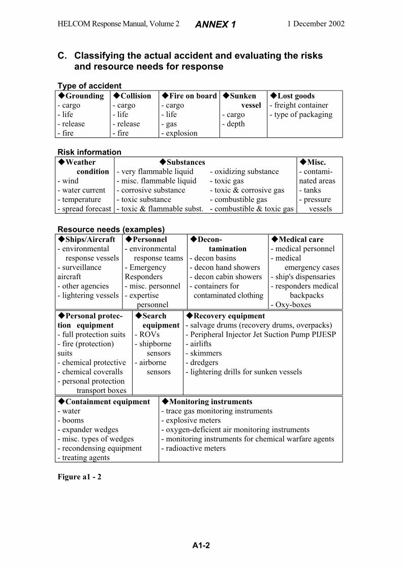
HELCOM Response Manual, Volume 2 ANNEX 1 1 December 2002
A1-2
C. Classifying the actual accident and evaluating the risks
and resource needs for response Type of accident
Grounding - cargo - life - release - fire
Collision - cargo - life - release - fire
Fire on board - cargo - life - gas - explosion
Sunken vessel - cargo - depth
Lost goods - freight container - type of packaging
Risk information
Weather condition - wind - water current - temperature - spread forecast
Substances - very flammable liquid - misc. flammable liquid - corrosive substance - toxic substance - toxic & flammable subst.
- oxidizing substance - toxic gas - toxic & corrosive gas - combustible gas - combustible & toxic gas
Misc. - contami-nated areas - tanks - pressure vessels
Resource needs (examples)
Ships/Aircraft - environmental response vessels - surveillance aircraft - other agencies - lightering vessels
Personnel - environmental response teams - Emergency Responders - misc. personnel - expertise
personnel
Decon- tamination - decon basins - decon hand showers - decon cabin showers - containers for contaminated clothing
Medical care - medical personnel - medical emergency cases - ship's dispensaries - responders medical backpacks - Oxy-boxes
Personal protec-tion equipment - full protection suits - fire (protection) suits - chemical protective - chemical coveralls - personal protection transport boxes
Search equipment - ROVs - shipborne sensors - airborne
sensors
Recovery equipment - salvage drums (recovery drums, overpacks) - Peripheral Injector Jet Suction Pump PIJESP - airlifts - skimmers - dredgers - lightering drills for sunken vessels
Containment equipment - water - booms - expander wedges - misc. types of wedges - recondensing equipment - treating agents
Monitoring instruments - trace gas monitoring instruments - explosive meters - oxygen-deficient air monitoring instruments - monitoring instruments for chemical warfare agents - radioactive meters
Figure a1 - 2
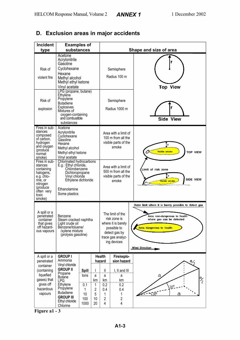
HELCOM Response Manual, Volume 2 ANNEX 1 1 December 2002
A1-3
D. Exclusion areas in major accidents
Incident
type Examples of substances
Shape and size of area
Risk of
violent fire
Acetone Acrylonitrile Gasoline Cyclohexane Hexane Methyl alcohol Methyl ethyl ketone Vinyl acetate
Semisphere
Radius 100 m
Risk of
explosion
LPG (propane, butane) Ethylene Propylene Butadiene Explosives Mixtures of oxygen-containing and combustible substances
Semisphere
Radius 1000 m
Fires in sub-stances composed of carbon, hydrogen and oxygen (produce normal smoke)
Acetone Acrylonitrile Cyclohexane Gasoline Hexane Methyl alcohol Methyl ethyl ketone Vinyl acetate
Area with a limit of 100 m from all the visible parts of the
smoke
Fires in sub-stances containing halogens, e.g. chlo-rine, or nitrogen (produce often very toxic smoke)
Chlorinated hydrocarbons E.g.: Ethyl chloride, Chlorobenzene Dichloropropane Vinyl chloride Ethylene dichloride Ethanolamine Some plastics
Area with a limit of 500 m from all the visible parts of the
smoke
A spill or a penetrated container that gives off hazard-
ous vapours
Benzene Steam cracked naphtha Light crude oil Benzene/toluene/ /xylene mixture (prolysis gasoline)
The limit of the risk zone is
where it is barely possible to
detect gas by trace gas analyz-
ing devices
Health hazard
Fire/explo-sion hazard
Spill
I
II
I, II and III
tons a km
a km
a km
A spill or a penetrated container
(containing liquefied
gases) that gives off
hazardous vapours
GROUP I Ammonia Vinyl chloride GROUP II Propane Butane LPG Ethylene Propylene Butadiene GROUP III Ethyl chloride Chlorine
0.1 1 10 100 1000
1 2 5 10 20
0.2 0.4 1 2 4
0.2 0.4 1 2 4
Figure a1 - 3
HELCOM Response Manual, Volume 2 ANNEX 1 1 December 2002
A1-4
E. Order of priority for actions 1. Life saving:
- Search for victims - Carriage of victims from the risk area - First aid - Decontamination of victims - Transportation of victims
2. 3.
Stop, limit and combat discharges (e.g. collect, neutralize, wash overboard) Reduce damage (Fight fire, cool goods, move goods)
F. Personal protection equipment for Emergency Responders The decision on choice of personal protection equipment should be taken by the Re-sponder OSC considering check lists and actual threatening picture (risk environment). The personal protection equipment could be e.g. a) fire protection suit with self-contained breathing apparatus, b) fire suit with a cover and breathing equipment, or c) chemical coverall with breathing equipment. G. To enter a ship involved in a chemical accident General tactics consider-ing the wind direction At a chemical accident on board a ship a hazardous clouds (visible or invisible) may be generated and moved by the wind. In such a case the ship should be moved so that the cloud moves obliquely from the crew’s accommoda-tions (cf. Figure a1 - 4). Boarding and accident response should also be performed from the opposite side of the cloud.
Figure a1 - 4 Boarding and accident response from the opposite side of the hazardous cloud.
Safety precautions Emergency Responders who board a ship in actions against accidents shall bring:
Appropriate personal protection equipment (cf. Annex 5 “Body protection levels”) Appropriate monitoring devices (e.g. for toxic, flammable and radioactive environment) Appropriate safety equipment (e.g. for communication, decontamination and life saving) Appropriate response equipment (e.g. for fire fighting, cooling and neutralizing)
Important safety measures:
Safe return spaces with clean areas shall be prepared on board First response backup teams shall be readily available and appropriately equipped A safe number of extra air bottles shall be easily available close to the responders
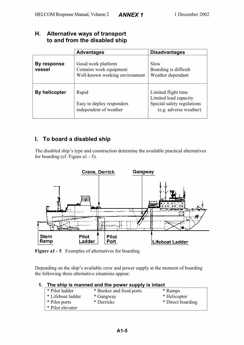
HELCOM Response Manual, Volume 2 ANNEX 1 1 December 2002
A1-5
H. Alternative ways of transport
to and from the disabled ship Advantages Disadvantages By response vessel
Good work platform Contains work equipment Well-known working environment
Slow Boarding is difficult Weather dependant
By helicopter
Rapid Easy to deploy responders independent of weather
Limited flight time Limited load capacity Special safety regulations (e.g. adverse weather)
I. To board a disabled ship The disabled ship’s type and construction determine the available practical alternatives for boarding (cf. Figure a1 - 5).
Figure a1 - 5 Examples of alternatives for boarding Depending on the ship’s available crew and power supply at the moment of boarding the following three alternative situations appear.
1. The ship is manned and the power supply is intact * Pilot ladder
* Lifeboat ladder * Pilot ports * Pilot elevator
* Bunker and food ports * Gangway * Derricks
* Ramps * Helicopter * Direct boarding
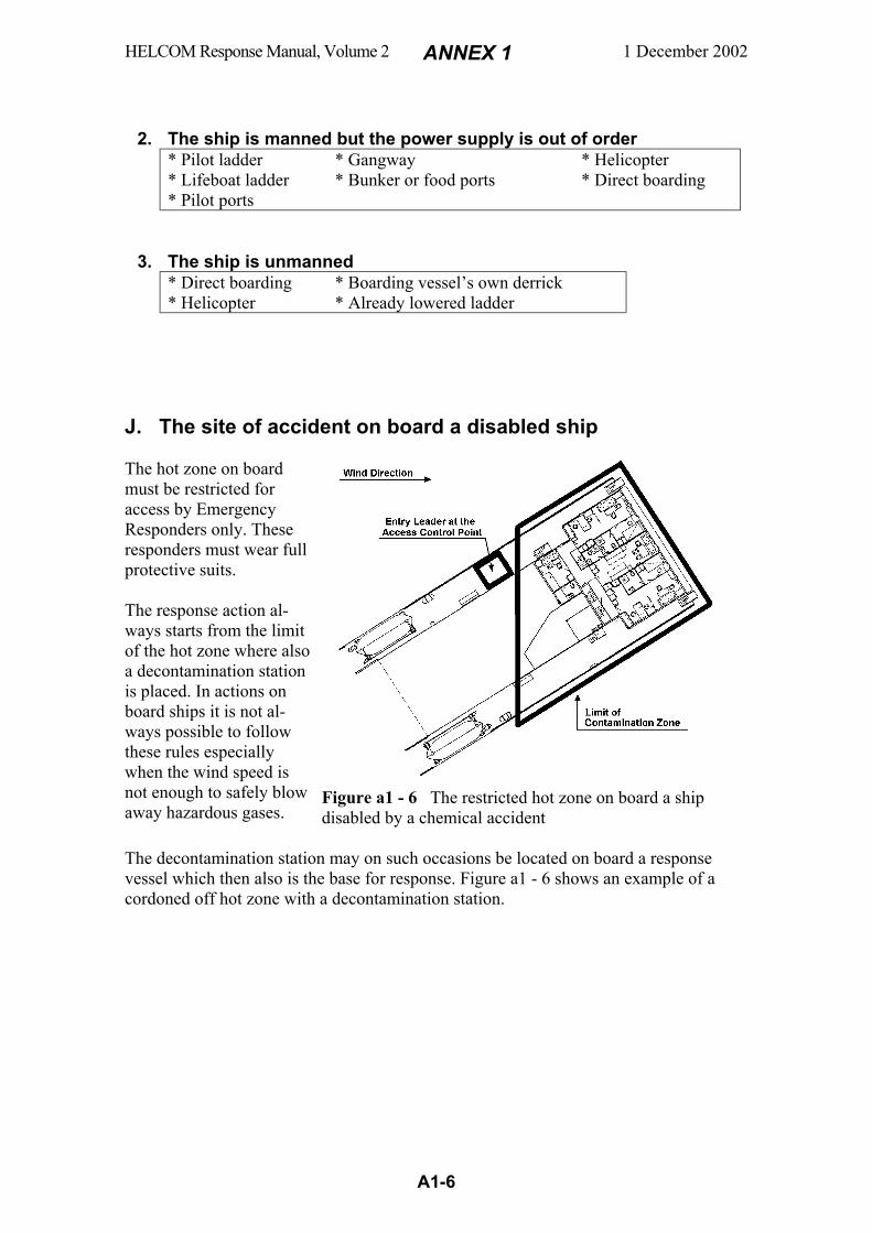
HELCOM Response Manual, Volume 2 ANNEX 1 1 December 2002
A1-6
2. The ship is manned but the power supply is out of order * Pilot ladder
* Lifeboat ladder * Pilot ports
* Gangway * Bunker or food ports
* Helicopter * Direct boarding
3. The ship is unmanned * Direct boarding
* Helicopter * Boarding vessel’s own derrick * Already lowered ladder
J. The site of accident on board a disabled ship The hot zone on board must be restricted for access by Emergency Responders only. These responders must wear full protective suits. The response action al-ways starts from the limit of the hot zone where also a decontamination station is placed. In actions on board ships it is not al-ways possible to follow these rules especially when the wind speed is not enough to safely blow away hazardous gases.
Figure a1 - 6 The restricted hot zone on board a ship disabled by a chemical accident
The decontamination station may on such occasions be located on board a response vessel which then also is the base for response. Figure a1 - 6 shows an example of a cordoned off hot zone with a decontamination station.

HELCOM Response Manual, Volume 2 ANNEX 1 1 December 2002
A1-7
K. Example of a checklist In an operation at sea against a chemical accident it is valuable to follow a checklist where the steps could be ticked off, one by one, during the course of operation. The list below might earn as an example. It is established by the National Strike Force of the United States Coast Guard and is called Hazardous Chemical Emergency Response Checklist.
1. Risk assessment completed....................................................................
2. PPE* selection completed......................................................................
3. Emergency Response Procedures completed.........................................
4. Work zones established .........................................................................
5. PPE* checks completed .........................................................................
6. Decontamination line assembly completed ...........................................
7. Instruments calibrated............................................................................
8. Communication plan completed ............................................................
9. Pre-entry medical monitoring completed...............................................
10. Initial entry objectives established.........................................................
11. Action levels established........................................................................
12. Sampling plan completed.......................................................................
13. Pre-entry brief completed ......................................................................
14. Practice run through decontamination line ............................................
15. Communications check..........................................................................
16. Authorization for entry ..........................................................................
17. Post-entry medical monitoring completed .............................................
18. Entry team debrief completed................................................................
19. Emergency Response and Site Safety Plan modifications.....................
20. Equipment decontamination/inventory completed ................................
21. Contaminated materials disposed ..........................................................
22. Potential Exposure Record forms completed.........................................
23. Debrief conducted with OSC.................................................................
Figure a1 - 7 *PPE = Personal Protection Equipment
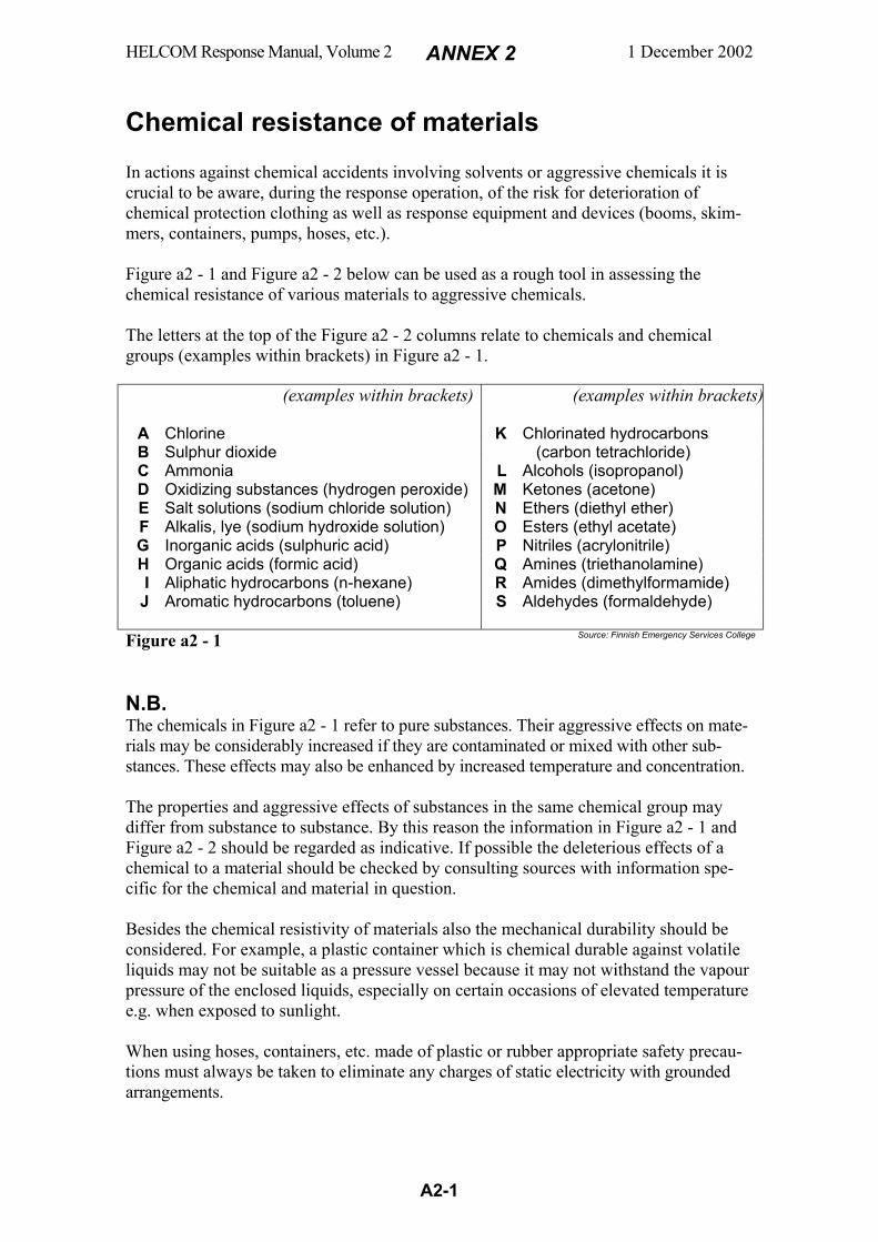
HELCOM Response Manual, Volume 2 ANNEX 2 1 December 2002
A2-1
Chemical resistance of materials In actions against chemical accidents involving solvents or aggressive chemicals it is crucial to be aware, during the response operation, of the risk for deterioration of chemical protection clothing as well as response equipment and devices (booms, skim-mers, containers, pumps, hoses, etc.). Figure a2 - 1 and Figure a2 - 2 below can be used as a rough tool in assessing the chemical resistance of various materials to aggressive chemicals. The letters at the top of the Figure a2 - 2 columns relate to chemicals and chemical groups (examples within brackets) in Figure a2 - 1.
(examples within brackets)
(examples within brackets)
A Chlorine K Chlorinated hydrocarbons B Sulphur dioxide (carbon tetrachloride) C Ammonia L Alcohols (isopropanol) D Oxidizing substances (hydrogen peroxide) M Ketones (acetone) E Salt solutions (sodium chloride solution) N Ethers (diethyl ether) F Alkalis, lye (sodium hydroxide solution) O Esters (ethyl acetate) G Inorganic acids (sulphuric acid) P Nitriles (acrylonitrile) H Organic acids (formic acid) Q Amines (triethanolamine) I Aliphatic hydrocarbons (n-hexane) R Amides (dimethylformamide)
J Aromatic hydrocarbons (toluene) S Aldehydes (formaldehyde)
Figure a2 - 1 Source: Finnish Emergency Services College
N.B. The chemicals in Figure a2 - 1 refer to pure substances. Their aggressive effects on mate-rials may be considerably increased if they are contaminated or mixed with other sub-stances. These effects may also be enhanced by increased temperature and concentration. The properties and aggressive effects of substances in the same chemical group may differ from substance to substance. By this reason the information in Figure a2 - 1 and Figure a2 - 2 should be regarded as indicative. If possible the deleterious effects of a chemical to a material should be checked by consulting sources with information spe-cific for the chemical and material in question. Besides the chemical resistivity of materials also the mechanical durability should be considered. For example, a plastic container which is chemical durable against volatile liquids may not be suitable as a pressure vessel because it may not withstand the vapour pressure of the enclosed liquids, especially on certain occasions of elevated temperature e.g. when exposed to sunlight. When using hoses, containers, etc. made of plastic or rubber appropriate safety precau-tions must always be taken to eliminate any charges of static electricity with grounded arrangements.
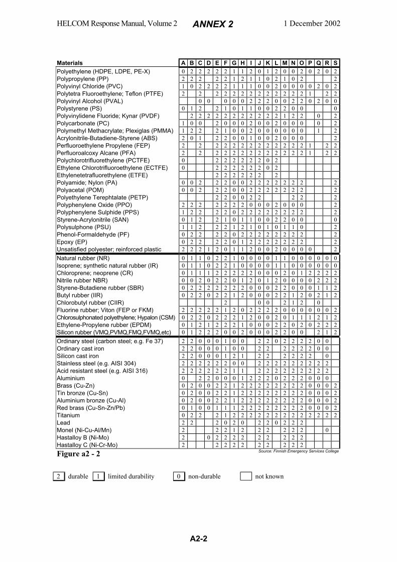
HELCOM Response Manual, Volume 2 ANNEX 2 1 December 2002
A2-2
Materials A B C D E F G H I J K L M N O P Q R S Polyethylene (HDPE, LDPE, PE-X) 0 2 2 2 2 2 1 1 2 0 1 2 0 0 2 0 2 0 2 Polypropylene (PP) 2 2 2 2 2 1 2 1 1 0 2 1 0 2 2 Polyvinyl Chloride (PVC) 1 0 2 2 2 2 1 1 1 0 0 2 0 0 0 0 2 0 2 Polytetra Fluoroethylene; Teflon (PTFE) 2 2 2 2 2 2 2 2 2 2 2 2 2 1 2 2 Polyvinyl Alcohol (PVAL) 0 0 0 0 0 2 2 2 0 0 2 2 0 2 0 0 Polystyrene (PS) 0 1 2 2 1 0 1 1 0 0 2 2 0 0 0 Polyvinylidene Fluoride; Kynar (PVDF) 2 2 2 2 2 2 2 2 2 2 2 1 2 2 0 2 Polycarbonate (PC) 1 0 0 2 0 0 0 2 0 0 2 0 0 0 0 2 Polymethyl Methacrylate; Plexiglas (PMMA) 1 2 2 2 1 0 0 2 0 0 0 0 0 0 1 2 Acrylonitrile-Butadiene-Styrene (ABS) 2 0 1 2 2 0 0 1 0 0 2 0 0 0 2 Perfluoroethylene Propylene (FEP) 2 2 2 2 2 2 2 2 2 2 2 2 2 1 2 2 Perfluoroalcoxy Alcane (PFA) 2 2 2 2 2 2 2 2 2 2 2 2 2 1 2 2 Polychlorotrifluorethylene (PCTFE) 0 2 2 2 2 2 2 0 2 Ethylene Chlorotrifluoroethylene (ECTFE) 0 2 2 2 2 2 2 0 2 Ethylenetetrafluorethylene (ETFE) 2 2 2 2 2 2 2 Polyamide; Nylon (PA) 0 0 2 2 2 0 0 2 2 2 2 2 2 2 2 Polyacetal (POM) 0 0 2 2 2 0 0 2 2 2 2 2 2 2 2 Polyethylene Terephtalate (PETP) 2 2 0 0 2 2 2 2 2 Polyphenylene Oxide (PPO) 2 2 2 2 2 2 2 0 0 0 2 0 0 0 2 Polyphenylene Sulphide (PPS) 1 2 2 2 2 0 2 2 2 2 2 2 2 2 2 Styrene-Acrylonitrile (SAN) 0 1 2 2 1 0 1 1 0 0 2 2 0 0 0 Polysulphone (PSU) 1 1 2 2 2 1 2 1 0 1 0 1 1 0 2 Phenol-Formaldehyde (PF) 0 2 2 2 2 0 2 2 2 2 2 2 2 2 2 Epoxy (EP) 0 2 2 2 2 0 1 2 2 2 2 2 2 2 2 Unsatisfied polyester; reinforced plastic 2 2 2 1 2 0 1 1 2 0 0 2 0 0 0 0 2 Natural rubber (NR) 0 1 1 0 2 2 1 0 0 0 0 1 1 0 0 0 0 0 0 Isoprene; synthetic natural rubber (IR) 0 1 1 0 2 2 1 0 0 0 0 1 1 0 0 0 0 0 0 Chloroprene; neoprene (CR) 0 1 1 1 2 2 2 2 2 0 0 0 2 0 1 2 2 2 2 Nitrile rubber NBR) 0 0 2 0 2 2 0 1 2 0 1 2 0 0 0 0 2 2 2 Styrene-Butadiene rubber (SBR) 0 2 2 2 2 2 2 2 0 0 0 2 2 0 0 0 1 1 2 Butyl rubber (IIR) 0 2 2 0 2 2 1 2 0 0 0 2 2 1 2 0 2 1 2 Chlorobutyl rubber (CIIR) 2 0 0 2 1 2 0 Fluorine rubber; Viton (FEP or FKM) 2 2 2 2 2 1 2 0 2 2 2 2 0 0 0 0 0 0 2 Chlorosulphonated polyethylene; Hypalon (CSM) 0 2 2 0 2 2 2 1 2 0 0 2 0 1 1 1 2 1 2 Ethylene-Propylene rubber (EPDM) 0 1 2 1 2 2 2 1 0 0 0 2 2 0 2 0 2 2 2 Silicon rubber (VMQ,PVMQ,FMQ,FVMQ,etc) 0 1 2 2 2 0 0 2 0 0 0 2 2 0 0 2 1 2 Ordinary steel (carbon steel; e.g. Fe 37) 2 2 0 0 0 1 0 0 2 2 0 2 2 2 2 0 0 Ordinary cast iron 2 2 0 0 0 1 0 0 2 2 2 2 2 2 0 0 Silicon cast iron 2 2 0 0 0 1 2 1 2 2 2 2 2 2 0 Stainless steel (e.g. AISI 304) 2 2 2 2 2 2 0 0 2 2 2 2 2 2 2 2 2 Acid resistant steel (e.g. AISI 316) 2 2 2 2 2 2 1 1 2 2 2 2 2 2 2 2 2 Aluminium 0 2 2 0 0 0 1 2 2 2 0 2 2 2 0 0 0 Brass (Cu-Zn) 0 2 0 0 2 2 1 2 2 2 2 2 2 2 2 0 0 0 2 Tin bronze (Cu-Sn) 0 2 0 0 2 2 1 2 2 2 2 2 2 2 2 0 0 0 2 Aluminium bronze (Cu-Al) 0 2 0 0 2 2 1 2 2 2 2 2 2 2 2 0 0 0 2 Red brass (Cu-Sn-Zn/Pb) 0 1 0 0 1 1 1 2 2 2 2 2 2 2 2 0 0 0 2 Titanium 0 2 2 2 1 2 2 2 2 2 2 2 2 2 2 2 2 2 Lead 2 2 2 0 2 0 2 2 0 2 2 2 Monel (Ni-Cu-Al/Mn) 2 2 2 1 2 2 2 2 2 2 0 Hastalloy B (Ni-Mo) 2 0 2 2 2 2 2 2 2 2 2 Hastalloy C (Ni-Cr-Mo) 2 2 2 2 2 2 2 2 2 2 Figure a2 - 2 Source: Finnish Emergency Services College
2 durable 1 limited durability 0 non-durable not known
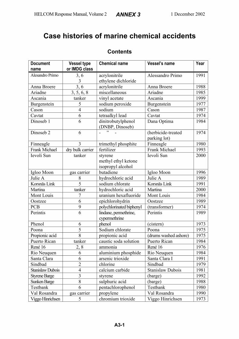
HELCOM Response Manual, Volume 2 ANNEX 3 1 December 2002
A3-1
Case histories of marine chemical accidents
Contents
Document name
Vessel type or IMDG class
Chemical name Vessel’s name Year
Alesandro Primo 3, 6 3
acrylonitrile ethylene dichloride
Alessandro Primo 1991
Anna Broere 3, 6 acrylonitrile Anna Broere 1988 Ariadne 3, 5, 6, 8 miscellaneous Ariadne 1985 Ascania tanker vinyl acetate Ascania 1999 Burgenstein 5 sodium peroxide Burgenstein 1977 Cason 4 sodium Cason 1987 Cavtat 6 tetraalkyl lead Cavtat 1974 Dinoseb 1 6 dinitrobutylphenol
(DNBP, Dinoseb) Dana Optima 1984
Dinoseb 2 6 - ” - (herbicide-treated parking lot)
1974
Finneagle 3 trimethyl phosphite Finneagle 1980 Frank Michael dry bulk carrier fertilizer Frank Michael 1993 Ievoli Sun tanker styrene
methyl ethyl ketone isopropyl alcohol
Ievoli Sun 2000
Igloo Moon gas carrier butadiene Igloo Moon 1996 Julie A 8 hydrochloric acid Julie A 1989 Korsnäs Link 5 sodium chlorate Korsnäs Link 1991 Martina tanker hydrochloric acid Martina 2000 Mont Louis 7 uranium hexafluoride Mont Louis 1984 Oostzee 6 epichlorohydrin Oostzee 1989 PCB 9 polychlorinated biphenyl (transformer) 1974 Perintis 6 lindane, permethrine,
cypermethrine Perintis 1989
Phenol 6 phenol (cistern) 1973 Poona 5 Sodium chlorate Poona 1975 Propionic acid 8 propionic acid (drums washed ashore) 1975 Puerto Rican tanker caustic soda solution Puerto Rican 1984 René 16 2, 8 ammonia René 16 1976 Rio Neuquen 6 aluminium phosphide Rio Neuquen 1984 Santa Clara 6 arsenic trioxide Santa Clara I 1991 Sindbad 2 chlorine Sindbad 1979 Stanislaw Dubois 4 calcium carbide Stanislaw Dubois 1981 Styrene Barge 3 styrene (barge) 1992 Sunken Barge 8 sulphuric acid (barge) 1988 Testbank 6 pentachlorophenol Testbank 1980 Val Rosandra gas carrier propylene Val Rosandra 1990 Viggo Hinrichsen 5 chromium trioxide Viggo Hinrichsen 1973

HELCOM Response Manual, Volume 2 ANNEX 3 1 December 2002
A3-2
Alessandro Primo Maritime Chemical Accident
1991, February 1 Adriatic Sea, 16 n.m. north-east of Molfetta, Italy Acrylonitrile (Class 3, 6) in tank containers; flammable liquid, toxic to both human and marine life, TLV 2 ppm (USA), IDLH 85 ppm (USA); marine pollutant Ethylene dichloride (Class 3) in tank containers; oily liquid, flammable and toxic, marine pollutant Summary: On February 1, 1991, the chemical carrier Alessandro Primo sank in the Adriatic Sea 16 miles off the coast of Italy. The water depth was 110 m and aboard the ship was a cargo of 550 tonnes of acrylonitrile and 3000 tonnes of ethylene dichloride. An exclusion zone of ten mile radius was set up around the wreck. During the following days water samples were taken around the wreck at various depths. Four days after the incident a trace of acrylonitrile was found 500 m from the wrecks position. Surveillance of the wreck with the aid of a ROV also showed evidence of an acrylonitrile leak. It was considered to be impossible to recover the entire ship which had been severely damaged when hitting the bottom. Diving at this depth also posed great difficulty. Three companies specialised in the area was hired to recover the cargo which threatened to pollute the area. The first step was to block the leaking of acrylonitrile and this was done by February 21. By the beginning of April the recovery operations started. With the aid of a large pontoon and a depot ship, the tanks of Allesandro Primo were emptied within less than a month. Many precautionary actions were taken during the hazardous opera-tion, such as a helicopter standing by and emergency personnel present. Despite the difficulties and the great risks no injuries were encountered. All of the remaining cargo was taken care of, although most acrylonitrile had leaked out before the recovery opera-tion started. Cause of Accident: Not available. Comments on Response: The incident was complicated due to many different circumstances, such as great depth and very dangerous chemicals. The handling of the situation was successful and very professionally done. The environmental impact of the incident was very small, especially regarding that two very pollutant chemicals were involved. Source of Information: 1) Report on the Alessandro Primo accident from REMPEC by G. Tosco. 2) Report from EniChem, Milano, 1996. 3) Project documentation from Smit Tak, Rotterdam. (Abstracted July 2001 by Edvard Molitor, Swedish Coast Guard HQ)
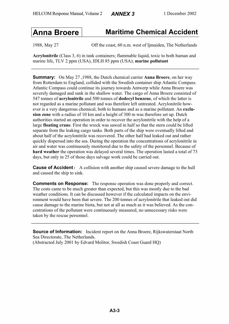
HELCOM Response Manual, Volume 2 ANNEX 3 1 December 2002
A3-3
Anna Broere Maritime Chemical Accident
1988, May 27 Off the coast, 60 n.m. west of Ijmuiden, The Netherlands Acrylonitrile (Class 3, 6) in tank containers; flammable liquid, toxic to both human and marine life, TLV 2 ppm (USA), IDLH 85 ppm (USA); marine pollutant Summary: On May 27 ,1988, the Dutch chemical carrier Anna Broere, on her way from Rotterdam to England, collided with the Swedish container ship Atlantic Compass. Atlantic Compass could continue its journey towards Antwerp while Anna Broere was severely damaged and sank in the shallow water. The cargo of Anna Broere consisted of 547 tonnes of acrylonitrile and 500 tonnes of dodecyl benzene, of which the latter is not regarded as a marine pollutant and was therefore left untreated. Acrylonitrile how-ever is a very dangerous chemical, both to humans and as a marine pollutant. An exclu-sion zone with a radius of 10 km and a height of 300 m was therefore set up. Dutch authorities started an operation in order to recover the acrylonitrile with the help of a large floating crane. First the wreck was sawed in half so that the stern could be lifted separate from the leaking cargo tanks. Both parts of the ship were eventually lifted and about half of the acrylonitrile was recovered. The other half had leaked out and rather quickly dispersed into the sea. During the operation the concentrations of acrylonitrile in air and water was continuously monitored due to the safety of the personnel. Because of hard weather the operation was delayed several times. The operation lasted a total of 73 days, but only in 25 of those days salvage work could be carried out. Cause of Accident: A collision with another ship caused severe damage to the hull and caused the ship to sink. Comments on Response: The response operation was done properly and correct. The costs came to be much greater than expected, but this was mostly due to the bad weather conditions. It can be discussed however if the calculated impacts on the envi-ronment would have been that severe. The 200 tonnes of acrylonitrile that leaked out did cause damage to the marine biota, but not at all as much as it was believed. As the con-centrations of the pollutant were continuously measured, no unnecessary risks were taken by the rescue personnel. Source of Information: Incident report on the Anna Broere, Rijkswaterstaat North Sea Directorate, The Netherlands. (Abstracted July 2001 by Edvard Molitor, Swedish Coast Guard HQ)

HELCOM Response Manual, Volume 2 ANNEX 3 1 December 2002
A3-4
Ariadne Maritime Chemical Accident
1985, August 24 Port of Mogadishu, Somalia
Chemicals involved in accident Class Class Acetone Butyl acetate Dipentene Ethyl acetate Hexane Hydrazine Isobutyl alcohol Isopropyl alcohol Methyl isobutyl ketone
3 3 3 3 3 3 3 3 3
Methyl ethyl ketone Toluene Xylene Hydrogen peroxide Organchlorine pesticides Sodium pentachlorophenate Tetra ethyl lead Trichloroethylene Nitric acid
3 3 3 5 6 6 6 6 8
Summary: On August 24, 1985, the Panamanian registered container ship Ariadne grounded about 100 m off the port of Mogadishu in Somalia. The ship carried a cargo of 600 containers and around 100 of these contained hazardous chemicals of various types. The Somali government requested help and five countries sent teams of experts in areas like salvage, fire fighting, spill response, chemistry, and environmental assessment. A temporary fire aboard the ship forced a limited evacuation of the port area because of smoke and chemical fumes. For the population it was considered that fire or explosion in the wreck were the primary risks. Therefore efforts were made to refloat the ship which caused the ship to break and a portion of the deck collapsed. Subsequently the ship broke up and the cargo and bulk oil of the ship was released. Some 250 drums were washed ashore where they were taken care of during the following six weeks. The rest of the bunker oil was pumped out and most of the cargo was removed and taken care of. Four months later the front piece of the wreck was towed some 35 n.m. out to sea where it was sunk. Finally, after nine months, the last pieces of the wreck were removed by a salvage tug and a large floating crane. It is not clear in detail what happened with the most dangerous chemicals. It is known that some of the tetra ethyl lead, sodium penta-chlorophenate, and trichloroethylene was never recovered. Cause of Accident: Grounding due to broken towing equipment. Comments on Response: The operational respond to this accident is a good exam-ple of the need for outside help within third world countries. Because many ships pass through these countries, it is necessary to have a way to find quick assistance when an accident of this kind takes place. In this specific event the respond from foreign coun-tries was both fast and successful and the operation can be considered to have been handled in an efficient way. It is unacceptable however that all hazardous chemicals were not recovered, especially as the stealing of drums floating ashore was not stopped fast enough. Source of Information: 1) Report on the Ariadne incident from the 1986 Hazardous Material Spills Conference, EPA, USA. 2) Mission report on Ariadne Incident, IMO. (Abstracted July 2001 by Edvard Molitor, Swedish Coast Guard HQ)
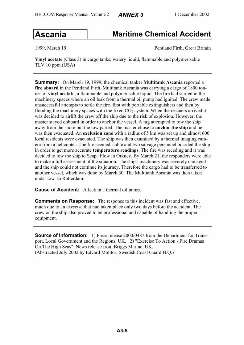
HELCOM Response Manual, Volume 2 ANNEX 3 1 December 2002
A3-5
Ascania Maritime Chemical Accident
1999, March 19 Pentland Firth, Great Britain Vinyl acetate (Class 3) in cargo tanks; watery liquid, flammable and polymerisable TLV 10 ppm (USA) Summary: On March 19, 1999, the chemical tanker Multitank Ascania reported a fire aboard in the Pentland Firth. Multitank Ascania was carrying a cargo of 1800 ton-nes of vinyl acetate, a flammable and polymerisable liquid. The fire had started in the machinery spaces where an oil leak from a thermal oil pump had ignited. The crew made unsuccessful attempts to settle the fire, first with portable extinguishers and then by flooding the machinery spaces with the fixed CO2 system. When the rescuers arrived it was decided to airlift the crew off the ship due to the risk of explosion. However, the master stayed onboard in order to anchor the vessel. A tug attempted to tow the ship away from the shore but the tow parted. The master chose to anchor the ship and he was then evacuated. An exclusion zone with a radius of 5 km was set up and almost 600 local residents were evacuated. The ship was then examined by a thermal imaging cam-era from a helicopter. The fire seemed stable and two salvage personnel boarded the ship in order to get more accurate temperature readings. The fire was receding and it was decided to tow the ship to Scapa Flow in Orkney. By March 21, the responders were able to make a full assessment of the situation. The ship's machinery was severely damaged and the ship could not continue its journey. Therefore the cargo had to be transferred to another vessel, which was done by March 30. The Multitank Ascania was then taken under tow to Rotterdam. Cause of Accident: A leak in a thermal oil pump. Comments on Response: The response to this incident was fast and effective, much due to an exercise that had taken place only two days before the accident. The crew on the ship also proved to be professional and capable of handling the proper equipment. Source of Information: 1) Press release 2000/0487 from the Department for Trans-port, Local Government and the Regions, UK. 2) "Exercise To Action - Fire Dramas On The High Seas", News release from Briggs Marine, UK. (Abstracted July 2002 by Edvard Molitor, Swedish Coast Guard H.Q.)
HELCOM Response Manual, Volume 2 ANNEX 3 1 December 2002
A3-6
Burgenstein Maritime Chemical Accident
1977, January 10 Port of Bremerhaven, Germany Sodium peroxide (Class 5) in drums; solid that reacts violently with water and organic materials; powerful oxidizer that decomposes by heat to free oxygen and may cause fire and explosion in contact with combustibles Sodium cyanide, potassium cyanide (Class 6) in drums; highly toxic solids that in contact with water, moisture, oxidants, or acids emit the extremely poisonous gas hydro-gen cyanide, TLV 10 ppm (USA), IDLH 50 ppm (USA) Summary: During loading of the German ship Burgenstein, a drum with sodium peroxide was damaged by a fork-lift truck and part of the content was spilled on plastic materials on deck. Water from a rainfall had penetrated the hold and water had reached the drums. A truck wheel spun in the spilled peroxide and the wet plastic. Bright yellow flames flared up. The fire spread rapidly to other spills of peroxide on deck and thereaf-ter to the cargo followed by a violent blaze. A number of longshoremen succeeded to escape on a ladder from the burning hold, but three crew died in the fire. The fire brigade arrived and started the fighting with water and foam. The fire spread to other parts of the cargo. Explosions forced the fire fighters to withdraw temporarily. The fire fighting had to be carried out under great precaution due to the presence of cyanides in the cargo that could emit hydrogen cyanide. The port and a large area around was declared as a safety zone and people in parts of the city were told to keep doors and windows closed. After 5 hours, the fire fighters managed to control the fire and after another 4 hours it was extin-guished. Cause of Accident: Damage of sodium peroxide drums by a fork-lift truck during loading. Spill of peroxide reacted with wet plastic sheets under a spinning truck wheel. The resulting fire could spread rapidly around in the hold to other spills of peroxide. Comments on Response: At the initial fire fighting, the fire brigade used water. This was a serious mistake considering the cargo of 1) sodium peroxide that reacts vigorously with water, and 2) cyanides that emit hydrogen cyanide when wet. Source of Information: "The BURGENSTEIN Case", Waterways and Shipping Directorate North, Special Federal Unit for Marine Pollution Control, Deichstrasse 12, D-2190 Cuxhaven, Germany. (Abstracted by Björn Looström, Swedish Coast Guard H.Q.)

HELCOM Response Manual, Volume 2 ANNEX 3 1 December 2002
A3-7
Cason Maritime Chemical Accident
1987, December 5 Off the coast of northwestern Spain Sodium (Class 4) in drums; Sodium is a metal that floats and reacts violently with water or moisture to produce highly flammable hydrogen which may autoignite during the reaction. Sodium is corrosive to skin and eyes. Summary: On a voyage from Antwerp to Shanghai, the cargo of the Panamanian container ship Cason caught fire. Cason first sent a distress message, and one hour later reported that the fire was out of control and that the ship was being abandoned. During the evacuation, 23 of her 31 crew died. Cason carried several different types of chemicals. But the fire probably started in one of the 11 containers of altogether 1430 drums of 126 tons of sodium. A tug tried to salvage Cason, but adverse weather and the fire on board stopped the operation, and Cason went aground 100 m from the shore. A response team started to unload ortho-cresol and formaldehyde drums. But bad weather stopped this work and caused more of the sodium drums to break and catch fire. Soon, the whole ship was on fire. Sodium drums that had fallen into the water were also burning. The fire could be seen far away at sea. Seven days after the initial fire, it was possible to enter the stranded wreck again. The cargo could successively be recovered from Cason and from the shores. The operation was delayed several times because of the weather and technical difficulties. After three weeks the recovery of dangerous goods was regarded as completed. No ecological damage was observed. Cause of Accident: Fire broke out during adverse weather in a freight container with sodium drums, which probably were inappropriately stowed. Comments on Response: The cargo of sodium made the whole operation very complex and dangerous. The great hazard of sodium made it impossible to carry out efficient response work before all the sodium had disappeared through reaction with water. Adverse weather, however, prevented response work also afterwards. Recovery of dangerous goods stowed under deck was difficult and delayed the operation. As a result of this accident, the opinion was raised that shipped sodium should be better packed and secured. Another result from the work was that the use of trade names is highly inappropriate as it causes identification problems. The international co-operation during the response to this accident proved very positive. This is specially valid for the co-operation and advice received from the Marine Environment Division of IMO and from the group of experts of the special "Task Force" created by EEC. Source of Information: An anonymous and undated report titled "The CASON case, December 1987, Northwest Spain" obtained from EEC. (Abstracted by Björn Looström, Swedish Coast Guard H.Q.)

HELCOM Response Manual, Volume 2 ANNEX 3 1 December 2002
A3-8
Cavtat Maritime Chemical Accident
1974, July 14 The Strait of Otranto, off the coast of southern Italy Tetraethyl lead and tetramethyl lead (Class 6) in drums; liquids that are poisonous if inhaled or if skin is exposed; VP 0.01 kPa (20oC), TLV 0.075 mg/m3 (USA), IDLH 40 mg/m3 (USA); marine pollutants Summary: The Yugoslavian dry cargo ship Cavtat collided with the Panamanian bulk carrier Lady Rita. Cavtat, who sank in Italian territorial waters at the depth of 94 m four hours after the collision, carried 150 tons of tetramethyl lead (TML) in 500 drums on deck and 120 tons of tetraethyl led (TEL) in 400 drums in the holds. The hull of Cavtat was split open at the collision and this made salvage of the whole vessel impossi-ble. 400 drums of TML lay on the seabed around the vessel whereas the other drums remained on and within the damaged ship. Some drums became demolished at the acci-dent. After more than two years of governmental discussions and media debate, the Italian Parliament granted financial support for salvage of the cargo. In April 1977 sal-vage of the drums started by the Italian offshore company Saipem. Teams of two satura-tion divers each performed the work inhaling a mixture of oxygen and helium. They worked 8 hours per day during 20 days, after which a three days decompression they were replaced by two new divers. The team spent 16 hours overnight in a residence pressure chamber on a salvage vessel's deck. In the mornings they crept over to a smaller chamber that was descended to a place close to the wreck where they took on outer protecting suits which were kept on the seabed. Through instructions over radio between the salvage vessel and the divers the drums were moved by a lifting device to a special container that could hold 14 drums. When this container had been filled, it was tightened gas-proof, lifted to the vessel and replaced by an empty container. The work was finalized after one year. 93% (250 tons) of the cargo was salvaged and 20 tons lost. Monitoring afterwards showed minor environmental effects. The cost of the operation was USD 16 million. Cause of Accident: The northbound Cavtat suddenly sheered aport and the collision occurred with the southbound Lady Rita. Comments on Response: The decision to salvage the cargo was very much de-layed and was not taken until 2.5 years after the accident, after great pressure from scien-tists, politicians and mass media. When the work started it was performed in a pro-fessional way by an offshore company. Source of Information: 1) Principally personal communication, 2) G. Tiravanti, G. Boari, 1979, "Potential Pollution of a Marine Environment by Lead Alkyls: The Cavtat Incident", Environmental Science & Technology, 13 No. 7, 849-854. (Abstracted by Björn Looström, Swedish Coast Guard H.Q.)
HELCOM Response Manual, Volume 2 ANNEX 3 1 December 2002
A3-9
Dinoseb 1 Maritime Chemical Accident
1984, January 13 North Sea, 150 n.m. east of Esbjerg, Denmark Dinitrobutylphenol (DNBP, Dinoseb) (Class 6) in drums; extremely toxic solid pesti-cide; marine pollutant Summary: The Danish container ship Dana Optima encountered a heavy storm in the North Sea on her way from North Shields in UK to Esbjerg in Denmark. On Friday 13, her main and auxiliary engines stopped which caused some of the deck cargo to fall overboard. One of the lost containers carried 80 drums (200 litres each) of the extremely toxic pesticide dinitrobutylphenol (also known as DNBP or Dinoseb). These drums sank to bottom at the depth of 40 m. An extensive search started by vessels from Denmark and Holland equipped with ordinary sonars, sides can sonars, precision navigation equipment and a remotely operated vehicle (ROV). Dutch trawlers found and recov-ered 13 drums during March 27-30. After a search grid had been established, a system-atic search could start where different sides can sonars were used. A Dutch minehunter made the first finds of 40 drums on April 2. Danish vessels thereafter made further finds and performed also the final salvage. The salvage operation was carried out by divers under surveillance by laboratory personnel. Recovered drum were placed in overpacks and transported to a disposal plant. After 4 months, 72 of the lost 80 drums had been found and salvaged. The drums had been damaged by fishing and salvage gear as well as by the high water pressure. Yet, no environmental effects were observed, due to little pollution by the low-soluble Dinoseb. The cost of the operation for Denmark was 1 million USD. Cause of Accident: Engine failure in heavy storm that caused the ship to list and deck cargo to fall overboard. Comments on Response: Valuable experiences were gained from this case and a strategy was elaborated for such operations. A rough survey was first made by sector-scanning sonars of the types used by fishing vessels and mine hunters. "Hot" areas were then thoroughly searched by means of sides can sonars. After mapping these areas, all suspected items were identified and examined by a submersible (e.g. a ROV) equipped with a TV camera before salvage. Navigation and positioning must be carried out by means of a precision navigation system that has the required accuracy. In this operation a system called ARGO system showed best accuracy, while PULSE/8 was preferred because of greater sturdiness. Source of Information: 1) IMO document MEPC 21/INF.2, Loss and Salvage of Drums Containing DINOSEB, Submitted by Denmark. 2) "Dana Optima", a report on the incident (written in Danish), Submitted by the National Agency of Environmental Protection, Denmark. (Abstracted April 1991 by Björn Looström, Swedish Coast Guard H.Q.)
HELCOM Response Manual, Volume 2 ANNEX 3 1 December 2002
A3-10
Dinoseb 2 Maritime Chemical Accident 1974, July 24 Allentown, Pennsylvania, USA Dinitrobutylphenol (DNBP, Dinoseb) (Class 6) extremely toxic pesticide; marine pollutant Summary: On July 24, 1974, there was a heavy rainfall in Allentown, Pennsylvania. Shortly thereafter the fish started dying in a lake which was a tributary to a public water supply. On August 9 the incident was reported to the authorities. It was found out that a parking lot close to the lake had been treated with the herbicide dinitrobutylphenol (also known as DNBP or Dinoseb) on July 21. This herbicide is extremely toxic and approved for use only in dilute amounts. However, the parking lot had been treated with undiluted product and held very high levels of the herbicide. The outlet from the lake was closed and different options discussed. According to the manufacturer the product would be persistent for at least nine months. By that time it might have contaminated both sur-rounding waters and the groundwater. It was therefore decided that the lake and the parking lot must be decontaminated. This was done with the help of a new mobile haz-ardous spills treatment trailer. This trailer was equipped with a self-contained water treatment system using activated carbon adsorption. The trailer arrived on August 12 and the treatment was started. The intake was placed right by the head of the lake where the highest concentrations of DNBP were found. At first the effluent was put back into the lake as the efficiency of the system was uncertain. Analytical data soon showed that the system was working properly and the effluent was therefore released downstream from the lake. Most of the gravel on the parking lot was removed and sent to a secure site. The parking lot was then hosed with water and the outflow was collected in a sump which had been dug for this purpose. The water in the sump was then treated in the trailer system. The lake and the parking lot were declared as decontaminated by August 22. Cause of Accident: Improper use of an extremely toxic herbicide. Comments on Response: The trailer system proved to be efficient and useful. The problem with this incident was that it took from July 24 to August 9 before anyone contacted the proper authority. This incident clearly shows the importance for people handling dangerous chemicals to be aware of the potential risks. Source of Information: "Removal of spilled herbicide from a New Jersey lake", Article from the 1976 National Conference on Control of Hazardous Material Spills. (Abstracted July 2002 by Edvard Molitor, Swedish Coast Guard H.Q.)
HELCOM Response Manual, Volume 2 ANNEX 3 1 December 2002
A3-11
Finneagle Maritime Chemical Accident
1980, October 1 North Sea, 30 n.m. west of Orkney Islands Trimethyl phosphite (Class 3) in tank container; flammable liquid with high flash point (= low flammability, Class 3.3); reacts violently with acids under production of heat; burns under formation of dangerous phosphorous pentoxide in the smoke gases Summary: On a voyage from New Orleans to Valhamn in Sweden, the Swedish ro-ro ship Finneagle encountered very hard weather that caused shifting of her cargo. A tank container with trimethyl phosphite started to move. It was secured by the crew but came loose again. It was damaged and started to leak. A fire broke out, soon followed by an explosion. The fire increased in ferocity. The sprinkler system was started with light water added and went on for one hour. A distress call was sent out. Finagle’s life boats and liferafts were impossible to launch in the heavy seas. The fire, heat, and irritating and poisonous smoke gases developed to such a degree that the ship had to be aban-doned. Two arriving helicopters were unable to start rescue work because of the weather. A third big helicopter, that arrived later, was able to send down a line and successively save all 22 persons on board, among them one wife and two small children. Still burning, the ship was later towed to Lerwick in the Shetland Islands. On October 4 the main seats of the fire had been extinguished. Cause of Accident: The trimethyl phosphite container on tween deck was unsatis-factorily secured by chains and not placed on deck fittings. Leakage of a rubber solu-tion made the deck slippery which together with the insufficient securing made the arrangement unstable. The trimethyl phosphite container struck repeatedly a refrigerated trailer. Thereby, the tank container was punctured and started to leak. The spill reacted with leaking acid from damaged batteries in the refrigerated trailer. The trimethyl phosphite was heated by the reaction and developed flammable vapours that ignited, probably by sparks from the damaged batteries. Comments on Response: The function of the sprinkler system was unsatisfactory. It sprayed about 300 tons of water until it stopped after one hour due to a pressure failure. Foam or powder is recommended for trimethyl phosphite fire - water is not suitable. The crew worked rationally and efficiently under very difficult conditions. They checked the cargo and improved the lashings. Wearing breathing apparatus they fought the fire in the smoked-filled engine room. The master steered the ship by hand during the whole operation and was able to hold it against wind and sea, thus greatly contributing to the successful abandoning of the ship. The British Search and Rescue Service performed the helicopter rescue very efficiently in darkness and adverse weather. Source of Information: "Fire on Cargo Deck in Swedish Ro-Ro Vessel Finneagle off the Orkneys, October 1, 1980", Marine Accident Report, February 23, 1982, Swedish Maritime Investigation Commission (Abstracted by Björn Looström, Swedish Coast Guard H.Q.)
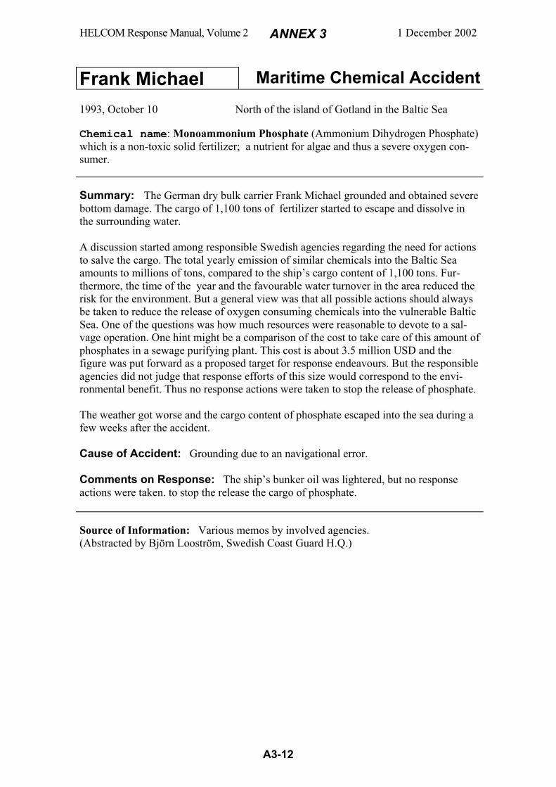
HELCOM Response Manual, Volume 2 ANNEX 3 1 December 2002
A3-12
Frank Michael Maritime Chemical Accident
1993, October 10 North of the island of Gotland in the Baltic Sea Chemical name: Monoammonium Phosphate (Ammonium Dihydrogen Phosphate) which is a non-toxic solid fertilizer; a nutrient for algae and thus a severe oxygen con-sumer.
Summary: The German dry bulk carrier Frank Michael grounded and obtained severe bottom damage. The cargo of 1,100 tons of fertilizer started to escape and dissolve in the surrounding water. A discussion started among responsible Swedish agencies regarding the need for actions to salve the cargo. The total yearly emission of similar chemicals into the Baltic Sea amounts to millions of tons, compared to the ship’s cargo content of 1,100 tons. Fur-thermore, the time of the year and the favourable water turnover in the area reduced the risk for the environment. But a general view was that all possible actions should always be taken to reduce the release of oxygen consuming chemicals into the vulnerable Baltic Sea. One of the questions was how much resources were reasonable to devote to a sal-vage operation. One hint might be a comparison of the cost to take care of this amount of phosphates in a sewage purifying plant. This cost is about 3.5 million USD and the figure was put forward as a proposed target for response endeavours. But the responsible agencies did not judge that response efforts of this size would correspond to the envi-ronmental benefit. Thus no response actions were taken to stop the release of phosphate. The weather got worse and the cargo content of phosphate escaped into the sea during a few weeks after the accident. Cause of Accident: Grounding due to an navigational error. Comments on Response: The ship’s bunker oil was lightered, but no response actions were taken. to stop the release the cargo of phosphate. Source of Information: Various memos by involved agencies. (Abstracted by Björn Looström, Swedish Coast Guard H.Q.)
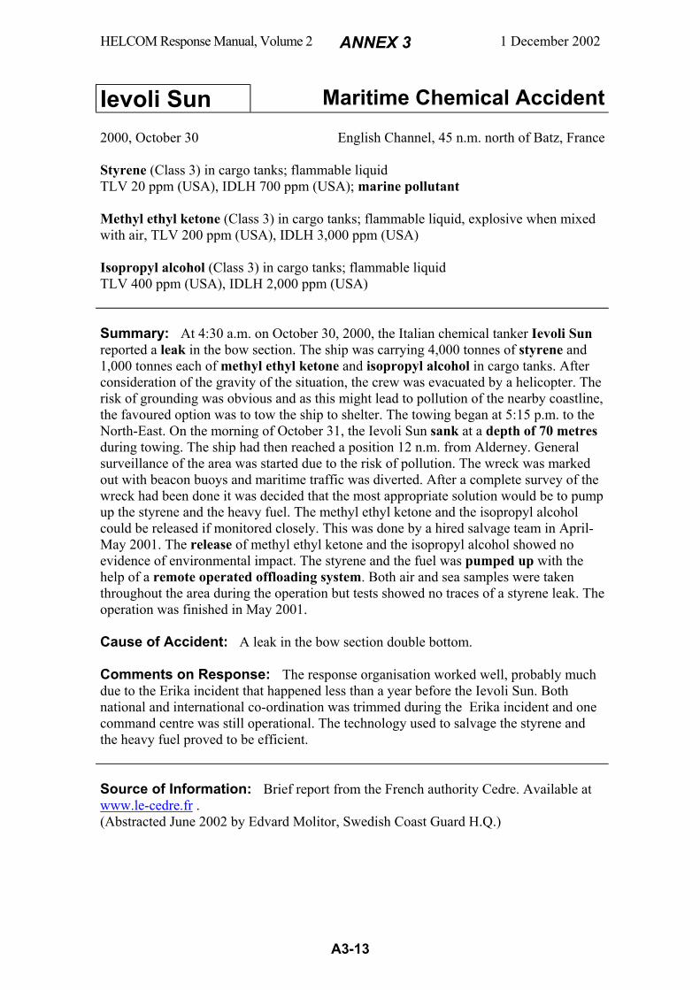
HELCOM Response Manual, Volume 2 ANNEX 3 1 December 2002
A3-13
Ievoli Sun Maritime Chemical Accident
2000, October 30 English Channel, 45 n.m. north of Batz, France Styrene (Class 3) in cargo tanks; flammable liquid TLV 20 ppm (USA), IDLH 700 ppm (USA); marine pollutant Methyl ethyl ketone (Class 3) in cargo tanks; flammable liquid, explosive when mixed with air, TLV 200 ppm (USA), IDLH 3,000 ppm (USA) Isopropyl alcohol (Class 3) in cargo tanks; flammable liquid TLV 400 ppm (USA), IDLH 2,000 ppm (USA) Summary: At 4:30 a.m. on October 30, 2000, the Italian chemical tanker Ievoli Sun reported a leak in the bow section. The ship was carrying 4,000 tonnes of styrene and 1,000 tonnes each of methyl ethyl ketone and isopropyl alcohol in cargo tanks. After consideration of the gravity of the situation, the crew was evacuated by a helicopter. The risk of grounding was obvious and as this might lead to pollution of the nearby coastline, the favoured option was to tow the ship to shelter. The towing began at 5:15 p.m. to the North-East. On the morning of October 31, the Ievoli Sun sank at a depth of 70 metres during towing. The ship had then reached a position 12 n.m. from Alderney. General surveillance of the area was started due to the risk of pollution. The wreck was marked out with beacon buoys and maritime traffic was diverted. After a complete survey of the wreck had been done it was decided that the most appropriate solution would be to pump up the styrene and the heavy fuel. The methyl ethyl ketone and the isopropyl alcohol could be released if monitored closely. This was done by a hired salvage team in April-May 2001. The release of methyl ethyl ketone and the isopropyl alcohol showed no evidence of environmental impact. The styrene and the fuel was pumped up with the help of a remote operated offloading system. Both air and sea samples were taken throughout the area during the operation but tests showed no traces of a styrene leak. The operation was finished in May 2001. Cause of Accident: A leak in the bow section double bottom. Comments on Response: The response organisation worked well, probably much due to the Erika incident that happened less than a year before the Ievoli Sun. Both national and international co-ordination was trimmed during the Erika incident and one command centre was still operational. The technology used to salvage the styrene and the heavy fuel proved to be efficient. Source of Information: Brief report from the French authority Cedre. Available at www.le-cedre.fr . (Abstracted June 2002 by Edvard Molitor, Swedish Coast Guard H.Q.)
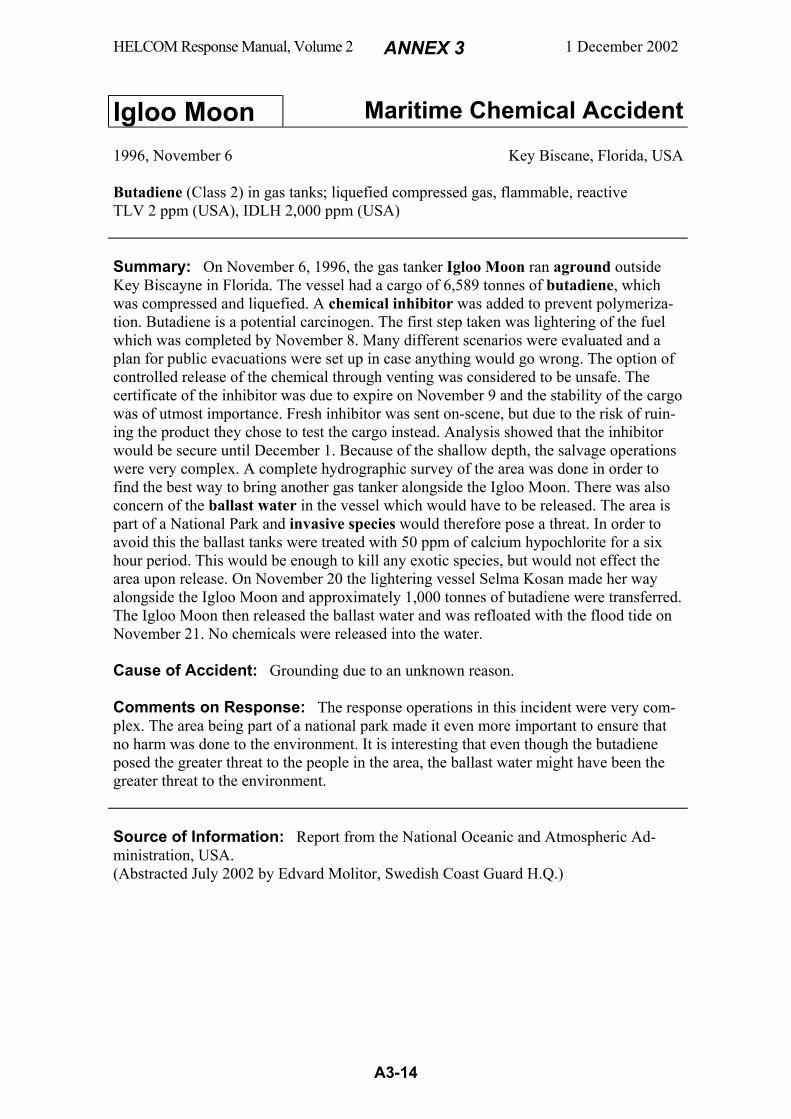
HELCOM Response Manual, Volume 2 ANNEX 3 1 December 2002
A3-14
Igloo Moon Maritime Chemical Accident 1996, November 6 Key Biscane, Florida, USA
Butadiene (Class 2) in gas tanks; liquefied compressed gas, flammable, reactive TLV 2 ppm (USA), IDLH 2,000 ppm (USA) Summary: On November 6, 1996, the gas tanker Igloo Moon ran aground outside Key Biscayne in Florida. The vessel had a cargo of 6,589 tonnes of butadiene, which was compressed and liquefied. A chemical inhibitor was added to prevent polymeriza-tion. Butadiene is a potential carcinogen. The first step taken was lightering of the fuel which was completed by November 8. Many different scenarios were evaluated and a plan for public evacuations were set up in case anything would go wrong. The option of controlled release of the chemical through venting was considered to be unsafe. The certificate of the inhibitor was due to expire on November 9 and the stability of the cargo was of utmost importance. Fresh inhibitor was sent on-scene, but due to the risk of ruin-ing the product they chose to test the cargo instead. Analysis showed that the inhibitor would be secure until December 1. Because of the shallow depth, the salvage operations were very complex. A complete hydrographic survey of the area was done in order to find the best way to bring another gas tanker alongside the Igloo Moon. There was also concern of the ballast water in the vessel which would have to be released. The area is part of a National Park and invasive species would therefore pose a threat. In order to avoid this the ballast tanks were treated with 50 ppm of calcium hypochlorite for a six hour period. This would be enough to kill any exotic species, but would not effect the area upon release. On November 20 the lightering vessel Selma Kosan made her way alongside the Igloo Moon and approximately 1,000 tonnes of butadiene were transferred. The Igloo Moon then released the ballast water and was refloated with the flood tide on November 21. No chemicals were released into the water. Cause of Accident: Grounding due to an unknown reason. Comments on Response: The response operations in this incident were very com-plex. The area being part of a national park made it even more important to ensure that no harm was done to the environment. It is interesting that even though the butadiene posed the greater threat to the people in the area, the ballast water might have been the greater threat to the environment. Source of Information: Report from the National Oceanic and Atmospheric Ad-ministration, USA. (Abstracted July 2002 by Edvard Molitor, Swedish Coast Guard H.Q.)

HELCOM Response Manual, Volume 2 ANNEX 3 1 December 2002
A3-15
Julie A Maritime Chemical Accident
1989, November 4 Harbour of Århus, Denmark Hydrochloric acid (Class 8) in cylindrical tanks; watery liquid, corrosive, reacts with sheet-iron forming flammable hydrogen gas IDLH 50 ppm (USA) Summary: On November 4, 1989, the dry cargo ship Julie A reported a leaking tank of hydrochloric acid on board. The ship was at this time moored in the harbour of Århus. The leaking tank was one out of three cylindrical tanks stored in a hold below deck. The leaking tank contained a total of 300 tonnes of 33% hydrochloric acid, which is very corrosive. When hydrochloric acid reacts with sheet-iron, flammable hydrogen gas is formed. The engines of the ship were therefore shut down. When the responders entered the ship they had to wade through knee-deep hydrochloric acid and they had a visibility of only two metres. They found a 25 mm hole in the tank and they plugged this with a wooden wedge. The acid had eaten its way through the tank as the tank-coating was not strong enough. The acid on the floor had also spread into the ballast tank and threatened to reach through the bottom of the ship. After some trouble finding the appropriate equipment to pump the acid into tanks on-shore, the offloading of acid was initiated. However, quite soon the stability of the ship was decreased and it was therefore decided to move the ship to a dry dock. This was done the next day and after that the ship was dried from the acid through a drilled hole in the bottom of the ship. It was estimated that the total amount of hydrochloric acid spilled in the harbour was about 1-5 tonnes. Cause of Accident: Inappropriate tank coating made of glass-fibre reinforced poly-ester which was corroded by the hydrochloric acid. Comments on Response: Although the responders had trouble finding the right equipment, the operation can be considered a success. This incident shows how impor-tant it is to have knowledge of the chemicals transported. It is also extremely important to have the right kind of transporting equipment. Source of Information: 1) Report 107/89 from "Stadsingeniørens kontor" in Århus. 2) An article from Brandværn 2'90 by Knud Aage Eriksen. (Abstracted July 2002 by Edvard Molitor, Swedish Coast Guard H.Q.)

HELCOM Response Manual, Volume 2 ANNEX 3 1 December 2002
A3-16
Korsnäs Link Maritime Chemical Accident
1991, November 5 Off the English coast, 10 n.m. east of Teeside, England Sodium chlorate (Class 5) in a total of 40 one-tonne bags; solid powerful oxidiser that decomposes by heat to free oxygen and may cause fire and explosion in contact with combustibles Summary: The Swedish ro-ro ferry Stora Korsnäs Link I was on a voyage from Sweden to Hartlepool in England when a fire started in the machine room. Attempts were made to extinguish the fire by filling the machine room with CO2, but the attempts failed and the crew was forced to shut down the engines. The ship’s crew alerted the authorities of the nearest port Teeside and requested help. Rescue vessels were sent to the scene and rescue personnel boarded the ship. Two tugs from a local salvage company arrived and towed the vessel further out to sea. The fire had now spread to the upper deck and the rescue personnel were unable to settle the fire. Eight hours later, the salvage company had contacted the owner of the cargo and found out that the ship did not only carry different forest products but also potentially explosive chemicals. On the lower deck 40 tonnes of sodium chlorate was stowed within two containers. When this was found out the ship was quickly abandoned. A one-mile exclusion zone was established and the salvage tugs left the scene. After sometime they decided however to make a new attempt to save the cargo and a vessel with firefighting equipment was sent to the scene. The started to pump water onto the exterior of the ship in order to achieve control of the fire. The attempt was unsuccessful and the fire spread to the other cargo decks during the following days. On November 8, an explosion occurred close to the containers with sodium chlorate and it blew out the side of the ship causing the ship to roll over and capsize. After a few hours the ship sank at a depth of 40 metres. The explosion caused no injuries but blew out two windows on the firefighting vessel. Cause of Accident: A fire in the machine room which spread to the cargo decks. Comments on Response: The cargo manifest did not have the proper information and this led to a very dangerous situation as the rescue personnel boarded the vessel and tried to fight the fire unaware of the explosion risqué. The second attempt to settle the fire was very risky and it was fortunate that no one got injured. Source of Information: 1) “Gap in the paper chain”, Hazardous Cargo Bulletin, January 1992. 2) Report S 1992:5, Swedish Board of Accident Investigation. (Abstracted July 2001 by Edvard Molitor, Swedish Coast Guard HQ)
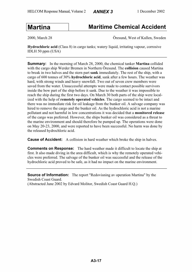
HELCOM Response Manual, Volume 2 ANNEX 3 1 December 2002
A3-17
Martina Maritime Chemical Accident
2000, March 28 Öresund, West of Kullen, Sweden Hydrochloric acid (Class 8) in cargo tanks; watery liquid, irritating vapour, corrosive IDLH 50 ppm (USA) Summary: In the morning of March 28, 2000, the chemical tanker Martina collided with the cargo ship Werder Bremen in Northern Öresund. The collision caused Martina to break in two halves and the stern part sank immediately. The rest of the ship, with a cargo of 600 tonnes of 30% hydrochloric acid, sank after a few hours. The weather was hard, with strong winds and heavy snowfall. Two out of seven crew members were saved from the water. Unsuccessful attempts were made to contact possible survivors inside the bow part of the ship before it sank. Due to the weather it was impossible to reach the ship during the first two days. On March 30 both parts of the ship were local-ized with the help of remotely operated vehicles. The cargo seemed to be intact and there was no immediate risk for oil leakage from the bunker oil. A salvage company was hired to remove the cargo and the bunker oil. As the hydrochloric acid is not a marine pollutant and not harmful in low concentrations it was decided that a monitored release of the cargo was preferred. However, the ships bunker oil was considered as a threat to the marine environment and should therefore be pumped up. The operations were done on May 20-23, 2000, and were reported to have been successful. No harm was done by the released hydrochloric acid. Cause of Accident: A collision in hard weather which broke the ship in halves. Comments on Response: The hard weather made it difficult to locate the ship at first. It also made diving in the area difficult, which is why the remotely operated vehi-cles were preferred. The salvage of the bunker oil was successful and the release of the hydrochloric acid proved to be safe, as it had no impact on the marine environment. Source of Information: The report "Redovisning av operation Martina" by the Swedish Coast Guard. (Abstracted June 2002 by Edvard Molitor, Swedish Coast Guard H.Q.)
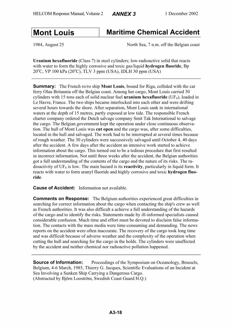
HELCOM Response Manual, Volume 2 ANNEX 3 1 December 2002
A3-18
Mont Louis Maritime Chemical Accident
1984, August 25 North Sea, 7 n.m. off the Belgian coast
Uranium hexafluoride (Class 7) in steel cylinders; low-radioactive solid that reacts with water to form the highly corrosive and toxic gas/liquid hydrogen fluoride, Bp 20oC, VP 100 kPa (20oC), TLV 3 ppm (USA), IDLH 30 ppm (USA)
Summary: The French ro/ro ship Mont Louis, bound for Riga, collided with the car ferry Olau Britannia off the Belgian coast. Among her cargo, Mont Louis carried 30 cylinders with 15 tons each of solid nuclear fuel uranium hexafluoride (UF6), loaded in Le Havre, France. The two ships became interlocked into each other and were drifting several hours towards the shore. After separation, Mont Louis sank in international waters at the depth of 15 metres, partly exposed at low tide. The responsible French charter company ordered the Dutch salvage company Smit Tak International to salvage the cargo. The Belgian government kept the operation under close continuous observa-tion. The hull of Mont Louis was cut open and the cargo was, after some difficulties, located in the hull and salvaged. The work had to be interrupted at several times because of rough weather. The 30 cylinders were successively salvaged until October 4, 40 days after the accident. A few days after the accident an intensive work started to achieve information about the cargo. This turned out to be a tedious procedure that first resulted in incorrect information. Not until three weeks after the accident, the Belgian authorities got a full understanding of the contents of the cargo and the nature of its risks. The ra-dioactivity of UF6 is low. The main hazard is its reactivity, particularly in liquid form. It reacts with water to form uranyl fluoride and highly corrosive and toxic hydrogen fluo-ride. Cause of Accident: Information not available. Comments on Response: The Belgium authorities experienced great difficulties in searching for correct information about the cargo when contacting the ship's crew as well as French authorities. It was also difficult a achieve a full understanding of the hazards of the cargo and to identify the risks. Statements made by ill-informed specialists caused considerable confusion. Much time and effort must be devoted to disclaim false informa-tion. The contacts with the mass media were time-consuming and demanding. The news reports on the accident were often inaccurate. The recovery of the cargo took long time and was difficult because of adverse weather and the complexity of the operation when cutting the hull and searching for the cargo in the holds. The cylinders were unaffected by the accident and neither chemical nor radioactive pollution happened. Source of Information: Proceedings of the Symposium on Oceanology, Brussels, Belgium, 4-6 March, 1985, Thierry G. Jacques, Scientific Evaluations of an Incident at Sea Involving a Sunken Ship Carrying a Dangerous Cargo. (Abstracted by Björn Looström, Swedish Coast Guard H.Q.)

HELCOM Response Manual, Volume 2 ANNEX 3 1 December 2002
A3-19
Oostzee Maritime Chemical Accident
1989, July 18 German Bight Epichlorohydrin (Class 6) in drums; poisonous liquid that emits toxic vapours; VP 2 kPa (20EC), TLV 5 ppm (USA); potential human carcinogen Summary: The Dutch cargo ship Oostzee ran into a storm en route from Rotterdam to Leningrad. 975 tons of epichlorohydrin in 3900 drums (250 kg per drum) was stowed in upright position, without proper lashings, on the smooth-surfaced tweendeck. Filled drums, stowed around empty drums, shifted in the storm and squeezed the empty ones, thus resulting in greater shift and damage. Leaking drums gave rise to dangerous at-mosphere that caused inhalation poisoning among the crew. Oostzee was instructed by the German Shipping Administration to anchor at a place close to Cuxhaven. All 14 crew were hospitalised for 10 days. The cargo holds were found to contain highly toxic atmosphere and a great number of damaged and leaking drums mixed with general cargo. As a first step, part of the spilled epichlorohydrin was pumped up and transported to a disposal site. The ship was taken to a better equipped port in the River Elbe but was soon moved to a less populated port in the Elbe Estuary. Special care was first taken to reduce the risk of explosion. But later it was realised that the gas concentrations were far below the flammable limit (but yet highly toxic). The engine rooms and the cargo holds were ventilated with the object to reduce the concentration of epichlorohydrin vapours to 3 ppm. During this work a wide safety zone was established around the vessel (diameter 1000 m) as well as in the airspace above (height 2000 ft). Damaged drums were transferred to overpacks and transported to a chemical company for dis-posal. Also the general cargo was finally unloaded. 263 damaged drums and 2200 l of epichlorohydrin had been taken care of for disposal. 8100 l of epichlorohydrin had evaporated into the air during the operation. Cause of accident: See above. Shifting of cargo in adverse weather owing to im-proper stowage. Comments on response: In the beginning of the operation it was difficult to assess the hazard from the cargo and Oostzee had for safety reasons to be moved several times during the response operation. There were no tugboats available that had safety equip-ment for toxic gases. The epichlorohydrin vapours were found to be more dangerous than expected and 30 persons from the response organisation and mass media had to be medically examined. One person was irreversibly injured. In view of these incidents, the awareness and cautiousness regarding the toxic and carcinogenic properties of epichloro-hydrin might be questioned. Source of information: "The OOSTZEE Case July/August 1989", Waterways and Shipping Directorate North, Special Federal Unit for Marine Pollution Control, Deich-strasse 12, D-2190 Cuxhaven, Germany. (Abstracted by Björn Looström, Swedish Coast Guard H.Q.)
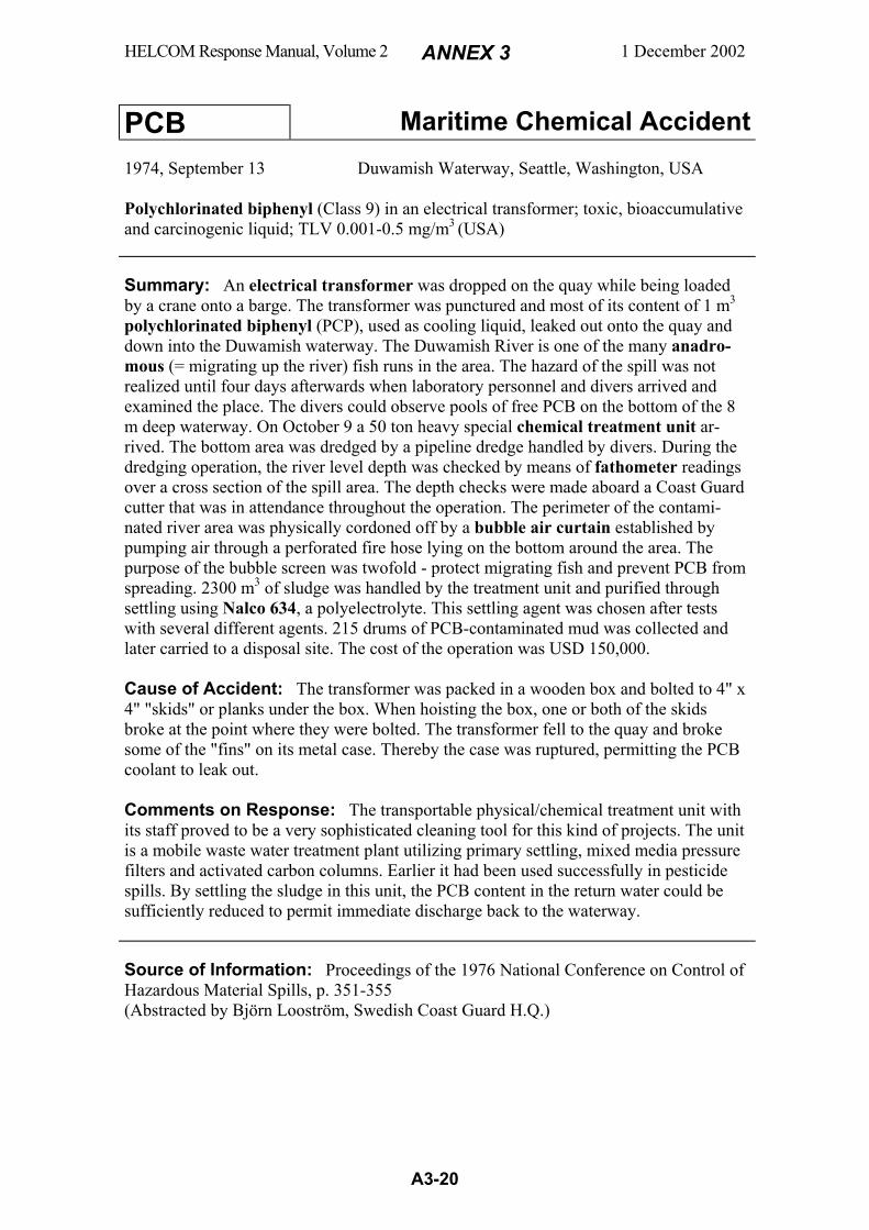
HELCOM Response Manual, Volume 2 ANNEX 3 1 December 2002
A3-20
PCB Maritime Chemical Accident
1974, September 13 Duwamish Waterway, Seattle, Washington, USA Polychlorinated biphenyl (Class 9) in an electrical transformer; toxic, bioaccumulative and carcinogenic liquid; TLV 0.001-0.5 mg/m3 (USA) Summary: An electrical transformer was dropped on the quay while being loaded by a crane onto a barge. The transformer was punctured and most of its content of 1 m3
polychlorinated biphenyl (PCP), used as cooling liquid, leaked out onto the quay and down into the Duwamish waterway. The Duwamish River is one of the many anadro-mous (= migrating up the river) fish runs in the area. The hazard of the spill was not realized until four days afterwards when laboratory personnel and divers arrived and examined the place. The divers could observe pools of free PCB on the bottom of the 8 m deep waterway. On October 9 a 50 ton heavy special chemical treatment unit ar-rived. The bottom area was dredged by a pipeline dredge handled by divers. During the dredging operation, the river level depth was checked by means of fathometer readings over a cross section of the spill area. The depth checks were made aboard a Coast Guard cutter that was in attendance throughout the operation. The perimeter of the contami-nated river area was physically cordoned off by a bubble air curtain established by pumping air through a perforated fire hose lying on the bottom around the area. The purpose of the bubble screen was twofold - protect migrating fish and prevent PCB from spreading. 2300 m3 of sludge was handled by the treatment unit and purified through settling using Nalco 634, a polyelectrolyte. This settling agent was chosen after tests with several different agents. 215 drums of PCB-contaminated mud was collected and later carried to a disposal site. The cost of the operation was USD 150,000. Cause of Accident: The transformer was packed in a wooden box and bolted to 4" x 4" "skids" or planks under the box. When hoisting the box, one or both of the skids broke at the point where they were bolted. The transformer fell to the quay and broke some of the "fins" on its metal case. Thereby the case was ruptured, permitting the PCB coolant to leak out. Comments on Response: The transportable physical/chemical treatment unit with its staff proved to be a very sophisticated cleaning tool for this kind of projects. The unit is a mobile waste water treatment plant utilizing primary settling, mixed media pressure filters and activated carbon columns. Earlier it had been used successfully in pesticide spills. By settling the sludge in this unit, the PCB content in the return water could be sufficiently reduced to permit immediate discharge back to the waterway. Source of Information: Proceedings of the 1976 National Conference on Control of Hazardous Material Spills, p. 351-355 (Abstracted by Björn Looström, Swedish Coast Guard H.Q.)
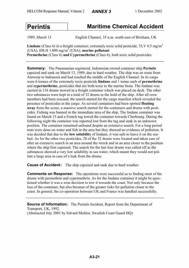
HELCOM Response Manual, Volume 2 ANNEX 3 1 December 2002
A3-21
Perintis Maritime Chemical Accident
1989, March 13 English Channel, 35 n.m. south-east of Brixham, UK Lindane (Class 6) in a freight container; extremely toxic solid pesticide, TLV 0.5 mg/m3 (USA), IDLH 1.000 mg/m3 (USA); marine pollutant Permethrine (Class 6) and Cypermethrine (Class 6), both toxic solid pesticides Summary: The Panamanian registered, Indonesian owned container ship Perintis capsized and sank on March 13, 1989, due to hard weather. The ship was en route from Antwerp to Indonesia and had reached the middle of the English Channel. In its cargo were 6 tonnes of the extremely toxic pesticide lindane and 1 tonne each of permethrine and cypermethrine, pesticides that are both toxic to the marine biota. The lindane was carried in 116 drums stowed in a freight container which was placed on deck. The other two substances were kept in a total of 32 drums in the hold of the ship. After all crew members had been rescued, the search started for the cargo manifest which revealed the presence of pesticides in the cargo. As several containers had been spotted floating away from the scene, a massive search started for the containers and drums with pesti-cides. Fishing was banned in the immediate area of the ship. The lindane container was found on March 15 and a French tug towed the container towards Cherbourg. During the following night the container was reported lost from the tug and sunk in an unknown position. The container remained unfound despite an extensive search. For a long period tests were done on water and fish in the area but they showed no evidence of pollution. It was decided that due to the low solubility of lindane, it was safe to leave it on the sea-bed. As for the other two pesticides, 28 of the 32 drums were located and taken care of after an extensive search in an area around the wreck and in an area closer to the position where the ship first capsized. The search for the last four drums was called off as the substances showed a very low solubility in sea water, which meant they would not pol-lute a large area in case of a leak from the drums. Cause of Accident: The ship capsized and sank due to hard weather. Comments on Response: The operations were successful as to finding most of the drums with permethrin and cypermethrin. As for the lindane container it might be ques-tioned whether it was a wise decision to tow it towards the coast. Not only because the loss of the container, but also because of the greater risks for pollution closer to the coast. In general, the co-operation between UK and France was handled successfully. Source of Information: The Perintis Incident, Report from the Department of Transport, UK, 1992. (Abstracted July 2001 by Edvard Molitor, Swedish Coast Guard HQ)
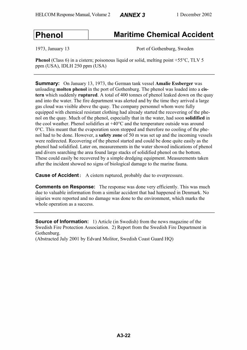
HELCOM Response Manual, Volume 2 ANNEX 3 1 December 2002
A3-22
Phenol Maritime Chemical Accident
1973, January 13 Port of Gothenburg, Sweden Phenol (Class 6) in a cistern; poisonous liquid or solid, melting point +55°C, TLV 5 ppm (USA), IDLH 250 ppm (USA) Summary: On January 13, 1973, the German tank vessel Amalie Essberger was unloading molten phenol in the port of Gothenburg. The phenol was loaded into a cis-tern which suddenly ruptured. A total of 400 tonnes of phenol leaked down on the quay and into the water. The fire department was alerted and by the time they arrived a large gas cloud was visible above the quay. The company personnel whom were fully equipped with chemical resistant clothing had already started the recovering of the phe-nol on the quay. Much of the phenol, especially that in the water, had soon solidified in the cool weather. Phenol solidifies at +40°C and the temperature outside was around 0°C. This meant that the evaporation soon stopped and therefore no cooling of the phe-nol had to be done. However, a safety zone of 50 m was set up and the incoming vessels were redirected. Recovering of the phenol started and could be done quite easily as the phenol had solidified. Later on, measurements in the water showed indications of phenol and divers searching the area found large stacks of solidified phenol on the bottom. These could easily be recovered by a simple dredging equipment. Measurements taken after the incident showed no signs of biological damage to the marine fauna. Cause of Accident: A cistern ruptured, probably due to overpressure. Comments on Response: The response was done very efficiently. This was much due to valuable information from a similar accident that had happened in Denmark. No injuries were reported and no damage was done to the environment, which marks the whole operation as a success. Source of Information: 1) Article (in Swedish) from the news magazine of the Swedish Fire Protection Association. 2) Report from the Swedish Fire Department in Gothenburg. (Abstracted July 2001 by Edvard Molitor, Swedish Coast Guard HQ)
HELCOM Response Manual, Volume 2 ANNEX 3 1 December 2002
A3-23
Poona Maritime Chemical Accident
1971, July 15 Port of Gothenburg, Sweden Sodium chlorate (Class 5) in drums; solid powerful oxidizer that decomposes by heat to free oxygen and may cause fire and explosion in contact with combustibles Summary: The Danish dry cargo vessel Poona of 8000 dwt was loading steel struc-tures in the port of Gothenburg. The hold contained a cargo of, among other things, 36 tons of sodium chlorate in 100 kg drums and 600 tons of rape oil in 200 l drums. All drums of both substances were stowed on pallets in the same holds. Three heavy struc-tures were going to be hoisted by a crane into the hold, one by one. The first structure started to swing and thereby punctured a drum of rape oil so that the content of 100 l ran out. When the last structure was handled, it struck a drum of sodium chlorate with the result that a part of its content came out and mixed with the rape oil. The structure then slid on the floor creating sparks that ignited the mixture. The sodium chlorate was de-composed by the heat to free oxygen, which started a violent fire in the hold. After one or two minutes, flames flared up out of the hold and after another few minutes three severe explosions occurred in rapid succession. They were so violent that hatch covers were thrown away onto the quay and some of them several hundred metres away. The fire fighting operation became very difficult and dangerous due to the ferocity of the fire and also due to the fact that the ship also contained carbides. The latter chemical pre-vented the use of water as fire extinguishing agent. The fire fighting went on for 4 days and had to be performed both from the quay and from the sea side. The work on final extinction of the fire continued for 10 days. Three persons were killed and six injured during the accident. Cause of Accident: See above. It is highly inappropriate and reprehensible to stow oxidizers and combustibles in the same hold. Comments on Response: This fire fighting operation was very complicated and perhaps the most difficult one ever happened in Gothenburg. Source of Information: Brief article (in Swedish) in the news magazine of the Swedish Fire Protection Association. (Abstracted by Björn Looström, Swedish Coast Guard H.Q.)
HELCOM Response Manual, Volume 2 ANNEX 3 1 December 2002
A3-24
Propionic acid Maritime Chemical Accident
1975, January Shores of the Swedish West Coast, about 100 km north of Gothenburg Propionic acid (Class 8) in drums; corrosive liquid that emits irritating and harmful vapours; VP 1.3 kPa (20EC), TLV 10 ppm (USA) Summary: On several occasions around January 8-10, 1975, approximately 30 drums of propionic acid were found on different positions on shores of the Swedish West Coast about 100 km north of Gothenburg. Propionic acid is an organic acid used for fabrication of many different products like preservatives, flavours and perfume bases. Before salvage, the drums were carefully examined by the Coast Guard for any ruptures and leaks. The drums were then very cautiously salvaged from the shores and lifted on board Coast Guard cutters. It was not possible to judge how long time the drums had been moved by the sea and exposed to marine water. However, the drums were very rusty and were lacking labels, placards and inscriptions. After sampling and subsequent chemical analysis in a laboratory, the content was identified as propionic acid. The drums were taken to a temporary store until further transport to a disposal plant. Cause of Accident: Probably lost deck cargo. Comments on Response: Besides ordinary working-clothes, the response person-nel wore only gloves and rubber boots as safety protection garments when salvaging the drums. Being aware of the nature of the chemical (corrosive liquid and fumes), the per-sonnel should have worn full body protection. After salvage from the shore, the drums should immediately have been placed in overpacks. The incident was only recorded very briefly in a log-book. A full detailed report should have been written, with an evaluation of the response operation and notes on the response failures. Source of Information: Swedish Coast Guard log-book notes and short articles in a local newspaper. (Abstracted by Björn Looström, Swedish Coast Guard H.Q.)
HELCOM Response Manual, Volume 2 ANNEX 3 1 December 2002
A3-25
Puerto Rican Maritime Chemical Accident
1984, October 31 Off the coast west of San Francisco, California, USA Caustic soda solution 50% (Class 8) in a cargo tank; corrosive solution that reacts with many metals, e.g. zinc generating hydrogen gas, which is flammable and explosive. Summary: The U.S.-registered chemical tankship Puerto Rican was preparing to disembark a pilot about 8 miles west of the Golden Gate Bridge when an explosion occurred in the vicinity of the vessel's center void space No. 6. The main deck over the void and adjacent wing tanks was lifted up, blown forward and landed inverted over center cargo tank. An intense fire erupted and burned out of control for several hours. At the time of the explosion, the pilot, a third mate and an able seaman were standing on the port side of the main deck. As a result of the explosion, the three men were thrown over the side. The pilot and the third man were seriously injured, but were recovered alive from the water. The able seaman was not found. The remaining 26 people onboard abandoned the ship safely. A few hours after the explosion, the vessel was towed farther offshore in an effort to avoid polluting the coastline if the vessel sank. Several days later the vessel broke in two while in heavy seas, and the stern section sank. The bow section remained afloat and was later towed in to a shipyard. Cause of Accident: The proximate cause of this casualty was the failure to repair a hole through the stainless steel cladding on the bulkhead separating 5 central port (5CP) and 6 center void (6CV). About 400-500 m3 of caustic soda solution leaked through the hole from 5 CP into 6CV, creating a liquid level height of about two feet. The caustic soda reacted with the zinc-rich epoxy coating on the bulkheads, tank supports and deck of 6CV, consuming the zinc and liberat-ing hydrogen gas. Approximately 200 m3 of alkyl benzene in 5CP also leaked into 6CV through the hole. This created a flammable mixture which was ignited shortly before the explosion which inverted the main deck section. The most probable ignition source was a spark within 6CV, either from metal-to-metal contact or an electrostatic discharge. Comments on Response: Contributing to the cause of this casualty was the failure of the captain to use all reasonable means to account for the caustic soda discrepancy from 5CP. Three weeks before the accident Puerto Rican completed loading a 50 percent caustic soda solution, at a terminal in Louisiana. Two weeks later after discharging caustic soda from three tanks in San Pedro, California, a discrepancy was noted in the amount left tank number 5CP, indicating there could be leakage. The captain of the Puerto Rican determined that the discrepancy was due to a recording error. Nevertheless, all double bottom and void spaces around 5CP were sounded, with the exception of 6CV. This space was supposed to be sealed and inerted with nitrogen gas. The adjacent cargo tanks were also checked for leakage of caustic soda from 5CP. No evidence of leakage was found. The captain decided to inspect tank No. 5CP later after the tank had been emptied of cargo and cleaned. Although the presence of caustic soda in space No. 6CV also could have been detected by activating the eductor system, but the crew was not aware that the eductor system existed. Source of Information: Reports by US Coast Guard Marine Board of Investigation and US National Transportation Safety Board. (Abstracted by Björn Looström, Swedish Coast Guard H.Q.)
HELCOM Response Manual, Volume 2 ANNEX 3 1 December 2002
A3-26
René 16 Maritime Chemical Accident
1976, January 16 Port of Landskrona, Sweden Ammonia (Class 2, 8) in tank container; liquefied compressed gas, corrosive, produces poisonous vapour cloud, TLV 25 ppm (USA), IDLH 300 ppm (USA) Summary: In the evening of January 16, 1976, the Belgian tanker René 16 was un-loading ammonia in the port of Landskrona in Sweden. The ammonia was pumped through a rubber hose into a tank on the quay. After a few hours the hose suddenly ruptured with a loud bang. Ammonia started to spurting onto the quay and continued to squirt after the personnel on the quay had closed the valve on the quay side and shut of the compressor. The fire brigade was alerted and arrived within ten minutes. The ammo-nia had by then produced a large cloud that covered the vessel. The firemen sprayed the cloud with water washing it down on board the ship in order to clear the sight. They managed to close the valve on the ship’s side and the ammonia stopped leaking. It had by that time leaked out about 180 tonnes of ammonia onto the quay and a cloud of am-monia had moved by the wind towards a shipyard nearby. Fortunately there was no one there and the cloud dispersed after about an hour. On the quay however two members of the crew were found dead. They had been captured by the cloud resulting in oedema of their lungs. It was later found out that the hose used was intended for propane and butane and not ammonia, which is corrosive. The inside of the hose had been partially de-stroyed by the ammonia and this was the direct cause of the rupture. Cause of Accident: An incorrect choice of hose. Comments on Response: This accident was all due to the misuse of equipment. It shows the danger of using the wrong equipment and stresses the awareness of a chemi-cals properties when handling the chemical. Source of Information: Ammonia Loading Line Rupture, Report from Supra, 1976, Sweden. (Abstracted July 2001 by Edvard Molitor, Swedish Coast Guard HQ)
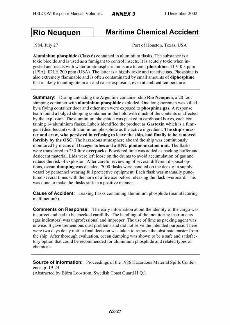
HELCOM Response Manual, Volume 2 ANNEX 3 1 December 2002
A3-27
Rio Neuquen Maritime Chemical Accident
1984, July 27 Port of Houston, Texas, USA Aluminium phosphide (Class 6) contained in aluminium flasks. The substance is a toxic biocide and is used as a fumigant to control insects. It is acutely toxic when in-gested and reacts with water or atmospheric moisture to emit phosphine, TLV 0.3 ppm (USA), IDLH 200 ppm (USA). The latter is a highly toxic and reactive gas. Phosphine is also extremely flammable and is often contaminated by small amounts of diphosphine that is likely to autoignite in air and cause explosion, even at ambient temperature. Summary: During unloading the Argentine container ship Rio Neuquen, a 20 foot shipping container with aluminium phosphide exploded. One longshoreman was killed by a flying container door and other men were exposed to phosphine gas. A response team found a bulged shipping container in the hold with much of the contents unaffected by the explosion. The aluminium phosphide was packed in cardboard boxes, each con-taining 14 aluminium flasks. Labels identified the product as Gastoxin which is a fumi-gant (disinfectant) with aluminium phosphide as the active ingredient. The ship's mas-ter and crew, who persisted in refusing to leave the ship, had finally to be removed forcibly by the OSC. The hazardous atmosphere aboard the ship was continuously monitored by means of Draeger tubes and a HNU photoionization unit. The flasks were transferred to 230-litre overpacks. Powdered lime was added as packing buffer and desiccant material. Lids were left loose on the drums to avoid accumulation of gas and reduce the risk of explosion. After careful reviewing of several different disposal op-tions, ocean dumping was decided. 7000 flasks were handled on the deck of a supply vessel by personnel wearing full protective equipment. Each flask was manually punc-tured several times with the horn of a fire axe before releasing the flask overboard. This was done to make the flasks sink in a positive manner. Cause of Accident: Leaking flasks containing aluminium phosphide (manufacturing malfunction?). Comments on Response: The early information about the identity of the cargo was incorrect and had to be checked carefully. The handling of the monitoring instruments (gas indicators) was unprofessional and improper. The use of lime as packing agent was unwise. It gave tremendous dust problems and did not serve the intended purpose. There were two days delay until a final decision was taken to remove the obstinate master from the ship. After thorough evaluation, ocean dumping was shown to be a safe and satisfac-tory option that could be recommended for aluminium phosphide and related types of chemicals. Source of Information: Proceedings of the 1986 Hazardous Material Spills Confer-ence, p. 19-24. (Abstracted by Björn Looström, Swedish Coast Guard H.Q.).
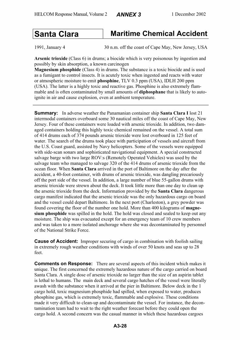
HELCOM Response Manual, Volume 2 ANNEX 3 1 December 2002
A3-28
Santa Clara Maritime Chemical Accident
1991, January 4 30 n.m. off the coast of Cape May, New Jersey, USA
Arsenic trioxide (Class 6) in drums; a biocide which is very poisonous by ingestion and possibly by skin absorption, a known carcinogen Magnesium phosphide (Class 4) in drums. The substance is a toxic biocide and is used as a fumigant to control insects. It is acutely toxic when ingested and reacts with water or atmospheric moisture to emit phosphine, TLV 0.3 ppm (USA), IDLH 200 ppm (USA). The latter is a highly toxic and reactive gas. Phosphine is also extremely flam-mable and is often contaminated by small amounts of diphosphane that is likely to auto-ignite in air and cause explosion, even at ambient temperature. Summary: In adverse weather the Panamanian container ship Santa Clara I lost 21 intermodal containers overboard some 30 nautical miles off the coast of Cape May, New Jersey. Four of these containers were loaded with arsenic trioxide. In addition, two dam-aged containers holding this highly toxic chemical remained on the vessel. A total sum of 414 drums each of 374 pounds arsenic trioxide were lost overboard in 125 feet of water. The search of the drums took place with participation of vessels and aircraft from the U.S. Coast guard, assisted by Navy helicopters. Some of the vessels were equipped with side-scan sonars and sophisticated navigational equipment. A special constructed salvage barge with two large ROV:s (Remotely Operated Vehicles) was used by the salvage team who managed to salvage 320 of the 414 drums of arsenic trioxide from the ocean floor. When Santa Clara arrived in the port of Baltimore on the day after the accident, a 40-foot container, with drums of arsenic trioxide, was dangling precariously off the port side of the vessel. In addition, a large number of blue 55-gallon drums with arsenic trioxide were strewn about the deck. It took little more than one day to clean up the arsenic trioxide from the deck. Information provided by the Santa Clara dangerous cargo manifest indicated that the arsenic trioxide was the only hazardous cargo on board and the vessel could depart Baltimore. In the next port (Charleston), a grey powder was found covering the floor of the number one hold. More than 400 kilograms of magne-sium phosphide was spilled in the hold. The hold was closed and sealed to keep out any moisture. The ship was evacuated except for an emergency team of 10 crew members and was taken to a more isolated anchorage where she was decontaminated by personnel of the National Strike Force. Cause of Accident: Improper securing of cargo in combination with foolish sailing in extremely rough weather conditions with winds of over 50 knots and seas up to 28 feet. Comments on Response: There are several aspects of this incident which makes it unique. The first concerned the extremely hazardous nature of the cargo carried on board Santa Clara. A single dose of arsenic trioxide no larger than the size of an aspirin tablet is lethal to humans. The main deck and several cargo hatches of the vessel were literally awash with the substance when it arrived at the pier in Baltimore. Below deck in the 1 cargo hold, toxic magnesium phosphide had spilled, when exposed to water, produces phosphine gas, which is extremely toxic, flammable and explosive. These conditions made it very difficult to clean-up and decontaminate the vessel. For instance, the decon-tamination team had to wait to the right weather forecast before they could open the cargo hold. A second concern was the casual manner in which these hazardous cargoes
HELCOM Response Manual, Volume 2 ANNEX 3 1 December 2002
A3-29
were treated. The vessel's owner and crew failed to record the drums of magnesium phosphide on the cargo manifest. A crewman scooped up some of the spilled powder in his hands, smelled it, and though he felt sick, never reported it to the ship's medical officer. The crew freely wandered about the deck contaminated with arsenic trioxide, despite the fact that they were warned of the danger. The final and, perhaps the most serious aspect of the Santa Clara incident, was an unwillingness by the owner of the vessel to step forward and call attention to the gravity of the problem. In Baltimore, a cargo surveyor hired by the ship's owner examined the condition of the cargo. He wit-nessed extensive cargo damage and spillage below decks, but no report was filed to the Coast Guard. Therefore, the vessel could leave Baltimore in an extremely hazardous condition, placing its crew and ultimately put the port of Charleston and its citizens at great risk. The Coast Guard recommended criminal action against Santa Clara's owner. Source of Information: Proceedings of the Marine Safety Council, Jan-Feb 1993, Vol. 50, No. 1 (Abstracted by Björn Looström, Swedish Coast Guard H.Q.)

HELCOM Response Manual, Volume 2 ANNEX 3 1 December 2002
A3-30
Sindbad Maritime Chemical Accident
1979, December 10 North Sea, 20 n.m. west of IJmuiden, Holland Chlorine (Class 2) in steel cylinders; corrosive and highly toxic gas TLV 0.5 ppm (USA), IDLH 30 ppm (USA); marine pollutant Summary: In adverse weather, the Iraqi ship Sindbad lost her deck cargo on her way from Hamburg to Rotterdam at a depth of 25-30 metres. Among the cargo, there were 51 steel cylinders (size 0.9x2 m), each filled with 1000 kg liquefied chlorine (Bp. 34oC) that gives pressure of 340 kPa at a bottom water temperature of 5oC. A search started in two 1x18 km areas by two ships equipped with side-scan sonars. In January 1980, 5 cylinders were located. They were attached to steel lines by divers, and recovered. After these finds, the state-organised search had to be suspended, but a premium was offered to fishermen for each cylinder brought ashore. During the following four years, 7 cylin-ders were found and trawled by fishermen. The last cylinders found in this period were very corroded and thereby showed that the cylinders constituted a great hazard to fisher-men and other seafarers. The Dutch authorities elaborated a special response strategy for the situation. In 1984 a new extensive search started with side-scan sonars. Registered bottom echoes were closer inspected by a remotely operated vehicle (ROV) Duplus II. Some of the found cylinders were moored to a safer place on the seafloor. Divers then placed 6 kg of the explosive Donarit S under each cylinder, which then was blasted under control. The chlorine content of each cylinder raised to the surface and developed, in one hour, a cloud 300 m wide, 3000 m long and 300 m high. It was made better visi-ble by releasing ammonia from a ship upwind. The reaction between ammonia and chlorine formed a clearly visible white cloud of ammonium chloride. No ecological damage was detected from chlorine. Single seabirds were occasionally observed flying into the gas cloud and falling immediately like stones to the water surface. The total cost for the Dutch authorities was around $ 1 million. Cause of Accident: Lost deck cargo in adverse weather. Comments on Response: It was a long delay, of almost 5 years until 1984, before the final response operation started. The reason for this is unclear and might be ques-tioned. The strategy with controlled blasting of the cylinders was elaborated after careful studies of different alternatives. It proved to be a successful method as performed in this operation with careful supervision of the spreading of the gas clouds. It was an ingenious method to highlight the chlorine cloud with ammonia. Source of Information: Proceedings of the 1986 Hazardous Material Spills Confer-ence, p. 25-36, and personal communication. (Abstracted by Björn Looström, Swedish Coast Guard H.Q.)

HELCOM Response Manual, Volume 2 ANNEX 3 1 December 2002
A3-31
Stanislaw Dubois Maritime Chemical Accident
1981, April 2 North Sea, off the Dutch island of Texel Calcium carbide (Class 4) in drums; solid that produces the highly flammable gas acetylene on contact with water or moisture Summary: In Gdynia/Gdansk, the Polish general cargo ship Stanislaw Dubois loaded 857 tons of calcium carbide in drums and 955 tons of caustic soda (solid sodium hy-droxide) in bags. Then proceeding to Hamburg she loaded 5.4 tons of a flammable or-ganic peroxide and 5.6 tons of an explosive. With this dangerous goods as well as other cargo she left for South East Asia, via Antwerp. On her way in the North Sea, she col-lided with the Sudanese ship Omdurman off the Dutch island of Texel. Stanislaw Du-bois was struck in her port side creating a hole of 7 x 7 m, one meter above the bilge keel. The holds no. 2 and 3 became immediately flooded. The bulwark, hatch covers, main deck and mast house were also damaged. Tugs arrived and towed the ship towards Rotterdam with the intention to be repaired. The flooded hold contained 500 tons of calcium carbide and 400 tons of cellulose. The latter cargo had swollen up by the water. Thereby, it had pressed on the cargo of calcium carbide, which was contained in drums with removable heads. This caused drum heads to open and water could penetrate to the calcium carbide. As there was a risk of explosion, the ship was not allowed to enter neither any Dutch port, nor any other port in the EEC countries. On the other hand, the vessel's draught increased by the water flooding to 45 feet, which made it impossible to enter any port in Europe. After 7 days of negotiations, Dutch authorities ordered Stanislaw Dubois to be sunk. Salvage vessels kept her afloat through continuous pump-ing and lightered all her fuel oil. Finally, the Dutch Navy frigate Callenburgh escorted Stanislaw Dubois to a position 90 n.m. NW of the island of Texel. There she was sunk (scuttled) at a depth of 72 m on April 9, 1981. Cause of Accident: Flooding of holds through a hole in the port side, which was created by a collision. The water penetrated to a cargo of calcium carbide, which caused an imminent risk of explosion. The water flooding of the ship, caused her draught to increase to such an extent that it was impossible for her to enter any port for repair. Comments on Response: The drastic response option to sink the ship, was perhaps the only alternative in view of the low possibility to enter any harbour for repair. Source of Information: Brief report prepared in 1991 by the Polish Ocean Lines, Gdynia, Poland. (Abstracted by Björn Looström, Swedish Coast Guard H.Q.)

HELCOM Response Manual, Volume 2 ANNEX 3 1 December 2002
A3-32
Styrene Barge Maritime Chemical Accident
1992, January 26 Wax Lake Spillway, Louisiana, USA Styrene (Class 3) in cargo tanks; flammable liquid, produces irritating vapour, may polymerize if contaminated or subjected to heat TLV 20 ppm (USA), IDLH 700 ppm (USA); marine pollutant Summary: On January 26, 1992, two barges collided on the Intracoastal waterway close to Wax Lake in Louisiana. One of the barges was in tow by the tug De Lasalle and the other by the tug Scaup. The barge towed by De Lasalle carried a cargo tank with 340,000 litres of styrene. The collision caused a breach in the tank and styrene started leaking. The barge was released from the tug and dropped below the water level, caus-ing more styrene to leak out. The styrene spread very quickly and within minutes it had begun moving downcurrent. The waterway was closed a few kilometers from the spill and booms were deployed to stop the spreading of styrene. As styrene is a clear and colourless liquid it was only the strong odour that showed where it was spreading. Later however it was found out that the styrene was easily monitored with the help of for-ward-looking infrared imager (FLIR). The styrene reached the soil on the south em-bankment and contaminated it. Some of it also polymerized and formed clumps with silt and other solids, causing it to sink. Later on this sunken polymer was washed ashore by waves. It was first attempted to pick up the styrene with the help of a belt skimmer with an oleophilic belt. However, the belt was dissolved by the styrene and it was found out that in order to use the belt it was necessary to first put peat moss on the styrene. The main part was therefore done with mechanical pickup by vacuum trucks mounted on barges. The operations lasted for almost a month and were finished by the end of Febru-ary. Cause of Accident: A collision between two barges, each in tow by a tug. Comments on Response: The response towards this incident was late and not effective enough. It took three days to establish an area monitoring plan and by this time much of the spill had already sunk into the shoreline. The use of oleophilic belts on the belt skimmer is of coarse something that should have been foreseen. The use of FLIR to detect the styrene proved to be an excellent tool. Source of Information: Report from the National Oceanic and Atmospheric Ad-ministration, USA. (Abstracted July 2002 by Edvard Molitor, Swedish Coast Guard H.Q.)
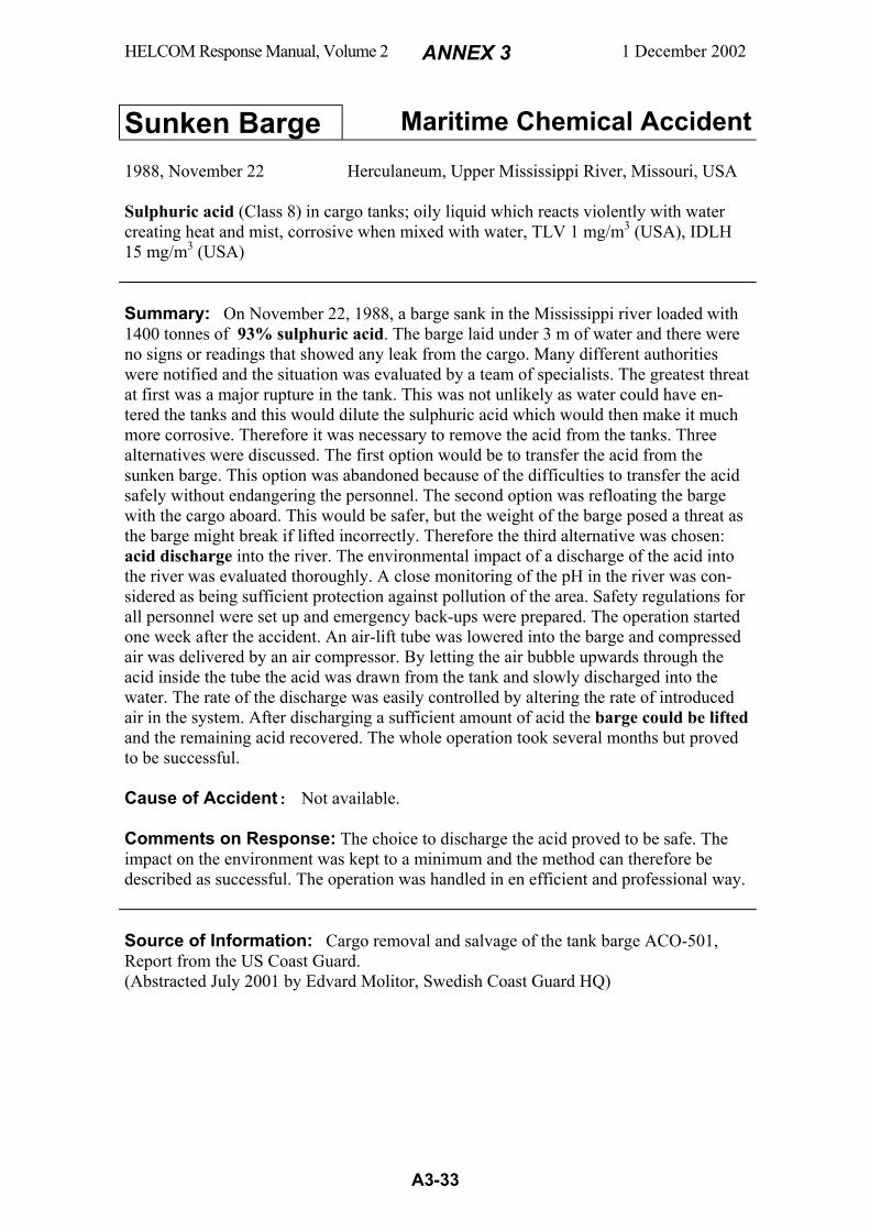
HELCOM Response Manual, Volume 2 ANNEX 3 1 December 2002
A3-33
Sunken Barge Maritime Chemical Accident
1988, November 22 Herculaneum, Upper Mississippi River, Missouri, USA Sulphuric acid (Class 8) in cargo tanks; oily liquid which reacts violently with water creating heat and mist, corrosive when mixed with water, TLV 1 mg/m3 (USA), IDLH 15 mg/m3 (USA) Summary: On November 22, 1988, a barge sank in the Mississippi river loaded with 1400 tonnes of 93% sulphuric acid. The barge laid under 3 m of water and there were no signs or readings that showed any leak from the cargo. Many different authorities were notified and the situation was evaluated by a team of specialists. The greatest threat at first was a major rupture in the tank. This was not unlikely as water could have en-tered the tanks and this would dilute the sulphuric acid which would then make it much more corrosive. Therefore it was necessary to remove the acid from the tanks. Three alternatives were discussed. The first option would be to transfer the acid from the sunken barge. This option was abandoned because of the difficulties to transfer the acid safely without endangering the personnel. The second option was refloating the barge with the cargo aboard. This would be safer, but the weight of the barge posed a threat as the barge might break if lifted incorrectly. Therefore the third alternative was chosen: acid discharge into the river. The environmental impact of a discharge of the acid into the river was evaluated thoroughly. A close monitoring of the pH in the river was con-sidered as being sufficient protection against pollution of the area. Safety regulations for all personnel were set up and emergency back-ups were prepared. The operation started one week after the accident. An air-lift tube was lowered into the barge and compressed air was delivered by an air compressor. By letting the air bubble upwards through the acid inside the tube the acid was drawn from the tank and slowly discharged into the water. The rate of the discharge was easily controlled by altering the rate of introduced air in the system. After discharging a sufficient amount of acid the barge could be lifted and the remaining acid recovered. The whole operation took several months but proved to be successful. Cause of Accident: Not available. Comments on Response: The choice to discharge the acid proved to be safe. The impact on the environment was kept to a minimum and the method can therefore be described as successful. The operation was handled in en efficient and professional way. Source of Information: Cargo removal and salvage of the tank barge ACO-501, Report from the US Coast Guard. (Abstracted July 2001 by Edvard Molitor, Swedish Coast Guard HQ)
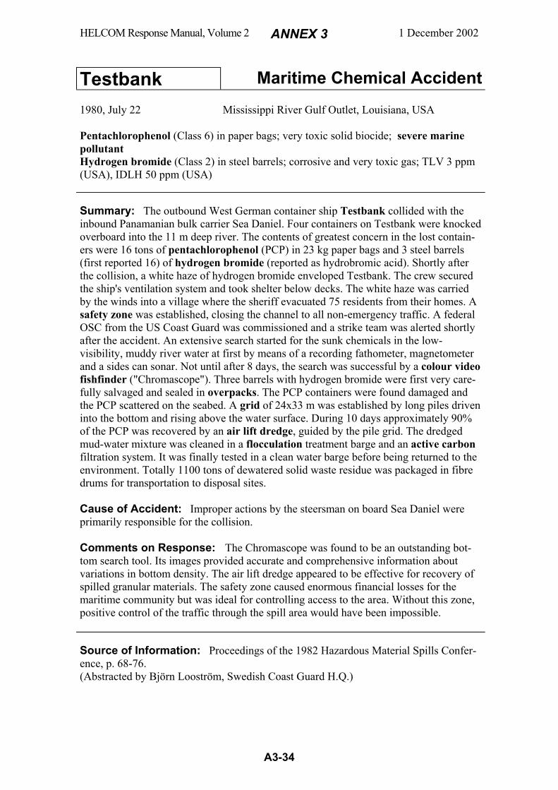
HELCOM Response Manual, Volume 2 ANNEX 3 1 December 2002
A3-34
Testbank Maritime Chemical Accident
1980, July 22 Mississippi River Gulf Outlet, Louisiana, USA Pentachlorophenol (Class 6) in paper bags; very toxic solid biocide; severe marine pollutant Hydrogen bromide (Class 2) in steel barrels; corrosive and very toxic gas; TLV 3 ppm (USA), IDLH 50 ppm (USA) Summary: The outbound West German container ship Testbank collided with the inbound Panamanian bulk carrier Sea Daniel. Four containers on Testbank were knocked overboard into the 11 m deep river. The contents of greatest concern in the lost contain-ers were 16 tons of pentachlorophenol (PCP) in 23 kg paper bags and 3 steel barrels (first reported 16) of hydrogen bromide (reported as hydrobromic acid). Shortly after the collision, a white haze of hydrogen bromide enveloped Testbank. The crew secured the ship's ventilation system and took shelter below decks. The white haze was carried by the winds into a village where the sheriff evacuated 75 residents from their homes. A safety zone was established, closing the channel to all non-emergency traffic. A federal OSC from the US Coast Guard was commissioned and a strike team was alerted shortly after the accident. An extensive search started for the sunk chemicals in the low-visibility, muddy river water at first by means of a recording fathometer, magnetometer and a sides can sonar. Not until after 8 days, the search was successful by a colour video fishfinder ("Chromascope"). Three barrels with hydrogen bromide were first very care-fully salvaged and sealed in overpacks. The PCP containers were found damaged and the PCP scattered on the seabed. A grid of 24x33 m was established by long piles driven into the bottom and rising above the water surface. During 10 days approximately 90% of the PCP was recovered by an air lift dredge, guided by the pile grid. The dredged mud-water mixture was cleaned in a flocculation treatment barge and an active carbon filtration system. It was finally tested in a clean water barge before being returned to the environment. Totally 1100 tons of dewatered solid waste residue was packaged in fibre drums for transportation to disposal sites. Cause of Accident: Improper actions by the steersman on board Sea Daniel were primarily responsible for the collision. Comments on Response: The Chromascope was found to be an outstanding bot-tom search tool. Its images provided accurate and comprehensive information about variations in bottom density. The air lift dredge appeared to be effective for recovery of spilled granular materials. The safety zone caused enormous financial losses for the maritime community but was ideal for controlling access to the area. Without this zone, positive control of the traffic through the spill area would have been impossible. Source of Information: Proceedings of the 1982 Hazardous Material Spills Confer-ence, p. 68-76. (Abstracted by Björn Looström, Swedish Coast Guard H.Q.)
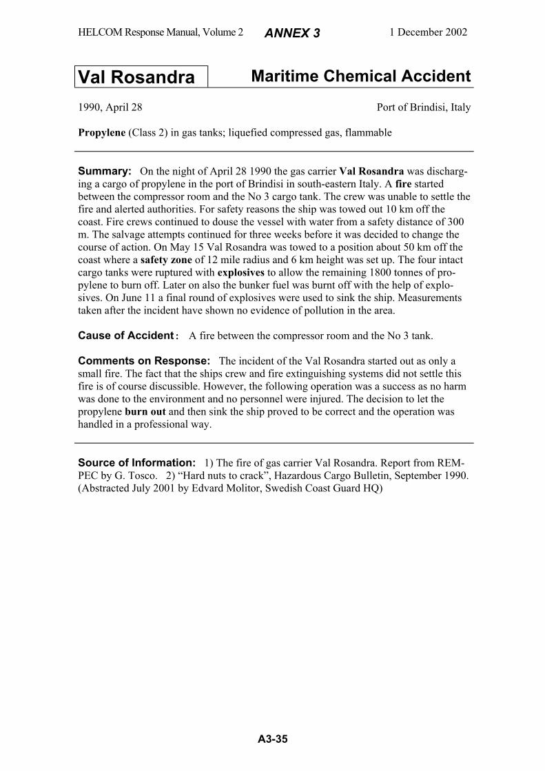
HELCOM Response Manual, Volume 2 ANNEX 3 1 December 2002
A3-35
Val Rosandra Maritime Chemical Accident
1990, April 28 Port of Brindisi, Italy Propylene (Class 2) in gas tanks; liquefied compressed gas, flammable Summary: On the night of April 28 1990 the gas carrier Val Rosandra was discharg-ing a cargo of propylene in the port of Brindisi in south-eastern Italy. A fire started between the compressor room and the No 3 cargo tank. The crew was unable to settle the fire and alerted authorities. For safety reasons the ship was towed out 10 km off the coast. Fire crews continued to douse the vessel with water from a safety distance of 300 m. The salvage attempts continued for three weeks before it was decided to change the course of action. On May 15 Val Rosandra was towed to a position about 50 km off the coast where a safety zone of 12 mile radius and 6 km height was set up. The four intact cargo tanks were ruptured with explosives to allow the remaining 1800 tonnes of pro-pylene to burn off. Later on also the bunker fuel was burnt off with the help of explo-sives. On June 11 a final round of explosives were used to sink the ship. Measurements taken after the incident have shown no evidence of pollution in the area. Cause of Accident: A fire between the compressor room and the No 3 tank. Comments on Response: The incident of the Val Rosandra started out as only a small fire. The fact that the ships crew and fire extinguishing systems did not settle this fire is of course discussible. However, the following operation was a success as no harm was done to the environment and no personnel were injured. The decision to let the propylene burn out and then sink the ship proved to be correct and the operation was handled in a professional way. Source of Information: 1) The fire of gas carrier Val Rosandra. Report from REM-PEC by G. Tosco. 2) “Hard nuts to crack”, Hazardous Cargo Bulletin, September 1990. (Abstracted July 2001 by Edvard Molitor, Swedish Coast Guard HQ)

HELCOM Response Manual, Volume 2 ANNEX 3 1 December 2002
A3-36
Viggo Hinrichsen Maritime Chemical Accident
1973, September 29 Baltic Sea, 1 n.m. north of Oland, Sweden Chromium trioxide (Class 5) in drums; corrosive and dangerous solid; powerful oxi-dizer that decomposes by heat to free oxygen and may cause fire and explosion in con-tact with combustibles; Sodium dichromate (Unclassified) in drums; both substances form corrosive chromic acid in water Summary: The West German dry cargo ship Viggo Hinrichsen encountered machin-ery failure during stormy weather on her way from Rotterdam to Rönnskär in northern Sweden. The ship was towed towards _land but listed during the tow and sank at the depth of 17 m, with a cargo of 234 tons of chromium trioxide in 1100 drums and 180 tons of sodium dichromate in 700 drums. All drums had removable heads. The cargo was stowed in the holds, except for 27 drums stowed on deck. Bottom water samples, taken the day after, showed that chromium compounds had started to leak out and dis-solve in the water. When informed of the leakage, responsible Swedish authorities jointly decided that the ship should be salvaged. The concentration of chromic acid was less than 1 g/l in the water close to the vessel and a few mg/l 100 m downstream. Three days after the accident, the place was treated with 11 tons of ferrosulphate that was poured onto the wreck from sacks that were cut open at the water surface. Ferrosulphate is a reducing agent that converts the chromic acid to a form which is less dangerous for the environment. During the towage, before the ship sank, 10 drum fell overboard. Eight of these drums were located by sonar equipment carried on a naval submarine salvage ship. Some of the drums were found damaged and empty. Six days after the accident two big pontoon cranes heaved the ship up to the surface and towed her hanging in the cranes to a port where the cargo was taken care of. The total loss of chromium com-pounds to the environment was estimated to 1-2 tons. The environmental damage was slight - some dead fish and jellyfish. The total cost of the operation was USD 3 millions in today's money value. Cause of Accident: Machinery failure during storm on undermanned ship (only 2 crew on board!). Cargo listed during tow and the ship sank. Comments on Response: The accident showed that better information is needed about what chemicals are transported in the Baltic Sea. Better general preparedness is also needed regarding response to chemical accidents at sea, including measures like chemical analysis of chemicals spreading in the water. After the operation some scien-tists claimed that the ferrosulphate treatment did not do any good - but not any harm either. In 1973, the responsibility was not stated in Sweden for actions against chemical accidents at sea. By this reason, the command responsibility was unclear. However, the year after, the Swedish Coast Guard was commissioned this responsibility. Source of Information: Brief reports (in Swedish) written by the different authori-ties involved in the operation. (Abstracted by Björn Looström, Swedish Coast Guard H.Q.)

HELCOM Response Manual, Volume 2 ANNEX 4 1 December 2002
A4-1
Classification of chemical spills in water and connection to related response methods
Property group definition flow chart
Figure a4 - 1
Flow chart of a joint European system for classification of chemical spills in water
Figure a4 - 1 shows a flow chart of a joint European system for classification of chemi-cal spills in water ("European Classification System"). The system is based on the physical behaviours in water (solubility, density, vapour pressure) and comprises 12
HELCOM Response Manual, Volume 2 ANNEX 4 1 December 2002
A4-2
Property Groups (G, GD, E, ED, etc.) for substances and 3 Groups for packages (PF, PI and PS). These groups are fully defined by Figure a4 - 1 (after a temperature is selected) and further explained by Figure a4 - 2. Property Group Designations for spilled chemicals in water
G gas FE floater/evaporator DE dissolver/evaporator GD gas/dissolver FED floater/evaporator/dissolver D dissolver E evaporator F floater SD sinker/dissolver
ED evaporator/dissolver FD floater/dissolver S sinker Figure a4 - 2
Property Group Designations for dropped packages in water
PF Package Floater PI Package Immersed PS Package Sinker
The package floats The package has the same bulk density
as water and is waterlogged
The package sinks w/v < ds - 0,01 w/v = ds ± 0,01 w/v > ds +0,01
w = the package’s gross weight, grams v = the package’s gross volume, millilitres ds = waters density, grams/millilitre
Figure a4 - 3 Examples of chemicals in the 12 Property Groups Group Properties Examples Evaporate G Evaporate immediately propane, butane, vinyl chloride Immediately (Gases)
GD evaporate immediately, dissolve
ammonia
Evaporate
E float, evaporate rapidly
benzene, hexane cyclohexane
Rapidly ED evaporate rapidly, dissolve
methyl-t-butyl ether vinyl acetate
FE float, evaporate
heptane, turpentine toluene, xylene
Float
FED float, evaporate, dissolve
butyl acetate isobutanol ethyl acrylate
F float Phthalates, vegetable oils, animal oils dipentene, isodecanol
FD float, dissolve
butanol butyl acrylate
Dissolve
DE dissolve rapidly, evaporate
Acetone, monoethylamine propylene oxide
D dissolve rapidly some acids and bases, some alcohols, glycols, some amines, methyl ethyl ketone
SD sink, dissolve
dichloromethane 1,2-dichloroethane
Sink S sink butyl benzyl phthalate, chlorobenzene creosote, coal tar, tetraethyl lead, tetramethyl lead
Figure a4 - 4
HELCOM Response Manual, Volume 2 ANNEX 5 1 December 2002
A5-1
Body protection levels When response activities are conducted where atmospheric contamination is known or suspected to exist, personal protective equipment must be worn. Personal protective equipment is designed to prevent/reduce skin and eye contact as well as inhalation or ingestion of the chemical substance. Protective equipment to protect the body against contact with known or anticipated chemical hazards has been divided into the four categories Level A-D.
Level A Level A protection should be worn when the highest level of respiratory, skin, eye and mucous membrane protection is needed. Personal Protective Equipment ● Positive pressure (pressure demand), self contained breathing apparatus, or positive-
pressure supplied air respirator with escape SCBA.
● Fully encapsulating chemical protective suit.
● Gloves, inner, chemical resistant.
● Gloves, outer, chemical resistant.
● Boots, chemical resistant, steel toe and shank; (depending on suit boot construction, worn over or under suit boot.)
● Underwear, cotton, long-john type.*
● Hard hat (under suit).*
● Coveralls (under suit).*
● Two-way radio communications (intrinsically safe/non-sparking).*
* Optional
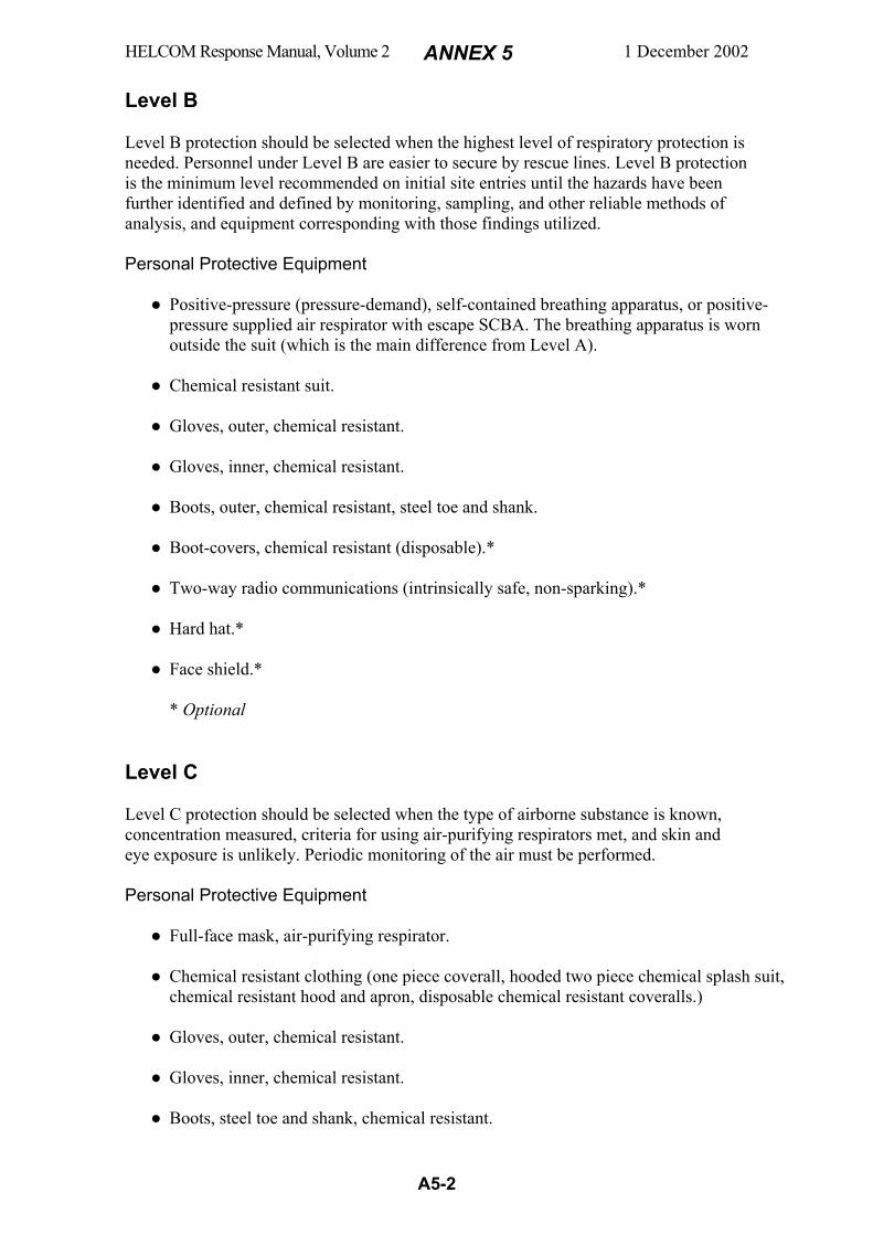
HELCOM Response Manual, Volume 2 ANNEX 5 1 December 2002
A5-2
Level B Level B protection should be selected when the highest level of respiratory protection is needed. Personnel under Level B are easier to secure by rescue lines. Level B protection is the minimum level recommended on initial site entries until the hazards have been further identified and defined by monitoring, sampling, and other reliable methods of analysis, and equipment corresponding with those findings utilized. Personal Protective Equipment ● Positive-pressure (pressure-demand), self-contained breathing apparatus, or positive-
pressure supplied air respirator with escape SCBA. The breathing apparatus is worn outside the suit (which is the main difference from Level A).
● Chemical resistant suit.
● Gloves, outer, chemical resistant.
● Gloves, inner, chemical resistant.
● Boots, outer, chemical resistant, steel toe and shank.
● Boot-covers, chemical resistant (disposable).*
● Two-way radio communications (intrinsically safe, non-sparking).*
● Hard hat.*
● Face shield.*
* Optional Level C Level C protection should be selected when the type of airborne substance is known, concentration measured, criteria for using air-purifying respirators met, and skin and eye exposure is unlikely. Periodic monitoring of the air must be performed. Personal Protective Equipment ● Full-face mask, air-purifying respirator.
● Chemical resistant clothing (one piece coverall, hooded two piece chemical splash suit,
chemical resistant hood and apron, disposable chemical resistant coveralls.)
● Gloves, outer, chemical resistant.
● Gloves, inner, chemical resistant.
● Boots, steel toe and shank, chemical resistant.
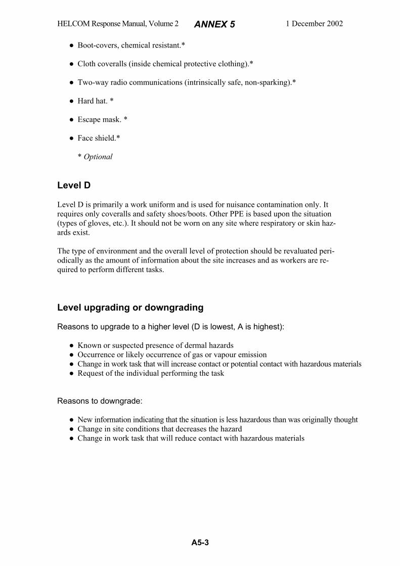
HELCOM Response Manual, Volume 2 ANNEX 5 1 December 2002
A5-3
● Boot-covers, chemical resistant.*
● Cloth coveralls (inside chemical protective clothing).*
● Two-way radio communications (intrinsically safe, non-sparking).*
● Hard hat. *
● Escape mask. *
● Face shield.*
* Optional Level D Level D is primarily a work uniform and is used for nuisance contamination only. It requires only coveralls and safety shoes/boots. Other PPE is based upon the situation (types of gloves, etc.). It should not be worn on any site where respiratory or skin haz-ards exist. The type of environment and the overall level of protection should be revaluated peri-odically as the amount of information about the site increases and as workers are re-quired to perform different tasks. Level upgrading or downgrading
Reasons to upgrade to a higher level (D is lowest, A is highest): ● Known or suspected presence of dermal hazards ● Occurrence or likely occurrence of gas or vapour emission ● Change in work task that will increase contact or potential contact with hazardous materials ● Request of the individual performing the task Reasons to downgrade: ● New information indicating that the situation is less hazardous than was originally thought ● Change in site conditions that decreases the hazard ● Change in work task that will reduce contact with hazardous materials
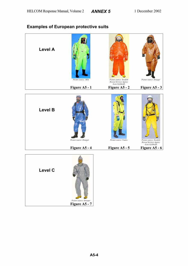
HELCOM Response Manual, Volume 2 ANNEX 5 1 December 2002
A5-4
Examples of European protective suits
Level A
Picture source: MSA Picture source: Swedish
Rescue Services Agency (Lars Gylldorff)
Picture source: Draeger
Figure A5 - 1 Figure A5 - 2 Figure A5 - 3
Level B
Picture source: Draeger Picture source: Vautex Picture source: Swedish
Rescue Services Agency (Lars Gylldorff)
Figure A5 - 4 Figure A5 - 5 Figure A5 - 6
Level C
Picture source: Draeger
Figure A5 - 7
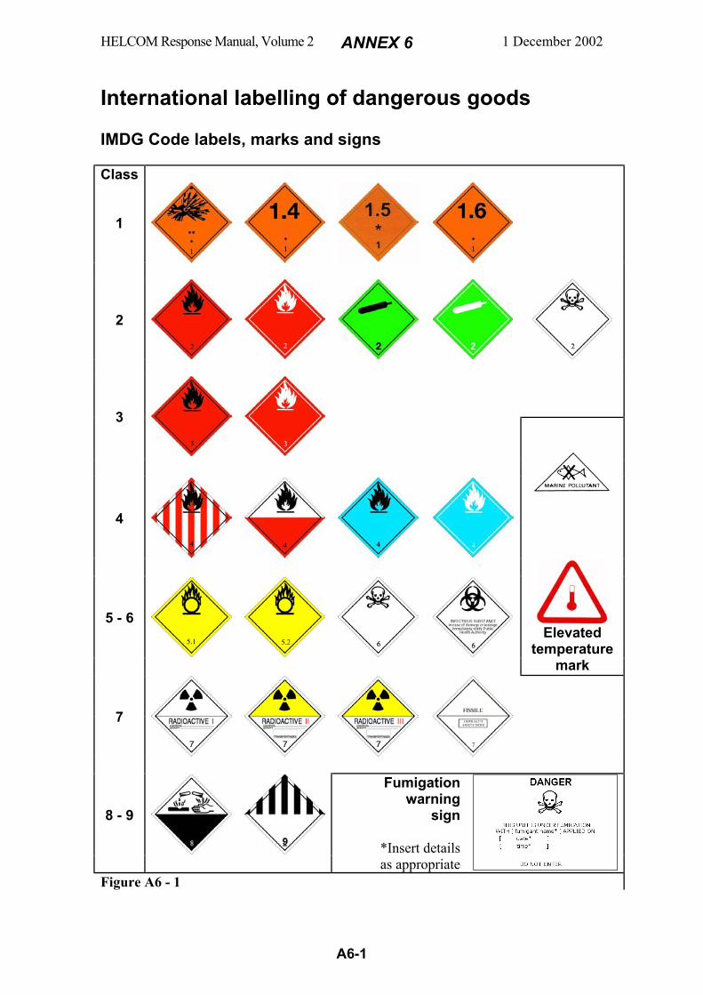
HELCOM Response Manual, Volume 2 ANNEX 6 1 December 2002
A6-1
International labelling of dangerous goods IMDG Code labels, marks and signs Class
1
2
3
4
5 - 6
Elevated
temperature mark
7
8 - 9
Fumigation warning
sign
*Insert details as appropriate
Figure A6 - 1
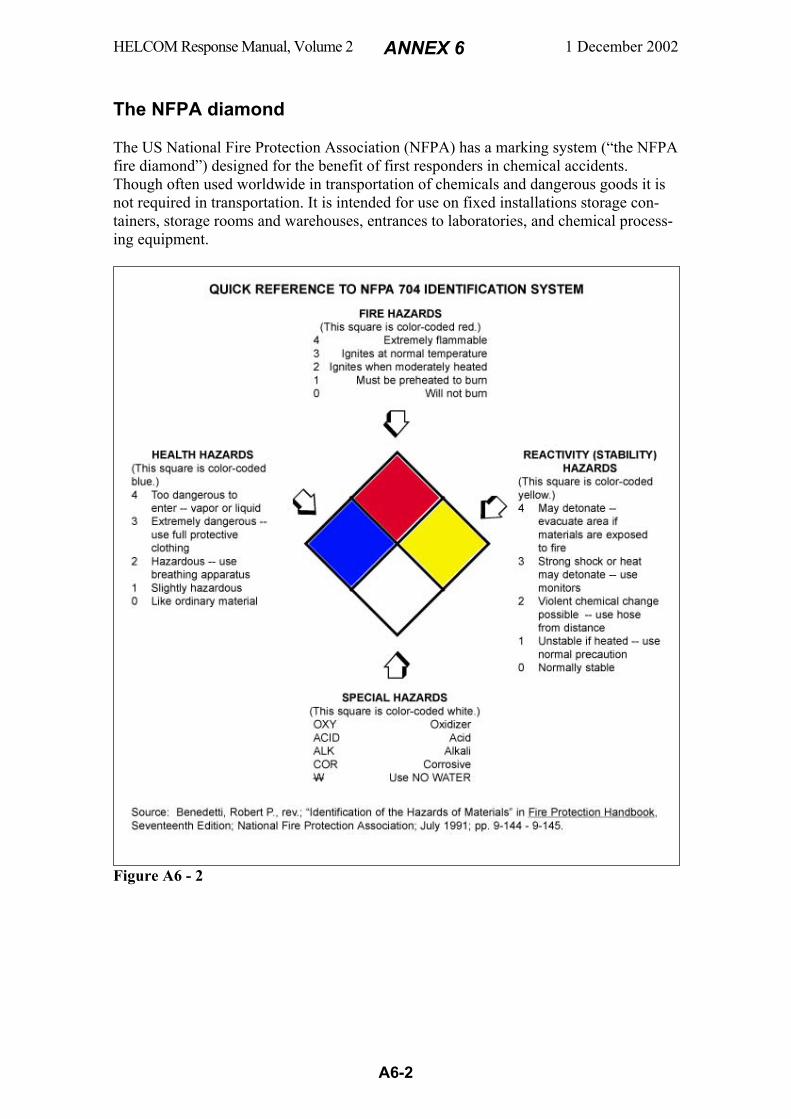
HELCOM Response Manual, Volume 2 ANNEX 6 1 December 2002
A6-2
The NFPA diamond The US National Fire Protection Association (NFPA) has a marking system (“the NFPA fire diamond”) designed for the benefit of first responders in chemical accidents. Though often used worldwide in transportation of chemicals and dangerous goods it is not required in transportation. It is intended for use on fixed installations storage con-tainers, storage rooms and warehouses, entrances to laboratories, and chemical process-ing equipment.
Figure A6 - 2
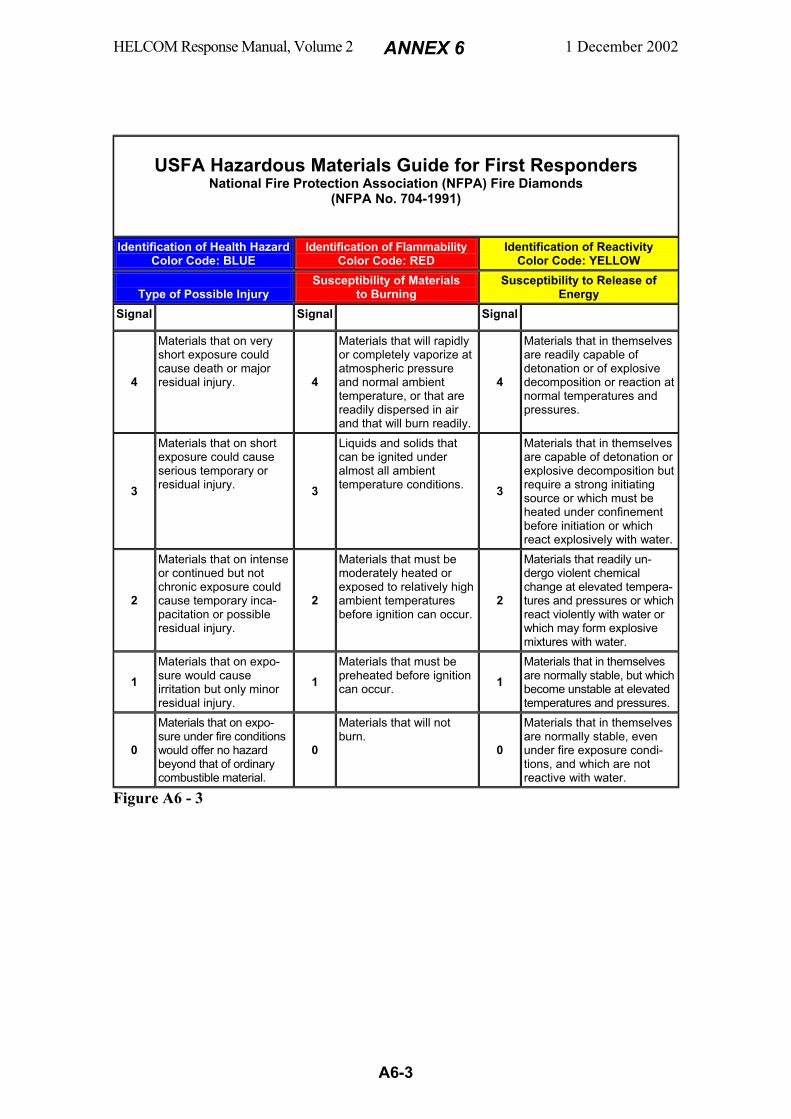
HELCOM Response Manual, Volume 2 ANNEX 6 1 December 2002
A6-3
USFA Hazardous Materials Guide for First Responders National Fire Protection Association (NFPA) Fire Diamonds
(NFPA No. 704-1991)
Identification of Health Hazard Color Code: BLUE
Identification of Flammability Color Code: RED
Identification of Reactivity Color Code: YELLOW
Type of Possible Injury
Susceptibility of Materials to Burning
Susceptibility to Release of Energy
Signal Signal Signal
4
Materials that on very short exposure could cause death or major residual injury. 4
Materials that will rapidly or completely vaporize at atmospheric pressure and normal ambient temperature, or that are readily dispersed in air and that will burn readily.
4
Materials that in themselves are readily capable of detonation or of explosive decomposition or reaction at normal temperatures and pressures.
3
Materials that on short exposure could cause serious temporary or residual injury. 3
Liquids and solids that can be ignited under almost all ambient temperature conditions. 3
Materials that in themselves are capable of detonation or explosive decomposition but require a strong initiating source or which must be heated under confinement before initiation or which react explosively with water.
2
Materials that on intense or continued but not chronic exposure could cause temporary inca-pacitation or possible residual injury.
2
Materials that must be moderately heated or exposed to relatively high ambient temperatures before ignition can occur.
2
Materials that readily un-dergo violent chemical change at elevated tempera-tures and pressures or which react violently with water or which may form explosive mixtures with water.
1 Materials that on expo-sure would cause irritation but only minor residual injury.
1 Materials that must be preheated before ignition can occur. 1
Materials that in themselves are normally stable, but which become unstable at elevated temperatures and pressures.
0
Materials that on expo-sure under fire conditions would offer no hazard beyond that of ordinary combustible material.
0
Materials that will not burn.
0
Materials that in themselves are normally stable, even under fire exposure condi-tions, and which are not reactive with water.
Figure A6 - 3
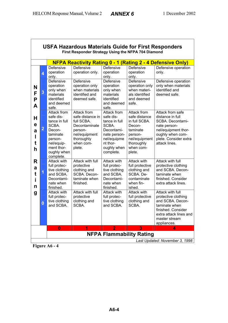
HELCOM Response Manual, Volume 2 ANNEX 6 1 December 2002
A6-4
USFA Hazardous Materials Guide for First Responders
First Responder Strategy Using the NFPA 704 Diamond
NFPA Reactivity Rating 0 - 1 (Rating 2 - 4 Defensive Only) 4
Defensive operation only.
Defensive operation only.
Defensive operation only.
Defensive operation only.
Defensive operation only.
3
Defensive operation only when materials identified and deemed safe.
Defensive operation only when materials identified and deemed safe.
Defensive operation only when materials identified and deemed safe.
Defensive operation only when materi-als identified and deemed safe.
Defensive operation only when materials identified and deemed safe.
2
Attack from safe dis-tance in full SCBA. Decon-taminate person-nel/equip-ment thor-oughly when complete.
Attack from safe distance in full SCBA. Decontaminate person-nel/equipment thoroughly when com-plete.
Attack from safe dis-tance in full SCBA. Decontami-nate person-nel/equipment thor-oughly when complete.
Attack from safe distance in full SCBA. Decon-taminate person-nel/equipment thoroughly when com-plete.
Attack from safe distance in full SCBA. Decontami-nate person-nel/equipment thor-oughly when com-plete. Consider extra attack lines.
1
Attack with full protec-tive clothing and SCBA. Decontami-nate when finished.
Attack with full protective clothing and SCBA. Decon-taminate when finished.
Attack with full protec-tive clothing and SCBA. Decontami-nate when finished.
Attack with full protective clothing and SCBA. De-contaminate when fin-ished.
Attack with full protective clothing and SCBA. Decon-taminate when finished. Consider extra attack lines.
N F P A
H e a l t h
R a t i n g
0
Attack with full protec-tive clothing and SCBA.
Attack with full protective clothing and SCBA.
Attack with full protec-tive clothing and SCBA.
Attack with full protective clothing and SCBA.
Attack with full protective clothing and SCBA. Decon-taminate when finished. Consider extra attack lines and master stream appliances.
0 1 2 3 4 NFPA Flammability Rating
Last Updated: November 3, 1998 Figure A6 - 4
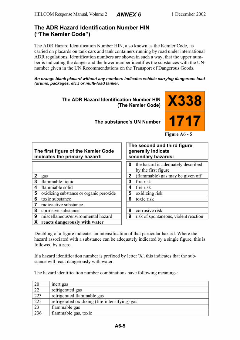
HELCOM Response Manual, Volume 2 ANNEX 6 1 December 2002
A6-5
The ADR Hazard Identification Number HIN (“The Kemler Code”) The ADR Hazard Identification Number HIN, also known as the Kemler Code, is carried on placards on tank cars and tank containers running by road under international ADR regulations. Identification numbers are shown in such a way, that the upper num-ber is indicating the danger and the lower number identifies the substances with the UN-number given in the UN Recommendations on the Transport of Dangerous Goods. An orange blank placard without any numbers indicates vehicle carrying dangerous load (drums, packages, etc.) or multi-load tanker.
The ADR Hazard Identification Number HIN (The Kemler Code)
The substance’s UN Number
Figure A6 - 5 The first figure of the Kemler Code indicates the primary hazard:
The second and third figure generally indicate secondary hazards:
0 the hazard is adequately described by the first figure
2 gas 2 (flammable) gas may be given off 3 flammable liquid 3 fire risk 4 flammable solid 4 fire risk 5 oxidizing substance or organic peroxide 5 oxidizing risk 6 toxic substance 6 toxic risk 7 radioactive substance 8 corrosive substance 8 corrosive risk 9 miscellaneous/environmental hazard 9 risk of spontaneous, violent reaction X reacts dangerously with water
Doubling of a figure indicates an intensification of that particular hazard. Where the hazard associated with a substance can be adequately indicated by a single figure, this is followed by a zero.
If a hazard identification number is prefixed by letter 'X', this indicates that the sub-stance will react dangerously with water.
The hazard identification number combinations have following meanings:
20 inert gas 22 refrigerated gas 223 refrigerated flammable gas 225 refrigerated oxidizing (fire-intensifying) gas 23 flammable gas 236 flammable gas, toxic
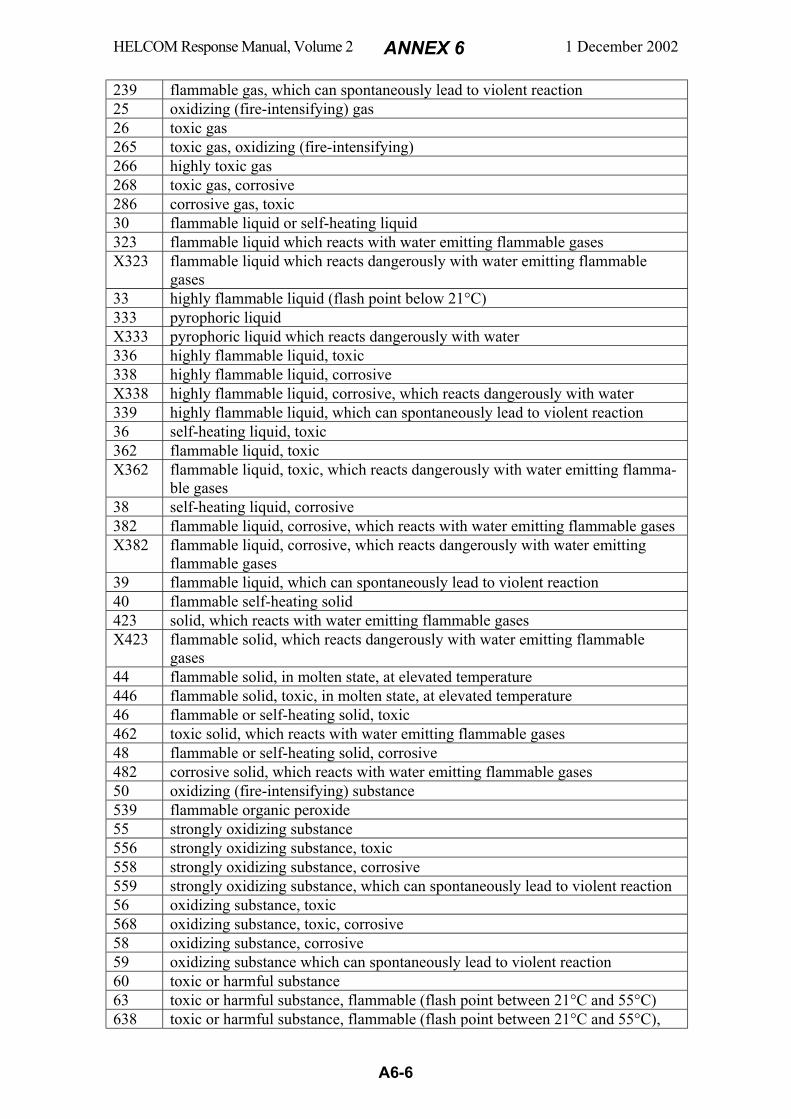
HELCOM Response Manual, Volume 2 ANNEX 6 1 December 2002
A6-6
239 flammable gas, which can spontaneously lead to violent reaction 25 oxidizing (fire-intensifying) gas 26 toxic gas 265 toxic gas, oxidizing (fire-intensifying) 266 highly toxic gas 268 toxic gas, corrosive 286 corrosive gas, toxic 30 flammable liquid or self-heating liquid 323 flammable liquid which reacts with water emitting flammable gases X323 flammable liquid which reacts dangerously with water emitting flammable
gases 33 highly flammable liquid (flash point below 21°C) 333 pyrophoric liquid X333 pyrophoric liquid which reacts dangerously with water 336 highly flammable liquid, toxic 338 highly flammable liquid, corrosive X338 highly flammable liquid, corrosive, which reacts dangerously with water 339 highly flammable liquid, which can spontaneously lead to violent reaction 36 self-heating liquid, toxic 362 flammable liquid, toxic X362 flammable liquid, toxic, which reacts dangerously with water emitting flamma-
ble gases 38 self-heating liquid, corrosive 382 flammable liquid, corrosive, which reacts with water emitting flammable gases X382 flammable liquid, corrosive, which reacts dangerously with water emitting
flammable gases 39 flammable liquid, which can spontaneously lead to violent reaction 40 flammable self-heating solid 423 solid, which reacts with water emitting flammable gases X423 flammable solid, which reacts dangerously with water emitting flammable
gases 44 flammable solid, in molten state, at elevated temperature 446 flammable solid, toxic, in molten state, at elevated temperature 46 flammable or self-heating solid, toxic 462 toxic solid, which reacts with water emitting flammable gases 48 flammable or self-heating solid, corrosive 482 corrosive solid, which reacts with water emitting flammable gases 50 oxidizing (fire-intensifying) substance 539 flammable organic peroxide 55 strongly oxidizing substance 556 strongly oxidizing substance, toxic 558 strongly oxidizing substance, corrosive 559 strongly oxidizing substance, which can spontaneously lead to violent reaction 56 oxidizing substance, toxic 568 oxidizing substance, toxic, corrosive 58 oxidizing substance, corrosive 59 oxidizing substance which can spontaneously lead to violent reaction 60 toxic or harmful substance 63 toxic or harmful substance, flammable (flash point between 21°C and 55°C) 638 toxic or harmful substance, flammable (flash point between 21°C and 55°C),

HELCOM Response Manual, Volume 2 ANNEX 6 1 December 2002
A6-7
corrosive 639 toxic or harmful substance, flammable (flash point between 21°C and 55°C),
which can spontaneously lead to violent reaction 66 highly toxic substance 663 highly toxic substance (flash point not above 55°C) 68 toxic or harmful substance, corrosive 69 toxic or harmful substance, which can spontaneously lead to violent reaction 70 radioactive material 72 radioactive gas 723 radioactive gas, flammable 73 radioactive liquid, flammable (flash point not above 55°C) 74 radioactive solid, flammable 75 radioactive material, oxidizing 76 radioactive material, toxic 78 radioactive material, corrosive 80 corrosive or slightly corrosive substance X80 corrosive or slightly corrosive substance, which reacts dangerously with water 83 corrosive or slightly corrosive substance, flammable (flash point between 21°C
and 55°C) X83 corrosive or slightly corrosive substance, flammable (flash point between 21°C
and 55°C), , which reacts dangerously with water 839 corrosive or slightly corrosive substance, flammable (flash point between 21°C
and 55°C), which can spontaneously lead to violent reaction X839 corrosive or slightly corrosive substance, flammable (flash point between 21°C
and 55°C), which can spontaneously lead to violent reaction and which reacts dangerously with water
85 corrosive or slightly corrosive substance, oxidizing (fire-intensifying) 856 corrosive or slightly corrosive substance, oxidizing (fire-intensifying) and toxic 86 corrosive or slightly corrosive substance, toxic 88 highly corrosive substance X88 highly corrosive substance, which reacts dangerously with water 883 highly corrosive substance, flammable (flash point between 21°C and 55°C) 885 highly corrosive substance, oxidizing (fire-intensifying) 886 highly corrosive substance, toxic X886 highly corrosive substance, toxic, which reacts dangerously with water 89 corrosive or slightly corrosive substance, which can spontaneously lead to
violent reaction 90 miscellaneous dangerous substance
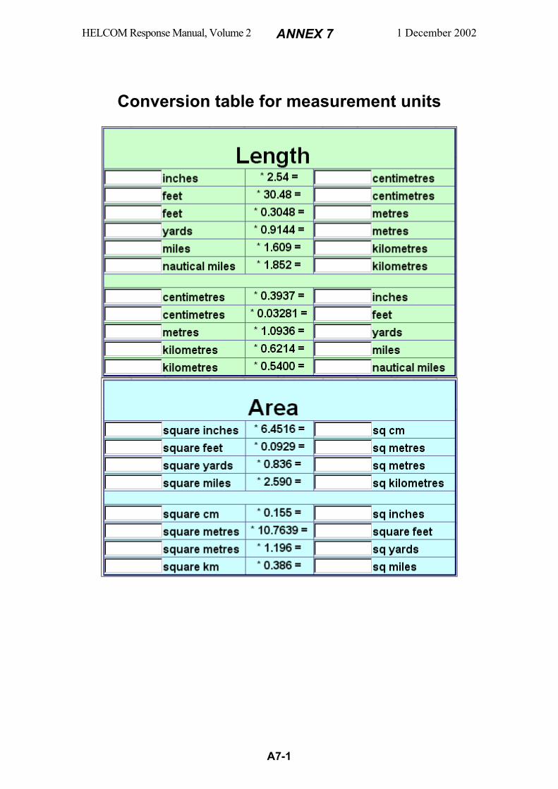
HELCOM Response Manual, Volume 2 ANNEX 7 1 December 2002
A7-1
Conversion table for measurement units
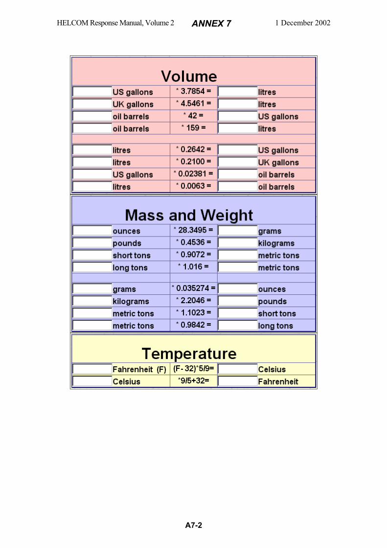
HELCOM Response Manual, Volume 2 ANNEX 7 1 December 2002
A7-2
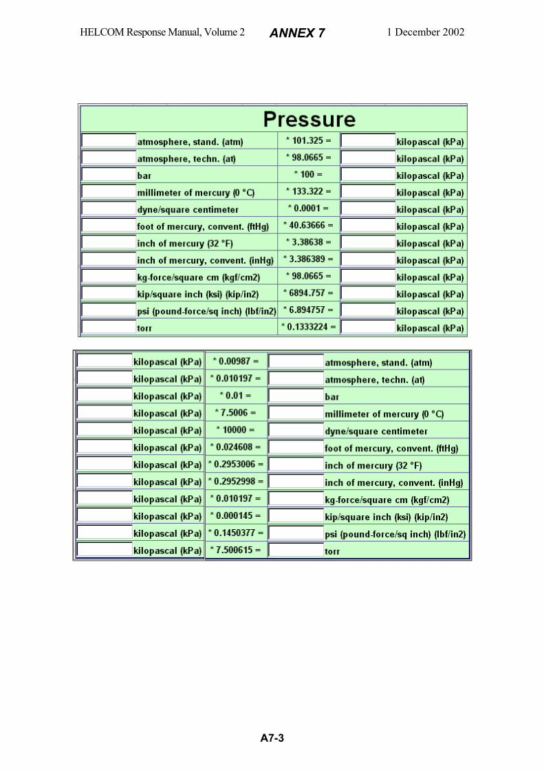
HELCOM Response Manual, Volume 2 ANNEX 7 1 December 2002
A7-3
HELCOM Response Manual, Volume 2 ANNEX 8 1 December 2002
A8-1
REFERENCES
1 International Maritime Organization, IMO, 4 Albert Embankment, London SE1
7SR, England, Manual on Chemical Pollution a) - Section 1 - Problem Assessment and Response Arrangement (1987).
b) - Section 2 - Search and Recovery of Packaged Goods Lost at Sea (1991).
2 Swedish Coast Guard, Räddningstjänstplan - Miljöräddningstjänst till sjöss (in Swedish), Karlskrona, Sweden, 2000.
3 IMO/UNEP: Regional Information System, Part D, Operational Guides and Tech-
nical Manuals, Section 12, Practical Guide for Marine Chemical Spills, REM-PEC, June 1999, updated January 2000.
4 US Coast Guard, US Department of Transportation, CHRIS Chemical Hazards
Response Information System - Hazardous Chemical Data Manual, US Gov-ernment Printing Office, Superintendent of Documents, P.O. Box 371954, Pitts-burgh, PA 15250-7954, USA, 1999 (Order No. 050-012-00406-4). http://www.uscg.mil/hq/g-m/mor/articles/chris.htm http://www.chrismanual.com/
5 US Environmental Protection Agency, Standard Operating Safety Guides, Office
of Emergency and Remedial Response, US Environmental Protection Agency, Washington, DC 20460, USA, 1992, NTIS Publication 9285.1-03.
6 CAMEO, US National Safety Council, Customer Service, Box 558, Itasca IL
60143-0558, USA, Fax +1 708 285 0797. 7 Shell International, Chemspil, Reports No. HSE 90.006, HSE 90.007 and HSE
90.008, Shell Internationale Petroleum Maatschappij B.V., The Hague, Holland, 1990.
8 Ashworth P., A Dispersion Model for Sinker Liquids Spilled into Waterways,
1982 Hazardous Material Spills Conference Proceedings, Bureau of Explosives; Chemical Manufacturers Association; US Coast Guard; US Environmental Pro-tection Agency, Milwaukee, Wisconsin, USA, 19-22 April 1982, p.404-413.
9 Salo S., The Fate of Chemicals Spilled on Water - A Literature Review of Physi-
cal and Chemical Processes, Vesi-ja Ympäristöhallitus, Helsinki, Finland, 1992. 10 Koponen J., Salo S. and Hirvi J.-P., Description of a Computer Program for
Chemical Spill Simulation, Mimeograph Series of the National Board of Waters and the Environment No. 440, Helsinki, Finland, 1992.
11 Szluha A.T. et al., Response Manual for Combating Spills of Floating Hazard-
ous CHRIS Chemicals, MAXIMA Corporation, Environmental Technology Division, 107 Union Valley Road, Oak Ridge, TE 37830, USA, 1989.
HELCOM Response Manual, Volume 2 ANNEX 8 1 December 2002
A8-2
12 Szluha A.T. et al., Review of Technologies for Containment and Recovery of
Floating Hazardous Chemicals, 1986 Hazardous Material Spills Conference Proceedings, Association of American Railroads; US Coast Guard; Chemical Manufacturers Association; US Environmental Protection Agency, St. Louis, Missouri, USA, 5-8 May 1986, p.65-71.
13 Kartlegging av Absorberende Midler, Report 93:21, 1993, Norwegian Pollution
Control Authority, Pb 8100 Dep, 0032 Oslo, Norway 14 Melvold R.W. and Gibson S.C., A Guidance Manual for Selection and Use of
Sorbents for Liquid Hazardous Substances, JRB Associates Inc., McLean, VA, USA, 1987, NTIS Report PB87-208765.
15 Herrick E.C., Carstea D. and Goldgraben G., Sorbent Materials for Cleanup of
Hazardous Spills, MITRE Corporation, McLean, VA, USA, 1982, NTIS Report PB82-227125.
16 Imbiber Beads: http://www.imbiberbeads.com/ 17 Breslin M.K. and Royer M.D., Use of Selected Sorbents and an Aqueous Film
Forming Foam on Floating Hazardous Materials, JRB Associates Inc., McLean, VA, USA, 1981, NTIS Report PB82-108895.
18 McCracken W.E. and Schwartz S.H., Performance Testing of Spills Control
Devices on Floatable Hazardous Materials, US Coast Guard, US Environmental Protection Agency, Office of Research and Development, Cincinnati, OH, USA, 1977, NTIS Report PB 276581.
19 Akers C.K. et al., Guidelines for the Use of Chemicals in Removing Hazardous
Substance Discharges, Calspan Corporation, Buffalo, NY 14221, USA, 1981, NTIS Report PB82-107483.
20 Drake E. et al., A Feasibility Study of Response Techniques for Discharges of
Hazardous Chemicals that Disperse through the Water Column, Arthur D. Little Inc., Acorn Park, Cambridge, MA 02140, USA, 1976, NTIS Report AD-A040968.
21 Bauer W.H., Borton D.N. and Bulloff J.J., Agents, Methods and Devices for
Amelioration of Discharges of Hazardous Chemicals on Water, Rensselear Polytechnic Institute, 110 Eighth Street, Troy, NY 12181, USA, 1975, NTIS Report AD-A024221.
22 Shooter D., Lyman W.J. and Sinclair J.R., Response Techniques for Spills of
Hazardous, Water Soluble Chemicals, Paper (not in Proceedings) presented at the 1980 National Conference on Control of Hazardous Material Spills, US Environ-mental Protection Agency and US Coast Guard, Louisville, Kentucky, USA, 13-15 May 1980.
23 Thornton G.J.E., Williams J.E. and Clements R.J., Response to a Major Dis-
charge of Pentachlorophenol in a Waterway, 1982 Hazardous Material Spills Conference Proceedings, Bureau of Explosives; Chemical Manufacturers Associa-tion; US Coast Guard; US Environmental Protection Agency, Milwaukee, Wis-
HELCOM Response Manual, Volume 2 ANNEX 8 1 December 2002
A8-3
consin, USA, 19-22 April 1982, p.68-76. 24 Willmann J.C., Blazevich J. and Snyder, JR., H.J., PCB Spill in the Duwamish-
Seattle, WA., Control of Hazardous Material Spills: Proceedings of the 1976 National Conference on Control of Hazardous Material Spills, US Environmental Protection Agency and Oil Spill Control Association of America, New Orleans, Louisiana, USA, 25-28 April 1976, p.351-355.
25 Daniels S.L., Product Stewardship for Chemicals Used in Water and Wastewater
Treatment, Control of Hazardous Material Spills: Proceedings of the 1974 Na-tional Conference on Control of Hazardous Material Spills, American Institute of Chemical Engineers and US Environmental Protection Agency, San Francisco, California, USA, 25-28 August 1974, p.31-37.
26 Dawson G.W., McNeese J.A. and Coates J.A., Application of Buoyant Mass
Transfer Media to Hazardous Material Spills, Batelle Pacific Northwest Labora-tories, Richland, Washington 99352, USA, 1980, NTIS Report PB80-198427.
27 Dawson et al., In Situ Treatment of Hazardous Material Spills in Flowing
Streams, Batelle Northwest, Richland, Washington 99352, USA, 1977, NTIS Report PB 274455.
28 Dawson G.W., Mercer B.W. and Parkhurst R.G., Comparative Evaluation of in
Situ Approaches to the Treatment of Flowing Streams, Control of Hazardous Material Spills: Proceedings of the 1976 National Conference on Control of Haz-ardous Material Spills, US Environmental Protection Agency and Oil Spill Con-trol Association of America, New Orleans, Louisiana, USA, 25-28 April 1976, p.266-271.
29 Mercer B.W., Shuckrow A.J. and Dawson G.W., Treatment of Hazardous Mate-
rial Spills with Floating Mass Transfer Media, US Environmental Protection Agency, USA, 1973, EPA-670/2-73-078, Superintendent of Documents, US Gov-ernment Printing Office, Washington D.C. 40402, USA.
30 Schneider G.R., Removal of Water-Soluble Hazardous Materials Spills from
Waterways by Activated Carbon, Control of Hazardous Material Spills: Proceed-ings of the 1980 National Conference on Control of Hazardous Material Spills, US Environmental Protection Agency and US Coast Guard, Louisville, Ken-tucky, USA, 13-15 May 1980, p.82-87.
31 Weston R.R., Selecting a Treatment Technique for Contaminated Bottom Sedi-
ments, 1982 Hazardous Material Spills Conference Proceedings, Bureau of Ex-plosives; Chemical Manufacturers Association; US Coast Guard; US Environ-mental Protection Agency, Milwaukee, Wisconsin, USA, 19-22 April 1982, p.102-110.
HELCOM Response Manual, Volume 2 ANNEX 8 1 December 2002
A8-4
32 Bonham N., Response Techniques for the Cleanup of Sinking Hazardous Mate-rials, Technology Development and Technical Services Branch, Environmental Protection, Conservation and Protection, Environment Canada, Ottawa, Ontario, Canada, K1A 0E7, Report EPS 4/SP/1, April 1989.
33 Boyer K.R., Hodge V.E. and Wetzel R.S., Handbook: Response to Discharges of
Sinking Hazardous Substances, Hazardous Waste Engineering Research Labora-tory, US Environmental Protection Agency, Cincinnati, OH 45268, USA, EPA/540/2-87/001, September 1987.
34 Hansen C.A. and Sanders R G., Removal of Hazardous Material Spills from
Bottoms of Flowing Waterbodies, Municipal Environmental Research Labora-tory, Office of Research and Development, US Environmental Protection Agency, Cincinnati, OH 45268, USA, 1981, NTIS Report PB81-230922.
35 Goodier J.L. and Thompson C.H., In-Place Removal of Spilled Toxics: Available
Tools, Control of Hazardous Material Spills: Proceedings of the 1980 National Conference on Control of Hazardous Material Spills, US Environmental Protec-tion Agency and US Coast Guard, Louisville, Kentucky, USA, 13-15 May 1980, p.123-133.
36 Hand T.D. et al., Feasibility Study of Response Techniques for Discharges of
Hazardous Chemicals that sink, US Army Engineer Waterways Experiment Station, PO Box 631, Vicksburg, MS 39180, USA, June 1978.
37 Hand T.D. and Ford A.W., The Feasibility of Dredging for Bottom Recovery of
Spills of Dense, Hazardous Chemicals, Control of Hazardous Material Spills: Proceedings of the 1978 National Conference on Control of Hazardous Material Spills, US Environmental Protection Agency; US Coast Guard; Hazardous Mate-rials Control Research Institute, Miami Beach, Florida, USA, 11-13 April 1978, p.315-324.
38 Wiltshire G.A. and Rand M., Cargo Removal and Salvage of the Tank Barge
ACO-501, 1990 Hazardous Material Spills Conference Proceedings, American Institute of Chemical Engineers; National Response Team; Chemical Manufactur-ers Association , Houston, Texas, USA, 13-17 May 1990, p.619-633.
39 Solsberg L.B., Parent R.D. and Ross S.L., A Survey of Chemical Spill Counter-
measures, Environmental Emergencies Technology Division, Technology Devel-opment and Technical Services Branch, Conservation and Protection, Environ-ment Canada, Ottawa, Ontario, Canada, K1A 0E7, Report EPS 9/SP/2 December 1986.
40 International Maritime Dangerous Goods Code (IMDG-Code), Volume I-IV and
supplement (updated regularly), International Maritime Organization, London, UK.
41 Aoustin Y. and Cabioc’h F., Criteria for Decision Making Regarding Response
to Accidently Spilled Chemicals in Packaged Form - Hydrodynamic Aspects, IFREMER, Centre de Brest, BP. 70, 29280 Plouzane, France, 1992.
42 Cabioc’h F., The Behaviour and Fate of Packages Lost at Sea: A Report Based

HELCOM Response Manual, Volume 2 ANNEX 8 1 December 2002
A8-5
on Studies Carried Out for the French Administration and the European Com-mission, CEDRE, Centre for Documentation Research & Investigation into Acci-dental Water Pollution Incidents, Centre de Brest, BP. 70, 29280 Plouzane, France, 1991.
43 Cabioc’h F. et al Containers and Packages Lost at Sea – Operational Guide,
(French original‘s title: Conteneurs et colis perdus en mer – Guide Opérationnel), CEDRE 2001, France.
44 Eden A. van, Destruction of Chlorine Containers on the Sea Floor of the North
Sea, 1986 Hazardous Material Spills Conference Proceedings, Association of American Railroads; US Coast Guard; Chemical Manufacturers Association; US Environmental Protection Agency, St. Louis, Missouri, USA, 5-8 May 1986, p.25-35.
45 Saltveit S.J. and Brabrand Å., Utslipp av syre fra Idun fabrikker - en vurdering
av virking på bunndyr og fisk, Inland Water Ecology and Fishery Laboratory, Zoological Museum, Oslo University, Norway, Reg. No.1, 1988.
46 Harsh K.M., Toxicity Modification of an Anhydrous Ammonia Spill, Control of
Hazardous Material Spills: Proceedings of the 1978 National Conference on Con-trol of Hazardous Material Spills, US Environmental Protection Agency; US Coast Guard; Hazardous Materials Control Research Institute, Miami Beach, Florida, USA, 11-13 April 1978, p.148-151.
47 Mark C.G. et al., Case History of the MV Rio Neuquen: Containment and
Ocean Disposal of Reacting Aluminum Phosphide, 1986 Hazardous Material Spills Conference Proceedings, Association of American Railroads; US Coast Guard; Chemical Manufacturers Association; US Environmental Protection Agency, St. Louis, Missouri, USA, 5-8 May 1986, p.19-24.
48 Robinson J.S., Hazardous Chemical Spill Cleanup, Noyes Data Corporation,
Park Ridge, New Jersey, USA, 1979. 49 US Coast Guard, US Department of Transportation, CHRIS Chemical Hazards
Response Information System - Response Methods Handbook, US Government Printing Office, Superintendent of Documents, P.O. Box 371954, Pittsburgh, PA 15250-7954, USA, 1975 (Probably out of stock). http://www.uscg.mil/hq/g-m/mor/articles/chris.htm http://www.chrismanual.com/
50 BMT Marine Information Systems Limited, Grove House, Meridians Cross,
7 Ocean Way, Ocean Village, Southampton, SO14 3TJ, UK Tel: +44 23 8023 2222 Fax: +44 23 8023 2891 Email: [email protected] Web: www.bmtmis.com
51 Chou J., Hazardous Gas Monitors: A Practical Guide to Selection, Operation
and Applications, McGraw-Hill and SciTech Publishing, 1999. http://www.gotgas.com/book/
52 Jadamec J.R., Bentz A.P., Hiltabrand R.R. och Kleineberg G.A., The U.S. Coast
Guard Mobile Response Laboratory, 1984 Hazardous Material Spills Conference
HELCOM Response Manual, Volume 2 ANNEX 8 1 December 2002
A8-6
Proceedings, Association of American Railroads/Bureau of Explosives; Chemical Manufacturers Association; US Coast Guard; US Environmental Protection Agency, Nashville Tennessee, USA, 9-12 April 1984, p. 199-204.
53 Urban M. och Losche R., Development and Use of a Mobile Chemical Labora-
tory for Hazardous Material Spill Response Activities, Control of Hazardous Material Spills: Proceedings of the 1978 National Conference on Control of Haz-ardous Material Spills, US Environmental Protection Agency; US Coast Guard; Hazardous Materials Control Research Institute, Miami Beach, Florida, USA, 11-13 April 1978, p. 311-314.
54 Offenhartz B.H. och Lefko J.L., Enzyme-Based Detection of Chlorinated Hydro-
carbons, 1984 Hazardous Material Spills Conference Proceedings, Association of American Railroads/Bureau of Explosives; Chemical Manufacturers Association; US Coast Guard; US Environmental Protection Agency, Nashville Tennessee, USA, 9-12 April 1984, p. 195-198.
55 Skovronek H.S. et al., Hazardous Substance Detection by Canine Olfaction,
1986 Hazardous Material Spills Conference (article not included in the Proceed-ings), Association of American Railroads; US Coast Guard; Chemical Manufac-turers Association; US Environmental Protection Agency, St. Louis, Missouri, USA, 5-8 May 1986.
56 US Environmental Protection Agency, Delineating Toxic Areas by Canine Olfac-
tion, Project Summary EPA/600/S2-85/089, December 1985 57 Arner L.D., Johnson G.R., Masters H. och Skovronek H.S., Toxic Area Delinea-
tion by Canine Olfaction, 1984 Hazardous Material Spills Conference Proceed-ings, Association of American Railroads/Bureau of Explosives; Chemical Manu-facturers Association; US Coast Guard; US Environmental Protection Agency, Nashville Tennessee, USA, 9-12 April 1984, p. 191-194.
58 SRS Crisafulli, Inc., 1610 Crisafulli Drive, P. O. Box 1051, Glendive, Montana,
59330 USA http://www.crisafulli.com/
59 Mud Cat Division, Ellicott International, 1611 Bush Street, Baltimore, Maryland,
21230 USA http://www.mudcat.com/
60 Willmann J.C., Blazevich J. och Snyder, JR., H.J., PCB Spill in the Duwamish-
Seattle, WA., Control of Hazardous Material Spills: Proceedings of the 1976 National Conference on Control of Hazardous Material Spills, US Environmental Protection Agency och Oil Spill Control Association of America, New Orleans, Louisiana, USA, 25-28 April 1976, p. 351-355.
61 Destruction of Chemical Weapons, Report of the Nato Advanced Research
Workshop on Destruction of Military Toxic Waste, Naaldwijk, The Netherlands, 22-27 May 1994
62 Chemical Compatibility Chart, A method for determining the compatibility of
chemical mixtures, EPA-600/2-80-076 April 1980, Municipal Environmental
HELCOM Response Manual, Volume 2 ANNEX 8 1 December 2002
A8-7
Laboratory, Office of Research and Development, U.S. Environmental Protection Agency, Cincinnati, Ohio 45268, USA http://bifrost.unl.edu/ehs/ChemicalInfo/compchrt.html In hypertext table format (April 2002): http://www.ehs.psu.edu/chem/comptabl.htm http://bifrost.unl.edu/ehs/ChemicalInfo/comptabl.html
63 Lafornara J.P., Polito M. and Scholz R., Removal of Spilled Herbicide from a
New Jersey Lake, Control of Hazardous Material Spills: Proceedings of the 1976 National Conference on Control of Hazardous Material Spills, US Environmental Protection Agency and Oil Spill Control Association of America, New Orleans, Louisiana, USA, 25-28 April 1976, p.378-381.