resort saves money - amca · resort saves money ® using rejected ... such as total static...
TRANSCRIPT

®Resort Saves MoneyUsing Rejected Heat
New Series: Optimizing Central Plants
The magazine of the American Society of Heating, Refrigerating and Air-Conditioning Engineers, Inc.
ALSO
· Less Pumping Means Cooler Ground Loops · Selecting Fans to Save Energy
· High Risk Walls · Equinox House Performance · Sustainable Products Capabilities
July 2011
AJcover.indd 2 6/21/2011 4:43:32 PM
This article was published in ASHRAE Journal, July 2011. Copyright 2011 American Society of Heating, Refrigerating and Air-Conditioning Engineers, Inc. Reprinted here by permission from ASHRAE at www.amca.org. This article may not be copied nor distributed in either paper or digital form by other parties without ASHRAE’s permission. For more information about ASHRAE, visit www.ashrae.org.
1 AS HRAE Jou rna l ash rae .o rg J u l y 2 0 1 1
A recent estimate places the worldwide energy use of fans at about
23% of the world’s total energy consumption. ASHRAE started the
process of defining the direction and goals of a program to reduce the
energy consumed by fans in 2007. In examining the issues involved, it
became apparent that while the obvious direction is to increase the energy
efficiency of fans, improving the process of fan selection brings faster
results. Both approaches need to be combined to achieve the best results.
The requirements for attaining a mini-mum level of fan energy efficiency and keeping the fan selection with an operat-ing point close to the fan peak energy ef-ficiency are being addressed in a recom-mendation for continuous maintenance proposal for ASHRAE/IES Standard 90.1. The proposal for this recommen-dation was made by ASHRAE Technical Committee 5.1, Fan Design and Appli-cation, and AMCA International.
In this article we focus on improving fan selection by discussing two impor-tant issues relating to reduction of the energy consumption. The first, most lu-crative, is the selection of the fan so that the operating point is close to the peak fan efficiency. The second is to use fan total pressure instead of fan static pres-sure for fan selection. Unfortunately, this means we must deal with a history several centuries old.
The first documented discussion of fans (devices using a bladed impeller creating a flow of air by means of ro-tation powered by a mechanical source) is a publication reviewing the achieve-ments in mining and metallurgical pro-cesses from the earliest times until the 16th century.1 Bernoulli’s principle was published in 1738, and at that time fan output was defined as static pressure that was meant to refer to local static pres-sure. The adjective “fan” could not have been used. Much later, the terms “fan to-tal pressure” and “fan static pressure”2 were introduced.
About the AuthorsJohn Cermak, Ph.D., P.Eng., is executive vice president of ACME Engineering and Manufactur-ing in Tulsa, Okla. He is chair of the AMCA Inter-national Fan committee and several other AMCA technical committees. John Murphy, Ph.D., is vice president of JOGRAM, Inc. in New Phila, Ohio. He is chair of ASHRAE Technical Committee 5.1, Fan Design and Application.
TECHNICAL FEATURE
By John Cermak, Ph.D., P.Eng., Member ASHRAE; and John Murphy, Ph.D., Life Member ASHRAE
Select Fans Using Fan Total PressureTo Save Energy
Ju l y 2011 ASHRAE Jou rna l 2
TECHNICAL FEATURE
Partly because of this history, the long-standing practice in the United States has been to use static pressure as the basis for air system design and fan selection. This practice is in-correct and often leads to consumption of significant excess energy. This article presents techniques for fan selection based on the use of total pressure and compares those results to those obtained using static pressure.
Why Fan Total Pressure?The purpose of any air-handling system is to provide air
movement to ensure the comfort and safety of the occupants of the space. Notice the keyword “movement,” which indicates why using static (defined as lacking motion) pressure is incor-rect. It is the movement of the air that is important. To provide the energy required to move the air, we must produce a pres-sure differential favoring motion in the desired direction.
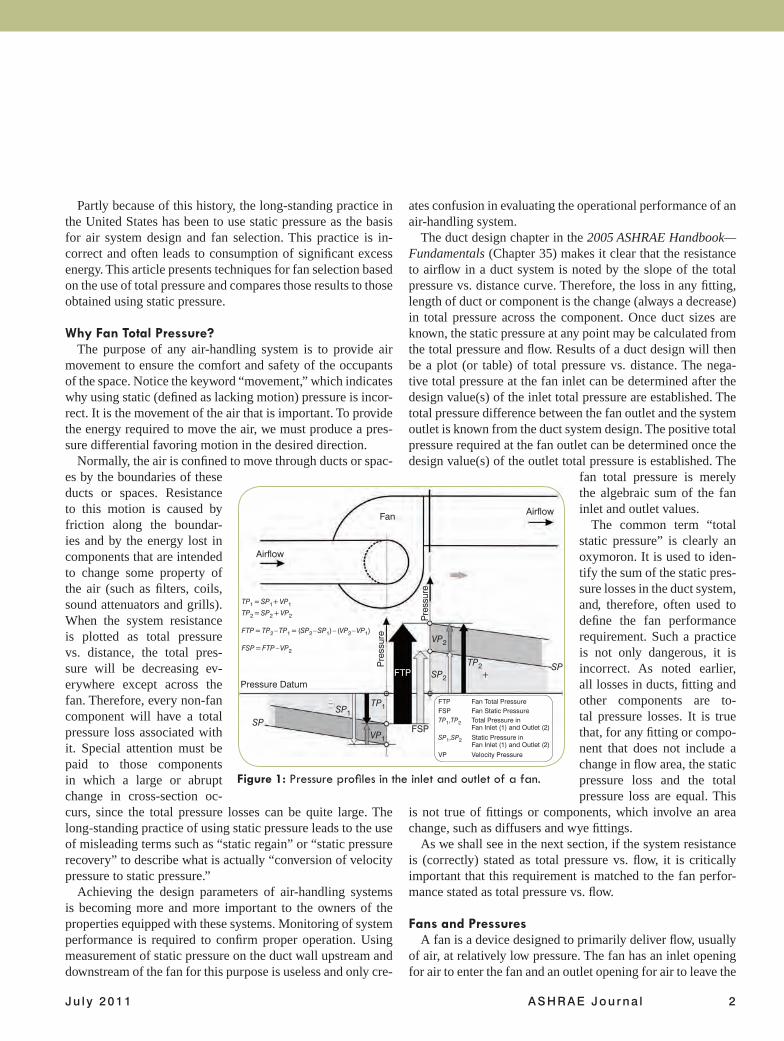
Normally, the air is confined to move through ducts or spac-es by the boundaries of these ducts or spaces. Resistance to this motion is caused by friction along the boundar-ies and by the energy lost in components that are intended to change some property of the air (such as filters, coils, sound attenuators and grills). When the system resistance is plotted as total pressure vs. distance, the total pres-sure will be decreasing ev-erywhere except across the fan. Therefore, every non-fan component will have a total pressure loss associated with it. Special attention must be paid to those components in which a large or abrupt change in cross-section oc-curs, since the total pressure losses can be quite large. The long-standing practice of using static pressure leads to the use of misleading terms such as “static regain” or “static pressure recovery” to describe what is actually “conversion of velocity pressure to static pressure.”
Achieving the design parameters of air-handling systems is becoming more and more important to the owners of the properties equipped with these systems. Monitoring of system performance is required to confirm proper operation. Using measurement of static pressure on the duct wall upstream and downstream of the fan for this purpose is useless and only cre-
ates confusion in evaluating the operational performance of an air-handling system.
The duct design chapter in the 2005 ASHRAE Handbook—Fundamentals (Chapter 35) makes it clear that the resistance to airflow in a duct system is noted by the slope of the total pressure vs. distance curve. Therefore, the loss in any fitting, length of duct or component is the change (always a decrease) in total pressure across the component. Once duct sizes are known, the static pressure at any point may be calculated from the total pressure and flow. Results of a duct design will then be a plot (or table) of total pressure vs. distance. The nega-tive total pressure at the fan inlet can be determined after the design value(s) of the inlet total pressure are established. The total pressure difference between the fan outlet and the system outlet is known from the duct system design. The positive total pressure required at the fan outlet can be determined once the design value(s) of the outlet total pressure is established. The
fan total pressure is merely the algebraic sum of the fan inlet and outlet values.
The common term “total static pressure” is clearly an oxymoron. It is used to iden-tify the sum of the static pres-sure losses in the duct system, and, therefore, often used to define the fan performance requirement. Such a practice is not only dangerous, it is incorrect. As noted earlier, all losses in ducts, fitting and other components are to-tal pressure losses. It is true that, for any fitting or compo-nent that does not include a change in flow area, the static pressure loss and the total pressure loss are equal. This
is not true of fittings or components, which involve an area change, such as diffusers and wye fittings.
As we shall see in the next section, if the system resistance is (correctly) stated as total pressure vs. flow, it is critically important that this requirement is matched to the fan perfor-mance stated as total pressure vs. flow.
Fans and PressuresA fan is a device designed to primarily deliver flow, usually
of air, at relatively low pressure. The fan has an inlet opening for air to enter the fan and an outlet opening for air to leave the
Figure 1: Pressure profiles in the inlet and outlet of a fan.
Fan
Airflow
Airflow
VP2
Pressure Datum
SPSP1
TP1
FTP
FSPVP1
SP2SPTP2
+
Pre
ssur
e
Pre
ssur
e
–
TP1 = SP1+ VP1
TP2 = SP2 + VP2
FTP = TP2 – TP1 = (SP2 – SP1) – (VP2 – VP1)
FSP = FTP – VP2
FTP Fan Total PressureFSP Fan Static PressureTP1,TP2 Total Pressure in Fan Inlet (1) and Outlet (2)
SP1,SP2 Static Pressure in Fan Inlet (1) and Outlet (2)
VP Velocity Pressure
46 AS HRAE Jou rna l ash rae .o rg J u l y 2 0 1 1
4.0
3.5
3.0
2.5
2.0
1.5
1.0
0.5
0.0
FTP
, FS
P (
in. w
.g.)
8
7
6
5
4
3
2
1
0
Fan
Po
wer
(b
hp
)
7 8 9 10 11 12 13 14 15 16
Flow (cfm in thousands)
System Curve
1,035 rpm
6.22 6.05Power
FTP
FSP
13,625
Figure 2: Fan selection made by matching the pressure drop across the system with fan static pressure.
4.0
3.5
3.0
2.5
2.0
1.5
1.0
0.5
0.0
FTP
, FS
P (
in. w
.g.)
8
7
6
5
4
3
2
1
0
Fan
Po
wer
(b
hp
)
7 8 9 10 11 12 13 14 15 16
Flow (cfm in thousands)
System Curve
989 rpm
5.29
Power
FTP
FSP
Figure 3: Fan selection made by matching the pressure drop across the system with fan total pressure.
fan. The flow through these openings is the same and creates a velocity in each of these openings. The mo-tor, usually an electromotor, delivers energy to the fan impeller and the impeller transforms the energy into the energy in the air handled by the fan.
If we define control surfaces at the inlet and outlet openings, the energy in the air delivered by the fan is the difference between the energy of the air in the outlet opening minus the energy in the air in the inlet opening of the fan. This energy has two components, static and dynamic. Since the flow is equal for both inlet and outlet, we may define the energy addition by the change in pressure between the two openings. The fan total pressure is then defined as the difference of the total pressures in the fan outlet and inlet openings.
The relations among these pressures are depicted in Figure 1, Page 45.
These pressures are defined in ISO 5801 and ANSI/AMCA Standard 210-07/ANSI/ASHRAE 51-07, Laboratory Methods of Testing Fans for Certified Aerodynamic Performance Rating. Any other terms such as total static pressure, external static pressure and external total static pressure are not defined and, therefore, should not be used.
The fan static pressure as it is defined generally cannot be measured by fan testing except for a fan having the same air velocity in its inlet and outlet openings. In such case, the fan static pressure is equal to the static pressure rise across the fan.
Using Fan Static Pressure for Fan Selection First, we must stress that the fan performance is
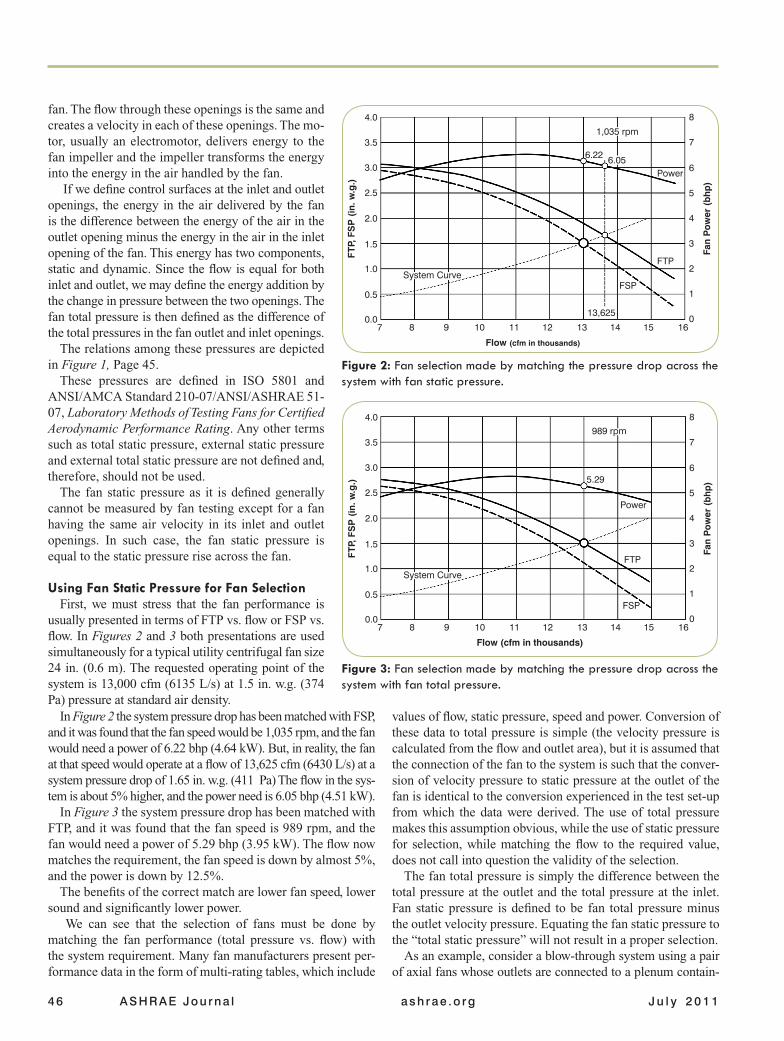
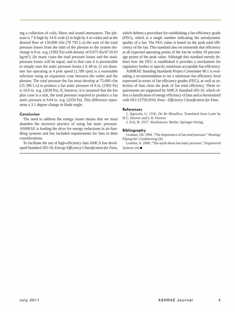
usually presented in terms of FTP vs. flow or FSP vs. flow. In Figures 2 and 3 both presentations are used simultaneously for a typical utility centrifugal fan size 24 in. (0.6 m). The requested operating point of the system is 13,000 cfm (6135 L/s) at 1.5 in. w.g. (374 Pa) pressure at standard air density.
values of flow, static pressure, speed and power. Conversion of these data to total pressure is simple (the velocity pressure is calculated from the flow and outlet area), but it is assumed that the connection of the fan to the system is such that the conver-sion of velocity pressure to static pressure at the outlet of the fan is identical to the conversion experienced in the test set-up from which the data were derived. The use of total pressure makes this assumption obvious, while the use of static pressure for selection, while matching the flow to the required value, does not call into question the validity of the selection.
The fan total pressure is simply the difference between the total pressure at the outlet and the total pressure at the inlet. Fan static pressure is defined to be fan total pressure minus the outlet velocity pressure. Equating the fan static pressure to the “total static pressure” will not result in a proper selection.
As an example, consider a blow-through system using a pair of axial fans whose outlets are connected to a plenum contain-
In Figure 2 the system pressure drop has been matched with FSP, and it was found that the fan speed would be 1,035 rpm, and the fan would need a power of 6.22 bhp (4.64 kW). But, in reality, the fan at that speed would operate at a flow of 13,625 cfm (6430 L/s) at a system pressure drop of 1.65 in. w.g. (411 Pa) The flow in the sys-tem is about 5% higher, and the power need is 6.05 bhp (4.51 kW).
In Figure 3 the system pressure drop has been matched with FTP, and it was found that the fan speed is 989 rpm, and the fan would need a power of 5.29 bhp (3.95 kW). The flow now matches the requirement, the fan speed is down by almost 5%, and the power is down by 12.5%.
The benefits of the correct match are lower fan speed, lower sound and significantly lower power.
We can see that the selection of fans must be done by matching the fan performance (total pressure vs. flow) with the system requirement. Many fan manufacturers present per-formance data in the form of multi-rating tables, which include
Ju l y 2011 ASHRAE Jou rna l 4
ing a collection of coils, filters and sound attenuators. The ple-num is 7 ft high by 14 ft wide (2 m high by 4 m wide) and at the desired flow of 150,000 cfm (70 792 L/s) the sum of the total pressure losses from the inlet of the plenum to the system dis-charge is 8 in. w.g. (1992 Pa) with density of 0.075 lbs/ft2 (0.03 kg/m2). (In many cases the total pressure losses and the static pressure losses will be equal, and in that case it is permissible to simply sum the static pressure losses.) A 48 in. (1 m) diam-eter fan operating at 4 pole speed (1,780 rpm) is a reasonable selection using an expansion cone between the outlet and the plenum. The total pressure the fan must develop at 75,000 cfm (35 396 L/s) to produce a fan static pressure of 8 in. (1992 Pa) is 10.6 in. w.g. (2639 Pa). If, however, it is assumed that the fan plus cone is a unit, the total pressure required to produce a fan static pressure is 9.04 in. w.g. (2250 Pa). This difference repre-sents a 3.1 degree change in blade angle.
ConclusionThe need to address the energy issues means that we must
abandon the incorrect practice of using fan static pressure. ASHRAE is leading the drive for energy reductions in air-han-dling systems and has included requirements for fans in their considerations.
To facilitate the use of high-efficiency fans AMCA has devel-oped Standard 205-10, Energy Efficiency Classification for Fans,
which defines a procedure for establishing a fan efficiency grade (FEG), which is a single number indicating the aerodynamic quality of a fan. The FEG value is based on the peak total effi-ciency of the fan. This standard also recommends that efficiency at all expected operating points of the fan be within 10 percent-age points of the peak value. Although this standard merely de-fines how the FEG is established it provides a mechanism for regulatory bodies to specify minimum acceptable fan efficiency.
ASHRAE Standing Standards Project Committee 90.1 is eval-uating a recommendation to set a minimum fan efficiency level expressed in terms of fan efficiency grades (FEG), as well as se-lection of fans close the peak of fan total efficiency. These re-quirements are supported by AMCA Standard 205-10, which of-fers a classification of energy efficiency of fans and is harmonized with ISO 12759:2010, Fans—Efficiency Classification for Fans.
References1. Agricola, G. 1556. De Re Metallica. Translated from Latin by
H.C. Hoover and L.H. Hoover. 2. Eck, B. 1937. Ventilatoren. Berlin: Springer-Verlag.
BibliographyGraham, J.B. 1994. “The importance of fan total pressure.” Heating/
Piping/Air Conditioning (9).London, A. 2006. “The myth about fan static pressure.” Engineered
Systems (4).
AMCA AD WILL GO HEREDelete Page and Replace