resistor color code. lesson 2 theory (30 minutes) workstation (30 minutes) –measure resistance...
TRANSCRIPT
Resistor Color Code
Lesson 2
• Theory (30 minutes)
• WorkStation (30 minutes)– Measure Resistance color
• Revision (30 minutes)
• Break
• Individual Exercise (1 hour)
04/18/23 TT 2
Lesson 2
• Correction of Exercise (30 minutes)
• Theory on Parallel Circuit – Current– Voltage– Resistor
• Exercise
04/18/23 TT 3
04/18/23 TT 4
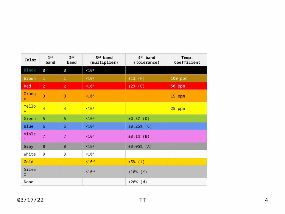
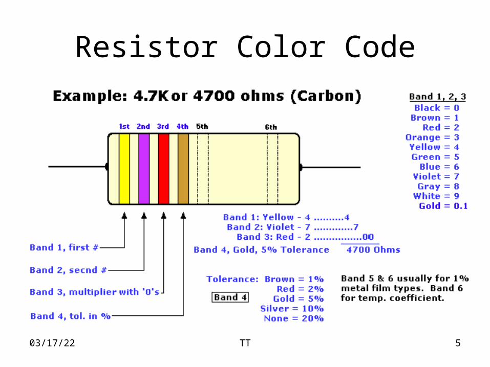
Color 1st band 2nd band 3rd band (multiplier) 4th band (tolerance) Temp. Coefficient
Black 0 0 ×100
Brown 1 1 ×101 ±1% (F) 100 ppm
Red 2 2 ×10² ±2% (G) 50 ppm
Orange 3 3 ×10³ 15 ppm
Yellow 4 4 ×10⁴ 25 ppm
Green 5 5 ×10⁵ ±0.5% (D)
Blue 6 6 ×10⁶ ±0.25% (C)
Violet 7 7 ×10⁷ ±0.1% (B)
Gray 8 8 ×10⁸ ±0.05% (A)
White 9 9 ×10⁹
Gold ×10-1 ±5% (J)
Silver ×10-2 ±10% (K)
None ±20% (M)
04/18/23 TT 5
Resistor Color Code
04/18/23 TT 6
Resistor Color Code (cont’d)
• Another example for a Carbon 22000 Ohms or 22 Kilo-Ohms also known as 22K at 5% tolerance:
Band 1 = Red, 1st digitBand 2 = Red, 2nd digitBand 3 = Orange, 3rd digit, multiply with zeros, in this case 3 zero'sBand 4 = Gold, Tolerance, 5%
04/18/23 TT 7
Resistor Color Code (cont’d)
• Try the steps below to help you 'Learn the Color-code'.
• Make sure you add the number to the color, like: 0 is black, 1 is brown, 2 is red, etc. etc.
• Do not proceed to step 3 until you know the color-code backwards, forwards, and inside-and-out (trust me!)
04/18/23 TT 8
Resistor Color Code (cont’d)
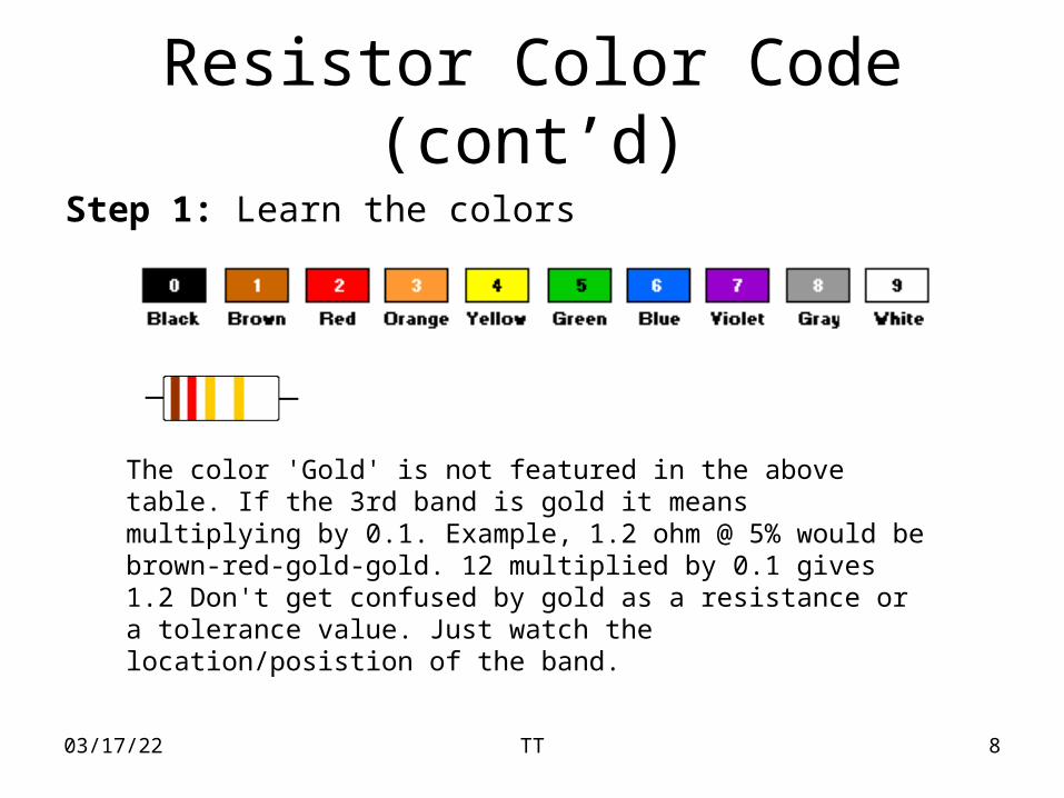
Step 1: Learn the colors
The color 'Gold' is not featured in the above table. If the 3rd band is gold it means multiplying by 0.1. Example, 1.2 ohm @ 5% would be brown-red-gold-gold. 12 multiplied by 0.1 gives 1.2 Don't get confused by gold as a resistance or a tolerance value. Just watch the location/posistion of the band.
04/18/23 TT 9
Resistor Color Code (cont’d)
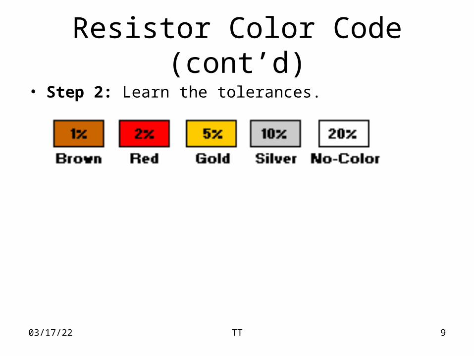
• Step 2: Learn the tolerances.

04/18/23 TT 10
Resistor Color Code (cont’d)
• Do the exercises below.
Colors used for 'Gold, Orange, Gray, and Silver‘
1st band: Brown (1)2nd band: Black (0)3rd band, how many zeros (1)4th band, tolerance in %: gold (5)Answer: 1 0 1 = 100 ohm, 5% tolerance
04/18/23 TT 11
Resistor Color Code (cont’d)
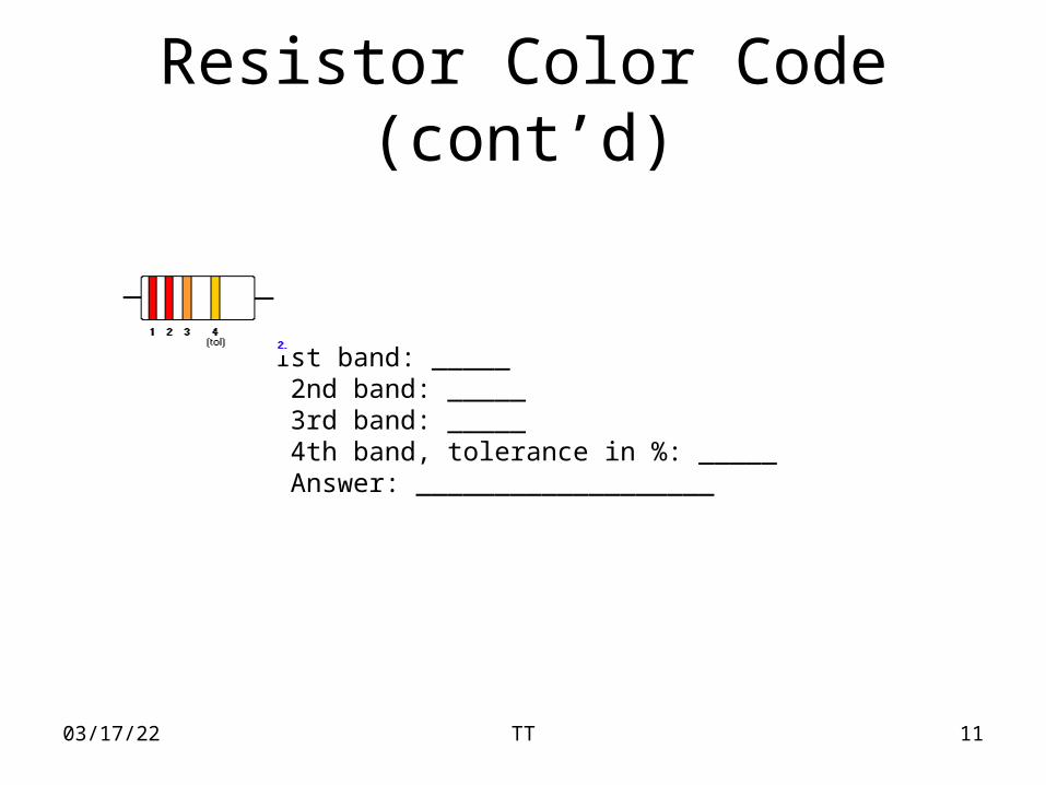
1st band: _____ 2nd band: _____ 3rd band: _____ 4th band, tolerance in %: _____ Answer: ___________________
04/18/23 TT 12
Resistor Color Code (cont’d)
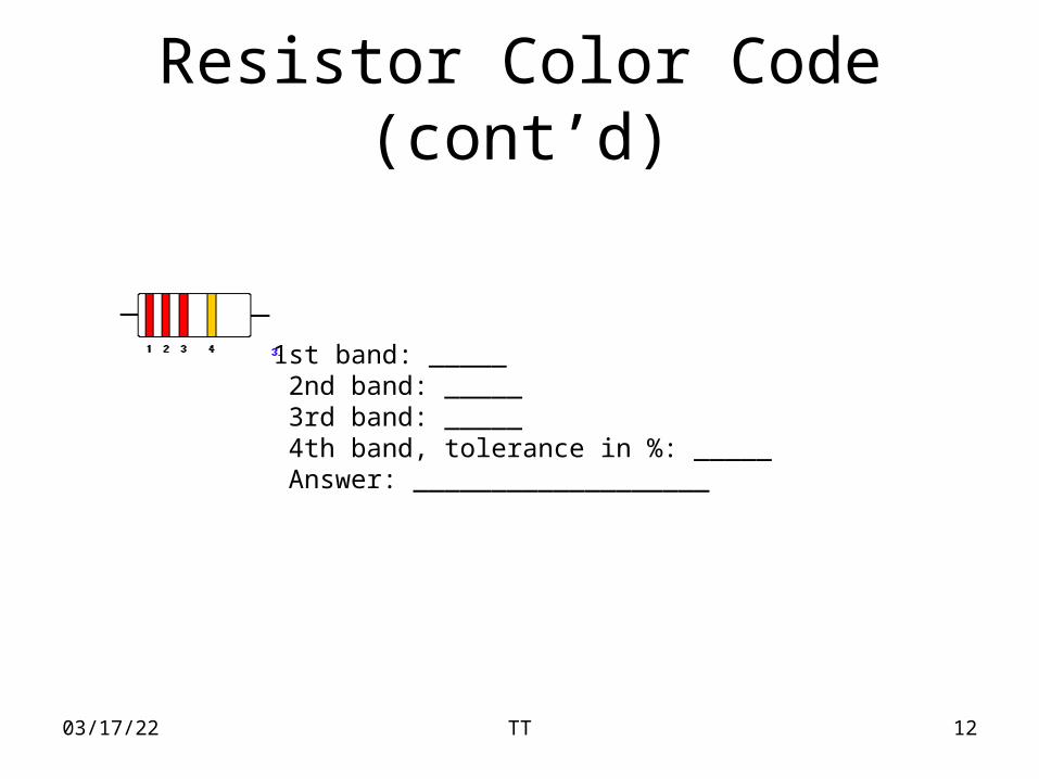
1st band: _____ 2nd band: _____ 3rd band: _____ 4th band, tolerance in %: _____ Answer: ___________________
04/18/23 TT 13
Resistor Color Code (cont’d)
1st band: _____ 2nd band: _____ 3rd band: _____ 4th band, tolerance in %: _____ Answer: ___________________
04/18/23 TT 14
Resistor Color Code (cont’d)
Here are some mnemonics that you might find less offensive (than one you may have seen):
•Buffalo Bill Roamed Over Yellow Grass Because Vistas Grand Were God's Sanctuary
•Bully Brown Ran Over a Yodeling Goat, Because Violet's Granny Was Gone Snorkeling
04/18/23 TT 15
Building Simple Resistor Circuits
• In the course of learning about electricity, you will want to construct your own circuits using resistors and batteries. Some options are available in this matter of circuit assembly, some easier than others. In this section, we will explore a couple of fabrication techniques that will not only help you build the circuits shown in this chapter, but also more advanced circuits.
04/18/23 TT 16
Building Simple Resistor Circuits (cont’d)
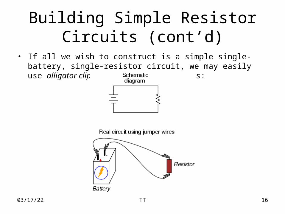
• If all we wish to construct is a simple single-battery, single-resistor circuit, we may easily use alligator clip jumper wires like this:
04/18/23 TT 17
Building Simple Resistor Circuits (cont’d)
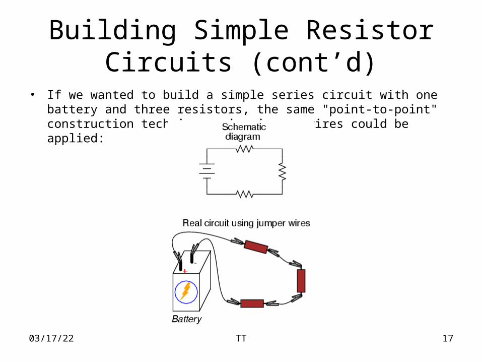
• If we wanted to build a simple series circuit with one battery and three resistors, the same "point-to-point" construction technique using jumper wires could be applied:
04/18/23 TT 18
Building Simple Resistor Circuits (cont’d)
• This technique, however, proves impractical for circuits much more complex than this, due to the awkwardness of the jumper wires and the physical fragility of their connections. A more common method of temporary construction for the hobbyist is the solderless breadboard, a device made of plastic with hundreds of spring-loaded connection sockets joining the inserted ends of components and/or 22-gauge solid wire pieces.
04/18/23 TT 19
Building Simple Resistor Circuits (cont’d)
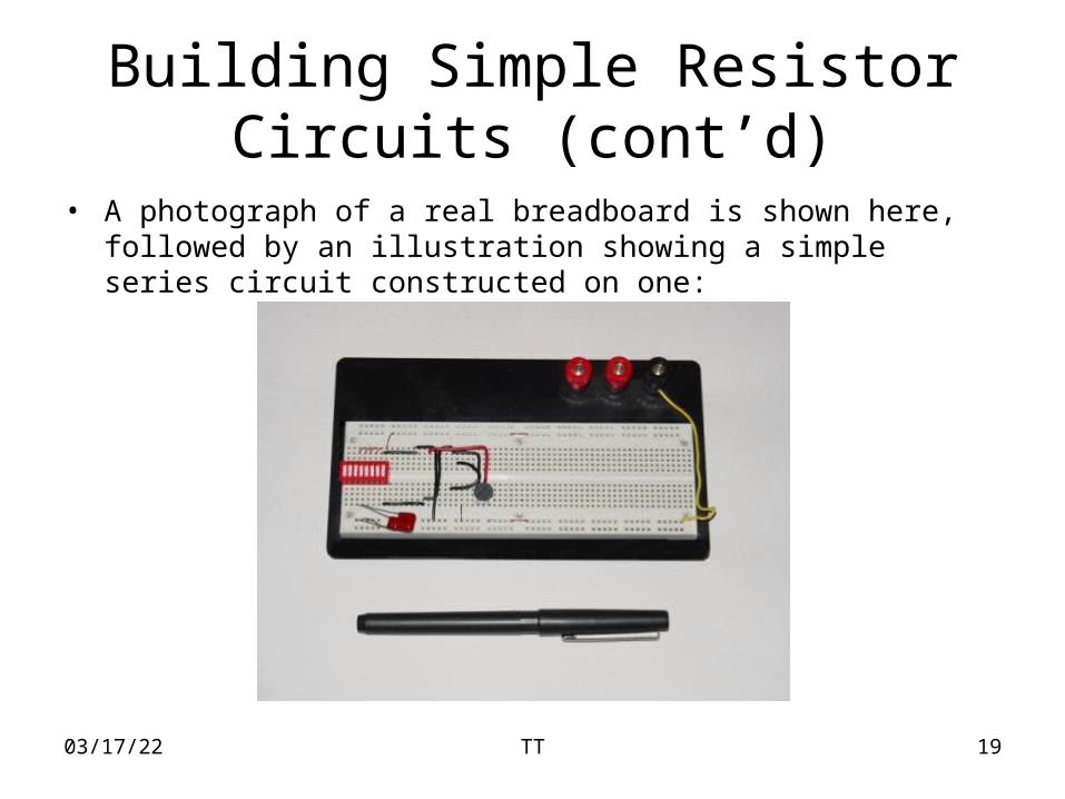
• A photograph of a real breadboard is shown here, followed by an illustration showing a simple series circuit constructed on one:
04/18/23 TT 20
Building Simple Resistor Circuits (cont’d)
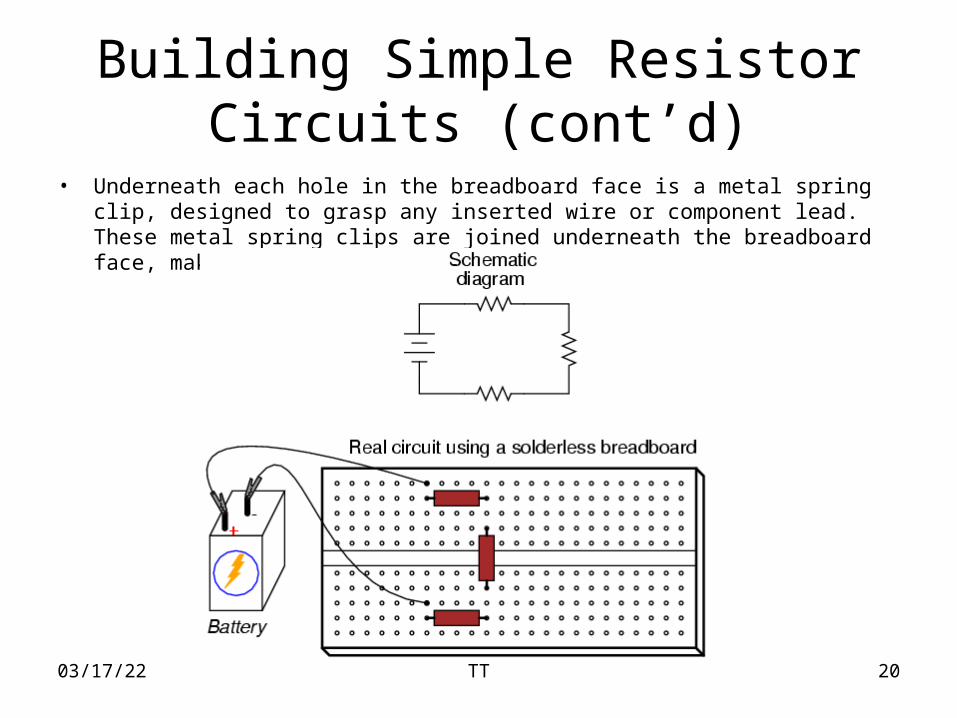
• Underneath each hole in the breadboard face is a metal spring clip, designed to grasp any inserted wire or component lead. These metal spring clips are joined underneath the breadboard face, making connections between inserted leads.
04/18/23 TT 21
Building Simple Resistor Circuits (cont’d)
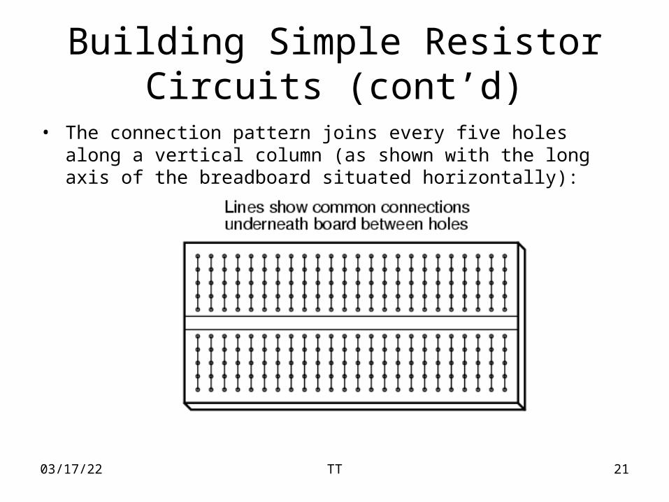
• The connection pattern joins every five holes along a vertical column (as shown with the long axis of the breadboard situated horizontally):
04/18/23 TT 22
Building Simple Resistor Circuits (cont’d)
• Thus, when a wire or component lead is inserted into a hole on the breadboard, there are four more holes in that column providing potential connection points to other wires and/or component leads. The result is an extremely flexible platform for constructing temporary circuits.
04/18/23 TT 23
Building Simple Resistor Circuits (cont’d)
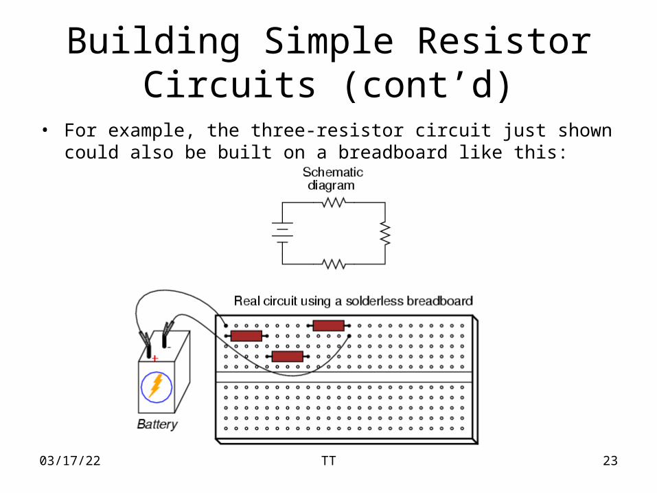
• For example, the three-resistor circuit just shown could also be built on a breadboard like this:

04/18/23 TT 24
Building Simple Resistor Circuits (cont’d)
• A parallel circuit is also easy to construct on a solderless breadboard:
04/18/23 TT 25
Building Simple Resistor Circuits (cont’d)
• REVIEW:
• A solderless breadboard is a device used to quickly assemble temporary circuits by plugging wires and components into electrically common spring-clips arranged underneath rows of holes in a plastic board.