residential gas water heaters - hot water · residential gas water heaters installation and...
TRANSCRIPT
1404 326940-001
RESIDENTIAL GAS WATER HEATERSInstallation and Operating Manual
KEEP THIS MANUAL IN THE POCKET ON HEATER FOR FUTURE REFERENCEWHENEVER MAINTENANCE ADJUSTMENT OR SERVICE IS REQUIRED.
DIRECT VENTED GAS MODELSNOT FOR USE IN MANUFACTURED (MOBILE) HOMES
• For Your Safety •AN ODO RANT IS ADDED TO THE GAS USED
BY THIS WATER HEATER.
ALL TECHNICAL AND WARRANTY QUESTIONS: SHOULD BE DIRECTED TO THE LOCAL DEALER FROM WHOM THE WATER HEATER WAS PURCHASED. IF YOU ARE UNSUCCESSFUL, PLEASE CONTACT THE COMPANY LISTED ON THE RATING PLATE ON THE WATER HEATER.
www.hotwater.com
2 www. hotwater .com
TABLE OF CONTENTSSAFE INSTALLATION, USE AND SERVICE . . . . . . . . . . . 3GENERAL SAFETY . . . . . . . . . . . . . . . . . . . . . . . . . . . . . . 4INTRODUCTION . . . . . . . . . . . . . . . . . . . . . . . . . . . . . . . . 6 Qualifi ed Installer Or Service Agency . . . . . . . . . . . . 6 Preparing For The Installation. . . . . . . . . . . . . . . . . . 6INSTALLATION REQUIREMENTS FOR THE COMMONWEALTH OF MASSACHUSETTS. . . . . . . . . . . 7TYPICAL INSTALLATION. . . . . . . . . . . . . . . . . . . . . . . . . . 9 Get To Know Your Water Heater - Gas Models
(List Referencing Figures 1-5). . . . . . . . . . . . . . . . . . 9 Replacement Parts And Deliming Products . . . . . . 10 Combo Heating Inlet And Outlet Side Taps. . . . . . . 10 High Limit Controls (Energy Cut Off). . . . . . . . . . . . 10 Thermostat/Water TemperatureLOCATING THE NEW WATER HEATER. . . . . . . . . . . . . 11 Facts To Consider About The Location . . . . . . . . . . .11 External/Internal Damage . . . . . . . . . . . . . . . . . . . . .11 Air Requirements . . . . . . . . . . . . . . . . . . . . . . . . . . 12 Confi ned Space Installations. . . . . . . . . . . . . . . . . . 12 Clearances To Combustibles Floors With Carpeting Clearance For Servicing Chemical Vapor Corrosion . . . . . . . . . . . . . . . . . . . 12 Storage Of Flammable Liquids . . . . . . . . . . . . . . . . 13 Insulation Blankets . . . . . . . . . . . . . . . . . . . . . . . . . 13 Water Piping . . . . . . . . . . . . . . . . . . . . . . . . . . . . . . 14 Water Pressure Mixing ValvesINSTALLING THE NEW WATER HEATER . . . . . . . . . . .15 Water Piping Installation . . . . . . . . . . . . . . . . . . . . . 15 Closed Water Systems . . . . . . . . . . . . . . . . . . . . . . 15 Thermal Expansion . . . . . . . . . . . . . . . . . . . . . . . . . 15 Temperature-Pressure Relief Valve. . . . . . . . . . . . . 16 T&P Valve Discharge Pipe Requirements: Temperature-Pressure Relief Valve And
Pipe Insulation Filling The Water Heater . . . . . . . . . . . . . . . . . . . . . 17 Space Heating And Potable Water Systems . . . . . . 18 Combo Heating . . . . . . . . . . . . . . . . . . . . . . . . . . . . 19 System Requirements Installation Gas Piping. . . . . . . . . . . . . . . . . . . . . . . . . . . . . . . . 20 Sediment Trap. . . . . . . . . . . . . . . . . . . . . . . . . . . . . 21 High Altitude Installations . . . . . . . . . . . . . . . . . . . . 21 Venting . . . . . . . . . . . . . . . . . . . . . . . . . . . . . . . . . . 22 Vent Terminal Clearances . . . . . . . . . . . . . . . . . . . . 22 DV Termination Safety Cover . . . . . . . . . . . . . . . . . 23 Vent Connections . . . . . . . . . . . . . . . . . . . . . . . . . . 23 Locating Clearance Hole For Vent . . . . . . . . . . . . . 23 Standard Vent Arrangement . . . . . . . . . . . . . . . . . . 23 Vent Assembly. . . . . . . . . . . . . . . . . . . . . . . . . . . . . 24 Securing Vent Termination Assembly To
The Exterior Wall. . . . . . . . . . . . . . . . . . . . . . . . . . . 24 Vent Restricter Plate . . . . . . . . . . . . . . . . . . . . . . . . 24 Uncompressing The Corrugated Tubing . . . . . . . . . 24 Vent Connection To The Water Heater . . . . . . . . . . 25 Offset Vent Arrangement . . . . . . . . . . . . . . . . . . . . . 25 Installation Checklist . . . . . . . . . . . . . . . . . . . . . . . . 27
LIGHTING INSTRUCTIONS. . . . . . . . . . . . . . . . . . . . . . .28TEMPERATURE REGULATION . . . . . . . . . . . . . . . . . . .29 Temperature Regulation . . . . . . . . . . . . . . . . . . . . . 29 Temperature Adjustment Operating The Temperature Control System. . . . . . 29 Water Temperature Adjustment Operating Modes And SettingsFOR YOUR INFORMATION. . . . . . . . . . . . . . . . . . . . . . .30 External Damage . . . . . . . . . . . . . . . . . . . . . . . . . . 30 Start Up Conditions . . . . . . . . . . . . . . . . . . . . . . . . . 30 Condensate Smoke/Odor Thermal Expansion . . . . . . . . . . . . . . . . . . . . . . . . . 30 Strange Sounds . . . . . . . . . . . . . . . . . . . . . . . . . . . 31 Operational Conditions . . . . . . . . . . . . . . . . . . . . . . 31 Smelly Water “Air” In Hot Water Faucets High Water Temperature Shut Off SystemMAINTENANCE . . . . . . . . . . . . . . . . . . . . . . . . . . . . . . . .32 Housekeeping . . . . . . . . . . . . . . . . . . . . . . . . . . . . . 32 Flood Damage. . . . . . . . . . . . . . . . . . . . . . . . . . . . . 32 Venting System Inspection . . . . . . . . . . . . . . . . . . . 32 Pilot And Main Burner . . . . . . . . . . . . . . . . . . . . . . . 32 Burner Flames. . . . . . . . . . . . . . . . . . . . . . . . . . . . . 33 Servicing The Water Heater . . . . . . . . . . . . . . . . . . 33 Removing And Replacing The Gas Control Valve/
Thermostat . . . . . . . . . . . . . . . . . . . . . . . . . . . . . . . 33 Removing The Gas Control Valve/Thermostat: Replacing The Gas Control Valve/Thermostat: Removing The Manifold/Burner Assembly . . . . . . . 33 Removing The Burner From The Manifold/Burner
Assembly. . . . . . . . . . . . . . . . . . . . . . . . . . . . . . . . . 34 Natural Gas (Low Nox) & Propane (LP) Gas Burner Replacing The Pilot/Thermopile Assembly . . . . . . . 34 Replacing The Manifold/Burner Assembly . . . . . . . 35 Piezoelectric Igniter System . . . . . . . . . . . . . . . . . . 36 Testing The Igniter System . . . . . . . . . . . . . . . . . . . 36 Temperature-Pressure Relief Valve Test . . . . . . . . . 36 Draining, Refi lling And Flushing . . . . . . . . . . . . . . . 36 To Drain The Water Heater Storage Tank To Refi ll The Water Heater Storage Tank To Flush The Water Heater Storage Tank Drain Valve Washer Replacement . . . . . . . . . . . . . 37 Anode Rod Maintenance. . . . . . . . . . . . . . . . . . . . . 37 To Remove The Anode Rod: To Install The Anode Rod:LEAKAGE CHECKPOINTS . . . . . . . . . . . . . . . . . . . . . . .39 Service . . . . . . . . . . . . . . . . . . . . . . . . . . . . . . . . . . 39REFERENCE PARTS LISTING . . . . . . . . . . . . . . . . . . . .40TROUBLESHOOTING GUIDELINES. . . . . . . . . . . . . . . .42NOTES . . . . . . . . . . . . . . . . . . . . . . . . . . . . . . . . . . . . . . .46
www. hotwater .com 3
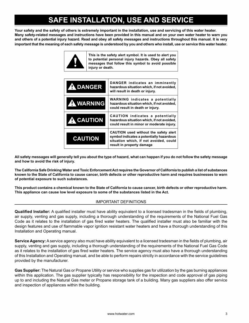
SAFE INSTALLATION, USE AND SERVICEYour safety and the safety of others is extremely important in the installation, use and servicing of this water heater.Many safety-related messages and instructions have been provided in this manual and on your own water heater to warn you and others of a potential injury hazard. Read and obey all safety messages and instructions throughout this manual. It is very important that the meaning of each safety message is understood by you and others who install, use or service this water heater.
This is the safety alert symbol. It is used to alert you to potential personal injury hazards. Obey all safety messages that follow this symbol to avoid possible injury or death.
CAUTION used without the safety alert symbol indicates a potentially hazardous situation which, if not avoided, could result in property damage
CAUTION indicates a potential ly hazardous situation which, if not avoided, could result in minor or moderate injury.
WARNING indicates a potential ly hazardous situation which, if not avoided, could result in death or injury.
DANGER indicates an imminently hazardous situation which, if not avoided, will result in death or injury.
CAUTION
WARNING
CAUTION
DANGER
All safety messages will generally tell you about the type of hazard, what can happen if you do not follow the safety message and how to avoid the risk of injury.
The California Safe Drinking Water and Toxic Enforcement Act requires the Governor of California to publish a list of substances known to the State of California to cause cancer, birth defects or other reproductive harm and requires businesses to warn of potential exposure to such substances.
This product contains a chemical known to the State of California to cause cancer, birth defects or other reproductive harm. This appliance can cause low level exposure to some of the substances listed in the Act.
IMPORTANT DEFINITIONS
Qualifi ed Installer: A qualifi ed installer must have ability equivalent to a licensed tradesman in the fi elds of plumbing, air supply, venting and gas supply, including a thorough understanding of the requirements of the National Fuel Gas Code as it relates to the installation of gas fi red water heaters. The qualifi ed installer must also be familiar with the design features and use of fl ammable vapor ignition resistant water heaters and have a thorough understanding of this Installation and Operating manual.
Service Agency: A service agency also must have ability equivalent to a licensed tradesman in the fi elds of plumbing, air supply, venting and gas supply, including a thorough understanding of the requirements of the National Fuel Gas Code as it relates to the installation of gas fi red water heaters. The service agency must also have a thorough understanding of this Installation and Operating manual, and be able to perform repairs strictly in accordance with the service guidelines provided by the manufacturer.
Gas Supplier: The Natural Gas or Propane Utility or service who supplies gas for utilization by the gas burning appliances within this application. The gas supplier typically has responsibility for the inspection and code approval of gas piping up to and including the Natural Gas meter or Propane storage tank of a building. Many gas suppliers also offer service and inspection of appliances within the building.
4 www. hotwater .com
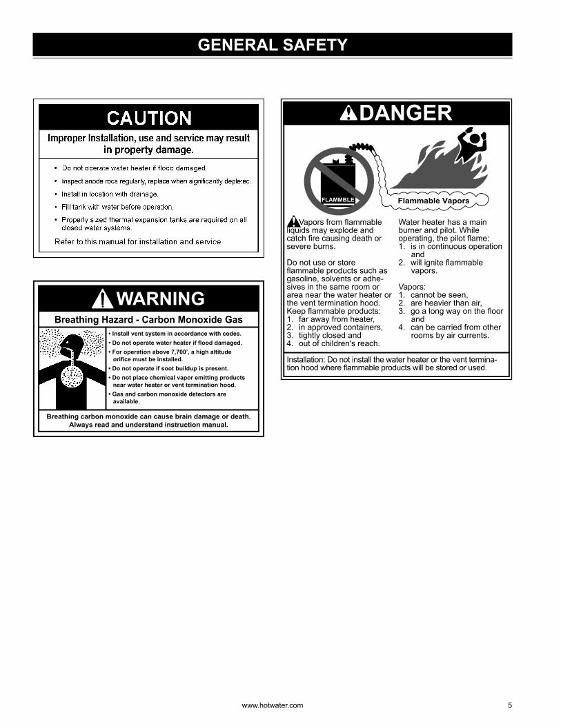
GENERAL SAFETY
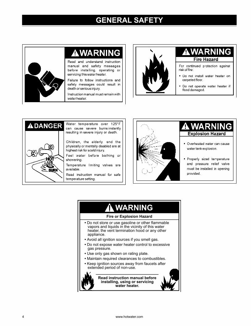
Read instruction manual before installing, using or servicing
water heater.
• Do not store or use gasoline or other flammable vapors and liquids in the vicinity of this water heater, the vent termination hood or any other appliance.
• Avoid all ignition sources if you smell gas.• Do not expose water heater control to excessive
gas pressure.• Use only gas shown on rating plate.• Maintain required clearances to combustibles.• Keep ignition sources away from faucets after
extended period of non-use.
Fire or Explosion Hazard
WARNING
www. hotwater .com 5
GENERAL SAFETY
Breathing carbon monoxide can cause brain damage or death.Always read and understand instruction manual.
• Install vent system in accordance with codes.• Do not operate water heater if flood damaged.• For operation above 7,700’, a high altitude
orifice must be installed.• Do not operate if soot buildup is present.• Do not place chemical vapor emitting products
near water heater or vent termination hood.• Gas and carbon monoxide detectors are
available.
Breathing Hazard - Carbon Monoxide Gas
WARNING
Installation: Do not install the water heater or the vent termina-tion hood where flammable products will be stored or used.
Vapors from flammable liquids may explode and catch fire causing death or severe burns.
Do not use or store flammable products such as gasoline, solvents or adhe-sives in the same room or area near the water heater or the vent termination hood.Keep flammable products:1. far away from heater,2. in approved containers,3. tightly closed and4. out of children's reach.
Water heater has a main burner and pilot. While operating, the pilot flame:1. is in continuous operation
and2. will ignite flammable
vapors.
Vapors:1. cannot be seen,2. are heavier than air,3. go a long way on the floor
and4. can be carried from other
rooms by air currents.
Flammable VaporsFLAMMBLE
DANGER
6 www. hotwater .com
INTRODUCTIONThank You for purchasing this water heater. Properly installed and maintained, it should give you years of trouble free service.This water heater is suitable for potable water heating and space heating applications but not for space heating only applications.
Abbreviations found in this Installation and Operating manual:• CSA - Canadian Standards Association• ANSI - American National Standards Institute• NFPA - National Fire Protection Association• ASME - American Society of Mechanical Engineers• UL - Underwriters Laboratories Inc.• AHRI - Air Conditioning, Heating and Refrigeration
Institute.
This gas-fi red water heater is design certifi ed by CSA International, under Water Heater Standard ANSI Z21.10.1 • CSA 4.1 (current edition).
QUALIFIED INSTALLER OR SERVICE AGENCYInstallation and service of this water heater requires ability equivalent to that of a Qualifi ed Agency (as defi ned by ANSI below) in the fi eld involved. Installation skills such as plumbing, air supply, venting, gas supply and electrical supply are required in addition to electrical testing skills when performing service.
ANSI Z223.1 2006 Sec. 3.3.83: “Qualifi ed Agency” - “Any individual, fi rm, corporation or company that either in person or through a representative is engaged in and is responsible for (a) the installation, testing or replacement of gas piping or (b) the connection, installation, testing, repair or servicing of appliances and equipment; that is experienced in such work; that is familiar with all precautions required and that has complied with all the requirements of the authority having jurisdiction.”
If you are not qualifi ed (as defi ned by ANSI above) and licensed or certified as required by authority having jurisdiction to perform a given task, do not attempt to perform any of the procedures described in this manual. If you do not understand the instructions given in this manual do not attempt to perform any procedures outlined in this manual.
PREPARING FOR THE INSTALLATION1. Read the “General Safety” section of this manual
fi rst and then entire manual carefully. If you don’t follow safety rules, the water heater will not operate properly. It could cause DEATH, SERIOUS BODILY INJURY AND/OR PROPERTY DAMAGE. This manual contains instructions for installation, operation, and maintenance of the gas-fi red water heater. It
also contains warnings throughout the manual that you must read and be aware of. All warnings and instructions are essential to proper operation of the water heater and your safety. Since we cannot put everything on the fi rst few pages, READ ENTIRE MANUAL BEFORE ATTEMPTING TO INSTALL OR OPERATE THE WATER HEATER.
2. The installation must conform with these instructions and local code authority having jurisdiction. In absence of local codes, installation must comply with current editions of the “National Fuel Gas Code”, ANSI Z223.1/NFPA 54 and “National Electrical Code”, NFPA 70. All documents are available from:
CSA International,8501 East Pleasant Valley Road,Cleveland, Ohio, United States44131-5575.
NFPA documents are also available from:National Fire Protection Association,1 Batterymarch Park,Quincy, MA 02269.
3. If after reading this manual you have any questions or do not understand any portion of the instructions, call the local gas utility or the manufacturer whose name appears on the rating plate.
4. Carefully plan the place where you are going to put the water heater. Correct combustion, vent action, and vent pipe installation are very important in preventing death from possible carbon monoxide poisoning and fi res (see Figure 6). Examine the location to ensure the water heater complies with the “Locating The New Water Heater” section in this manual.
5. NOTE: For California installation , this water heater must be braced, anchored, or strapped to avoid falling or moving during an earthquake. Correct installation procedure instructions may be obtained from:
California’s Offi ce of the State Architect,1102 Q Street, Suite 5100,Sacramento, CA 95811.Instructions can also be downloaded to your computer at www.dsa.dgs.ca.gov..
6. Massachusetts Code requires this water heater to be installed In accordance with Massachusetts 248-CMR 2.00: State Plumbing Code and 248-CMR 5.00.
7. This product is certifi ed to comply with a maximum weighted average of 0.25% lead content as required in some areas.
www. hotwater .com 7
INSTALLATION REQUIREMENTS FOR THE COMMONWEALTH OF MASSACHUSETTS
COMMONWEALTH OF MASSACHUSETTSFor all side wall terminated, horizontally vented power vent, direct vent and power direct vent gas fueled water heaters installed in every dwelling, building or structure used in whole or in part for residential purposes, including those owned or operated by the Commonwealth and where the side wall exhaust vent termination is less than seven (7) feet above fi nished grade in the area of the venting, including but not limited to decks and porches, the following requirements shall be satisfi ed:
INSTALLATION OF CARBON MONOXIDE DETECTORSAt the time of installation of the side wall horizontal vented gas fueled equipment, the installing plumber or gasfi tter shall observe that a hard wired carbon monoxide detector with an alarm and battery back-up is installed on the fl oor level where the gas equipment is to be installed. In addition, the installing plumber or gasfi tter shall observe that a battery operated or hard wired carbon monoxide detector with an alarm is installed on each additional level of the dwelling, building or structure served by the sidewall horizontal vented gas fueled equipment. It shall be the responsibility of the property owner to secure the services of qualifi ed licensed professionals for the installation of hard wired carbon monoxide detectors.In the event that the side wall horizontally vented gas fueled equipment is installed in a crawl space or an attic, the hard wired carbon monoxide detector with alarm and battery back-up may be installed on the next adjacent fl oor level.In the event that the requirements of this subdivision can not be met at the time of completion of installation, the owner shall have a period of thirty (30) days to comply with the above requirements provided that during said thirty (30) day period, a battery operated carbon monoxide detector with an alarm shall be installed.
APPROVED CARBON MONOXIDE DETECTORSEach carbon monoxide detector as required in accordance with the above provisions shall comply with NFPA 720 and be ANSI/ UL 2034 listed and CSA certifi ed.
SIGNAGEA metal or plastic identifi cation plate shall be permanently mounted to the exterior of the building at a minimum height of eight (8) feet above grade directly in line with the exhaust vent terminal for the horizontally vented gas fueled heating appliance or equipment. The sign shall read, in print size no less than one- half (1/2) inch in size, “GAS VENT DIRECTLY BELOW. KEEP CLEAR OF ALL OBSTRUCTIONS.”
INSPECTIONThe state or local gas inspector of the side wall horizontally vented gas fueled equipment shall not approve the installation unless, upon inspection, the inspector observes carbon monoxide detectors and signage installed in accordance with the provisions of 248 CMR 5.08(2)(a) 1 through 4.
EXEMPTIONSThe following equipment is exempt from 248 CMR 5.08(2) (a) 1 through 4:1. The equipment listed in Chapter 10 entitled “Equipment Not Required To Be Vented” in the most current edition of
NFPA 54 as adopted by the Board; and2. Product Approved side wall horizontally vented gas fueled equipment installed in a room or structure separate from
the dwelling, building, or structure used in whole or in part for residential purposes.
MANUFACTURER REQUIREMENTS - GAS EQUIPMENT VENTING SYSTEM PROVIDEDWhen the manufacturer of Product Approved side wall horizontally vented gas equipment provides a venting system design or venting system components with the equipment, the instructions provided by the manufacturer for installation of the equipment and the venting system shall include:1. Detailed instructions for the installation of the venting system design or the venting system components; and2. A complete parts list for the venting system design or venting system.
MANUFACTURER REQUIREMENTS - GAS EQUIPMENT VENTING SYSTEM NOT PROVIDEDWhen the manufacturer of Product Approved side wall horizontally vented gas fueled equipment does not provide the parts for venting the fl ue gases, but identifi es “special venting systems,” the following requirements shall be satisfi ed by the manufacturer:1. The referenced “special venting system” instructions shall be included with the appliance or equipment installation
instructions; and2. The “special venting systems” shall be Product Approved by the Board, and the instructions for that system shall
include a parts list and detailed installation instructions.A copy of all installation instructions for all Product Approved side wall horizontally vented gas fueled equipment, all venting instructions, all parts lists for venting instructions, and/or all venting design instructions shall remain with the appliance or equipment at the completion of the installation.
8 www. hotwater .com
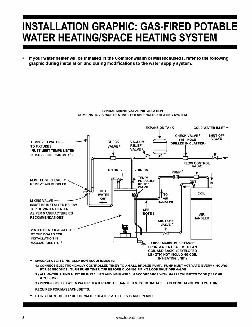
• If your water heater will be installed in the Commonwealth of Massachusetts, refer to the following graphic during installation and during modifications to the water supply system.
INREMOVE AMUST BE VERTICAL TO
IR BUBBLES
E
OUT
COIL
AIRHANDLER
TOAIR
HANDLER
SHUT-OFFVALVE *
EXPANSION TANK
VACUUMRELIEFVALVE
COLD WATER INLET
VAFLOW CONTROL
LV
PUMP *
SHUT-OFFCHECK VALVE †
(1/8” HOLE DRILLED IN CLAPPER)
VALVECHECK
VALVE †
TEMP/PRESSURERELIEFVALVE
TEMPERED WATERTO FIXTURES(MUST MEET TEMPS LISTED IN MASS. CODE 248 CMR † )
MIXING VALVE(MUST BE INSTALLED BELOW TOP OF WATER HEATERAS PER MANUFACTURER’S RECOMMENDATIONS)
UNION UNION
HOTWATER
OUT
* MASSACHUSETTS INSTALLATION REQUIREMENTS: 1.) CONNECT ELECTRONICALLY-CONTROLLED TIMER TO AN ALL-BRONZE PUMP. PUMP MUST ACTIVATE EVERY 6 HOURS
FOR 60 SECONDS. TURN PUMP TIMER OFF BEFORE CLOSING PIPING LOOP SHUT-OFF VALVE. 2.) ALL WATER PIPING MUST BE INSTALLED AND INSULATED IN ACCORDANCE WITH MASSACHUSETTS CODE (248 CMR
& 780 CMR). 3.) PIPING LOOP BETWEEN WATER HEATER AND AIR HANDLER MUST BE INSTALLED IN COMPLIANCE WITH 248 CMR.
† REQUIRED FOR MASSACHUSETTS.
‡ PIPING FROM THE TOP OF THE WATER HEATER WITH TEES IS ACCEPTABLE.
WATER HEATER ACCEPTED BY THE BOARD FOR INSTALLATION IN MASSACHUSETTS. †
TYPICAL MIXING VALVE INSTALLATION COMBINATION SPACE HEATING / POTABLE WATER HEATING SYSTEM
SEENOTE ‡
INSTALLATION GRAPHIC: GAS-FIRED POTABLEWATER HEATING/SPACE HEATING SYSTEM
100’-0” MAXIMUM DISTANCE FROM WATER HEATER TO FAN COIL AND BACK. (DEVELOPED LENGTH) NOT INCLUDING COIL
IN HEATING UNIT †
www. hotwater .com 9
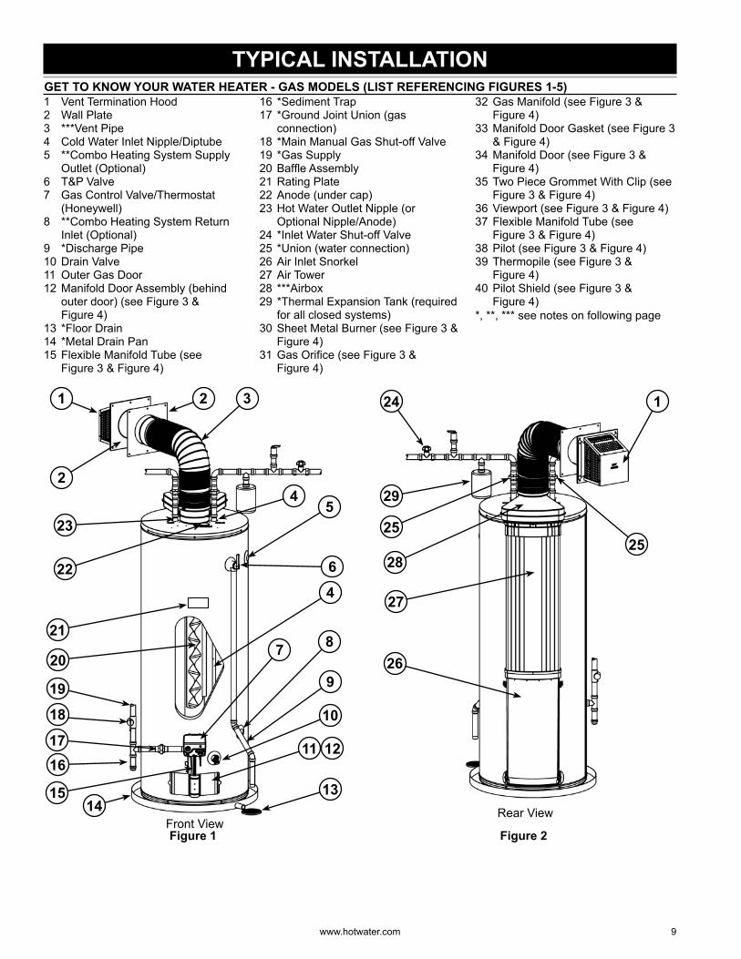
TYPICAL INSTALLATION GET TO KNOW YOUR WATER HEATER - GAS MODELS (LIST REFERENCING FIGURES 1-5)1 Vent Termination Hood2 Wall Plate3 ***Vent Pipe4 Cold Water Inlet Nipple/Diptube5 **Combo Heating System Supply
Outlet (Optional)6 T&P Valve7 Gas Control Valve/Thermostat
(Honeywell)8 **Combo Heating System Return
Inlet (Optional)9 *Discharge Pipe10 Drain Valve11 Outer Gas Door12 Manifold Door Assembly (behind
outer door) (see Figure 3 & Figure 4)
13 *Floor Drain14 *Metal Drain Pan15 Flexible Manifold Tube (see
Figure 3 & Figure 4)
16 *Sediment Trap17 *Ground Joint Union (gas
connection)18 *Main Manual Gas Shut-off Valve19 *Gas Supply20 Baffl e Assembly21 Rating Plate22 Anode (under cap)23 Hot Water Outlet Nipple (or
Optional Nipple/Anode)24 *Inlet Water Shut-off Valve25 *Union (water connection)26 Air Inlet Snorkel27 Air Tower28 ***Airbox29 *Thermal Expansion Tank (required
for all closed systems)30 Sheet Metal Burner (see Figure 3 &
Figure 4)31 Gas Orifi ce (see Figure 3 &
Figure 4)
32 Gas Manifold (see Figure 3 & Figure 4)
33 Manifold Door Gasket (see Figure 3 & Figure 4)
34 Manifold Door (see Figure 3 & Figure 4)
35 Two Piece Grommet With Clip (see Figure 3 & Figure 4)
36 Viewport (see Figure 3 & Figure 4)37 Flexible Manifold Tube (see
Figure 3 & Figure 4)38 Pilot (see Figure 3 & Figure 4)39 Thermopile (see Figure 3 &
Figure 4)40 Pilot Shield (see Figure 3 &
Figure 4)*, **, *** see notes on following page
Front View
23
1 32
6
20
4
9
10
1314
15
1617
18
19
2
21
11 12
4
7
22
8
5
Figure 1
Rear View
24
29
2525
26
1
27
28
Figure 2
10 www. hotwater .com
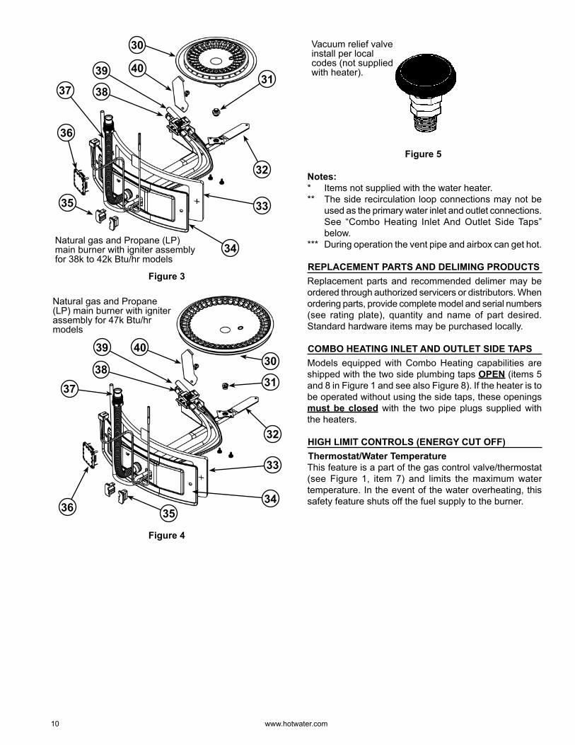
Natural gas and Propane (LP) main burner with igniter assembly for 38k to 42k Btu/hr models
31
36
38
39
30
33
34
35
32
37
40
Figure 3
37
Natural gas and Propane (LP) main burner with igniter assembly for 47k Btu/hr models
353634
33
32
31
4039
3830
Figure 4
Vacuum relief valve install per local codes (not supplied with heater).
Figure 5
Notes:* Items not supplied with the water heater.** The side recirculation loop connections may not be
used as the primary water inlet and outlet connections. See “Combo Heating Inlet And Outlet Side Taps” below.
*** During operation the vent pipe and airbox can get hot.
REPLACEMENT PARTS AND DELIMING PRODUCTSReplacement parts and recommended delimer may be ordered through authorized servicers or distributors. When ordering parts, provide complete model and serial numbers (see rating plate), quantity and name of part desired. Standard hardware items may be purchased locally.
COMBO HEATING INLET AND OUTLET SIDE TAPSModels equipped with Combo Heating capabilities are shipped with the two side plumbing taps OPEN (items 5 and 8 in Figure 1 and see also Figure 8). If the heater is to be operated without using the side taps, these openings must be closed with the two pipe plugs supplied with the heaters.
HIGH LIMIT CONTROLS (ENERGY CUT OFF) Thermostat/Water TemperatureThis feature is a part of the gas control valve/thermostat (see Figure 1, item 7) and limits the maximum water temperature. In the event of the water overheating, this safety feature shuts off the fuel supply to the burner.
www. hotwater .com 11
LOCATING THE NEW WATER HEATER FACTS TO CONSIDER ABOUT THE LOCATIONCarefully choose an indoor location for the new water heater because the placement is a very important consideration for the safety of the occupants in the building and for the most economical use of the appliance. This water heater is not for use in manufactured (mobile) homes or outdoor installation.Whether replacing an old water heater or putting the water heater in a new location, the following critical points must be observed:1. Select a location indoors as close as practical to the
vent termination position. Figure 28 shows the venting distances that the heater can be from the outside wall. Ensure the vent termination position maintains the clearances as outlined in Figure 28 thru Figure 30.
2. Selected location must provide adequate clearances for servicing and proper operation of the water heater.
3. Avoid locations that could cause the water heater to freeze from outside air.
4. Avoid locations that expose the water heater to direct sunlight.
5. Keep combustibles such as boxes, magazines, clothes, etc., away from the water heater area.
• All water heaters eventually leak.
• Do not install without adequate drainage.
Property Damage Hazard
CAUTION
Installation of the water heater must be accomplished in such a manner that if the tank or any connections should leak, the fl ow of water will not cause damage to the structure. For this reason it is not advisable to install the water heater in an attic or upper fl oor. In all cases, a metal drain pan should be installed under the water heater. Metal drain pans are available at your local hardware store. Such a metal drain pan must have a clearance of at least 1” greater than any point on the water heater’s outer jacket and must be piped to an adequate drain. The pan must have a maximum depth of 1.75” .Water heater life depends upon water quality, water pressure and the environment in which the water heater is installed. Water heaters are sometimes installed in locations where leakage may result in property damage, even with the use of a metal drain pan piped to a drain. However, unanticipated damage can be reduced or prevented by a leak detector or water shut-off device used in conjunction with a piped metal drain pan. These devices are available from some plumbing supply wholesalers and retailers, and detect and react to leakage in various ways:• Sensors mounted in the metal drain pan that trigger an
alarm or turn off the incoming water to the water heater when leakage is detected.
• Sensors mounted in the metal drain pan that turn off the water supply to the entire building when water is detected in the metal drain pan.
• Water supply shut-off devices that activate based on the water pressure differential between the cold water and hot water pipes connected to the water heater.
• Devices that will turn off the gas supply to a gas water heater while at the same time shutting off its water supply.
EXTERNAL/INTERNAL DAMAGEDo not operate the water heater until it has been fully checked out by a qualifi ed technician, if the water heater:• Has been exposed to fi re or damage.• Displays evidence of sooting.• Produces steam or unusually hot water.If the water heater has been fl ooded it must be replaced.
12 www. hotwater .com
AIR REQUIREMENTSFor safe operation an adequate supply of fresh, uncontaminated air must be provided for combustion.This gas-fi red water heater is a direct vent model. It connects directly to the outside of the building through the vent termination hood. The hood operates as both the combustion air intake and the heater exhaust port (see Figure 16).All combustion air is obtained from outside the building through this hood. Ensure the area around the termination hood is always kept clear and that the air supply is not exposed to contamination or fl ammable vapo rs.
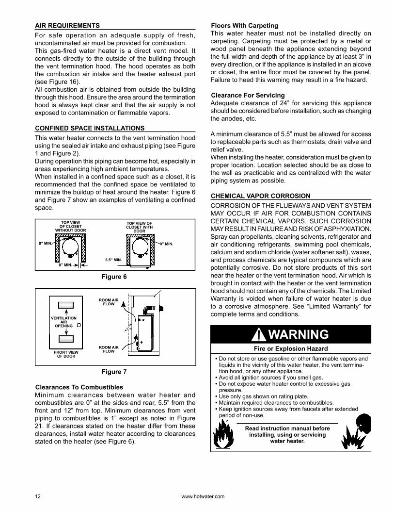
CONFINED SPACE INSTALLATIONSThis water heater connects to the vent termination hood using the sealed air intake and exhaust piping (see Figure 1 and Figure 2).During operation this piping can become hot, especially in areas experiencing high ambient temperatures.When installed in a confi ned space such as a closet, it is recommended that the confi ned space be ventilated to minimize the buildup of heat around the heater. Figure 6 and Figure 7 show an examples of ventilating a confi ned space.
0” MIN.
0” MIN. 0” MIN.
5.5” MIN.
TOP VIEW OF CLOSET
WITHOUT DOOR
TOP VIEW OF CLOSET WITH
DOOR
Figure 6
FRONT VIEW OF DOOR
ROOM AIR FLOW
ROOM AIR FLOW
VENTILATIONAIR
OPENING
Figure 7
Clearances To CombustiblesMinimum clearances between water heater and combustibles are 0” at the sides and rear, 5.5” from the front and 12” from top. Minimum clearances from vent piping to combustibles is 1” except as noted in Figure 21. If clearances stated on the heater differ from these clearances, install water heater according to clearances stated on the heater (see Figure 6).
Floors With CarpetingThis water heater must not be installed directly on carpeting. Carpeting must be protected by a metal or wood panel beneath the appliance extending beyond the full width and depth of the appliance by at least 3” in every direction, or if the appliance is installed in an alcove or closet, the entire fl oor must be covered by the panel. Failure to heed this warning may result in a fi re hazard.
Clearance For ServicingAdequate clearance of 24” for servicing this appliance should be considered before installation, such as changing the anodes, etc.
A minimum clearance of 5.5” must be allowed for access to replaceable parts such as thermostats, drain valve and relief valve.When installing the heater, consideration must be given to proper location. Location selected should be as close to the wall as practicable and as centralized with the water piping system as possible.
CHEMICAL VAPO R CORROSIONCORROSION OF THE FLUEWAYS AND VENT SYSTEM MAY OCCUR IF AIR FOR COMBUSTION CONTAINS CERTAIN CHEMICAL VAPO RS. SUCH CORROSION MAY RESULT IN FAILURE AND RISK OF ASPHYXIATION.Spray can propellants, cleaning solvents, refrigerator and air conditioning refrigerants, swimming pool chemicals, calcium and sodium chloride (water softener salt), waxes, and process chemicals are typical compounds which are potentially corrosive. Do not store products of this sort near the heater or the vent termination hood. Air which is brought in contact with the heater or the vent termination hood should not contain any of the chemicals. The Limited Warranty is voided when failure of water heater is due to a corrosive atmosphere. See “Limited Warranty” for complete terms and conditions.
Read instruction manual before installing, using or servicing
water heater.
• Do not store or use gasoline or other flammable vapors and liquids in the vicinity of this water heater, the vent termina-tion hood, or any other appliance.
• Avoid all ignition sources if you smell gas.• Do not expose water heater control to excessive gas
pressure.• Use only gas shown on rating plate.• Maintain required clearances to combustibles.• Keep ignition sources away from faucets after extended
period of non-use.
Fire or Explosion Hazard
WARNING
www. hotwater .com 13
FLAMMABLE
Do not store or use gasoline or other flammable vapors and liquids in the vicinity of this or any other appliance. Storage or use of gasoline or other flammable vapors or liquids in the vicinity of this or any other appliance can result in serious injury or death.
Can result in serious injury or deathFIRE AND EXPLOSION HAZARD
Flammable VaporsFLAMMABLES
WARNING
For continued protection against risk of fire:• Do not install water heater on
carpeted floor.• Do not operate water heater if
flood damaged.
Fire Hazard
WARNING
Breathing carbon monoxide can cause brain damage or death.Always read and understand instruction manual.
• Install water heater in accordance with the instruction manual and NFPA54.
• To avoid injury, combustion air must be taken from outdoors.
• Do not place chemical vapor emitting products near water heater or near the vent termination hood.
• Do not obstruct the vent termination hood.
Breathing Hazard - Carbon Monoxide Gas
WARNING
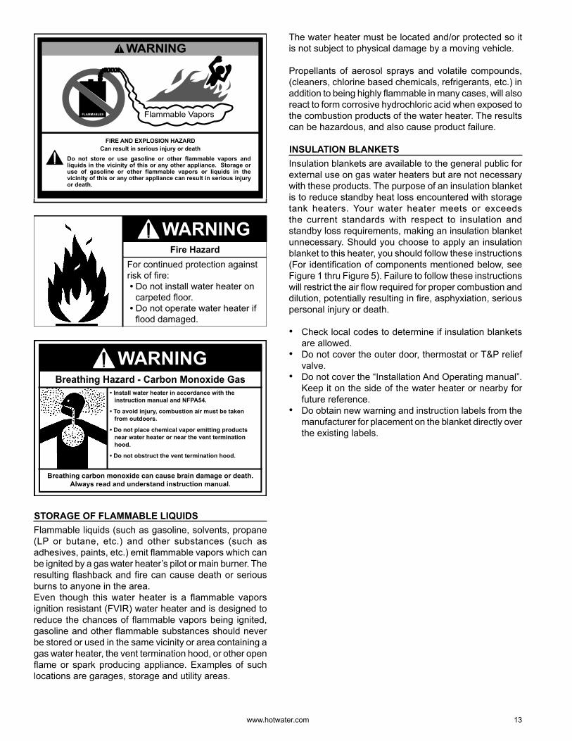
STORAGE OF FLAMMABLE LIQUIDSFlammable liquids (such as gasoline, solvents, propane (LP or butane, etc.) and other substances (such as adhesives, paints, etc.) emit fl ammable vapo rs which can be ignited by a gas water heater’s pilot or main burner. The resulting fl ashback and fi re can cause death or serious burns to anyone in the area.Even though this water heater is a fl ammable vapo rs ignition resistant (FVIR) water heater and is designed to reduce the chances of fl ammable vapo rs being ignited, gasoline and other fl ammable substances should never be stored or used in the same vicinity or area containing a gas water heater, the vent termination hood, or other open fl ame or spark producing appliance. Examples of such locations are garages, storage and utility areas.
The water heater must be located and/or protected so it is not subject to physical damage by a moving vehicle.
Propellants of aerosol sprays and volatile compounds, (cleaners, chlorine based chemicals, refrigerants, etc.) in addition to being highly fl ammable in many cases, will also react to form corrosive hydrochloric acid when exposed to the combustion products of the water heater. The results can be hazardous, and also cause product failure.
INSULATION BLANKETSInsulation blankets are available to the general public for external use on gas water heaters but are not necessary with these products. The purpose of an insulation blanket is to reduce standby heat loss encountered with storage tank heaters. Your water heater meets or exceeds the current standards with respect to insulation and standby loss requirements, making an insulation blanket unnecessary. Should you choose to apply an insulation blanket to this heater, you should follow these instructions (For identifi cation of components mentioned below, see Figure 1 thru Figure 5). Failure to follow these instructions will restrict the air fl ow required for proper combustion and dilution, potentially resulting in fi re, asphyxiation, serious personal injury or death.
• Check local codes to determine if insulation blankets are allowed.
• Do not cover the outer door, thermostat or T&P relief valve.
• Do not cover the “Installation And Operating manual”. Keep it on the side of the water heater or nearby for future reference.
• Do obtain new warning and instruction labels from the manufacturer for placement on the blanket directly over the existing labels.
14 www. hotwater .com
WATER PIPING Water PressureThe water supply pressure should not exceed 80 psi. If this occurs, a pressure reducing valve with a bypass should be installed in the cold water inlet line. This should be placed on the supply to the entire house in order to maintain equal hot and cold water pressures. See also “Closed Water Systems” and “Thermal Expansion” sections.
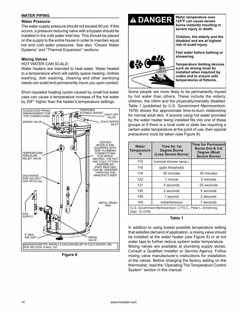
Mixing ValvesHOT WATER CAN SCALD:Water heaters are intended to heat water. Water heated to a temperature which will satisfy space heating, clothes washing, dish washing, cleaning and other sanitizing needs can scald and permanently injure you upon contact.
Short repeated heating cycles caused by small hot water uses can cause a temperature increase of the hot water by 20F° higher than the heater’s temperature settings.
MIXING VALVE
SHUT-OFF VALVE
SUGGESTED PIPING ARRANGEMENT FOR TOP CONNECTIONS
COLD WATER INLET
TEMPERED POTABLE WATER
DISCHARGE PIPE (DO NOT CAP OR PLUG)
GAS SUPPLY
TEMPERATURE-PRESSURE RELIEF VALVE
DRAIN VALVE
METAL DRAIN PAN
6 ” MAX. AIR GAP*
CERTAIN MODELS ARE
EQUIPPED WITH SIDE PLUMBING CONNECTIONS
FOR SPACE HEATING. THE HOT AND COLD FITTING
ASSEMBLIES (PART #9001262)
CAN BE ORDERED THROUGH THE
MANUFACTURER
MASSACHUSETTS: INSTALL A VACUUM RELIEF IN COLD-WATER LINE PER SECTION 19 MGL 142.
Figure 8
Water temperature over 125°F can cause severe burns instantly resulting in severe injury or death.
Children, the elderly and the disabled and are at highest risk of scald injury.
Feel water before bathing or showering.
Temperature limiting devices such as mixing must be installed when required by codes and to ensure safe temperatures at fixtures.
BURN
HOTHOT
DANGER
Some people are more likely to be permanently injured by hot water than others. These include the elderly, children, the infi rm and the physically/mentally disabled. Table 1 (published by U.S. Government Memorandum, 1978) shows the approximate time-to-burn relationship for normal adult skin. If anyone using hot water provided by the water heater being installed fi ts into one of these groups or if there is a local code or state law requiring a certain water temperature at the point of use, then special precautions must be taken (see Figure 8).
Water Temperature
°F
Time for 1stDegree Burns
(Less Severe Burns)
Time for Permanent Burns 2nd & 3rd
Degree (Most Severe Burns)
110 (normal shower temp.)
116 (pain threshold) 116 35 minutes 45 minutes
122 1 minute 5 minutes 131 5 seconds 25 seconds 140 2 seconds 5 seconds 149 1 second 2 seconds 154 instantaneous 1 seconds
(U.S. Government Memorandum, C.P.S.C., Peter L. Armstrong, Sept. 15,1978)
Table 1
In addition to using lowest possible temperature setting that satisfi es demand of application, a mixing valve should be installed at the water heater (see Figure 8) or at hot water taps to further reduce system water temperature.Mixing valves are available at plumbing supply stores. Consult a Qualifi ed Installer or Service Agency. Follow mixing valve manufacturer’s instructions for installation of the valves. Before changing the factory setting on the thermostat, read the “Operating The Temperature Control System” section in this manual.
www. hotwater .com 15
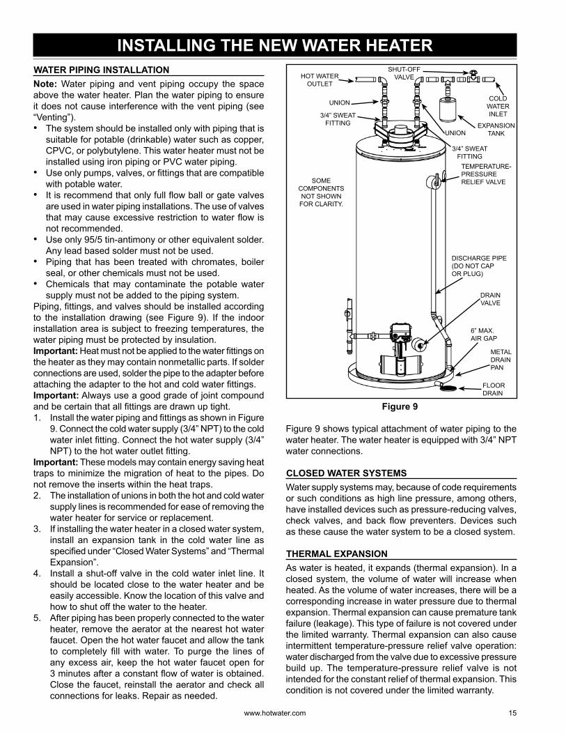
INSTALLING THE NEW WATER HEATER WATER PIPING INSTALLATIONNote: Water piping and vent piping occupy the space above the water heater. Plan the water piping to ensure it does not cause interference with the vent piping (see “Venting”).• The system should be installed only with piping that is
suitable for potable (drinkable) water such as copper, CPVC, or polybutylene. This water heater must not be installed using iron piping or PVC water piping.
• Use only pumps, valves, or fi ttings that are compatible with potable water.
• It is recommend that only full fl ow ball or gate valves are used in water piping installations. The use of valves that may cause excessive restriction to water fl ow is not recommended.
• Use only 95/5 tin-antimony or other equivalent solder. Any lead based solder must not be used.
• Piping that has been treated with chromates, boiler seal, or other chemicals must not be used.
• Chemicals that may contaminate the potable water supply must not be added to the piping system.
Piping, fi ttings, and valves should be installed according to the installation drawing (see Figure 9). If the indoor installation area is subject to freezing temperatures, the water piping must be protected by insulation.Important: Heat must not be applied to the water fi ttings on the heater as they may contain nonmetallic parts. If solder connections are used, solder the pipe to the adapter before attaching the adapter to the hot and cold water fi ttings.Important: Always use a good grade of joint compound and be certain that all fi ttings are drawn up tight.1. Install the water piping and fi ttings as shown in Figure
9. Connect the cold water supply (3/4” NPT) to the cold water inlet fi tting. Connect the hot water supply (3/4” NPT) to the hot water outlet fi tting.
Important: These models may contain energy saving heat traps to minimize the migration of heat to the pipes. Do not remove the inserts within the heat traps.2. The installation of unions in both the hot and cold water
supply lines is recommended for ease of removing the water heater for service or replacement.
3. If installing the water heater in a closed water system, install an expansion tank in the cold water line as specifi ed under “Closed Water Systems” and “Thermal Expansion”.
4. Install a shut-off valve in the cold water inlet line. It should be located close to the water heater and be easily accessible. Know the location of this valve and how to shut off the water to the heater.
5. After piping has been properly connected to the water heater, remove the aerator at the nearest hot water faucet. Open the hot water faucet and allow the tank to completely fi ll with water. To purge the lines of any excess air, keep the hot water faucet open for 3 minutes after a constant fl ow of water is obtained. Close the faucet, reinstall the aerator and check all connections for leaks. Repair as needed.
METAL DRAIN PAN
FLOORDRAIN
HOT WATER OUTLET
COLD WATER INLET
UNION
UNION
3/4” SWEAT FITTING
3/4” SWEAT FITTING
TEMPERATURE-PRESSURE RELIEF VALVE
DISCHARGE PIPE(DO NOT CAP OR PLUG)
6 ” MAX.AIR GAP
DRAINVALVE
SHUT-OFF VALVE
SOME COMPONENTS NOT SHOWN
FOR CLARITY.
EXPANSION TANK
Figure 9
Figure 9 shows typical attachment of water piping to the water heater. The water heater is equipped with 3/4” NPT water connections.
CLOSED WATER SYSTEMSWater supply systems may, because of code requirements or such conditions as high line pressure, among others, have installed devices such as pressure-reducing valves, check valves, and back fl ow preventers. Devices such as these cause the water system to be a closed system.
THERMAL EXPANSIONAs water is heated, it expands (thermal expansion). In a closed system, the volume of water will increase when heated. As the volume of water increases, there will be a corresponding increase in water pressure due to thermal expansion. Thermal expansion can cause premature tank failure (leakage). This type of failure is not covered under the limited warranty. Thermal expansion can also cause intermittent temperature-pressure relief valve operation: water discharged from the valve due to excessive pressure build up. The temperature-pressure relief valve is not intended for the constant relief of thermal expansion. This condition is not covered under the limited warranty.
16 www. hotwater .com
A properly-sized and charged thermal expansion tank must be installed on all closed systems to control the harmful effects of thermal expansion. Contact a plumbing service agency or your retail supplier regarding the installation of a thermal expansion tank.
Note: To protect against untimely corrosion of hot and cold water fi ttings, it is recommended that di-electric unions or couplings be installed on this water heater when connected to copper pipe.
• Avoid water heater damage.• Install thermal expansion tank if necessary.• Do not apply heat to cold-water inlet or hot-water outlet.• Contact qualified installer or service agency.
Property Damage Hazard
CAUTION
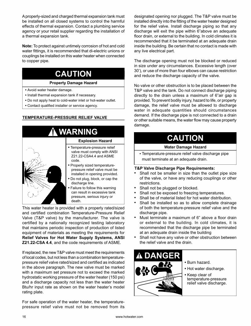
TEMPERATURE-PRESSURE RELIEF VALVE
• Temperature-pressure relief valve must comply with ANSI Z21.22-CSA4.4 and ASME code.
• Properly sized temperature-pressure relief valve must be installed in opening provided.
• Do not plug, block, or cap the discharge line.
• Failure to follow this warning can result in excessive tank pressure, serious injury or death.
Explosion Hazard
WARNING
This water heater is provided with a properly rated/sized and certifi ed combination Temperature-Pressure Relief Valve (T&P valve) by the manufacturer. The valve is certifi ed by a nationally recognized testing laboratory that maintains periodic inspection of production of listed equipment of materials as meeting the requirements for Relief Valves for Hot Water Supply Systems, ANSI Z21.22-CSA 4.4, and the code requirements of ASME.
If replaced, the new T&P valve must meet the requirements of local codes, but not less than a combination temperature-pressure relief valve rated/sized and certifi ed as indicated in the above paragraph. The new valve must be marked with a maximum set pressure not to exceed the marked hydrostatic working pressure of the water heater (150 psi) and a discharge capacity not less than the water heater Btu/hr input rate as shown on the water heater’s model rating plate.
For safe operation of the water heater, the temperature-pressure relief valve must not be removed from its
designated opening nor plugged. The T&P valve must be installed directly into the fi tting of the water heater designed for the relief valve. Install discharge piping so that any discharge will exit the pipe within 6 ” above an adequate fl oor drain, or external to the building. In cold climates it is recommended that it be terminated at an adequate drain inside the building. Be certain that no contact is made with any live electrical part.
The discharge opening must not be blocked or reduced in size under any circumstances. Excessive length (over 30’ ), or use of more than four elbows can cause restriction and reduce the discharge capacity of the valve.
No valve or other obstruction is to be placed between the T&P valve and the tank. Do not connect discharge piping directly to the drain unless a maximum of 6 ” air gap is provided. To prevent bodily injury, hazard to life, or property damage, the relief valve must be allowed to discharge water in adequate quantities should circumstances demand. If the discharge pipe is not connected to a drain or other suitable means, the water fl ow may cause property damage.
• Temperature-pressure relief valve discharge pipe must terminate at an adequate drain.
Water Damage Hazard
CAUTION
T&P Valve Discharge Pipe Requirements:• Shall not be smaller in size than the outlet pipe size
of the valve, or have any reducing couplings or other restrictions.
• Shall not be plugged or blocked.• Shall not be exposed to freezing temperatures.• Shall be of material listed for hot water distribution.• Shall be installed so as to allow complete drainage
of both the temperature-pressure relief valve and the discharge pipe.
• Must terminate a maximum of 6 ” above a fl oor drain or external to the building. In cold climates, it is recommended that the discharge pipe be terminated at an adequate drain inside the building
• Shall not have any valve or other obstruction between the relief valve and the drain.
• Burn hazard.• Hot water discharge.• Keep clear of
temperature-pressure relief valve discharge.
BURN
HOTHOT
DANGER
www. hotwater .com 17
The T&P valve must be manually operated at least once a year. Caution should be taken to ensure1. no one is in front of or around the outlet of the
discharge line, and2. the water manually discharged will not cause any
bodily injury or property damage because the water may be extremely hot.
If after manually operating the valve, it fails to completely reset and continues to release water, immediately close the cold water inlet to the water heater, follow the draining instructions in this manual, and replace the temperature-pressure relief valve with a properly rated/sized new one.Note: The purpose of a temperature-pressure relief valve is to prevent excessive temperatures and pressures in the storage tank. The T&P valve is not intended for the constant relief of thermal expansion. A properly sized thermal expansion tank must be installed on all closed systems to control thermal expansion, see “Closed Water Systems” and “Thermal Expansion” sections.
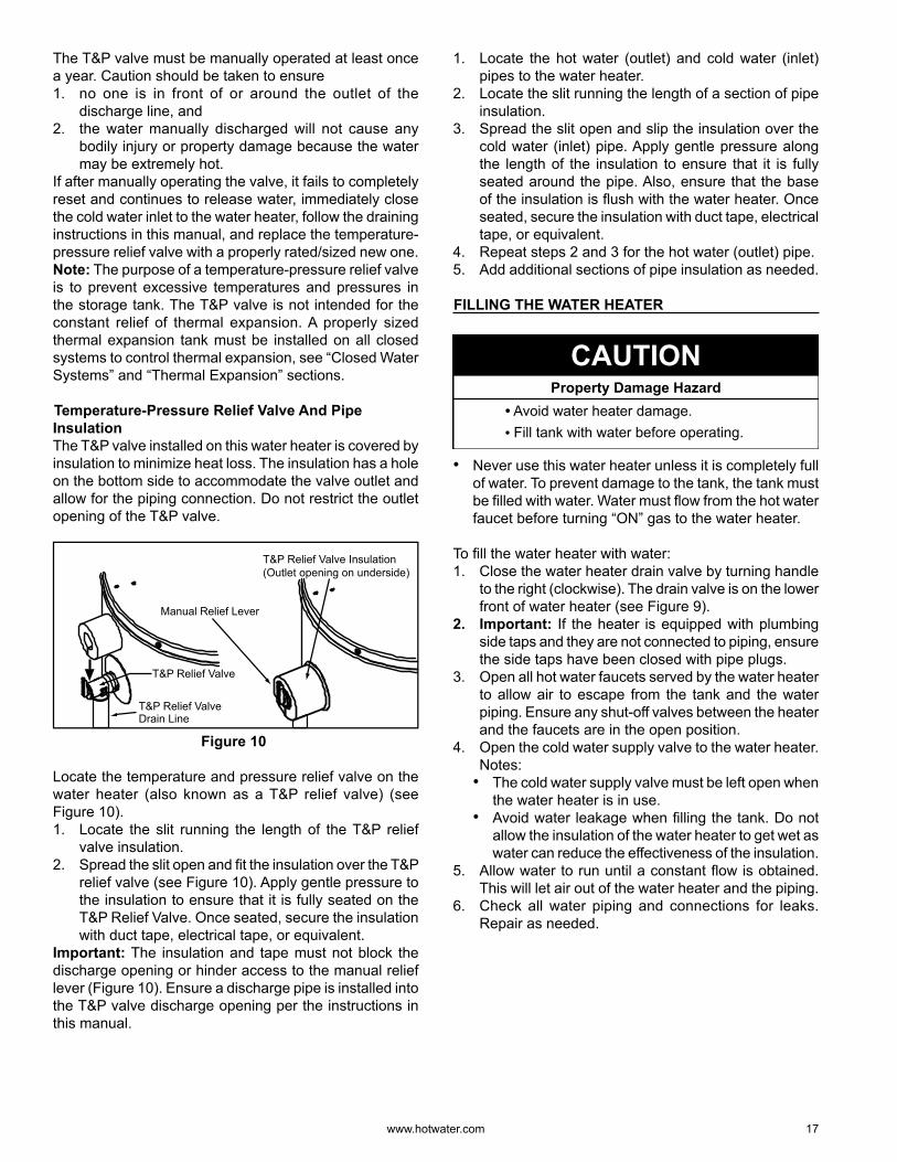
Temperature-Pressure Relief Valve And Pipe InsulationThe T&P valve installed on this water heater is covered by insulation to minimize heat loss. The insulation has a hole on the bottom side to accommodate the valve outlet and allow for the piping connection. Do not restrict the outlet opening of the T&P valve.
T&P Relief Valve
T&P Relief ValveDrain Line
Manual Relief Lever
T&P Relief Valve Insulation(Outlet opening on underside)
Figure 10
Locate the temperature and pressure relief valve on the water heater (also known as a T&P relief valve) (see Figure 10).1. Locate the slit running the length of the T&P relief
valve insulation.2. Spread the slit open and fi t the insulation over the T&P
relief valve (see Figure 10). Apply gentle pressure to the insulation to ensure that it is fully seated on the T&P Relief Valve. Once seated, secure the insulation with duct tape, electrical tape, or equivalent.
Important: The insulation and tape must not block the discharge opening or hinder access to the manual relief lever (Figure 10). Ensure a discharge pipe is installed into the T&P valve discharge opening per the instructions in this manual.
1. Locate the hot water (outlet) and cold water (inlet) pipes to the water heater.
2. Locate the slit running the length of a section of pipe insulation.
3. Spread the slit open and slip the insulation over the cold water (inlet) pipe. Apply gentle pressure along the length of the insulation to ensure that it is fully seated around the pipe. Also, ensure that the base of the insulation is fl ush with the water heater. Once seated, secure the insulation with duct tape, electrical tape, or equivalent.
4. Repeat steps 2 and 3 for the hot water (outlet) pipe.5. Add additional sections of pipe insulation as needed.
FILLING THE WATER HEATER
• Avoid water heater damage.• Fill tank with water before operating.
Property Damage Hazard
CAUTION
• Never use this water heater unless it is completely full of water. To prevent damage to the tank, the tank must be fi lled with water. Water must fl ow from the hot water faucet before turning “ON” gas to the water heater.
To fi ll the water heater with water:1. Close the water heater drain valve by turning handle
to the right (clockwise). The drain valve is on the lower front of water heater (see Figure 9).
2. Important: If the heater is equipped with plumbing side taps and they are not connected to piping, ensure the side taps have been closed with pipe plugs.
3. Open all hot water faucets served by the water heater to allow air to escape from the tank and the water piping. Ensure any shut-off valves between the heater and the faucets are in the open position.
4. Open the cold water supply valve to the water heater.Notes:
• The cold water supply valve must be left open when the water heater is in use.
• Avoid water leakage when fi lling the tank. Do not allow the insulation of the water heater to get wet as water can reduce the effectiveness of the insulation.
5. Allow water to run until a constant fl ow is obtained. This will let air out of the water heater and the piping.
6. Check all water piping and connections for leaks. Repair as needed.
18 www. hotwater .com
SPACE HEATING AND POTABLE WATER SYSTEMSThis appliance has been design certifi ed as complying with American National Standard/CSA Standard for water heaters and are considered suitable for Water (Potable) Heating and Space Heating. Note: This water heater may be used in combination potable water/space heating system. Do not use in a space heating only application.
Toxic Chemical Hazard
WARNING• Do not connect to non-potable water system.
Note: Ensure the water heater has been properly sized to accommodate the needs of the hot water demand and space heating load. Undersizing the water heater can result in insuffi cient hot water, excessive condensation and ineffi cient operation.
• This water heater should not be connected to any heating systems or components previously used with a non-potable water heating appliance.
• All piping components connected to this unit for space heating applications should be suitable for use with potable water.
• Pumps, valves, piping and fi ttings must be compatible with potable water.
• Toxic chemicals, such as those used for boiler treatment shall not be introduced into the potable water used for space heating.
• When the system requires water for space heating at temperatures higher than required for domestic water purposes, a mixing valve must be installed. Please refer to Figure 8 for suggested piping arrangement.
• Be sure to follow the manual(s) shipped with the air handler or other type heating system.
• This water heater is not to be used as a replacement for an existing boiler installation.
• Do not use with piping that has been treated with chromates, boiler seal or other chemicals and do not add any chemicals to the water heater piping.
• A properly installed fl ow control valve is required to prevent thermosiphoning. Thermosiphoning is the result of a continuous fl ow of water through the air handler circuit during the off cycle. Weeping (blow off) of the temperature-pressure relief valve (T&P) or higher than normal water temperatures are the fi rst signs of thermosiphoning.
• The hot water line from the water heater should be vertical past any mixing valve or supply line to the heating system to remove air bubbles from the system.
www. hotwater .com 19
COMBO HEATINGThis section serves as a guide for the installation and use of “Combo” heating systems utilizing a domestic water heater that has been specifi cally approved for such use. It is written for those knowledgeable in the required trades and professionals involved in the design and installation of Combo Heating Systems.It is the responsibility of the installer/designer to follow all applicable codes to ensure the effectiveness and safety of the installation.
System RequirementsThe following requirements must be met for the installation of Combo Heating Systems:1. All components used for the distribution of water in
the heating loop must be suitable for potable water. These include all piping, fi ttings, solder and fl uxes, pumps for circulation of water, valves, etc.
2. The water heater must not be connected to a hydronic heating system that has been used previously.
3. No boiler treatment chemicals of any kind shall be introduced into the system.
4. The Combo System components must be selected and sized to meet and maintain the total calculated demands for both domestic service hot water and space heating requirement. The sizing and installation must be performed in accordance with good engineering practice such as “ASHRAE Handbooks”, HRAI’s Unifi ed Combo Guidelines, “Hydronics Institute Manuals”, ANSI Z223.1, CSA F280, National/Provincial Building Codes, ANSI and/or codes having jurisdiction.
5. The air handler (fan coil) and/or the circulating pump in a baseboard hydronic loop will require a dedicated 120V circuit. This must be provided and identifi ed for this purpose.
6. All piping between the water heater and the air handler or hydronic baseboard loop must be adequately insulated to reduce heat loss.
7. If the local jurisdiction requires a back-fl ow preventer in the cold water line, an expansion tank of adequate size must be installed.
8. “Combo” Heating Systems require higher water temperatures than other applications. When the system is used to supply water for Combo Heating applications, a means, such as mixing valve, must be installed to temper the water in order to reduce scald hazard potential (see Figure 11 & Figure 12).
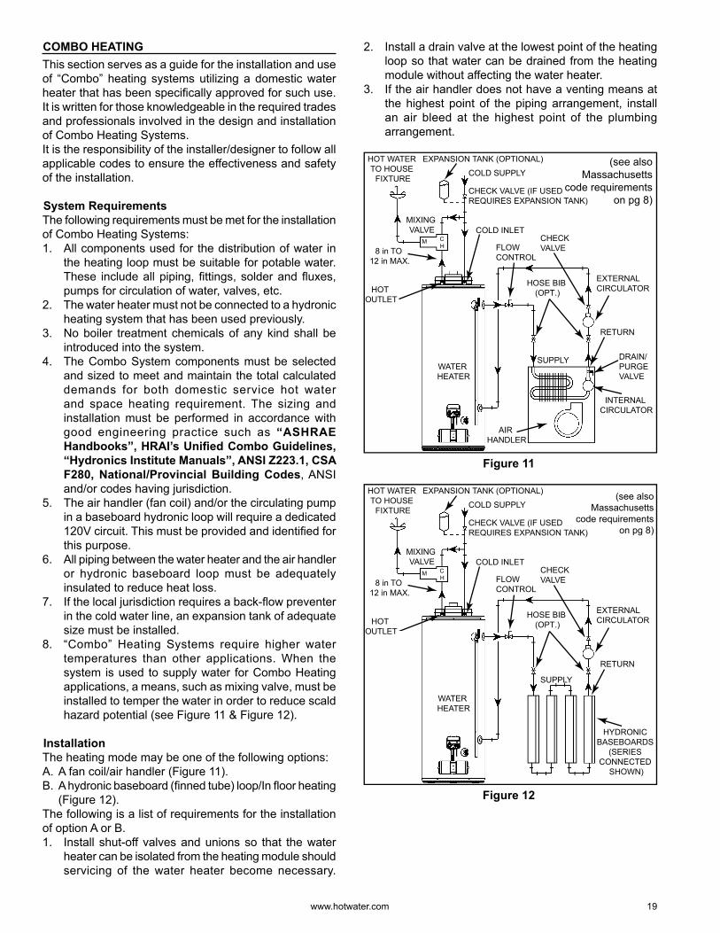
InstallationThe heating mode may be one of the following options:A. A fan coil/air handler (Figure 11).B. A hydronic baseboard (fi nned tube) loop/In fl oor heating
(Figure 12).The following is a list of requirements for the installation of option A or B.1. Install shut-off valves and unions so that the water
heater can be isolated from the heating module should servicing of the water heater become necessary.
2. Install a drain valve at the lowest point of the heating loop so that water can be drained from the heating module without affecting the water heater.
3. If the air handler does not have a venting means at the highest point of the piping arrangement, install an air bleed at the highest point of the plumbing arrangement.
WATER HEATER
8 in TO 12 in MAX.
HOT OUTLET
EXPANSION TANK (OPTIONAL)
MIXING VALVE COLD INLET
CHECK VALVE (IF USED REQUIRES EXPANSION TANK)
COLD SUPPLY
HOSE BIB (OPT.)
FLOW CONTROL
SUPPLY
RETURN
CHECK VALVE
EXTERNAL CIRCULATOR
AIR HANDLER
HOT WATER TO HOUSE
FIXTURE
CH
M
INTERNAL CIRCULATOR
DRAIN/PURGE VALVE
(see also Massachusetts
code requirements on pg 8)
Figure 11
WATER HEATER
8 in TO 12 in MAX.
HOT OUTLET
EXPANSION TANK (OPTIONAL)
MIXING VALVE COLD INLET
CHECK VALVE (IF USED REQUIRES EXPANSION TANK)
COLD SUPPLY
HOSE BIB (OPT.)
FLOW CONTROL
SUPPLY
RETURN
CHECK VALVE
EXTERNAL CIRCULATOR
HOT WATER TO HOUSE
FIXTURE
CH
M
HYDRONIC BASEBOARDS
(SERIES CONNECTED
SHOWN)
(see also Massachusetts
code requirements on pg 8)
Figure 12
20 www. hotwater .com
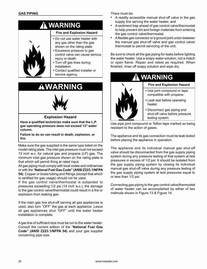
GAS PIPING
• Do not use water heater with any gas other than the gas shown on the rating plate.
• Excessive pressure to gas control valve can cause serious injury or death.
• Turn off gas lines during installation.
• Contact qualified installer or service agency.
Fire and Explosion Hazard
WARNING
Explosion HazardHave a qualified technician make sure that the L.P. gas operating pressure does not exceed 13" water column.Failure to do so can result in death, explosion, or fire.
WARNING
Make sure the gas supplied is the same type listed on the model rating plate. The inlet gas pressure must not exceed 13 inch w.c. for natural gas and propane (LP) gas. The minimum inlet gas pressure shown on the rating plate is that which will permit fi ring at rated input.All gas piping must comply with local codes and ordinances or with the “National Fuel Gas Code” (ANSI Z223.1/NFPA 54). Copper or brass tubing and fi ttings (except that which is certifi ed for gas usage) should not be used.If the gas control valve/thermostat is subjected to pressures exceeding 1/2 psi (14 inch w.c.), the damage to the gas control valve/thermostat could result in a fi re or explosion from leaking gas.
If the main gas line shut-off serving all gas appliances is used, also turn “OFF” the gas at each appliance. Leave all gas appliances shut “OFF” until the water heater installation is complete.
A gas line of suffi cient size must be run to the water heater. Consult the current edition of the “National Fuel Gas Code” (ANSI Z223.1/NFPA 54) and your gas supplier concerning pipe size.
There must be:• A readily accessible manual shut-off valve in the gas
supply line serving the water heater, and• A sediment trap ahead of gas control valve/thermostat
to help prevent dirt and foreign materials from entering the gas control valve/thermostat.
• A fl exible gas connector or a ground joint union between the manual gas shut-off valve and gas control valve/thermostat to permit servicing of the unit.
Be sure to check all the gas piping for leaks before lighting the water heater. Use a soapy water solution, not a match or open fl ame. Repair and retest as required. When fi nished, rinse off soapy solution and wipe dry.
• Use joint compound or tape compatible with propane.
• Leak test before operating heater.
• Disconnect gas piping and shut-off valve before pressure testing system.
Fire and Explosion Hazard
WARNING
Use pipe joint compound or Tefl on tape marked as being resistant to the action of gases.
The appliance and its gas connection must be leak tested before placing the appliance in operation.
The appliance and its individual manual gas shut-off valve should be disconnected from the gas supply piping system during any pressure testing of that system at test pressures in excess of 1/2 psi. It should be isolated from the gas supply piping system by closing its individual manual gas shut-off valve during any pressure testing of the gas supply piping system at test pressures equal to or less than 1/2 psi.
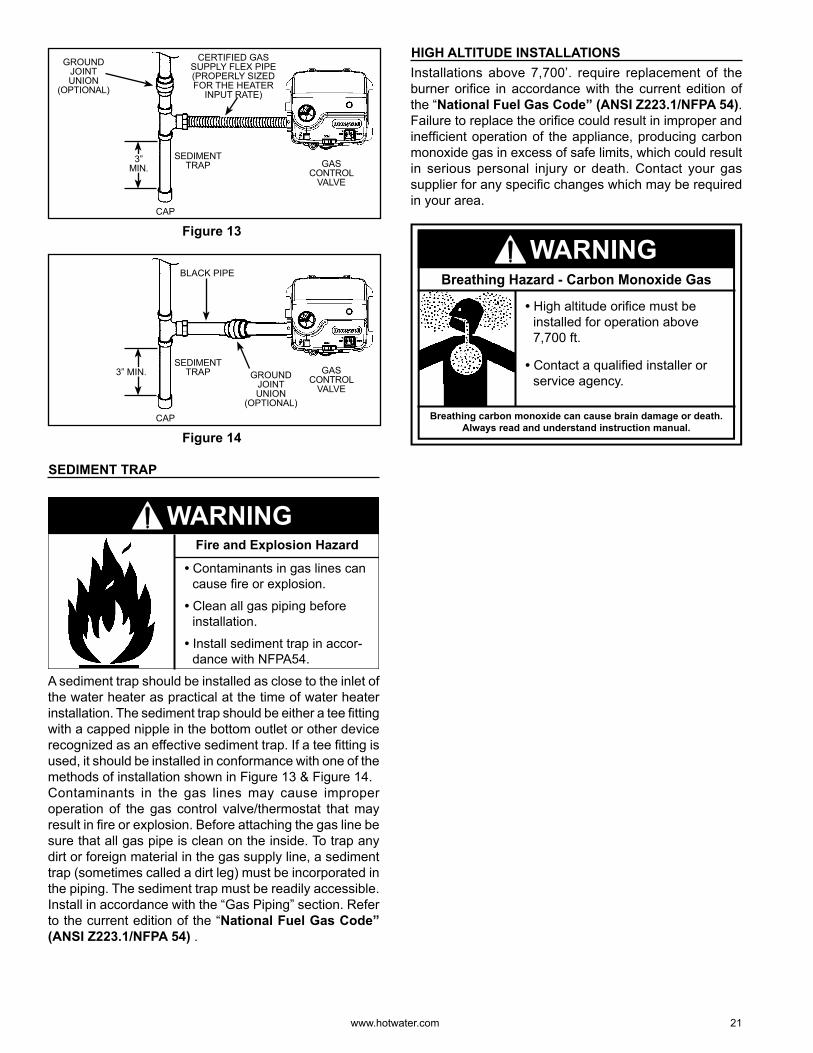
Connecting gas piping to the gas control valve/thermostat of water heater can be accomplished by either of two methods shown in Figure 13 & Figure 14.
www. hotwater .com 21
CERTIFIED GAS SUPPLY FLEX PIPE (PROPERLY SIZED FOR THE HEATER
INPUT RATE)
SEDIMENT TRAP GAS
CONTROL VALVE
GROUND JOINT UNION
(OPTIONAL)
CAP
3” MIN.
Figure 13
BLACK PIPE
SEDIMENT TRAP GAS
CONTROL VALVE
GROUND JOINT UNION
(OPTIONAL)CAP
3” MIN.
Figure 14
SEDIMENT TRAP
• Contaminants in gas lines can cause fire or explosion.
• Clean all gas piping before installation.
• Install sediment trap in accor-dance with NFPA54.
Fire and Explosion Hazard
WARNING
A sediment trap should be installed as close to the inlet of the water heater as practical at the time of water heater installation. The sediment trap should be either a tee fi tting with a capped nipple in the bottom outlet or other device recognized as an effective sediment trap. If a tee fi tting is used, it should be installed in conformance with one of the methods of installation shown in Figure 13 & Figure 14.Contaminants in the gas lines may cause improper operation of the gas control valve/thermostat that may result in fi re or explosion. Before attaching the gas line be sure that all gas pipe is clean on the inside. To trap any dirt or foreign material in the gas supply line, a sediment trap (sometimes called a dirt leg) must be incorporated in the piping. The sediment trap must be readily accessible. Install in accordance with the “Gas Piping” section. Refer to the current edition of the “National Fuel Gas Code” (ANSI Z223.1/NFPA 54) .
HIGH ALTITUDE INSTALLATIONSInstallations above 7,700’ . require replacement of the burner orifi ce in accordance with the current edition of the “National Fuel Gas Code” (ANSI Z223.1/NFPA 54). Failure to replace the orifi ce could result in improper and ineffi cient operation of the appliance, producing carbon monoxide gas in excess of safe limits, which could result in serious personal injury or death. Contact your gas supplier for any specifi c changes which may be required in your area.
Breathing carbon monoxide can cause brain damage or death.Always read and understand instruction manual.
• High altitude orifice must be installed for operation above 7,700 ft.
• Contact a qualified installer or service agency.
Breathing Hazard - Carbon Monoxide Gas
WARNING
22 www. hotwater .com
VENTINGThis direct vent water heater uses a sealed venting system to supply fresh combustion air to the heater and to exhaust the products of combustion (fl ue gases) to the outdoors. The venting is a “pipe in a pipe” system. The inner (3”) piping carries out the exhaust fl ue gases while the outer (6”) piping carries in fresh combustion air. The corrugated end of the vent piping connects to the top of the water heater and the opposite end connects to the vent termination hood which will be mounted on the exterior wall (see Figure 16). Figure 16 shows the hot exhaust gas exit and the location of the combustion air intake.Figure 19 thru Figure 26 show how to assemble and connect the venting system.Figure 28 thru Figure 30 show various installation options.
DO NOT STORE OR USE GASOLINE OR OTHER FLAMMABLE VAPO RS AND LIQUIDS IN THE VICINITY OF THE VENT TERMINATION HOOD.
NEVER OPERATE THE WATER HEATER UNLESS IT IS VENTED TO THE OUTDOORS AND HAS ADEQUATE AIR SUPPLY TO AVOID RISKS OF IMPROPER OPERATION, FIRE, EXPLOSION OR ASPHYXIATION.
DO NOT OBSTRUCT THE FLOW OF COMBUSTION AND VENTILATING AIR. ADEQUATE AIR FOR COMBUSTION AND VENTILATION MUST BE PROVIDED FOR SAFE OPERATION.
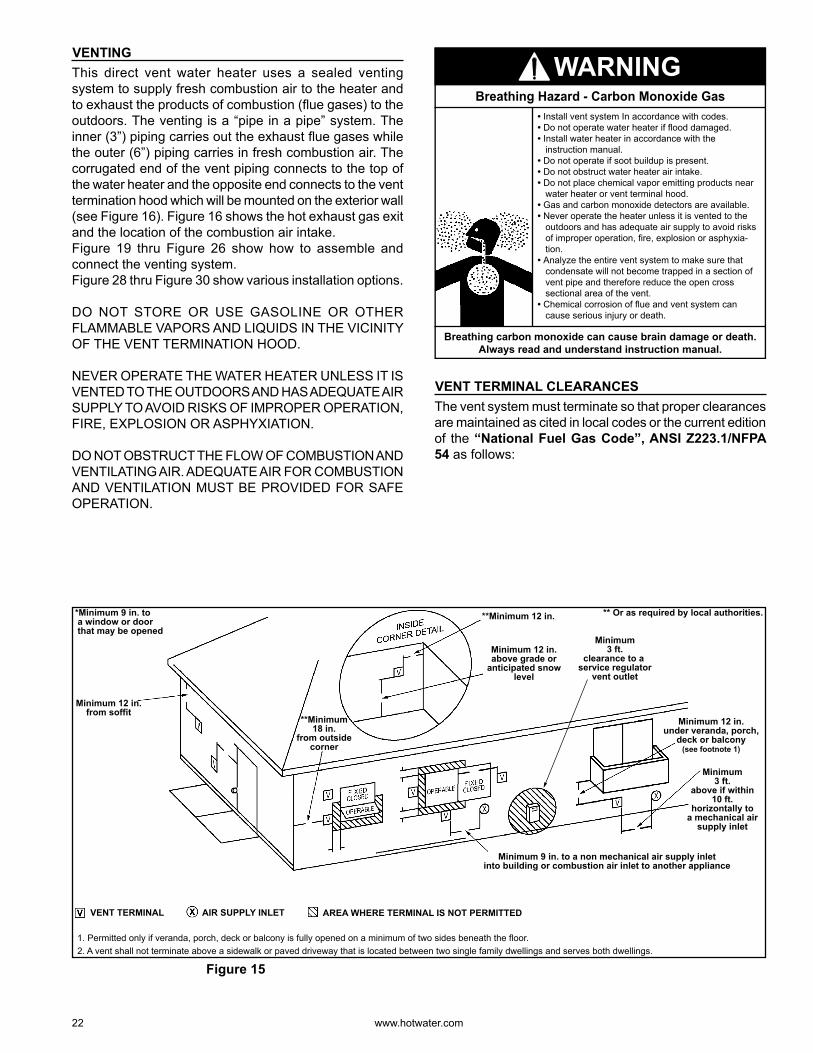
**Minimum 12 in.
Minimum 12 in.above grade or
anticipated snowlevel
Minimum 12 in.under veranda, porch,
deck or balcony(see footnote 1)
Minimum3 ft.
above if within10 ft.
horizontally toa mechanical air
supply inlet
Minimum 9 in. to a non mechanical air supply inletinto building or combustion air inlet to another appliance
Minimum 12 in.from soffit
*Minimum 9 in. to a window or door that may be opened
**Minimum18 in.
from outsidecorner
1. Permitted only if veranda, porch, deck or balcony is fully opened on a minimum of two sides beneath the floor.2. A vent shall not terminate above a sidewalk or paved driveway that is located between two single family dwellings and serves both dwellings.
AREA WHERE TERMINAL IS NOT PERMITTEDVENT TERMINAL AIR SUPPLY INLET
Minimum3 ft.
clearance to a service regulator
vent outlet
** Or as required by local authorities.
Figure 15
Breathing carbon monoxide can cause brain damage or death.Always read and understand instruction manual.
• Install vent system In accordance with codes.• Do not operate water heater if flood damaged.• Install water heater in accordance with the
instruction manual.• Do not operate if soot buildup is present.• Do not obstruct water heater air intake.• Do not place chemical vapor emitting products near
water heater or vent terminal hood.• Gas and carbon monoxide detectors are available.• Never operate the heater unless it is vented to the
outdoors and has adequate air supply to avoid risks of improper operation, fire, explosion or asphyxia-tion.
• Analyze the entire vent system to make sure that condensate will not become trapped in a section of vent pipe and therefore reduce the open cross sectional area of the vent.
• Chemical corrosion of flue and vent system can cause serious injury or death.
Breathing Hazard - Carbon Monoxide Gas
WARNING
VENT TERMINAL CLEARANCESThe vent system must terminate so that proper clearances are maintained as cited in local codes or the current edition of the “National Fuel Gas Code”, ANSI Z223.1/NFPA 54 as follows:
www. hotwater .com 23
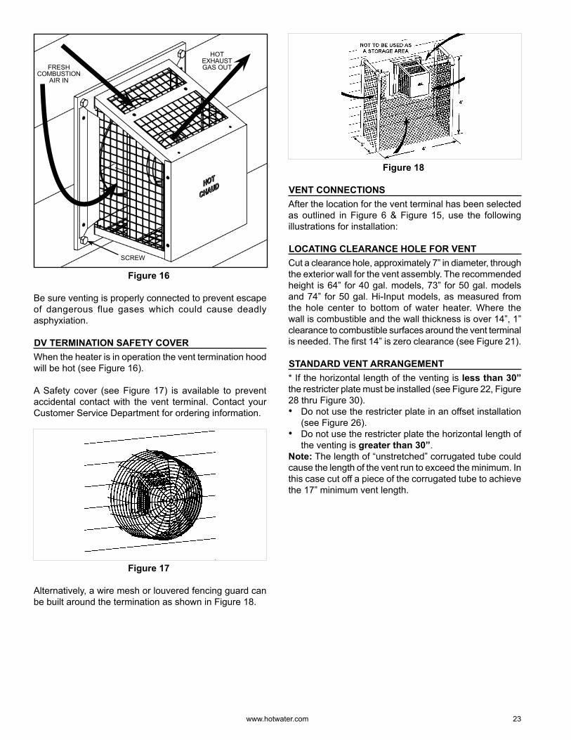
FRESH COMBUSTION
AIR IN
HOT EXHAUST GAS OUT
SCREW
Figure 16
Be sure venting is properly connected to prevent escape of dangerous flue gases which could cause deadly asphyxiation.
DV TERMINATION SAFETY COVERWhen the heater is in operation the vent termination hood will be hot (see Figure 16).
A Safety cover (see Figure 17) is available to prevent accidental contact with the vent terminal. Contact your Customer Service Department for ordering information.
Figure 17
Alternatively, a wire mesh or louvered fencing guard can be built around the termination as shown in Figure 18.
Figure 18
VENT CONNECTIONSAfter the location for the vent terminal has been selected as outlined in Figure 6 & Figure 15, use the following illustrations for installation:
LOCATING CLEARANCE HOLE FOR VENTCut a clearance hole, approximately 7” in diameter, through the exterior wall for the vent assembly. The recommended height is 64” for 40 gal. models, 73” for 50 gal. models and 74” for 50 gal. Hi-Input models, as measured from the hole center to bottom of water heater. Where the wall is combustible and the wall thickness is over 14” , 1” clearance to combustible surfaces around the vent terminal is needed. The fi rst 14” is zero clearance (see Figure 21).
STANDARD VENT ARRANGEMENT* If the horizontal length of the venting is less than 30” the restricter plate must be installed (see Figure 22, Figure 28 thru Figure 30).• Do not use the restricter plate in an offset installation
(see Figure 26).• Do not use the restricter plate the horizontal length of
the venting is greater than 30” .Note: The length of “unstretched” corrugated tube could cause the length of the vent run to exceed the minimum. In this case cut off a piece of the corrugated tube to achieve the 17” minimum vent length.
24 www. hotwater .com
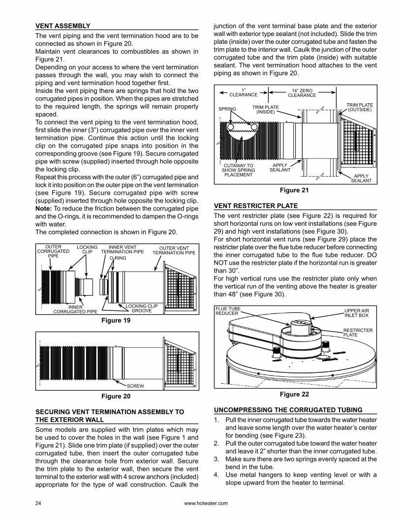
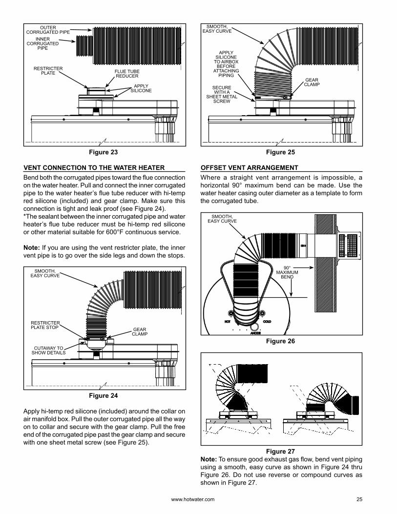
VENT ASSEMBLYThe vent piping and the vent termination hood are to be connected as shown in Figure 20.Maintain vent clearances to combustibles as shown in Figure 21.Depending on your access to where the vent termination passes through the wall, you may wish to connect the piping and vent termination hood together fi rst.Inside the vent piping there are springs that hold the two corrugated pipes in position. When the pipes are stretched to the required length, the springs will remain properly spaced.To connect the vent piping to the vent termination hood, fi rst slide the inner (3”) corrugated pipe over the inner vent termination pipe. Continue this action until the locking clip on the corrugated pipe snaps into position in the corresponding groove (see Figure 19). Secure corrugated pipe with screw (supplied) inserted through hole opposite the locking clip.Repeat this process with the outer (6”) corrugated pipe and lock it into position on the outer pipe on the vent termination (see Figure 19). Secure corrugated pipe with screw (supplied) inserted through hole opposite the locking clip.Note: To reduce the friction between the corrugated pipe and the O-rings, it is recommended to dampen the O-rings with water.The completed connection is shown in Figure 20.
INNER CORRUGATED PIPE
INNER VENT TERMINATION PIPE
OUTER VENT TERMINATION PIPE
O-RING
OUTER CORRUGATED
PIPE
LOCKING CLIP GROOVE
LOCKING CLIP
Figure 19
SCREW
Figure 20
SECURING VENT TERMINATION ASSEMBLY TO THE EXTERIOR WALLSome models are supplied with trim plates which may be used to cover the holes in the wall (see Figure 1 and Figure 21). Slide one trim plate (if supplied) over the outer corrugated tube, then insert the outer corrugated tube through the clearance hole from exterior wall. Secure the trim plate to the exterior wall, then secure the vent terminal to the exterior wall with 4 screw anchors (included) appropriate for the type of wall construction. Caulk the
junction of the vent terminal base plate and the exterior wall with exterior type sealant (not included). Slide the trim plate (inside) over the outer corrugated tube and fasten the trim plate to the interior wall. Caulk the junction of the outer corrugated tube and the trim plate (inside) with suitable sealant. The vent termination hood attaches to the vent piping as shown in Figure 20.
TRIM PLATE (INSIDE)
TRIM PLATE (OUTSIDE)
APPLY SEALANT
SPRING
CUTAWAY TO SHOW SPRING
PLACEMENT
APPLY SEALANT
14” ZERO CLEARANCE
1” CLEARANCE
Figure 21
VENT RESTRICTER PLATEThe vent restricter plate (see Figure 22) is required for short horizontal runs on low vent installations (see Figure 29) and high vent installations (see Figure 30).For short horizontal vent runs (see Figure 29) place the restricter plate over the fl ue tube reducer before connecting the inner corrugated tube to the fl ue tube reducer. DO NOT use the restricter plate if the horizontal run is greater than 30” .For high vertical runs use the restricter plate only when the vertical run of the venting above the heater is greater than 48” (see Figure 30).
UPPER AIR INLET BOX
FLUE TUBE REDUCER
RESTRICTER PLATE
Figure 22
UNCOMPRESSING THE CORRUGATED TUBING1. Pull the inner corrugated tube towards the water heater
and leave some length over the water heater’s center for bending (see Figure 23).
2. Pull the outer corrugated tube toward the water heater and leave it 2” shorter than the inner corrugated tube.
3. Make sure there are two springs evenly spaced at the bend in the tube.
4. Use metal hangers to keep venting level or with a slope upward from the heater to terminal.
www. hotwater .com 25
INNER CORRUGATED
PIPE
OUTER CORRUGATED PIPE
RESTRICTER PLATE FLUE TUBE
REDUCER
APPLY SILICONE
Figure 23
VENT CONNECTION TO THE WATER HEATERBend both the corrugated pipes toward the fl ue connection on the water heater. Pull and connect the inner corrugated pipe to the water heater’s fl ue tube reducer with hi-temp red silicone (included) and gear clamp. Make sure this connection is tight and leak proof (see Figure 24).*The sealant between the inner corrugated pipe and water heater’s fl ue tube reducer must be hi-temp red silicone or other material suitable for 600°F continuous service.
Note: If you are using the vent restricter plate, the inner vent pipe is to go over the side legs and down the stops.
SMOOTH, EASY CURVE
GEAR CLAMP
CUTAWAY TO SHOW DETAILS
RESTRICTER PLATE STOP
Figure 24
Apply hi-temp red silicone (included) around the collar on air manifold box. Pull the outer corrugated pipe all the way on to collar and secure with the gear clamp. Pull the free end of the corrugated pipe past the gear clamp and secure with one sheet metal screw (see Figure 25).
GEAR CLAMP
APPLY SILICONE
TO AIRBOX BEFORE
ATTACHING PIPING
SECURE WITH A
SHEET METAL SCREW
SMOOTH, EASY CURVE
Figure 25
OFFSET VENT ARRANGEMENTWhere a straight vent arrangement is impossible, a horizontal 90° maximum bend can be made. Use the water heater casing outer diameter as a template to form the corrugated tube.
SMOOTH, EASY CURVE
90° MAXIMUM
BEND
Figure 26
Figure 27 Note: To ensure good exhaust gas fl ow, bend vent piping using a smooth, easy curve as shown in Figure 24 thru Figure 26. Do not use reverse or compound curves as shown in Figure 27.
26 www. hotwater .com
ABOVE ANTICIPATED
SNOW LEVEL OR 12” ABOVE
GRADE
A
B
Low Vent installation
7
6
8
1
C
519
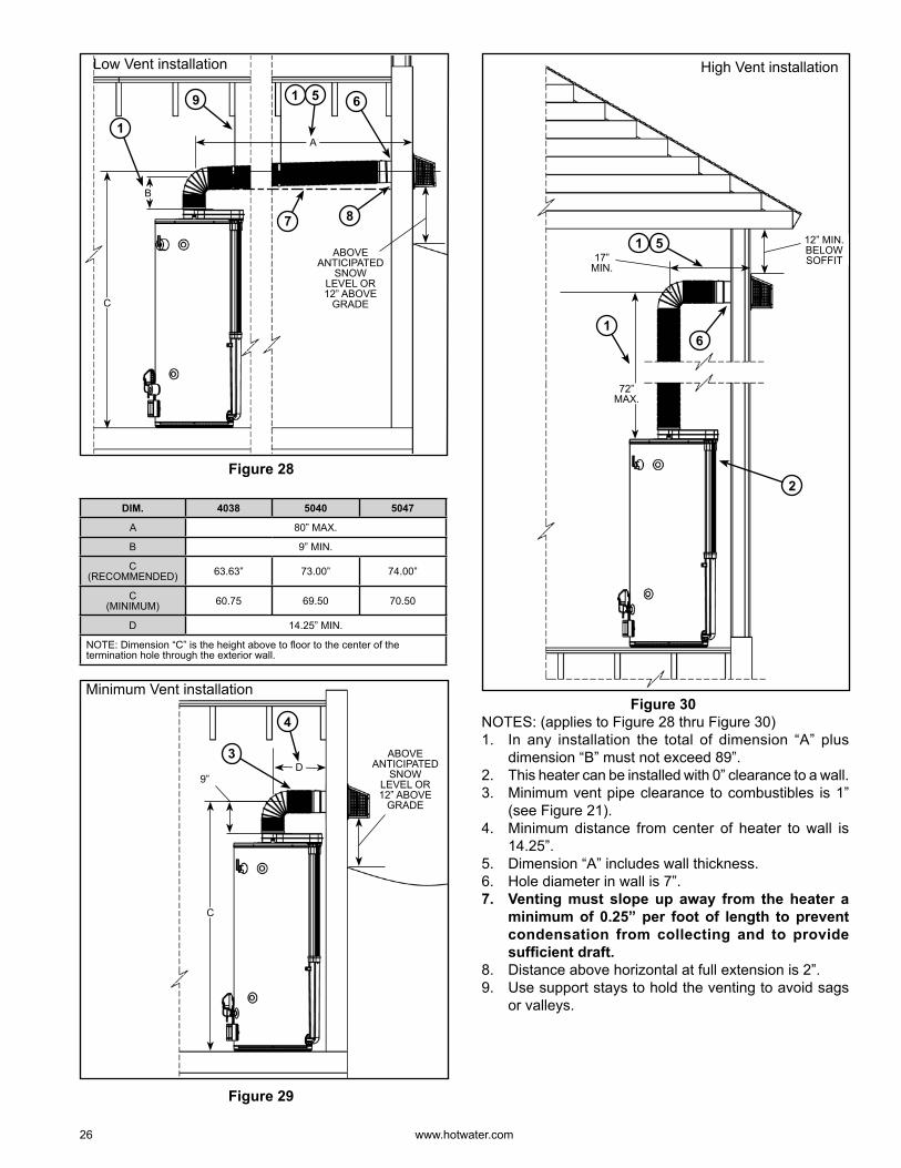
Figure 28
DIM. 4038 5040 5047
A 80” MAX.
B 9” MIN.
C (RECOMMENDED) 63.63” 73.00” 74.00”
C (MINIMUM) 60.75 69.50 70.50
D 14.25” MIN.
NOTE: Dimension “C” is the height above to fl oor to the center of the termination hole through the exterior wall.
D
4
Minimum Vent installation
C
ABOVE ANTICIPATED
SNOW LEVEL OR 12” ABOVE
GRADE
3
9”
Figure 29
12” MIN. BELOW SOFFIT
72” MAX.
6
2
High Vent installation
51
1
17” MIN.
Figure 30 NOTES: (applies to Figure 28 thru Figure 30)1. In any installation the total of dimension “A” plus
dimension “B” must not exceed 89” .2. This heater can be installed with 0” clearance to a wall.3. Minimum vent pipe clearance to combustibles is 1”
(see Figure 21).4. Minimum distance from center of heater to wall is
14.25” .5. Dimension “A” includes wall thickness.6. Hole diameter in wall is 7” .7. Venting must slope up away from the heater a
minimum of 0.25” per foot of length to prevent condensation from collecting and to provide suffi cient draft.
8. Distance above horizontal at full extension is 2” .9. Use support stays to hold the venting to avoid sags
or valleys.
www. hotwater .com 27
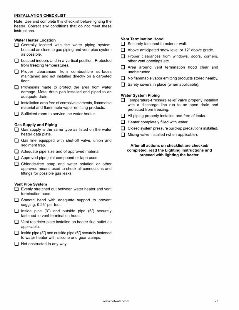
INSTALLATION CHECKLISTNote: Use and complete this checklist before lighting the heater. Correct any conditions that do not meet these instructions.
Water Heater Location Centrally located with the water piping system. Located as close to gas piping and vent pipe system as possible.
Located indoors and in a vertical position. Protected from freezing temperatures.
Proper clearances from combustible surfaces maintained and not installed directly on a carpeted floor.
Provisions made to protect the area from water damage. Metal drain pan installed and piped to an adequate drain.
Installation area free of corrosive elements, flammable material and flammable vapo r emitting products.
Sufficient room to service the water heater.
Gas Supply and Piping Gas supply is the same type as listed on the water heater data plate.
Gas line equipped with shut-off valve, union and sediment trap.
Adequate pipe size and of approved material.
Approved pipe joint compound or tape used.
Chloride-free soap and water solution or other approved means used to check all connections and fittings for possible gas leaks.
Vent Pipe System Evenly stretched out between water heater and vent termination hood.
Smooth bend with adequate support to prevent sagging, 0.25” per foot .
Inside pipe (3”) and outside pipe (6”) securely fastened to vent termination hood.
Vent restricter plate installed on heater flue outlet as applicable.
Inside pipe (3”) and outside pipe (6”) securely fastened to water heater with silicone and gear clamps.
Not obstructed in any way.
Vent Termination Hood Securely fastened to exterior wall.
Above anticipated snow level or 12” above grade.
Proper clearances from windows, doors, corners, other vent openings etc.
Area around vent termination hood clear and unobstructed.
No flammable vapo r emitting products stored nearby.
Safety covers in place (when applicable).
Water System Piping Temperature-Pressure relief valve properly installed with a discharge line run to an open drain and protected from freezing.
All piping properly installed and free of leaks.
Heater completely filled with water.
Closed system pressure build-up precautions installed.
Mixing valve installed (when applicable).
After all actions on checklist are checked/completed, read the Lighting Instructions and
proceed with lighting the heater.
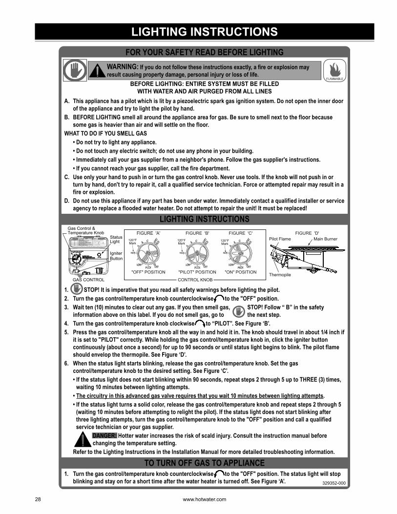
28 www. hotwater .com
LIGHTING INSTRUCTIONS
1. Turn the gas control/temperature knob counterclockwise to the "OFF" position. The status light will stop blinking and stay on for a short time after the water heater is turned off. See Figure ‘A’. 329352-000
TO TURN OFF GAS TO APPLIANCE
1. STOP! It is imperative that you read all safety warnings before lighting the pilot.2. Turn the gas control/temperature knob counterclockwise to the "OFF" position.3. Wait ten (10) minutes to clear out any gas. If you then smell gas, STOP! Follow “ B” in the safety
information above on this label. If you do not smell gas, go to the next step.4. Turn the gas control/temperature knob clockwise to “PILOT”. See Figure ‘B’.5. Press the gas control/temperature knob all the way in and hold it in. The knob should travel in about 1/4 inch if
it is set to "PILOT" correctly. While holding the gas control/temperature knob in, click the igniter button continuously (about once a second) for up to 90 seconds or until status light begins to blink. The pilot flame should envelop the thermopile. See Figure ‘D’.
6. When the status light starts blinking, release the gas control/temperature knob. Set the gas control/temperature knob to the desired setting. See Figure ‘C’.
• If the status light does not start blinking within 90 seconds, repeat steps 2 through 5 up to THREE (3) times, waiting 10 minutes between lighting attempts.
• The circuitry in this advanced gas valve requires that you wait 10 minutes between lighting attempts. • If the status light turns a solid color, release the gas control/temperature knob and repeat steps 2 through 5
(waiting 10 minutes before attempting to relight the pilot). If the status light does not start blinking after three lighting attempts, turn the gas control/temperature knob to the "OFF" position and call a qualified service technician or your gas supplier.
DANGER: Hotter water increases the risk of scald injury. Consult the instruction manual before changing the temperature setting.
Refer to the Lighting Instructions in the Installation Manual for more detailed troubleshooting information.
DANGER:
FIGURE 'D'Main Burner
Thermopile
Pilot FlameFIGURE 'A'
"OFF" POSITION
FIGURE 'B'
"PILOT" POSITION
FIGURE 'C'
"ON" POSITION
120°FMark
120°FMark
CONTROL KNOB
120°FMark
GAS CONTROL
Gas Control & Temperature Knob
StatusLight
IgniterButton
LIGHTING INSTRUCTIONS
A. This appliance has a pilot which is lit by a piezoelectric spark gas ignition system. Do not open the inner door of the appliance and try to light the pilot by hand.
B. BEFORE LIGHTING smell all around the appliance area for gas. Be sure to smell next to the floor because some gas is heavier than air and will settle on the floor.
WHAT TO DO IF YOU SMELL GAS • Do not try to light any appliance. • Do not touch any electric switch; do not use any phone in your building. • Immediately call your gas supplier from a neighbor's phone. Follow the gas supplier's instructions. • If you cannot reach your gas supplier, call the fire department.C. Use only your hand to push in or turn the gas control knob. Never use tools. If the knob will not push in or
turn by hand, don't try to repair it, call a qualified service technician. Force or attempted repair may result in a fire or explosion.
D. Do not use this appliance if any part has been under water. Immediately contact a qualified installer or service agency to replace a flooded water heater. Do not attempt to repair the unit! It must be replaced!
BEFORE LIGHTING: ENTIRE SYSTEM MUST BE FILLED WITH WATER AND AIR PURGED FROM ALL LINES
FLAMMABLE
WARNING: If you do not follow these instructions exactly, a fire or explosion may result causing property damage, personal injury or loss of life.
FOR YOUR SAFETY READ BEFORE LIGHTING
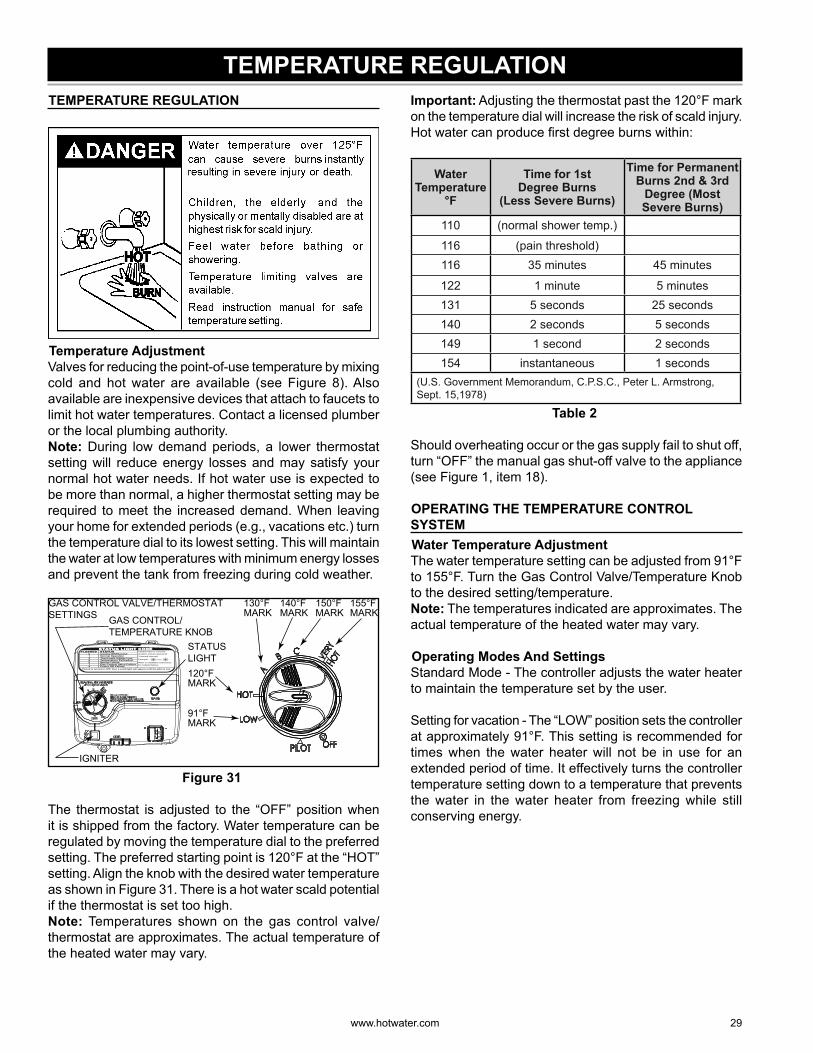
www. hotwater .com 29
TEMPERATURE REGULATION TEMPERATURE REGULATION
Temperature AdjustmentValves for reducing the point-of-use temperature by mixing cold and hot water are available (see Figure 8). Also available are inexpensive devices that attach to faucets to limit hot water temperatures. Contact a licensed plumber or the local plumbing authority.Note: During low demand periods, a lower thermostat setting will reduce energy losses and may satisfy your normal hot water needs. If hot water use is expected to be more than normal, a higher thermostat setting may be required to meet the increased demand. When leaving your home for extended periods (e.g., vacations etc.) turn the temperature dial to its lowest setting. This will maintain the water at low temperatures with minimum energy losses and prevent the tank from freezing during cold weather.
GAS CONTROL VALVE/THERMOSTAT SETTINGS GAS CONTROL/
TEMPERATURE KNOBSTATUS LIGHT
IGNITER
120°F MARK
130°F MARK
155°F MARK
150°F MARK
140°F MARK
91°F MARK
Figure 31
The thermostat is adjusted to the “OFF” position when it is shipped from the factory. Water temperature can be regulated by moving the temperature dial to the preferred setting. The preferred starting point is 120°F at the “HOT” setting. Align the knob with the desired water temperature as shown in Figure 31. There is a hot water scald potential if the thermostat is set too high.Note: Temperatures shown on the gas control valve/thermostat are approximates. The actual temperature of the heated water may vary.
Important: Adjusting the thermostat past the 120°F mark on the temperature dial will increase the risk of scald injury. Hot water can produce fi rst degree burns within:
Water Temperature
°F
Time for 1stDegree Burns
(Less Severe Burns)
Time for Permanent Burns 2nd & 3rd
Degree (Most Severe Burns)
110 (normal shower temp.)
116 (pain threshold) 116 35 minutes 45 minutes
122 1 minute 5 minutes 131 5 seconds 25 seconds 140 2 seconds 5 seconds 149 1 second 2 seconds 154 instantaneous 1 seconds
(U.S. Government Memorandum, C.P.S.C., Peter L. Armstrong, Sept. 15,1978)
Table 2
Should overheating occur or the gas supply fail to shut off, turn “OFF” the manual gas shut-off valve to the appliance (see Figure 1, item 18).
OPERATING THE TEMPERATURE CONTROL SYSTEM Water Temperature AdjustmentThe water temperature setting can be adjusted from 91°F to 155°F . Turn the Gas Control Valve/Temperature Knob to the desired setting/temperature.Note: The temperatures indicated are approximates. The actual temperature of the heated water may vary.
Operating Modes And SettingsStandard Mode - The controller adjusts the water heater to maintain the temperature set by the user.
Setting for vacation - The “LOW” position sets the controller at approximately 91°F . This setting is recommended for times when the water heater will not be in use for an extended period of time. It effectively turns the controller temperature setting down to a temperature that prevents the water in the water heater from freezing while still conserving energy.
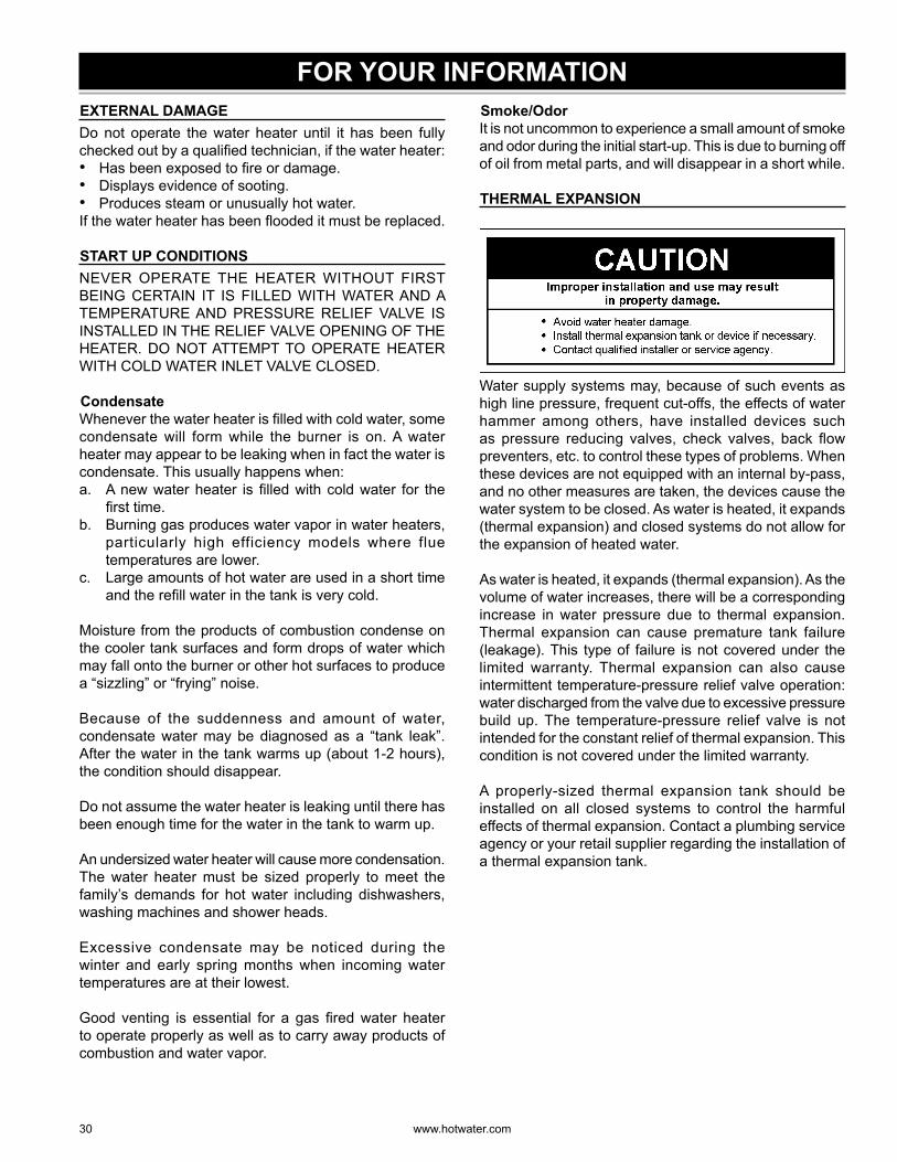
30 www. hotwater .com
FOR YOUR INFORMATION EXTERNAL DAMAGEDo not operate the water heater until it has been fully checked out by a qualifi ed technician, if the water heater:• Has been exposed to fi re or damage.• Displays evidence of sooting.• Produces steam or unusually hot water.If the water heater has been fl ooded it must be replaced.
START UP CONDITIONSNEVER OPERATE THE HEATER WITHOUT FIRST BEING CERTAIN IT IS FILLED WITH WATER AND A TEMPERATURE AND PRESSURE RELIEF VALVE IS INSTALLED IN THE RELIEF VALVE OPENING OF THE HEATER. DO NOT ATTEMPT TO OPERATE HEATER WITH COLD WATER INLET VALVE CLOSED.
CondensateWhenever the water heater is fi lled with cold water, some condensate will form while the burner is on. A water heater may appear to be leaking when in fact the water is condensate. This usually happens when:a. A new water heater is fi lled with cold water for the
fi rst time.b. Burning gas produces water vapo r in water heaters,
particularly high efficiency models where flue temperatures are lower.
c. Large amounts of hot water are used in a short time and the refi ll water in the tank is very cold.
Moisture from the products of combustion condense on the cooler tank surfaces and form drops of water which may fall onto the burner or other hot surfaces to produce a “sizzling” or “frying” noise.
Because of the suddenness and amount of water, condensate water may be diagnosed as a “tank leak”. After the water in the tank warms up (about 1-2 hours), the condition should disappear.
Do not assume the water heater is leaking until there has been enough time for the water in the tank to warm up.
An undersized water heater will cause more condensation. The water heater must be sized properly to meet the family’s demands for hot water including dishwashers, washing machines and shower heads.
Excessive condensate may be noticed during the winter and early spring months when incoming water temperatures are at their lowest.
Good venting is essential for a gas fi red water heater to operate properly as well as to carry away products of combustion and water vapo r.
Smoke/Odo rIt is not uncommon to experience a small amount of smoke and odo r during the initial start-up. This is due to burning off of oil from metal parts, and will disappear in a short while.
THERMAL EXPANSION
Water supply systems may, because of such events as high line pressure, frequent cut-offs, the effects of water hammer among others, have installed devices such as pressure reducing valves, check valves, back fl ow preventers, etc. to control these types of problems. When these devices are not equipped with an internal by-pass, and no other measures are taken, the devices cause the water system to be closed. As water is heated, it expands (thermal expansion) and closed systems do not allow for the expansion of heated water.
As water is heated, it expands (thermal expansion). As the volume of water increases, there will be a corresponding increase in water pressure due to thermal expansion. Thermal expansion can cause premature tank failure (leakage). This type of failure is not covered under the limited warranty. Thermal expansion can also cause intermittent temperature-pressure relief valve operation: water discharged from the valve due to excessive pressure build up. The temperature-pressure relief valve is not intended for the constant relief of thermal expansion. This condition is not covered under the limited warranty.
A properly-sized thermal expansion tank should be installed on all closed systems to control the harmful effects of thermal expansion. Contact a plumbing service agency or your retail supplier regarding the installation of a thermal expansion tank.
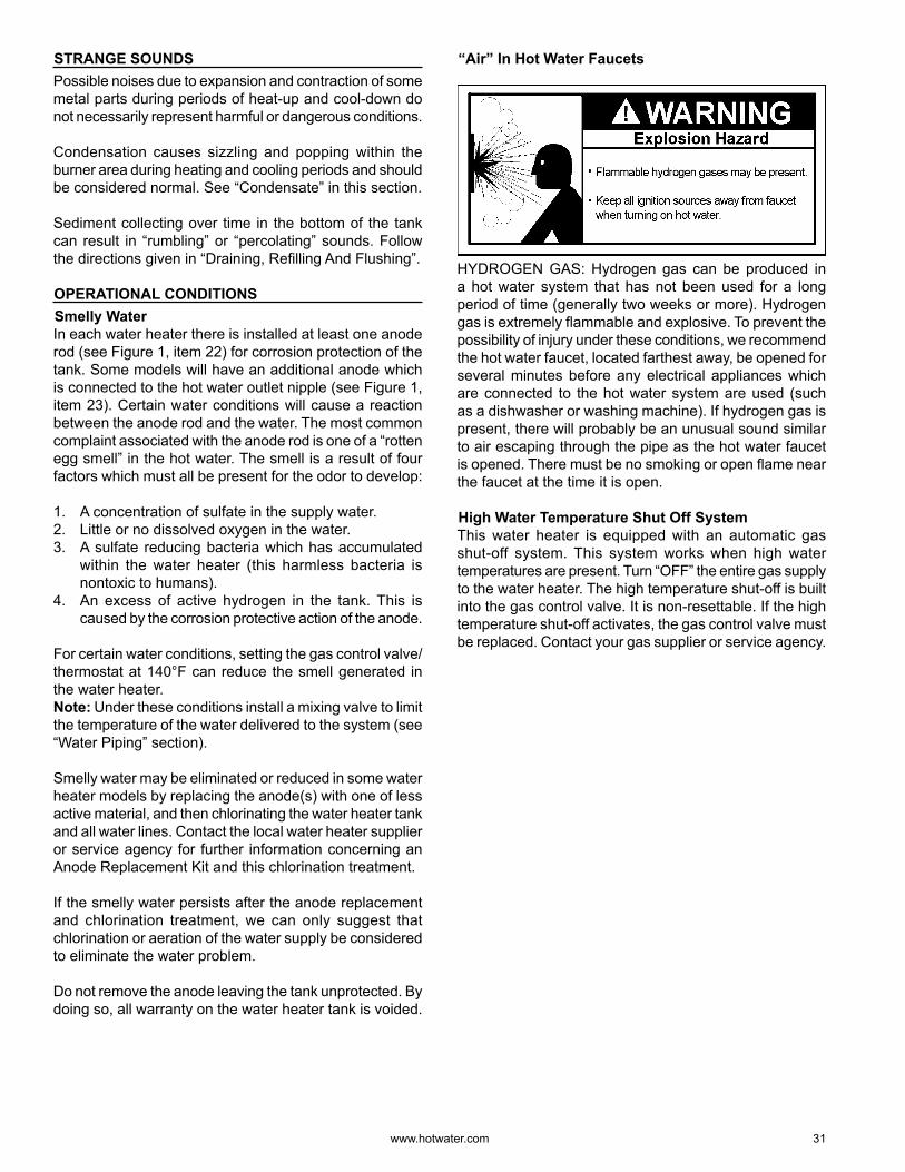
www. hotwater .com 31
STRANGE SOUNDSPossible noises due to expansion and contraction of some metal parts during periods of heat-up and cool-down do not necessarily represent harmful or dangerous conditions.
Condensation causes sizzling and popping within the burner area during heating and cooling periods and should be considered normal. See “Condensate” in this section.
Sediment collecting over time in the bottom of the tank can result in “rumbling” or “percolating” sounds. Follow the directions given in “Draining, Refi lling And Flushing”.
OPERATIONAL CONDITIONS Smelly WaterIn each water heater there is installed at least one anode rod (see Figure 1, item 22) for corrosion protection of the tank. Some models will have an additional anode which is connected to the hot water outlet nipple (see Figure 1, item 23). Certain water conditions will cause a reaction between the anode rod and the water. The most common complaint associated with the anode rod is one of a “rotten egg smell” in the hot water. The smell is a result of four factors which must all be present for the odo r to develop:
1. A concentration of sulfate in the supply water.2. Little or no dissolved oxygen in the water.3. A sulfate reducing bacteria which has accumulated
within the water heater (this harmless bacteria is nontoxic to humans).
4. An excess of active hydrogen in the tank. This is caused by the corrosion protective action of the anode.
For certain water conditions, setting the gas control valve/thermostat at 140°F can reduce the smell generated in the water heater.Note: Under these conditions install a mixing valve to limit the temperature of the water delivered to the system (see “Water Piping” section).
Smelly water may be eliminated or reduced in some water heater models by replacing the anode(s) with one of less active material, and then chlorinating the water heater tank and all water lines. Contact the local water heater supplier or service agency for further information concerning an Anode Replacement Kit and this chlorination treatment.
If the smelly water persists after the anode replacement and chlorination treatment, we can only suggest that chlorination or aeration of the water supply be considered to eliminate the water problem.
Do not remove the anode leaving the tank unprotected. By doing so, all warranty on the water heater tank is voided.
“Air” In Hot Water Faucets
HYDROGEN GAS: Hydrogen gas can be produced in a hot water system that has not been used for a long period of time (generally two weeks or more). Hydrogen gas is extremely fl ammable and explosive. To prevent the possibility of injury under these conditions, we recommend the hot water faucet, located farthest away, be opened for several minutes before any electrical appliances which are connected to the hot water system are used (such as a dishwasher or washing machine). If hydrogen gas is present, there will probably be an unusual sound similar to air escaping through the pipe as the hot water faucet is opened. There must be no smoking or open fl ame near the faucet at the time it is open.
High Water Temperature Shut Off SystemThis water heater is equipped with an automatic gas shut-off system. This system works when high water temperatures are present. Turn “OFF” the entire gas supply to the water heater. The high temperature shut-off is built into the gas control valve. It is non-resettable. If the high temperature shut-off activates, the gas control valve must be replaced. Contact your gas supplier or service agency.
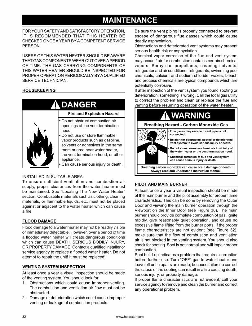
32 www. hotwater .com
MAINTENANCEFOR YOUR SAFETY AND SATISFACTORY OPERATION, IT IS RECOMMENDED THAT THIS HEATER BE CHECKED ONCE A YEAR BY A COMPETENT SERVICE PERSON.
USERS OF THIS WATER HEATER SHOULD BE AWARE THAT GAS COMPONENTS WEAR OUT OVER A PERIOD OF TIME. THE GAS CARRYING COMPONENTS OF THIS WATER HEATER SHOULD BE INSPECTED FOR PROPER OPERATION PERIODICALLY BY A QUALIFIED SERVICE TECHNICIAN.
HOUSEKEEPING
• Do not obstruct combustion air openings at the vent termination hood.
• Do not use or store flammable vapor products such as gasoline, solvents or adhesives in the same room or area near water heater, the vent termination hood, or other appliance.
• Can cause serious injury or death.
Fire and Explosion Hazard
DANGER
INSTALLED IN SUITABLE AREA:To ensure sufficient ventilation and combustion air supply, proper clearances from the water heater must be maintained. See “Locating The New Water Heater” section. Combustible materials such as clothing, cleaning materials, or fl ammable liquids, etc. must not be placed against or adjacent to the water heater which can cause a fi re.
FLOOD DAMAGEFlood damage to a water heater may not be readily visible or immediately detectable. However, over a period of time a fl ooded water heater will create dangerous conditions which can cause DEATH, SERIOUS BODILY INJURY, OR PROPERTY DAMAGE. Contact a qualifi ed installer or service agency to replace a fl ooded water heater. Do not attempt to repair the unit! It must be replaced!
VENTING SYSTEM INSPECTIONAt least once a year a visual inspection should be made of the venting system. You should look for:1. Obstructions which could cause improper venting.
The combustion and ventilation air fl ow must not be obstructed.
2. Damage or deterioration which could cause improper venting or leakage of combustion products.
Be sure the vent piping is properly connected to prevent escape of dangerous fl ue gasses which could cause deadly asphyxiation.Obstructions and deteriorated vent systems may present serious health risk or asphyxiation.Chemical vapo r corrosion of the fl ue and vent system may occur if air for combustion contains certain chemical vapo rs. Spray can propellants, cleaning solvents, refrigerator and air conditioner refrigerants, swimming pool chemicals, calcium and sodium chloride, waxes, bleach and process chemicals are typical compounds which are potentially corrosive.If after inspection of the vent system you found sooting or deterioration, something is wrong. Call the local gas utility to correct the problem and clean or replace the fl ue and venting before resuming operation of the water heater.
Breathing carbon monoxide can cause brain damage or death. Always read and understand instruction manual.
• Flue gases may escape if vent pipe is not connected.
• Be alert for obstructed, sooted or deteriorated vent system to avoid serious injury or death.
• Do not store corrosive chemicals in vicinity of the water heater or the vent termination hood.
• Chemical corrosion of flue and vent system can cause serious injury or death.
Breathing Hazard - Carbon Monoxide Gas
WARNING
PILOT AND MAIN BURNERAt least once a year a visual inspection should be made of the main burner and the pilot assembly for proper fl ame characteristics. This can be done by removing the Outer Door and viewing the main burner operation through the Viewport on the Inner Door (see Figure 38). The main burner should provide complete combustion of gas, ignite rapidly, give reasonably quiet operation, and cause no excessive fl ame lifting from the burner ports. If the proper fl ame characteristics are not evident (see Figure 32), make sure that the fl ow of combustion and ventilation air is not blocked in the venting system. You should also check for sooting. Soot is not normal and will impair proper combustion.Soot build-up indicates a problem that requires correction before further use. Turn “OFF” gas to water heater and leave off until repairs are made, because failure to correct the cause of the sooting can result in a fi re causing death, serious injury, or property damage.If proper fl ame characteristics are not evident, call your service agency to remove and clean the burner and correct any operational problem.
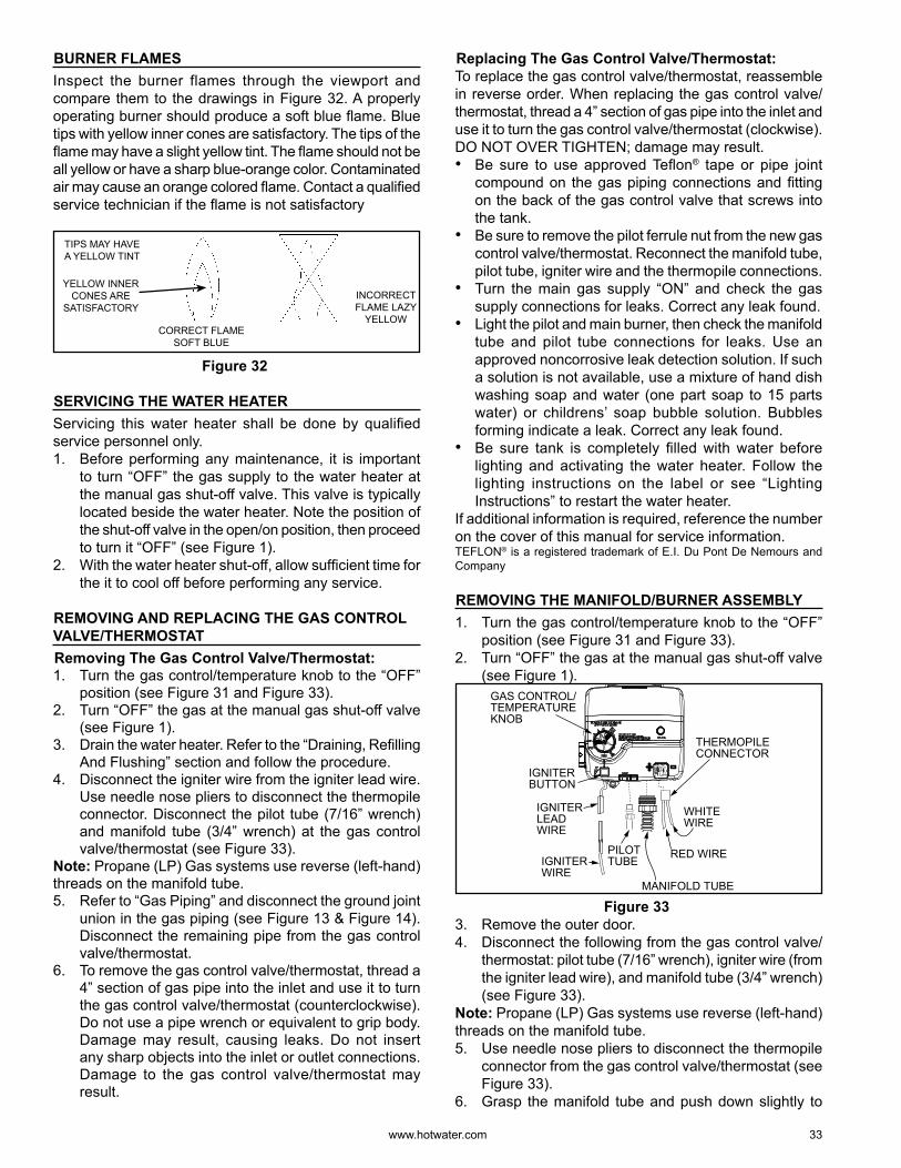
www. hotwater .com 33
BURNER FLAMESInspect the burner flames through the viewport and compare them to the drawings in Figure 32. A properly operating burner should produce a soft blue fl ame. Blue tips with yellow inner cones are satisfactory. The tips of the fl ame may have a slight yellow tint. The fl ame should not be all yellow or have a sharp blue-orange colo r. Contaminated air may cause an orange colo red fl ame. Contact a qualifi ed service technician if the fl ame is not satisfactory
CORRECT FLAME SOFT BLUE
INCORRECT FLAME LAZY
YELLOW
TIPS MAY HAVE A YELLOW TINT
YELLOW INNER CONES ARE
SATISFACTORY
Figure 32
SERVICING THE WATER HEATERServicing this water heater shall be done by qualifi ed service personnel only.1. Before performing any maintenance, it is important
to turn “OFF” the gas supply to the water heater at the manual gas shut-off valve. This valve is typically located beside the water heater. Note the position of the shut-off valve in the open/on position, then proceed to turn it “OFF” (see Figure 1).
2. With the water heater shut-off, allow suffi cient time for the it to cool off before performing any service.
REMOVING AND REPLACING THE GAS CONTROL VALVE/THERMOSTAT Removing The Gas Control Valve/Thermostat:1. Turn the gas control/temperature knob to the “OFF”
position (see Figure 31 and Figure 33).2. Turn “OFF” the gas at the manual gas shut-off valve
(see Figure 1).3. Drain the water heater. Refer to the “Draining, Refi lling
And Flushing” section and follow the procedure.4. Disconnect the igniter wire from the igniter lead wire.
Use needle nose pliers to disconnect the thermopile connector. Disconnect the pilot tube (7/16” wrench) and manifold tube (3/4” wrench) at the gas control valve/thermostat (see Figure 33).
Note: Propane (LP) Gas systems use reverse (left-hand) threads on the manifold tube.5. Refer to “Gas Piping” and disconnect the ground joint
union in the gas piping (see Figure 13 & Figure 14). Disconnect the remaining pipe from the gas control valve/thermostat.
6. To remove the gas control valve/thermostat, thread a 4” section of gas pipe into the inlet and use it to turn the gas control valve/thermostat (counterclockwise). Do not use a pipe wrench or equivalent to grip body. Damage may result, causing leaks. Do not insert any sharp objects into the inlet or outlet connections. Damage to the gas control valve/thermostat may result.
Replacing The Gas Control Valve/Thermostat:To replace the gas control valve/thermostat, reassemble in reverse order. When replacing the gas control valve/thermostat, thread a 4” section of gas pipe into the inlet and use it to turn the gas control valve/thermostat (clockwise). DO NOT OVER TIGHTEN; damage may result.• Be sure to use approved Tefl on® tape or pipe joint
compound on the gas piping connections and fi tting on the back of the gas control valve that screws into the tank.
• Be sure to remove the pilot ferrule nut from the new gas control valve/thermostat. Reconnect the manifold tube, pilot tube, igniter wire and the thermopile connections.
• Turn the main gas supply “ON” and check the gas supply connections for leaks. Correct any leak found.
• Light the pilot and main burner, then check the manifold tube and pilot tube connections for leaks. Use an approved noncorrosive leak detection solution. If such a solution is not available, use a mixture of hand dish washing soap and water (one part soap to 15 parts water) or childrens’ soap bubble solution. Bubbles forming indicate a leak. Correct any leak found.
• Be sure tank is completely fi lled with water before lighting and activating the water heater. Follow the lighting instructions on the label or see “Lighting Instructions” to restart the water heater.
If additional information is required, reference the number on the cover of this manual for service information.TEFLON® is a registered trademark of E.I. Du Pont De Nemours and Company
REMOVING THE MANIFOLD/BURNER ASSEMBLY1. Turn the gas control/temperature knob to the “OFF”
position (see Figure 31 and Figure 33).2. Turn “OFF” the gas at the manual gas shut-off valve
(see Figure 1).
IGNITERWIRE
RED WIREPILOTTUBE
MANIFOLD TUBE
IGNITERBUTTON
IGNITERLEADWIRE
WHITEWIRE
GAS CONTROL/TEMPERATURE KNOB
THERMOPILE CONNECTOR
Figure 33 3. Remove the outer door.4. Disconnect the following from the gas control valve/
thermostat: pilot tube (7/16” wrench), igniter wire (from the igniter lead wire), and manifold tube (3/4” wrench) (see Figure 33).
Note: Propane (LP) Gas systems use reverse (left-hand) threads on the manifold tube.5. Use needle nose pliers to disconnect the thermopile
connector from the gas control valve/thermostat (see Figure 33).
6. Grasp the manifold tube and push down slightly to
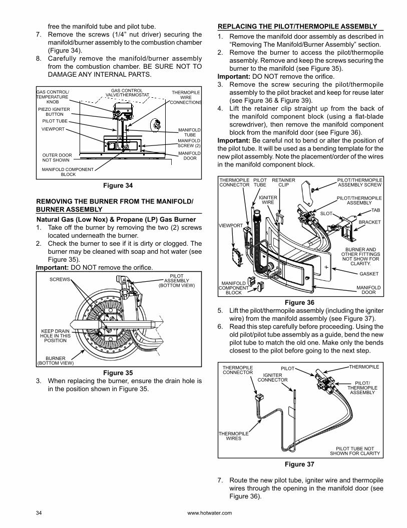
34 www. hotwater .com
free the manifold tube and pilot tube.7. Remove the screws (1/4” nut driver) securing the
manifold/burner assembly to the combustion chamber (Figure 34).
8. Carefully remove the manifold/burner assembly from the combustion chamber. BE SURE NOT TO DAMAGE ANY INTERNAL PARTS.
VIEWPORT
PILOT TUBE
MANIFOLD DOOR
MANIFOLD COMPONENT BLOCK
MANIFOLD TUBE
OUTER DOOR NOT SHOWN
MANIFOLDSCREW (2)
GAS CONTROL VALVE/THERMOSTAT THERMOPILE
WIRECONNECTIONS
GAS CONTROL/TEMPERATURE
KNOB
PIEZO IGNITER BUTTON
Figure 34
REMOVING THE BURNER FROM THE MANIFOLD/BURNER ASSEMBLY Natural Gas (Low Nox) & Propane (LP) Gas Burner1. Take off the burner by removing the two (2) screws
located underneath the burner.2. Check the burner to see if it is dirty or clogged. The
burner may be cleaned with soap and hot water (see Figure 35).
Important: DO NOT remove the orifi ce.
SCREWS
BURNER (BOTTOM VIEW)
PILOT ASSEMBLY
(BOTTOM VIEW)
KEEP DRAIN HOLE IN THIS
POSITION
Figure 35 3. When replacing the burner, ensure the drain hole is
in the position shown in Figure 35.
REPLACING THE PILOT/THERMOPILE ASSEMBLY1. Remove the manifold door assembly as described in
“Removing The Manifold/Burner Assembly” section.2. Remove the burner to access the pilot/thermopile
assembly. Remove and keep the screws securing the burner to the manifold (see Figure 35).
Important: DO NOT remove the orifi ce.3. Remove the screw securing the pilot/thermopile
assembly to the pilot bracket and keep for reuse later (see Figure 36 & Figure 39).
4. Lift the retainer clip straight up from the back of the manifold component block (using a fl at-blade screwdriver), then remove the manifold component block from the manifold door (see Figure 36).
Important: Be careful not to bend or alter the position of the pilot tube. It will be used as a bending template for the new pilot assembly. Note the placement/order of the wires in the manifold component block.
BURNER AND OTHER FITTINGS NOT SHOW FOR
CLARITY.
PILOT/THERMOPILE ASSEMBLY SCREW
THERMOPILE CONNECTOR
PILOT TUBE
IGNITER WIRE
MANIFOLD COMPONENT
BLOCK
RETAINER CLIP
MANIFOLD DOOR
PILOT/THERMOPILE ASSEMBLY
GASKET
TAB
BRACKET
SLOT
VIEWPORT
Figure 36 5. Lift the pilot/thermopile assembly (including the igniter
wire) from the manifold assembly (see Figure 37).6. Read this step carefully before proceeding. Using the
old pilot/pilot tube assembly as a guide, bend the new pilot tube to match the old one. Make only the bends closest to the pilot before going to the next step.
THERMOPILE WIRES
THERMOPILE CONNECTOR
PILOT TUBE NOT SHOWN FOR CLARITY
IGNITER CONNECTOR
PILOT/THERMOPILE
ASSEMBLY
THERMOPILEPILOT
Figure 37
7. Route the new pilot tube, igniter wire and thermopile wires through the opening in the manifold door (see Figure 36).
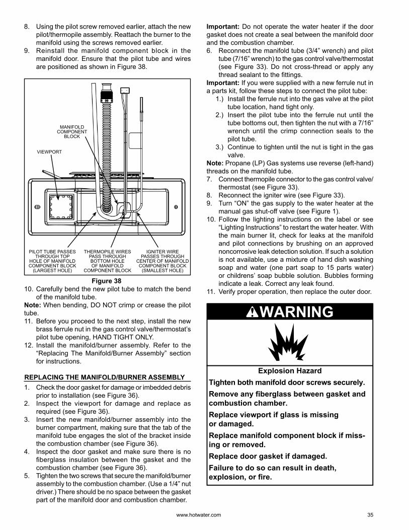
www. hotwater .com 35
8. Using the pilot screw removed earlier, attach the new pilot/thermopile assembly. Reattach the burner to the manifold using the screws removed earlier.
9. Reinstall the manifold component block in the manifold door. Ensure that the pilot tube and wires are positioned as shown in Figure 38.
MANIFOLDCOMPONENT
BLOCK
PILOT TUBE PASSES THROUGH TOP
HOLE OF MANIFOLD COMPONENT BLOCK
(LARGEST HOLE)
IGNITER WIRE PASSES THROUGH
CENTER OF MANIFOLD COMPONENT BLOCK
(SMALLEST HOLE)
THERMOPILE WIRES PASS THROUGH BOTTOM HOLE OF MANIFOLD
COMPONENT BLOCK
VIEWPORT
Figure 38 10. Carefully bend the new pilot tube to match the bend
of the manifold tube.Note: When bending, DO NOT crimp or crease the pilot tube.11. Before you proceed to the next step, install the new
brass ferrule nut in the gas control valve/thermostat’s pilot tube opening, HAND TIGHT ONLY.
12. Install the manifold/burner assembly. Refer to the “Replacing The Manifold/Burner Assembly” section for instructions.
REPLACING THE MANIFOLD/BURNER ASSEMBLY1. Check the door gasket for damage or imbedded debris
prior to installation (see Figure 36).2. Inspect the viewport for damage and replace as
required (see Figure 36).3. Insert the new manifold/burner assembly into the
burner compartment, making sure that the tab of the manifold tube engages the slot of the bracket inside the combustion chamber (see Figure 36).
4. Inspect the door gasket and make sure there is no fi berglass insulation between the gasket and the combustion chamber (see Figure 36).
5. Tighten the two screws that secure the manifold/burner assembly to the combustion chamber. (Use a 1/4” nut driver.) There should be no space between the gasket part of the manifold door and combustion chamber.
Important: Do not operate the water heater if the door gasket does not create a seal between the manifold door and the combustion chamber.6. Reconnect the manifold tube (3/4” wrench) and pilot
tube (7/16” wrench) to the gas control valve/thermostat (see Figure 33). Do not cross-thread or apply any thread sealant to the fi ttings.
Important: If you were supplied with a new ferrule nut in a parts kit, follow these steps to connect the pilot tube:
1.) Install the ferrule nut into the gas valve at the pilot tube location, hand tight only.
2.) Insert the pilot tube into the ferrule nut until the tube bottoms out, then tighten the nut with a 7/16” wrench until the crimp connection seals to the pilot tube.
3.) Continue to tighten until the nut is tight in the gas valve.
Note: Propane (LP) Gas systems use reverse (left-hand) threads on the manifold tube.7. Connect thermopile connector to the gas control valve/
thermostat (see Figure 33).8. Reconnect the igniter wire (see Figure 33).9. Turn “ON” the gas supply to the water heater at the
manual gas shut-off valve (see Figure 1).10. Follow the lighting instructions on the label or see
“Lighting Instructions” to restart the water heater. With the main burner lit, check for leaks at the manifold and pilot connections by brushing on an approved noncorrosive leak detection solution. If such a solution is not available, use a mixture of hand dish washing soap and water (one part soap to 15 parts water) or childrens’ soap bubble solution. Bubbles forming indicate a leak. Correct any leak found.
11. Verify proper operation, then replace the outer door.
Explosion HazardTighten both manifold door screws securely.Remove any fiberglass between gasket andcombustion chamber.Replace viewport if glass is missingor damaged.Replace manifold component block if miss-ing or removed.Replace door gasket if damaged.Failure to do so can result in death,explosion, or fire.
WARNING
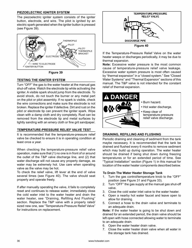
36 www. hotwater .com
PIEZOELECTRIC IGNITER SYSTEMThe piezoelectric igniter system consists of the igniter button, electrode, and wire. The pilot is ignited by an electric spark generated when the igniter button is pressed (see Figure 39).
PILOT/THERMOPILEBRACKET
ELECTRODE
THERMOPILE
PILOT
IGNITER BUTTONWIRE TO ELECTRODE
Figure 39
TESTING THE IGNITER SYSTEMTurn “OFF” the gas to the water heater at the manual gas shut-off valve. Watch the electrode tip while activating the igniter. A visible spark should jump from the electrode. To avoid shock, do not touch the burner or any metal part on the pilot or pilot assembly. If no spark is visible, check the wire connections and make sure the electrode is not broken. Replace the igniter if defective. Dirt and rust on the pilot or electrode tip can prevent the igniter spark. Wipe clean with a damp cloth and dry completely. Rust can be removed from the electrode tip and metal surfaces by lightly sanding with an emery cloth or fi ne grit sandpaper.
TEMPERATURE-PRESSURE RELIEF VALVE TESTIt is recommended that the temperature-pressure relief valve be checked to ensure it is in operating condition at least once a year.
When checking the temperature-pressure relief valve operation, make sure that (1) no one is in front of or around the outlet of the T&P valve discharge line, and (2) that water discharge will not cause any property damage, as water may be extremely hot. Use care when operating valve as the valve may be hot.To check the relief valve, lift lever at the end of valve several times (see Figure 40). The valve should seat properly and operate freely.
If after manually operating the valve, it fails to completely reset and continues to release water, immediately close the cold water inlet to the water heater and drain the water heater, see “Draining, Refilling And Flushing” section. Replace the T&P valve with a properly rated/sized new one, see “Temperature-Pressure Relief Valve” for instructions on replacement.
Figure 40
If the Temperature-Pressure Relief Valve on the water heater weeps or discharges periodically, it may be due to thermal expansion.Note: Excessive water pressure is the most common cause of temperature-pressure relief valve leakage. Excessive water system pressure is most often caused by “thermal expansion” in a “closed system.” See “Closed Water Systems” and “Thermal Expansion” sections of this manual. The T&P valve is not intended for the constant relief of thermal expansion.
• Burn hazard.• Hot water discharge.• Keep clear of
temperature-pressure relief valve discharge.
BURN
HOTHOT
DANGER
DRAINING, REFILLING AND FLUSHINGPeriodic draining and cleaning of sediment from the tank maybe necessary. It is recommended that the tank be drained and fl ushed every 6 months to remove sediment which may build up during operation. The water heater should be drained if being shut down during freezing temperatures or for an extended period of time. See “Typical Installation” section (Figure 1) in this manual for location of the water heater components described below.
To Drain The Water Heater Storage Tank1. Turn the gas control/temperature knob to the “OFF”
position (see Figure 31 and Figure 33).2. Turn “OFF” the gas supply at the manual gas shut-off
valve.3. Close the cold water inlet valve to the water heater.4. Open a nearby hot water faucet and leave open to
allow for draining.5. Connect a hose to the drain valve and terminate to
an adequate drain.Note: If the water heater is going to be shut down and drained for an extended period, the drain valve should be left open with hose connected allowing water to terminate to an adequate drain.6. Open the water heater drain valve.7. Close the water heater drain valve when all water in
the storage tank has drained.
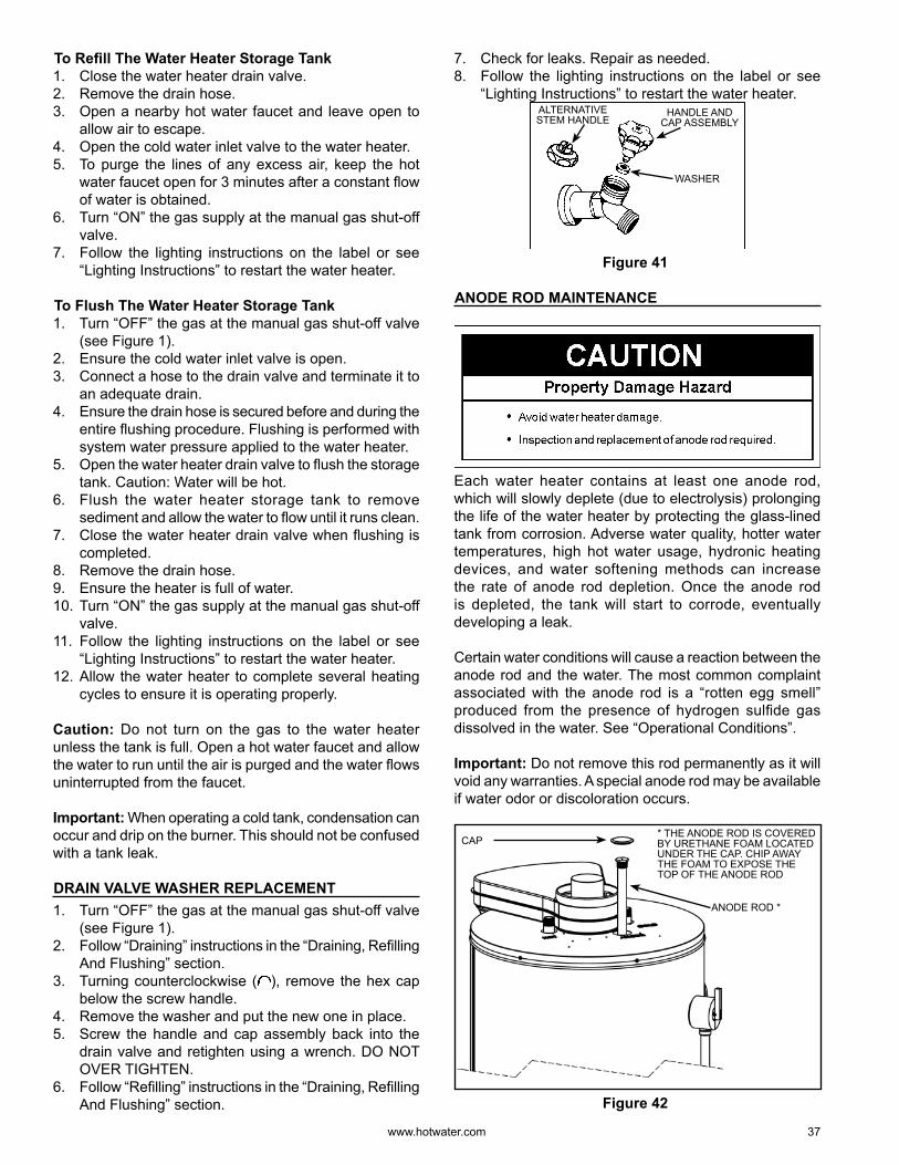
www. hotwater .com 37
To Refi ll The Water Heater Storage Tank1. Close the water heater drain valve.2. Remove the drain hose.3. Open a nearby hot water faucet and leave open to
allow air to escape.4. Open the cold water inlet valve to the water heater.5. To purge the lines of any excess air, keep the hot
water faucet open for 3 minutes after a constant fl ow of water is obtained.
6. Turn “ON” the gas supply at the manual gas shut-off valve.
7. Follow the lighting instructions on the label or see “Lighting Instructions” to restart the water heater.
To Flush The Water Heater Storage Tank1. Turn “OFF” the gas at the manual gas shut-off valve
(see Figure 1).2. Ensure the cold water inlet valve is open.3. Connect a hose to the drain valve and terminate it to
an adequate drain.4. Ensure the drain hose is secured before and during the
entire fl ushing procedure. Flushing is performed with system water pressure applied to the water heater.
5. Open the water heater drain valve to fl ush the storage tank. Caution: Water will be hot.
6. Flush the water heater storage tank to remove sediment and allow the water to fl ow until it runs clean.
7. Close the water heater drain valve when fl ushing is completed.
8. Remove the drain hose.9. Ensure the heater is full of water.10. Turn “ON” the gas supply at the manual gas shut-off
valve.11. Follow the lighting instructions on the label or see
“Lighting Instructions” to restart the water heater.12. Allow the water heater to complete several heating
cycles to ensure it is operating properly.
Caution: Do not turn on the gas to the water heater unless the tank is full. Open a hot water faucet and allow the water to run until the air is purged and the water fl ows uninterrupted from the faucet.
Important: When operating a cold tank, condensation can occur and drip on the burner. This should not be confused with a tank leak.
DRAIN VALVE WASHER REPLACEMENT1. Turn “OFF” the gas at the manual gas shut-off valve
(see Figure 1).2. Follow “Draining” instructions in the “Draining, Refi lling
And Flushing” section.3. Turning counterclockwise ( ), remove the hex cap
below the screw handle.4. Remove the washer and put the new one in place.5. Screw the handle and cap assembly back into the
drain valve and retighten using a wrench. DO NOT OVER TIGHTEN.
6. Follow “Refi lling” instructions in the “Draining, Refi lling And Flushing” section.
7. Check for leaks. Repair as needed.8. Follow the lighting instructions on the label or see
“Lighting Instructions” to restart the water heater.HANDLE AND
CAP ASSEMBLYALTERNATIVE STEM HANDLE
WASHER
Figure 41
ANODE ROD MAINTENANCE
Each water heater contains at least one anode rod, which will slowly deplete (due to electrolysis) prolonging the life of the water heater by protecting the glass-lined tank from corrosion. Adverse water quality, hotter water temperatures, high hot water usage, hydronic heating devices, and water softening methods can increase the rate of anode rod depletion. Once the anode rod is depleted, the tank will start to corrode, eventually developing a leak.
Certain water conditions will cause a reaction between the anode rod and the water. The most common complaint associated with the anode rod is a “rotten egg smell” produced from the presence of hydrogen sulfi de gas dissolved in the water. See “Operational Conditions”.
Important: Do not remove this rod permanently as it will void any warranties. A special anode rod may be available if water odo r or discolo ration occurs.
CAP
ANODE ROD *
* THE ANODE ROD IS COVERED BY URETHANE FOAM LOCATED UNDER THE CAP. CHIP AWAY THE FOAM TO EXPOSE THE TOP OF THE ANODE ROD
Figure 42
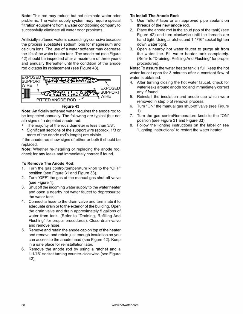
38 www. hotwater .com
Note: This rod may reduce but not eliminate water odo r problems. The water supply system may require special fi ltration equipment from a water conditioning company to successfully eliminate all water odo r problems.
Artifi cially softened water is exceedingly corrosive because the process substitutes sodium ions for magnesium and calcium ions. The use of a water softener may decrease the life of the water heater tank. The anode rod (see Figure 42) should be inspected after a maximum of three years and annually thereafter until the condition of the anode rod dictates its replacement (see Figure 43).
EXPOSED SUPPORT WIRE
PITTED ANODE ROD
EXPOSED SUPPORT WIRE
Figure 43 Note: Artifi cially softened water requires the anode rod to be inspected annually. The following are typical (but not all) signs of a depleted anode rod:• The majority of the rods diameter is less than 3/8” .• Signifi cant sections of the support wire (approx. 1/3 or
more of the anode rod’s length) are visible.If the anode rod show signs of either or both it should be replaced.Note: Whether re-installing or replacing the anode rod, check for any leaks and immediately correct if found.
To Remove The Anode Rod:1. Turn the gas control/temperature knob to the “OFF”
position (see Figure 31 and Figure 33).2. Turn “OFF” the gas at the manual gas shut-off valve
(see Figure 1).3. Shut off the incoming water supply to the water heater
and open a nearby hot water faucet to depressurize the water tank.
4. Connect a hose to the drain valve and terminate it to adequate drain or to the exterior of the building. Open the drain valve and drain approximately 5 gallons of water from tank. (Refer to “Draining, Refi lling And Flushing” for proper procedures). Close drain valve and remove hose.
5. Remove and retain the anode cap on top of the heater and remove and retain just enough insulation so you can access to the anode head (see Figure 42). Keep in a safe place for reinstallation later.
6. Remove the anode rod by using a ratchet and a 1-1/16” socket turning counter-clockwise (see Figure 42).
To Install The Anode Rod:1. Use Tefl on® tape or an approved pipe sealant on
threads of the new anode rod.2. Place the anode rod in the spud (top of the tank) (see
Figure 42) and turn clockwise until the threads are hand tight. Using a ratchet and 1-1/16” socket tighten down water tight.
3. Open a nearby hot water faucet to purge air from the water line. Fill water heater tank completely. (Refer to “Draining, Refi lling And Flushing” for proper procedures).
Note: To assure the water heater tank is full, keep the hot water faucet open for 3 minutes after a constant fl ow of water is obtained.4. After turning closing the hot water faucet, check for
water leaks around anode rod and immediately correct any if found.
5. Reinstall the insulation and anode cap which were removed in step 5 of removal process.
6. Turn “ON” the manual gas shut-off valve (see Figure 1).
7. Turn the gas control/temperature knob to the “ON” position (see Figure 31 and Figure 33).
8. Follow the lighting instructions on the label or see “Lighting Instructions” to restart the water heater.
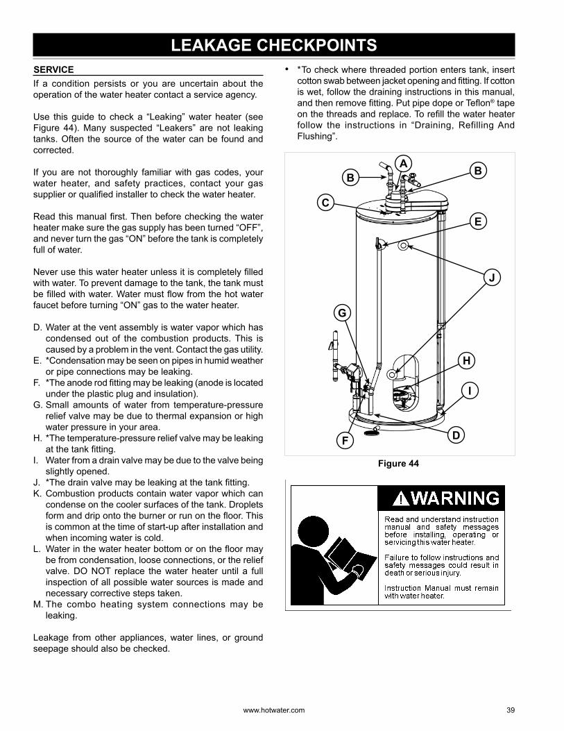
www. hotwater .com 39
LEAKAGE CHECKPOINTS SERVICEIf a condition persists or you are uncertain about the operation of the water heater contact a service agency.
Use this guide to check a “Leaking” water heater (see Figure 44). Many suspected “Leakers” are not leaking tanks. Often the source of the water can be found and corrected.
If you are not thoroughly familiar with gas codes, your water heater, and safety practices, contact your gas supplier or qualifi ed installer to check the water heater.
Read this manual fi rst. Then before checking the water heater make sure the gas supply has been turned “OFF”, and never turn the gas “ON” before the tank is completely full of water.
Never use this water heater unless it is completely fi lled with water. To prevent damage to the tank, the tank must be fi lled with water. Water must fl ow from the hot water faucet before turning “ON” gas to the water heater.
D. Water at the vent assembly is water vapo r which has condensed out of the combustion products. This is caused by a problem in the vent. Contact the gas utility.
E. *Condensation may be seen on pipes in humid weather or pipe connections may be leaking.
F. *The anode rod fi tting may be leaking (anode is located under the plastic plug and insulation).
G. Small amounts of water from temperature-pressure relief valve may be due to thermal expansion or high water pressure in your area.
H. *The temperature-pressure relief valve may be leaking at the tank fi tting.
I. Water from a drain valve may be due to the valve being slightly opened.
J. *The drain valve may be leaking at the tank fi tting.K. Combustion products contain water vapo r which can
condense on the cooler surfaces of the tank. Droplets form and drip onto the burner or run on the fl oor. This is common at the time of start-up after installation and when incoming water is cold.
L. Water in the water heater bottom or on the fl oor may be from condensation, loose connections, or the relief valve. DO NOT replace the water heater until a full inspection of all possible water sources is made and necessary corrective steps taken.
M. The combo heating system connections may be leaking.
Leakage from other appliances, water lines, or ground seepage should also be checked.
• * To check where threaded portion enters tank, insert cotton swab between jacket opening and fi tting. If cotton is wet, follow the draining instructions in this manual, and then remove fi tting. Put pipe dope or Tefl on® tape on the threads and replace. To refi ll the water heater follow the instructions in “Draining, Refilling And Flushing”.
F
G
I
H
D
E
AB B
C
J
Figure 44
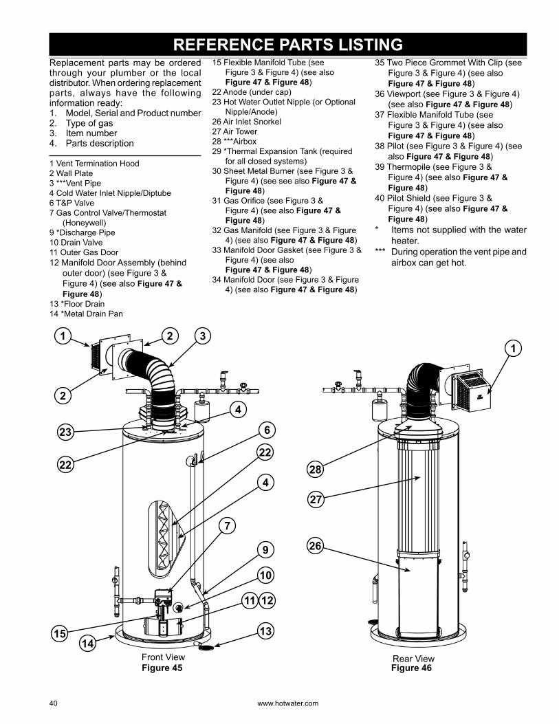
40 www. hotwater .com
REFERENCE PARTS LISTINGReplacement parts may be ordered through your plumber or the local distributor. When ordering replacement parts, always have the following information ready:1. Model, Serial and Product number2. Type of gas3. Item number4. Parts description
1 Vent Termination Hood2 Wall Plate3 ***Vent Pipe4 Cold Water Inlet Nipple/Diptube6 T&P Valve7 Gas Control Valve/Thermostat
(Honeywell)9 *Discharge Pipe10 Drain Valve11 Outer Gas Door12 Manifold Door Assembly (behind
outer door) (see Figure 3 & Figure 4) (see also Figure 47 & Figure 48)
13 *Floor Drain14 *Metal Drain Pan
15 Flexible Manifold Tube (see Figure 3 & Figure 4) (see also Figure 47 & Figure 48)
22 Anode (under cap)23 Hot Water Outlet Nipple (or Optional
Nipple/Anode)26 Air Inlet Snorkel27 Air Tower28 ***Airbox29 *Thermal Expansion Tank (required
for all closed systems)30 Sheet Metal Burner (see Figure 3 &
Figure 4) (see see also Figure 47 & Figure 48)
31 Gas Orifi ce (see Figure 3 & Figure 4) (see also Figure 47 & Figure 48)
32 Gas Manifold (see Figure 3 & Figure 4) (see also Figure 47 & Figure 48)
33 Manifold Door Gasket (see Figure 3 & Figure 4) (see also Figure 47 & Figure 48)
34 Manifold Door (see Figure 3 & Figure 4) (see also Figure 47 & Figure 48)
35 Two Piece Grommet With Clip (see Figure 3 & Figure 4) (see also Figure 47 & Figure 48)
36 Viewport (see Figure 3 & Figure 4) (see also Figure 47 & Figure 48)
37 Flexible Manifold Tube (see Figure 3 & Figure 4) (see also Figure 47 & Figure 48)
38 Pilot (see Figure 3 & Figure 4) (see also Figure 47 & Figure 48)
39 Thermopile (see Figure 3 & Figure 4) (see also Figure 47 & Figure 48)
40 Pilot Shield (see Figure 3 & Figure 4) (see also Figure 47 & Figure 48)
* Items not supplied with the water heater.
*** During operation the vent pipe and airbox can get hot.
23
1 32
6
4
9
10
1314
15
2
11 12
4
7
2222
Front ViewFigure 45 Figure 46
26
1
27
28
Rear View
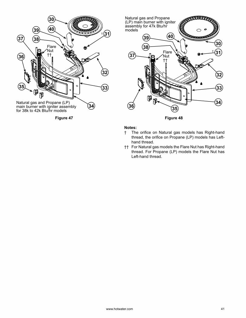
www. hotwater .com 41
Natural gas and Propane (LP) main burner with igniter assembly for 38k to 42k Btu/hr models
31
36
38
39
30
33
34
35
32
37
40
Flare Nut ††
†
Figure 47
37
Natural gas and Propane (LP) main burner with igniter assembly for 47k Btu/hr models
353634
33
32
31
4039
3830
Flare Nut ††
†
Figure 48
Notes:† The orifi ce on Natural gas models has Right-hand
thread, the orifi ce on Propane (LP) models has Left-hand thread.
†† For Natural gas models the Flare Nut has Right-hand thread. For Propane (LP) models the Flare Nut has Left-hand thread.
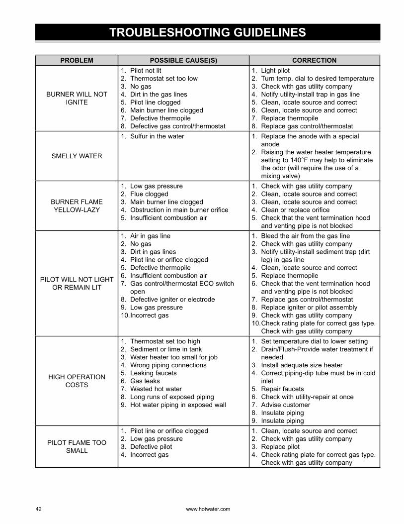
42 www. hotwater .com
TROUBLESHOOTING GUIDELINES
PROBLEM POSSIBLE CAUSE(S) CORRECTION
BURNER WILL NOT IGNITE
1. Pilot not lit2. Thermostat set too low3. No gas4. Dirt in the gas lines5. Pilot line clogged6. Main burner line clogged7. Defective thermopile8. Defective gas control/thermostat
1. Light pilot2. Turn temp. dial to desired temperature3. Check with gas utility company4. Notify utility-install trap in gas line5. Clean, locate source and correct6. Clean, locate source and correct7. Replace thermopile8. Replace gas control/thermostat
SMELLY WATER
1. Sulfur in the water 1. Replace the anode with a special anode
2. Raising the water heater temperature setting to 140°F may help to eliminate the odo r (will require the use of a mixing valve)
BURNER FLAME YELLOW-LAZY
1. Low gas pressure2. Flue clogged3. Main burner line clogged4. Obstruction in main burner orifice5. Insufficient combustion air
1. Check with gas utility company2. Clean, locate source and correct3. Clean, locate source and correct4. Clean or replace orifice5. Check that the vent termination hood
and venting pipe is not blocked
PILOT WILL NOT LIGHT OR REMAIN LIT
1. Air in gas line2. No gas3. Dirt in gas lines4. Pilot line or orifice clogged5. Defective thermopile6. Insufficient combustion air7. Gas control/thermostat ECO switch
open8. Defective igniter or electrode9. Low gas pressure10. Incorrect gas
1. Bleed the air from the gas line2. Check with gas utility company3. Notify utility-install sediment trap (dirt
leg) in gas line4. Clean, locate source and correct5. Replace thermopile6. Check that the vent termination hood
and venting pipe is not blocked7. Replace gas control/thermostat8. Replace igniter or pilot assembly9. Check with gas utility company10. Check rating plate for correct gas type.
Check with gas utility company
HIGH OPERATION COSTS
1. Thermostat set too high2. Sediment or lime in tank3. Water heater too small for job4. Wrong piping connections5. Leaking faucets6. Gas leaks7. Wasted hot water8. Long runs of exposed piping9. Hot water piping in exposed wall
1. Set temperature dial to lower setting2. Drain/Flush-Provide water treatment if
needed3. Install adequate size heater4. Correct piping-dip tube must be in cold
inlet5. Repair faucets6. Check with utility-repair at once7. Advise customer8. Insulate piping9. Insulate piping
PILOT FLAME TOO SMALL
1. Pilot line or orifice clogged2. Low gas pressure3. Defective pilot4. Incorrect gas
1. Clean, locate source and correct2. Check with gas utility company3. Replace pilot4. Check rating plate for correct gas type.
Check with gas utility company
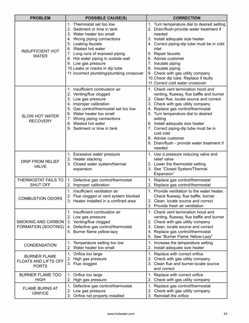
www. hotwater .com 43
PROBLEM POSSIBLE CAUSE(S) CORRECTION
INSUFFICIENT HOT WATER
1. Thermostat set too low2. Sediment or lime in tank3. Water heater too small4. Wrong piping connections5. Leaking faucets6. Wasted hot water7. Long runs of exposed piping8. Hot water piping in outside wall9. Low gas pressure10. Leaks or cracks in dip tube11. Incorrect plumbing/plumbing crossover
1. Turn temperature dial to desired setting2. Drain/flush-provide water treatment if
needed3. Install adequate size heater4. Correct piping-dip tube must be in cold
inlet5. Repair faucets6. Advise customer7. Insulate piping8. Insulate piping9. Check with gas utility company10. Check dip tube. Replace if faulty11. Correct cold water crossover
SLOW HOT WATER RECOVERY
1. Insufficient combustion air2. Venting/flue clogged3. Low gas pressure4. Improper calibration5. Gas control/thermostat set too low6. Water heater too small7. Wrong piping connections8. Wasted hot water9. Sediment or lime in tank
1. Check vent termination hood and venting, flueway, flue baffle and burner
2. Clean flue, locate source and correct3. Check with gas utility company4. Replace gas control/thermostat5. Turn temperature dial to desired
setting6. Install adequate size heater7. Correct piping-dip tube must be in
cold inlet8. Advise customer9. Drain/flush - provide water treatment if
needed
DRIP FROM RELIEF VALVE
1. Excessive water pressure2. Heater stacking3. Closed water system/thermal
expansion
1. Use a pressure reducing valve and relief valve
2. Lower the thermostat setting3. See “Closed System/Thermal
Expansion”THERMOSTAT FAILS TO
SHUT OFF1. Defective gas control/thermostat2. Improper calibration
1. Replace gas control/thermostat2. Replace gas control/thermostat
COMBUSTION ODO RS
1. Insufficient ventilation air2. Flue clogged or vent system blocked3. Heater installed in a confined area
1. Provide ventilation to the water heater. Check flueway, flue baffle, burner
2. Clean, locate source and correct3. Provide fresh air ventilation
SMOKING AND CARBON FORMATION (SOOTING)
1. Insufficient combustion air2. Low gas pressure3. Venting/flue clogged4. Defective gas control/thermostat5. Burner flame yellow-lazy
1. Check vent termination hood and venting, flueway, flue baffle and burner
2. Check with gas utility company3. Clean, locate source and correct4. Replace gas control/thermostat5. See “Burner Flame Yellow-Lazy”
CONDENSATION 1. Temperature setting too low2. Water heater too small
1. Increase the temperature setting2. Install adequate size heater
BURNER FLAME FLOATS AND LIFTS OFF
PORTS
1. Orifice too large2. High gas pressure3. Flue clogged
1. Replace with correct orifice2. Check with gas utility company3. Clean flue and burner-locate source
and correctBURNER FLAME TOO
HIGH1. Orifice too large2. High gas pressure
1. Replace with correct orifice2. Check with gas utility company
FLAME BURNS AT ORIFICE
1. Defective gas control/thermostat2. Low gas pressure3. Orifice not properly installed
1. Replace gas control/thermostat2. Check with gas utility company3. Reinstall the orifice
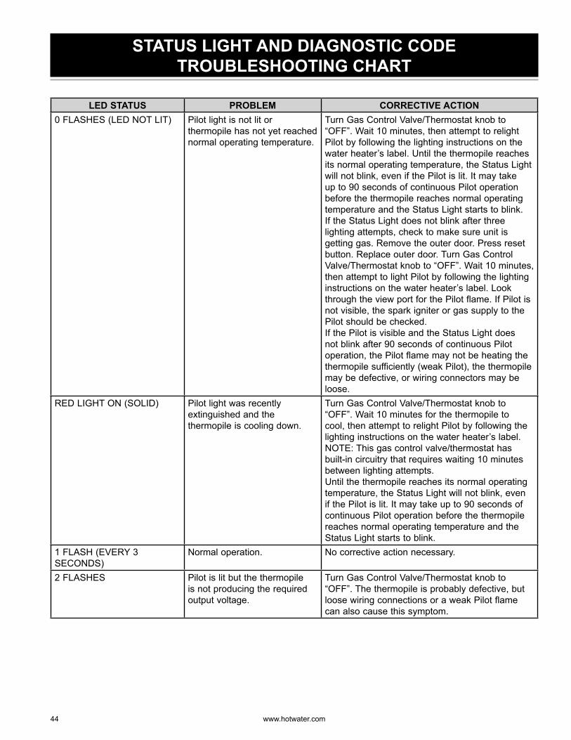
44 www. hotwater .com
STATUS LIGHT AND DIAGNOSTIC CODE TROUBLESHOOTING CHART
LED STATUS PROBLEM CORRECTIVE ACTION0 FLASHES (LED NOT LIT) Pilot light is not lit or
thermopile has not yet reached normal operating temperature.
Turn Gas Control Valve/Thermostat knob to “OFF”. Wait 10 minutes, then attempt to relight Pilot by following the lighting instructions on the water heater’s label. Until the thermopile reaches its normal operating temperature, the Status Light will not blink, even if the Pilot is lit. It may take up to 90 seconds of continuous Pilot operation before the thermopile reaches normal operating temperature and the Status Light starts to blink.If the Status Light does not blink after three lighting attempts, check to make sure unit is getting gas. Remove the outer door. Press reset button. Replace outer door. Turn Gas Control Valve/Thermostat knob to “OFF”. Wait 10 minutes, then attempt to light Pilot by following the lighting instructions on the water heater’s label. Look through the view port for the Pilot flame. If Pilot is not visible, the spark igniter or gas supply to the Pilot should be checked.If the Pilot is visible and the Status Light does not blink after 90 seconds of continuous Pilot operation, the Pilot flame may not be heating the thermopile sufficiently (weak Pilot), the thermopile may be defective, or wiring connectors may be loose.
RED LIGHT ON (SOLID) Pilot light was recently extinguished and the thermopile is cooling down.
Turn Gas Control Valve/Thermostat knob to “OFF”. Wait 10 minutes for the thermopile to cool, then attempt to relight Pilot by following the lighting instructions on the water heater’s label. NOTE: This gas control valve/thermostat has built-in circuitry that requires waiting 10 minutes between lighting attempts.Until the thermopile reaches its normal operating temperature, the Status Light will not blink, even if the Pilot is lit. It may take up to 90 seconds of continuous Pilot operation before the thermopile reaches normal operating temperature and the Status Light starts to blink.
1 FLASH (EVERY 3 SECONDS)
Normal operation. No corrective action necessary.
2 FLASHES Pilot is lit but the thermopile is not producing the required output voltage.
Turn Gas Control Valve/Thermostat knob to “OFF”. The thermopile is probably defective, but loose wiring connections or a weak Pilot flame can also cause this symptom.
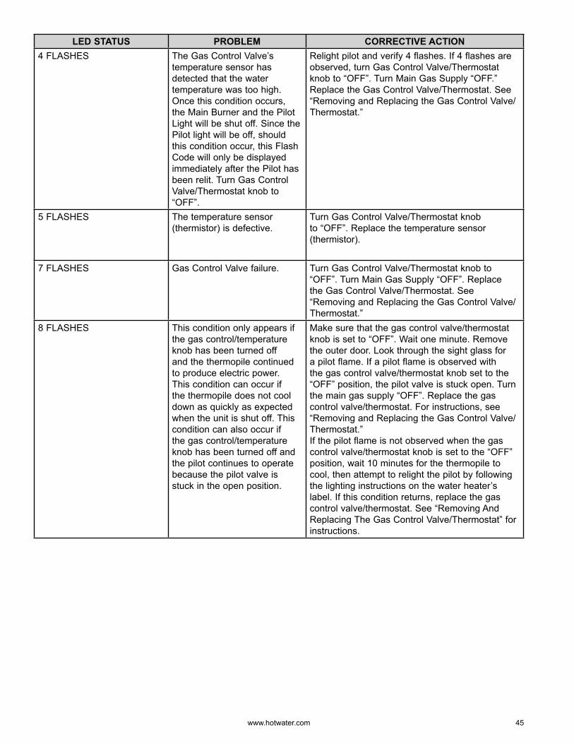
www. hotwater .com 45
LED STATUS PROBLEM CORRECTIVE ACTION4 FLASHES The Gas Control Valve’s
temperature sensor has detected that the water temperature was too high. Once this condition occurs, the Main Burner and the Pilot Light will be shut off. Since the Pilot light will be off, should this condition occur, this Flash Code will only be displayed immediately after the Pilot has been relit. Turn Gas Control Valve/Thermostat knob to “OFF”.
Relight pilot and verify 4 flashes. If 4 flashes are observed, turn Gas Control Valve/Thermostat knob to “OFF”. Turn Main Gas Supply “OFF.” Replace the Gas Control Valve/Thermostat. See “Removing and Replacing the Gas Control Valve/Thermostat.”
5 FLASHES The temperature sensor (thermistor) is defective.
Turn Gas Control Valve/Thermostat knob to “OFF”. Replace the temperature sensor (thermistor).
7 FLASHES Gas Control Valve failure. Turn Gas Control Valve/Thermostat knob to “OFF”. Turn Main Gas Supply “OFF”. Replace the Gas Control Valve/Thermostat. See “Removing and Replacing the Gas Control Valve/Thermostat.”
8 FLASHES This condition only appears if the gas control/temperature knob has been turned off and the thermopile continued to produce electric power. This condition can occur if the thermopile does not cool down as quickly as expected when the unit is shut off. This condition can also occur if the gas control/temperature knob has been turned off and the pilot continues to operate because the pilot valve is stuck in the open position.
Make sure that the gas control valve/thermostat knob is set to “OFF”. Wait one minute. Remove the outer door. Look through the sight glass for a pilot flame. If a pilot flame is observed with the gas control valve/thermostat knob set to the “OFF” position, the pilot valve is stuck open. Turn the main gas supply “OFF”. Replace the gas control valve/thermostat. For instructions, see “Removing and Replacing the Gas Control Valve/Thermostat.”If the pilot flame is not observed when the gas control valve/thermostat knob is set to the “OFF” position, wait 10 minutes for the thermopile to cool, then attempt to relight the pilot by following the lighting instructions on the water heater’s label. If this condition returns, replace the gas control valve/thermostat. See “Removing And Replacing The Gas Control Valve/Thermostat” for instructions.

46 www. hotwater .com
NOTES

www. hotwater .com 47
NOTES

500 Tennessee Waltz Parkway, Ashland City, TN 37015Phone: 800-527-1953 • Fax: 800-644-9306
www.hotwater.com