research inverted microscope - cairn research ltd · research inverted microscope this instruction...
TRANSCRIPT
IX73INSTRUCTIONS
RESEARCH INVERTED MICROSCOPE
This instruction manual is for the Olympus research inverted microscope model IX73.
To ensure the safety, obtain optimum performance and to familiarize yourself fully with the use
of this microscope, we recommend that you study this manual thoroughly before operating the
microscope.
Retain this instruction manual in an easily accessible place near the work desk for future reference.
A X 8 1 5 7

In accordance with European Directive 2002/96/EC on Waste Electrical and Electronic Equip-
ment, this symbol indicates that the product must not be disposed of as unsorted municipal
waste, but should be collected separately.
Refer to your local Olympus distributor in EU for return and/or collection systems available in
your country.

1 Intended use ...............................................................................................................................................................................................4
2 Conformity of the System ................................................................................................................................................................5
3 Handling Precautions..........................................................................................................................................................................6
4 Maintenance and Storage ..............................................................................................................................................................6
1 MODULE NOMENCLATURE .................................................................................................7
2 NOMENCLATURE ..........................................................................................................................8
3 TRANSMITTED LIGHT BRIGHTFIELD OBSERVATION PROCEDURE .12
4 USING THE CONTROLS ..........................................................................................................14
4-1 Power Supply Unit and Microscope Frame .......................................................................................14
1 Turning Power On, Adjusting the Brightness .................................................................................................................14
2 Light Path Selection ..............................................................................................................................................................................15
3 Coded intermediate magnification changer IX3-CAS ....................................................................................................... 15
4 Frame Fix Plate IX3-FP .......................................................................................................................................................................15
5 Dust tray ..........................................................................................................................................................................................................16
4-2 Focusing Block............................................................................................................................................................17
1 Rotation Direction of the Coarse/Fine Adjustment Knobs ..........................................................17
2 Adjusting the Coarse Adjustment Knob Tension .......................................................................................................17
3 Detaching the Fine Adjustment Knob ..................................................................................................................................17
4 Pre-focusing Lever .................................................................................................................................................................................17
4-3 Stage ....................................................................................................................................................................................18
1 Placing the Specimen ........................................................................................................................................................................18
2 Moving the Specimen.........................................................................................................................................................................21
3 Connecting the Grounding Wire ...............................................................................................................................................22
IMPORTANT -- Be sure to read this section for safe use of the equipment. -- 1-6
4-4 Observation Tube ......................................................................................................................................................23
1 Adjusting the Interpupillary Distance ....................................................................................................................................23
2 Adjusting the Diopter ...........................................................................................................................................................................23
3 Using the Eye Shades ........................................................................................................................................................................24
4 Mounting the Eyepiece Micrometer Disk ..........................................................................................................................24
5 Selecting the Light Path of the Trinocular Tube ...........................................................................................................24
6 Adjusting the Tilt (U-TBI90) .............................................................................................................................................................24
4-5 Illumination Column (IX3-ILL) ..........................................................................................................................25
1 Tilting the Illumination Column ...................................................................................................................................................25
2 Mounting Filters........................................................................................................................................................................................26
3 Using the Field Iris Diaphragm ...................................................................................................................................................27
4 Adjusting the Condenser Height Adjustment Knob Tension ...................................................................................................................27
5 Condenser refocusing stopper ..................................................................................................................................................27
4-6 Condenser ......................................................................................................................................................................28
1 Centering the Condenser ................................................................................................................................................................28
2 Using the Aperture Iris Diaphragm .........................................................................................................................................30
4-7 Oil- or Water-Immersion Objective ..........................................................................................................31
1 Using Oil- or Water-Immersion Objective .........................................................................................................................31
4-8 Objectives with Correction Collar ...............................................................................................................32
5 OTHER OBSERVATION METHODS .................................................................................33
5-1 Phase Contrast Observation ...........................................................................................................................33
1 Phase Contrast Optical Elements and Applicable Objectives .......................................................................33
2 Attaching the Phase Contrast Optical Elements ........................................................................................................34
3 Centering the Phase Contrast Ring Slit ..............................................................................................................................36
5-2 Differential Interference Contrast Observation ................................................................................37
1 DIC Optical Elements, Applicable Objectives and DIC Sliders ......................................................................37
2 Attaching the DIC Optical Elements ......................................................................................................................................38
3 Attaching the Analyzer and DIC Slider ................................................................................................................................39
4 Attaching the Polarizer (IX-LWPO) ............................................................................................................................................40
5 Cross-Nicol Adjustment ....................................................................................................................................................................41
6 Observation Method ............................................................................................................................................................................42
5-3 Simplified Polarized Light Observation .................................................................................................43
1 Attaching the Analyzer and Polarizer ....................................................................................................................................43
2 Observation Method ............................................................................................................................................................................43
5-4 Reflected Light Fluorescence Observation (Separate Manual) ......................................44
5-5 Relief Contrast Observation (Separate Manual) ...........................................................................44
6 CAMERA RECORDING .............................................................................................................45
1 Camera Adapter ......................................................................................................................................................................................45
2 Changing of Light Path ......................................................................................................................................................................45
3 Selecting the Camera Adapter Magnification ...............................................................................................................45
4 Installing the Camera Adapter ....................................................................................................................................................46
7 TROUBLESHOOTING GUIDE ..............................................................................................47
8 SPECIFICATIONS ...........................................................................................................................49
9 ASSEMBLY ...........................................................................................................................................50
9-1 Assembly Diagram ..................................................................................................................................................50
9-2 Detailed Assembly Procedures ....................................................................................................................51
1 Attaching the revolving nosepiece .........................................................................................................................................51
2 Mounting the Illumination Column ..........................................................................................................................................52
3 Attaching the Halogen Bulb ..........................................................................................................................................................52
4 Mounting the Lamp Housing........................................................................................................................................................53
5 Mounting to Microscope Deck ...................................................................................................................................................54
Caution
If the equipment is used in a manner not specified by this manual, the safety of the user may be imperiled. In addition,
the equipment may also be damaged. Always use the equipment as outlined in this instruction manual.
The following symbols are used to set off text in this instruction manual.CAUTION : Indicates a potentially hazardous situation which, if not avoided, may result in minor or
moderate injury or damage to the equipment or other property. It may also be used to
alert against unsafe practices.
} : Indicates commentary (for ease of operation and maintenance).
6 Attaching the Stage ..............................................................................................................................................................................55
7 Attaching the Objectives ..................................................................................................................................................................57
8 Attaching the Condenser Refocusing Stopper ............................................................................................................57
9 Attaching the Condenser ................................................................................................................................................................58
10 Attaching the Observation Tube ................................................................................................................................................59
11 Attaching the Eyepieces ..................................................................................................................................................................60
12 Using the Accessory Mounting Holes ..................................................................................................................................60
13 Using the Frame Fix Plate (IX3-FP) ................................................................................................................................................................... 61
14 Connecting the Cables .....................................................................................................................................................................62
15 Cable Distributions ................................................................................................................................................................................63
16 Cable Cover .................................................................................................................................................................................................64
10 LAMP HOUSING INSPECTION SHEET .....................................................................65
PROPER SELECTION OF THE POWER SUPPLY CORD ............................................................ ................................................... 66, 67
1
IX73
IMPORTANT
This microscope employs UIS2 optical design.For the applicable modules, please consult Olympus or refer to the latest brochures or Olympus website. Less than optimum performance may result if inappropriate module combinations are used.
Configuration of Instruction ManualsSince this microscope is expandable to a variety of systems, separate instruction manuals are prepared so that the
user has to read only the manuals according to the user’s own system.
Manual Name Main contentsIX73(this instruction manual)
Observation procedures including transmitted light brightfield, phase contrast and DIC observations
TH4 Halogen lamp power supply unit
REFLECTED FLUORES-
CENCE SYSTEMReflected light fluorescence observation
IX2-MLWCD Mid-long working distance condenser
U-AW Motorized attenuator wheel
BX3-SSU Scanning stage with ultrasonic
IX2-GS Gliding stage
IX3-RSPC Right side port with C-mount
U-CBF Control box for fast filter wheel and shutter
IX3-CBM/U-HSCBMConfiguration and usage of the modules available in the IX73 motor-ized system or the IX73 motorized coded system.
U-LEDPS LED Power supply
U-CB5S Control Box for coded function
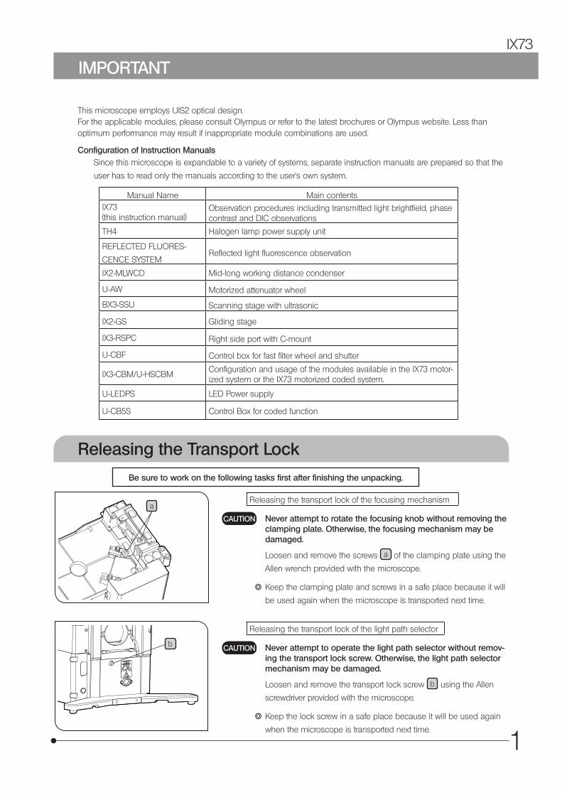
Be sure to work on the following tasks first after finishing the unpacking.
Releasing the Transport Lock
b
aReleasing the transport lock of the focusing mechanism
Never attempt to rotate the focusing knob without removing the clamping plate. Otherwise, the focusing mechanism may be damaged.
Loosen and remove the screws a of the clamping plate using the
Allen wrench provided with the microscope.
} Keep the clamping plate and screws in a safe place because it will
be used again when the microscope is transported next time.
Releasing the transport lock of the light path selector
Never attempt to operate the light path selector without remov-ing the transport lock screw. Otherwise, the light path selector mechanism may be damaged.
Loosen and remove the transport lock screw b using the Allen
screwdriver provided with the microscope.
} Keep the lock screw in a safe place because it will be used again
when the microscope is transported next time.
CAUTION
CAUTION
2
SAFETY PRECAUTIONS
b
a
1. If potentially infectious samples may be observed, use protective gloves or other protective means to prevent the skin from contacting with samples directly. After observation, be sure to clean the portion contacted with samples.
• Moving this device is accompanied with the risk of dropping the samples. Be sure to remove the samples before moving this device.
• In case the samples are damaged by erroneous operation, promptly take the infection prevention measures.
• Follow the procedures described in "Handling Precautions" (see page 6) prior to using the accessories of this device. Otherwise, the stability of the device will be lost and the dropped samples will cause the possibility of infection.
• When you maintain the device which may have contacted with potentially infectious samples, be sure to wear protectors such as gloves, or clean the device prior to operation.
• Before disposing of the device contacted with potentially infec-tious samples, be sure to follow the regulations and rules of your local government.
2. Be careful not to have your hand caught between the bottom of the revolving nosepiece and the microscope frame.
3. The microscope is not provided with a waterproof mechanism. Therefore, if culture liquid or water is spilt on the stage, revolving nosepiece or microscope frame, damage to the equipment or an electrical shock may result. Immediately wipe the liquid or water off if it is spilt on them.
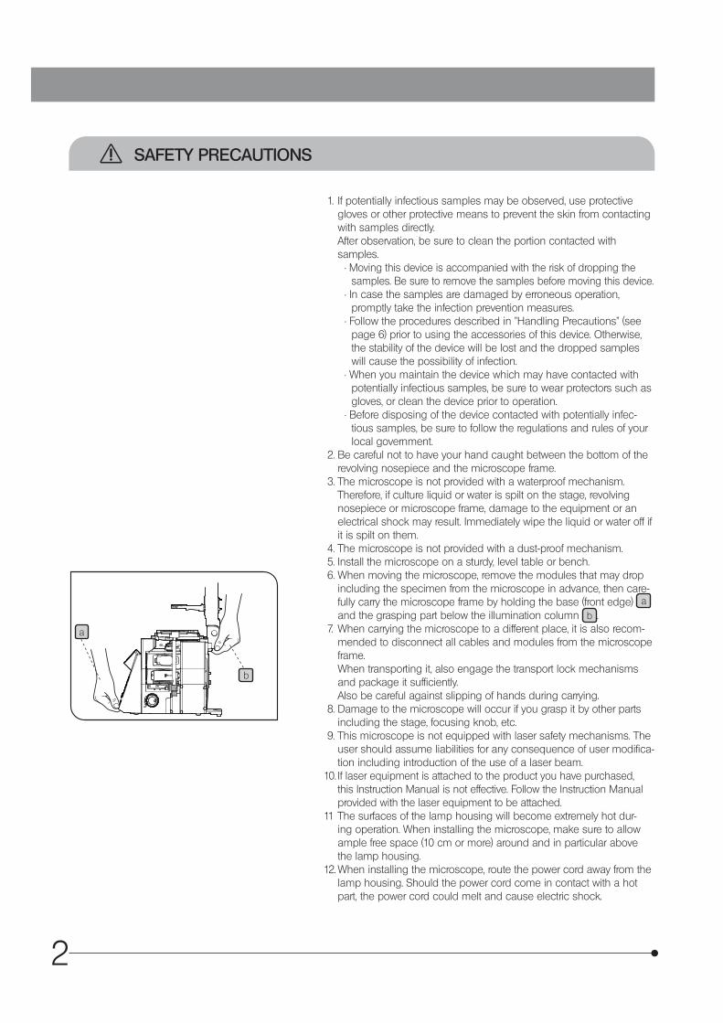
4. The microscope is not provided with a dust-proof mechanism.5. Install the microscope on a sturdy, level table or bench.6. When moving the microscope, remove the modules that may drop
including the specimen from the microscope in advance, then care-fully carry the microscope frame by holding the base (front edge) a and the grasping part below the illumination column b .
7. When carrying the microscope to a different place, it is also recom-mended to disconnect all cables and modules from the microscope frame. When transporting it, also engage the transport lock mechanisms and package it sufficiently. Also be careful against slipping of hands during carrying.
8. Damage to the microscope will occur if you grasp it by other parts including the stage, focusing knob, etc.
9. This microscope is not equipped with laser safety mechanisms. The user should assume liabilities for any consequence of user modifica-tion including introduction of the use of a laser beam.
10. If laser equipment is attached to the product you have purchased, this Instruction Manual is not effective. Follow the Instruction Manual provided with the laser equipment to be attached.
11 The surfaces of the lamp housing will become extremely hot dur-ing operation. When installing the microscope, make sure to allow ample free space (10 cm or more) around and in particular above the lamp housing.
12. When installing the microscope, route the power cord away from the lamp housing. Should the power cord come in contact with a hot part, the power cord could melt and cause electric shock.
3
IX73
c
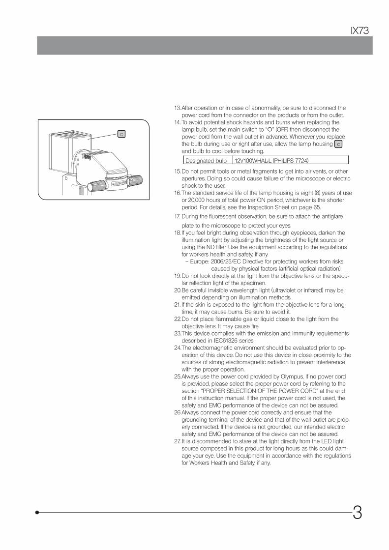
13. After operation or in case of abnormality, be sure to disconnect the power cord from the connector on the products or from the outlet.
14. To avoid potential shock hazards and burns when replacing the lamp bulb, set the main switch to “\” (OFF) then disconnect the power cord from the wall outlet in advance. Whenever you replace the bulb during use or right after use, allow the lamp housing c and bulb to cool before touching.
Designated bulb 12V100WHAL-L (PHILIPS 7724)
15. Do not permit tools or metal fragments to get into air vents, or other apertures. Doing so could cause failure of the microscope or electric shock to the user.
16. The standard service life of the lamp housing is eight (8) years of use or 20,000 hours of total power ON period, whichever is the shorter period. For details, see the Inspection Sheet on page 65.
17. During the fluorescent observation, be sure to attach the antiglare
plate to the microscope to protect your eyes.18. If you feel bright during observation through eyepieces, darken the
illumination light by adjusting the brightness of the light source or using the ND filter. Use the equipment according to the regulations for workers health and safety, if any.
– Europe: 2006/25/EC Directive for protecting workers from risks caused by physical factors (artificial optical radiation).
19. Do not look directly at the light from the objective lens or the specu-lar reflection light of the specimen.
20. Be careful invisible wavelength light (ultraviolet or infrared) may be emitted depending on illumination methods.
21. If the skin is exposed to the light from the objective lens for a long time, it may cause burns. Be sure to avoid it.
22. Do not place flammable gas or liquid close to the light from the objective lens. It may cause fire.
23. This device complies with the emission and immunity requirements described in IEC61326 series.
24. The electromagnetic environment should be evaluated prior to op-eration of this device. Do not use this device in close proximity to the sources of strong electromagnetic radiation to prevent interference with the proper operation.
25. Always use the power cord provided by Olympus. If no power cord is provided, please select the proper power cord by referring to the section “PROPER SELECTION OF THE POWER CORD” at the end of this instruction manual. If the proper power cord is not used, the safety and EMC performance of the device can not be assured.
26 Always connect the power cord correctly and ensure that the grounding terminal of the device and that of the wall outlet are prop-erly connected. If the device is not grounded, our intended electric safety and EMC performance of the device can not be assured.
27. It is discommended to stare at the light directly from the LED light source composed in this product for long hours as this could dam-age your eye. Use the equipment in accordance with the regulations for Workers Health and Safety, if any.
4
This device has been designed to be used to observe magnified images of specimens in various routine work andresearch applications.Do not use this device for any purpose other than its intended use.
This product complies with the requirements of directive 98/79/EC concerning in vitro diagnos-
tic medical devices. CE marking means the conformity to the directive.
EN61326-1 defines two categories according to the location for use.Class A : Equipment suitable for use in establishments other than domestic, and those directly connected to a low volt-
age power supply network which supplies buildings used for domestic purposes.Class B : Equipment for use in domestic establishments, and in establishments directly connected to a low voltage
power supply network which supplies buildings used for domestic purposes.This product is applied Class A. Some interference may occur if this system is used in domestic location.
USA: CAUTION:Federal law restricts this device to sale by or on the order of an appropriately licensed healthcare practitioner.
Caution labels
Caution labels are placed at parts where special precaution is required when handling and using the microscope.
Always pay attentions to the caution labels.
Positions of caution labelsLamp housing
Back side of microscope frame
If the caution label becomes dirty or is peeled off, contact Olympus for replacement.
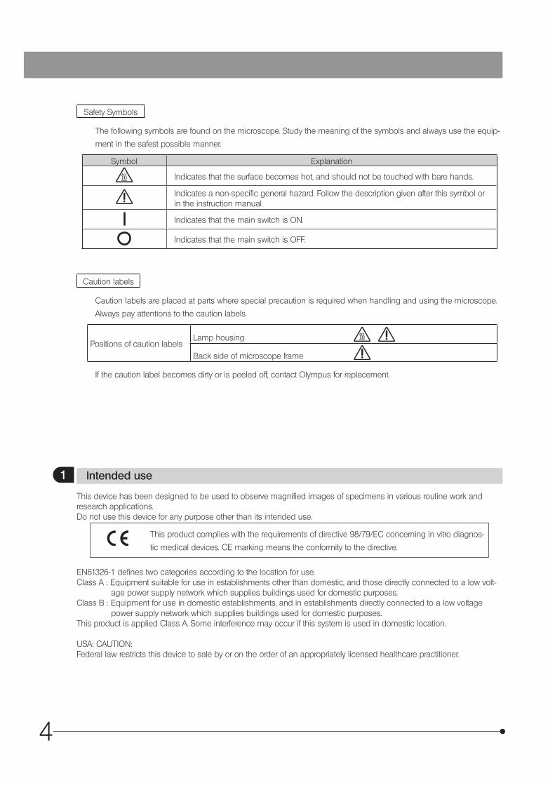
Safety Symbols
The following symbols are found on the microscope. Study the meaning of the symbols and always use the equip-
ment in the safest possible manner.
Symbol Explanation
Indicates that the surface becomes hot, and should not be touched with bare hands.
Indicates a non-specific general hazard. Follow the description given after this symbol or in the instruction manual.
Indicates that the main switch is ON.
Indicates that the main switch is OFF.
1 Intended use
5
IX73
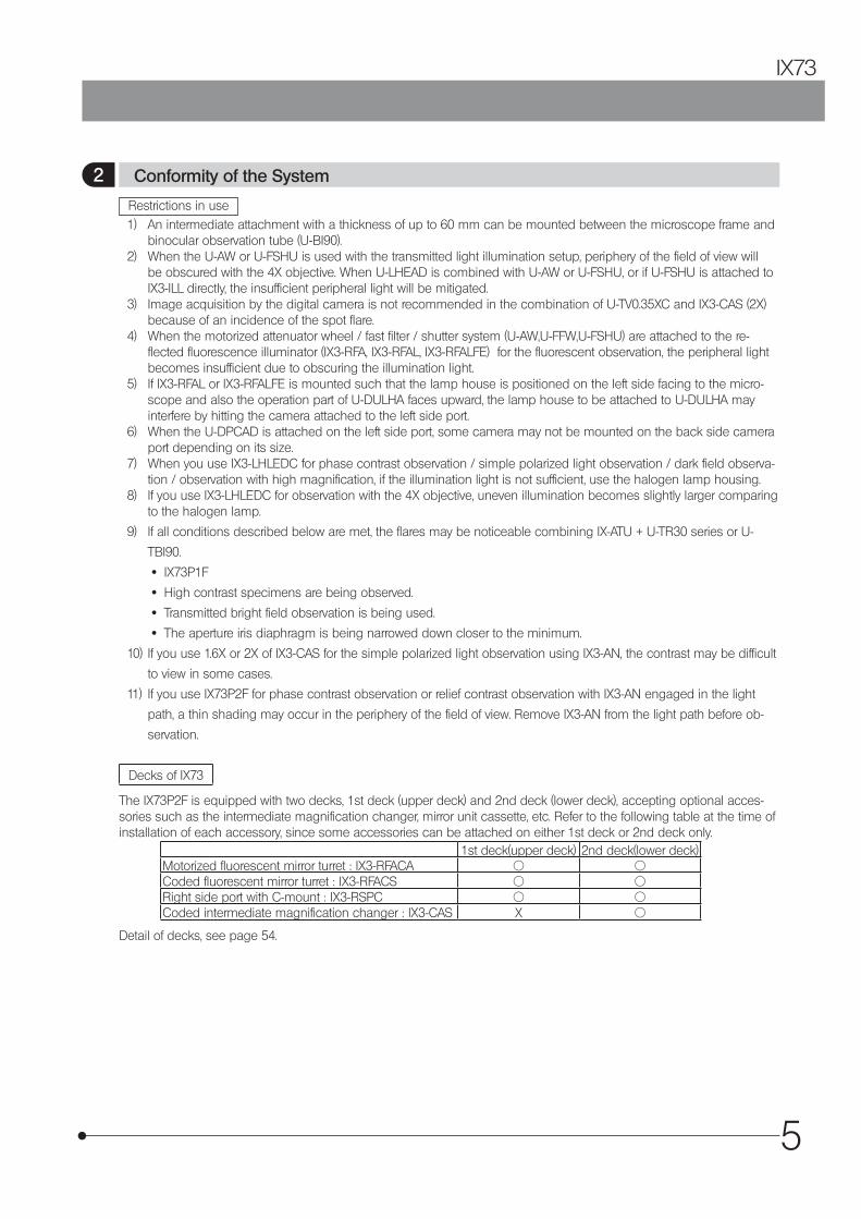
Restrictions in use1) An intermediate attachment with a thickness of up to 60 mm can be mounted between the microscope frame and
binocular observation tube (U-BI90). 2) When the U-AW or U-FSHU is used with the transmitted light illumination setup, periphery of the field of view will
be obscured with the 4X objective. When U-LHEAD is combined with U-AW or U-FSHU, or if U-FSHU is attached to IX3-ILL directly, the insufficient peripheral light will be mitigated.
3) Image acquisition by the digital camera is not recommended in the combination of U-TV0.35XC and IX3-CAS (2X) because of an incidence of the spot flare.
4) When the motorized attenuator wheel / fast filter / shutter system (U-AW,U-FFW,U-FSHU) are attached to the re-flected fluorescence illuminator (IX3-RFA, IX3-RFAL, IX3-RFALFE) for the fluorescent observation, the peripheral light becomes insufficient due to obscuring the illumination light.
5) If IX3-RFAL or IX3-RFALFE is mounted such that the lamp house is positioned on the left side facing to the micro-scope and also the operation part of U-DULHA faces upward, the lamp house to be attached to U-DULHA may interfere by hitting the camera attached to the left side port.
6) When the U-DPCAD is attached on the left side port, some camera may not be mounted on the back side camera port depending on its size.
7) When you use IX3-LHLEDC for phase contrast observation / simple polarized light observation / dark field observa-tion / observation with high magnification, if the illumination light is not sufficient, use the halogen lamp housing.
8) If you use IX3-LHLEDC for observation with the 4X objective, uneven illumination becomes slightly larger comparing to the halogen lamp.
9) If all conditions described below are met, the flares may be noticeable combining IX-ATU + U-TR30 series or U-
TBI90.
· IX73P1F
· High contrast specimens are being observed.
· Transmitted bright field observation is being used.
· The aperture iris diaphragm is being narrowed down closer to the minimum.
10) If you use 1.6X or 2X of IX3-CAS for the simple polarized light observation using IX3-AN, the contrast may be difficult
to view in some cases.
11) If you use IX73P2F for phase contrast observation or relief contrast observation with IX3-AN engaged in the light
path, a thin shading may occur in the periphery of the field of view. Remove IX3-AN from the light path before ob-
servation.
Decks of IX73
The IX73P2F is equipped with two decks, 1st deck (upper deck) and 2nd deck (lower deck), accepting optional acces-sories such as the intermediate magnification changer, mirror unit cassette, etc. Refer to the following table at the time of installation of each accessory, since some accessories can be attached on either 1st deck or 2nd deck only.
1st deck(upper deck) 2nd deck(lower deck)Motorized fluorescent mirror turret : IX3-RFACA = =Coded fluorescent mirror turret : IX3-RFACS = =Right side port with C-mount : IX3-RSPC = =Coded intermediate magnification changer : IX3-CAS X =
Detail of decks, see page 54.
2 Conformity of the System
6
1. These products are precision instruments. Handle them with care and avoid subjecting them to sudden or severe impact and also connect the cables gently.
2. Do not use the microscope where it is subjected to direct sunlight, high temperature and humidity, dust or vibrations. (For operating conditions, see Chapter 8, “SPECIFICATIONS” on page 49.)
3. When attaching or detaching any accessory, make sure to proceed in a condition that nothing is attached on the left side port.
4. To prevent malfunction, do not replace modules or connect/disconnect cables while the main switch of the IX3-
CBM is set to “ I ” ON.
5. Do not disassemble any part of the microscope. Doing so could cause failure of the microscope.6. Before disposing of this product, be sure to follow the regulations and rules of your local government.
1. Do not leave stains or fingerprints on the lenses and filters. Blow away dust with a commercially available blower and gently wipe the lens or filter with a piece of cleaning paper (or clean gauze). For wiping fingerprints and oil stains, use a piece of cleaning paper moistened with commercially available absolute alcohol.
Since the absolute alcohol is highly flammable, it must be handled carefully. Be sure to keep it away from open flames or potential sources of electrical sparks --- for example, electrical equipment that is being switched on or off, which could cause ignition of a fire. Also remember to always use absolute alcohol only in a well-ventilated room.
2. Do not use organic solvents, which cause painted and plastic parts to deteriorate. Do not use organic solvents to clean device components other than the glass components. To clean them, use a lint-free, soft cloth slightly moist-ened with a diluted neutral detergent.
3. This microscope is not provided with a dust-proof mechanism. When not using the microscope, make sure to set the main switch to “\” (OFF), confirm that the lamp housing is cool enough and cover the microscope with the provided dust cover.
CAUTION
3 Handling Precautions
4 Maintenance and Storage
7
IX73
OM1
PO/OM3PH/OM4
DIC/OM2
BF/OM5FL/OM6
ATTENUATOR / DIC
IX3
· IX73P1F· IX73P2F
Hand switchU-HSCBM*#
U-CB5S* #
Control box for coded function
· IX3-RFA*· IX3-RFALFE*· IX3-RFAL*
IX3-RSPC*
100 W halogen lamp house· U-LH100L-3· U-LH100-3+U-RMT
IX3-ILL
Halogen lamp power supply unit
TH4*
· IX3-RFACA*#
IX3-CBM* #
Control box M
· IX3-RFACS*#
IX3-CAS #
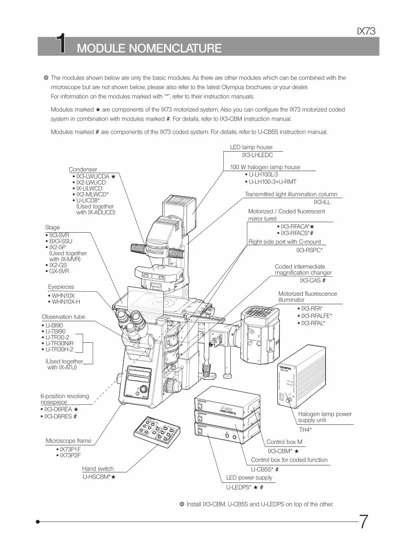
} The modules shown below are only the basic modules. As there are other modules which can be combined with the
microscope but are not shown below, please also refer to the latest Olympus brochures or your dealer.
For information on the modules marked with “*", refer to their instruction manuals.
Modules marked # are components of the IX73 motorized system. Also you can configure the IX73 motorized coded
system in combination with modules marked #. For details, refer to IX3-CBM instruction manual.
Modules marked # are components of the IX73 coded system. For details, refer to U-CB5S instruction manual.
· IX3-LWUCDA #· IX2-LWUCD· IX-ULWCD· IX2-MLWCD*· U-UCD8*
(Used together with IX-ADUCD)
Condenser
· IX3-SVR· BX3-SSU· IX2-SP
(Used together with IX-MVR)
· IX2-GS· GX-SVR
Stage
Eyepieces
· WHN10X· WHN10X-H
Observation tube· U-BI90· U-TBI90· U-TR30-2· U-TR30NIR· U-TR30H-2
(Used together with IX-ATU)
Microscope frame
6-position revolving nosepiece· IX3-D6REA #· IX3-D6RES #
Motorized fluorescence illuminator
Coded intermediate magnification changer
Right side port with C-mount
Motorized / Coded fluorescent mirror turret
Transmitted light illumination column
1 MODULE NOMENCLATURE
} Install IX3-CBM, U-CB5S and U-LEDPS on top of the other.
U-LEDPS* # #
LED power supply
LED lamp houseIX3-LHLEDC
8
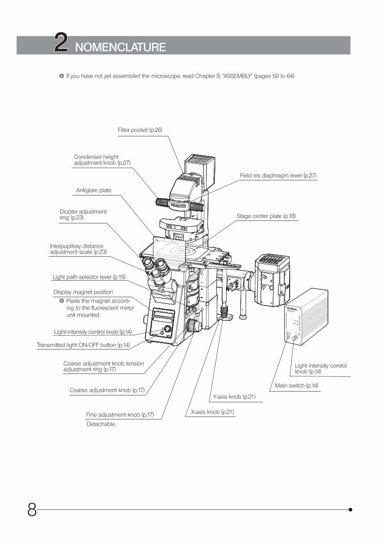
Stage center plate (p.18)
Detachable.
Main switch (p.14)
} If you have not yet assembled the microscope, read Chapter 9, “ASSEMBLY” (pages 50 to 64).
Filter pocket (p.26)
Condenser height adjustment knob (p.27)
Diopter adjustment ring (p.23)
Interpupillary distance adjustment scale (p.23)
Coarse adjustment knob tension adjustment ring (p.17)
Coarse adjustment knob (p.17)
Fine adjustment knob (p.17) X-axis knob (p.21)
Y-axis knob (p.21)
Light intensity control knob (p.14)
Field iris diaphragm lever (p.27)
2 NOMENCLATURE
Antiglare plate
Light intensity control knob (p.14)
Light path selector lever (p.15)
Transmitted light ON-OFF button (p.14)
Display magnet position
} Paste the magnet accord-ing to the fluorescent mirror unit mounted.
9
IX73
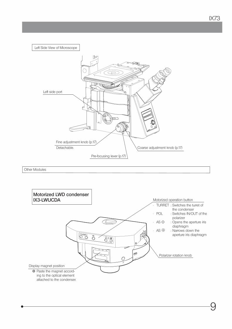
Left Side View of Microscope
Other Modules
Left side port
Pre-focusing lever (p.17)
Detachable. Coarse adjustment knob (p.17)
Fine adjustment knob (p.17)
Motorized LWD condenserIX3-LWUCDA Motorized operation button
• TURRET : Switches the turret of the condenser
• POL : Switches IN/OUT of the polarizer
• AS \ : Opens the aperture iris diaphragm
• AS : Narrows down the aperture iris diaphragm
Display magnet position
} Paste the magnet accord-ing to the optical element attached to the condenser.
Polarizer rotation knob
10
OM1
PO/OM3PH/OM4
DIC/OM2
BF/OM5FL/OM6
ATTENUATOR / DIC
IX3
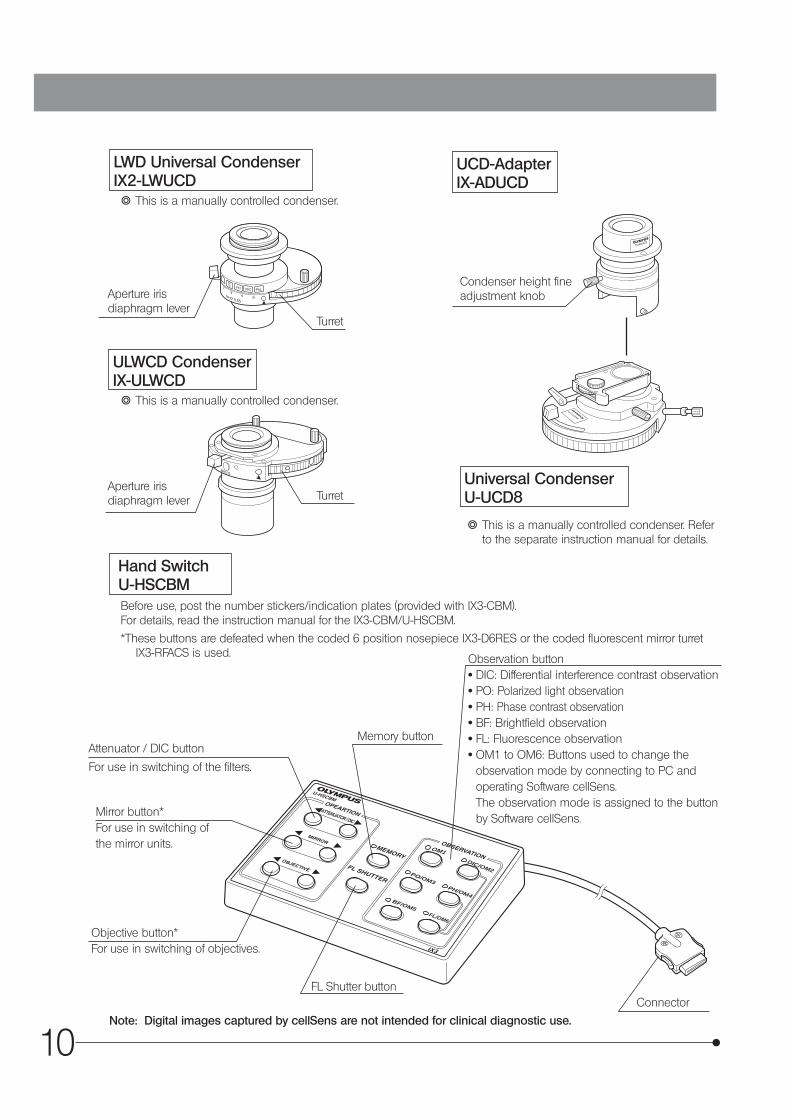
Before use, post the number stickers/indication plates (provided with IX3-CBM).For details, read the instruction manual for the IX3-CBM/U-HSCBM.
*These buttons are defeated when the coded 6 position nosepiece IX3-D6RES or the coded fluorescent mirror turret IX3-RFACS is used.
Attenuator / DIC button
For use in switching of the filters.
Mirror button*For use in switching of the mirror units.
Objective button*For use in switching of objectives.
Memory button
FL Shutter button
Observation button· DIC: Differential interference contrast observation· PO: Polarized light observation· PH: Phase contrast observation· BF: Brightfield observation· FL: Fluorescence observation· OM1 to OM6: Buttons used to change the
observation mode by connecting to PC and operating Software cellSens. The observation mode is assigned to the button by Software cellSens.
Connector
LWD Universal Condenser IX2-LWUCD
UCD-Adapter IX-ADUCD
ULWCD CondenserIX-ULWCD
} This is a manually controlled condenser.
} This is a manually controlled condenser.
} This is a manually controlled condenser. Refer to the separate instruction manual for details.
Turret
Turret
Condenser height fine adjustment knobAperture iris
diaphragm lever
Aperture iris diaphragm lever
Universal Condenser U-UCD8
Hand Switch U-HSCBM
Note: Digital images captured by cellSens are not intended for clinical diagnostic use.
11
IX73
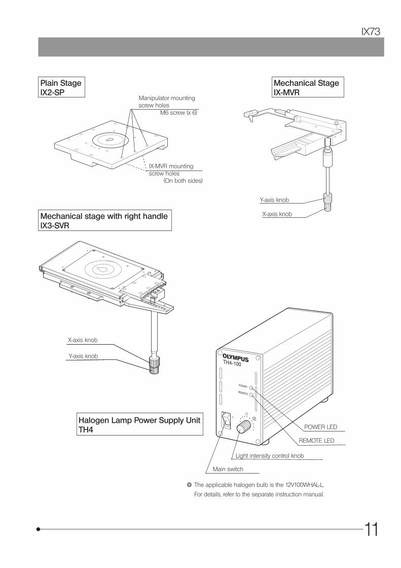
Light intensity control knob
Main switch
POWER LED
REMOTE LED
} The applicable halogen bulb is the 12V100WHAL-L.
For details, refer to the separate instruction manual.
Manipulator mounting screw holes
M6 screw (x 6)
IX-MVR mounting screw holes
(On both sides)
Plain Stage IX2-SP
Mechanical StageIX-MVR
X-axis knob
Y-axis knob
Y-axis knob
X-axis knobMechanical stage with right handleIX3-SVR
Halogen Lamp Power Supply UnitTH4
12
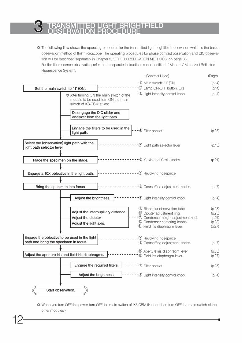
} The following flow shows the operating procedure for the transmitted light brightfield observation which is the basic
observation method of this microscope. The operating procedures for phase contrast observation and DIC observa-
tion will be described separately in Chapter 5, “OTHER OBSERVATION METHODS” on page 33.
For the fluorescence observation, refer to the separate instruction manual entitled “ Manual / Motorized Reflected
Fluorescence System”.
Set the main switch to “ I” (ON).
Place the specimen on the stage.
Engage a 10X objective in the light path.
Bring the specimen into focus.
Engage the objective to be used in the light path and bring the specimen in focus.
Adjust the aperture iris and field iris diaphragms.
Disengage the DIC slider and analyzer from the light path.
Engage the filters to be used in the light path.
Adjust the interpupillary distance.
Adjust the diopter.
Adjust the light axis.
Adjust the brightness.
Start observation.
(Controls Used) (Page)
2 Lamp ON-OFF button: ON (p.14)
4 Filter pocket (p.26)
7 Filter pocket (p.26)
@ Main switch: “ I” (ON) (p.14)
3 Light intensity control knob (p.14)
Select the (observation) light path with the light path selector lever. 5 Light path selector lever (p.15)
6 X-axis and Y-axis knobs (p.21)
7 Revolving nosepiece
8 Coarse/fine adjustment knobs (p.17)
Adjust the brightness. 3 Light intensity control knob (p.14)
3 Light intensity control knob (p.14)
d Field iris diaphragm lever (p.27)c Condenser centering knobs (p.28)b Condenser height adjustment knob (p.27)a Diopter adjustment ring (p.23)9 Binocular observation tube (p.23)
7 Revolving nosepiece8 Coarse/fine adjustment knobs (p.17)
e Aperture iris diaphragm lever (p.30)d Field iris diaphragm lever (p.27)
Engage the required filters.
3 TRANSMITTED LIGHT BRIGHTFIELD OBSERVATION PROCEDURE
} After turning ON the main switch of the module to be used, turn ON the main switch of IX3-CBM at last.
} When you turn OFF the power, turn OFF the main switch of IX3-CBM first and then turn OFF the main switch of the
other modules.7
13
IX73
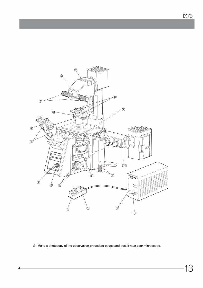
} Make a photocopy of the observation procedure pages and post it near your microscope.
a
d
e
123
4
5
7
8
bc
3
23
6
9
14
4-1 Power Supply Unit and Microscope Frame
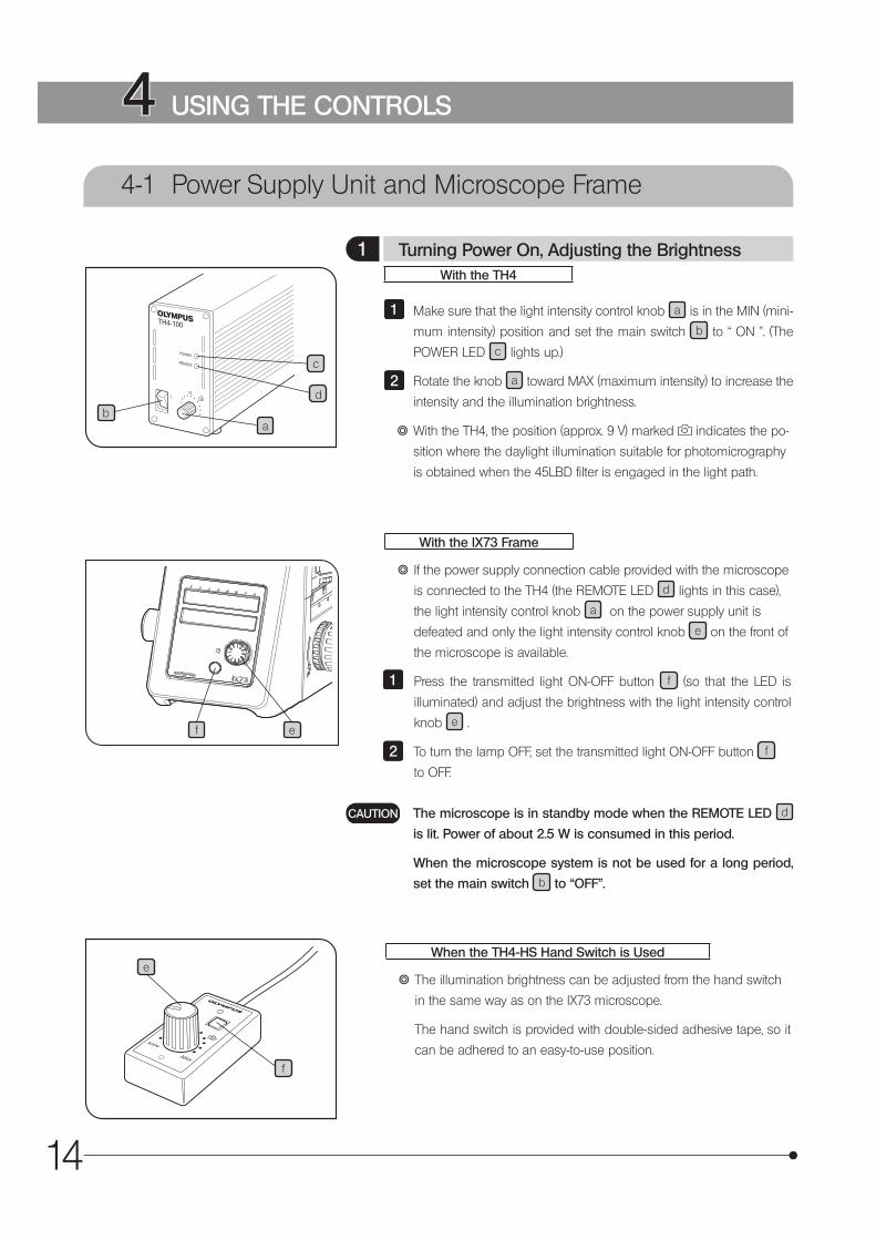
With the TH4
Make sure that the light intensity control knob a is in the MIN (mini-
mum intensity) position and set the main switch b to “ ON ”. (The
POWER LED c lights up.)
Rotate the knob a toward MAX (maximum intensity) to increase the
intensity and the illumination brightness.
} With the TH4, the position (approx. 9 V) marked indicates the po-
sition where the daylight illumination suitable for photomicrography
is obtained when the 45LBD filter is engaged in the light path.
1
2
With the IX73 Frame
} If the power supply connection cable provided with the microscope
is connected to the TH4 (the REMOTE LED d lights in this case),
the light intensity control knob a on the power supply unit is
defeated and only the light intensity control knob e on the front of
the microscope is available.
Press the transmitted light ON-OFF button f (so that the LED is
illuminated) and adjust the brightness with the light intensity control
knob e .
To turn the lamp OFF, set the transmitted light ON-OFF button f
to OFF.
1
2
The microscope is in standby mode when the REMOTE LED d
is lit. Power of about 2.5 W is consumed in this period.
When the microscope system is not be used for a long period,
set the main switch b to “OFF”.
CAUTION
When the TH4-HS Hand Switch is Used
} The illumination brightness can be adjusted from the hand switch
in the same way as on the IX73 microscope.
The hand switch is provided with double-sided adhesive tape, so it
can be adhered to an easy-to-use position.
4 USING THE CONTROLS
1 Turning Power On, Adjusting the Brightness
ba
c
d
ef
e
f

15
IX73
} The light path selector lever a allows for light path switching
between the observation and left side port paths.
Eyepiece / Camera (Left side port)100% / 0%
50% / 50%
0% / 100%
} If acquiring the image by setting the light path as [Eyepiece 50%/
Left side port 50%], the light such as fluorescent lamp may enter
from the eyepiece to be reflected in the acquired image.
} Attaching the M4 screw provided with the microscope to either one
of screw holes b allows switching the light path in 2 levels.
Use the coded intermediate magnification changer IX3-CAS to
switch the observation magnification in the following 3 levels ac-
cording to the objective lens magnification.
· 1X
· 1.6X
· 2X
For the assembly procedure, refer to page 54 .
Change the magnification by operating the changing slider.1
2 Light Path Selection
3 Coded intermediate magnification changer IX3-CAS
} This is the module for clamping the microscope onto an antivibra-
tion platform. The applicable anti-vibration platforms are the follow-
ing four models.
· 25 mm pitch and 50 mm pitch anti-vibration platforms.
· 1-inch pitch and 2-inch pitch anti-vibration platforms.
For the assembly procedure, refer to page 61
4 Frame Fix Plate IX3-FP
b a
1

16
} This tray prevents dust, etc. from falling into the microscope.
Remove and clean it on a regular basis.
Rotate the fixing screws (2 pcs.) to remove them.
Slide the dust tray to remove it.
} Wash the dust tray with water and wipe it with the dry cloth to dry
well before attaching it to the microscope.
1
2
5 Dust tray

17
IX73
4-2 Focusing Block
} The fine adjustment knob is designed detachable in order to prevent interference between the knob and the operator’s hand manipulating the X- and Y-axis knobs.
· Loosen the clamping screw c using the Allen screwdriver provided
with the microscope and remove the fine adjustment knob. · After detaching, the fine adjustment knob is hollowed to facilitate
manipulation with a fingertip.
} Rotating the coarse or fine focus adjustment knob a toward the front (in the direction of the arrow) raises the objective and toward the rear (opposite direction) lowers the objective.
} The pre-focusing lever prevents collision between the specimen
and objective and simplifies the focusing operation.
After bringing the specimen into approximate focus with the coarse
adjustment knob, turn the pre-focusing lever d in the direction of the
arrow to lock it. Hereafter, the upper limit of the coarse adjustment will
be limited at the position where the lever is locked.
When bringing a specimen in focus, approximate focus can be ob-
tained by simply raising the coarse adjustment to the stop position
so all you have to do additionally is control the fine adjustment knob.
} The focusing function using the fine adjustment knob is not limited.
} Always use the rotation tension adjustment ring b to control the
rotation tension of the coarse adjustment knob.
The tension of the coarse adjustment knob has been pre-adjusted
to optimum tension, but this can be changed as required. Turn the
rotation tension adjustment ring b in the direction of the arrow to
decrease the knob’s tension and in the opposite direction to increase it.
4 Pre-focusing Lever
3 Detaching the Fine Adjustment Knob
2 Adjusting the Coarse Adjustment Knob Tension
1 Rotation Direction of the Coarse/Fine Adjustment Knobs
ca
b
d
18
4-3 Stage
a
b
c
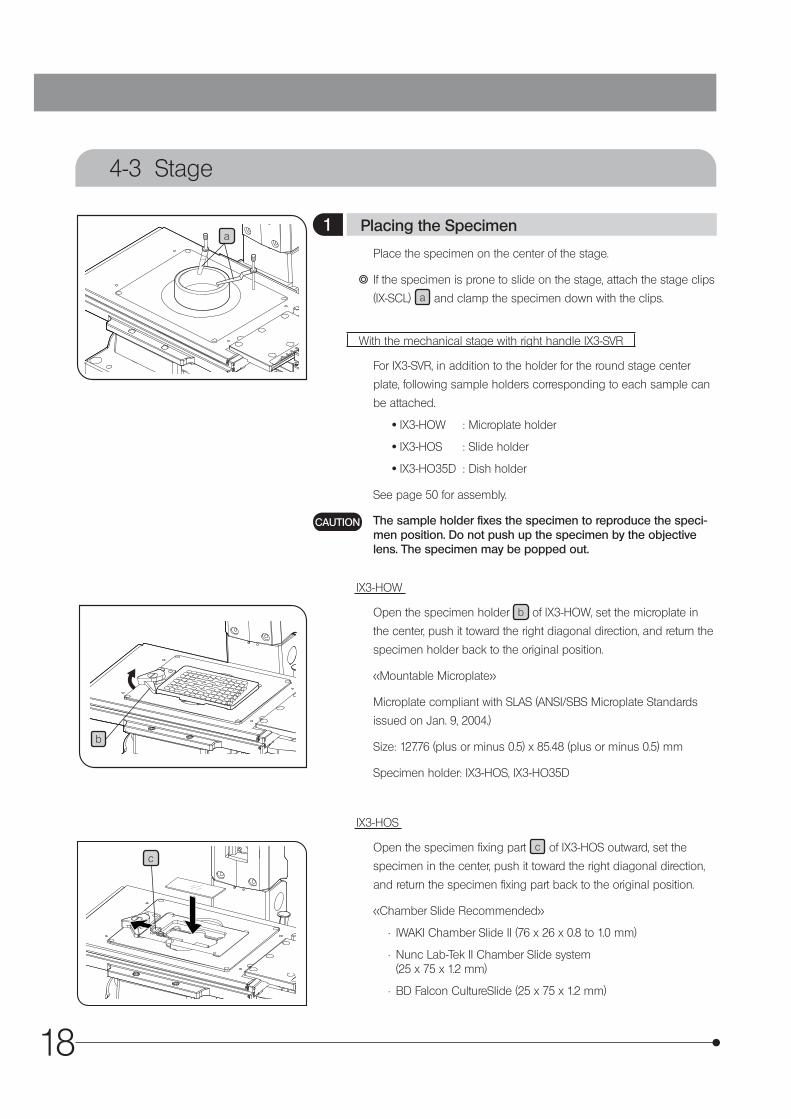
Place the specimen on the center of the stage.
} If the specimen is prone to slide on the stage, attach the stage clips
(IX-SCL) a and clamp the specimen down with the clips.
With the mechanical stage with right handle IX3-SVR
For IX3-SVR, in addition to the holder for the round stage center
plate, following sample holders corresponding to each sample can
be attached.
· IX3-HOW : Microplate holder
· IX3-HOS : Slide holder
· IX3-HO35D : Dish holder
See page 50 for assembly.
The sample holder fixes the specimen to reproduce the speci-men position. Do not push up the specimen by the objective lens. The specimen may be popped out.
IX3-HOW
Open the specimen holder b of IX3-HOW, set the microplate in
the center, push it toward the right diagonal direction, and return the
specimen holder back to the original position.
<<Mountable Microplate>>
Microplate compliant with SLAS (ANSI/SBS Microplate Standards
issued on Jan. 9, 2004.)
Size: 127.76 (plus or minus 0.5) x 85.48 (plus or minus 0.5) mm
Specimen holder: IX3-HOS, IX3-HO35D
IX3-HOS
Open the specimen fixing part c of IX3-HOS outward, set the
specimen in the center, push it toward the right diagonal direction,
and return the specimen fixing part back to the original position.
<<Chamber Slide Recommended>>
• IWAKI Chamber Slide II (76 x 26 x 0.8 to 1.0 mm)
• Nunc Lab-Tek II Chamber Slide system (25 x 75 x 1.2 mm)
• BD Falcon CultureSlide (25 x 75 x 1.2 mm)
CAUTION
1 Placing the Specimen

19
IX73
f
4
i
d
h
e
i
g
e
IX3-HO35D
Place the 35 mm dish d on the 35 mm dish fixing holder e .
Tighten the fixing screws f (3 screws) placed on the side with the
Allen screwdriver provided with IX3-HO35D to secure the 35 mm
dish.
} The 35 mm dish can be secured easily by tightening the fixing
screws after flipping over the 35 mm dish in advance.
Do not tighten the fixing screws too firmly. The dish may be damaged.
Set the fixing holder e in the center of IX3-HO35D g so that the
cut-out meets the holder fixing knob i .
Loosen the holder fixing knobs i .
Rotate the fixing holder e clockwise to push it to the rotation stop-
per h .
Tighten the holder fixing knobs i .
} The 35 mm dish fixing holder e can be sterilized by using the
autoclave.
<<35 mm Glass Bottom Dish Recommended>>
• Matsunami Glass D111310
• MatTek P35GC-1.5-14-C
<<35 mm Dish Recommended>>
• BD Falcon 351008
1
CAUTION
2
3
4
5
20
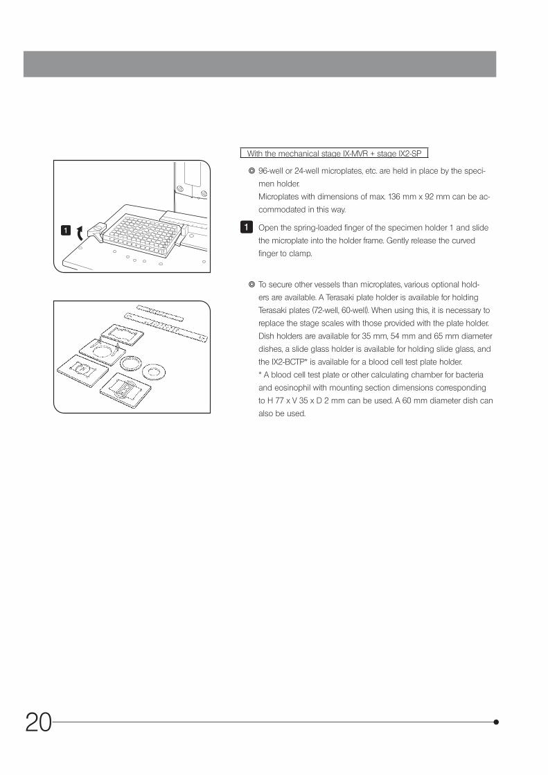
With the mechanical stage IX-MVR + stage IX2-SP
} 96-well or 24-well microplates, etc. are held in place by the speci-
men holder.
Microplates with dimensions of max. 136 mm x 92 mm can be ac-
commodated in this way.
Open the spring-loaded finger of the specimen holder 1 and slide
the microplate into the holder frame. Gently release the curved
finger to clamp.
} To secure other vessels than microplates, various optional hold-
ers are available. A Terasaki plate holder is available for holding
Terasaki plates (72-well, 60-well). When using this, it is necessary to
replace the stage scales with those provided with the plate holder.
Dish holders are available for 35 mm, 54 mm and 65 mm diameter
dishes, a slide glass holder is available for holding slide glass, and
the IX2-BCTP* is available for a blood cell test plate holder.
* A blood cell test plate or other calculating chamber for bacteria
and eosinophil with mounting section dimensions corresponding
to H 77 x V 35 x D 2 mm can be used. A 60 mm diameter dish can
also be used.
11
21
IX73
c
d
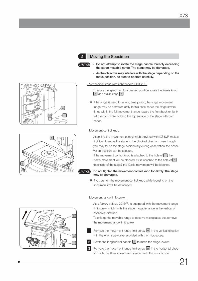
Movement range limit screw
As a factory default, IX3-SVR, is equipped with the movement range
limit screw which limits the stage movable range in the vertical or
horizontal direction.
To enlarge the movable range to observe microplates, etc., remove
the movement range limit screw.
Remove the movement range limit screw e in the vertical direction
with the Allen screwdriver provided with the microscope.
Rotate the longitudinal handle f to move the stage inward.
Remove the movement range limit screw g in the horizontal direc-
tion with the Allen screwdriver provided with the microscope.
1
2
3
e
g
f
b
a
• Do not attempt to rotate the stage handle forcedly exceeding the stage movable range. The stage may be damaged.
• As the objective may interfere with the stage depending on the focus position, be sure to operate carefully.
CAUTION
Mechanical stage with right handle (IX3-SVR)
To move the specimen to a desired position, rotate the X-axis knob a and Y-axis knob b .
} If the stage is used for a long time period, the stage movement
range may be narrower rarely. In this case, move the stage several
times within the full movement range toward the front/back or right/
left direction while holding the top surface of the stage with both
hands.
Movement control knob
Attaching the movement control knob provided with IX3-SVR makes
it difficult to move the stage in the blocked direction. Even though
you may touch the stage accidentally during observation, the obser-
vation position can be secured.
If the movement control knob is attached to the hole of c , the
Y-axis movement will be blocked. If it is attached to the hole of d
(backside of the stage), the X-axis movement will be blocked.
Do not tighten the movement control knob too firmly. The stage may be damaged.
} If you tighten the movement control knob while focusing on the
specimen, it will be defocused.
CAUTION
2 Moving the Specimen

22
Stage movable range
With movement range limit screw : 50 mm in vertical direction, 50
mm in horizontal direction
Without movement range limit screw: 75 mm in vertical direction,
114 mm in horizontal direction
When using the center plate provided with IX3-SVR, attach the movement range limit screw.
If the movement range limit screw is not attached, the objective may hit the stage.
With the Mechanical Stage IX-MVR
To move the specimen to a desired position, rotate the X-axis knob
and Y-axis knob in the same manner as IX3-SVR.
} The stage travel area is 130 mm (X-axis) x 85 mm (Y-axis).
CAUTION
With the Stage BX3-SSU or IX3-SVR
} A grounding wire can be attached to the stage for electrophysiologi-cal experiments, etc.
Prepare a grounding wire a and one M4 screw b and attach the grounding wire to a screw hole on the stage surface.
The screw hole may sometimes be stuck by paint, etc. In such a case, screw in the M4 screw a few times to expose the metal-lic thread inside the screw hole and improve the contact before attaching the grounding wire firmly.
CAUTION
a
b
3 Connecting the Grounding Wire
23
IX73
4-4 Observation Tube
a
b
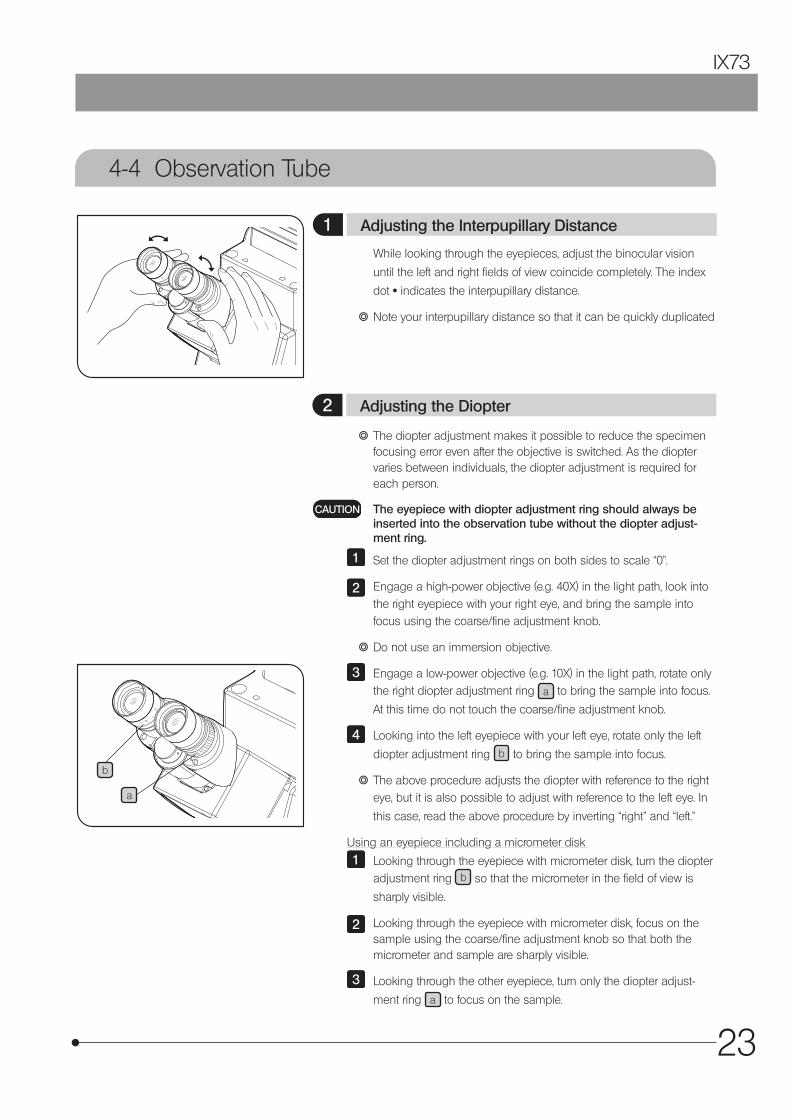
While looking through the eyepieces, adjust the binocular vision
until the left and right fields of view coincide completely. The index
dot · indicates the interpupillary distance.
} Note your interpupillary distance so that it can be quickly duplicated
} The diopter adjustment makes it possible to reduce the specimen focusing error even after the objective is switched. As the diopter varies between individuals, the diopter adjustment is required for each person.
The eyepiece with diopter adjustment ring should always be inserted into the observation tube without the diopter adjust-ment ring.
Set the diopter adjustment rings on both sides to scale “0”.
Engage a high-power objective (e.g. 40X) in the light path, look into the right eyepiece with your right eye, and bring the sample into focus using the coarse/fine adjustment knob.
} Do not use an immersion objective.
Engage a low-power objective (e.g. 10X) in the light path, rotate only the right diopter adjustment ring a to bring the sample into focus.
At this time do not touch the coarse/fine adjustment knob.
Looking into the left eyepiece with your left eye, rotate only the left
diopter adjustment ring b to bring the sample into focus.
} The above procedure adjusts the diopter with reference to the right eye, but it is also possible to adjust with reference to the left eye. In
this case, read the above procedure by inverting “right” and “left.”
Using an eyepiece including a micrometer disk
Looking through the eyepiece with micrometer disk, turn the diopter adjustment ring b so that the micrometer in the field of view is
sharply visible.
Looking through the eyepiece with micrometer disk, focus on the sample using the coarse/fine adjustment knob so that both the micrometer and sample are sharply visible.
Looking through the other eyepiece, turn only the diopter adjust-
ment ring a to focus on the sample.
CAUTION
1
2
3
4
1
2
3
1 Adjusting the Interpupillary Distance
2 Adjusting the Diopter
24
a
b
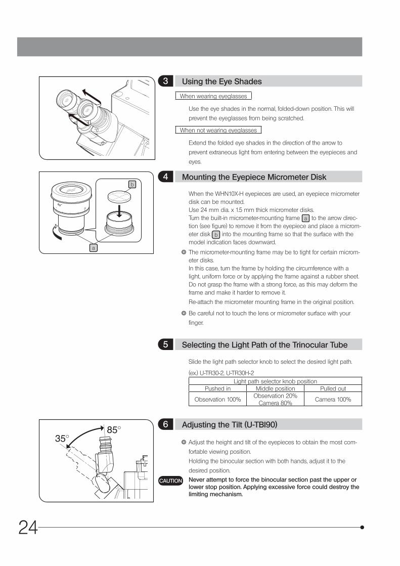
When wearing eyeglasses
Use the eye shades in the normal, folded-down position. This will
prevent the eyeglasses from being scratched.
When not wearing eyeglasses
Extend the folded eye shades in the direction of the arrow to
prevent extraneous light from entering between the eyepieces and
eyes.
When the WHN10X-H eyepieces are used, an eyepiece micrometer disk can be mounted. Use 24 mm dia. x 1.5 mm thick micrometer disks. Turn the built-in micrometer-mounting frame a to the arrow direc-tion (see figure) to remove it from the eyepiece and place a microm-eter disk b into the mounting frame so that the surface with the model indication faces downward.
} The micrometer-mounting frame may be to tight for certain microm-eter disks. In this case, turn the frame by holding the circumference with a light, uniform force or by applying the frame against a rubber sheet. Do not grasp the frame with a strong force, as this may deform the frame and make it harder to remove it.
Re-attach the micrometer mounting frame in the original position.
} Be careful not to touch the lens or micrometer surface with your
finger.
Slide the light path selector knob to select the desired light path.
(ex.) U-TR30-2, U-TR30H-2Light path selector knob position
Pushed in Middle position Pulled out
Observation 100%Observation 20%
Camera 80%Camera 100%
} Adjust the height and tilt of the eyepieces to obtain the most com-
fortable viewing position.
Holding the binocular section with both hands, adjust it to the
desired position.
Never attempt to force the binocular section past the upper or lower stop position. Applying excessive force could destroy the limiting mechanism.
CAUTION
3 Using the Eye Shades
4 Mounting the Eyepiece Micrometer Disk
5 Selecting the Light Path of the Trinocular Tube
6 Adjusting the Tilt (U-TBI90)
25
IX73
4-5 Illumination Column (IX3-ILL)
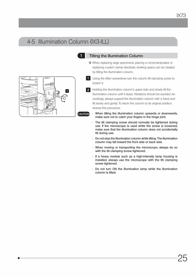
} When replacing large specimens, placing a micromanipulator or
replacing a patch clamp electrode, working space can be created
by tilting the illumination column.
Using the Allen screwdriver, turn the column tilt clamping screw to
loosen it.
Holding the illumination column’s upper side and slowly tilt the
illumination column until it stops. Vibrations should be avoided. Ac-
cordingly, always support the illumination column with a hand and
tilt slowly and gently. To return the column to its original position,
reverse this procedure.
• When tilting the illumination column upwards or downwards, make sure not to catch your fingers in the hinge joint.
• The tilt clamping screw should normally be tightened during use. If the microscope is used while the screw is loosened, make sure that the illumination column does not accidentally tilt during use.
• Do not stop the illumination column while tilting. The illumination column may fall toward the front side or back side.
• When moving or transporting the microscope, always do so with the tilt clamping screw tightened.
• If a heavy module such as a high-intensity lamp housing is installed, always use the microscope with the tilt clamping screw tightened.
• Do not turn ON the illumination lamp while the illumination column is tilted.
1
2
CAUTION
1 Tilting the Illumination Column
1

26
a
b
} 45 mm diameter, maximum 6 mm thick filters can be mounted. Vari-
ous filters, such as the frost filter Ø45 mm (45FR), color temperature
conversion filter (LBD), green interference filter (IF550) and ND filter
can be mounted.
Place a finger on the milled section a of the filter holder and lift it.
While holding the mounting lever b of the filter holder, insert a filter.
• Hold the filter by its edge to avoid leaving fingerprints or smudges on the filter surfaces.
• Shortly after the transmitted light illumination has been used, the filter will be very hot. Be sure to set the main switch to “\” (OFF) and allow the filter holder and filters to cool down before replacing filters.
Return the filter holder.
• If the uneven brightness of the illumination light bothers you, we recommend engaging frost filter Ø45 mm (45FR), sold separately, in the light path.
• If the filter holder is open, you may be dazzled by the light leaked from the light source in some cases. We recommend closing the filter holder before using the microscope
1
2
CAUTION
3
CAUTION
2 Mounting Filters1
2
3
27
IX73
Field irisdiaphragm
a
b
1
2 4
3
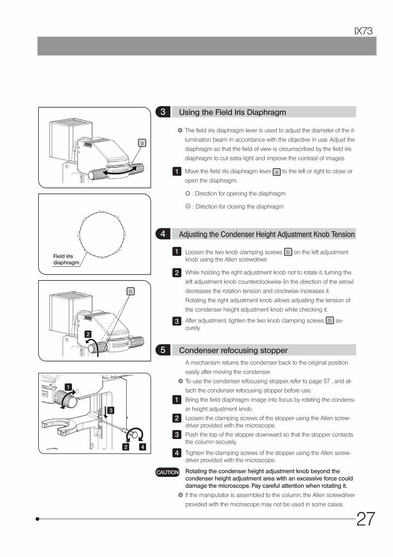
} The field iris diaphragm lever is used to adjust the diameter of the il-
lumination beam in accordance with the objective in use. Adjust the
diaphragm so that the field of view is circumscribed by the field iris
diaphragm to cut extra light and improve the contrast of images.
Move the field iris diaphragm lever a to the left or right to close or
open the diaphragm.
\ : Direction for opening the diaphragm
: Direction for closing the diaphragm
1
Loosen the two knob clamping screws b on the left adjustment knob using the Allen screwdriver.
While holding the right adjustment knob not to rotate it, turning the
left adjustment knob counterclockwise (in the direction of the arrow)
decreases the rotation tension and clockwise increases it.
Rotating the right adjustment knob allows adjusting the tension of
the condenser height adjustment knob while checking it.
After adjustment, tighten the two knob clamping screws b se-curely.
1
2
3
A mechanism returns the condenser back to the original position
easily after moving the condenser.
} To use the condenser refocusing stopper, refer to page 57 , and at-
tach the condenser refocusing stopper before use.
Bring the field diaphragm image into focus by rotating the condens-
er height adjustment knob.
Loosen the clamping screws of the stopper using the Allen screw-driver provided with the microscope.
Push the top of the stopper downward so that the stopper contacts the column securely.
Tighten the clamping screws of the stopper using the Allen screw-driver provided with the microscope.
Rotating the condenser height adjustment knob beyond the condenser height adjustment area with an excessive force could damage the microscope. Pay careful attention when rotating it.
} If the manipulator is assembled to the column, the Allen screwdriver
provided with the microscope may not be used in some cases.
1
2
3
4
CAUTION
3 Using the Field Iris Diaphragm
4 Adjusting the Condenser Height Adjustment Knob Tension
5 Condenser refocusing stopper
2
28
4-6 Condenser
1
2
a
57
6
8
3
7
8
b
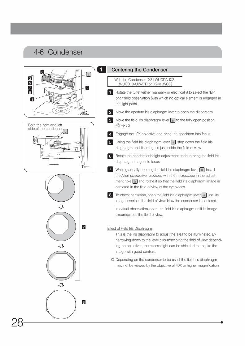
With the Condenser (IX3-LWUCDA, IX2-LWUCD, IX-ULWCD or IX2-MLWCD)
Rotate the turret (either manually or electrically) to select the “BF”
brightfield observation (with which no optical element is engaged in
the light path).
Move the aperture iris diaphragm lever to open the diaphragm.
Move the field iris diaphragm lever a to the fully open position
( ).
Engage the 10X objective and bring the specimen into focus.
Using the field iris diaphragm lever a , stop down the field iris
diaphragm until its image is just inside the field of view.
Rotate the condenser height adjustment knob to bring the field iris
diaphragm image into focus.
While gradually opening the field iris diaphragm lever a , install
the Allen screwdriver provided with the microscope in the adjust-
ment hole b and rotate it so that the field iris diaphragm image is
centered in the field of view of the eyepieces.
To check centration, open the field iris diaphragm lever a until its
image inscribes the field of view. Now the condenser is centered.
In actual observation, open the field iris diaphragm until its image
circumscribes the field of view.
Effect of Field Iris Diaphragm
This is the iris diaphragm to adjust the area to be illuminated. By
narrowing down to the level circumscribing the field of view depend-
ing on objectives, the excess light can be shielded to acquire the
image with good contrast.
} Depending on the condenser to be used, the field iris diaphragm
may not be viewed by the objective of 40X or higher magnification.
1
2
3
4
5
6
7
8
1 Centering the Condenser
Both the right and left side of the condenser
29
IX73
1
2
3
4
5
7
8
10
9
a
b
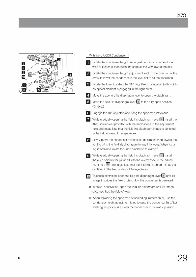
With the U-UCD8 Condenser
Rotate the condenser height fine adjustment knob counterclock-
wise to loosen it, then push the knob all the way toward the rear.
Rotate the condenser height adjustment knob in the direction of the
arrow to lower the condenser to the level not to hit the specimen.
Rotate the turret to select the “BF” brightfield observation (with which
no optical element is engaged in the light path).
Move the aperture iris diaphragm lever to open the diaphragm.
Move the field iris diaphragm lever a to the fully open position
( ).
Engage the 10X objective and bring the specimen into focus.
While gradually opening the field iris diaphragm lever a , install the
Allen screwdriver provided with the microscope in the adjustment
hole and rotate it so that the field iris diaphragm image is centered
in the field of view of the eyepieces.
Slowly move the condenser height fine adjustment knob toward the
front to bring the field iris diaphragm image into focus. When focus-
ing is obtained, rotate the knob clockwise to clamp it.
While gradually opening the field iris diaphragm lever a , install
the Allen screwdriver provided with the microscope in the adjust-
ment hole b and rotate it so that the field iris diaphragm image is
centered in the field of view of the eyepieces.
To check centration, open the field iris diaphragm lever a until its
image inscribes the field of view. Now the condenser is centered.
} In actual observation, open the field iris diaphragm until its image
circumscribes the field of view.
} When replacing the specimen or spreading immersion oil, use the
condenser height adjustment knob to raise the condenser first. After
finishing the procedure, lower the condenser to its lowest position.
1
2
3
4
5
6
7
8
9
10
30
70-80%
30-20%
Objective pupil
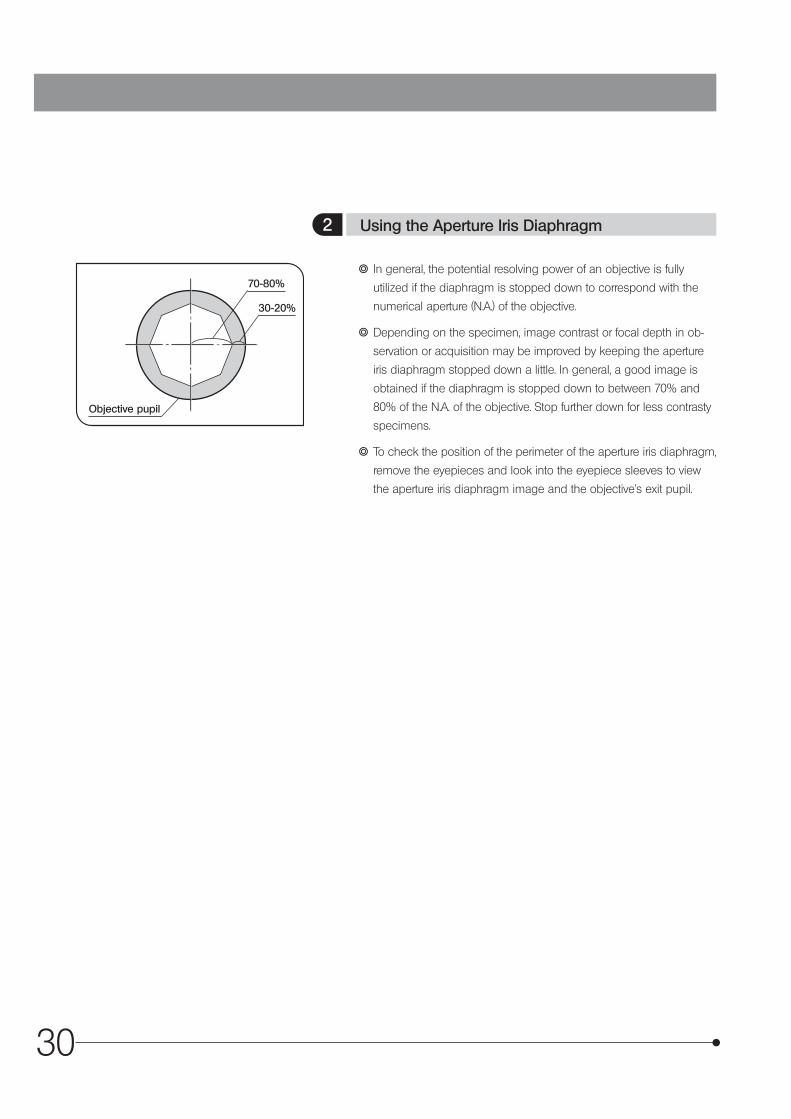
} In general, the potential resolving power of an objective is fully
utilized if the diaphragm is stopped down to correspond with the
numerical aperture (N.A.) of the objective.
} Depending on the specimen, image contrast or focal depth in ob-
servation or acquisition may be improved by keeping the aperture
iris diaphragm stopped down a little. In general, a good image is
obtained if the diaphragm is stopped down to between 70% and
80% of the N.A. of the objective. Stop further down for less contrasty
specimens.
} To check the position of the perimeter of the aperture iris diaphragm,
remove the eyepieces and look into the eyepiece sleeves to view
the aperture iris diaphragm image and the objective’s exit pupil.
2 Using the Aperture Iris Diaphragm
31
IX73
4-7 Oil- or Water-Immersion Objective
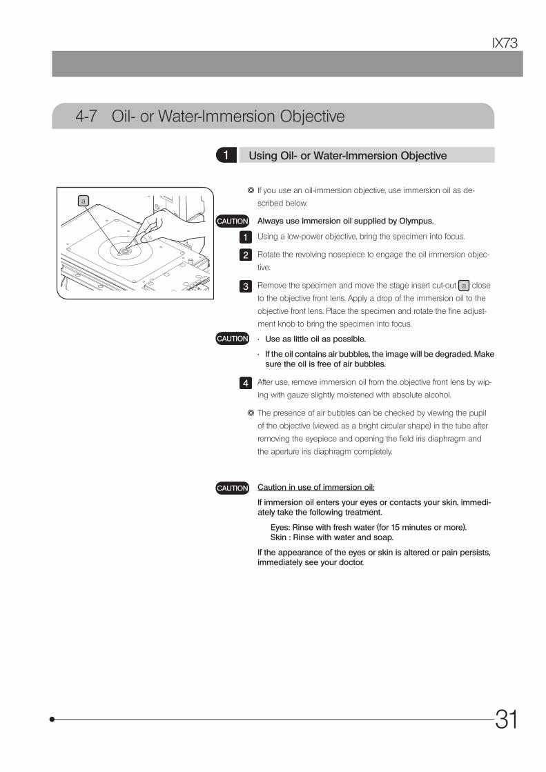
a } If you use an oil-immersion objective, use immersion oil as de-
scribed below.
Always use immersion oil supplied by Olympus.
Using a low-power objective, bring the specimen into focus.
Rotate the revolving nosepiece to engage the oil immersion objec-
tive.
Remove the specimen and move the stage insert cut-out a close
to the objective front lens. Apply a drop of the immersion oil to the
objective front lens. Place the specimen and rotate the fine adjust-
ment knob to bring the specimen into focus.
• Use as little oil as possible.
• If the oil contains air bubbles, the image will be degraded. Make sure the oil is free of air bubbles.
After use, remove immersion oil from the objective front lens by wip-
ing with gauze slightly moistened with absolute alcohol.
} The presence of air bubbles can be checked by viewing the pupil
of the objective (viewed as a bright circular shape) in the tube after
removing the eyepiece and opening the field iris diaphragm and
the aperture iris diaphragm completely.
Caution in use of immersion oil:
If immersion oil enters your eyes or contacts your skin, immedi-ately take the following treatment.
Eyes: Rinse with fresh water (for 15 minutes or more). Skin : Rinse with water and soap.
If the appearance of the eyes or skin is altered or pain persists, immediately see your doctor.
CAUTION
1
2
3
CAUTION
4
CAUTION
1 Using Oil- or Water-Immersion Objective
32
4-8 Objectives with Correction Collar
1a
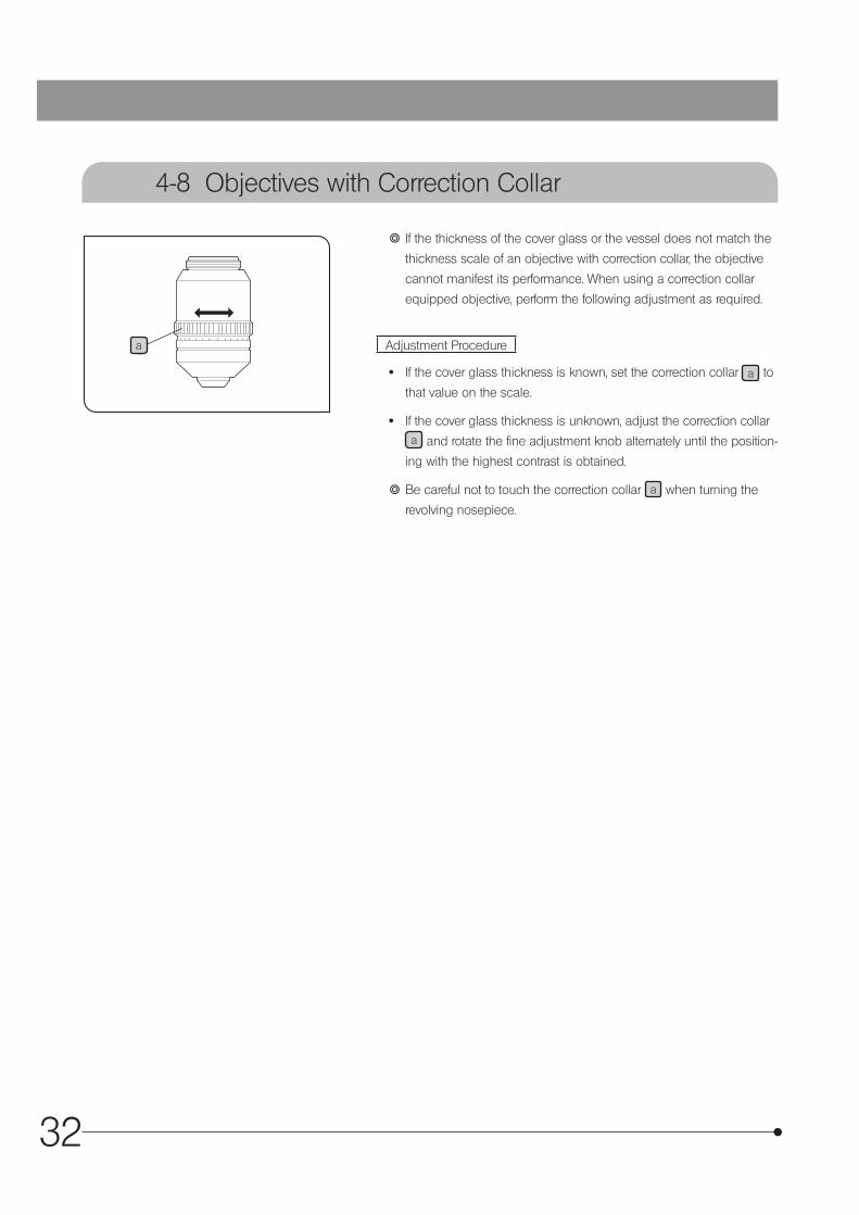
} If the thickness of the cover glass or the vessel does not match the
thickness scale of an objective with correction collar, the objective
cannot manifest its performance. When using a correction collar
equipped objective, perform the following adjustment as required.
Adjustment Procedure
· If the cover glass thickness is known, set the correction collar a to
that value on the scale.
· If the cover glass thickness is unknown, adjust the correction collar a and rotate the fine adjustment knob alternately until the position-
ing with the highest contrast is obtained.
} Be careful not to touch the correction collar a when turning the
revolving nosepiece.
33
IX73
5-1 Phase Contrast Observation
} A phase contrast objective, phase contrast optical element, and the U-CT30-2 centering telescope are required for phase contrast observation.
} If a DIC slider, analyzer or polarizer is engaged in the light path, disengage it.
With the IX3-LWUCDA or IX2-LWUCD
Optical Element Indication Applicable ObjectivesIX-PHL (small) PhL UPLFLN4XPHIX-PHC (small) PhC CPLN10XPH, LCACHN20XPH, CPLFLN10XPHIX-PH1 (small) Ph1 UPLFLN10X2PH, UPLFLN20XPH, LUCPLFLN20XPHIX-PH2 (small) Ph2 UCPLFLN20XPH, UPLFLN40XPH, LUCPLFLN40XPH, LUCPLFLN60XPH,
LCACHN40XPHIX-PH3 (large) Ph3 PLAPON60XOPH, UPLFLN60XOIPH, UPLSAPO100XOPH, UPLFLN100XO2PH
Example of attaching optical elements (IX3-LWUCDA)
Small Diameter: PH1, PHL, free or PH2, C, free
Large Diameter: PH3, DIC40, DIC60, DIC100
With the IX-ULWCD
} The IX-PHCU or IX-PH1U can be attached only in the Ph1 and PhC. (Do not remove the built-in elements.)
Optical Element Indication Applicable ObjectivesPHL (built-in) PhL UPLFLN4XPH
IX-PHCU PhC CPLN10XPH, LCACHN20XPH, CPLFLN10XPH
IX-PH1U Ph1 UPLFLN10XPH, UPLFLN20XPH, LUCPLFLN20XPH,
PH2 (built-in) Ph2 UCPLFLN20XPH, UPLFLN40XPH, LUCPLFLN40XPH, LUCPLFLN60XPH,
LCACHN40XPH
} When using the U-UCD8 or IX2-MLWCD, refer to the provided instructions.
} Insert the optical element (small) in the 30 mm position and the optical element (large) in the 38 mm position.
When observing the specimens in wells, it is recommended to use the IX-PHC to obtain the phase contrast effect
in a wide range of field of view.
5 OTHER OBSERVATION METHODS
1 Phase Contrast Optical Elements and Applicable Objectives
34
4
a
b
7
5
10
8
9
6
With the IX3-LWUCDA
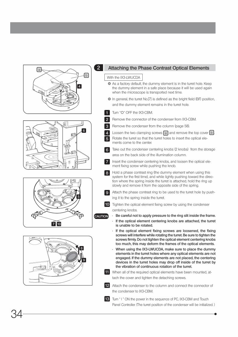
} As a factory default, the dummy element is in the turret hole. Keep the dummy element in a safe place because it will be used again when the microscope is transported next time.
} In general, the turret No.[7] is defined as the bright field (BF) position,
and the dummy element remains in the turret hole.
Turn “\” OFF the IX3-CBM.
Remove the connector of the condenser from IX3-CBM.
Remove the condenser from the column (page 58).
Loosen the two clamping screws a and remove the top cover b .
Rotate the turret so that the turret holes to insert the optical ele-ments come to the center.
Take out the condenser centering knobs (2 knobs) from the storage
area on the back side of the illumination column.
Insert the condenser centering knobs, and loosen the optical ele-ment fixing screw while pushing the knob.
Hold a phase contrast ring (the dummy element when using this system for the first time), and while lightly pushing toward the direc-tion where the spring inside the turret is attached, hold the ring up slowly and remove it from the opposite side of the spring.
Attach the phase contrast ring to be used to the turret hole by push-
ing it to the spring inside the turret.
Tighten the optical element fixing screw by using the condenser
centering knobs.
• Be careful not to apply pressure to the ring slit inside the frame.
• If the optical element centering knobs are attached, the turret is unable to be rotated.
• If the optical element fixing screws are loosened, the fixing screws will interfere while rotating the turret. Be sure to tighten the screws firmly. Do not tighten the optical element centering knobs too much, this may deform the frames of the optical elements.
• When using the IX3-LWUCDA, make sure to place the dummy elements in the turret holes where any optical elements are not engaged. If the dummy elements are not placed, the centering devices in the turret holes may drop off inside of the turret by the vibration of continuous rotation of the turret.
When all of the required optical elements have been mounted, at-
tach the cover and tighten the detaching screws.
Attach the condenser to the column and connect the connector of
the condenser to IX3-CBM.
Turn “ I ” ON the power in the sequence of PC, IX3-CBM and Touch
Panel Controller. (The turret position of the condenser will be initialized. )
1
2
3
45
6
7
8
9
10
CAUTION
11
12
13
2 Attaching the Phase Contrast Optical Elements
35
IX73
a
b
c
d
e
g
f h
i
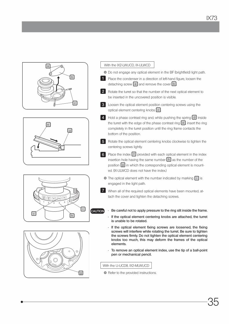
With the IX2-LWUCD, IX-ULWCD
} Do not engage any optical element in the BF (brightfield) light path.
Place the condenser in a direction of left-hand figure, loosen the
detaching screw a and remove the cover b .
Rotate the turret so that the number of the next optical element to
be inserted in the uncovered position is visible.
Loosen the optical element position centering screws using the
optical element centering knobs c .
Hold a phase contrast ring and, while pushing the spring d inside
the turret with the edge of the phase contrast ring e , insert the ring
completely in the turret position until the ring frame contacts the
bottom of the position.
Rotate the optical element centering knobs clockwise to tighten the
centering screws lightly.
Place the index f provided with each optical element in the index
insertion hole having the same number h as the number of the
position g in which the corresponding optical element is mount-
ed. (IX-ULWCD does not have the index.)
} The optical element with the number indicated by marking i is
engaged in the light path.
When all of the required optical elements have been mounted, at-
tach the cover and tighten the detaching screws.
• Be careful not to apply pressure to the ring slit inside the frame.
• If the optical element centering knobs are attached, the turret is unable to be rotated.
• If the optical element fixing screws are loosened, the fixing screws will interfere while rotating the turret. Be sure to tighten the screws firmly. Do not tighten the optical element centering knobs too much, this may deform the frames of the optical elements.
• To remove an optical element index, use the tip of a ball-point pen or mechanical pencil.
With the U-UCD8, IX2-MLWUCD
} Refer to the provided instructions.
1
2
3
4
5
6
7
CAUTION
36
ab
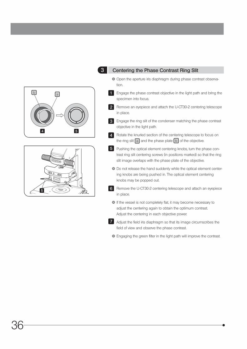
} Open the aperture iris diaphragm during phase contrast observa-
tion.
Engage the phase contrast objective in the light path and bring the
specimen into focus.
Remove an eyepiece and attach the U-CT30-2 centering telescope
in place.
Engage the ring slit of the condenser matching the phase contrast
objective in the light path.
Rotate the knurled section of the centering telescope to focus on
the ring slit a and the phase plate b of the objective.
Pushing the optical element centering knobs, turn the phase con-
trast ring slit centering screws (in positions marked) so that the ring
slit image overlaps with the phase plate of the objective.
} Do not release the hand suddenly while the optical element center-
ing knobs are being pushed in. The optical element centering
knobs may be popped out.
Remove the U-CT30-2 centering telescope and attach an eyepiece
in place.
} If the vessel is not completely flat, it may become necessary to
adjust the centering again to obtain the optimum contrast.
Adjust the centering in each objective power.
Adjust the field iris diaphragm so that its image circumscribes the
field of view and observe the phase contrast.
} Engaging the green filter in the light path will improve the contrast.
1
2
3
4
5
6
7
3 Centering the Phase Contrast Ring Slit
4 5
5
37
IX73
5-2 Differential Interference Contrast Observation
} If a plastic dish is used, the normal optical performance of DIC observation cannot be manifested due to the polar-ization characteristic of the dish. Use a glass dish.
} For simultaneous observation with reflected fluorescence observation, refer to the separate instruction manual.
} DIC optical elements, a DIC slider, analyzer, and polarizer are required for DIC observation.
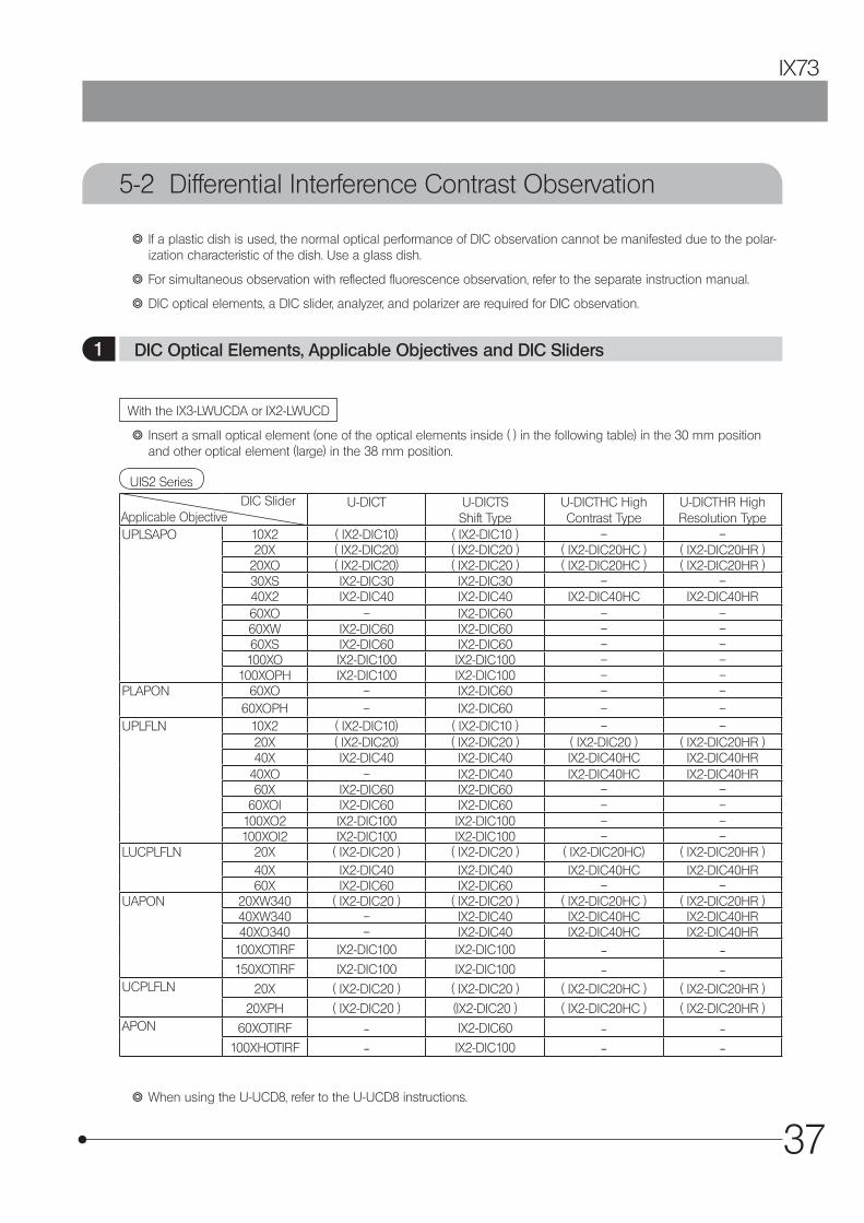
With the IX3-LWUCDA or IX2-LWUCD
UIS2 Series
} Insert a small optical element (one of the optical elements inside ( ) in the following table) in the 30 mm position and other optical element (large) in the 38 mm position.
U-DICT U-DICTS Shift Type
U-DICTHC High Contrast Type
U-DICTHR High Resolution Type
UPLSAPO 10X2 ( IX2-DIC10) ( IX2-DIC10 ) – –20X ( IX2-DIC20) ( IX2-DIC20 ) ( IX2-DIC20HC ) ( IX2-DIC20HR )
20XO ( IX2-DIC20) ( IX2-DIC20 ) ( IX2-DIC20HC ) ( IX2-DIC20HR )30XS IX2-DIC30 IX2-DIC30 – –40X2 IX2-DIC40 IX2-DIC40 IX2-DIC40HC IX2-DIC40HR60XO – IX2-DIC60 – –60XW IX2-DIC60 IX2-DIC60 – –60XS IX2-DIC60 IX2-DIC60 – –100XO IX2-DIC100 IX2-DIC100 – –
100XOPH IX2-DIC100 IX2-DIC100 – –PLAPON 60XO – IX2-DIC60 – –
60XOPH – IX2-DIC60 – –UPLFLN 10X2 ( IX2-DIC10) ( IX2-DIC10 ) – –
20X ( IX2-DIC20) ( IX2-DIC20 ) ( IX2-DIC20 ) ( IX2-DIC20HR )40X IX2-DIC40 IX2-DIC40 IX2-DIC40HC IX2-DIC40HR
40XO – IX2-DIC40 IX2-DIC40HC IX2-DIC40HR60X IX2-DIC60 IX2-DIC60 – –
60XOI IX2-DIC60 IX2-DIC60 – –100XO2 IX2-DIC100 IX2-DIC100 – –100XOI2 IX2-DIC100 IX2-DIC100 – –
LUCPLFLN 20X ( IX2-DIC20 ) ( IX2-DIC20 ) ( IX2-DIC20HC) ( IX2-DIC20HR )40X IX2-DIC40 IX2-DIC40 IX2-DIC40HC IX2-DIC40HR60X IX2-DIC60 IX2-DIC60 – –
UAPON 20XW340 ( IX2-DIC20 ) ( IX2-DIC20 ) ( IX2-DIC20HC ) ( IX2-DIC20HR )40XW340 – IX2-DIC40 IX2-DIC40HC IX2-DIC40HR40XO340 – IX2-DIC40 IX2-DIC40HC IX2-DIC40HR
100XOTIRF IX2-DIC100 IX2-DIC100 — —
150XOTIRF IX2-DIC100 IX2-DIC100 — —UCPLFLN 20X ( IX2-DIC20 ) ( IX2-DIC20 ) ( IX2-DIC20HC ) ( IX2-DIC20HR )
20XPH ( IX2-DIC20 ) (IX2-DIC20 ) ( IX2-DIC20HC ) ( IX2-DIC20HR )APON 60XOTIRF — IX2-DIC60 — —
100XHOTIRF — IX2-DIC100 — —
} When using the U-UCD8, refer to the U-UCD8 instructions.
DIC SliderApplicable Objective
1 DIC Optical Elements, Applicable Objectives and DIC Sliders
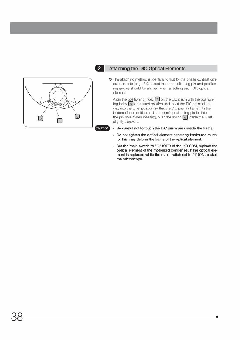
38
ab
c
} The attaching method is identical to that for the phase contrast opti-cal elements (page 34), except that the positioning pin and position-ing groove should be aligned when attaching each DIC optical element.
Align the positioning index a on the DIC prism with the position-ing index b on a turret position and insert the DIC prism all the way into the turret position so that the DIC prism’s frame hits the bottom of the position and the prism’s positioning pin fits into the pin hole. When inserting, push the spring c inside the turret slightly sideward.
• Be careful not to touch the DIC prism area inside the frame.
• Do not tighten the optical element centering knobs too much, for this may deform the frame of the optical element.
• Set the main switch to "\” (OFF) of the IX3-CBM, replace the optical element of the motorized condenser. If the optical ele-ment is replaced while the main switch set to “ I” (ON), restart the microscope.
CAUTION
2 Attaching the DIC Optical Elements
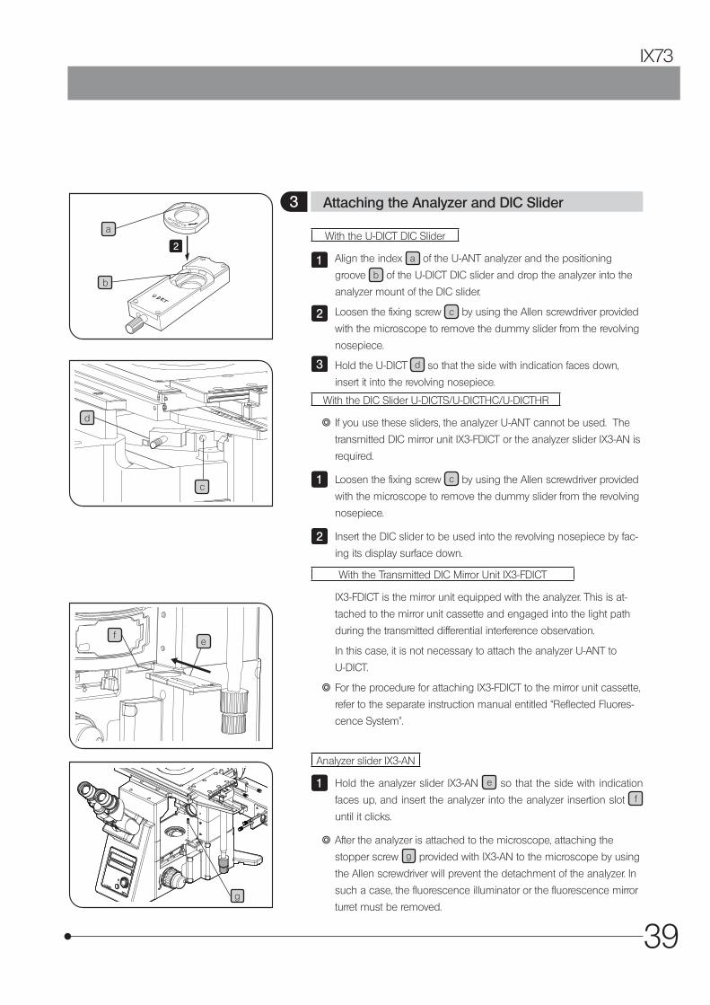
39
IX73
a
b
d
Analyzer slider IX3-AN
Hold the analyzer slider IX3-AN e so that the side with indication
faces up, and insert the analyzer into the analyzer insertion slot f
until it clicks.
} After the analyzer is attached to the microscope, attaching the
stopper screw g provided with IX3-AN to the microscope by using
the Allen screwdriver will prevent the detachment of the analyzer. In
such a case, the fluorescence illuminator or the fluorescence mirror
turret must be removed.
1
e
With the U-DICT DIC Slider
Align the index a of the U-ANT analyzer and the positioning
groove b of the U-DICT DIC slider and drop the analyzer into the
analyzer mount of the DIC slider.
Loosen the fixing screw c by using the Allen screwdriver provided
with the microscope to remove the dummy slider from the revolving
nosepiece.
Hold the U-DICT d so that the side with indication faces down,
insert it into the revolving nosepiece.
With the DIC Slider U-DICTS/U-DICTHC/U-DICTHR
} If you use these sliders, the analyzer U-ANT cannot be used. The
transmitted DIC mirror unit IX3-FDICT or the analyzer slider IX3-AN is
required.
Loosen the fixing screw c by using the Allen screwdriver provided
with the microscope to remove the dummy slider from the revolving
nosepiece.
Insert the DIC slider to be used into the revolving nosepiece by fac-
ing its display surface down.
With the Transmitted DIC Mirror Unit IX3-FDICT
IX3-FDICT is the mirror unit equipped with the analyzer. This is at-
tached to the mirror unit cassette and engaged into the light path
during the transmitted differential interference observation.
In this case, it is not necessary to attach the analyzer U-ANT to
U-DICT.
} For the procedure for attaching IX3-FDICT to the mirror unit cassette,
refer to the separate instruction manual entitled “Reflected Fluores-
cence System”.
1
2
3
1
2
3 Attaching the Analyzer and DIC Slider
f
g
c
2
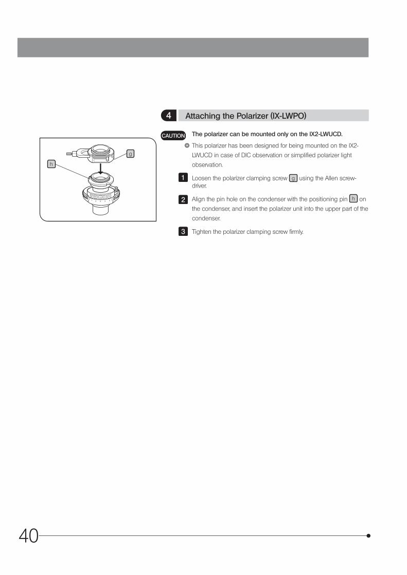
40
g
h
The polarizer can be mounted only on the IX2-LWUCD.
} This polarizer has been designed for being mounted on the IX2-
LWUCD in case of DIC observation or simplified polarizer light
observation.
Loosen the polarizer clamping screw g using the Allen screw-driver.
Align the pin hole on the condenser with the positioning pin h on
the condenser, and insert the polarizer unit into the upper part of the
condenser.
Tighten the polarizer clamping screw firmly.
CAUTION
1
2
3
4 Attaching the Polarizer (IX-LWPO)

41
IX73
a
when using IX3-LWUCDA
d
bwhen using IX-LWPO
when using IX3-LWUCDA
c
d
e
f
Rotate the condenser’s turret for the BF (brightfield) light path (with
no optical element engaged in the light path).
When IX3-LWUCDA is used, push the button a of IX3-LWUCDA to
engage the polarizer in the light path.
When IX-LWPO is used, move the polarizer detaching lever b on
the IX-LWPO polarizer to engage the polarizer in the light path.
Engage the 10X objective in the light path, place an optimum speci-
men for brightfield observation on the stage, bring the specimen
into approximate and remove the specimen out of the light path.
Refer to page 39, engage the DIC slider and the analyzer in the light
path.
Remove the eyepieces from the observation tube, look into the
observation tube.
Move the prism movement knob e of the DIC slider in the clock-
wise direction around the axis until the knob is stopped. First a
black interference stripe then a rainbow-colored interference stripe
will be observed. Stop the knob at the position in which the black
interference stripe can be seen. (State of f )
When IX3-LWUCDA is used, loosen the polarizer rotation knob d
by rotating the clamping knob c in the clockwise direction until
the knob stops.
When IX-LWPO is used, loosen the clamping of the polarizer rota-
tion/clamping knob by rotating slightly the polarizer rotation/clamp-
ing knob d in a counter-clockwise direction.
While looking into the observation tube, rotate the polarizer rotation/
clamping knob d on the polarizer unit horizontally until the black
interference stripe becomes darkest. This is the cross-nicol position.
After determining the position, clamp the polarizer.
When the IX3-LWUCDA is used, rotate the clamping knob c in
the counterclockwise direction around the axis until the knob is
stopped.
When the IX-LWPO is used, rotate the polarizer rotation/clamping
knob d in a clockwise direction until the knob stops.
1
2
3
4
5
6
7
8
9
5 Cross-Nicol Adjustment
42
Rotate the condenser turret to engage the suitable optical element
for the objective in use in the light path.
Engage the objective to be used in the light path.
Place the specimen on the stage and bring the specimen into
focus by moving the objective up or down.
Adjust the field iris diaphragm so that its image circumscribes the
field of view.
Adjust the aperture iris diaphragm to enhance the contrast.
Engage the DIC slider in the light path.
Move the prism movement knob of the DIC slider to select the inter-
ference color that can provide the optimum contrast in accordance
with the specimen.
U-DICT : The background interference color is continuously
variable from the gray sensitive color to purple sen-
sitive color.
U-DICTS :
U-DICTHC :
U-DICTHR :
} With sensitive color observation using the U-UCD8, engage the
UUCDTP530 1 plate (sensitive color plate) in the light path.
· Setting the background color to dark enables an observation
like darkfield observation.
· Setting the background color to gray provides observation with
high contrast and 3D feeling with the gray sensitive color with
which the sensitivity is highest.
· Setting the background color to gray allows very small change
in phase to be observed as a change in color.
· There is a directional characteristic with the detection sensitivity
because of the configuration of the DIC prism. As a result, the
contrast may sometimes be improved by rotating the specimen
on the stage.
For simultaneous observation with reflected fluorescence ob-servation, refer to the instruction manual entitled “REFLECTED FLUORESCENCE SYSTEM”.
1
2
3
4
5
6
7
The background interference color is con-
tinuously variable from black to light gray.
CAUTION
6 Observation Method
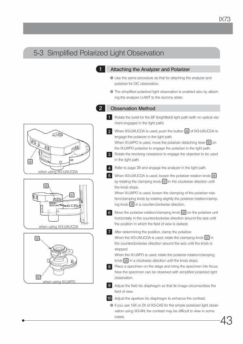
43
IX73
5-3 Simplified Polarized Light Observation
a
d
bwhen using IX-LWPO
when using IX3-LWUCDA
c
d
when using IX3-LWUCDA
} Use the same procedure as that for attaching the analyzer and
polarizer for DIC observation.
} The simplified polarized light observation is enabled also by attach-
ing the analyzer U-ANT to the dummy slider.
Rotate the turret for the BF (brightfield) light path (with no optical ele-
ment engaged in the light path).
When IX3-LWUCDA is used, push the button a of IX3-LWUCDA to
engage the polarizer in the light path.
When IX-LWPO is used, move the polarizer detaching lever b on
the IX-LWPO polarizer to engage the polarizer in the light path.
Rotate the revolving nosepiece to engage the objective to be used
in the light path.
Refer to page 39 and engage the analyzer in the light path.
When IX3-LWUCDA is used, loosen the polarizer rotation knob d
by rotating the clamping knob c in the clockwise direction until
the knob stops.
When IX-LWPO is used, loosen the clamping of the polarizer rota-
tion/clamping knob by rotating slightly the polarizer rotation/clamp-
ing knob d in a counter-clockwise direction.
Move the polarizer rotation/clamping knob d on the polarizer unit
horizontally in the counterclockwise direction around the axis until
the position in which the field of view is darkest.
After determining the position, clamp the polarizer.
When the IX3-LWUCDA is used, rotate the clamping knob c in
the counterclockwise direction around the axis until the knob is
stopped.
When the IX-LWPO is used, rotate the polarizer rotation/clamping
knob d in a clockwise direction until the knob stops.
Place a specimen on the stage and bring the specimen into focus.
Now the specimen can be observed with simplified polarized light
observation.
Adjust the field iris diaphragm so that its image circumscribes the
field of view.
Adjust the aperture iris diaphragm to enhance the contrast.
} If you use 1.6X or 2X of IX3-CAS for the simple polarized light obser-
vation using IX3-AN, the contrast may be difficult to view in some
cases.
1
22
3
4
5
6
7
8
9
10
1 Attaching the Analyzer and Polarizer
2 Observation Method

44
5-4 Reflected Light Fluorescence Observation (Separate Manual)
5-5 Relief Contrast Observation (Separate Manual)
} Refer to the separate instruction manual (REFLECTED FLUORESCENCE SYSTEM).
} Refer to the separate instruction manual (IX2-MLWCD).
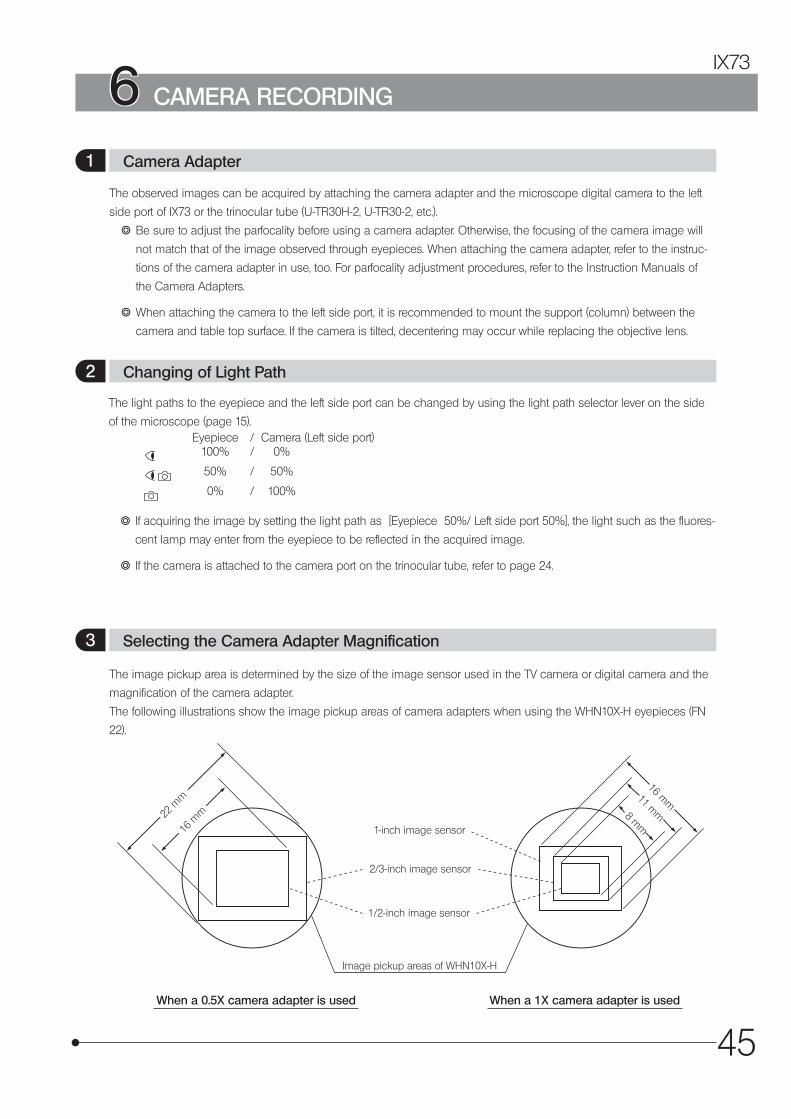
45
IX73
The observed images can be acquired by attaching the camera adapter and the microscope digital camera to the left
side port of IX73 or the trinocular tube (U-TR30H-2, U-TR30-2, etc.).
} Be sure to adjust the parfocality before using a camera adapter. Otherwise, the focusing of the camera image will
not match that of the image observed through eyepieces. When attaching the camera adapter, refer to the instruc-
tions of the camera adapter in use, too. For parfocality adjustment procedures, refer to the Instruction Manuals of
the Camera Adapters.
} When attaching the camera to the left side port, it is recommended to mount the support (column) between the
camera and table top surface. If the camera is tilted, decentering may occur while replacing the objective lens.
The light paths to the eyepiece and the left side port can be changed by using the light path selector lever on the side
of the microscope (page 15).Eyepiece / Camera (Left side port)
100% / 0%
50% / 50%
0% / 100%
} If acquiring the image by setting the light path as [Eyepiece 50%/ Left side port 50%], the light such as the fluores-
cent lamp may enter from the eyepiece to be reflected in the acquired image.
} If the camera is attached to the camera port on the trinocular tube, refer to page 24.
The image pickup area is determined by the size of the image sensor used in the TV camera or digital camera and the
magnification of the camera adapter.
The following illustrations show the image pickup areas of camera adapters when using the WHN10X-H eyepieces (FN
22).
8 mm
11 mm
16 mm
16 m
m22 m
m
1-inch image sensor
2/3-inch image sensor
1/2-inch image sensor
Image pickup areas of WHN10X-H
When a 0.5X camera adapter is used When a 1X camera adapter is used
6 CAMERA RECORDING
1 Camera Adapter
2 Changing of Light Path
3 Selecting the Camera Adapter Magnification
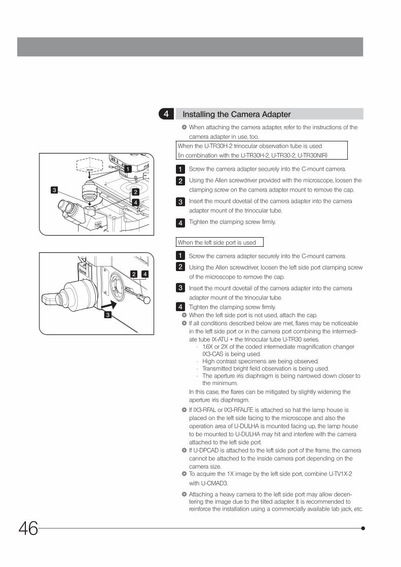
46
} When attaching the camera adapter, refer to the instructions of the
camera adapter in use, too.
When the U-TR30H-2 trinocular observation tube is used
(in combination with the U-TR30H-2, U-TR30-2, U-TR30NIR)
Screw the camera adapter securely into the C-mount camera.
Using the Allen screwdriver provided with the microscope, loosen the
clamping screw on the camera adapter mount to remove the cap.
Insert the mount dovetail of the camera adapter into the camera
adapter mount of the trinocular tube.
Tighten the clamping screw firmly.
When the left side port is used
Screw the camera adapter securely into the C-mount camera.
Using the Allen screwdriver, loosen the left side port clamping screw
of the microscope to remove the cap.
Insert the mount dovetail of the camera adapter into the camera
adapter mount of the trinocular tube.
Tighten the clamping screw firmly. } When the left side port is not used, attach the cap. } If all conditions described below are met, flares may be noticeable in the left side port or in the camera port combining the intermedi-ate tube IX-ATU + the trinocular tube U-TR30 series.
• 1.6X or 2X of the coded intermediate magnification changer IX3-CAS is being used.
• High contrast specimens are being observed.• Transmitted bright field observation is being used.• The aperture iris diaphragm is being narrowed down closer to
the minimum.In this case, the flares can be mitigated by slightly widening the aperture iris diaphragm.
} If IX3-RFAL or IX3-RFALFE is attached so hat the lamp house is placed on the left side facing to the microscope and also the operation area of U-DULHA is mounted facing up, the lamp house to be mounted to U-DULHA may hit and interfere with the camera attached to the left side port.
} If U-DPCAD is attached to the left side port of the frame, the camera cannot be attached to the inside camera port depending on the camera size.
} To acquire the 1X image by the left side port, combine U-TV1X-2
with U-CMAD3.
} Attaching a heavy camera to the left side port may allow decen-tering the image due to the tilted adapter. It is recommended to reinforce the installation using a commercially available lab jack, etc.
1
2
3
4
1
2
3
4
4 Installing the Camera Adapter
1
2
2 4
4
3
3
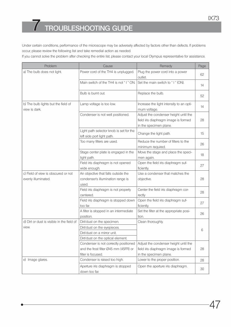
47
IX73
Problem Cause Remedy Page
a) The bulb does not light. Power cord of the TH4 is unplugged. Plug the power cord into a power
outlet.62
Main switch of the TH4 is not “ I ” ON. Set the main switch to “ I ” (ON).14
Bulb is burnt out. Replace the bulb.52
b) The bulb lights but the field of
view is dark.
Lamp voltage is too low. Increase the light intensity to an opti-
mum voltage.14
Condenser is not well positioned. Adjust the condenser height until the
field iris diaphragm image is formed
in the specimen plane.
28
Light path selector knob is set for the
left side port light path.Change the light path. 15
Too many filters are used. Reduce the number of filters to the
minimum required.26
Stage center plate is engaged in the
light path.
Move the stage and place the speci-
men again.18
Field iris diaphragm is not opened
wide enough.
Open the field iris diaphragm suf-
ficiently.27
c) Field of view is obscured or not
evenly illuminated.
An objective that falls outside the
condenser’s illumination range is
used.
Use a condenser that matches the
objective. 28
Field iris diaphragm is not properly
centered.
Center the field iris diaphragm cor-
rectly28
Field iris diaphragm is stopped down
too far.
Open the field iris diaphragm suf-
ficiently.27
A filter is stopped in an intermediate
position.
Set the filter at the appropriate posi-
tion.26
d) Dirt or dust is visible in the field of
view.
Dirt/dust on the specimen. Clean thoroughly.
6Dirt/dust on the eyepieces.
Dirt/dust on a mirror unit.
Dirt/dust on the optical element.
Condenser is not correctly positioned
and the frost filter Ø45 mm (45FR) or
filter is focused.
Adjust the condenser height until the
field iris diaphragm image is formed
in the specimen plane.
28
e) Image glares. Condenser is raised too high. Lower to the proper position. 28
Aperture iris diaphragm is stopped
down too far.
Open the aperture iris diaphragm.30
Under certain conditions, performance of the microscope may be adversely affected by factors other than defects. If problems
occur, please review the following list and take remedial action as needed.
If you cannot solve the problem after checking the entire list, please contact your local Olympus representative for assistance.
7 TROUBLESHOOTING GUIDE
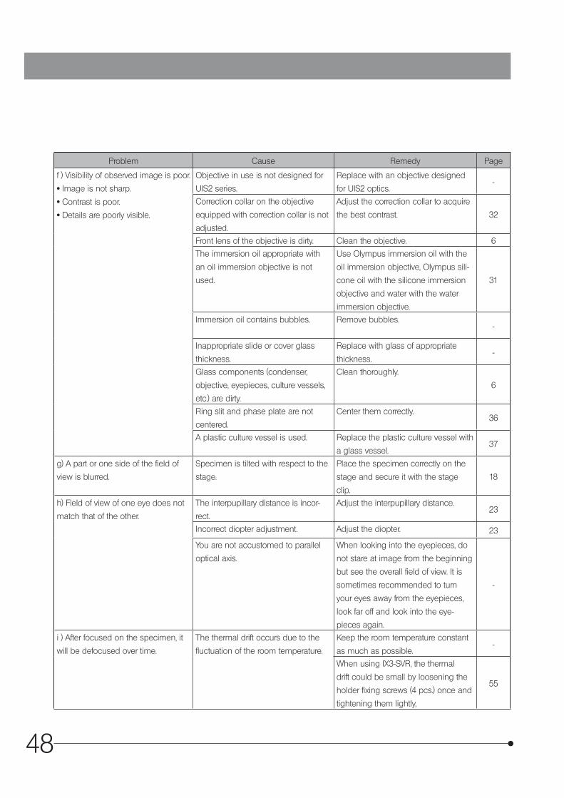
48
Problem Cause Remedy Page
f ) Visibility of observed image is poor.
· Image is not sharp.
· Contrast is poor.
· Details are poorly visible.
Objective in use is not designed for
UIS2 series.
Replace with an objective designed
for UIS2 optics.-
Correction collar on the objective
equipped with correction collar is not
adjusted.
Adjust the correction collar to acquire
the best contrast. 32
Front lens of the objective is dirty. Clean the objective. 6
The immersion oil appropriate with
an oil immersion objective is not
used.
Use Olympus immersion oil with the
oil immersion objective, Olympus sili-
cone oil with the silicone immersion
objective and water with the water
immersion objective.
31
Immersion oil contains bubbles. Remove bubbles.-
Inappropriate slide or cover glass
thickness.
Replace with glass of appropriate
thickness.-
Glass components (condenser,
objective, eyepieces, culture vessels,
etc.) are dirty.
Clean thoroughly.
6
Ring slit and phase plate are not
centered.
Center them correctly.36
A plastic culture vessel is used. Replace the plastic culture vessel with
a glass vessel.37
g) A part or one side of the field of
view is blurred.
Specimen is tilted with respect to the
stage.
Place the specimen correctly on the
stage and secure it with the stage
clip.
18
h) Field of view of one eye does not
match that of the other.
The interpupillary distance is incor-
rect.
Adjust the interpupillary distance.23
Incorrect diopter adjustment. Adjust the diopter. 23
You are not accustomed to parallel
optical axis.
When looking into the eyepieces, do
not stare at image from the beginning
but see the overall field of view. It is
sometimes recommended to turn
your eyes away from the eyepieces,
look far off and look into the eye-
pieces again.
-
i ) After focused on the specimen, it
will be defocused over time.
The thermal drift occurs due to the
fluctuation of the room temperature.
Keep the room temperature constant
as much as possible.-
When using IX3-SVR, the thermal
drift could be small by loosening the
holder fixing screws (4 pcs.) once and
tightening them lightly,
55

49
IX73
Item SpecificationOptical system UIS2 optical systemMicroscope Frame
IX73P1F
IX73P2F
Motorized light path selection1 100% for observation light path2 50% for observation light path, 50% for left side port3 100% for left side port
Focusing movable range Upper side: 6.5 mm or more from the original position Lower side: 3 mm or more from the original position Original position: 1 mm above the stage surfaceLeft side port image magnification: 1X
Illumination Column Column for installing the lamp housing, with 30° tilting mechanism.Condenser holder up/down movement range: 88 mmCondenser refocusing mechanism is available.Designated bulb 12 V, 100 W long-life halogen bulb 12V100WHAL-L (PHILIPS 7724)
Power supply: Halogen lamp power supply unit TH4Observation
Tube
Type U-BI90 U-TBI90 U-TR30-2/U-TR30H-2
U-TR30NIR
Binocular Tilting binocular Trinocular TrinocularField No. 22Tube inclination 45° 35° to 85° 30° 30°Interpupillary distance adjustment
50 to 76 mm
Diopter adjustment range - 5 to + 5 diopIntermediate tube U-EPA2, GX-SPU, U-CA, etc. IX-ATULight path selection
None 3 steps:1 BI 100%2 BI 20%,
Camera 80%3 Camera 100%
3 steps:@ BI 100%2 BI 50%,
Camera 50%3 Camera 100%
Stage Type BX3-SSU IX3-SVR IX2-SPSize 250.5 mm (D) x 268.2 mm (W) 240 mm (D) x 444.5 mm (W) 240 mm (D) x 232 mm (W)Movement mechanism
• Ultrasonic drive• Maximum speed 30 mm/sec• Single rough/fine adjustment
handle (XY controller)
• X- and Y-axis knob with adjust-able tension.
• Right long axis handle (can be mounted by reversing the right and left)
Not available
Movement range: 52 mm vertical (Y), 76 mm horizontal (X).
Movement range: 75 mm vertical (Y), 114 mm horizontal (X).
Movement range:(Combined with IX-MVR)
85 mm vertical (Y), 130 mm horizontal (X).
Option Replaceable center plate (Ø110 mm)
Replaceable center plate (Ø110 mm)
Replaceable center plate (Ø110 mm)
Condenser Type IX3-LWUCDA IX2-LWUCD IX2-MLWCD IX-ULWCD U-UCD8 (Used together with IX-ADUCD)
NA 0.55 0.55 0.5 0.3 When a dry top lens is used :0.9When an oil top lens is used :1.4
WD 27 mm 27 mm 45 mm 73 mm When a dry top lens is used :1.5 mmWhen an oil top lens is used :0.6 mm
Turret small hole 3, large hole 4
small hole 3, large hole 2
4 4small hole 3, large hole 5
Operating
environment
· Indoor use.· Altitude: Max. 2000 meters· Ambient temperature: 5 to 40 °C (41 to 104 °F)· Maximum relative humidity: 80 % for temperatures up to 31 °C (88 °F) (without condensation)
In case of over 31 °C (88 °F), the relative humidity is decreased linearly through 70 % at 34 °C (93 °F), 60 % at 37 °C (99 °F), and to 50 % at 40 °C (104 °F).
· Supply voltage fluctuations: ±10%· Pollution degree: 2 (in accordance with IEC60664-1)· Installation/Overvoltage category: II (in accordance with IEC60664-1)
Transportation/storage environment
· Temperature: Min. -25°C, Max. 65°C· Humidity: Min. 0%, Max. 90% (without condensation)
8 SPECIFICATIONS
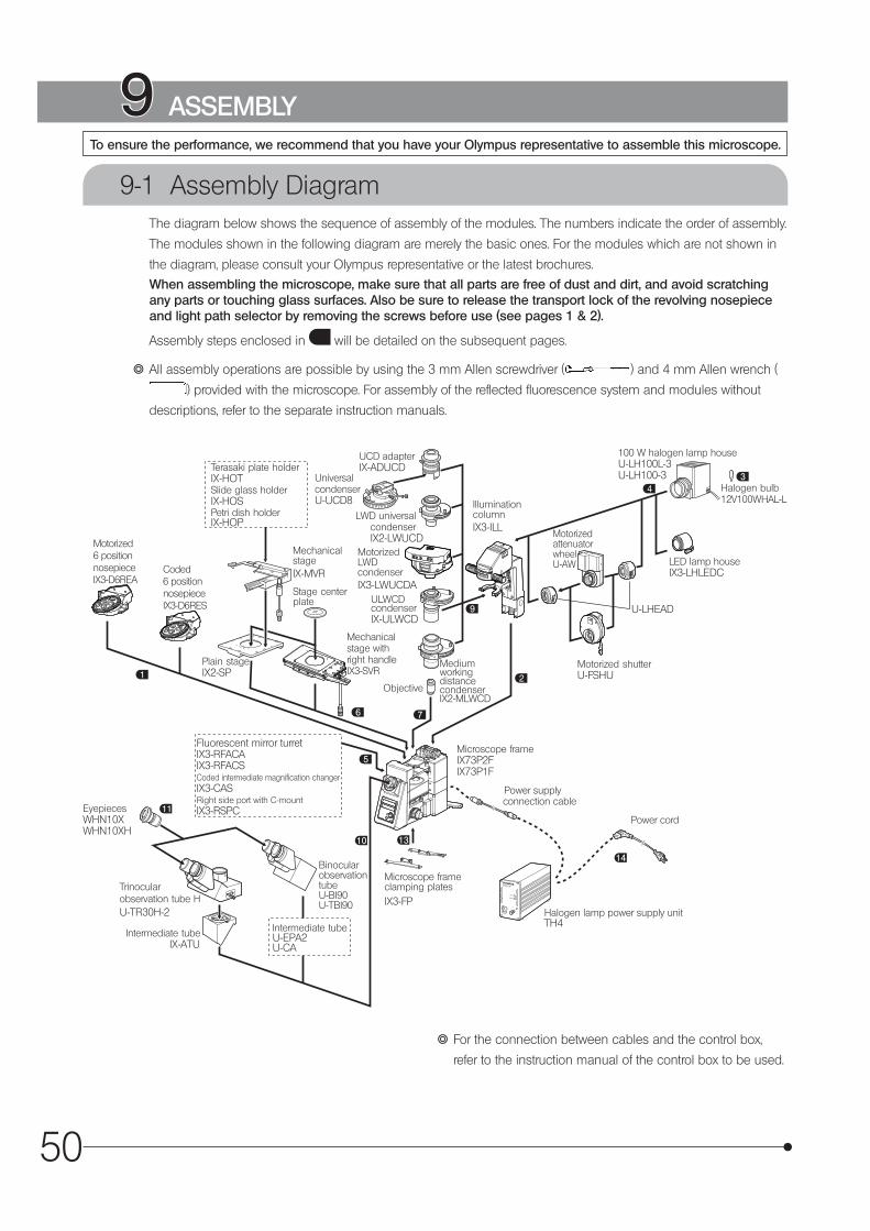
50
9-1 Assembly DiagramThe diagram below shows the sequence of assembly of the modules. The numbers indicate the order of assembly.
The modules shown in the following diagram are merely the basic ones. For the modules which are not shown in
the diagram, please consult your Olympus representative or the latest brochures.
When assembling the microscope, make sure that all parts are free of dust and dirt, and avoid scratching any parts or touching glass surfaces. Also be sure to release the transport lock of the revolving nosepiece and light path selector by removing the screws before use (see pages 1 & 2).
Assembly steps enclosed in will be detailed on the subsequent pages.
} All assembly operations are possible by using the 3 mm Allen screwdriver ( ) and 4 mm Allen wrench (
) provided with the microscope. For assembly of the reflected fluorescence system and modules without
descriptions, refer to the separate instruction manuals.
9 ASSEMBLYTo ensure the performance, we recommend that you have your Olympus representative to assemble this microscope.
} For the connection between cables and the control box,
refer to the instruction manual of the control box to be used.
6
3
1
10 13
9
5
11
7
14
Terasaki plate holderIX-HOTSlide glass holderIX-HOSPetri dish holderIX-HOP
MechanicalstageIX-MVR
Stage centerplate
Plain stageIX2-SP
Mechanicalstage withright handleIX3-SVR
UCD adapterIX-ADUCD
UniversalcondenserU-UCD8
LWD universalcondenserIX2-LWUCD
MotorizedLWDcondenserIX3-LWUCDA
ULWCDcondenserIX-ULWCD
Objective
IlluminationcolumnIX3-ILL
100 W halogen lamp houseU-LH100L-3U-LH100-3
Halogen bulb12V100WHAL-L
Motorized shutterU-FSHU
Microscope frameIX73P2FIX73P1F
Power cord
Microscope frameclamping platesIX3-FP
Intermediate tubeU-EPA2U-CA
BinocularobservationtubeU-BI90U-TBI90
Intermediate tubeIX-ATU
Trinocularobservation tube HU-TR30H-2
EyepiecesWHN10XWHN10XH
MediumworkingdistancecondenserIX2-MLWCD
U-LHEAD
MotorizedattenuatorwheelU-AW LED lamp house
IX3-LHLEDC
Fluorescent mirror turretIX3-RFACAIX3-RFACSCoded intermediate magnification changerIX3-CASRight side port with C-mountIX3-RSPC
Halogen lamp power supply unitTH4
Power supplyconnection cable
Motorized6 positionnosepieceIX3-D6REA
Coded6 positionnosepieceIX3-D6RES

51
IX73
IX3-D6REA, IX3-D6RES
Loosen the cover fixing screw a (2 positions) by using the Phillips
screwdriver, and remove the cover b .
1
Insert the revolving nosepiece slowly into the positioning pins c (2
positions) in the upper area of the microscope.
As the mounting holes of the positioning pins are small, insert the revolving nosepiece into the positioning pins carefully from the above paying attention not to tilt the revolving nosepiece.
2
CAUTION
Tighten the revolving nosepiece fixing screws d (5 positions) by using
the Allen wrench provided with the microscope.
3
Place the cover b over the revolving nosepiece, and tighten the
cover fixing screws a (2 positions) by using the Phillips screwdriver.
4
ab
c
d
a
b
To ensure the performance, we recommend that you have your Olympus representative to assemble the revolving nosepiece.
CAUTION
1 Attaching the revolving nosepiece
9-2 Detailed Assembly Procedures
2
4

52
a
bc
d
d
Aligning the two guide holes on the illumination column with the
two protruding positioning pins on the microscope, gently fit the
column onto the microscope from the above.
While holding the illumination column with one hand, insert the four
provided Allen screws into the screw holes. Then tighten the screws
with the provided Allen wrench.
Do not tighten the screws with the illumination column inclined. Doing so may damage the screw sections.
1
2
CAUTION
} The designated bulb model is the 12V100WHAL-L (PHILIPS 7724)
halogen bulb.
Fully loosen the clamping screw at the top of the halogen lamp
housing using the Allen screwdriver provided with the microscope.
Lift up the halogen lamp housing to remove it.
Tilt the bulb socket by 90° in the direction of the arrow.
While pushing down the bulb clamping lever a , hold the halogen
bulb b with gloves or a piece of gauze, insert the bulb pins c
straight and fully into the pin position d on the lamp socket.
Then return the lamp clamping lever gently back to the original
position to clamp the bulb.
1
2
3
4
To prevent reduced bulb life or cracking, do not touch the bulb with bare hands. If fingerprints are accidentally left on the bulb, wipe the bulb with a dry soft cloth.
Fit the halogen lamp housing from up and tighten the clamping
screw by applying downward pressure.
Caution for Bulb Replacement During or Right After Use
The bulb, lamp housing and areas near these will be extremely hot during and right after use. Set the main switch to “ \ ” (OFF), disconnect the power cord from the wall outlet, then allow the old bulb and lamp housing to cool before replacing the bulb with a new of the designated type.
CAUTION
5
2 Mounting the Illumination Column
3 Attaching the Halogen Bulb
1
2
1 5
2
3
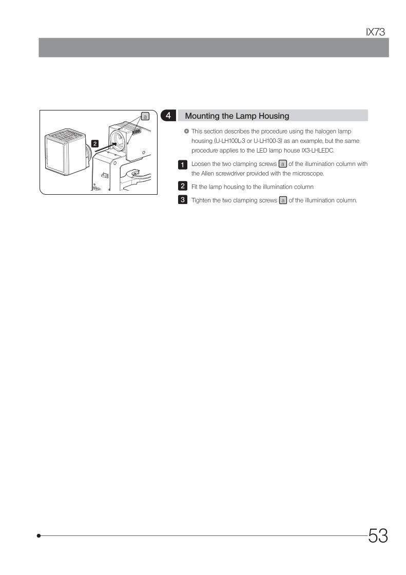
53
IX73
a
2
} This section describes the procedure using the halogen lamp
housing (U-LH100L-3 or U-LH100-3) as an example, but the same
procedure applies to the LED lamp house IX3-LHLEDC.
Loosen the two clamping screws a of the illumination column with
the Allen screwdriver provided with the microscope.
Fit the lamp housing to the illumination column
Tighten the two clamping screws a of the illumination column.
1
2
3
4 Mounting the Lamp Housing
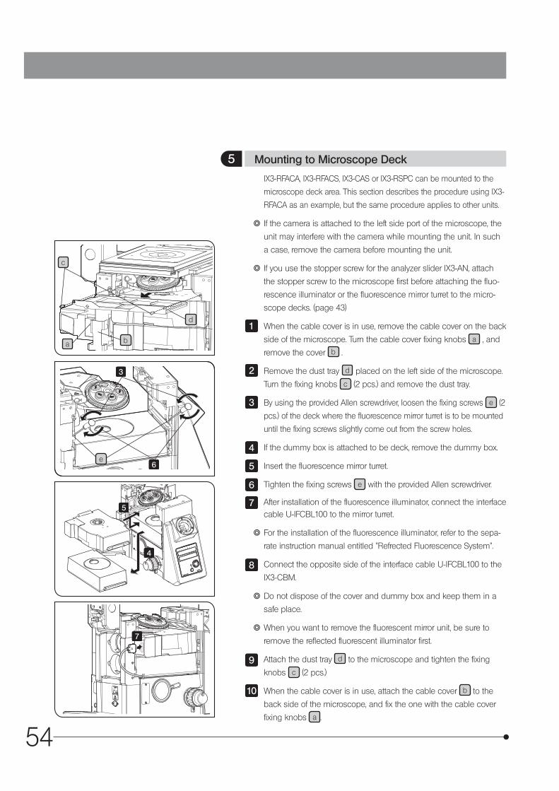
54
c
a
d
b
5 Mounting to Microscope Deck
4
5
3
6
7
IX3-RFACA, IX3-RFACS, IX3-CAS or IX3-RSPC can be mounted to the
microscope deck area. This section describes the procedure using IX3-
RFACA as an example, but the same procedure applies to other units.
} If the camera is attached to the left side port of the microscope, the
unit may interfere with the camera while mounting the unit. In such
a case, remove the camera before mounting the unit.
} If you use the stopper screw for the analyzer slider IX3-AN, attach
the stopper screw to the microscope first before attaching the fluo-
rescence illuminator or the fluorescence mirror turret to the micro-
scope decks. (page 43)
When the cable cover is in use, remove the cable cover on the back
side of the microscope. Turn the cable cover fixing knobs a , and
remove the cover b .
Remove the dust tray d placed on the left side of the microscope.
Turn the fixing knobs c (2 pcs.) and remove the dust tray.
By using the provided Allen screwdriver, loosen the fixing screws e (2
pcs.) of the deck where the fluorescence mirror turret is to be mounted
until the fixing screws slightly come out from the screw holes.
If the dummy box is attached to be deck, remove the dummy box.
Insert the fluorescence mirror turret.
Tighten the fixing screws e with the provided Allen screwdriver.
After installation of the fluorescence illuminator, connect the interface cable U-IFCBL100 to the mirror turret.
} For the installation of the fluorescence illuminator, refer to the sepa-
rate instruction manual entitled "Refrected Fluorescence System".
Connect the opposite side of the interface cable U-IFCBL100 to the
IX3-CBM.
} Do not dispose of the cover and dummy box and keep them in a
safe place.
} When you want to remove the fluorescent mirror unit, be sure to
remove the reflected fluorescent illuminator first.
Attach the dust tray d to the microscope and tighten the fixing
knobs c (2 pcs.)
When the cable cover is in use, attach the cable cover b to the
back side of the microscope, and fix the one with the cable cover
fixing knobs a .
1
2
3
4
5
6
7
8
9
10
e

55
IX73
4
6
7
8
a
5
} When attaching the BX3-SSU, refer to the BX3-SSU instructions.
} The following stage mounting procedures are commonly applicable
to the IX3-SVR, IX2-SP, IX2-GS and GX-SVR.
} When mounting the mechanical stage IX-MVR, attach first the plain
stage IX2-SP in advance (see the description on the bottom of this
page).
Gently place the stage on the microscope by aligning the stage
mounting holes with the threaded holes on the frame.
Insert the four provided Allen screws into the mounting holes .
Tighten the screws using the provided Allen wrench.
} Mount the stage so that the vertical (horizontal) direction of the
stage is parallel to the vertical (horizontal) direction of the micro-
scope.
Fit the stage center plate into the stage.
The stage center plate is designed very thin so that the objec-tive will not hit it when the revolving nosepiece is rotated. Do not subject the stage center plate to impact or excessive force, as this may deform it.
} To facilitate confirmation of the objective front lens position and
application of oil for oil immersion objectives, rotate the stage center
plate so that the keyhole a will be facing the front.
Screw the stage clips IX-SCL into the threaded holes provided on
the stage top surface as needed.
} The mechanical stage with right handle IX3-SVR can be mounted
by reversing the front and rear to implement a stage with knobs on
the left position.
In this case, the movement range will be decreased and it will be
difficult to check scales.
Attaching the sample holder
Remove the holder fixing screws (4 screws) by using the Allen
wrench provided with IX3-SVR.
Remove the round stage center plate holder.
Set IX3-HOW in the center of the stage, and attach the holder fixing
screws.
If you are using IX3-HOW or IX3-HO35D, set the sample holder in
the center of IX3-HOW.
1
2
3
CAUTION
4
5
6
7
8
6 Attaching the Stage2
3
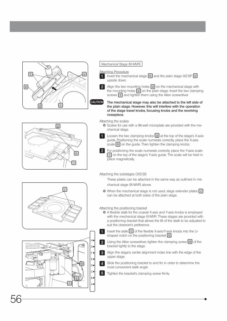
56
k
l
m
b
cd
ef
g
h
i
j
1234567
8910
1112
HG
FE
D
C
B
A
Mechanical Stage (IX-MVR)
Attaching ProcedureInvert the mechanical stage b and the plain stage IX2-SP c upside down.
Align the two mounting holes d on the mechanical stage with the mounting holes e on the plain stage. Insert the two clamping screws f and tighten them using the Allen screwdriver.
The mechanical stage may also be attached to the left side of the plain stage. However, this will interfere with the operation of the stage travel knobs, focusing knobs and the revolving nosepiece.
Attaching the scales } Scales for use with a 96-well microplate are provided with the me-chanical stage.
Loosen the two clamping knobs g at the top of the stage’s X-axis guide. Positioning the scale numerals correctly, place the X-axis scale h on the guide. Then tighten the clamping knobs.
For positioning the scale numerals correctly, place the Y-axis scale i on the top of the stage’s Y-axis guide. The scale will be held in
place magnetically.
Attaching the substages CK2-SS
These plates can be attached in the same way as outlined in me-
chanical stage (IX-MVR) above.
} When the mechanical stage is not used, stage extender plates j can be attached at both sides of the plain stage.
Attaching the positioning bracket } A flexible stalk for the coaxial X-axis and Y-axis knobs is employed with the mechanical stage IX-MVR. These stages are provided with a positioning bracket that allows the tilt of the stalk to be adjusted to suit the observer’s preference.
Insert the stalk l of the flexible X-axis/Y-axis knobs into the U-shaped notch on the positioning bracket k .
Using the Allen screwdriver, tighten the clamping screw m of the bracket lightly to the stage.
Align the stage’s center alignment index line with the edge of the upper stage.
Slide the positioning bracket to and fro in order to determine the most convenient stalk angle.
Tighten the bracket’s clamping screw firmly.
1
2
CAUTION
1
2
1
2
3
4
5
H
G
F
E
D
C
B
A
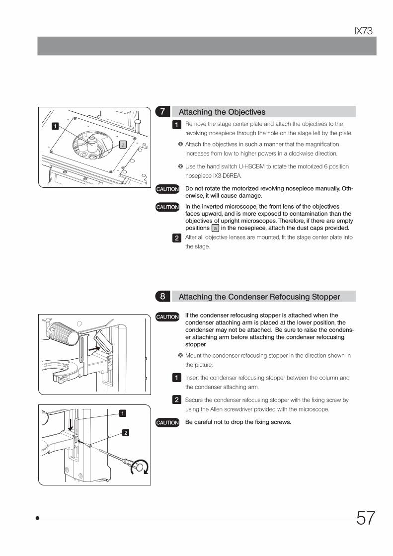
57
IX73
1
1
2
a
Remove the stage center plate and attach the objectives to the
revolving nosepiece through the hole on the stage left by the plate.
} Attach the objectives in such a manner that the magnification
increases from low to higher powers in a clockwise direction.
} Use the hand switch U-HSCBM to rotate the motorized 6 position
nosepiece IX3-D6REA.
Do not rotate the motorized revolving nosepiece manually. Oth-erwise, it will cause damage.
In the inverted microscope, the front lens of the objectives faces upward, and is more exposed to contamination than the objectives of upright microscopes. Therefore, if there are empty positions a in the nosepiece, attach the dust caps provided.
After all objective lenses are mounted, fit the stage center plate into
the stage.
1
CAUTION
CAUTION
2
If the condenser refocusing stopper is attached when the condenser attaching arm is placed at the lower position, the condenser may not be attached. Be sure to raise the condens-er attaching arm before attaching the condenser refocusing stopper.
} Mount the condenser refocusing stopper in the direction shown in
the picture.
Insert the condenser refocusing stopper between the column and
the condenser attaching arm.
Secure the condenser refocusing stopper with the fixing screw by
using the Allen screwdriver provided with the microscope.
Be careful not to drop the fixing screws.
CAUTION
1
2
CAUTION
7 Attaching the Objectives
8 Attaching the Condenser Refocusing Stopper
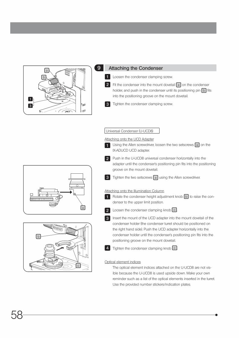
58
a
c
b
Universal Condenser (U-UCD8)
Attaching onto the UCD Adapter
Using the Allen screwdriver, loosen the two setscrews a on the
IX-ADUCD UCD adapter.
Push in the U-UCD8 universal condenser horizontally into the
adapter until the condenser’s positioning pin fits into the positioning
groove on the mount dovetail.
Tighten the two setscrews a using the Allen screwdriver.
Attaching onto the Illumination Column
Rotate the condenser height adjustment knob b to raise the con-
denser to the upper limit position.
Loosen the condenser clamping knob c .
Insert the mount of the UCD adapter into the mount dovetail of the
condenser holder (the condenser turret should be positioned on
the right hand side). Push the UCD adapter horizontally into the
condenser holder until the condenser’s positioning pin fits into the
positioning groove on the mount dovetail.
Tighten the condenser clamping knob c .
Optical element indices
The optical element indices attached on the U-UCD8 are not vis-
ible because the U-UCD8 is used upside down. Make your own
reminder such as a list of the optical elements inserted in the turret.
Use the provided number stickers/indication plates.
1
2
3
1
2
3
4
Loosen the condenser clamping screw.
Fit the condenser into the mount dovetail a on the condenser
holder, and push in the condenser until its positioning pin b fits
into the positioning groove on the mount dovetail.
Tighten the condenser clamping screw.
1
2
3
9 Attaching the Condensera
b
1
3
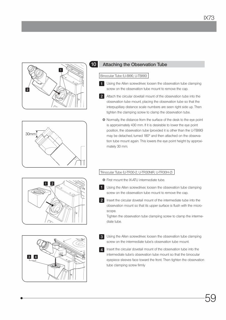
59
IX73
30mm
Binocular Tube (U-BI90, U-TBI90)
Using the Allen screwdriver, loosen the observation tube clamping
screw on the observation tube mount to remove the cap.
Attach the circular dovetail mount of the observation tube into the
observation tube mount, placing the observation tube so that the
interpupillary distance scale numbers are seen right side up. Then
tighten the clamping screw to clamp the observation tube.
} Normally, the distance from the surface of the desk to the eye point
is approximately 430 mm. If it is desirable to lower the eye point
position, the observation tube (provided it is other than the U-TBI90)
may be detached, turned 180° and then attached on the observa-
tion tube mount again. This lowers the eye point height by approxi-
mately 30 mm.
1
2
Trinocular Tube (U-TR30-2, U-TR30NIR, U-TR30H-2)
} First mount the IX-ATU intermediate tube.
Using the Allen screwdriver, loosen the observation tube clamping
screw on the observation tube mount to remove the cap.
Insert the circular dovetail mount of the intermediate tube into the
observation mount so that its upper surface is flush with the micro-
scope.
Tighten the observation tube clamping screw to clamp the interme-
diate tube.
1
2
10 Attaching the Observation Tube
Using the Allen screwdriver, loosen the observation tube clamping
screw on the intermediate tube’s observation tube mount.
Insert the circular dovetail mount of the observation tube into the
intermediate tube’s observation tube mount so that the binocular
eyepiece sleeves face toward the front. Then tighten the observation
tube clamping screw firmly
3
4
1
2
1
3
2
4
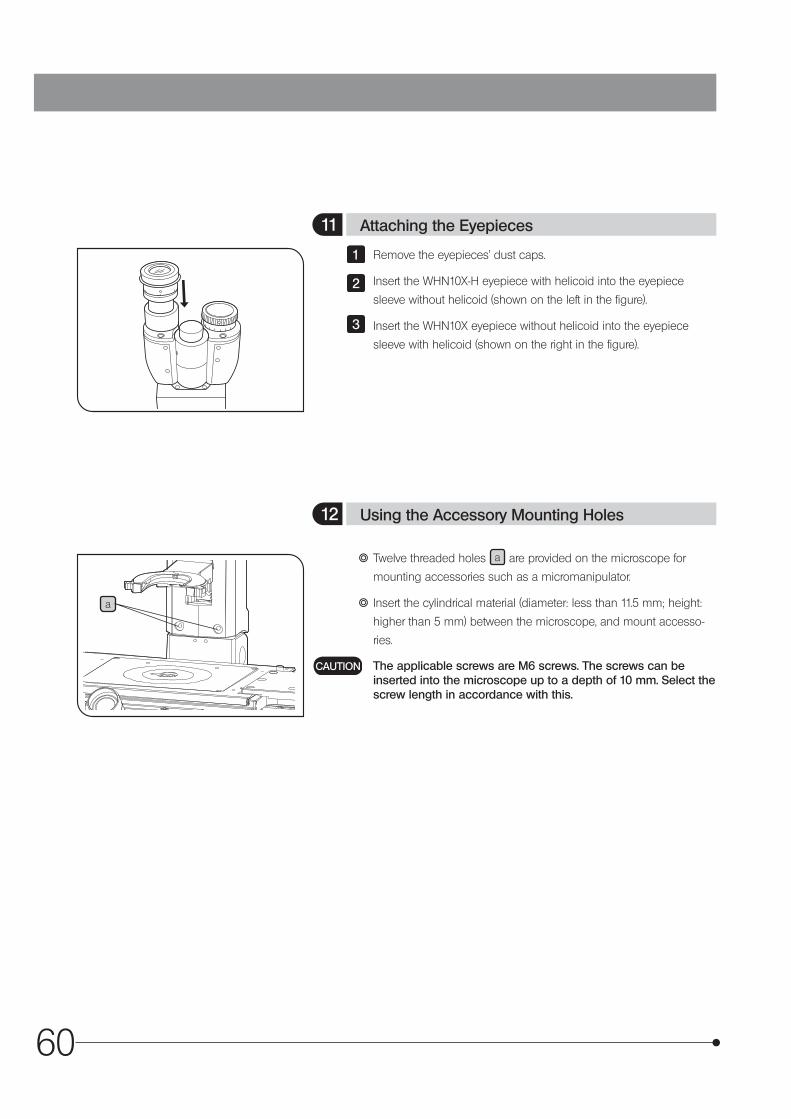
60
a
Remove the eyepieces’ dust caps.
Insert the WHN10X-H eyepiece with helicoid into the eyepiece
sleeve without helicoid (shown on the left in the figure).
Insert the WHN10X eyepiece without helicoid into the eyepiece
sleeve with helicoid (shown on the right in the figure).
1
2
3
} Twelve threaded holes a are provided on the microscope for
mounting accessories such as a micromanipulator.
} Insert the cylindrical material (diameter: less than 11.5 mm; height:
higher than 5 mm) between the microscope, and mount accesso-
ries.
The applicable screws are M6 screws. The screws can be inserted into the microscope up to a depth of 10 mm. Select the screw length in accordance with this.
CAUTION
11 Attaching the Eyepieces
12 Using the Accessory Mounting Holes
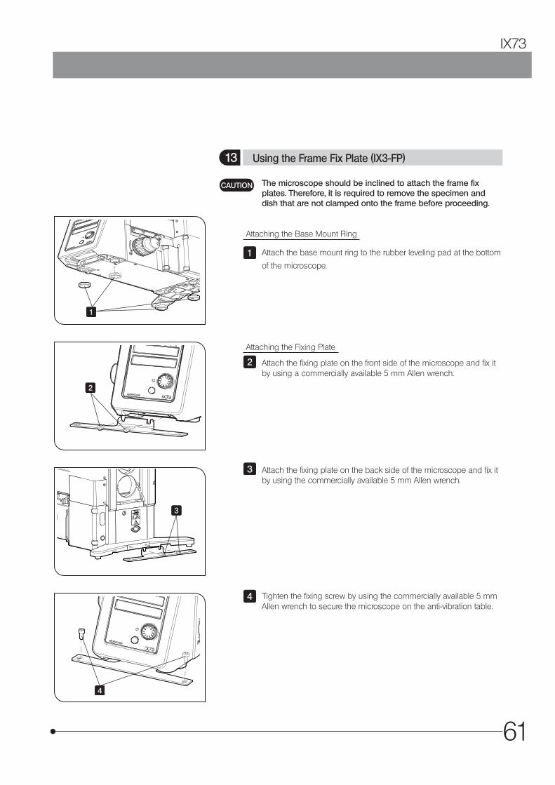
61
IX73
The microscope should be inclined to attach the frame fix plates. Therefore, it is required to remove the specimen and dish that are not clamped onto the frame before proceeding.
Attaching the Base Mount Ring
Attach the base mount ring to the rubber leveling pad at the bottom
of the microscope.
CAUTION
1
Attaching the Fixing Plate
Attach the fixing plate on the front side of the microscope and fix it by using a commercially available 5 mm Allen wrench.
2
13 Using the Frame Fix Plate (IX3-FP)
Attach the fixing plate on the back side of the microscope and fix it by using the commercially available 5 mm Allen wrench.
3
Tighten the fixing screw by using the commercially available 5 mm Allen wrench to secure the microscope on the anti-vibration table.
4
1
2
3
4
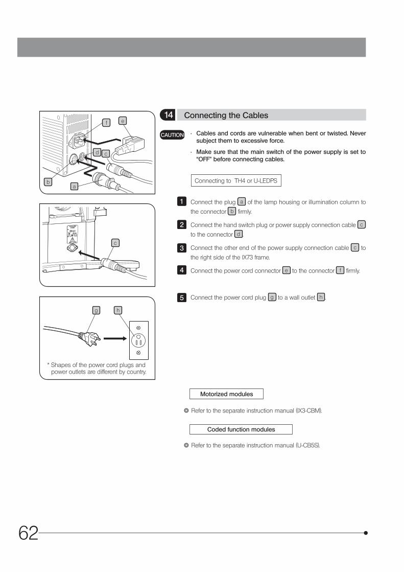
62
Connecting to TH4 or U-LEDPS
Motorized modules
Coded function modules
} Refer to the separate instruction manual (IX3-CBM).
} Refer to the separate instruction manual (U-CB5S).
c
• Cables and cords are vulnerable when bent or twisted. Never subject them to excessive force.
• Make sure that the main switch of the power supply is set to “OFF” before connecting cables.
CAUTION
14 Connecting the Cables
ba
d c
ef
Connect the plug a of the lamp housing or illumination column to
the connector b firmly.
Connect the hand switch plug or power supply connection cable c
to the connector d .
Connect the other end of the power supply connection cable c to
the right side of the IX73 frame.
Connect the power cord connector e to the connector f firmly.
Connect the power cord plug g to a wall outlet h .
1
2
3
4
5
hg
* Shapes of the power cord plugs and power outlets are different by country.
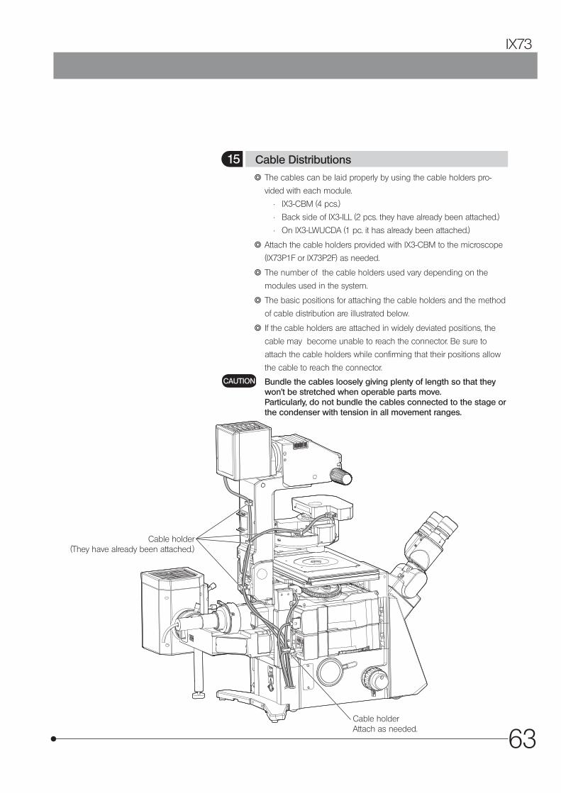
63
IX73
} The cables can be laid properly by using the cable holders pro-
vided with each module.
• IX3-CBM (4 pcs.)
• Back side of IX3-ILL (2 pcs. they have already been attached.)
• On IX3-LWUCDA (1 pc. it has already been attached.)
} Attach the cable holders provided with IX3-CBM to the microscope
(IX73P1F or IX73P2F) as needed.
} The number of the cable holders used vary depending on the
modules used in the system.
} The basic positions for attaching the cable holders and the method
of cable distribution are illustrated below.
} If the cable holders are attached in widely deviated positions, the
cable may become unable to reach the connector. Be sure to
attach the cable holders while confirming that their positions allow
the cable to reach the connector.
Bundle the cables loosely giving plenty of length so that they won’t be stretched when operable parts move. Particularly, do not bundle the cables connected to the stage or the condenser with tension in all movement ranges.
CAUTION
15 Cable Distributions
Cable holder (They have already been attached.)
Cable holder Attach as needed.
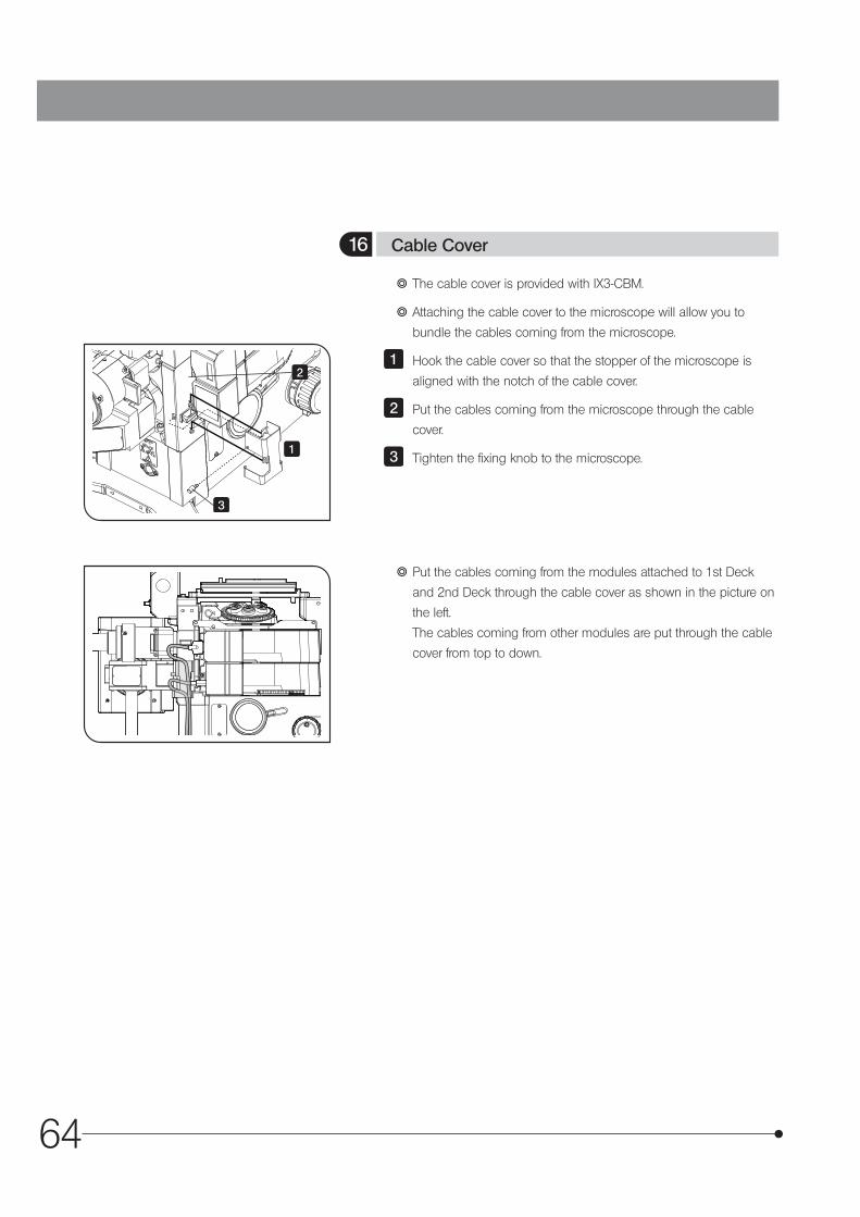
64
} The cable cover is provided with IX3-CBM.
} Attaching the cable cover to the microscope will allow you to
bundle the cables coming from the microscope.
Hook the cable cover so that the stopper of the microscope is
aligned with the notch of the cable cover.
Put the cables coming from the microscope through the cable
cover.
Tighten the fixing knob to the microscope.
} Put the cables coming from the modules attached to 1st Deck
and 2nd Deck through the cable cover as shown in the picture on
the left.
The cables coming from other modules are put through the cable
cover from top to down.
1
2
3
16 Cable Cover
1
2
3
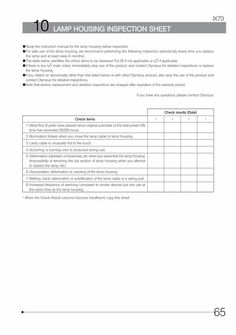
65
IX73
{ Study the instruction manual for the lamp housing before inspection.{ For safe use of the lamp housing, we recommend performing the following inspection periodically (every time you replace
the lamp and at least every 6 months).{ The table below identifies the check items to be observed. Put (X) if not applicable or ( ) if applicable.{ If there is any ( ) mark noted, immediately stop use of the product, and contact Olympus for detailed inspections or replace
the lamp housing.{ If you detect an abnormality other than that listed below or with other Olympus product, also stop the use of the product and
contact Olympus for detailed inspections.{Note that service, replacement and detailed inspections are charged after expiration of the warranty period.
If you have any questions, please contact Olympus.
Check results (Date)
Check items / / / /
1. More than 8 years have passed since original purchase or the total power ON time has exceeded 20,000 hours.
2. Illumination flickers when you move the lamp cable or lamp housing.
3. Lamp cable is unusually hot to the touch.
4. Scorching or burning odor is produced during use.
5. Deformation, backlash, or looseness, etc. when you assemble the lamp housing. (Impossibility of removing the top section of lamp housing when you attempt to replace the lamp, etc.)
6. Discoloration, deformation or cracking of the lamp housing.
7. Melting, crack, deformation or solidification of the lamp cable or a wiring part.
8. Increased frequency of servicing compared to similar devices put into use at the same time as the lamp housing.
* When the Check Result columns become insufficient, copy this sheet.
10 LAMP HOUSING INSPECTION SHEET

66
n PROPER SELECTION OF THE POWER SUPPLY CORD
If no power supply cord is provided, please select the proper power supply cord for the equipment by referring to “ Specifications ” and “ Certified Cord ” below:CAUTION: In case you use a non-approved power supply cord for Olympus products, Olympus can no longer warrant the
electrical safety of the equipment.
Specifications
Voltage RatingCurrent RatingTemperature RatingLengthFittings Configuration
125V AC (for 100-120V AC area) or, 250V AC (for 220-240V AC area)6A minimum60˚C minimum3.05 m maximumGrounding type attachment plug cap. Opposite terminates in molded-on IEC con-figuration appliance coupling.
Table 1 Certified Cord
A power supply cord should be certified by one of the agencies listed in Table 1 , or comprised of cordage marked with an agency marking per Table 1 or marked per Table 2. The fittings are to be marked with at least one of the agencies listed in Table 1. In case you are unable to buy locally in your country the power supply cord which is approved by one of the agencies mentioned in Table 1, please use replacements approved by any other equivalent and authorized agencies in your country.
Country Agency CertificationMark Country Agency Certification
Mark
Argentina IRAM Italy IMQ
Australia SAA Japan JET, JQA,
Austria ÖVE Netherlands KEMA
Belgium CEBEC Norway NEMKO
Canada CSA Spain AEE
Denmark DEMKO Sweden SEMKO
Finland FEI Switzerland SEV
France UTE United Kingdom
ASTABSI
Germany VDE U.S.A. UL
Ireland NSAI
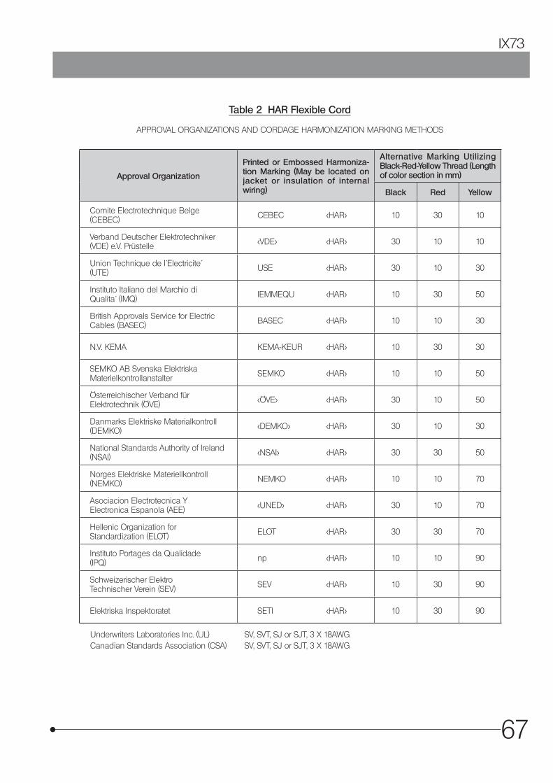
67
IX73
Table 2 HAR Flexible Cord
APPROVAL ORGANIZATIONS AND CORDAGE HARMONIZATION MARKING METHODS
Approval Organization
Printed or Embossed Harmoniza-tion Marking (May be located on jacket or insulation of internal wiring)
Alternative Marking Utilizing Black-Red-Yellow Thread (Length of color section in mm)
Black Red Yellow
Comite Electrotechnique Belge(CEBEC) CEBEC <HAR> 10 30 10
Verband Deutscher Elektrotechniker(VDE) e.V. Prüstelle <VDE> <HAR> 30 10 10
Union Technique de I´Electricite´(UTE) USE <HAR> 30 10 30
Instituto Italiano del Marchio diQualita´ (IMQ) IEMMEQU <HAR> 10 30 50
British Approvals Service for ElectricCables (BASEC) BASEC <HAR> 10 10 30
N.V. KEMA KEMA-KEUR <HAR> 10 30 30
SEMKO AB Svenska ElektriskaMaterielkontrollanstalter SEMKO <HAR> 10 10 50
Österreichischer Verband fürElektrotechnik (ÖVE) <ÖVE> <HAR> 30 10 50
Danmarks Elektriske Materialkontroll(DEMKO) <DEMKO> <HAR> 30 10 30
National Standards Authority of Ireland (NSAI) <NSAI> <HAR> 30 30 50
Norges Elektriske Materiellkontroll(NEMKO) NEMKO <HAR> 10 10 70
Asociacion Electrotecnica YElectronica Espanola (AEE) <UNED> <HAR> 30 10 70
Hellenic Organization forStandardization (ELOT) ELOT <HAR> 30 30 70
Instituto Portages da Qualidade(IPQ) np <HAR> 10 10 90
Schweizerischer ElektroTechnischer Verein (SEV) SEV <HAR> 10 30 90
Elektriska Inspektoratet SETI <HAR> 10 30 90
Underwriters Laboratories Inc. (UL) SV, SVT, SJ or SJT, 3 X 18AWG Canadian Standards Association (CSA) SV, SVT, SJ or SJT, 3 X 18AWG

68


Manufactured by
Distributed byREPEC
AX8157 01