research article influence of grain boundary on the fatigue crack growth of 7050...
TRANSCRIPT
Research ArticleInfluence of Grain Boundary on the Fatigue Crack Growth of7050-T7451 Aluminum Alloy Based on Small Time Scale Method
Weihan Wang, Weifang Zhang, Hongxun Wang, Xiaoliang Fang, and Xiaobei Liang
Science & Technology on Reliability & Environmental Engineering Laboratory, Beihang University, Beijing 100191, China
Correspondence should be addressed to Weifang Zhang; [email protected]
Received 25 March 2016; Accepted 16 June 2016
Academic Editor: Liviu Marsavina
Copyright © 2016 Weihan Wang et al. This is an open access article distributed under the Creative Commons Attribution License,which permits unrestricted use, distribution, and reproduction in any medium, provided the original work is properly cited.
Based on the small time scale method, the influence of grain boundary on the fatigue crack growth of 7050-T7451 has beeninvestigated.The interaction between fatigue crack and grain boundary was investigated by in situ SEM testing. Results showed thatthe fatigue crack growth will be retarded by grain boundary when the angle between fatigue crack and grain boundary is greaterthan 90 degrees.Mechanism analysis showed that the fatigue crack tipwould not be able to open until the loading reached the 55%ofmaximum load, and the fatigue crack had been closed completely before the loading was not reduced to the minimum value, whichled to the crack growth retardation. When the 7050-T7451 aluminum alloy suffered from fatigue loading with constant amplitude,a behavior of unstable fatigue crack growth could be observed often, and results indicated that the bridge linked mechanism led tothe behavior. The grain boundary was prone to fracture during fatigue loading, and it became the best path for the fatigue crackgrowth. The fatigue crack tip would be connected with fractured grain boundary eventually, which led to the fast crack growth indifferent loading stage.
1. Introduction
7050-T7451 is a kind of high strength aluminum alloy whichhas beenwidely used in aerospace fields for its excellent prop-erties, such as high specific strength, good fracture toughness,and stress corrosion resistance [1, 2]. Due to the fact thatthe aircraft bears complicated loadings in service, includingmaneuver loading, gust loading, and ground loading, theaccumulation of fatigue damage will appear in the structureof 7050-T7451 aluminum alloy, which may lead to the fatiguefracture and cause disastrous accidents.
In essence, the fatigue fracture of 7050-T7451 alu-minium alloy is the process of microdefect’s initiation andgrowth. Microstructure such as grain boundary and secondphase play an important role in the fatigue crack growth.Researchers found that the plastic deformation of metallicmaterials was seriously influenced by the grain boundary.Kamp et al. [3] observed that the transgranular propagationof persistent slip bands was impeded by the grain boundaryand the fatigue crack tended to grow along grain boundariesor subgrain boundaries. Scharnweber et al. [4] analyzed theeffect of grain boundary on small crack growth in stainless
steel, and results showed that the hindering effect of grainboundary on fatigue crack growth is mainly affected bythe plastic area of crack tip. Holzapfel et al. [5] foundthat the subsurface orientation of grain boundaries is animportant factor for interpreting crack growth rate at thesurface. Terentyev and Gao [6] demonstrated that both lowand high angle grain boundaries exhibit resistance to brittlecrack propagation. Wang and Dong [7] indicated that theprecipitation of carbide at grain boundary strengthened thegrain boundary and decreased the crack growth rate.
At present, the researches for the effect of grain boundaryon the fatigue crack growth aremainly focused on the fractureanalysis and in situ testing [8–10].The fracture analysis couldbe used for analyzing the damage mechanism; however, thedeformation process during the loading period is hardlyreflected and it limits the recognition of damage mechanism.The in situ testing is able to observe the whole process offatigue crack growth in real time; however, existing meth-ods mainly focused on the research of damage mechanismbetweenhundreds or thousands of loading cycles, and seldomstudies focused on the behavior of fatigue crack growthwithin one loading cycle. Recently, a method of small time
Hindawi Publishing CorporationAdvances in Materials Science and EngineeringVolume 2016, Article ID 7671530, 7 pageshttp://dx.doi.org/10.1155/2016/7671530
2 Advances in Materials Science and Engineering
8
16
10R4
4
1827
L
T 𝜙3.2 × 4
(a) (b)
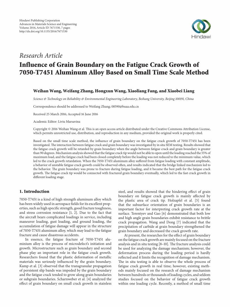
Figure 1: Geometry of the sample: (a) the sample design. (b) Manufactured sample (unit: mm).
Specimen
(a)
SEM
(b)
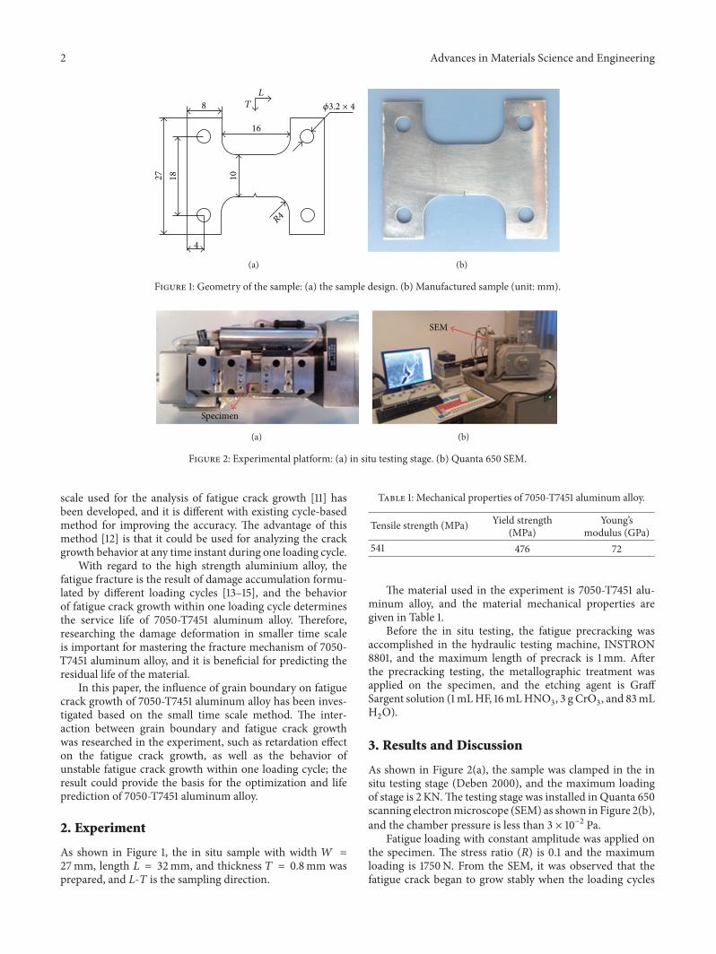
Figure 2: Experimental platform: (a) in situ testing stage. (b) Quanta 650 SEM.
scale used for the analysis of fatigue crack growth [11] hasbeen developed, and it is different with existing cycle-basedmethod for improving the accuracy. The advantage of thismethod [12] is that it could be used for analyzing the crackgrowth behavior at any time instant during one loading cycle.
With regard to the high strength aluminium alloy, thefatigue fracture is the result of damage accumulation formu-lated by different loading cycles [13–15], and the behaviorof fatigue crack growth within one loading cycle determinesthe service life of 7050-T7451 aluminum alloy. Therefore,researching the damage deformation in smaller time scaleis important for mastering the fracture mechanism of 7050-T7451 aluminum alloy, and it is beneficial for predicting theresidual life of the material.
In this paper, the influence of grain boundary on fatiguecrack growth of 7050-T7451 aluminum alloy has been inves-tigated based on the small time scale method. The inter-action between grain boundary and fatigue crack growthwas researched in the experiment, such as retardation effecton the fatigue crack growth, as well as the behavior ofunstable fatigue crack growth within one loading cycle; theresult could provide the basis for the optimization and lifeprediction of 7050-T7451 aluminum alloy.
2. Experiment
As shown in Figure 1, the in situ sample with width 𝑊 =27mm, length 𝐿 = 32mm, and thickness 𝑇 = 0.8mm wasprepared, and L-T is the sampling direction.
Table 1: Mechanical properties of 7050-T7451 aluminum alloy.
Tensile strength (MPa) Yield strength(MPa)
Young’smodulus (GPa)
541 476 72
The material used in the experiment is 7050-T7451 alu-minum alloy, and the material mechanical properties aregiven in Table 1.
Before the in situ testing, the fatigue precracking wasaccomplished in the hydraulic testing machine, INSTRON8801, and the maximum length of precrack is 1mm. Afterthe precracking testing, the metallographic treatment wasapplied on the specimen, and the etching agent is GraffSargent solution (1mLHF, 16mLHNO
3, 3 g CrO
3, and 83mL
H2O).
3. Results and Discussion
As shown in Figure 2(a), the sample was clamped in the insitu testing stage (Deben 2000), and the maximum loadingof stage is 2 KN.The testing stage was installed in Quanta 650scanning electronmicroscope (SEM) as shown in Figure 2(b),and the chamber pressure is less than 3 × 10⁻² Pa.
Fatigue loading with constant amplitude was applied onthe specimen. The stress ratio (𝑅) is 0.1 and the maximumloading is 1750N. From the SEM, it was observed that thefatigue crack began to grow stably when the loading cycles
Advances in Materials Science and Engineering 3
Crack tip
(a)
Crack tip
5.3 𝜇m
(b)
GB I
9.58 𝜇m
(c)
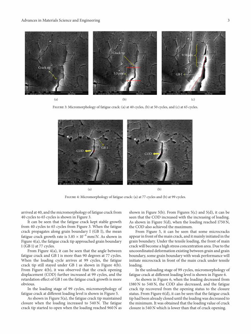
Figure 3: Micromorphology of fatigue crack: (a) at 40 cycles, (b) at 50 cycles, and (c) at 65 cycles.
GB 1 COD
(a)
COD
(b)
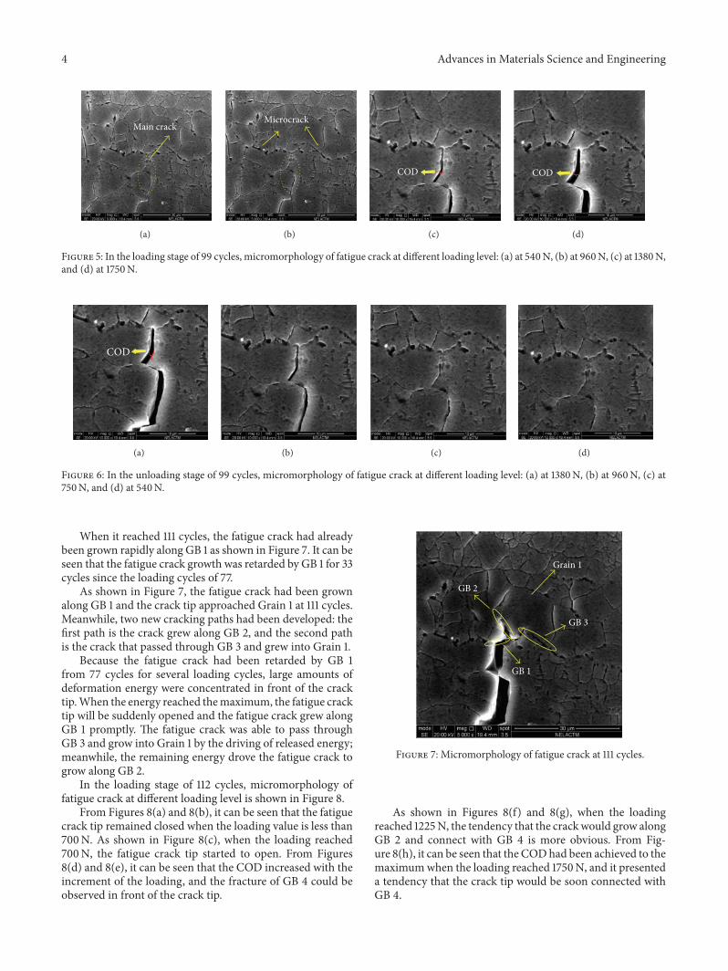
Figure 4: Micromorphology of fatigue crack: (a) at 77 cycles and (b) at 99 cycles.
arrived at 40, and themicromorphology of fatigue crack from40 cycles to 65 cycles is shown in Figure 3.
It can be seen that the fatigue crack kept stable growthfrom 40 cycles to 65 cycles from Figure 3. When the fatiguecrack propagates along grain boundary I (GB I), the meanfatigue crack growth rate is 5.85 × 10⁻⁴mm/N. As shown inFigure 4(a), the fatigue crack tip approached grain boundary1 (GB 1) at 77 cycles.
From Figure 4(a), it can be seen that the angle betweenfatigue crack and GB 1 is more than 90 degrees at 77 cycles.When the loading cycle arrives at 99 cycles, the fatiguecrack tip still stayed under GB 1 as shown in Figure 4(b).From Figure 4(b), it was observed that the crack openingdisplacement (COD) further increased at 99 cycles, and theretardation effect of GB 1 on the fatigue crack growth is moreobvious.
In the loading stage of 99 cycles, micromorphology offatigue crack at different loading level is shown in Figure 5.
As shown in Figure 5(a), the fatigue crack tip maintainedclosure when the loading increased to 540N. The fatiguecrack tip started to open when the loading reached 960N as
shown in Figure 5(b). From Figures 5(c) and 5(d), it can beseen that the COD increased with the increasing of loading.As shown in Figure 5(d), when the loading reached 1750N,the COD also achieved the maximum.
From Figure 5, it can be seen that some microcracksappear in front of themain crack, and itmainly initiated in thegrain boundary. Under the tensile loading, the front of maincrack will become a high stress concentration area. Due to theuncoordinated deformation existing between grain and grainboundary, some grain boundary with weak performance willinitiate microcrack in front of the main crack under tensileloading.
In the unloading stage of 99 cycles, micromorphology offatigue crack at different loading level is shown in Figure 6.
As shown in Figure 6, when the loading decreased from1380N to 540N, the COD also decreased, and the fatiguecrack tip recovered from the opening status to the closurestatus. From Figure 6(d), it can be seen that the fatigue cracktip had been already closed until the loading was decreased tothe minimum. It was obtained that the loading value of crackclosure is 540N which is lower than that of crack opening.
4 Advances in Materials Science and Engineering
Main crack
(a)
Microcrack
(b)
COD
(c)
COD
(d)
Figure 5: In the loading stage of 99 cycles, micromorphology of fatigue crack at different loading level: (a) at 540N, (b) at 960N, (c) at 1380N,and (d) at 1750N.
COD
(a) (b) (c) (d)
Figure 6: In the unloading stage of 99 cycles, micromorphology of fatigue crack at different loading level: (a) at 1380N, (b) at 960N, (c) at750N, and (d) at 540N.
When it reached 111 cycles, the fatigue crack had alreadybeen grown rapidly along GB 1 as shown in Figure 7. It can beseen that the fatigue crack growth was retarded by GB 1 for 33cycles since the loading cycles of 77.
As shown in Figure 7, the fatigue crack had been grownalong GB 1 and the crack tip approached Grain 1 at 111 cycles.Meanwhile, two new cracking paths had been developed: thefirst path is the crack grew along GB 2, and the second pathis the crack that passed through GB 3 and grew into Grain 1.
Because the fatigue crack had been retarded by GB 1from 77 cycles for several loading cycles, large amounts ofdeformation energy were concentrated in front of the cracktip.When the energy reached themaximum, the fatigue cracktip will be suddenly opened and the fatigue crack grew alongGB 1 promptly. The fatigue crack was able to pass throughGB 3 and grow into Grain 1 by the driving of released energy;meanwhile, the remaining energy drove the fatigue crack togrow along GB 2.
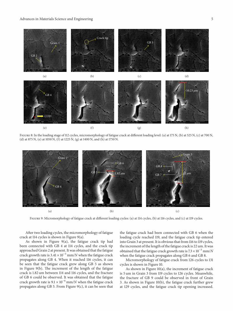
In the loading stage of 112 cycles, micromorphology offatigue crack at different loading level is shown in Figure 8.
From Figures 8(a) and 8(b), it can be seen that the fatiguecrack tip remained closed when the loading value is less than700N. As shown in Figure 8(c), when the loading reached700N, the fatigue crack tip started to open. From Figures8(d) and 8(e), it can be seen that the COD increased with theincrement of the loading, and the fracture of GB 4 could beobserved in front of the crack tip.
GB 3
Grain 1
GB 2
GB 1
Figure 7: Micromorphology of fatigue crack at 111 cycles.
As shown in Figures 8(f) and 8(g), when the loadingreached 1225N, the tendency that the crackwould grow alongGB 2 and connect with GB 4 is more obvious. From Fig-ure 8(h), it can be seen that the CODhad been achieved to themaximumwhen the loading reached 1750N, and it presenteda tendency that the crack tip would be soon connected withGB 4.
Advances in Materials Science and Engineering 5
GB 2
Grain 1
(a)
Crack tip
(b)
GB 3
(c) (d)
GB 4
COD
(e) (f) (g)
10.23 𝜇m
(h)
Figure 8: In the loading stage of 112 cycles, micromorphology of fatigue crack at different loading level: (a) at 175N, (b) at 525N, (c) at 700N,(d) at 875N, (e) at 1050N, (f) at 1225N, (g) at 1400N, and (h) at 1750N.
Grain 2
GB 4
(a)
GB 5
GB 6
1.82 𝜇m
(b)
GB 8
GB 7 22 𝜇m
Grain 3
(c)
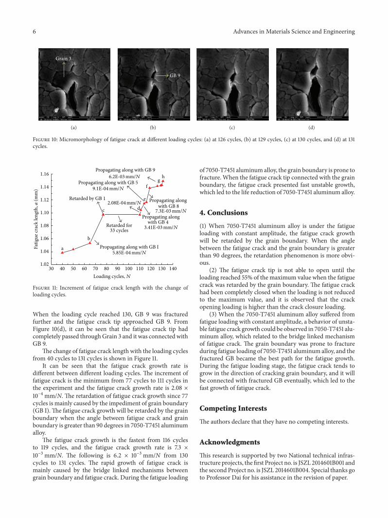
Figure 9: Micromorphology of fatigue crack at different loading cycles: (a) at 114 cycles, (b) at 116 cycles, and (c) at 119 cycles.
After two loading cycles, the micromorphology of fatiguecrack at 114 cycles is shown in Figure 9(a).
As shown in Figure 9(a), the fatigue crack tip hadbeen connected with GB 4 at 114 cycles, and the crack tipapproachedGrain 2 at present. It was obtained that the fatiguecrack growth rate is 3.41 × 10⁻³mm/N when the fatigue crackpropagates along GB 4. When it reached 116 cycles, it canbe seen that the fatigue crack grew along GB 5 as shownin Figure 9(b). The increment of the length of the fatiguecrack is 1.82 um between 114 and 116 cycles, and the fractureof GB 6 could be observed. It was obtained that the fatiguecrack growth rate is 9.1 × 10⁻⁴mm/N when the fatigue crackpropagates along GB 5. From Figure 9(c), it can be seen that
the fatigue crack had been connected with GB 6 when theloading cycle reached 119, and the fatigue crack tip enteredintoGrain 3 at present. It is obvious that from 116 to 119 cycles,the increment of the length of the fatigue crack is 22 um. Itwasobtained that the fatigue crack growth rate is 7.3 × 10⁻³mm/Nwhen the fatigue crack propagates along GB 6 and GB 8.
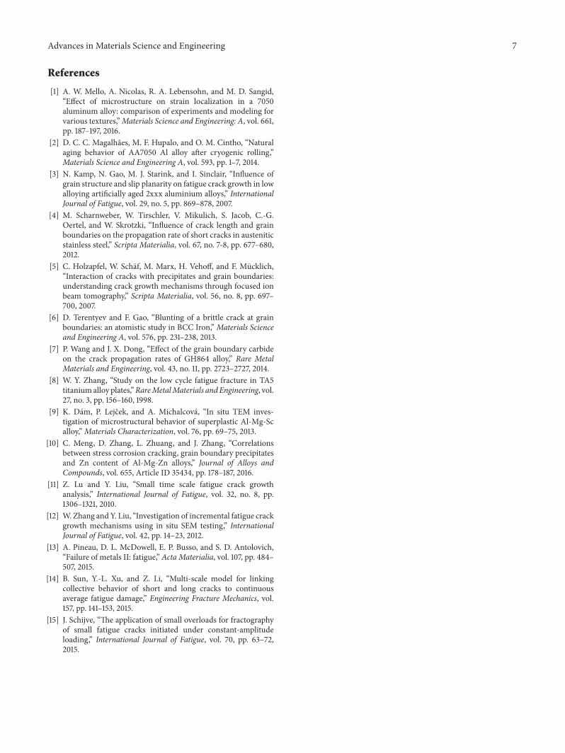
Micromorphology of fatigue crack from 126 cycles to 131cycles is shown in Figure 10.
As shown in Figure 10(a), the increment of fatigue crackis 5 um in Grain 3 from 119 cycles to 126 cycles. Meanwhile,the fracture of GB 9 could be observed in front of Grain3. As shown in Figure 10(b), the fatigue crack further grewat 129 cycles, and the fatigue crack tip opening increased.
6 Advances in Materials Science and Engineering
Grain 3
(a)
GB 9
(b) (c) (d)
Figure 10: Micromorphology of fatigue crack at different loading cycles: (a) at 126 cycles, (b) at 129 cycles, (c) at 130 cycles, and (d) at 131cycles.
30 40 50 60 70 80 90 100 110 120 130 1401.02
1.04
1.06
1.08
1.10
1.12
1.14
1.16
Propagating along with GB I
hg
f
e
dc
b
Fatig
ue cr
ack
leng
th, a
(mm
)
Loading cycles, N
a
Retarded by GB 1
Propagating alongwith GB 4
Propagating along with GB 5
Propagating alongwith GB 8
Propagating along with GB 9
Retarded for33 cycles
6.2E-03
9.1E-04
2.08E-04
5.85E-04
7.3E-03
3.41E-03
mm/N
mm/N
mm/Nmm/N
mm/N
mm/N
Figure 11: Increment of fatigue crack length with the change ofloading cycles.
When the loading cycle reached 130, GB 9 was fracturedfurther and the fatigue crack tip approached GB 9. FromFigure 10(d), it can be seen that the fatigue crack tip hadcompletely passed throughGrain 3 and it was connected withGB 9.
The change of fatigue crack length with the loading cyclesfrom 40 cycles to 131 cycles is shown in Figure 11.
It can be seen that the fatigue crack growth rate isdifferent between different loading cycles. The increment offatigue crack is the minimum from 77 cycles to 111 cycles inthe experiment and the fatigue crack growth rate is 2.08 ×10⁻⁴mm/N. The retardation of fatigue crack growth since 77cycles is mainly caused by the impediment of grain boundary(GB I).The fatigue crack growth will be retarded by the grainboundary when the angle between fatigue crack and grainboundary is greater than 90 degrees in 7050-T7451 aluminumalloy.
The fatigue crack growth is the fastest from 116 cyclesto 119 cycles, and the fatigue crack growth rate is 7.3 ×10⁻³mm/N. The following is 6.2 × 10⁻³mm/N from 130cycles to 131 cycles. The rapid growth of fatigue crack ismainly caused by the bridge linked mechanisms betweengrain boundary and fatigue crack. During the fatigue loading
of 7050-T7451 aluminum alloy, the grain boundary is prone tofracture. When the fatigue crack tip connected with the grainboundary, the fatigue crack presented fast unstable growth,which led to the life reduction of 7050-T7451 aluminum alloy.
4. Conclusions
(1) When 7050-T7451 aluminum alloy is under the fatigueloading with constant amplitude, the fatigue crack growthwill be retarded by the grain boundary. When the anglebetween the fatigue crack and the grain boundary is greaterthan 90 degrees, the retardation phenomenon is more obvi-ous.
(2) The fatigue crack tip is not able to open until theloading reached 55% of the maximum value when the fatiguecrack was retarded by the grain boundary. The fatigue crackhad been completely closed when the loading is not reducedto the maximum value, and it is observed that the crackopening loading is higher than the crack closure loading.
(3) When the 7050-T7451 aluminum alloy suffered fromfatigue loading with constant amplitude, a behavior of unsta-ble fatigue crack growth could be observed in 7050-T7451 alu-minum alloy, which related to the bridge linked mechanismof fatigue crack. The grain boundary was prone to fractureduring fatigue loading of 7050-T7451 aluminum alloy, and thefractured GB became the best path for the fatigue growth.During the fatigue loading stage, the fatigue crack tends togrow in the direction of cracking grain boundary, and it willbe connected with fractured GB eventually, which led to thefast growth of fatigue crack.
Competing Interests
The authors declare that they have no competing interests.
Acknowledgments
This research is supported by two National technical infras-tructure projects, the first Project no. is JSZL 2014601B001 andthe second Project no. is JSZL 2014601B004. Special thanks goto Professor Dai for his assistance in the revision of paper.
Advances in Materials Science and Engineering 7
References
[1] A. W. Mello, A. Nicolas, R. A. Lebensohn, and M. D. Sangid,“Effect of microstructure on strain localization in a 7050aluminum alloy: comparison of experiments and modeling forvarious textures,”Materials Science and Engineering: A, vol. 661,pp. 187–197, 2016.
[2] D. C. C. Magalhaes, M. F. Hupalo, and O. M. Cintho, “Naturalaging behavior of AA7050 Al alloy after cryogenic rolling,”Materials Science and Engineering A, vol. 593, pp. 1–7, 2014.
[3] N. Kamp, N. Gao, M. J. Starink, and I. Sinclair, “Influence ofgrain structure and slip planarity on fatigue crack growth in lowalloying artificially aged 2xxx aluminium alloys,” InternationalJournal of Fatigue, vol. 29, no. 5, pp. 869–878, 2007.
[4] M. Scharnweber, W. Tirschler, V. Mikulich, S. Jacob, C.-G.Oertel, and W. Skrotzki, “Influence of crack length and grainboundaries on the propagation rate of short cracks in austeniticstainless steel,” Scripta Materialia, vol. 67, no. 7-8, pp. 677–680,2012.
[5] C. Holzapfel, W. Schaf, M. Marx, H. Vehoff, and F. Mucklich,“Interaction of cracks with precipitates and grain boundaries:understanding crack growth mechanisms through focused ionbeam tomography,” Scripta Materialia, vol. 56, no. 8, pp. 697–700, 2007.
[6] D. Terentyev and F. Gao, “Blunting of a brittle crack at grainboundaries: an atomistic study in BCC Iron,”Materials Scienceand Engineering A, vol. 576, pp. 231–238, 2013.
[7] P. Wang and J. X. Dong, “Effect of the grain boundary carbideon the crack propagation rates of GH864 alloy,” Rare MetalMaterials and Engineering, vol. 43, no. 11, pp. 2723–2727, 2014.
[8] W. Y. Zhang, “Study on the low cycle fatigue fracture in TA5titaniumalloy plates,”RareMetalMaterials andEngineering, vol.27, no. 3, pp. 156–160, 1998.
[9] K. Dam, P. Lejcek, and A. Michalcova, “In situ TEM inves-tigation of microstructural behavior of superplastic Al-Mg-Scalloy,”Materials Characterization, vol. 76, pp. 69–75, 2013.
[10] C. Meng, D. Zhang, L. Zhuang, and J. Zhang, “Correlationsbetween stress corrosion cracking, grain boundary precipitatesand Zn content of Al-Mg-Zn alloys,” Journal of Alloys andCompounds, vol. 655, Article ID 35434, pp. 178–187, 2016.
[11] Z. Lu and Y. Liu, “Small time scale fatigue crack growthanalysis,” International Journal of Fatigue, vol. 32, no. 8, pp.1306–1321, 2010.
[12] W. Zhang and Y. Liu, “Investigation of incremental fatigue crackgrowth mechanisms using in situ SEM testing,” InternationalJournal of Fatigue, vol. 42, pp. 14–23, 2012.
[13] A. Pineau, D. L. McDowell, E. P. Busso, and S. D. Antolovich,“Failure of metals II: fatigue,” Acta Materialia, vol. 107, pp. 484–507, 2015.
[14] B. Sun, Y.-L. Xu, and Z. Li, “Multi-scale model for linkingcollective behavior of short and long cracks to continuousaverage fatigue damage,” Engineering Fracture Mechanics, vol.157, pp. 141–153, 2015.
[15] J. Schijve, “The application of small overloads for fractographyof small fatigue cracks initiated under constant-amplitudeloading,” International Journal of Fatigue, vol. 70, pp. 63–72,2015.

Submit your manuscripts athttp://www.hindawi.com
ScientificaHindawi Publishing Corporationhttp://www.hindawi.com Volume 2014
CorrosionInternational Journal of
Hindawi Publishing Corporationhttp://www.hindawi.com Volume 2014
Polymer ScienceInternational Journal of
Hindawi Publishing Corporationhttp://www.hindawi.com Volume 2014
Hindawi Publishing Corporationhttp://www.hindawi.com Volume 2014
CeramicsJournal of
Hindawi Publishing Corporationhttp://www.hindawi.com Volume 2014
CompositesJournal of
NanoparticlesJournal of
Hindawi Publishing Corporationhttp://www.hindawi.com Volume 2014
Hindawi Publishing Corporationhttp://www.hindawi.com Volume 2014
International Journal of
Biomaterials
Hindawi Publishing Corporationhttp://www.hindawi.com Volume 2014
NanoscienceJournal of
TextilesHindawi Publishing Corporation http://www.hindawi.com Volume 2014
Journal of
NanotechnologyHindawi Publishing Corporationhttp://www.hindawi.com Volume 2014
Journal of
CrystallographyJournal of
Hindawi Publishing Corporationhttp://www.hindawi.com Volume 2014
The Scientific World JournalHindawi Publishing Corporation http://www.hindawi.com Volume 2014
Hindawi Publishing Corporationhttp://www.hindawi.com Volume 2014
CoatingsJournal of
Advances in
Materials Science and EngineeringHindawi Publishing Corporationhttp://www.hindawi.com Volume 2014
Smart Materials Research
Hindawi Publishing Corporationhttp://www.hindawi.com Volume 2014
Hindawi Publishing Corporationhttp://www.hindawi.com Volume 2014
MetallurgyJournal of
Hindawi Publishing Corporationhttp://www.hindawi.com Volume 2014
BioMed Research International
MaterialsJournal of
Hindawi Publishing Corporationhttp://www.hindawi.com Volume 2014
Nano
materials
Hindawi Publishing Corporationhttp://www.hindawi.com Volume 2014
Journal ofNanomaterials