research article effect of assembly stresses on fatigue
TRANSCRIPT

Research ArticleEffect of Assembly Stresses on Fatigue Life of Symmetrical 65Si7Leaf Springs
Vinkel Kumar Arora1 Gian Bhushan2 and M L Aggarwal3
1 Department of Mechanical Engineering ITM University Sector 23A Gurgaon Haryana 122017 India2Department of Mechanical Engineering National Institute of Technology Kurukshetra Haryana 136019 India3 Department of Mechanical Engineering YMCA University of Science ampTechnology Faridabad Haryana 121006 India
Correspondence should be addressed to Vinkel Kumar Arora vinkelaroragmailcom
Received 13 March 2014 Accepted 1 May 2014 Published 4 August 2014
Academic Editor T Y Kam
Copyright copy 2014 Vinkel Kumar Arora et al This is an open access article distributed under the Creative Commons AttributionLicense which permits unrestricted use distribution and reproduction in any medium provided the original work is properlycited
Themaximum stress induced plays vital role in fatigue life improvement of leaf springs To reduce this maximum stress leaves withdifferent unassembled cambers are assembled by pulling against each other and a common curvature is established This causesstress concentration or sets assembly stress in the assembled leaf springs which is subtractive from load stress in master leaf whileit is additive to load stress for short leaves By suitable combination of assembly stresses and stepping it is possible to distributethe stress and improve the fatigue life of the leaf spring The effect of assembly stresses on fatigue life of the leaf spring of a lightcommercial vehicle (LCV) has been studied A proper combination of stepping and camber has been proposed by taking the designparameters into consideration so that the stress in the leaves does not exceed maximum design stress The theoretical fatigue lifeof the leaf springs with and without considering the assembly stresses is determined and compared with experimental life Thenumbers of specimens are manufactured with proposed parameters and tested for load rate fatigue life on a full scale leaf springstesting machine The effect of stress range maximum stress and initial stress is also discussed
1 Introduction
Leaf springs aremost frequently used in the suspensions Leafsprings like all other springs serve to absorb store and releasethe energy In heavy vehicles leaves are stacked one uponanother to ensure rigidity and strength During its operationthe leaf spring requires that the load rate should vary withinlimit (plusmn7) and themaximum stress induced should be lowerthan the maximum design stress For a given stress range theleaf spring should have maximum fatigue life or as specifiedThe stress range and the maximum stress induced in theleaf spring play a vital role in deciding the load rate andfatigue life of the leaf spring The maximum stress inducedcan be reduced by assembling the leaves with different radiiof curvature and establishing a common curvature under noload The proper distribution of the stress between the leavescan enhance the fatigue life of the leaf springs
Aggarwal et al [1] evaluated the axial fatigue strength ofEN45A spring steel specimen experimentally as a function
of shot peening in the conditions used 119878119873 curves of thespecimens were correlated with leaf springs curve in vehiclesAggarwal et al [2] concluded that the influence of highcontact pressure and temperatures resulted in microweldbetween the two leaf surfaces The fatigue strength of theleaf springs was studied as a function of shot peeningparameters Saelem et al [3] simulated a leaf springs modelAn experimental leaf springs model was verified by usinga leaf springs test rig that could measure vertical staticdeflection of leaf springs under static loading condition Theresults showed a nonlinear relationship between the appliedload and the leaf springs deflection for both directions ofloading in form of a hysteresis loop Fuentes et al [4] studiedthe origin of premature failure analysis procedures includingexamining the leaf spring history The visual inspection offractured specimens and simulation tests on real componentswere also performed It was concluded that fracture occurredby a mechanism of mechanical fatigue initiated at the regionof the central hole which suffered the highest tensile stress
Hindawi Publishing CorporationInternational Scholarly Research NoticesVolume 2014 Article ID 762561 10 pageshttpdxdoiorg1011552014762561
2 International Scholarly Research Notices
OpeningThickness
Seat lengthCentre boltDatum line
Clamp length
Fixed end Free end
Insidediameter
of eye
Width
plusmn15
plusmn6 plusmn6
Length plusmn3
Figure 1 Leaf spring assembly layout drawing [7]
levels Kumar and Vijayarangan [5] described static andfatigue analysis of steel leaf springs and composite multileafsprings made up of glass fibre reinforced polymer using lifedata analysis The dimensions of an existing conventionalsteel leaf spring of a light commercial vehicle were takenand verified by design calculations Static analysis of 2Dmodel of conventional leaf springs was also performed usingANSYS 71 and the results obtained were compared withexperimental results Patunkar and Dolas [6] worked onnonlinear force displacement of each leaf spring as well as thespring characteristics of a pack consisting of two to four leavesusing ANSYS The results from ANSYS were compared withthose from the test which showed a fairly good agreementwith each other
The objective of the present work is to determine theeffect of assembly stresses on fatigue life reliability of leafsprings It is available in open literature that with propercombination of stepping and individual leaf camber thestress distribution can be uniform along the leaf The 65Si7leaf springs design parameter of a light commercial vehicleis taken into consideration for this work This paper isdivided into two parts In part one a design procedure fordetermination of total moment of inertia number of leavesand stepping and individual leaf camber is established Thestepping and individual leaf camber is proposed with a viewto lower stresses Using SAE approach fatigue life of theleaf spring is determined theoretically by considering andnot considering the assembly stresses In part two three leafsprings specimens lots (four leaf spring assemblies in eachlot) have been manufactured All the specimens are testedon a full scale leaf spring testing machine for fatigue life ofthe leaf spring The theoretical and experimental fatigue liferesults (with and without assembly stresses) are compared forvalidationThe effect of assembly stresses and stress range onfatigue life is also depicted
2 Material
The 65Si7SUP9 grade material is used for the experimentalwork The chemical composition of the material is shown inTable 1
The mechanical properties and parameters of the 65Si7are shown in Table 2 The material is heat-treated at 880∘C
Table 1 Chemical composition of 65Si7
Grade C Si Mn S P Cr65Si7 053 020 072 0007 0019 073
and oil-quench-hardened and it is tempered at 410∘C for 90minutes to get tempered martensite structure
3 Leaf Spring Design Parameters
A leaf spring is considered as a beam of uniform strengthcomposed of leaves of equal thickness where the fiber stressis the same throughout the length of the beamThis approxi-mation is justified for most of the springs within the accuracynecessary for layout work and with certain correction factorsfor estimate of required length overhang camber widththickness and number of leaves The parameters are catego-rized as design parameters which are indicated in Table 3
4 Analytical Method for StaticAnalysis of Leaf Springs
The leaf spring assembly layout is shown in Figure 1 Thecalculation of the leaf spring parameters involves certainnumber of steps As per SAE spring design manual approachthe steps involved in leaf springs design are as follows
41 Total Moment of Inertia (Required for Desired Load Rate)Consider
sum119868 =119896 lowast 1198713
32 lowast 119864 lowast SF= 343517mm4 (1)
where 119896 = load rate 119871 = spring span 119864 = Youngrsquos modulusand SF = stiffening factor
42 Maximum Permissible Thickness for the Leaf SectionConsider
119905max =8 lowast sum 119868 lowast 119878max119871 lowast 119875max
= 820mm (2)
International Scholarly Research Notices 3
Table 2 Mechanical properties of 65Si7
Mechanicalproperty
Youngrsquosmodulus (119864) BHN Poissonrsquos ratio
(120583)Tensile strengthultimate (119878ut)
Tensile strengthyield (119878
119910
)Elongation at fracture
(minimum) Density (120588)
Value 200124MPa 380ndash432 0266 1272MPa 10812MPa 7 000000785 kgmm3
Table 3 Design parameters of the leaf springs
Span (119871) (mm) 1150 plusmn 3
Load rate (119896) (Nmm) 15911 plusmn 7Load (N)
Rated (Pg) 12959Maximum (119875max) 28010
No load camber (119862119886
) (mm) 95 plusmn 4
Seat length (mm) 100Total number of leaves (119873) 12Number of full length leaves (119883) 2Maximum thickness of the individual leaf (119905) timeswidth (119887) (mm timesmm) 8 times 70
Ride clearance (119883119888
) (mm) 946Stiffening factor (SF) 11Required fatigue life (119873
119891
) at (13 plusmn 07 g) 70000 cycles
43 Determination of Number of Leaves Consider
sum1198681= 1198731lowast 1198941 (3)
where1198731= number of leaves with thickness 119905
1 1198941=moment
of inertia for section 1199051= 8mm and width 119887 = 70mm and
1198941=1198871015840
1
lowast 1199053
1
12+31428 lowast 119905
4
1
64= 28465mm4 (4)
where 11988710158401
= 119887 minus 1199051= 62mm and119873
1= 11 Consider
sum1198681= 11 lowast 284613 = 31311mm4
sum1198682= 1198732lowast 1198942
(5)
where1198732= number of leaves with thickness 119905
2 1198942= moment
of inertia for section 1199052= 7mm and width 119887 = 70mm and
1198942=11988710158402
lowast 11990532
12+31428 lowast 1199054
2
64= 19186mm4 (6)
where1198732= 1 and 1198871015840
2
= 119887 minus 1199052= 63mm and
sum1198682= 1 lowast 19186 = 19186mm4
sum119868total = sum1198681 +sum1198682 = 33230mm4(7)
44 Modified Load Rate Consider
119870modified =sum 119868totalsum119868lowast 119896 = 15391Nmm
age variation of 119896 = 3271 (Hence acceptable) (8)
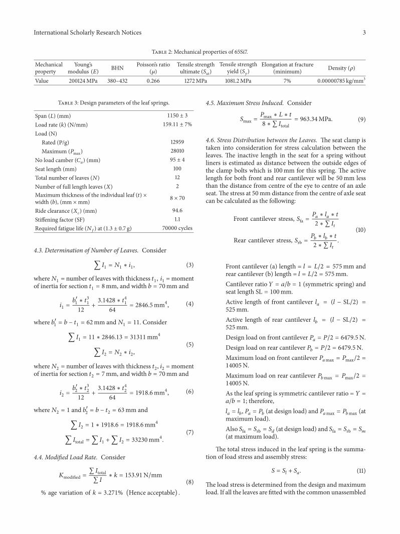
45 Maximum Stress Induced Consider
119878max =119875max lowast 119871 lowast 119905
8 lowast sum 119868total= 96334MPa (9)
46 Stress Distribution between the Leaves The seat clamp istaken into consideration for stress calculation between theleaves The inactive length in the seat for a spring withoutliners is estimated as distance between the outside edges ofthe clamp bolts which is 100mm for this spring The activelength for both front and rear cantilever will be 50mm lessthan the distance from centre of the eye to centre of an axleseat The stress at 50mm distance from the centre of axle seatcan be calculated as the following
Front cantilever stress 119878fa =119875119886lowast 119897119886lowast 119905
2 lowast sum 119868119905
Rear cantilever stress 119878rb =119875119887lowast 119897119887lowast 119905
2 lowast sum 119868119905
(10)
Front cantilever (a) length = 119897 = 1198712 = 575mm andrear cantilever (b) length = 119897 = 1198712 = 575mmCantilever ratio 119884 = 119886119887 = 1 (symmetric spring) andseat length SL = 100mmActive length of front cantilever 119897
119886= (119897 minus SL2) =
525mmActive length of rear cantilever 119897
119887= (119897 minus SL2) =
525mmDesign load on front cantilever 119875
119886= 1198752 = 64795N
Design load on rear cantilever 119875119887= 1198752 = 64795N
Maximum load on front cantilever 119875119886max = 119875max2 =
14005NMaximum load on rear cantilever 119875
119887max = 119875max2 =14005NAs the leaf spring is symmetric cantilever ratio = 119884 =119886119887 = 1 therefore119897119886= 119897119887 119875119886= 119875119887(at design load) and 119875
119886max = 119875119887max (atmaximum load)Also 119878fa = 119878rb = 119878119889 (at design load) and 119878fa = 119878rb = 119878119898(at maximum load)
The total stress induced in the leaf spring is the summa-tion of load stress and assembly stress
119878 = 119878119897+ 119878119886 (11)
The load stress is determined from the design and maximumload If all the leaves are fitted with the common unassembled
4 International Scholarly Research Notices
curvature then the assembly stress is zero but the leaves arefitted in such a manner that the radius of curvature goes onincreasing from the master leaf to the last leaf With the useof different individual leaf camber the assembly stress can beadded to or deducted from the load stress of the assembledspring to obtain desirable stress pattern in the leaf springThe assembly stress is arbitrarily chosen except they mustbe selected in increasing order from the main leaf to shorterleaf such that sum119878
1198861199052 = 0 A negative assembly stress in the
main leaf is required to reduce the maximum stress inducedin the master leaf to safe limits as the longitudinal and lateralforces are more in the master leaf A negative assembly stressis provided in the main leaf so as to reduce the maximumstress to about 866MPa The longitudinal and lateral forcesimposed on the main leaf and also its greater stress rangeare the reasons for reducing its bending stress In view of thecondition sum119878
119886sdot 1199052 = 0 several selections of deducted and
added stresses for the individual leaves are analysed beforedeciding on the best arrangement as shown in Table 4
47 Design for Individual Leaf Camber In almost all leafsprings the unassembled curvatures 119902
119899are different in the
unassembled leaves In assembly a common (unloaded)curvature 119902
119900is established which is variable along the spring
even if the leaves are made of circular arcs [8]The individualleaf curvature is calculated from common curvature as thefolowing
119902119899= 119902119900minus119878119886
119864 lowast 119910 (12)
Curvature is called positive in the direction of increasingload and camber is conventionally positive in the oppositedirection Camber can be converted into curvature as
119902119900= Curvature = minus8 lowast camber
length2= 0000574669mmminus1
(13)
The relationship between free curvature assembly curvatureand loaded curvature is given by
119902free + 119902 = 119902loaded (14)
For flat leaf the curvature is zero and it increases in thedirection of load application and for most of the springs thefree curvature is negative The no load camber requirementfor this leaf spring assembly is 95 plusmn 4mm The analyticalindividual leaf camber is shown in Table 5
48 Determination of Deflection and Bending Stress In theanalytical approach the deflection can be determined as forceper unit load rate For different values of the load the corre-sponding values of deflection can be achieved The stressesinduced at different loads can be determined by substitutingthe values of the load in the stress induced formula Theanalytical results for load deflection and bending stress areshown in Table 6
49 Fatigue Life Estimation as per SAE Spring Design ManualApproach Fatigue life is expressed by the number of deflec-tion cycles a spring will withstand without failure or perma-nent set A leaf spring used in a suspension will undergo alarge number of cycles of small amplitude near the designload position without failure Under the greater amplitudethe number of cycles without failure will be reduced since themaximumstresses aswell as the stress range are increased andboth are determining factors in fatigue life of the spring Asper SAE spring designmanual this criteria is frequently usedfor determination of approximate fatigue life of the springinitial stress (horizontal scale) and maximum stress (verticalscale) are intersected to estimate the number of cycles thespring will withstand for given loading condition
The fatigue test stroke for leaf spring without consideringassembly stress is determined as the following [8]
deflection to design load = 129591531 = 846mmmaximum load = 28KNmetal-to-metal clearance (compression stroke) =946mmtotal deflection to maximum load = 1829mmstress at metal-to-metal position = 969MPastress rate = 9691829 = 529MPammrelease stroke = 05 times 946 = 473mmfatigue test stoke = 473 + 946 = 1419mminitial stress = 969 minus (1419 times 529) = 2183MPa
The fatigue test stroke for leaf spring by consideringassembly stress is determined as the following
deflection to design load = 129591531 = 846mmmaximum load = 28KNmetal-to-metal clearance (compression stroke) =946mmtotal deflection to maximum load = 1829mmstress at metal-to-metal position = 885MPastress rate = 8851829 = 483MPammrelease stroke = 05 times 946 = 473mmfatigue test stoke = 473 + 946 = 1419mminitial stress = 885 minus (1419 times 483) = 1996MPa
5 Manufacturing of Leaf Springs
For the production of high strength leaf springs the processis comprised of shearing punching heat treatment hotcambering shot peening scragging and testing for load rateand durability The processing of the raw material plays avital role in achieving the required load rate and fatigue lifeAfter punching and shearing the raw material is moved tothe hardening furnaces for heat treatment The structure ofthe raw material is partial austenite and after quenchingthe structure is martensite but after the tempering processthe structure should be tempered martensite The material
International Scholarly Research Notices 5
Table4Stressatdesig
nload
andatmaxim
umload
byconsideringassemblystresses
Leaf
number
Thickn
ess119905
(mm)
Fron
trearc
antilever
stressa
tdesig
nload119878119889
(MPa)
Fron
trearc
antilever
stressa
tmaxim
umload119878119898
(MPa)
Assemblystr
ess
119878119886
(MPa)
Stressatdesig
nload
with
assemblystr
ess119878da(MPa)
Stressatmaxim
umload
with
assemblystr
ess119878ma
(MPa)
119878119886
sdot1199052
18
4094
888511
minus19
39048
86611
minus1216
28
4094
888511
minus15
39448
87011
minus960
38
4094
888511
minus12
3974
887311
minus768
48
4094
888511
minus10
3994
88751
1minus64
05
840
948
88511
minus8
4014
887711
minus512
68
4094
888511
minus6
40348
8791
1minus384
78
4094
888511
minus5
40448
88011
minus320
88
4094
888511
minus4
40548
88111
minus256
98
4094
888511
minus3
40648
88211
minus192
108
4094
888511
minus2
4074
888311
minus128
118
4094
888511
minus1
40848
88411
minus64
127
35830
77447
111
4693
088511
5439
Thev
arious
assemblystr
essesc
hosenprovidesum119878119886
sdot1199052=minus1w
hich
isacceptable
sum119878119886
sdot1199052=
minus1
6 International Scholarly Research Notices
Table 5 Individual leaf camber
Leafnumber 119878
119886
(MPa) 119878119886
119864 lowast 119910 119910 = 1199052 (mm) 119902119899
= 119902119900
minus 119878119886
(119864 lowast 119910)
(mmminus1) 119877119897
= 1119902119899
(mm) Individual leaf camber(119862119897
) = 119902119899
lowast 119871and
28 (mm)1 minus19 minus237353119864 minus 05 4 0000598404 1671110508 992 minus15 minus187384119864 minus 05 4 0000593408 1685182414 843 minus12 minus149907119864 minus 05 4 000058966 1695892856 804 minus10 minus124923119864 minus 05 4 0000587161 1703109109 695 minus8 minus99938119864 minus 06 4 0000584663 1710387036 566 minus6 minus749535119864 minus 06 4 0000582165 1717727431 447 minus5 minus624613119864 minus 06 4 0000580915 1721421307 348 minus4 minus49969119864 minus 06 4 0000579666 1725131104 239 minus3 minus374768119864 minus 06 4 0000578417 1728856925 1710 minus2 minus249845119864 minus 06 4 0000577168 1732598874 1111 minus1 minus124923119864 minus 06 4 0000575918 1736357057 612 111 0000158473 35 0000416196 2402714037 2
Table 6 Analytical results for load deflection and bending stress
Serial number Load type Load (N) Deflection (mm) Bending stress bytotal length (MPa)
Bending stress byactive length (MPa)
1 Unladen load 7661 503 2652 2422 Designrated load 12959 846 44848 4093 Flat load 15754 1028 5452 4984 Rubber touching load 216457 14137 74908 6845 Metal-to-metal contact 28010 1829 9692 885
is heated in the furnace in the temperature range of 880ndash910∘C depending upon the cross section thickness and widthThe spring steel is having the thickness of 8mm and widthof 70mm which is heated at 880∘C to achieve full austenitestructure Hot cambering of the spring is done in thisstate by passing through finger cambering tools followedby quenching in oil at temperature of 80∘C Tempering isdone at a temperature of 410∘C for 90min slow coolingtill the tempered martensite structure is achieved Surfacetreatment like shot peening and graphite coating is done oneach individual leaf The final assembly is done by pullingall the leaf with a centre nut and bolt The scragging of theassembly is done and the u clips are attachedThe assembly istested for load rate and fatigue life
6 Experimental Setup
The 65Si7 leaf springs assembly consists of two full lengthleaves and ten graduated leaves four rebound clips of mildsteel four shim pipes with four nut and bolts four rivetscentre nut and bolt and bush of bronze The full scale testingof leaf springs was carried out in an electrohydraulic staticcomponent testing system The laminated leaf springs wereplaced in a fixture simulating the conditions of a vehicleThe setup consists of a hydraulic power pack to give ahydraulic pressure of 206MPa with a flow rate of 210 litersper minute (lpm) which was sent to a hydraulic actuatorto operate at a frequency of 03Hz with the displacement
specified by the alternating load This involves applying theaxial load on the leaf springs and measuring the deflectionand bending stress The conventional leaf spring was testedunder static load condition by using hydraulic static loadram for load application Mounting of the leaf spring wasdone by keeping it in inverted manner on the test bed Twoeye ends were held in the clamping devices and load wasapplied from the top at the center of leaf springs To measurethe load dial indicator was used which was located besidethe full scale testing machine and deflection was measuredby strain gauges located at the clamping of the test rigThe springs were loaded from unladen load (ie 76 KN) tomaximum load (ie 28 KN) The vertical deflection of thesprings at the unladen load design load flat load rubbertouching load andmetal-to-metal contact or maximum loadwas recorded respectively as per the standard operatingprocedure prescribed [7]
The leaf springs were tested on a full scale testingmachineunder the unladen load rated load flat load rubber touchingload andmetal-to-metal load and the corresponding deflec-tion and stress values observed are shown in Table 7 Theexperiments were conducted twice and the mean value of theresults was considered Table 7 depicts the observed values ofdeflection and stress corresponding to the loads applied onthe shorter leaf by a static hydraulic ram
61 Standard for Fatigue Life Determination of Leaf SpringsAs per the IS1135 the fatigue test is conducted in deflection
International Scholarly Research Notices 7
Table 7 Experimental results for load deflection and bending stresses
Serial number Load type Load (N) Deflection (mm) Bending stress (MPa)1 Unladen load 7661 469 2622 Designrated load 12959 8144 4463 Flat load 15754 99 5404 Rubber touching load 216457 136 7435 Metal-to-metal contact 28010 176 941
0
5000
10000
15000
20000
25000
30000
0 50 100 150 200
Load
(N)
Deflection (mm)
O A B C
Figure 2 Load versus deflection for fatigue life determination
The spring shall be loaded from OA to OC as defined inFigure 2 Typically this can be between 05 times the ratedload and twice the rated load unless otherwise specified byvehicle manufacturer [7] Consider
OA = OB minus (OC minusOB)2 (15)
where OA = loaddeflection corresponding to rated loadConsider OB = loaddeflection corresponding to max-
imum load experienced under actual vehicle conditionstypically 2 g where g is the load shared by springs under theladen condition of the vehicle
Consider OC = loaddeflection corresponding to initialstress
62 Experimental Fatigue Life Determination For determi-nation of experimental fatigue life four specimens (119878-1 119878-2 119878-3 and 119878-4 per batch) for three stress ranges (ie 269ndash896MPa 218ndash969MPa and 200ndash885MPa) aremanufacturedwith proposed parameters Similar kind of material process-ing was done for all the specimens The stress range was con-sidered for first lot of the specimens to be 627MPa 13plusmn 07 gAll the four specimens were tested under same stress rangeand fatigue life was determined The stress range for secondlot of the specimen was 751MPa based on SAE spring designmanual approach without considering assembly stresses thatis all the leaves with common curvature were assembledThe stress range for third lot of the specimen was 685MPabased on SAE spring designmanual approach by consideringassembly stresses The spring was clamped in the centre tosimulate its installation in the vehicle as shown in Figure 3
As per the requirement specified by the vehicle manu-facturer the leaf springs are to be tested on full scale testing
machine as per 13 plusmn 07 gThemaximum load will be 2 g andthe minimum load will be 06 g Here g represents the designload
Consider
119878max =119875max lowast 119871119886 lowast 119905
8 lowast sum 119868total
119878min =119875min lowast 119871119886 lowast 119905
8 lowast sum 119868total
119878max =25918 lowast 1150 lowast 8
8 lowast 33230= 8969MPa
119878min =77754 lowast 1150 lowast 8
8 lowast 33230= 269MPa
(16)
7 Results and Discussion
71 Experimental Fatigue Life The experimental fatigue lifeat different stress range is shown in Table 8 The materialprocessing for all the twelve specimens is the same thatis normal rolling quenching at 880∘C tempering at 410∘Cfor 90mins shot peening at 18 A intensity BHN 380ndash432and scragging at 09 of yield stress For the first lot of thespecimens the maximum stress is 896MPa and minimumstress is 269MPa as specified by the vehiclemanufacturerThefatigue life for the four specimens is 84212 81961 82226 and85656 number of cycles The average stress life is 83513 Thesecond lot of specimen is assembled by considering commoncurvature that is without assembly stresses The maximumstress is 969MPa andminimum stress is 218MPaThe fatiguelife for the four specimens is 66796 69320 70119 and 69956number of cycles The average stress life is 69047 The thirdlot of specimens is assembled by considering the assemblystresses and leaves with proposed individual leaf camberassembled by pulling against each other to establish commoncurvature The fatigue life for the four specimens is 7482776658 79010 and 77229 number of cycles The average stresslife is 76931 It is observed that the stress range for first lotsecond lot and third lot is 627MPa 751MPa and 685MParespectively The maximum stress for first lot second lotand third lot is 896MPa 969MPa and 885MPa respectivelyIt is observed that the lower the stress range is the higherthe fatigue life will be But for almost same stress range thefatigue life decreases by increasing the maximum stress Itis also observed that the experimental fatigue life increasesby 1141 by considering assembly stresses Other factorslike shape size temperature surface and so forth also affect
8 International Scholarly Research Notices
Table 8 Experimental fatigue life of the specimens under different stress ranges
Material processing Standardspecified
Alternatingstress level(MPa)
Stressrange
Fatigue lifeof 119878-1 (119873
119891
)Fatigue lifeof 119878-2 (119873
119891
)Fatigue lifeof 119878-3 (119873
119891
)Fatigue lifeof 119878-4 (119873
119891
) Average SD
Normal rolling quenching at880∘C tempering at 410∘C for90mins shot peening at 18 Aintensity BHN 380ndash432 andscragging at 09 of yieldstress
06 gndash2 g(As specified) 269ndash896 627 84212 81961 82226 85656 Avg 83513
SD 1518
Normal rolling quenching at880∘C tempering at 410∘C for90mins shot peening at 18 Aintensity BHN 380ndash432 andscragging at 09 of yieldstress
(Without 119878119886
) 218ndash969 751 66796 69320 70119 69956 Avg 69047SD 1333
Normal rolling quenching at880∘C tempering at 410∘C for90mins shot peening at 18 Aintensity BHN 380ndash432 andscragging at 09 of yieldstress
(With 119878119886
) 200ndash885 685 74827 76658 79010 77229 Avg 76931SD 1492
Vehicle bracketCylinder actuated stroking
ForkRoller
Actuator mounting structure(height adjustable)
Figure 3 Endurance testing of symmetrical leaf springs [7]
the fatigue life of the leaf springs which can be considered forestimation of fatigue life [9]
72 Individual Leaf Camber Figure 4 shows the individualleaf camber for the leaves It is observed fromFigure 4 that theindividual leaf camber is 99mmwhich is decreasing from themain leafThe individual leaf camber is 84mm for the secondleaf with military wrapper Similarly the last leaf has individ-ual leaf camber of 2mm Hence the individual leaf camberdecreases from the main leaf to the last leaf (almost flat)
73Theoretical Fatigue LifeDetermination FromFigure 5 it isobserved that themaximum stress induced in the leaf springswithout considering the assembly stresses is 969MPa and theinitial stress value is 218MPa The intersection of 969MPaand 218MPa lies in the zone of 30000 to 50000 cycles As thepoint of intersection is nearer to 50000 cycles line therefore itwill approximately sustain around 46000 cycles
It is observed that themaximum stress induced in the leafsprings by considering the assembly stresses is 885MPa and
0102030405060708090
100
1 2 3 4 5 6 7 8 9 10 11 12
Indi
vidu
al le
af ca
mbe
r (m
m)
Leaf number
Analytical individual leaf camber
Figure 4 Analytical individual leaf camber
the initial stress value is 200MPaThe intersection of 885MPaand 200MPa lies in the zone of 50000 to 75000 cyclesAs the point of intersection is nearer to 50000 cycles line
International Scholarly Research Notices 9
Table 9 Fatigue life comparison between SAE approach and experimental result
Serial number SAE spring design manual approach age variation Experimental testing age variationFatigue life withoutassembly stress 119878
119886
Fatigue life withassembly stress 119878
119886
Fatigue life withoutassembly stress 119878
119886
Fatigue life withassembly stress 119878
119886
1 55200 69600 2608 69047 76931 1141
400
500
600
700
800
900
1000
1100
1200
1300
0 100 200 300 400 500 600 700
Max
imum
stre
ss (M
Pa)
Initial stress (MPa)
Diagram for estimating fatigue life cycles of steel leaf spring(without shot peening)
30000 cycles to failure
50000
75000
100000
200000
1000000 cycles to
Sinitial (with Sa) = 200MPa Sinitial (without Sa) = 218MPa
Smax (with Sa) = 885MPa
Smax (without Sa) = 969MPa
Figure 5Maximum versus initial stress plot (without shot peening)[8]
therefore it will approximately sustain around 58000 cyclesThe shot peening and scragging will improve the fatigue lifeby minimum of 20 Therefore fatigue life of leaf springswithout and with considering assembly stresses would beapproximately (46000 lowast 12) 55200 cycles and (58000 lowast 12)69600 cycles respectively
74 Theoretical and Experimental Fatigue Life ComparisonTable 9 shows the fatigue life comparison between the SAEspring design manual and experimental testing by consider-ing and not considering the assembly stresses It is observedfromTable 9 that as per SAE approach the fatigue life withoutconsidering the assembly stresses is 55200 cycles and byconsidering the assembly stress the fatigue life is 69600 cycles
As per SAE approach the fatigue life increases by 2608by considering assembly stress The fatigue life is 69047 and76931 cycleswithout and by considering the assembly stressesrespectively in the experimental testing In experimentaltesting it is observed that the fatigue life increases by 1141due to the reduction in stress range and maximum stress hasreduced from 969MPa to 885MPa by considering assemblystress
8 Conclusions
The theoretical and experimental fatigue life of a lightcommercial vehicle leaf spring is determined by consideringassembly stresses and without considering assembly stressesand following conclusions are made
(1) The maximum stress induced in the leaf springreduces and uniform stress distribution is achievedby considering the assembly stresses The fatigue lifeincreases due to negative assembly stresses whichreduces the maximum stress
(2) It is also concluded that for the same stress rangehigher maximum stress reduces the fatigue life ofthe leaf spring and higher initial stress improves thefatigue life of the leaf springs
Nomenclature
119862119886 No load assembly camber119862119897 Individual leaf camber119864 Youngrsquos modulus of elasticity119873119891 Number of cycles to failure119902119899 Individual leaf curvature119902119900 No load assembly curvature119877119886 No load assembly radius119877119897 Free radius for individual leaf119878119886 Assembly stress119878119889 Stress at design load without assembly stress119878da Stress at design load with assembly stressSF Stiffening factor119878fa Stress on the front cantilever119878119897 Load stress119878119898 Stress at maximum load without assembly stress119878ma Stress at maximum load with assembly stress119878rb Stress on the rear cantilever119878119905 Total stress119878ut Tensile strength ultimate119878119910 Yield strength119883119888 Ride clearance120588 Density120583 Poissonrsquos ratio
Conflict of Interests
The authors declare that there is no conflict of interestsregarding the publication of this paper
Acknowledgments
The authors would like to acknowledge Mr P S Chawlaand the leaf springs testing division of Friends Auto (India)Ltd whose unconditional support has made this projectsuccessful
10 International Scholarly Research Notices
References
[1] M L Aggarwal R A Khan andV P Agrawal ldquoOptimization ofmicro welds in leaf springs used in automotive vehiclesrdquo IndianJournal of Engineering and Materials Sciences vol 13 no 3 pp217ndash220 2006
[2] M L Aggarwal V P Agrawal and R A Khan ldquoA stressapproach model for predictions of fatigue life by shot peeningof EN45A spring steelrdquo International Journal of Fatigue vol 28no 12 pp 1845ndash1853 2006
[3] S Saelem S Chantranuwathana K Panichanun P Prem-preeda P Wichienprakarn and P Kruo-ongarjnukool ldquoExper-imental verification of leaf spring model by using a leaf springtest rigrdquo in Proceedings of the 23rd conference of MechanicalEngineering Network of Thailand November 2009
[4] J J Fuentes H J Aguilar J A Rodrıguez and E J HerreraldquoPremature fracture in automobile leaf springsrdquo EngineeringFailure Analysis vol 16 no 2 pp 648ndash665 2008
[5] M S Kumar and S Vijayarangan ldquoAnalytical and experimentalstudies on fatigue life prediction of steel and composite multi-leaf springs for light passenger vehicles using life data analysisrdquoMaterials Science vol 13 no 2 pp 141ndash146 2007
[6] M M Patunkar and D R Dolas ldquoModelling and analysisof composite leaf spring under the static load condition byusing FEArdquo International Journal of Mechanical and IndustrialEngineering vol 1 no 1 pp 1ndash4 2011
[7] IS 1135 ldquoSpringsmdashLeaf Springs Assembly for Automobilesrdquo1995
[8] Spring DesignManual ldquoDesign and application of leaf springsrdquoTech Rep HS-744 AE-11 Society of Automotive Engineers1990
[9] R L Norton Machine DesignmdashAn Integrated Approach pp366ndash383 Pearson Education Asia Hong Kong 2nd edition2001
International Journal of
AerospaceEngineeringHindawi Publishing Corporationhttpwwwhindawicom Volume 2014
RoboticsJournal of
Hindawi Publishing Corporationhttpwwwhindawicom Volume 2014
Hindawi Publishing Corporationhttpwwwhindawicom Volume 2014
Active and Passive Electronic Components
Control Scienceand Engineering
Journal of
Hindawi Publishing Corporationhttpwwwhindawicom Volume 2014
International Journal of
RotatingMachinery
Hindawi Publishing Corporationhttpwwwhindawicom Volume 2014
Hindawi Publishing Corporation httpwwwhindawicom
Journal ofEngineeringVolume 2014
Submit your manuscripts athttpwwwhindawicom
VLSI Design
Hindawi Publishing Corporationhttpwwwhindawicom Volume 2014
Hindawi Publishing Corporationhttpwwwhindawicom Volume 2014
Shock and Vibration
Hindawi Publishing Corporationhttpwwwhindawicom Volume 2014
Civil EngineeringAdvances in
Acoustics and VibrationAdvances in
Hindawi Publishing Corporationhttpwwwhindawicom Volume 2014
Hindawi Publishing Corporationhttpwwwhindawicom Volume 2014
Electrical and Computer Engineering
Journal of
Advances inOptoElectronics
Hindawi Publishing Corporation httpwwwhindawicom
Volume 2014
The Scientific World JournalHindawi Publishing Corporation httpwwwhindawicom Volume 2014
SensorsJournal of
Hindawi Publishing Corporationhttpwwwhindawicom Volume 2014
Modelling amp Simulation in EngineeringHindawi Publishing Corporation httpwwwhindawicom Volume 2014
Hindawi Publishing Corporationhttpwwwhindawicom Volume 2014
Chemical EngineeringInternational Journal of Antennas and
Propagation
International Journal of
Hindawi Publishing Corporationhttpwwwhindawicom Volume 2014
Hindawi Publishing Corporationhttpwwwhindawicom Volume 2014
Navigation and Observation
International Journal of
Hindawi Publishing Corporationhttpwwwhindawicom Volume 2014
DistributedSensor Networks
International Journal of

2 International Scholarly Research Notices
OpeningThickness
Seat lengthCentre boltDatum line
Clamp length
Fixed end Free end
Insidediameter
of eye
Width
plusmn15
plusmn6 plusmn6
Length plusmn3
Figure 1 Leaf spring assembly layout drawing [7]
levels Kumar and Vijayarangan [5] described static andfatigue analysis of steel leaf springs and composite multileafsprings made up of glass fibre reinforced polymer using lifedata analysis The dimensions of an existing conventionalsteel leaf spring of a light commercial vehicle were takenand verified by design calculations Static analysis of 2Dmodel of conventional leaf springs was also performed usingANSYS 71 and the results obtained were compared withexperimental results Patunkar and Dolas [6] worked onnonlinear force displacement of each leaf spring as well as thespring characteristics of a pack consisting of two to four leavesusing ANSYS The results from ANSYS were compared withthose from the test which showed a fairly good agreementwith each other
The objective of the present work is to determine theeffect of assembly stresses on fatigue life reliability of leafsprings It is available in open literature that with propercombination of stepping and individual leaf camber thestress distribution can be uniform along the leaf The 65Si7leaf springs design parameter of a light commercial vehicleis taken into consideration for this work This paper isdivided into two parts In part one a design procedure fordetermination of total moment of inertia number of leavesand stepping and individual leaf camber is established Thestepping and individual leaf camber is proposed with a viewto lower stresses Using SAE approach fatigue life of theleaf spring is determined theoretically by considering andnot considering the assembly stresses In part two three leafsprings specimens lots (four leaf spring assemblies in eachlot) have been manufactured All the specimens are testedon a full scale leaf spring testing machine for fatigue life ofthe leaf spring The theoretical and experimental fatigue liferesults (with and without assembly stresses) are compared forvalidationThe effect of assembly stresses and stress range onfatigue life is also depicted
2 Material
The 65Si7SUP9 grade material is used for the experimentalwork The chemical composition of the material is shown inTable 1
The mechanical properties and parameters of the 65Si7are shown in Table 2 The material is heat-treated at 880∘C
Table 1 Chemical composition of 65Si7
Grade C Si Mn S P Cr65Si7 053 020 072 0007 0019 073
and oil-quench-hardened and it is tempered at 410∘C for 90minutes to get tempered martensite structure
3 Leaf Spring Design Parameters
A leaf spring is considered as a beam of uniform strengthcomposed of leaves of equal thickness where the fiber stressis the same throughout the length of the beamThis approxi-mation is justified for most of the springs within the accuracynecessary for layout work and with certain correction factorsfor estimate of required length overhang camber widththickness and number of leaves The parameters are catego-rized as design parameters which are indicated in Table 3
4 Analytical Method for StaticAnalysis of Leaf Springs
The leaf spring assembly layout is shown in Figure 1 Thecalculation of the leaf spring parameters involves certainnumber of steps As per SAE spring design manual approachthe steps involved in leaf springs design are as follows
41 Total Moment of Inertia (Required for Desired Load Rate)Consider
sum119868 =119896 lowast 1198713
32 lowast 119864 lowast SF= 343517mm4 (1)
where 119896 = load rate 119871 = spring span 119864 = Youngrsquos modulusand SF = stiffening factor
42 Maximum Permissible Thickness for the Leaf SectionConsider
119905max =8 lowast sum 119868 lowast 119878max119871 lowast 119875max
= 820mm (2)
International Scholarly Research Notices 3
Table 2 Mechanical properties of 65Si7
Mechanicalproperty
Youngrsquosmodulus (119864) BHN Poissonrsquos ratio
(120583)Tensile strengthultimate (119878ut)
Tensile strengthyield (119878
119910
)Elongation at fracture
(minimum) Density (120588)
Value 200124MPa 380ndash432 0266 1272MPa 10812MPa 7 000000785 kgmm3
Table 3 Design parameters of the leaf springs
Span (119871) (mm) 1150 plusmn 3
Load rate (119896) (Nmm) 15911 plusmn 7Load (N)
Rated (Pg) 12959Maximum (119875max) 28010
No load camber (119862119886
) (mm) 95 plusmn 4
Seat length (mm) 100Total number of leaves (119873) 12Number of full length leaves (119883) 2Maximum thickness of the individual leaf (119905) timeswidth (119887) (mm timesmm) 8 times 70
Ride clearance (119883119888
) (mm) 946Stiffening factor (SF) 11Required fatigue life (119873
119891
) at (13 plusmn 07 g) 70000 cycles
43 Determination of Number of Leaves Consider
sum1198681= 1198731lowast 1198941 (3)
where1198731= number of leaves with thickness 119905
1 1198941=moment
of inertia for section 1199051= 8mm and width 119887 = 70mm and
1198941=1198871015840
1
lowast 1199053
1
12+31428 lowast 119905
4
1
64= 28465mm4 (4)
where 11988710158401
= 119887 minus 1199051= 62mm and119873
1= 11 Consider
sum1198681= 11 lowast 284613 = 31311mm4
sum1198682= 1198732lowast 1198942
(5)
where1198732= number of leaves with thickness 119905
2 1198942= moment
of inertia for section 1199052= 7mm and width 119887 = 70mm and
1198942=11988710158402
lowast 11990532
12+31428 lowast 1199054
2
64= 19186mm4 (6)
where1198732= 1 and 1198871015840
2
= 119887 minus 1199052= 63mm and
sum1198682= 1 lowast 19186 = 19186mm4
sum119868total = sum1198681 +sum1198682 = 33230mm4(7)
44 Modified Load Rate Consider
119870modified =sum 119868totalsum119868lowast 119896 = 15391Nmm
age variation of 119896 = 3271 (Hence acceptable) (8)
45 Maximum Stress Induced Consider
119878max =119875max lowast 119871 lowast 119905
8 lowast sum 119868total= 96334MPa (9)
46 Stress Distribution between the Leaves The seat clamp istaken into consideration for stress calculation between theleaves The inactive length in the seat for a spring withoutliners is estimated as distance between the outside edges ofthe clamp bolts which is 100mm for this spring The activelength for both front and rear cantilever will be 50mm lessthan the distance from centre of the eye to centre of an axleseat The stress at 50mm distance from the centre of axle seatcan be calculated as the following
Front cantilever stress 119878fa =119875119886lowast 119897119886lowast 119905
2 lowast sum 119868119905
Rear cantilever stress 119878rb =119875119887lowast 119897119887lowast 119905
2 lowast sum 119868119905
(10)
Front cantilever (a) length = 119897 = 1198712 = 575mm andrear cantilever (b) length = 119897 = 1198712 = 575mmCantilever ratio 119884 = 119886119887 = 1 (symmetric spring) andseat length SL = 100mmActive length of front cantilever 119897
119886= (119897 minus SL2) =
525mmActive length of rear cantilever 119897
119887= (119897 minus SL2) =
525mmDesign load on front cantilever 119875
119886= 1198752 = 64795N
Design load on rear cantilever 119875119887= 1198752 = 64795N
Maximum load on front cantilever 119875119886max = 119875max2 =
14005NMaximum load on rear cantilever 119875
119887max = 119875max2 =14005NAs the leaf spring is symmetric cantilever ratio = 119884 =119886119887 = 1 therefore119897119886= 119897119887 119875119886= 119875119887(at design load) and 119875
119886max = 119875119887max (atmaximum load)Also 119878fa = 119878rb = 119878119889 (at design load) and 119878fa = 119878rb = 119878119898(at maximum load)
The total stress induced in the leaf spring is the summa-tion of load stress and assembly stress
119878 = 119878119897+ 119878119886 (11)
The load stress is determined from the design and maximumload If all the leaves are fitted with the common unassembled
4 International Scholarly Research Notices
curvature then the assembly stress is zero but the leaves arefitted in such a manner that the radius of curvature goes onincreasing from the master leaf to the last leaf With the useof different individual leaf camber the assembly stress can beadded to or deducted from the load stress of the assembledspring to obtain desirable stress pattern in the leaf springThe assembly stress is arbitrarily chosen except they mustbe selected in increasing order from the main leaf to shorterleaf such that sum119878
1198861199052 = 0 A negative assembly stress in the
main leaf is required to reduce the maximum stress inducedin the master leaf to safe limits as the longitudinal and lateralforces are more in the master leaf A negative assembly stressis provided in the main leaf so as to reduce the maximumstress to about 866MPa The longitudinal and lateral forcesimposed on the main leaf and also its greater stress rangeare the reasons for reducing its bending stress In view of thecondition sum119878
119886sdot 1199052 = 0 several selections of deducted and
added stresses for the individual leaves are analysed beforedeciding on the best arrangement as shown in Table 4
47 Design for Individual Leaf Camber In almost all leafsprings the unassembled curvatures 119902
119899are different in the
unassembled leaves In assembly a common (unloaded)curvature 119902
119900is established which is variable along the spring
even if the leaves are made of circular arcs [8]The individualleaf curvature is calculated from common curvature as thefolowing
119902119899= 119902119900minus119878119886
119864 lowast 119910 (12)
Curvature is called positive in the direction of increasingload and camber is conventionally positive in the oppositedirection Camber can be converted into curvature as
119902119900= Curvature = minus8 lowast camber
length2= 0000574669mmminus1
(13)
The relationship between free curvature assembly curvatureand loaded curvature is given by
119902free + 119902 = 119902loaded (14)
For flat leaf the curvature is zero and it increases in thedirection of load application and for most of the springs thefree curvature is negative The no load camber requirementfor this leaf spring assembly is 95 plusmn 4mm The analyticalindividual leaf camber is shown in Table 5
48 Determination of Deflection and Bending Stress In theanalytical approach the deflection can be determined as forceper unit load rate For different values of the load the corre-sponding values of deflection can be achieved The stressesinduced at different loads can be determined by substitutingthe values of the load in the stress induced formula Theanalytical results for load deflection and bending stress areshown in Table 6
49 Fatigue Life Estimation as per SAE Spring Design ManualApproach Fatigue life is expressed by the number of deflec-tion cycles a spring will withstand without failure or perma-nent set A leaf spring used in a suspension will undergo alarge number of cycles of small amplitude near the designload position without failure Under the greater amplitudethe number of cycles without failure will be reduced since themaximumstresses aswell as the stress range are increased andboth are determining factors in fatigue life of the spring Asper SAE spring designmanual this criteria is frequently usedfor determination of approximate fatigue life of the springinitial stress (horizontal scale) and maximum stress (verticalscale) are intersected to estimate the number of cycles thespring will withstand for given loading condition
The fatigue test stroke for leaf spring without consideringassembly stress is determined as the following [8]
deflection to design load = 129591531 = 846mmmaximum load = 28KNmetal-to-metal clearance (compression stroke) =946mmtotal deflection to maximum load = 1829mmstress at metal-to-metal position = 969MPastress rate = 9691829 = 529MPammrelease stroke = 05 times 946 = 473mmfatigue test stoke = 473 + 946 = 1419mminitial stress = 969 minus (1419 times 529) = 2183MPa
The fatigue test stroke for leaf spring by consideringassembly stress is determined as the following
deflection to design load = 129591531 = 846mmmaximum load = 28KNmetal-to-metal clearance (compression stroke) =946mmtotal deflection to maximum load = 1829mmstress at metal-to-metal position = 885MPastress rate = 8851829 = 483MPammrelease stroke = 05 times 946 = 473mmfatigue test stoke = 473 + 946 = 1419mminitial stress = 885 minus (1419 times 483) = 1996MPa
5 Manufacturing of Leaf Springs
For the production of high strength leaf springs the processis comprised of shearing punching heat treatment hotcambering shot peening scragging and testing for load rateand durability The processing of the raw material plays avital role in achieving the required load rate and fatigue lifeAfter punching and shearing the raw material is moved tothe hardening furnaces for heat treatment The structure ofthe raw material is partial austenite and after quenchingthe structure is martensite but after the tempering processthe structure should be tempered martensite The material
International Scholarly Research Notices 5
Table4Stressatdesig
nload
andatmaxim
umload
byconsideringassemblystresses
Leaf
number
Thickn
ess119905
(mm)
Fron
trearc
antilever
stressa
tdesig
nload119878119889
(MPa)
Fron
trearc
antilever
stressa
tmaxim
umload119878119898
(MPa)
Assemblystr
ess
119878119886
(MPa)
Stressatdesig
nload
with
assemblystr
ess119878da(MPa)
Stressatmaxim
umload
with
assemblystr
ess119878ma
(MPa)
119878119886
sdot1199052
18
4094
888511
minus19
39048
86611
minus1216
28
4094
888511
minus15
39448
87011
minus960
38
4094
888511
minus12
3974
887311
minus768
48
4094
888511
minus10
3994
88751
1minus64
05
840
948
88511
minus8
4014
887711
minus512
68
4094
888511
minus6
40348
8791
1minus384
78
4094
888511
minus5
40448
88011
minus320
88
4094
888511
minus4
40548
88111
minus256
98
4094
888511
minus3
40648
88211
minus192
108
4094
888511
minus2
4074
888311
minus128
118
4094
888511
minus1
40848
88411
minus64
127
35830
77447
111
4693
088511
5439
Thev
arious
assemblystr
essesc
hosenprovidesum119878119886
sdot1199052=minus1w
hich
isacceptable
sum119878119886
sdot1199052=
minus1
6 International Scholarly Research Notices
Table 5 Individual leaf camber
Leafnumber 119878
119886
(MPa) 119878119886
119864 lowast 119910 119910 = 1199052 (mm) 119902119899
= 119902119900
minus 119878119886
(119864 lowast 119910)
(mmminus1) 119877119897
= 1119902119899
(mm) Individual leaf camber(119862119897
) = 119902119899
lowast 119871and
28 (mm)1 minus19 minus237353119864 minus 05 4 0000598404 1671110508 992 minus15 minus187384119864 minus 05 4 0000593408 1685182414 843 minus12 minus149907119864 minus 05 4 000058966 1695892856 804 minus10 minus124923119864 minus 05 4 0000587161 1703109109 695 minus8 minus99938119864 minus 06 4 0000584663 1710387036 566 minus6 minus749535119864 minus 06 4 0000582165 1717727431 447 minus5 minus624613119864 minus 06 4 0000580915 1721421307 348 minus4 minus49969119864 minus 06 4 0000579666 1725131104 239 minus3 minus374768119864 minus 06 4 0000578417 1728856925 1710 minus2 minus249845119864 minus 06 4 0000577168 1732598874 1111 minus1 minus124923119864 minus 06 4 0000575918 1736357057 612 111 0000158473 35 0000416196 2402714037 2
Table 6 Analytical results for load deflection and bending stress
Serial number Load type Load (N) Deflection (mm) Bending stress bytotal length (MPa)
Bending stress byactive length (MPa)
1 Unladen load 7661 503 2652 2422 Designrated load 12959 846 44848 4093 Flat load 15754 1028 5452 4984 Rubber touching load 216457 14137 74908 6845 Metal-to-metal contact 28010 1829 9692 885
is heated in the furnace in the temperature range of 880ndash910∘C depending upon the cross section thickness and widthThe spring steel is having the thickness of 8mm and widthof 70mm which is heated at 880∘C to achieve full austenitestructure Hot cambering of the spring is done in thisstate by passing through finger cambering tools followedby quenching in oil at temperature of 80∘C Tempering isdone at a temperature of 410∘C for 90min slow coolingtill the tempered martensite structure is achieved Surfacetreatment like shot peening and graphite coating is done oneach individual leaf The final assembly is done by pullingall the leaf with a centre nut and bolt The scragging of theassembly is done and the u clips are attachedThe assembly istested for load rate and fatigue life
6 Experimental Setup
The 65Si7 leaf springs assembly consists of two full lengthleaves and ten graduated leaves four rebound clips of mildsteel four shim pipes with four nut and bolts four rivetscentre nut and bolt and bush of bronze The full scale testingof leaf springs was carried out in an electrohydraulic staticcomponent testing system The laminated leaf springs wereplaced in a fixture simulating the conditions of a vehicleThe setup consists of a hydraulic power pack to give ahydraulic pressure of 206MPa with a flow rate of 210 litersper minute (lpm) which was sent to a hydraulic actuatorto operate at a frequency of 03Hz with the displacement
specified by the alternating load This involves applying theaxial load on the leaf springs and measuring the deflectionand bending stress The conventional leaf spring was testedunder static load condition by using hydraulic static loadram for load application Mounting of the leaf spring wasdone by keeping it in inverted manner on the test bed Twoeye ends were held in the clamping devices and load wasapplied from the top at the center of leaf springs To measurethe load dial indicator was used which was located besidethe full scale testing machine and deflection was measuredby strain gauges located at the clamping of the test rigThe springs were loaded from unladen load (ie 76 KN) tomaximum load (ie 28 KN) The vertical deflection of thesprings at the unladen load design load flat load rubbertouching load andmetal-to-metal contact or maximum loadwas recorded respectively as per the standard operatingprocedure prescribed [7]
The leaf springs were tested on a full scale testingmachineunder the unladen load rated load flat load rubber touchingload andmetal-to-metal load and the corresponding deflec-tion and stress values observed are shown in Table 7 Theexperiments were conducted twice and the mean value of theresults was considered Table 7 depicts the observed values ofdeflection and stress corresponding to the loads applied onthe shorter leaf by a static hydraulic ram
61 Standard for Fatigue Life Determination of Leaf SpringsAs per the IS1135 the fatigue test is conducted in deflection
International Scholarly Research Notices 7
Table 7 Experimental results for load deflection and bending stresses
Serial number Load type Load (N) Deflection (mm) Bending stress (MPa)1 Unladen load 7661 469 2622 Designrated load 12959 8144 4463 Flat load 15754 99 5404 Rubber touching load 216457 136 7435 Metal-to-metal contact 28010 176 941
0
5000
10000
15000
20000
25000
30000
0 50 100 150 200
Load
(N)
Deflection (mm)
O A B C
Figure 2 Load versus deflection for fatigue life determination
The spring shall be loaded from OA to OC as defined inFigure 2 Typically this can be between 05 times the ratedload and twice the rated load unless otherwise specified byvehicle manufacturer [7] Consider
OA = OB minus (OC minusOB)2 (15)
where OA = loaddeflection corresponding to rated loadConsider OB = loaddeflection corresponding to max-
imum load experienced under actual vehicle conditionstypically 2 g where g is the load shared by springs under theladen condition of the vehicle
Consider OC = loaddeflection corresponding to initialstress
62 Experimental Fatigue Life Determination For determi-nation of experimental fatigue life four specimens (119878-1 119878-2 119878-3 and 119878-4 per batch) for three stress ranges (ie 269ndash896MPa 218ndash969MPa and 200ndash885MPa) aremanufacturedwith proposed parameters Similar kind of material process-ing was done for all the specimens The stress range was con-sidered for first lot of the specimens to be 627MPa 13plusmn 07 gAll the four specimens were tested under same stress rangeand fatigue life was determined The stress range for secondlot of the specimen was 751MPa based on SAE spring designmanual approach without considering assembly stresses thatis all the leaves with common curvature were assembledThe stress range for third lot of the specimen was 685MPabased on SAE spring designmanual approach by consideringassembly stresses The spring was clamped in the centre tosimulate its installation in the vehicle as shown in Figure 3
As per the requirement specified by the vehicle manu-facturer the leaf springs are to be tested on full scale testing
machine as per 13 plusmn 07 gThemaximum load will be 2 g andthe minimum load will be 06 g Here g represents the designload
Consider
119878max =119875max lowast 119871119886 lowast 119905
8 lowast sum 119868total
119878min =119875min lowast 119871119886 lowast 119905
8 lowast sum 119868total
119878max =25918 lowast 1150 lowast 8
8 lowast 33230= 8969MPa
119878min =77754 lowast 1150 lowast 8
8 lowast 33230= 269MPa
(16)
7 Results and Discussion
71 Experimental Fatigue Life The experimental fatigue lifeat different stress range is shown in Table 8 The materialprocessing for all the twelve specimens is the same thatis normal rolling quenching at 880∘C tempering at 410∘Cfor 90mins shot peening at 18 A intensity BHN 380ndash432and scragging at 09 of yield stress For the first lot of thespecimens the maximum stress is 896MPa and minimumstress is 269MPa as specified by the vehiclemanufacturerThefatigue life for the four specimens is 84212 81961 82226 and85656 number of cycles The average stress life is 83513 Thesecond lot of specimen is assembled by considering commoncurvature that is without assembly stresses The maximumstress is 969MPa andminimum stress is 218MPaThe fatiguelife for the four specimens is 66796 69320 70119 and 69956number of cycles The average stress life is 69047 The thirdlot of specimens is assembled by considering the assemblystresses and leaves with proposed individual leaf camberassembled by pulling against each other to establish commoncurvature The fatigue life for the four specimens is 7482776658 79010 and 77229 number of cycles The average stresslife is 76931 It is observed that the stress range for first lotsecond lot and third lot is 627MPa 751MPa and 685MParespectively The maximum stress for first lot second lotand third lot is 896MPa 969MPa and 885MPa respectivelyIt is observed that the lower the stress range is the higherthe fatigue life will be But for almost same stress range thefatigue life decreases by increasing the maximum stress Itis also observed that the experimental fatigue life increasesby 1141 by considering assembly stresses Other factorslike shape size temperature surface and so forth also affect
8 International Scholarly Research Notices
Table 8 Experimental fatigue life of the specimens under different stress ranges
Material processing Standardspecified
Alternatingstress level(MPa)
Stressrange
Fatigue lifeof 119878-1 (119873
119891
)Fatigue lifeof 119878-2 (119873
119891
)Fatigue lifeof 119878-3 (119873
119891
)Fatigue lifeof 119878-4 (119873
119891
) Average SD
Normal rolling quenching at880∘C tempering at 410∘C for90mins shot peening at 18 Aintensity BHN 380ndash432 andscragging at 09 of yieldstress
06 gndash2 g(As specified) 269ndash896 627 84212 81961 82226 85656 Avg 83513
SD 1518
Normal rolling quenching at880∘C tempering at 410∘C for90mins shot peening at 18 Aintensity BHN 380ndash432 andscragging at 09 of yieldstress
(Without 119878119886
) 218ndash969 751 66796 69320 70119 69956 Avg 69047SD 1333
Normal rolling quenching at880∘C tempering at 410∘C for90mins shot peening at 18 Aintensity BHN 380ndash432 andscragging at 09 of yieldstress
(With 119878119886
) 200ndash885 685 74827 76658 79010 77229 Avg 76931SD 1492
Vehicle bracketCylinder actuated stroking
ForkRoller
Actuator mounting structure(height adjustable)
Figure 3 Endurance testing of symmetrical leaf springs [7]
the fatigue life of the leaf springs which can be considered forestimation of fatigue life [9]
72 Individual Leaf Camber Figure 4 shows the individualleaf camber for the leaves It is observed fromFigure 4 that theindividual leaf camber is 99mmwhich is decreasing from themain leafThe individual leaf camber is 84mm for the secondleaf with military wrapper Similarly the last leaf has individ-ual leaf camber of 2mm Hence the individual leaf camberdecreases from the main leaf to the last leaf (almost flat)
73Theoretical Fatigue LifeDetermination FromFigure 5 it isobserved that themaximum stress induced in the leaf springswithout considering the assembly stresses is 969MPa and theinitial stress value is 218MPa The intersection of 969MPaand 218MPa lies in the zone of 30000 to 50000 cycles As thepoint of intersection is nearer to 50000 cycles line therefore itwill approximately sustain around 46000 cycles
It is observed that themaximum stress induced in the leafsprings by considering the assembly stresses is 885MPa and
0102030405060708090
100
1 2 3 4 5 6 7 8 9 10 11 12
Indi
vidu
al le
af ca
mbe
r (m
m)
Leaf number
Analytical individual leaf camber
Figure 4 Analytical individual leaf camber
the initial stress value is 200MPaThe intersection of 885MPaand 200MPa lies in the zone of 50000 to 75000 cyclesAs the point of intersection is nearer to 50000 cycles line
International Scholarly Research Notices 9
Table 9 Fatigue life comparison between SAE approach and experimental result
Serial number SAE spring design manual approach age variation Experimental testing age variationFatigue life withoutassembly stress 119878
119886
Fatigue life withassembly stress 119878
119886
Fatigue life withoutassembly stress 119878
119886
Fatigue life withassembly stress 119878
119886
1 55200 69600 2608 69047 76931 1141
400
500
600
700
800
900
1000
1100
1200
1300
0 100 200 300 400 500 600 700
Max
imum
stre
ss (M
Pa)
Initial stress (MPa)
Diagram for estimating fatigue life cycles of steel leaf spring(without shot peening)
30000 cycles to failure
50000
75000
100000
200000
1000000 cycles to
Sinitial (with Sa) = 200MPa Sinitial (without Sa) = 218MPa
Smax (with Sa) = 885MPa
Smax (without Sa) = 969MPa
Figure 5Maximum versus initial stress plot (without shot peening)[8]
therefore it will approximately sustain around 58000 cyclesThe shot peening and scragging will improve the fatigue lifeby minimum of 20 Therefore fatigue life of leaf springswithout and with considering assembly stresses would beapproximately (46000 lowast 12) 55200 cycles and (58000 lowast 12)69600 cycles respectively
74 Theoretical and Experimental Fatigue Life ComparisonTable 9 shows the fatigue life comparison between the SAEspring design manual and experimental testing by consider-ing and not considering the assembly stresses It is observedfromTable 9 that as per SAE approach the fatigue life withoutconsidering the assembly stresses is 55200 cycles and byconsidering the assembly stress the fatigue life is 69600 cycles
As per SAE approach the fatigue life increases by 2608by considering assembly stress The fatigue life is 69047 and76931 cycleswithout and by considering the assembly stressesrespectively in the experimental testing In experimentaltesting it is observed that the fatigue life increases by 1141due to the reduction in stress range and maximum stress hasreduced from 969MPa to 885MPa by considering assemblystress
8 Conclusions
The theoretical and experimental fatigue life of a lightcommercial vehicle leaf spring is determined by consideringassembly stresses and without considering assembly stressesand following conclusions are made
(1) The maximum stress induced in the leaf springreduces and uniform stress distribution is achievedby considering the assembly stresses The fatigue lifeincreases due to negative assembly stresses whichreduces the maximum stress
(2) It is also concluded that for the same stress rangehigher maximum stress reduces the fatigue life ofthe leaf spring and higher initial stress improves thefatigue life of the leaf springs
Nomenclature
119862119886 No load assembly camber119862119897 Individual leaf camber119864 Youngrsquos modulus of elasticity119873119891 Number of cycles to failure119902119899 Individual leaf curvature119902119900 No load assembly curvature119877119886 No load assembly radius119877119897 Free radius for individual leaf119878119886 Assembly stress119878119889 Stress at design load without assembly stress119878da Stress at design load with assembly stressSF Stiffening factor119878fa Stress on the front cantilever119878119897 Load stress119878119898 Stress at maximum load without assembly stress119878ma Stress at maximum load with assembly stress119878rb Stress on the rear cantilever119878119905 Total stress119878ut Tensile strength ultimate119878119910 Yield strength119883119888 Ride clearance120588 Density120583 Poissonrsquos ratio
Conflict of Interests
The authors declare that there is no conflict of interestsregarding the publication of this paper
Acknowledgments
The authors would like to acknowledge Mr P S Chawlaand the leaf springs testing division of Friends Auto (India)Ltd whose unconditional support has made this projectsuccessful
10 International Scholarly Research Notices
References
[1] M L Aggarwal R A Khan andV P Agrawal ldquoOptimization ofmicro welds in leaf springs used in automotive vehiclesrdquo IndianJournal of Engineering and Materials Sciences vol 13 no 3 pp217ndash220 2006
[2] M L Aggarwal V P Agrawal and R A Khan ldquoA stressapproach model for predictions of fatigue life by shot peeningof EN45A spring steelrdquo International Journal of Fatigue vol 28no 12 pp 1845ndash1853 2006
[3] S Saelem S Chantranuwathana K Panichanun P Prem-preeda P Wichienprakarn and P Kruo-ongarjnukool ldquoExper-imental verification of leaf spring model by using a leaf springtest rigrdquo in Proceedings of the 23rd conference of MechanicalEngineering Network of Thailand November 2009
[4] J J Fuentes H J Aguilar J A Rodrıguez and E J HerreraldquoPremature fracture in automobile leaf springsrdquo EngineeringFailure Analysis vol 16 no 2 pp 648ndash665 2008
[5] M S Kumar and S Vijayarangan ldquoAnalytical and experimentalstudies on fatigue life prediction of steel and composite multi-leaf springs for light passenger vehicles using life data analysisrdquoMaterials Science vol 13 no 2 pp 141ndash146 2007
[6] M M Patunkar and D R Dolas ldquoModelling and analysisof composite leaf spring under the static load condition byusing FEArdquo International Journal of Mechanical and IndustrialEngineering vol 1 no 1 pp 1ndash4 2011
[7] IS 1135 ldquoSpringsmdashLeaf Springs Assembly for Automobilesrdquo1995
[8] Spring DesignManual ldquoDesign and application of leaf springsrdquoTech Rep HS-744 AE-11 Society of Automotive Engineers1990
[9] R L Norton Machine DesignmdashAn Integrated Approach pp366ndash383 Pearson Education Asia Hong Kong 2nd edition2001
International Journal of
AerospaceEngineeringHindawi Publishing Corporationhttpwwwhindawicom Volume 2014
RoboticsJournal of
Hindawi Publishing Corporationhttpwwwhindawicom Volume 2014
Hindawi Publishing Corporationhttpwwwhindawicom Volume 2014
Active and Passive Electronic Components
Control Scienceand Engineering
Journal of
Hindawi Publishing Corporationhttpwwwhindawicom Volume 2014
International Journal of
RotatingMachinery
Hindawi Publishing Corporationhttpwwwhindawicom Volume 2014
Hindawi Publishing Corporation httpwwwhindawicom
Journal ofEngineeringVolume 2014
Submit your manuscripts athttpwwwhindawicom
VLSI Design
Hindawi Publishing Corporationhttpwwwhindawicom Volume 2014
Hindawi Publishing Corporationhttpwwwhindawicom Volume 2014
Shock and Vibration
Hindawi Publishing Corporationhttpwwwhindawicom Volume 2014
Civil EngineeringAdvances in
Acoustics and VibrationAdvances in
Hindawi Publishing Corporationhttpwwwhindawicom Volume 2014
Hindawi Publishing Corporationhttpwwwhindawicom Volume 2014
Electrical and Computer Engineering
Journal of
Advances inOptoElectronics
Hindawi Publishing Corporation httpwwwhindawicom
Volume 2014
The Scientific World JournalHindawi Publishing Corporation httpwwwhindawicom Volume 2014
SensorsJournal of
Hindawi Publishing Corporationhttpwwwhindawicom Volume 2014
Modelling amp Simulation in EngineeringHindawi Publishing Corporation httpwwwhindawicom Volume 2014
Hindawi Publishing Corporationhttpwwwhindawicom Volume 2014
Chemical EngineeringInternational Journal of Antennas and
Propagation
International Journal of
Hindawi Publishing Corporationhttpwwwhindawicom Volume 2014
Hindawi Publishing Corporationhttpwwwhindawicom Volume 2014
Navigation and Observation
International Journal of
Hindawi Publishing Corporationhttpwwwhindawicom Volume 2014
DistributedSensor Networks
International Journal of

International Journal of
AerospaceEngineeringHindawi Publishing Corporationhttpwwwhindawicom Volume 2014
RoboticsJournal of
Hindawi Publishing Corporationhttpwwwhindawicom Volume 2014
Hindawi Publishing Corporationhttpwwwhindawicom Volume 2014
Active and Passive Electronic Components
Control Scienceand Engineering
Journal of
Hindawi Publishing Corporationhttpwwwhindawicom Volume 2014
International Journal of
RotatingMachinery
Hindawi Publishing Corporationhttpwwwhindawicom Volume 2014
Hindawi Publishing Corporation httpwwwhindawicom
Journal ofEngineeringVolume 2014
Submit your manuscripts athttpwwwhindawicom
VLSI Design
Hindawi Publishing Corporationhttpwwwhindawicom Volume 2014
Hindawi Publishing Corporationhttpwwwhindawicom Volume 2014
Shock and Vibration
Hindawi Publishing Corporationhttpwwwhindawicom Volume 2014
Civil EngineeringAdvances in
Acoustics and VibrationAdvances in
Hindawi Publishing Corporationhttpwwwhindawicom Volume 2014
Hindawi Publishing Corporationhttpwwwhindawicom Volume 2014
Electrical and Computer Engineering
Journal of
Advances inOptoElectronics
Hindawi Publishing Corporation httpwwwhindawicom
Volume 2014
The Scientific World JournalHindawi Publishing Corporation httpwwwhindawicom Volume 2014
SensorsJournal of
Hindawi Publishing Corporationhttpwwwhindawicom Volume 2014
Modelling amp Simulation in EngineeringHindawi Publishing Corporation httpwwwhindawicom Volume 2014
Hindawi Publishing Corporationhttpwwwhindawicom Volume 2014
Chemical EngineeringInternational Journal of Antennas and
Propagation
International Journal of
Hindawi Publishing Corporationhttpwwwhindawicom Volume 2014
Hindawi Publishing Corporationhttpwwwhindawicom Volume 2014
Navigation and Observation
International Journal of
Hindawi Publishing Corporationhttpwwwhindawicom Volume 2014
DistributedSensor Networks
International Journal of