requirements concerning pipes and pressure vessels - iacs · requirements concerning pipes and...
TRANSCRIPT
INTERNATIONAL ASSOCIATION OF CLASSIFICATION SOCIETIES
Requirements concerning
PIPES AND PRESSURE VESSELS
Page 1 IACS Req. 2016
CONTENTS P1 Rules for pipes Rev.5 Nov 2001 P2 Rules for piping design, construction and testing P2.7.4 Mechanical joints Rev.8 Mar 2016 P2.11 Type approval of mechanical joints Rev.4 Mar 2016 P2.12 Flexible hoses Rev.2 Mar 2016 P3 Air pipe closing devices Rev.4 Jan 2016 P4 Production and application of plastic pipes on ships* Rev.4 Dec 2008 P5 Ballast water systems. Requirements on ballast water exchange at sea Del Apr 2011 P6 Shell type exhaust gas heated economizers that may be isolated from the steam plant system Rev.1 June 2015 See also LL36 and Recommendation Nos. 4 and 5
P1.1 - P1.2
Rules for pipes
P1.1 Scope(1987)
This requirement is applicable to all piping systems covered by classification unless superseded by otherUR and interpretation applicable to specific piping systems.Chemical cargo and process piping are excluded from the scope of the present requirement.
P1.2 Strength of pipes(1972 Rev. 11987Rev. 21997Rev. 3May, 1998) (Rev.4, June 2000) (Rev.5, Nov.2001)
P1.2.1 Required wall thickness
The minimum wall thickness of pipes is not to be less than the greater of the values obtained by P1.2.2,P1.2.3, as applicable, or the minimum wall thickness required by P1.2.4.
P1.2.2 Calculated wall thickness
The following requirements apply for pipes where the ratio outside-diameter to inside-diameter does notexceed the value 1.7.The calculated wall thickness for straight or bent pressure pipes is not to be less than determined from thefollowing formula, as applicable:
t = t0 + b + c (1)
where t = minimum calculated thickness(mm)t0 = thickness calculated by the following basic formula (mm)
t = (2)
P = design pressure (bar) (see P1.2.7)D = outside diameter (mm)K = permissible stress (N/mm2) (from P1.2.5 and P1.2.6)e = efficiency factor
(i) e = 1 for seamless pipes and for welded pipes delivered by manufacturers approved for making welded pipes which are considered an equivalent to seamless pipes.
(ii) for other welded pipes the Classification Society will consider an efficiency factor value depending upon the service and the welding procedure.
b = allowance for bendingThe value for this allowance is to be chosen in such a way that the calculated stress in the bend, due to the internal pressure only, does not exceed the permissible stress.When this allowance is not determined by a more accurate procedure, it is to be taken as not less than:
b = t0 (3)
where R = mean radius of the bend (mm)c = corrosion allowance (mm) (from Tables 1 and 2).
P1(Rev 21997)(Rev 3May1998)(Rev.4June 2000)(Rev.5Nov. 2001)
IACS Req. 1998/Rev.5 2001
▲
▲
PD20 Ke + P
12,5
DR
P1-1
P1.2, Table 1
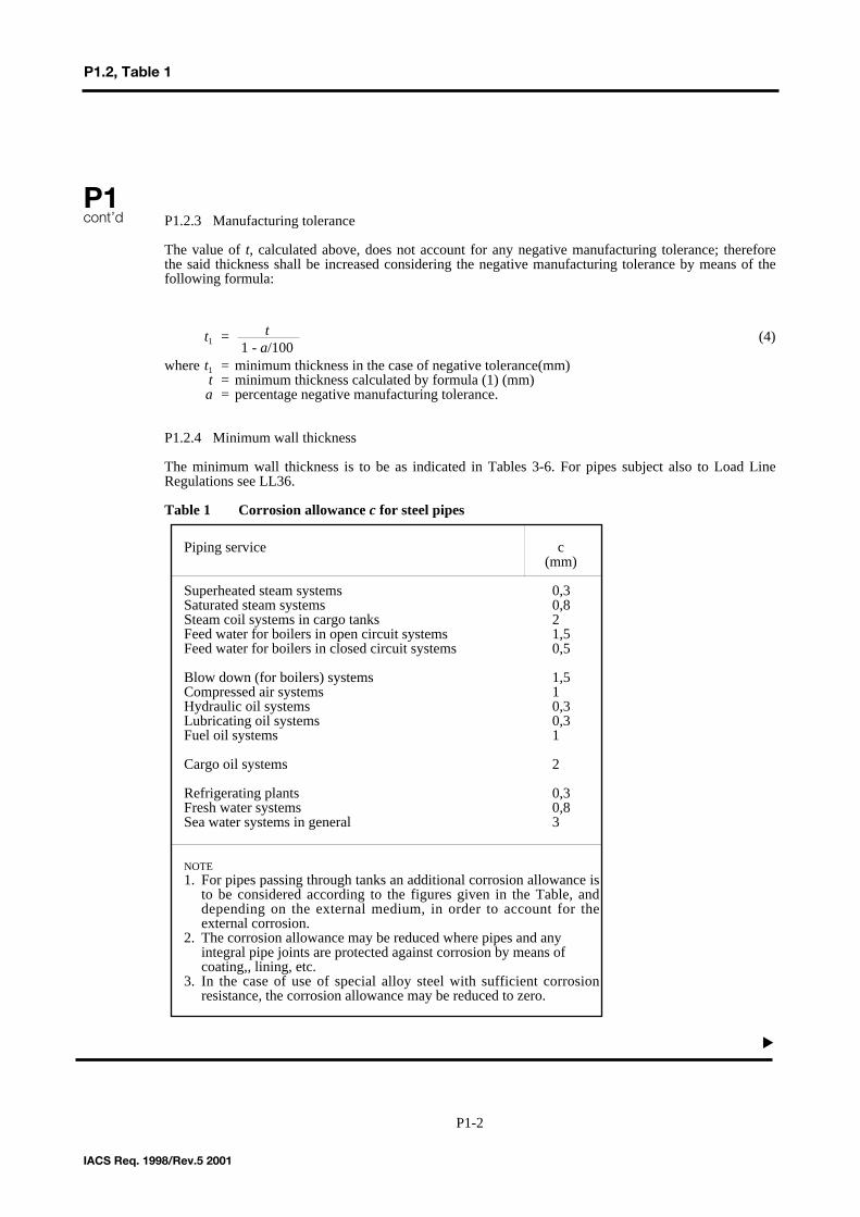
P1.2.3 Manufacturing tolerance
The value of t, calculated above, does not account for any negative manufacturing tolerance; thereforethe said thickness shall be increased considering the negative manufacturing tolerance by means of thefollowing formula:
t1 = (4)
where t1 = minimum thickness in the case of negative tolerance(mm)t = minimum thickness calculated by formula (1) (mm)a = percentage negative manufacturing tolerance.
P1.2.4 Minimum wall thickness
The minimum wall thickness is to be as indicated in Tables 3-6. For pipes subject also to Load LineRegulations see LL36.
Table 1 Corrosion allowance c for steel pipes
P1cont’d
IACS Req. 1998/Rev.5 2001
▲
t1 - a/100
P1-2
Piping service c(mm)
Superheated steam systems 0,3Saturated steam systems 0,8Steam coil systems in cargo tanks 2Feed water for boilers in open circuit systems 1,5Feed water for boilers in closed circuit systems 0,5
Blow down (for boilers) systems 1,5Compressed air systems 1Hydraulic oil systems 0,3Lubricating oil systems 0,3Fuel oil systems 1
Cargo oil systems 2
Refrigerating plants 0,3Fresh water systems 0,8Sea water systems in general 3
NOTE1. For pipes passing through tanks an additional corrosion allowance is
to be considered according to the figures given in the Table, and depending on the external medium, in order to account for the external corrosion.
2. The corrosion allowance may be reduced where pipes and any integral pipe joints are protected against corrosion by means of coating,, lining, etc.
3. In the case of use of special alloy steel with sufficient corrosion resistance, the corrosion allowance may be reduced to zero.
P1.2, Table 2
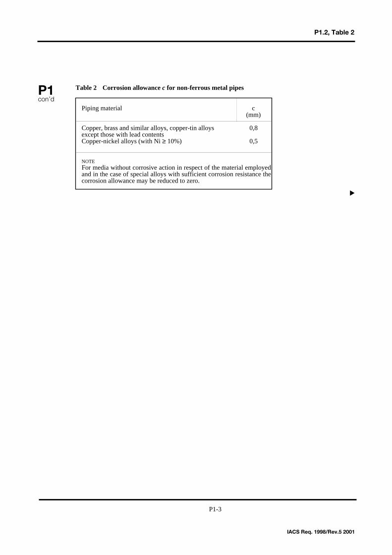
Table 2 Corrosion allowance c for non-ferrous metal pipesP1con’d
IACS Req. 1998/Rev.5 2001
▲
Piping material c(mm)
Copper, brass and similar alloys, copper-tin alloys 0,8except those with lead contentsCopper-nickel alloys (with Ni ≥ 10%) 0,5
NOTEFor media without corrosive action in respect of the material employed and in the case of special alloys with sufficient corrosion resistance the corrosion allowance may be reduced to zero.
P1-3
P1.2, Table 3
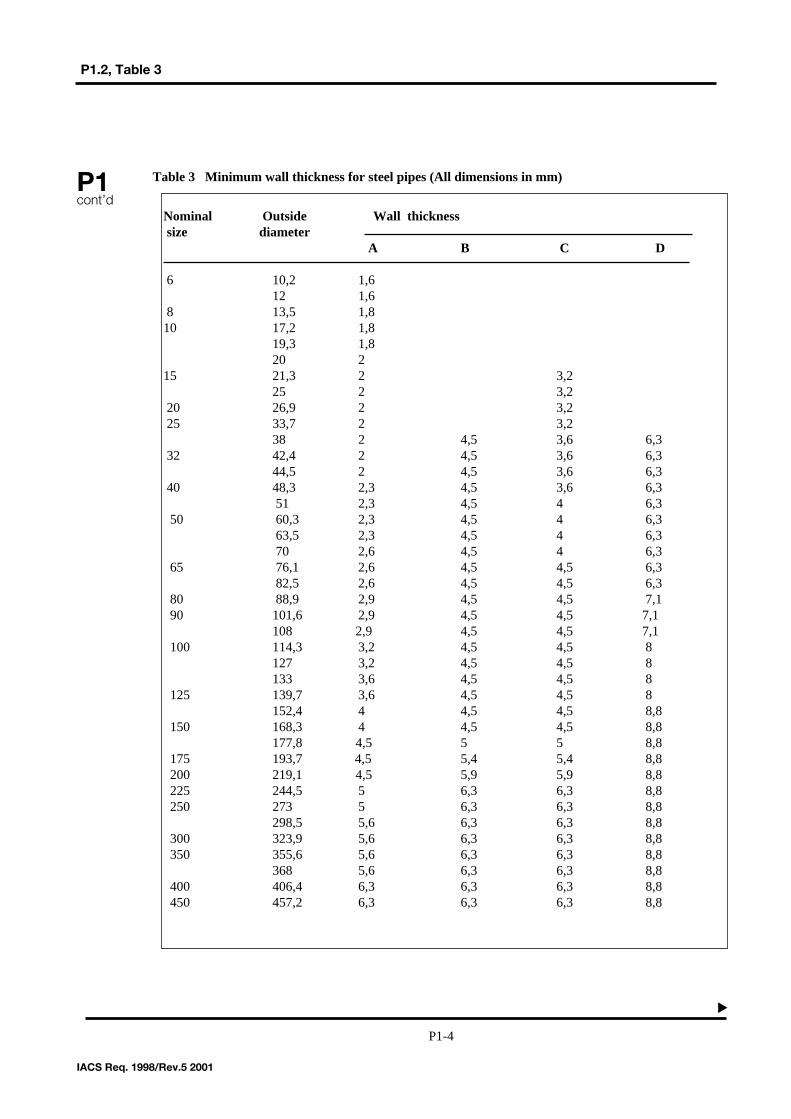
Table 3 Minimum wall thickness for steel pipes (All dimensions in mm)P1cont’d
IACS Req. 1998/Rev.5 2001
▲
Nominal Outside Wall thickness size diameter
A B C D
6 10,2 1,612 1,6
8 13,5 1,810 17,2 1,8
19,3 1,820 2
15 21,3 2 3,225 2 3,2
20 26,9 2 3,225 33,7 2 3,2
38 2 4,5 3,6 6,332 42,4 2 4,5 3,6 6,3
44,5 2 4,5 3,6 6,340 48,3 2,3 4,5 3,6 6,3
51 2,3 4,5 4 6,350 60,3 2,3 4,5 4 6,3
63,5 2,3 4,5 4 6,370 2,6 4,5 4 6,3
65 76,1 2,6 4,5 4,5 6,382,5 2,6 4,5 4,5 6,3
80 88,9 2,9 4,5 4,5 7,190 101,6 2,9 4,5 4,5 7,1
108 2,9 4,5 4,5 7,1100 114,3 3,2 4,5 4,5 8
127 3,2 4,5 4,5 8133 3,6 4,5 4,5 8
125 139,7 3,6 4,5 4,5 8152,4 4 4,5 4,5 8,8
150 168,3 4 4,5 4,5 8,8177,8 4,5 5 5 8,8
175 193,7 4,5 5,4 5,4 8,8200 219,1 4,5 5,9 5,9 8,8225 244,5 5 6,3 6,3 8,8250 273 5 6,3 6,3 8,8
298,5 5,6 6,3 6,3 8,8300 323,9 5,6 6,3 6,3 8,8350 355,6 5,6 6,3 6,3 8,8
368 5,6 6,3 6,3 8,8400 406,4 6,3 6,3 6,3 8,8450 457,2 6,3 6,3 6,3 8,8
P1-4
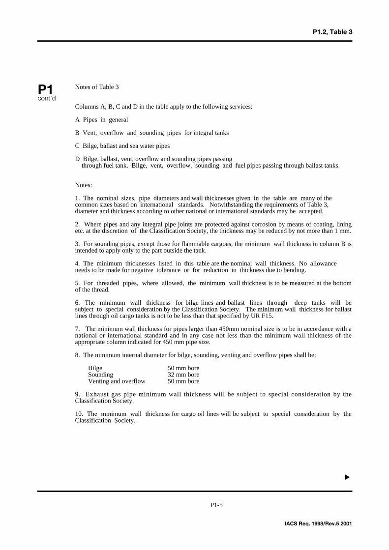
Notes of Table 3
Columns A, B, C and D in the table apply to the following services:
A Pipes in general
B Vent, overflow and sounding pipes for integral tanks
C Bilge, ballast and sea water pipes
D Bilge, ballast, vent, overflow and sounding pipes passingthrough fuel tank. Bilge, vent, overflow, sounding and fuel pipes passing through ballast tanks.
Notes:
1. The nominal sizes, pipe diameters and wall thicknesses given in the table are many of the common sizes based on international standards. Notwithstanding the requirements of Table 3,diameter and thickness according to other national or international standards may be accepted.
2. Where pipes and any integral pipe joints are protected against corrosion by means of coating, liningetc. at the discretion of the Classification Society, the thickness may be reduced by not more than 1 mm.
3. For sounding pipes, except those for flammable cargoes, the minimum wall thickness in column B isintended to apply only to the part outside the tank.
4. The minimum thicknesses listed in this table are the nominal wall thickness. No allowance needs to be made for negative tolerance or for reduction in thickness due to bending.
5. For threaded pipes, where allowed, the minimum wall thickness is to be measured at the bottomof the thread.
6. The minimum wall thickness for bilge lines and ballast lines through deep tanks will besubject to special consideration by the Classification Society. The minimum wall thickness for ballastlines through oil cargo tanks is not to be less than that specified by UR F15.
7. The minimum wall thickness for pipes larger than 450mm nominal size is to be in accordance with anational or international standard and in any case not less than the minimum wall thickness of theappropriate column indicated for 450 mm pipe size.
8. The minimum internal diameter for bilge, sounding, venting and overflow pipes shall be:
Bilge 50 mm boreSounding 32 mm boreVenting and overflow 50 mm bore
9. Exhaust gas pipe minimum wall thickness will be subject to special consideration by theClassification Society.
10. The minimum wall thickness for cargo oil lines will be subject to special consideration by theClassification Society.
P1cont’d
IACS Req. 1998/Rev.5 2001
▲
P1.2, Table 3
P1-5
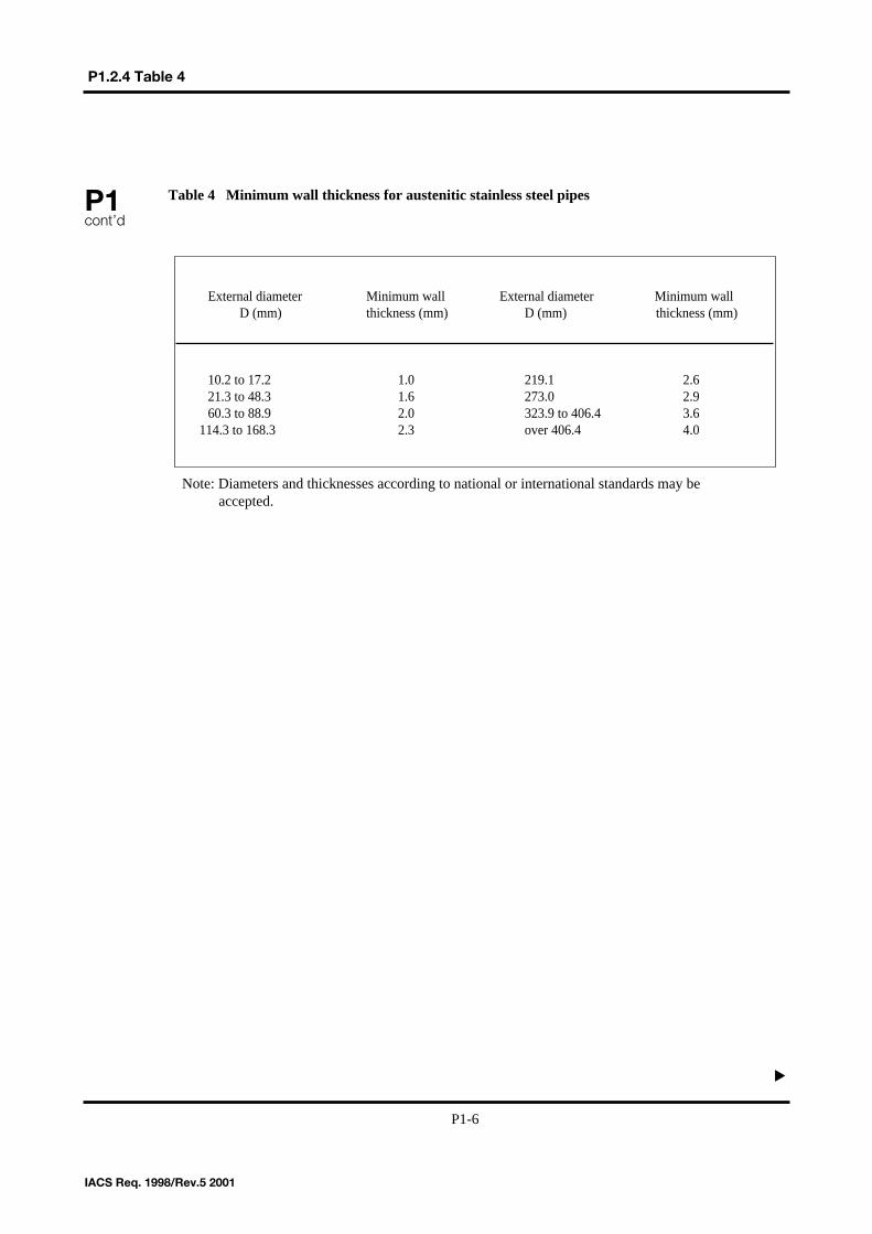
Table 4 Minimum wall thickness for austenitic stainless steel pipesP1cont’d
IACS Req. 1998/Rev.5 2001
External diameter Minimum wall External diameter Minimum wallD (mm) thickness (mm) D (mm) thickness (mm)
10.2 to 17.2 1.0 219.1 2.621.3 to 48.3 1.6 273.0 2.960.3 to 88.9 2.0 323.9 to 406.4 3.6
114.3 to 168.3 2.3 over 406.4 4.0
P1.2.4 Table 4▲
P1-6
Note: Diameters and thicknesses according to national or international standards may be accepted.
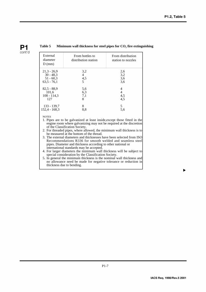
Table 5 Minimum wall thickness for steel pipes for CO2 fire extinguishing
P1.2, Table 5
P1cont’d
IACS Req. 1998/Rev.5 2001
21,3 - 26,9 3,2 2,630 - 48,3 4 3,251 - 60,3 4,5 3,6
63,5 - 76,1 5 3,6
82,5 - 88,9 5,6 4101,6 6,3 4
108 - 114,3 7,1 4,5127 8 4,5
133 - 139,7 8 5152,4 - 168,3 8,8 5,6
NOTES1. Pipes are to be galvanized at least inside,except those fitted in the
engine room where galvanizing may not be required at the discretion of the Classification Society.
2. For threaded pipes, where allowed, the minimum wall thickness is to be measured at the bottom of the thread.
3. The external diameters and thicknesses have been selected from ISO Recommendations R336 for smooth welded and seamless steel pipes. Diameter and thickness according to other national or international standards may be accepted.
4. For larger diameters the minimum wall thickness will be subject to special consideration by the Classification Society.
5. In general the minimum thickness is the nominal wall thickness and no allowance need be made for negative tolerance or reduction in thickness due to bending.
ExternaldiameterD (mm)
From bottles to distribution station
From distribution station to nozzles
▲
P1-7
P1.2.5–P1.2.6
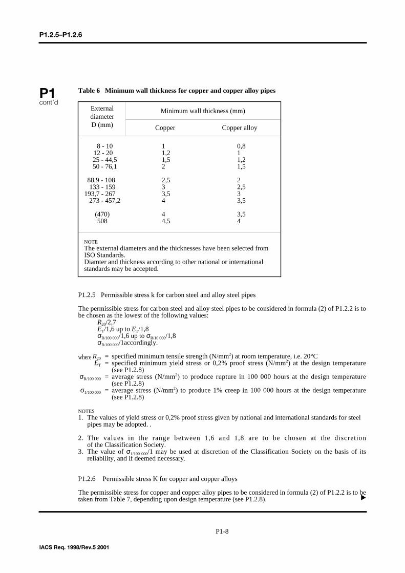
Table 6 Minimum wall thickness for copper and copper alloy pipes
P1.2.5 Permissible stress k for carbon steel and alloy steel pipes
The permissible stress for carbon steel and alloy steel pipes to be considered in formula (2) of P1.2.2 is tobe chosen as the lowest of the following values:
R20/2,7ET/1,6 up to ET/1,8σR/100 000/1,6 up to σR/10 000/1,8σR/100 000/1accordingly.
where R20 = specified minimum tensile strength (N/mm2) at room temperature, i.e. 20°CET = specified minimum yield stress or 0,2% proof stress (N/mm2) at the design temperature
(see P1.2.8)σR/100 000 = average stress (N/mm2) to produce rupture in 100 000 hours at the design temperature
(see P1.2.8)σ1/100 000 = average stress (N/mm2) to produce 1% creep in 100 000 hours at the design temperature
(see P1.2.8)
NOTES1. The values of yield stress or 0,2% proof stress given by national and international standards for steel
pipes may be adopted. .
2. The values in the range between 1,6 and 1,8 are to be chosen at the discretion of the Classification Society.
3. The value of σ1/100 000/1 may be used at discretion of the Classification Society on the basis of its reliability, and if deemed necessary.
P1.2.6 Permissible stress K for copper and copper alloys
The permissible stress for copper and copper alloy pipes to be considered in formula (2) of P1.2.2 is to betaken from Table 7, depending upon design temperature (see P1.2.8).
P1cont’d
IACS Req. 1998/Rev.5 2001
▲
8 - 10 1 0,812 - 20 1,2 125 - 44,5 1,5 1,250 - 76,1 2 1,5
88,9 - 108 2,5 2133 - 159 3 2,5
193,7 - 267 3,5 3273 - 457,2 4 3,5
(470) 4 3,5508 4,5 4
NOTEThe external diameters and the thicknesses have been selected from ISO Standards.Diamter and thickness according to other national or internationalstandards may be accepted.
ExternaldiameterD (mm)
Minimum wall thickness (mm)
Copper Copper alloy
P1-8
P1.2.6 - P1.2.7
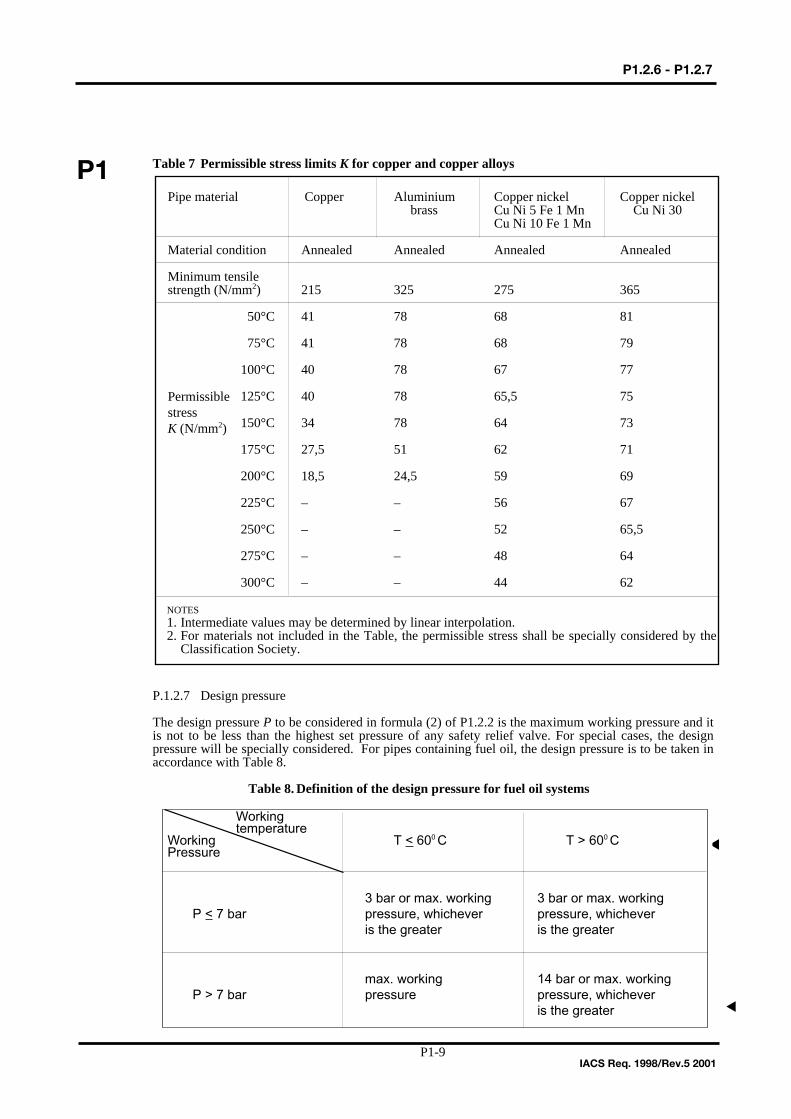
Table 7 Permissible stress limits K for copper and copper alloys
P.1.2.7 Design pressure
The design pressure P to be considered in formula (2) of P1.2.2 is the maximum working pressure and itis not to be less than the highest set pressure of any safety relief valve. For special cases, the designpressure will be specially considered. For pipes containing fuel oil, the design pressure is to be taken inaccordance with Table 8.
Table 8. Definition of the design pressure for fuel oil systems
P1
IACS Req. 1998/Rev.5 2001
Pipe material Copper Aluminium Copper nickel Copper nickelbrass Cu Ni 5 Fe 1 Mn Cu Ni 30
Cu Ni 10 Fe 1 Mn
Material condition Annealed Annealed Annealed Annealed
Minimum tensilestrength (N/mm2) 215 325 275 365
50°C 41 78 68 81
75°C 41 78 68 79
100°C 40 78 67 77
125°C 40 78 65,5 75
150°C 34 78 64 73
175°C 27,5 51 62 71
200°C 18,5 24,5 59 69
225°C – – 56 67
250°C – – 52 65,5
275°C – – 48 64
300°C – – 44 62
NOTES1. Intermediate values may be determined by linear interpolation.2. For materials not included in the Table, the permissible stress shall be specially considered by the
Classification Society.
PermissiblestressK (N/mm2)
▲
P1-9
▲
Working temperature
Working T < 600 C T > 600 CPressure
3 bar or max. working 3 bar or max. workingP < 7 bar pressure, whichever pressure, whichever
is the greater is the greater
max. working 14 bar or max. workingP > 7 bar pressure pressure, whichever
is the greater
P1.2.8- 1.4
P1cont’d
IACS Req. 2001
P1.2.8 Design temperature
The design temperature to be considered for determining the permissible stress in P1.2.5 and P1.2.6 is ingeneral the maximum temperature of the medium inside the pipes. For special cases, the designtemperature will be specially considered.
P1.3 Flanges
The dimensions of flanges and relative bolts are to be chosen in accordance with the national standards.For special application the dimensions of flanges and relative bolts will be subject to specialconsideration*.
*For special applications, when the temperature, the pressure and the size of the flange have valuesabove certain limits, to be fixed, the complete calculation of bolts and flanges is to be carried out.
P1.4 Valves and Fittings
Valves and fittings in piping systems are to be compatible with the pipes to which they are attached inrespect of their strength (see P1.2.7 for design pressure) and are to be suitable for effective operation atthe maximum working pressure they will experience in service.
P1.3(1972(Rev. 11987)
P1.4(Nov.2001)
▲▲
▲ ▲
P1-10
P2.1
Page 1 of 38 IACS Req. 1981/Rev.2 2001
P2 (cont)
Rules for piping design, construction and testing P2.1 Foreword (1981) (Rev.1 1987) (Rev.2 Nov 2001) The present requirements are related to piping-systems made of carbon, carbon-manganese, alloy steels or non-ferrous material normally installed on board ships for services considered in Table 1. These requirements cover the following services: Air, vapour, gas (excluding liquefied gas cargo and process piping), water, lubricating oil, fuel oil, hydraulic fluid systems for steering gear, toxic gas and liquids, cargo oil and tank cleaning piping and open ended lines such as drains, overflows, vents and boiler escape pipes. They do not include pipes forming integral part of a boiler. Hydraulic fluid systems other than those for steering gear shall be specially considered by each individual Classification Society. Piping systems intended for liquefied gases (cargo and process) are dealt with in UR G3 and W1. These requirements do not apply to cargo piping systems of ships carrying chemicals in bulk.
P2
End of Section
P2.2
Page 2 of 38 IACS Req. 1974/Rev.4 2001
P2 (cont)
P2.2 Classes of pipes (1974) (Rev.1 1975) (Rev.2 1987) (Rev.3 May 2000) (Rev.4 Nov. 2001) For the purpose of testing, the type of joint to be adopted, heat treatment and welding procedure, pipes are subdivided into three classes as indicated in Figure 1 and Table 1.
End of Section
P2.3
Page 3 of 38 IACS Req. 1974/Rev.2 2001
P2 (cont)
P2.3 Materials (1974) (Rev.1 1987) (Rev.2 Nov 2001) The materials to be used for the various pipes, valves and fittings are to be suitable for the medium and service for which the piping is intended (see P2.3.1 to P2.3.4). In the case of especially corrosive media, the materials for the piping system will be considered by the Classification Society in each particular case. P2.3.1 Steel pipes, valves and other fittings Pipes belonging to Classes I and II are to be seamless drawn steel pipes or pipes fabricated with a welding procedure, considered by the Society to be equivalent to seamless pipes. In general, carbon and carbon-manganese steel pipes, valves and other fittings are not to be employed for temperatures above 400°C. Nevertheless, they may be used for higher temperatures if their metallurgical behaviour and time dependent strength (UTS after 100 000 hours) are in accordance with national or international codes or standards and if such valves are guaranteed by the steel manufacturer. Otherwise, special alloy steel pipes, valve and fittings should be employed according to Rules on materials of the Classification Society. P2.3.2 Copper and copper alloy pipes, valves and fittings Copper and copper alloy piping shall be of seamless drawn material or other type approved by the Classification Society. Copper pipes for Classes I and II are to be seamless. In general, copper and copper alloy piping, valves and fittings shall not be used for media having temperature above the following limits: .1 Copper and aluminium brass 200°C .2 Copper nickel 300°C (see Table 6 of P1). Special bronze suitable for high temperature services may be accepted in general up to 260°C. P2.3.3 Nodular cast iron pipes, valves and other fittings Nodular cast iron of the ferritic type according to the material rules of the Classification Society may be accepted for bilge, ballast and cargo oil piping. Ferritic nodular cast iron valves and other fittings may be accepted for media having temperatures not exceeding 350°C. The use of this material for pipes, valves and fittings for other services, in principle Classes II and III, will be subject to special consideration.
P2.3
Page 4 of 38 IACS Req. 1974/Rev.2 2001
P2 (cont)
Nodular cast iron pipes and valves fitted on the ship's side should have specified properties to the Classification Society's satisfaction, according to the intention of Regulation 22 of the 1966 Convention on Load Lines. P2.3.4 Ordinary cast iron pipes, valves and fittings Ordinary cast iron pipes, valves and fittings may be accepted in principle for Class III at the Classification Society's judgement. Ordinary cast iron piping may be accepted for cargo oil lines within cargo tanks of tankers. Ordinary cast iron is not to be used for pipes, valves and other fittings handling media having temperature above 220°C and for piping subject to pressure shock, excessive strains and vibrations. Ordinary cast iron may be accepted for pressures up to 16 bar for cargo oil pipelines on weather decks of oil tankers except for manifolds and their valves and fittings connected to cargo handling hoses. Ordinary cast iron shall not be used for sea valves and pipes fitted on the ship sides, and for valves fitted on the collision bulkhead. The use of cast iron for other services will be subject to special consideration in each case.
End of Section
P2.4
Page 5 of 38 IACS Req. 1974
P2 (cont)
P2.4 Testing of Materials (1974) Material for pipes, valves and relative fittings belonging to Classes I and II and for valves and pipes fitted on the ship's side and for valves fitted on the collision bulkhead are to be tested in accordance with applicable Rules of the individual Classification Society. The individual Classification Society may require internal workshop certificates for pipes, valves and fittings belonging to Class III.
End of Section
P2.5
Page 6 of 38 IACS Req. 1974/Corr. 2001
P2 (cont)
P2.5 Welding (1974) (Rev. 1 1987) (Corr. Nov 2001) P2.5.1 General The welding joints belonging to Class I or II piping systems shall be effected by approved procedures. Consumables and welders shall meet the requirements of the Classification Society's Rules. Joint preparations and tolerance shall be appropriate to the welding process, in accordance with the Classification Society's Rules or recognized standards. Welding shall be done according to applicable requirements and good practice; the weld preparations and the welded joint shall be inspected as may be necessary in the course of fabrication and after completion of the welding heat treatment. For non-destructive tests, see P2.6. The following requirements apply to the fabrication of Classes I and II piping systems operating at ambient or high temperature and made of steel of the types given hereunder: .1 carbon and carbon-manganese steels having minimum tensile strength (Rm) 320,
360, 410, 460 and 490 N/mm2. .2 low alloy carbon-molybdenum, chromium-molybdenum, chromium-molybdenum-
vanadium steels having chemical composition 0,3 Mo; 1 Cr - 0,5 Mo; 2,25 Cr - 1 Mo; 0,5 Cr - 0,5 Mo - 0,25 V.
At the discretion of the Society, these requirements may be applied also to the Class III piping systems and to repair welding of pipelines. Refrigerated cargo installations piping systems operating at temperatures lower than -40°C will be given special consideration by each Society. P2.5.2 Edge preparation for welded joints Edge preparation is to be in accordance with recognized standards and/or approved drawings. The preparation of the edges shall be preferably carried out by mechanical means. When flame cutting is used, care should be taken to remove the oxide scales and any notch due to irregular cutting by matching grinding or chipping back to sound metal. P2.5.3 Alignment and assembling P2.5.3.1 Unless otherwise agreed by the Society, the tolerances on the alignment of the pipes to be welded are to be as follows:
.1 Pipes of all diameters and thicknesses welded with permanently fitted backing ring: 0,5 mm.
.2 Pipes welded without fitted backing ring:
P2.5
Page 7 of 38 IACS Req. 1974/Corr. 2001
P2 (cont)
.2.1 inside diameter less than 150 mm, thickness up to 6 mm included -
1 mm or 4t whichever is less;
.2.2 inside diameter less than 300 mm, thickness up to 9,5 mm included -
1,5 mm or 4t whichever is less;
.2.3 inside diameter 300 mm and over, or over thickness 9,5 mm included -
2,0 mm or 4t whichever is less.
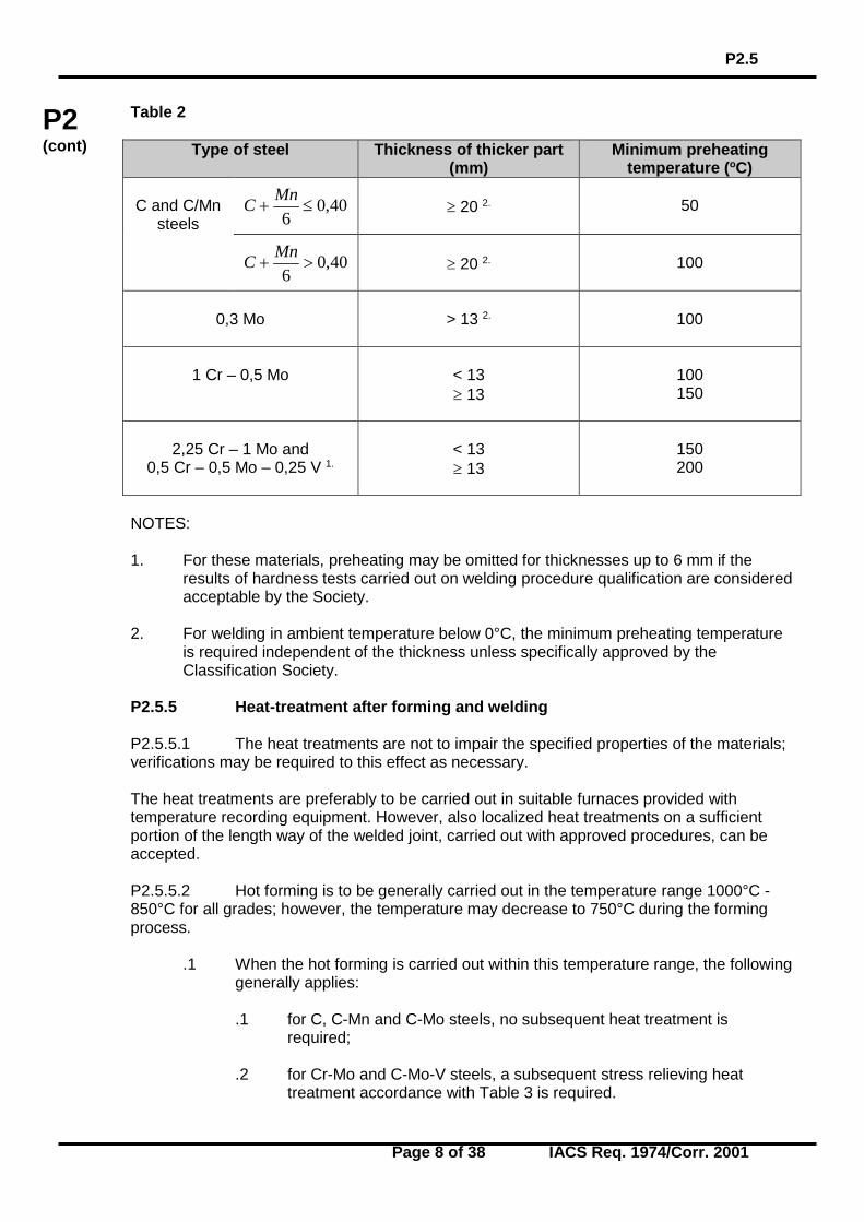
NOTE: For Class III piping systems, the requirements for alignment tolerances may be waived at the discretion of the Society. P2.5.3.2 Assembling for welding is to be appropriate and within the prescribed tolerances. Tack welds should be made with an electrode suitable for the base metal; tack welds which form part of the finished weld should be made using approved procedures. When welding materials require preheating, the same preheating should be applied during tack welding. P2.5.4 Preheating Preheating of the different types of steels will be dependent upon their thickness and chemical composition as indicated in Table 2. In any case, dryness is to be ensured using, if necessary, suitable preheating. Table 2 values are based on use of low hydrogen processes; consideration should be given to using higher preheating temperatures when low hydrogen processes are not used.
P2.5
Page 8 of 38 IACS Req. 1974/Corr. 2001
P2 (cont)
Table 2
Type of steel
Thickness of thicker part (mm)
Minimum preheating temperature (oC)
C and C/Mn
steels 40,0
6≤+
MnC
≥ 20 2.
50
40,06
>+MnC
≥ 20 2.
100
0,3 Mo
> 13 2.
100
1 Cr – 0,5 Mo
< 13 ≥ 13
100 150
2,25 Cr – 1 Mo and 0,5 Cr – 0,5 Mo – 0,25 V 1.
< 13 ≥ 13
150 200
NOTES: 1. For these materials, preheating may be omitted for thicknesses up to 6 mm if the
results of hardness tests carried out on welding procedure qualification are considered acceptable by the Society.
2. For welding in ambient temperature below 0°C, the minimum preheating temperature
is required independent of the thickness unless specifically approved by the Classification Society.
P2.5.5 Heat-treatment after forming and welding P2.5.5.1 The heat treatments are not to impair the specified properties of the materials; verifications may be required to this effect as necessary. The heat treatments are preferably to be carried out in suitable furnaces provided with temperature recording equipment. However, also localized heat treatments on a sufficient portion of the length way of the welded joint, carried out with approved procedures, can be accepted. P2.5.5.2 Hot forming is to be generally carried out in the temperature range 1000°C - 850°C for all grades; however, the temperature may decrease to 750°C during the forming process.
.1 When the hot forming is carried out within this temperature range, the following generally applies:
.1 for C, C-Mn and C-Mo steels, no subsequent heat treatment is
required;
.2 for Cr-Mo and C-Mo-V steels, a subsequent stress relieving heat treatment accordance with Table 3 is required.
P2.5
Page 9 of 38 IACS Req. 1974/Corr. 2001
P2 (cont)
.2 When the hot forming is carried outside the above temperature range, a subsequent new heat treatment in accordance with Table 4 is generally required for all grades.
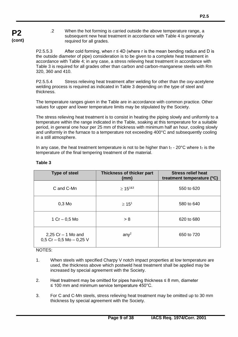
P2.5.5.3 After cold forming, when r ≤ 4D (where r is the mean bending radius and D is the outside diameter of pipe) consideration is to be given to a complete heat treatment in accordance with Table 4; in any case, a stress relieving heat treatment in accordance with Table 3 is required for all grades other than carbon and carbon-manganese steels with Rm 320, 360 and 410. P2.5.5.4 Stress relieving heat treatment after welding for other than the oxy-acetylene welding process is required as indicated in Table 3 depending on the type of steel and thickness. The temperature ranges given in the Table are in accordance with common practice. Other values for upper and lower temperature limits may be stipulated by the Society. The stress relieving heat treatment is to consist in heating the piping slowly and uniformly to a temperature within the range indicated in the Table, soaking at this temperature for a suitable period, in general one hour per 25 mm of thickness with minimum half an hour, cooling slowly and uniformly in the furnace to a temperature not exceeding 400°C and subsequently cooling in a still atmosphere. In any case, the heat treatment temperature is not to be higher than tT - 20°C where tT is the temperature of the final tempering treatment of the material. Table 3
Type of steel
Thickness of thicker part (mm)
Stress relief heat treatment temperature (oC)
C and C-Mn
≥ 151&3
550 to 620
0,3 Mo
≥ 151
580 to 640
1 Cr – 0,5 Mo
> 8
620 to 680
2,25 Cr – 1 Mo and 0,5 Cr – 0,5 Mo – 0,25 V
any2
650 to 720
NOTES: 1. When steels with specified Charpy V notch impact properties at low temperature are
used, the thickness above which postweld heat treatment shall be applied may be increased by special agreement with the Society.
2. Heat treatment may be omitted for pipes having thickness ≤ 8 mm, diameter
≤ 100 mm and minimum service temperature 450°C. 3. For C and C-Mn steels, stress relieving heat treatment may be omitted up to 30 mm
thickness by special agreement with the Society.
P2.5
Page 10 of 38 IACS Req. 1974/Corr. 2001
P2 (cont)
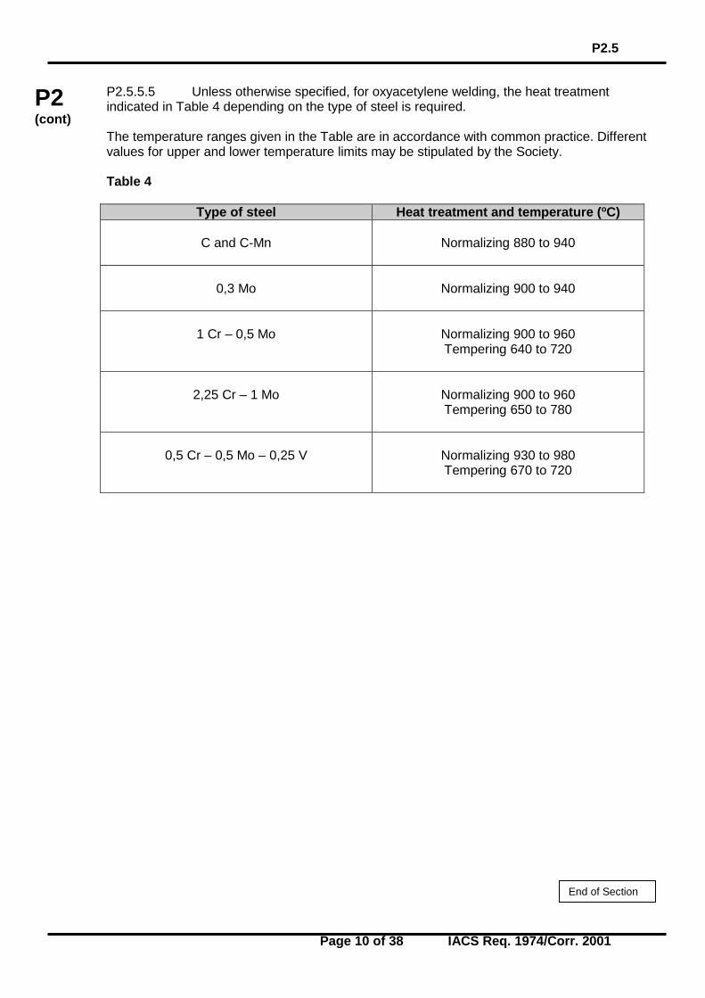
P2.5.5.5 Unless otherwise specified, for oxyacetylene welding, the heat treatment indicated in Table 4 depending on the type of steel is required. The temperature ranges given in the Table are in accordance with common practice. Different values for upper and lower temperature limits may be stipulated by the Society. Table 4
Type of steel Heat treatment and temperature (oC)
C and C-Mn
Normalizing 880 to 940
0,3 Mo
Normalizing 900 to 940
1 Cr – 0,5 Mo
Normalizing 900 to 960 Tempering 640 to 720
2,25 Cr – 1 Mo
Normalizing 900 to 960 Tempering 650 to 780
0,5 Cr – 0,5 Mo – 0,25 V
Normalizing 930 to 980 Tempering 670 to 720
End of Section
P2.6
Page 11 of 38 IACS Req. 1987
P2 (cont)
P2.6 Non destructive testing of welds and acceptance criteria (1987) P2.6.1 In general, the welded joints including the inside wherever possible shall be visually examined and non destructive tests will be required depending on the class of pipes and type of joint as hereunder indicated. .1 Butt-welded joints - Radiographic examination is to be required as follows:
.1.1 pipes of Class I: full radiographic examination when the outside diameter is greater than 75 mm;
.1.2 pipes of Class II: at least 10% random radiography when the outside diameter
is greater than 100 mm.
More stringent requirements may be applied at the Society's discretion depending on the kind of materials, welding procedure and controls during the fabrication. An approved ultrasonic testing procedure may be accepted, at the Society's discretion, in lieu of radiographic testing when the conditions are such that a comparable level of weld quality is assured.
.2 Fillet welds of flange pipe connections are to be examined by the magnetic particle method or by other appropriate non-destructive methods, in case of Class I pipes.
In other cases, magnetic particle examination or equivalent non-destructive testing may be required at the discretion of the Surveyor. .3 Ultrasonic examination in addition to the above non-destructive testing may be
required in special cases at the Society's discretion. P2.6.2 Radiographic and ultrasonic examination is to be performed with an appropriate technique by trained operators. At the request of the Society, complete details of the radiographic or ultrasonic technique is to be submitted for approval. P2.6.3 Magnetic particle examination is to be performed with suitable equipment and procedures, and with a magnetic flux output sufficient for defect detection. The equipment may be required to be checked against standard samples. P2.6.4 The welds are to meet the acceptable standard level as required by the individual Society. Unacceptable defects are to be removed and repaired according to the satisfaction of the Society.
End of Section
P2.7-2.7.3
Page 12 of 38 IACS Req. 1974/Rev.2 2001
P2 (cont)
P2.7 Types of connections (1974) (Rev.1 1987) (Rev.2 Nov 2001) Direct connections of pipe lengths may be made by direct welding, flanges, threaded joints or mechanical joints, and should be to a recognised standard or of a design proven to be suitable for the intended purpose and acceptable to the Classification Society. The expression "mechanical joints" means devices intended for direct connection of pipe lengths other than by welding, flanges or threaded joints described in 2.7.1, 2.7.2 and 2.7.3 below. P2.7.1 Welded connections Welding and non destructive testing of welds are to be carried out in accordance with P2.5 and P2.6 and requirements of Classification Society. P2.7.1.1 Butt welded joints Butt welded joints shall be of full penetration type generally with or without special provision for a high quality of root side.* Butt welded joints with special provision for a high quality of root side may be used for piping of any Class, any outside diameter. Butt welded joints without special provision for a high quality of root side may be used for piping systems of Class II and III irrespective of outside diameter. P2.7.1.2 Slip-on sleeve and socket welded joints Slip-on sleeve and socket welded joints are to have sleeves, sockets and weldments of adequate dimensions conforming to Classification Society Rules or recognized Standard. Slip-on sleeve and socket welded joints may be used in Class III systems, any outside diameter. In particular cases, slip-on sleeve and socket welded joints may be allowed by the Classification Society for piping systems of Class I and II having outside diameter ≤ 88.9 mm except for piping systems conveying toxic media or services where fatigue, severe erosion or crevice corrosion is expected to occur. P2.7.2 Flange connections P2.7.2.1 The dimensions and configuration of flanges and bolts are to be chosen in accordance with recognized standards. * The expression “special provision for a high quality of root side” means that butt welds
were accomplished as double welded or by use of a backing ring or inert gas back-up on first pass, or other similar methods accepted by the Classification Society.
P2.7-2.7.3
Page 13 of 38 IACS Req. 1974/Rev.2 2001
P2 (cont)
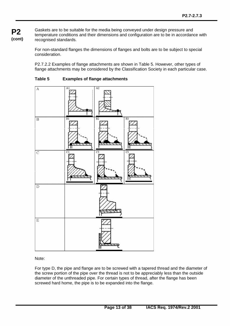
Gaskets are to be suitable for the media being conveyed under design pressure and temperature conditions and their dimensions and configuration are to be in accordance with recognised standards. For non-standard flanges the dimensions of flanges and bolts are to be subject to special consideration. P2.7.2.2 Examples of flange attachments are shown in Table 5. However, other types of flange attachments may be considered by the Classification Society in each particular case. Table 5 Examples of flange attachments
Note: For type D, the pipe and flange are to be screwed with a tapered thread and the diameter of the screw portion of the pipe over the thread is not to be appreciably less than the outside diameter of the unthreaded pipe. For certain types of thread, after the flange has been screwed hard home, the pipe is to be expanded into the flange.
P2.7-2.7.3
Page 14 of 38 IACS Req. 1974/Rev.2 2001
P2 (cont)
P2.7.2.3 Flange attachments are to be in accordance with national or international standards that are applicable to the piping system and are to recognize the boundary fluids, design pressure and temperature conditions, external or cyclic loading and location. P2.7.3 Slip-on threaded joints Slip-on threaded joints having pipe threads where pressure-tight joints are made on the threads with parallel or tapered threads, shall comply with requirements of a recognized national or international standard. Slip-on threaded joints may be used for outside diameters as stated below except for piping systems conveying toxic or flammable media or services where fatigue, severe erosion or crevice corrosion is expected to occur. Threaded joints in CO2 systems shall be allowed only inside protected spaces and in CO2 cylinder rooms. Threaded joints for direct connectors of pipe lengths with tapered thread are to be allowed for: a) Class I, outside diameter not more than 33.7 mm, b) Class II and Class III, outside diameter not more than 60.3 mm. Threaded joints with parallel thread are to be allowed for Class III, outside diameter not more than 60.3 mm. In particular cases, sizes in excess of those mentioned above may be accepted by the Classification Society if in compliance with a recognized national and/or international standard.
End of Section
P2.7.4
Page 15 of 38 IACS Req. 2001/Rev.8 2016
P2 (cont)
P2.7.4 Mechanical joints (Rev.5 Nov 2003) (Rev.6 May 2006) (Rev.7 Sept 2007) (Rev.8 Mar 2016) Due to the great variations in design and configuration of mechanical joints, no specific recommendation regarding calculation method for theoretical strength calculations is given in these requirements. The Type Approval is to be based on the results of testing of the actual joints. These requirements are applicable to pipe unions, compression couplings, slip-on joints as shown in Table 6. Similar joints complying with these requirements may be acceptable. P2.7.4.1 The application and pressure ratings of different mechanical joints are to be approved by the Classification Society. The approval is to be based on the Type Approval procedure in P.2.11. Mechanical joints including pipe unions, compression couplings, slip-on joints and similar joints are to be of approved type for the service conditions and the intended application. P2.7.4.2 Where the application of mechanical joints results in reduction in pipe wall thickness due to the use of bite type rings or other structural elements, this is to be taken into account in determining the minimum wall thickness of the pipe to withstand the design pressure. P2.7.4.3 Material of mechanical joints is to be compatible with the piping material and internal and external media. P2.7.4.4 Mechanical joints are to be tested where applicable, to a burst pressure of 4 times the design pressure. For design pressures above 200 bar the required burst pressure will be specially considered by the Classification Society. P2.7.4.5 Where appropriate, mechanical joints are to be of fire resistant type as required by Table 7. Note: 1. The requirements introduced in Revision 5 of UR P2.7.4 (Nov 2003), are to be
uniformly implemented by all IACS Societies, in conjunction with UR P2.11 (Nov. 2001), for application to any mechanical pipe joints submitted for approval from 1 January 2007 and to any renewal of type approval of existing design of mechanical pipe joint after 1 January 2007.
2. The requirements of UR P2.7.4 (Rev.8 Mar 2016), are to be uniformly implemented by
all IACS Societies, in conjunction with UR P2.11, for application to any mechanical pipe joints submitted for approval from 1 January 2017 and to any renewal of type approval of existing design of mechanical pipe joint after 1 January 2017.
P2.7.4
Page 16 of 38 IACS Req. 2001/Rev.8 2016
P2 (cont)
P2.7.4.6 Mechanical joints, which in the event of damage could cause fire or flooding, are not to be used in piping sections directly connected to the ship’s side below the bulkhead deck of passenger ships and freeboard deck of cargo ships or tanks containing flammable fluids. P2.7.4.7 The number of mechanical joints in flammable fluid systems is to be kept to a minimum. In general, flanged joints conforming to recognised standards are to be used. P2.7.4.8 Piping in which a mechanical joint is fitted is to be adequately adjusted, aligned and supported. Supports or hangers are not to be used to force alignment of piping at the point of connection. P2.7.4.9 Slip-on joints are not to be used in pipelines in cargo holds, tanks, and other spaces which are not easily accessible, unless approved by the Classification Society. Application of these joints inside tanks may be permitted only for the same media that is in the tanks. Usage of slip type slip-on joints as the main means of pipe connection is not permitted except for cases where compensation of axial pipe deformation is necessary. P2.7.4.10 Application of mechanical joints and their acceptable use for each service is indicated in Table 7; dependence upon the Class of piping and pipe dimensions is indicated in Table 8. In particular cases, sizes in excess of those mentioned above may be accepted by the Classification Society if in compliance with a recognized national and/or international standard. P2.7.4.11 Mechanical joints are to be tested in accordance with a program approved by the Classification Society, which is to include at least the following: .1 leakage test .2 vacuum test (where necessary) .3 vibration (fatigue) test .4 fire endurance test (where necessary) .5 burst pressure test .6 pressure pulsation test (where necessary) .7 assembly test (where necessary) .8 pull out test (where necessary) P2.7.4.12 The installation of mechanical joints is to be in accordance with the manufacturer’s assembly instructions. Where special tools and gauges are required for installation of the joints, these are to be supplied by the manufacturer.
P2.7.4
Page 17 of 38 IACS Req. 2001/Rev.8 2016
P2 (cont)
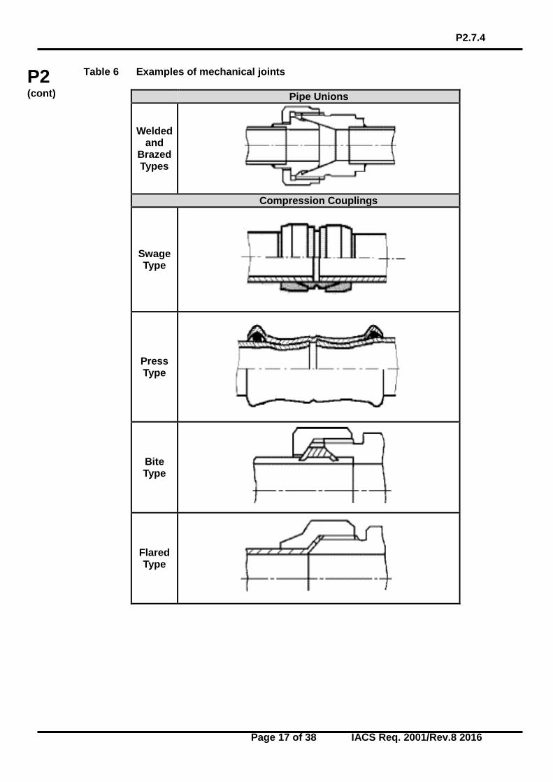
Table 6 Examples of mechanical joints
Pipe Unions
Welded and
Brazed Types
Compression Couplings
Swage Type
Press Type
Bite Type
Flared Type
P2.7.4
Page 18 of 38 IACS Req. 2001/Rev.8 2016
P2 (cont)
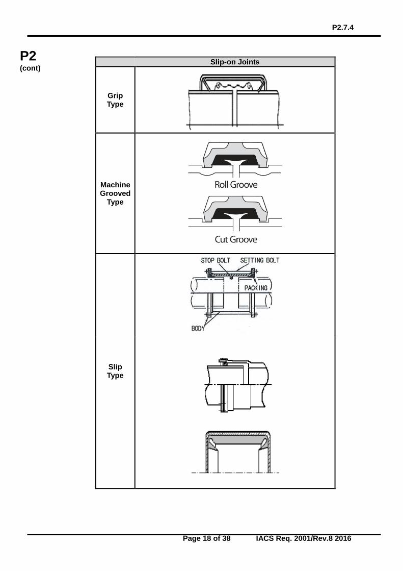
Slip-on Joints
Grip Type
Machine Grooved
Type
Slip Type
P2.7.4
Page 19 of 38 IACS Req. 2001/Rev.8 2016
P2 (cont)
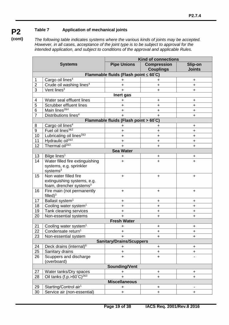
Table 7 Application of mechanical joints The following table indicates systems where the various kinds of joints may be accepted. However, in all cases, acceptance of the joint type is to be subject to approval for the intended application, and subject to conditions of the approval and applicable Rules.
Systems
Kind of connections Pipe Unions Compression
Couplings Slip-on Joints
Flammable fluids (Flash point ≤ 60°C) 1 Cargo oil lines4 + + + 2 Crude oil washing lines4 + + + 3 Vent lines3 + + +
Inert gas 4 Water seal effluent lines + + + 5 Scrubber effluent lines + + + 6 Main lines2&4 + + + 7 Distributions lines4 + + +
Flammable fluids (Flash point > 60°C) 8 Cargo oil lines4 + + + 9 Fuel oil lines3&2 + + + 10 Lubricating oil lines2&3 + + + 11 Hydraulic oil2&3 + + + 12 Thermal oil2&3 + + +
Sea Water 13 Bilge lines1 + + + 14 Water filled fire extinguishing
systems, e.g. sprinkler systems3
+ + +
15 Non water filled fire extinguishing systems, e.g. foam, drencher systems3
+ + +
16 Fire main (not permanently filled)3
+ + +
17 Ballast system1 + + + 18 Cooling water system1 + + + 19 Tank cleaning services + + + 20 Non-essential systems + + +
Fresh Water 21 Cooling water system1 + + + 22 Condensate return1 + + + 23 Non-essential system + + +
Sanitary/Drains/Scuppers 24 Deck drains (internal)6 + + + 25 Sanitary drains + + + 26 Scuppers and discharge
(overboard) + + -
Sounding/Vent 27 Water tanks/Dry spaces + + + 28 Oil tanks (f.p.>60°C)2&3 + + +
Miscellaneous 29 Starting/Control air1 + + - 30 Service air (non-essential) + + +
P2.7.4
Page 20 of 38 IACS Req. 2001/Rev.8 2016
P2 (cont)
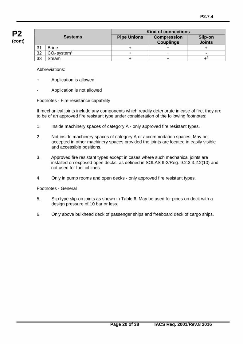
Systems
Kind of connections Pipe Unions Compression
Couplings Slip-on Joints
31 Brine + + + 32 CO2 system1 + + - 33 Steam + + +5 Abbreviations: + Application is allowed - Application is not allowed Footnotes - Fire resistance capability If mechanical joints include any components which readily deteriorate in case of fire, they are to be of an approved fire resistant type under consideration of the following footnotes: 1. Inside machinery spaces of category A - only approved fire resistant types. 2. Not inside machinery spaces of category A or accommodation spaces. May be
accepted in other machinery spaces provided the joints are located in easily visible and accessible positions.
3. Approved fire resistant types except in cases where such mechanical joints are
installed on exposed open decks, as defined in SOLAS II-2/Reg. 9.2.3.3.2.2(10) and not used for fuel oil lines.
4. Only in pump rooms and open decks - only approved fire resistant types. Footnotes - General 5. Slip type slip-on joints as shown in Table 6. May be used for pipes on deck with a
design pressure of 10 bar or less. 6. Only above bulkhead deck of passenger ships and freeboard deck of cargo ships.
P2.7.4
Page 21 of 38 IACS Req. 2001/Rev.8 2016
P2 (cont)
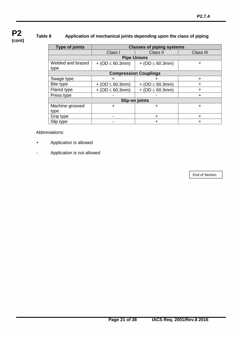
Table 8 Application of mechanical joints depending upon the class of piping
Type of joints Classes of piping systems Class I Class II Class III
Pipe Unions Welded and brazed type
+ (OD ≤ 60.3mm) + (OD ≤ 60.3mm) +
Compression Couplings Swage type + + + Bite type + (OD ≤ 60.3mm) + (OD ≤ 60.3mm) + Flared type + (OD ≤ 60.3mm) + (OD ≤ 60.3mm) + Press type - - +
Slip-on joints Machine grooved type
+ + +
Grip type - + + Slip type - + +
Abbreviations: + Application is allowed - Application is not allowed
End of Section
P2.8
Page 22 of 38 IACS Req. 1974/Corr. 2001
P2 (cont)
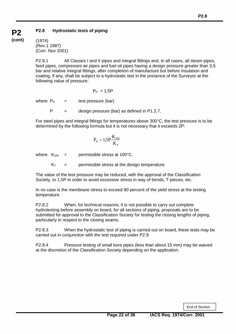
P2.8 Hydrostatic tests of piping (1974) (Rev.1 1987) (Corr. Nov 2001) P2.8.1 All Classes I and II pipes and integral fittings and, in all cases, all steam pipes, feed pipes, compresses air pipes and fuel oil pipes having a design pressure greater than 3,5 bar and relative integral fittings, after completion of manufacture but before insulation and coating, if any, shall be subject to a hydrostatic test in the presence of the Surveyor at the following value of pressure: PH = 1,5P where PH = test pressure (bar)
P = design pressure (bar) as defined in P1.2.7. For steel pipes and integral fittings for temperatures above 300°C, the test pressure is to be determined by the following formula but it is not necessary that it exceeds 2P:
T
100H K
KP5,1P =
where K100 = permissible stress at 100°C. KT = permissible stress at the design temperature. The value of the test pressure may be reduced, with the approval of the Classification Society, to 1,5P in order to avoid excessive stress in way of bends, T-pieces, etc. In no case is the membrane stress to exceed 90 percent of the yield stress at the testing temperature. P2.8.2 When, for technical reasons, it is not possible to carry out complete hydrotesting before assembly on board, for all sections of piping, proposals are to be submitted for approval to the Classification Society for testing the closing lengths of piping, particularly in respect to the closing seams. P2.8.3 When the hydrostatic test of piping is carried out on board, these tests may be carried out in conjunction with the test required under P2.9. P2.8.4 Pressure testing of small bore pipes (less than about 15 mm) may be waived at the discretion of the Classification Society depending on the application.
End of Section
P2.9
Page 23 of 38 IACS Req. 1974/Rev.2 1987
P2 (cont)
P2.9 Pressure tests of piping after assembly on board (1974) (Rev.1 1975) (Rev.2 1987) After assembly on board, the following tightness tests are to be carried out in the presence of the Surveyor. In general, all the piping systems covered by these requirements are to be checked for leakage under operational conditions and, if necessary, using special techniques other than hydrostatic testing. In particular, heating coils in tanks and liquid or gas fuel lines are to be tested to not less than 1,5P but in no case less than 4 bar.
End of Section
P2.10
Page 24 of 38 IACS Req. 1975/Rev.2 2001
P2 (cont)
P2.10 Hydrostatic tests of valves and fittings (1975) (Rev.1 1987) (Rev.2 Nov 2001) Valves and fittings non-integral with the piping system, intended for Classes I and II, are to be tested in accordance with recognized standards, but to not less than 1,5 times the design pressure. Valves and cocks intended to be fitted on the ship side below the load waterline are to be tested by hydraulic pressure not less than 5 bar.
End of Section
P2.11
Page 25 of 38 IACS Req. 2001/Rev.4 2016
P2 (cont)
P2.11 Type Approval of Mechanical Joints (Nov. 2001) (Rev.1 May 2006) (Rev.2 Nov 2006) (Corr.1 Apr 2007) (Rev.3 Aug 2012) (Rev.4 Mar 2016) P2.11.1 General This specification describes the type testing condition for type approval of mechanical joints intended for use in marine piping systems. Conditions outlined in these requirements are to be fulfilled before Type Approval Certificates are issued. Individual Societies may specify more severe testing conditions and additional tests if considered necessary to ensure the intended reliability and also accept alternative testing in accordance with national or international standards where applicable to the intended use and application. P2.11.2 Scope This specification is applicable to mechanical joints defined in UR P2.7.4 including compression couplings and slip-on joints of different types for marine use. P2.11.3 Documentation Following documents and information are to be submitted by Manufacturer for assessment and/or approval: .1 product quality assurance system implemented; .2 complete description of the product; Notes: 1. The requirements of UR P2.11 (Nov 2001) are to be uniformly implemented by all IACS Societies for application to any mechanical pipe joints submitted for approval from 1 January 2007 and to any renewal of type approval of existing design of mechanical pipe joint after 1 January 2007. 2. The requirements of UR P2.11 Rev.3 (Aug 2012) are to be uniformly implemented by all IACS Societies for application to any mechanical pipe joints submitted for approval from 1 January 2014 and to any renewal of type approval of existing design of mechanical pipe joint after 1 January 2014. 3. The requirements of UR P2.11 Rev.4 (Mar 2016) are to be uniformly implemented by all IACS Societies for application to any mechanical pipe joints submitted for approval from 1 January 2017 and to any renewal of type approval of existing design of mechanical pipe joint after 1 January 2017.
P2.11
Page 26 of 38 IACS Req. 2001/Rev.4 2016
P2 (cont)
.3 typical sectional drawings with all dimensions necessary for evaluation of joint design; .4 complete specification of materials used for all components of the assembly; .5 proposed test procedure as required in P2.11.5 and corresponding test reports or other previous relevant tests; .6 initial information:
- maximum design pressures (pressure and vacuum); - maximum and minimum design temperatures;
- conveyed media; - intended services;
- maximum axial, lateral and angular deviation, allowed by manufacturer;
- installation details.
P2.11.4 Materials The materials used for mechanical joints are to comply with the requirements of P2.7.4.3. The manufacturer has to submit evidence to substantiate that all components are adequately resistant to working the media at design pressure and temperature specified. P2.11.5 Testing, procedures and requirements The aim of tests is to demonstrate ability of the pipe joints to operate satisfactory under intended service conditions. The scope and type of tests to be conducted e.g. applicable tests, sequence of testing, and the number of specimen, is subject to approval and will depend on joint design and its intended service in accordance with the requirements of this UR. Unless otherwise specified, the water or oil as test fluid is to be used. P2.11.5.1 Test program Testing requirements for mechanical joints are to be as indicated in Table 9. P2.11.5.2 Selection of Test Specimen Test specimens are to be selected from production line or at random from stock. Where there is a variety of size of joints requiring approval, a minimum of three separate sizes, representative of the range, from each type of joint to be tested in accordance with Table 9 are to be selected.
P2.11
Page 27 of 38 IACS Req. 2001/Rev.4 2016
P2 (cont)
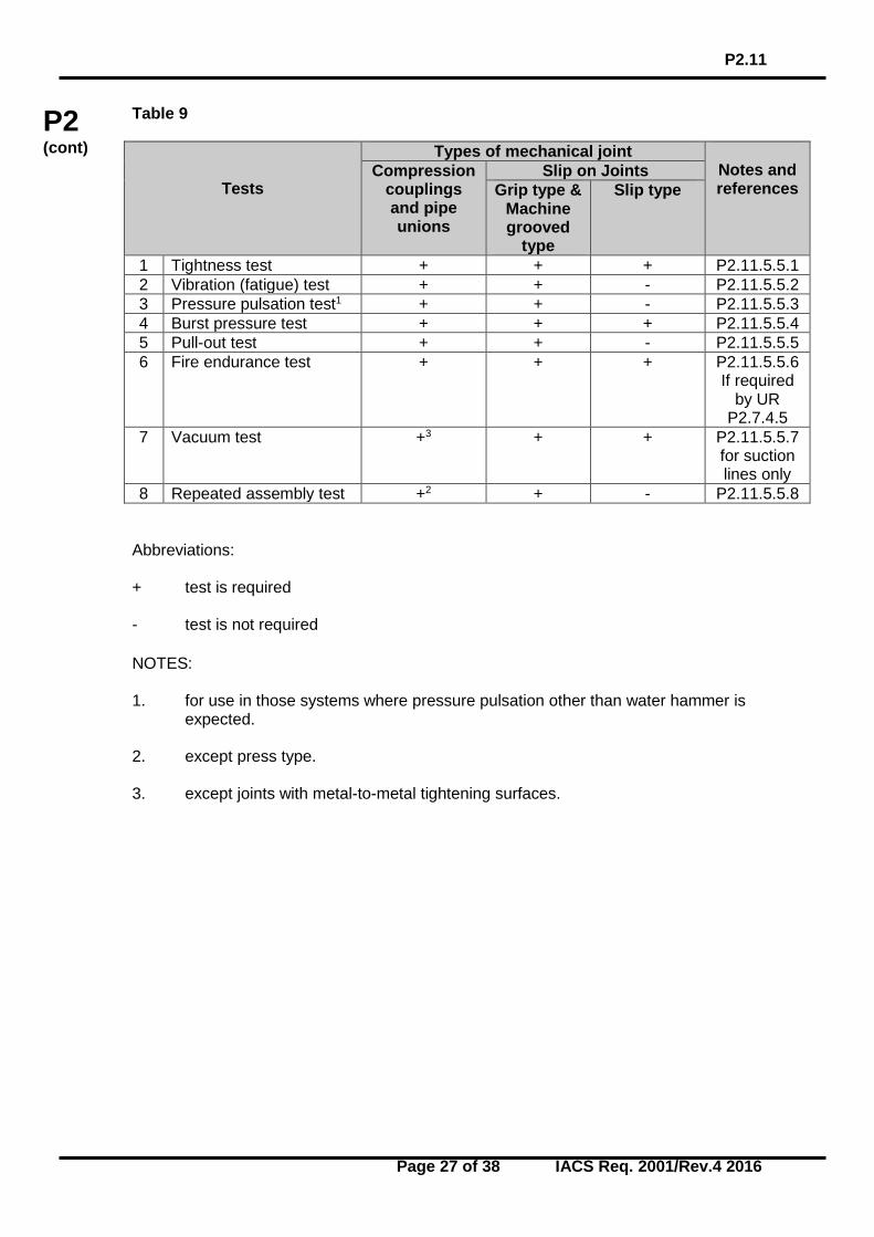
Table 9
Tests
Types of mechanical joint Notes and references
Compression couplings and pipe unions
Slip on Joints Grip type &
Machine grooved
type
Slip type
1 Tightness test + + + P2.11.5.5.1 2 Vibration (fatigue) test + + - P2.11.5.5.2 3 Pressure pulsation test1 + + - P2.11.5.5.3 4 Burst pressure test + + + P2.11.5.5.4 5 Pull-out test + + - P2.11.5.5.5 6 Fire endurance test
+ + + P2.11.5.5.6
If required by UR
P2.7.4.5 7 Vacuum test
+3 + + P2.11.5.5.7
for suction lines only
8 Repeated assembly test +2 + - P2.11.5.5.8 Abbreviations: + test is required - test is not required NOTES: 1. for use in those systems where pressure pulsation other than water hammer is
expected. 2. except press type. 3. except joints with metal-to-metal tightening surfaces.
P2.11
Page 28 of 38 IACS Req. 2001/Rev.4 2016
P2 (cont)
P2.11.5.3 Mechanical Joint Assembly Assembly of mechanical joints should consist of components selected in accordance with P2.11.5.2 and the pipe sizes appropriate to the design of the joints. Where pipe material would effect the performance of mechanical joints, the selection of joints for testing is to take the pipe material into consideration. Where not specified, the length of pipes to be connected by means of the joint to be tested is to be at least five times the pipe diameter. Before assembling the joint, conformity of components to the design requirements, is to be verified. In all cases the assembly of the joint shall be carried out only according to the manufacturer’s instructions. No adjustment operations on the joint assembly, other than that specified by the manufacturer, are permitted during the test. P2.11.5.4 Test Results Acceptance Criteria Where a mechanical joint assembly does not pass all or any part of the tests in Table 9, two assemblies of the same size and type that failed are to be tested and only those tests which the mechanical joint assembly failed in the first instance, are to be repeated. In the event where one of the assemblies fails the second test, that size and type of assembly is to be considered unacceptable. The methods and results of each test are to be recorded and reproduced as and when required. P2.11.5.5 Methods of tests .1 Tightness test In order to ensure correct assembly and tightness of the joints, all mechanical joints are to be subjected to a tightness test, as follows. a) The mechanical joint assembly test specimen is to be connected to the pipe or tubing
in accordance with the requirements of P2.11.5.3 and the manufacturer’s instructions, filled with test fluid and de-aerated.
Mechanical joints assemblies intended for use in rigid connections of pipe lengths, are not to be longitudinally restrained.
The pressure inside the joint assembly is to be slowly increased to 1.5 times the design pressure. This test pressure is to be retained for a minimum period of 5 minutes.
In the event of a drop in pressure or visible leakage, the test (including fire test) is to be repeated for two further specimens.
If during the repeat test one test piece fails, the coupling is regarded as having failed. An alternative tightness test procedure, such as a pneumatic test, may be accepted. b) For compression couplings a static gas pressure test is to be carried out to
demonstrate the integrity of the mechanical joints assembly for tightness under the
P2.11
Page 29 of 38 IACS Req. 2001/Rev.4 2016
P2 (cont)
influence of gaseous media. The pressure is to be raised to maximum pressure or 70 bar whichever is less.
c) Where the tightness test is carried out using gaseous media as permitted in (a) above,
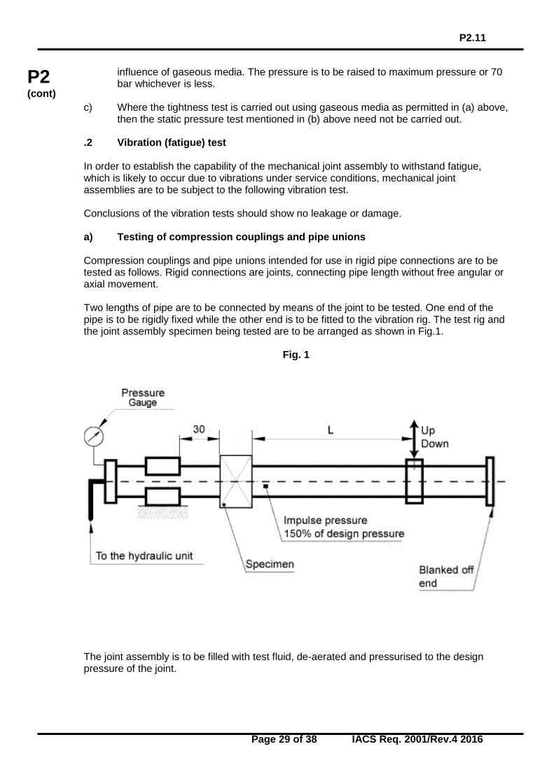
then the static pressure test mentioned in (b) above need not be carried out. .2 Vibration (fatigue) test In order to establish the capability of the mechanical joint assembly to withstand fatigue, which is likely to occur due to vibrations under service conditions, mechanical joint assemblies are to be subject to the following vibration test. Conclusions of the vibration tests should show no leakage or damage. a) Testing of compression couplings and pipe unions Compression couplings and pipe unions intended for use in rigid pipe connections are to be tested as follows. Rigid connections are joints, connecting pipe length without free angular or axial movement. Two lengths of pipe are to be connected by means of the joint to be tested. One end of the pipe is to be rigidly fixed while the other end is to be fitted to the vibration rig. The test rig and the joint assembly specimen being tested are to be arranged as shown in Fig.1.
Fig. 1
The joint assembly is to be filled with test fluid, de-aerated and pressurised to the design pressure of the joint.
P2.11
Page 30 of 38 IACS Req. 2001/Rev.4 2016
P2 (cont)
Pressure during the test is to be monitored. In the event of a drop in the pressure and visible leakage the test is to be repeated as described in P2.11.5.4. Visual examination of the joint assembly is to be carried out. Re-tightening may be accepted once during the first 1000 cycles. Vibration amplitude is to be within 5% of the value calculated from the following formula:
DELSA
××××
=32 2
where:
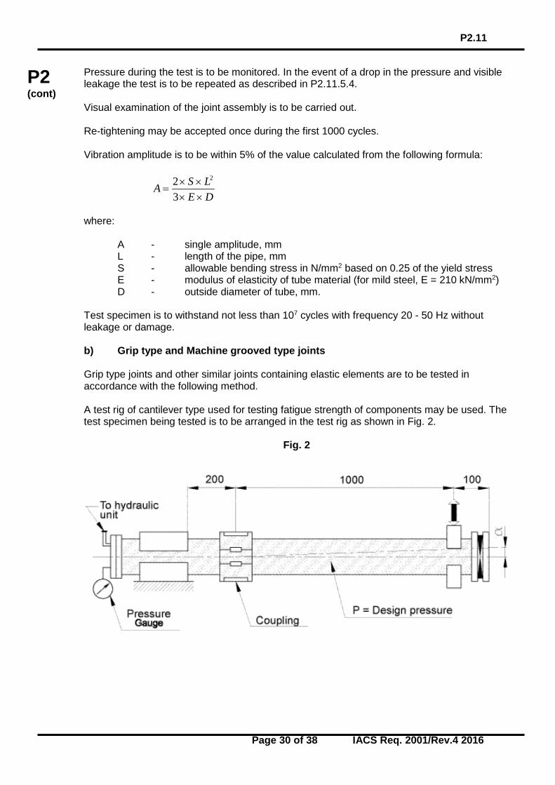
A - single amplitude, mm L - length of the pipe, mm S - allowable bending stress in N/mm2 based on 0.25 of the yield stress E - modulus of elasticity of tube material (for mild steel, E = 210 kN/mm2) D - outside diameter of tube, mm. Test specimen is to withstand not less than 107 cycles with frequency 20 - 50 Hz without leakage or damage. b) Grip type and Machine grooved type joints Grip type joints and other similar joints containing elastic elements are to be tested in accordance with the following method. A test rig of cantilever type used for testing fatigue strength of components may be used. The test specimen being tested is to be arranged in the test rig as shown in Fig. 2.
Fig. 2
P2.11
Page 31 of 38 IACS Req. 2001/Rev.4 2016
P2 (cont)
Two lengths of pipes are to be connected by means of joint assembly specimen to be tested. One end of the pipe is to be rigidly fixed while the other end is to be fitted to the vibrating element on the rig. The length of pipe connected to the fixed end should be kept as short as possible and in no case exceed 200 mm. Mechanical joint assemblies are not to be longitudinally restrained. The assembly is to be filled with test fluid, de-aerated and pressurized to the design pressure of the joint. Preliminary angle of deflection of pipe axis is to be equal to the maximum angle of deflection, recommended by the manufacturer. The amplitude is to be measured at 1m distance from the center line of the joint assembly at free pipe end connected to the rotating element of the rig. (See Fig. 2) Parameters of testing are to be as indicated below and to be carried out on the same assembly:
Number of cycles Amplitude, mm Frequency, Hz
3·106
± 0.06
100
3·106
± 0.5
45
3·106
± 1.5
10
Pressure during the test is to be monitored. In the event of a drop in the pressure and visual signs of leakage the test is to be repeated as described in P2.11.5.4. Visual examination of the joint assembly is to be carried out for signs of damage which may eventually cause leakage. .3 Pressure pulsation test In order to determine capability of mechanical joint assembly to withstand pressure pulsation likely to occur during working conditions, joint assemblies intended for use in rigid connections of pipe lengths, are to be tested in accordance with the following method. The mechanical joint test specimen for carrying out this test may be the same as that used in the test in P2.11.5.5.1 (a) provided it passed that test. The vibration test in P2.11.5.5.2 and the pressure pulsation test are to be carried out simultaneously for compression couplings and pipe unions. The mechanical joint test specimen is to be connected to a pressure source capable of generating pressure pulses of magnitude as shown in Fig 3.
P2.11
Page 32 of 38 IACS Req. 2001/Rev.4 2016
P2 (cont)
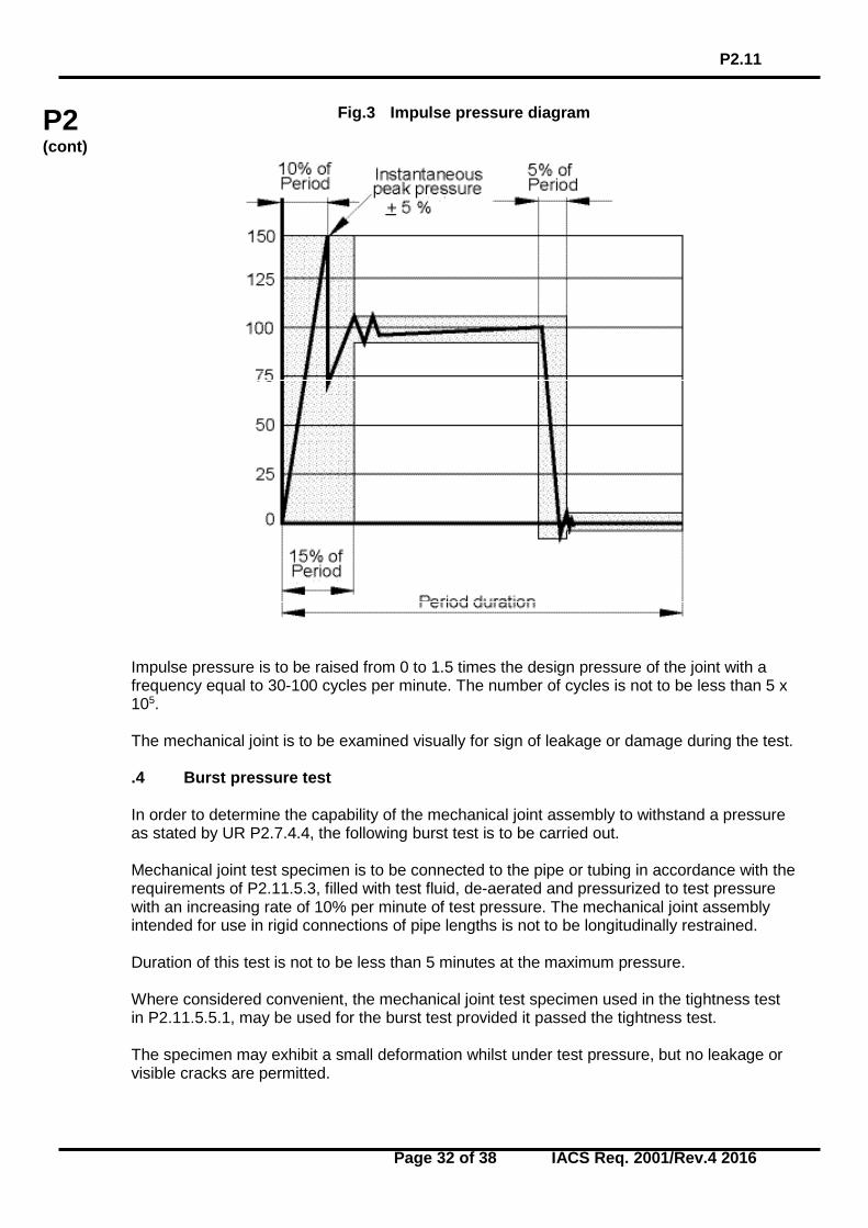
Fig.3 Impulse pressure diagram
Impulse pressure is to be raised from 0 to 1.5 times the design pressure of the joint with a frequency equal to 30-100 cycles per minute. The number of cycles is not to be less than 5 x 10⁵. The mechanical joint is to be examined visually for sign of leakage or damage during the test. .4 Burst pressure test In order to determine the capability of the mechanical joint assembly to withstand a pressure as stated by UR P2.7.4.4, the following burst test is to be carried out. Mechanical joint test specimen is to be connected to the pipe or tubing in accordance with the requirements of P2.11.5.3, filled with test fluid, de-aerated and pressurized to test pressure with an increasing rate of 10% per minute of test pressure. The mechanical joint assembly intended for use in rigid connections of pipe lengths is not to be longitudinally restrained. Duration of this test is not to be less than 5 minutes at the maximum pressure. Where considered convenient, the mechanical joint test specimen used in the tightness test in P2.11.5.5.1, may be used for the burst test provided it passed the tightness test. The specimen may exhibit a small deformation whilst under test pressure, but no leakage or visible cracks are permitted.
P2.11
Page 33 of 38 IACS Req. 2001/Rev.4 2016
P2 (cont)
.5 Pull-out test In order to determine the ability of a mechanical joint assembly to withstand the axial loading likely to be encountered in service without the connecting pipe becoming detached, following pull-out test is to be carried out. Pipes of suitable length are to be fitted to each end of the mechanical joint assembly test specimen. The test specimen is to be pressurized to design pressure. When pressure is attained, an external axial load is to be imposed with a value calculated using the following formula:
pDL ..4
2π=
where:
D - pipe outside diameter, mm p - design pressure, N/mm2
L - applied axial load, N The pressure and axial load are to be maintained for a period of 5 minutes. During the test, pressure is to be monitored and relative movement between the joint assembly and the pipe measured. The mechanical joint assembly is to be visually examined for drop in pressure and signs of leakage or damage. There is to be no movement between the mechanical joint assembly and the connecting pipes. .6 Fire endurance test In order to establish capability of the mechanical joints to withstand effects of fire which may be encountered in service, mechanical joints are to be subjected to a fire endurance test. The fire endurance test is to be conducted on the selected test specimens as per the following standards. (a) ISO 19921: 2005(E): Ships and marine technology – Fire resistance of metallic pipe components with resilient and elastomeric seals – Test methods (b) ISO 19922: 2005(E): Ships and marine technology – Fire resistance of metallic pipe components with resilient and elastomeric seals – Requirements imposed on the test bench. Clarifications to the standard requirements: 1. If the fire test is conducted with circulating water at a pressure different from the design pressure of the joint (however of at least 5 bar) the subsequent pressure test is to be carried out to twice the design pressure. 2. A selection of representative nominal bores may be tested in order to evaluate the fire resistance of a series or range of mechanical joints of the same design. When a mechanical joint of a given nominal bore (Dn) is so tested then other

P2.11
Page 34 of 38 IACS Req. 2001/Rev.4 2016
P2 (cont)
mechanical joints falling in the range Dn to 2xDn (both inclusive) are considered accepted. 3. Alternative test methods and/or test procedures considered to be at least equivalent may be accepted at the discretion of the Classification Society in cases where the test pieces are too large for the test bench and cannot be completely enclosed by the flames. 4. Thermal insulation materials applied on couplings are to be non-combustible in dry condition and when subjected to oil spray. A non-combustibility test according to ISO 1182 is to be carried out. .7 Vacuum test In order to establish the capability of the mechanical joint assembly to withstand internal pressures below atmospheric, similar to the conditions likely to be encountered under service conditions, the following vacuum test is to be carried out. The mechanical joint assembly is to be connected to a vacuum pump and subjected to a pressure of 170 mbar absolute. Once this pressure is stabilized, the specimen under test is to be isolated from the vacuum pump and the pressure is to be maintained for a period of 5 minutes. No internal pressure rise is permitted. .8 Repeated assembly test The mechanical joint test specimen is to be dismantled and reassembled 10 times in accordance with manufacturer’s instructions and then subjected to a tightness test as defined in P2.11.5.5.1.
End of Section
P2.12
Page 35 of 38 IACS Req. 2005/Rev.2 2016
P2 (cont)
P2.12 Flexible Hoses (Jan 2005) (Rev.1 Aug 2007) (Corr.1 Jan 2013) (Rev.2 Mar 2016) P2.12.1 Definition P2.12.1.1 Flexible hose assembly – short length of metallic or non-metallic hose normally with prefabricated end fittings ready for installation. P2.12.2 Scope P2.12.2.1 The requirements 2.12.3 to 2.12.6 apply to flexible hoses of metallic or non-metallic material intended for a permanent connection between a fixed piping system and items of machinery. The requirements may also be applied to temporary connected flexible hoses or hoses of portable equipment. P2.12.2.2 Flexible hose assemblies as defined in 2.12.1.1 may be accepted for use in oil fuel, lubricating, hydraulic and thermal oil systems, fresh water and sea water cooling systems, compressed air systems, bilge and ballast systems, and Class III steam systems where they comply with 2.12.3 to 2.12.6. Flexible hoses in high pressure fuel oil injection systems are not to be accepted. P2.12.2.3 These requirements for flexible hose assemblies are not applicable to hoses intended to be used in fixed fire extinguishing systems. P2.12.3 Design and construction P2.12.3.1 Flexible hoses are to be designed and constructed in accordance with recognised National or International standards acceptable to the Classification Society. Flexible hoses constructed of rubber materials and intended for use in bilge, ballast, compressed air, oil fuel, lubricating, hydraulic and thermal oil systems are to incorporate a single, double or more, closely woven integral wire braid or other suitable material reinforcement. Flexible hoses of plastics materials for the same purposes, such as Teflon or Nylon, which are unable to be reinforced by incorporating closely woven integral wire braid are to have suitable material reinforcement as far as practicable. Where rubber or plastics materials hoses are to be used in oil supply lines to burners, the hoses are to have external wire braid protection in addition to the reinforcement mentioned above. Flexible hoses for use in steam systems are to be of metallic construction. Note: 1. Changes to the requirements of UR P2.12.3.1 introduced in Rev.1 are to be uniformly implemented by all IACS Societies from 1 July 2008. 2. Changes to the requirements of UR P2.12.3.5 introduced in Rev.2 are to be uniformly implemented by all IACS Societies from 1 January 2017.
P2.12
Page 36 of 38 IACS Req. 2005/Rev.2 2016
P2 (cont)
P2.12.3.2 Flexible hoses are to be complete with approved end fittings in accordance with manufacturer’s specification. The end connections that do not have a flange are to comply with P2.7.4 as applicable and each type of hose/fitting combination is to be subject to prototype testing to the same standard as that required by the hose with particular reference to pressure and impulse tests. P2.12.3.3 The use of hose clamps and similar types of end attachments is not acceptable for flexible hoses in piping systems for steam, flammable media, starting air systems or for sea water systems where failure may result in flooding. In other piping systems, the use of hose clamps may be accepted where the working pressure is less than 5 bar and provided there are double clamps at each end connection. P2.12.3.4 Flexible hose assemblies intended for installation in piping systems where pressure pulses and/or high levels of vibration are expected to occur in service, are to be designed for the maximum expected impulse peak pressure and forces due to vibration. The tests required by 2.12.5 are to take into consideration the maximum anticipated in-service pressures, vibration frequencies and forces due to installation. P2.12.3.5 Flexible hose assemblies constructed of non-metallic materials intended for installation in piping systems for flammable media and sea water systems where failure may result in flooding, are to be of fire-resistant type except in cases where such hoses are installed on open decks, as defined in SOLAS II-2/Reg. 9.2.3.3.2.2(10) and not used for fuel oil lines. Fire resistance is to be demonstrated by testing to ISO 15540 and ISO 15541. P2.12.3.6 Flexible hose assemblies are to be selected for the intended location and application taking into consideration ambient conditions, compatibility with fluids under working pressure and temperature conditions consistent with the manufacturer’s instructions and any requirements of the Classification Society. P2.12.4 Installation P2.12.4.1 In general, flexible hoses are to be limited to a length necessary to provide for relative movement between fixed and flexibly mounted items of machinery/equipment or systems. P2.12.4.2 Flexible hose assemblies are not to be installed where they may be subjected to torsion deformation (twisting) under normal operating conditions. P2.12.4.3 The number of flexible hoses, in piping systems mentioned in 2.12.2.2 is to be kept to minimum and to be limited for the purpose stated in 2.12.2.1. P2.12.4.4 Where flexible hoses are intended to be used in piping systems conveying flammable fluids that are in close proximity of heated surfaces the risk of ignition due to failure of the hose assembly and subsequent release of fluids is to be mitigated as far as practicable by the use of screens or other similar protection to the satisfaction of the Classification Society. P2.12.4.5 Flexible hoses are to be installed in clearly visible and readily accessible locations.
P2.12
Page 37 of 38 IACS Req. 2005/Rev.2 2016
P2 (cont)
P2.12.4.6 The installation of flexible hose assemblies is to be in accordance with the manufacturer’s instructions and use limitations with particular attention to the following: • Orientation • End connection support (where necessary) • Avoidance of hose contact that could cause rubbing and abrasion • Minimum bend radii P2.12.5 Tests P2.12.5.1 Acceptance of flexible hose assemblies is subject to satisfactory prototype testing. Prototype test programmes for flexible hose assembles are to be submitted by the manufacturer and are to be sufficiently detailed to demonstrate performance in accordance with the specified standards. P2.12.5.2 The tests are, as applicable, to be carried out on different nominal diameters of hose type complete with end fittings for pressure, burst, impulse resistance and fire resistance in accordance with the requirements of the relevant standard. The following standards are to be used as applicable. • ISO 6802 - Rubber and plastics hoses and hose assemblies with wire reinforcements
- Hydraulic impulse test with flexing. • ISO 6803 - Rubber or plastics hoses and hose assemblies – Hydraulic-pressure
impulse test without flexing. • ISO 15540 - Ships and marine technology - Fire resistance of hose assemblies - Test
methods. • ISO 15541 - Ships and marine technology - Fire resistance of hose assemblies -
Requirements for test bench. • ISO 10380 - Pipework - Corrugated metal hoses and hose assemblies. Other standards may be accepted where agreed by the classification society. P2.12.5.3 All flexible hose assemblies are to be satisfactorily prototype burst tested to an international standard* to demonstrate they are able to withstand a pressure not less than four times its design pressure without indication of failure or leakage. Note * The international standards, e.g. EN or SAE for burst testing of non-metallic hoses, require the pressure to be increased until burst without any holding period at 4 x MWP.
P2.12
Page 38 of 38 IACS Req. 2005/Rev.2 2016
P2 (cont)
P2.12.6 Marking P2.12.6.1 Flexible hoses are to be permanently marked by the manufacturer with the following details: • Hose manufacturer’s name or trademark; • Date of manufacture (month/year); • Designation type reference; • Nominal diameter; • Pressure rating; • Temperature rating. Where a flexible hose assembly is made up of items from different manufacturers, the components are to be clearly identified and traceable to evidence of prototype testing.
End of Document End of Section
P3
Page 1 of 5 IACS Req. 1991/Rev.4 2016
P3 (cont)
Air Pipe Closing Devices P3.1 General requirements Where air pipes are required by the Rules or Load Line Convention, 1966 to be fitted with automatic closing devices, they are to comply with the following: P3.2 Design P3.2.1 Air pipe automatic closing devices are to be so designed that they will withstand both ambient and working conditions, and be suitable for use at inclinations up to and including ± 400. P3.2.2 Air pipe automatic closing devices are to be constructed to allow inspection of the closure and the inside of the casing as well as changing the seals. P3.2.3 Efficient ball or float seating arrangements are to be provided for the closures. Bars, cage or other devices are to be provided to prevent the ball or float from contacting the inner chamber in its normal state and made in such a way that the ball or float is not damaged when subjected to water impact due to a tank being overfilled. P3.2.4 Air pipe automatic closing devices are to be self-draining. P3.2.5 The clear area through an air pipe closing device in the open position is to be at least equal to the area of the inlet. P3.2.6 An automatic closing device is to: a) Prevent the free entry of water into the tanks, b) Allow the passage of air or liquid to prevent excessive pressure or vacuum coming on the tank. P3.2.7 In the case of air pipe closing devices of the float type, suitable guides are to be provided to ensure unobstructed operation under all working conditions of heel and trim as specified in 3.2.1. P3.2.8 The maximum allowable tolerances for wall thickness of floats should not exceed ± 10% of thickness. Note: 1. Revision 3 of this UR is to be applied by IACS Societies to any air pipe closing device submitted for new or revised approval from 1 January 2014. 2. Revision 4 of this UR is to be applied by IACS Societies to any air pipe closing device
submitted for new or revised approval from 1 January 2017.
P3 (1991) (Corr.1 May 1998) (Rev.1 May 2001) (Corr.1 April 2002) (Rev.2 Mar 2004) (Rev.3 Nov 2012) (Rev.4 Jan 2016)
P3
Page 2 of 5 IACS Req. 1991/Rev.4 2016
P3 (cont)
P3.2.9 The inner and the outer chambers of an automatic air pipe head is to be of a minimum thickness of 6 mm. Where side covers are provided and their function is integral to providing functions of the closing device as outlined in P3.2.6, they shall have a minimum wall thickness of 6 mm. If the air pipe head can meet the tightness test in P3.4.1b without the side covers attached, then the side covers are not considered to be integral to the closing device, in which case a wall less than 6 mm can be acceptable for side covers. P3.3 Materials P3.3.1 Casings of air pipe closing devices are to be of approved metallic materials adequately protected against corrosion. P3.3.2 For galvanised steel air pipe heads, the zinc coating is to be applied by the hot method and the thickness is to be 70 to 100 microns. P3.3.3 For areas of the head susceptible to erosion (e.g. those parts directly subjected to ballast water impact when the tank is being pressed up, for example the inner chamber area above the air pipe, plus an overlap of 100 or more either side) an additional harder coating should be applied. This is to be an aluminium bearing epoxy, or other equivalent, coating, applied over the zinc. P3.3.4 Closures and seats made of non-metallic materials are to be compatible with the media intended to be carried in the tank and to seawater and suitable for operating at ambient temperatures between -250C and 850C. P3.4 Type Testing P3.4.1 Testing of Air Pipe Automatic Closing Devices Each type and size of air pipe automatic closing device is to be surveyed and type tested at the manufacturer’s works or other acceptable location according to the Classification Society’s practice. The minimum test requirements for an air pipe automatic closing device are to include the following: a) Determination of the Flow Characteristics. The flow characteristics of the air pipe closing device are to be determined. Measuring of the pressure drop versus rate of volume flow is to be carried out using water and with any intended flame or insect screens in place. b) Tightness test during immersion/emerging in water. An automatic closing device is to be subjected to a series of tightness tests involving not less than two (2) immersion cycles under each of the following conditions: i) The automatic closing device is to be submerged slightly below the water surface at a velocity of approximately 4 m/min. and then returned to the original position immediately. The quantity of leakage is to be recorded. ii) The automatic closing device is to be submerged to a point slightly below the surface of the water. The submerging velocity is to be approximately 8 m/min and the air pipe vent head is to remain submerged for not less than 5 minutes. The quantity of leakage shall be recorded.
P3
Page 3 of 5 IACS Req. 1991/Rev.4 2016
P3 (cont)
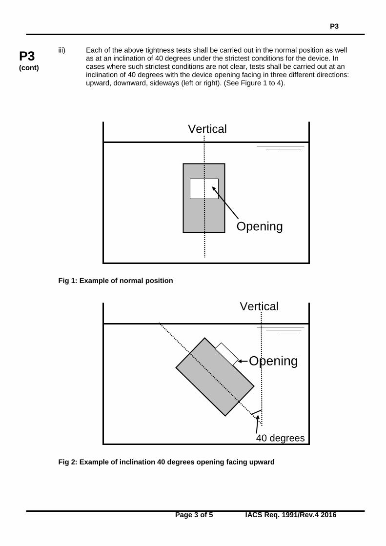
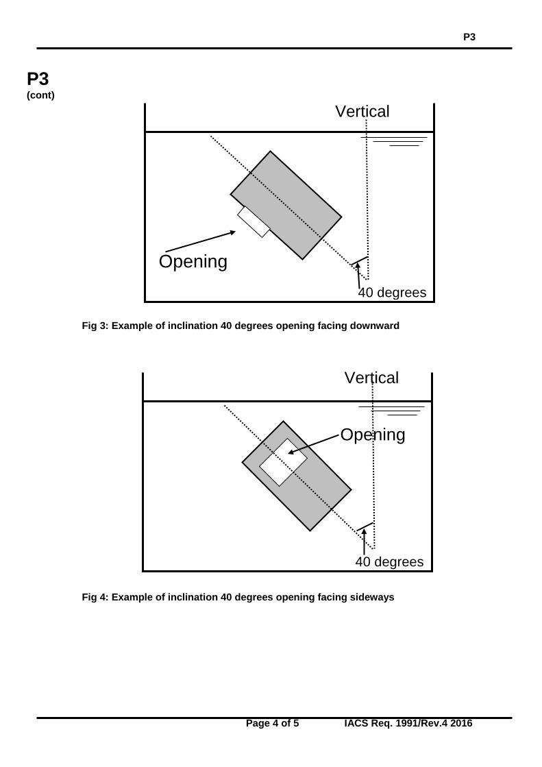
iii) Each of the above tightness tests shall be carried out in the normal position as well as at an inclination of 40 degrees under the strictest conditions for the device. In cases where such strictest conditions are not clear, tests shall be carried out at an inclination of 40 degrees with the device opening facing in three different directions: upward, downward, sideways (left or right). (See Figure 1 to 4). Fig 1: Example of normal position Fig 2: Example of inclination 40 degrees opening facing upward
Vertical
Opening
Vertical
Opening
40 degrees
P3
Page 4 of 5 IACS Req. 1991/Rev.4 2016
P3 (cont)
Fig 3: Example of inclination 40 degrees opening facing downward
Fig 4: Example of inclination 40 degrees opening facing sideways
Vertical
Vertical
Opening
40 degrees
Opening
40 degrees
P3
Page 5 of 5 IACS Req. 1991/Rev.4 2016
P3 (cont)
c) Discharge / Reverse flow test The air pipe head shall allow the passage of air to prevent excessive vacuum developing in the tank. A re verse flow test shall be performed. A vacuum pump or another suitable device shall be connected to the opening of the air pipe leading to the tank. The flow velocity shall be applied gradually at a constant rate until the float gets sucked and blocks the flow. The velocity at the point of blocking shall be recorded. 80% of the value recorded will be stated in the certificate.
The maximum allowable leakage per cycle shall not exceed 2 ml/mm of nominal diameter of inlet pipe during any individual test. P3.4.2 Testing of non-metallic Floats Impact and compression loading tests shall be carried out on the floats before and after pre-conditioning as follows: Test temperature OC Test condition
-25
20
85
Dry + + + After immerging in water + + + After immerging in fuel oil - + - Immerging in water and fuel oil is to be for at least 48 hours a) Impact Test The test may be conducted on a pendulum type testing machine. The floats shall be subjected to 5 impacts of 2.5 Nm each and shall not suffer permanent deformation, cracking or surface deterioration at this impact loading. Subsequently the floats shall be subjected to 5 impacts of 25 Nm each. At this impact energy level some localised surface damage at the impact point may occur. No permanent deformation or cracking of the floats shall appear. b) Compression Loading Test Compression tests shall be conducted with the floats mounted on a supporting ring of a diameter and bearing area corresponding to those of the float seating with which it is intended that float shall be used. For ball type float, loads shall be applied through a concave cap of the same internal radius as the test float and bearing on an area of the same diameter as the seating. For a disc type float, loads are to be applied through a disc of equal diameter as the float. A load of 350 kg shall be applied over one minute and maintained for 60 minutes. The deflection shall be measured at intervals of 10 minutes after attachment of the full load. The record of deflection against time is to show no continuing increase in deflection and, after release of the load, there shall be no permanent deflection. P3.4.3 Testing of Metallic Floats Tests shall be conducted in accordance with 3.4.2 a). The tests shall be carried out at room temperature and in the dry condition.
End of Document
P4
Page 1 of 12 IACS Req. 1996/Rev.4 2008
P4 (cont)
Production and Application of Plastic Pipes on Ships* P4.1 Terms and Conditions .1 “Plastic(s)” means both thermoplastic and thermosetting plastic materials with or without reinforcement, such as PVC and fibre reinforced plastics - FRP. .2 “Pipes/piping systems” means those made of plastic(s) and include the pipes, fittings, system joints, method of joining and any internal or external liners, coverings and coatings required to comply with the performance criteria. .3 “Joint” means joining pipes by adhesive bonding, laminating, welding, etc. .4 “Fittings” means bends, elbows, fabricated branch pieces etc. of plastic materials. .5 “Nominal pressure” means the maximum permissible working pressure which should be determined in accordance with the requirements in P 4.3.1. .6 “Design pressure” means the maximum working pressure which is expected under operation conditions or the highest set pressure of any safety valve or pressure relief device on the system, if fitted. .7 “Fire endurance” means the capability of piping to maintain its strength and integrity (i.e. capable of performing its intended function) for some predetermined period of time while exposed to fire. P4.2 Scope .1 These requirements are applicable to plastic pipes/piping systems on ships. .2 The requirements are not applicable to flexible pipes and hoses and mechanical couplings used in metallic piping systems. .3 Piping systems made of thermoplastic materials, such as polyethylene(PE), polypropylene(PP), polybutylene(PB) and intended for non-essential services are to meet the requirements of recognized standards and P4.5 and P4.6 of this UR. * This UR addresses the provisions of IMO Res. A.753(18). Note: 1. Rev.3 introduced new section P4.7. The requirements of UR P4.7 are to be uniformly implemented by all IACS Societies to any new plastic pipe submitted for approval from 1 January 2007 and to any existing plastic pipe from the date of the first renewal of approval after 1 January 2007. 2. Changes introduced in Rev. 4 of this UR P4.5 are to be uniformly implemented by IACS Members and Associates from 1 January 2010.
P4 (1996) (Corr. 1 1997) (Rev. 1 May 1998) (Rev. 2 July 1999) (Rev. 3 Feb 2005) (Rev. 4 Dec 2008)
P4
Page 2 of 12 IACS Req. 1996/Rev.4 2008
P4 (cont)
P4.3 General Requirements The specification of piping is to be in accordance with a recognised national or international standard acceptable to the Classification Society. In addition, the following requirements apply: 4.3.1 Strength .1 The strength of the pipes is to be determined by a hydrostatic test failure pressure of a pipe specimen under the standard conditions: atmospheric pressure equal to 100 kPa, relative humidity 30%, environmental and carried fluid temperature 298 kPa (25°C). .2 The strength of fittings and joints is to be not less than that of the pipes. .3 The nominal pressure is to be determined from the following conditions: (i) Internal Pressure For an internal pressure the following is to be taken whichever is smaller: Pn int ≤ Psth/4 or Pn int ≤ Plth/2.5 where Psth = short-term hydrostatic test failure pressure; Plth = long-term hydrostatic test failure pressure ( > 100,000 h) (ii) External Pressure For an external pressure: Pn ext ≤ Pcol/3 where Pcol - pipe collapse pressure. .4 In no case is the collapse pressure to be less than 3 bar. .5 The maximum working external pressure is a sum of the vacuum inside the pipe and a head of liquid acting on the outside of the pipe. .6 The maximum permissible working pressure is to be specified with due regard for maximum possible working temperatures in accordance with Manufacturer’s recommendations. 4.3.2 Axial Strength .1 The sum of the longitudinal stresses due to pressure, weight and other loads is not to exceed the allowable stress in the longitudinal direction. .2 In the case of fibre reinforced plastic pipes, the sum of the longitudinal stresses is not to exceed half of the nominal circumferential stress derived from the nominal internal pressure condition (see P 4.3.1).
P4
Page 3 of 12 IACS Req. 1996/Rev.4 2008
P4 (cont)
4.3.3 Impact Resistance .1 Plastic pipes and joints are to have a minimum resistance to impact in accordance with recognized national or international standards. .2 After the test the specimen is to be subjected to hydrostatic pressure equal to 2.5 times the design pressure for at least 1 hour. 4.3.4 Temperature .1 The permissable working temperature depending on the working pressure is to be in accordance with Manufacturer’s recommendations, but in each case it is to be at least 20ºC lower than the minimum heat distortion temperature of the pipe material, determined according to ISO 75 method A, or equivalent. .2 The minimum heat distortion temperature is to be not less than 80ºC. P4.4 Requirements for Pipes/Piping Systems Depending on Service and/or Locations 4.4.1 Fire endurance .1 Pipes and their associated fittings whose integrity is essential to the safety of ships are required to meet the minimum fire endurance requirements of Appendix 1 or 2, as applicable, of IMO Res A.753(18). .2 Depending on the capability of a piping system to maintain its strength and integrity, there exist three different levels of fire endurance for piping systems.
(i) Level 1. Piping having passed the fire endurance test specified in Appendix 1 of IMO Res. A.753(18) for a duration of a minimum of one hour without loss of integrity in the dry condition is considered to meet level 1 fire endurance standard (L1).
(ii) Level 2. Piping having passed the fire endurance test specified in Appendix 1 of
IMO Res. A.753(18) for a duration of a minimum of 30 minutes in the dry condition is considered to meet level 2 fire endurance standard (L2).
(iii) Level 3. Piping having passed the fire endurance test specified in Appendix 2 of
IMO Res. A.753 (18) for a duration of a minimum of 30 minutes in the wet condition is considered to meet level 3 fire endurance standard (L3).
.3 Permitted use of piping depending on fire endurance, location and piping system is given in Table 1 “Fire Endurance Requirement Matrix”.
P4
Page 4 of 12 IACS Req. 1996/Rev.4 2008
P4 (cont)
Table 1 Fire Endurance Requirements Matrix
N
Piping Systems
Location
A
B C D E F G H I J K
Machi-nery spaces of ca-tegory A
Other machi-nery spaces & pump rooms
Cargo pump rooms
Ro/Ro cargo holds
Other dry cargo holds
Cargo tanks
Fuel oil tanks
Ballast water tanks
Coffer- dams void spaces pipe tunnel & ducts
Accom-modation service & control spaces
Open decks
1
2
3
4
5
6
7
8
9
10
11
12
13
CARGO (FLAMMABLE CARGOES f.p.≤60°C) 1. Cargo lines NA NA L1 NA NA O NA O10 O NA L12
2. Crude Oil washing lines
NA NA L1 NA NA O NA O10 O NA L12
3. Vent lines NA NA NA NA NA O NA O10 O NA X INERT GAS 4. Water seal
effluent line NA NA O1 NA NA O1 O1 O1 O1 NA O
5. Scrubber effluent line
O1 O1 NA NA NA NA NA O1 O1 NA O
6. Main Line O O L1 NA NA NA NA NA O NA L16
7. Distribution lines NA NA L1 NA NA O NA NA O NA L12
FLAMMABLE LIQUIDS (f.p. > 60°C) 8. Cargo lines X X L1 X X NA3 O O10 O NA L1 9. Fuel oil X X L1 X X NA3 O O O L1 L1 10. Lubricating X X L1 X X NA NA NA O L1 L1 11. Hydraulic oil X X L1 X X O O O O L1 L1 SEAWATER1
12. Bilge main & branches
L17 L17 L1 X X NA O O O NA L1
13. Fire main & water spray
L1 L1 L1 X NA NA NA O O X L1
14. Foam system L1 L1 L1 NA NA NA NA NA O L1 L1
15. Sprinkler system L1 L1 L3 X NA NA NA O O L3 L3
16. Ballast L3 L3 L3 L3 X O10 O O O L2 L2
17. Cooling water, essential services
L3 L3 NA NA NA NA NA O O NA L2
18. Tank cleaning services fixed machines
NA NA L3 NA NA O NA O O NA L32
19. Non-essential systems
O O O O O NA O O O O O
P4
Page 5 of 12 IACS Req. 1996/Rev.4 2008
P4 (cont)
FRESHWATER 20. Cooling water
essential services
L3 L3 NA NA NA NA O O O L3 L3
21. Condensate return
L3 L3 L3 O O NA NA NA O O O
22. Non-essential systems
O O O O O NA O O O O O
SANITARY/ DRAINS/ SCUPPERS 23. Deck drains
(internal) L14 L14 NA L14 O NA O O O O O
24. Sanitary drains (internal)
O O NA O O NA O O O O O
25. Scuppers and discharges (overboard)
O1,8 O1,8 O1,8 O1,8 O1,8 O O O O O1,8 O
SOUNDING/AIR 26. Water tanks/ dry
spaces O O O O O O10 O O O O O
27. Oil Tanks (fp. > 60°C)
X X X X X X3 O O10 O X X
MISCELLANEOUS
28. Control air L15 L15 L15 L15 L15 NA O O O L15 L15
29. Service air (non essential)
O O O O O NA O O O O O
30. Brine O O NA O O NA NA NA O O O
31. Auxillary low pressure steam (≤ 7 bar)
L2 L2 O9 O9 O9 O O O O O9 O9
ABBREVIATIONS: L1 Fire endurance test (appendix 1) in dry conditions, 60 min L2 Fire endurance test (appendix 1) in dry conditions, 30 min L3 Fire endurance test (appendix 2) in wet conditions, 30 min O No fire endurance test required NA Not applicable X Metallic materials having a melting point greater than 925ºC FOOTNOTES: 1. Where non-metallic piping is used, remotely controlled valves to be provided at ship’s side
(valve is to be controlled from outside space). 2. Remote closing valves to be provided at the cargo tanks. 3. When cargo tanks contain flammable tanks with f.p. > 60°C, “O” may replace “NA” or “X”. 4. For drains serving only the space concerned, “O” may replace “L1”.
P4
Page 6 of 12 IACS Req. 1996/Rev.4 2008
P4 (cont)
5. When controlling functions are not required by statutory requirements or guidelines, “O” may
replace “L1”. 6. For pipe between machinery space and deck water seal, “O” may replace “L1”. 7. For passenger vessels, “X” is to replace “L1”. 8. Scuppers serving open decks in positions 1 and 2, as defined in regulation 13 of the
International Convention on Load Lines, 1966, should be “X” throughout unless fitted at the upper end with the means of closing capable of being operated from a position above the freeboard deck in order to prevent downflooding.
9. For essential services, such as fuel oil tank heating and ships whistle, “X” is to replace “O”. 10. For tankers where compliance with paragraph 3 (f) of regulation 13F of Annex I of MARPOL
73/78 is required, “NA” is to replace “O”. LOCATION DEFINITIONS: Location
Definition
A - Machinery spaces of category A Machinery spaces of category A as defined in SOLAS* regulation II-2/3.19.
B - Other machinery spaces and pump rooms Spaces, other than category A machinery spaces and cargo pump rooms, containing propulsion machinery, boilers, steam and internal combustion engines, generators and major electrical machinery, pumps, oil filling stations, refrigerating, stabilising, ventilation and air-conditioning machinery, and similar spaces and trunks to such spaces.
C - Cargo pump rooms Spaces containing cargo pumps and entrances and trunks to such spaces.
D - Ro-ro cargo holds Ro-ro cargo holds are ro-ro cargo spaces and special category spaces and special category spaces as defined in SOLAS* regulation II-2/3.14 and 3.18.
E - Other dry cargo holds All spaces other than ro-ro cargo holds used for non- liquid cargo and trunks to such spaces.
F - Cargo tanks All spaces used for liquid cargo and trunks to such spaces.
G - Fuel oil tanks All spaces used for fuel oil (excluding cargo tanks) and trunks to such spaces.
H - Ballast water tanks All spaces used for ballast water and trunks to such spaces.
I - Cofferdams, voids, etc. Cofferdams and voids are those empty spaces between two bulkheads separating two adjacent compartments.
P4
Page 7 of 12 IACS Req. 1996/Rev.4 2008
P4 (cont)
J - Accommodation, service Accommodation spaces, service spaces and control stations as defined in SOLAS* regulation II-2/3.10, 3.12, 3.22.
K - Open decks Open deck spaces as defined in SOLAS* regulation II-2/26.2.2. (5).
* SOLAS 74 as amended by the 1978 SOLAS Protocol and the 1981 and 1983 amendments (consolidated text). 4.4.2 Flame Spread .1 All pipes, except those fitted on open decks and within tanks, cofferdams, pipe tunnels, and ducts are to have low surface flame spread characteristics not exceeding average values listed in IMO Resolution A.653(16). .2 Surface flame spread characteristics are to be determined using the procedure given in IMO Resolution A.653(16) with regard to the modifications due to the curvilinear pipe surfaces as listed in Appendix 3 of IMO Resolution A.753(18). .3 Surface flame spread characteristics may also be determined using the text procedures given in ASTM D635, or in other national equivalent standards. 4.4.3 Fire Protection Coatings .1 Where a fire protective coating of pipes and fittings is necessary for achieving the fire endurance level required, it is to meet the following requirements:
(i) The pipes are generally to be delivered from the manufacturer with the protective coating on.
(ii) The fire protection properties of the coating are not to be diminished when
exposed to salt water, oil or bilge slops. It is to be demonstrated that the coating is resistant to products likely to come into contact with the piping.
(iii) In considering fire protection coatings, such characteristics as thermal expansion,
resistance against vibrations, and elasticity are to be taken into account. (iv) The fire protection coatings are to have sufficient resistance to impact to retain
their integrity. 4.4.4 Electrical Conductivity Where electrical conductivity is to be ensured, the resistance of the pipes and fittings is not to exceed 1 x 10⁵ Ohm/m. P4.5 Material approval and Quality Control During Manufacture .1 Prototypes of pipes and fittings are to be tested to determine short-term and long-term design strength, fire endurance and low surface flame spread characteristics (if applicable), electrical resistance (for electrically conductive pipes), impact resistance in accordance with this UR. .2 For prototype testing representative samples of pipes and fittings are to be selected to the satisfaction of the Classification Society.
P4
Page 8 of 12 IACS Req. 1996/Rev.4 2008
P4 (cont)
.3 The Manufacturer is to have quality system that meets ISO 9000 series standards or equivalent. The quality system is to consist of elements necessary to ensure that pipes and fittings are produced with consistent and uniform mechanical and physical properties. .4 Each pipe and fitting is to be tested by the Manufacturer at a hydrostatic pressure not less than 1.5 times the nominal pressure. Alternatively, for pipes and fittings not employing hand lay up techniques, the hydrostatic pressure test may be carried out in accordance with the hydrostatic testing requirements stipulated in the recognised national or international standard to which the pipe or fittings are manufactured, provided that there is an effective quality system in place. .5 Piping and fittings are to be permanently marked with identification. Identification is to include pressure ratings, the design standards that the pipe or fitting is manufactured in accordance with, and the material of which the pipe or fitting is made. .6 In case the Manufacturer does not have an approved quality system complying with ISO 9000 series or equivalent, pipes and fittings are to be tested in accordance with this UR to the satisfaction of the Classification Society’s surveyors for every batch of pipes. .7 Depending upon the intended application a Society may require the pressure testing of each pipe and/or fitting. P4.6 Installation 4.6.1 Supports .1 Selection and spacing of pipe supports in shipboard systems are to be determined as a function of allowable stresses and maximum deflection criteria. Support spacing is not to be greater than the pipe Manufacturer’s recommended spacing. The selection and spacing of pipe supports are to take into account pipe dimensions, mechanical and physical properties of the pipe material, mass of pipe and contained fluid, external pressure, operating temperature, thermal expansion effects, loads due to external forces, thrust forces, water hammer, vibrations, maximum accelerations to which the system may be subjected. Combination of loads is to be considered. .2 Each support is to evenly distribute the load of the pipe and its contents over the full width of the support. Measures are to be taken to minimize wear of the pipes where they contact the supports. .3 Heavy components in the piping system such as valves and expansion joints are to be independently supported. 4.6.2 Expansion .1 Suitable provision is to be made in each pipeline to allow for relative movement between pipes made of plastic and the steel structure, having due regard to:
(i) the difference in the coefficients of thermal expansion; (ii) deformations of the ship’s hull and its structure.
2. When calculating the thermal expansions, account is to be taken of the system working temperature and the temperature at which assembly is performed. 4.6.3 External Loads
P4
Page 9 of 12 IACS Req. 1996/Rev.4 2008
P4 (cont)
.1 When installing the piping, allowance is to be made for temporary point loads, where applicable. Such allowances are to include at least the force exerted by a load (person) of 100 kg at mid-span on any pipe of more than 100 mm nominal outside diameter. .2 Besides for providing adequate robustness for all piping including open-ended piping a minimum wall thickness, complying with 4.3.1, may be increased upon the demand of the Classification society taking into account the conditions encountered during service on board ships. .3 Pipes are to be protected from mechanical damage where necessary. 4.6.4 Strength of Connections .1 The strength of connections is to be not less than that of the piping system in which they are installed. .2 Pipes may be assembled using adhesive-bonded, welded, flanged or other joints. .3 Adhesives, when used for joint assembly, are to be suitable for providing a permanent seal between the pipes and fittings throughout the temperature and pressure range of the intended application. .4 Tightening of joints is to be performed in accordance with Manufacturer’s instructions. 4.6.5 Installation of Conductive Pipes .1 In piping systems for fluids with conductivity less than 1000 pico siemens per metre (pS/m) such as refined products and distillates use is to be made of conductive pipes. .2 Regardless of the fluid being conveyed, plastic piping is to be electrically conductive if the piping passes through a hazardous area. The resistance to earth from any point in the piping system is not to exceed 1 x 10⁶ Ohm. It is preferred that pipes and fittings be homogeneously conductive. Pipes and fittings having conductive layers are to be protected against a possibility of spark damage to the pipe wall. Satisfactory earthing is to be provided. .3 After completion of the installation, the resistance to earth is to be verified. Earthing wires are to be accessible for inspection. 4.6.6 Application of Fire Protection Coatings .1 Fire protection coatings are to be applied on the joints, where necessary for meeting the required fire endurance as for 4.4.3, after performing hydrostatic pressure tests of the piping system. .2 The fire protection coatings are to be applied in accordance with Manufacturer’s recommendations, using a procedure approved in each particular case. 4.6.7 Penetration of Divisions .1 Where plastic pipes pass through “A” or “B” class divisions, arrangements are to be made to ensure that the fire endurance is not impaired. These arrangements are to be tested in accordance with Recommendations for fire test procedures for “A”, “B” and “F” bulkheads (Resolution A.754(18) as amended).
P4
Page 10 of 12 IACS Req. 1996/Rev.4 2008
P4 (cont)
.2 When plastic pipes pass through watertight bulkheads or decks, the watertight integrity of the bulkhead or deck is to be maintained. .3 If the bulkhead or deck is also a fire division and destruction by fire of plastic pipes may cause the inflow of liquid from tanks, a metallic shut-off valve operable from above the freeboard deck should be fitted at the bulkhead or deck. 4.6.8 Control During Installation .1 Installation is to be in accordance with the Manufacturer’s guidelines. 2. Prior to commencing the work, joining techniques are to be approved by the Classification Society. 3. The tests and explanations specified in this UR are to be completed before shipboard piping installation commences. 4. The personnel performing this work are to be properly qualified and certified to the satisfaction of the Classification Society. 5. The procedure of making bonds is to include:
(i) materials used, (ii) tools and fixtures, (iii) joint preparation requirements, (iv) cure temperature, (v) dimensional requirements and tolerances, and (vi) tests acceptance criteria upon completion of the assembly.
.6 Any change in the bonding procedure which will affect the physical and mechanical properties of the joint is to require the procedure to be requalified. 4.6.9 Bonding Procedure Quality Testing .1 A test assembly is to be fabricated in accordance with the procedure to be qualified and it is to consist of at least one pipe-to-pipe joint and one pipe-to-fitting joint. .2 When the test assembly has been cured, it is to be subjected to a hydrostatic test pressure at a safety factor 2.5 times the design pressure of the test assembly, for not less than one hour. No leakage or separation of joints is allowed. The test is to be conducted so that the joint is loaded in both longitudinal and circumferential directions. .3 Selection of the pipes used for test assembly, is to be in accordance with the following:
(i) When the largest size to be joined is 200 mm nominal outside diameter, or smaller, the test assembly is to be the largest piping size to be joined.
(ii) When the largest size to be joined is greater than 200 mm nominal outside
diameter, the size of the test assembly is to be either 200 mm or 25% of the largest piping size to be joined, whichever is greater.
.4 When conducting performance qualifications, each bonder and each bonding operator are to make up test assemblies, the size and number of which are to be as required above.
P4
Page 11 of 12 IACS Req. 1996/Rev.4 2008
P4 (cont)
4.6.10 Testing After Installation on Board .1 Piping systems for essential services are to be subjected to a test pressure not less than 1.5 times the design pressure or 4 bar whichever is greater. .2 Piping systems for non-essential services are to be checked for leakage under operational conditions. .3 For piping required to be electrically conductive, earthing is to be checked, and random resistance testing is to be conducted. P4.7 Test Specification For Plastic Pipes 4.7.1 Scope Section P4.7 contains requirements for the Type Approval of plastic pipes. It is applicable to rigid pipes, pipe joints and fittings. 4.7.2 Documentation The following information for the plastic pipes, fittings and joints is to be submitted for consideration and approval: I. General Information
1. Pipe and fitting dimensions 2. Maximum internal and external working pressure 3. Working temperature range 4. Intended services and installation locations 5. The level of fire endurance 6. Electrically conductive 7. Intended fluids 8. Limits on flow rates 9. Serviceable life 10. Installation instructions 11. Details of marking
II. Drawings and supporting documentation:
1. Certificates and reports for relevant tests previously carried out. 2. Details of relevant standards. 3. All relevant design drawings, catalogues, data sheets, calculations and functional
descriptions. 4. Fully detailed sectional assembly drawings showing pipe, fittings and pipe
connections. III. Materials
1. The resin type. 2. Catalyst and accelerator types, and concentration employed in the case of
reinforced polyester resin pipes or hardeners where epoxide resins are employed. 3. A statement of all reinforcements employed where the reference number does not
identify the mass per unit area or the tex number of a roving used in a filament winding process, these are to be detailed.
P4
Page 12 of 12 IACS Req. 1996/Rev.4 2008
P4 (cont)
4. Full information regarding the type of gel-coat or thermoplastic liner employed during construction, as appropriate.
5. Cure/post-cure conditions. The cure and post cure temperatures and times employ resin/reinforcement ratio.
6. Winding angle and orientation. 4.7.3 Testing Testing is to demonstrate compliance of the pipes, fittings and joints for which Type Approval is sought with Unified Requirement P4. Pipes, joints and fittings are to be tested for compliance with the requirements of standards* acceptable to classification society. * For the lists of standards refer to IACS Recommendation 86.
End of Document
P5
Page 1 of 1 IACS Req. 2004
A2(cont)
Ballast Water Systems. Requirements onballast water exchange at sea.Deleted April 2011
P5(May2004)
End ofDocument

P6
Page 1 of 2 IACS Req. 2005/Rev.1 2015
P6 (cont)
Shell Type Exhaust Gas Heated Economizers That May Be Isolated From The Steam Plant System P6.1 Application This UR is applicable to shell type exhaust gas heated economizers that are intended to be operated in a flooded condition and that may be isolated from the steam plant system. All shell type exhaust gas heated economizers that may be isolated from the steam plant system in a flooded condition and which are fitted on board ships contracted for construction on or after 1 January 2007 are to comply with this UR. P6.2 Design and Construction Design and construction of shell type economizers are to pay particular attention to the welding, heat treatment and inspection arrangements at the tube plate connection to the shell. P6.3 Pressure Relief P6.3.1 Where a shell type economizer is capable of being isolated from the steam plant system, it is to be provided with at least one safety valve, and when it has a total heating surface of 50 m2 or more, it is to be provided with at least two safety valves in accordance with the classification society requirements. P6.3.2 To avoid the accumulation of condensate on the outlet side of safety valves, the discharge pipes and/or safety valve housings are to be fitted with drainage arrangements from the lowest part, directed with continuous fall to a position clear of the economizer where it will not pose threats to either personnel or machinery. No valves or cocks are to be fitted in the drainage arrangements. Note: 1. The requirements of P6 Rev.1 are to be uniformly implemented by IACS Societies for
shell type exhaust gas heated economizers:
i) when an application for certification of a shell type exhaust gas heated economizers is dated on or after 1 July 2016; or
ii) which are installed in new ships for which the date of contract for construction is on
or after 1 July 2016. 2. The “contracted for construction” date means the date on which the contract to build the
vessel is signed between the prospective owner and the shipbuilder. For further details regarding the date of “contract for construction”, refer to IACS Procedural Requirement (PR) No. 29.
P6 (May 2005) (Rev.1 June 2015)
P6
Page 2 of 2 IACS Req. 2005/Rev.1 2015
P6 (cont)
P6.3.3 Full details of the proposed arrangements to satisfy P6.3.1 to P6.3.2 are to be submitted for approval. P6.4 Pressure Indication Every shell type economizer is to be provided with a means of indicating the internal pressure. A means of indicating the internal pressure is to be located so that the pressure can be easily read from any position from which the pressure may be controlled. P6.5 Lagging Every shell type economizer is to be provided with removable lagging at the circumference of the tube end plates to enable ultrasonic examination of the tube plate to shell connection. P6.6 Feed Water Every economizer is to be provided with arrangements for pre-heating and de-aeration, addition of water treatment or combination thereof to control the quality of feed water to within the manufacturer’s recommendations. P6.7 Operating Instructions The manufacturer is to provide operating instructions for each economizer which is to include reference to: - Feed water treatment and sampling arrangements. - Operating temperatures – exhaust gas and feed water temperatures. - Operating pressure. - Inspection and cleaning procedures. - Records of maintenance and inspection. - The need to maintain adequate water flow through the economizer under all operating
conditions. - Periodical operational checks of the safety devices to be carried out by the operating
personnel and to be documented accordingly. - Procedures for using the exhaust gas economizer in the dry condition. - Procedures for maintenance and overhaul of safety valves.
End of Document