request for proposal euclid creek pump · pdf filecreek pump station/lakeshore boulevard...
TRANSCRIPT

Page 1 of 49
REQUEST FOR PROPOSAL
EUCLID CREEK PUMP STATION – LAKESHORE BOULEVARD
RELIEF SEWER
(ECPS/LBRS) WBS NO. CIP.CM.CSO.E.6.1212
June 2011
This Request for Proposal (RFP) is being sent to interested engineering firms for pre-design, design, bidding, construction and closeout engineering services for the Euclid Creek Pump Station/Lakeshore Boulevard Relief Sewer project. Proposals for providing these services will be received until the close of business (4:30 P.M.) on Friday, July 29, 2011. Proposals are to be delivered to the following name and address:
Julius Ciaccia, Executive Director Northeast Ohio Regional Sewer District 3900 Euclid Avenue Cleveland, OH 44115-2504
Attn: Kellie Rotunno, Director of Engineering and Construction Late submittals will not be considered.
A mandatory (for consultants that will submit as a prime) pre-proposal meeting will be held at 10:00 A.M. on Thursday, June 30, 2011 at the Northeast Ohio Regional Sewer District’s Environmental and Maintenance Services Center (EMSC), 4747 East 49th Street, Cuyahoga Heights, Ohio. Questions regarding this RFP shall be directed to Mr. Steve Janosko at the pre-proposal meeting or at other times by calling (216) 881-6600, ext. 6446 or e-mailing to [email protected]. The deadline for questions to be received in writing will be 7 calendar days prior to the proposal due date and time, to allow for a response to be provided in the last addendum if necessary.

Page 2 of 49
The RFP is organized as follows: SECTION 1.0 INTRODUCTION SECTION 2.0 SCOPE OF SERVICES SECTION 3.0 PROPOSAL CONTENT AND FORMAT SECTION 4.0 PROJECT SCHEDULE SECTION 5.0 EVALUATION AND SELECTION PROCESS SECTION 6.0 SUBMISSION OF PROPOSALS RFP list of Attachments The following attachments are included in this RFP. Attachment A Project Invoice Standards Attachment B Project Data Standards & Requirements Attachment C NEORSD MBE/WBE Policy Attachment D District Equal Employment Opportunity Form Attachment E Task and Hour Summary Form Attachment F NEORSD Cost Summary Form Attachment G NEORSD Non-Disclosure Agreement Attachment H Owner/Consultant Professional Services Agreement Attachment I NEORSD Anti-Terrorist Affidavit Attachment J NEORSD SWP3 Format Template RFP list of Exhibits The following exhibits are provided for informational purposes in DVD format at the pre-proposal meeting following the Consultant signing the Non-Disclosure Agreement: Exhibit I: Euclid Creek Pump Station Advanced Facilities Plan Report Exhibit II: Euclid Creek Pump Station Advanced Facilities Plan Drawings Exhibit III: Euclid Creek Pump Station & Lakeshore Interceptor Record
Drawings Exhibit IV Lakeshore Interceptor Manhole/Pipe Inspection & Photo Reports Exhibit V: Easterly CSO Phase II Facilities Plan Excerpts Exhibit VI: Euclid Creek Tunnel Shaft Site 4 Drawings Exhibit VII: Pump Station Design Standards

Page 3 of 49
1.0 INTRODUCTION 1.1 PROJECT BACKGROUND
In 1998, the Northeast Ohio Regional Sewer District (the District) undertook the Easterly CSO Phase II Facilities Plan to identify causes of and develop solutions for the activation of combined sewer overflows (CSOs) in the Easterly service district. A system of conveyance and storage facilities were identified to capture combined sewage for treatment in accordance with the USEPA National CSO Policy and the OEPA CSO Control Strategy. The first step taken by the District to implement the Easterly CSO plan was to advance the major components to preliminary design. This effort, called the Easterly Advanced Facilities Plan (AFP), has the following components:
• Storage tunnels • Tunnel Dewatering Pump Station • Consolidation sewers and Interceptor Relief • Euclid Creek Pump Station
The Easterly storage tunnel system will consist of four tunnels – Dugway, Doan, Shoreline and Euclid Creek. The 24-foot diameter Dugway and Euclid Creek rock tunnels are the deepest of the four tunnels. At the confluence of the Dugway and Euclid Creek storage tunnels on the Nine Mile site located immediately southeast of I-90 and west of E. 140th Street, the Tunnel Dewatering Pump Station (TDPS) will pump the captured CSO flows to the Easterly Wastewater Treatment Plant for full treatment. Supporting the tunnel storage projects are several consolidation conduits, numerous drop shafts and regulator modifications. The wet weather control components in the Easterly District located east of Euclid Creek are comprised of the Euclid Creek Pump Station (ECPS), and the Lakeshore Boulevard Relief Sewer (LBRS) which are the focus of this RFP. This pump station is located on the north side of Lakeshore Boulevard, immediately east of Euclid Creek and is in the Nottingham area of the City of Cleveland. The station, which was constructed in 1921, was identified to be upgraded and reconfigured due to age as well as operation and maintenance considerations. However, even after upgrade, the ECPS will still only convey the dry weather flow for this service area, and the Long Term CSO improvements for the ECPS service area will not be realized until the Lakeshore Boulevard Relief Sewer (LBRS) is constructed. This sewer will convey wet weather flow from the ECPS service area that exceeds the pump station peak rated capacity of 3.75 MGD to the Euclid Creek Storage Tunnel (ECT) until the 5-year, 6-hour storm flows are reached or the volume of the tunnel is exceeded. The LBRS will convey these controlled flows to the Euclid Creek Tunnel ECT-4 baffle drop shaft located on Lakeshore Boulevard west of Euclid Creek. The ECT and associated drop structure at ECT-4 are scheduled to be constructed in the next 4 years. Flows exceeding this rate or storage capacity would result in an overflow event from the LBRS-ECPS system via existing CSO 239 to Euclid Creek.

Page 4 of 49
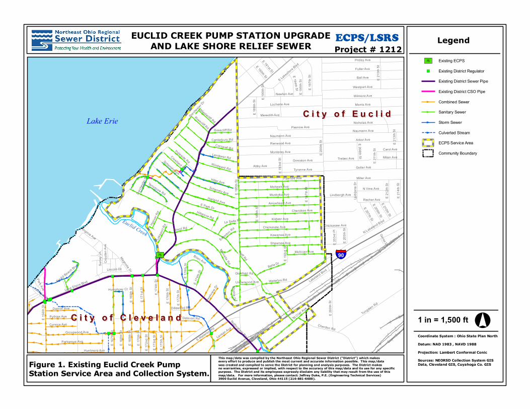
EXISTING ECPS AND LAKESHORE INTERCEPTOR SEWER SYSTEM CONDITIONS: The ECPS is located in the City of Cleveland on the east side of the Easterly District. The 470-acre service area, shown in Figure 1, is comprised mostly of residential properties with some commercial areas. Figure 2 shows the complete ECT alignment which carries flows to the Tunnel Dewatering Pump Station during wet weather events and sends the flow to the Easterly Wastewater Treatment Plant (EWWTP). Wastewater collected by local sewers, which are owned and maintained by the City of Cleveland, discharge into the District-owned Lakeshore Interceptor (LSI). Flow in the interceptor on the east side of Euclid Creek is discharged to the ECPS, which pumps the flow via a 12” ductile iron force main to a manhole on East 174th Street. This manhole is identified as MH 11073 on Sheet C-1 of the ECPS AFP drawings and SSMH 2974 on Sheet SP.400 of the Euclid Creek Tunnel bid documents. The outlet on this manhole is a 24” diameter gravity sewer. This 24” diameter sewer runs south and discharges to a No. 5 egg-shaped sewer at the intersection of East 174th Street and Nottingham Road (see SSMH 2685 on Sheet SP.400). The egg-shaped sewer (aka the LSI) runs west under Nottingham Road and then Lakeshore Boulevard. The ECPS/LSI collection system was originally designed as a separate sanitary system and has a limited capacity to convey wet weather flows. Flow monitoring and hydraulic modeling conducted as part of the Easterly CSO Phase II Facilities Plan indicated that the area is subject to high levels of inflow and infiltration with rainfall-runoff captures in the range of 15% to 40% which is more typical of a combined sewer system. Due to the high wet weather response, the ECPS/LSI collection system is subject to surcharging during small wet weather events and therefore prone to frequent surface and basement flooding problems. Flows in excess of the ECPS/LSI collection system capacities are relieved to Lake Erie at permitted CSO 208 and to Euclid Creek at permitted CSO 239. CSO 208 receives overflow from regulators L-21 and L-35 which are located north of Lakeshore Boulevard along Park Drive and Crestland Road, respectively. CSO 239 receives overflows from regulator L-39 which is located on the LSI just upstream of its connection to the ECPS wet well and acts as an emergency overflow to protect the EPCS from flooding. Overall, the collection system overflows via CSOs 208 and 239 approximately 40 times in a typical year based on previous CSO Phase II modeling results. These outfalls are the closest overflow points to the Euclid Beach recreation area. The exterior dimensions of the ECPS are 32 feet N-S and 26 feet E-W. The PS has two interior spaces - a 23 foot by 7 foot wet well and a 23 foot by 20.5 foot dry well. The dry well has a pump motor floor at grade, a partial intermediate grated level, and a basement pump floor. The pump floor is 24 feet below the motor floor. The wet well has a landing at grade and a floor 13 feet below the landing providing access to a screen that requires manual cleaning. Flow enters the ECPS wet well through its south wall via a 24” diameter sewer. Flow exits the pump station through its south wall via a 12” diameter force main. Photographs 1-1 and 1-2 depict the pump station from the south and north, respectively. Photographs 1-3 through 1-8 depict the interior of the pump station.

Page 5 of 49
The ECPS was originally equipped with two (2) cast-iron ejectors that pushed the sewage through the force main under the creek and into the downstream collection system. These abandoned ejectors are still in the pump station and shall be removed under this contract to obtain more working space. ECPS has undergone several mechanical upgrades, the most recent of which occurred in the 1990s. Pumping is currently handled by two Yeoman P4010 Model 8ML5 pumps dated August and September 1983. The vertical pumps have 8-inch diameter suction and discharge lines. Both have 870 RPM, 15 horsepower Toshiba motors that operate on a voltage of 220. The pumps are rated for 1,000 gpm at 34-feet of discharge head. The Lakeshore Interceptor is a 20” vitrified clay pipe increasing to 24” and 30” in the last two reaches upstream of the pump station. Depth from grade to sewer invert varies with ground elevation, and ranges from approximately 10 to 20 feet. Additional information on the Lakeshore Interceptor can be found in the exhibits to this RFP. SSMO has indicated that this sewer has a hydraulic issue as the LSI makes a 90 degree turn as it enters the ECPS. This hydraulic issue should be further investigated and potentially incorporated into the design plans to increase capacity and reduce grit build up for future dry weather flows. Geotechnical data is limited away from the ECT Shaft 4 site. A boring (EC-PS-101) performed on the ECPS site at Elev. 586 identified about 38 feet of overburden underlain by shale. The log for this boring is contained in the ECPS AFP Report. Several borings (including ECS-102, AP-009, AP-010) were performed near the location of ECT Shaft 4. These borings, at Elev. 602 to 603, identified about 55 to 60 feet of overburden underlain by shale.
")
")
")")
")
")
")
")
")
")")
")
")
")
")
")
")
")
[Ú
Euclid Creek
C i t y o f E u c l i dC i t y o f E u c l i d
C i t y o f C l e v e l a n dC i t y o f C l e v e l a n d
§̈¦90
Lake Shore Blvd
Neff Rd
St Clair Ave
Waterloo Rd
E Park Dr
Grovewood Ave
Lakeland Blvd
Ball Ave
N Lakeland Blvd
Nottingham Rd
Cherokee Ave
Miller Ave
Fuller Ave
Arbor Ave
Harland Ave
Shawnee Ave
Goller Ave
E 15
6th S
t
Morris Ave
Priday Ave
Kildeer Ave
Pasnow Ave
Pawnee Ave
E 17
6th S
t
Mohawk Ave
E 17
4th S
t
Locherie Ave
Meredith Ave
Wilmore Ave
Muskoka Ave
Chardon Rd
Newton Ave
Nicholas Ave
Kewanee Ave
Monterey Ave
Tungsten Rd
Renwood Ave
Westport Ave
E 18
8th S
t
E 16
8th S
t
E 16
7th S
t
Marcella Rd
Naumann Ave
E 17
7th S
t
Arrowhead Ave
Windward Rd
E 18
5th S
t
Parkgrove Ave
Hiller Ave
Landseer Rd
S Waterloo Rd
Abby Ave
Chickasaw Ave
Trebec Ave
E 17
1st S
t
Bel la Dr
E 16
9th S
t
E 20
0th S
t
Dorch
ester
Dr
Schenely Ave
Canterbury Rd
Dillewood Rd
E 19
5th S
t
Brazil Rd
E 19
7th S
t
E 21
2th S
t
E 17
0th S
t
Tyronne Ave
Mohican Ave
S Lakeshore B
lvd
Ormiston Ave
Lincoln Dr
Crestland Rd
Ingleside Rd
N Vine Ave
E 207th St
Surre
y Ln
Cornwall Rd Carol Ave
Milan Ave
Recher Ave
Damon Ave
Pythias Ave
Corsica Ave
E 21
4th S
t
Hillgrove Rd
E 17
8th S
t
E 179
th St
Rosecliff Rd
E 209th StHo
over
Rd
Glenfield Rd
Lindbergh Ave
Tarrymore Rd
Huntmere Ave
E 194th St
La Salle Rd
Lanken Ave
E 18
9th S
t
E 17
5th S
t
Delavan Rd
E 210th St
E 17
3rd S
t
E 17
2nd S
t
Ljublj
ana D
r
Magnolia Dr
E 191st St
E 190th St
E 208th St
Lakeside Pl
Park Ave
Lake
port R
d
Maplecliff Rd
E 21
3th S
t
E 20
5th S
t
Mozina Dr
E 19
3rd S
t E 20
3rd P
l
Edgerton Rd
Creekvi
ew Dr
Virginia Ave
Euclid Beach Blvd
Underwood Ave
Brian AveCroy
den A
ve
E 21
1th S
t
Humphrey Ct
Gorse Dr
Dorcheste
r Dr
E 19
3rd S
t
E 21
0th S
t
E 19
7th S
t
E 16
9th S
t
Schenely Ave
E 19
0th S
t
Chickasaw Ave
Rosecliff Rd
Naumann Ave
E 20
0th S
t
Lake Erie
This map/data was compiled by the Northeast Ohio Regional Sewer District (“District”) which makes every effort to produce and publish the most current and accurate information possible. This map/datawas created and compiled to serve the District for planning and analysis purposes. The District makesno warranties, expressed or implied, with respect to the accuracy of this map/data and its use for any specific purpose. The District and its employees expressly disclaim any liability that may result from the use of this map/data. For more information, please contact: Jeffrey Duke, P.E. (Engineering Technical Services) 3900 Euclid Avenue, Cleveland, Ohio 44115 (216-881-6600).
°1 in = 1,500 ft
Legend
Coordinate System : Ohio State Plan NorthDatum: NAD 1983 , NAVD 1988Projection: Lambert Conformal ConicSources: NEORSD Collection System GIS Data, Cleveland GIS, Cuyahoga Co. GIS
EUCLID CREEK PUMP STATION UPGRADEAND LAKE SHORE RELIEF SEWER ECPS/LSRS
Project # 1212[Ú Existing ECPS
") Existing District Regulator
Existing District Sewer Pipe
Existing District CSO Pipe
Combined Sewer
Sanitary Sewer
Storm Sewer
Culverted Stream
ECPS Service Area
Community Boundary
Figure 1. Existing Euclid Creek PumpStation Service Area and Collection System.

[Ú Euclid Creek
Nine Creek
C i t y o f E u c l i dC i t y o f E u c l i d
C i t y o f C l e v e l a n dC i t y o f C l e v e l a n d
C i t y o f C i t y o f B r a t e n a h lB r a t e n a h l
§̈¦90 Euclid Ave
Lake Shore Blvd
C hardon Rd
St Clair Ave
E 22
2nd S
t
Neff Rd
S Waterloo Rd
E 15
2nd S
t
E 14
0th S
t
Lakeland Blvd
Highland Rd
N Lakeland Blvd
Saranac Rd
Miller Ave
Coit Rd
E 21
5th S
t
Glenridge Rd
Grovewood Ave
E Park Dr
Ball Ave
Chardon Rd
London Rd
Wayside RdKipling Ave
Lake Shore Blvd
Tungsten Rd
Tracy AveNicholas Ave
Fuller Ave
Goller Ave
Arbor Ave
Cherokee Ave
Morris Ave
E 16
7th S
t
Priday Ave
Harland Ave
Shawnee Ave
Crystal Ave
Green Rd
Kildeer Ave
E 16
1st S
t
Waterloo Rd
Roseland Ave
E 210th St
Pasnow Ave
E 14
7th S
t
Wilmore Ave
E 17
6th S
t
Mohawk Ave
E 17
4th S
t
Locherie AveMeredith Ave
Westport Ave
Huntmere Ave
Darwin Ave
Muskoka Ave
Westropp Ave
Holmes Ave
Newton Ave
Kewanee Ave
Monterey AveRenwood Ave
Naumann Ave
Parkgrove Ave
E 14
9th S
t
E 14
1st S
t
E 14
6th S
tE
144th
St
E 191st St
Dille Rd
Saga
more
Dr
Marcella Rd
E 14
3rd S
t
E 17
7th S
t
Arrowhead Ave
E 15
0th S
t
E 18
5th S
t
Windward Rd
Avalon Rd
Catalpa Rd
Ivan Ave
E 18
7th S
t
Syracuse A
ve Nottingham Rd
E 193rd St
Hiller Ave
Landseer Rd
Argus Ave
E 173rd St
Arms Ave
Rudyard Rd
Trafalgar Ave
Cliffview Rd
E 195th St
E 148th St
Hillview Rd
Milton Ave
Hillto
p Rd
Abby Ave
Mandalay Ave
E 196th St
Chickasaw Ave
Burgess Rd
Upper Valley Dr
E 16
2nd S
t
North St
Kelso Ave
Ozark Ave
Ridpath Ave
Pontiac Dr
Trebec Ave
E 22
1st S
t
E 17
1st S
t
E 16
0th S
t
E 194th St
Bella Dr
E 16
9th S
t
Hadden RdJenne Ave
E 227th St
E 21
8th S
t
E 20
0th S
t
E 22
4th S
t
Roselan
d Rd
Darley Ave
Schenely Ave
Lucknow Ave
E 151st St
E 22
6th S
t
E 18
8th S
t
E 22
8th S
t
E 156th St
E 14
0th P
l
E 204th St
Major Dr
E 197th St
E 15
4th S
t
E 16
8th S
t
Brazil Rd
Thames Ave
E 22
0th S
t
Nathaniel RdBlackfoot Ave
Harms Rd
Tyronne Ave
Sylvia Ave
Bruce Ave
Firwood
Rd
E 13
8th P
l
Glen Russ Ln
Ormiston Ave
E 211th St
Lincoln Dr
Carol AveMilan Ave
Wickford Rd
E 157th StTrevitt C
ir
Ingleside Rd
N Vine Ave
Cham
p Dr
Coulter Ave
Diana Ave
E 192nd St
Recher Ave
E 172nd St
Damon AvePythias Ave
Beckford Ave
Hillcrest
Dr
Corsica Ave
Hillgrove Rd
Calcutta Ave
Linda Dr
Shore Acre
s Dr
Maydale Ave
E 166th St
Shasta C t
Othello Ave
Nye Rd
E 170th St
Whitcomb Rd
E 175th St
Tarrymore Rd
Natona Rd
E 142nd St
Grand B
lvd
Burbank Ct
Ardwell Dr
Lanken Ave
E 18
9th S
t
Cobalt Ave
E 16
3rd S
t
S Lakeshore Blvd
Brown St
Dalwood Dr
Cumberland Ave
Magnolia Dr
Beachvi
ew Dr
E 190th St
E 13
3rd S
t
E 15
5th S
t
Sene
ca R
d
Waldo Rd
Lakeshore Dr
Mc Elhatten Ave
Bonniewood Dr
Utopia Ave
Genesee Ave
Reese Rd
E 20
5th S
t
Lexington SqE
203rd
Pl
Jean Ave
Buffalo Ave
Edgerton Rd
Lakeside St
Crystal Ave
Fuller Ave
E 20
0th S
t
E 18
5th S
t
E 150th StE 149th St
S Lakeshore Blvd
E 16
9th S
t
Ivan Ave
Waterloo Rd
Nicholas Ave
E 18
5th S
t
Bal l Ave
E 17
3rd S
t
E 17
0th S
t
E 174th St
E 19
7th S
t
E 155th St
E 19
7th S
t
Naumann Ave
Tracy Ave
E 196th St
E 210th St
Priday AveE 191st St
Nottingham Rd
E 171st St
Lake Erie
This map/data was compiled by the Northeast Ohio Regional Sewer District (“District”) which makes every effort to produce and publish the most current and accurate information possible. This map/datawas created and compiled to serve the District for planning and analysis purposes. The District makesno warranties, expressed or implied, with respect to the accuracy of this map/data and its use for any specific purpose. The District and its employees expressly disclaim any liability that may result from the use of this map/data. For more information, please contact: Jeffrey Duke, P.E. (Engineering Technical Services) 3900 Euclid Avenue, Cleveland, Ohio 44115 (216-881-6600).
°1 in = 3,000 ft
Legend
Coordinate System : Ohio State Plan NorthDatum: NAD 1983 , NAVD 1988Projection: Lambert Conformal ConicSources: NEORSD Collection System GIS Data, Cleveland GIS, Cuyahoga Co. GIS
EUCLID CREEK PUMP STATION UPGRADEAND LAKE SHORE RELIEF SEWER ECPS/LSRS
Project # 1212[Ú Existing ECPS
Proposed LSRS
ECT (Under Construction)
ECPS Service Area
Community Boundary
Figure 2. Conceptual Alignment of ECTand LSRS.

Page 8 of 49
Photograph 1-1 Euclid Creek Pump Station from the South
Photograph 1-2 Euclid Creek Pump Station from the North

Page 9 of 49
Photograph 1-3 Pump Station - Wet Well
Photograph 1-4 Pump Station - Wet Well

Page 10 of 49
Photograph 1-5 Pump Station - Motor Level
Photograph 1-6 Pump Station - Motor Level

Page 11 of 49
Photograph 1-7 Pump Station - Old Ejectors to be Removed
Photograph 1-8 Pump Station – Suction Header, Pumps & Force Main

Page 12 of 49
PROPOSED ECPS PROJECT DESCRIPTION: The District’s LTCP for the ECPS service area recommended upgrading the ECPS in conjunction with the construction of the Lakeshore Boulevard Relief Sewer (LBRS) to alleviate the surcharging of the LSI. The preliminary configuration of this system is shown in Figure 3. Modifications of regulators L-21 and L-35 were also recommended to control overflows to CSO 208. Together, these projects are to provide CSO control up to the 5-year, 6-hour event while alleviating the surcharging of the LSI and most of the flooding problems in the ECPS service area. An additional intra-community relief sewer along Marcella Road/East 185th Street (MICRS) is also required to alleviate the remaining flooding problems to the 5-year, 6-hour event for the entire ECPS service area. The MICRS was not included in the District’s LTCP since the remaining flooding problems are due to conveyance issues in the City-owned local sewers and therefore, will remain the responsibility of the City. However LBRS shall be sized and hydraulically reviewed with the assumption that the MICRS will exist in the future as a flow input. Figure 4 illustrates the preliminary alignment of the LBRS and MICRS with respect to the ECPS site. Although the AFP calls for the ECPS project to entirely replace the existing structure, further evaluation has resulted in modifications to the proposed scope to include only upgrades to the pump station. The pump station equipment and configuration shall be upgraded to meet current codes and practices. This system shall also accommodate a diversion structure and system to control the flows as described. There is a hydraulic and maintenance concern in the LSI near the 90 degree turn as the sewer enters the station. This problem shall be evaluated during the design and corrected as part of the construction. The force main shall be inspected and refurbished and/or replaced based on the existing condition. Architectural, HVAC, Controls, and other apparent concerns shall be reviewed as part of this design and upgraded as necessary. Under proposed conditions, the existing LSI will remain in place and carry dry weather flows to the ECPS. The upgraded ECPS will continue to operate as a dry weather only pump station. Flows will continue to be pumped by the ECPS under Euclid Creek to the downstream portion of the LSI near Nottingham Road. The LBRS will capture and convey flows in excess of the existing LSI’s capacity, providing wet weather relief for surcharging and basement flooding up to the 5-year, 6-hour storm. It is anticipated that a peak 5-year, 6-hour design flow of 70.9 MGD (110 cfs) will be directed to the ECT via the LBRS. Flows exceeding the peak 5-year, 6-hour design flow will overflow to the Creek at CSO 239, thus requiring replacement or rehab of regulator L-39. The diversion structure that provides delivery of LBRS flows to the ECT at ECT-4 will require inflow control to protect the ECT and near surface conveyance systems from adverse hydraulic impacts. This will also allow for more flexibility in controlling the system since there would not be any uncontrolled inflows when the tunnel reaches its critical depths during filling. The diversion system would require inflow control gates consistent with those being constructed under the ECT project for shafts ECT-2, ECT-3 and ECT-5. The diversion configuration under this contract shall also have capabilities to screen large objects and settle grit prior to entering the ECT-4 drop shaft, similar to the other ECT system facilities.

Page 13 of 49
Regulators L-21 and L-35 will be modified to control the 5-year, 6-hour design event. Modifications of these regulators is expected to include upsizing the existing DWO sewers to convey the peak 5-year, 6-hour flows as recommended in the Easterly CSO Phase II Facilities Plan. The Contractor is expected to evaluate the impact of storm events greater than the 5-year, 6-hour event on the collection system based on the proposed regulator configurations. In addition, the Consultant will be expected to identify the level of hydraulic service associated with the ECPS service area. A schematic of the proposed work is shown in Figure 5. The ECPS AFP recommended two solids handling pumps with dry pit submersible motors. The pumps will be rated at 2,600 GPM at 45-feet design head with one operating and one in stand-by, similar to the current operation. Instrumentation and control will be designed in accordance with the District automation standards to provide remote monitoring of the facility. PLC and HMI programming shall be accomplished by the Contractor, based on descriptions of operation and other information provided by the designer in the bidding documents, and NEORSD programming standards and preferences. Electrical and Heating, Ventilating and Air Conditioning (HVAC) shall also brought up to code, resulting in the addition of continuous ventilation of the screenings area, the dry well and the Electrical/HVAC room. A natural gas generator will provide the required backup power supply. One critical element of the project is the work is in close proximity to residential properties, and careful consideration will be needed. This project is part of the Euclid Creek and Dugway Storage Tunnel system, identified as Control Measure Number 6, in Appendix 1 of the District’s CSO Long Term Control Plan Consent Decree dated December 2010. This decree requires “post construction monitoring” of completed control measures to ensure that performance criteria are being met as described in Appendix 2 of the consent decree. This includes monitoring flows for one year after completion of the control measure, updating of the hydraulic and hydrologic model parameters, if necessary, and simulating a typical series of rainfall events with the model to ensure that the frequency of overflows is within the performance criteria limits. As part of this project, the design of the completed facilities must ensure that flow monitors can be placed in all diversion and overflow facilities at a later date to accommodate the post-construction monitoring requirements. Appendix 3and 4 of the consent decree also describe the District’s requirements and opportunities relative to utilizing “green infrastructure” to provide additional CSO control beyond that provided by the control measures identified in Appendix 1,as well as to reduce the size of gray infrastructure by employing green infrastructure. Employment of green infrastructure on this project however is not subject to the requirements of Appendix 4. This project should consider potential benefits to the District in utilizing green infrastructure in accordance with Appendices 1, 2, and 3 of the consent decree. Consent decree documents can be accessed at the District’s website, www.neorsd.org/cso.php. 1.2 AVAILABLE INFORMATION If the Consultants request to examine relevant documents not provided as an exhibit to this RFP, they will be made available for examination at the District’s Administrative Office. To schedule an appointment to examine relevant District documents, contact Mr. Steve Janosko by calling 216-881-6600 Ext. 6446 or e-mailing at [email protected].

""
"
"
"
!
!
!
!!
!
!!
!!
!
!
!
!
!
!
!
!
!
!
!
!
!
!
!
!
!
!!
!
!
!
!
!
!
!
!
!
!
!
!
!
!
!
!!
!
!
!!
!
")
")
")
") ")
")
")
&-
&-
&-
&-
&-
!(B
Future Euclid Creek Tunnel
Nottingham - Main Branch
Lake S
hore Blvd
E. 1
74th
St
Future Euclid Creek Tunnel
Future EC
T-4
Consol
idation Sew
er
L-31 L-32Lake Shore Interceptor
DWIRS
DWIRSDWIRS
Propose
d Lake S
hore Reli
ef Sew
er (LS
RS)
Euclid Creek
CSO-239
CSO-209
24" E
xistin
g Lake
Shore
Intercep
tor
Existing ECPS
Future ECT Baffle Drop
Structure 4-1
Future ECTRegulator
Future ECTDiversion Stucture
Future ECTCSO 208 Tie-In Structure 4-6
L-39
Replace/Rehab L-39to Divert ECPS
Overflow to LSRSPrior to CSO 239
E. 1
71st
St
E. 1
69th
St
L-30
Future ECTRegulator
Marcella Rd
This map/data was compiled by the Northeast Ohio Regional Sewer District (“District”) which makes every effort to produce and publish the most current and accurate information possible. This map/datawas created and compiled to serve the District for planning and analysis purposes. The District makesno warranties, expressed or implied, with respect to the accuracy of this map/data and its use for any specific purpose. The District and its employees expressly disclaim any liability that may result from the use of this map/data. For more information, please contact: Jeffrey Duke, P.E. (Engineering Technical Services) 3900 Euclid Avenue, Cleveland, Ohio 44115 (216-881-6600).
°1 in = 200 ft
Legend
Coordinate System : Ohio State Plan NorthDatum: NAD 1983 , NAVD 1988Projection: Lambert Conformal ConicSources: NEORSD Collection System GIS Data, Cleveland GIS, Cuyahoga Co. GIS
EUCLID CREEK PUMP STATION UPGRADEAND LAKE SHORE RELIEF SEWER ECPS/LSRS
Project # 1212Proposed LSRS
! ! Existing & Proposed ECPS Force Main
!(B ECT-4 Baffle Drop (Under Construction)
ECT (Under Construction)
ECT Consolidation Sewer(Under Construction)
&- Existing CSO Permit Point
") Existing District Regulator
! Existing District Manhole
Existing District Sewer Pipe
Existing District CSO Pipe
Existing ECPS Building
Figure 3. Existing and ProposedConnectivity of ECPS and LSRS.

!!
")
")
")")
")
")
")
")
")
")")
")
")
")
")
")
")
")
&-
&-
&-
&-
&-
&-[Ú
!(B
Lake
Sho
re R
elief
Sewe
r (LS
RS)
Euclid Creek
L-21
L-35
L-39
Lake
Sho
re In
terc
epto
r (LS
I)
Marc
ella
Intra
-Com
mun
ity R
elie
f Sew
er (M
ICRS
)
Lake Shore Blvd
Neff RdE Park Dr
Harland Ave
Kildeer Ave
Pasnow Ave
E 18
8th S
t
Pawnee Ave
Mohawk Ave
Locherie Ave
Meredith Ave
Marcella Rd
Muskoka Ave
Newton Ave
Monterey Ave
Renwood Ave
Windward Rd
Kewanee Ave
Shawnee Ave
Naumann Ave
Cherokee Ave
Hiller Ave
Landseer Rd
Arrowhead Ave
Abby Ave
Chickasaw Ave
Bella Dr
Dorch
ester
Dr
Schenely Ave
Canterbury Rd
Brazil Rd
E 18
5th S
t
Lincoln Dr
Crestland Rd
Ingleside Rd
Surre
y Ln
Cornwall Rd
Hillgrove Rd
Tyronne Ave
Nottingham Rd
Rosecliff Rd
Waterloo Rd
E 17
8th S
t
Hoov
er Rd
Ormiston Ave
Mohican Ave
Sable
Rd
Tarrymore Rd
E 17
4th S
t
La Salle Rd
E 18
9th S
t
E 19
3rd S
t
E 179
th St
Cumberland Ave
Magnolia Dr
Lake
port R
d
Maplecliff Rd
N Lakeland Blvd
Sycamore St
Brist
ol Rd
Edgerton RdVirginia Ave
Brian Ave
E 19
7th S
t
E 19
0th S
t
Croyden Ave
E 19
3rd S
t
Schenely Ave
Dorcheste
r Dr
Rosecliff Rd
Magnolia Dr
E 19
7th S
t
Lake Erie
This map/data was compiled by the Northeast Ohio Regional Sewer District (“District”) which makes every effort to produce and publish the most current and accurate information possible. This map/datawas created and compiled to serve the District for planning and analysis purposes. The District makesno warranties, expressed or implied, with respect to the accuracy of this map/data and its use for any specific purpose. The District and its employees expressly disclaim any liability that may result from the use of this map/data. For more information, please contact: Jeffrey Duke, P.E. (Engineering Technical Services) 3900 Euclid Avenue, Cleveland, Ohio 44115 (216-881-6600).
°1 in = 1,000 ft
Legend
Coordinate System : Ohio State Plan NorthDatum: NAD 1983 , NAVD 1988Projection: Lambert Conformal ConicSources: NEORSD Collection System GIS Data, Cleveland GIS, Cuyahoga Co. GIS
EUCLID CREEK PUMP STATION UPGRADEAND LAKE SHORE RELIEF SEWER ECPS/LSRS
Project # 1212[Ú Existing ECPS (Proposed Upgrade)
Proposed LSRS
Proposed LSRS - DWO Upsized
Future MICRS (By Others)
! ! Existing & Proposed ECPS Force Main
!(B ECT-4 Baffle Drop (Under Construction)
&- Existing CSO Permit Point
") Existing District Regulator
Existing District Sewer Pipe
Existing District CSO Pipe
Combined Sewer
Sanitary Sewer
Storm Sewer
ECPS Service Area
Figure 4. Proposed LSRS and MICRSAlignments.

CS
O 2
39
EC
PS
EC
T-4
Ba
ffle
Dro
p
Sh
aft
(B
y O
the
rs)
CS
O 2
08
Mo
dif
y E
xist
ing
Re
gu
lato
r to
co
ntr
ol
5-y
ea
r, 6
-ho
ur
Mo
dif
y E
xist
ing
Re
gu
lato
r to
co
ntr
ol
5-y
ea
r, 6
-ho
ur
Re
ha
b p
um
p s
tati
on
to p
rov
ide
3.7
5 M
GD
cap
aci
ty
Flo
ws
up
to
th
e
5-y
ea
r, 6
-ho
ur
dir
ect
ed
to
EC
T
Re
ha
b/r
ep
lace
forc
e m
ain
Bu
lkh
ea
d
SW
O
L-3
9
L-3
5
L-2
1
EC
T-4
Re
ha
b E
CP
S
ov
erf
low
Up
size
DW
O
Pip
e A
s N
ee
de
d
Co
nsu
lta
nt’
s
Re
spo
nsi
bil
itie
s:
•D
esi
gn
LSR
S t
o r
ed
uce
surc
ha
rgin
g o
f LS
I d
uri
ng
5-y
r,
6-h
r e
ve
nt.
•E
va
lua
te h
yd
rau
lics
to
min
imiz
e L
SR
S
dia
me
ter,
de
pth
, an
d a
lig
nm
en
t.
•D
ete
rmin
e r
eq
uir
ed
nu
mb
er
of
con
ne
ctio
ns
be
twe
en
LSI
to
LSR
S.
•D
esi
gn
co
nn
ect
ion
ele
va
tio
n
to E
CT
-4 b
aff
le d
rop
sh
aft
to
rece
ive
pe
ak
flo
w o
f 7
5 M
GD
fro
m L
SR
S.
•D
esi
gn
re
gu
lato
r
con
fig
ura
tio
ns,
incl
ud
ing
DW
O
an
d S
WO
, a
t L-
21
an
d L
-35
.
Re
com
me
nd
ati
on
s o
f
ap
pro
pri
ate
lev
el o
f se
rvic
e f
or
ev
en
ts g
rea
ter
tha
n t
he
5-
ye
ar,
6-h
ou
r e
ve
nt
sha
ll b
e
pro
vid
ed
.
RE
DP
rop
ose
d In
fra
stru
ctu
re
GR
EE
NE
xist
ing
Infr
ast
ruct
ure
to B
e R
eh
ab
/
Up
gra
de
d
PU
RP
LEIn
fra
stru
ctu
re P
rov
ide
d
By
Oth
ers
BLU
EE
xist
ing
Infr
ast
ruct
ure
Dir
ect
ion
of
Dry
We
ath
er
Flo
w
Dir
ect
ion
of
Exc
ess
We
t
We
ath
er
Flo
w
Dir
ect
ion
of
Ov
erf
low
Page 17 of 49
2.0 SCOPE OF SERVICES
The scope of work for the Euclid Creek Pump Station project shall consist of, but not be limited to, the tasks as outlined below. Upon completion of the design, the project will be advertised for construction as per Ohio Revised Code (ORC) requirements. The District will not entertain design-build for the completion of this work. The tasks as described are the preferred project organization of the District. The Consultant should base its proposal on the described tasks. The Consultant should be familiar with the exhibits discussed in Section 1.0 and included in this RFP. Considerations of alternatives that the Consultant would like to present in the proposal are to be presented as requested in Section 2.2 of this RFP, ALTERNATES TO THE PROJECT. CONSULTANT’S RESPONSIBILITIES: The selected consultant shall provide all engineering services necessary to develop and produce a complete detailed design package that will culminate in a bidding package for the Euclid Creek Pump Station/Lakeshore Boulevard Relief Sewer (ECPS/LBRS) project. The Consultant shall work with Engineering & Construction Department and Operation & Maintenance Department personnel who will help define system needs and assist in achieving the District’s desired scope of work. The Consultant shall carefully consider the input by the District’s staff, but based on the Consultant’s own experience and ability, shall be solely responsible to provide a complete and workable design package in accordance with the requirements of the scope of work. The Consultant shall incorporate the use of the District’s SharePoint site electronic submissions and workflow processes for all Tasks of Work as directed by the District. The Consultant shall use the SharePoint site for, but not limited to, the following: electronic upload of documents for reference and/or file, invoicing, design schedules, budget transfers, construction submittals, Request for Information (RFIs), Contractor pay requests, construction changes, schedule reviews, etc. During the duration of the Contract the District may modify and/or add workflow processes and SharePoint usage, and the Consultant shall incorporate the modifications and additions into their work. Access to the SharePoint site and workflow processes and training will be provided by the District. The Consultant shall assume for their task and hour summary that two separate bid packages will be created for the ECPS retrofit and the LBRS system. DISTRICT’S RESPONSIBILITIES: The District will, at the selected firm’s request, provide information and material on file that is pertinent to the preparation of the plans and specifications. This may include plan and profile sheets of existing services, standard drawings, specifications, etc. The District will provide information on the requirements and standards for the project including the following:
1. Standard format and drafting procedures for construction drawings.

Page 18 of 49
2. Standard forms for bid documents: Legal Notice, Instructions to Bidders, General Terms and Conditions, Bid Forms, Agreement Forms, Division 1 Specifications and bond requirements.
3. Formats for specifications and other documents.
4. Standard construction drawings.
5. Project Management Templates
6. NEORSD automation standards
7. NEORSD Pump Station Standards and Preferences
2.1 SCOPE OF SERVICES FOR PROJECT
The scope of work for this project includes the following tasks.
2.1.1 Task 1: Pre-Design
All Task 1 deliverables shall be submitted in the following formats and quantities:
• 5 hard copies bound and indexed appropriately • 1 indexed PDF electronic copy • 1 original electronic application format copy
2.1.1.1 Task 1A: Project Management Plan
Within 30 days of the Notice-to-Proceed the Consultant shall provide a detailed Project Management Plan that includes critical processes and management activities that ensure compliance with the project design, schedule, and risk and budget requirements. Included in the management plan will be the following items:
• Team integration – discuss the project management team responsibilities, assigning of activities, and integration of the design team to meet project objectives and program standards.
• Budget and schedule management – include description of task tracking activities
and critical path earned value scheduling format and systems. Submit monthly cash flow projections, including utilization and cash flow for sub-consultants and MBE/WBEs, in a Primavera P6 cost loaded schedule.
• Progress reporting – include project management instructions for measuring
performance and reporting completion status including a look back, look forward and critical issue resolutions.

Page 19 of 49
• QA/QC – description of the project quality assurance and quality control systems
recommended to manage quality related problems and/or owner reviews of design deliverables and bid documents.
• MBE/WBE subcontracting plan – include the process description for analyzing
subcontracting work opportunities for minority/women businesses once the design elements are defined to a point where these work activities can be defined.
• Cost estimates – include confirmation that Consultant understands the cost
estimating guidelines and identification of software systems and process to develop the estimates.
• Risk management - include a description of the consultant’s risk management plan
considering all project related risks and mitigation measures to alleviate those risks. This should include confirmation that Consultant understands program management risk register requirements and method for developing and maintaining this register as a main design support tool.
2.1.1.2 Task 1B: Basis of Design Report
The Consultant shall prepare a Basis of Design Report for the ECPS/LBRS that summarizes the pre-design work activities and critical design decisions to support advancement of the project into detailed design. The design parameters for the selected option shall be described in the Basis of Design Report. This document may also support the independent Value Engineering session to be held following the 30% Design subtask if authorized by the District from the Allowance task. Pre-design sub-tasks 1C through 1M shall be developed by the Consultant to the appropriate level of detail for Basis of Design Report.
2.1.1.3 Task 1C: Pump Station Configuration and Sewer Alignment
Identify various configurations/locations for the pump station, Regulator L-39/CSO 239, the ECPS force main, routes/installation methods for the Lakeshore Boulevard Relief Sewer, and associated regulator modifications.
2.1.1.4 Task 1D: Construction Sequence and Methods
Identify the construction sequence and method(s) that would be suitable for the proposed pump station, Regulator L-39/CSO 239, the ECPS force main, routes/installation methods for the Lakeshore Boulevard Relief Sewer, and associated regulator modifications.
Page 20 of 49
2.1.1.5 Task 1E: Surveying
Perform surveying as necessary to complete the project scope and investigation for the proposed facilities. Identify all existing utilities both vertically and horizontally. Obtain sufficient surface elevation data along the alignment to ascertain the required depths of excavation. Identify public and private property, bridges, buildings, other structures, and water bodies that will impact or be impacted.
For the Basis of Design Report, the Consultant shall survey as described below: • Locate critical elevations and establish a reference benchmark circuit for all
construction.
• Perform all research and procure all information necessary to establish existing right-of-way, property, and existing easement lines.
• Perform spot survey checks to verify the accuracy of the topographic mapping.
Utility Tracking Form: In areas of expected excavation, the Consultant shall conduct an OUPS search and identify existing utility locations. The Consultant will be required to maintain a detailed utility tracking form to record and document all data collected with respect to line and grade conflicts as well as overhead constraints. All locations/elevations are to be referenced to the State Plane Coordinate System. 2.1.1.6 Task 1F: Permits and Easements
Identify permits required by public and private entities, including but not limited to the City of Cleveland, Army Corps of Engineers, and Ohio EPA (Permit to Install, SWPPP, NOI, etc.).
Also identify easements, rights of entry, license agreements and any other types of access agreements that will be required through public or private property. When developing schedules, take into account the time required to obtain such permits and property access rights.
2.1.1.7 Task 1G: Geotechnical Investigation
Soil borings and rock cores shall be obtained near the project facilities as necessary to assess the suitability and cost of the construction methods associated with each alternative. The number of borings and cores shall be as recommended by the Consultant. The Consultant shall also utilize existing geotechnical data as appropriate.
Consultant shall select and coordinate the services of a subcontractor to perform all soil
borings, rock corings, and pavement corings; take all soil and rock samples; install any necessary instrumentation; and provide all testing services required for the development of geotechnical reports. It will be the responsibility of the Consultant to

Page 21 of 49
ensure that the boring subcontractor properly notifies all affected parties and secures any needed permits prior to commencing work, fills all bore holes with grout upon completion of boring work, and restores each site to a condition equal to or better than that which was originally encountered. All boring locations must be photographed prior to commencing boring activities. Each photograph must be properly labeled with a minimum of the date, boring identification number, street address and city.
Photographs shall be bound and presented to the District. Filled or final core boxes shall be photographed prior to removal from the boring site. Soil samples taken from the borings shall be properly stored and preserved to prevent/minimize moisture change and shall be delivered to the District for storage upon analysis completion.
Consultant shall select and coordinate the services of a sub-consultant who specializes in geotechnical consulting to prepare preliminary and final geotechnical reports. 2.1.1.8 Task 1H: Hydraulic Analysis
The Consultant will be provided a copy of the official Easterly LTCP Model and associated support files for use in developing the ECPS/LBRS design. The model is in DHI Software’s MIKE URBAN 2009 Service Pack 5 software platform. The Consultant is strongly encouraged to use this version for the analysis and design. In the event that a later version is preferred or recommended by the Consultant, the Consultant is responsible for validating the model results generated by the recommended software version by demonstrating flows, HGLs, and volumes meet the performance criteria specified.
The Consultant is required to comply with the District’s CSO Model Standards and Protocols when editing/modifying the model that will be submitted back to the District as a deliverable. A copy of the District’s CSO Model Standards and Protocols will be provided at a later date to the awarded consultant. For the purposes of this proposal, the Consultant should assume that the model protocols will include receiving a copy of the Easterly Negotiated Plan master model to be used in developing a project specific “child” version design model that includes final design configurations and is delivered to the District upon completion of the design. . All changes to the model in creating the project specific design model must be clearly documented in the submission to the District. In addition, any changes to the design resulting from construction must be documented as part of the project close-out deliverables for purpose of future master model updates. All modeling effort for this project will be included in the base services. 2.1.1.9 Task 1I: Schedule
To the extent possible, outline the critical path for major design and construction tasks and the dependency on other factors of the design. Throughout the project, the Consultant must provide a critical path, cost-loaded schedule that meets the milestone requirements described in Section 4.0 of this RFP.

Page 22 of 49
2.1.1.10 Task 1J: Construction Cost Estimates
Consultant shall create and submit at the major milestones of 30%, 60%, 90% and Final, an estimate in accordance with the Association for the Advancement of Cost Engineering (AACE) International Recommended Practice 18R-97.
2.1.1.11 Task 1K: Coordination with Other Entities
Take into consideration all past, present and future work of other public and private entities. Some of the entities and projects for which coordination will be necessary are identified in Section 1.0 of this RFP; however, the Consultant should assume that coordination will not be limited to those entities and projects. 2.1.1.12 Task 1L: Community Impact Assessment
The Consultant shall prepare a Community Impact Assessment, with the intent of identifying potential short-term impacts to the community during construction, and long-term impacts that arise as a result of the installed asset. Impacts are considered to be both positive and negative in nature. The magnitude and complexity of the project will dictate the level of assessment performed by the Consultant. At this time, the Owner anticipates that a Level 3 Assessment would be required for the rehabilitation of the Euclid Creek Pump Station and the construction of the Lakeshore Boulevard Relief Sewer. Level 1 Assessments: Typically underground repairs and improvements to existing assets, in existing easements and right-of-ways, does not expand the footprint of the existing asset to a significant extent and construction is short-term (less than 6 months) in duration. Level 1 Assessments will typically focus on impacts to local residents (noise, dust, odors, loss of parking, access, inconvenience, etc.); impacts to businesses; places of worship; public agency (i.e. fire, police, schools, Rapid Transit Authority, refuse collection) services; vegetation, pedestrian and vehicular traffic patterns, etc. during construction.
Level 2 Assessments: Repairs and improvements that significantly expand beyond the footprint of the original asset, or expand the easement or right-of-way to include community areas not previously impacted by the installation of the original asset. Will also include new aboveground structures and projects of longer term duration (greater than 6 months). Level 2 Assessments will typically include all Level 1 Assessment requirements; however, may also include aesthetic impacts from aboveground structures; potential economic impacts to local businesses; long-term changes to traffic patterns, road
Page 23 of 49
degradation, changes in land use, emergency response and other impacts due to long-term construction, and changes or additions to permanent aboveground structures.
Level 3 Assessments: Typically new aboveground structures on “green field” sites where impacts to the community will be permanent from significantly altering the physical condition of the site. Level 3 Assessments may include requirements of Levels 1 and 2 Assessments as applicable; however, typically will include impacts to community socio-economic conditions; alter future land use plans, land valuations, require future security plans, and other more permanent changes to the community.
Deliverables: The Consultant will provide a level of specificity in the Assessment (specific names of business impacted, type of impact, term of impact, residential addresses, agencies, community profiles and other community entities impacted), so that the Assessment can be developed into an actionable Community Relations and Communication Plan by the Owner in support of the project. The Assessment will provide a general description of the impacted area, specific areas of impact and evaluate the level of impact to each entity impacted. The assessment will also include maps, drawings, study information, supporting documentation and references in support of the Public Impact Assessment. The Consultant’s Assessment will be provided to the Owner as a section within the (30%, 60%, 90% and Final) design phase submittals, as the Assessment evolves with additional site and public impact information. Elements of the Assessment may be included in the bid documents, at the Owner’s discretion.
Meetings: The consultant will be expected to attend both internal and external meetings in support of the project. These meetings may include; internal design reviews, contract reviews, Board meetings, internal informational meetings and public meetings. 2.1.1.13 Task 1M: Risk Analysis
Perform a risk analysis that identifies environmental risks, safety risks and economic risks. Identify short-term and long-term risks, including those risks associated with the period proceeding implementation of the construction, construction risks, and risks following implementation of the construction. Describe the consequences and likelihood of occurrence of each identified risk. Identify the means of mitigating the risks as well as the cost of mitigation. The risks and associated likelihood of occurrence as well as impact of occurrence will be summarized in a risk register. The risk register template will be provided by the District.

Page 24 of 49
2.1.2 Task 2: Design
The Consultant shall develop drawings and specifications and integrate the District’s Division 1 specification templates and Bid Booklet (including Instructions to Bidders, General Terms and Conditions, Special Conditions, Agreement) for the ECPS/LBRS project to produce a construction bid document suitable for competitive bidding purposes. The contract drawings will indicate the layout, plans, sections, and details of the Euclid Creek Pump Station and the associated sewer and site improvements.
All specifications shall be prepared with the CSI 2004 format. Page layout, type fonts etc shall mimic the District provide Division 1 specifications. Final editing shall be by the consultant. All drawings shall be prepared using AutoCAD 2007. All construction cost estimates shall be prepared according to the guidelines contained in the AACE International Recommended Practice No. 18R-97.
Equipment to be incorporated in the design shall be identified, and data entered in the asset management sheets as provided by the District.
All Task 2 deliverables shall be submitted in the following formats and quantities:
• 10 hard copies bound and indexed appropriately • 1 indexed PDF electronic copy • 1 original electronic application format copy
2.1.2.1 Task 2A: 30% Design
The 30% percent design submittal will serve as the initial layout for review of the ECPS/LBRS to be advanced into further design levels. At this stage, the design shall incorporate major design concepts and shall be reflective of decisions made to date.
The 30% submittal shall include, at a minimum, the following:
• Drawings including title sheet, drawing index, plan and section/profile drawings, flow diagrams, site plans, and other conceptual information using the District’s sheet format and numbering system.
• Civil/Site, Architectural, structural, HVAC/Plumbing, etc. plans and other conceptual information shall be developed to show the purposed general layout of the entire project.
• General arrangement of equipment and piping layout drawings shall be complete to show proposed locations of all major items. Drawings shall also include equipment dimensions, clearances and working space around equipment and demolition plans.
• Instrumentation Philosophy, • Process and Instrumentation Diagrams (P&IDs), including mechanical equipment,
major piping, and instrumentation should be near completion, • Electrical one-line power drawings shall be near completion.

Page 25 of 49
• A complete list of major equipment proposed with catalog cut sheet data • Preliminary technical specifications of major equipment also provide complete
list of proposed technical specifications for the Project. • LBRS alignment/installation methods and regulator structure configurations. • Preliminary construction schedule showing major construction phases and
estimated durations. • Revised basis of design • Draft Hydraulic Modeling Report • Revised risk register • Quality assurance / quality control report • Construction cost estimate • MBE/WBE analysis • If authorized, Value Engineering services and report, including technical response
by the Consultant recommending acceptance or rejection • Design review meeting
2.1.2.1.1 Quality Assurance / Quality Control Report
The Consultant shall issue a QA/QC Report that includes the following:
• Summary of Consultant’s internal design review comments, proposed responses and review staff documented on a review template provided by the District.
• Explanation of significant differences that may exist between the pre-design basis of design report and the 30% basis of design report.
2.1.2.1.2 Construction Cost Estimate
The Consultant shall issue along with the 30% design submittal an AACE Class 3 construction cost estimate. Three copies and one PDF electronic copy shall be submitted to the District’s Project Manager.
2.1.2.1.3 MBE/WBE Analysis
In concert with the development of the construction cost estimate, Consultant shall analyze areas where MBE/WBE contractors certified with the District can be utilized and recommend MBE/WBE percentage goals for the construction project. A suggested template will be provided by the District for the Consultant’s use.
2.1.2.1.4 Value Engineering Services
If authorized by the District, the VE Study will be conducted when the design of the ECPS/LBRS is approximately 30% complete but prior to the 30% Design Review Meeting. A summary of the information discussed in the VE meeting shall be presented in the 30% Design Review Meeting.

Page 26 of 49
A firm that specializes in VE studies will conduct the VE Study. It is the responsibility of the Consultant to submit appropriate VE team members to the District for review and to schedule the VE meeting. The VE firm and team members will then be jointly selected by the Consultant and the District.
A specific allowance in the amount of $100,000.00 will be included in Task 2A for the VE Consultant services, the Consultant’s response services, and the Consultant’s drawing revision services generated by the VE Study and authorized by the District. The allowance funds contained in Task 2A will only be used with the written authorization of the Director of Engineering and Construction. The District will negotiate the actual scope of work and cost requirements for these services, on an as required basis. The Consultant shall not assume this task will be utilized on this project and shall not include any hours for this task at this time. 2.1.2.1.5 Design Review Meeting The Consultant shall organize and lead a District attended 30% Design Review Meeting to explain their design as necessary and to receive and discuss comments regarding the design. The Consultant’s Project Manager and key lead staff representing the various disciplines shall be in attendance for the review.
All documents that comprise the 30% submittal shall be delivered to the District 10 working days in advance of the meeting. The Consultant shall submit an agenda containing critical issues for discussion three days prior to the meeting and shall prepare and submit meeting minutes to the District’s Project Manager within four days after the meeting. The District shall provide written review comments on a District template. The Consultant shall record District comments made at the meeting and enter them into the review template provided by the District. Within 10 working days of the review meeting the Consultant shall respond to the District comments contained on the review template, and the review template shall be submitted to the District Project Manager.
The Consultant’s QA/QC review staff shall be available by phone to answer any questions regarding their review.
2.1.2.2 Task 2B: 60% Design
The 60% design submittal will serve as a detailed presentation of the design configurations and parameters established in the Pre-Design and 30% Design Tasks.
The 60% submittal shall include, at a minimum, the following:
• Updated drawings illustrating the project facilities (both new and rehabilitated) including title sheet, drawing index, plan and section/profile, etc. with dimensions, abbreviations, legends, and general notes advanced from the 30% submittal.
Page 27 of 49
• Completed P&IDs showing all mechanical equipment, all process piping and all instrumentation.
• All equipment schedules, although they may not be fully completed. • Proposed Panel layout and wiring drawings. • Critical Design Calculations • Technical specifications for all major and minor equipment and material for the
Project. A complete list of technical specifications for the project. Front end documents and specifications shall also be included.
• LBRS alignment/installation methods and regulator structure configurations. • Updated Preliminary Construction Schedule and updated preliminary sequence of
construction for maintenance of facility operations during construction. • A complete list of major equipment proposed with catalog cut sheet data. Add
new data to documents submitted with 60% Design Documents • Description of operation sufficient for contractor to perform PLC and MMI
programming consistent with automation standards. • Revised basis of design • Hydraulic Modeling Report • Geotechnical Data Report • Geotechnical Baseline Report Outline • Revised risk register • Quality assurance report • Construction cost estimate • Revised MBE/WBE analysis • If authorized, Summary of VE recommendations incorporated by the Consultant
into the contract documents. • Design review meeting
2.1.2.2.1 Quality Assurance / Quality Control Report
The Consultant shall issue a revised QA/QC Report that includes:
• Summary of Consultant’s internal design review comments, proposed responses and review staff documented on a review template provided by the District.
• Summary of the Consultant’s constructability review including inter and intra discipline coordination review
• Explanation of significant differences that may exist between the 30% basis of design report and the 60% basis of design report.
2.1.2.2.2 Construction Cost Estimate
The Consultant shall issue along with the 60% design submittal an AACE Class 2 construction cost estimate.

Page 28 of 49
2.1.2.2.3 Geotechnical Services
The geotechnical program begun during the pre-design task shall be advanced during the design task, including all necessary borings, rock cores, testing, and analysis. The final boring logs shall be the result of the data gathered in the field and lab during the pre-design and design tasks. The logs shall be incorporated into a geotechnical data report, and a preliminary baseline report outline prepared.
2.1.2.2.4 Hydraulic Modeling
The Consultant shall run the model, as most recently modified by District to assess the pre-design of the ECPS/LSRS concept(s). The Consultant is expected to follow the model’s standards and protocols and document the changes made under this contract.
2.1.2.2.5 Surveying
The Consultant shall establish the baseline survey to which the ECPS/LBRS location and all geometrics will be referenced. This includes the following:
• Locate critical existing utilities and pertinent property corners from the
baseline survey.
• Field locate and identify topographic details within an agreed upon boundary for the project site.
• Provide services needed to fully describe and detail the planimetric drawings. Utility tracking form: Update the utility tracking form with any new or revised information obtained either from the field work or the Utility Company, since the Basis of Design report was developed. 2.1.2.2.6 Permits and Easement Documents
The consultant shall assist in preparation of permits required by public and private entities and coordination with those entities.
If elements of work require temporary or permanent easements, the Consultant will be required to identify and coordinate these easements with the District. If required, the Consultant shall prepare legal descriptions, calculations and plats for all necessary permanent and temporary easements, which may be needed during construction. Preparation of these easement documents shall be included in the total negotiated price. This includes surveying services to field locate the proposed sewers, appurtenances, easement limits, etc., and the time spent in meetings with property owners.

Page 29 of 49
2.1.2.2.7 Maintenance of Traffic Plans
Prepare maintenance of traffic plans to provide a safe work space for the contractor to perform the construction of the proposed project and coordinate this plan with the local municipality. The design shall meet the requirements of the local municipality and the “Ohio Manual of Traffic Control Devices for Streets and Highways.”
2.1.2.2.8 SWPPP
Prepare a Storm Water Pollution Prevention Plan (SWPPP) using the District standard template outline if more than one (1) acre is planned to be disturbed. The consultant shall prepare the Stormwater Pollution Prevention Plan and supporting documents as may be required to obtain a Notice of Intent permit from the Ohio EPA and local stormwater permitting regulations. The consultant shall provide all documentation pursuant to the standards as provided in the latest Ohio Department of Natural Resources –“Rainwater and Land Development Code”.
2.1.2.3 Task 2C: 90% Design
The 90% percent design submittal will serve as the pre-final design submittal that details all aspects of the project decided during the previous submittal reviews and monthly meetings.
The 90% submittal shall include, at a minimum, the following:
• Complete set of Contract Documents with the pre-final design complete. • All drawings checked for interdisciplinary coordination. • Cross checked bid sheets, Division 1 and other Bid Booklet documents (provided
by the District) coordinated with the bid package. • All technical specifications • Final Construction Schedule that clearly indicates critical path activities. • Final sequence of construction for maintenance of facility operations during
construction. • Complete design calculations. Submit all final calculations that will replace any
previous calculation submittals. • Catalog data on all proposed equipment. Submit new data that will replace any
previous catalog data submittals. • Final description of operation sufficient for contractor to perform PLC and MMI
programming consistent with automation standards • Revised basis of design • Final Hydraulic Modeling Report • Revised risk register • Quality assurance report • Construction cost estimate

Page 30 of 49
• Revised MBE/WBE analysis • Near Final Geotechnical Baseline Report • Design review meeting
2.1.2.3.1 Quality Assurance / Quality Control Report
The Consultant shall issue a revised QA/QC Report that includes:
• Summary of Consultant’s internal design review comments, proposed responses and review staff documented on a District review template.
• Summary of the Consultant’s final constructability review including inter and intra discipline coordination review.
• Summary of Front end, Division 1 and technical specification coordination review.
• Explanation of significant differences that may exist between the 60% design basis of design report and the 90% basis of design report.
2.1.2.3.2 Construction Cost Estimate
The Consultant shall issue along with the 90% design submittal an updated AACE Class 2 construction cost estimate.
2.1.2.3.3 Geotechnical Baseline Report
A near final geotechnical baseline report shall be prepared and included in the 90% design submittal. Revisions to the report after the 90% submittal should consist only of changes necessary to correlate with revisions to the final design or changes due to reassessment of risk assignment.
The final geotechnical baseline report shall contain the evaluation of the subsurface materials discovered and the conditions which the construction contractor can expect to encounter. In addition, the geotechnical baseline report shall include discussion of dewatering, appropriate construction techniques and support requirements necessary to properly construct this project. It will be the geotechnical professional’s responsibility to assure the accuracy of the reports. Should the Consultant be able to perform these geotechnical duties in-house, a detailed resume of the individual(s) who will be involved are required in the Consultant’s proposal. The proposed staff member(s) shall have a minimum five (5) years of recent geotechnical experience to be considered qualified.
2.1.2.3.4 Hydraulic Modeling
The Consultant shall re-run the model as necessary to reflect any changes that were made to the design since the 60% design. The Consultant is expected to follow the model’s standards and protocols.

Page 31 of 49
2.1.2.4 Task 2D: Final Design
The final design will be represented in the documents to be used for bidding purposes. This includes final drawings, specifications, cost estimates, and project schedules. The following provides more details relative to the final design submission requirements.
The final design submittal will incorporate all corrections and shall be complete and suitable for bid purposes. It is not expected that a final design review meeting will be held. If a final design review meeting is required due to significant 90% detailed design delivery issues caused by Consultant, a final design review meeting will be held. Consultant shall prepare agenda, meeting minutes and attend the meeting and revise the drawings and specifications as necessary based on the outcome of the final review meeting as part of the base scope of services.
It is the Consultant’s responsibility to document that all previous comments have been addressed and that the Consultant provided and documented that suitable inter and intra discipline reviews were completed.
The Final design submittal shall include, at a minimum, the following:
• All drawings checked for interdisciplinary coordination. • All technical specifications • Final basis of design • Revised risk register • Final design quality assurance /quality control report • Final construction cost estimate • Final MBE/WBE analysis and recommendation for MBE/WBE participation • Final Hydraulic Modeling Report and 100% Design Modeling files • Final geotechnical reports • Design review meeting (if necessary) • Final Contract/Bidding documents
2.1.2.3.1 Quality Assurance / Quality Control Report
The Consultant shall issue the final design QA/QC Report that includes the following:
• Summary of Consultant’s internal design review comments, proposed responses and review staff documented on a review template provided by the District.
• Summary of the Consultant’s final constructability review including inter discipline coordination review
• Summary of Bid Booklet, Division 1 and technical specification coordination review.

Page 32 of 49
• Explanation of significant differences that may exist between the 90% design basis of design report and the final basis of design report.
2.1.2.3.2 Construction Cost Estimate
The Consultant shall issue along with the final design submittal an updated AACE Class 2 construction cost estimate. 2.1.2.3.3 Hydraulic Modeling
The Consultant shall re-run the model as necessary to reflect any changes that were made to the design since the 90% design. The Consultant is expected to follow the model’s standards and protocols.
2.1.3 Task 3: Bidding The Consultant shall provide Contract Documents for bidding purposes and for distribution by the District to interested parties including the District’s staff. The Consultant shall provide up to 50 bid sets (front end documents, specifications, bid booklet, full size drawings, half size drawings, and any other supplemental documents).
2.1.3.1 Task 3A: Pre-Bid Meeting
• The Consultant shall assist the District’s Project Manager in developing an agenda and presentation for the Pre-Bid Meeting.
• The Consultant shall attend and participate in the Pre-Bid Meeting.
• The Consultant shall assist in preparing minutes of the Pre-Bid Meeting, which will be included in the first addendum.
2.1.3.2 Task 3B: Addenda
• The Consultant shall assist the District’s Project Manager in the preparation and issuance of addenda during the ECPS/LBRS bid phase.
2.1.3.3 Task 3C: Bid Evaluation & Recommendation
• The Consultant shall assist the District’s Project Manager in analyzing bids and provide a letter of recommendation for award of the construction contract.
2.1.4 Task 4: Construction 2.1.4.1 Task 4A: Contract Administration Services
The Consultant shall provide Contract Administration Services to the District’s Project Manager and Construction Supervisor during the duration of the construction of ECPS/LBRS. The scope of services shall include but is not limited to the following:

Page 33 of 49
• Prepare conformed set of contract documents (addenda posted). Provide 10 sets each to the District and Contractor (5 full size and 5 half size sets).
• Participate in a Pre-Construction Meeting.
• Maintain project files of approved submittals / shop drawings.
• As requested by the District, review detailed construction submittals, shop drawings and other information submitted by the Contractor for compliance with the design concept and the requirements of the Contract Documents. Such data shall be recommended for approval, returned for revision, rejected, or distributed for information. Assume 125 shop drawings.
• As requested by the District, assist in liaison with Contractor when construction work affects plant operations or other on-site work.
• As requested by the District, attend monthly formal progress meetings, weekly project status meetings, and other on-site coordination conferences.
• As requested by the District, assist with monthly reports, if any, as to project status or progress.
• Provide interpretation of Contract Documents when requested by the District.
• As requested by the District, prepare responses to Requests for Information (RFIs). Assume 50 RFIs.
• As requested by the District, consider and evaluate the Contractor’s suggestions for modifications to the Contract Documents and report recommendations to the Construction Supervisor. Assume 10 suggestions for modifications.
• As requested by the District, review Contractor’s as-built red line drawings for accuracy and completeness. Compile record drawings from reviewed set in hard copy/electronic format.
• As requested by the District, assist in the preparation of and administration of work authorizations and claims. Assume ten (10) work authorizations and two (2) claims.
2.1.4.2 Task 4B: Resident Project Representative Support Services
The Consultant shall provide Resident Project Representative Assistance to the District’s Construction Supervisor during the duration of the construction of ECPS/LBRS. The level of service will be 80 hours per month for 20 months. The scope of services shall include, but is not limited to, the following:
• Advise the Construction Supervisor immediately if it is determined that any work requiring shop drawing or sample submission is commenced and the shop drawing has not been approved.

Page 34 of 49
• During intermittent on-site visits, review the progress and the quality of the construction work for general conformance to the Contract Documents, and consult with the Construction Supervision regarding such observations.
• Prepare written site visit reports and provide a copy to the Construction Supervisor.
• Report to the Construction Supervisor whenever the consultant believes that any work may be unsatisfactory, faulty, defective, does not conform to the Contract Documents, has been damaged, or does not meet the requirements of any inspections, tests or approvals required to be made.
• Advise the Construction Supervisor when the consultant believes work should be corrected or rejected or uncovered for special testing, inspection or approval.
• Advise the Construction Supervisor in determining that tests, equipment and startups are conducted as required.
• Assist the Construction Supervisor in determining field obstructions and expedite modifications to Contract Documents to reflect field conditions.
• Assist with the final inspection by design staff and Construction supervisor.
• Maintain a redline set of drawings to be used as part of the preparation of the record drawings.
Resident Engineering Protocol:
• One point of contact from the Consultant shall be designated for the Resident Project Representative Support Services. A secondary point of contact can be designated in the event that the first point of contact cannot be reached with a critical field question. All communications should be routed to the designated Consultant contact.
• No more than two members of the Consultant design team are typically needed for progress meetings unless there is a specific need as determined by the District.
• Generally, Consultant’s communication with the Contractor shall be through the District. The construction contract does not recognize the Consultant as having any authority to approve, reject or direct any of the Work.
• The Consultant’s representatives shall not answer any questions or provide direction to the Contractor while on site. The Contractor should be directed to forward those questions to the District’s Construction Supervisor.
• The Consultant is not authorized to direct the Contractor or District’s Construction Inspection Staff, unless in the event of an emergency and the District’s Construction Supervisor cannot be reached.
• If a decision must be made on a less critical issue, the order of contact is the District’s Construction Supervisor and then the District’s Project Manager.

Page 35 of 49
• It is imperative that the District’s Construction Supervisor be kept informed of all observations made on site, and be the first one that is informed.
Use of District’s SharePoint Website:
During construction, the Consultant shall utilize the District’s SharePoint website as the medium through which construction-related documents including, but not limited to, submittals, RFIs and project schedules shall be processed. The SharePoint website shall also serve as a final repository for other construction-related documents such as site visit reports, progress meeting agenda and minutes, requests for proposals, work orders, etc. The District will provide training for the Consultant in the use of SharePoint website and its workflow processes.
2.1.5 Task 5: Closeout
• Review Contractor’s as-built red line drawings for accuracy and completeness. Compile record drawings from reviewed set in hard copy and electronic format. See Attachment B: Project Data Standards & Requirements for specific requirements.
• Review Contractors’/Vendors’ O&M training outlines and materials and recommend changes as needed.
• Provide System Operations & Maintenance Manuals and associated training for the District staff. The O&M Manual shall address, but not be limited to, safety aspects during operation, maintenance, and cleaning; suggested sequence of operation; operational strategies of sewers, regulators, manholes, and connection structures; truck placement; loading operations; odor control provisions; and solids management. Ten hard copies and one electronic copy (PDF Format) shall be provided in accordance with Attachment B.
• Assist with the final inspection by design staff and Construction Supervisor.
• Conduct a final performance certification including preparing a video inspection one year after project completion.
• Following construction the consultant shall document any changes and as built measurements and provide confirmation of noted adjustments to the model parameters from the previously submitted project specific design model for purposes of future NEORSD updates of the master model.
2.1.6 Task 6: Additional Services (Allowances)
The District may require additional services from the Consultant for items not specifically included in the aforementioned Tasks. These services may consist of, but not be limited to, additional investigative and/or design services. It is the District’s intent to determine the appropriate amount for Task 6, Additional Services, during negotiations with the selected consultant.
Page 36 of 49
The funds contained within this task will only be used with the written authorization of the Director of Engineering and Construction. The District will negotiate the actual scope of work and cost requirements for the additional work with the Consultants, on an as required basis.
2.1.7 Project Management
Project management is a critical activity to be included within the execution of all tasks identified above. The effort associated with project management shall be included in Tasks 1 thru 5 of the hours table. Utilize procedures related to cost estimating, scheduling, project documentation, risk management, QA/QC, and others as necessary to enhance budget, scope and time management.
To help ensure that this improvement project is successfully completed in a timely manner and to the satisfaction of the District, the following project management items are being included in the scope of work for this project:
2.1.7.1 Monthly Project Summary Report
The Consultant’s project manager shall prepare a monthly project summary report and include the document with their monthly invoice. The summary report shall include the following items:
• A narrative that lists work performed during the month and a listing of anticipated work during the next two months. Information shall be broken down by Tasks. The narrative shall also include a discussion related to the schedule submitted and documents key activities, potential delays, and differences from previous schedule submittals.
• Consultant person-hours utilized to date, along with total person-hours allocated. This shall be done for each Task.
• Sub-consultant (including both non-MBE/WBE and MBE/WBE) person-hours utilized to date, along with total person-hours allocated for each Task and Subtask. (The person-hours shall be broken out separately for each of the sub-consultants)
• An updated, cost-loaded CPM schedule in Primavera P6 format via the District’s SharePoint Website, using the specified workflow process.
Invoices for the period covered in the report, will not be paid until the monthly report is delivered to and approved by the District.
2.1.7.2 Project Meetings
The Consultant’s Project Manager shall meet, in person, with select District personnel monthly to review the progress of this project and to discuss any outstanding issues and potential problems. These meetings should include identification of work performed last period, work to be completed next period, critical action item status,

Page 37 of 49
and responsible parties to complete actions. Budget or schedule problems shall be identified and corrective actions noted.
The Consultant shall prepare and deliver an agenda, revised action items table and revised risk register 3 working days in advance of the meeting and shall prepare and deliver meeting minutes for review within 3 working days of the meeting. All draft submittals shall be in Word or Excel, and all final submittals shall be in PDF and delivered to the project manager.
It is also expected that the Consultant’s and the District’s Project Manager hold telephone discussions as frequently as needed.
The Consultant shall also make personnel available for meetings with the regulators to answer questions pertaining to design elements of the project. The District will take the lead in organizing, planning and conducting any meetings with the regulators.
In support of the Project Management Plan, the consultant should anticipate the need for ongoing coordination meetings with the District. The Project Manager and other staff will be required to attend these meetings. The meetings will be conducted to distribute information and/or to get input from other staff members at the District.
2.1.7.3 Monthly Invoices
The Consultant shall submit to the District monthly invoices detailing costs incurred in conjunction with this project. Each invoice shall cover a period of one calendar month (or a four-week time period) and shall be submitted to the District on or before the 20th of the month to allow for the program wide NEORSD end of month reporting, unless agreed upon otherwise by the NEORSD. Invoices submitted after this date shall be processed on the next monthly invoice review period.
Prior to the start of this project, the Consultant’s Project Manager shall meet with District personnel to review the District’s invoicing requirements and format. The Consultant shall be required to submit their invoices in the District’s specified format and via the District’s SharePoint Website, using the specified workflow process.
If work is not progressing in a manner which is satisfactory to the District, monthly progress payments may be reduced by the disputed amount.
2.2 ALTERNATES TO THE PROJECT
The Consultant is encouraged to consider alternative approaches to the Project that provide benefit to the District. The consultant may include in their proposals concepts that enhance the operation, maintenance, functionality and/or life cycle of the pump station and associated inlet sewer / discharge force main in addition to fulfilling the Project Scope.

Page 38 of 49
2.3 TRANSFER OF RECORDS It is the intent of the District that the work effort be conducted in a manner that maximizes the District’s flexibility regarding follow-up studies or design related efforts and other District projects. Software and software programs that would be necessary to achieve this shall be made available to the District. Utilization of proprietary software which cannot be made available to the District at the end of this project will not be allowed.
All records (project reports, meeting notes, data files, project data, original tracings, maps, field sketches, lab reports, flow data, design calculations, graphic originals, electronic files, etc.) generated shall be the property of the District and shall be turned over to the District upon completion or as directed. All deliverables shall be required to be delivered to the District in hardcopy and electronic (original software and PDF) format. Depending on the size of the electronic deliverables, the consultant may be required to provide and utilize portable hard drive(s) for delivery.

Page 39 of 49
3.0 PROPOSAL CONTENT AND FORMAT
Each Consultant shall submit one original and seven (7) copies of the qualifications and technical proposal. All material submitted shall have a font size equivalent to Times New Roman 12 pt or larger. Proposals shall be no more than 75 printed pages and be printed on double-sided recycled paper. The page count includes all submitted information except as indicated otherwise in this section. The page count includes project team résumés. Pages that are 11”x17” shall be counted as two pages. The following information shall be included in the technical proposal: 3.1 EXECUTIVE SUMMARY
3.2 QUALIFICATIONS
Because of the critical nature of the work described within this Request for Proposals, the District intends to obtain services from highly experienced and qualified firms. The firms must be able to staff this project with qualified individuals who shall remain committed to this work from inception through completion.
The Consultant shall describe the availability and the commitment of resources for this project. A discussion of the commitment and availability of key project personnel (Project Manager and designated task leaders) shall also be included.
It is expected that the Consultant will honor their proposed project staffing in that all proposed individuals shall be assigned to the project. Substitutions will not be made or allowed for the convenience of the Consultant. In the event a proposed individual becomes unavailable the firm must propose in writing a substitution. The District reserves the right to accept or reject any and all proposed substitutions.
The Consultant must demonstrate within their statement of qualifications that they have staff available to assume the responsibilities of the proposed project manager, proposed key design engineers, proposed construction administrator, and proposed resident representative in the event that the proposed individuals become unavailable.
3.2.1 Individual Team Member Qualifications
Submit the following information for key team members:
• The résumé and office location of the proposed Project Manager and his or her proposed time commitment to the project. The District reserves the right to approve the proposed Project Manager, and if that individual leaves the firm during the project, to subsequently approve his or her replacement.
• Résumés of key staff members and/or sub-consultants proposed to work on the project as well as the guaranteed back-up personnel. The roles proposed for each sub-consultant as well as their qualifications in that area shall also be identified in the proposal.

Page 40 of 49
The District fully expects that personnel included in the proposal will be assigned to the project. Any personnel added to the project team or changes of personnel in significant roles shall be subject to advance approval by the District.
The individuals proposed by the Consultant for the management, options evaluation, design, contract administration, and resident representative services must meet all the requirements as outlined within this RFP or their submission may be eliminated from further consideration. The Consultant shall provide a list of projects where key staff members have functioned in their proposed roles. The information for these projects shall include, at a minimum, the following: project description, key staff member’s role, client, client contact, construction cost, and year completed. This information shall be provided for the following key positions:
3.2.1.1 Proposed Project Manager
The Consultant’s proposed project manager must be experienced in multi-disciplined projects of the magnitude and complexity of the ECPS/LBRS. The Consultant’s proposed project manager must have within the last five years managed a project that included hydraulics, structural, geotechnical, site/civil, and instrumentation and controls. It is expected that the Consultant’s proposed project manager will manage the team within its local Cleveland office and be available for frequent personal interaction with the District project management team. The project manager must meet the following requirements:
• Must be a registered professional engineer in the State of Ohio at the time or within 12 months of contract award and throughout the contract duration
• Must have had a key role in a minimum of five (5) engineering projects in the last eight (8) years
• Must have managed a minimum of one similar project in the last 5 years
3.2.1.2 Proposed Key Discipline Leads
The Consultant’s proposed key design discipline leads must be experienced in multi-disciplined projects of the magnitude and complexity of the ECPS/LBRS. The Consultant’s proposed discipline leads must also have, within the last five years, led tasks within their area of expertise.
The following design lead capabilities must be demonstrated in the Consultant’s response to the RFP:
• Structural/Geotechnical • Site/Civil • Hydraulics • Mechanical/Process • Electrical/Instrumentation and control/SCADA

Page 41 of 49
The Consultant’s proposed key design task leads must be also be Registered Professional Engineers in the State of Ohio at the time or within 12 months of the Award of Contract and must maintain said registration throughout the duration of the contract period.
The Consultant’s proposed key design engineers must demonstrate having performed a key role within the last five years on a minimum of two projects with similar scope and nature to the ECPS/LBRS for their areas of expertise.
3.2.1.3 Proposed Construction Administrator
The Consultant’s proposed construction administrator must be experienced in providing the type of services listed for Task 4A on projects similar to the ECPS/LBRS. The Consultant’s proposed construction administrator must have within the last five years administered a project of this size and complexity. The Consultant shall provide a description of the recent (within last five years) projects completed by the construction administrator.
At a minimum, the Consultant’s proposed construction administrator shall have a Construction Management 2 Year Degree.
3.2.1.4 Proposed Resident Project Representative
The Consultant’s proposed resident project representative must be experienced in providing the type of services listed for Task 4B for projects similar to ECPS/LBRS. The Consultant shall provide a description of the recent (within last five years) projects completed by the resident project representative
The Consultant’s proposed resident project representative must be a Registered Professional Engineer in the State of Ohio at the time or within 12 months of the Award of Contract and must maintain said registration throughout the duration of the contract period.
3.2.2 Consultant Team Qualifications
The Consultant Team proposing on this work must meet all the requirements as outlined within this request for proposal or its submission shall be eliminated from consideration.
The Prime Consultant must be experienced in municipal sewer hydraulics, interceptor relief, pump stations, and CSO control of similar magnitude to ECPS/LBRS. The Consultant Team must demonstrate experience in the following disciplines:
• Hydraulic design and analysis, experience with large sewer networks, preferably systems with combined sewers
• Experience with Mechanical, Electrical and Instrumentation similar to other NEORSD facilities, as well as applicable code issues

Page 42 of 49
• Geotechnical engineering, in an area with very similar surface and subsurface conditions to those in the vicinity of the ECPS/LBRS
• Experience with design and construction of sewers and pump stations • Surveying and mapping • Scheduling • Cost estimating
Provide a statement of the Consultant Team’s qualifications, including a description of three (3) of the most recent projects/programs/efforts that included similar scope of work for the Prime Consultant and relevant sub-consultants. The following information shall be included for each project:
• Project title • Firm name • Role of firm • Proposed team members involved • Project description • Client name • Client contact (address, phone, e-mail) • Year completed • Total design fee($) • Construction management fee ($) • Change Orders ($) • Engineers estimate at bid ($) • Bid award ($) • Construction cost at time of completion ($)
The Prime Consultant shall provide a description of three (3) design projects completed in the last ten years.
• The Prime Consultant must have managed the design and construction within the last ten years a minimum of three projects of a similar complexity and magnitude.
• In addition to the three projects identified, the Prime Consultant shall submit a bid history for all projects designed by consultant and bid in Northeast Ohio in the last 24 months. This list shall be submitted in tabular form showing the project description, client contact information, engineer’s estimate, bid award amount, percent difference, and whether there was a re-bid required. Please provide an explanation for any projects that were re-bid or had bid awards that varied from the engineers estimate by more than 10%.
• The Prime consultant shall also develop a table of project experience specific to the NEORSD for projects within the previous 5 years including current projects. This table shall include columns that present the details of each project including, Project Title, Project Summary, Prime/Sub consultant, Consultant PM, NEORSD PM, Contract Award date, Construction Completion date, Contract Budget, Contract Effort incurred, etc.

Page 43 of 49
3.3 TECHNICAL APPROACH
The Consultant shall include in the proposal a technical approach section that covers the task descriptions for the Project discussed in Section 2.0 of this RFP. The Consultant shall also include discussion of potential alternate approaches to the Project within a separate sub-section of the technical approach section. This will facilitate the review of the Consultant’s ability to deliver the Project for comparative purposes as well as provide a means for the Consultant to identify alternatives for the District to consider in the evaluation of the proposals. The following is an outline to present the technical approach consistent with the detailed descriptions of the project scope presented in Section 2.0 of this RFP. 3.3.1 Technical Approach for Project
a. Pre-design b. Design c. Bidding d. Construction e. Closeout f. Additional Services
3.3.2 Alternative Approaches to the Project
Include any alternative approaches if applicable.
3.4 LOCAL PARTICIPATION
A summary of the proposed percentage of the work to be performed by personnel and/or firms located within the District service area shall be presented by the Consultant. The proposal shall outline the portions of the project that will be performed by personnel and/or firms within a District service area community. The District’s goal for local participation for this project is 60%. Specify the locations of the office(s) where the various project services are to be performed. The level of staffing dedicated to a local office shall be clearly stated.
3.5 MBE/WBE PARTICIPATION
The Consultant shall provide a summary of the proposed percentage of Minority and Women Business Enterprises (MBE/WBE) participation in the project. The District’s goal for MBE/WBE participation is 20% for the ECPS/LBRS consultant services. The scope of MBE/WBE participation shall be based upon Tasks 1 through 5, while the percentage shall be calculated upon the entire project (Tasks 1 through 6). The proposal shall include a statement indicating the following:

Page 44 of 49
• Portions of the project assigned to MBE/WBE businesses in a responsible role; • Other portions of the project that will involve contribution by MBE/WBE firms; • Statement of the overall percentage of MBE/WBE involvement; and • Principal contact information for each MBE/WBE firm.
The MBE/WBE firms proposed as part of this project team shall be certified with the District at the time of proposal. Questions regarding the District’s MBE/WBE program shall be addressed to Ms. Tiffany Jordan, the District’s Contract Compliance Manager, at (216) 881-6600, Ext. 6640. A copy of the District’s MBE/WBE policy is included as Attachment C.
3.6 SCHEDULE
The Consultant shall include a description of its critical path logic in delivering this project on time and within the budget identified in the proposal. The Consultant shall include a critical path schedule in this section and include the methodology for maintaining and updating the schedule as this ECPS/LBRS project progresses. This schedule shall form the basis of the cost-loaded baseline project schedule to be delivered by the successful Consultant. The schedule provided must comply with the schedule requirements described in Section 4.0 of this RFP.
3.7 TASK & HOURS (Not included in the Page Count)
Task and Hour Summary Forms (Attachment E) shall be completed for Tasks 1 thru 5 as outlined in this RFP. An electronic file spreadsheet in Excel format of the Task and Hour Summary Forms accompanies the RFP for the Consultants to use in their proposals. Consultants may prepare their own task and hour forms as long as all information requested by the Attachment E form is included in substantially similar format. An electronic file in Excel format of the Task and Hour Summary Forms completed by the Candidates shall be submitted with the proposal. Candidates shall break the project down by the top-level tasks (e.g., Pre-design, Design, Bidding, Construction, Closeout, and Additional Services) identified in the Scope of Work. The Task and Hour Summary Form for Task 4 shall indicate the breakdown of hours between Subtasks 4A and 4B. The Consultant shall be required to develop a preliminary index of required drawings and submit this index with the proposal. All proposed sub-consultants shall also provide Task and Hour Summary Forms in the proposal. The District reserves the right to request additional Task and Hour Information. A prompt response of one (1) working day shall be adhered to in these requests.

Page 45 of 49
3.8 STATEMENTS
The Consultant shall include a statement indicating that the Consultant has examined background reports and data and agrees to acquire the additional information needed to perform all aspects of the work as outlined in this Request for Proposal.
Consultant shall disclose in the proposal, potential conflicts of interest. If no conflicts exist, Consultant shall include a statement confirming that no personal or organizational conflicts of interest are known to exist.
3.9 CERTIFICATION FORMS (Not Included in the Page Count)
The Consultant shall provide in this section of the proposal a notarized copy of the District’s Bidder’s Equal Opportunity Report. The Consultant shall provide in this section a completed and signed copy of the District’s Non-Disclosure Agreement, included as Attachment G. The Consultant shall provide in this section a completed and signed copy of the District’s Anti-Terrorist Affidavit, included as Attachment I.
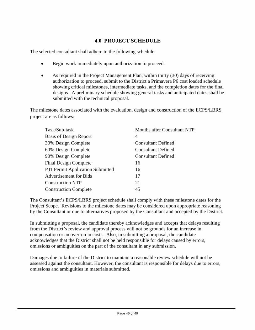
Page 46 of 49
4.0 PROJECT SCHEDULE
The selected consultant shall adhere to the following schedule:
• Begin work immediately upon authorization to proceed. • As required in the Project Management Plan, within thirty (30) days of receiving
authorization to proceed, submit to the District a Primavera P6 cost loaded schedule showing critical milestones, intermediate tasks, and the completion dates for the final designs. A preliminary schedule showing general tasks and anticipated dates shall be submitted with the technical proposal.
The milestone dates associated with the evaluation, design and construction of the ECPS/LBRS project are as follows:
Task/Sub-task Months after Consultant NTP Basis of Design Report 4 30% Design Complete Consultant Defined 60% Design Complete Consultant Defined 90% Design Complete Consultant Defined Final Design Complete 16 PTI Permit Application Submitted 16 Advertisement for Bids 17 Construction NTP 21 Construction Complete 45
The Consultant’s ECPS/LBRS project schedule shall comply with these milestone dates for the Project Scope. Revisions to the milestone dates may be considered upon appropriate reasoning by the Consultant or due to alternatives proposed by the Consultant and accepted by the District. In submitting a proposal, the candidate thereby acknowledges and accepts that delays resulting from the District’s review and approval process will not be grounds for an increase in compensation or an overrun in costs. Also, in submitting a proposal, the candidate acknowledges that the District shall not be held responsible for delays caused by errors, omissions or ambiguities on the part of the consultant in any submission.
Damages due to failure of the District to maintain a reasonable review schedule will not be assessed against the consultant. However, the consultant is responsible for delays due to errors, omissions and ambiguities in materials submitted.

Page 47 of 49
5.0 EVALUATION AND SELECTION PROCESS Once all Qualifications and Technical proposals have been received, the following steps will be followed to select the Consultant: 1. The written Qualifications and Technical Proposals will be evaluated and scored by a District
Selection Committee utilizing the following criteria:
Written Qualifications (30% of Total Score) • Project Team – 5 points • Proposed Project Manager – 10 points • Experience and previous performance of proposed team and staff on similar projects
– 5 points • Clarity and organization of proposal – 5 points • Local participation and MBE/WBE participation – 5 points
Written Technical Approach (35% of Total Score) • Project understanding – 10 points • Proposed methods to accomplish scope of work, alternative approaches, and risk
management – 25 points
2. Upon completion of the scoring and ranking of the written submittals, the District may select the top ranked firm to negotiate with or may short list firms to deliver a presentation and provide further clarification of their approach. The District may prepare and submit a list of questions to each of the short-listed firms to address during their interview.
The District may allot up to 90-minutes for the presentation and interview, including a 30-minute question and answer period. Key project personnel will be expected to take the lead in presenting and answering questions regarding the technical proposal. Upon completion of the presentations, the District selection committee will score each firm according to the following criteria:
Presentation and Interview (35% of Total Score) • Quality and clarity of presentation – 5 points • Project Manager’s ability to communicate project understanding – 15 points • Team Support on Project Understanding – 5 points • Adequacy of Response to District Questions – 10 points
3. For evaluations taken to the presentation stage, the scores for the Presentation and Interview
will be combined with the scores from the evaluation of the written submittals to determine the overall ranking of the short-listed firms.
4. After evaluation, the District will enter into negotiations with the highest ranked firm to develop a final and mutually agreed-upon scope and price. The District will require that the fee (profit) include a base fee of 10% and a fee at risk of 5% based on successfully meeting

Page 48 of 49
key performance indicators (KPIs). These KPIs would be mutually agreed upon as part of the negotiations and may include, but not be limited to, meeting schedule requirements, designing to budget, preparing final engineer’s estimates within 10% of the bid award amount, achieving acceptable response times, etc. If agreement cannot be reached with the highest ranked firm, the District may initiate negotiations with the next highest ranked firm.
5. Upon reaching agreement on the scope and total not-to-exceed price for the project, the Selection Committee will make a recommendation to award to the District’s Consultant Review Committee (CRC) for review.
6. Upon approval by CRC, District Staff will report to the Board of Trustees and make a recommendation to enter into a contract based on the outcome of the negotiations.
7. The selected consultant cannot commence work on any aspects of the project prior to the Board approval and subsequent execution of the District’s standard contract.

Page 49 of 49
6.0 SUBMISSION OF PROPOSALS
One original and seven (7) copies of the technical proposals are to be delivered to the following names and address:
Julius Ciaccia, Executive Director Northeast Ohio Regional Sewer District 3900 Euclid Avenue Cleveland, Ohio 44115-2504 Attn.: Kellie Rotunno, Director of Engineering & Construction
Deadline for submission of proposals is indicated on Page 1 of this RFP.
Late submittals will not be considered.
All questions regarding this RFP shall be directed to Mr. Steve Janosko.
END OF RFP
ATTACHMENTS TO FOLLOW