reproductions supplied by edrs are the best that can be made … · 2014-06-04 · high-speed...
TRANSCRIPT
DOCUMENT RESUME
ED 458 132 SE 065 303
TITLE Patterns, Functions, and Algebra: Wired for Space. NASAConnect: Program 3 in the 2000-2001 Series.
INSTITUTION National Aeronautics and Space Administration, Hampton, VA.Langley Research Center.
REPORT NO EG-2000-10-17-LaRCPUB DATE 2000-00-00NOTE 28p.; Accompanying videotape not available from ERIC. For
other documents in series, see SE 065 301-305.PUB TYPE Guides Classroom Teacher (052)EDRS PRICE MF01/PCO2 Plus Postage.DESCRIPTORS *Algebra; *Electricity; *Functions (Mathematics); Integrated
Activities; Intermediate Grades; Junior High Schools;*Magnets; Mathematics Education; *Patterns in Mathematics;Science and Society; Science Instruction; Space Sciences;Technology Education
IDENTIFIERS *Spacecraft
ABSTRACTThis teaching unit is designed to help students in grades 5
to 8 explore the concepts of patterns, functions, and algebra in the contextof propelling spacecraft. The units in the series have been developed toenhance and enrich mathematics, science, and technology education and toaccommodate different teaching and learning styles. Each unit consists ofbackground notes for the teacher, a list of teacher resources, and twoactivities, one of which is Web-based, complete with blackline masters. Alsoincluded are suggestions for extensions to the problems and theirrelationships to national mathematics, science, and technology standards. Inthis activity, students learn how patterns, functions, and algebra can helpNational Aeronautics and Space Administration (NASA) engineers design newways of propelling spacecraft and how electricity and magnetism are beingused to replace the fuel-consuming rocket propulsion commonly used to delivera push to spacecraft. (MM)
Reproductions supplied by EDRS are the best that can be madefrom the original document.
A A
Patterns, Functions,and Algebra:
U S DEPARTMENT OF EDUCATIONOffice of Educational Research and Improvement
EDUCATIONAL RESOURCES INFORMATION
1..CENTER (ERIC)
.lits document has been reproduced asreceived from the person or organizationoriginating it
0 Minor changes have been made toimprove reproduction quality
Points of view or opinions stated in thisdocument do not necessarily representofficial OERI position or policy
Wired for Space
Educator's Guide
Teachers &Students
ProVaat Iheerview 01
Classroom Activity
Student Cue Cards p. 2,3
Web Activity p.24
esourteS P-25
Publication Number EG-2000-10-17-LaRC This publication is in the PublDomain and is not protected by copyright. Permission is not required for duplication .
prc-r rnpy ARI P
Program 3 in the 2000-2001 NASA CONNECT Series
Patterns, Functions, and Algebra: Wired for Space
PROGRAM OVERVIEW
SUMMARY AND OBJECTIVES
In Patterns, Functions, and Algebra: Wired for Space, students will learn how
patterns, functions, and algebra can help NASA engineers design new ways of
propelling spacecraft and how electricity and magnetism are being used to replace
the fuel-consuming rocket propulsion commonly used to deliver a push to
spacecraft. Students will discover three projects that use electromagnetism in a
dynamic way: the Magnetic Levitation Launch System (Maglev), the Propulsive
Small Expendable Deployer System (ProSEDS), and the student-designed Icarus
satellite. Students will observe NASA engineers using algebra to design and test
the Icarus satellite. Through classroom and on-line activities, students will make
connections between electricity and magnetism and between NASA research and
the mathematics, science, and technology they learn in their classroom.
INTERACTIVE ACTIVITIES
Questions are posed throughout the video by Norbert, the animated cohost of
NASA CONNECT. These questions direct the instruction and encourage students to
think about the concepts being presented. An icon appears in the video to suggest
to teachers an appropriate 'place to pause the video and discuss the answers to the
questions. Students record their answers on the Student Cue Cards (p. 23).
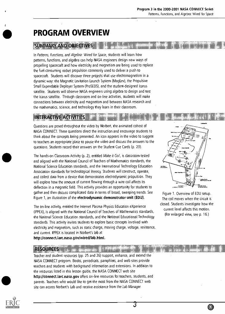
The hands-on Classroom Activity (p. 2), entitled Make it Go!, is classroom-tested
and aligned with the National Council of Teachers of Mathematics standards, the
National Science Education standards, and the International Technology Education
Association standards for technological literacy. Students will construct, operate,
and collect data from a device that demonstrates electrodynamic propulsion. They
will explore how the amount of current flowing through a wire coil affects its
deflection in a magnetic field. This activity provides an opportunity for students to
gather and then discuss complicated data in terms of broad, sweeping trends. See
Figure 1, an illustration of the electrodynamic demonstrator unit (EDU).
The on-line activity, entitled the Internet Plasma Physics Education eXperience
(IPPEX), is aligned with the National Council of Teachers of Mathematics standards,
the National Science Education standards, and the National Educational Technology
standards. This activity invites students to explore basic concepts involved with
electricity and magnetism, such as static charge, moving charge, voltage, resistance,
and current. IPPEX is located in Norbert's lab at
http://connect.larc.nasa.gov/wired/lab.html.
z RESOURCES
Teacher and student resources (pp. 25 and 26) support, enhance, and extend the
NASA CONNECT program. Books, periodicals, pamphlets, and web sites provide
teachers and students with background information and extensions. In addition to
the resources listed in this lesson guide, the NASA CONNECT web site
http://connectiarc.nasa.gov offers on-line resources for teachers, students, and
parents. Teachers who would like to get the most from the NASA CONNECT web
site can access Norbert's Lab and receive assistance from the Lab Manager.
Figure 1. Overview of EDU setup.
The coil moves when the circuit is
closed. Students investigate how the
current level affects this motion.
(For enlarged view, see p. 16.)
Program 3 in the 2000-2001 NASA CONNECT Series
Patterns, Functions, and Algebra: Wired for Space
THE CLASSROOM ACTIVITY
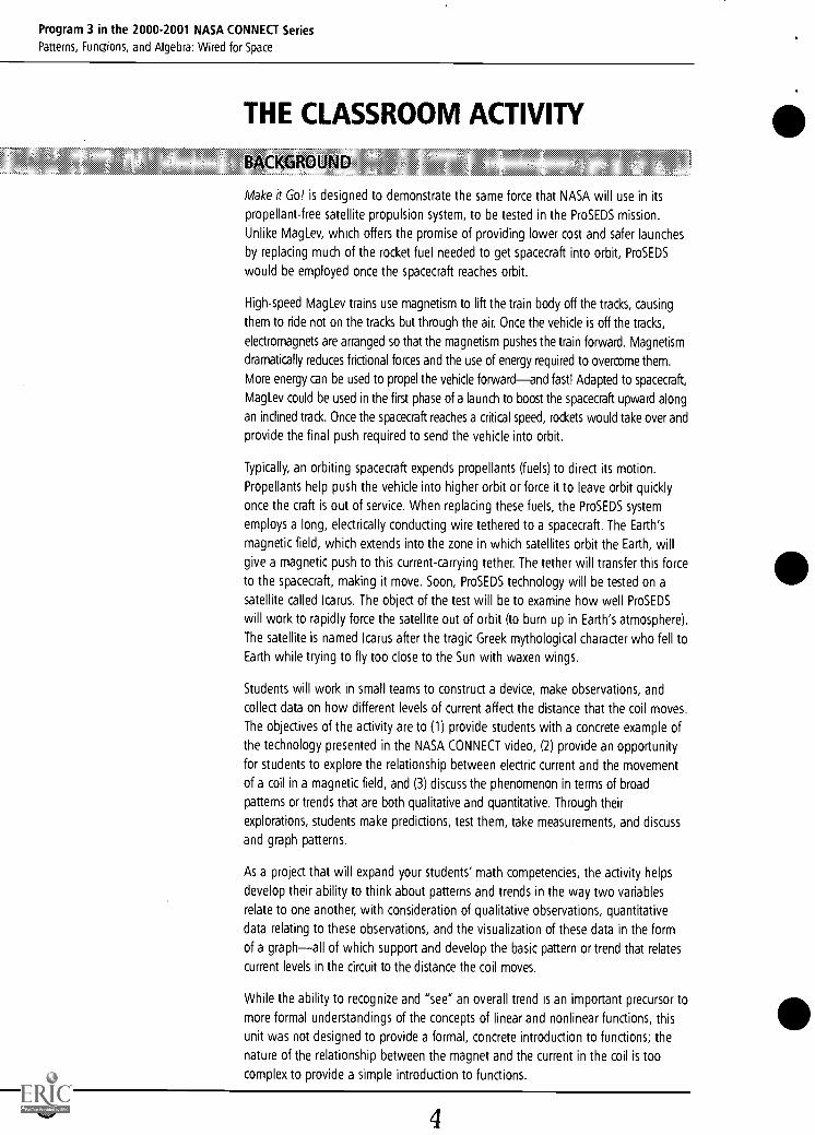
BAcKGROUND
Make it Go! is designed to demonstrate the same force that NASA will use in its
propellant-free satellite propulsion system, to be tested in the ProSEDS mission.
Unlike MagLev, which offers the promise of providing lower cost and safer launches
by replacing much of the rocket fuel needed to get spacecraft into orbit, ProSEDS
would be employed once the spacecraft reaches orbit.
High-speed Maglev trains use magnetism to lift the train body off the tracks, causing
them to ride not on the tracks but through the air. Once the vehicle is off the tracks,
electromagnets are arranged so that the magnetism pushes the train forward. Magnetism
dramatically reduces frictional forces and the use of energy required to overcome them.
More energy can be used to propel the vehicle forwardand fast! Adapted to spacecraft,
MagLev could be used in the first phase of a launch to boost the spacecraft upward along
an inclined track. Once the spacecraft reaches a critical speed, rockets would take over and
provide the final push required to send the vehicle into orbit.
Typically, an orbiting spacecraft expends propellants (fuels) to direct its motion.
Propellants help push the vehicle into higher orbit or force it to leave orbit quickly
once the craft is out of service. When replacing these fuels, the ProSEDS system
employs a long, electrically conducting wire tethered to a spacecraft. The Earth's
magnetic field, which extends into the zone in which satellites orbit the Earth, will
give a magnetic push to this current-carrying tether. The tether will transfer this force
to the spacecraft, making it move. Soon, ProSEDS technology will be tested on a
satellite called Icarus. The object of the test will be to examine how well ProSEDS
will work to rapidly force the satellite out of orbit (to burn up in Earth's atmosphere).
The satellite is named Icarus after the tragic Greek mythological character who fell to
Earth while trying to fly too close to the Sun with waxen wings.
Students will work in small teams to construct a device, make observations, and
collect data on how different levels of current affect the distance that the coil moves.
The objectives of the activity are to (1) provide students with a concrete example of
the technology presented in the NASA CONNECT video, (2) provide an opportunity
for students to explore the relationship between electric current and the movement
of a coil in a magnetic field, and (3) discuss the phenomenon in terms of broad
patterns or trends that are both qualitative and quantitative. Through their
explorations, students make predictions, test them, take measurements, and discuss
and graph patterns.
As a project that will expand your students' math competencies, the activity helps
develop their ability to think about patterns and trends in the way two variables
relate to one another, with consideration of qualitative observations, quantitative
data relating to these observations, and the visualization of these data in the form
of a graphall of which support and develop the basic pattern or trend that relates
current levels in the circuit to the distance the coil moves.
While the ability to recognize and "see" an overall trend is an important precursor to
more formal understandings of the concepts of linear and nonlinear functions, this
unit was not designed to provide a formal, concrete introduction to functions; the
nature of the relationship between the magnet and the current in the coil is too
complex to provide a simple introduction to functions.
Program 3 in the 2000-2001 NASA CONNECT Series
Patterns, Functions, and Algebra: Wired for Space
NATIONAL STANDARDS
MATHEMATICS STANDARDS
Understand patterns, relations, and functions.
Use mathematical models to represent and understand quantitative relationships.
Analyze change in various contexts.
Understand measurable attributes of objects and the units, systems, and
processes of measurement.
Apply appropriate techniques, tools, and formulas to determine measurement.
Formulate questions that can be addressed with data and collect, organize, and
display relevant data to answer them.
Develop and evaluate inferences and predictions that are based on data.
Recognize and apply mathematics in contexts outside mathematics.
Use representations to model and interpret physical, social, and mathematical
phenomena.
SCIENCE STANDARDS
Abilities necessary to do scientific inquiry
Understandings about scientific inquiry
Motions and forces
Transfer of energy
TECHNOLOGY STANDARDS
Various relationships exist between technology and other fields of study.
Throughout history, innovations in technology have resulted from the demands,
values, and interests of individuals, businesses, industry, and societies.
The process of experimentation, which is common in science, can also be used to
solve technological problems.
Some technological problems are best solved through experimentation.
Follow step-by-step directions to assemble a product.
5
Program 3 in the 2000-2001 NASA CONNECT Series
Patterns, Functions, and Algebra: Wired for Space
INSTRUCTIONAL OBJECTIVES
Students will be able to
construct an electrodynamic demonstrator unit (EDU).
use the EDU to observe that changing the current in a circuit affects the light
emitted from an LED (light emitting diode).
observe and understand that a wire with electricity flowing through it can be
made to move in the presence of a magnet.
observe that changing the current in a circuit affects the amount of movement
induced in the electric wire when a magnetic field is present.
measure, record, and graph the relationship between the electric current and the
wire movement.
discuss general trends in the data.
VOCABULARY
Here are some terms that are used throughout this activity with which your students
may not be familiar. You may want to spend some time developing their
understandings'of the relevant concepts.
current the flow of electrons or charged particles in an electric circuit
force a push or a pull on an object
electrodynamic related to the interactions of electric currents with magnetic fields
electromagnetic related to electricity and magnetism
trend a general pattern of how a system behaves, relating two or more variables
to one another
6
Program 3 in the 2000-2001 NASA CONNECT Series
Patterns, Functions, and Algebra: Wired for Space
PREI)ARING FOR TiIE ACTIVITY
MATERIALS
For items that may be difficult to find, Radio Shack part numbers and pricing
information are included.*NASA does not endorse Radio Shack as a supplier
of materials; these materials can be replaced with parts from other suppliers, as well.
FOR ENTIRE CLASS
wire cuttersscissors
PER STUDENT TEAM (2-3 STUDENTS)
1 tall, sturdy box (at least 30 cm high, 15 cm wide, and 30 cm deep), with magnet
hole prepared (See instructions for preparing the magnet hole in the Advance
Preparation section of this guide, p.6.)
1 piece of corrugated cardboard about 15 cm x 30 cm (approximately the size of
the box top) to serve as a platform for the batteries, LED, and Current Controller.
Electrical resistors in the following sizes:
Required for Basic activity Used in Extension activity
22 ohm 33 ohm
82 ohm 47 ohm
220 ohm 68 ohm
470 ohm 100 ohm
1000 (1K) ohm 150 ohm
330 ohm
All these resistors may be obtained from Radio Shack in packets of 5 for 49/.
1 roll of magnet wire (30 or 32 AWG), with enamel coating
(Radio Shack offers a magnet wire 3-pack: 40 ft of 22 gauge, 75 ft of 26 gauge,
and 200 ft of 30 gauge wire. Part number 278-1345; $3.99)
alligator clip leads (small toothed)
(Radio Shack sells 14 in. length, double-headed alligator clip leads. Part number
278-1156; package of 10, $3.99)
24 in. length, double-headed alligator clip leads(Radio Shack: Part number 278-1157; package of 8, $3.99)
2 fresh D cell batteriesbattery holder for two D-cells (for D-cells with wires/leads attached)
(Radio Shack: Part number 270-386; $1.59)
1 LED (light emitting diode)
(Radio Shack provides an LED assortment: Part number.276-1622; package of 20, $2.29)
tape (cellophane or masking)
fine sandpaper for removing enamel insulation from magnet wire
1 Current Controller, prepared by teacher ahead of time (See instructions on
Current Controller Templates, Figure 5, p. 20.)
strip of manila folder, 3 cm x 16 cm (prepared ahead of time by teacher)
toothpickmm rulerfilm can (container for 35-mm film; available free to teachers at most film
developing establishments)
cow magnet (available through science education supply catalogues)
*The use of trademarks or names of manufacturers in this report is for accurate reporting and does not
constitute an official endorsement, either expressed or implied, of such products or manufacturers by the
National Aeronautics and Space Administration.
7
Program 3 in the 2000-2001 NASA CONNECT Series
Patterns, Functions, and Algebra: Wired for Space
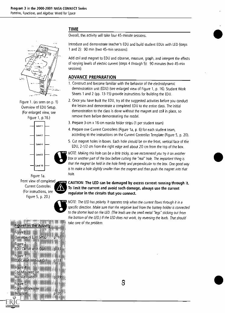
Figure 1. (as seen on p. 1)
Overview of EDU Setup.
(For enlarged view, see
Figure 1, p.16.)
Level 1
Level 2
Level 4
Level 8
Level 16
Figure la.
Front view of completed
Current Controller.
(For instructions, see
Figure 5, p. 20.)
Figures in the Activity
CAUTION
Figurel
Overview of EDU Setup .. p. 16
Figure 2.
EDU Circuit with Cod . p. 17
Figure 1
EDU Circuit Without Coil . p. 18
Figure 4,
Coil Mounted on
Manilla Fokier p 19
Figure 5
Current Controller
Templates p 20
TIME
Overall, this activity will take four 45-minute sessions.
Introduce and demonstrate teacher's EDU and build student EDUs with LED (steps
1 and 2): 90 min (two 45-min sessions).
Add coil and magnet to EDU and observe, measure, graph, and interpret the effects
of varying levels of electric current (steps 4 through 5): 90 minutes (two 45-min
sessions).
ADVANCE PREPARATION
1. Construct and become familiar with the behavior of the electrodynamic
demonstration unit (EDU) (see enlarged view of Figure 1, p. 16). Student Work
Sheets 1 and 2 (pp. 13-15) provide instructions for building the EDU.
2. Once you have built the EDU, try all the suggested activities before you conduct
the lesson and demonstrate a completed EDU to the entire class. The initial
demonstration to the class is done without the magnet and coil in place, so
remove them before demonstrating the model.
3. Prepare 3-cm x 16-cm manila folder strips (1 per student team)
4. Prepare one Current Controllers (Figure la, p. 6) for each student team,
according to the instructions on the Current Controller Template (Figure 5, p. 20).
5. Cut magnet holes in boxes. Each hole should be on the front, vertical face of lie
EDU, 2-1/2 cm from the right edge and about 20 cm from the top of the box.
NOTE: Making this hole can be a little tricky, so we recommend you try it on another
box or another part of the box before cutting the "real" hole. The important thing is
that the magnet be held in the hole firmly and perpendicular to the box. One good way
is to make a hole slightly smaller than the magnet and then push the magnet into that
hole.
CAUTION: The LED can be damaged by excess current running through it.To limit the current and avoid such damage, always use the currentregulator in the circuits that you connect
NOTE: The LED has polarity It operates only when the current flows through it in a
specific direction. Make sure that the negative lead from the battery holder is connected
to the shorter lead on the LED. (The leads are the small metal "legs" sticking out from
the bottom of the LED.) If the LED does not work, try reversing the leads. That_should
take care of the problem.
8
0
Program 3 in the 2000-2001 NASA CONNECt Series
Patterns, Functions, and Algebra: Wired for Space
THE ACTIVITY
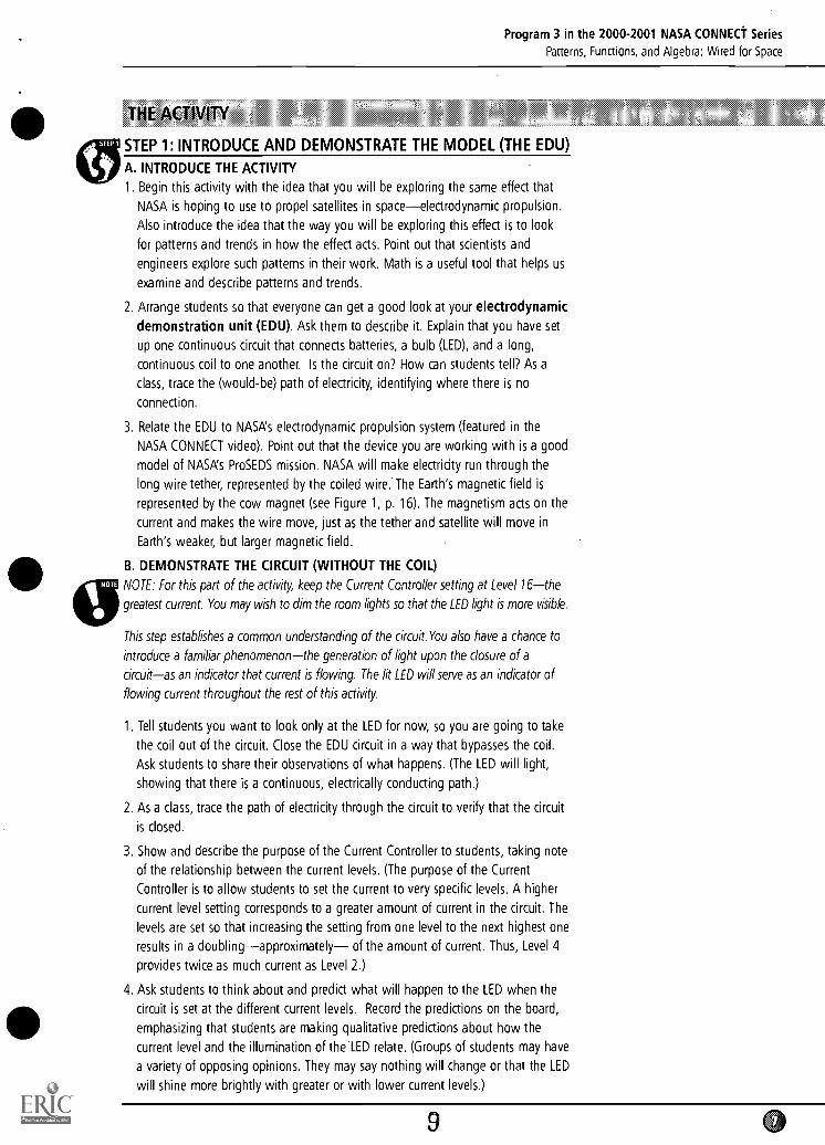
STEP 1: INTRODUCE AND DEMONSTRATE THE MODEL (THE EDU)
A. INTRODUCE THE ACTIVITY
1. Begin this activity with the idea that you will be exploring the same effect that
NASA is hoping to use to propel satellites in spaceelectrodynamic propulsion.
Also introduce the idea that the way you will be exploring this effect is to look
for patterns and trends in how the effect acts. Point out that scientists and
engineers explore such patterns in their work. Math is a useful tool that helps us
examine and describe patterns and trends.
2. Arrange students so that everyone can get a good look at your electrodynamic
demonstration unit (EDU). Ask them to describe it. Explain that you have set
up one continuous circuit that connects batteries, a bulb (LED), and a long,
continuous coil to one another. Is the circuit on? How can students tell? As a
class, trace the (would-be) path of electricity, identifying where there is no
connection.
3. Relate the EDU to NASAs electrodynamic propulsion system (featured in the
NASA CONNECT video). Point out that the device you are working with is a good
model of NASA's ProSEDS mission. NASA will make electricity run through the
long wire tether, represented by the coiled wire:The Earth's magnetic field is
represented by the cow magnet (see Figure 1, p. 16). The magnetism acts on the
current and makes the wire move, just as the tether and satellite will move in
Earth's weaker, but larger magnetic field.
B. DEMONSTRATE THE CIRCUIT (WITHOUT THE COIL)
NOTE: For this part of the activity, keep the Current Controller setting at Level 16the
greatest current. You may wish to dim the room lights so that the LED light is more visible.
This step establishes a common understanding of the circuit. You also have a chance to
introduce a familiar phenomenonthe generation of light upon the closure of a
circuitas an indicator that current is flowing. The lit LED will serve as an indicator of
flowing current throughout the rest of this activity.
1. Tell students you want to look only at the LED for now, so you are going to take
the coil out of the circuit. Close the EDU circuit in a way that bypasses the coil.
Ask students to share their observations of what happens. (The LED will light,
showing that there is a continuous, electrically conducting path.)
2. As a class, trace the path of electricity through the circuit to verify that the circuit
is closed.
3. Show and describe the purpose of the Current Controller to students, taking note
of the relationship between the current levels. (The purpose of the Current
Controller is to allow students to set the current to very specific levels. A higher
current level setting corresponds to a greater amount of current in the circuit. The
levels are set so that increasing the setting from one level to the next highest one
results in a doublingapproximately of the amount of current. Thus, Level 4
provides twice as much current as Level 2.)
4. Ask students to think about and predict what will happen to the LED when the
circuit is set at the different current levels. Record the predictions on the board,
emphasizing that students are making qualitative predictions about how the
current level and the illumination of the.LED relate. (Groups of students may have
a variety of opposing opinions. They may say nothing will change or that the LED
will shine more brightly with greater or with lower current levels.)
9
Program 3 in the 2000-2001 NASA CONNECT Series
Patterns, Functions, and Algebra: Wired for Space
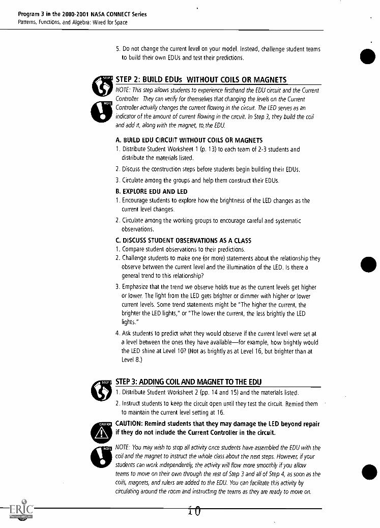
5. Do not change the current level on your model. Instead, challenge student teams
to build their own EDUs and test their predictions.
STEP 2: BUILD EDUs WITHOUT COILS OR MAGNETS
NOTE: This step allows students to experience firsthand the EDU circuit and the Current
Controller They can verify for themselves that changing the levels on the Current
Controller actually changes the current flowing in the circuit. The LED serves as an
indicator of the amount of current flowing in the circuit. In Step 3, they build the coil
and add it, along with the magnet, to,the EDU.
A. BUILD EDU CIRCUIT WITHOUT COILS OR MAGNETS
1. Distribute Student Worksheet 1 (p. 13) to each team of 2-3 students and
distribute the materials listed.
2. Discuss the construction steps before students begin building their EDUs.
3. Circulate among the groups and help them construct their EDUs.
B. EXPLORE EDU AND LED
1. Encourage students to explore how the brightness of the LED changes as the
current level changes.
2. Circulate among the working groups to encourage careful and systematic
observations.
C. DISCUSS STUDENT OBSERVATIONS AS A CLASS
1. Compare student observations to their predictions.
2. Challenge students to make one (or more) statements about the relationship they
observe between the current level and the illumination of the LED. Is there a
general trend to this relationship?
3. Emphasize that the trend we observe holds true as the current levels get higher
or lower. The light from the LED gets brighter or dimmer with higher or lower
current levels. Some trend statements might be "The higher the current, the
brighter the LED lights," or "The lower the current, the less brightly the LED
lights."
4. Ask students to predict what they would observe if the current level were set at
a level between the ones they have availablefor example, how brightly would
the LED shine at Level 10? (Not as brightly as at Level 16, but brighter than at
Level 8.)
STEP 3: ADDING COIL AND MAGNET TO THE EDU
1. Distribute Student Worksheet 2 (pp. 14 and 15) and the materials listed.
2. Instruct students to keep the circuit open until they test the circuit. Remind them
to maintain the current level setting at 16.
CAUTION: Remind students that they may damage the LED beyond repairif they do not include the Current Controller in the circuit.
NOTE: You may wish to stop all activity once students have assembled the EDU with the
coil and the magnet to instruct the whole class about the next steps. However, if your
students can work independently, the activity will flow more smoothly if you allow
teams to move on their own through the rest of Step 3 and all of Step 4, as soon as the
coils, magnets, and rulers are added to the EDU. You can facilitate this activity by
circulating around the room and instructing the teams as they are ready to move on.
Program 3 in the 2000-2001 NASA CONNECT Series
Patterns, Functions, and Algebra: Wired for Space
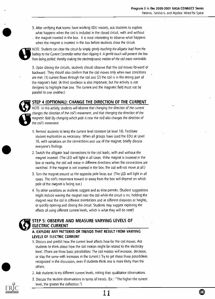
3. After verifying that teams have working EDU models, ask students to explore
what happens when the coil is included in the closed circuit, with and without
the magnet inserted in the box. It is most interesting to observe what happens
when the magnet is inserted in the box before students close the circuit.
NOTE: Students can close the circuit by simp4r, gently touching the affigator lead from the
battery to the Current Controller rather than clipping it. A gentle touch will prevent the box
from being jostled, thereby making the electrodynamic motion of the coil more noticeable.
3. Upon closing the circuits, students should observe that the coil moves forward or
backward. They should also confirm that the coil moves only when two conditions
are met: (1) current flows through the coil and (2) the coil is in the strong part of
the magnet's field. (A third condition is also important, but the activity is not
designed to highlight that one. The current and the magnetic field must not be
parallel to one another.)
STEP 4 (OPTIONAL): CHANGE THE DIRECTION OF THE CURRENT
NOTE: In this activity, students will observe that changing the direction of the current
changes the direction of the coil's movement, and that changing the direction of the
magnetic field (by changing which po/e is near the coil) also changes the direction of
the coil's movement.
1. Remind students to keep the current level constant (at level 16). Facilitate
student exploration as necessary: When all groups have used the EDU at Level
16, with variations on the connections and use of the magnet, briefly discuss
everyone's findings.
2. Switch the alligator lead connections to the coil leads, with and without the
magnet inserted. (The LED will light in all cases. If the magnet is inserted in the
box or nearby, the coil will move in different directions when the connections are
switched. If the magnet is not inserted in the box, the coil will not move at all.)
3. Turn the magnet around so the opposite pole faces out. (The LED will light in all
cases. The coil's movement toward or away from the box will depend on which
pole of the magnet is facing out.)
4. Try other variations as students suggest and as time permits. (Student suggestions
might include waving the magnet near the coil while the circuit is on, holding the
magnet near the coil in different orientations and at different distances or heights,
or quickly opening and closing the circuit. Students may suggest exploring the
effects of using different current levels, which is what they will do next!)
STEP 5: OBSERVE AND MEASURE VARYING LEVELS OFELECTRIC CURRENT
A. EXPLORE ANY PATTERNS OR TRENDS THAT RESULT FROM VARYING
LEVELS OF ELECTRIC CURRENT
1. Discuss and predict how the current level affects how far the coil moves. Ask
students to think about how the coil motion might be related to the electricity
level. (There are three basic possibilities: The coil motion will increase, decrease,
or stay the same with increases in the current.) Try to get these three possibilities
recognized in the discussion, even if students think one is more likely than the
others.
2. Ask students to try different current levels, noting their qualitative observations.
3. Discuss the student observations in terms of trends. (Ex.: "The higher the current
level, the greater the deflection.")
11 0
Program 3 in the 2000-2001 NASA CONNECT Series
Patterns, Functions, and Algebra: Wired for Space
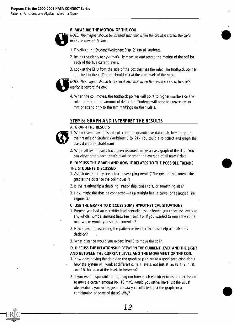
B. MEASURE THE MOTION OF THE COIL
NOTE: The magnet should be inserted such that when the circuit is closed, the coil's
motion is toward the box.
1. Distribute the Student Worksheet 3 (p. 21) to all students.
2. Instruct students to systematically measure and record the motion of the coil for
each of the five current levels.
3. Look at the EDU from the side of the box that has the ruler. The toothpick pointer
attached to the coil's card should rest at the zero mark of the ruler.
NOTE: The magnet should be inserted such that when the circuit is closed, the coil's
motion is toward the box.
4. When the coil moves, the toothpick pointer will point to higher numbers on the
ruler to indicate the amount of deflection. Students will need to convert cm to
mm or attend only to the mm markings on their rulers.
STEP 6: GRAPH AND INTERPRET THE RESULTS
A. GRAPH THE RESULTS
1. When teams have finished collecting the quantitative data, ask them to graph
their results on Student Worksheet 3 (p. 21). You could also collect and graph the
class data on a chalkboard.
2. When all team results have been recorded, make a class graph of the data. You
can either graph each team's result or graph the average of all teams' data.
B. DISCUSS THE GRAPH AND HOW IT RELATES TO THE POSSIBLE TRENDS
THE STUDENTS DISCUSSED
1. Ask students if they see a broad, sweeping trend. ("The greater the current, the
greater the distance the coil moves.")
2. Is the relationship a doubling relationship, close to it, or something else?
3. How might the dots be connectedas a straight line, a curve, or as jagged line
segments?
C. USE THE GRAPH TO DISCUSS SOME HYPOTHETICAL SITUATIONS
1. Pretend you had an electricity level controller that allowed you to set the levels at
any whole number amount between 1 and 16. If you wanted to move the coil 7
mm, where would you set the controller?
2. How does understanding the pattern or trend of the data help us make this
decision?
3. What distance would you expect level 3 to move the coil?
D. DISCUSS THE RELATIONSHIP BETWEEN THE CURRENT LEVEL AND THE LIGHT
AND BETWEEN THE CURRENT LEVEL AND THE MOVEMENT OF THE COIL
1. How does having the data and the graph help us make a good prediction about
how the system will work at different current levels, not just at Levels 1, 2, 4, 8,
and 16, but also at the levels in between?
2. If you were responsible for figuring out how much electricity to use to get the coil
to move a certain amount (ex. 10 mm), would you rather have just the visual
observations you made, just the data you collected, just the graph, or a,
combination of some of these? Why?
12
Program 3 in the 2000-2001 NASA CONNECT Series
Patterns, Functions, and Algebra: Wired for Space
3. What do the visual observations, the data we collected, and the graph all tell us
about how the current level relates to the light emitted or the distance the coil
moves? How do they tell us the same thing, but differently?
NOTE: If you have more time to give to this activity, you could more completely address
data analysis as part of this lesson. After allowing student teams to work independently
to collect the data, the class can share all its coil motion data. Then ask them to
determine what values are typical for each current level. They might consider averaging
data, but other options also existthe most common value (mode), or even the middle
value (median) might be more "typical" than the average. Looking at the data critically
may provide an opportunity to consider when it seems appropriate to re-run trials when
faulty data is suspected.
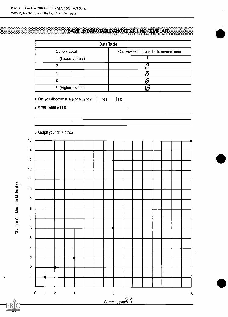
NOTE: The Sample Data Table and Graphing Template (p. 22) was collected by one
team of students during the pilot test of this activity in Cambridge, MA. Note how
nearly linear this graph is. Isn't it tempting to draw a straight line connecting the dots?
But do we really know enough to do that?
We want to instill in students respect for the data and a cautious attitude in interpreting
it, so before we "connect the dots," wait a moment. Think about this: When we
connect the data points on this graph with straight line segments, we are thereby
implying something about all the values along the line, i.e., about the intervening values
where we did not collect data. We will be expressing an assumption about the
movement of the coil at current levels where we did not test. Are these assumptions
valid?
Moreover, how sure are we about our data points? It's pretty hard to measure the
movement of that coil in millimeters! Do we want to base our curve on one set of data
points? What is the best curve to represent the actual relationship? A smooth curve? A
jagged set of line segments? Any sweep of your pen connecting these data will, in fact,
show an approximation of the function that you believe exLsts.
We don't know enough about the subtleties of this system to give you an answer That
is precisely the value of gathering a lot of data in scientific explorations. Check out
Extension 3 (p.11) to pursue this discussion a little further.
EXTENSIONS
1. To further develop this sense of trends, examine other relationships and compare
them to the graphs and data you made for this unit. Simple relationships are the
more M&Ms in a bag, the more it weighs; the more students in the room, the
more shoes there are.
2. To further develop the idea that the relationship between the movement of the
coil and the current is a reliable one and that every specific input has a specific
output (that's a function), ask students to try to guess at which electricity level
their partners are setting the circuit, based on how far the coil is moving.
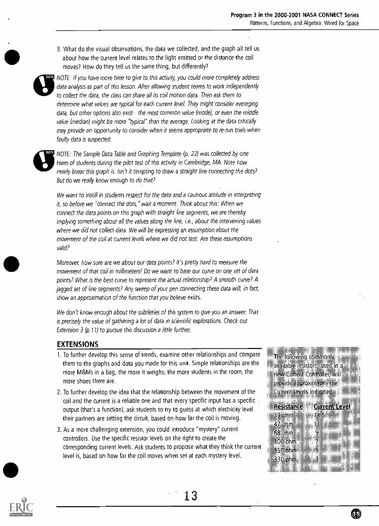
3. As a more challenging extension, you could introduce "mystery" current
controllers. Use the specific resistor levels on the right to create the
corresponding current levels. Ask students to propose what they think the current
level is, based on how far the coil moves when set at each mystery level.
13
The following commonly
available resistors, used in a
new Current Controller, will
provide approximately the
Current Levels indicated.
Begjsunce33 ohm
47 ohm
68 ohm
100 ohm
150 ohm
330 ohm
Current Levet13
11
9
7
5
3
5
0
Program 3 in the 2000-2001 NASA CONNECT Series
Patterns, Functions, and Algebra: Wired for Space
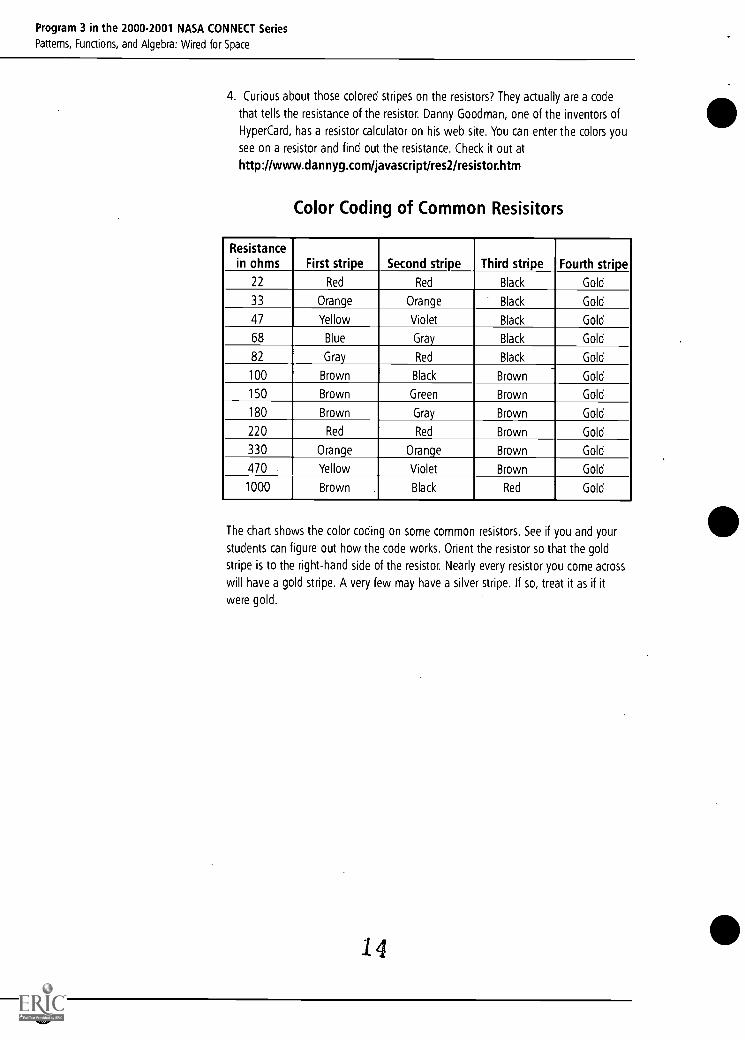
4. Curious about those colored stripes on the resistors? They actually are a code
that tells the resistance of the resistor. Danny Goodman, one of the inventors of
HyperCard, has a resistor calculator on his web site. You can enter the colors you
see on a resistor and find out the resistance. Check it out at
http://www.dannyg.com/javascript/res2/resistor.htm
Color Coding of Common Resisitors
Resistancein ohms First stripe Second stripe Third stripe Fourth stripe
22 Red Red Black Gold
33 Orange Orange Black Gold
47 Yellow Violet Black Gold
68 Blue Gray Black Gold
82 Gray Red Black Gold
100 Brown Black Brown Gold
150 Brown Green Brown Gold
180 Brown Gray Brown Gold
220 Red Red Brown Gold
330 Orange Orange Brown Gold
470 . Yellow Violet Brown Gold
1000 Brown Black Red Gold
The chart shows the color coding on some common resistors. See if you and your
students can figure out how the code works. Orient the resistor so that the gold
stripe is to the right-hand side of the resistor. Nearly every resistor you come across
will have a gold stripe. A very few may have a silver stripe. If so, treat it as if it
were gold.
14
Program 3 in the 2000-2001 NASA CONNECT Series
Patterns, Functions, and Algebra: Wired for Space
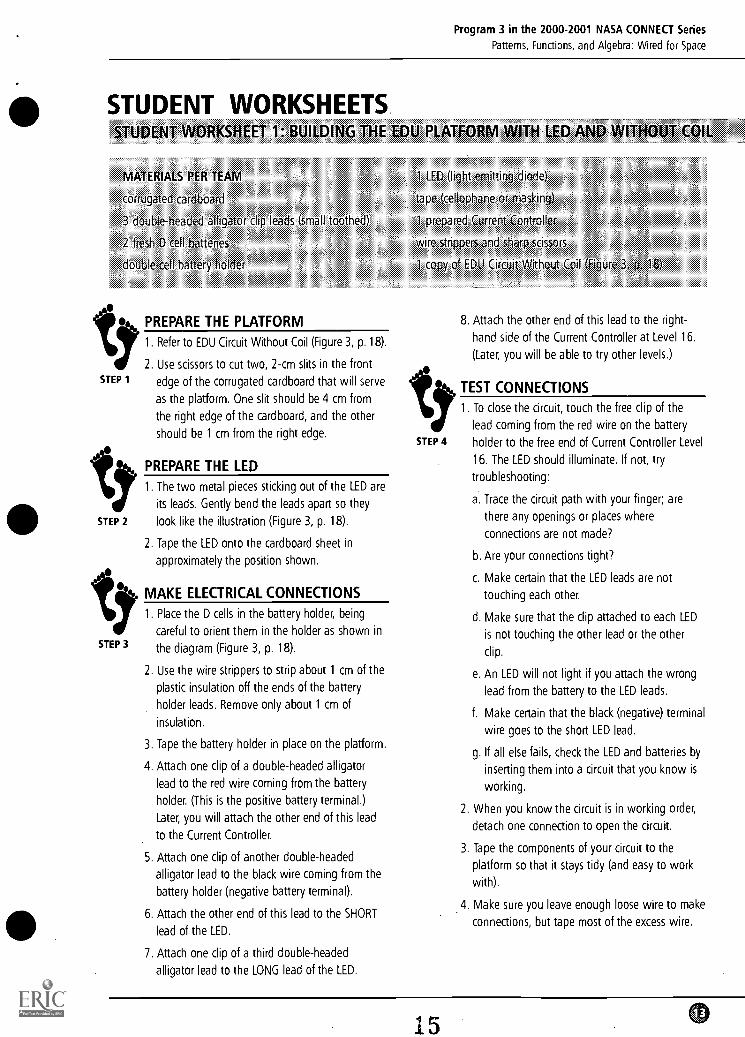
STUDENT WORKSHEETSSTUDENT WORKSHEET 1: BUILDING THE
MATERIALS PER TEAM
corrugated cardboard
3 double-headed alligator clip leads (small toothed)
2 fresh 0 cell batteries
double-cell battery holder
EDU PLATFORM WITH LED AND W THOUT COIL
1 LED (light emitting diode)
tape (cellophane or masking)
1 prepared Current Controller
wire strippers and sharp scissors
1 copy of EDU Circuit Without Coil (Figure 3, p 18)
PREPARE THE PLATFORM
1. Refer to EDU Circuit Without Coil (Figure 3, p.18).
2. Use scissors to cut two, 2-cm slits in the frontSTEP 1 edge of the corrugated cardboard that will serve
as the platform. One slit should be 4 cm from
the right edge of the cardboard, and the other
should be 1 cm from the right edge.
PREPARE THE LED
1. The two metal pieces sticking out of the LED are
its leads. Gently bend the leads apart so they
STEP 2 look like the illustration (Figure 3, p. 18).
2. Tape the LED onto the cardboard sheet in
approximately the position shown.
STEP 3
MAKE ELECTRICAL CONNECTIONS
1. Place the D cells in the battery holder, being
careful to orient them in the holder as shown in
the diagram (Figure 3, p. 18).
2. Use the wire strippers to strip about 1 cm of the
plastic insulation off the ends of the battery
holder leads. Remove only about 1 cm of
insulation.
3. Tape the battery holder in place on the platform.
4. Attach one clip of a double-headed alligator
lead to the red wire coming from the battery
holder. (This is the positive battery terminal.)
Later, you will attach the other end of this lead
to the Current Controller.
5. Attach one clip of another double-headed
alligator lead to the black wire coming from the
battery holder (negative battery terminal).
6. Attach the other end of this lead to the SHORT
lead of the LED.
7. Attach one clip of a third double-headed
alligator lead to the LONG lead of the LED.
STEP 4
8. Attach the other end of this lead to the right-
hand side of the Current Controller at Level 16.
(Later, you will be able to try other levels.)
TEST CONNECTIONS
1 To close the circuit, touch the free clip of the
lead coming from the red wire on the battery
holder to the free end of Current Controller Level
16. The LED should illuminate. If not, try
troubleshooting:
a. Trace the circuit path with your finger; are
there any openings or places where
connections are not made?
b. Are your connections tight?
c. Make certain that the LED leads are not
touching each other.
d. Make sure that the clip attached to each LED
is not touching the other lead or the other
clip.
e. An LED will not light if you attach the wrong
lead from the battery to the LED leads.
f. Make certain that the black (negative) terminal
wire goes to the short LED lead.
g. If all else fails, check the LED and batteries by
inserting them into a circuit that you know is
working.
2. When you know the circuit is in working order,
detach one connection to open the circuit.
3. Tape the components of your circuit to the
platform so that it stays tidy (and easy to work
with).
.4. Make sure you leave enough loose wire to make
connections, but tape most of the excess wire.
15
Program 3 in the 2000-2001 NASA CONNECT Series
Patterns, Functions, and Algebra: Wired for Space
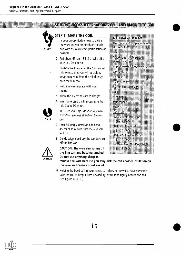
STUDENT WORKSHEET 2: ADDING COIL AND MAGNET TO EDU
STEP 1: MAKE THE COIL
STEP 1
NOTE
CAUTION
1. In your group, decide how to divide
the work so you can finish as quickly
and with as much team participation as
possible.
2. Pull about 45 cm (18 in.) of wire off a
wire roll. Do not cut.
3. Position the film can at the 45th cm of
this wire so that you will be able to
wrap more wire from the roll directly
onto the film can.
4. Hold the wire in place with your
thumb.
5. Allow the 45 cm of wire to dangle.
6. Wrap wire onto the film can from the
roll. Count 50 wraps.
NOTE: As you wrap, use your thumb to
hold down any wire already on the film
can.
7. After 50 wraps, unroll an additional
45 cm or so of wire from the wire roll
and cut.
8. Gently wiggle and pry the wrapped coil
off the film can.
CAUTION: The wire can spring offthe film can and become tangled.Do not use anything sharp toremove the wire because you may nick the red enamel insulation onthe wire and cause a short circuit.
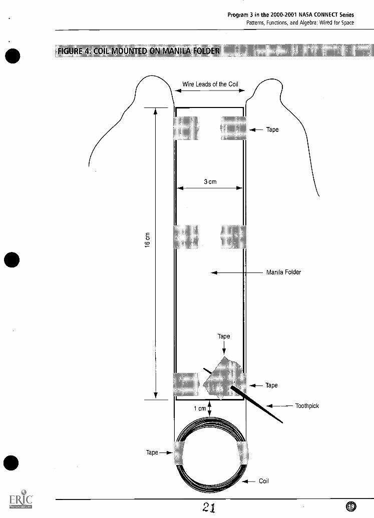
9. Holding the freed coil in your hands so it does not unwind, have someone
tape the coil to keep it from unwinding. Wrap tape tightly around the coil
(see Figure 4, p. 19).
MATERIALS PER TEAM
The prepared EDU platform with
LED circuit
box
1 additional double-sided
alligator clip lead
strip of manila folder, 3cm xl6cm
toothpick
mm ruler
magnet wire
35-mm film cannister
tape
cow magnet
sandpaper
scissors
Copies of
Overview of EDU Setup
(Figure 1, page 16)
EDU Circuit with Coil
(Figure 2, page 17)
EDU Circuit Without Coil(Figure 3, page 18)
Coil Mounted on Manila Folder
(Figure 4, page 19)
1 6
0
Program 3 in the 2000-2001 NASA CONNECT Series
Patterns, Functions, and Algebra: Wired for Space
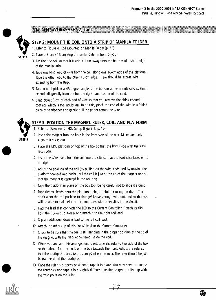
STUDENT WORKSHEET 2, cont
yt STEP 2: MOUNT THEoCOIL ONTOI A STRIP. OF. MANILA FOLDER
STEP2. Place a 3-cm x 16-cm strip of manila folder in front of you.
2
STEP 3
3. Position the coil so that it is about 1 cm away from the bottom of a short edge
of the manila strip.
4. Tape one long lead of wire from the coil along one 16-cm edge of the platform.
Tape the other lead to the other 16-cm edge. There should be excess wire
extending from the strip.
5. Tape a toothpick at a 45 degree angle to the bottom of the manila card so that it
extends diagonally from the bottom right-hand corner of the card.
6. Sand about 3 cm of each end of wire so that you remove the shiny enamel
coating, which is the insulation. To do this, pinch the end of the wire in a folded
piece of sandpaper and gently pull the paper across the wire.
STEP 3: POSITION THE MAGNET, RULER, COIL, AND PLATFORM
1. Refer to Overview of EDU Setup (Figure 1, p. 16).
2. Insert the magnet into the hole in the front side of the box. Make sure only
4 cm of it sticks out.
3. Place the EDU platform on top of the box so that the front (side with the slits)
faces you.
4. Insert the wire leads from the coil into the slits so that the toothpick faces off to
the right.
5. Adjust the position of the coil (by pulling on the wire leads and by moving the
platform forward and back) until the coil is just at the tip of the magnet and so
that the magnet is centered in the coil ring.
6. Tape the platform in place on the box top, being careful not to slide it around.
7. Tape the coil leads onto the platform, being careful not to tug on them. You
don't want the coil position to change! Leave enough wire untaped so that you
will be able to make electrical connections with other clips in the circuit.
8. Find the lead that connects the LED to the Current Controller. Detach its clip
from the Current Controller and attach it to the right coil lead.
9. Clip an additional double lead to the left coil lead.
10. Attach the other clip of this "new" lead to the Current Controller.
11. Check to be sure that the coil is still hanging in the proper position at the tip of
the magnet with the magnet centered inside the coil.
12. When you are sure this arrangement is set, tape the ruler to the side of the box
so that about 4 cm extends off the box towards the front. Adjust the ruler so
that the toothpick points to the zero point on the ruler. The ruler should be just
below the tip of the toothpick.
13. Once the ruler is properly positioned, tape it in place. You may need to untape
the toothpick and tape it in a slightly different position to get it to line up with
the zero point on the ruler.
1
Program 3 in the 2000-2001 NASA CONNECT Series
Patterns, Functions, and Algebra: Wired for Space
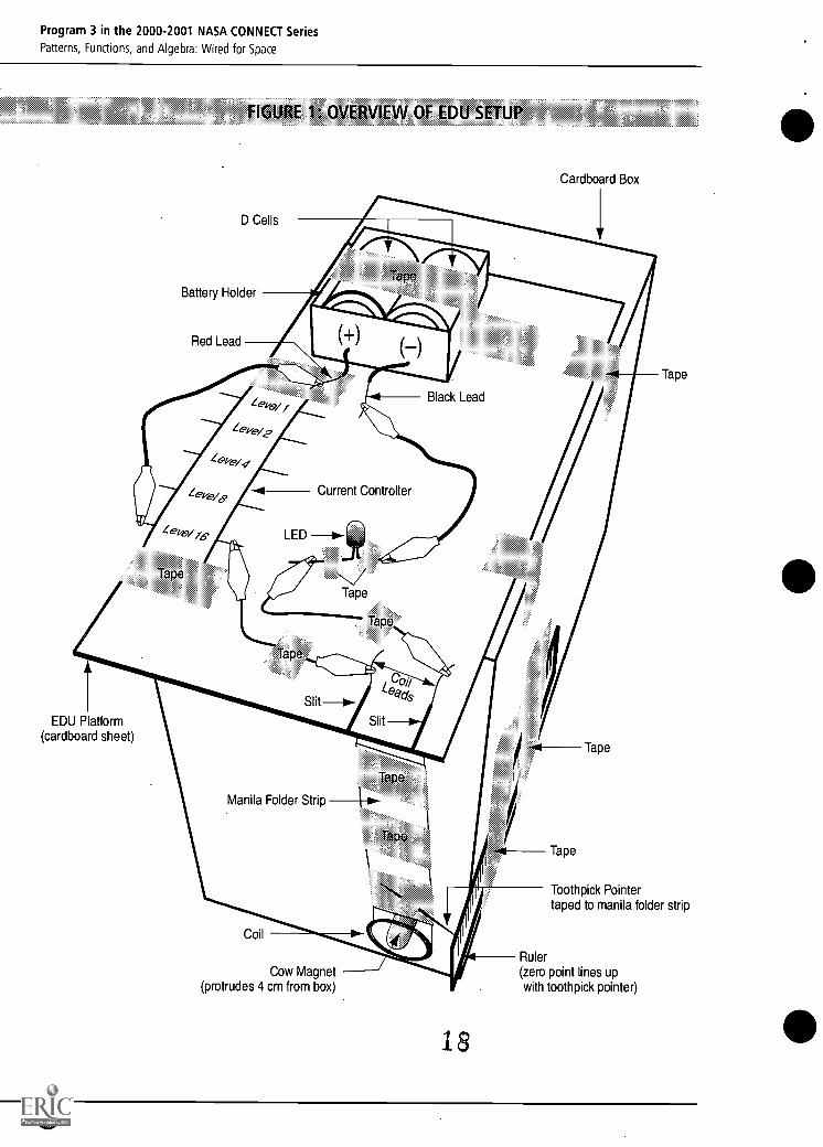
FIGURE 1: OVERVIEW OF EDU SETUP
D Cells
Battery Holder
Red Lead
Cardboard Box
Black Lead
Zep67.49
Lep -0/76-,
Tape
Current Controller
Tape
Tape
EDU Platform(cardboard sheet)
Tape
Manila Folder Strip
Coil
Cow Magnet(protrudes 4 cm from box)
18
Tape
Tape
Tape
Toothpick Pointertaped to manila folder strip
Ruler(zero point lines upwith toothpick pointer)
Program 3 in the 2000-2001 NASA CONNECT Series
Patterns, Functions, and Algebra: Wired for Space
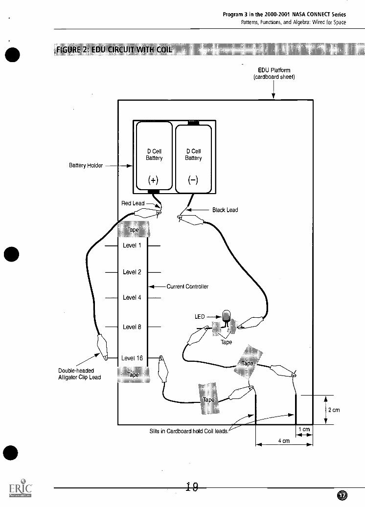
FIGURE 2: EDU CIRCUIT WITH COIL
Battery Holder
Double-headedAlligator Clip Lead
EDU Platform(cardboard sheet)
D CellBattery
(+)
D CellBattery
()
Red Lead
Tape
Level 1
Level 2
Level 4
Level 8
Level 16
Tape
-41Current Controller
Black Lead
LED --o-
Tape
Tape
Slits in Cardboard hold Coil leads.
4 cm
12 cm
e
Program 3 in the 2000-2001 NASA CONNECT Series
Patterns, Functions, and Algebra: Wired for Space
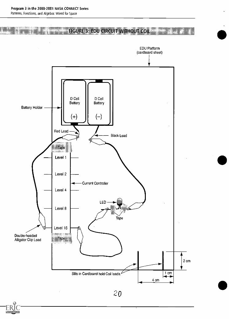
Battery Holder
Double-headedAlligator Clip Lead
FIGURE 3: EDU CIRCUIT WITHOUT COIL
EDU Platform(cardboard sheet)
'I'
D CellBattery
(+)
D CellBattery
(-)
Red Lead Thik
Tape
Level 1
Level 2
Level 4
Level 8
Level 16
Tape
-4Current Controller
Black Lead
LED 40-
Tape
Slits in Cardboard hold Coil leads.
-4*
1 cm
4 cm
12 cm
o
Program 3 in the 2000-2001 NASA CONNECT Series
Patterns, Functions, and Algebra: Wired for Space
FIGURE 4: COIL MOUNTED ON MANILA FOLDER
Tape
Wire Leads of the Coil
3 cm
1 cm
Tape
Tape
Manila Folder
Tape
Toothpick
21
Program 3 in the 2000-2001 NASA CONNECT Series
Patterns, Functions, and Algebra: Wired for Space
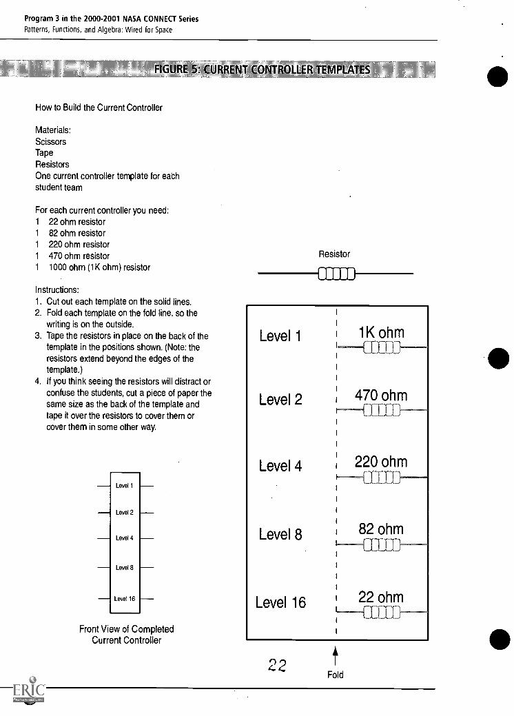
FIGURE 5: CURRENT CONTROLLER TEMPLATES
How to Build the Current Controller
Materials:
ScissorsTape
ResistorsOne current controller template for eachstudent team
For each current controller you need:1 22 ohm resistor1 82 ohm resistor1 220 ohm resistor1 470 ohm resistor1 1000 ohm (1K ohm) resistor
Instructions:
1. Cut out each template on the solid lines.2. Fold each template on the fold line, so the
writing is on the outside.3. Tape the resistors in place on the back of the
template in the positions shown. (Note: theresistors extend beyond the edges of thetemplate.)
4. If you think seeing the resistors will distract orconfuse the students, cut a piece of paper thesame size as the back of the template andtape it over the resistors to cover them orcover them in some other way.
Level 1
Level 2
Level 4
Level 8
Level 16
Front View of CompletedCurrent Controller
Resistor
Level 1
Level 2
Level 4
Level 8
Level 16
1K ohmIIID-470 ohm
220 ohmfilLE
82 ohmCOM
22 ohmLFTIE
4°2Fold
Program 3 in the 2000-2001 NASA CONNECT Series
Patterns, Functions, and Algebra: Wired for Space
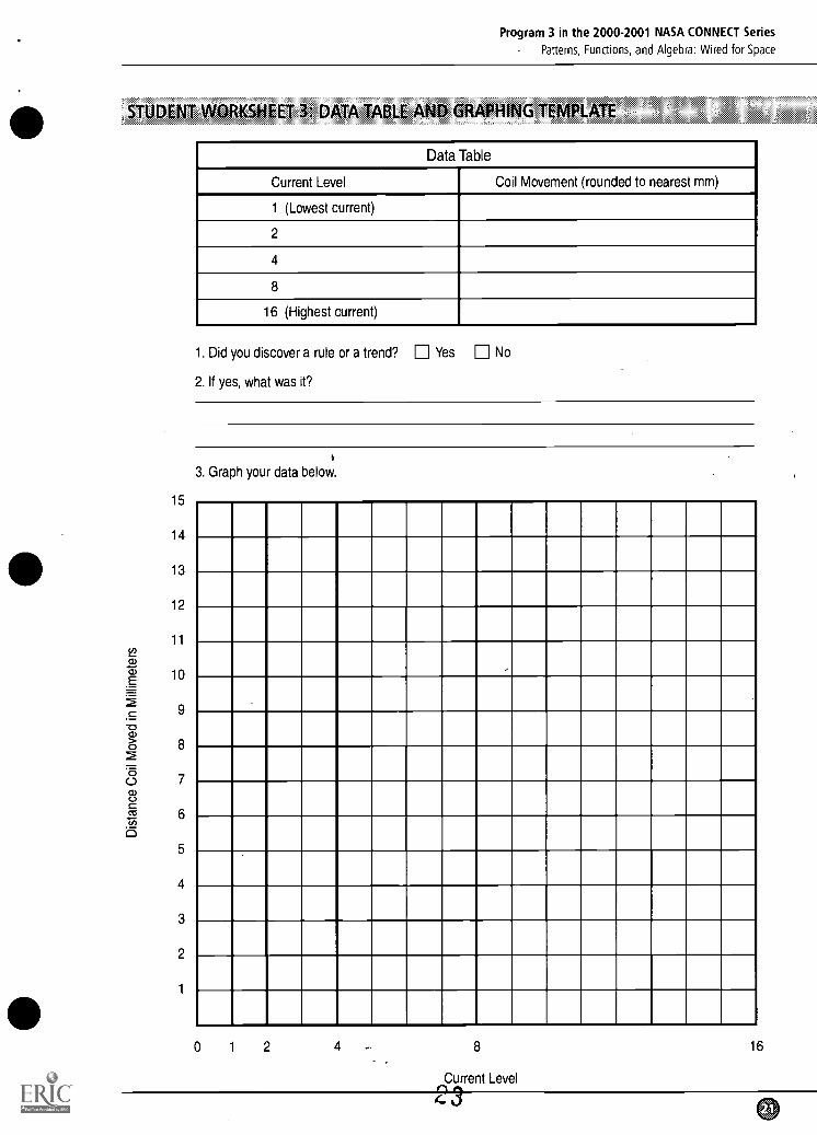
STUDENT WORKSHEET 3: DATA TABLE AND GRAPHING TEMPLATE
15
14
13
12
11
10
9
8
7
6
5
4
3
2
1
Data Table
Current Level Coil Movement (rounded to nearest mm)
1 (Lowest current)
2
4
8
16 (Highest current)
1. Did you discover a rule or a trend? 0 Yes El No
2. If yes, what was it?
e
3. Graph your data below.
0 1 2 4 8
Current Level
16
4 o
Program 3 in the 2000-2001 NASA CONNECT Series
Patterns, Functions, and Algebra: Wired for Space
15
14
13
12
11
10
9
8
7
6
5
4
3
2
1
SAMPLE DATA TABLE At 5 6RAPHii6 TEMPLATE
Data Table
Current Level Coil Movement (rounded to nearest mm)
1 (Lowest current) 1
2 24 38 e
16 (Highest current) 1 5
1. Did you discover a rule or a trend? 0 Yes El No
2.If yes, what was it?
3. Graph your data below.
0 1 2 4 8
Current Level2 4
16
Program 3 in the 2000-2001 NASA CONNECT Series
Patterns, Functions, and Algebra: Wired for Space
STUDENT CUE CARDS
1. What kind of test did they use?
2. Were there any patterns in the results?
3. What kind of graph resulted from the data?
1. How was algebra used to find the solution?
2. How are arrays used in algebra?
3. What algebraic equation shows that voltage is related to current?
Program 3 in the 2000-2001 NASA CONNECT Series
Patterns, Functions, and Algebra: Wired for Space
To access IPPEX, visit Norbert's lab,
http://connect.larc.nasa.gov/wired/lab.html
THE WEB ACTIVITY
THE ACTIVITY,
The Internet Plasma Physics Education eXperience (IPPEX) is an interactive on-line
activity developed by the Princeton University Plasma Physics Laboratory, Princeton,
New Jersey. IPPEX has created several interactive physics modules, including one on
electricity and magnetism. This module will introduce many of the basic concepts
involved with electricity and magnetism, such as static charge, *moving charge,
voltage, resistance, and current. This site combines multimedia with built-in
interactive exercises to help students better understand the concepts of electricity
and magnetism. For example, IPPEX invites students to rub a balloon on a wool
sweater to learn about static electricity, and later, to manipulate slider bars to see
what happens to similar static charges between balloons. Students are also
introduced to the concept of what makes an electrical circuit and to the
relationships between magnetic fields and electricity.
To access IPPEX, visit Norbert's lab http://connect.larc.nasa.gov/wired/lab.html.
Norbert's lab contains links to additional on-line resources and a link to Career
Corner, featuring researchers and NASA CONNECT team members. New this season
is the NASA CONNECT Lab Manager The Lab Manager offers assistance to teachers
who would like to get the most from the site.
NATIONAL STANDARDS
TECHNOLOGY STANDARDS
Develop positive attitudes toward technology uses that support lifelong learning,
collaboration, personal pursuits, and productivity.
Use technology tools to enhance learning, increase productivity, and promote
creativity.
SCIENCE STANDARDS
Light, heat, electricity, and magnetism
Transfer of energy
MATHEMATICS STANDARDS
Use mathematical models to represent and understand quantitative relationships.
Analyze change in various contexts.
Develop and evaluate inferences and predictions that are based on data.
Apply and adapt a variety of appropriate strategies to solve problems.
INSTRUCTIONAL OBJECTIVES
Students will
use critical thinking skills and problem-solving skills to gain an understanding of
electricity and magnetism.
use technology to further their problem-solving skills and understanding of
electricity and magnetism.
26
Program 3 in the 2000-2001 NASA CONNECT Series
Patterns, Functions, and Algebra: Wired for Space
RESOURCES
Books, PAMPLEtS, AND PERIODICALS
Challand, Helen J., Experiments with Magnets. 1986: Canada and USA, Ragensteiner
Publishing Enterprises, Inc. Introductory level explorations of magnets and
magnetism.
Hewitt, Paul G., Conceptual Physics. 1985: Boston, Little Brown and Company. (A
good teacher resource, this is a physics textbook written in an accessible style.)
Scientific American, Spring 1999 Special Edition. Scientific American Presents the Future
of Space Exploration: A Guide to the Voyages Unveiling the Cosmos. Includes an
extensive section highlighting the cutting edge of space flight technology and
research. (ISSN 1048-0943), Volume 10, Number 1, Spring 1999. Published quarterly
by Scientific American, Inc., 415 Madison Avenue, New York, NY 10017-1111.
Space Transportation: Past, Present and Future. CD-ROM Reference Number 400.1-29.
To order, contact NASA CORE 440/775-1400; email [email protected] or visit the
website: http://core.nasa.gov
Space Basics: An introduction to the physics of orbiting satellites. NASA Liftoff to
Learning Series, Videotape Reference Number EV-1997-07-010HQ. (To preview
online or order, contact NASA CORE 440/775-1400; email [email protected] or
visit the website: http://core,nasa.gov)
Tethered Satellites Part II: Electrical Circuits in Space/The Electrodynamics of the Tethered
Satellite. NASA Liftoff to Learning Series Videotape Reference Number EV-1997-07-
011HQ. Describes how the current is produced in a space tether used for
propulsion. (To preview online or order, contact NASA CORE 440/775-1400; email
[email protected] or vi.sit the website: http://core.nasa.gov)
Vecchione, Glen, Magnet Science. 1995: New York, Sterling Publishing Co., Inc.
Activities and information about magnetism for middle school students and beyond.
2 7
Program 3 in the 2000-2001 NASA CONNECT Series
Patterns, Functions, and Algebra: Wired for Space
WEB SITES
NASA Earth-to-Orbit Engineering Design Challenges: Electrodynamic Propulsion.
Pending publication. A 2-3 week design challenge about electrodynamic
propulsion. http:///eto.nasa.gov
Brief introduction to MagLev with links to other resources on this topic.
http://kids.msfc.nasa.gov/News/2000/News-Maglev.asp
Electricity Misconceptions In K-6 Textbooks by William J. Beaty. Resource for teachers,
addressing helpful and not-so-helpful ways in which "electricity" is described and
demonstrated for students.
http://www.amasci.com/miscon/eleca.html#electron
An accessible, simply written article introducing the idea of using tethers in space.
http://liftoff.msfc.nasa.gov/academy/TETHER/tethers.html
Description of the Pro-SEDS mission in the form of a NASA Science News article,
Plugged Into Space.
http://www.science.nasa.gov/newhome/headlines/astl 5oct98_1.htm
Historical look at William Gilbert, later physician to Queen Elizabeth I of England
and his pioneering study of magnetism that gave the first rational explanation to
the ability of the compass needle to point north-south.
http://www-spof.gsfc.nasa.gov/earthmag/demagint.htm
28
U.S. Department of EducationOffice of Educational Research and Improvement (OERI)
National Library of Education (NLE)Educational Resources Information Center (ERIC)
NOTICE
Reproduction Basis
ERIC
This document is covered by a signed "Reproduction Release(Blanket)" form (on file within the ERIC system), encompassing allor classes of documents from its source organization and, therefore,does not require a "Specific Document" Release form.
This document is Federally-funded, or carries its own permission toreproduce, or is otherwise in the public domain and, therefore, maybe reproduced by ERIC without a signed Reproduction Release form(either "Specific Document" or "Blanket").
EFF-089 (3/2000)