report on heat production during preliminary tests … on heat production during preliminary tests...
TRANSCRIPT
Report on heat production during preliminary tests on the
Rossi “Ni-H” reactor
Dr. Giuseppe Levi
In this first and preliminary document are reported the heat production measures done during two short tests done on December 16 2010 [Test 1] and January 14 2011 [Test 2].
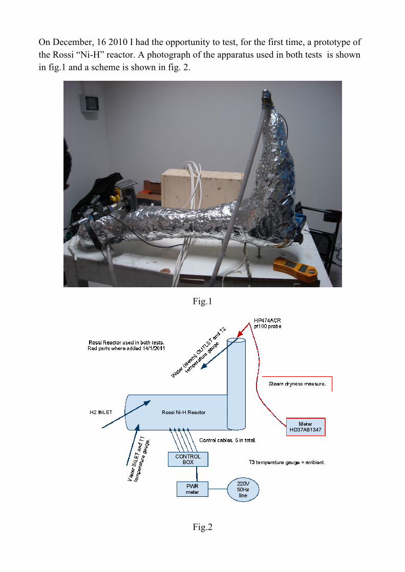
On December, 16 2010 I had the opportunity to test, for the first time, a prototype of the Rossi “Ni-H” reactor. A photograph of the apparatus used in both tests is shown in fig.1 and a scheme is shown in fig. 2.
Fig.1
Fig.2
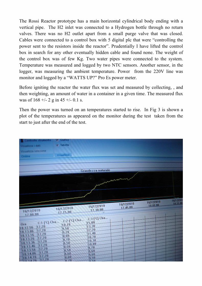
The Rossi Reactor prototype has a main horizontal cylindrical body ending with a vertical pipe. The H2 inlet was connected to a Hydrogen bottle through no return valves. There was no H2 outlet apart from a small purge valve that was closed. Cables were connected to a control box with 5 digital plc that were “controlling the power sent to the resistors inside the reactor”. Prudentially I have lifted the control box in search for any other eventually hidden cable and found none. The weight of the control box was of few Kg. Two water pipes were connected to the system. Temperature was measured and logged by two NTC sensors. Another sensor, in the logger, was measuring the ambient temperature. Power from the 220V line was monitor and logged by a “WATTS UP?” Pro Es power meter.
Before igniting the reactor the water flux was set and measured by collecting, , and then weighting, an amount of water in a container in a given time. The measured flux was of 168 +/- 2 g in 45 +/- 0.1 s.
Then the power was turned on an temperatures started to rise. In Fig 3 is shown a plot of the temperatures as appeared on the monitor during the test taken from the start to just after the end of the test.
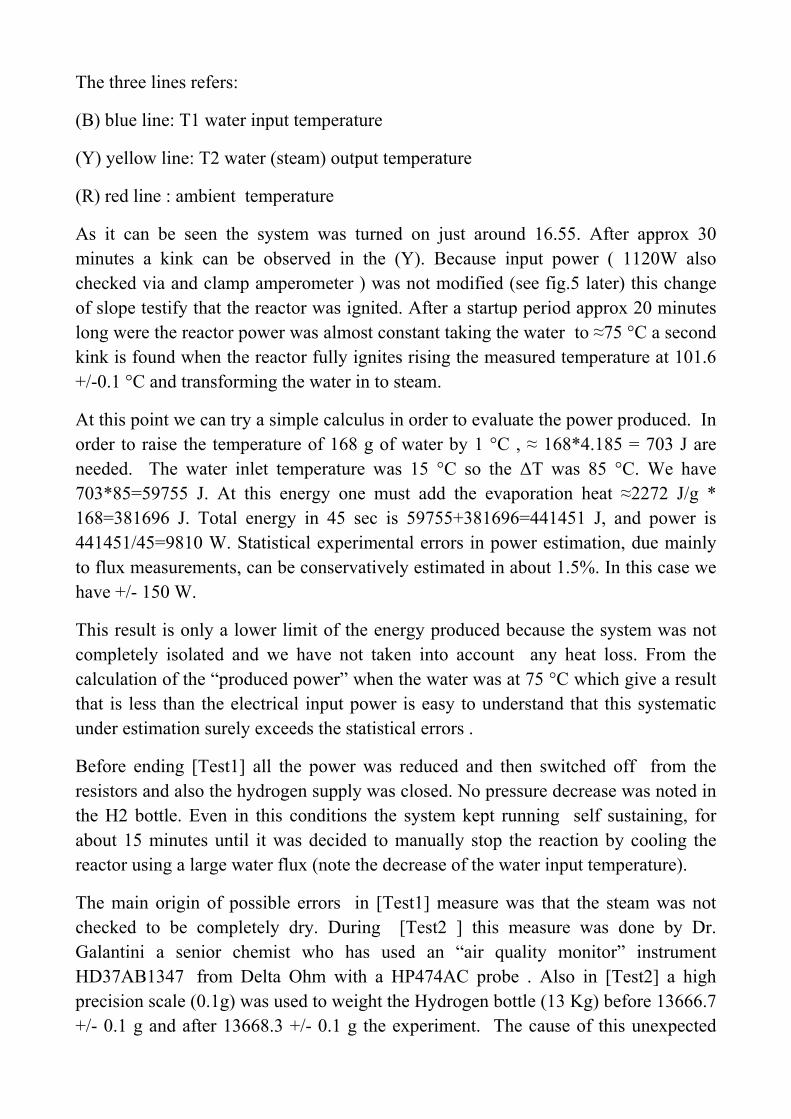
The three lines refers:
(B) blue line: T1 water input temperature
(Y) yellow line: T2 water (steam) output temperature
(R) red line : ambient temperature
As it can be seen the system was turned on just around 16.55. After approx 30 minutes a kink can be observed in the (Y). Because input power ( 1120W also checked via and clamp amperometer ) was not modified (see fig.5 later) this change of slope testify that the reactor was ignited. After a startup period approx 20 minutes long were the reactor power was almost constant taking the water to ≈75 °C a second kink is found when the reactor fully ignites rising the measured temperature at 101.6 +/-0.1 °C and transforming the water in to steam.
At this point we can try a simple calculus in order to evaluate the power produced. In order to raise the temperature of 168 g of water by 1 °C , ≈ 168*4.185 = 703 J are needed. The water inlet temperature was 15 °C so the ∆T was 85 °C. We have 703*85=59755 J. At this energy one must add the evaporation heat ≈2272 J/g * 168=381696 J. Total energy in 45 sec is 59755+381696=441451 J, and power is 441451/45=9810 W. Statistical experimental errors in power estimation, due mainly to flux measurements, can be conservatively estimated in about 1.5%. In this case we have +/- 150 W.
This result is only a lower limit of the energy produced because the system was not completely isolated and we have not taken into account any heat loss. From the calculation of the “produced power” when the water was at 75 °C which give a result that is less than the electrical input power is easy to understand that this systematic under estimation surely exceeds the statistical errors .
Before ending [Test1] all the power was reduced and then switched off from the resistors and also the hydrogen supply was closed. No pressure decrease was noted in the H2 bottle. Even in this conditions the system kept running self sustaining, for about 15 minutes until it was decided to manually stop the reaction by cooling the reactor using a large water flux (note the decrease of the water input temperature).
The main origin of possible errors in [Test1] measure was that the steam was not checked to be completely dry. During [Test2 ] this measure was done by Dr. Galantini a senior chemist who has used an “air quality monitor” instrument HD37AB1347 from Delta Ohm with a HP474AC probe . Also in [Test2] a high precision scale (0.1g) was used to weight the Hydrogen bottle (13 Kg) before 13666.7 +/- 0.1 g and after 13668.3 +/- 0.1 g the experiment. The cause of this unexpected
rise was traced to be the remnant of piece of adhesive tape used to fix the bottle during the experiment. After careful examination of the tape the weight loss was evaluated to be <1g. This is far less the expected weight loss due to chemical burning. In fact 1g of H can produce (max) 128 kJ. In [Test2] the power measured was 12686 +/- 211 W for about 40 min with a water flux 146.4g +/- 0.1 per 30 +/- 0.5 s. The mean input power during the test was 1022 W. This means that 11664 * 40 * 60 = 27993600 J were produced. As stated before this is only a lower limit.
Dividing this number by 128kJ a weight of 218g is obtained, two order of magnitude larger than the H consumption observed.
As a prudential check the reactor was lifted to seek any eventually hidden power cord. None was found.
During the test the main resistor, used to ignite the reaction, failed due to defective welding. Even in that condition the reactor successfully started operation using the other resistors but the duration of the experiment in full power (≈40 min) was “too short” to observe a self sustaining reaction.
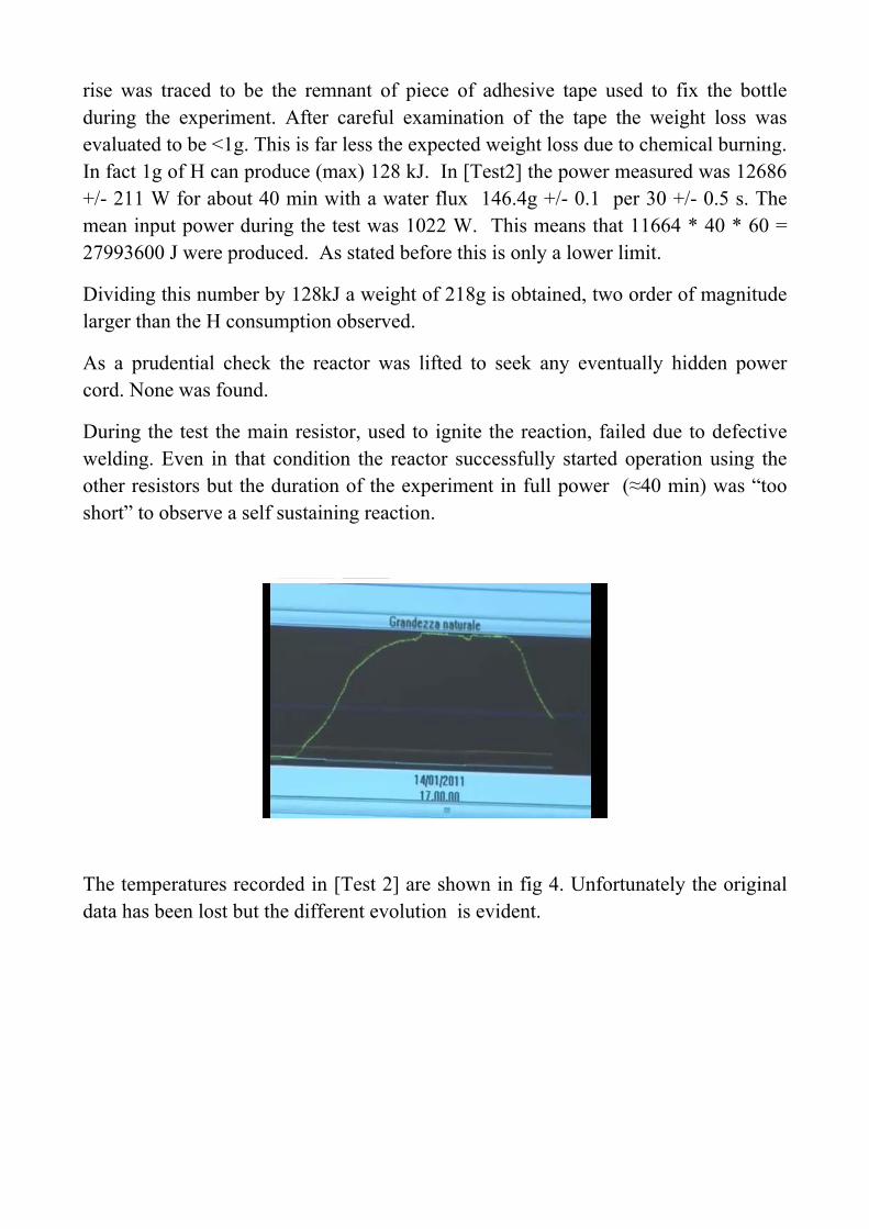
The temperatures recorded in [Test 2] are shown in fig 4. Unfortunately the original data has been lost but the different evolution is evident.
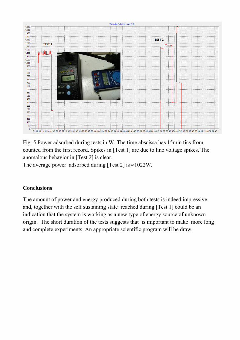
Fig. 5 Power adsorbed during tests in W. The time abscissa has 15min tics from counted from the first record. Spikes in [Test 1] are due to line voltage spikes. The anomalous behavior in [Test 2] is clear. The average power adsorbed during [Test 2] is ≈1022W.
Conclusions
The amount of power and energy produced during both tests is indeed impressive and, together with the self sustaining state reached during [Test 1] could be an indication that the system is working as a new type of energy source of unknown origin. The short duration of the tests suggests that is important to make more long and complete experiments. An appropriate scientific program will be draw.
Dott. Bianchini DavidPhysics Department - University of BolognaViale Berti Pichat 6/2 - 40127 Bologna
Kind attention ofEFA srl
Via Marsili 440100 Bologna
c.f. e P.iva: 02826781208
Bologna 21/01/2011
Experimental evaluation, for radiation protection purpose, of photon and neutron radiation field during the public presentation of the
prototype called "Energy Amplifier"
PREFACE
On 14/01/11 at the GM System plant of Via dell'Elettricista 16 in Bologna, I performed radiation field measurements for radiation protection purposes as per your request of 09/11/10.This report is therefore about the evaluation of the photon and neutron radiation field near the prototype called “Energy Amplifier” during it's public presentation.
The process, the geometry and the materials used for the production of energy inside the “Energy Amplifier” are unknowns that I'm not aware of. Environmental monitoring is defined temporally before, during and after the test in question
The field evaluation can not relate to criteria of functionality of the system and can not be used for comparison in systems different from this one, in the process, in the geometry or in the construction materials used.
TIME DESCRIPTION OF THE TEST
The test has been conducted without interruptions in the measures presented below, which therefore represent, to all intents and purposes, a continuous monitoring of the photon field and of the neutron field samples as summarized in table:
ID Phase Start time End time 0 External environmental background 13:10 13:201 Before ignition 15:45 16:222 Ignition 16:22 16:453 Stability 16:45 17:254 Switching off 17:25 17:555 After switching off 17:55 19:00
Table 1: Time phases of the present measures during the presentation of the “Energy Amplifier” .
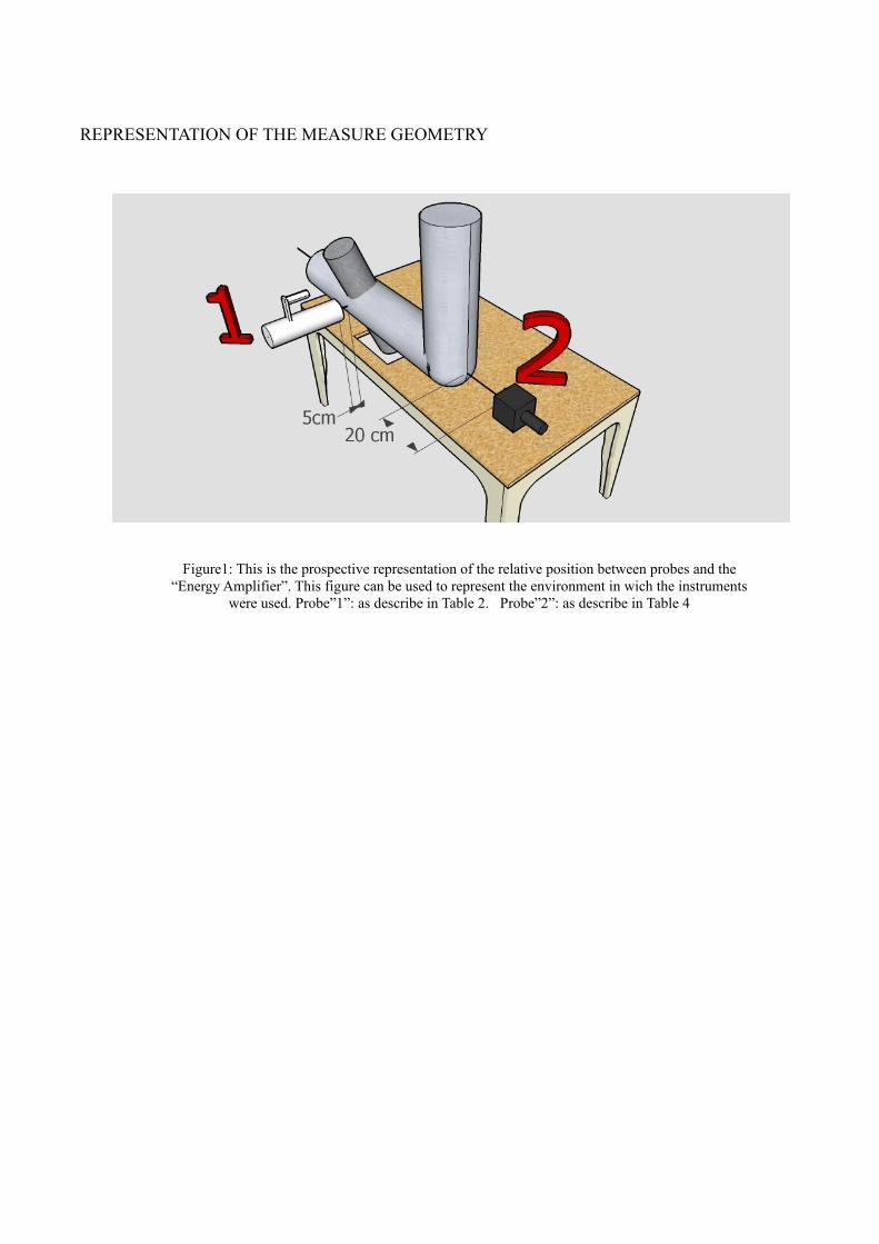
REPRESENTATION OF THE MEASURE GEOMETRY
Figure1: This is the prospective representation of the relative position between probes and the “Energy Amplifier”. This figure can be used to represent the environment in wich the instruments
were used. Probe”1”: as describe in Table 2. Probe”2”: as describe in Table 4
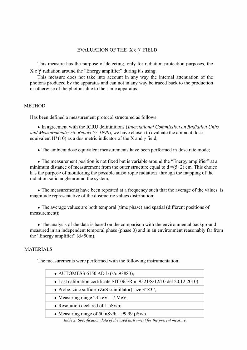
EVALUATION OF THE X e γ FIELD
This measure has the purpose of detecting, only for radiation protection purposes, the
X e γ radiation around the “Energy amplifier” during it's using.This measure does not take into account in any way the internal attenuation of the
photons produced by the apparatus and can not in any way be traced back to the production or otherwise of the photons due to the same apparatus.
METHOD
Has been defined a measurement protocol structured as follows:
● In agreement with the ICRU defininitions (International Commission on Radiation Units and Measurements; rif. Report 57-1998), we have chosen to evaluate the ambient dose equivalent H*(10) as a dosimetric indicator of the X and γ field;
● The ambient dose equivalent measurements have been performed in dose rate mode;
● The measurement position is not fixed but is variable around the “Energy amplifier” at a minimum distance of measurement from the outer structure equal to d =(5±2) cm. This choice has the purpose of monitoring the possible anisotropic radiation through the mapping of the radiation solid angle around the system;
● The measurements have been repeated at a frequency such that the average of the values is magnitude representative of the dosimetric values distribution;
● The average values are both temporal (time phase) and spatial (different positions of measurement);
● The analysis of the data is based on the comparison with the environmental background measured in an independent temporal phase (phase 0) and in an environment reasonably far from the “Energy amplifier” (d>50m).
MATERIALS
The measurements were performed with the following instrumentation:
● AUTOMESS 6150 AD-b (s/n 93883);
● Last calibration certificate SIT 065/R n. 9521/S/12/10 del 20.12.2010);
● Probe: zinc sulfide (ZnS scintillator) size 3”×3”;
● Measuring range 23 keV – 7 MeV;
● Resolution declared of 1 nSv/h;
● Measuring range of 50 nSv/h – 99.99 μSv/h. Table 2: Specification data of the used instrument for the present measure.
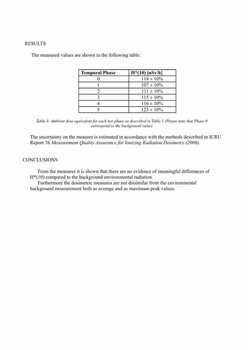
RESULTS
The measured values are shown in the following table:
Temporal Phase H*(10) [nSv/h]
0 118 ± 10%1 107 ± 10%2 111 ± 10%3 115 ± 10%4 116 ± 10%5 123 ± 10%
Table 3: Ambient dose equivalent for each test phase as described in Table 1 (Please note that Phase 0 correspond to the background value)
The uncertainty on the measure is estimated in accordance with the methods described in ICRU Report 76 Measurement Quality Assurance for Ionizing Radiation Dosimetry (2006).
CONCLUSIONS
From the measures it is shown that there are no evidence of meaningful differences of H*(10) compared to the background environmental radiation.
Furthermore the dosimetric measures are not dissimilar from the environmental background measurement both as average and as maximum peak values.
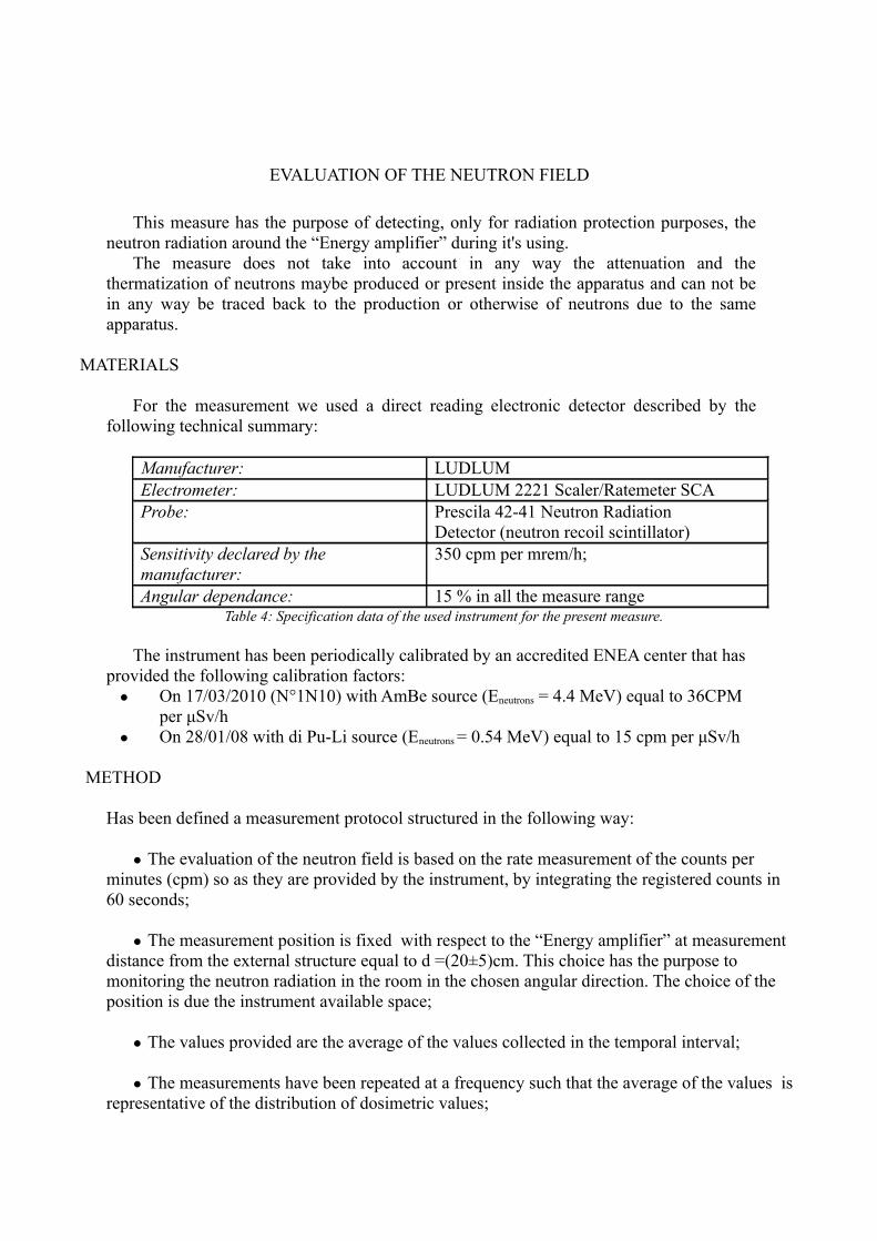
EVALUATION OF THE NEUTRON FIELD
This measure has the purpose of detecting, only for radiation protection purposes, the neutron radiation around the “Energy amplifier” during it's using.
The measure does not take into account in any way the attenuation and the thermatization of neutrons maybe produced or present inside the apparatus and can not be in any way be traced back to the production or otherwise of neutrons due to the same apparatus.
MATERIALS
For the measurement we used a direct reading electronic detector described by the following technical summary:
Manufacturer: LUDLUMElectrometer: LUDLUM 2221 Scaler/Ratemeter SCAProbe: Prescila 42-41 Neutron Radiation
Detector (neutron recoil scintillator) Sensitivity declared by the manufacturer:
350 cpm per mrem/h;
Angular dependance: 15 % in all the measure rangeTable 4: Specification data of the used instrument for the present measure.
The instrument has been periodically calibrated by an accredited ENEA center that has provided the following calibration factors: ● On 17/03/2010 (N°1N10) with AmBe source (Eneutrons = 4.4 MeV) equal to 36CPM
per μSv/h● On 28/01/08 with di Pu-Li source (Eneutrons = 0.54 MeV) equal to 15 cpm per μSv/h
METHOD
Has been defined a measurement protocol structured in the following way: ● The evaluation of the neutron field is based on the rate measurement of the counts per
minutes (cpm) so as they are provided by the instrument, by integrating the registered counts in 60 seconds;
● The measurement position is fixed with respect to the “Energy amplifier” at measurement distance from the external structure equal to d =(20±5)cm. This choice has the purpose to monitoring the neutron radiation in the room in the chosen angular direction. The choice of the position is due the instrument available space;
● The values provided are the average of the values collected in the temporal interval;
● The measurements have been repeated at a frequency such that the average of the values is representative of the distribution of dosimetric values;
● The analysis of the data is based on the comparison with the background measured in an independent temporal phase (phase 0) and in an environment reasonably far from the “Energy amplifier” (d>50m).
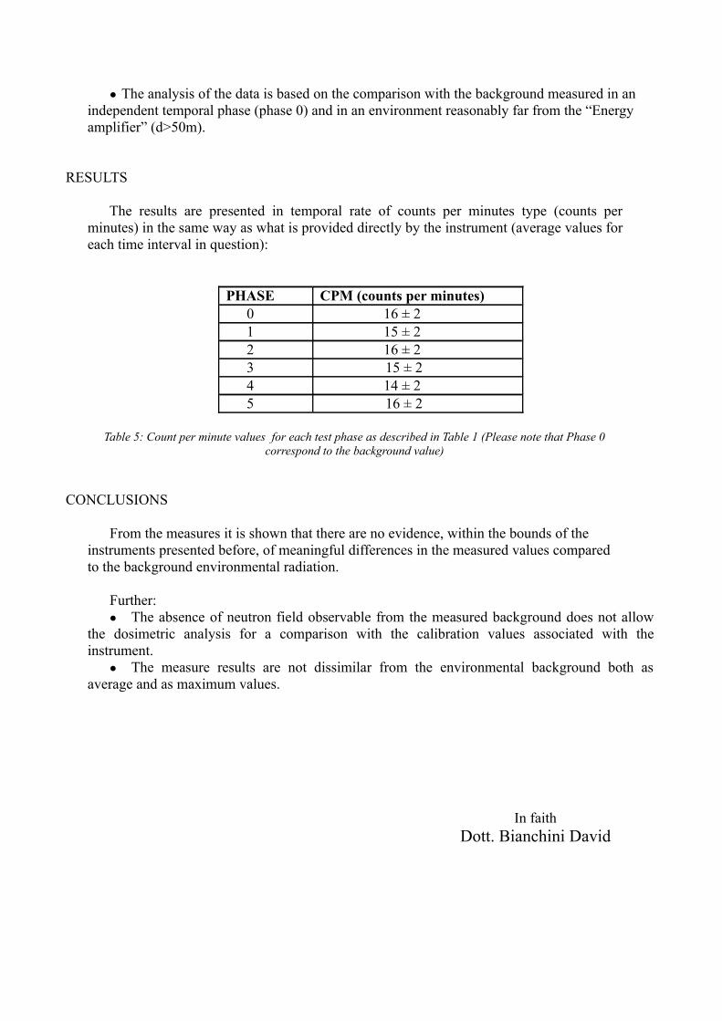
RESULTS
The results are presented in temporal rate of counts per minutes type (counts per minutes) in the same way as what is provided directly by the instrument (average values for each time interval in question):
PHASE CPM (counts per minutes)0 16 ± 21 15 ± 22 16 ± 23 15 ± 24 14 ± 25 16 ± 2
Table 5: Count per minute values for each test phase as described in Table 1 (Please note that Phase 0 correspond to the background value)
CONCLUSIONS
From the measures it is shown that there are no evidence, within the bounds of the instruments presented before, of meaningful differences in the measured values compared to the background environmental radiation.
Further:● The absence of neutron field observable from the measured background does not allow
the dosimetric analysis for a comparison with the calibration values associated with the instrument.● The measure results are not dissimilar from the environmental background both as
average and as maximum values.
In faithDott. Bianchini David
On the γ radiation measurements
on the Rossi system
Mauro Villa,
Bologna University and INFN Sezione di Bologna
January 26, 2011
Abstract
We report here on the measurement of γ emission from the sys-tem built by Rossi et al. to produce energy. While the details ofthe production system are still not known, an international patentrequest (WO/2009/125444) and a paper describing the main char-acteristics and performances are available: copper synthesis startingfrom an hydrogenated nickel compound and energy production last-ing for monthes. On the 14th of January 2011, the first public testof this system was performed under partially controlled conditions.Since the interpretation proposed by the authors for the energy pro-duction and for the copper synthesis are the chain reactions involv-ing X−1Ni + p →
XCu + Q (fusion), XCu →X Ni + e+ + ν + Q (β+
decay) and XCu + e− →XNi + ν + Q (electron capture) the system
internal should produce a significant amount of γ radiation produceddirectly or through the annihilation reaction e+e− → γγ. The energypower input and output and gamma radiations were measured before,during and after the active phase of the system, as well as the hy-drogen consumption. While a net energy output was observed, no γexcess (with energy above 200keV ) has been measured above the nat-ural background level (< 180Hz rate in single mode, compared to anexpected rate largely in excess of 1 MHz). The theoretical interpreta-tion of the effect mentioned in the patent filed and in the paper seemsto be therefore not adequate. Moreover, the short duration of thepreliminary test (45 minutes) and the test conditions, suggest there-fore to conduct accurate and long measurements before drawing anyconclusion on the nature of the energy production process.
1

1 Introduction
1.1 Patent claims and theoretical interpretation
The international patent request WO/2009/125444 [1] describes a remark-ably simple system able to produce heat. The basic building blocks are:1) a tube (reaction chamber) containing nickel powder and other elements(reaction catalyzers) filled with hydrogen gas, 2) several resistors used toheat the chamber and 3) a cooling system where liquid water is flown inand water steam is obtained in output. The main patent claim is on ”amethod and apparatus for carrying out highly efficient exothermal reactionbetween nickel and hydrogen atoms”. In the description of the patent, it ismentioned that only during the initial phase (lasting up to 3-4 hours) anelectric resistor is needed to bring the reactor up to the working point; after-wards the resistor can be switched off and the system can be self-sustained,producing more energy than that initially required.
Although unsure and only hypothetical, a possible interpretation for theenergy production, mentioned in the patent request, are the nuclear reactionchains X−1Ni + p →
X Cu + Q (copper production) and XCu →X Ni + e++
+ν + Q (copper β+ decay) or XCu + e− →X Ni + ν + Q (electron capture).
Starting from stable nickel nuclei, the mentioned reactions should lead finallyto stable copper nuclei: 63Cu and 65Cu. Two arguments are presented infavor of this interpretation:
• given the small amount of nickel powder involved, the large energyproduction seems not to be compatible with a chemical origin;
• the post-reaction analysis of the powder shows nuclei not present be-fore reaction.
In addition to the patent request content, a paper [2] published on webprovides more quantitative information: the power production can last formonthes and the isotopic composition of copper nuclei in the powder changesfrom a ratio of 63Cu/65Cu=2.24 (natural composition) to 1.6 after heatproduction (statistical and systematic uncertainties are not quoted). Forthese (and other) reasons, the authors claimed to have found a ”uniquesystem ... able to obtain energy from nuclear fusion reactions”, despite thefact that no nuclear activity has been measured during reactor functioning(outside shielding).
2
2 Preliminary considerations
This patent request and the related article rose a lot of interest in the nu-clear physics community. Since the new method and the new concept ofnuclear reactions (labelled elsewhere as ”Low Energy Nuclear Reactions”,LENR) challenge the basis of the nuclear physics field, a deep independentinvestigation is needed to confirm these findings. As a general rule, the more
extraordinary the scientific claims are, as in this case, the deeper should be
the investigation to rule out common and quite well known effects.In the first public demonstration of the reactor, we were allowed to per-
form measurements before, during and after reaction functioning. Even ifthe measurements were severely limited by the non disclosure of the reac-tion chamber and of the associated electronics, nevertheless some importantaspects have been tested:
• Energy production. To test the claim of non-chemical origin of theenergy produced, the measure of the output-input power difference in-tegrated times the measuring time (i.e. the total energy produced) isneeded and should be compared with the mass and size of the energysource. For example 1 MWh produced by 1 g of material is a good in-dication of a nuclear origin, while 5 Wh produced by 30 g of material isan indication of chemical origin. In the present test, as a precautionaryattitude, whatever was not known, not disclosed or not understood hasbeen considered as the energy source. This forces to consider relevantonly very large energy productions, as those described in [1] where thereactor has been working for weeks and monthes.
• Radiation detection. To test the theoretical interpretation of the en-ergy production a doubtless conclusion would be to identify signaturesof nuclear reactions. Since, to our knowledge, there is no nucleartransmutation reaction chain that proceeds without producing gam-mas (sooner or later), the radiation detectors can be used to searchany other (less direct) sign of nuclear activity, such as gammas of anyorigin, providing support for the nuclear interpretation of the energyreleased. In [2], a value of 35 MeV is evaluated as a mean energy pro-duction for Ni nuclei starting the reaction chain, part of it necessaryreleased as direct γ. The clearest signature is however the identifica-tion of two 511 keV γ from e+e− annihilation, which would follow anyβ+ decay of copper nuclei. This is actually a clean signature since:1) it requires two simultaneously signals in two different detectors, 2)characteristic topology (back-to-back) of the γ (to be matched with
3
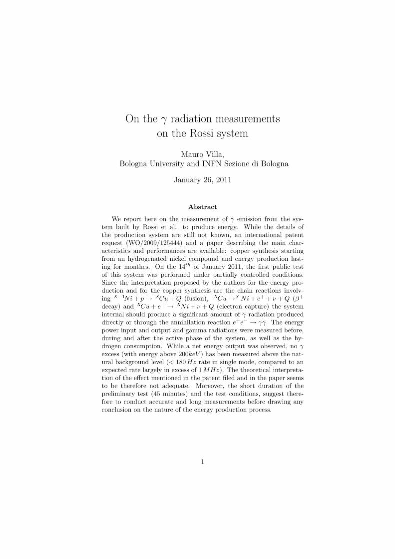
Figure 1: A photo of the apparatus. One scintillator detector is pointingupwards and is visible in the center of the picture, while the other is partiallycovered in the back.
the detector placement) and 3) the annihilation rate should follow thepower production: zero before reactor starting, increase (or flat top)during functioning and decrease after reactor switching off. Thesethree independent indications (if coherent) would provide a strongsupport of the claimed effects and their theoretical interpretation.
3 Experimental set-up
The experimental set-up is shown in fig 1. The basic observable elements arean horizontal metallic tube (approximate length 70 cm, diameter 20 cm, 22 l
4
volume, 30 kg weight as a guess-estimate) as the reaction chamber, a verticaltube for steam output (50 cm length, 15 cm diameter, 9 l volume), a con-trol system box (approx 40x40x40 cm3 dimensions, 64 l volume, unknownweight), a water pump and an hydrogen bottle. In the patent request [1]and in the paper [2] the horizontal tube is described as containing a reactionchamber where a nickel powder, catalyzers and the H2 react to provide en-ergy. In order to start the energy production the system should be operatedat high temperature, therefore electric resistors are used for initial heating.An heat sink composed by a flowing water transforming into steam is usedto draw the heat from the tube internal. An external shielding (thicknessunknown) covers all the details to the external observer. The vertical tubeis used for dry steam production. The control system box is practically theonly element receiving electrical power from outside, and drives the resistorswith 5 double-wire electrical cables. A pump provided a stable liquid waterflow in the inside of the horizontal tube system and an hydrogen bottle wasconnected to the reaction chamber.
Several parameters were controlled during the tests:
• the input electrical power was measured on a power meter and recordedevery 8 seconds;
• the environment temperature, the input water temperature, the out-put water steam temperature were logged every 2 seconds;
• the vapor quality was measured online;
• the water flux was measured at the beginning and assumed constant;
• gamma production from the system was monitored with NaI counters(main subject of this report);
• the environmental radiation was measured online (described in [3]).
No flux measurement has been done on the output steam flow. Tem-perature parameters and input-output power measurements are describedin detail in [4].
4 Gamma detection set-up and preliminary con-
trol measurements
The measurements of the γ radiation was performed with two identicalNaI(Tl) scintillators. The active volume is a cylinder of 3 inch diameter
5
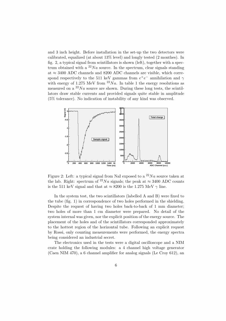
and 3 inch height. Before installation in the set-up the two detectors werecalibrated, equalized (at about 13% level) and longly tested (2 monthes). Infig. 2, a typical signal from scintillators is shown (left), together with a spec-trum obtained with a 22Na source. In the spectrum, clear signals standingat ≈ 3400 ADC channels and 8200 ADC channels are visible, which corre-spond respectively to the 511 keV gammas from e+e− annihilation and γwith energy of 1.275 MeV from 22Na. In table 1 the energy resolutions asmeasured on a 22Na source are shown. During these long tests, the scintil-lators draw stable currents and provided signals quite stable in amplitude(5% tolerance). No indication of instability of any kind was observed.
Time (ns)0 200 400 600 800 1000 1200 1400 1600
Sig
nal (
V)
-3
-2.5
-2
-1.5
-1
-0.5
0
Sample signal
ADC Channel (a.u.)0 2000 4000 6000 8000 10000
Cou
nts
0
500
1000
1500
2000
2500
3000
3500
4000
4500
Total charge
Figure 2: Left: a typical signal from NaI exposed to a 22Na source taken atthe lab. Right: spectrum of 22Na signals; the peak at ≈ 3400 ADC countsis the 511 keV signal and that at ≈ 8200 is the 1.275 MeV γ line.
In the system test, the two scintillators (labelled A and B) were fixed tothe tube (fig. 1) in correspondence of two holes performed in the shielding.Despite the request of having two holes back-to-back of 1 mm diameter;two holes of more than 1 cm diameter were prepared. No detail of thesystem internal was given, nor the explicit position of the energy source. Theplacement of the holes and of the scintillators corresponded approximatelyto the hottest region of the horizontal tube. Following an explicit requestby Rossi, only counting measurements were performed, the energy spectrabeing considered an industrial secret.
The electronics used in the tests were a digital oscilloscope and a NIMcrate holding the following modules: a 4 channel high voltage generator(Caen NIM 470), a 6 channel amplifier for analog signals (Le Croy 612), an
6
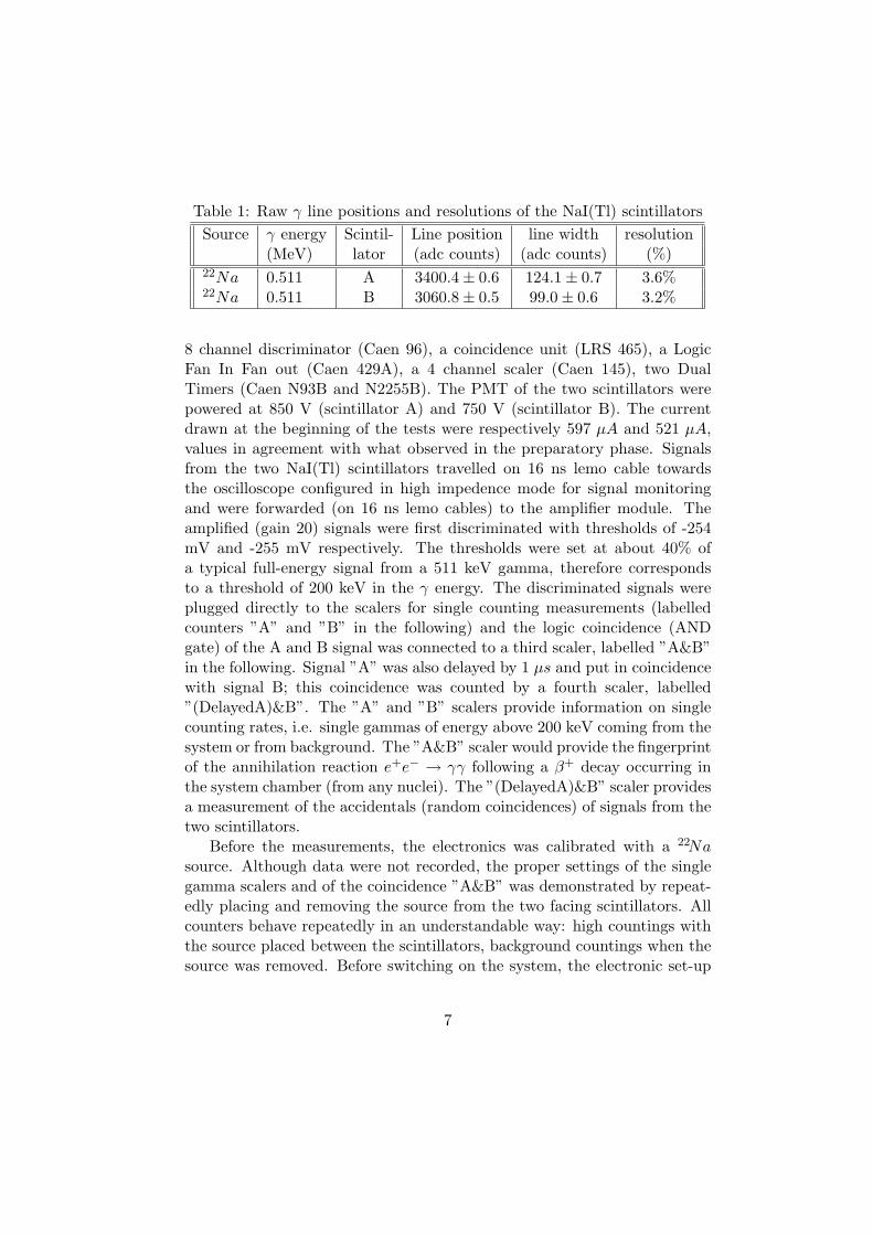
Table 1: Raw γ line positions and resolutions of the NaI(Tl) scintillators
Source γ energy Scintil- Line position line width resolution(MeV) lator (adc counts) (adc counts) (%)
22Na 0.511 A 3400.4 ± 0.6 124.1 ± 0.7 3.6%22Na 0.511 B 3060.8 ± 0.5 99.0 ± 0.6 3.2%
8 channel discriminator (Caen 96), a coincidence unit (LRS 465), a LogicFan In Fan out (Caen 429A), a 4 channel scaler (Caen 145), two DualTimers (Caen N93B and N2255B). The PMT of the two scintillators werepowered at 850 V (scintillator A) and 750 V (scintillator B). The currentdrawn at the beginning of the tests were respectively 597 µA and 521 µA,values in agreement with what observed in the preparatory phase. Signalsfrom the two NaI(Tl) scintillators travelled on 16 ns lemo cable towardsthe oscilloscope configured in high impedence mode for signal monitoringand were forwarded (on 16 ns lemo cables) to the amplifier module. Theamplified (gain 20) signals were first discriminated with thresholds of -254mV and -255 mV respectively. The thresholds were set at about 40% ofa typical full-energy signal from a 511 keV gamma, therefore correspondsto a threshold of 200 keV in the γ energy. The discriminated signals wereplugged directly to the scalers for single counting measurements (labelledcounters ”A” and ”B” in the following) and the logic coincidence (ANDgate) of the A and B signal was connected to a third scaler, labelled ”A&B”in the following. Signal ”A” was also delayed by 1 µs and put in coincidencewith signal B; this coincidence was counted by a fourth scaler, labelled”(DelayedA)&B”. The ”A” and ”B” scalers provide information on singlecounting rates, i.e. single gammas of energy above 200 keV coming from thesystem or from background. The ”A&B” scaler would provide the fingerprintof the annihilation reaction e+e− → γγ following a β+ decay occurring inthe system chamber (from any nuclei). The ”(DelayedA)&B” scaler providesa measurement of the accidentals (random coincidences) of signals from thetwo scintillators.
Before the measurements, the electronics was calibrated with a 22Nasource. Although data were not recorded, the proper settings of the singlegamma scalers and of the coincidence ”A&B” was demonstrated by repeat-edly placing and removing the source from the two facing scintillators. Allcounters behave repeatedly in an understandable way: high countings withthe source placed between the scintillators, background countings when thesource was removed. Before switching on the system, the electronic set-up
7
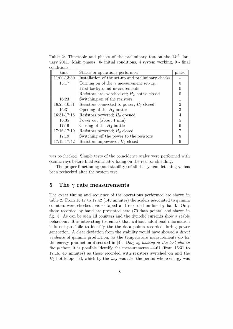
Table 2: Timetable and phases of the preliminary test on the 14th Jan-uary 2011. Main phases: 0- initial conditions, 4 system working, 9 - finalconditions.
time Status or operations performed phase
11:00-13:30 Installation of the set-up and preliminary checks -15:17 Turning on of the γ measurement set-up. 0
First background measurements 0Resistors are switched off; H2 bottle closed 0
16:23 Switching on of the resistors 116:23-16:31 Resistors connected to power; H2 closed 2
16:31 Opening of the H2 bottle 316:31-17:16 Resistors powered; H2 opened 4
16:35 Power cut (about 1 min) 517:16 Closing of the H2 bottle 6
17:16-17:19 Resistors powered; H2 closed 717:19 Switching off the power to the resistors 8
17:19-17:42 Resistors unpowered; H2 closed 9
was re-checked. Simple tests of the coincidence scaler were performed withcosmic rays before final scintillator fixing on the reactor shielding.
The proper functioning (and stability) of all the system detecting γs hasbeen rechecked after the system test.
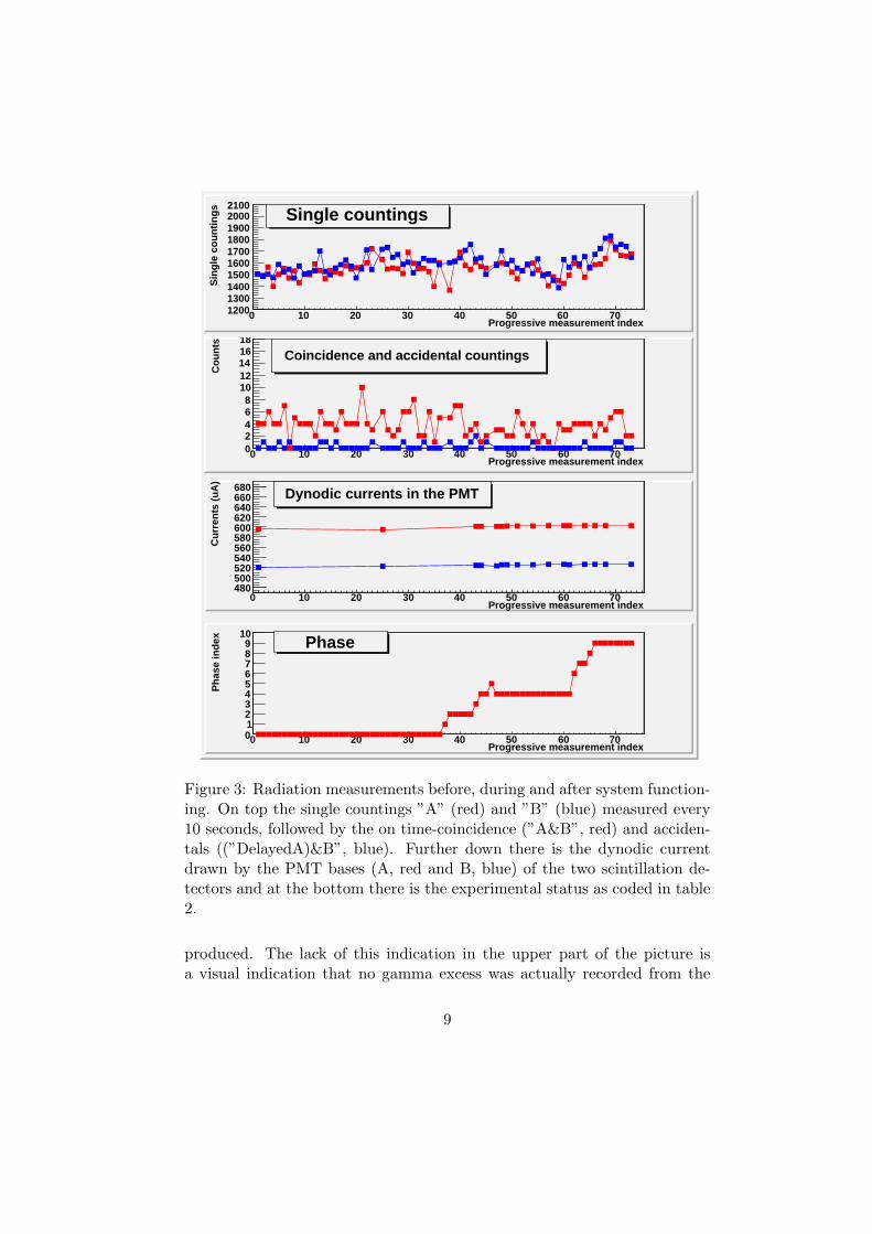
5 The γ rate measurements
The exact timing and sequence of the operations performed are shown intable 2. From 15:17 to 17:42 (145 minutes) the scalers associated to gammacounters were checked, video taped and recorded on-line by hand. Onlythose recorded by hand are presented here (70 data points) and shown infig. 3. As can be seen all counters and the dynodic currents show a stablebehaviour. It is interesting to remark that without additional informationit is not possibile to identify the the data points recorded during powergeneration. A clear deviation from the stability would have showed a direct
evidence of gamma production, as the temperature measurements do forthe energy production discussed in [4]. Only by looking at the last plot in
the picture, it is possible identify the measurements 44-61 (from 16:31 to17:16, 45 minutes) as those recorded with resistors switched on and theH2 bottle opened, which by the way was also the period where energy was
8
Progressive measurement index0 10 20 30 40 50 60 70
Sin
gle
coun
tings
1200130014001500160017001800190020002100
Single countings
Progressive measurement index0 10 20 30 40 50 60 70
Cou
nts
02468
1012141618
Coincidence and accidental countings
Progressive measurement index0 10 20 30 40 50 60 70
Cur
rent
s (u
A)
480500520540560580600620640660680 Dynodic currents in the PMT
Progressive measurement index0 10 20 30 40 50 60 70
Pha
se in
dex
0123456789
10Phase
Figure 3: Radiation measurements before, during and after system function-ing. On top the single countings ”A” (red) and ”B” (blue) measured every10 seconds, followed by the on time-coincidence (”A&B”, red) and acciden-tals ((”DelayedA)&B”, blue). Further down there is the dynodic currentdrawn by the PMT bases (A, red and B, blue) of the two scintillation de-tectors and at the bottom there is the experimental status as coded in table2.
produced. The lack of this indication in the upper part of the picture isa visual indication that no gamma excess was actually recorded from the
9
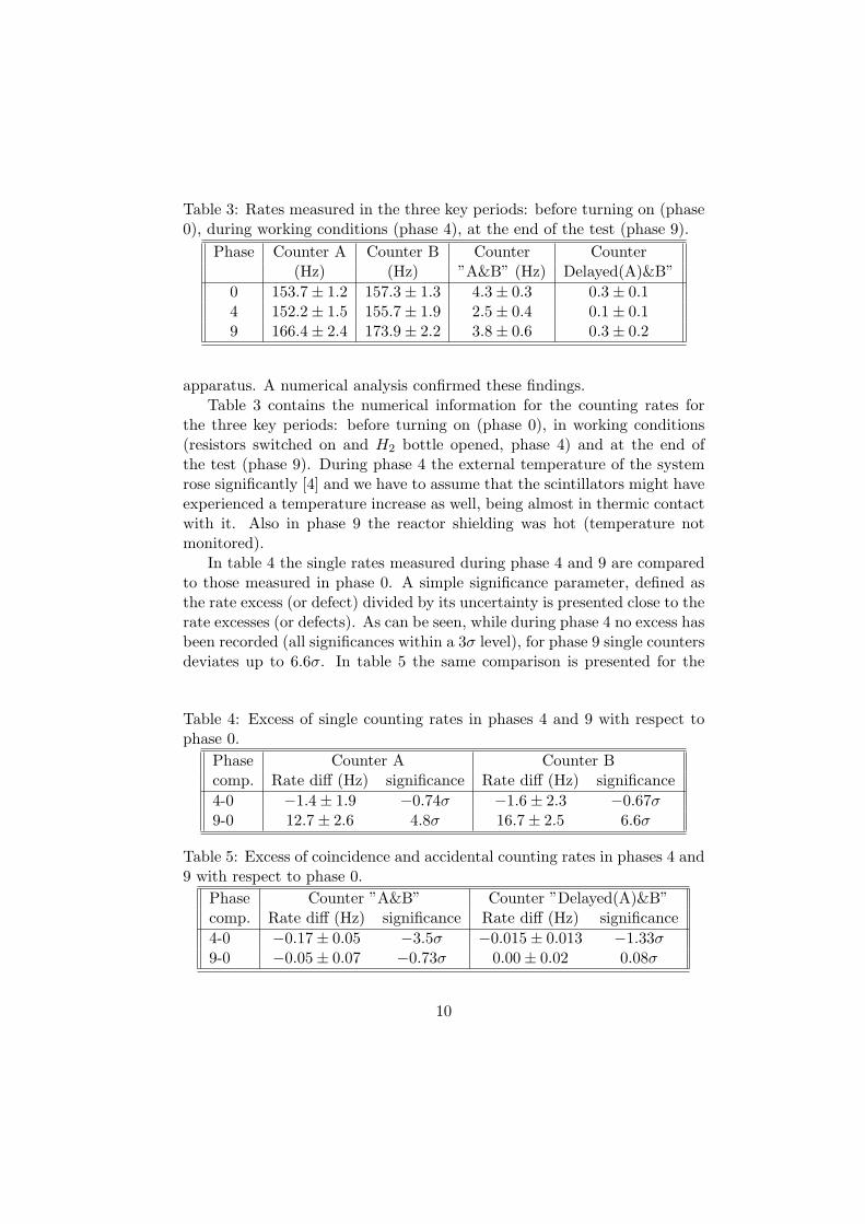
Table 3: Rates measured in the three key periods: before turning on (phase0), during working conditions (phase 4), at the end of the test (phase 9).
Phase Counter A Counter B Counter Counter(Hz) (Hz) ”A&B” (Hz) Delayed(A)&B”
0 153.7 ± 1.2 157.3 ± 1.3 4.3 ± 0.3 0.3 ± 0.14 152.2 ± 1.5 155.7 ± 1.9 2.5 ± 0.4 0.1 ± 0.19 166.4 ± 2.4 173.9 ± 2.2 3.8 ± 0.6 0.3 ± 0.2
apparatus. A numerical analysis confirmed these findings.Table 3 contains the numerical information for the counting rates for
the three key periods: before turning on (phase 0), in working conditions(resistors switched on and H2 bottle opened, phase 4) and at the end ofthe test (phase 9). During phase 4 the external temperature of the systemrose significantly [4] and we have to assume that the scintillators might haveexperienced a temperature increase as well, being almost in thermic contactwith it. Also in phase 9 the reactor shielding was hot (temperature notmonitored).
In table 4 the single rates measured during phase 4 and 9 are comparedto those measured in phase 0. A simple significance parameter, defined asthe rate excess (or defect) divided by its uncertainty is presented close to therate excesses (or defects). As can be seen, while during phase 4 no excess hasbeen recorded (all significances within a 3σ level), for phase 9 single countersdeviates up to 6.6σ. In table 5 the same comparison is presented for the
Table 4: Excess of single counting rates in phases 4 and 9 with respect tophase 0.
Phase Counter A Counter Bcomp. Rate diff (Hz) significance Rate diff (Hz) significance
4-0 −1.4 ± 1.9 −0.74σ −1.6 ± 2.3 −0.67σ9-0 12.7 ± 2.6 4.8σ 16.7 ± 2.5 6.6σ
Table 5: Excess of coincidence and accidental counting rates in phases 4 and9 with respect to phase 0.
Phase Counter ”A&B” Counter ”Delayed(A)&B”comp. Rate diff (Hz) significance Rate diff (Hz) significance
4-0 −0.17 ± 0.05 −3.5σ −0.015 ± 0.013 −1.33σ9-0 −0.05 ± 0.07 −0.73σ 0.00 ± 0.02 0.08σ
10
coincidence (A&B) and accidental (Delayed(A)&B) countings. Coincidencesshow only negative significances, with an lower value of −3.5σ. Accidentalsare compatible with no effects: all values below (3σ).
There are 3 measurements above the 3σ limit (two excesses and one lackof γs); a measurement above the 5σ (excess) and no 8σ effects. Since: 1) themeasurement above the 5σ has been taken with the reactor switched off; 2)the other 7 values are not always confirming this behavior (excesses and lacksof γs); 3) the effect of the temperature on our scintillators are unknown and4) radon contamination was not measured, by the precautionary principle it
is safe not to consider significant this single excess. A possibile explanationof the excess seen at the end of the tests concerns radon. Tap water wasused and transformed to steam (order of 7 liters/s of water steam diffused ina room near the apparatus. It is well known that in this process radon gasis released in the environment. Gamma radiative decays of radon or otherinstable nuclei in the radon decay chain could not be excluded and might bethe source of the delayed increase of environment radioactivity. More, longand accurate measurements should be performed in order to keep track ofthese possible contaminants.
An 8-σ criterion would have required to measure in any of the several 10s periods rates above these limits: > 185Hz (counter A), > 189Hz (counterB) and > 21Hz (coincidence). These values can be considered as a thresholdfor effect confirmation. No data value, fullfilling this criterion, is present inthe test. By the quoted numbers, it is possible to evaluate the sensitivityof the γ detection system: ≈ 30 Hz in single counting mode or ≈ 17 Hz incoincidence mode for signals above the background in a counting period of10 s.
6 Discussion
The energy measurements provided the following results, which are sum-marized in [4]: electrical power in input of about 1 kW; energy power inoutput about 12.7 kW for a time period of about 40 minutes. Assumingthat the observed energy excess production rate (≈ 11 kW) is coming fromnuclear reaction, knowing that a typical energy release is of the order of 1MeV, it is possible to estimate the total fusion rate to be of the order of7 · 1016 reaction/s (fusions or decays). Assuming that the reactions are dis-tributed along the hottest part of tube (30 cm lenght, where the detectorshave been placed), taking into account the solid angle seen by the two NaIdetectors through the two 1 cm diameter holes in the shielding (≈ 2.5 · 10−3
11
steradiants), a total rate largely in excess of 1011 γ/s can be estimated tobe emitted within the solid angle seen by the two detectors.
This rate is so huge that there is no possibility for it to escape detectionprovided that the γ have an energy above the 200 keV threshold. Notwith-standing the uncertainties of the energies of the gamma produced (511 keVand >1 MeV are just guesses) and the details of the shieldings, the energyrange (0.2-4 MeV) is well known to be difficult for gamma containment.In this region, in fact, for several materials, the dominant γ interaction iscompton scattering, an elastic process that changes the γ energy, but notthe γ counting in a relevant manner. Even assuming that the whole hor-izontal tube is made of lead (10 cm radius), we expected some γ to pass.In laboratory, in fact, the absorption of gammas from 22Na (a β+ emitter,releasing 511 keV and 1.275 MeV gammas) from different thickness of leadhas been measured with the same set-up and thresholds as those used inthe system test: 5 cm of lead are enough to reduce the unshielded flux to≈ 5.7%, while 10 cm of lead reduced the unshielded flux to ≈ 0.5% (singlecountings). Taking into account these numbers, one can easily conclude thatthe observed γ rates are incompatible with the expected ones (at least by 6orders of magnitude). This seems to rule out the explanation proposed for
the energy release (production of copper nuclei via reaction chains involvingβ+ decays).
7 Conclusions
The main findings of the present study are the following:
• the present reactor was actually able to vaporize a cold liquid wa-ter flux for about 40 minutes, showing a sizeable output-input powerdifference and an integrated power production of several kWh [4];
• no gamma radiation above the background level in the energy regionEγ > 200 keV has been observed, neither in single counting, not incoincidence;
• regardless of the internal details of the reaction chamber, shieldingsand other industrial secrets, the γ rates measured with the NaI coun-ters seem not compatible with the rates deduced or expected assumingthat the energy production was due to nuclear fusion or decay reac-tions, as suggested in [1].
Thus at present having found no nuclear reaction fingerprints, furtherinvestigations are indeed needed to identify the energy production process.
12
We are opened to collaborations with the proponents to complete the testsby covering also the low energy gamma region (20 − 200 keV ), to measurepossibly slow or fast neutron emissions and to perform measurements onlong runs. The duration of the tests would be directly proportional to themass and volume of unknown origin. For the present set-up a convincingevidence would include a power production of (order of) 10 kW sustainedfor weeks in a controlled and monitorized environment.
Acknowledgements
The author wishes to thank Ing. Rossi and Prof. Focardi for letting thesemeasurements to take place and all the people involved for their cooperation.
Disclaimer
The present report concerns mainly the radiation measurements to confirmor disproof the nuclear interpretation of the energy release. Very clean andundoubltfull signals were looked for. Measurement conditions were not idealin few cases (weighing procedures, duration, systematics, fluxes) and needsto be redone properly.
References
[1] A. Rossi (inventor), Method and Apparatus for Carrying out
Nickel and Hydrogen Exothermal Reactions, (WO/2009/125444)http://www.wipo.int/pctdb/en/wo.jsp?WO=2009125444;
[2] S. Focardi and A. Rossi, A new energy source from nuclear fu-
sion, Journal of Nuclear Physics, http://www.journal-of-nuclear-physics.com/?p=66, February 2010;
[3] D. Bianchini, Experimental evaluation, for radiation protection purpose,
of photon and neutron radiation field during the public presentation of
the prototype called ”Energy Amplifier”. http://www.journal-of-nuclear-physics.com
[4] G. Levi, Report on heat production during preliminary tests on the Rossi
”Ni-H” reactor, http://www.journal-of-nuclear-physics.com.
13