report hydraulic jumps
TRANSCRIPT

PART A: THE HYDRAULIC JUMPS
1.0 INTRODUCTION
A hydraulic jump is a fluid shockwave created at the transition between laminar and
turbulent flow. One common example of a hydraulic jump can be seen in the water
radiating outward when the stream of tap water strikes the horizontal surface of a sink.
The water initially flows in a smooth sheet with consistent current patterns. In this region,
the speed of the water exceeds the local wave speed. Friction against the sink surface
slows the flow until an abrupt change occurs. At this point, the depth increases as water
piles up in the transition region and flow becomes turbulent. The motion of individual
water molecules becomes erratic and unpredictable. The interruption of flow patterns
also reduces the kinetic energy of the water. In addition to the kitchen sink example,
hydraulic jumps are also typical features of river rapids where the water swirls and foams
around rocks and logs.
2.0 OBJECTIVE
To investigate the characteristic a standing wave (the hydraulic jump) produced
when waters beneath an undershot weir and to observe the flow patterns obtained.
3.0 LEARNING OUTCOMES
At the end of the course, students should be able to apply the knowledge and skills
they have learned to:
a. Understand the concept and characteristics of hydraulic jump.
b. Understand the factors which influence the hydraulic jump.

4.0 THEORY
When water flowing rapidly changes to slower tranquil flow, a hydraulic jump or standing
wave is produced. This phenomenon can be seen where water shooting under a sluice
gate mixes with deeper water downstream. It occurs when a depth less than critical
changes to a depth which is greater than critical and must be accompanied by loss of
energy. An andular jump occurs when the change in depth is small. The surface of the
water undulates in a series of oscillations, which gradually decay to a region of smooth
tranquil flow. A direct jump occurs when the change in depth is great. The large amount
of energy loss produces a zone of extremely turbulent water before it settles to smooth
tranquil flow.
By considering the forces acting within the fluid on either side of a hydraulic jump of unit
width it can be shown that:
ΔH=d a+va2
2 g−(db+ vb22g )
Where, ΔH is the total head loss across jump (energy dissipated) (m), va is the mean
velocity before jump (m/s), da is the depth of flow before hydraulic jump (m), vb is the
mean velocity after hydraulic jump (m) and db is the depth of flow after hydraulic jump
(m). Because the working section is short, da≈d1 and db≈d3 . Therefore, simplifying
the above equation, ΔH=(d3−d1)3 /4 d1d3 .

5.0 EQUIPMENTS USED
Clear-acrylic rectangular open channels Sump tank
supported by steel frames (0.3m width)
Switch pump with water meter

Rectangular sluice gate (0.3m width) Control valve & pump
2 units measurement gauges 1 meter long steel ruler
Plasticine

6.0 EXPERIMENTAL METHODS
1. Ensure the flume is level, with the downstream tilting overshot weir, E at the
bottom of its travel. Measure and record the actual breadth b (m) of the
undershot weir. Install the undershot weir towards the inlet end of the flume and
ensure that it is securely clamped in position.
2. Adjust the undershot weir to position the sharp edge of the weir 20 mm above the
bed of the channel. Increase the height of the tilting overshot weir until the
downstream level just start to rise.
3. Gradually open the flow control valve and adjust the flow until an andular jump is
created with small ripple decaying towards the discharge end of the working
section. Observe and sketch the flow pattern.
4. Increase the height of water upstream of the undershot weir by increasing the
flow rate and increase the height of the tilting overshot weir to create a hydraulic
jump in the center of the working section. Observe and sketch the flow pattern.
5. Measure and record the values ofd1 , d3 , d g and q . Repeat this for other flow
rates q (upstream head) and heights of the gated g .
7.0 SAMPLE DATA
Channel Width, b=0.30m
Weir Opening
,
Upstream Flow Depth,
Flow Depth Above Jump,
Flow Depth Below Jump,
Flow Rate,
∆H V1 ∆H/d1 d3/d1
dg (m) do (m) d1 (m) d3 (m) Q (m3/s)
0.20 0.3145 0.0173 0.0944 0.011 0.0702 0.1833 4.0554 5.4566
0.21 0.3184 0.0155 0.0918 0.011 0.0780 0.1746 5.0351 5.9226
0.22 0.3085 0.0166 0.0943 0.011 0.0749 0.1667 4.5131 5.6807
0.23 0.2625 0.0171 0.0941 0.011 0.0709 0.1594 4.1479 5.5029
0.24 0.2508 0.0210 0.0938 0.011 0.0490 0.1528 2.3318 4.4667

Table 7.1. The Hydraulic Jumps
7.1 Calculate V1 and plot dg against V1
7.2 Calculate ∆H/d1 and plot ∆H/d1 against d3/d1
7.3 Calculate dc and verify d1<dc<d3
8.0 ANALYSIS OF RESULTS, EQUATIONS USED
8.1 Equation used for V1, Q=AV
V=Q/A
A=dg x b =0.20 x 0.30 =0.060m2
V=Q/A =0.011/0.06 =0.1833m/s
A=dg x b =0.21 x 0.30 =0.063m2
V=Q/A =0.011/0.063 =0.1746m/s
A=dg x b =0.22 x 0.30 =0.066m2
V=Q/A =0.011/0.066 =0.1667m/s
A=dg x b =0.23 x 0.30 =0.069m2
V=Q/A =0.011/0.069 =0.1594m/s
A=dg x b =0.24 x 0.30 =0.072m2
V=Q/A =0.011/0.072 =0.1528m/s
0.15 0.200.20
0.21
0.22
0.23
0.24
0.25
Graph 8.1. dg against V1
dg/V1
, V1
dg ,

8.2 Equation used for ∆H = (d3-d1)3 / 4d1d3
∆H = (0.0944-0.0173)3
4(0.0173)(0.0944)
= 0.0702m
∆H = (0.0918-0.0155)3
4(0.0155)(0.0918)
= 0.0780m
∆H = (0.0943-0.0166)3
4(0.0166)(0.0943)
= 0.0749m
∆H = (0.0941-0.0171)3
4(0.0171)(0.0941)
= 0.0709m
∆H = (0.0938-0.0210)3
4(0.0210)(0.0938)
= 0.0490m
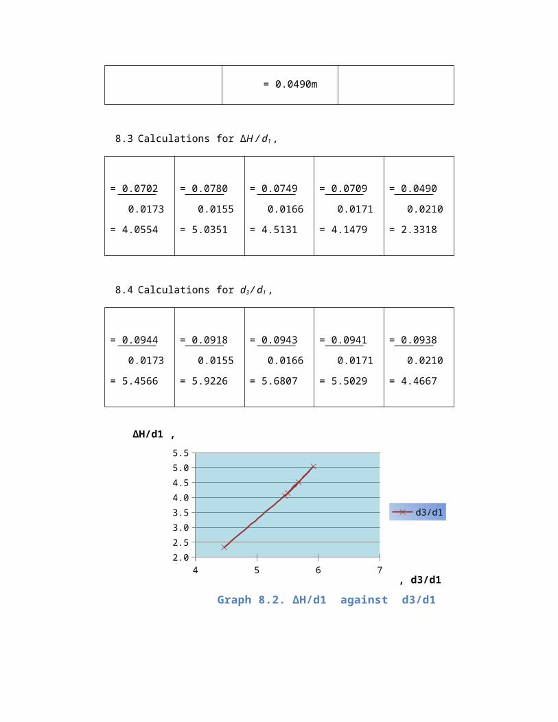
8.3 Calculations for ∆H / d1 ,
= 0.0702
0.0173
= 4.0554
= 0.0780
0.0155
= 5.0351
= 0.0749
0.0166
= 4.5131
= 0.0709
0.0171
= 4.1479
= 0.0490
0.0210
= 2.3318
8.4 Calculations for d3 / d1 ,

4 5 6 72.0
2.5
3.0
3.5
4.0
4.5
5.0
5.5
Graph 8.2. ∆H/d1 against d3/d1
d3/d1
, d3/d1
∆H/d1 ,
8.5 Calculations for Critical depth, dc = (q2/g)1/3 , where q = Q/b
= (0.03672/9.81)1/3 = 0.011/0.3
= 0.0516m = 0.0367m3/s/m
and acceleration due to grativy, g = 9.81m2/s
dc
Verifications, if d1<dc<d3
0.20m0.0173<0.0516<0.0944
0.21m0.0155<0.0516<0.0918
0.22m0.0166<0.0516<0.0943
0.23m0.0171<0.0516<0.0941
= 0.0944
0.0173
= 5.4566
= 0.0918
0.0155
= 5.9226
= 0.0943
0.0166
= 5.6807
= 0.0941
0.0171
= 5.5029
= 0.0938
0.0210
= 4.4667

0.24m0.0210<0.0516<0.0938
9.0 QUESTIONS
1) Verify the force of the stream on either side of the jump is the same and that the
specific energy curve predicts a loss equal to ∆H/dc.
Fbefore = Fafter
2) Suggest application where the loss of energy in hydraulic jump would be
desirable. How is the energy dissipated?
The hydraulic jump flow process can be illustrated by use of the specific energy
concept. Equation loss energy can be written in term of the specific energy:
E = do + V2/ 2g
Where do and E are feet. Because of the head loss across the jump, the
upstream values of E are different. About the graph, (1) to state (2) the fluid does
not proceed along the specific energy curve and pass through the critical
condition. The energy dissipates when water flow at weir opening and the energy
became 0 because d0 and d3 has are force from adverse. Same like the equation,
Fbefore = Fafter.
Practical applications of hydraulic jumps:
Dissipation of energy of water flowing over dams and weirs – to prevent
possible erosion and scouring due to high velocities.
Raising water levels in canals to enhance irrigation practices and reduce
pumping heads.
Reducing uplift pressure under the foundations of hydraulic structures.
Creating special flow conditions to meet certain special needs at control
sections – gaging stations, flow measurement, flow regulation.
10.0 COMPARISON WITH THEORY, DISCUSSION
11.0 CONCLUSIONS